Embed Size (px)
Citation preview

APS/AES
DESIGN AND DRAFTING STANDARDS
Revised 10/8/13

ii
iii
FOREWORD
This APS/AES Design and Drafting Standards manual has been compiled in order for the
Advanced Photon Source’s Design and Drafting Group to better communicate design
requirements to our customers and vendors.
When components are built for the Advanced Photon Source, close adherence to the standards
established in this manual are essential. Following these standards means that the components
will meet our requirements, and more importantly, that the components supplied by the
vendors will meet the Advanced Photon Source’s quality standards for the useful life of the
facility.
Although this manual presents a consolidation of available information, it is impractical to
include all data pertinent to the fabrication of components; therefore, sound reasoning and good
judgment must be exercised in making interpretations from this manual. In addition to this
manual the Design and Drafting Group adheres to the industry standard for dimensioning and
tolerancing, ASME Y14.5-2009.
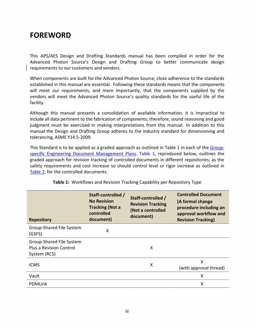
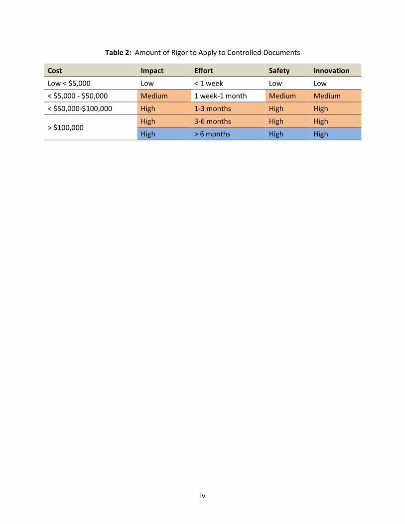
This Standard is to be applied as a graded approach as outlined in Table 1 in each of the Group-
specific Engineering Document Management Plans. Table 1, reproduced below, outlines the
graded approach for revision tracking of controlled documents in different repositories; as the
safety requirements and cost increase so should control level or rigor increase as outlined in
Table 2, for the controlled documents.
Table 1: Workflows and Revision Tracking Capability per Repository Type
Repository
Staff-controlled /
No Revision
Tracking (Not a
controlled
document)
Staff-controlled /
Revision Tracking
(Not a controlled
document)
Controlled Document
(A formal change
procedure including an
approval workflow and
Revision Tracking)
Group-Shared File System
(GSFS) X
Group-Shared File System
Plus a Revision Control
System (RCS)
X
ICMS X X
(with approval thread)
Vault X
PDMLink X
iv
Table 2: Amount of Rigor to Apply to Controlled Documents
Cost Impact Effort Safety Innovation
Low < $5,000 Low < 1 week Low Low
< $5,000 - $50,000 Medium 1 week-1 month Medium Medium
< $50,000-$100,000 High 1-3 months High High
> $100,000 High 3-6 months High High
High > 6 months High High
v
Table of Contents
CHAPTER 1: GENERAL STANDARDS ............................................................................................. 1
CHAPTER 2: AUTOCAD PRACTICES............................................................................................... 5
CHAPTER 3: PRO/E PRACTICES .................................................................................................... 8
CHAPTER 4: DIMENSIONING & TOLERANCING .......................................................................... 13
CHAPTER 5: WINDCHILL/PDMLINK ............................................................................................ 16
CHAPTER 6: VAULT .................................................................................................................... 17
CHAPTER 7: PURCHASED PARTS ................................................................................................ 18
CHAPTER 8: VACUUM STANDARDS ........................................................................................... 25
CHAPTER 9: DRAWING NUMBERS ............................................................................................. 33
CHAPTER 10: APPROVAL ........................................................................................................... 41
CHAPTER 11: PRINTING AND STORAGE ..................................................................................... 45
CHAPTER 12: FACILITIES DESIGN STANDARDS ........................................................................... 49
CHAPTER 13: SAFETY INTERLOCK SYSTEMS ............................................................................... 57
CHAPTER 14: REFERENCES ........................................................................................................ 60

vi
1
CHAPTER 1: GENERAL STANDARDS
1.0 INTRODUCTION Adherance to general drafting rules and practices is important for producing drawings of
consistent and professional quality. The use of special or local practices is strongly
discouraged to ensure accurate interpretation of the wide variety of APS drawings
produced. In this chapter, designers are assumed to already have a thorough knowledge
of drafting and, therefore, most basic rules and practices are omitted. Conventional
facilities and electrical drawings follow separate standards, which can be found in
separate chapters.
The accuracy and adequacy of design and drafting work and its compliance with the
applicable standards remain the responsibility of the engineer, designer, or drafter.
Nothing contained in this manual shall be construed as relieving the engineer, designer,
or drafter of their individual responsibility for producing quality drawings.
This chapter only covers basic rules and practices; for a more detailed look at drafting
standards please refer to the Genium Group Standards “Modern Drafting Practices and
Standards Manual” located in the Design and Drafting Room.
1.1 GENERAL STANDARDS
1.1.1 DRAWING STANDARDS
The content of this manual is intended to be consistent with the following American
national standards:
� Modern Drafting Practices and Standards, Genium Group
� Standard Symbols for Welding, Brazing and Nondestructive Examination, AWS
A2.4-93 Surface Texture, ASME B46.1-2002
� Dimensioning and Tolerancing, ASME Y14.5M-2009
1.1.2 PURCHASED PARTS
Commercially available components are to be used whenever possible. All information
required for purchasing the component should be furnished on the drawing. Further
information on working with purchased parts is specified in Chapter 7.
1.1.3 DETAIL DRAWINGS ON SEPARATE SHEETS
It is recommended that each part shall be detailed on a separate sheet. Weldments and
architectural drawings are an exception. If there is a question as to whether a specific
weldment or assembly may be detailed on one drawing, consult with the CAD supervisor.
2
1.1.4 MULTIPLE-SHEET DRAWINGS
The use of multiple-sheet drawings should be avoided if possible. If multiple-sheet
drawings must be used, they must have the same log number and document number
listed in the title block. All sheets must have the same title (i.e., Title1 through Title5)
listed in the title blocks, and the sheets must be the same size and scale. When revising
multiple-sheet drawings, the revision level must be updated on all sheets. Multiple-sheet
drawings in AutoCAD format must be in the same file and comply with the layout
standard for proper system conversions as specified in Chapter 2.
1.1.5 DRAWING INFORMATION
Each detail is to contain all information needed for fabrication independent of other
drawings (with the possible exception of drill-on-assembly techniques). This includes, but
is not limited to:
� Specific materials called for by name, identifying number, and specification.
ASTM notes may be added as needed. Many specifications may be found online
at sites such as matweb.com.
� Material hardness and hardness depth
� Annealing and stress relieving
� Surface texture and coating symbols
� Weld symbols with joining sizes and other requirements
� Testing specifications, such as pressure test, vacuum tests, dye-penetrant test,
magna- flux test, radiographic test, etc.
� Coating specifications such as painting, plating, etc.
� Brazing specifications
� Drawings of heavy components in excess of fifty pounds shall have the calculated
weight indicated on the part/assembly. In special cases, add provisions for
lifting.
� Identification of all assemblies with the drawing number
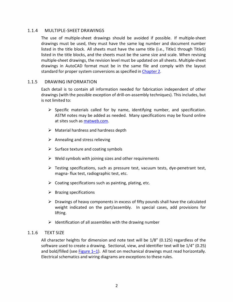
1.1.6 TEXT SIZE
All character heights for dimension and note text will be 1/8” (0.125) regardless of the
software used to create a drawing. Sectional, view, and identifier text will be 1/4” (0.25)
and bold/filled (see Figure 1–1). All text on mechanical drawings must read horizontally.
Electrical schematics and wiring diagrams are exceptions to these rules.
3
Figure 1–1: Pro/E defaults to proper font sizes for view identifier text, but designers must
change font type.
1.1.7 FONT STYLE
All character fonts for dimension and note text in Pro/Engineer will be “FONT”.
Sectional, view, and identifier text will be “FILLED”.
All character fonts for dimension and note text in AutoCAD will be “RomanS”. Sectional,
view, and identifier text will be “RomanD”.
1.1.8 PRINTS FOR VENDORS
All prints to vendors must come from the Document Control Center (DCC) and have the
proper stamp. Prints are not to leave the laboratory with penciled or penned markings.
A formal revision must be made to reflect any alteration from the printed design.
1.1.9 STANDARD SHEET SIZES
Table 1–1 shows the standard sheet sizes in units of inches.
Table 1–1: Standard Drawing Sheet Sizes
Letter Designation Width Length
A 8-1/2 11
B 11 17
C 17 22
D 22 34
E 34 44 (preferred)
F 28 40
1.1.10 ABBREVIATIONS
Abbreviations shall be used only when their meanings are unquestionably clear and shall
be per ANSI Y1.1, “Abbreviations for Use on Drawings and in Text,” of the American
Society of Mechanical Engineers.
4
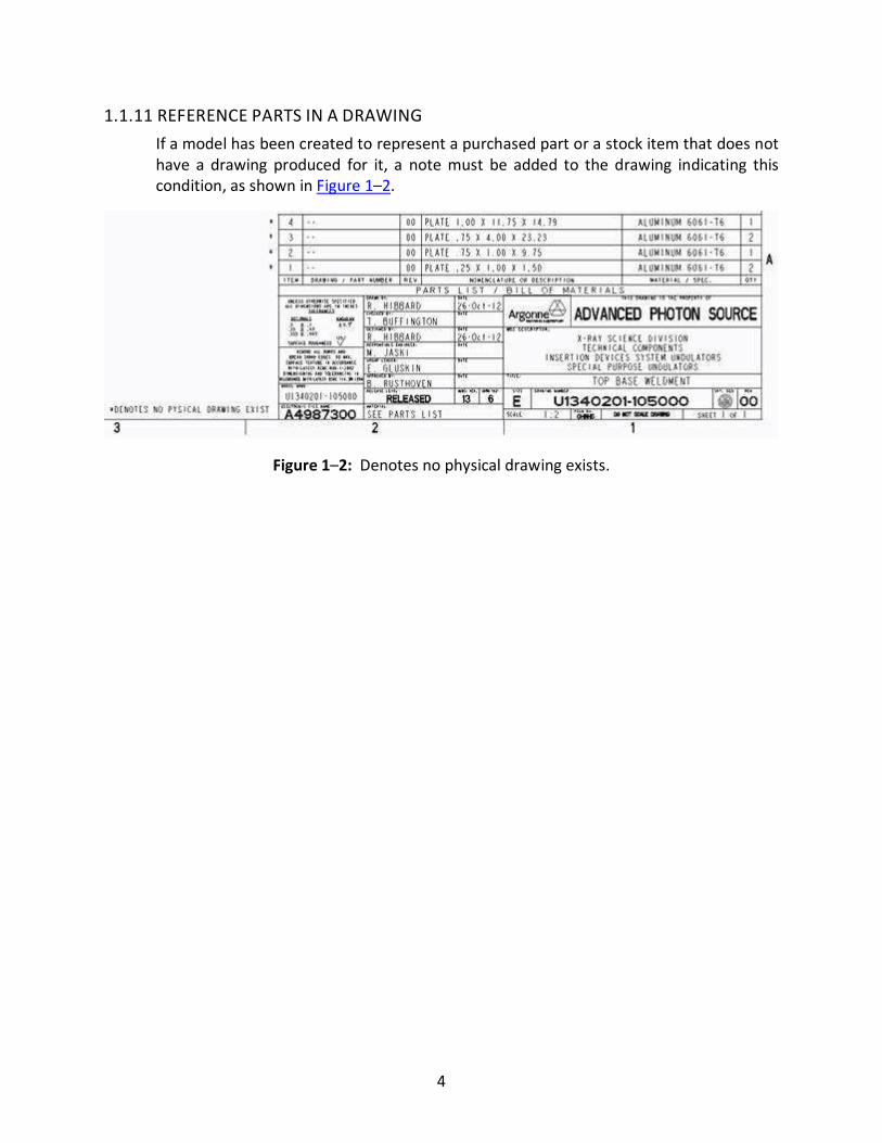
1.1.11 REFERENCE PARTS IN A DRAWING
If a model has been created to represent a purchased part or a stock item that does not
have a drawing produced for it, a note must be added to the drawing indicating this
condition, as shown in Figure 1–2.
Figure 1–2: Denotes no physical drawing exists.
5
CHAPTER 2: AUTOCAD PRACTICES
2.0 INTRODUCTION The standard software at APS for creating new mechanical drawings is Pro/E. AutoCAD,
however, has a number of roles at APS including creating and revising electrical
schematics, ray tracings, and conventional facilities drawings.
Small revisions to existing AutoCAD mechanical drawings are acceptable. However,
when a revision is extensive, it is strongly suggested that consideration be given to
recreating parts in Pro/E. The benefits of having a solid model for use in a Pro/E
assembly may warrant the time required for the format conversion. The choice of
whether to invest this time is primarily left to the designer and engineer.
The purpose of this section is to outline recommended general AutoCAD practices that
promote drafting efficiency as well as accessibility and portability of drawings.
2.1 GENERAL AUTOCAD RULES
2.1.1 STARTING A NEW DRAWING
New drawings should be started using the APS AutoCAD template. This template
contains APS standard dimension and text styles as well as layers and should load
automatically when a new drawing is started. See Table 1–1 for a complete listing of
standard AutoCAD layers and linetypes.
NOTE: If the template does not automatically load after pushing the ‘new drawing’ icon,
there may be a problem with the profile (preferences). Contact Computer Support to
correct this problem.
All AutoCAD support files such as symbols, templates, title bocks, etc. are located on the
server Lead (‘P:’ drive; Figure 2–1). A standard profile (ddr.arg) that contains paths to
these support directories is also available. The profile may be customized locally as a
copy for specific work requirements. For help with profiles and support files, please
contact the CAD supervisor.
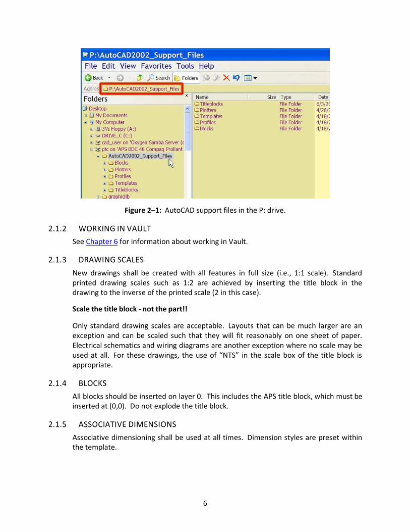
6
Figure 2–1: AutoCAD support files in the P: drive.
2.1.2 WORKING IN VAULT
See Chapter 6 for information about working in Vault.
2.1.3 DRAWING SCALES
New drawings shall be created with all features in full size (i.e., 1:1 scale). Standard
printed drawing scales such as 1:2 are achieved by inserting the title block in the
drawing to the inverse of the printed scale (2 in this case).
Scale the title block - not the part!!
Only standard drawing scales are acceptable. Layouts that can be much larger are an
exception and can be scaled such that they will fit reasonably on one sheet of paper.
Electrical schematics and wiring diagrams are another exception where no scale may be
used at all. For these drawings, the use of “NTS” in the scale box of the title block is
appropriate.
2.1.4 BLOCKS
All blocks should be inserted on layer 0. This includes the APS title block, which must be
inserted at (0,0). Do not explode the title block.
2.1.5 ASSOCIATIVE DIMENSIONS
Associative dimensioning shall be used at all times. Dimension styles are preset within
the template.
7
2.1.6 SYMBOLS
A set of APS symbols has been created for AutoCAD. These are identical to the symbols
created for Pro/E and should be treated as a typical block.
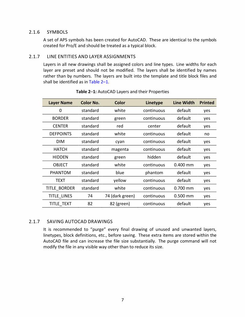
2.1.7 LINE ENTITIES AND LAYER ASSIGNMENTS
Layers in all new drawings shall be assigned colors and line types. Line widths for each
layer are preset and should not be modified. The layers shall be identified by names
rather than by numbers. The layers are built into the template and title block files and
shall be identified as in Table 2–1.
Table 2–1: AutoCAD Layers and their Properties
Layer Name Color No. Color Linetype Line Width Printed
0 standard white continuous default yes
BORDER standard green continuous default yes
CENTER standard red center default yes
DEFPOINTS standard white continuous default no
DIM standard cyan continuous default yes
HATCH standard magenta continuous default yes
HIDDEN standard green hidden default yes
OBJECT standard white continuous 0.400 mm yes
PHANTOM standard blue phantom default yes
TEXT standard yellow continuous default yes
TITLE_BORDER standard white continuous 0.700 mm yes
TITLE_LINES 74 74 (dark green) continuous 0.500 mm yes
TITLE_TEXT 82 82 (green) continuous default yes
2.1.7 SAVING AUTOCAD DRAWINGS
It is recommended to “purge” every final drawing of unused and unwanted layers,
linetypes, block definitions, etc., before saving. These extra items are stored within the
AutoCAD file and can increase the file size substantially. The purge command will not
modify the file in any visible way other than to reduce its size.
8
CHAPTER 3: PRO/E PRACTICES
3.0 INTRODUCTION Because Pro/E is a parametric 3D modeling software package, considerable time must
be taken to develop a plan before beginning. A good model is a simple one with a
minimum number of features that can be easily modified. Even more important, the
structure of a part or assembly model should be quickly understandable by any designer
who has to work with it. The following are basic guidelines for creating models with
these goals in mind.
3.1 PRO/E MODELING AND DIMENSIONING
3.1.1 FUNCTIONAL DIMENSIONING
Functional dimensioning should be used to minimize the creation of additional
dimensions when making a drawing. Limited use of ‘created’ dimensions on a drawing is
acceptable.
3.1.2 MODEL DIMENSIONS
As the APS continues to fabricate more parts directly from the model, it is very
important that the dimension scheme within the model matches that of the drawing. It
is critical to incorporate in the model significant digits, tolerances, and notes that
include dimensions. Dimensioning features from surfaces creates a more robust and
flexible model.
3.1.3 LOCATING FEATURES
The use of relations and constraints is recommended in locating features and is up to
the designer’s discretion. This allows for future modifications of the part size without
affecting the feature location.
3.1.4 MINIMIZE DATUM PLANES
Excessive use of datum planes creates clutter and complicates a model structure.
Minimize the use of datum planes through relationships and constraints unless
absolutely necessary. With the implementation of Wildfire, the added ability to embed
datum features within model features reduces the clutter. These datum features are
serviceable in the model tree as references for other model features but remain hidden
in the graphics window.
9
3.2 GENERAL PRO/E RULES
3.2.1 STARTING A NEW MODEL
A new model may be started from a Windchill/Vault workspace or within Pro/E directly.
Both methods use the APS ‘start part,’ which gives designers a standard set of planes,
views, and layers. Designers should not make new parts from within assemblies unless
the copy-from-existing choice is used. New parts made this way are almost completely
empty. These new parts are not copies of the APS ‘start part.’ Do not alter the basic
component definitions or names as they allow for consistency between designers when
files are exchanged; the exception is renaming one of the orthographic planes to a
geometric tolerancing datum. Additional views or planes may be created if necessary.
3.2.2 CENTERLINE SYMMETRY
Centerline symmetry (modeling practice: mirroring geometry) is a perfectly acceptable
means of dimensioning for relatively simple parts. One can find the symbol on the
Drawing Palette.
3.2.3 SKELETONS
Skeletons are special Pro/E part files whose sole purpose is to provide a framework for
the assembly to which they belong. (Skeleton part files must be filtered out of drawing
BOM tables as they do not represent a physical contribution to the assemblies.) They
can contain datums, curves, axes, surfaces, points and even regular model geometry,
although it is not recommended to make solid geometry (protrusions, revolves, etc.) in
skeletons. Designers are encouraged to use assembly skeleton geometry as component-
to-assembly references, as opposed to using component-to-component references.
While it’s practically impossible to avoid making such references, this practice minimizes
assembly errors where subcomponent modifications may change or erase features that
were used as references in the upper-level assembly.
3.2.4 SUPPRESS, FREEZE AND SIMPLIFIED REPRESENTATIONS
Do not save a part or assembly with suppressed or frozen components. It is very
difficult to share models and use subassemblies with suppressed parts in higher-level
assemblies. The use of simplified representations can eliminate the need for
suppressing or freezing but should also be used with caution. The name of a simplified
representation should give a clear and obvious idea what it represents to anyone
opening the file.
3.2.5 COSMETIC THREADS
The use of cosmetic threads on parts including fasteners should be held to a minimum.
10
3.2.6 WELDMENTS
It is recommended that weldments are created as they would be fabricated. The
weldment should be an assembly made of parts as opposed to one single, individual
part. Although the file size of a weldment assembly will be larger than that of a single
part, in a drawing the weldment will be represented properly with the correct number
of joints. Weldments that are made as a single part can be misleading since they look
like extrusions with no weld joints at all.
Following the rules for documenting weldments can also make it easier for locating and
releasing files. The three basic rules are:
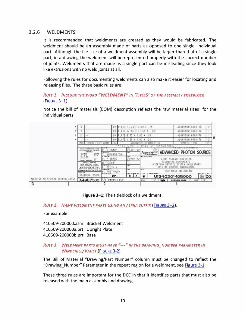
RULE 1. INCLUDE THE WORD “WELDMENT” IN ‘TITLE5’ OF THE ASSEMBLY TITLEBLOCK
(FIGURE 3–1).
Notice the bill of materials (BOM) description reflects the raw material sizes for the
individual parts
Figure 3–1: The titleblock of a weldment.
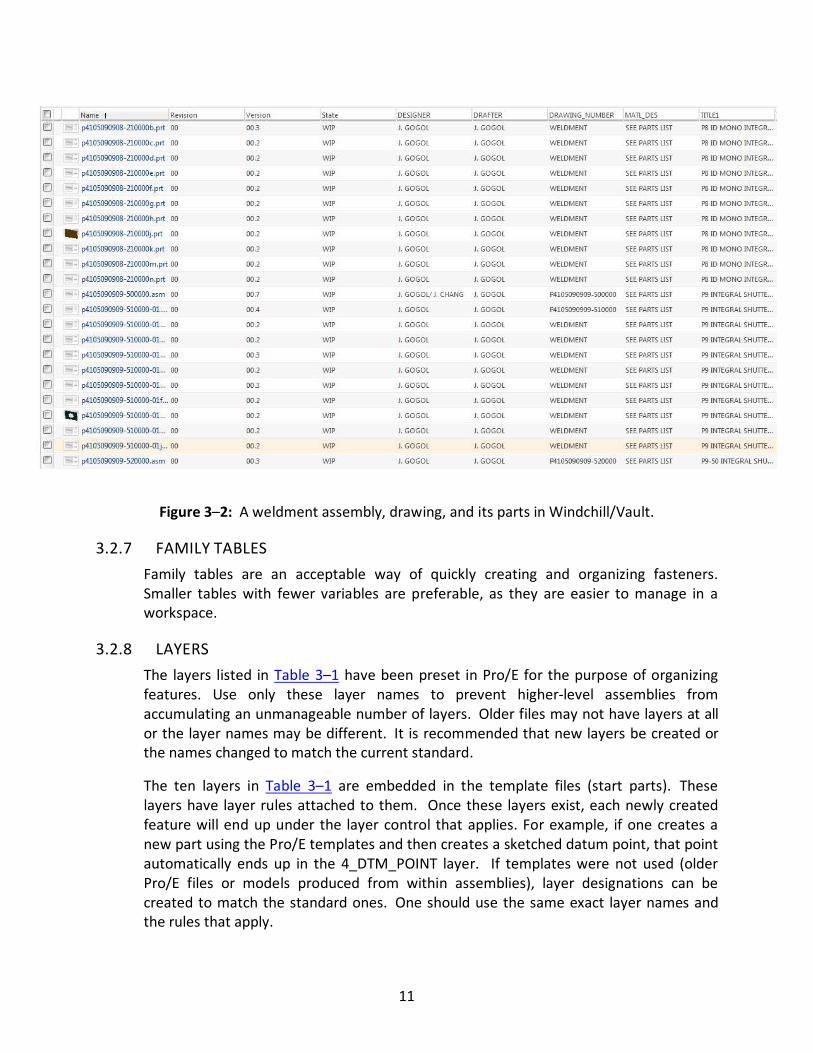
RULE 2. NAME WELDMENT PARTS USING AN ALPHA SUFFIX (FIGURE 3–2).
For example:
410509-200000.asm Bracket Weldment
410509-200000a.prt Upright Plate
410509-200000b.prt Base
RULE 3. WELDMENT PARTS MUST HAVE “---” IN THE DRAWING_NUMBER PARAMETER IN
WINDCHILL/VAULT (FIGURE 3-2).
The Bill of Material “Drawing/Part Number” column must be changed to reflect the
“Drawing_Number” Parameter in the repeat region for a weldment, see Figure 3-1.
These three rules are important for the DCC in that it identifies parts that must also be
released with the main assembly and drawing.
11
Figure 3–2: A weldment assembly, drawing, and its parts in Windchill/Vault.
3.2.7 FAMILY TABLES
Family tables are an acceptable way of quickly creating and organizing fasteners.
Smaller tables with fewer variables are preferable, as they are easier to manage in a
workspace.
3.2.8 LAYERS
The layers listed in Table 3–1 have been preset in Pro/E for the purpose of organizing
features. Use only these layer names to prevent higher-level assemblies from
accumulating an unmanageable number of layers. Older files may not have layers at all
or the layer names may be different. It is recommended that new layers be created or
the names changed to match the current standard.
The ten layers in Table 3–1 are embedded in the template files (start parts). These
layers have layer rules attached to them. Once these layers exist, each newly created
feature will end up under the layer control that applies. For example, if one creates a
new part using the Pro/E templates and then creates a sketched datum point, that point
automatically ends up in the 4_DTM_POINT layer. If templates were not used (older
Pro/E files or models produced from within assemblies), layer designations can be
created to match the standard ones. One should use the same exact layer names and
the rules that apply.
12
Note: Designers are encouraged to “Hide” datum planes and axes Layers before final
check-in .
Table 3–1: Pro/E Present Layer Names
Layer Name Member Description
12_DIMENSION all dimensions
13_THREADS cosmetic threads and hole-feature threads
1_DTM_PLANE all datum planes
2_AXIS all features containing axes
3_COORD_SYS all coordinate systems
4_DTM_POINT all points
5_SURFACES all surfaces
6_CURVES all datum curve features
7_NOTES all notes
9_GTOL geometric dimensioning and tolerancing symbols
3.2.9 RELATIONS
Relations are user-defined equations written between symbolic dimensions and
parameters. They are a way of capturing design knowledge and intent and thus are a
very powerful feature of Pro/E. Designers should take advantage of relations when
appropriate. The observance of the following rules will help make it easier to share files
with relations among designers.
1. Give key dimensions relevant names.
e.g., d23 (the length of a key feature) can be renamed to length
2. Use comments to explain your calculations. Comment lines start with “/*” which
signals to ProE to ignore anything following.
e.g., d13=length/2
/* bolt hole centered lengthwise on base plate
NOTE: If relations are sorted, comments will not stay near the calculations they describe!
13
CHAPTER 4: DIMENSIONING &
TOLERANCING
4.0 INTRODUCTION Rules and guidelines for dimensioning and tolerancing are intended to establish uniform
practices for specifying and interpreting design requirements. As a rule, all APS
drawings shall comply with ASME 1994, “Dimensioning and Tolerancing,” in its entirety.
If there is a conflict, the rules given in this section shall take precedence.
4.1 DIMENSIONING Whether in AutoCAD or Pro/E, dimensioning of parts must convey enough information
to define clearly the engineering design intent. No scaling of drawings or assumptions
should be necessary. Functional dimensioning is the preferred method.
REMEMBER BASIC DIMENSIONING RULES:
� Place dimensions on the view that most clearly explains the feature being
dimensioned.
� Place dimensions outside of the part boundaries.
� No dimensioning to hidden lines.
� Avoid dimensions that require additional calculations.
4.1.1 ASSOCIATIVE DIMENSIONING
ALL DIMENSIONS MUST BE ASSOCIATIVE REGARDLESS OF SOFTWARE USED!!
4.1.2 MANUFACTURING METHOD
The finished part should be defined without specifying the manufacturing method. Thus
only the diameter of a hole is given without specifying how it is to be produced;
“drilled,” “tapped,” etc. are not to be used.
4.1.3 DIMENSION UNITS
The preferred primary dimensioning unit is inches with millimeters shown as reference,
but millimeters may be used as primary, if applicable. It is preferable to show both
units; however, one unit only is acceptable, if applicable. In all cases the secondary unit
must become the reference unit and is shown in brackets. A note explaining the
reference unit is shown in Figure 4–1. When shown side by side, the millimeter value
typically has one less significant digit than the inch value for equivalent accuracy. The
14
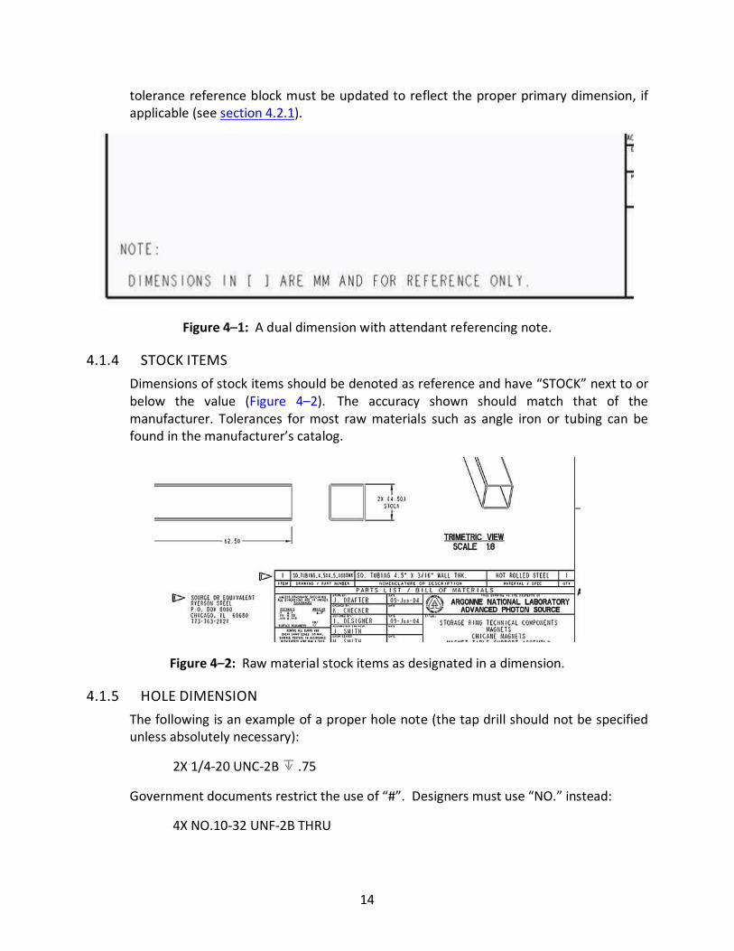
tolerance reference block must be updated to reflect the proper primary dimension, if
applicable (see section 4.2.1).
Figure 4–1: A dual dimension with attendant referencing note.
4.1.4 STOCK ITEMS
Dimensions of stock items should be denoted as reference and have “STOCK” next to or
below the value (Figure 4–2). The accuracy shown should match that of the
manufacturer. Tolerances for most raw materials such as angle iron or tubing can be
found in the manufacturer’s catalog.
Figure 4–2: Raw material stock items as designated in a dimension.
4.1.5 HOLE DIMENSION
The following is an example of a proper hole note (the tap drill should not be specified
unless absolutely necessary):
2X 1/4-20 UNC-2B .75
Government documents restrict the use of “#”. Designers must use “NO.” instead:
4X NO.10-32 UNF-2B THRU
15
4.2 TOLERANCING
4.2.1 TITLE BLOCK TOLERANCING
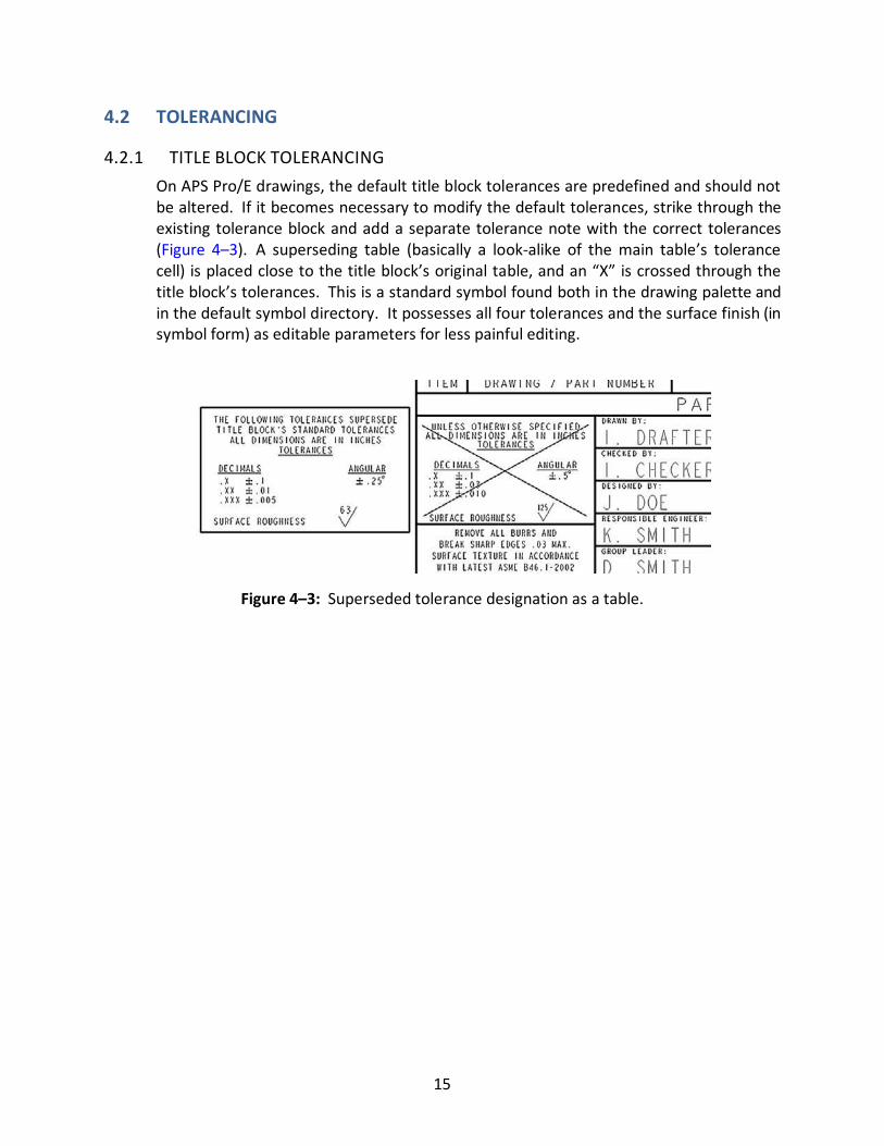
On APS Pro/E drawings, the default title block tolerances are predefined and should not
be altered. If it becomes necessary to modify the default tolerances, strike through the
existing tolerance block and add a separate tolerance note with the correct tolerances
(Figure 4–3). A superseding table (basically a look-alike of the main table’s tolerance
cell) is placed close to the title block’s original table, and an “X” is crossed through the
title block’s tolerances. This is a standard symbol found both in the drawing palette and
in the default symbol directory. It possesses all four tolerances and the surface finish (in
symbol form) as editable parameters for less painful editing.
Figure 4–3: Superseded tolerance designation as a table.
16
CHAPTER 5: WINDCHILL/PDMLINK
5.0 GENERAL INFORMATION Windchill/PDMLink is the database software used at the APS for managing Pro/Engineer
CAD data. The database controls all versions and revisions of engineering designs and
prevents them from being accidentally modified or deleted. For detailed information on
PDMLINK and how to use it, see the PDMLINK training manual or the online E-Learning
section.
Note: All engineering models and drawings created by Pro/Engineer should be worked on
within the context of PDMLink.

17
CHAPTER 6: VAULT
6.0 INTRODUCTION Vault is the database software used at the APS for managing AutoCAD data. The
database controls all versions and revisions of engineering designs and prevents them
from being accidentally modified or deleted. For detailed information on Vault and how
to use it, see the Vault training manual or the online help section.
Note: All engineering models and drawings created with AutoCAD or Inventor should be
worked on within the context of Vault.
18
CHAPTER 7: PURCHASED PARTS
7.0 INTRODUCTION This section covers the use of purchased parts in APS drawings and models. There are
many purchased parts used at the APS including fasteners, pneumatic cylinders, fittings,
electrical components, etc.
7.1 SUSPECT/CO UNTERFEIT PURCHASED PARTS
7.1.1 GENERAL INFORMATION
The U.S. Department of Energy and Argonne National Laboratory are involved in a joint
effort to keep suspect or counterfeit purchased parts and materials from being
incorporated into APS components and systems.
Note: Suspect/counterfeit purchased parts and materials are those that have been
deemed not to meet the strict standards and quality level required at the APS.
These parts pose a great threat to the safe operation of the APS in part because it
requires a trained eye to detect them. They most often are seen in the form of common
fasteners such as bolts, nuts, and washers and have a ‘normal’ looking appearance. A
list of suspect/counterfeit parts will be provided to the successful bidder of goods and
services. The awarded seller of items and services to the APS must assure that none of
the indicated suspect/counterfeit parts and materials are incorporated or installed on or
within components or equipment.
7.1.2 SUSPECT/COUNTERFEIT PARTS WARNING
A fastener requirement note should be included at the time of procurement detailing
the drawing, specifications, statement of work, or general instructions. The following is
an example of such a note.
NOTE: THIS DRAWING AND APPLICATION REQUIRES THE USE OF HIGH-STRENGTH
FASTENERS SUCH AS GRADE 5 OR GRADE 8 BOLTS. IN AN EFFORT TO PREVENT THE
INTRODUCTION OF SUSPECT OR COUNTERFEIT PARTS INTO APS COMPONENTS, A LIST
DENOTING UNFAVORABLE FASTENER MANUFACTURERS WILL BE PROVIDED BY ANL/APS
PROCUREMENT. THE SUSPECT AND COUNTERFEIT FASTENERS, AS NOTED BY THEIR HEAD
MARKINGS, ARE NOT TO BE USED IN THE CONSTRUCTION OR INSTALLATION OF ITEMS
IDENTIFIED WITHIN THIS DRAWING.
19
7.2 FASTENERS
7.2.1 PRO/E FASTENER LIBRARY
An extensive library of fastener models now exists in the Windchill/Vault databases.
Using Windchill/Vault’s search capabilities, fasteners can easily be found by part
number, material, size, and other search parameters. Although the majority of
fasteners commonly used in assembling components already exist, this in no way should
restrict the use of other materials or types where design issues deem them necessary.
Steps for creating new purchased parts are outlined later in this chapter.
7.2.2 FASTENER VENDORS
When selecting a common fastener the following vendors should be given priority in the
order they are listed.
1. McMaster-Carr
2. Grainger
3. Argonne Stockroom
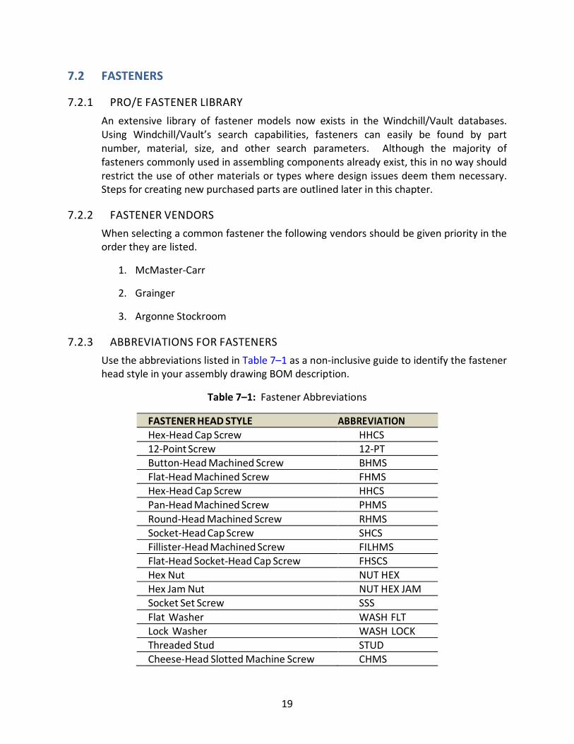
7.2.3 ABBREVIATIONS FOR FASTENERS
Use the abbreviations listed in Table 7–1 as a non-inclusive guide to identify the fastener
head style in your assembly drawing BOM description.
Table 7–1: Fastener Abbreviations
FASTENER HEAD STYLE ABBREVIATION
Hex-Head Cap Screw HHCS
12-Point Screw 12-PT
Button-Head Machined Screw BHMS
Flat-Head Machined Screw FHMS
Hex-Head Cap Screw HHCS
Pan-Head Machined Screw PHMS
Round-Head Machined Screw RHMS
Socket-Head Cap Screw SHCS
Fillister-Head Machined Screw FILHMS
Flat-Head Socket-Head Cap Screw FHSCS
Hex Nut NUT HEX
Hex Jam Nut NUT HEX JAM
Socket Set Screw SSS
Flat Washer WASH FLT
Lock Washer WASH LOCK
Threaded Stud STUD
Cheese-Head Slotted Machine Screw CHMS
20
Example BOM descriptions (Title5):
SHCS 1/4-20 UNC-2A X 1.00 LG WASH FLT .50 X 1.25 X .10 THK NUT HEX JAM
5/16-18 UNC-2B
FILHMS NO.6 (.138)-32 UNC-2A X 1.50 LG STUD 3/8-16 UNC-1A X 5.00 LG FULL
THRD
RHMS NO.4 (.112)-40 UNC-2A X .25 LG(PHILLIPS)
Three rules for fastener’s Title5 parameter:
1. Fastener size shall be fractional:
1/4-20… , 5/16-18… , 3/8-16…
2. Fastener length shall be decimal:
…X .25 LG, …X 1.50 LG, …X 1.00 LG
3. Metric fasteners shall take the following format:
M10 X 25
The designation of “mm” is assumed and not necessary.
7.3 VACUUM COMPONENTS Many common vacuum components such as Conflat flanges, ion pumps, and valves also
exist in a vacuum component library in Windchill/Vault. Searching by model number,
vendor, or description can easily locate an item.
7.3.1 MODELING PRACTICES - GASKETS AND FASTENERS
The inclusion of flange gaskets and hardware in an assembly model is recommended but
not required. Although it is preferred to have a complete BOM for ordering purposes,
the inclusion of gaskets or fasteners on a larger assembly such as an entire front end can
take a significant amount of time and reduce assembly performance. Family tables of
both these vacuum hardware components exist in the Windchill/Vault library but should
be used on a case-by-case basis. If they are included, a simplified representative must be
made to remove them easily at a later date.
7.3.2 MODELING PRACTICES - PUMPS, VALVES, ETC.
Vacuum pumps, gate valves, and other vacuum components are purchased with a
variety of options. It is important not only to know the nominal size of the item but the
list of options required as well. Using a model that is accurate in detail and size can help
prevent any interference between a connection and a support or neighboring
component. Typically, these options are included in the specific part number, which can
21
be obtained from the purchase order list of vacuum components. The project engineer
should be able to supply this list upon request.
7.4 MISCELLANEOUS COMPONENTS Although not nearly as numerous as fasteners, there are many miscellaneous purchased
parts existing as models in Windchill/Vault. Figure 7–1 shows examples such as
pneumatic cylinders, hydraulic fittings, and electrical components.
Figure 7–1: Examples of miscellaneous components.
7.5 USING PURCHASED PART MODELS All purchased parts that exist within the Windchill/Vault purchased part library are
write- protected. As such, they can be used within assemblies but cannot be modified in
any way. If there is an error in geometry or part parameter (e.g., item description,
material, vendor, etc.), please ask a library administrator to make a correction.
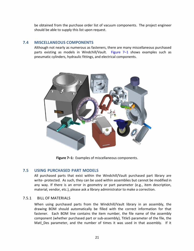
7.5.1 BILL OF MATERIALS
When using purchased parts from the Windchill/Vault library in an assembly, the
drawing BOM should automatically be filled with the correct information for that
fastener. Each BOM line contains the item number, the file name of the assembly
component (whether purchased part or sub-assembly), Title5 parameter of the file, the
Matl_Des parameter, and the number of times it was used in that assembly. If it
22
becomes necessary to edit the contents of a BOM field, the task is accomplished by
changing the offending parameters in the component part (or by renaming the file in
the case of the Model Name) (see Figure 7–2). It is not acceptable to leave the
purchased part’s material description (Matl_Des) parameter blank. If the component is
a heterogeneous mishmash of several materials, the word “VARIOUS” or “PURCHASED”
is acceptable.
Figure 7–2: A typical BOM table.
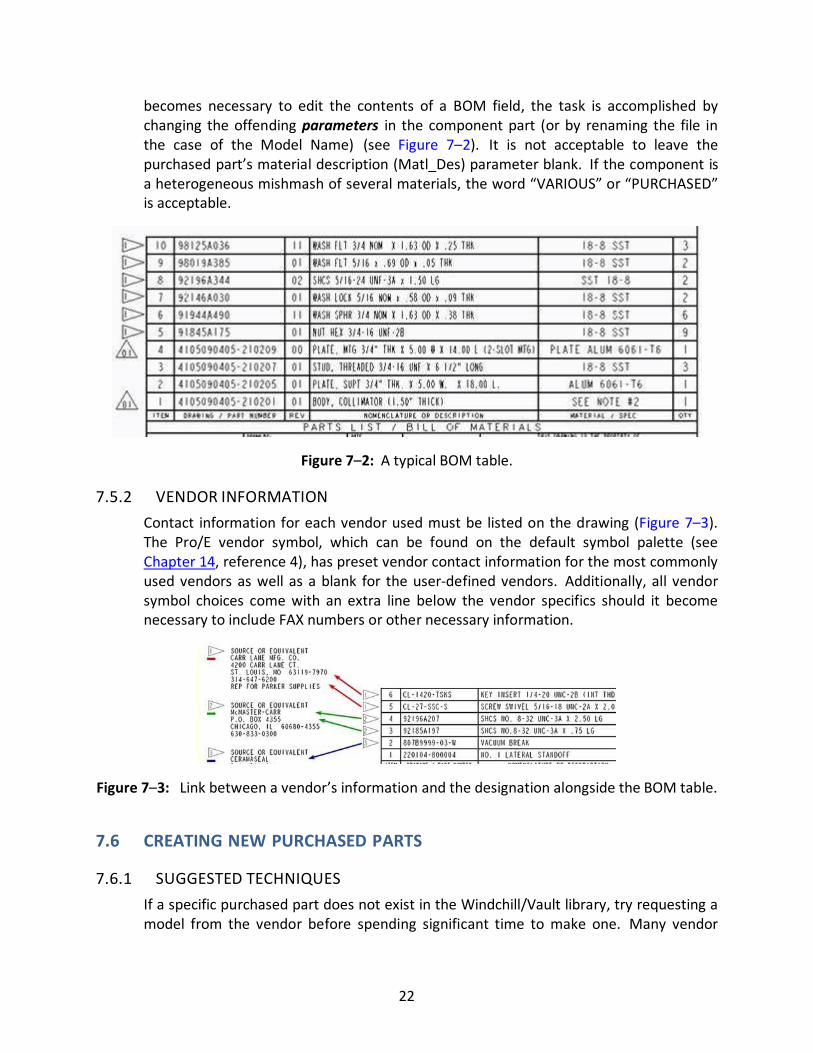
7.5.2 VENDOR INFORMATION
Contact information for each vendor used must be listed on the drawing (Figure 7–3).
The Pro/E vendor symbol, which can be found on the default symbol palette (see
Chapter 14, reference 4), has preset vendor contact information for the most commonly
used vendors as well as a blank for the user-defined vendors. Additionally, all vendor
symbol choices come with an extra line below the vendor specifics should it become
necessary to include FAX numbers or other necessary information.
Figure 7–3: Link between a vendor’s information and the designation alongside the BOM table.
7.6 CREATING NEW PURCHASED PARTS
7.6.1 SUGGESTED TECHNIQUES
If a specific purchased part does not exist in the Windchill/Vault library, try requesting a
model from the vendor before spending significant time to make one. Many vendor
23
websites offer 2D or 3D part models for download while some vendors will supply a
complete model in a generic file format, such as STEP, upon request.
Note: Vendor files can be very complex and large. ‘Shrinkwrap’ assemblies at moderate
quality level whenever possible. See the CAD administrator for help with this process.
When it is absolutely necessary to make a new model, purchased parts should consist of
simplified geometry and use a minimum number of features. The easiest way to create
a new purchased part is to duplicate a similar existing model and modify it accordingly.
Using a part from the same vendor eliminates the need to re-enter vendor information
into the part parameters. It is also important to select a well-modeled part to duplicate.
Some older purchased parts lack the standard planes and layers or use unnecessary and
complicated features and should be avoided.
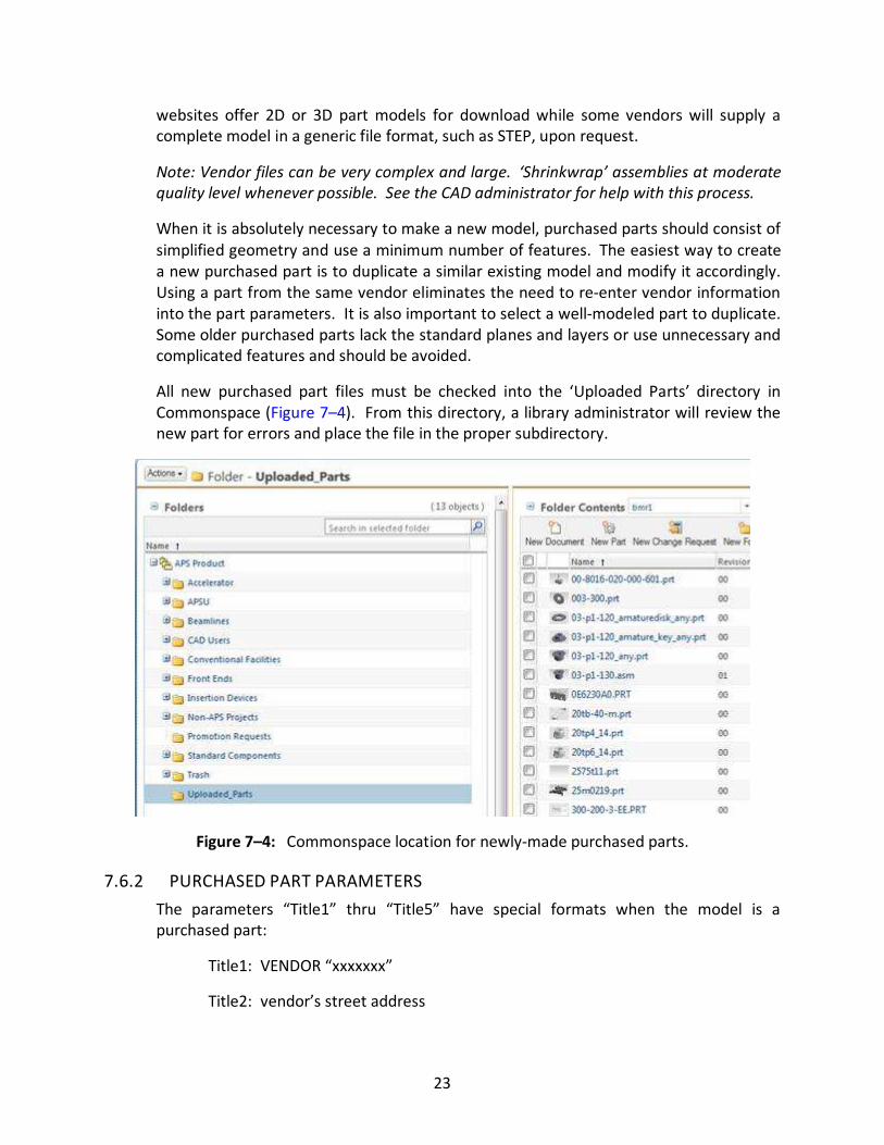
All new purchased part files must be checked into the ‘Uploaded Parts’ directory in
Commonspace (Figure 7–4). From this directory, a library administrator will review the
new part for errors and place the file in the proper subdirectory.
Figure 7–4: Commonspace location for newly-made purchased parts.
7.6.2 PURCHASED PART PARAMETERS
The parameters “Title1” thru “Title5” have special formats when the model is a
purchased part:
Title1: VENDOR “xxxxxxx”
Title2: vendor’s street address
24
Title3: vendor’s city, state, and zip code
Title4: vendor’s phone number xxx-xxx-xxxx
Title5: Proper description of the modeled part. (SHCS, 1/4 -20 x 1.500 in.) As
discussed previously, see section 7.2.3 for examples of acceptable part
descriptions
7.6.3 FAMILY TABLES
Family tables are an acceptable way of quickly creating and modifying a series of related
purchased parts. They allow quick replacement of parts within an assembly but are
notorious for causing problems among users in Windchill/Vault if certain rules are not
followed. Care must be taken when creating new purchased parts. Do not duplicate
family table generics or instances. These special files can be identified in Windchill/Vault
and also should be avoided. Ask a library administrator for assistance with any family
table issues.
SUMMARY OF STEPS TO CREATE NEW PURCHASED PARTS
� Query the Windchill/Vault database for the required purchased part.
� If the part does not exist in Windchill/Vault, search again for related parts by
using only a portion of the part number with the Windchill/Vault wildcard ‘*’.
� Duplicate a related file or create a completely new model. Verify geometry and
all part and vendor parameters.
� Check in to Commonspace.
� Inform a library administrator and provide with any specs or drawings necessary to
check the new model.
Note: Always consider asking a vendor if they can supply a 3D model for more
complicated parts.
25
CHAPTER 8: VACUUM STANDARDS
8.0 INTRODUCTION This section is intended to give readers a basic understanding of ultra-high vacuum
(UHV) systems and practices at APS for the purpose of creating UHV component
drawings. Examples of UHV component drawings are shown but specific notes and
values should not be assumed to be standard for any component. All UHV questions to
be directed to an APS vacuum engineer.
8.1 VACUUM BASICS Vacuum (def.): A space completely devoid of matter. [Merriam-Webster dictionary]
A complete vacuum would occur if every single gas molecule, atom, ion, etc. from a
given container were removed. It is impossible, however, to do this, so a vacuum is
considered to occur when the pressure drops below normal atmospheric pressure (i.e.,
1 Atm or 101,325 Pa or 760 Torr).
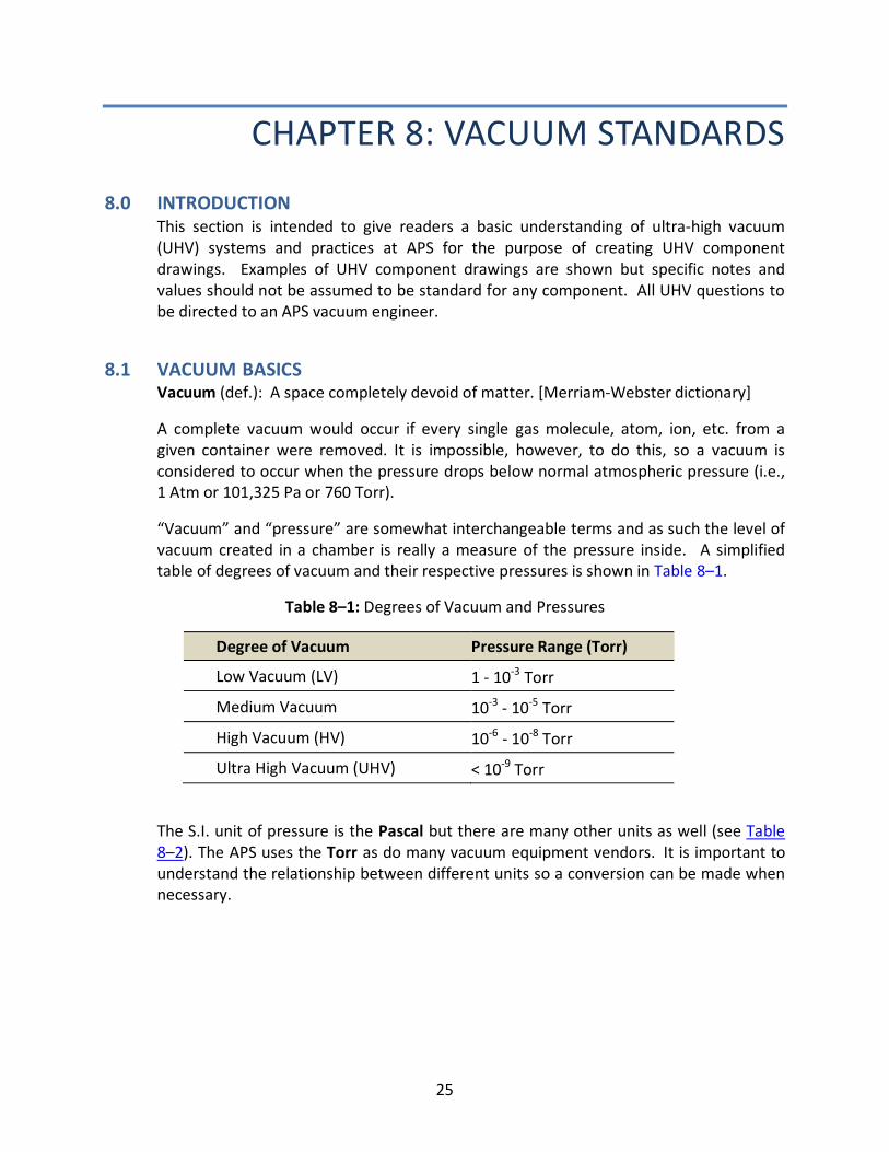
“Vacuum” and “pressure” are somewhat interchangeable terms and as such the level of
vacuum created in a chamber is really a measure of the pressure inside. A simplified
table of degrees of vacuum and their respective pressures is shown in Table 8–1.
Table 8–1: Degrees of Vacuum and Pressures
Degree of Vacuum Pressure Range (Torr)
Low Vacuum (LV) 1 - 10-3 Torr
Medium Vacuum 10-3 - 10-5 Torr
High Vacuum (HV) 10-6 - 10-8 Torr
Ultra High Vacuum (UHV) < 10-9 Torr
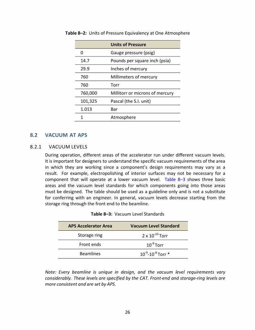
The S.I. unit of pressure is the Pascal but there are many other units as well (see Table
8–2). The APS uses the Torr as do many vacuum equipment vendors. It is important to
understand the relationship between different units so a conversion can be made when
necessary.
26
Table 8–2: Units of Pressure Equivalency at One Atmosphere
Units of Pressure
0 Gauge pressure (psig)
14.7 Pounds per square inch (psia)
29.9 Inches of mercury
760 Millimeters of mercury
760 Torr
760,000 Millitorr or microns of mercury
101,325 Pascal (the S.I. unit)
1.013 Bar
1 Atmosphere
8.2 VACUUM AT APS
8.2.1 VACUUM LEVELS
During operation, different areas of the accelerator run under different vacuum levels.
It is important for designers to understand the specific vacuum requirements of the area
in which they are working since a component’s design requirements may vary as a
result. For example, electropolishing of interior surfaces may not be necessary for a
component that will operate at a lower vacuum level. Table 8–3 shows three basic
areas and the vacuum level standards for which components going into those areas
must be designed. The table should be used as a guideline only and is not a substitute
for conferring with an engineer. In general, vacuum levels decrease starting from the
storage ring through the front end to the beamline.
Table 8–3: Vacuum Level Standards
APS Accelerator Area Vacuum Level Standard
Storage ring 2 x 10⁻¹⁰ Torr
Front ends 10-9 Torr
Beamlines 10-9-10-8 Torr *
Note: Every beamline is unique in design, and the vacuum level requirements vary
considerably. These levels are specified by the CAT. Front-end and storage-ring levels are
more consistent and are set by APS.
27
The vacuum level standards are always higher than achievable operating levels that are
affected by a number of factors. The mere presence of a 100-mA beam along with
general outgassing often reduces the vacuum by a factor of ten. This is, however,
compensated slightly by the fact that, all things being equal, vacuum levels generally
increase with time.
“Outgassing” - The release of molecules and atoms by a material over time. The rate of
release over time is the “outgassing rate” (liters/second).
8.2.2 EFFECTS OF VACUUM ON THE BEAM
Ordinary sea level air, very simply, has too many gas molecules, atoms, ions, etc., for
electrons—which comprise the beam—to be accelerated efficiently through it. Removal
of these molecules, etc. by creating an ultrahigh vacuum not only clears a path for the
electrons but reduces dangerous secondary scattering effects such as bremsstrahlung
radiation.
Bremsstrahlung radiation (German translation: “braking radiation”) is simply the energy
lost (i.e., radiation emitted) by a high-energy electron as it decelerates due to
interaction with atomic nuclei.
Bremsstrahlung radiation is very dangerous for two reasons. First the wavelength of the
radiation emitted by the colliding electrons is dependent upon the initial electron
energy. At the APS, bremsstrahlung radiation is in the form of hard x- rays, which are
the highest energy and most penetrating x-rays. Secondly, since bremsstrahlung
radiation is a scattering phenomenon, the direction of the resultant x-rays is
unpredictable and should be assumed to be present at any angle.
8.3 UHV DESIGN CONSIDERATIONS When designing components of a UHV system, it is critical that every aspect of the
design and fabrication method be specially considered. Improper design, fabrication
and handling of a UHV component can result in virtual leaks, unacceptable outgassing,
and even contamination of an entire section of connected components, making a UHV
level vacuum impossible in a reasonable amount of time.
Note: The key of good UHV design is to reduce outgassing and virtual leaks.
8.3.1 MATERIALS
There are a limited number of materials that are acceptable for use in a UHV system.
Stainless steel, aluminum, and ceramics are the most common and inexpensive. The
primary characteristic of these materials that make them appropriate for use in a UHV
vacuum is their low outgassing rates.
Outgassing has two main sources:
28
1. Internal Structure - All commercial metals have some amount of gas trapped
within their internal structures as a result of the formation process. The
“outgassing rate” is a measure of this source only.
2. Surface Impurities - A second source of outgassing is the evaporation of oil, dirt,
or any other foreign substance from a material’s surface as the pressure is
reduced. It is the result of this source that all UHV components must be
extremely clean at installation.
8.3.2 SURFACE TEXTURE
The effect of surface texture on pumping speeds is debated by vacuum engineers
worldwide. Some engineers believe that a rough surface increases the overall surface
area and the resulting layer of impurity atoms attracted to it. A better surface texture
(i.e., less surface area and fewer impurity atoms) is thought to result in a faster pumping
speed. Although this issue is debated, APS engineers generally prefer to specify a better
surface texture. As a general rule, surfaces internal to the vacuum system should be at
least 63 microinches or better. Electropolishing is necessary when a surface texture of
32 microinches or better is required.
Electropolishing is the reverse of electroplating. A DC electrolytic circuit is constructed
with the work piece as the anode. As current is applied, material is stripped from the
surface with material removal occurring preferentially from any raised location.
8.3.3 VIRTUAL LEAKS
A virtual leak is not a true leak at all. It is only the appearance of a leak that is caused by
the slow, continuous release of trapped gas into the system. The gas is actually trapped
within small spaces not fully connected to the main chamber. As the system is being
pumped down, the gas in these spaces is restricted and does not evacuate as quickly or
thoroughly as the main chamber. It can be difficult to discern a true leak from a virtual
leak since they behave the same.
Note: Virtual leaks are usually caused by poor mechanical design and can be completely
prevented.
The most common sources of virtual leaks are:
1. cracks – example: an external weld with a crack
2. small gaps – example: under a bolt head or between mating surfaces
3. trapped pockets – example: a fastener in a blind hole
To prevent a virtual leak, an alternate route for gas to escape must be supplied. This can
be accomplished a number of ways. Listed below are design rules created to help in
their prevention.
29
8.3.4 WATER-TO-VACUUM JOINTS
At the APS water-to-vacuum joints are to be avoided whenever possible. Using proper
design methods, all water joints should be vented to atmosphere to avoid
contamination of the vacuum system.
DESIGN RULES FOR PREVENTING VIRTUAL LEAKS
1. Use vented fasteners – Vented fasteners have a hole drilled completely
through the axis of the fastener. They are very common commercially
available purchased parts.
2. Drill into blind tapped holes – Blind tapped holes are notorious for
creating virtual leaks. Drilling a small hole perpendicular to the tapped
hole allows for quick escape of any gas that is trapped after inserting the
screw. A vented fastener used in combination with a drilled blind hole is
ideal.
3. Weld internal to the component chamber – External welds have a
tendency to create very small gaps and cracks. Although it may not be
possible to completely eliminate external welds, internal welding is
preferable.
8.4 UHV PRACTICES There are a number of practices that are typically used on any UHV component to
reduce outgassing. Each step in the preparation and handling of UHV components is
time consuming, so fabrication and installation lead times must be generous.
Permanent contamination of a section of accelerator components can occur by taking
shortcuts and not following APS-approved UHV procedures.
8.4.1 MACHINING FLUIDS
Cutting fluids containing silicone, sulfur, phosphorous, or halogens are unacceptable for
use on UHV components. Oil-based fluids, in general, are also unacceptable. The APS
only authorizes the use of Trimsol or an equivalent approved fluid. (See ANL
Specification Document #410201-00095 in section 8.5.3.)
It is very important that this requirement is written on any mechanical drawing of a
vacuum component that requires machining. Unless specializing in the fabrication of
vacuum components, machine shops do not necessarily use acceptable cutting fluids in
their machines. Some shops will charge a significant fee if they have to drain and clean a
machine of their standard fluid and refill with Trimsol.
30
8.4.2 CLEANING
All vacuum components undergo a thorough cleaning at APS upon assembly. Individual
parts of a weldment should be cleaned prior to welding as well as afterwards as a
weldment. Cleaning for UHV service at the APS consists of the following basic steps.
1. Component is bathed in Citrinox (acidic cleanser) solution with ultrasonic and
mechanical agitation at an elevated temperature.
2. Component is rinsed in deionized water at an elevated temperature.
3. Component is blown dry with dry nitrogen and also heated to an elevated
temperature.
After cleaning, the component should be used as soon as possible or stored properly to
keep it clean.
Note: Never touch with bare hands an internal surface of a UHV component that has
already been cleaned! The outgassing from one fingerprint can prevent a UHV vacuum
from occurring.
8.4.3 BAKEOUT
After a component is fully assembled and cleaned, it is ready for installation. In order to
remove excess moisture, a string of components at the installation site must be heated
to induce evaporation prior to the initiation of the pumpdown phase. This process is
referred to as the ‘bakeout’ phase.
8.5 UHV COMPONENT DRAWINGS
8.5.1 FLANGES
There are two customs for aligning flange mounting holes on non-rotatable flanges. The
English custom of straddling fastener holes about a vertical or horizontal plane should
be followed. The European custom, to align holes to the vertical or horizontal plane,
should be avoided (Figure 8–1).
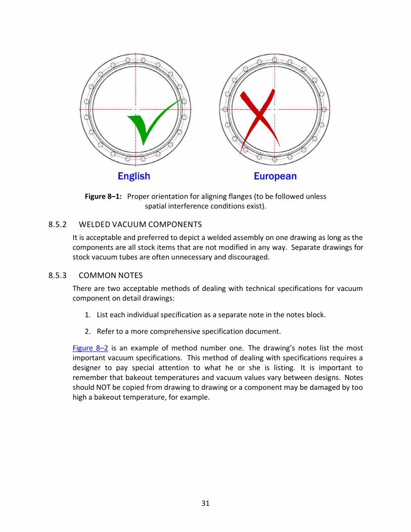
31
Figure 8–1: Proper orientation for aligning flanges (to be followed unless
spatial interference conditions exist).
8.5.2 WELDED VACUUM COMPONENTS
It is acceptable and preferred to depict a welded assembly on one drawing as long as the
components are all stock items that are not modified in any way. Separate drawings for
stock vacuum tubes are often unnecessary and discouraged.
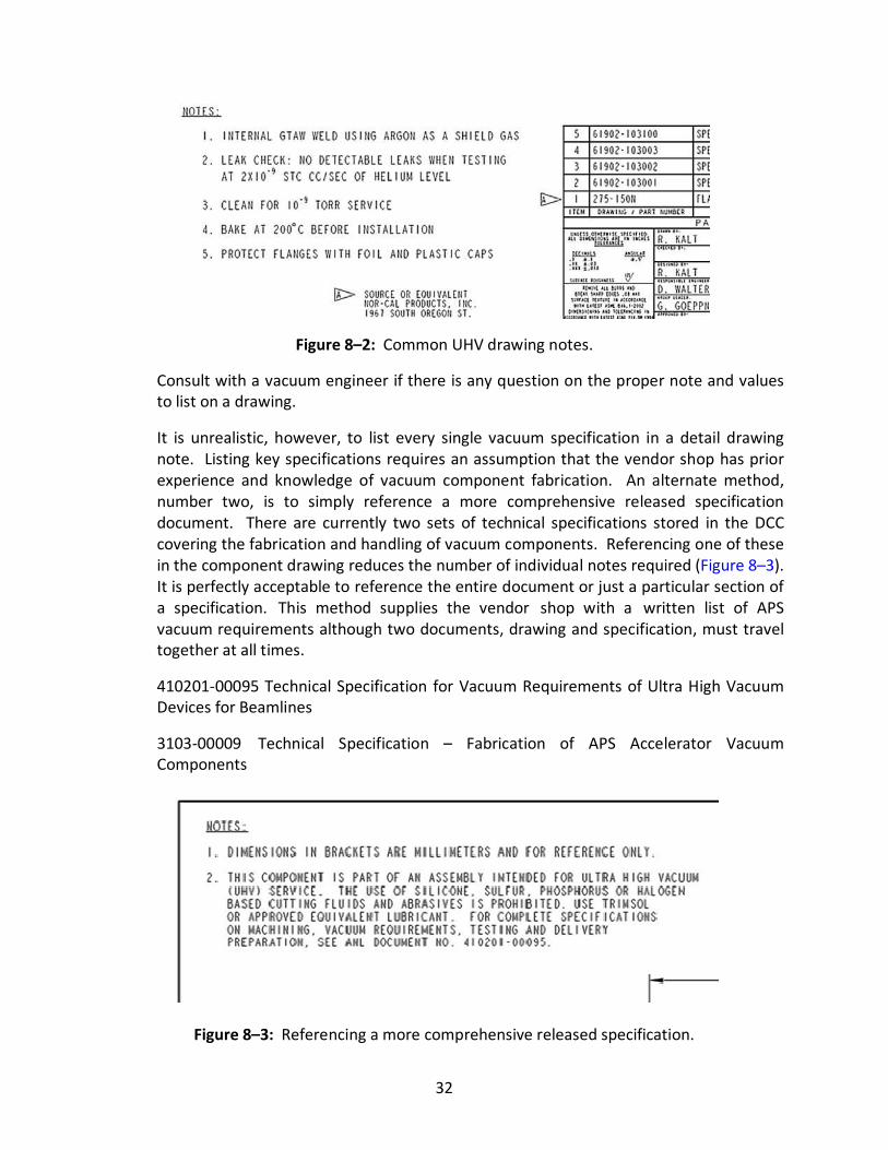
8.5.3 COMMON NOTES
There are two acceptable methods of dealing with technical specifications for vacuum
component on detail drawings:
1. List each individual specification as a separate note in the notes block.
2. Refer to a more comprehensive specification document.
Figure 8–2 is an example of method number one. The drawing’s notes list the most
important vacuum specifications. This method of dealing with specifications requires a
designer to pay special attention to what he or she is listing. It is important to
remember that bakeout temperatures and vacuum values vary between designs. Notes
should NOT be copied from drawing to drawing or a component may be damaged by too
high a bakeout temperature, for example.
32
Figure 8–2: Common UHV drawing notes.
Consult with a vacuum engineer if there is any question on the proper note and values
to list on a drawing.
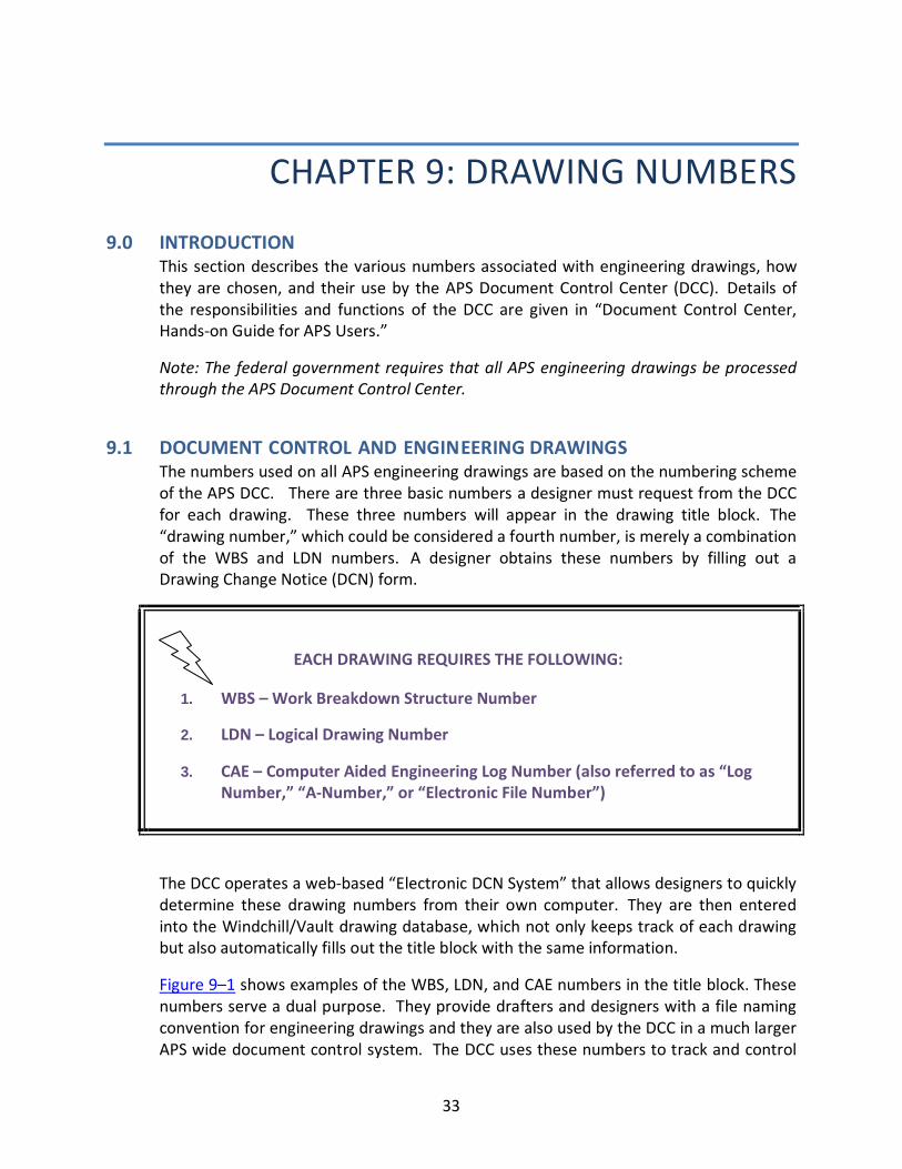
It is unrealistic, however, to list every single vacuum specification in a detail drawing
note. Listing key specifications requires an assumption that the vendor shop has prior
experience and knowledge of vacuum component fabrication. An alternate method,
number two, is to simply reference a more comprehensive released specification
document. There are currently two sets of technical specifications stored in the DCC
covering the fabrication and handling of vacuum components. Referencing one of these
in the component drawing reduces the number of individual notes required (Figure 8–3).
It is perfectly acceptable to reference the entire document or just a particular section of
a specification. This method supplies the vendor shop with a written list of APS
vacuum requirements although two documents, drawing and specification, must travel
together at all times.
410201-00095 Technical Specification for Vacuum Requirements of Ultra High Vacuum
Devices for Beamlines
3103-00009 Technical Specification – Fabrication of APS Accelerator Vacuum
Components
Figure 8–3: Referencing a more comprehensive released specification.
33
CHAPTER 9: DRAWING NUMBERS
9.0 INTRODUCTION This section describes the various numbers associated with engineering drawings, how
they are chosen, and their use by the APS Document Control Center (DCC). Details of
the responsibilities and functions of the DCC are given in “Document Control Center,
Hands-on Guide for APS Users.”
Note: The federal government requires that all APS engineering drawings be processed
through the APS Document Control Center.
9.1 DOCUMENT CONTROL AND ENGINEERING DRAWINGS The numbers used on all APS engineering drawings are based on the numbering scheme
of the APS DCC. There are three basic numbers a designer must request from the DCC
for each drawing. These three numbers will appear in the drawing title block. The
“drawing number,” which could be considered a fourth number, is merely a combination
of the WBS and LDN numbers. A designer obtains these numbers by filling out a
Drawing Change Notice (DCN) form.
EACH DRAWING REQUIRES THE FOLLOWING:
1. WBS – Work Breakdown Structure Number
2. LDN – Logical Drawing Number
3. CAE – Computer Aided Engineering Log Number (also referred to as “Log
Number,” “A-Number,” or “Electronic File Number”)
The DCC operates a web-based “Electronic DCN System” that allows designers to quickly
determine these drawing numbers from their own computer. They are then entered
into the Windchill/Vault drawing database, which not only keeps track of each drawing
but also automatically fills out the title block with the same information.
Figure 9–1 shows examples of the WBS, LDN, and CAE numbers in the title block. These
numbers serve a dual purpose. They provide drafters and designers with a file naming
convention for engineering drawings and they are also used by the DCC in a much larger
APS wide document control system. The DCC uses these numbers to track and control
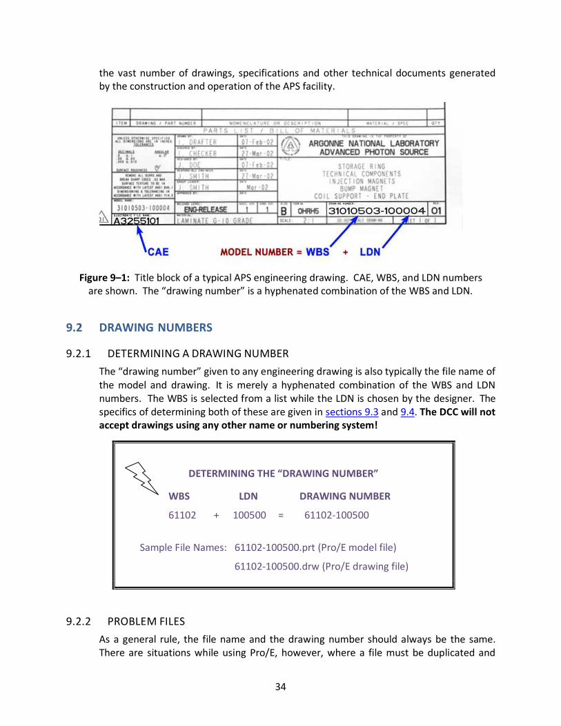
34
the vast number of drawings, specifications and other technical documents generated
by the construction and operation of the APS facility.
Figure 9–1: Title block of a typical APS engineering drawing. CAE, WBS, and LDN numbers
are shown. The “drawing number” is a hyphenated combination of the WBS and LDN.
9.2 DRAWING NUMBERS
9.2.1 DETERMINING A DRAWING NUMBER
The “drawing number” given to any engineering drawing is also typically the file name of
the model and drawing. It is merely a hyphenated combination of the WBS and LDN
numbers. The WBS is selected from a list while the LDN is chosen by the designer. The
specifics of determining both of these are given in sections 9.3 and 9.4. The DCC will not
accept drawings using any other name or numbering system!
DETERMINING THE “DRAWING NUMBER”
WBS LDN DRAWING NUMBER
61102 + 100500 = 61102-100500
Sample File Names: 61102-100500.prt (Pro/E model file)
61102-100500.drw (Pro/E drawing file)
9.2.2 PROBLEM FILES
As a general rule, the file name and the drawing number should always be the same.
There are situations while using Pro/E, however, where a file must be duplicated and
35
given a different name. One of the most common examples of this occurs when an
assembly with moveable components must be shown in two different positions in two
different higher-level assemblies. If a duplicate of any component or assembly model is
required, the original released files must be left alone and an alternate name given to
the duplicate. This will affect the bill of materials for any higher-level assembly using
the duplicate, so the item will typically have to be filtered out of the BOM and a row
with the proper component drawing number (file name) added.
The best alternate file name is made by adding an underscore to the original file name.
When multiple duplicate files are required, an underscore followed by a letter is
acceptable. Speak with the CAD supervisor if additional help is needed in selecting
appropriate alternate file names.
Alternate File Names for Duplicating Models
61102-100600.asm (Original Pro/E model file name)
61102-100600_.asm (Alternate file names)
61102-100600_a.prt
9.3 WBS NUMBERS
9.3.1 WORK BREAKDOWN STRUCTURE
The Work Breakdown Structure (WBS) is a technique or tool developed by the DOE for
project management. It provides a numerical framework for identifying technical
components and objectives in a large project such as the APS. The numerical framework
is hierarchical with each additional level or number providing further detail.
9.3.2 WBS NUMBERS
At the APS, WBS numbers are used by designers and engineers to numerically describe
components and their locations within the accelerator ring. This number is selected
from a master WBS list and then used for the first half of the drawing number (Figure 9–
2).
The WBS can be accessed through the DCC website or a paper copy can be requested by
contacting DCC directly.
Typically, designers and engineers jointly select the WBS. For smaller projects, the WBS
number can be used for most or all of the resulting drawings while larger projects will
probably require numerous WBS numbers.
36
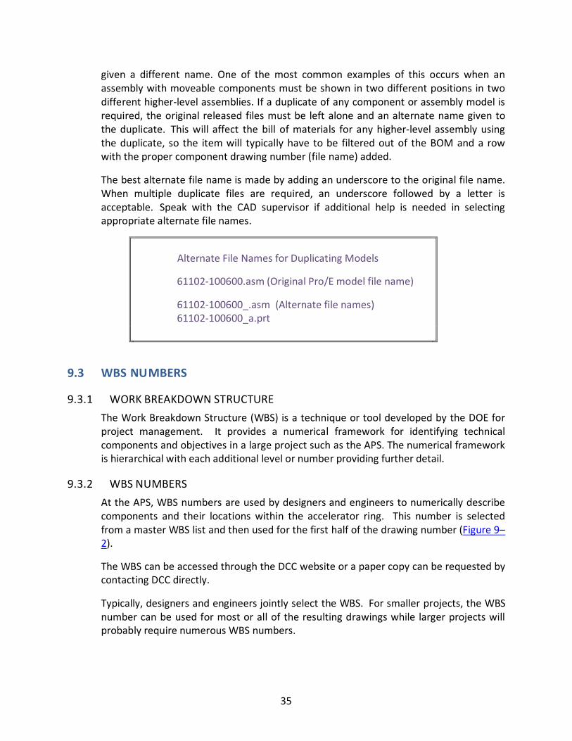
Speak with the CAD supervisor if additional help is needed in selecting appropriate WBS
numbers.
Figure 9–2: Breakdown description of a WBS number for a component in the ring.
The first ‘1’ refers to construction phase and is ignored.
Always verify the model name against the DCN drawing number. Note the
example in Figure 9–3 does not drop the second “0” since the “.30.” uses both digits;
this is common for all double-digit WBS indicators, only leading zeros are dropped with
WBS indicators.
37
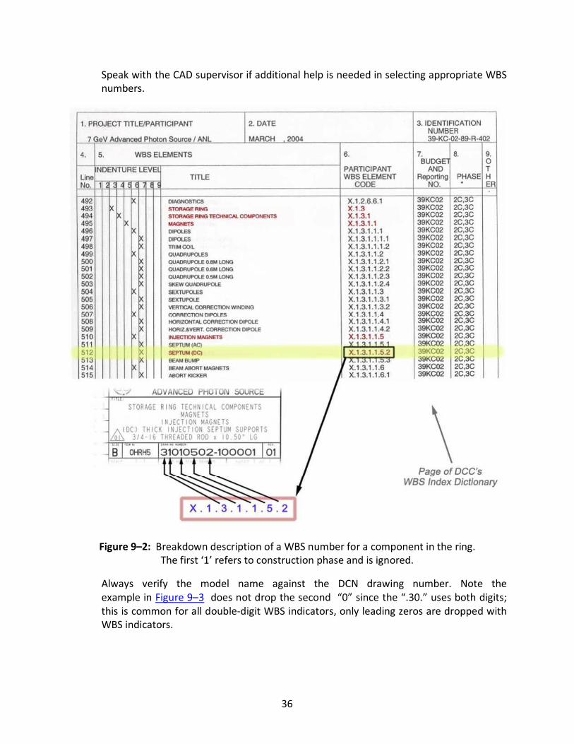
Figure 9–3: Complete document or model name versus DCN drawing number (WBS).
9.4 LDN NUMBERS
9.4.1 DESCRIPTION
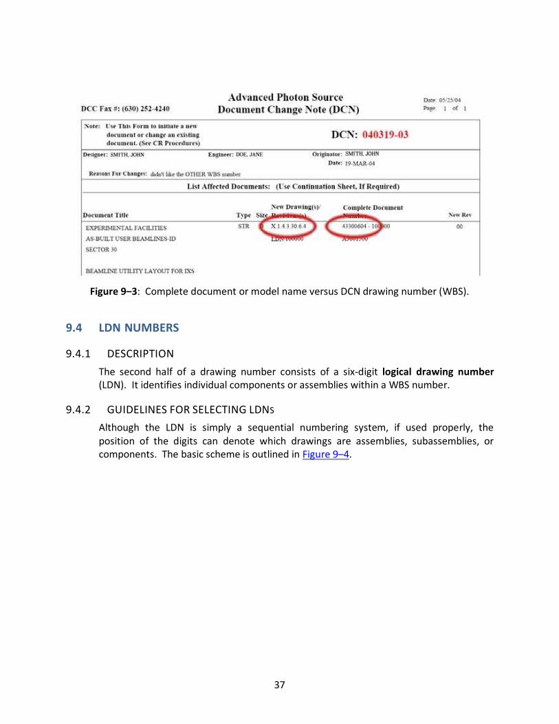
The second half of a drawing number consists of a six-digit logical drawing number
(LDN). It identifies individual components or assemblies within a WBS number.
9.4.2 GUIDELINES FOR SELECTING LDNS
Although the LDN is simply a sequential numbering system, if used properly, the
position of the digits can denote which drawings are assemblies, subassemblies, or
components. The basic scheme is outlined in Figure 9–4.
38
Figure 9–4: LDN numbering scheme.
9.4.3 USING THE ELECTRONIC DCN SYSTEM
� Query the DCC database for the availability of numbers. If an LDN within a WBS
has been taken already, you cannot reuse it for a new project.
� Try to start with the lowest numbers available and select sequential numbers for
components in the same assembly.
� Parts should be numbered in relation to assemblies.
Note: Selecting LDN’s is completely up to the designer’s discretion and should be done
carefully and with some logic! Do not block off groups by hundreds try and use tens to
define sub-assemblies and single digits for components in the sub-assembly.
39
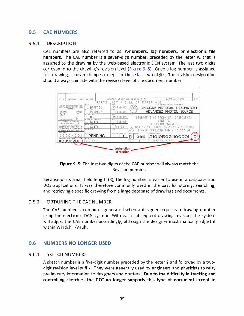
9.5 CAE NUMBERS
9.5.1 DESCRIPTION
CAE numbers are also referred to as: A-numbers, log numbers, or electronic file
numbers. The CAE number is a seven-digit number, preceded by the letter A, that is
assigned to the drawing by the web-based electronic DCN system. The last two digits
correspond to the drawing’s revision level (Figure 9–5). Once a log number is assigned
to a drawing, it never changes except for these last two digits. The revision designation
should always coincide with the revision level of the document number.
Figure 9–5: The last two digits of the CAE number will always match the
Revision number.
Because of its small field length (8), the log number is easier to use in a database and
DOS applications. It was therefore commonly used in the past for storing, searching,
and retrieving a specific drawing from a large database of drawings and documents.
9.5.2 OBTAINING THE CAE NUMBER
The CAE number is computer generated when a designer requests a drawing number
using the electronic DCN system. With each subsequent drawing revision, the system
will adjust the CAE number accordingly, although the designer must manually adjust it
within Windchill/Vault.
9.6 NUMBERS NO LONGER USED
9.6.1 SKETCH NUMBERS
A sketch number is a five-digit number preceded by the letter S and followed by a two-
digit revision level suffix. They were generally used by engineers and physicists to relay
preliminary information to designers and drafters. Due to the difficulty in tracking and
controlling sketches, the DCC no longer supports this type of document except in
40
special circumstances with the approval of the CAD supervisor. Regular engineering
drawings should be used instead.
9.6.2 PROTOTYPE NUMBERS
A prototype drawing number has the same structure as a document number except that
it starts with the letter P, indicating a prototype. This was used during the initial
construction phase of APS mainly by XFD (now XSD) when the components were in a
prototype phase. When a prototype drawing was considered to be acceptable, the
prototype drawing number was converted to the logical drawing number by dropping
the letter P and incrementing the revision number.
Note: Although some drawings still have prototype numbers, this system is no longer
used and any drawings that are being reused should be tranlated to the logical number.
41
CHAPTER 10: APPROVAL
10.0 INTRODUCTION When a drawing is complete, including a properly filled out title block, it is ready for the
approval process. At this point, the drawing should be satisfactory to both the designer
and the engineer. Both AutoCAD and Pro/E drawings follow the same steps, which are
explained in the following sections, in the order they must be performed.
Note: No engineering drawing should ever leave the lab for bid or construction unless it
has been properly stamped and processed by the DCC!
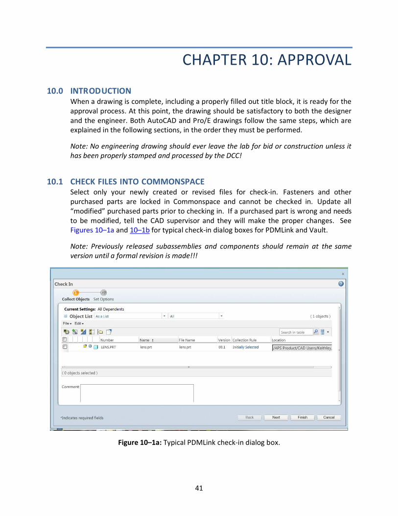
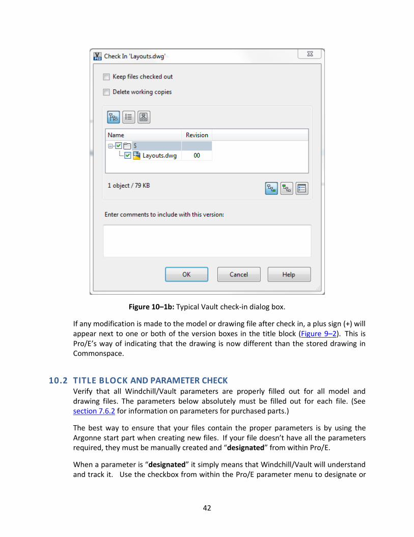
10.1 CHECK FILES INTO COMMONSPACE Select only your newly created or revised files for check-in. Fasteners and other
purchased parts are locked in Commonspace and cannot be checked in. Update all
“modified” purchased parts prior to checking in. If a purchased part is wrong and needs
to be modified, tell the CAD supervisor and they will make the proper changes. See
Figures 10–1a and 10–1b for typical check-in dialog boxes for PDMLink and Vault.
Note: Previously released subassemblies and components should remain at the same
version until a formal revision is made!!!
Figure 10–1a: Typical PDMLink check-in dialog box.
42
Figure 10–1b: Typical Vault check-in dialog box.
If any modification is made to the model or drawing file after check in, a plus sign (+) will
appear next to one or both of the version boxes in the title block (Figure 9–2). This is
Pro/E’s way of indicating that the drawing is now different than the stored drawing in
Commonspace.
10.2 TITLE BLOCK AND PARAMETER CHECK Verify that all Windchill/Vault parameters are properly filled out for all model and
drawing files. The parameters below absolutely must be filled out for each file. (See
section 7.6.2 for information on parameters for purchased parts.)
The best way to ensure that your files contain the proper parameters is by using the
Argonne start part when creating new files. If your file doesn’t have all the parameters
required, they must be manually created and “designated” from within Pro/E.
When a parameter is “designated” it simply means that Windchill/Vault will understand
and track it. Use the checkbox from within the Pro/E parameter menu to designate or
43
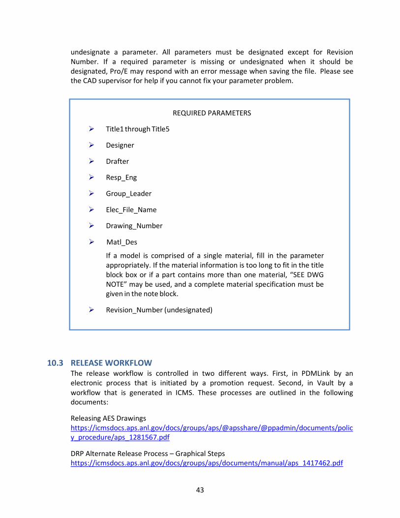
undesignate a parameter. All parameters must be designated except for Revision
Number. If a required parameter is missing or undesignated when it should be
designated, Pro/E may respond with an error message when saving the file. Please see
the CAD supervisor for help if you cannot fix your parameter problem.
REQUIRED PARAMETERS
� Title1 through Title5
� Designer
� Drafter
� Resp_Eng
� Group_Leader
� Elec_File_Name
� Drawing_Number
� Matl_Des
If a model is comprised of a single material, fill in the parameter
appropriately. If the material information is too long to fit in the title
block box or if a part contains more than one material, “SEE DWG
NOTE” may be used, and a complete material specification must be
given in the note block.
� Revision_Number (undesignated)
10.3 RELEASE WORKFLOW The release workflow is controlled in two different ways. First, in PDMLink by an
electronic process that is initiated by a promotion request. Second, in Vault by a
workflow that is generated in ICMS. These processes are outlined in the following
documents:
Releasing AES Drawings
https://icmsdocs.aps.anl.gov/docs/groups/aps/@apsshare/@ppadmin/documents/polic
y_procedure/aps_1281567.pdf
DRP Alternate Release Process – Graphical Steps
https://icmsdocs.aps.anl.gov/docs/groups/aps/documents/manual/aps_1417462.pdf

44
Design and Drafting Group Engineering Document Management Plan
https://icmsdocs.aps.anl.gov/docs/groups/aps/@apsshare/@ppadmin/documents/polic
y_procedure/aps_1438268~1.pdf
45
CHAPTER 11: PRINTING AND STORAGE
11.0 INTRODUCTION This section describes the process of plotting drawings from both AutoCAD and Pro/E
and explains some of the configuration requirements. There are numerous printers,
plotters, and copiers from which drawings can be printed at the APS, but the focus in
this chapter will be on those that are in the Design and Drafting area.
Note: It is not the responsibility of drafters or designers to supply copies of drawings to
engineers, technicians, etc. If they choose to do so, it is merely a courtesy. All drawing
requests should be directed to the Document Control Center.
11.1 PRINTERS, PLOTTERS, AND COPIERS Listed below are the printers and plotters available to designers and their capabilities.
Small Format:
Zero1 (laser printer) b&w A, B
Zero2 (laser printer) b&w A, B
Zero4 (laser copier) b&w A, B
Large Format:
Acad3 (plotter) color C and D*
Acad6 (plotter) color D, E and J’*
Acad10 (plotter) b&w C, D, E
*Although the larger format plotters can handle smaller paper sizes, they will waste
paper in doing so. It is recommended that the printers be used for smaller paper sizes.
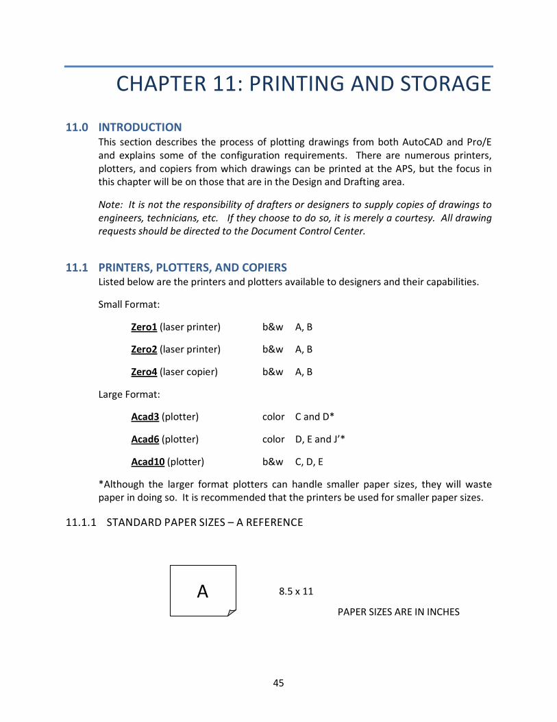
11.1.1 STANDARD PAPER SIZES – A REFERENCE
A 8.5 x 11
PAPER SIZES ARE IN INCHES
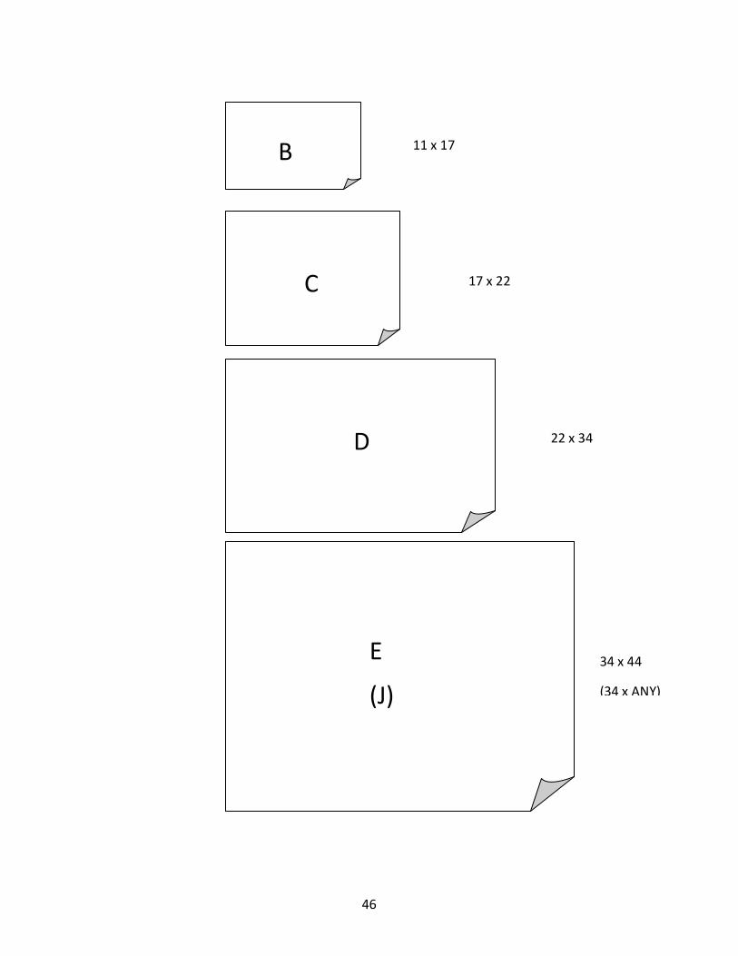
46
B
C
E
(J)
11 x 17
34 x 44
(34 x ANY)
17 x 22
D 22 x 34
47
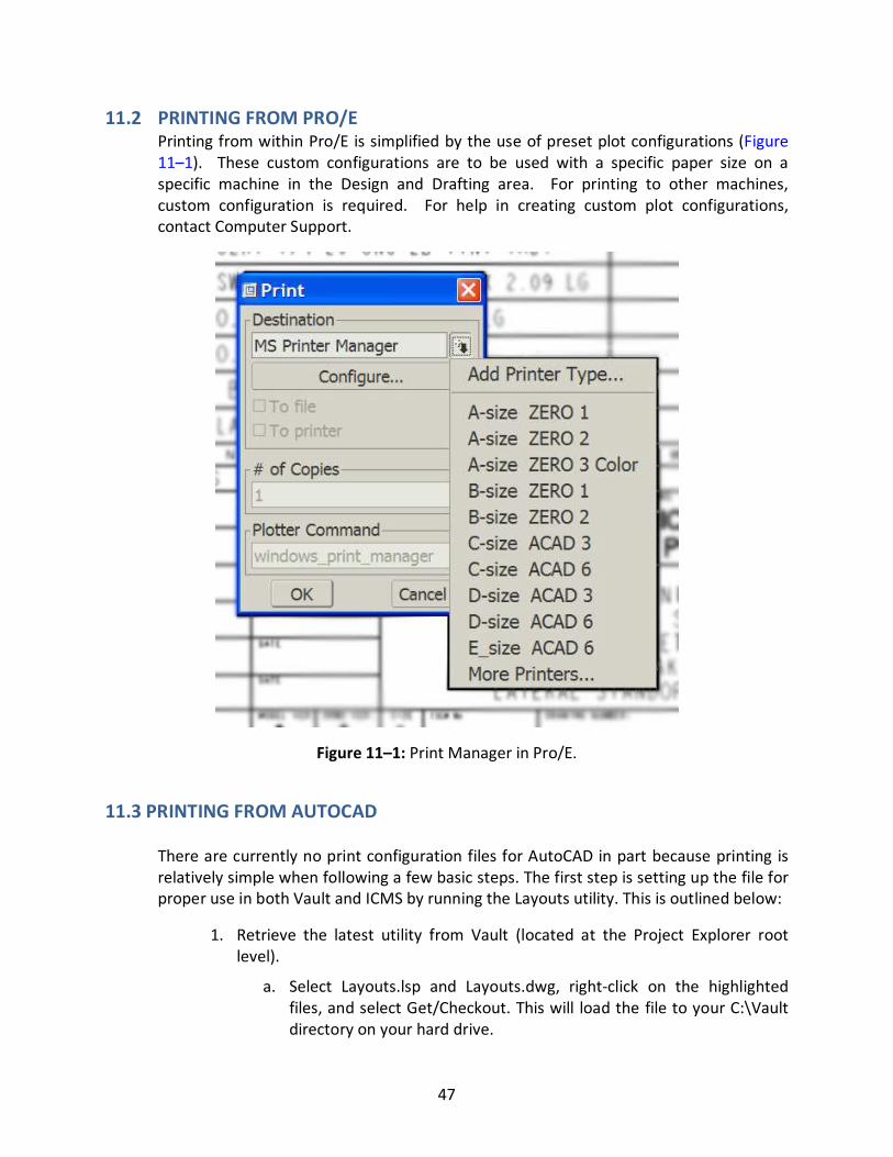
11.2 PRINTING FROM PRO/E Printing from within Pro/E is simplified by the use of preset plot configurations (Figure
11–1). These custom configurations are to be used with a specific paper size on a
specific machine in the Design and Drafting area. For printing to other machines,
custom configuration is required. For help in creating custom plot configurations,
contact Computer Support.
Figure 11–1: Print Manager in Pro/E.
11.3 PRINTING FROM AUTOCAD
There are currently no print configuration files for AutoCAD in part because printing is
relatively simple when following a few basic steps. The first step is setting up the file for
proper use in both Vault and ICMS by running the Layouts utility. This is outlined below:
1. Retrieve the latest utility from Vault (located at the Project Explorer root
level).
a. Select Layouts.lsp and Layouts.dwg, right-click on the highlighted
files, and select Get/Checkout. This will load the file to your C:\Vault
directory on your hard drive.
48
2. In your drawing file type “Appload” and load the Layouts routine from your
C:\Vault directory.
3. Run Layouts by typing “layouts” at the command prompt.
4. Follow the instructions to complete the process.
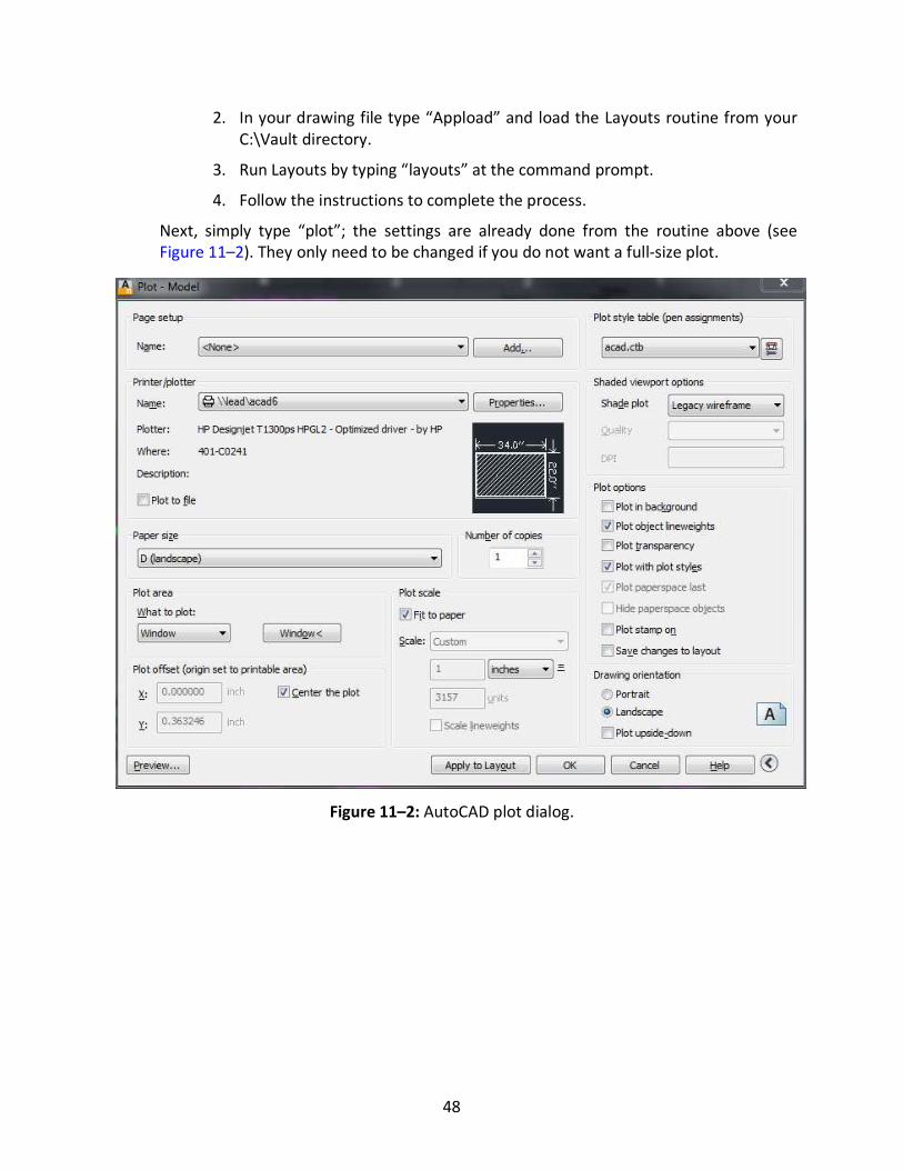
Next, simply type “plot”; the settings are already done from the routine above (see
Figure 11–2). They only need to be changed if you do not want a full-size plot.
Figure 11–2: AutoCAD plot dialog.
49
CHAPTER 12: FACILITIES DESIGN
STANDARDS
12.0 INTRODUCTION This document defines the standards to be followed by architectural engineering (A/E)
firms and design build (D/B) firms doing work for the APS project. This will assure
compatibility between the above-mentioned firms and the APS engineers, designers,
and drafters, and will provide drawings and designs of professional quality at minimum
cost to the project.
12.1 GENERA L Consistent with the objective of this standard is the need to discuss with and achieve
agreement with the above-mentioned firms regarding the particular drafting methods
employed.
Because of the broad scope of APS design and drafting activities and the need for
universally uniform interpretation of such work, avoid local and special drafting
practices. Argonne standards and practices are intended to be compatible with those of
industry and governmental agencies; therefore, the following general standards are
presented.
Deviation from these criteria proposed by A/E or D/B firms shall be discussed with the
Laboratory’s Project or CAD Manager prior to implementation. If it is concluded that
such deviations will benefit the work and will not jeopardize the compatibility of the
electronic files or the reliability of the resulting construction, the specific deviations will
be permitted. No such deviations will serve as a blanket revision of these standards.
12.1.1 FLOOR PLAN ORIENTATION
Floor plans are to be oriented with north arrow pointing either up or to the right, never
down or to the left.
12.1.2 DRAWING SCALES
� Plans
• All floor plans for construction drawings will be drawn at a scale of 1/4” per
ft. If this is not feasible, downsizing is permitted to 1/8” or 1/16” upon
approval of the Project Manager.
• Increasing size of floor plans is permissible by a factor of 1/8” per ft. (e.g.,
3/8”, 1/2”).

50
• Group is bubbled, with the enlargement factor noted.
� Elevations
• Building elevations, interior elevations, and building cross sections shall be
drawn at a minimum of 1/4” per ft.
• Increasing or decreasing the size of building elevations, interior elevations,
and building cross sections is acceptable at a rate scale of 1/8” per ft. (e.g.,
3/8”, 1/2”, 1/4”, 1/8”).
� Details and Sections
• Details and sections shall be drawn to scale utilizing either 1/2” = 1’-0”, 1” =
1’-0”, 1-1/2” = 1’, 3” = 1’-0”. If details or sections are not drawn to scale,
deviations will be noted, i.e., SCALE: N.T.S.
12.1.3 DRAWING SCALE PROVISIONS/NOMENCLATURE
All electronic drawing files will be drawn to limits, i.e., scale; no electronic files will be
accepted when drawings are plotted at a different scale than what is shown on the
drawing. All drawings will have graphic scales and conventional architectural and
engineering scales. For example:
Building (Architectural/Engineering) Site (Civil/Landscaping)
1/16” = 1’-0” 1” = 10’
3/16” = 1’-0” 1” = 20’
3/8” = 1’-0” 1” = 30’
1/8” = 1’-0” 1” = 40’
1/4” = 1’-0” 1” = 50’
3/8” = 1’-0” 1” = 60’
1/2” = 1’-0” 1” = 100’
3/4” = 1’-0” 1” = 200’
1” = 1’-0” 1” = 300’
1-1/2” = 1’-0” 1” = 400’
3” = 1’-0” 1” = 500’
6” = 1’-0” 1” = 600’
51
Any deviations must be approved prior to usage by the APS Project Manager or the APS
CAD Manager.
12.1.4 DRAWING REDUCTION
If drawings are reduced from their original size for publication, etc., the following note
must appear on the drawing: Warning – This Drawing Has Been Reduced.
12.1.5 DIMENSIONING
All dimensions shown on the drawings will be true dimensions of the graphic
representation shown on the drawing. If not, dimensions will be accompanied by the
following abbreviation: N.T.S. located to the right or below the given dimensions. For
example:
4’-0”
|← -------------------- →|
(N.T.S.)
12.1.6 PLOTTING
A plotting schedule will be provided on each drawing defining screen colors and pen
weights used to create the drawing.
12.1.7 MANUAL DRAWN DETAILS, SECTIONS, ELEVATIONS, FLOOR PLANS, ETC.
Manual drawn details, sections, elevations, etc. shall be avoided and will not be
accepted. If this system is utilized for whatever reason, the A/E and D/B firms, at their
own expense, will provide an electronically scanned file of these drawings, suitable for
use in AutoCAD. Mixtures of CAD files with manual methods of drawing, i.e., line work
plus cut and paste, will not be accepted.
All drawings shall include both a standard scale and a graphic scale.
12.1.8 DRAWING SHEETS
1. Material
• Final original drawings shall be presented as a hard copy vellum drawing and
as electronically generated CAD files plotted on a plotter.
2. Size
• All full-size drawings shall be size E. Standard sheet sizes are shown in section
11.1.1. All drawing sets/packages shall be of one size only.
52
• All plotted drawings should have margin notes showing, as a minimum, the
project or building designation, CADD file name, scale, drawing number, date
of last revision to the drawing, plot date, and time.
12.1.9 TEXT
Standard text fonts will be used. These are as provided in AutoCAD Desktop. Deviations
in font styles will be submitted for approval prior to usage. All notes, headings, legends,
etc. will be placed on default layers as prescribed in AutoCAD/2013 Desktop. Deviations
will be accepted if placed on a layer call “text”. Any further deviations will be submitted
for approval prior to usage.
Insofar as all drawings are drawn to scale, i.e., limits, text must also be drawn to the
appropriate scale.
12.1.10 CAD COMPATIBILITY
All A/E firms shall provide Argonne with electronic drawing data compatible with the
APS/2002 Desktop in-house CAD system. The following is a list of CAD computer
programs being used by the APS project at this time:
AutoCAD-Version 2013
Autodesk-Architectural Desktop 2013
Autodesk – Structural
Autodesk Building – Electrical 1 Autodesk Building – Mechanical 1
1. H.V.A.C.
2. Piping
3. Plumbing
Autodesk – Autoplant Design (ACAD 2013) Autodesk – P&ID V.15.10
Autoplant 2D and 3D
Electrical – Mechanical Combined Launch
12.1.11 SYMBOLS
Symbols shall be as per the standard symbols in the latest versions of AutoCAD. Should
nonstandard symbols be required, prior written approval shall be obtained from the APS
Project Manager.
See section 12.1.10 for specific programs, e.g., AutoCAD 2013, Autodesk.
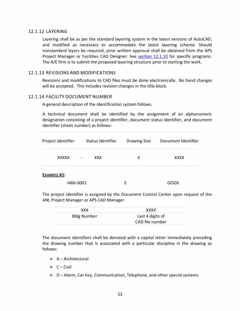
53
12.1.12 LAYERING
Layering shall be as per the standard layering system in the latest versions of AutoCAD,
and modified as necessary to accommodate the latest layering scheme. Should
nonstandard layers be required, prior written approval shall be obtained from the APS
Project Manager or Facilities CAD Designer. See section 12.1.10 for specific programs.
The A/E firm is to submit the proposed layering structure prior to starting the work.
12.1.13 REVISIONS AND MODIFICATIONS
Revisions and modifications to CAD files must be done electronically. No hand changes
will be accepted. This includes revision changes in the title block.
12.1.14 FACILITY DOCUMENT NUMBER
A general description of the identification system follows.
A technical document shall be identified by the assignment of an alphanumeric
designation consisting of a project identifier, document status identifier, and document
identifier (sheet number) as follows:
Project Identifier Status Identifier Drawing Size Document Identifier
XXXXX - XXX X XXXX
EXAMPLE #1:
J466-0001 E GOOX
The project identifier is assigned by the Document Control Center upon request of the
ANL Project Manager or APS CAD Manager.
XXX XXXX
Bldg Number Last 4 digits of
CAD file number
The document identifiers shall be denoted with a capital letter immediately preceding
the drawing number that is associated with a particular discipline in the drawing as
follows:
� A – Architectural
� C – Civil
� D – Alarm, Car Key, Communication, Telephone, and other special systems
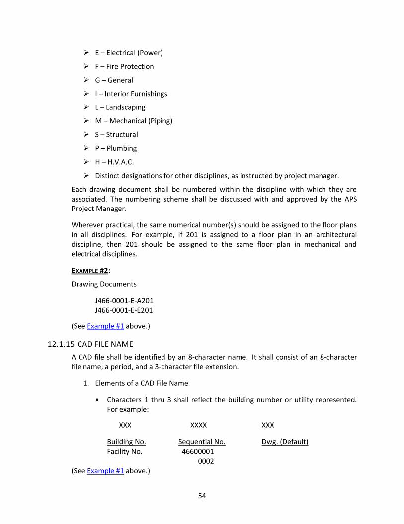
54
� E – Electrical (Power)
� F – Fire Protection
� G – General
� I – Interior Furnishings
� L – Landscaping
� M – Mechanical (Piping)
� S – Structural
� P – Plumbing
� H – H.V.A.C.
� Distinct designations for other disciplines, as instructed by project manager.
Each drawing document shall be numbered within the discipline with which they are
associated. The numbering scheme shall be discussed with and approved by the APS
Project Manager.
Wherever practical, the same numerical number(s) should be assigned to the floor plans
in all disciplines. For example, if 201 is assigned to a floor plan in an architectural
discipline, then 201 should be assigned to the same floor plan in mechanical and
electrical disciplines.
EXAMPLE #2:
Drawing Documents
J466-0001-E-A201
J466-0001-E-E201
(See Example #1 above.)
12.1.15 CAD FILE NAME
A CAD file shall be identified by an 8-character name. It shall consist of an 8-character
file name, a period, and a 3-character file extension.
1. Elements of a CAD File Name
• Characters 1 thru 3 shall reflect the building number or utility represented.
For example:
XXX XXXX XXX
Building No. Sequential No. Dwg. (Default)
Facility No. 46600001
0002
(See Example #1 above.)
55
2. Additional Information
• The following information shall also be provided along with the electronic
files.1
a. Drawings list
b. Line types, symbols, etc.
c. Electronic file name and drawing “J” number and title
d. Listing of all text fonts and styles used other than the stock font files
offered in AutoCAD.
• The 5-digit code shall be a unique number sequentially assigned throughout
the project, and each sheet will be uniquely numbered.
3. File Extension
• The 3-character file extension shall always be DWG for AutoCAD files.
4. Examples:
46600001.DWG
46600002.DWG
46600010.DWG
12.1.16 SECTIONS AND DETAILING NOMENCLATURE
The letters for sections will be in sequential order beginning with the letters A through Z.
If more letters are required, a double-lettering system will be employed, such as AA, BB,
etc.
The numbers for details will be in sequential order beginning with 1.
12.1.17 TITLE BLOCK
The title block should be an attribute. A title block for each project shall be provided to
the A/E and D/B firms for their use in AutoCAD drawings and to serve as an attribute
that is compatible with APS uplinks.
12.1.18 ELECTRONIC DRAWING REVIEW
Electronic drawing files will be submitted for review at various stages of the project;
typically interim files shall be submitted at approximately 2-week intervals for review by
the CAD designer to insure adherence to the general drafting standards as specified.
1 Specify which drawings are electronic scans of manual drawings and which are CAD files.

56
The electronic files will be reviewed for the standards listed and the following generally
accepted CAD practices.
� Fragmented lines
� Unnecessary improper layering as described
� Improper text size and fonts
� Scale
� Dimensioning scale
� Unnecessary electronic files
� Pieces or blocks outside the electronic border
� Multiple blocks, lines, text inserted on top of each other, etc.
12.1.19 FINAL SUBMITTAL OF DRAWINGS
Drawings shall be presented on vellum as stated in section 12.1.8, and on CD. As
technology proceeds, other electronic media may be used contingent on project
manager or CAD designer approval.
57
CHAPTER 13: SAFETY INTERLOCK SYSTEMS
13.0 INTRODUCTION The Safety Interlocks (SI) Group is responsible for the following beamline and front-end
interlock safety systems:
FEEPS - Front-End Equipment Protection System
PSS - Personal Safety System
BLEPS - BeamLine Equipment Protection System
Drawings for these systems must follow strict standards that include a numbering
convention. The Access Control Interlock System (ACIS) is separate and uses a different
system.
13.1 GENERAL STANDARDS FOR BEAMLINE AND FRONT-END INTERLOCKS
DRAWINGS
13.1.1 DRAWING STANDARDS
Electrical drawings should follow the drawing symbols described in the IEEE Standard
315 and 315A, American National Standard Canadian Standard, Graphic Symbols for
Electrical and Electronics Design.
13.1.2 PURCHASED PARTS
Commercially available components are to be used whenever possible. All information
required for purchasing the components should be furnished in the drawing package.
13.1.3 DETAIL DRAWINGS
Drawings should be made on a D-size title block.
E-size title blocks may be used for large schematics and circuit board detail drawings.
Multiple cables and required parts may be detailed on a drawing.
13.1.4 TEXT SIZE
Text height should be 0.08 or 0.1 for standard text and 0.13 for topic descriptors.
Text size may be as small as 0.06 on circuit board detail drawings and some schematics.
13.1.5 TEXT COLOR
Text color should be black/white when not specified by the SI Group.
58
Text color on circuit board schematics should be as follows: red for wire information,
blue for hardware information.
13.2 DRAWING NUMBER KEY FOR BEAMLINE AND FRONT-END INTERLOCKS
DRAWINGS
13.2.1 ALL DRAWINGS WILL HAVE A WBS AND AN LDN NUMBER.
WBS No. = 4104_ _ _ _
(WBS number is locked in at DCC)
If not beamline-specific, stop at 4104 plus 2-digit sector number
If beamline-specific, add 3rd and 4th digits: 01=BM, 02=ID
LDN# = _ _ _ _ _ _ – 6-digit number = drawing description
1st
& 2ND
# (system)
00-09 = not used
10-19 = FEEPS (11=ver 1, 12= ver 2 & 2.1, 13=ver 3)
20-29 = PSS (20=gen 1, 21=gen 3)
30-39=BLEPS
40-89=Future use
90-99=Procedures – the 3rd and 4th numbers need to be set up by the doc. users
3rd
& 4th
# (location)-not used for 90-99 (procedures)
00= not station specific – exp. floor
01= 1st station
02= 2nd station
03= 3rd station, etc.
20= Mezzanine
21 & 22= Related equipment – mechanical assemblies (locks, panel blanks, etc.)
97= Test cart/boxes
98= Prototype

59
99= Simulator
5th & 6th # (item)
Sequential to a pattern
Example:
41042402-202018 =
Beamline and front-end interlock 24 ID – PSS Gen 1, mezzanine, sequential
60
CHAPTER 14: REFERENCES
14.0 REFERENCES 1 ASME Y14.5 and ASME Y14.100, Dimensioning, Tolerancing, and Engineering
Drawing Practices Package
2 ASME Y14.38-2007 (R2013), Abbreviations and Acronyms for Use on Drawings
and Related Documents
3 Modern Drafting Practices and Standards Manual, Update 77, Genium Publishing
Corporation
4 Vendor.sym located at “\\lead\ptc\Pro_structure\Pro_std\Symbol_dir”


![Triton Drafting Standards Manual[1]](https://img.pdfslide.us/doc/110x75/543ba14bafaf9f4a578b4a06/triton-drafting-standards-manual1.jpg)