Embed Size (px)
Citation preview

DDRRAAFFTTIINNGG SSTTAANNDDAARRDDSS FFOORR
WWAATTEERR//WWAASSTTEEWWAATTEERR
PPIIPPEELLIINNEE PPRROOJJEECCTTSS
OOccttoobbeerr,, 22001111
DWU PIPELINE DRAFTING STANDARDS TOC-1 OCTOBER 2011
TABLE OF CONTENTS
PREFACE P.1 BACKGROUND.........................................................................................................P-1
P.2 ABBREVIATIONS .....................................................................................................P-2
CHAPTER 1 GENERAL REQUIREMENTS
1.1 INTRODUCTION ......................................................................................................1-1
1.2 SOFTWARE APPLICATION ......................................................................................1-1
1.3 DATA COLLECTION AND DRAWING CHECKLIST...................................................1-1
1.4 FILE MANAGEMENT ...............................................................................................1-2
CHAPTER 2 DRAFTING CONVENTIONS
2.1 GENERAL... .. ..........................................................................................................2-1
2.2 DRAFTING BASE POINTS ........................................................................................2-1
2.3 MASTER MODEL SHEET MODEL ...........................................................................2-1
2.4 REFERENCES……...................................................................................................2-1
2.5 TEXT FONT AND ORIENTATIONS............................................................................2-2
2.6 ANNOTATIONS…… ................................................................................................2-3
2.7 EXISTING, PROPOSED AND FUTURE FEATURES…….............................................2-3
2.8 DRAWING ORIENTATION........................................................................................2-4
2.9 STATIONS……... .....................................................................................................2-4
2.10 COORDINATES……... .............................................................................................2-5
2.11 CROSS AND PARALLEL UNDERGROUND UTILITIES…………...............................2-5
2.12 SLOPE………..........................................................................................................2-6
2.13 ELEVATIONS……... ................................................................................................2-6
2.14 FLOWLINES/INVERT ELEVATIONS……... ..............................................................2-6
2.15 DRAWING SCALES ..................................................................................................2-7
2.16 MATCH MARKS ......................................................................................................2-7
DWU PIPELINE DRAFTING STANDARDS TOC-2 OCTOBER 2011
CHAPTER 3 DRAWING CONFIGURATION
3.1 GENERAL…. ...........................................................................................................3-1
3.2 PLAN AND PROFILE CONFIGURATION ...................................................................3-1
3.3 COVER SHEET.........................................................................................................3-2
3.4 GENERAL NOTES….. ..............................................................................................3-4
3.5 STANDARD DESIGN SHEET………………..……. ..................................................3-4
3.6 STANDARD CALLOUTS …………….......................................................................3-11
CHAPTER 4 WORKING UNITS, COLOR, STYLE AND WEIGHT
4.1 GENERAL…. ...........................................................................................................4-1
4.2 WORKING UNITS ....................................................................................................4-1
4.3 GLOBAL ORIGIN.....................................................................................................4-2
4.4 COLOR…………………. .......................................................................................4-2
4.5 LINE STYLE………………………….....................................................................4-2
4.6 LINE WEIGHT……. ................................................................................................4-3
CHAPTER 5 LEVEL MANAGEMENT
5.1 GENERAL…. ...........................................................................................................5-1
5.2 LEVEL NAMING CONVENTION ...............................................................................5-1
5.3 STANDARD LEVEL CATEGORIES……....................................................................5-2
5.4 PREDEFINED LEVELS..............................................................................................5-2
DWU PIPELINE DRAFTING STANDARDS TOC-3 OCTOBER 2011
CHAPTER 6 DRAFTING RESOURCE LIBRARIES
6.1 GENERAL ................................................................................................................6-1
6.2 PREDEFINED FILES .................................................................................................6-1
6.3 SEED FILE ...............................................................................................................6-2
6.4 LEVEL LIBRARY .....................................................................................................6-2
6.5 CELL LIBRARY .......................................................................................................6-2
6.6 TEXT STYLE RESOURCE LIBRARY.........................................................................6-2
6.7 MISCELLANEOUS DRAWING FEATURES ................................................................6-3
6.8 REFERENCE SCHEMATICS......................................................................................6-3
CHAPTER 7 PLOT CONFIGURATION
6.1 GENERAL ................................................................................................................7-1
6.2 ATTRIBUTE DEFINITIONS.......................................................................................7-1
DWU PIPELINE DRAFTING STANDARDS TOC-4 OCTOBER 2011
LIST OF TABLES
TABLE 1.4.1 FILE NAMING CONVENTION
TABLE 3.6.1 WATER/WASTEWATER TITLE CALLOUTS
TABLE 3.6.2 TYPICAL WATER MAIN CALLOUTS
TABLE 3.6.3 TYPICAL WASTEWATER MAIN CALLOUTS
TABLE 4.2 WORKING UNITS
TABLE 4.4 LIST OF COLORS
TABLE 4.5 LIST OF LINE STYLES
TABLE 4.2 LIST OF LINE WEIGHTS
TABLE 5.3 LIST OF STANDARD LEVELS CATEGORIES
TABLE 5.4 LIST OF PREDEFINED LEVELS
TABLE 6.2: LIST OF PREDEFINED FILES
DWU PIPELINE DRAFTING STANDARDS TOC-5 OCTOBER 2011
LIST OF FIGURES
FIGURE 1.4.2 SEQUENCE OF FILING
FIGURE 2.5 TEXT AND FONT ORIENTATION CONVENTIONS
FIGURE 2.8 DRAWING ORIENTATION CONVENTIONS
FIGURE 2.8 DRAWING ORIENTATION CONVENTIONS
FIGURE 2.10 STATIONING CONVENTION AND CROSS-REFERENCING
FIGURE 2.14 FLOWLINE CONFIGURATIONS AT WASTEWATER MANHOLE
FIGURE 2.16.1 TYPICAL MATCH MARKS FOR A SINGLE UTILITY PROJECT
FIGURE 2.16.2 TYPICAL MATCH MARKS FOR A COMBINED UTILITY PROJECT
FIGURE 2.16.1 TYPICAL MATCH MARKS FOR A VERTICAL SHIFT
FIGURE 3.3.1 TYPICAL COVER SHEET A MAJOR UTILITY PROJECT
FIGURE 3.3.2 TYPICAL COVER SHEET A MULTIPLE LOCATIONS PROJECT
FIGURE 3.4 TYPICAL GENERAL NOTE SHEET
FIGURE 3.5 STANDARD DESIGN SHEET
FIGURE 3.5.1 STANDARD DESIGN SHEET BORDER
FIGURE 3.5.2 STANDARD TITLE BLOCK
FIGURE 3.5.5.1 P.E. DISCLAIMER FOR PRELIMINARY PLANS
FIGURE 3.5.5.3 DISCLAIMER FOR RECORD DRAWING
FIGURE 4.4 STANDARD COLOR, STYLE AND WEIGHT DESIGNATIONS
FIGURE 6.4A: CELL LIBRARY- GENERAL
FIGURE 6.4B: CELL LIBRARY- WATER AND WASTEWATER
DWU PIPELINE DRAFTING STANDARDS TOC-7 OCTOBER 2011
LIST OF EXHIBITS
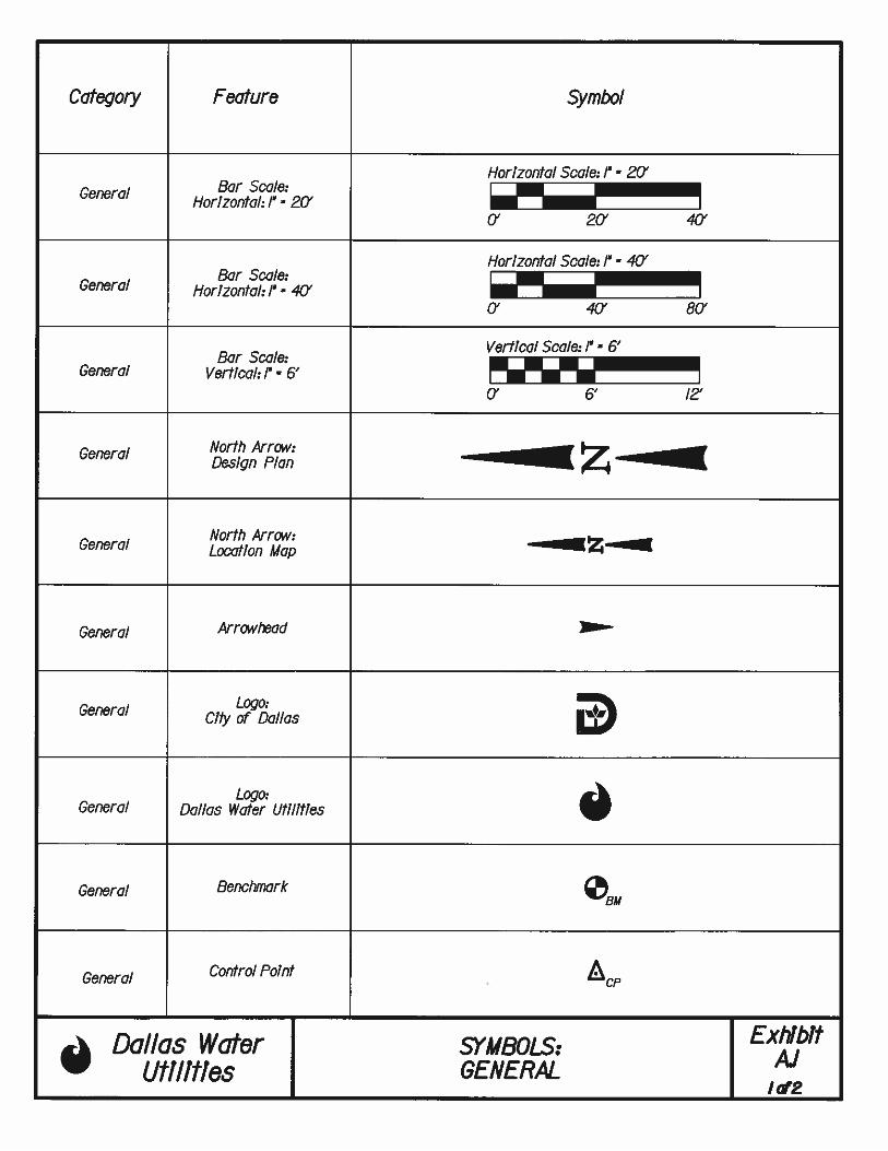
EXHIBIT A.1 SYMBOLS: GENERAL
EXHIBIT A.2 SYMBOLS: TOPOGRAPHIC FEATURES
EXHIBIT A.3 SYMBOLS: PAVING
EXHIBIT A.4 SYMBOLS: STORM DRAINS
EXHIBIT A.5 SYMBOLS: UTILITIES
EXHIBIT A.6 SYMBOLS: WATER APPURTENANCES
EXHIBIT B.1 NORTH ARROW, ARROWHEAD, DIMENSIONS AND LEADER LINES
EXHIBIT C.1 TEXT STYLE: STANDARD TITLE BLOCK
EXHIBIT C.2 TEXT STYLE: STANDARD DESIGN SHEET MISC. ITEMS
EXHIBIT C.3 TEXT STYLE: GENERAL PLAN VIEW
EXHIBIT C.4 TEXT STYLE: PROPERTY PLAN VIEW
EXHIBIT C.5 TEXT STYLE: WATER/WASTEWATER PLAN VIEW
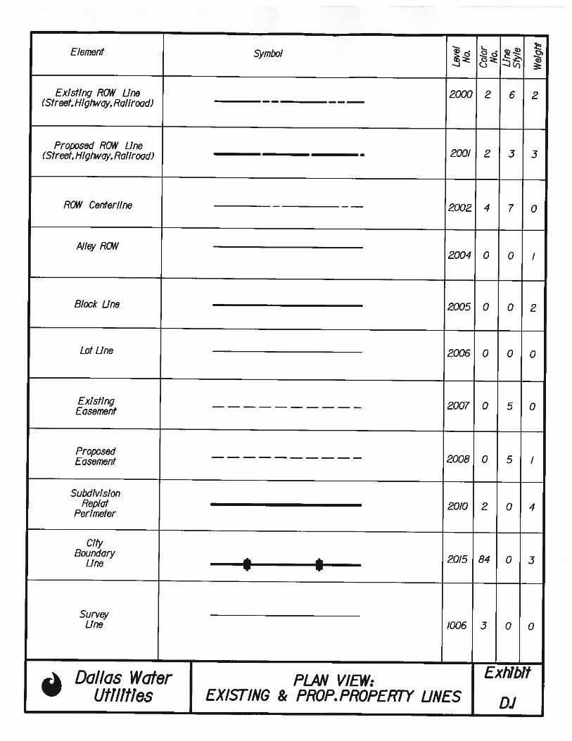
EXHIBIT D.1 PLAN VIEW: EXISTING & PROP. PROPERTY LINES
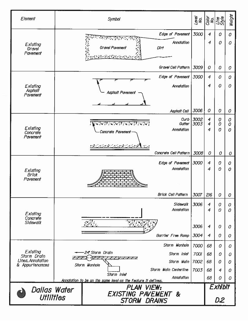
EXHIBIT D.2 PLAN VIEW: EXISTING PAVEMENT & STORM DRAINS
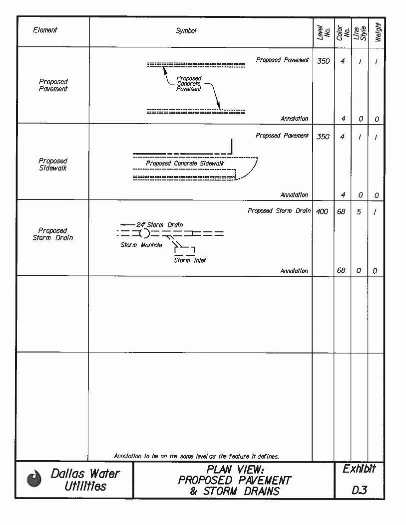
EXHIBIT D.3 PLAN VIEW: PROPOSED PAVEMENT & STORM DRAINS
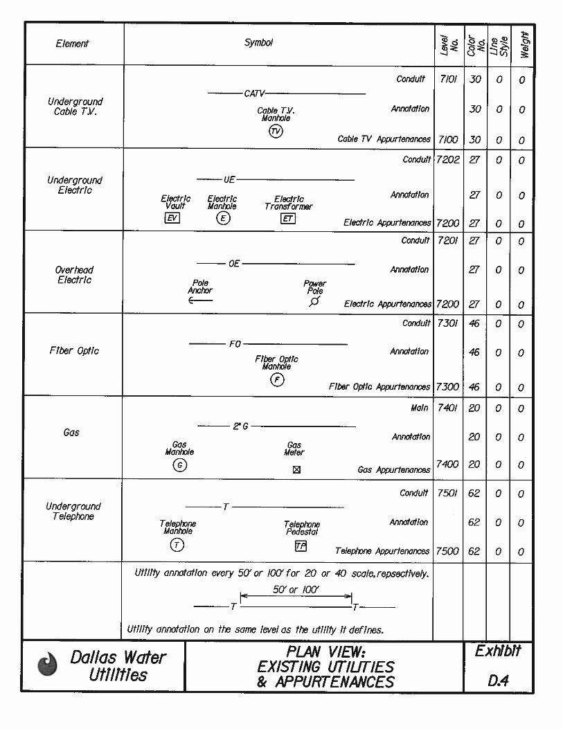
EXHIBIT D.4 PLAN VIEW: EXISTING UTILITIES & APPURTENANCES
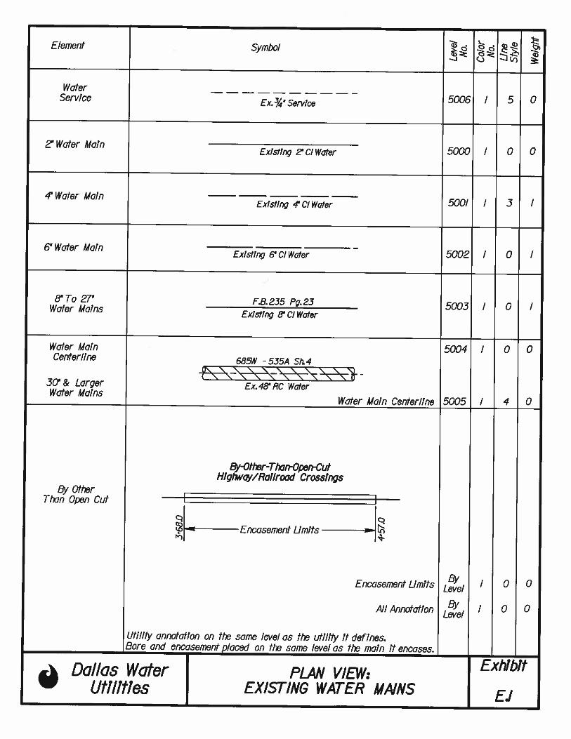
EXHIBIT E.1 PLAN VIEW: EXISTING WATER MAINS
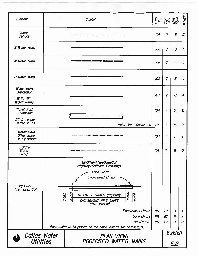
EXHIBIT E.2 PLAN VIEW: PROPOSED WATER MAINS
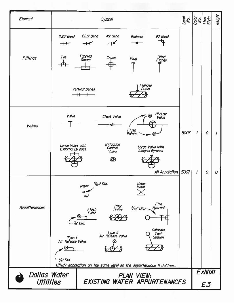
EXHIBIT E.3 PLAN VIEW: EXISTING WATER APPURTENANCES
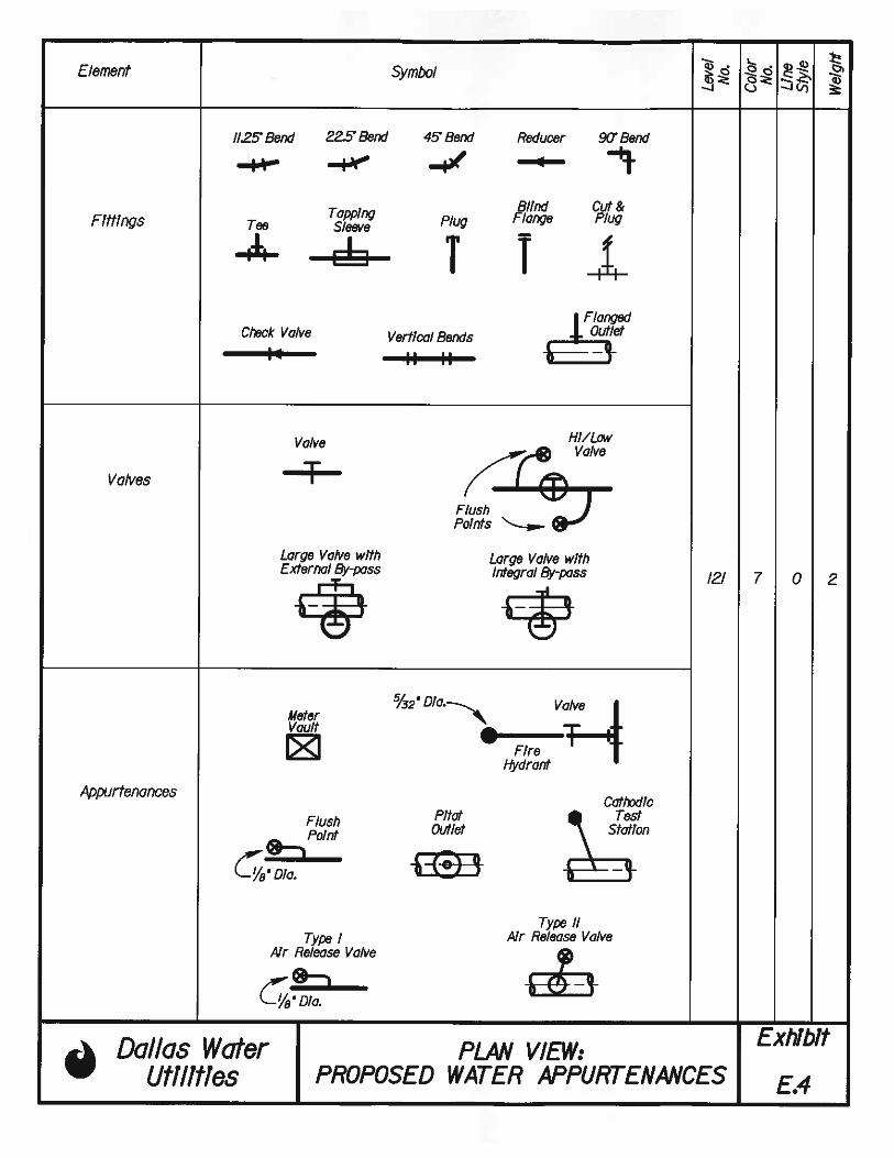
EXHIBIT E.4 PLAN VIEW: PROPOSED WATER APPURTENANCES
EXHIBIT F.1 PLAN VIEW: EXISTING WASTEWATER MAINS
EXHIBIT F.2 PLAN VIEW: PROPOSED WASTEWATER MAINS
EXHIBIT F.3 PLAN VIEW: EXISTING WASTEWATER APPURTENANCES
EXHIBIT F.4 PLAN VIEW: PROPOSED WASTEWATER APPURTENANCES
DWU PIPELINE DRAFTING STANDARDS TOC-7 OCTOBER 2011
EXHIBIT G.1 TEXT STYLE: GENERAL PROFILE VIEW
EXHIBIT G.2 TEXT STYLE: EXISTING/PROP. WATER/WASTEWATER PROFILE VIEW
EXHIBIT H.1 PROFILE VIEW: EXISTING UTILITIES AND APPURTENANCES
EXHIBIT H.2 PROFILE VIEW: PROPOSED UTILITIES AND APPURTENANCES
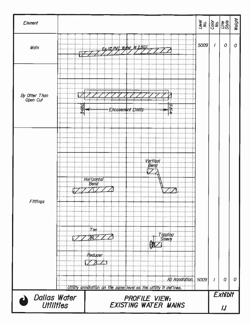
EXHIBIT I.1 PROFILE VIEW: EXISTING WATER MAINS
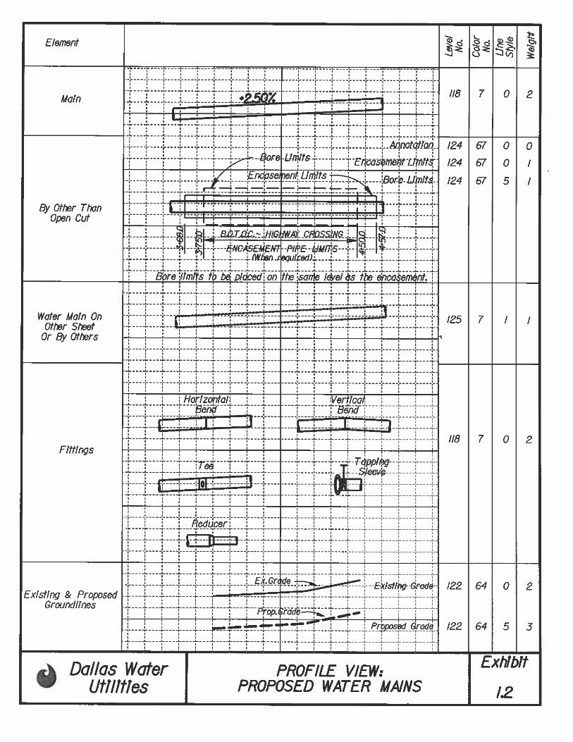
EXHIBIT I.2 PROFILE VIEW: PROPOSED WATER MAINS
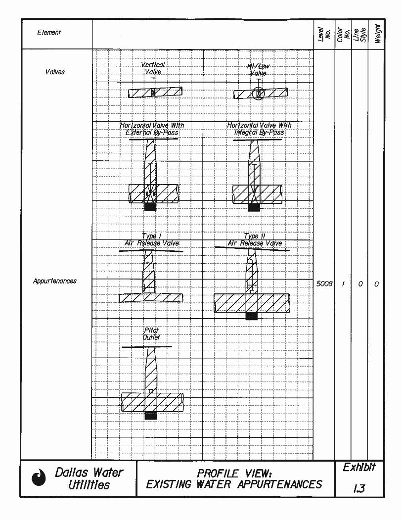
EXHIBIT I.3 PROFILE VIEW: EXISTING WATER APPURTENANCES
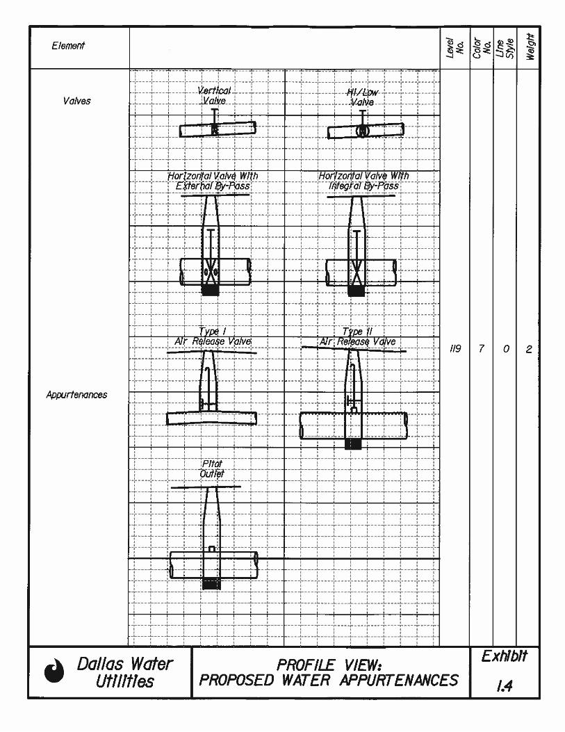
EXHIBIT I.4 PROFILE VIEW: PROPOSED WATER APPURTENANCES
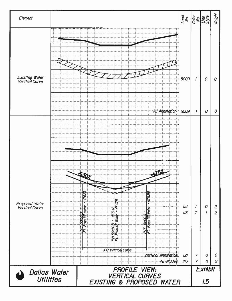
EXHIBIT I.5 PROFILE VIEW: VERTICAL CURVES EXISTING AND PROPOSED WATER
MAINS
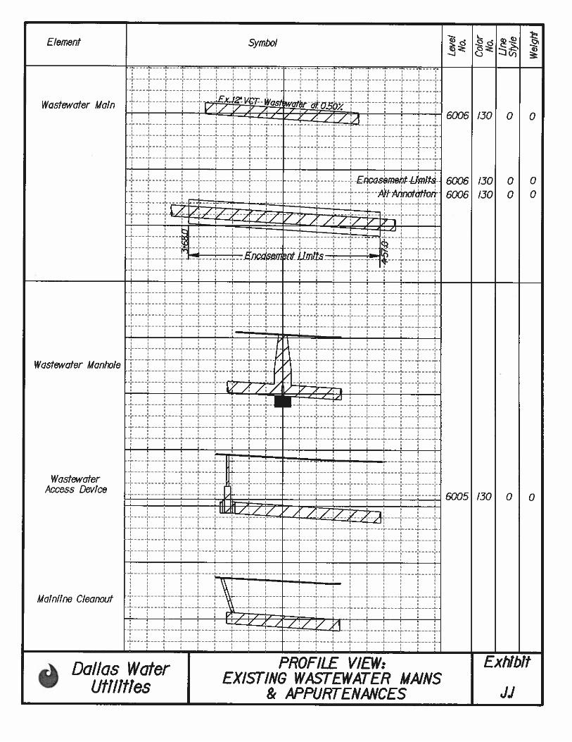
EXHIBIT J.1 PROFILE VIEW: EXISTING WASTEWATER MAINS AND APPURTENANCES
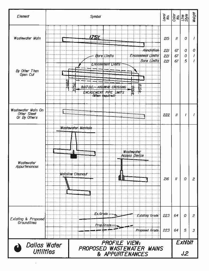
EXHIBIT J.2 PROFILE VIEW: PROPOSED WASTEWATER MAINS AND APPURTENANCES
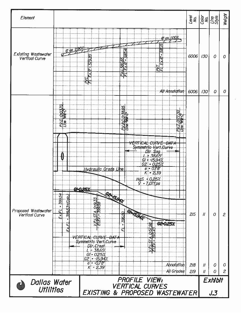
EXHIBIT J.3 PROFILE VIEW: VERTICAL CURVES EXISTING AND PROPOSED
WASTEWATER MAINS
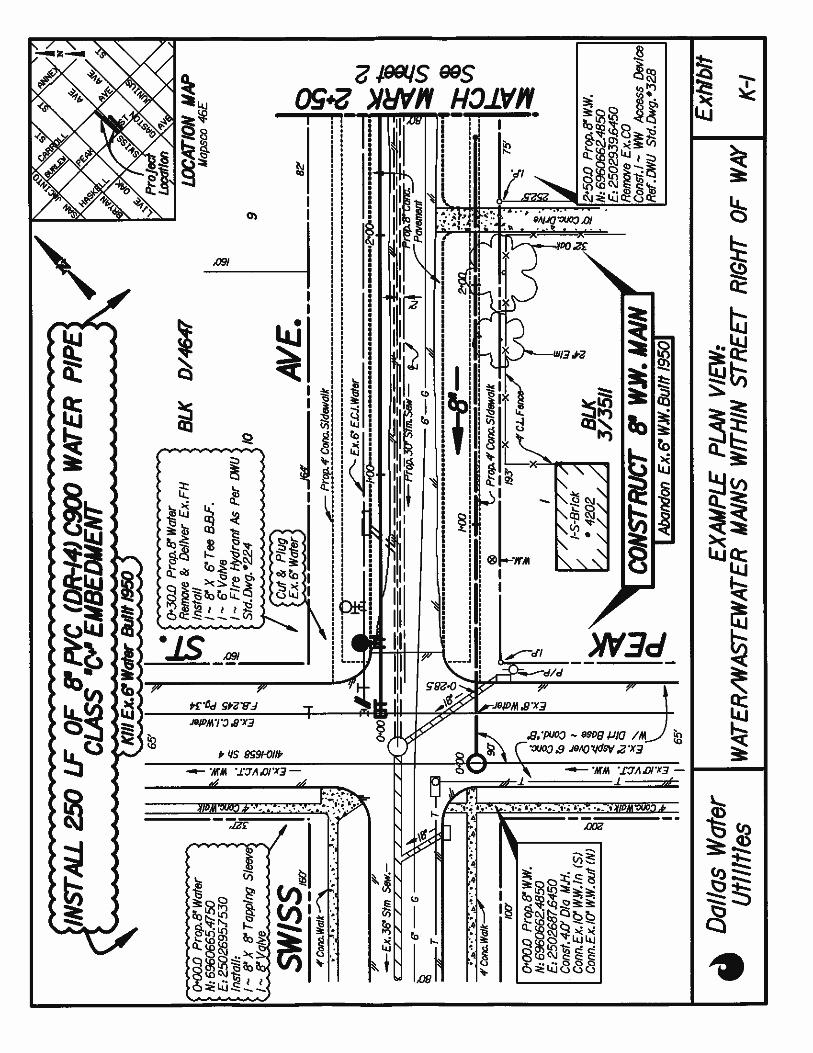
EXHIBIT K.1 EXAMPLE PLAN VIEW: WATER/WASTEWATER MAINS WITHIN STREET RIGHT-OF-WAY
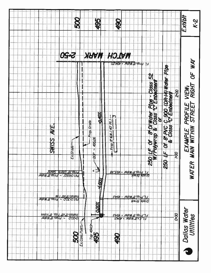
EXHIBIT K.2 EXAMPLE PROFILE VIEW: WATER MAIN WITHIN STREET RIGHT-OF-WAY
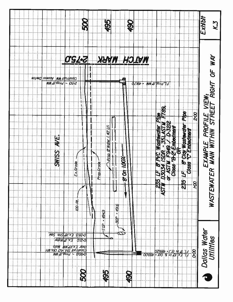
EXHIBIT K.3 EXAMPLE PROFILE VIEW: WASTEWATER MAIN WITHIN STREET RIGHT-OF-WAY
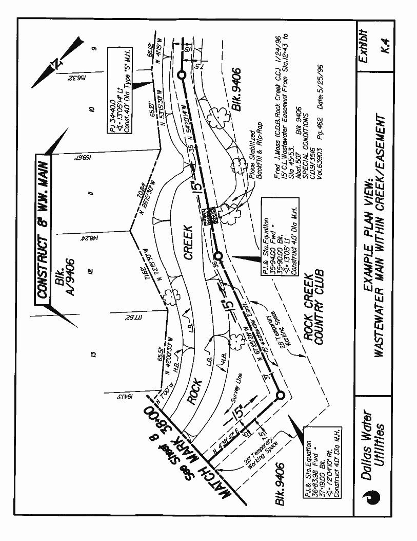
EXHIBIT K.4 EXAMPLE PLAN VIEW: WASTEWATER MAIN WITHIN CREEK/EASEMENT
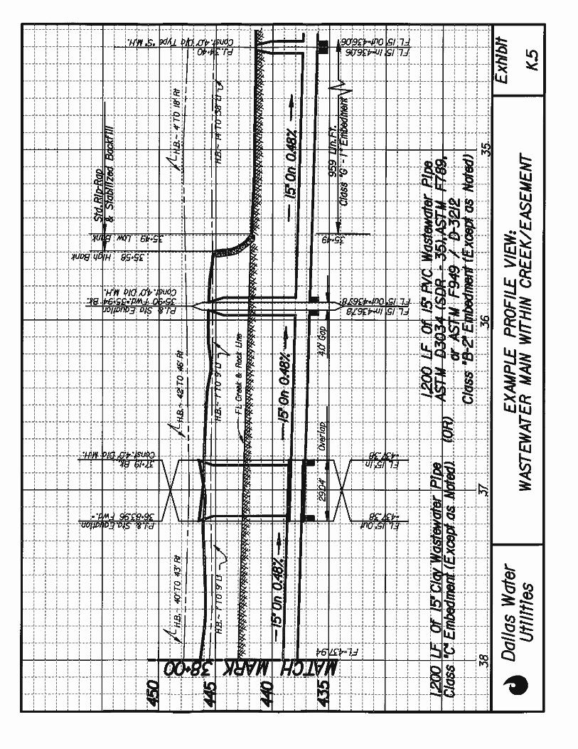
EXHIBIT K.5 EXAMPLE PROFILE VIEW: WASTEWATER MAIN WITHIN CREEK
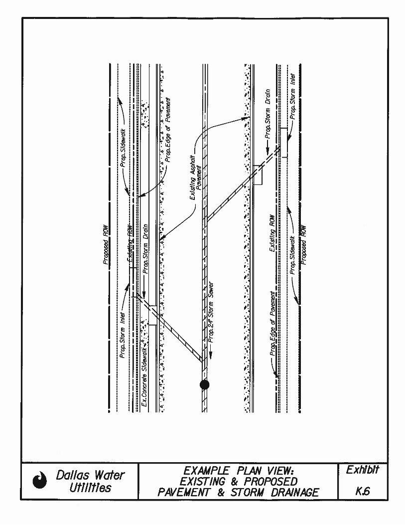
EXHIBIT K-6 EXAMPLE PLAN VIEW: EXIST./PROP. PAVEMENT AND STORM DRAINS
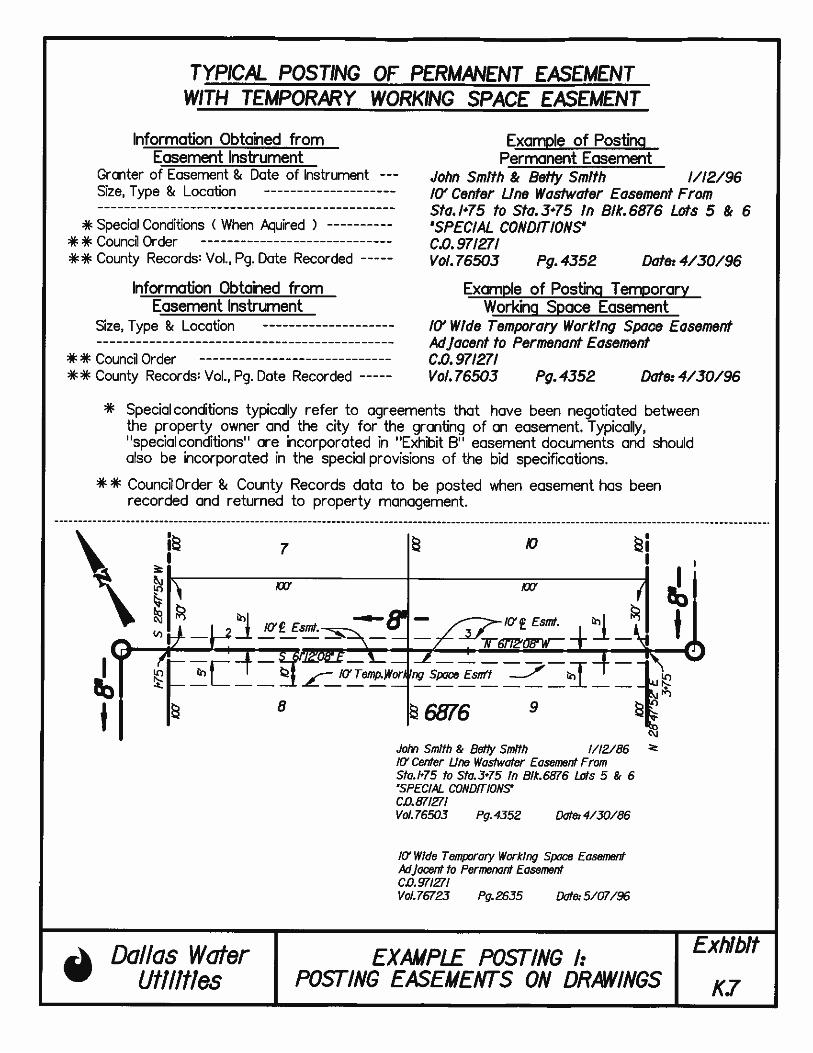
EXHIBIT K.7 EXAMPLE POSTING 1: POSTING EASEMENTS ON DRAWING
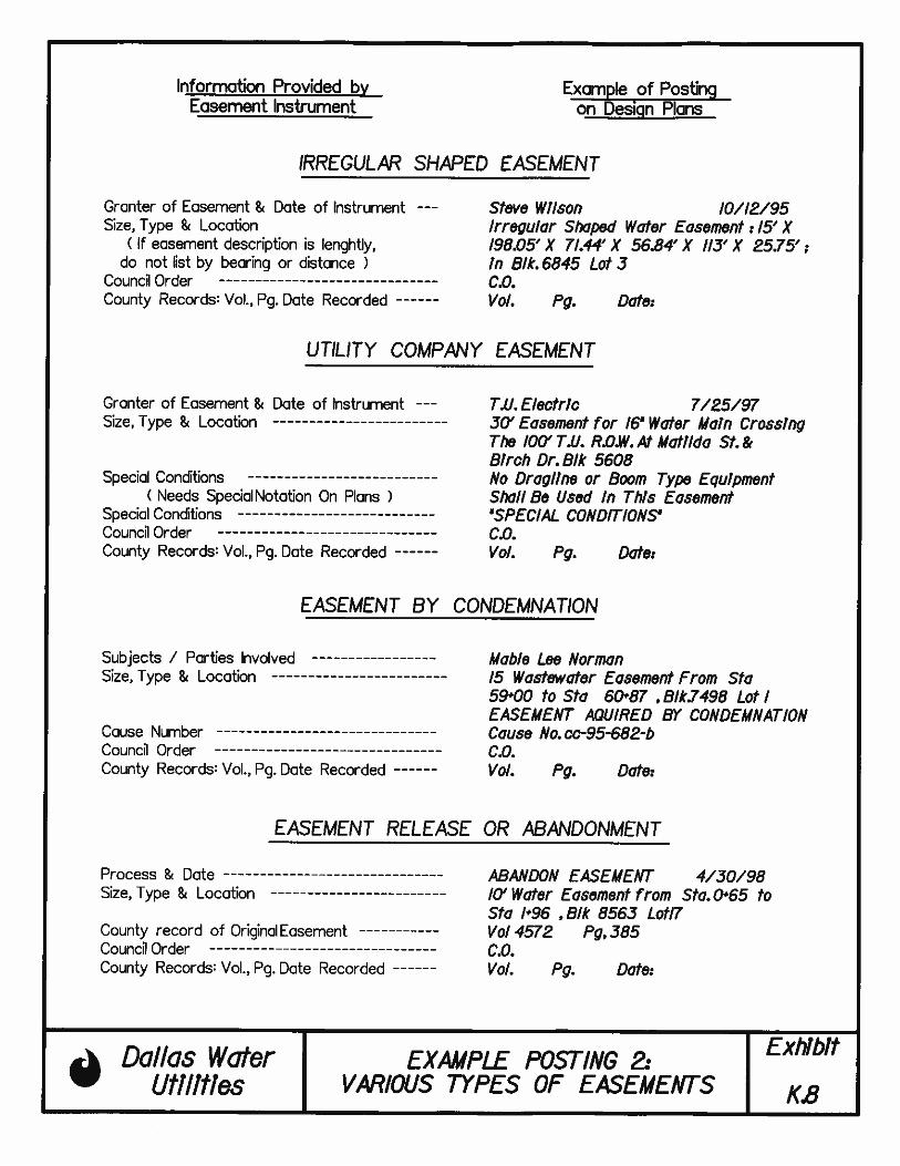
EXHIBIT K. 8 EXAMPLE POSTING 2: VARIOUS TYPES OF EASEMENTS
EXHIBIT K. 9 EXAMPLE POSTING 3: POSTING OF APPROVALS, AGREEMENTS & RELEASES
DWU PIPELINE DRAFTING STANDARDS P-1 OCTOBER 2011
LIST OF APPENDICES
APPENDIX A.1 SURVEY CHECKLIST
APPENDIX A.2 BASEMAP CHECKLIST
APPENDIX A.3 DESIGN CHECKLIST
APPENDIX A.4 AS-BUILT DRAWING CHECKLIST
APPENDIX A.5 RECORD DRAWING CHECKLIST
APPENDIX B.100 PREDEFINED LEVELS: CIVIL- WATER (C_WATER)
APPENDIX B.200 PREDEFINED LEVELS: CIVIL- WASTEWATER (C_WASTEWATER)
APPENDIX B.300 PREDEFINED LEVELS: CIVIL- TRAFFIC (C_TRAFFIC)
APPENDIX B.400 PREDEFINED LEVELS: CIVIL- PAVING (C_PAVING)
APPENDIX B.500 PREDEFINED LEVELS: CIVIL- STORM (C_STORM)
APPENDIX B.1000 PREDEFINED LEVELS: SURVEY- PROPERTY (C_PROPERTY)
APPENDIX B.2000 PREDEFINED LEVELS: SURVEY- PAVEMENT (V_PVMT)
APPENDIX B.3000 PREDEFINED LEVELS: SURVEY- RAIL (V_ RAIL), BUILDING (V_BLDG),
CONTROL (V_CTRL), TOPOGRAPHY (V_TOPO), TRAFFIC (V_TRAF)
APPENDIX B.4000 PREDEFINED LEVELS: SURVEY- WATER (V_WATER)
APPENDIX B.5000 PREDEFINED LEVELS: SURVEY- WASTEWATER (V_WW)
APPENDIX B.6000 PREDEFINED LEVELS: SURVEY- STORM (V_STRM), UTILITY (V_UTILITY)
APPENDIX B.7000 PREDEFINED LEVELS: SURVEY- DESIGN (V_DESIGN)
APPENDIX B.8000 PREDEFINED LEVELS: SURVEY- TRAINGULATION, (V_TRIANGULATION,
V_DTM, V_CONTOUR)
DWU PIPELINE DRAFTING STANDARDS P-2 OCTOBER 2011
PREFACE
P.1 BACKGROUND
The intent of this manual is to provide a consistent graphic management guideline for design and drafting of all water and wastewater main projects owned and operated by Dallas Water Utilities (DWU). This manual replaces the second edition of “Drafting Standards for Pipeline Projects” by DWU dated January, 1998. The chronological list of events in developing this manual is summarized as follows: JAN, 1988 FIRST EDITION: Compilation of drafting instructions into first edition
of the manual. JAN, 1998 SECOND EDITION: Revision of the 1988 manual to include standard plan
format, computer aided drafting and design (CADD) settings and sample drawings.
OCT, 2010 THIRD EDITION: Revision of the 1998 manual to incorporate updated
general requirements, drafting conventions, drawing configurations, CADD settings and custom seed file with predefined levels, text style, cell library and other features.
OCT, 2011: Revision of the 2010 manual to correct minor errors
in the text, add illustrations, update the cell library and revise the level library so the colors for underground utilities correspond with the American Public Works Association Uniform Color Code for Marking Underground Utility Lines.
This October 2011 of “Drafting Standards for Water/Wastewater Pipeline Projects” is written by Engineering Services, Dallas Water Utilities. Any questions or suggestions regarding to this manual should be forwarded to Engineering Services, Dallas Water Utilities.
DWU PIPELINE DRAFTING STANDARDS P-3 OCTOBER 2011
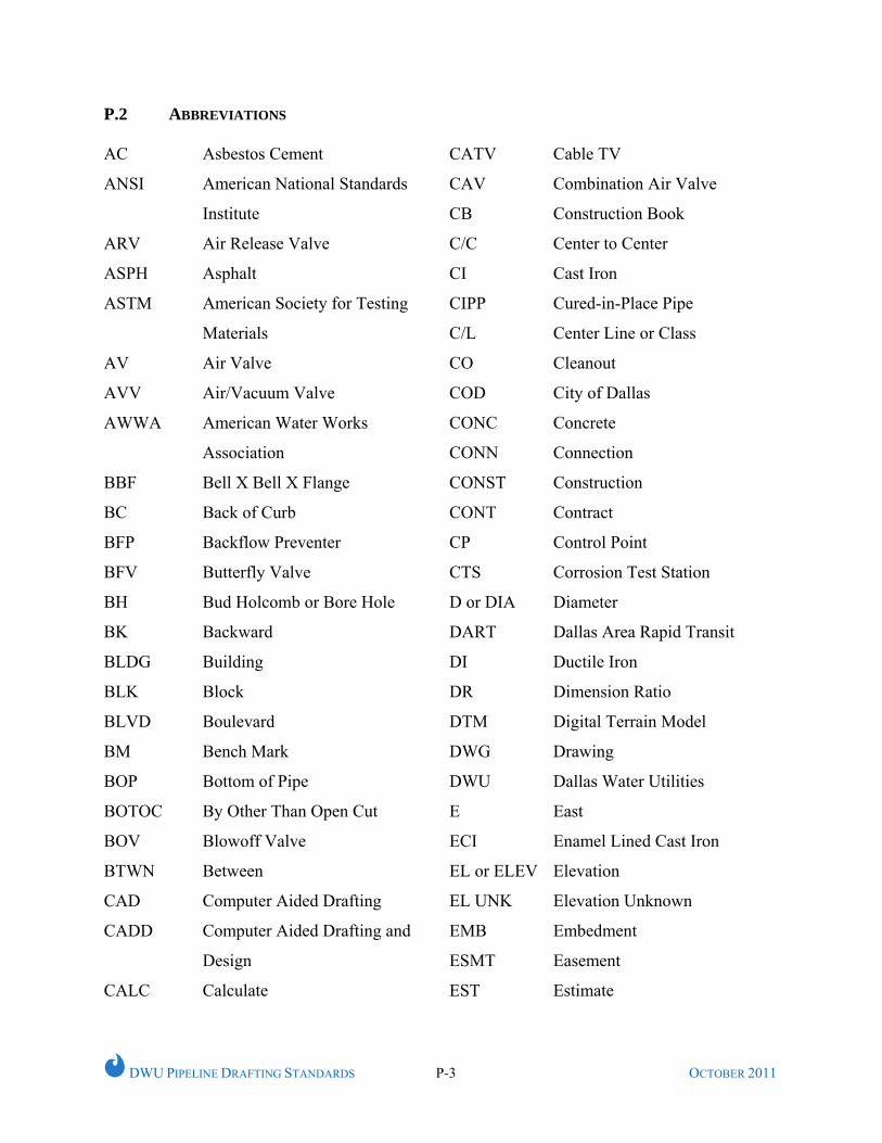
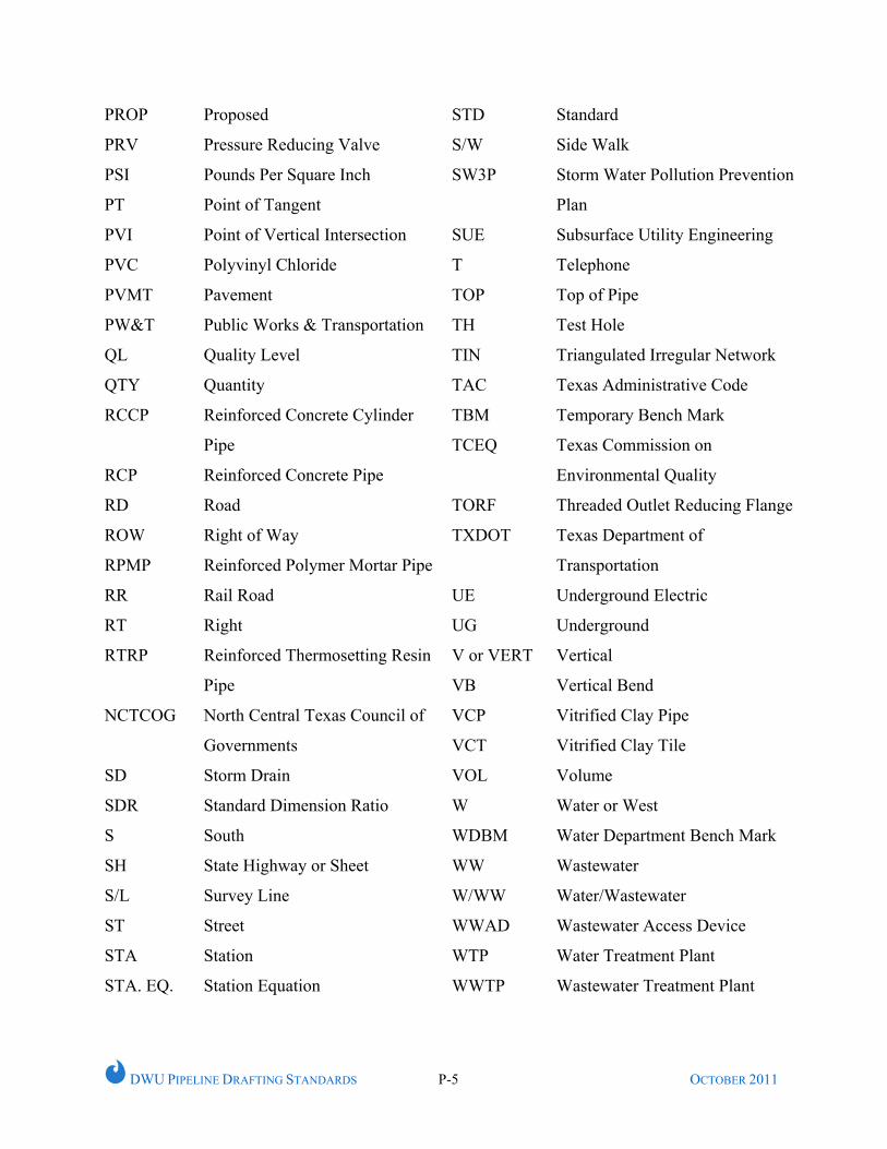
P.2 ABBREVIATIONS AC
ANSI
ARV
ASPH
ASTM
AV
AVV
AWWA
BBF
BC
BFP
BFV
BH
BK
BLDG
BLK
BLVD
BM
BOP
BOTOC
BOV
BTWN
CAD
CADD
CALC
Asbestos Cement
American National Standards
Institute
Air Release Valve
Asphalt
American Society for Testing
Materials
Air Valve
Air/Vacuum Valve
American Water Works
Association
Bell X Bell X Flange
Back of Curb
Backflow Preventer
Butterfly Valve
Bud Holcomb or Bore Hole
Backward
Building
Block
Boulevard
Bench Mark
Bottom of Pipe
By Other Than Open Cut
Blowoff Valve
Between
Computer Aided Drafting
Computer Aided Drafting and
Design
Calculate
CATV
CAV
CB
C/C
CI
CIPP
C/L
CO
COD
CONC
CONN
CONST
CONT
CP
CTS
D or DIA
DART
DI
DR
DTM
DWG
DWU
E
ECI
EL or ELEV
EL UNK
EMB
ESMT
EST
Cable TV
Combination Air Valve
Construction Book
Center to Center
Cast Iron
Cured-in-Place Pipe
Center Line or Class
Cleanout
City of Dallas
Concrete
Connection
Construction
Contract
Control Point
Corrosion Test Station
Diameter
Dallas Area Rapid Transit
Ductile Iron
Dimension Ratio
Digital Terrain Model
Drawing
Dallas Water Utilities
East
Enamel Lined Cast Iron
Elevation
Elevation Unknown
Embedment
Easement
Estimate
DWU PIPELINE DRAFTING STANDARDS P-4 OCTOBER 2011
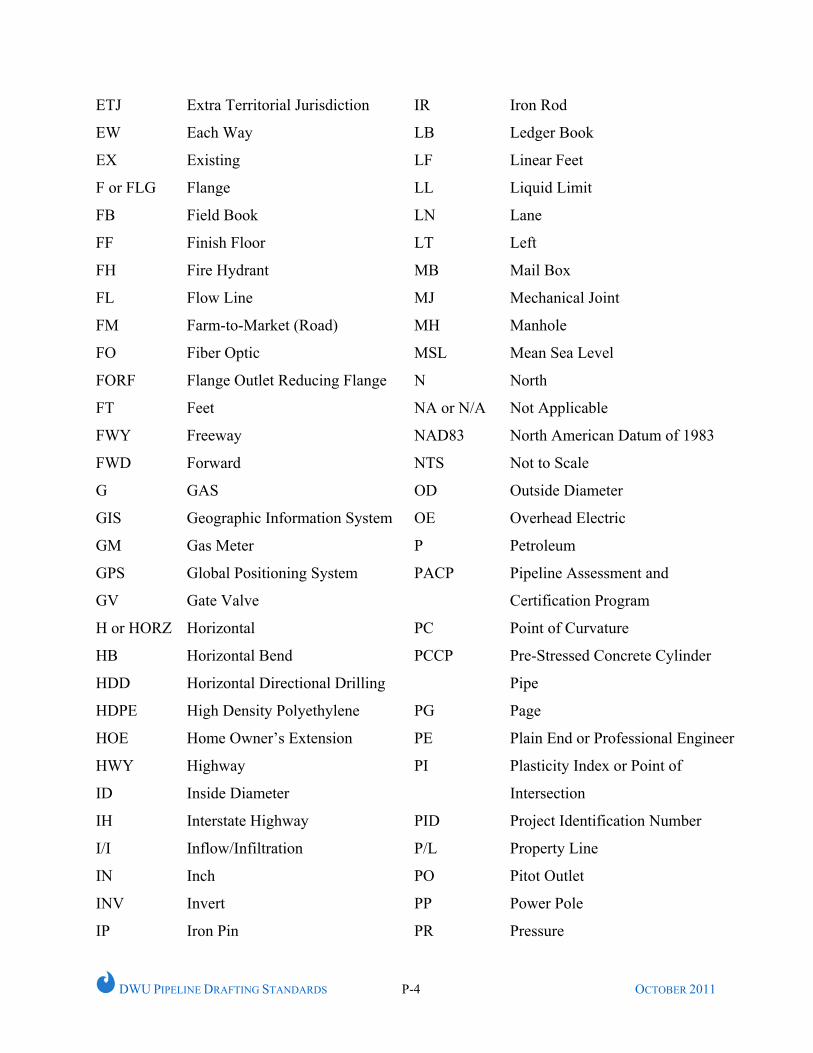
ETJ
EW
EX
F or FLG
FB
FF
FH
FL
FM
FO
FORF
FT
FWY
FWD
G
GIS
GM
GPS
GV
H or HORZ
HB
HDD
HDPE
HOE
HWY
ID
IH
I/I
IN
INV
IP
Extra Territorial Jurisdiction
Each Way
Existing
Flange
Field Book
Finish Floor
Fire Hydrant
Flow Line
Farm-to-Market (Road)
Fiber Optic
Flange Outlet Reducing Flange
Feet
Freeway
Forward
GAS
Geographic Information System
Gas Meter
Global Positioning System
Gate Valve
Horizontal
Horizontal Bend
Horizontal Directional Drilling
High Density Polyethylene
Home Owner’s Extension
Highway
Inside Diameter
Interstate Highway
Inflow/Infiltration
Inch
Invert
Iron Pin
IR
LB
LF
LL
LN
LT
MB
MJ
MH
MSL
N
NA or N/A
NAD83
NTS
OD
OE
P
PACP
PC
PCCP
PG
PE
PI
PID
P/L
PO
PP
PR
Iron Rod
Ledger Book
Linear Feet
Liquid Limit
Lane
Left
Mail Box
Mechanical Joint
Manhole
Mean Sea Level
North
Not Applicable
North American Datum of 1983
Not to Scale
Outside Diameter
Overhead Electric
Petroleum
Pipeline Assessment and
Certification Program
Point of Curvature
Pre-Stressed Concrete Cylinder
Pipe
Page
Plain End or Professional Engineer
Plasticity Index or Point of
Intersection
Project Identification Number
Property Line
Pitot Outlet
Power Pole
Pressure
DWU PIPELINE DRAFTING STANDARDS P-5 OCTOBER 2011
PROP
PRV
PSI
PT
PVI
PVC
PVMT
PW&T
QL
QTY
RCCP
RCP
RD
ROW
RPMP
RR
RT
RTRP
NCTCOG
SD
SDR
S
SH
S/L
ST
STA
STA. EQ.
Proposed
Pressure Reducing Valve
Pounds Per Square Inch
Point of Tangent
Point of Vertical Intersection
Polyvinyl Chloride
Pavement
Public Works & Transportation
Quality Level
Quantity
Reinforced Concrete Cylinder
Pipe
Reinforced Concrete Pipe
Road
Right of Way
Reinforced Polymer Mortar Pipe
Rail Road
Right
Reinforced Thermosetting Resin
Pipe
North Central Texas Council of
Governments
Storm Drain
Standard Dimension Ratio
South
State Highway or Sheet
Survey Line
Street
Station
Station Equation
STD
S/W
SW3P
SUE
T
TOP
TH
TIN
TAC
TBM
TCEQ
TORF
TXDOT
UE
UG
V or VERT
VB
VCP
VCT
VOL
W
WDBM
WW
W/WW
WWAD
WTP
WWTP
Standard
Side Walk
Storm Water Pollution Prevention
Plan
Subsurface Utility Engineering
Telephone
Top of Pipe
Test Hole
Triangulated Irregular Network
Texas Administrative Code
Temporary Bench Mark
Texas Commission on
Environmental Quality
Threaded Outlet Reducing Flange
Texas Department of
Transportation
Underground Electric
Underground
Vertical
Vertical Bend
Vitrified Clay Pipe
Vitrified Clay Tile
Volume
Water or West
Water Department Bench Mark
Wastewater
Water/Wastewater
Wastewater Access Device
Water Treatment Plant
Wastewater Treatment Plant
DWU PIPELINE DRAFTING STANDARDS 1-1 OCTOBER 2011
CHAPTER 1
GENERAL REQUIREMENTS
1.1 INTRODUCTION
This chapter outlines the general drafting standards to be adopted in all water and
wastewater pipeline design projects for Dallas Water Utilities (DWU).
1.2 SOFTWARE APPLICATION
MicroStation V8 XM or the latest edition shall be used for design and drafting of all
DWU water and wastewater main projects. All drawings used by or provided to DWU
shall be in “dgn” format. In addition, the latest version of InRoads or equivalent
software(s) as approved by DWU, shall be used to perform survey data import, surface
modeling, horizontal and vertical alignment, and other related tasks for water and
wastewater main design.
1.3 DATA COLLECTION AND DRAWING CHECKLIST
All survey for design and subsequent various forms of drawings shall be prepared in
accordance with DWU standards as specified in this section.
1.3.1 SURVEY
Survey shall be conducted prior to initiation of any detailed design. The majority of the
existing topographic features shall be obtained from the survey. Existing and proposed
utility information shall initially be obtained from the utility records supplied by each
utility company. In addition, the location of existing utilities shall be confirmed by
survey or field investigation as necessary. A general checklist for water and
wastewater main survey is included under APPENDIX A.1.
1.3.2 BASEMAP
A basemap shall be prepared to create a design basis for water and wastewater main
projects. A general checklist for water and wastewater main basemap is included under
APPENDIX A.2.
DWU PIPELINE DRAFTING STANDARDS 1-2 OCTOBER 2011
1.3.3 DESIGN PLAN
All water and wastewater pipeline drawings shall be prepared in accordance with the
DWU Water and Wastewater Pipeline Design Manual, Latest Edition. A typical
checklist for water and wastewater main design plans is included under APPENDIX A.3.
1.3.4 AS-BUILT DRAWING
As-built drawings shall consist of handwritten notes demonstrating any field changes
during construction. A general checklist for water and wastewater main as-built
drawings is included under APPENDIX A.4.
1.3.5 RECORD DRAWING
Record drawings shall be prepared by the designer showing any field changes as
marked on the as-built drawings. A typical checklist for water and wastewater main
record drawings is included under APPENDIX A.5.
1.4 FILE MANAGEMENT
All MicroStation files associated with water and wastewater design shall be properly
named as described in this section.
1.4.1 NAMING CONVENTIONS
A typical water and wastewater drawing file shall be named as follows:
“Drawing Type-Project Identifier.File Extension”
Where, “Drawing Type” shall include abbreviation for DWU 3D Seed File
(DWUSeed3D), DWU 2D Seed File (DWUSeed2D), 3D Base Map (Basemap3D), 2D
Base Map (Basemap2D), Cover Sheet (C), General Sheet (G), Design Sheet (D),
Traffic Control Sheet (T), or other relevant drawings. “Project Identifier” includes
project identification (PID) number, construction contract (CONT) number, street
name, project area name, or unique DWU Water/Wastewater file number. In addition,
“File Extension” typically denotes to “DGN” for all MicroStation drawings.
DWU PIPELINE DRAFTING STANDARDS 1-3 OCTOBER 2011
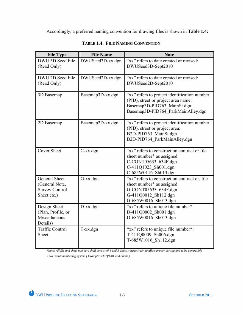
Accordingly, a preferred naming convention for drawing files is shown in Table 1.4:
TABLE 1.4: FILE NAMING CONVENTION
File Type File Name Note DWU 3D Seed File (Read Only)
DWUSeed3D-xx.dgn “xx” refers to date created or revised: DWUSeed3D-Sept2010
DWU 2D Seed File (Read Only)
DWUSeed2D-xx.dgn “xx” refers to date created or revised: DWUSeed2D-Sept2010
3D Basemap Basemap3D-xx.dgn “xx” refers to project identification number (PID), street or project area name: Basemap3D-PID763_MainSt.dgn Basemap3D-PID764_ParkMainAlley.dgn
2D Basemap Basemap2D-xx.dgn “xx” refers to project identification number (PID), street or project area: B2D-PID763_MainSt.dgn B2D-PID764_ParkMainAlley.dgn
Cover Sheet C-xx.dgn “xx” refers to construction contract or file sheet number* as assigned: C-CONT05633_634F.dgn C-411Q1023_Sh001.dgn C-685W0116_Sh013.dgn
General Sheet (General Note, Survey Control Sheet etc.)
G-xx.dgn “xx” refers to construction contract or, file sheet number* as assigned: G-CONT05633_634F.dgn G-411Q0012_Sh112.dgn G-685W0016_Sh013.dgn
Design Sheet (Plan, Profile, or Miscellaneous Details)
D-xx.dgn “xx” refers to unique file number*: D-411Q0002_Sh001.dgn D-685W0016_Sh013.dgn
Traffic Control Sheet
T-xx.dgn “xx” refers to unique file number*: T-411Q0009_Sh006.dgn T-685W1016_Sh112.dgn
*Note: All file and sheet numbers shall consist of 4 and 3 digits, respectively, to allow proper sorting and to be compatible
DWU vault numbering system ( Example: 411Q0001 and Sh001)
DWU PIPELINE DRAFTING STANDARDS 1-4 OCTOBER 2011
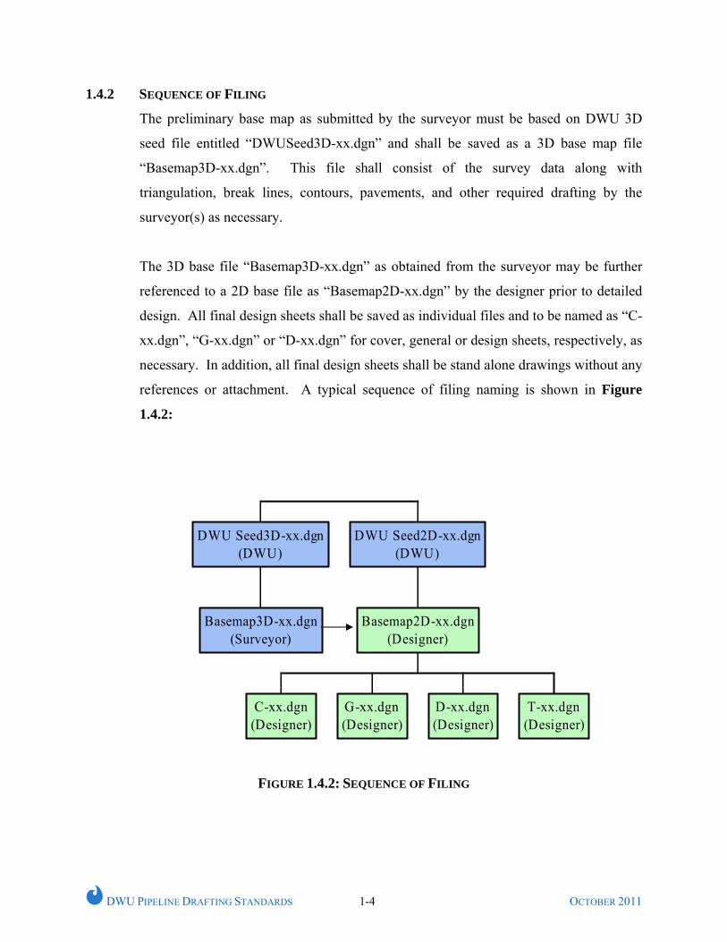
1.4.2 SEQUENCE OF FILING
The preliminary base map as submitted by the surveyor must be based on DWU 3D
seed file entitled “DWUSeed3D-xx.dgn” and shall be saved as a 3D base map file
“Basemap3D-xx.dgn”. This file shall consist of the survey data along with
triangulation, break lines, contours, pavements, and other required drafting by the
surveyor(s) as necessary.
The 3D base file “Basemap3D-xx.dgn” as obtained from the surveyor may be further
referenced to a 2D base file as “Basemap2D-xx.dgn” by the designer prior to detailed
design. All final design sheets shall be saved as individual files and to be named as “C-
xx.dgn”, “G-xx.dgn” or “D-xx.dgn” for cover, general or design sheets, respectively, as
necessary. In addition, all final design sheets shall be stand alone drawings without any
references or attachment. A typical sequence of filing naming is shown in Figure
1.4.2:
Basemap3D-xx.dgn(Surveyor)
DWU Seed3D-xx.dgn(DWU)
C-xx.dgn(Designer)
G-xx.dgn(Designer)
D-xx.dgn(Designer)
T-xx.dgn(Designer)
Basemap2D-xx.dgn(Designer)
DWU Seed2D-xx.dgn(DWU)
FIGURE 1.4.2: SEQUENCE OF FILING
DWU PIPELINE DRAFTING STANDARDS 2-2 OCTOBER 2011
CHAPTER 2
DRAFTING CONVENTIONS
2.1 GENERAL
This Chapter describes basic drafting conventions to be used for water and wastewater
main projects.
2.2 DRAFTING BASE POINTS
All DWU projects shall use City of Dallas Benchmarks for vertical control. The list of
City of Dallas Benchmarks is available at the City of Dallas Website. In addition, all
survey coordinates shall be tied to State Plane Coordinates, North Central Zone, North
American Datum of 1983 (NAD83). This will facilitate use of various design elements
into the City of Dallas Geographical Information System (GIS) system.
The coordinate system used for design shall match that used by the surveyor for data
collection and these coordinates shall not be rotated or translated. MicroStation X, Y
base point of 0, 0 should match a Northing, Easting of 0, 0.
2.3 MASTER MODEL AND SHEET MODEL
All drafting shall be done at 1:1, in engineering units, in the MicroStation “master
model” environment. The design along with standard border shall be referenced in a
“sheet model” prior to plotting using appropriate scale factor, as necessary.
2.4 REFERENCES
References shall be used wherever a part of the basemap or other information will be
used in more than one drawing, so that any changes are automatically updated in all of
the associated drawings. However, upon completion of final design, each design sheet
shall be a stand alone drawing without any references or attachments and shall be
named as per Table 1.4. This will provide assured future retrieval of all information
that is contained on the engineer’s sealed hard copy.
DWU PIPELINE DRAFTING STANDARDS 2-2 OCTOBER 2011
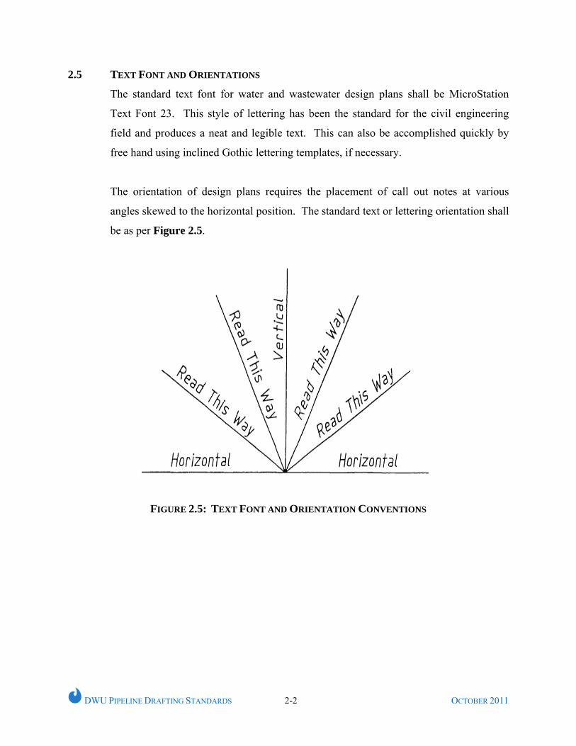
2.5 TEXT FONT AND ORIENTATIONS
The standard text font for water and wastewater design plans shall be MicroStation
Text Font 23. This style of lettering has been the standard for the civil engineering
field and produces a neat and legible text. This can also be accomplished quickly by
free hand using inclined Gothic lettering templates, if necessary.
The orientation of design plans requires the placement of call out notes at various
angles skewed to the horizontal position. The standard text or lettering orientation shall
be as per Figure 2.5.
FIGURE 2.5: TEXT FONT AND ORIENTATION CONVENTIONS
DWU PIPELINE DRAFTING STANDARDS 2-3 OCTOBER 2011
2.6 ANNOTATIONS
Unusually large text shall not be used, except decorative fonts on cover sheet.
Annotation associated with any feature shall be at line style 0 (solid) and weight of 0.
Center left justification shall be used for blocks of text. In addition, following
guideline shall be used for annotations associated with features:
• Move annotation away from feature
• Line up annotation if possible
• Avoid odd abbreviations and squeezing text to fit
• Break leader lines at conflicts only
• Multiple leader lines may not intersect
• Group leader lines at about the same angle for neatness
2.7 EXISTING, PROPOSED AND FUTURE FEATURES
All existing, proposed or future features shall be clearly distinguishable from each
other. Following guidelines shall be used except otherwise predefined by DWU:
2.7.1 Existing Features:
All the existing features shall be depicted with relatively thinner lines than proposed or
future features of the same type. Grey scales are generally not allowed because of their
tendency to be lost during typical reproduction or photocopying processes.
2.7.2 Proposed Features:
All proposed features shall be more prominently depicted than existing features for the
same type.
2.7.3 Future Features:
All future features shall be more prominently depicted than existing features for the
same type. Typically, future features shall be at line style of 5 (short dash) and
minimum weight of 2 (0.024 in) unless otherwise predefined by DWU.
DWU PIPELINE DRAFTING STANDARDS 2-4 OCTOBER 2011
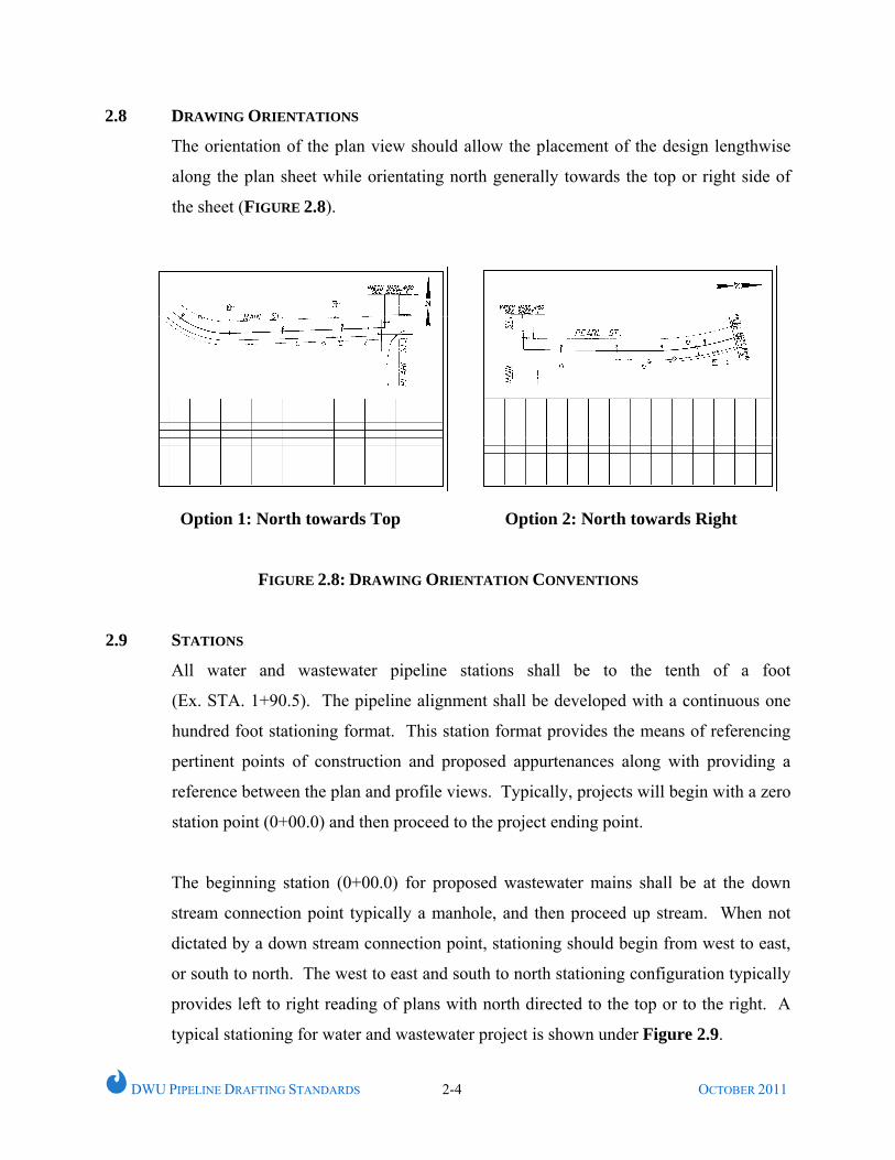
2.8 DRAWING ORIENTATIONS
The orientation of the plan view should allow the placement of the design lengthwise
along the plan sheet while orientating north generally towards the top or right side of
the sheet (FIGURE 2.8).
Option 1: North towards Top Option 2: North towards Right
FIGURE 2.8: DRAWING ORIENTATION CONVENTIONS
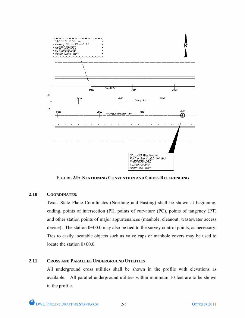
2.9 STATIONS
All water and wastewater pipeline stations shall be to the tenth of a foot
(Ex. STA. 1+90.5). The pipeline alignment shall be developed with a continuous one
hundred foot stationing format. This station format provides the means of referencing
pertinent points of construction and proposed appurtenances along with providing a
reference between the plan and profile views. Typically, projects will begin with a zero
station point (0+00.0) and then proceed to the project ending point.
The beginning station (0+00.0) for proposed wastewater mains shall be at the down
stream connection point typically a manhole, and then proceed up stream. When not
dictated by a down stream connection point, stationing should begin from west to east,
or south to north. The west to east and south to north stationing configuration typically
provides left to right reading of plans with north directed to the top or to the right. A
typical stationing for water and wastewater project is shown under Figure 2.9.
DWU PIPELINE DRAFTING STANDARDS 2-5 OCTOBER 2011
FIGURE 2.9: STATIONING CONVENTION AND CROSS-REFERENCING
2.10 COORDINATES:
Texas State Plane Coordinates (Northing and Easting) shall be shown at beginning,
ending, points of intersection (PI), points of curvature (PC), points of tangency (PT)
and other station points of major appurtenances (manhole, cleanout, wastewater access
device). The station 0+00.0 may also be tied to the survey control points, as necessary.
Ties to easily locatable objects such as valve caps or manhole covers may be used to
locate the station 0+00.0.
2.11 CROSS AND PARALLEL UNDERGROUND UTILITIES
All underground cross utilities shall be shown in the profile with elevations as
available. All parallel underground utilities within minimum 10 feet are to be shown
in the profile.
DWU PIPELINE DRAFTING STANDARDS 2-6 OCTOBER 2011
2.12 SLOPE
Design slopes for all water and wastewater shall be nearest hundredth of a percent
(Example: Slope 5.20%). All proposed mains shall include the proposed slope and all
existing mains shall include the existing slope, if it is known.
2.13 ELEVATIONS
All proposed elevations shall be to the nearest hundredth of a foot
(Example: El. 495.95)
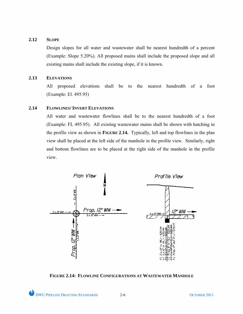
2.14 FLOWLINES/ INVERT ELEVATIONS
All water and wastewater flowlines shall be to the nearest hundredth of a foot
(Example: FL 495.95). All existing wastewater mains shall be shown with hatching in
the profile view as shown in FIGURE 2.14. Typically, left and top flowlines in the plan
view shall be placed at the left side of the manhole in the profile view. Similarly, right
and bottom flowlines are to be placed at the right side of the manhole in the profile
view.
FIGURE 2.14: FLOWLINE CONFIGURATIONS AT WASTEWATER MANHOLE
DWU PIPELINE DRAFTING STANDARDS 2-7 OCTOBER 2011
2.15 DRAWING SCALES
CAD drawings shall be developed at a 1:1 ratio and then plotted to the following scale
unless otherwise approved by DWU.
2.15.1 Horizontal Scale:
All plans shall be plotted at a horizontal scale of 1” = 20’ to show sufficient plan details
for congested project locations such as alleys, easements, or street right-of-ways with
numerous underground facilities. Generally, 1” = 20’ scale is most preferable;
however, 1” = 40’ may also be used for projects where the utilities are less congested.
2.15.2 Vertical Scale:
All profiles are to be plotted on the vertical scale of 1" = 6' with major horizontal lines
at five (5) foot intervals and to the same horizontal scale as the plan view.
2.15.3 Variance:
Special details, such as structures, may require the use of a scale which can provide
greater detail than those available on the standard civil engineer scale. For these
instances, the use of an appropriate architectural scale which provides greater detail is
acceptable.
2.16 MATCH MARKS
When a design spans more than one plan sheet, a design match mark must be
established to reference the continuation of the design from one sheet to another. The
following guidelines should be followed when establishing the location of match
marks:
• Match Marks are to be placed at half or full station points (e.g. 10+00.0 or
10+50.0). A quarter and three-quarter station points (e.g. 10+25.0 or 10+75.0) may
also be acceptable, if necessary.
• Match Marks are to be perpendicular to the design alignment at the station
referenced as the match mark point.
DWU PIPELINE DRAFTING STANDARDS 2-8 OCTOBER 2011
• When at all possible, place match marks outside of street intersections, highway
crossings, railroad crossings and areas of proposed construction by other than open
cut.
• Place match marks to maximize the use of the available plan and profile space
while considering any space requirements of location maps, general notes,
construction details, etc.
• Analyze the profile section at the proposed match mark and ensure that the location
of the match mark will not create any confusion in the profile view.
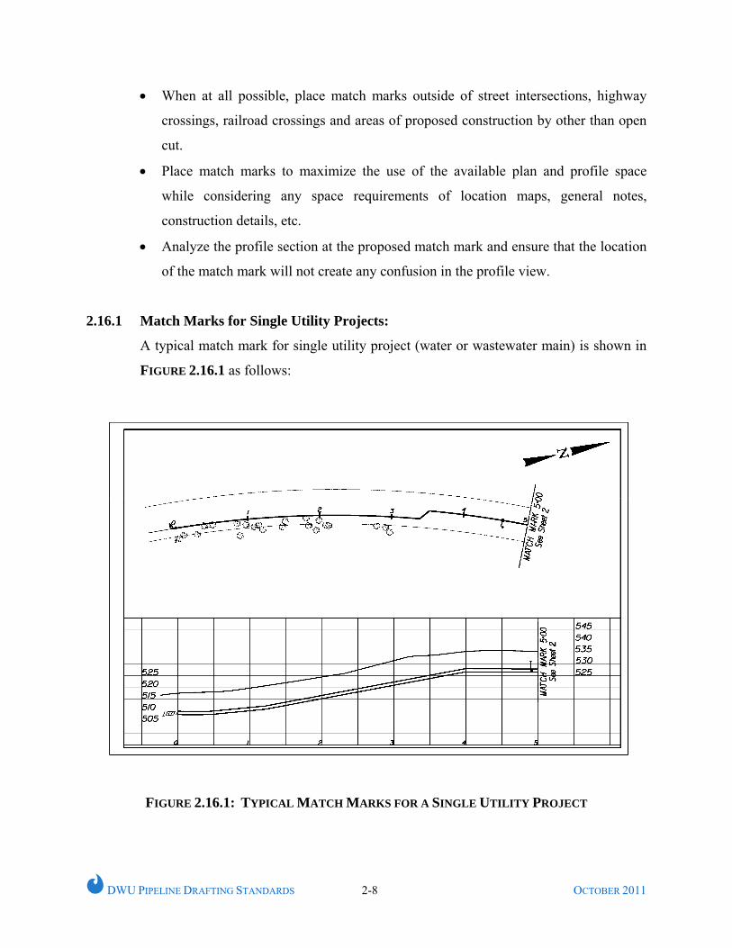
2.16.1 Match Marks for Single Utility Projects:
A typical match mark for single utility project (water or wastewater main) is shown in
FIGURE 2.16.1 as follows:
FIGURE 2.16.1: TYPICAL MATCH MARKS FOR A SINGLE UTILITY PROJECT
DWU PIPELINE DRAFTING STANDARDS 2-10 OCTOBER 2011
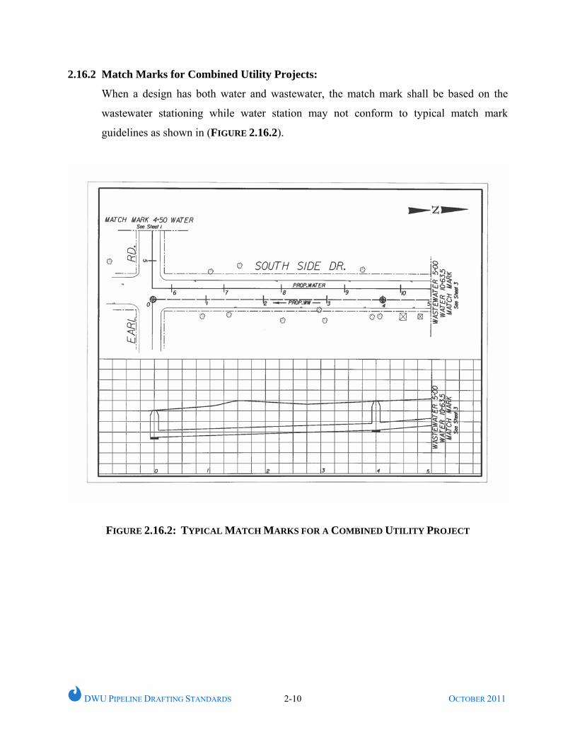
2.16.2 Match Marks for Combined Utility Projects:
When a design has both water and wastewater, the match mark shall be based on the
wastewater stationing while water station may not conform to typical match mark
guidelines as shown in (FIGURE 2.16.2).
FIGURE 2.16.2: TYPICAL MATCH MARKS FOR A COMBINED UTILITY PROJECT
DWU PIPELINE DRAFTING STANDARDS 2-10 OCTOBER 2011
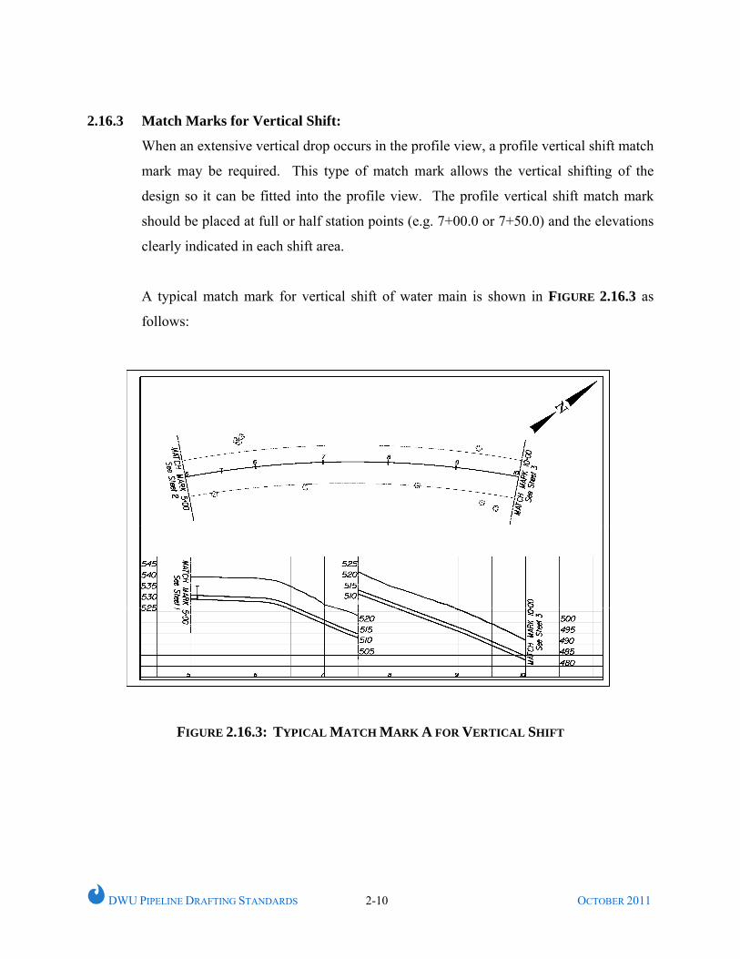
2.16.3 Match Marks for Vertical Shift:
When an extensive vertical drop occurs in the profile view, a profile vertical shift match
mark may be required. This type of match mark allows the vertical shifting of the
design so it can be fitted into the profile view. The profile vertical shift match mark
should be placed at full or half station points (e.g. 7+00.0 or 7+50.0) and the elevations
clearly indicated in each shift area.
A typical match mark for vertical shift of water main is shown in FIGURE 2.16.3 as
follows:
FIGURE 2.16.3: TYPICAL MATCH MARK A FOR VERTICAL SHIFT
X
DWU PIPELINE DRAFTING STANDARDS 3-1 OCTOBER 2011
CHAPTER 3
DRAWING CONFIGURATION
3.1 GENERAL
This chapter summarizes the basic configuration and various elements in the drawings
to be used for all DWU water and wastewater projects.
3.2 PLAN AND PROFILE CONFIGURATION
Three plan and profile configurations are available for developing design plans.
3.2.1 Combined Plans with Profile Sheet:
The combined plan and profile sheet is recommended for general use as it allows the
placement of the design plan view and profile view on the same sheet.
3.2.2 Full Plan Sheet:
The full plan sheet may be used when a combined plan and profile sheet does not
provide sufficient plan space or when a design can be developed independently of a
profile or when developing structural details. When a design requires a full plan sheet
and also needs a profile, then a full profile sheet must be included with the design. The
design must be thoroughly referenced to file, sheet, and line designation between the
plan sheet and the profile sheet.
3.2.3 Full Profile Sheet:
Full profile sheets may be used to provide supplemental profile space, if necessary.
DWU PIPELINE DRAFTING STANDARDS 3-2 OCTOBER 2011
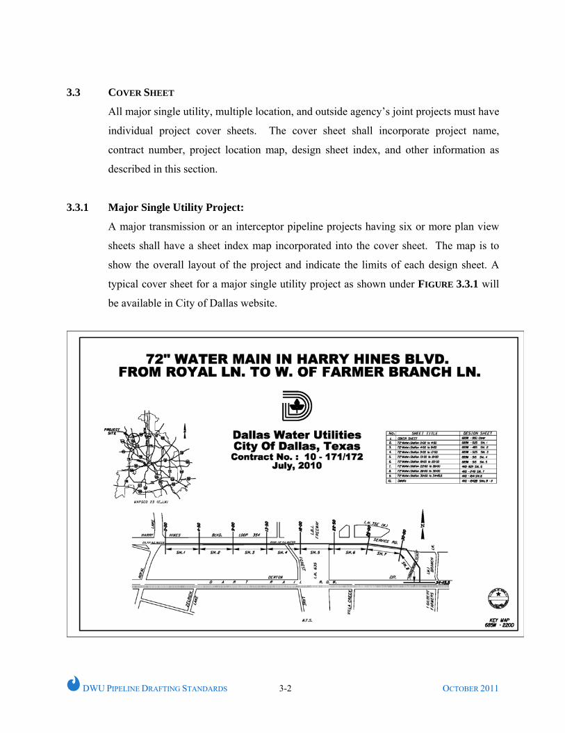
3.3 COVER SHEET
All major single utility, multiple location, and outside agency’s joint projects must have
individual project cover sheets. The cover sheet shall incorporate project name,
contract number, project location map, design sheet index, and other information as
described in this section.
3.3.1 Major Single Utility Project:
A major transmission or an interceptor pipeline projects having six or more plan view
sheets shall have a sheet index map incorporated into the cover sheet. The map is to
show the overall layout of the project and indicate the limits of each design sheet. A
typical cover sheet for a major single utility project as shown under FIGURE 3.3.1 will
be available in City of Dallas website.
DWU PIPELINE DRAFTING STANDARDS 3-2 OCTOBER 2011
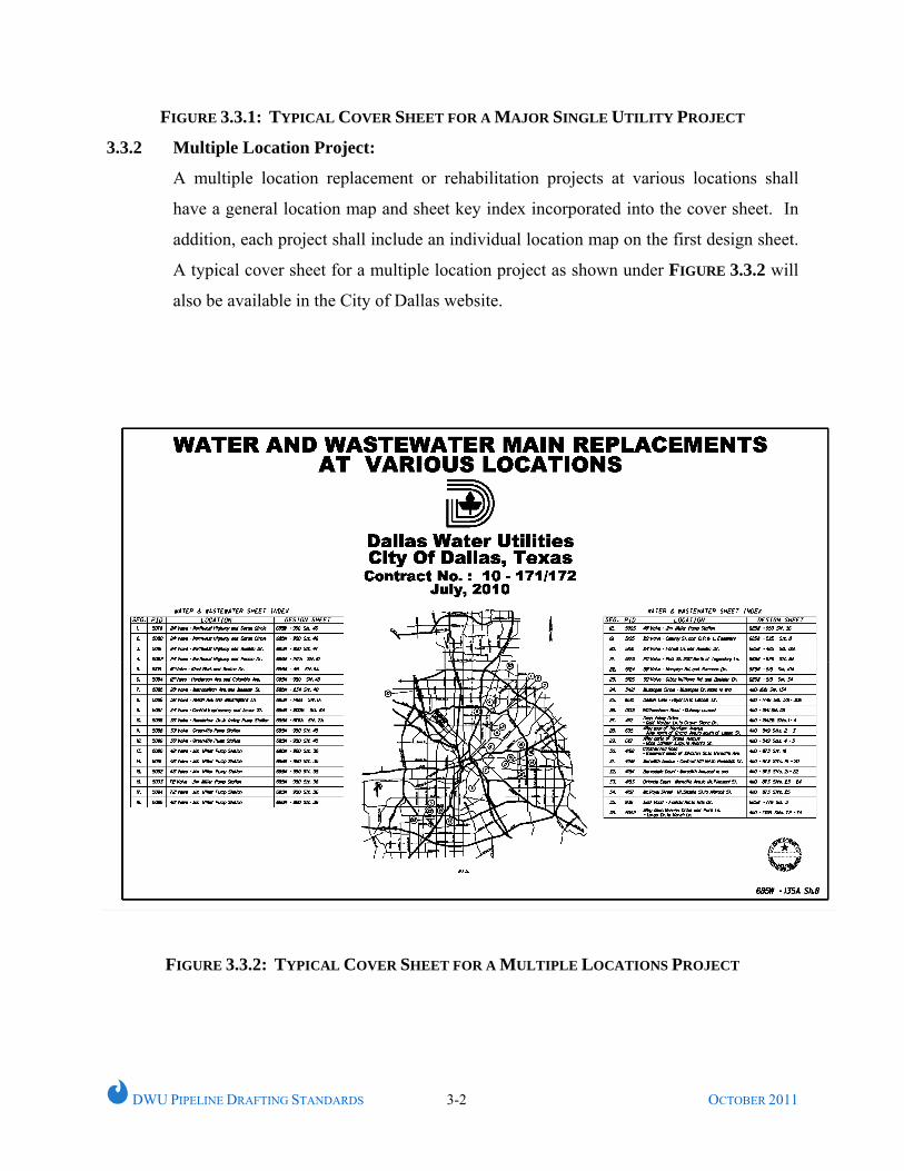
FIGURE 3.3.1: TYPICAL COVER SHEET FOR A MAJOR SINGLE UTILITY PROJECT
3.3.2 Multiple Location Project:
A multiple location replacement or rehabilitation projects at various locations shall
have a general location map and sheet key index incorporated into the cover sheet. In
addition, each project shall include an individual location map on the first design sheet.
A typical cover sheet for a multiple location project as shown under FIGURE 3.3.2 will
also be available in the City of Dallas website.
FIGURE 3.3.2: TYPICAL COVER SHEET FOR A MULTIPLE LOCATIONS PROJECT
DWU PIPELINE DRAFTING STANDARDS 3-4 OCTOBER 2011
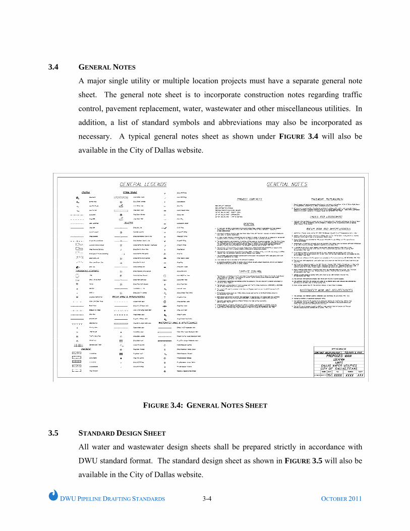
3.4 GENERAL NOTES
A major single utility or multiple location projects must have a separate general note
sheet. The general note sheet is to incorporate construction notes regarding traffic
control, pavement replacement, water, wastewater and other miscellaneous utilities. In
addition, a list of standard symbols and abbreviations may also be incorporated as
necessary. A typical general notes sheet as shown under FIGURE 3.4 will also be
available in the City of Dallas website.
FIGURE 3.4: GENERAL NOTES SHEET
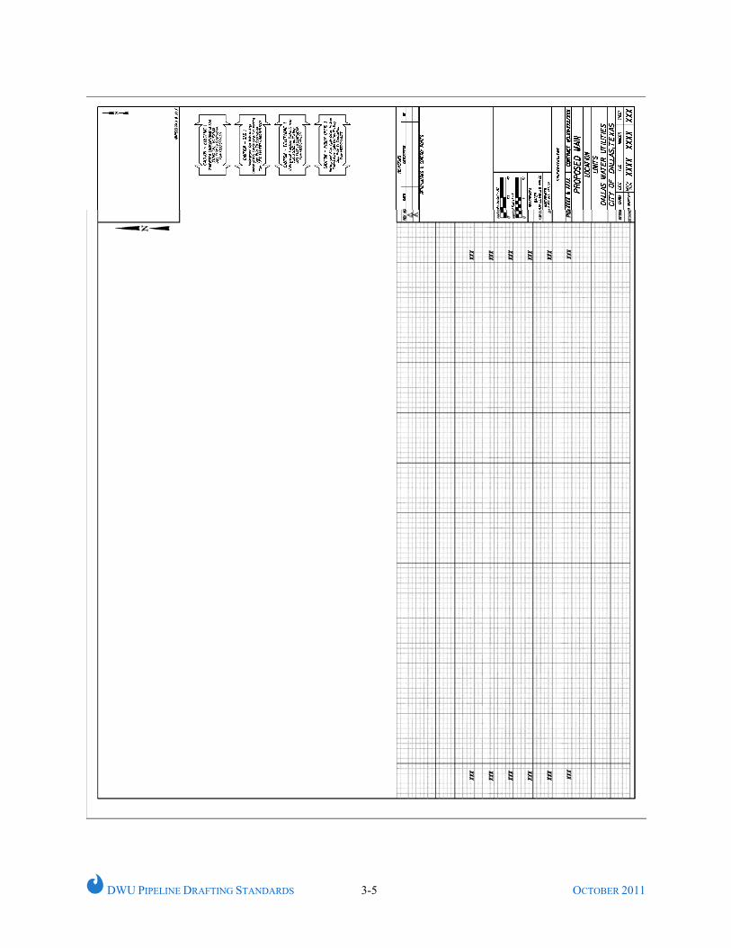
3.5 STANDARD DESIGN SHEET
All water and wastewater design sheets shall be prepared strictly in accordance with
DWU standard format. The standard design sheet as shown in FIGURE 3.5 will also be
available in the City of Dallas website.
DWU PIPELINE DRAFTING STANDARDS 3-5 OCTOBER 2011
DWU PIPELINE DRAFTING STANDARDS 3-5 OCTOBER 2011
FIGURE 3.5 STANDARD DESIGN SHEET
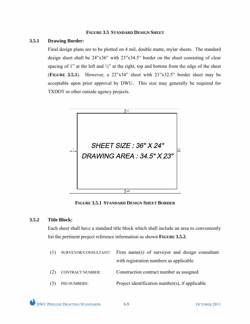
3.5.1 Drawing Border:
Final design plans are to be plotted on 4 mil, double matte, mylar sheets. The standard
design sheet shall be 24”x36” with 23”x34.5” border on the sheet consisting of clear
spacing of 1” at the left and ½” at the right, top and bottom from the edge of the sheet
(FIGURE 3.5.1). However, a 22”x34” sheet with 21”x32.5” border sheet may be
acceptable upon prior approval by DWU. This size may generally be required for
TXDOT or other outside agency projects.
FIGURE 3.5.1 STANDARD DESIGN SHEET BORDER
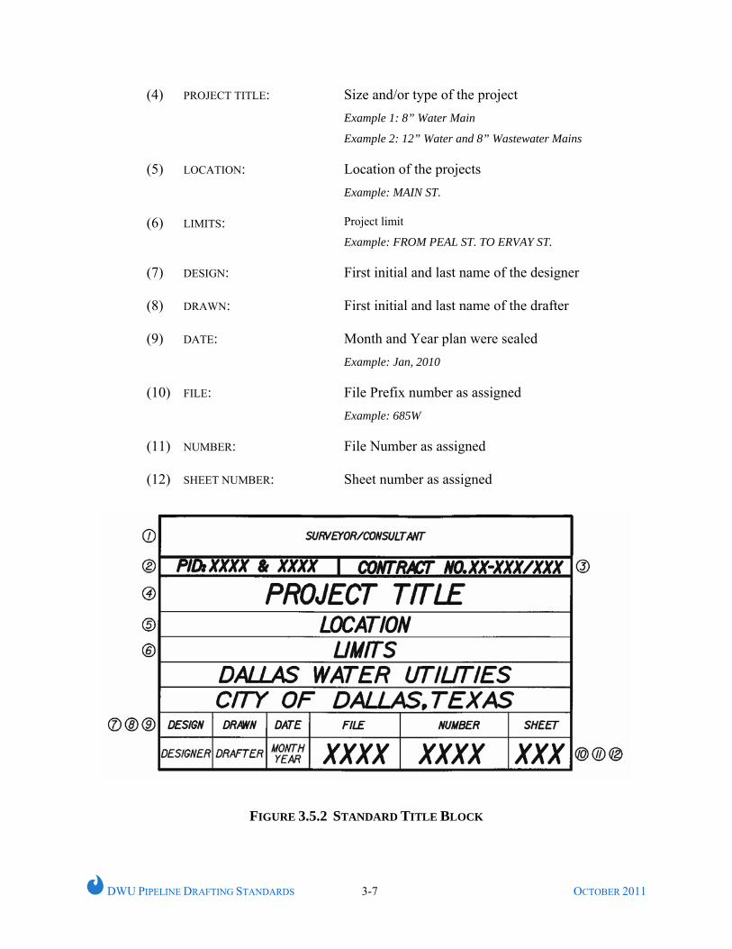
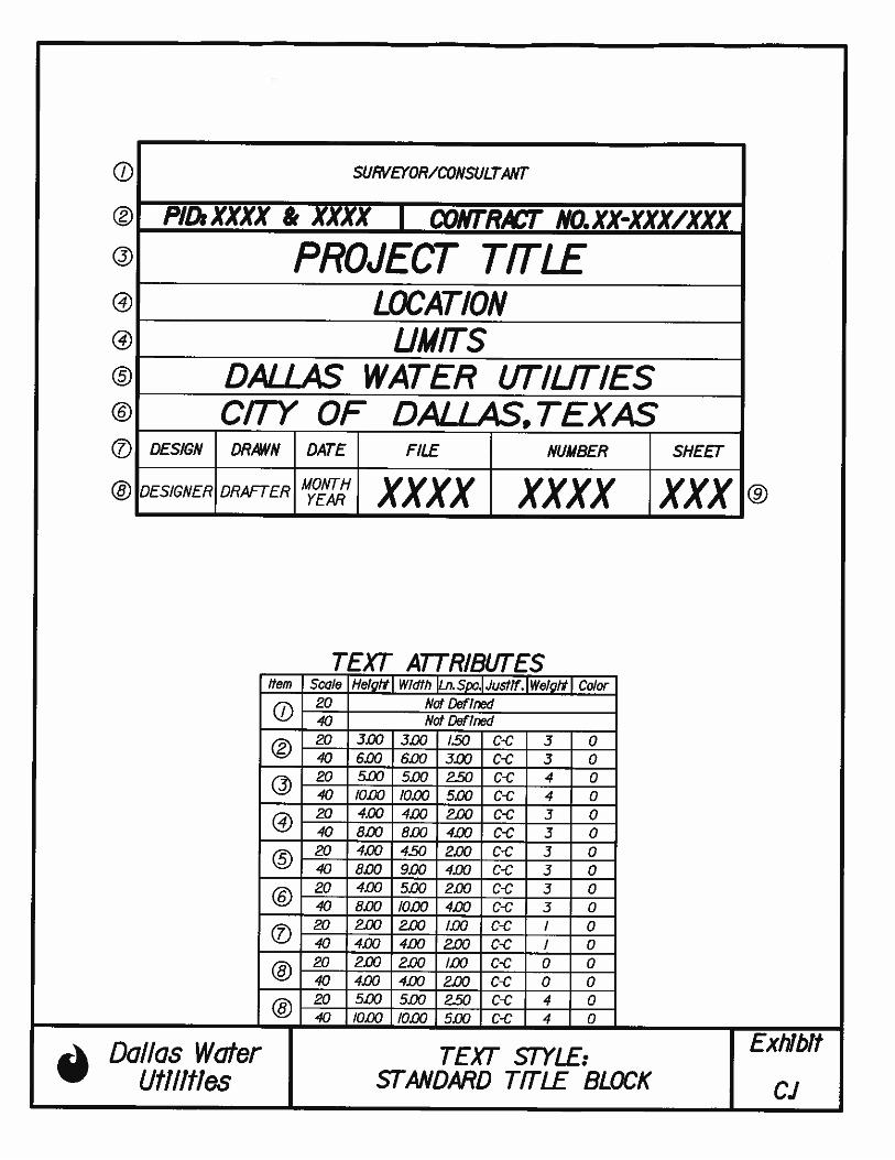
3.5.2 Title Block:
Each sheet shall have a standard title block which shall include an area to conveniently
list the pertinent project reference information as shown FIGURE 3.5.2.
(1) SURVEYOR/CONSULTANT: Firm name(s) of surveyor and design consultant
with registration numbers as applicable
(2) CONTRACT NUMBER: Construction contract number as assigned
(3) PID NUMBERS: Project identification number(s), if applicable
DWU PIPELINE DRAFTING STANDARDS 3-7 OCTOBER 2011
(4) PROJECT TITLE: Size and/or type of the project Example 1: 8” Water Main
Example 2: 12” Water and 8” Wastewater Mains
(5) LOCATION: Location of the projects Example: MAIN ST.
(6) LIMITS: Project limit
Example: FROM PEAL ST. TO ERVAY ST.
(7) DESIGN: First initial and last name of the designer
(8) DRAWN: First initial and last name of the drafter
(9) DATE: Month and Year plan were sealed Example: Jan, 2010
(10) FILE:
File Prefix number as assigned Example: 685W
(11) NUMBER: File Number as assigned
(12) SHEET NUMBER: Sheet number as assigned
FIGURE 3.5.2 STANDARD TITLE BLOCK
DWU PIPELINE DRAFTING STANDARDS 3-8 OCTOBER 2011
3.5.3 Bar Scale:
Each sheet shall have standard horizontal and vertical bar scales for plan and profile as
applicable.
3.5.4 Water/Wastewater References:
All the pertinent water and wastewater as-built map reference numbers shall be
mentioned.
3.5.5 Engineer’s Seal/Disclaimer
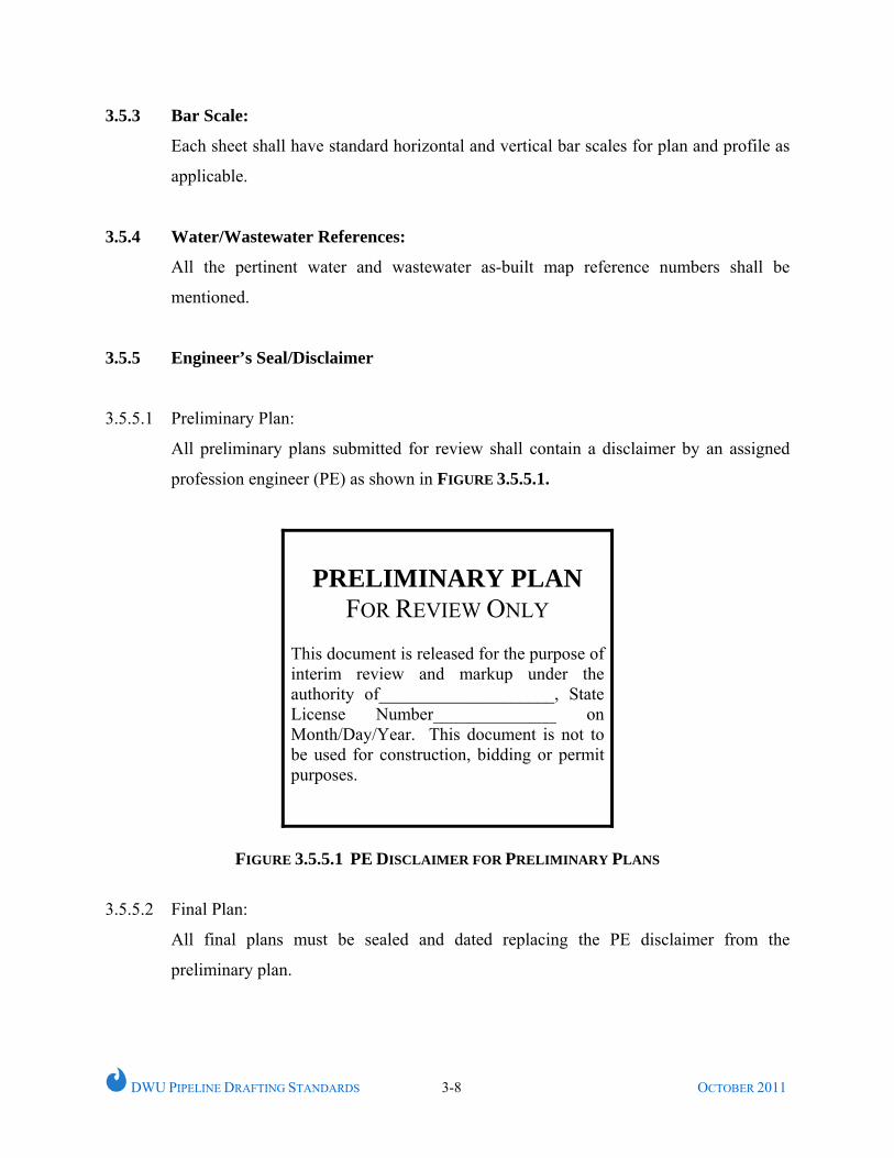
3.5.5.1 Preliminary Plan:
All preliminary plans submitted for review shall contain a disclaimer by an assigned
profession engineer (PE) as shown in FIGURE 3.5.5.1.
PRELIMINARY PLAN
FOR REVIEW ONLY This document is released for the purpose of interim review and markup under the authority of____________________, State License Number______________ on Month/Day/Year. This document is not to be used for construction, bidding or permit purposes.
FIGURE 3.5.5.1 PE DISCLAIMER FOR PRELIMINARY PLANS
3.5.5.2 Final Plan:
All final plans must be sealed and dated replacing the PE disclaimer from the
preliminary plan.
DWU PIPELINE DRAFTING STANDARDS 3-9 OCTOBER 2011
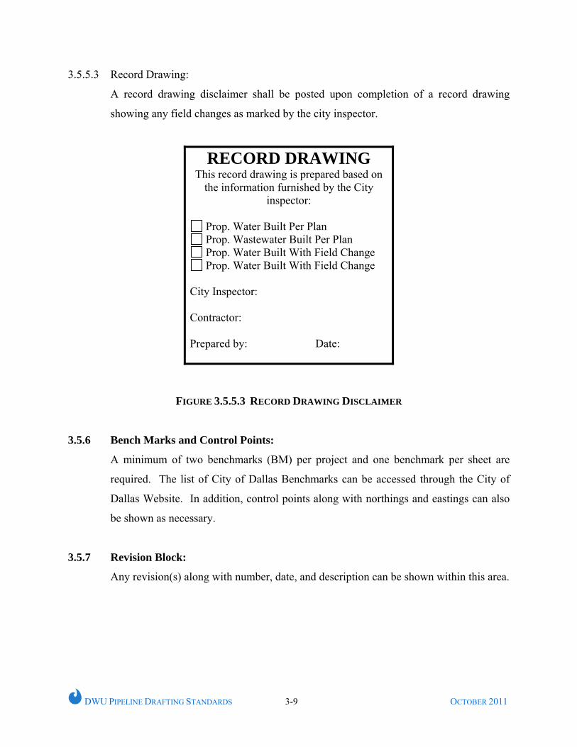
3.5.5.3 Record Drawing:
A record drawing disclaimer shall be posted upon completion of a record drawing
showing any field changes as marked by the city inspector.
RECORD DRAWING This record drawing is prepared based on
the information furnished by the City inspector:
Prop. Water Built Per Plan Prop. Wastewater Built Per Plan Prop. Water Built With Field Change Prop. Water Built With Field Change
City Inspector: Contractor: Prepared by: Date:
FIGURE 3.5.5.3 RECORD DRAWING DISCLAIMER
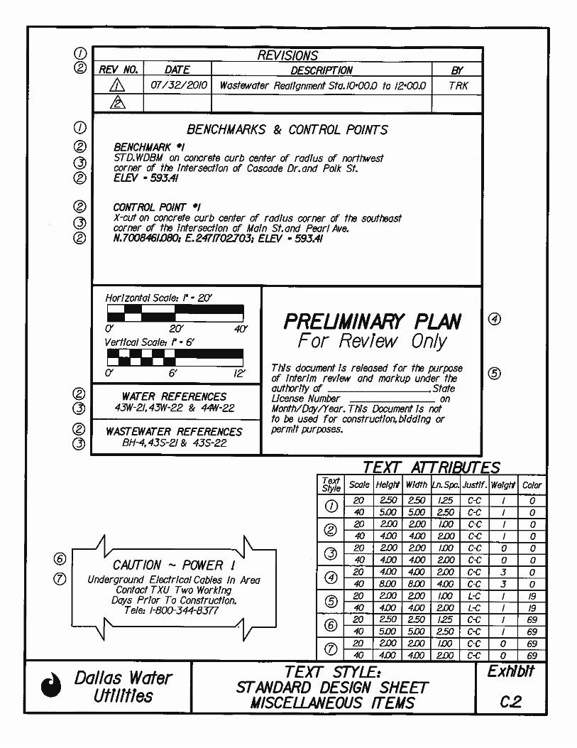
3.5.6 Bench Marks and Control Points:
A minimum of two benchmarks (BM) per project and one benchmark per sheet are
required. The list of City of Dallas Benchmarks can be accessed through the City of
Dallas Website. In addition, control points along with northings and eastings can also
be shown as necessary.
3.5.7 Revision Block:
Any revision(s) along with number, date, and description can be shown within this area.
DWU PIPELINE DRAFTING STANDARDS 3-11 OCTOBER 2011
3.5.8 Caution Notes:
Special caution notes shall be used as necessary. This may include, but not be limited
to, caution notes for underground gas, electrical, telephone, fiber optic, and other
utilities as necessary.
3.5.9 Project Location Map:
Each project shall have a project location map either on the cover sheet or the first sheet
after the cover sheet. Location maps, not placed on cover sheets, shall be positioned at
the upper right hand corner on the first plan view sheet of each project and oriented
with a north arrow pointing to the top of the sheet. It shall be of sufficient detail and
size (3.5” x 5”) to convey the project location in reference to the local thoroughfares.
The project location and its limit are to be identified. It is not necessary to include the
location map on subsequent design sheets within the same project.
3.5.10 North Arrow:
Each design sheet and location map shall have a standard arrow typically pointing up or
to the right.
DWU PIPELINE DRAFTING STANDARDS 3-11 OCTOBER 2011
3.6 STANDARD CALLOUTS
All water and wastewater main callouts shall be in accordance with the standards as
stipulated in this section. Typically, plan callouts shall be listed in order of
construction sequences.
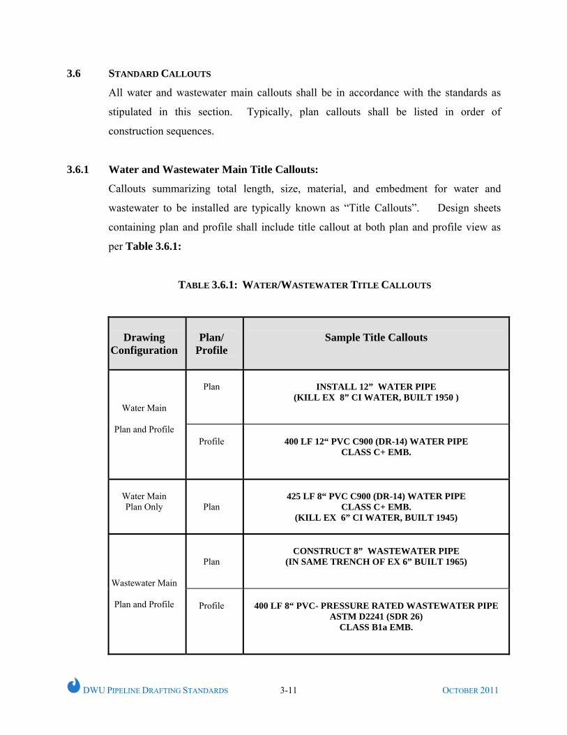
3.6.1 Water and Wastewater Main Title Callouts:
Callouts summarizing total length, size, material, and embedment for water and
wastewater to be installed are typically known as “Title Callouts”. Design sheets
containing plan and profile shall include title callout at both plan and profile view as
per Table 3.6.1:
TABLE 3.6.1: WATER/WASTEWATER TITLE CALLOUTS
Drawing
Configuration
Plan/
Profile
Sample Title Callouts
Plan
INSTALL 12” WATER PIPE
(KILL EX 8” CI WATER, BUILT 1950 )
Water Main
Plan and Profile Profile
400 LF 12“ PVC C900 (DR-14) WATER PIPE
CLASS C+ EMB.
Water Main Plan Only
Plan
425 LF 8“ PVC C900 (DR-14) WATER PIPE
CLASS C+ EMB. (KILL EX 6” CI WATER, BUILT 1945)
Plan
CONSTRUCT 8” WASTEWATER PIPE
(IN SAME TRENCH OF EX 6” BUILT 1965)
Wastewater Main
Plan and Profile
Profile
400 LF 8“ PVC- PRESSURE RATED WASTEWATER PIPE
ASTM D2241 (SDR 26) CLASS B1a EMB.
DWU PIPELINE DRAFTING STANDARDS 3-12 OCTOBER 2011
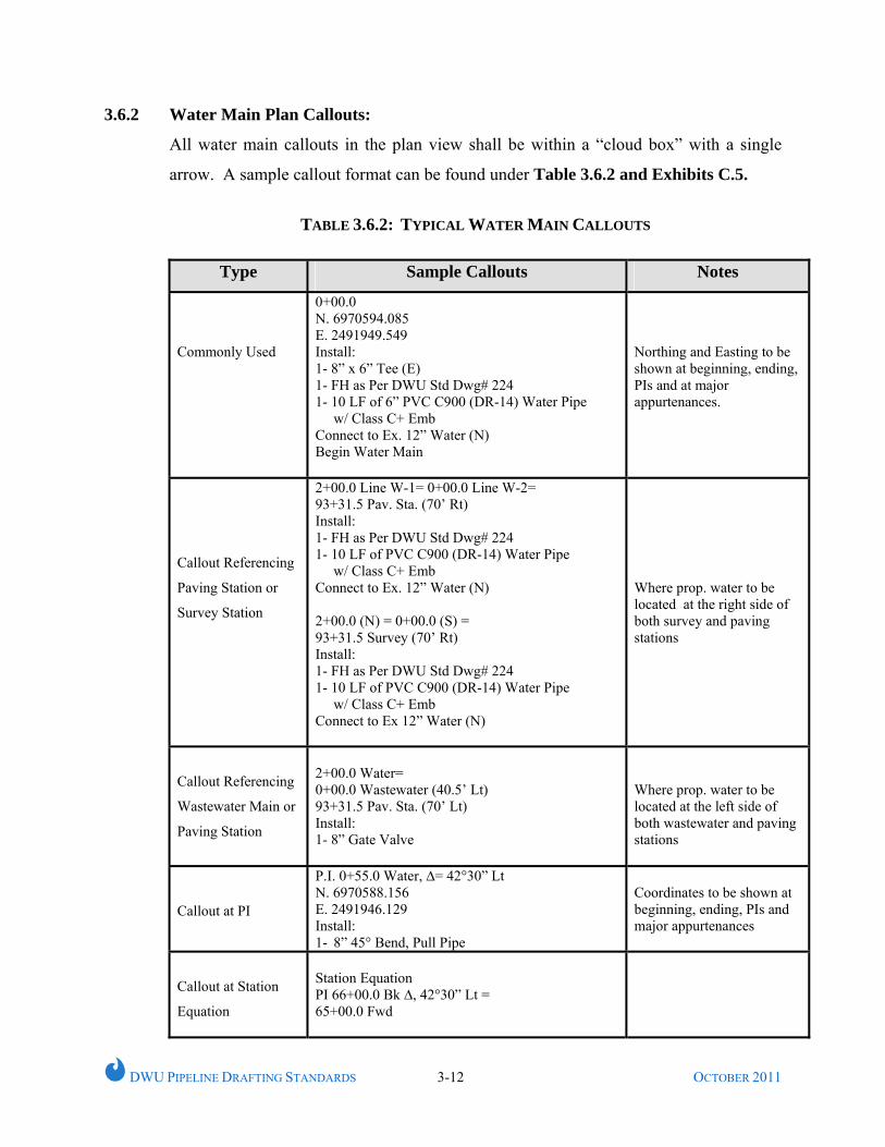
3.6.2 Water Main Plan Callouts:
All water main callouts in the plan view shall be within a “cloud box” with a single
arrow. A sample callout format can be found under Table 3.6.2 and Exhibits C.5.
TABLE 3.6.2: TYPICAL WATER MAIN CALLOUTS
Type Sample Callouts Notes
Commonly Used
0+00.0 N. 6970594.085 E. 2491949.549 Install: 1- 8” x 6” Tee (E) 1- FH as Per DWU Std Dwg# 224 1- 10 LF of 6” PVC C900 (DR-14) Water Pipe w/ Class C+ Emb Connect to Ex. 12” Water (N) Begin Water Main
Northing and Easting to be shown at beginning, ending, PIs and at major appurtenances.
Callout Referencing
Paving Station or
Survey Station
2+00.0 Line W-1= 0+00.0 Line W-2= 93+31.5 Pav. Sta. (70’ Rt) Install: 1- FH as Per DWU Std Dwg# 224 1- 10 LF of PVC C900 (DR-14) Water Pipe w/ Class C+ Emb Connect to Ex. 12” Water (N) 2+00.0 (N) = 0+00.0 (S) = 93+31.5 Survey (70’ Rt) Install: 1- FH as Per DWU Std Dwg# 224 1- 10 LF of PVC C900 (DR-14) Water Pipe w/ Class C+ Emb Connect to Ex 12” Water (N)
Where prop. water to be located at the right side of both survey and paving stations
Callout Referencing
Wastewater Main or
Paving Station
2+00.0 Water= 0+00.0 Wastewater (40.5’ Lt) 93+31.5 Pav. Sta. (70’ Lt) Install: 1- 8” Gate Valve
Where prop. water to be located at the left side of both wastewater and paving stations
Callout at PI
P.I. 0+55.0 Water, ∆= 42°30” Lt N. 6970588.156 E. 2491946.129 Install: 1- 8” 45° Bend, Pull Pipe
Coordinates to be shown at beginning, ending, PIs and major appurtenances
Callout at Station
Equation
Station Equation PI 66+00.0 Bk ∆, 42°30” Lt = 65+00.0 Fwd
DWU PIPELINE DRAFTING STANDARDS 3-13 OCTOBER 2011
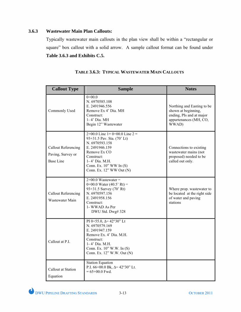
3.6.3 Wastewater Main Plan Callouts:
Typically wastewater main callouts in the plan view shall be within a “rectangular or
square” box callout with a solid arrow. A sample callout format can be found under
Table 3.6.3 and Exhibits C.5.
TABLE 3.6.3: TYPICAL WASTEWATER MAIN CALLOUTS
Callout Type Sample Notes
Commonly Used
0+00.0 N. 6970585.108 E. 2491946.556 Remove Ex 4’ Dia. MH Construct: 1- 4’ Dia. MH Begin 12” Wastewater
Northing and Easting to be shown at beginning, ending, PIs and at major appurtenances (MH, CO, WWAD)
Callout Referencing
Paving, Survey or
Base Line
2+00.0 Line 1= 0+00.0 Line 2 = 93+31.5 Pav. Sta. (70’ Lt) N. 6970593.158 E. 2491946.159 Remove Ex CO Construct: 1- 4’ Dia. M.H. Conn. Ex. 10” WW In (S) Conn. Ex. 12” WW Out (N)
Connections to existing wastewater mains (not proposed) needed to be called out only.
Callout Referencing
Wastewater Main
2+00.0 Wastewater = 0+00.0 Water (40.5’ Rt) = 93+31.5 Survey (70’ Rt) N. 6970597.156 E. 2491958.156 Construct: 1- WWAD As Per DWU Std. Dwg# 328
Where prop. wastewater to be located at the right side of water and paving stations
Callout at P.I.
PI 0+55.0, ∆= 42°30” Lt N. 6970579.169 E. 2491947.159 Remove Ex. 4’ Dia. M.H. Construct: 1- 4’ Dia. M.H. Conn. Ex. 10” W.W. In (S) Conn. Ex. 12” W.W. Out (N)
Callout at Station
Equation
Station Equation P.I. 66+00.0 Bk, ∆= 42°30” Lt. = 65+00.0 Fwd.
DWU PIPELINE DRAFTING STANDARDS 4-1 OCTOBER 2011
CHAPTER 4
WORKING UNITS, COLOR, STYLE AND WEIGHT
4.1 GENERAL
This chapter addresses various computer aided drafting and design (CADD) elements,
settings and attributes as applicable to DWU water and wastewater main design in
MicroStation DGN file format.
4.2 WORKING UNITS
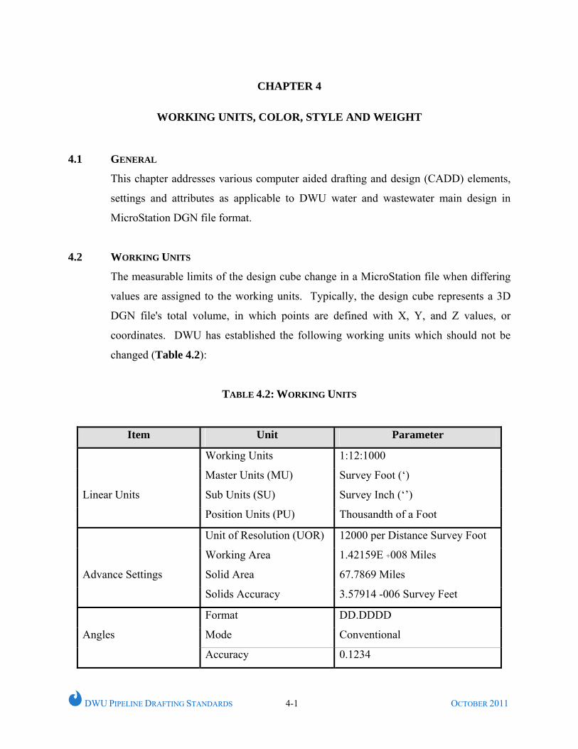
The measurable limits of the design cube change in a MicroStation file when differing
values are assigned to the working units. Typically, the design cube represents a 3D
DGN file's total volume, in which points are defined with X, Y, and Z values, or
coordinates. DWU has established the following working units which should not be
changed (Table 4.2):
TABLE 4.2: WORKING UNITS
Item Unit Parameter
Working Units 1:12:1000
Master Units (MU) Survey Foot (‘)
Sub Units (SU) Survey Inch (‘’)
Linear Units
Position Units (PU) Thousandth of a Foot
Unit of Resolution (UOR) 12000 per Distance Survey Foot
Working Area 1.42159E +008 Miles
Solid Area 67.7869 Miles
Advance Settings
Solids Accuracy 3.57914 -006 Survey Feet
Format DD.DDDD
Mode Conventional
Angles
Accuracy 0.1234
DWU PIPELINE DRAFTING STANDARDS 4-2 OCTOBER 2011
4.3 GLOBAL ORIGIN (GO)
The default Global Origin (GO) for a 2D file in MicroStation is set to the center of the
design plane with coordinate values of 0, 0. Since the design plane functions like the
Cartesian coordinates system, all coordinates left of or below the default global origin
are negative and all coordinates to the right or above are positive.
Global Origin for DWU Mapping System:
2D: 0, 0
3D: 0, 0, 0
4.4 COLOR
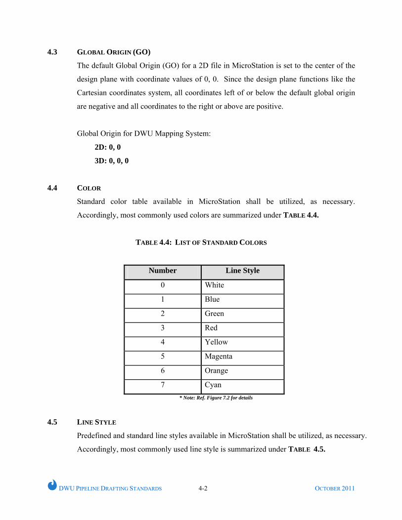
Standard color table available in MicroStation shall be utilized, as necessary.
Accordingly, most commonly used colors are summarized under TABLE 4.4.
TABLE 4.4: LIST OF STANDARD COLORS
Number Line Style
0 White
1 Blue
2 Green
3 Red
4 Yellow
5 Magenta
6 Orange
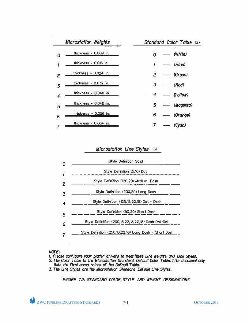
7 Cyan * Note: Ref. Figure 7.2 for details
4.5 LINE STYLE
Predefined and standard line styles available in MicroStation shall be utilized, as necessary.
Accordingly, most commonly used line style is summarized under TABLE 4.5.
DWU PIPELINE DRAFTING STANDARDS 4-3 OCTOBER 2011
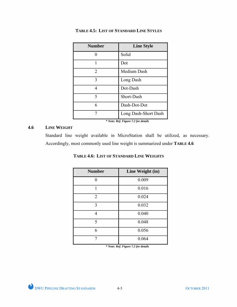
TABLE 4.5: LIST OF STANDARD LINE STYLES
Number Line Style
0 Solid
1 Dot
2 Medium Dash
3 Long Dash
4 Dot-Dash
5 Short-Dash
6 Dash-Dot-Dot
7 Long Dash-Short Dash * Note: Ref. Figure 7.2 for details
4.6 LINE WEIGHT
Standard line weight available in MicroStation shall be utilized, as necessary.
Accordingly, most commonly used line weight is summarized under TABLE 4.6
TABLE 4.6: LIST OF STANDARD LINE WEIGHTS
* Note: Ref. Figure 7.2 for details
Number Line Weight (in)
0 0.009
1 0.016
2 0.024
3 0.032
4 0.040
5 0.048
6 0.056
7 0.064
DWU PIPELINE DRAFTING STANDARDS 5-1 OCTOBER 2011
CHAPTER 5
LEVEL MANAGEMENT
5.1 GENERAL
This Chapter discusses standard levels along with predefined attributes, consisting of
specific colors, line styles, and line weights to be used for any project.
5.2 LEVEL NAMING CONVENTION
A typical MicroStation level shall be named as:
“Major Category_Sub Category_Item Name_Feature Description
Where, “Major Category” is the abbreviation for General (G), Civil (C), Architectural
(A), Mechanical (M), Electrical (E), Surveying (V) or other major categories.
Accordingly, a typical example of a predefined level can be shown as follows:
V_PROPERTY_ BLOCK_NUM
V_PROPERTY_LOT_LINE
DWU PIPELINE DRAFTING STANDARDS 5-2 OCTOBER 2011
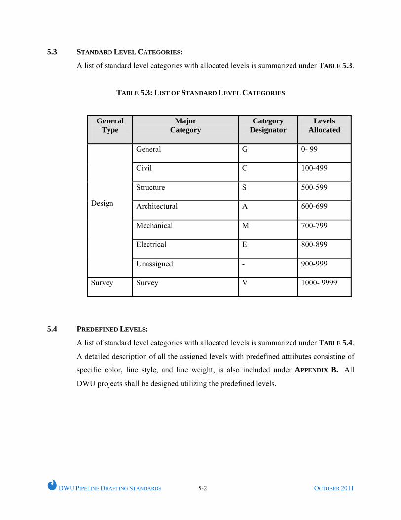
5.3 STANDARD LEVEL CATEGORIES:
A list of standard level categories with allocated levels is summarized under TABLE 5.3.
TABLE 5.3: LIST OF STANDARD LEVEL CATEGORIES
General Type
Major Category
Category Designator
Levels Allocated
General G
0- 99
Civil
C 100-499
Structure
S 500-599
Architectural
A 600-699
Mechanical
M 700-799
Electrical
E 800-899
Design
Unassigned
- 900-999
Survey Survey V
1000- 9999
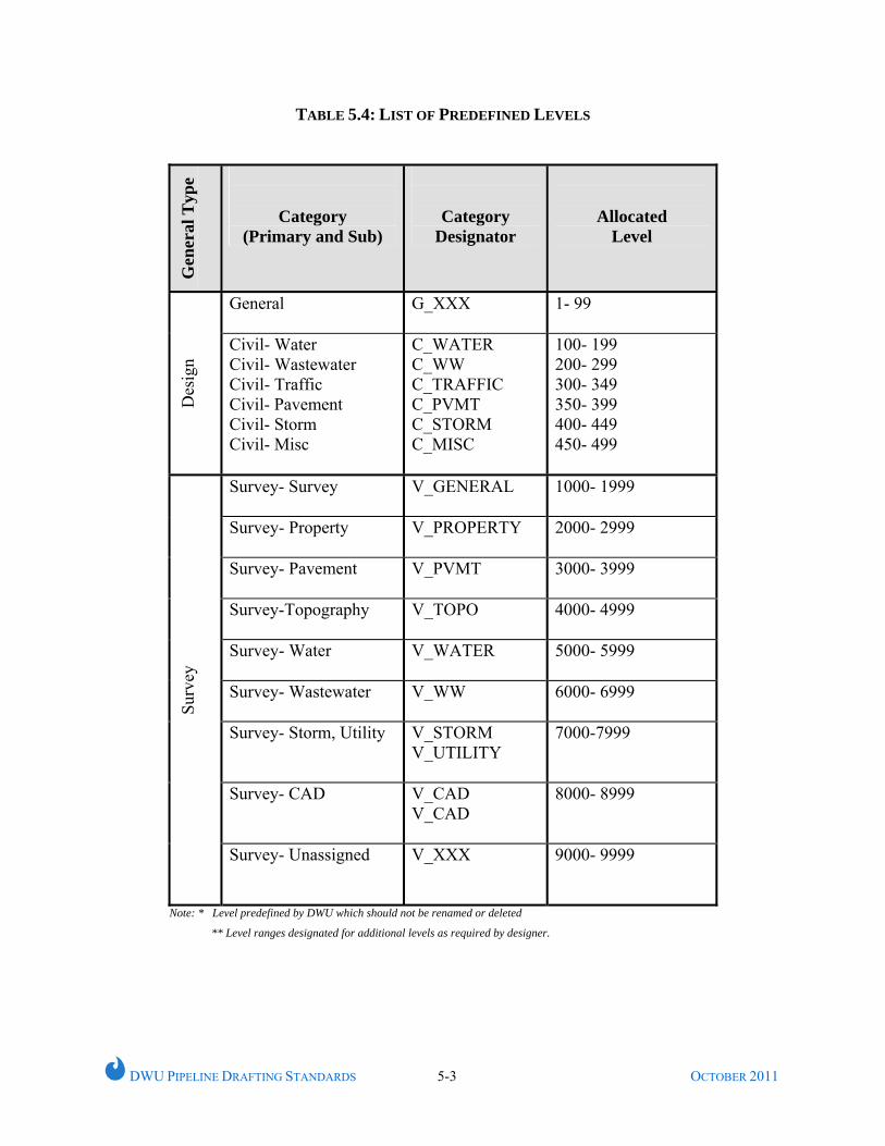
5.4 PREDEFINED LEVELS:
A list of standard level categories with allocated levels is summarized under TABLE 5.4.
A detailed description of all the assigned levels with predefined attributes consisting of
specific color, line style, and line weight, is also included under APPENDIX B. All
DWU projects shall be designed utilizing the predefined levels.
DWU PIPELINE DRAFTING STANDARDS 5-3 OCTOBER 2011
TABLE 5.4: LIST OF PREDEFINED LEVELS
Gen
eral
Typ
e
Category (Primary and Sub)
Category Designator
Allocated Level
General G_XXX
1- 99
Des
ign
Civil- Water Civil- Wastewater Civil- Traffic Civil- Pavement Civil- Storm Civil- Misc
C_WATER C_WW C_TRAFFIC C_PVMT C_STORM C_MISC
100- 199 200- 299 300- 349 350- 399 400- 449 450- 499
Survey- Survey
V_GENERAL
1000- 1999
Survey- Property
V_PROPERTY
2000- 2999
Survey- Pavement
V_PVMT 3000- 3999
Survey-Topography V_TOPO
4000- 4999
Survey- Water
V_WATER 5000- 5999
Survey- Wastewater
V_WW
6000- 6999
Survey- Storm, Utility
V_STORM V_UTILITY
7000-7999
Survey- CAD
V_CAD V_CAD
8000- 8999
Surv
ey
Survey- Unassigned
V_XXX
9000- 9999
Note: * Level predefined by DWU which should not be renamed or deleted
** Level ranges designated for additional levels as required by designer.
DWU PIPELINE DRAFTING STANDARDS 6-1 OCTOBER 2011
CHAPTER 6
DRAFTING RESOURCE LIBRARIES
6.1 GENERAL
This chapter addresses various parameters of standard DWU seed files and project
interface drawings to be used for water and wastewater main design in MicroStation
format.
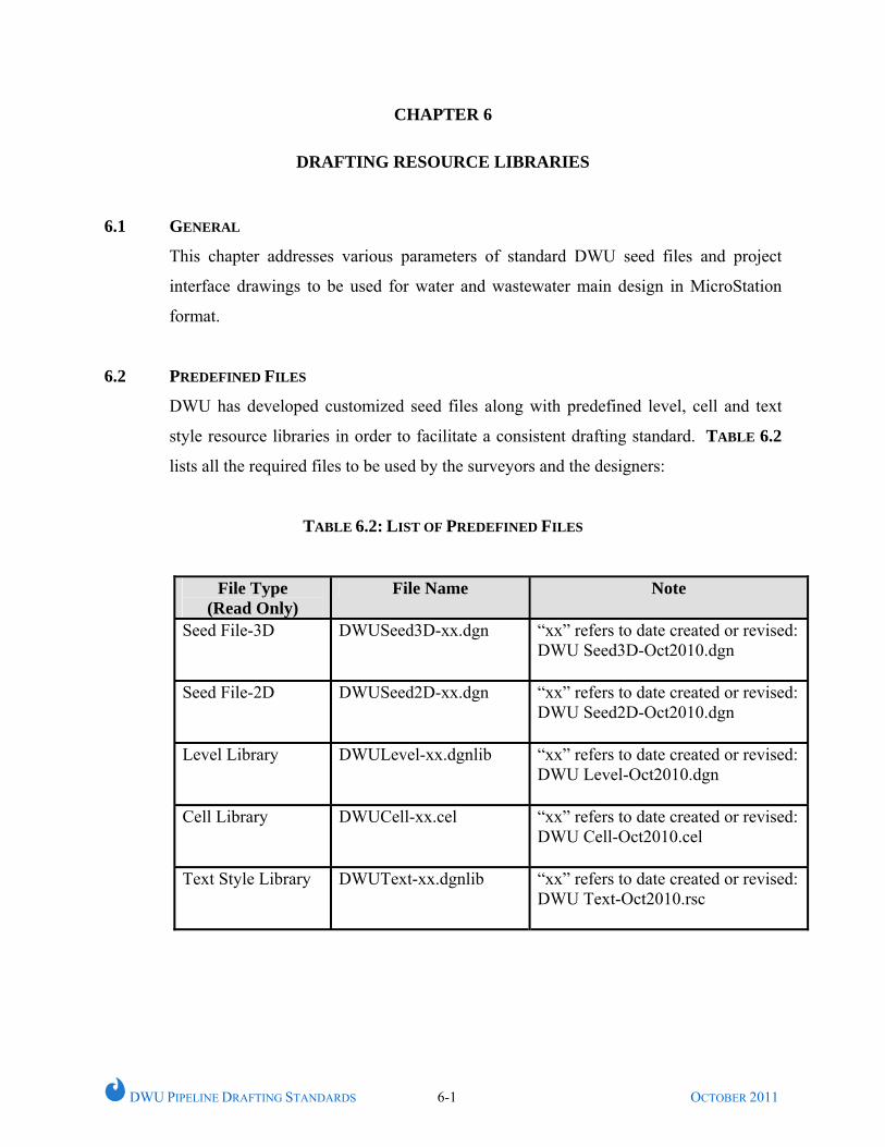
6.2 PREDEFINED FILES
DWU has developed customized seed files along with predefined level, cell and text
style resource libraries in order to facilitate a consistent drafting standard. TABLE 6.2
lists all the required files to be used by the surveyors and the designers:
TABLE 6.2: LIST OF PREDEFINED FILES
File Type (Read Only)
File Name Note
Seed File-3D
DWUSeed3D-xx.dgn “xx” refers to date created or revised: DWU Seed3D-Oct2010.dgn
Seed File-2D
DWUSeed2D-xx.dgn “xx” refers to date created or revised: DWU Seed2D-Oct2010.dgn
Level Library
DWULevel-xx.dgnlib “xx” refers to date created or revised: DWU Level-Oct2010.dgn
Cell Library
DWUCell-xx.cel “xx” refers to date created or revised: DWU Cell-Oct2010.cel
Text Style Library
DWUText-xx.dgnlib “xx” refers to date created or revised: DWU Text-Oct2010.rsc
DWU PIPELINE DRAFTING STANDARDS 6-2 OCTOBER 2011
6.3 SEED FILE
MicroStation based 2D and 3D seed files have been developed by DWU Engineering
Services to incorporate various elements of the DWU drafting standards. These files
can be obtained from City of Dallas or DWU website.
6.4 LEVEL LIBRARY
DWU standard seed file with predefined levels will assist the CAD user to place design
elements with the correct color, style and weight. These levels have been divided into
major categories and can be manipulated by using a set of filters:
• Survey General Items
• Ex. Water
• Ex. Wastewater
• Prop. Water
• Prop. Wastewater
• Used Levels
6.5 CELL LIBRARY
The DWU cell library consists of standard symbols conform to DWU standards. Most
cells are developed with predefined attributes consisting of specific color, style, and
weight.
6.6 TEXT STYLE RESOURCE LIBRARY
A text resource library consisting of predefined text attributes has been developed in
accordance with DWU standards. This text style library shall be loaded within the
DWU standard seed files. A list of various text styles and standards of annotation are
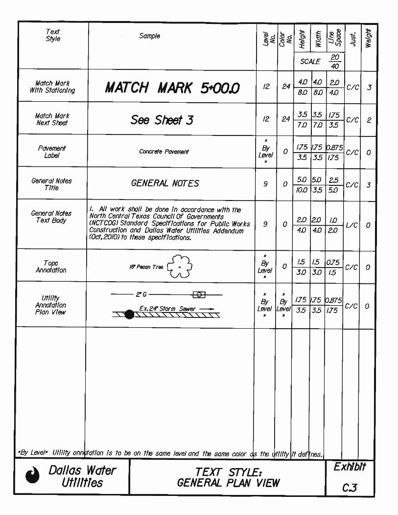
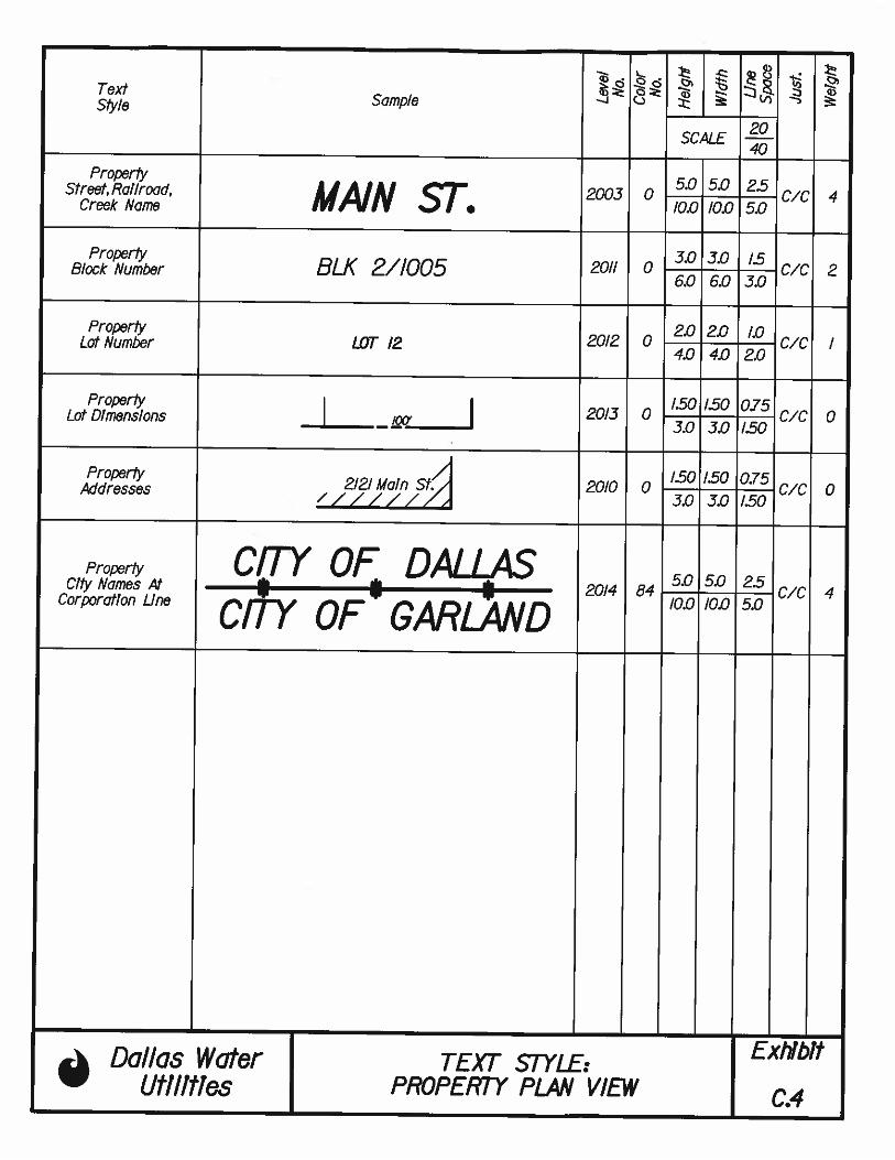
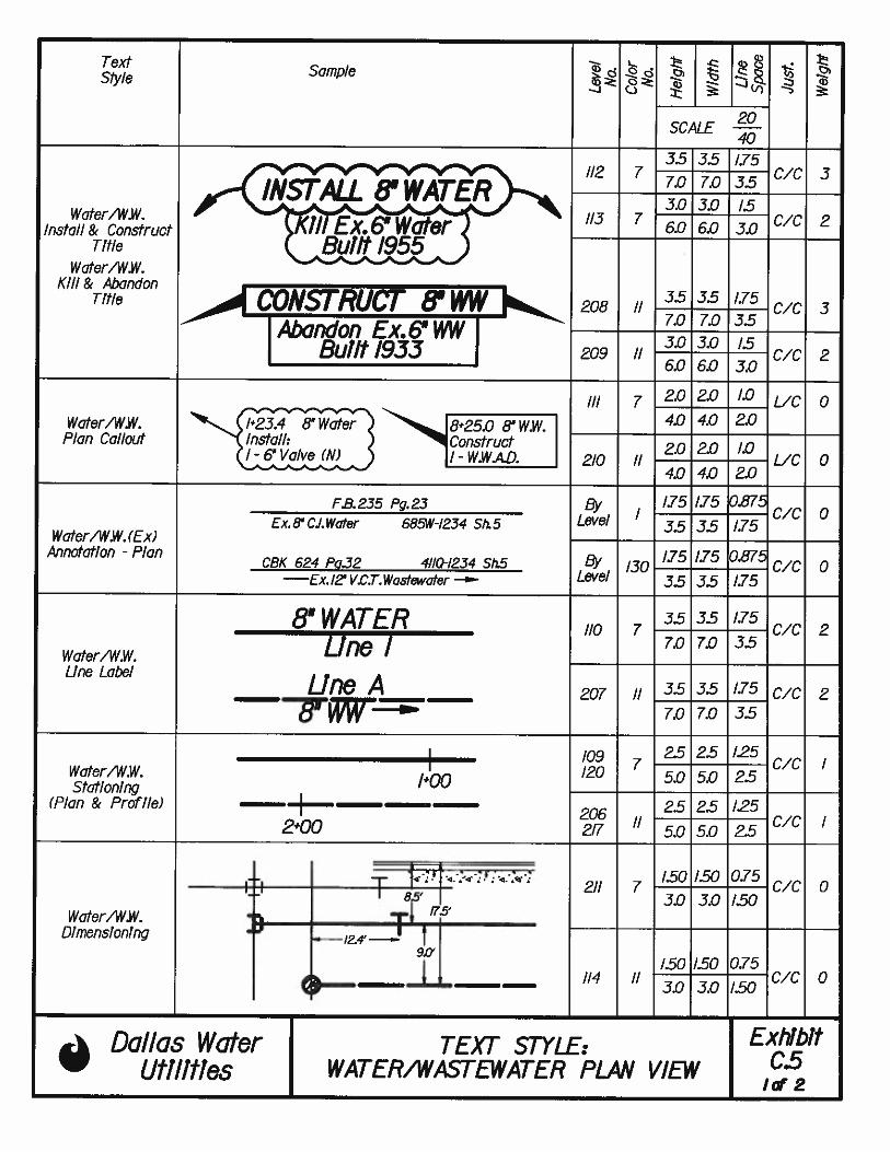
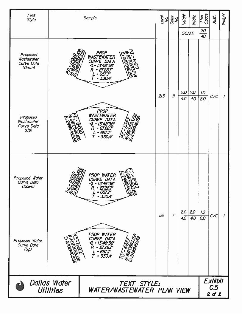
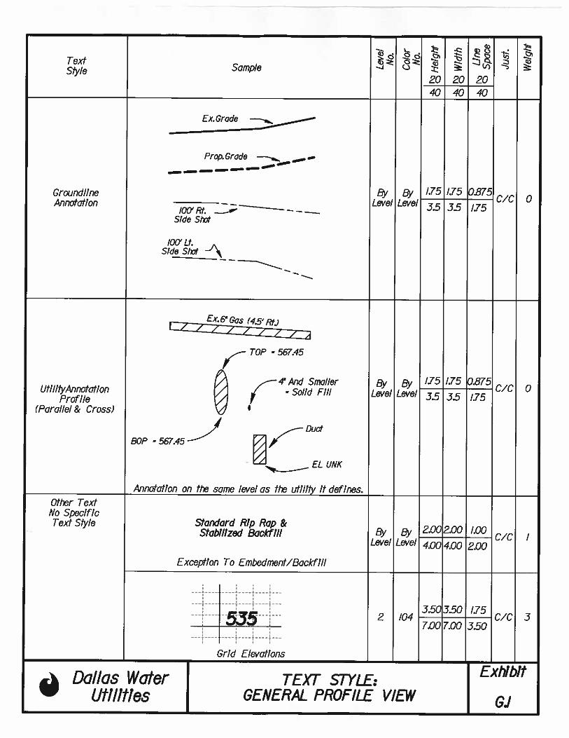
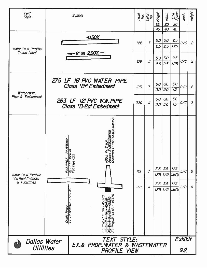
shown under EXHIBITS C.1- C.5, G.1- G.2, I-5 and J-3.
DWU PIPELINE DRAFTING STANDARDS 6-3 OCTOBER 2011
6.7 MISCELLANEOUS DRAWING FEATURES
All drawings consisting of existing and proposed features shall be prepared in
accordance with the DWU Standards:
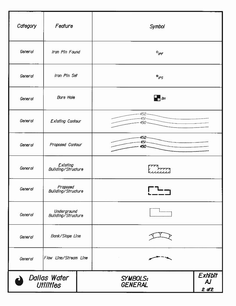
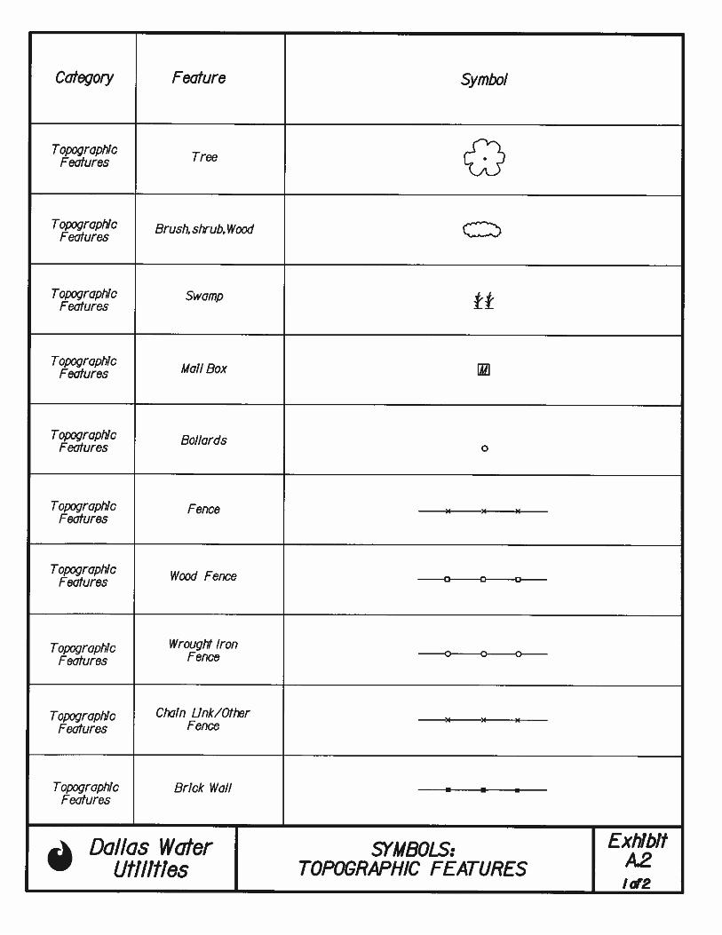
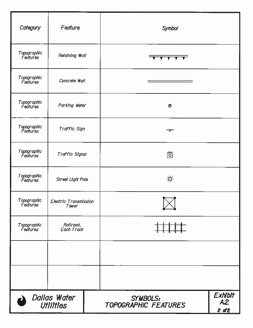
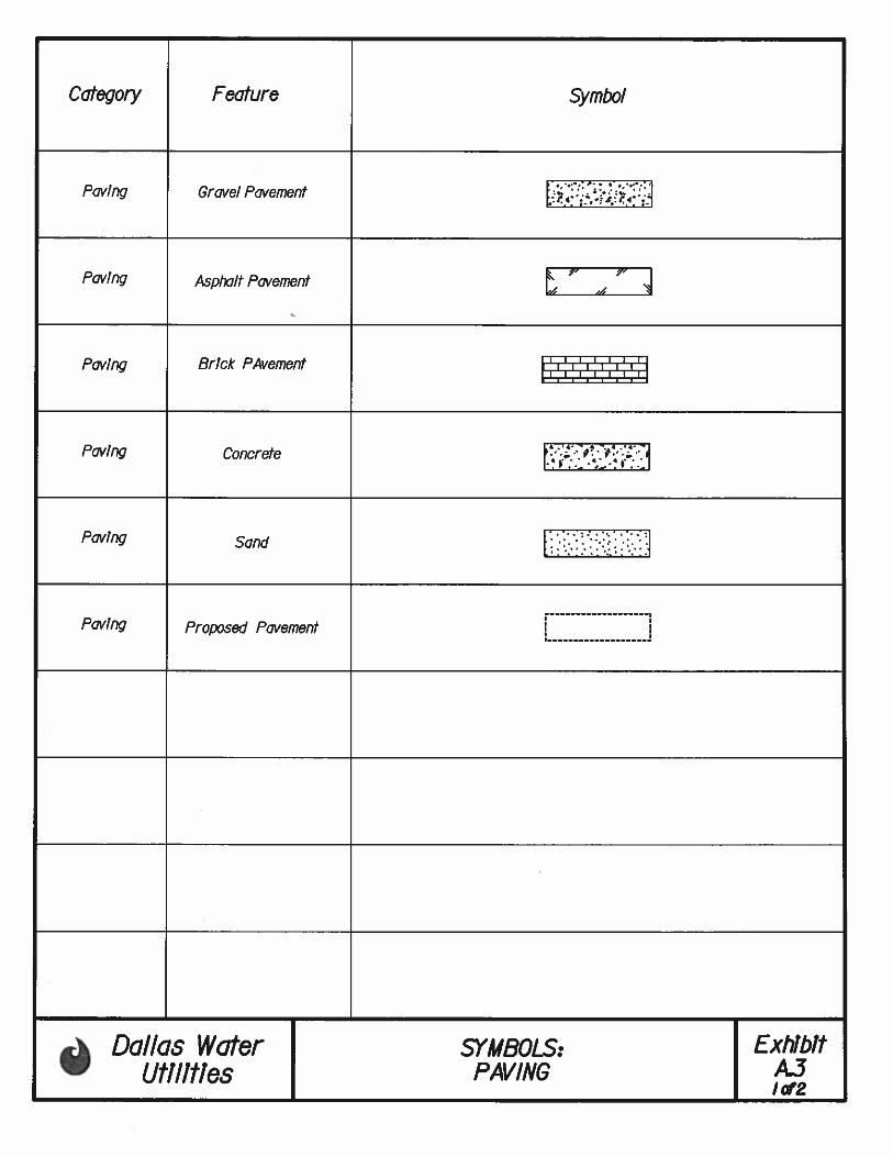
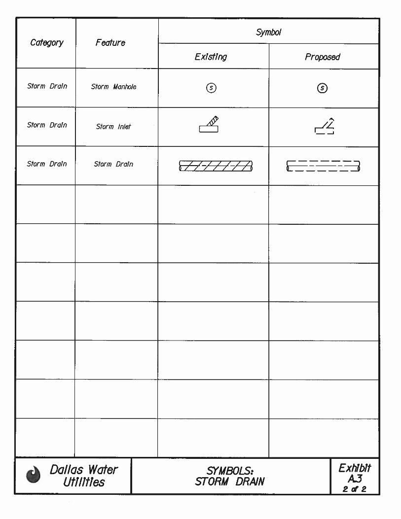
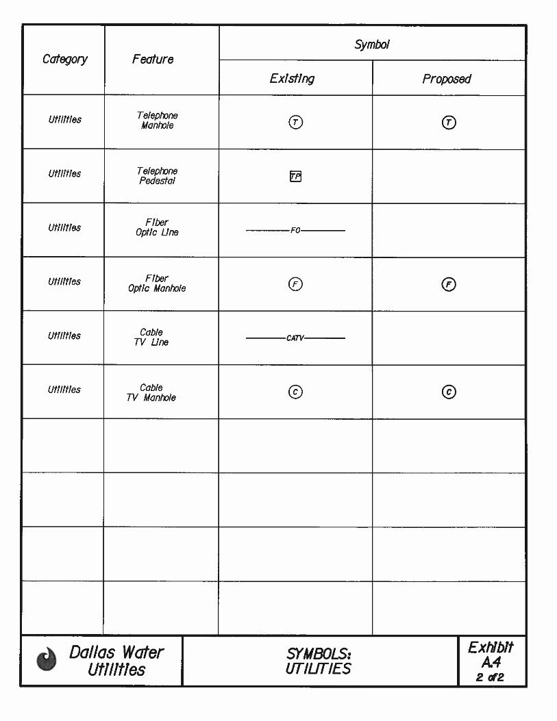
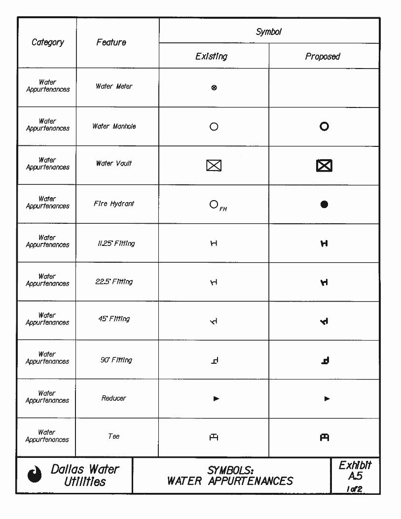
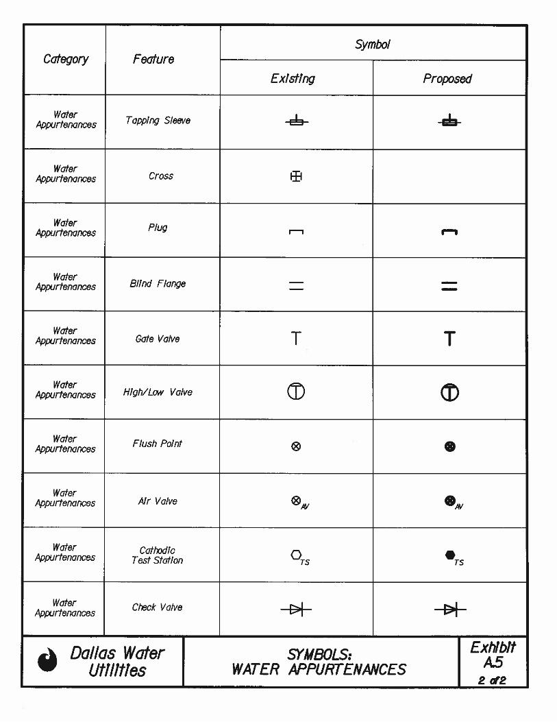
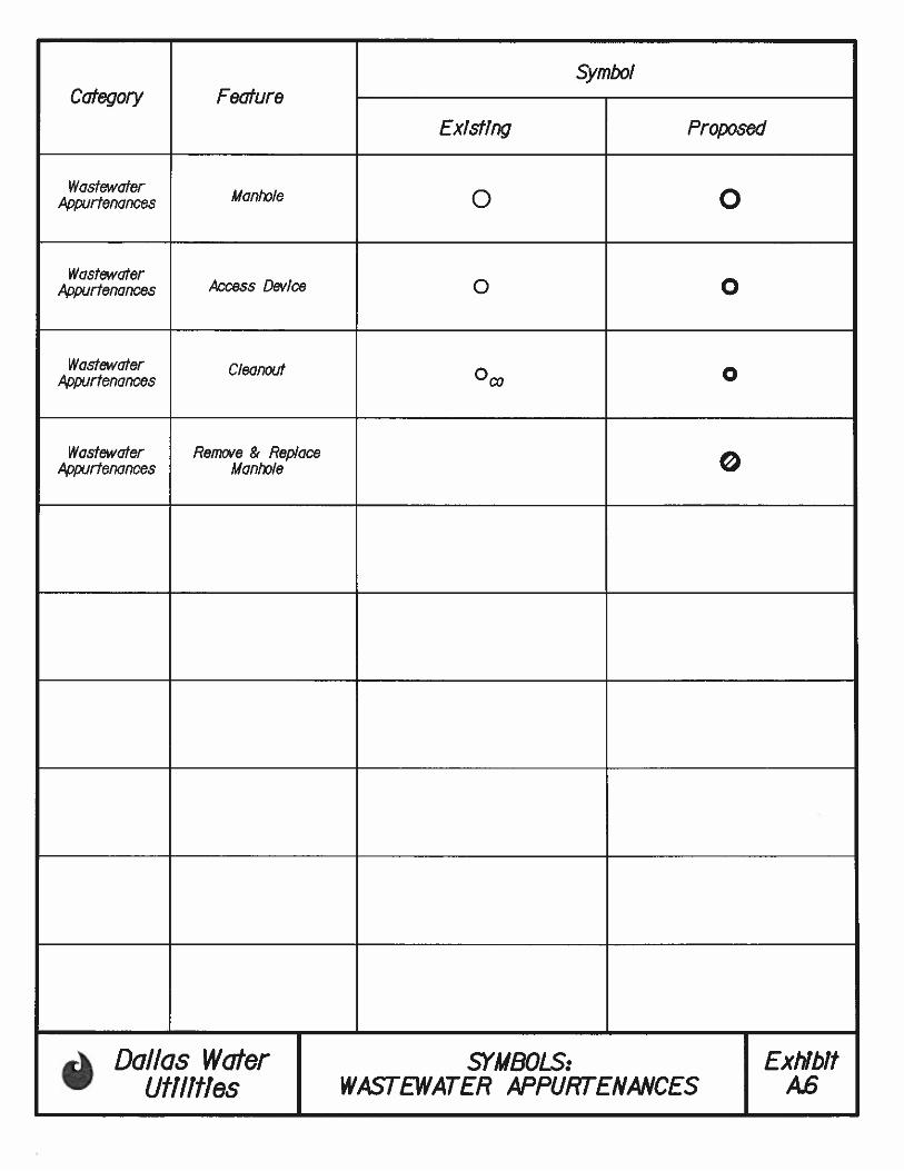
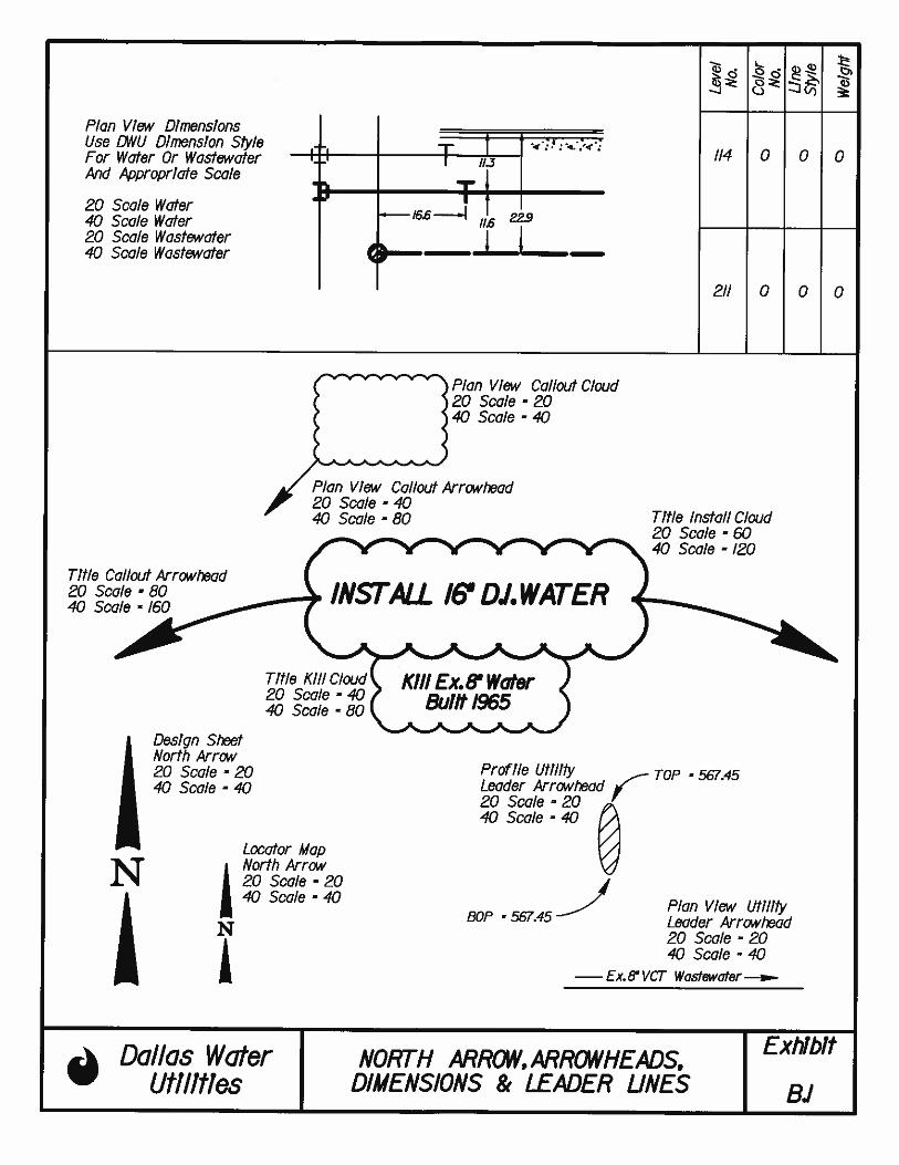
6.7.1 Standard Symbols:
A list of standard symbols is included under EXHIBITS A.1- A.6. In addition, standard
arrowheads are shown in EXHIBITS B.1.
6.7.2 Plan View: Property, Pavement and Utilities
Plan view of various existing and proposed property, pavement, storm drains, utilities,
and water and wastewater features are demonstrated under following EXHIBITS D.1-
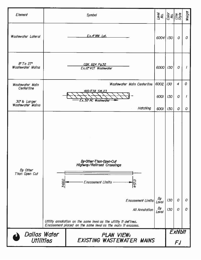
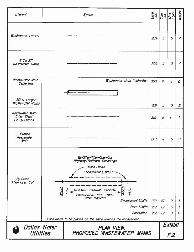
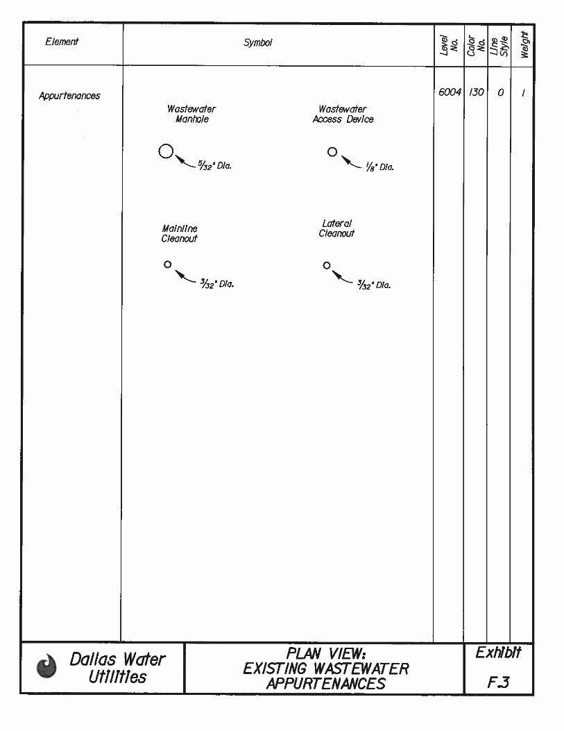
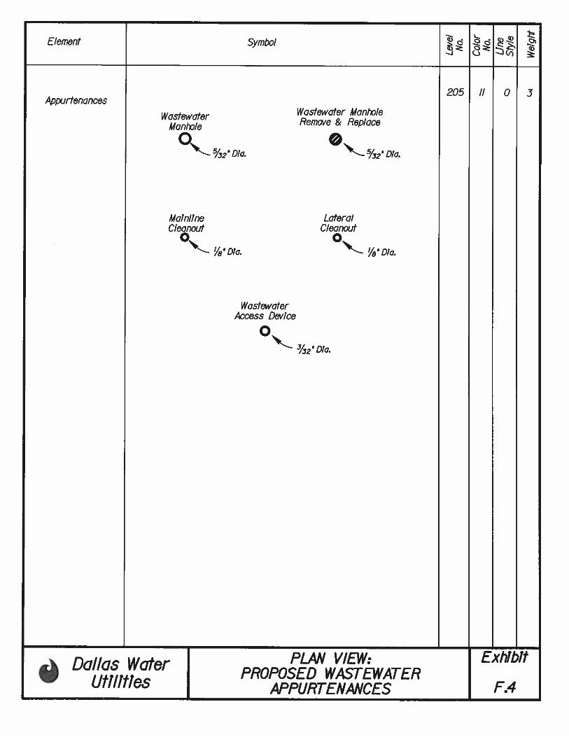
D.4, E.1- E4 and F.1- F.4
6.7.3 Profile View: Property, Pavement and Utilities
Plan view of various existing and proposed property, pavement, storm drains, utilities,
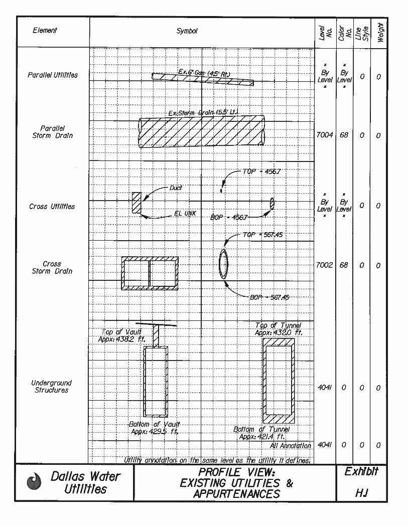
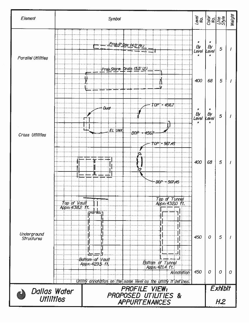
and water/wastewater features are demonstrated under following EXHIBITS H.1- H.2,
I.1- I.5 and J.1- J.3.
6.8 REFERENCE SCHEMATICS
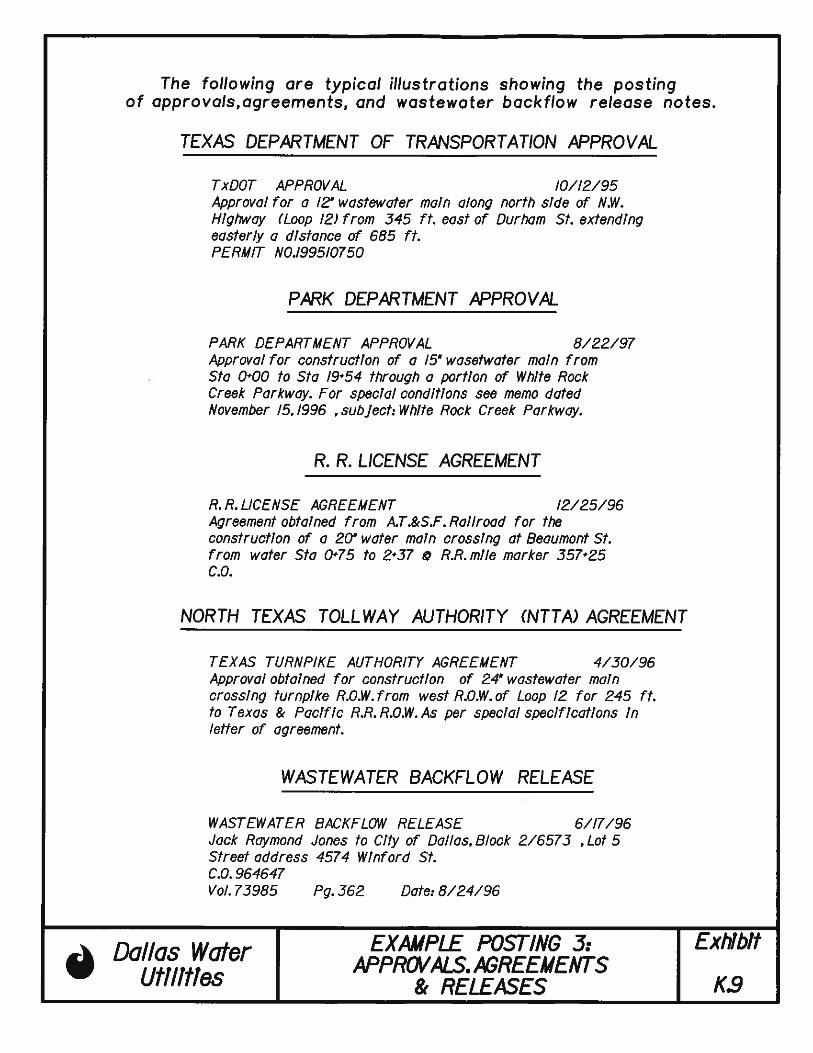
Several example schematic are included under EXHIBITS K.1- K.9.
DWU PIPELINE DRAFTING STANDARDS 7-1 OCTOBER 2011
CHAPTER 7
PLOT CONFIGURATION
7.1 GENERAL
This chapter addresses plot configuration for DWU water and wastewater main design
in MicroStation DGN file format.
7.2 ATTRIBUTE DEFINITIONS
MicroStation files are to be developed at 1:1 “full scale” and then set to the appropriate
1”= 40’ or 1”= 20’ scale when plotting. However, it is imperative to establish the plot
scale of the MicroStation file prior to any placement of text or cells. Font size and
active scale settings for cells will dictate their appearance when plotted to the desired
final drawing scale.
FIGURE 7.2 depicts lines attributes as per Hewlett Packard Graphics Language
(HPGL2) format. This information shall be used in setting up consisting printing
output as necessary.
DWU PIPELINE DRAFTING STANDARDS 7-1 OCTOBER 2011

DWU PIPELINE DRAFTING STANDARDS 7-2 OCTOBER 2011
EXHIBITS

DWU PIPELINE DRAFTING STANDARDS OCTOBER 2011
APPENDICES
DWU PIPELINE DRAFTING STANDARDS OCTOBER 2011
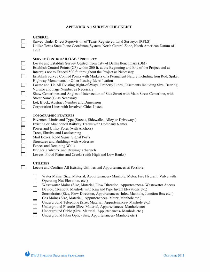
APPENDIX A.1 SURVEY CHECKLIST
GENERAL Survey Under Direct Supervision of Texas Registered Land Surveyor (RPLS) Utilize Texas State Plane Coordinate System, North Central Zone, North American Datum of
1983 SURVEY CONTROL/ R.O.W. / PROPERTY
Locate and Establish Survey Control from City of Dallas Benchmark (BM) Establish Control Points (CP) within 200 ft. at the Beginning and End of the Project and at
Intervals not to Exceed 500 ft. throughout the Project as Necessary Establish Survey Control Points with Markers of a Permanent Nature including Iron Rod, Spike,
Highway Monuments or Other Lasting Identification Locate and Tie All Existing Right-of-Ways, Property Lines, Easements Including Size, Bearing,
Volume and Page Number as Necessary Show Centerlines and Angles of Intersection of Side Street with Main Street Centerline, with
Street Name(s), as Necessary Lot, Block, Abstract Number and Dimension Corporation Lines with Involved Cities Listed
TOPOGRAPHIC FEATURES
Pavement Limits and Type (Streets, Sidewalks, Alley or Driveways) Existing or Abandoned Railway Tracks with Company Names Power and Utility Poles (with Anchors) Trees, Shrubs, and Landscaping Mail Boxes, Road Signs, Signal Posts Structures and Buildings with Addresses Fences and Retaining Walls Bridges, Culverts, and Drainage Channels Levees, Flood Plains and Creeks (with High and Low Banks)
UTILITIES
Locate and Confirm All Existing Utilities and Appurtenances as Possible:
Water Mains (Size, Material, Appurtenances- Manhole, Meter, Fire Hydrant, Valve with Operating Nut Elevation, etc.)
Wastewater Mains (Size, Material, Flow Direction, Appurtenances- Wastewater Access Device, Cleanout, Manhole with Rim and Pipe Invert Elevations etc.)
Stormdrains (Size, Flow Direction, Appurtenances- Inlet, Manhole, Junction Box etc. ) Gas Mains (Size, Material, Appurtenances- Meter, Manhole etc.) Underground Telephone (Size, Material, Appurtenances- Manhole etc.) Underground Electric (Size, Material, Appurtenances- Manhole etc) Underground Cable (Size, Material, Appurtenances- Manhole etc.) Underground Fiber Optic (Size, Appurtenances- Manhole etc.)
DWU PIPELINE DRAFTING STANDARDS OCTOBER 2011
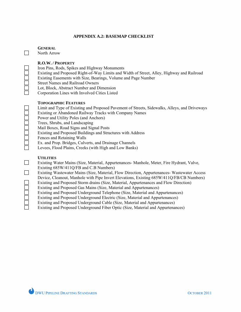
APPENDIX A.2: BASEMAP CHECKLIST
GENERAL
North Arrow R.O.W. / PROPERTY
Iron Pins, Rods, Spikes and Highway Monuments Existing and Proposed Right-of-Way Limits and Width of Street, Alley, Highway and Railroad Existing Easements with Size, Bearings, Volume and Page Number Street Names and Railroad Owners Lot, Block, Abstract Number and Dimension Corporation Lines with Involved Cities Listed
TOPOGRAPHIC FEATURES
Limit and Type of Existing and Proposed Pavement of Streets, Sidewalks, Alleys, and Driveways Existing or Abandoned Railway Tracks with Company Names Power and Utility Poles (and Anchors) Trees, Shrubs, and Landscaping Mail Boxes, Road Signs and Signal Posts Existing and Proposed Buildings and Structures with Address Fences and Retaining Walls Ex. and Prop. Bridges, Culverts, and Drainage Channels Levees, Flood Plains, Creeks (with High and Low Banks)
UTILITIES
Existing Water Mains (Size, Material, Appurtenances- Manhole, Meter, Fire Hydrant, Valve, Existing 685W/411Q/FB and C.B Numbers)
Existing Wastewater Mains (Size, Material, Flow Direction, Appurtenances- Wastewater Access Device, Cleanout, Manhole with Pipe Invert Elevations, Existing 685W/411Q/FB/CB Numbers)
Existing and Proposed Storm drains (Size, Material, Appurtenances and Flow Direction) Existing and Proposed Gas Mains (Size, Material and Appurtenances) Existing and Proposed Underground Telephone (Size, Material and Appurtenances) Existing and Proposed Underground Electric (Size, Material and Appurtenances) Existing and Proposed Underground Cable (Size, Material and Appurtenances) Existing and Proposed Underground Fiber Optic (Size, Material and Appurtenances)

DWU PIPELINE DRAFTING STANDARDS OCTOBER 2011
APPENDIX A.3: DESIGN PLAN CHECKLIST
GENERAL
North Arrow and Horizontal/Vertical Bar Scale(s) Location Map with North Arrow, Mapsco and PID Numbers Caution Notes, Reference Old As-Built Maps-Water, Wastewater and Bud Holcomb General Notes, Unless Covered by Project General Notes Two Benchmarks Per Design Sheet (At Least One Must Be DWU Benchmark) Engineer’s Seal, Signature, and TBPE Firm Registration Number, If Applicable Title Block Consisting of Project Location/Limits, File and Sheet Number DWU and Joint Contract Number as Applicable Highway / Railroad/Other Agencies Approval or Reference Number(s)
R.O.W. / PROPERTY, TOPOGRAPHIC FEATURES, UTILITIES
All Items As Listed Under Base Map Checklist PROPOSED WATER MAINS Plan View:
“Install” Notes for All Proposed Water Appurtenances (Valves, Fire Hydrants, Tees, Reducers, Horizontal and Vertical Bends, etc)
Station, PI’s, and Curve Data as Necessary Northing and Easting at Beginning, Ending and PI Stations “Cut and Plug” Note Title Note (“INSTALL … LF..” including “Kill Ex…., Year Built )
Profile View: Existing and Proposed Ground Line Pertinent Design Notes for Prop. Appurtenances Proposed Slope, Grade Breaks Points and Vertical Curves Cross Utilities and Parallel Utilities (If Within 10 ft) By Other Than Open Cut (Limits, Encasements, Special Conditions, etc) Special Backfill (Limits, Material) Note Showing Prop. Pipe Description- Linear Feet, Size, Material, Class and Embedment
PROPOSED WASTEWATER MAINS Plan View:
“Construct” Notes for All Proposed Wastewater Appurtenances (Manholes, Wastewater Access Device, Cleanout etc.)
Station, PI’s, and Curve Data as Necessary Northing and Easting at Beginning, Ending, PI and Manhole Stations “Connect To Manhole”, “Remove Manhole” or “Abandon Manhole” Notes Existing and Proposed Pipe Size with Flow Direction Title Note (“CONSTRUCT … LF…” including Abandoned EX ..” and Year Built)
Profile View: Existing and Proposed Ground Line Pertinent Design Notes for Proposed Appurtenances Existing and Proposed Slope and Pipe Size Cross and Parallel (Within 10’) Utilities By Other Than Open Cut (Limits, Encasements, Special Conditions, etc) Special Backfill (Limits, Material) Note Showing Proposed Pipe Description- Linear Feet, Size, Material, Class and Embedment
DWU PIPELINE DRAFTING STANDARDS OCTOBER 2011
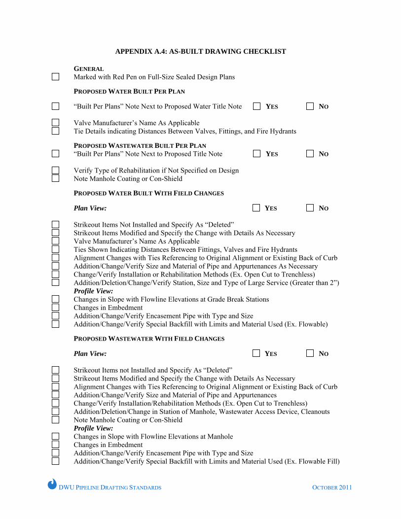
APPENDIX A.4: AS-BUILT DRAWING CHECKLIST
GENERAL Marked with Red Pen on Full-Size Sealed Design Plans
PROPOSED WATER BUILT PER PLAN
“Built Per Plans” Note Next to Proposed Water Title Note
YES NO
Valve Manufacturer’s Name As Applicable Tie Details indicating Distances Between Valves, Fittings, and Fire Hydrants
PROPOSED WASTEWATER BUILT PER PLAN
“Built Per Plans” Note Next to Proposed Title Note YES NO
Verify Type of Rehabilitation if Not Specified on Design Note Manhole Coating or Con-Shield
PROPOSED WATER BUILT WITH FIELD CHANGES
Plan View:
YES NO
Strikeout Items Not Installed and Specify As “Deleted” Strikeout Items Modified and Specify the Change with Details As Necessary Valve Manufacturer’s Name As Applicable Ties Shown Indicating Distances Between Fittings, Valves and Fire Hydrants Alignment Changes with Ties Referencing to Original Alignment or Existing Back of Curb Addition/Change/Verify Size and Material of Pipe and Appurtenances As Necessary Change/Verify Installation or Rehabilitation Methods (Ex. Open Cut to Trenchless) Addition/Deletion/Change/Verify Station, Size and Type of Large Service (Greater than 2”)
Profile View: Changes in Slope with Flowline Elevations at Grade Break Stations Changes in Embedment Addition/Change/Verify Encasement Pipe with Type and Size Addition/Change/Verify Special Backfill with Limits and Material Used (Ex. Flowable)
PROPOSED WASTEWATER WITH FIELD CHANGES
Plan View:
YES NO
Strikeout Items not Installed and Specify As “Deleted” Strikeout Items Modified and Specify the Change with Details As Necessary Alignment Changes with Ties Referencing to Original Alignment or Existing Back of Curb Addition/Change/Verify Size and Material of Pipe and Appurtenances Change/Verify Installation/Rehabilitation Methods (Ex. Open Cut to Trenchless) Addition/Deletion/Change in Station of Manhole, Wastewater Access Device, Cleanouts Note Manhole Coating or Con-Shield
Profile View: Changes in Slope with Flowline Elevations at Manhole Changes in Embedment Addition/Change/Verify Encasement Pipe with Type and Size Addition/Change/Verify Special Backfill with Limits and Material Used (Ex. Flowable Fill)
DWU PIPELINE DRAFTING STANDARDS OCTOBER 2011
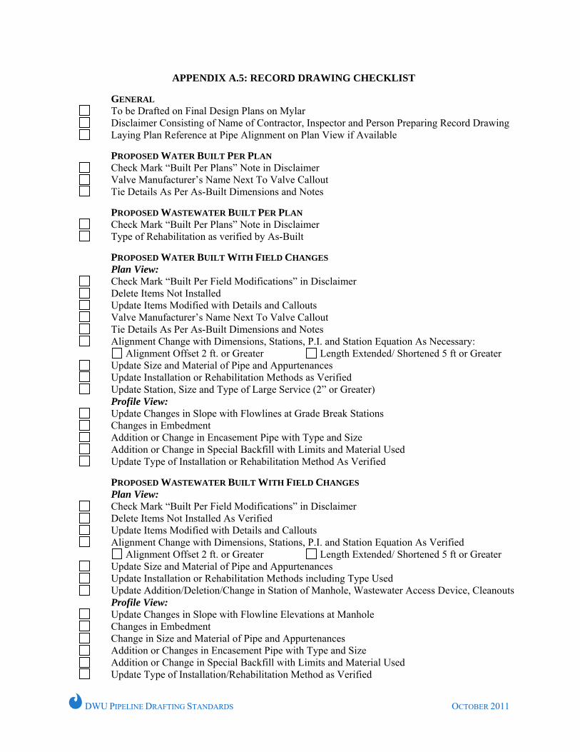
APPENDIX A.5: RECORD DRAWING CHECKLIST
GENERAL
To be Drafted on Final Design Plans on Mylar Disclaimer Consisting of Name of Contractor, Inspector and Person Preparing Record Drawing Laying Plan Reference at Pipe Alignment on Plan View if Available
PROPOSED WATER BUILT PER PLAN
Check Mark “Built Per Plans” Note in Disclaimer Valve Manufacturer’s Name Next To Valve Callout Tie Details As Per As-Built Dimensions and Notes
PROPOSED WASTEWATER BUILT PER PLAN
Check Mark “Built Per Plans” Note in Disclaimer Type of Rehabilitation as verified by As-Built
PROPOSED WATER BUILT WITH FIELD CHANGES Plan View:
Check Mark “Built Per Field Modifications” in Disclaimer Delete Items Not Installed Update Items Modified with Details and Callouts Valve Manufacturer’s Name Next To Valve Callout Tie Details As Per As-Built Dimensions and Notes Alignment Change with Dimensions, Stations, P.I. and Station Equation As Necessary:
Alignment Offset 2 ft. or Greater Length Extended/ Shortened 5 ft or Greater Update Size and Material of Pipe and Appurtenances Update Installation or Rehabilitation Methods as Verified Update Station, Size and Type of Large Service (2” or Greater)
Profile View: Update Changes in Slope with Flowlines at Grade Break Stations Changes in Embedment Addition or Change in Encasement Pipe with Type and Size Addition or Change in Special Backfill with Limits and Material Used Update Type of Installation or Rehabilitation Method As Verified
PROPOSED WASTEWATER BUILT WITH FIELD CHANGES Plan View:
Check Mark “Built Per Field Modifications” in Disclaimer Delete Items Not Installed As Verified Update Items Modified with Details and Callouts Alignment Change with Dimensions, Stations, P.I. and Station Equation As Verified
Alignment Offset 2 ft. or Greater Length Extended/ Shortened 5 ft or Greater Update Size and Material of Pipe and Appurtenances Update Installation or Rehabilitation Methods including Type Used Update Addition/Deletion/Change in Station of Manhole, Wastewater Access Device, Cleanouts
Profile View: Update Changes in Slope with Flowline Elevations at Manhole Changes in Embedment Change in Size and Material of Pipe and Appurtenances Addition or Changes in Encasement Pipe with Type and Size Addition or Change in Special Backfill with Limits and Material Used Update Type of Installation/Rehabilitation Method as Verified
DWU PIPELINE DRAFTING STANDARDS OCTOBER 2011
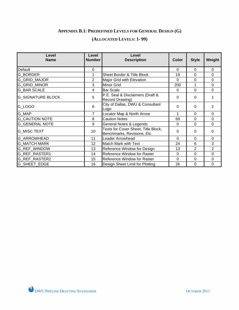
APPENDIX B.1: PREDEFINED LEVELS FOR GENERAL DESIGN (G)
(ALLOCATED LEVELS: 1- 99)
Level Name
Level Number
Level Description
Color
Style
Weight
Default 0 0 0 0 G_BORDER 1 Sheet Border & Title Block 19 0 0 G_GRID_MAJOR 2 Major Grid with Elevation 0 0 0 G_GRID_MINOR 3 Minor Grid 200 1 0 G_BAR SCALE 4 Bar Scale 0 0 0
G_SIGNATURE BLOCK 5 P.E. Seal & Disclaimers (Draft & Record Drawing) 0 0 1
G_LOGO 6 City of Dallas, DWU & Consultant Logo 0 0 2
G_MAP 7 Locator Map & North Arrow 1 0 0 G_CAUTION NOTE 8 Caution Notes 69 0 0 G_GENERAL NOTE 9 General Notes & Legends 0 0 0
G_MISC TEXT 10 Texts for Cover Sheet, Title Block, Benchmarks, Revisions, Etc 0 0 0
G_ARROWHEAD 11 Leader Arrowhead 0 0 0 G_MATCH MARK 12 Match Mark with Text 24 6 3 G_REF_WINDOW 13 Reference Window for Design 13 2 2 G_REF_RASTER1 14 Reference Window for Raster 0 0 0 G_REF_RASTER2 15 Reference Window for Raster 0 0 0 G_SHEET_EDGE 16 Design Sheet Limit for Plotting 26 0 0
DWU PIPELINE DRAFTING STANDARDS OCTOBER 2011
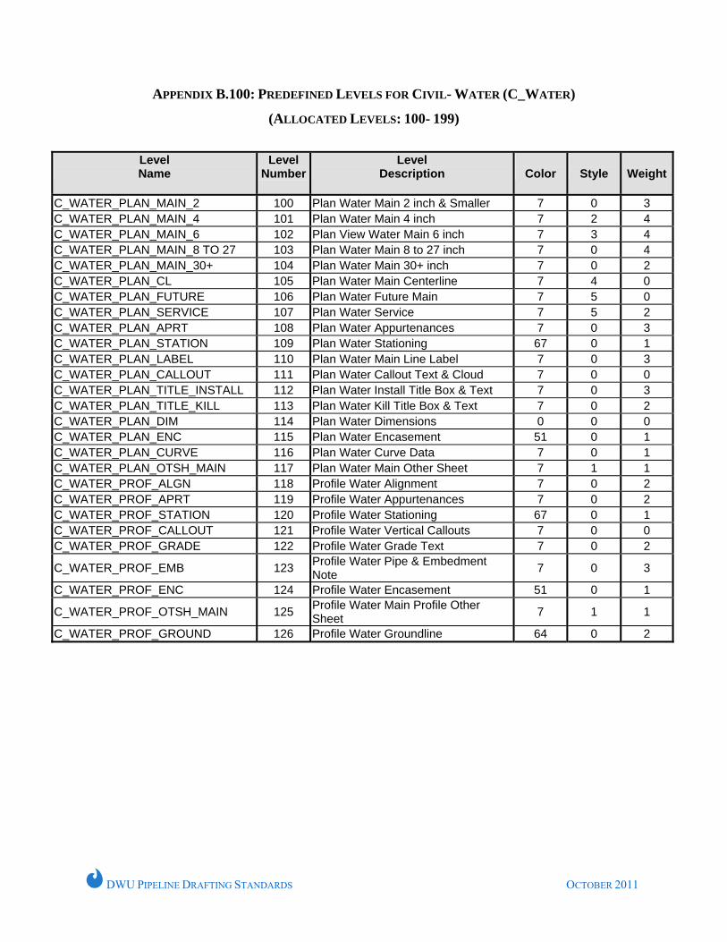
APPENDIX B.100: PREDEFINED LEVELS FOR CIVIL- WATER (C_WATER)
(ALLOCATED LEVELS: 100- 199)
Level Name
Level Number
Level Description
Color
Style
Weight
C_WATER_PLAN_MAIN_2 100 Plan Water Main 2 inch & Smaller 7 0 3 C_WATER_PLAN_MAIN_4 101 Plan Water Main 4 inch 7 2 4 C_WATER_PLAN_MAIN_6 102 Plan View Water Main 6 inch 7 3 4 C_WATER_PLAN_MAIN_8 TO 27 103 Plan Water Main 8 to 27 inch 7 0 4 C_WATER_PLAN_MAIN_30+ 104 Plan Water Main 30+ inch 7 0 2 C_WATER_PLAN_CL 105 Plan Water Main Centerline 7 4 0 C_WATER_PLAN_FUTURE 106 Plan Water Future Main 7 5 0 C_WATER_PLAN_SERVICE 107 Plan Water Service 7 5 2 C_WATER_PLAN_APRT 108 Plan Water Appurtenances 7 0 3 C_WATER_PLAN_STATION 109 Plan Water Stationing 67 0 1 C_WATER_PLAN_LABEL 110 Plan Water Main Line Label 7 0 3 C_WATER_PLAN_CALLOUT 111 Plan Water Callout Text & Cloud 7 0 0 C_WATER_PLAN_TITLE_INSTALL 112 Plan Water Install Title Box & Text 7 0 3 C_WATER_PLAN_TITLE_KILL 113 Plan Water Kill Title Box & Text 7 0 2 C_WATER_PLAN_DIM 114 Plan Water Dimensions 0 0 0 C_WATER_PLAN_ENC 115 Plan Water Encasement 51 0 1 C_WATER_PLAN_CURVE 116 Plan Water Curve Data 7 0 1 C_WATER_PLAN_OTSH_MAIN 117 Plan Water Main Other Sheet 7 1 1 C_WATER_PROF_ALGN 118 Profile Water Alignment 7 0 2 C_WATER_PROF_APRT 119 Profile Water Appurtenances 7 0 2 C_WATER_PROF_STATION 120 Profile Water Stationing 67 0 1 C_WATER_PROF_CALLOUT 121 Profile Water Vertical Callouts 7 0 0 C_WATER_PROF_GRADE 122 Profile Water Grade Text 7 0 2
C_WATER_PROF_EMB 123 Profile Water Pipe & Embedment Note 7 0 3
C_WATER_PROF_ENC 124 Profile Water Encasement 51 0 1
C_WATER_PROF_OTSH_MAIN 125 Profile Water Main Profile Other Sheet 7 1 1
C_WATER_PROF_GROUND 126 Profile Water Groundline 64 0 2
DWU PIPELINE DRAFTING STANDARDS OCTOBER 2011
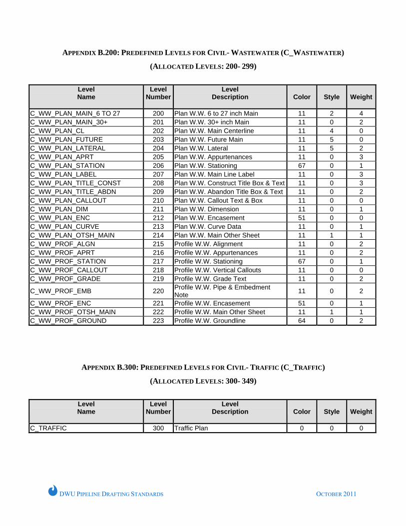
APPENDIX B.200: PREDEFINED LEVELS FOR CIVIL- WASTEWATER (C_WASTEWATER)
(ALLOCATED LEVELS: 200- 299)
Level Name
Level Number
Level Description
Color
Style
Weight
C_WW_PLAN_MAIN_6 TO 27 200 Plan W.W. 6 to 27 inch Main 11 2 4 C_WW_PLAN_MAIN_30+ 201 Plan W.W. 30+ inch Main 11 0 2 C_WW_PLAN_CL 202 Plan W.W. Main Centerline 11 4 0 C_WW_PLAN_FUTURE 203 Plan W.W. Future Main 11 5 0 C_WW_PLAN_LATERAL 204 Plan W.W. Lateral 11 5 2 C_WW_PLAN_APRT 205 Plan W.W. Appurtenances 11 0 3 C_WW_PLAN_STATION 206 Plan W.W. Stationing 67 0 1 C_WW_PLAN_LABEL 207 Plan W.W. Main Line Label 11 0 3 C_WW_PLAN_TITLE_CONST 208 Plan W.W. Construct Title Box & Text 11 0 3 C_WW_PLAN_TITLE_ABDN 209 Plan W.W. Abandon Title Box & Text 11 0 2 C_WW_PLAN_CALLOUT 210 Plan W.W. Callout Text & Box 11 0 0 C_WW_PLAN_DIM 211 Plan W.W. Dimension 11 0 1 C_WW_PLAN_ENC 212 Plan W.W. Encasement 51 0 0 C_WW_PLAN_CURVE 213 Plan W.W. Curve Data 11 0 1 C_WW_PLAN_OTSH_MAIN 214 Plan W.W. Main Other Sheet 11 1 1 C_WW_PROF_ALGN 215 Profile W.W. Alignment 11 0 2 C_WW_PROF_APRT 216 Profile W.W. Appurtenances 11 0 2 C_WW_PROF_STATION 217 Profile W.W. Stationing 67 0 1 C_WW_PROF_CALLOUT 218 Profile W.W. Vertical Callouts 11 0 0 C_WW_PROF_GRADE 219 Profile W.W. Grade Text 11 0 2
C_WW_PROF_EMB 220 Profile W.W. Pipe & Embedment Note 11 0 2
C_WW_PROF_ENC 221 Profile W.W. Encasement 51 0 1 C_WW_PROF_OTSH_MAIN 222 Profile W.W. Main Other Sheet 11 1 1 C_WW_PROF_GROUND 223 Profile W.W. Groundline 64 0 2
APPENDIX B.300: PREDEFINED LEVELS FOR CIVIL- TRAFFIC (C_TRAFFIC)
(ALLOCATED LEVELS: 300- 349)
Level Name
Level Number
Level Description
Color
Style
Weight
C_TRAFFIC 300 Traffic Plan 0 0 0
DWU PIPELINE DRAFTING STANDARDS OCTOBER 2011
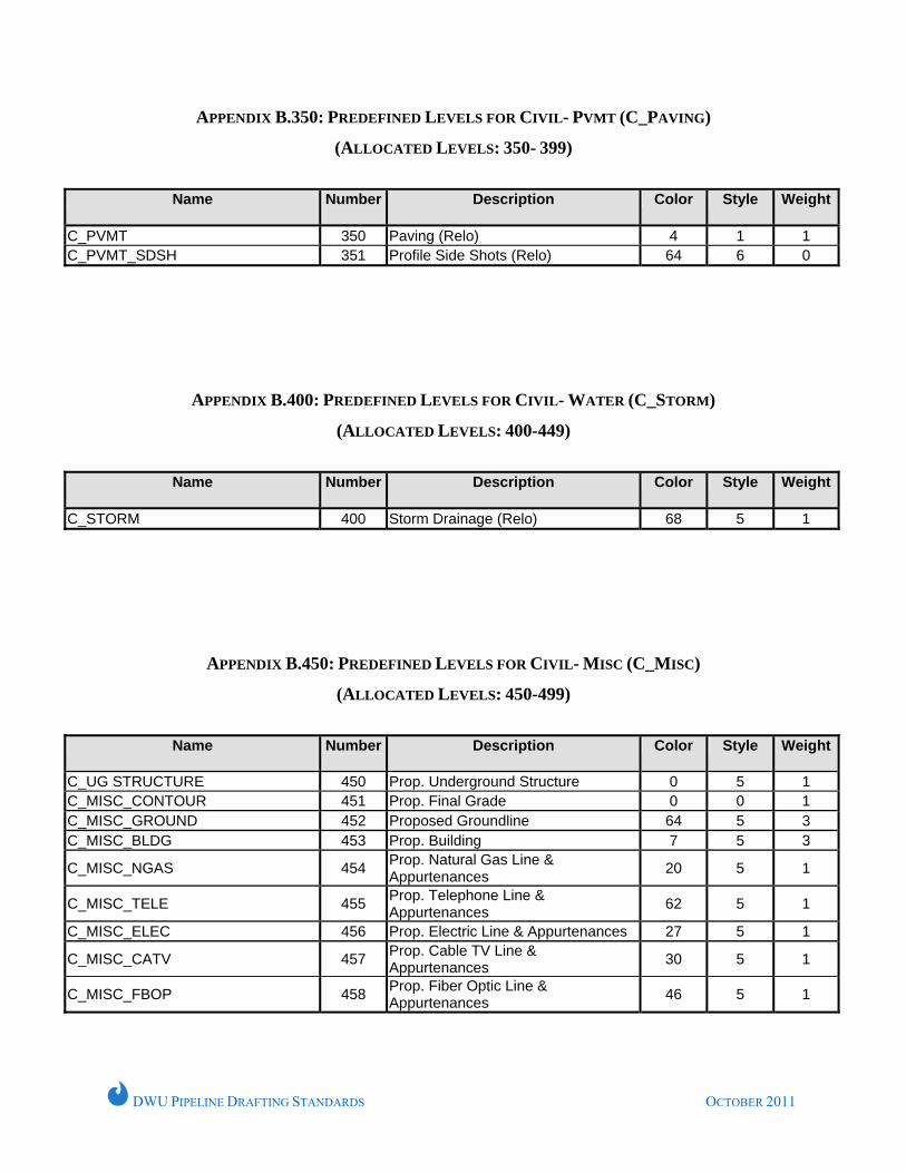
APPENDIX B.350: PREDEFINED LEVELS FOR CIVIL- PVMT (C_PAVING)
(ALLOCATED LEVELS: 350- 399)
Name Number
Description Color Style Weight
C_PVMT 350 Paving (Relo) 4 1 1 C_PVMT_SDSH 351 Profile Side Shots (Relo) 64 6 0
APPENDIX B.400: PREDEFINED LEVELS FOR CIVIL- WATER (C_STORM)
(ALLOCATED LEVELS: 400-449)
Name Number
Description Color Style Weight
C_STORM 400 Storm Drainage (Relo) 68 5 1
APPENDIX B.450: PREDEFINED LEVELS FOR CIVIL- MISC (C_MISC)
(ALLOCATED LEVELS: 450-499)
Name Number
Description Color Style Weight
C_UG STRUCTURE 450 Prop. Underground Structure 0 5 1 C_MISC_CONTOUR 451 Prop. Final Grade 0 0 1 C_MISC_GROUND 452 Proposed Groundline 64 5 3 C_MISC_BLDG 453 Prop. Building 7 5 3
C_MISC_NGAS 454 Prop. Natural Gas Line & Appurtenances 20 5 1
C_MISC_TELE 455 Prop. Telephone Line & Appurtenances 62 5 1
C_MISC_ELEC 456 Prop. Electric Line & Appurtenances 27 5 1
C_MISC_CATV 457 Prop. Cable TV Line & Appurtenances 30 5 1
C_MISC_FBOP 458 Prop. Fiber Optic Line & Appurtenances 46 5 1
DWU PIPELINE DRAFTING STANDARDS OCTOBER 2011
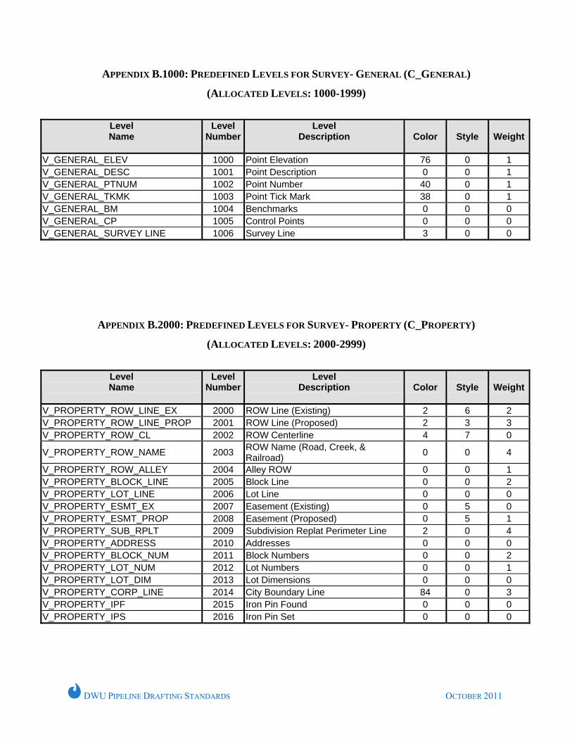
APPENDIX B.1000: PREDEFINED LEVELS FOR SURVEY- GENERAL (C_GENERAL)
(ALLOCATED LEVELS: 1000-1999)
Level Name
Level Number
Level Description
Color
Style
Weight
V_GENERAL_ELEV 1000 Point Elevation 76 0 1 V_GENERAL_DESC 1001 Point Description 0 0 1 V_GENERAL_PTNUM 1002 Point Number 40 0 1 V_GENERAL_TKMK 1003 Point Tick Mark 38 0 1 V_GENERAL_BM 1004 Benchmarks 0 0 0 V_GENERAL_CP 1005 Control Points 0 0 0 V_GENERAL_SURVEY LINE 1006 Survey Line 3 0 0
APPENDIX B.2000: PREDEFINED LEVELS FOR SURVEY- PROPERTY (C_PROPERTY)
(ALLOCATED LEVELS: 2000-2999)
Level Name
Level Number
Level Description
Color
Style
Weight
V_PROPERTY_ROW_LINE_EX 2000 ROW Line (Existing) 2 6 2 V_PROPERTY_ROW_LINE_PROP 2001 ROW Line (Proposed) 2 3 3 V_PROPERTY_ROW_CL 2002 ROW Centerline 4 7 0
V_PROPERTY_ROW_NAME 2003 ROW Name (Road, Creek, & Railroad) 0 0 4
V_PROPERTY_ROW_ALLEY 2004 Alley ROW 0 0 1 V_PROPERTY_BLOCK_LINE 2005 Block Line 0 0 2 V_PROPERTY_LOT_LINE 2006 Lot Line 0 0 0 V_PROPERTY_ESMT_EX 2007 Easement (Existing) 0 5 0 V_PROPERTY_ESMT_PROP 2008 Easement (Proposed) 0 5 1 V_PROPERTY_SUB_RPLT 2009 Subdivision Replat Perimeter Line 2 0 4 V_PROPERTY_ADDRESS 2010 Addresses 0 0 0 V_PROPERTY_BLOCK_NUM 2011 Block Numbers 0 0 2 V_PROPERTY_LOT_NUM 2012 Lot Numbers 0 0 1 V_PROPERTY_LOT_DIM 2013 Lot Dimensions 0 0 0 V_PROPERTY_CORP_LINE 2014 City Boundary Line 84 0 3 V_PROPERTY_IPF 2015 Iron Pin Found 0 0 0 V_PROPERTY_IPS 2016 Iron Pin Set 0 0 0
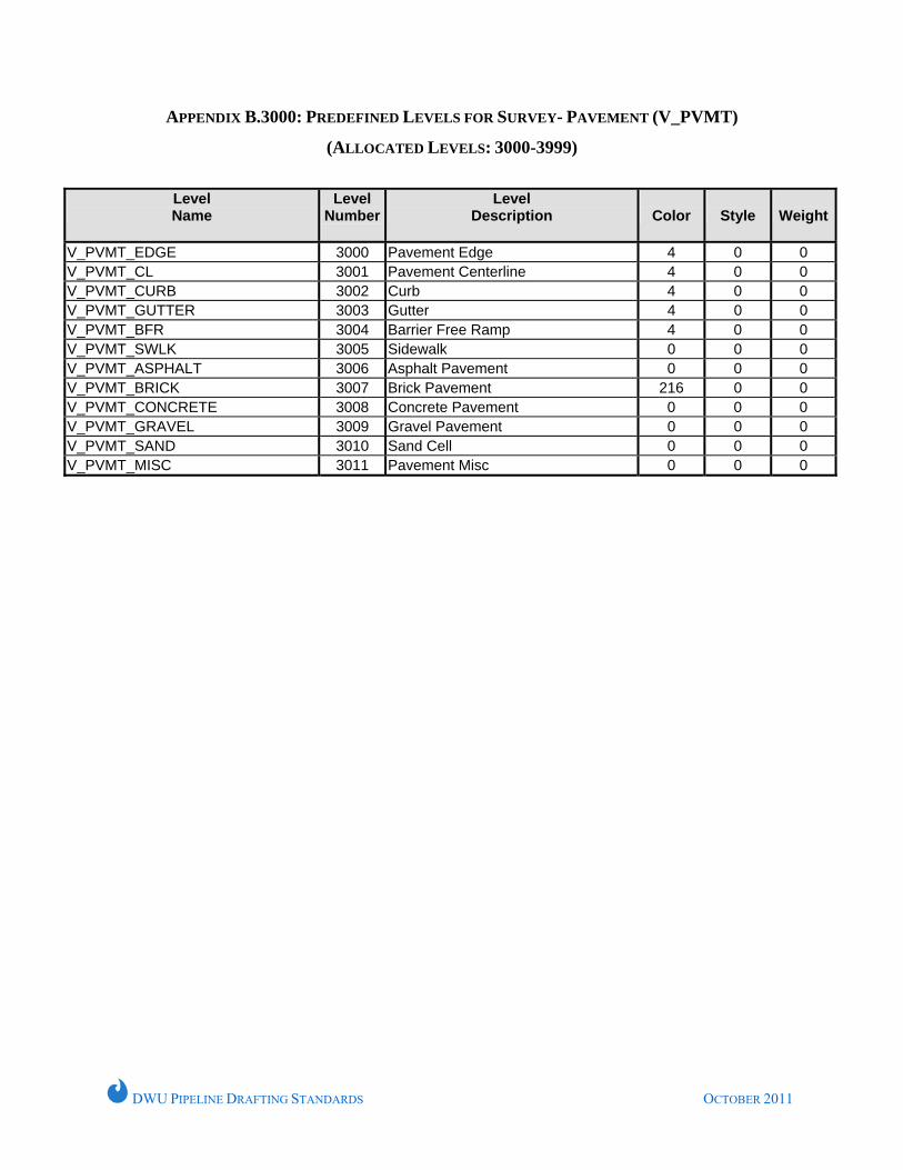
DWU PIPELINE DRAFTING STANDARDS OCTOBER 2011
APPENDIX B.3000: PREDEFINED LEVELS FOR SURVEY- PAVEMENT (V_PVMT)
(ALLOCATED LEVELS: 3000-3999)
Level Name
Level Number
Level Description
Color
Style
Weight
V_PVMT_EDGE 3000 Pavement Edge 4 0 0 V_PVMT_CL 3001 Pavement Centerline 4 0 0 V_PVMT_CURB 3002 Curb 4 0 0 V_PVMT_GUTTER 3003 Gutter 4 0 0 V_PVMT_BFR 3004 Barrier Free Ramp 4 0 0 V_PVMT_SWLK 3005 Sidewalk 0 0 0 V_PVMT_ASPHALT 3006 Asphalt Pavement 0 0 0 V_PVMT_BRICK 3007 Brick Pavement 216 0 0 V_PVMT_CONCRETE 3008 Concrete Pavement 0 0 0 V_PVMT_GRAVEL 3009 Gravel Pavement 0 0 0 V_PVMT_SAND 3010 Sand Cell 0 0 0 V_PVMT_MISC 3011 Pavement Misc 0 0 0
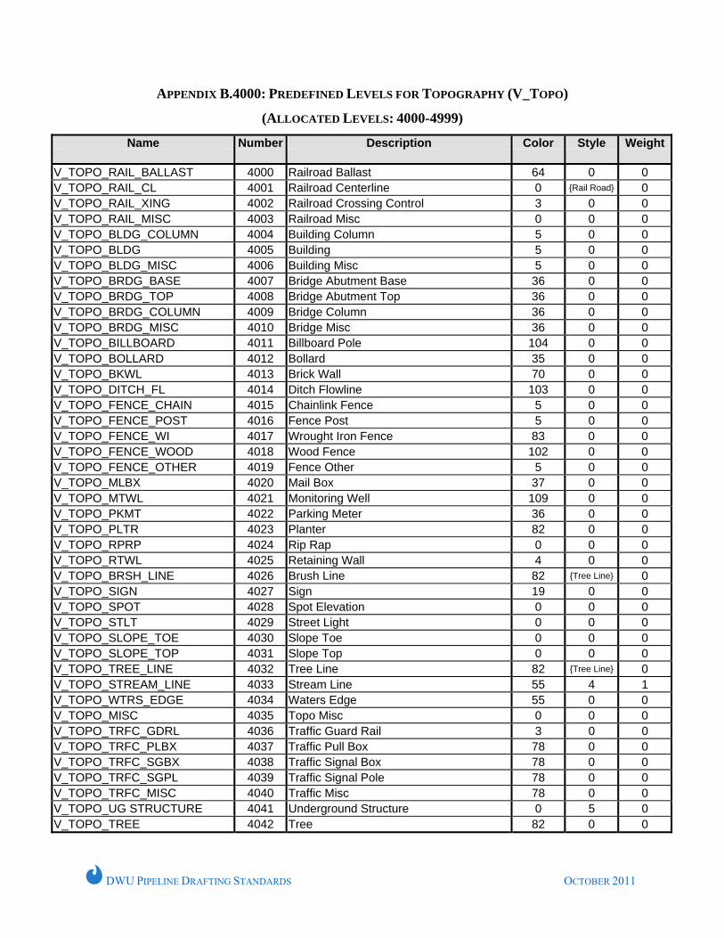
DWU PIPELINE DRAFTING STANDARDS OCTOBER 2011
APPENDIX B.4000: PREDEFINED LEVELS FOR TOPOGRAPHY (V_TOPO)
(ALLOCATED LEVELS: 4000-4999)
Name Number
Description Color Style Weight
V_TOPO_RAIL_BALLAST 4000 Railroad Ballast 64 0 0 V_TOPO_RAIL_CL 4001 Railroad Centerline 0 {Rail Road} 0 V_TOPO_RAIL_XING 4002 Railroad Crossing Control 3 0 0 V_TOPO_RAIL_MISC 4003 Railroad Misc 0 0 0 V_TOPO_BLDG_COLUMN 4004 Building Column 5 0 0 V_TOPO_BLDG 4005 Building 5 0 0 V_TOPO_BLDG_MISC 4006 Building Misc 5 0 0 V_TOPO_BRDG_BASE 4007 Bridge Abutment Base 36 0 0 V_TOPO_BRDG_TOP 4008 Bridge Abutment Top 36 0 0 V_TOPO_BRDG_COLUMN 4009 Bridge Column 36 0 0 V_TOPO_BRDG_MISC 4010 Bridge Misc 36 0 0 V_TOPO_BILLBOARD 4011 Billboard Pole 104 0 0 V_TOPO_BOLLARD 4012 Bollard 35 0 0 V_TOPO_BKWL 4013 Brick Wall 70 0 0 V_TOPO_DITCH_FL 4014 Ditch Flowline 103 0 0 V_TOPO_FENCE_CHAIN 4015 Chainlink Fence 5 0 0 V_TOPO_FENCE_POST 4016 Fence Post 5 0 0 V_TOPO_FENCE_WI 4017 Wrought Iron Fence 83 0 0 V_TOPO_FENCE_WOOD 4018 Wood Fence 102 0 0 V_TOPO_FENCE_OTHER 4019 Fence Other 5 0 0 V_TOPO_MLBX 4020 Mail Box 37 0 0 V_TOPO_MTWL 4021 Monitoring Well 109 0 0 V_TOPO_PKMT 4022 Parking Meter 36 0 0 V_TOPO_PLTR 4023 Planter 82 0 0 V_TOPO_RPRP 4024 Rip Rap 0 0 0 V_TOPO_RTWL 4025 Retaining Wall 4 0 0 V_TOPO_BRSH_LINE 4026 Brush Line 82 {Tree Line} 0 V_TOPO_SIGN 4027 Sign 19 0 0 V_TOPO_SPOT 4028 Spot Elevation 0 0 0 V_TOPO_STLT 4029 Street Light 0 0 0 V_TOPO_SLOPE_TOE 4030 Slope Toe 0 0 0 V_TOPO_SLOPE_TOP 4031 Slope Top 0 0 0 V_TOPO_TREE_LINE 4032 Tree Line 82 {Tree Line} 0 V_TOPO_STREAM_LINE 4033 Stream Line 55 4 1 V_TOPO_WTRS_EDGE 4034 Waters Edge 55 0 0 V_TOPO_MISC 4035 Topo Misc 0 0 0 V_TOPO_TRFC_GDRL 4036 Traffic Guard Rail 3 0 0 V_TOPO_TRFC_PLBX 4037 Traffic Pull Box 78 0 0 V_TOPO_TRFC_SGBX 4038 Traffic Signal Box 78 0 0 V_TOPO_TRFC_SGPL 4039 Traffic Signal Pole 78 0 0 V_TOPO_TRFC_MISC 4040 Traffic Misc 78 0 0 V_TOPO_UG STRUCTURE 4041 Underground Structure 0 5 0 V_TOPO_TREE 4042 Tree 82 0 0
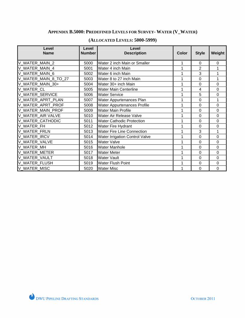
DWU PIPELINE DRAFTING STANDARDS OCTOBER 2011
APPENDIX B.5000: PREDEFINED LEVELS FOR SURVEY- WATER (V_WATER)
(ALLOCATED LEVELS: 5000-5999)
Level Name
Level Number
Level Description
Color
Style
Weight
V_WATER_MAIN_2 5000 Water 2 inch Main or Smaller 1 0 0 V_WATER_MAIN_4 5001 Water 4 inch Main 1 2 1 V_WATER_MAIN_6 5002 Water 6 inch Main 1 3 1 V_WATER_MAIN_8_TO_27 5003 Water 8 to 27 inch Main 1 0 1 V_WATER_MAIN_30+ 5004 Water 30+ inch Main 1 0 0 V_WATER_CL 5005 Water Main Centerline 1 4 0 V_WATER_SERVICE 5006 Water Service 1 5 0 V_WATER_APRT_PLAN 5007 Water Appurtenances Plan 1 0 1 V_WATER_APRT_PROF 5008 Water Appurtenances Profile 1 0 0 V_WATER_MAIN_PROF 5009 Water Main Profile 1 0 0 V_WATER_AIR VALVE 5010 Water Air Release Valve 1 0 0 V_WATER_CATHODIC 5011 Water Cathodic Protection 1 0 0 V_WATER_FH 5012 Water Fire Hydrant 1 0 0 V_WATER_FRLN 5013 Water Fire Line Connection 1 3 1 V_WATER_IRCV 5014 Water Irrigation Control Valve 1 0 0 V_WATER_VALVE 5015 Water Valve 1 0 0 V_WATER_MH 5016 Water Manhole 1 0 0 V_WATER_METER 5017 Water Meter 1 0 0 V_WATER_VAULT 5018 Water Vault 1 0 0 V_WATER_FLUSH 5019 Water Flush Point 1 0 0 V_WATER_MISC 5020 Water Misc 1 0 0
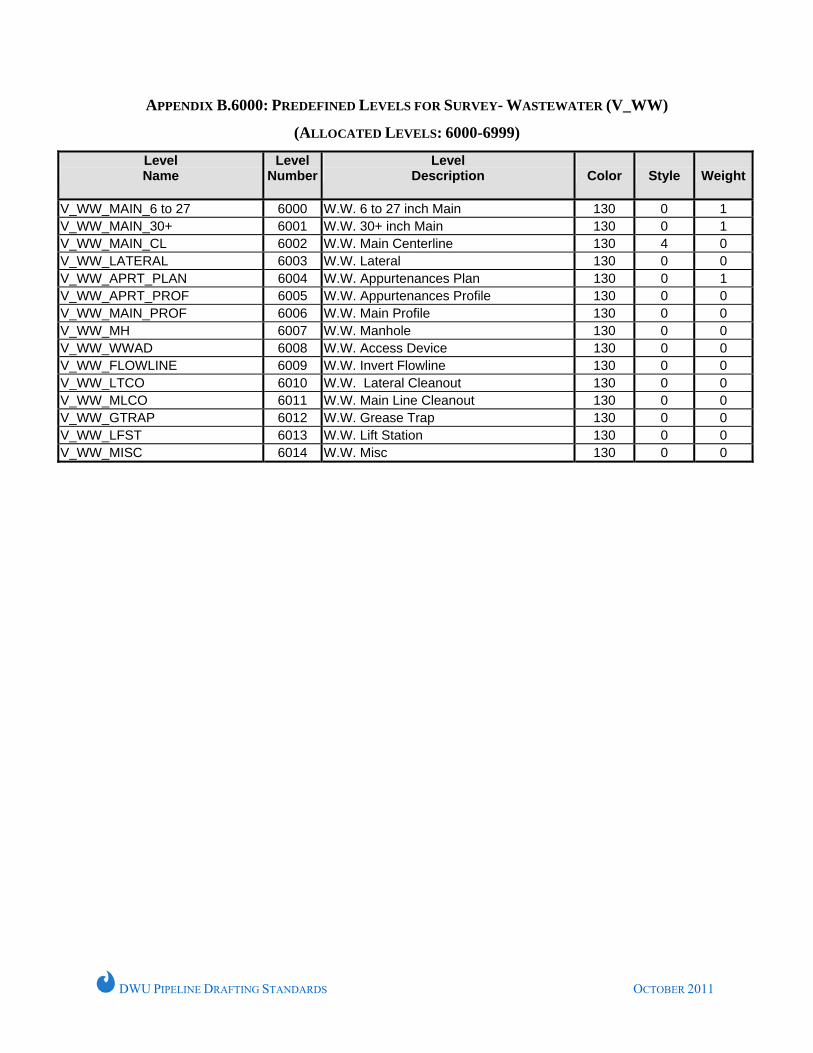
DWU PIPELINE DRAFTING STANDARDS OCTOBER 2011
APPENDIX B.6000: PREDEFINED LEVELS FOR SURVEY- WASTEWATER (V_WW)
(ALLOCATED LEVELS: 6000-6999)
Level Name
Level Number
Level Description
Color
Style
Weight
V_WW_MAIN_6 to 27 6000 W.W. 6 to 27 inch Main 130 0 1 V_WW_MAIN_30+ 6001 W.W. 30+ inch Main 130 0 1 V_WW_MAIN_CL 6002 W.W. Main Centerline 130 4 0 V_WW_LATERAL 6003 W.W. Lateral 130 0 0 V_WW_APRT_PLAN 6004 W.W. Appurtenances Plan 130 0 1 V_WW_APRT_PROF 6005 W.W. Appurtenances Profile 130 0 0 V_WW_MAIN_PROF 6006 W.W. Main Profile 130 0 0 V_WW_MH 6007 W.W. Manhole 130 0 0 V_WW_WWAD 6008 W.W. Access Device 130 0 0 V_WW_FLOWLINE 6009 W.W. Invert Flowline 130 0 0 V_WW_LTCO 6010 W.W. Lateral Cleanout 130 0 0 V_WW_MLCO 6011 W.W. Main Line Cleanout 130 0 0 V_WW_GTRAP 6012 W.W. Grease Trap 130 0 0 V_WW_LFST 6013 W.W. Lift Station 130 0 0 V_WW_MISC 6014 W.W. Misc 130 0 0
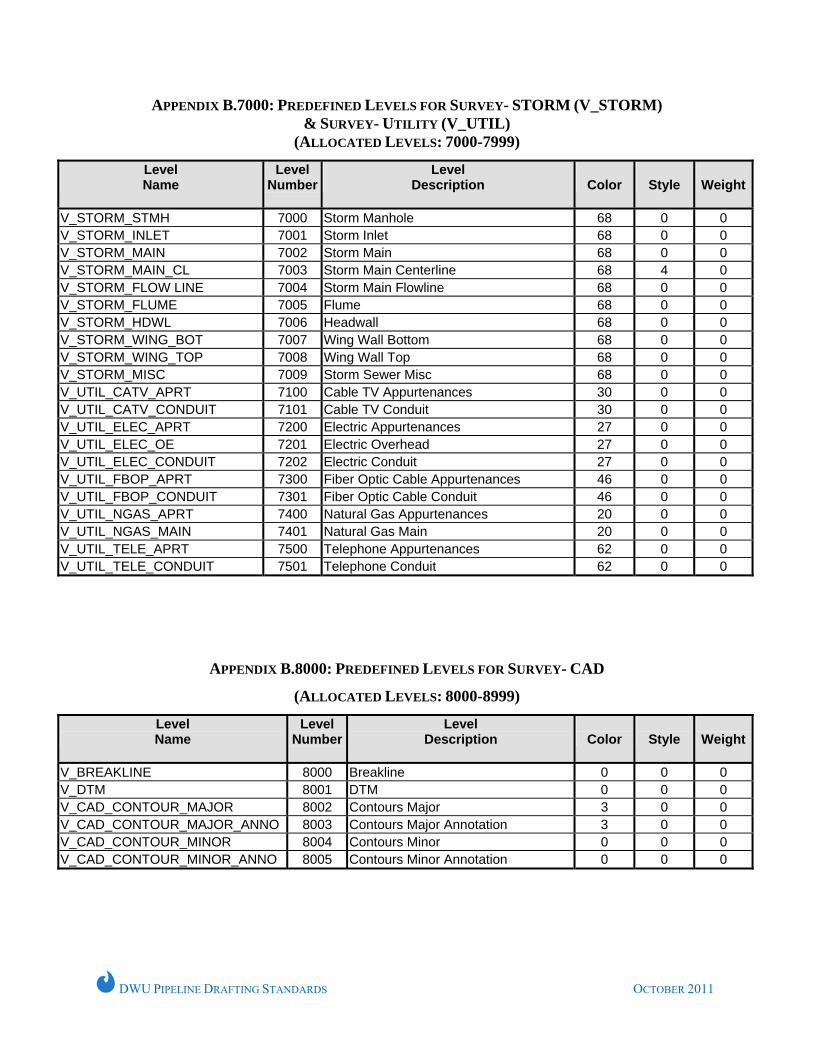
DWU PIPELINE DRAFTING STANDARDS OCTOBER 2011
APPENDIX B.7000: PREDEFINED LEVELS FOR SURVEY- STORM (V_STORM) & SURVEY- UTILITY (V_UTIL)
(ALLOCATED LEVELS: 7000-7999)
Level Name
Level Number
Level Description
Color
Style
Weight
V_STORM_STMH 7000 Storm Manhole 68 0 0 V_STORM_INLET 7001 Storm Inlet 68 0 0 V_STORM_MAIN 7002 Storm Main 68 0 0 V_STORM_MAIN_CL 7003 Storm Main Centerline 68 4 0 V_STORM_FLOW LINE 7004 Storm Main Flowline 68 0 0 V_STORM_FLUME 7005 Flume 68 0 0 V_STORM_HDWL 7006 Headwall 68 0 0 V_STORM_WING_BOT 7007 Wing Wall Bottom 68 0 0 V_STORM_WING_TOP 7008 Wing Wall Top 68 0 0 V_STORM_MISC 7009 Storm Sewer Misc 68 0 0 V_UTIL_CATV_APRT 7100 Cable TV Appurtenances 30 0 0 V_UTIL_CATV_CONDUIT 7101 Cable TV Conduit 30 0 0 V_UTIL_ELEC_APRT 7200 Electric Appurtenances 27 0 0 V_UTIL_ELEC_OE 7201 Electric Overhead 27 0 0 V_UTIL_ELEC_CONDUIT 7202 Electric Conduit 27 0 0 V_UTIL_FBOP_APRT 7300 Fiber Optic Cable Appurtenances 46 0 0 V_UTIL_FBOP_CONDUIT 7301 Fiber Optic Cable Conduit 46 0 0 V_UTIL_NGAS_APRT 7400 Natural Gas Appurtenances 20 0 0 V_UTIL_NGAS_MAIN 7401 Natural Gas Main 20 0 0 V_UTIL_TELE_APRT 7500 Telephone Appurtenances 62 0 0 V_UTIL_TELE_CONDUIT 7501 Telephone Conduit 62 0 0
APPENDIX B.8000: PREDEFINED LEVELS FOR SURVEY- CAD
(ALLOCATED LEVELS: 8000-8999)
Level Name
Level Number
Level Description
Color
Style
Weight
V_BREAKLINE 8000 Breakline 0 0 0 V_DTM 8001 DTM 0 0 0 V_CAD_CONTOUR_MAJOR 8002 Contours Major 3 0 0 V_CAD_CONTOUR_MAJOR_ANNO 8003 Contours Major Annotation 3 0 0 V_CAD_CONTOUR_MINOR 8004 Contours Minor 0 0 0 V_CAD_CONTOUR_MINOR_ANNO 8005 Contours Minor Annotation 0 0 0