Embed Size (px)
Citation preview
2008-2862Aeroacoustic Simulations of Tandem Cylinders
with Subcritical Spacing
David P. Lockard∗, Meelan M. Choudhari†, Mehdi R. Khorrami†,Dan H. Neuhart‡, Florence V. Hutcheson§, Thomas F. Brooks¶
NASA Langley Research Center, Hampton, VA 23681
andDaniel J. Stead‖
Lockheed Martin Engineering and Sciences, Hampton, VA 23681
Tandem cylinders are being studied because they model a variety of component level interactions of landinggear. The present effort is directed at the case of two identical cylinders with their centroids separated in thestreamwise direction by 1.435 diameters. Experiments in the Basic Aerodynamic Research Tunnel and QuietFlow Facility at NASA Langley Research Center have provided an extensive experimental database of the near-field flow and radiated noise. The measurements were conducted at a Mach number of 0.1285 and Reynoldsnumber of 1.66× 10⁵ based on the cylinder diameter. A trip was used on the upstream cylinder to insure a fullyturbulent flow separation and, hence, to simulate a major aspect of high Reynolds number flow. The parallelcomputational effort uses the three-dimensional Navier-Stokes solver CFL3D with a hybrid, zonal turbulencemodel that turns off the turbulence production term everywhere except in a narrow ring surrounding solid sur-faces. The experiments exhibited an asymmetry in the surface pressure that was persistent despite attemptsto eliminate it through small changes in the configuration. To model the asymmetry, the simulations were runwith the cylinder configuration at a nonzero but small angle of attack. The computed results and experimentsare in general agreement that vortex shedding for the spacing studied herein is weak relative to that observedat supercritical spacings. Although the shedding was subdued in the simulations, it was still more prominentthan in the experiments. Overall, the simulation comparisons with measured near-field data and the radiatedacoustics are reasonable, especially if one is concerned with capturing the trends relative to larger cylinder spac-ings. However, the flow details of the 1.435 diameter spacing have not been captured in full even though veryfine grid computations have been performed. Some of the discrepancy may be associated with the simulation’sinexact representation of the experimental configuration, but numerical and flow modeling errors are also likelycontributors to the observed differences.
Nomenclature
b spanD cylinder diameterFxyz fine gridM Mach numberMxyz medium gridMxyFz medium grid in x-y plane, fine in the spanp pressureu, v, w Cartesian fluid velocity componentsU, V,W time-averaged velocity componentsx, y, z Cartesian coordinates
Greek:ρ fluid densityθ azimuthal angle
Superscript:′ perturbation quantity (e.g.ρ′ = ρ− ρ∞)
Subscript:
∞ freestream quantity
∗Aerospace Technologist, Computational AeroSciences Branch, Mail Stop 128, Senior Member, AIAA†Aerospace Technologist, Computational AeroSciences Branch, Mail Stop 128, Associate Fellow, AIAA‡Aerospace Technologist, Flow Physics and Controls Branch§Aerospace Technologist, Aeroacoustics Branch, Mail Stop 461, Member, AIAA¶Aerospace Technologist, Aeroacoustics Branch, Mail Stop 461, Fellow, AIAA‖Aerospace Engineer, Aeroacoustics Branch, Mail Stop 461
1 of 16
American Institute of Aeronautics and Astronautics Paper 2008-2862
https://ntrs.nasa.gov/search.jsp?R=20080018593 2020-03-31T20:39:52+00:00Z
I. Introduction
In an effort to better understand landing gear noise sources, the NASA airframe noise team has been examining asimplified configuration that still maintains some of the salient features of landing gear flow fields. In particular, tan-dem cylinders have been studied because they model a variety of component level interactions encountered on aircraftundercarriages. The present effort is directed at the case of two identical cylinders spatially separated in the stream-wise direction. Extensive experimental data1–4 have been collected to investigate the flow fields (especially from thestandpoint of noise generation), but also to provide benchmark data to assess the ability of computational simulationsto capture the relevant features of such flows. An extensive review of the literature on cylinder flows can be found inZdravkovich,5,6 and work of particular relevance to the current study on tandem cylinders is given in references 7 and8. A detailed comparison of experimental and computational results for a streamwise spacing of 3.7 diameters was pre-sented in Lockardet al.4 In the current investigation of tandem cylinders with their centroids separated in the streamwisedirection by 1.435 diameters, we extend our previous work by examining longer span lengths and by making compar-isons with aeroacoustic measurements from the QFF. Earlier computational results and their comparison with both flowand acoustic predictions have been presented by Liuet al.,9 Shetaet al.,10 Frendiet al.,11 and Khorramiet al.12
The Basic Aerodynamic Research Tunnel (BART) and Quiet Flow Facility (QFF) at NASA Langley Research Center(LaRC) have been used to gather the experimental data. The parallel computational effort by Khorramiet al.13,14 ini-tially was restricted to two-dimensional (2-D), fully turbulent simulations using standard, unsteady Reynolds averagedNavier-Stokes (URANS) equations in conjunction with Menter’s15 two-equation, Shear Stress Transport (SST) turbu-lence model. Separation distances of L/D = 1.435 and 3.7 were considered, where D is the diameter and L the distancebetween the cylinder centroids. Zdravkovich8 characterizes flow patterns associated with various separation distancesbetween the cylinders. For L/D< 1.1, the two cylinders behave as a single bluff body with vortex shedding only occur-ring behind the rear cylinder. For 1.1< L/D < 1.6, the shear layers from the front cylinder attach to the rear cylinderalternately or intermittently, and vortex shedding occurs behind the rear cylinder. For 1.6< L/D < 2.5, the shear layersfrom the front cylinder remain attached to the rear cylinder, and vortex shedding occurs behind the rear cylinder. Forseparation distances, 2.5< L/D < 3.2, intermittent shedding can be detected in the region between the cylinders, andvortex shedding occurs behind the rear cylinder. For 3.2< L/D < 3.8, the flow between the cylinders is bistable andswitches between intermittent shedding and constant shedding. For L/D> 3.8, vortex shedding occurs on both cylinderswith the same characteristics as a single cylinder. The behavior within these regimes, and the spacings used to definethem, can vary as the exact flow behavior is dependent on the Reynolds number, span length, and freestream turbulence.The case of the subcritical spacing of 1.435D where shedding only occurs behind the downstream cylinder is perhapsmore relevant in the context of a typical landing gear and forms the subject of this paper.
The 2-D computational results13 for 3.7D and 1.435D spacings showed reasonable overall agreement with the mea-sured data but failed to match the details, especially those of the off-surface mean and fluctuating velocity fields. Apartfrom the shortcomings associated with the 2-D nature of the simulations, those computations produced very strong, co-herent shedding without any small scale structures, presumably because of the overly diffusive nature of the turbulencemodel. Considerable improvement in the comparisons with experiment was achieved by Khorramiet al.12 by extendingthe computations to three-dimensions and using a hybrid, zonal turbulence model that turned off the turbulence produc-tion term everywhere except in a narrow ring surrounding the solid surfaces. Due to the high computational cost of the3D simulations, the spanwise extent of the computational domain was restricted to 3 cylinder diameters. Computationswith the hybrid turbulence model more faithfully reproduced the three dimensionality in the flow, in contrast to 3-DURANS calculations that had shown almost no three-dimensional behavior.
II. Experiments
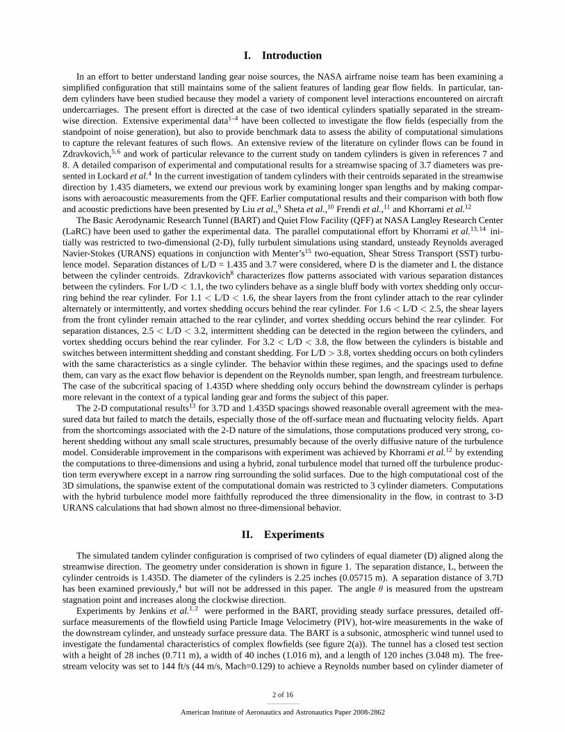
The simulated tandem cylinder configuration is comprised of two cylinders of equal diameter (D) aligned along thestreamwise direction. The geometry under consideration is shown in figure 1. The separation distance, L, between thecylinder centroids is 1.435D. The diameter of the cylinders is 2.25 inches (0.05715 m). A separation distance of 3.7Dhas been examined previously,4 but will not be addressed in this paper. The angleθ is measured from the upstreamstagnation point and increases along the clockwise direction.
Experiments by Jenkinset al.1,2 were performed in the BART, providing steady surface pressures, detailed off-surface measurements of the flowfield using Particle Image Velocimetry (PIV), hot-wire measurements in the wake ofthe downstream cylinder, and unsteady surface pressure data. The BART is a subsonic, atmospheric wind tunnel used toinvestigate the fundamental characteristics of complex flowfields (see figure 2(a)). The tunnel has a closed test sectionwith a height of 28 inches (0.711 m), a width of 40 inches (1.016 m), and a length of 120 inches (3.048 m). The free-stream velocity was set to 144 ft/s (44 m/s, Mach=0.129) to achieve a Reynolds number based on cylinder diameter of
2 of 16
American Institute of Aeronautics and Astronautics Paper 2008-2862
1.66 × 10⁵. At these conditions the free stream turbulence level was less than 0.10%. The cylinders spanned the entireBART tunnel height, such that the aspect ratio during the experiment was b/D = 12.4, where b is the cylinder span. Toensure a fully turbulent shedding process, the boundary layers on the upstream cylinder were tripped between azimuthallocations of 50 and 60 degrees from the leading stagnation point. The measured surface pressure distribution for thelarge separation case was nearly identical to that measured by previous investigators for a single, isolated cylinder at aReynolds number greater than 8 million.16
Figure 1. Schematic of tandem cylinder configuration.
Unsteady surface pressure data were obtained from Endevcotransducers. The data from both a spanwise row (positioned at135◦ )and a 45◦ azimuthally spaced ring of sensors were obtainedsimultaneously. New data from a 2007 entry that focused on morerefined azimuthal resolution of the unsteady surface pressure isincluded in the current paper. The cylinders were rotated in 5◦
increments to obtain data at other angles. The rotations providedmore refined information about the azimuthal variation of the un-steady pressure from the centerline ring as well as the spanwiserow of transducers. Additional information about the BART ex-periments can be found in References 1, 2, and a forthcomingNASA technical report.
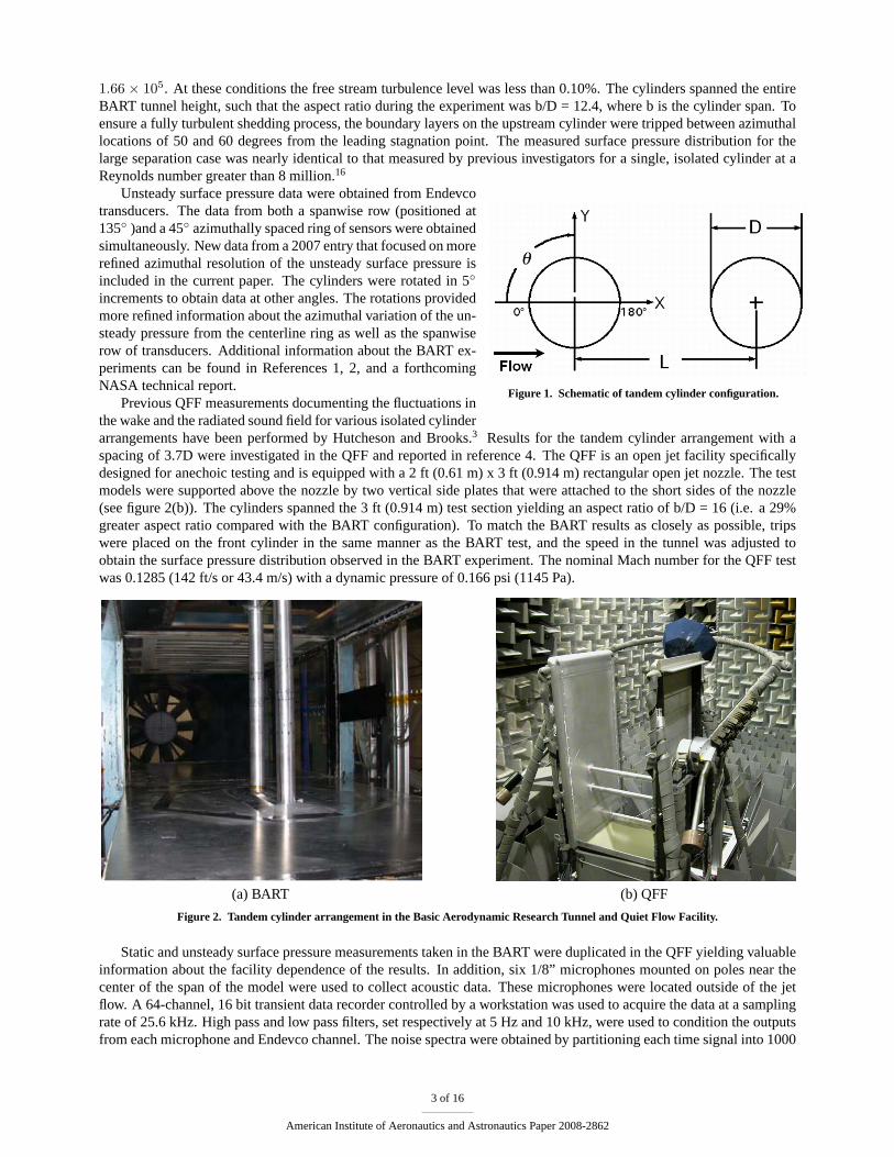
Previous QFF measurements documenting the fluctuations inthe wake and the radiated sound field for various isolated cylinderarrangements have been performed by Hutcheson and Brooks.3 Results for the tandem cylinder arrangement with aspacing of 3.7D were investigated in the QFF and reported in reference 4. The QFF is an open jet facility specificallydesigned for anechoic testing and is equipped with a 2 ft (0.61 m) x 3 ft (0.914 m) rectangular open jet nozzle. The testmodels were supported above the nozzle by two vertical side plates that were attached to the short sides of the nozzle(see figure 2(b)). The cylinders spanned the 3 ft (0.914 m) test section yielding an aspect ratio of b/D = 16 (i.e. a 29%greater aspect ratio compared with the BART configuration). To match the BART results as closely as possible, tripswere placed on the front cylinder in the same manner as the BART test, and the speed in the tunnel was adjusted toobtain the surface pressure distribution observed in the BART experiment. The nominal Mach number for the QFF testwas 0.1285 (142 ft/s or 43.4 m/s) with a dynamic pressure of 0.166 psi (1145 Pa).
(a) BART (b) QFF
Figure 2. Tandem cylinder arrangement in the Basic Aerodynamic Research Tunnel and Quiet Flow Facility.
Static and unsteady surface pressure measurements taken in the BART were duplicated in the QFF yielding valuableinformation about the facility dependence of the results. In addition, six 1/8” microphones mounted on poles near thecenter of the span of the model were used to collect acoustic data. These microphones were located outside of the jetflow. A 64-channel, 16 bit transient data recorder controlled by a workstation was used to acquire the data at a samplingrate of 25.6 kHz. High pass and low pass filters, set respectively at 5 Hz and 10 kHz, were used to condition the outputsfrom each microphone and Endevco channel. The noise spectra were obtained by partitioning each time signal into 1000
3 of 16
American Institute of Aeronautics and Astronautics Paper 2008-2862
non-overlapping segments of 8192 samples, and each time history segment was Fourier transformed using a Hammingwindow for signal conditioning. The resulting frequency resolution was 3.125 Hz.
III. Computational Simulations
This study incorporates a coordinated effort between computations and experiment. The time-dependent CFD simu-lations have been performed using the second-order code CFL3D.17,18 CFL3D was developed at NASA LaRC to solvethe 3-D, time-dependent, thin layer Reynolds-averaged Navier-Stokes (RANS) equations using a finite-volume formula-tion. The unsteady calculations use the shear stress transport (SST)k − ω turbulence model of Menter,15,19 which wasdeveloped for steady flow. Due to the overly diffusive nature of the turbulence model, results from three-dimensionalURANS simulations remained essentially two-dimensional. To remedy this shortcoming, the quasi-laminar approachdescribed in Khorramiet al.12 has been adopted for all three-dimensional computations. Following this approach, theflowfield was assumed to be quasi-laminar, except for a narrow strip surrounding the cylinder surfaces where the SSTturbulence model was used. Outside of this strip, the production term associated with the turbulence model was switchedoff. For computational convenience, the distance from the cylinder at which the switch occurs was set based on a setnumber of grid points from the surface. Because of the azimuthal nonuniformity in the grid stretching, the switch occursbetween 0.01D and 0.04D, which includes the entire boundary layer within the region of attached flow. For different gridspacings, the number of points from the surface was changed to maintain the switching at the same physical distance.
The free stream Mach number in the computations was 0.166, and the Reynolds number was1.66 × 105 basedon the cylinder diameter. The Mach number in the simulations corresponds to the speed used in the first BART tandemcylinder experiments.1 Subsequent experiments employed a cylinder of larger diameter to accommodate surface pressuretransducers. To maintain the Reynolds number, the experiments were run at slightly different speeds. Therefore, thesimulation results have been corrected to an equivalent speed. The BART Mach number of 0.1285 was used as thebaseline. Although the experiments used a trip strip to insure turbulent shedding, directly computing the effects of thetrip is infeasible. Instead, the computations were run in a fully turbulent mode and allowed to transition on their own. Inour calculations, the transition occurs early enough that the flow remains attached to the correct angle for turbulent flow.Even on the rear cylinder, the turbulence model is needed to obtain proper boundary layer development and separation.
III.A. Configurations and Grids
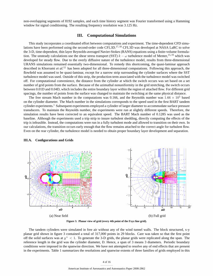
(a) Near field (b) Full grid
Figure 3. Planar view of grid (every 4th point of the Fxyz fine grid).
The tandem cylinders were simulated in free air without any of the wind tunnel walls. The block structured, x-yplanar grid shown in figure 3 contained a total of 317,000 points in 29 blocks. Care was taken so that the first pointoff the solid surfaces was aty+ < 1. To generate the 3-D grids, the planar grids were replicated along the span. Thereference length in the grid was the cylinder diameter, D. Hence, a span of 3 means 3 diameters. Periodic boundaryconditions were imposed in the spanwise direction. We have not attempted to resolve any of end effects that are presentin the experiments. Table 1 summarizes the resolutions and spanwise extents of three families of grids employed in this
4 of 16
American Institute of Aeronautics and Astronautics Paper 2008-2862
study.
Grid x− y points z points Span ∆z Total points
Mxyz 81E3 290 18 0.0625 23.6E6
MxyFz 81E3 578 18 0.03125 46.9E6
Fxyz 317E3 194 6 0.03215 61.6E6
Table 1. Resolution and spanwise extent of grids.
The code employs a dual time-stepping algorithm with subiterations used to converge the solution within each timestep. We used close to 20 subiterations per time step, varying the number slightly for different grids. CFL3D outputsthe subiteration residual, lift, and drag after each subiteration, and we chose the number of subiterations to insure thatthe lift and drag plateaued within each time step and the residual dropped by 2 to 3 orders of magnitude. However, theconvergence of the turbulence quantities was always worse than for the flow equations. A constant non-dimensional timestep oftc∞/D = 0.051 or tU∞/D = 0.00847 was used for most of the simulations. A few of the simulations exhibitedstrong unsteadiness in the vicinity of the cylinders, and the convergence of the subiteration residual was poor. Therefore,these cases were run at half the time step to achieve a similar drop in the subiteration residual.
The simulation procedure includes several steps. First, a steady-state computation was used to set up the basic meanflow, followed by an unsteady calculation with random suction and blowing applied to different spanwise and azimuthalsections of both cylinder surfaces in order to accelerate the onset of 3D, unsteady flow structures. The forcing did notexceed 3% of the freestream velocity. The forcing was turned off after shedding was observed, typically 200 time stepsinto the unsteady calculation. The simulations were then run for 5000-10,000 time steps to allow the transient flowfieldto wash out before collecting time records. Averaged flow quantities were produced by time-averaging over 28,000-32,000 time steps. The number of averages was increased by taking advantage of the spanwise homogeneity of the flowand spatial-averaging over the span.
IV. Simulating the Experimentally Observed Asymmetry
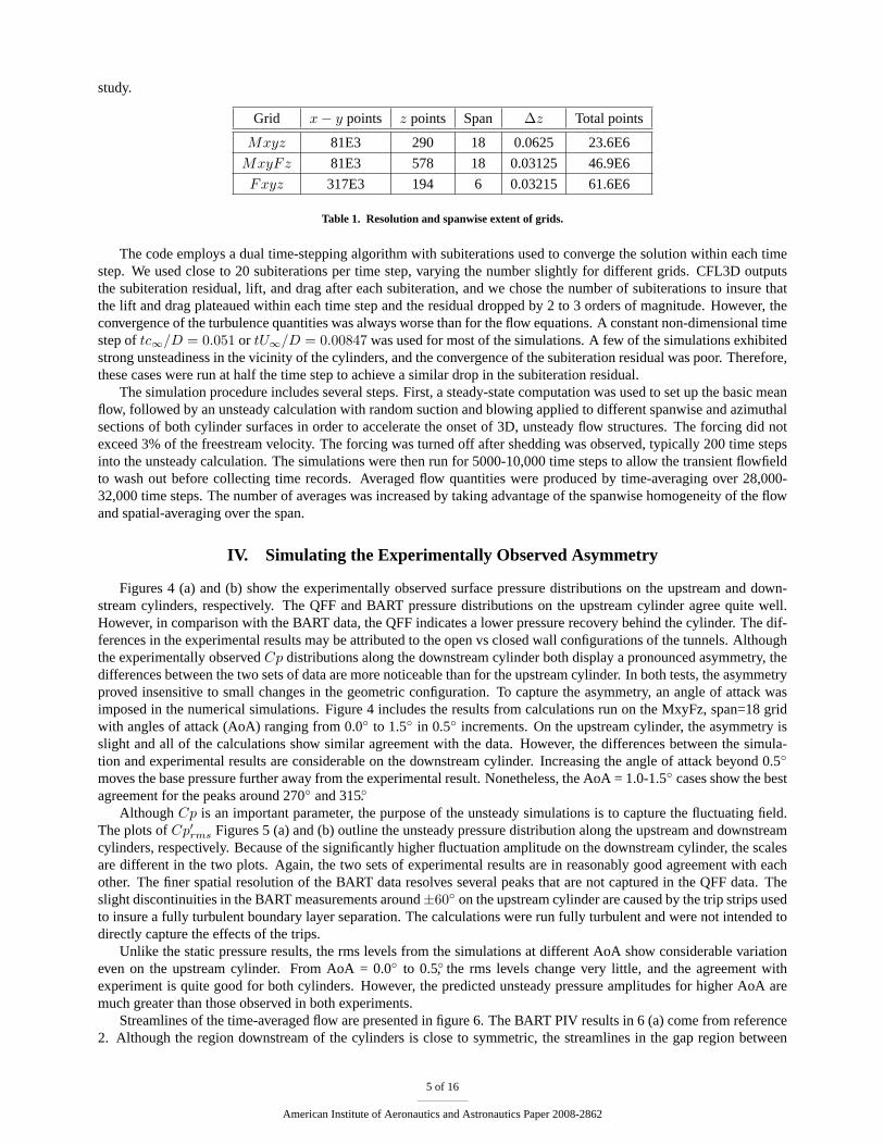
Figures 4 (a) and (b) show the experimentally observed surface pressure distributions on the upstream and down-stream cylinders, respectively. The QFF and BART pressure distributions on the upstream cylinder agree quite well.However, in comparison with the BART data, the QFF indicates a lower pressure recovery behind the cylinder. The dif-ferences in the experimental results may be attributed to the open vs closed wall configurations of the tunnels. Althoughthe experimentally observedCp distributions along the downstream cylinder both display a pronounced asymmetry, thedifferences between the two sets of data are more noticeable than for the upstream cylinder. In both tests, the asymmetryproved insensitive to small changes in the geometric configuration. To capture the asymmetry, an angle of attack wasimposed in the numerical simulations. Figure 4 includes the results from calculations run on the MxyFz, span=18 gridwith angles of attack (AoA) ranging from 0.0◦ to 1.5◦ in 0.5◦ increments. On the upstream cylinder, the asymmetry isslight and all of the calculations show similar agreement with the data. However, the differences between the simula-tion and experimental results are considerable on the downstream cylinder. Increasing the angle of attack beyond 0.5◦
moves the base pressure further away from the experimental result. Nonetheless, the AoA = 1.0-1.5◦ cases show the bestagreement for the peaks around 270◦ and 315◦.
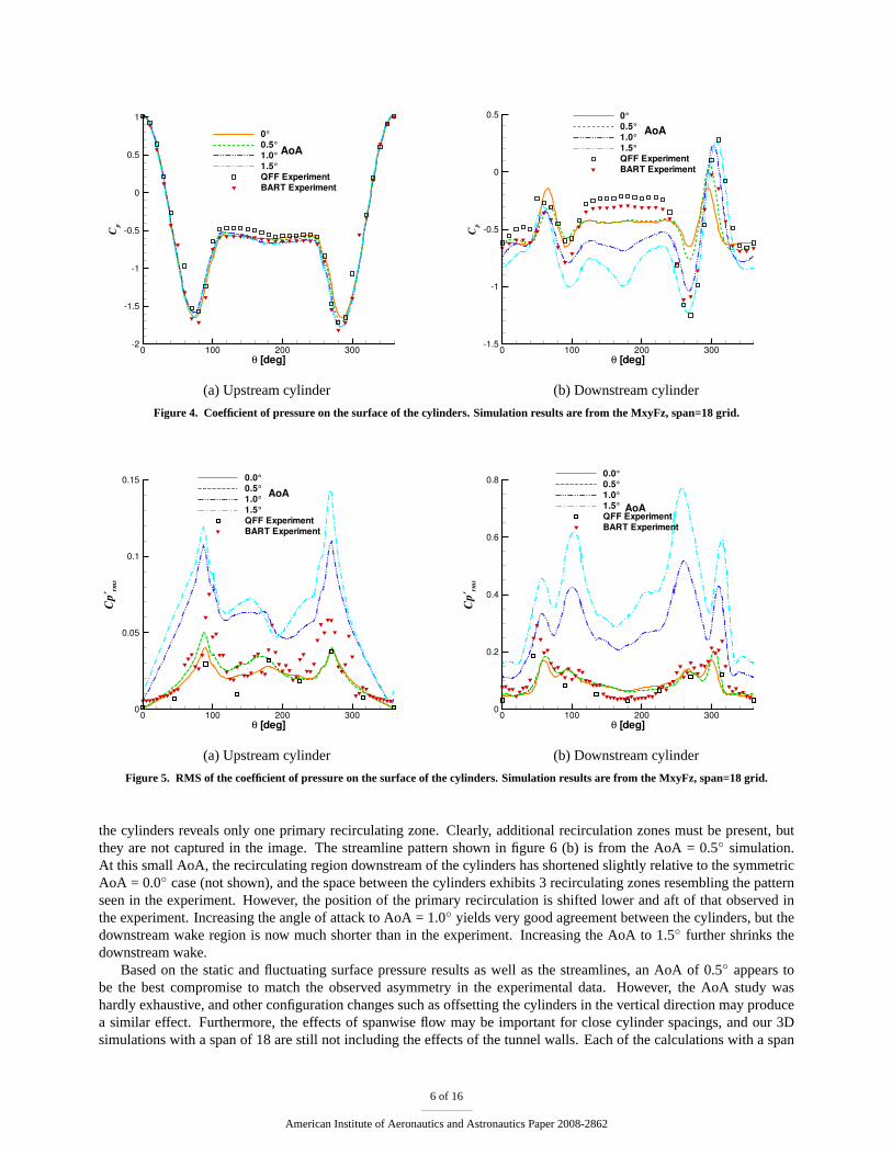
AlthoughCp is an important parameter, the purpose of the unsteady simulations is to capture the fluctuating field.The plots ofCp′rms Figures 5 (a) and (b) outline the unsteady pressure distribution along the upstream and downstreamcylinders, respectively. Because of the significantly higher fluctuation amplitude on the downstream cylinder, the scalesare different in the two plots. Again, the two sets of experimental results are in reasonably good agreement with eachother. The finer spatial resolution of the BART data resolves several peaks that are not captured in the QFF data. Theslight discontinuities in the BART measurements around±60◦ on the upstream cylinder are caused by the trip strips usedto insure a fully turbulent boundary layer separation. The calculations were run fully turbulent and were not intended todirectly capture the effects of the trips.
Unlike the static pressure results, the rms levels from the simulations at different AoA show considerable variationeven on the upstream cylinder. From AoA = 0.0◦ to 0.5◦, the rms levels change very little, and the agreement withexperiment is quite good for both cylinders. However, the predicted unsteady pressure amplitudes for higher AoA aremuch greater than those observed in both experiments.
Streamlines of the time-averaged flow are presented in figure 6. The BART PIV results in 6 (a) come from reference2. Although the region downstream of the cylinders is close to symmetric, the streamlines in the gap region between
5 of 16
American Institute of Aeronautics and Astronautics Paper 2008-2862
θ [deg]
C p
0 100 200 300-2
-1.5
-1
-0.5
0
0.5
1
0°0.5°1.0°1.5°QFF ExperimentBART Experiment
AoA
(a) Upstream cylinder
θ [deg]
C p
0 100 200 300-1.5
-1
-0.5
0
0.5 0°0.5°1.0°1.5°QFF ExperimentBART Experiment
AoA
(b) Downstream cylinder
Figure 4. Coefficient of pressure on the surface of the cylinders. Simulation results are from the MxyFz, span=18 grid.
θ [deg]
Cp′ rm
s
0 100 200 3000
0.05
0.1
0.15 0.0°0.5°1.0°1.5°QFF ExperimentBART Experiment
AoA
(a) Upstream cylinder
θ [deg]
Cp′ rm
s
0 100 200 3000
0.2
0.4
0.6
0.8 0.0°0.5°1.0°1.5°QFF ExperimentBART Experiment
AoA
(b) Downstream cylinder
Figure 5. RMS of the coefficient of pressure on the surface of the cylinders. Simulation results are from the MxyFz, span=18 grid.
the cylinders reveals only one primary recirculating zone. Clearly, additional recirculation zones must be present, butthey are not captured in the image. The streamline pattern shown in figure 6 (b) is from the AoA = 0.5◦ simulation.At this small AoA, the recirculating region downstream of the cylinders has shortened slightly relative to the symmetricAoA = 0.0◦ case (not shown), and the space between the cylinders exhibits 3 recirculating zones resembling the patternseen in the experiment. However, the position of the primary recirculation is shifted lower and aft of that observed inthe experiment. Increasing the angle of attack to AoA = 1.0◦ yields very good agreement between the cylinders, but thedownstream wake region is now much shorter than in the experiment. Increasing the AoA to 1.5◦ further shrinks thedownstream wake.
Based on the static and fluctuating surface pressure results as well as the streamlines, an AoA of 0.5◦ appears tobe the best compromise to match the observed asymmetry in the experimental data. However, the AoA study washardly exhaustive, and other configuration changes such as offsetting the cylinders in the vertical direction may producea similar effect. Furthermore, the effects of spanwise flow may be important for close cylinder spacings, and our 3Dsimulations with a span of 18 are still not including the effects of the tunnel walls. Each of the calculations with a span
6 of 16
American Institute of Aeronautics and Astronautics Paper 2008-2862
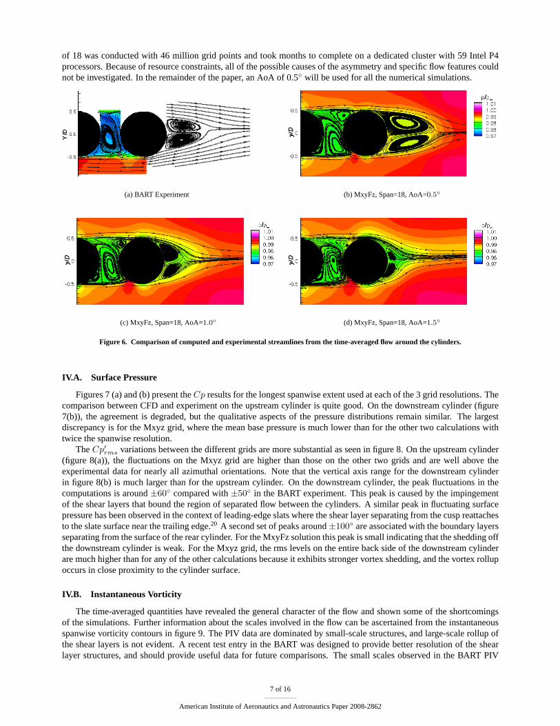
of 18 was conducted with 46 million grid points and took months to complete on a dedicated cluster with 59 Intel P4processors. Because of resource constraints, all of the possible causes of the asymmetry and specific flow features couldnot be investigated. In the remainder of the paper, an AoA of 0.5◦ will be used for all the numerical simulations.
(a) BART Experiment (b) MxyFz, Span=18, AoA=0.5◦
(c) MxyFz, Span=18, AoA=1.0◦ (d) MxyFz, Span=18, AoA=1.5◦
Figure 6. Comparison of computed and experimental streamlines from the time-averaged flow around the cylinders.
IV.A. Surface Pressure
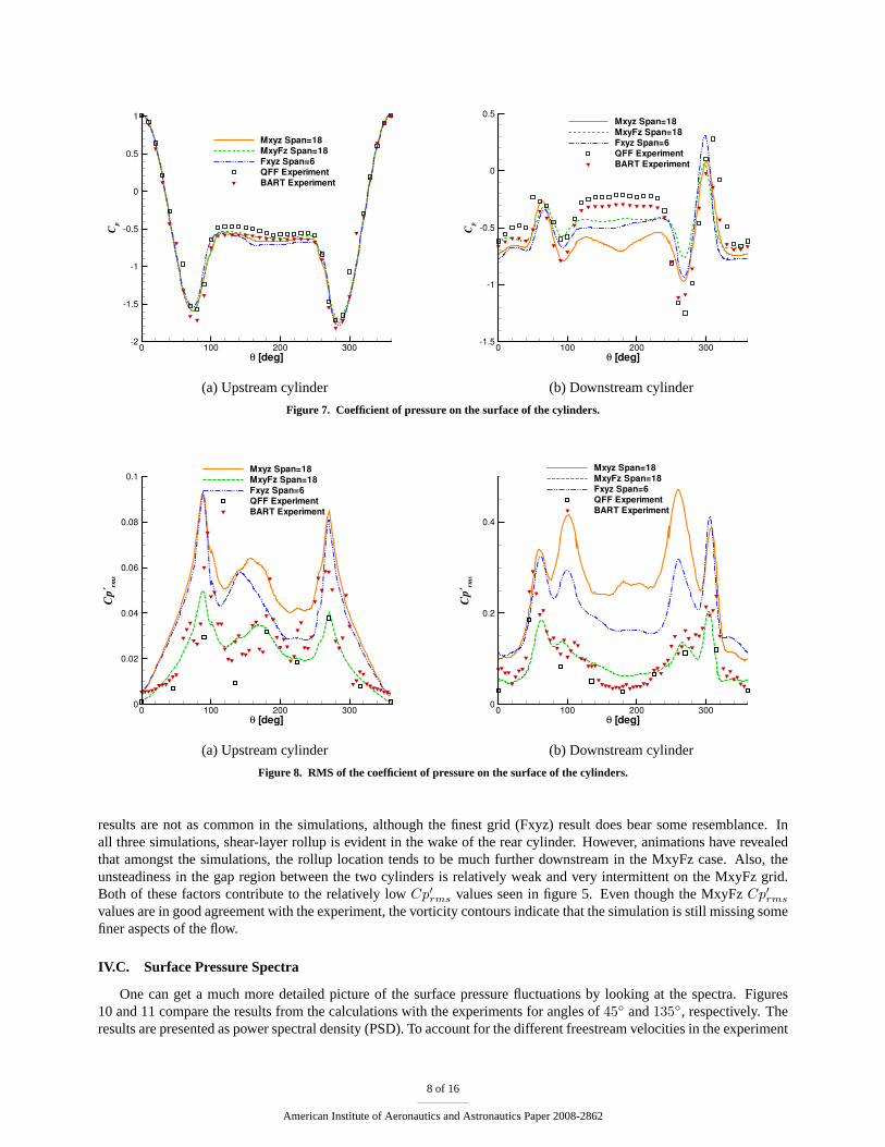
Figures 7 (a) and (b) present theCp results for the longest spanwise extent used at each of the 3 grid resolutions. Thecomparison between CFD and experiment on the upstream cylinder is quite good. On the downstream cylinder (figure7(b)), the agreement is degraded, but the qualitative aspects of the pressure distributions remain similar. The largestdiscrepancy is for the Mxyz grid, where the mean base pressure is much lower than for the other two calculations withtwice the spanwise resolution.
TheCp′rms variations between the different grids are more substantial as seen in figure 8. On the upstream cylinder(figure 8(a)), the fluctuations on the Mxyz grid are higher than those on the other two grids and are well above theexperimental data for nearly all azimuthal orientations. Note that the vertical axis range for the downstream cylinderin figure 8(b) is much larger than for the upstream cylinder. On the downstream cylinder, the peak fluctuations in thecomputations is around±60◦ compared with±50◦ in the BART experiment. This peak is caused by the impingementof the shear layers that bound the region of separated flow between the cylinders. A similar peak in fluctuating surfacepressure has been observed in the context of leading-edge slats where the shear layer separating from the cusp reattachesto the slate surface near the trailing edge.20 A second set of peaks around±100◦ are associated with the boundary layersseparating from the surface of the rear cylinder. For the MxyFz solution this peak is small indicating that the shedding offthe downstream cylinder is weak. For the Mxyz grid, the rms levels on the entire back side of the downstream cylinderare much higher than for any of the other calculations because it exhibits stronger vortex shedding, and the vortex rollupoccurs in close proximity to the cylinder surface.
IV.B. Instantaneous Vorticity
The time-averaged quantities have revealed the general character of the flow and shown some of the shortcomingsof the simulations. Further information about the scales involved in the flow can be ascertained from the instantaneousspanwise vorticity contours in figure 9. The PIV data are dominated by small-scale structures, and large-scale rollup ofthe shear layers is not evident. A recent test entry in the BART was designed to provide better resolution of the shearlayer structures, and should provide useful data for future comparisons. The small scales observed in the BART PIV
7 of 16
American Institute of Aeronautics and Astronautics Paper 2008-2862
θ [deg]
C p
0 100 200 300-2
-1.5
-1
-0.5
0
0.5
1
Mxyz Span=18MxyFz Span=18Fxyz Span=6QFF ExperimentBART Experiment
(a) Upstream cylinder
θ [deg]
C p
0 100 200 300-1.5
-1
-0.5
0
0.5Mxyz Span=18MxyFz Span=18Fxyz Span=6QFF ExperimentBART Experiment
(b) Downstream cylinder
Figure 7. Coefficient of pressure on the surface of the cylinders.
θ [deg]
Cp′ rm
s
0 100 200 3000
0.02
0.04
0.06
0.08
0.1Mxyz Span=18MxyFz Span=18Fxyz Span=6QFF ExperimentBART Experiment
(a) Upstream cylinder
θ [deg]
Cp′ rm
s
0 100 200 3000
0.2
0.4
Mxyz Span=18MxyFz Span=18Fxyz Span=6QFF ExperimentBART Experiment
(b) Downstream cylinder
Figure 8. RMS of the coefficient of pressure on the surface of the cylinders.
results are not as common in the simulations, although the finest grid (Fxyz) result does bear some resemblance. Inall three simulations, shear-layer rollup is evident in the wake of the rear cylinder. However, animations have revealedthat amongst the simulations, the rollup location tends to be much further downstream in the MxyFz case. Also, theunsteadiness in the gap region between the two cylinders is relatively weak and very intermittent on the MxyFz grid.Both of these factors contribute to the relatively lowCp′rms values seen in figure 5. Even though the MxyFzCp′rms
values are in good agreement with the experiment, the vorticity contours indicate that the simulation is still missing somefiner aspects of the flow.
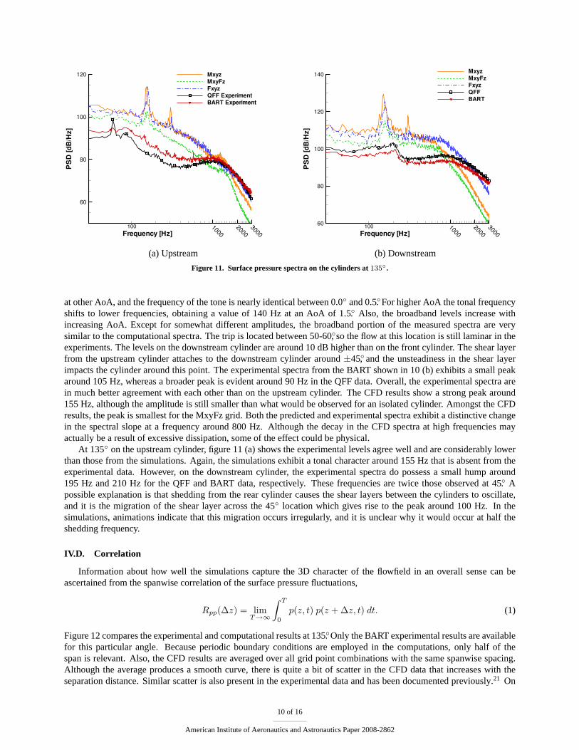
IV.C. Surface Pressure Spectra
One can get a much more detailed picture of the surface pressure fluctuations by looking at the spectra. Figures10 and 11 compare the results from the calculations with the experiments for angles of45◦ and135◦, respectively. Theresults are presented as power spectral density (PSD). To account for the different freestream velocities in the experiment
8 of 16
American Institute of Aeronautics and Astronautics Paper 2008-2862
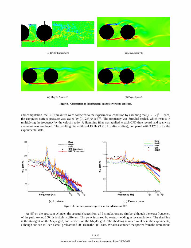
(a) BART Experiment (b) Mxyz, Span=18
(c) MxyFz, Span=18 (d) Fxyz, Span=6
Figure 9. Comparison of instantaneous spanwise vorticity contours.
and computation, the CFD pressures were corrected to the experimental condition by assuming thatp ∼ |V |2. Hence,the computed surface pressure was scaled by(0.1285/0.166)2. The frequency was Strouhal scaled, which results inmultiplying the frequency by the velocity ratio. A Hamming filter was applied to each CFD time record, and spanwiseaveraging was employed. The resulting bin width is 4.15 Hz (3.213 Hz after scaling), compared with 3.125 Hz for theexperimental data.
Frequency [Hz]
PSD
[dB/
Hz]
10002000
3000
60
80
100
120 MxyzMxyFzFxyzQFF ExperimentBART Experiment
100
(a) Upstream
Frequency [Hz]
PSD
[dB/
Hz]
10002000
300060
80
100
120
140 MxyzMxyFzFxyzQFFBART
100
(b) Downstream
Figure 10. Surface pressure spectra on the cylinders at45◦.
At 45◦ on the upstream cylinder, the spectral shapes from all 3 simulations are similar, although the exact frequencyof the peak around 150 Hz is slightly different. This peak is caused by vortex shedding in the simulations. The sheddingis the strongest on the Mxyz grid, and weakest on the MxyFz grid. The shedding is much weaker in the experiments,although one can still see a small peak around 200 Hz in the QFF data. We also examined the spectra from the simulations
9 of 16
American Institute of Aeronautics and Astronautics Paper 2008-2862
Frequency [Hz]
PSD
[dB/
Hz]
10002000
3000
60
80
100
120 MxyzMxyFzFxyzQFF ExperimentBART Experiment
100
(a) Upstream
Frequency [Hz]
PSD
[dB/
Hz]
10002000
300060
80
100
120
140 MxyzMxyFzFxyzQFFBART
100
(b) Downstream
Figure 11. Surface pressure spectra on the cylinders at135◦.
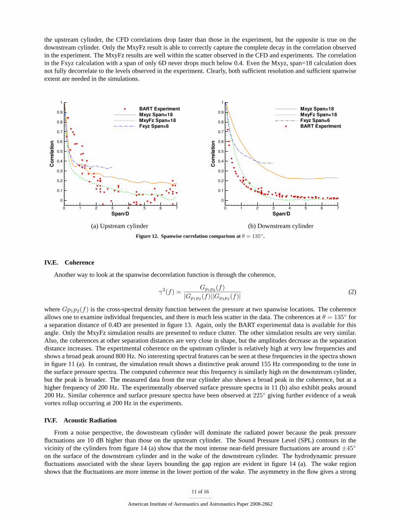
at other AoA, and the frequency of the tone is nearly identical between 0.0◦ and 0.5◦. For higher AoA the tonal frequencyshifts to lower frequencies, obtaining a value of 140 Hz at an AoA of 1.5◦. Also, the broadband levels increase withincreasing AoA. Except for somewhat different amplitudes, the broadband portion of the measured spectra are verysimilar to the computational spectra. The trip is located between 50-60◦, so the flow at this location is still laminar in theexperiments. The levels on the downstream cylinder are around 10 dB higher than on the front cylinder. The shear layerfrom the upstream cylinder attaches to the downstream cylinder around±45◦, and the unsteadiness in the shear layerimpacts the cylinder around this point. The experimental spectra from the BART shown in 10 (b) exhibits a small peakaround 105 Hz, whereas a broader peak is evident around 90 Hz in the QFF data. Overall, the experimental spectra arein much better agreement with each other than on the upstream cylinder. The CFD results show a strong peak around155 Hz, although the amplitude is still smaller than what would be observed for an isolated cylinder. Amongst the CFDresults, the peak is smallest for the MxyFz grid. Both the predicted and experimental spectra exhibit a distinctive changein the spectral slope at a frequency around 800 Hz. Although the decay in the CFD spectra at high frequencies mayactually be a result of excessive dissipation, some of the effect could be physical.
At 135◦ on the upstream cylinder, figure 11 (a) shows the experimental levels agree well and are considerably lowerthan those from the simulations. Again, the simulations exhibit a tonal character around 155 Hz that is absent from theexperimental data. However, on the downstream cylinder, the experimental spectra do possess a small hump around195 Hz and 210 Hz for the QFF and BART data, respectively. These frequencies are twice those observed at 45◦. Apossible explanation is that shedding from the rear cylinder causes the shear layers between the cylinders to oscillate,and it is the migration of the shear layer across the 45◦ location which gives rise to the peak around 100 Hz. In thesimulations, animations indicate that this migration occurs irregularly, and it is unclear why it would occur at half theshedding frequency.
IV.D. Correlation
Information about how well the simulations capture the 3D character of the flowfield in an overall sense can beascertained from the spanwise correlation of the surface pressure fluctuations,
Rpp(∆z) = limT→∞
∫ T
0
p(z, t) p(z + ∆z, t) dt. (1)
Figure 12 compares the experimental and computational results at 135◦. Only the BART experimental results are availablefor this particular angle. Because periodic boundary conditions are employed in the computations, only half of thespan is relevant. Also, the CFD results are averaged over all grid point combinations with the same spanwise spacing.Although the average produces a smooth curve, there is quite a bit of scatter in the CFD data that increases with theseparation distance. Similar scatter is also present in the experimental data and has been documented previously.21 On
10 of 16
American Institute of Aeronautics and Astronautics Paper 2008-2862
the upstream cylinder, the CFD correlations drop faster than those in the experiment, but the opposite is true on thedownstream cylinder. Only the MxyFz result is able to correctly capture the complete decay in the correlation observedin the experiment. The MxyFz results are well within the scatter observed in the CFD and experiments. The correlationin the Fxyz calculation with a span of only 6D never drops much below 0.4. Even the Mxyz, span=18 calculation doesnot fully decorrelate to the levels observed in the experiment. Clearly, both sufficient resolution and sufficient spanwiseextent are needed in the simulations.
Span/D
Corre
latio
n
0 1 2 3 4 5 6 7
0
0.1
0.2
0.3
0.4
0.5
0.6
0.7
0.8
0.9
1BART ExperimentMxyz Span=18MxyFz Span=18Fxyz Span=6
(a) Upstream cylinder
Span/DCo
rrela
tion
0 1 2 3 4 5 6 7
0
0.1
0.2
0.3
0.4
0.5
0.6
0.7
0.8
0.9
1Mxyz Span=18MxyFz Span=18Fxyz Span=6BART Experiment
(b) Downstream cylinder
Figure 12. Spanwise correlation comparison atθ = 135◦.
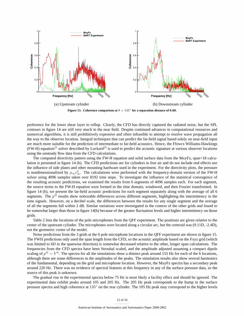
IV.E. Coherence
Another way to look at the spanwise decorrelation function is through the coherence,
γ2(f) =Gp1p2(f)
|Gp1p2(f)||Gp2p2(f)|(2)
whereGp1p2(f) is the cross-spectral density function between the pressure at two spanwise locations. The coherenceallows one to examine individual frequencies, and there is much less scatter in the data. The coherences atθ = 135◦ fora separation distance of 0.4D are presented in figure 13. Again, only the BART experimental data is available for thisangle. Only the MxyFz simulation results are presented to reduce clutter. The other simulation results are very similar.Also, the coherences at other separation distances are very close in shape, but the amplitudes decrease as the separationdistance increases. The experimental coherence on the upstream cylinder is relatively high at very low frequencies andshows a broad peak around 800 Hz. No interesting spectral features can be seen at these frequencies in the spectra shownin figure 11 (a). In contrast, the simulation result shows a distinctive peak around 155 Hz corresponding to the tone inthe surface pressure spectra. The computed coherence near this frequency is similarly high on the downstream cylinder,but the peak is broader. The measured data from the rear cylinder also shows a broad peak in the coherence, but at ahigher frequency of 200 Hz. The experimentally observed surface pressure spectra in 11 (b) also exhibit peaks around200 Hz. Similar coherence and surface pressure spectra have been observed at225◦ giving further evidence of a weakvortex rollup occurring at 200 Hz in the experiments.
IV.F. Acoustic Radiation
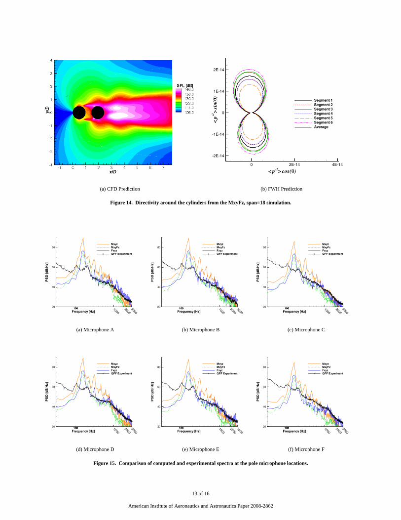
From a noise perspective, the downstream cylinder will dominate the radiated power because the peak pressurefluctuations are 10 dB higher than those on the upstream cylinder. The Sound Pressure Level (SPL) contours in thevicinity of the cylinders from figure 14 (a) show that the most intense near-field pressure fluctuations are around±45◦
on the surface of the downstream cylinder and in the wake of the downstream cylinder. The hydrodynamic pressurefluctuations associated with the shear layers bounding the gap region are evident in figure 14 (a). The wake regionshows that the fluctuations are more intense in the lower portion of the wake. The asymmetry in the flow gives a strong
11 of 16
American Institute of Aeronautics and Astronautics Paper 2008-2862
Frequency [Hz]
Cohe
renc
e
10002000
30000
0.2
0.4
0.6
0.8
1 MxyFzBART Experiment
(a) Upstream cylinder
Frequency [Hz]
Cohe
renc
e
10002000
30000
0.2
0.4
0.6
0.8
1
MxyFzBART Experiment
(b) Downstream cylinder
Figure 13. Coherence comparison atθ = 135◦ for a separation distance of 0.4D.
preference for the lower shear layer to rollup. Clearly, the CFD has directly captured the radiated noise, but the SPLcontours in figure 14 are still very much in the near field. Despite continued advances in computational resources andnumerical algorithms, it is still prohibitively expensive and often infeasible to attempt to resolve wave propagation allthe way to the observer location. Integral techniques that can predict the far-field signal based solely on near-field inputare much more suitable for the prediction of intermediate to far-field acoustics. Hence, the Ffowcs Williams-Hawkings(FW-H) equation22 solver described by Lockard23 is used to predict the acoustic signature at various observer locationsusing the unsteady flow data from the CFD calculations.
The computed directivity pattern using the FW-H equation and solid surface data from the MxyFz, span=18 calcu-lation is presented in figure 14 (b). The CFD predictions are for cylinders in free air and do not include end effects northe influence of side plates and other mounting hardware used in the experiment. For the directivity plots, the pressureis nondimensionalized byρ∞c2
∞. The calculations were performed with the frequency-domain version of the FW-Hsolver using 4096 samples taken over 8192 time steps. To investigate the influence of the statistical convergence ofthe resulting acoustic predictions, we examined the results from 6 segments of 4096 samples each. For each segment,the source terms to the FW-H equation were formed in the time domain, windowed, and then Fourier transformed. Infigure 14 (b), we present the far-field acoustic predictions for each segment separately along with the average of all 6segments. Thep′2 results show noticeable differences across different segments, highlighting the intermittency in thetime signals. However, on a decibel scale, the differences between the results for any single segment and the averageof all the segments fall within 2 dB. Similar variations were investigated in the context of the other grids and found tobe somewhat larger than those in figure 14(b) because of the greater fluctuation levels and higher intermittency on thosegrids.
Table 2 lists the locations of the pole microphones from the QFF experiment. The positions are given relative to thecenter of the upstream cylinder. The microphones were located along a circular arc, but the centroid was (9.11D, -2.4D),not the geometric center of the model.
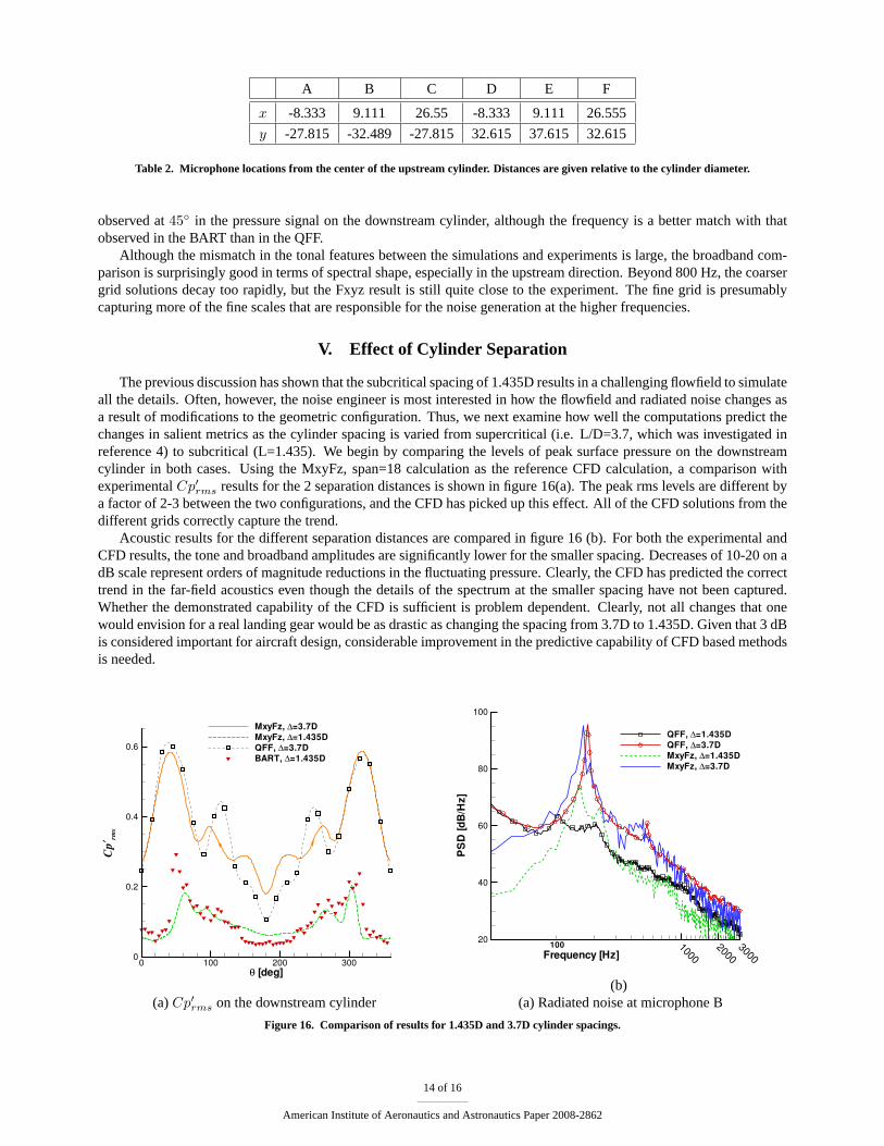
Noise predictions from the 3 grids at the 6 pole microphone locations in the QFF experiment are shown in figure 15.The FWH predictions only used the span length from the CFD, so the acoustic amplitude based on the Fxyz grid (whichwas limited to 6D in the spanwise direction) is somewhat decreased relative to the other, longer span calculations. Thefrequencies from the CFD spectra have been Strouhal scaled, and the amplitude adjusted assuming a compact dipolescaling ofp′2 ∼ V 6. The spectra for all the simulations show a distinct peak around 155 Hz for each of the 6 locations,although there are some differences in the amplitudes of the peaks. The simulation results also show several harmonicsof the fundamental, depending on the grid and microphone location. However, the MxyFz spectra has a secondary peakaround 220 Hz. There was no evidence of spectral features at this frequency in any of the surface pressure data, so thesource of this peak is unknown.
The gradual rise in the experimental spectra below 75 Hz is most likely a facility effect and should be ignored. Theexperimental data exhibit peaks around 105 and 205 Hz. The 205 Hz peak corresponds to the hump in the surfacepressure spectra and high coherence at135◦ on the rear cylinder. The 105 Hz peak may correspond to the higher levels
12 of 16
American Institute of Aeronautics and Astronautics Paper 2008-2862
(a) CFD Prediction
< p′2> cos(θ)
<p′2 >s
in(θ
)
0 2E-14 4E-14
-2E-14
-1E-14
0
1E-14
2E-14
Segment 1Segment 2Segment 3Segment 4Segment 5Segment 6Average
(b) FWH Prediction
Figure 14. Directivity around the cylinders from the MxyFz, span=18 simulation.
Frequency [Hz]
PSD
[dB/
Hz]
10002000
300020
40
60
80MxyzMxyFzFxyzQFF Experiment
100100
(a) Microphone A
Frequency [Hz]
PSD
[dB/
Hz]
10002000
300020
40
60
80MxyzMxyFzFxyzQFF Experiment
100100
(b) Microphone B
Frequency [Hz]
PSD
[dB/
Hz]
10002000
300020
40
60
80MxyzMxyFzFxyzQFF Experiment
100100
(c) Microphone C
Frequency [Hz]
PSD
[dB/
Hz]
10002000
300020
40
60
80MxyzMxyFzFxyzQFF Experiment
100100
(d) Microphone D
Frequency [Hz]
PSD
[dB/
Hz]
10002000
300020
40
60
80MxyzMxyFzFxyzQFF Experiment
100100
(e) Microphone E
Frequency [Hz]
PSD
[dB/
Hz]
10002000
300020
40
60
80MxyzMxyFzFxyzQFF Experiment
100100
(f) Microphone F
Figure 15. Comparison of computed and experimental spectra at the pole microphone locations.
13 of 16
American Institute of Aeronautics and Astronautics Paper 2008-2862
A B C D E F
x -8.333 9.111 26.55 -8.333 9.111 26.555
y -27.815 -32.489 -27.815 32.615 37.615 32.615
Table 2. Microphone locations from the center of the upstream cylinder. Distances are given relative to the cylinder diameter.
observed at45◦ in the pressure signal on the downstream cylinder, although the frequency is a better match with thatobserved in the BART than in the QFF.
Although the mismatch in the tonal features between the simulations and experiments is large, the broadband com-parison is surprisingly good in terms of spectral shape, especially in the upstream direction. Beyond 800 Hz, the coarsergrid solutions decay too rapidly, but the Fxyz result is still quite close to the experiment. The fine grid is presumablycapturing more of the fine scales that are responsible for the noise generation at the higher frequencies.
V. Effect of Cylinder Separation
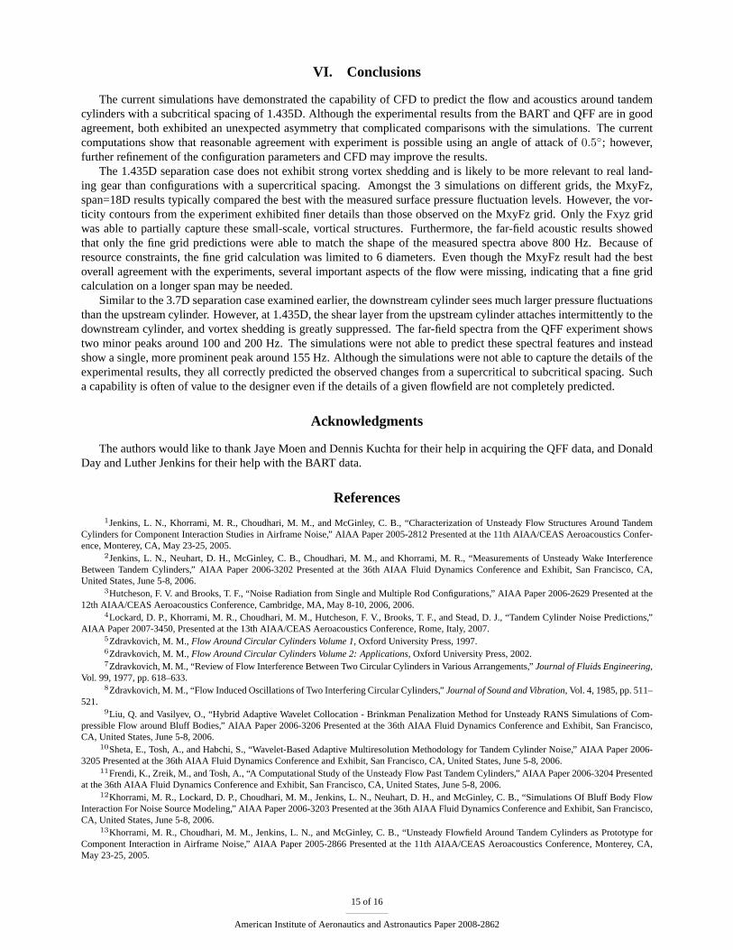
The previous discussion has shown that the subcritical spacing of 1.435D results in a challenging flowfield to simulateall the details. Often, however, the noise engineer is most interested in how the flowfield and radiated noise changes asa result of modifications to the geometric configuration. Thus, we next examine how well the computations predict thechanges in salient metrics as the cylinder spacing is varied from supercritical (i.e. L/D=3.7, which was investigated inreference 4) to subcritical (L=1.435). We begin by comparing the levels of peak surface pressure on the downstreamcylinder in both cases. Using the MxyFz, span=18 calculation as the reference CFD calculation, a comparison withexperimentalCp′rms results for the 2 separation distances is shown in figure 16(a). The peak rms levels are different bya factor of 2-3 between the two configurations, and the CFD has picked up this effect. All of the CFD solutions from thedifferent grids correctly capture the trend.
Acoustic results for the different separation distances are compared in figure 16 (b). For both the experimental andCFD results, the tone and broadband amplitudes are significantly lower for the smaller spacing. Decreases of 10-20 on adB scale represent orders of magnitude reductions in the fluctuating pressure. Clearly, the CFD has predicted the correcttrend in the far-field acoustics even though the details of the spectrum at the smaller spacing have not been captured.Whether the demonstrated capability of the CFD is sufficient is problem dependent. Clearly, not all changes that onewould envision for a real landing gear would be as drastic as changing the spacing from 3.7D to 1.435D. Given that 3 dBis considered important for aircraft design, considerable improvement in the predictive capability of CFD based methodsis needed.
θ [deg]
Cp′ rm
s
0 100 200 3000
0.2
0.4
0.6
MxyFz, ∆=3.7DMxyFz, ∆=1.435DQFF, ∆=3.7DBART, ∆=1.435D
(a)Cp′rms on the downstream cylinder
Frequency [Hz]
PSD
[dB/
Hz]
10002000
300020
40
60
80
100
QFF, ∆=1.435DQFF, ∆=3.7DMxyFz, ∆=1.435DMxyFz, ∆=3.7D
100
(b)(a) Radiated noise at microphone B
Figure 16. Comparison of results for 1.435D and 3.7D cylinder spacings.
14 of 16
American Institute of Aeronautics and Astronautics Paper 2008-2862
VI. Conclusions
The current simulations have demonstrated the capability of CFD to predict the flow and acoustics around tandemcylinders with a subcritical spacing of 1.435D. Although the experimental results from the BART and QFF are in goodagreement, both exhibited an unexpected asymmetry that complicated comparisons with the simulations. The currentcomputations show that reasonable agreement with experiment is possible using an angle of attack of0.5◦; however,further refinement of the configuration parameters and CFD may improve the results.
The 1.435D separation case does not exhibit strong vortex shedding and is likely to be more relevant to real land-ing gear than configurations with a supercritical spacing. Amongst the 3 simulations on different grids, the MxyFz,span=18D results typically compared the best with the measured surface pressure fluctuation levels. However, the vor-ticity contours from the experiment exhibited finer details than those observed on the MxyFz grid. Only the Fxyz gridwas able to partially capture these small-scale, vortical structures. Furthermore, the far-field acoustic results showedthat only the fine grid predictions were able to match the shape of the measured spectra above 800 Hz. Because ofresource constraints, the fine grid calculation was limited to 6 diameters. Even though the MxyFz result had the bestoverall agreement with the experiments, several important aspects of the flow were missing, indicating that a fine gridcalculation on a longer span may be needed.
Similar to the 3.7D separation case examined earlier, the downstream cylinder sees much larger pressure fluctuationsthan the upstream cylinder. However, at 1.435D, the shear layer from the upstream cylinder attaches intermittently to thedownstream cylinder, and vortex shedding is greatly suppressed. The far-field spectra from the QFF experiment showstwo minor peaks around 100 and 200 Hz. The simulations were not able to predict these spectral features and insteadshow a single, more prominent peak around 155 Hz. Although the simulations were not able to capture the details of theexperimental results, they all correctly predicted the observed changes from a supercritical to subcritical spacing. Sucha capability is often of value to the designer even if the details of a given flowfield are not completely predicted.
Acknowledgments
The authors would like to thank Jaye Moen and Dennis Kuchta for their help in acquiring the QFF data, and DonaldDay and Luther Jenkins for their help with the BART data.
References1Jenkins, L. N., Khorrami, M. R., Choudhari, M. M., and McGinley, C. B., “Characterization of Unsteady Flow Structures Around Tandem
Cylinders for Component Interaction Studies in Airframe Noise,” AIAA Paper 2005-2812 Presented at the 11th AIAA/CEAS Aeroacoustics Confer-ence, Monterey, CA, May 23-25, 2005.
2Jenkins, L. N., Neuhart, D. H., McGinley, C. B., Choudhari, M. M., and Khorrami, M. R., “Measurements of Unsteady Wake InterferenceBetween Tandem Cylinders,” AIAA Paper 2006-3202 Presented at the 36th AIAA Fluid Dynamics Conference and Exhibit, San Francisco, CA,United States, June 5-8, 2006.
3Hutcheson, F. V. and Brooks, T. F., “Noise Radiation from Single and Multiple Rod Configurations,” AIAA Paper 2006-2629 Presented at the12th AIAA/CEAS Aeroacoustics Conference, Cambridge, MA, May 8-10, 2006, 2006.
4Lockard, D. P., Khorrami, M. R., Choudhari, M. M., Hutcheson, F. V., Brooks, T. F., and Stead, D. J., “Tandem Cylinder Noise Predictions,”AIAA Paper 2007-3450, Presented at the 13th AIAA/CEAS Aeroacoustics Conference, Rome, Italy, 2007.
5Zdravkovich, M. M.,Flow Around Circular Cylinders Volume 1, Oxford University Press, 1997.6Zdravkovich, M. M.,Flow Around Circular Cylinders Volume 2: Applications, Oxford University Press, 2002.7Zdravkovich, M. M., “Review of Flow Interference Between Two Circular Cylinders in Various Arrangements,”Journal of Fluids Engineering,
Vol. 99, 1977, pp. 618–633.8Zdravkovich, M. M., “Flow Induced Oscillations of Two Interfering Circular Cylinders,”Journal of Sound and Vibration, Vol. 4, 1985, pp. 511–
521.9Liu, Q. and Vasilyev, O., “Hybrid Adaptive Wavelet Collocation - Brinkman Penalization Method for Unsteady RANS Simulations of Com-
pressible Flow around Bluff Bodies,” AIAA Paper 2006-3206 Presented at the 36th AIAA Fluid Dynamics Conference and Exhibit, San Francisco,CA, United States, June 5-8, 2006.
10Sheta, E., Tosh, A., and Habchi, S., “Wavelet-Based Adaptive Multiresolution Methodology for Tandem Cylinder Noise,” AIAA Paper 2006-3205 Presented at the 36th AIAA Fluid Dynamics Conference and Exhibit, San Francisco, CA, United States, June 5-8, 2006.
11Frendi, K., Zreik, M., and Tosh, A., “A Computational Study of the Unsteady Flow Past Tandem Cylinders,” AIAA Paper 2006-3204 Presentedat the 36th AIAA Fluid Dynamics Conference and Exhibit, San Francisco, CA, United States, June 5-8, 2006.
12Khorrami, M. R., Lockard, D. P., Choudhari, M. M., Jenkins, L. N., Neuhart, D. H., and McGinley, C. B., “Simulations Of Bluff Body FlowInteraction For Noise Source Modeling,” AIAA Paper 2006-3203 Presented at the 36th AIAA Fluid Dynamics Conference and Exhibit, San Francisco,CA, United States, June 5-8, 2006.
13Khorrami, M. R., Choudhari, M. M., Jenkins, L. N., and McGinley, C. B., “Unsteady Flowfield Around Tandem Cylinders as Prototype forComponent Interaction in Airframe Noise,” AIAA Paper 2005-2866 Presented at the 11th AIAA/CEAS Aeroacoustics Conference, Monterey, CA,May 23-25, 2005.
15 of 16
American Institute of Aeronautics and Astronautics Paper 2008-2862
14Khorrami, M. R., Choudhari, M. M., Lockard, D. P., Jenkins, L. N., and McGinley, C. B., “Unsteady Flowfield Around Tandem Cylinders asPrototype for Component Interaction in Airframe Noise,”AIAA Journal, Vol. 45, No. 8, 2007, pp. 1930–1941.
15Menter, F. R., “Two-equation Eddy-viscosity Turbulence Models for Engineering Applications,”AIAA Journal, Vol. 32, No. 8, 1994, pp. 1598–1605.
16Roshko, A., “Experiments On The Flow Past A Circular Cylinder At Very High Reynolds Number,”Journal of Fluid Mechanics, Vol. 10, 1961,pp. 345–356.
17Rumsey, C. L., Biedron, R. T., and Thomas, J. L., “CFL3D: Its History and Some Recent Applications,” NASA TM 112861, May 1997,presented at the Godonov’s Method for Gas Dynamics Symposium, Ann Arbor, MI.
18Krist, S. L., Biedron, R. T., and Rumsey, C. L., “CFL3D User’s Manual (Version 5),” NASA TM 208444, NASA Langley Research Center:Computational Aerosciences Branch, 1997.
19Menter, F. R., “Zonal Two-equation k-w Turbulence Models for Aerodynamic Flows,” AIAA Paper 1993-2906, 1993.20Choudhari, M. M. and Khorrami, M. R., “Effect of Three-Dimensional Shear-Layer Structures on Slat Cove Unsteadiness,”AIAA Journal,
Vol. 45, No. 9, 2007, pp. 2174–2186.21Szepessy, S., “On the Spanwise Correlation of Vortex Shedding from a Circular Cylinder at High Subcritical Reynolds Number,”Physics of
Fluids, Vol. 6, No. 7, 1994, pp. 2406–2416.22Ffowcs Williams, J. E. and Hawkings, D. L., “Sound generation by turbulence and surfaces in arbitrary motion,”Philosophical Transactions of
the Royal Society of London A, Vol. 342, 1969, pp. 264–321.23Lockard, D. P., “A Comparison of Ffowcs Williams-Hawkings Solvers for Airframe Noise Applications,” AIAA Paper 2002-2580, 8th
AIAA/CEAS Aeroacoustics Conference, Breckenridge, CO, June 17–19, 2002.
16 of 16
American Institute of Aeronautics and Astronautics Paper 2008-2862