Embed Size (px)
Citation preview

© 2003 Bruker AXS All Rights Reserved
Advances in X-Ray ScintillatorTechnology
Roger D. Durst
Bruker AXS Inc.
Bruker AXS© 2003 Bruker AXS All Rights Reserved
Acknowledgements
?T. Thorson, Bruker AXS
?Y. Diawara, Bruker AXS
?E. Westbrook, MBC
?J. Morse, ESRF
?C. Summers, Georgia Tech/PTCE
?B. Wagner, Georgia Tech/PTCE
?V. Valdna, TTU
?Supported in part by NIH RO1 RR16334
Bruker AXS© 2003 Bruker AXS All Rights Reserved
Scintillator-based imagers
?One of the earliest techniques employed for imaging ionizing radiation
?Scintillator-based imagers remain one of the most flexible and successful techniques for x-ray imaging? Crystallography? SAXS/WAXS? Microtomography...
?However, conventional scintillators have significant limitations...

Bruker AXS© 2003 Bruker AXS All Rights Reserved
Limitations of conventional scintillators: point spread function
?Point Spread Function (PSF) is limited by scattering in polycrystalline phosphor screen: typically > 100 ?m FWHM
x-ray
scintillator screen
point spread

Bruker AXS© 2003 Bruker AXS All Rights Reserved
Limitations of conventional scintillators:Light loss in demagnifying optics
?Conventional screens are Lambertian
?However, light emitted at large angles is lost in the optics
?Only low angle light is transmitted to CCD
high angle lightlost in fiber optic
only low angle lighttransmitted to CCD

Bruker AXS© 2003 Bruker AXS All Rights Reserved
Transmission efficiency scales as 1/m2
m=2, T=12% m=3, T=6% m=5, T=2%

Bruker AXS© 2003 Bruker AXS All Rights Reserved
Present day integrating detectors do not achieve optimal sensitivity
?Gruner (1996) noted that for optimal dynamic range and near-quantum limited performance an integrating detector (CCD, a-Se, …) should achieve a SNR of order 1.
?Because of transmission losses and point spread, no present large area, integrating detectors satisfy this criterion...
CCD (typical) a-Se (typical)Quantum gain 10 electrons 120 electronsNoise 10 electrons 500 electronsIntegrated noise 40 electrons 500 electronsTrue SNR 0.25 0.25
Bruker AXS© 2003 Bruker AXS All Rights Reserved
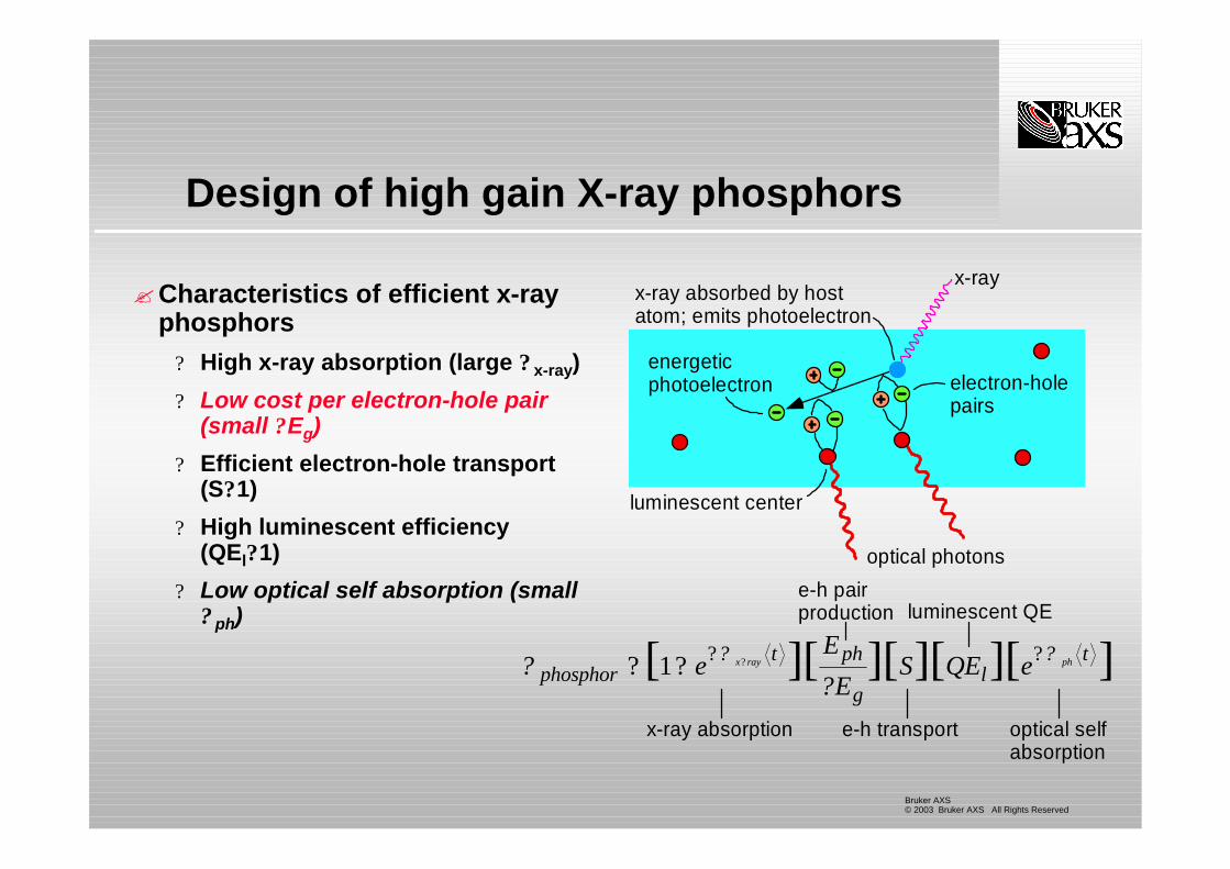
Design of high gain X-ray phosphors
?Characteristics of efficient x-ray phosphors
? High x-ray absorption (large ? x-ray)
? Low cost per electron-hole pair (small ?Eg)
? Efficient electron-hole transport (S?1)
? High luminescent efficiency (QEl?1)
? Low optical self absorption (small ? ph)
??
? ?phosphor
t ph
gl
teE
ES QE ex ray ph? ? ? ??[ ][ ][ ][ ][ ]1
x-ray absorption
e-h pairproduction
e-h transport
luminescent QE
optical selfabsorption
energeticphotoelectron
luminescent center
electron-holepairs
x-ray absorbed by hostatom; emits photoelectron
x-ray
optical photons

Bruker AXS© 2003 Bruker AXS All Rights Reserved
Development of high gain x-ray phosphors
•ZnSe:Cu,Ce has the highest known x-ray conversion efficiency-Three times higher than Gd2O2S:Tb-Status: commercially available-However, not suitable for MAD phasing because of Se edge
•ZnTe under development for macromolecular applications*-Collaboration with MBC, Georgia Tech, TTU.-Efficiency potentially comparable to ZnSe-No Se edge, suitable for MAD experiments
Eg (eV) Eeh (eV) Gain(photons/x-ray)
ZnTe 2.3 5.0 2,400ZnSe 2.7 5.9 2,040ZnS 3.8 11.0 1,040CsI 6.4 16.0 755Gd2O2S 4.4 17.2 700CaWO4 4.6 32.2 370

Bruker AXS© 2003 Bruker AXS All Rights Reserved
Design of high resolution scintillators:Thin film phosphors
?Very high spatial resolution possible using thin film scintillators? Thin (~15 ? m) solid film deposited
on glass substrate? No scattering, thus better PSF
(e.g., Koch 2000)
?However, solid scintillating films are inefficient? Typically >90% of light is trapped
in screen by total internal reflection
? <10% of light is emitted
?Thin film scintillators give high resolution but poor sensitivity
lens
no light scatteringin thin film scintillator
x-ray

Bruker AXS© 2003 Bruker AXS All Rights Reserved
Ideally, scintillator emission should be forward peaked
?Allows more efficient coupling to optics
?Prevents trapping by total internal reflection
?How could such a screen be realized?
acceptanceconeacceptanceconeacceptanceconeacceptancecone
Bruker AXS© 2003 Bruker AXS All Rights Reserved
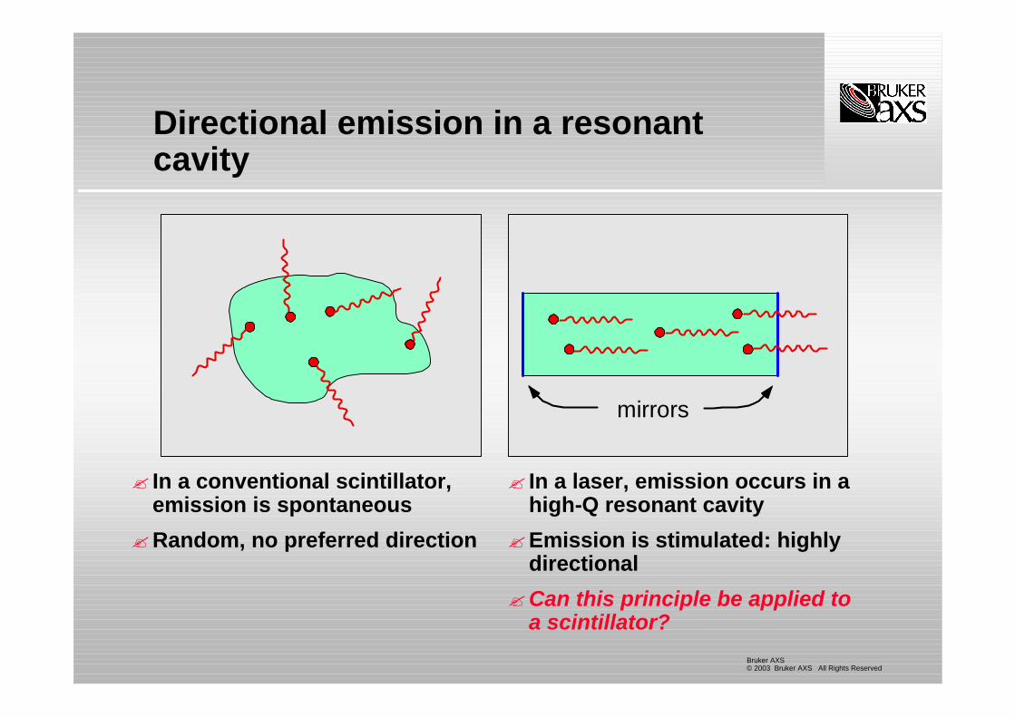
Directional emission in a resonant cavity
? In a conventional scintillator, emission is spontaneous
?Random, no preferred direction
? In a laser, emission occurs in a high-Q resonant cavity
?Emission is stimulated: highly directional
?Can this principle be applied to a scintillator?
mirrors

Bruker AXS© 2003 Bruker AXS All Rights Reserved
Quantum Resonance Convertor (QRC)*
?Phosphor deposited between mirrors
?Mirror x-ray transparent? Low-Z dielectric stack
?Phosphor layer must be sufficiently thick so as to absorb incident x-rays? >12 ? m for Gd2O2S, 8 keV
?Vacuum deposited on substrate? glass? fiber optic faceplate
*Patents pending
substrate
front mirror
phosphor
back mirror
x-rays

Bruker AXS© 2003 Bruker AXS All Rights Reserved
QRC vs laser
?QRC and laser have similar structures, however QRC is not a laser? There is no gain medium (I.e., no population inversion)? There is no amplification in a QRC, the same number of photons
are emitted but the angular distribution of the emitted light ismodified
?In a conventional scintillator, emission probability is isotropic
?In QRC, emission is strongly peaked due to interference? Resonant modes (forward peaked) enhanced? Non-resonant modes (high angle) suppressed
? ? ? ????n
iTi iREren )??(d)(ˆ2W n
2
2n?
??

Bruker AXS© 2003 Bruker AXS All Rights Reserved
QRC prototypes
?Prototype QRC screens up to 220 mm diagonal have been produced to date
220 mm
Bruker AXS© 2003 Bruker AXS All Rights Reserved
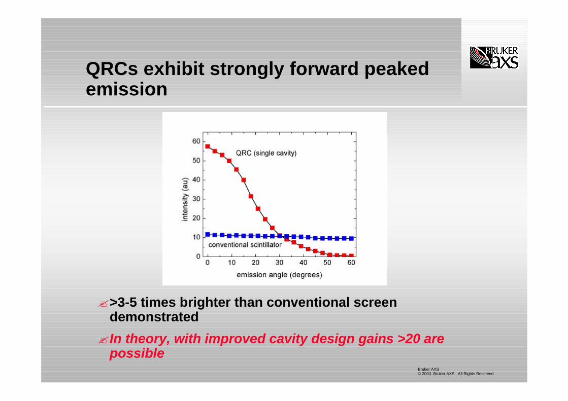
QRCs exhibit strongly forward peaked emission
?>3-5 times brighter than conventional screen demonstrated
?In theory, with improved cavity design gains >20 are possible

Bruker AXS© 2003 Bruker AXS All Rights Reserved
QRC spatial resolution
?No scattering in screen allows high spatial resolution
?PSF < 20 microns: 5 times better than conventional phosphor screen
Pattern generated by 10 micron e-beam on QRC

Bruker AXS© 2003 Bruker AXS All Rights Reserved
Application of QRCs:Fiber optic coupled CCDs
?QRC screens will be back compatible with new and existing fiber optic cameras? Multilayer deposited on fiber
optic faceplate
?Simple field upgrade? Improved sensitivity (est.
>3X)? Improved point spread
function (est. >4X)

Bruker AXS© 2003 Bruker AXS All Rights Reserved
Application of QRCs:Advanced lens-coupled cameras
?Forwarded-peaked emission from QRC couples more efficiently to lens optics as well
?Lens-coupled QRC? large active area? very high sensitivity? high resolution? relatively low cost
?Especially suitable for high speed CCDs? Eg., Frelon camera…
200 mm active arealens-coupled detector

Bruker AXS© 2003 Bruker AXS All Rights Reserved
Summary
?Conventional scintillator screens are not optimal? Scattering degrades spatial resolution? Lambertian emission couples inefficiently to demagnifying
optics
?Screens can be improved by? Increasing the screen quantum efficiency: ZnSe, ZnTe? Modifying the emission profile to be highly forward peaked:
Quantum resonance scintillator
?New scintillator technologies are compatible with both fiber optic and lens-coupled CCD camera designs? Also TFT arrays or CMOS…