Embed Size (px)
Citation preview
Advancements in hybrid photovoltaic systems for enhanced solarcells performance
Adham Makki a,n, Siddig Omer a, Hisham Sabir b
a Institute of Sustainable Energy Technology, Department of Architecture and Built Environment, University of Nottingham, Nottingham, NG7 2RD, UKb Qatar National Research Fund (QNRF), Doha, Qatar
a r t i c l e i n f o
Article history:Received 22 April 2014Received in revised form16 August 2014Accepted 26 August 2014
Keywords:Solar energyPhotovoltaic systemCooling photovoltaic cellHybrid photovoltaic system
a b s t r a c t
Photovoltaic (PV) cells can absorb up to 80% of the incident solar radiation available in the solarspectrum, however, only a certain percentage of the absorbed incident energy is converted intoelectricity depending on the conversion efficiency of the PV cell technology. The remainder of theenergy is dissipated as heat accumulating on the surface of the cells causing elevated temperatures.Temperature rise of PV cells is considered as one of the most critical issues influencing theirperformance, causing serious degradation and shortening the life-time of the cells. Hence cooling ofPV modules during operation is essential and must be an integral part of PV systems particularly in sun-drenched locations. Many researches have been conducted investigating a range of methods that can beemployed to provide thermal management for PV systems. Among these designs, systems utilizing air,liquid, heat pipes, phase change materials (PCMs), and thermoelectric (TE) devices to aid cooling of PVcells. This paper provides a comprehensive review of various methods reported in the literature anddiscusses various design and operating parameters influencing the cooling capacity for PV systemsleading to an enhanced performance.
& 2014 Elsevier Ltd. All rights reserved.
Contents
1. Introduction . . . . . . . . . . . . . . . . . . . . . . . . . . . . . . . . . . . . . . . . . . . . . . . . . . . . . . . . . . . . . . . . . . . . . . . . . . . . . . . . . . . . . . . . . . . . . . . . . . . . . . . . 6582. Temperature influence on photovoltaic cells . . . . . . . . . . . . . . . . . . . . . . . . . . . . . . . . . . . . . . . . . . . . . . . . . . . . . . . . . . . . . . . . . . . . . . . . . . . . . . 6593. Cooling of photovoltaic (PV) cells . . . . . . . . . . . . . . . . . . . . . . . . . . . . . . . . . . . . . . . . . . . . . . . . . . . . . . . . . . . . . . . . . . . . . . . . . . . . . . . . . . . . . . . 6604. Hybrid photovoltaic systems. . . . . . . . . . . . . . . . . . . . . . . . . . . . . . . . . . . . . . . . . . . . . . . . . . . . . . . . . . . . . . . . . . . . . . . . . . . . . . . . . . . . . . . . . . . 661
4.1. Air-based PVT collectors . . . . . . . . . . . . . . . . . . . . . . . . . . . . . . . . . . . . . . . . . . . . . . . . . . . . . . . . . . . . . . . . . . . . . . . . . . . . . . . . . . . . . . . . 6624.2. Liquid-based PVT collectors . . . . . . . . . . . . . . . . . . . . . . . . . . . . . . . . . . . . . . . . . . . . . . . . . . . . . . . . . . . . . . . . . . . . . . . . . . . . . . . . . . . . . 665
4.2.1. Water-based PVT collectors . . . . . . . . . . . . . . . . . . . . . . . . . . . . . . . . . . . . . . . . . . . . . . . . . . . . . . . . . . . . . . . . . . . . . . . . . . . . . . . 6654.2.2. Refrigerant-based PVT collectors. . . . . . . . . . . . . . . . . . . . . . . . . . . . . . . . . . . . . . . . . . . . . . . . . . . . . . . . . . . . . . . . . . . . . . . . . . . 669
4.3. Heat pipe-based PVT collectors. . . . . . . . . . . . . . . . . . . . . . . . . . . . . . . . . . . . . . . . . . . . . . . . . . . . . . . . . . . . . . . . . . . . . . . . . . . . . . . . . . . 6724.4. PCM-based PVT collectors . . . . . . . . . . . . . . . . . . . . . . . . . . . . . . . . . . . . . . . . . . . . . . . . . . . . . . . . . . . . . . . . . . . . . . . . . . . . . . . . . . . . . . . 6754.5. Thermoelectric (PV-TE) hybrid systems . . . . . . . . . . . . . . . . . . . . . . . . . . . . . . . . . . . . . . . . . . . . . . . . . . . . . . . . . . . . . . . . . . . . . . . . . . . . 677
5. Discussion . . . . . . . . . . . . . . . . . . . . . . . . . . . . . . . . . . . . . . . . . . . . . . . . . . . . . . . . . . . . . . . . . . . . . . . . . . . . . . . . . . . . . . . . . . . . . . . . . . . . . . . . . 681References . . . . . . . . . . . . . . . . . . . . . . . . . . . . . . . . . . . . . . . . . . . . . . . . . . . . . . . . . . . . . . . . . . . . . . . . . . . . . . . . . . . . . . . . . . . . . . . . . . . . . . . . . . . . . 682
Contents lists available at ScienceDirect
journal homepage: www.elsevier.com/locate/rser
Renewable and Sustainable Energy Reviews
http://dx.doi.org/10.1016/j.rser.2014.08.0691364-0321/& 2014 Elsevier Ltd. All rights reserved.
Abbreviations: a-Si, amorphous silicon; BIPV, building integrated photovoltaic; CPC-PVT, compound parabolic concentrating photovoltaic–thermal; CPV, concentratedphotovoltaic; c-Si, crystalline silicon; FP-PVT, flat plate photovoltaic–thermal; HTS, high temperature stage; MCPVT, micro-channel photovoltaic–thermal; MCSCT, micro-channel solar cell-thermal; MEPCM, microencapsulated phase change material; PCM, phase change material; PV, photovoltaic; PV/e, photovoltaic/evaporator; PVT,photovoltaic–thermal; SAHP, solar assisted heat pump; STC, standard testing condition; TE, thermoelectric; TEC, thermoelectric cooler; TEG, thermoelectric generator
n Corresponding author. Tel.: þ44 7825 885775.E-mail addresses: [email protected], [email protected] (A. Makki).
Renewable and Sustainable Energy Reviews 41 (2015) 658–684

1. Introduction
Solar energy is one of the most widely adopted renewableenergy source that can be utilized in various applications such as,thermal management using thermal collectors or electricity gen-eration through special optical solar cells, also known as Photo-voltaic (PV) cells. PV cells are semiconductor devices that have theability to convert the energy available in both dispersed andconcentrated solar radiation into direct current (DC) electricity[1–6]. Conversion of solar energy into electricity through PV cellsis achieved at different efficiency ratings varying between 7 and40% and determined primarily by the type of semiconductormaterial from which the cells are manufactured [2,3]. PV technol-ogy has been adopted in many regions world-wide as solar energyis ubiquitous and abundant on the earth’s surface. PV systems offerwide range of applications from direct power supply for appliancesto large power stations feeding electricity into the grid and servinglarge communities. Although PV systems have been commerciallyavailable and widely operated for many years, certain barriersstand towards widespread application of this particular technol-ogy. Issues such as limited conversion efficiency, elevated tem-peratures, and dust accumulation are considered critical due totheir significant impact on the performance of PV cells especiallyin sun-drenched hot climate regions. Wide range of coolingtechniques for thermal regulation of PV systems has been inves-tigated. Among the proposed systems, air and liquid based coolingof PV systems are considered mature technologies and have beenpractically tested widely. On the contrary, the utilization of heatpipe, phase change materials, and thermoelectric devices to aidcooling of PV cells still remain at the research and developmentstage. Although various techniques have been investigated, prac-tical solutions have not been identified for wide implementationin large scale projects. The issue of elevated temperatures on theperformance of PV systems and the research conducted to tacklethis matter is addressed in this paper.
2. Temperature influence on photovoltaic cells
PV cells absorb up to 80% of the incident solar radiation,however, only small part of the absorbed incident energy isconverted into electricity depending on the conversion efficiencyof the PV cell technology used [4]. The remainder energy isdissipated as heat and the PV module can reach temperatures ashigh as 40 1C above ambient. This is due the fact that PV cellsconvert a certain wavelength of the incoming irradiation thatcontributes to the direct conversion of light into electricity, whilethe rest is dissipated as heat [6]. The photoelectric conversionefficiency of commercially available single junction solar cellsranges between 6 and 25% under optimum operating conditionsdepending on the semiconductor material from which the cell ismade [3,5]. However, PV systems do not operate under standardconditions, thus variation of operating temperatures limit theefficiency of PV systems. Such limited efficiency is associated withthe band-gap energy of the semiconductor material [1,6]. Crystal-line silicon PV cells can utilize the entire visible spectrum plus
some part of the infrared spectrum. Nonetheless, the energy of theinfrared spectrum, as well as the longer wavelength radiation arenot sufficient to excite electrons in the semiconductor material tocause current flow [6]. On contrary, higher energy radiation iscapable of producing current flow; however, much of this energyis similarly unusable. Consequently, radiations with high and lowenergies are not usable by the PV cell for electricity generation,and instead are dissipated at the cell as thermal energy.
Various elements affect the performance of PV modules in out-door applications. Factors such as low irradiance, soiling, and highoperating temperatures contribute towards dramatic degradations inthe conversion efficiency and the technical life-time of the solar cells[7,8]. PV cells however tend to be affected mostly by high operatingtemperatures due to irradiance from the sun, especially concentratedradiation which tends to further elevate the temperature of the PVjunction. The PV cell performance decreases with increasing tem-peratures, fundamentally owing to increased intrinsic carrier con-centrations which tend to increase the dark saturation current of thep–n junction [6,9]. Reduction in band-gap due to high doping alsoserves to increase the intrinsic carrier concentration [6]. The increasein dark saturation current causes the open-circuit voltage to decreaselinearly which for silicon at 300 K corresponds to about �2.3 mV/1C[6]. Huang et al. [10] performed experimental investigation toobserve the variation of open-circuit voltage with temperature
Nomenclature
β temperature coefficientΔT temperature differenceFF fill factorI current
Isc short-circuit currentη efficiencyP powerT temperatureV voltageVoc open-circuit voltage
Fig. 1. Variation of open-circuit voltage with junction temperature of PV cell [10].
Fig. 2. Influence of temperature on PV module I–V curve [9].
A. Makki et al. / Renewable and Sustainable Energy Reviews 41 (2015) 658–684 659

(40–80 1C) for various irradiance levels (200–1000W/m2), Fig. 1. Theshort-circuit current however, increases slightly due to decline in theband-gap energy, Fig. 2. Andreev et al. [11] estimated an increase inthe short circuit current of 0.1%/1C due to reduction in the band-gapof the solar cell with temperatures varying between 20 and 100 1C. Inspite of this increase in current, the degradation of the open-circuitvoltage leads to a noticeable decrease in the available maximumelectrical power which can be better observed through the char-acteristic curves of PV modules at different operating temperature inFig. 3. For crystalline silicon PV cells, a drop in the electrical poweroutput of about 0.2–0.5% was reported for every 1 1C rise in the PVmodule temperature principally due to the temperature dependenceof the open-circuit voltage of the cell depending on the PV technol-ogy [5,12,13]. Such property of PV cells is known as the TemperatureCoefficient of the PV cell. According to Del Cueto [14], the reductionin efficiency due to temperature dependence is in the range ofabsolute 1–2% over a temperature span of 30 1C. Table 1 presents thetemperature coefficients of various PV technologies along with theirtypical efficiencies [15,16].
In addition, for a given power output of a PV module where anumber of cells are electrically connected in series, the outputvoltage increases while the current decreases due to series con-nection, hence reducing Ohmic losses [19]. Nonetheless, the cellproducing the least output in series string of cells limits thecurrent; this is known as current matching issue [20]. Becausethe cell efficiency decreases with increasing temperature, the cellhaving the highest temperature will limit the efficiency of theentire string. Consequently, maintaining a homogeneous lowtemperature distribution across the string of cells is essential foran optimum performance of PV systems.
3. Cooling of photovoltaic (PV) cells
Due to the aforementioned temperature influence on theperformance of PV cells, the energy that is not converted intoelectricity by the PV cells must be extracted to prevent excessivecell heating and the caused deteriorated performance. Therefore,solar cell cooling must be an integral part of PV systems, especiallyin concentrated PV designs in order to minimize the effect of
elevated temperatures on the PV module power output. Further-more, with the current state of incentives and the decreasingprices of solar modules, PV system prices are decreasing almostyearly and industries are primarily concerned with ensuringmaximum system output (kW h/kWp) and prolonged PV systemlifetime, since the longer the lifetime, the longer the energy outputfrom the installed system [8]. Hence, the cost, referred to as(d/kW h) of the total kW h generated from a system on an annualbasis can be lowered as PV systemwould experience less losses. Inaddition, with primary interest of improving systems’ overallperformance, extensive efforts have been devoted to look intomechanisms for waste heat recovery to compensate for the lowarray electrical efficiency.
Various methods can be employed to achieve cooling of PVsystems. However, the optimum cooling solution is criticallydependent on several factors such as, PV technology employed,types of concentrators’ geometries, and weather conditions atwhich the system is installed. Challenges are mainly present in hotand humid climate regions where cells may experience both shortand long term degradation due to excessive temperatures. Meth-ods of cooling PV panels fall mainly into two categories, namelypassive and active cooling.
Passive cooling mechanisms refer to technologies used toextract and/or minimize heat absorption from/of the PV panelwithout additional power consumption. The mechanism impliestransporting heat from where it is generated and dissipating it tothe environment [21]. Wide varieties of passive cooling options areavailable, simplest forms involve application of solids of highthermal conductivity metals, such as aluminum and copper, oran array of fins or other extruded surfaces to enhance heat transferto the ambient [22]. More complex systems involve the use ofphase change materials (PCMs) and various methods for naturalcirculation, in addition to the use of heat pipes that are able totransfer heat efficiently through a boiling–condensing process[21]. However, in such cooling systems heat dissipation is limitedby the contact point between the heat-sink and the ambient,where the convective heat transfer coefficient and lesser theradiative heat transfer are limiting factors [20]. An exampleillustrating passive cooling of PV panels can be an array of PVpanels installed on a roof of a house with heat-sinks attached atthe back surface, in a way that allows air to naturally flow behindthe panels, and extracts away heat through air convection, or theuse of white-colored roof that prevents the surfaces around thepanels from heating up and causing additional heat gain. However,with passive cooling the main heat transfer mechanism for a PVsystem on a windless day are through radiation and free convec-tion, and both mechanism of the same low order of magnitude,therefore, the need for a cooling system that can actively dissipateheat can be essential especially in hot climate regions.
On the other hand, active cooling systems comprise of heatextraction utilizing devices such as fans to force air or pump water
Fig. 3. Output power of single-crystalline silicon PV cells under different operating temperatures (left) temperature dependence of the maximum output power (right) [5].
Table 1Temperature coefficients of different PV cell technologies.
Tref (1C) ŋTref (%) βref (1C�1) PV technology Refs.
25 16–24 0.0041 Mono-cSi [17]25 14–18 0.004 Poly-cSi [18]25 4–10 0.011 a-Si [18]25 7–12 0.0048 CIS [14]25 10–11 0.00035 CdTe [14]
A. Makki et al. / Renewable and Sustainable Energy Reviews 41 (2015) 658–684660

to the panels to extract away the heat [20]. These systems arepowered using energy to affect some kind of heat transfer usuallyby convection and conduction. Although an active system con-sumes power, they are commonly used in situations where theadded efficiency to the panels is greater than the energydemanded to power the system, examples include solar powerplants in deserts. These systems may also be used in situationswhere some additional benefit can be achieved, such as waste heatrecovery for domestic water heating.
For both passive and active cooling systems the commonlyused cooling mediums are air and water. However, the thermalproperties of air make it less efficient as a coolant medium [19].Therefore, air cooling is not well suited to the extraction ofthermal energy from the PV absorber at hot regions. This impliesthat more parasitic power to operate fans will be needed toachieve the same cooling performance of water, in addition tolimiting the possibility of thermal-waste recovery. However, insome situations where water is limited, air may still be the perfectoption. Water cooling on the other hand, permits operation atmuch higher temperature levels and allows waste heat recovery tobe employed more efficiently. Hence, air cooling is less favorableoption in many cases. Many active cooling systems work intandem with passive cooling elements to function more effec-tively. Therefore, the choice of the cooling medium is highlydependent on the PV system design requirements and the condi-tions at which the system operates.
4. Hybrid photovoltaic systems
The heat that is a by-product of electricity generation by PV cellscan be utilized in hybrid system designs instead of simply dissipatingit to the environment. Hybrid photovoltaic–thermal (PVT) systemsoffer a practical solution to increase the electrical power production
from PV panels in addition to the recovery of heat extracted from thepanels [17,18,23]. Waste heat recovery permits the utilization ofwaste heat to supply space or water heating in a way allowingimproved overall system efficiencies to as high as 70% [18–24].However, with most systems there are often instances where all ofthe heat can never be put to use, and so the overall efficiency of thesystem is usually lower. Furthermore, since the purpose of PVsystems is to produce electricity, it may often be more desirable touse the PV by-product heat to generate supplemental electricity.There are several methods for utilizing waste-heat to produceelectricity [24]. Hybrid PVT Systems are discussed in detail in thenext section with various designs proposed by researchers to achievecooling action and high overall system efficiency. In order to increasethe electrical efficiency of PV cells and make good use of the incidentsolar radiation, it is most desired to remove the accumulated heatfrom the concealed PV surface and recover this heat appropriately.Hybrid PVT collectors are able to do so by simultaneously convertingsolar radiation available from the sun into electricity and heat.
The concept of PVT was initially addressed by Kern and Russell[17]. For a PVT module, the solar irradiation with wavelengthbetween 0.6 and 0.7 μm is absorbed by the PV cells and convertedinto electricity, while the remaining irradiation is dissipated as heat.Consequently, PVT module could collect and convert higher fractionof solar energy that neither individual PV panel nor thermal collectordo of equal absorbing areas [23–25], and therefore, offers a potentialof creating low cost and highly efficient solution for heat and powergeneration. PVT systems are classified into different categoriesdepending on the structure or functionality of the designs. In termsof heat extraction employed, PVT modules could be classified as air,liquid, heat pipe, phase change materials (PCM), and thermoelectric-based types, Fig. 4. The integration of thermoelectric generators withPV systems allows utilizing the PV by-product heat to generatesupplemental electricity, hence improving the power generation ofthe system. While, other hybrid PV configurations offer both
Fig. 4. Classification of PVT modules based on heat extraction mechanism.
Fig. 5. Different designs of air-based PVT collectors [18].
A. Makki et al. / Renewable and Sustainable Energy Reviews 41 (2015) 658–684 661
electricity and heat capture simultaneously. In terms of the systemstructure, the modules could be classified as flat-plate, concentrated,and building integrated (BIPV) types. A comprehensive review ofvarious methods employed for cooling of PV cells in addition todifferent hybrid PVT designs are presented in this paper.
4.1. Air-based PVT collectors
Air-based PVT collectors are formulated by incorporatingair channels often present at the rear of a PV laminate allowingnaturally or forced ventilated air to flow and extract accumulated heatthrough convective heat transfer. The use of forced air enhances heatextraction resulting in further improved performance of air PVTsystems when compared with naturally ventilated ones [20]. Never-theless, parasitic power losses are introduced due to the use of airblowers, hence affecting the net electricity generation. Several designconcepts have been illustrated by researchers with respect to air flowpatterns in addition to presence of front glazing to achieve optimumperformance of PV modules, Fig. 5. Owing to minimal use of materialand low operating costs among other PV cooling technologies,ventilated PVT and PV façade systems have found broad range of
applications in which hot air is required for space heating, agriculture/herb drying, as well as electricity generation [18,26]. However, due tolow density and small heat capacity of air, improvements in thepractical performance of air-based PVT collectors are limited, makingair less favourable option. Nonetheless, such designs are attractivein situations where water is limited. In the following section a reviewon the recent advancements as well the limitations of ventilated PVTand PV façade systems are presented.
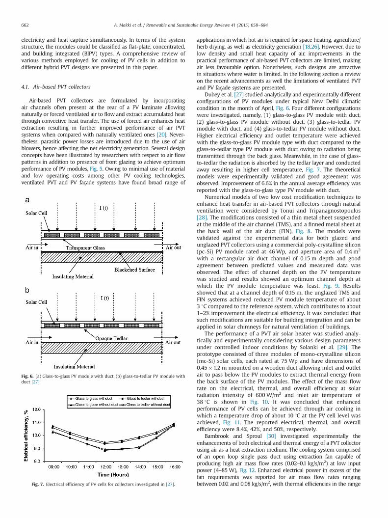
Dubey et al. [27] studied analytically and experimentally differentconfigurations of PV modules under typical New Delhi climaticcondition in the month of April, Fig. 6. Four different configurationswere investigated, namely, (1) glass-to-glass PV module with duct,(2) glass-to-glass PV module without duct, (3) glass-to-tedlar PVmodule with duct, and (4) glass-to-tedlar PV module without duct.Higher electrical efficiency and outlet temperature were achievedwith the glass-to-glass PV module type with duct compared to theglass-to-tedlar type PV module with duct owing to radiation beingtransmitted through the back glass. Meanwhile, in the case of glass-to-tedlar the radiation is absorbed by the tedlar layer and conductedaway resulting in higher cell temperature, Fig. 7. The theoreticalmodels were experimentally validated and good agreement wasobserved. Improvement of 6.6% in the annual average efficiency wasreported with the glass-to-glass type PV module with duct.
Numerical models of two low cost modification techniques toenhance heat transfer in air-based PVT collectors through naturalventilation were considered by Tonui and Tripanagnostopoulos[28]. The modifications consisted of a thin metal sheet suspendedat the middle of the air channel (TMS), and a finned metal sheet atthe back wall of the air duct (FIN), Fig. 8. The models werevalidated against the experimental data for both glazed andunglazed PVT collectors using a commercial poly-crystalline silicon(pc-Si) PV module rated at 46 Wp, and aperture area of 0.4 m2
with a rectangular air duct channel of 0.15 m depth and goodagreement between predicted values and measured data wasobserved. The effect of channel depth on the PV temperaturewas studied and results showed an optimum channel depth atwhich the PV module temperature was least, Fig. 9. Resultsshowed that at a channel depth of 0.15 m, the unglazed TMS andFIN systems achieved reduced PV module temperature of about3 1C compared to the reference system, which contributes to about1–2% improvement the electrical efficiency. It was concluded thatsuch modifications are suitable for building integration and can beapplied in solar chimneys for natural ventilation of buildings.
The performance of a PVT air solar heater was studied analy-tically and experimentally considering various design parametersunder controlled indoor conditions by Solanki et al. [29]. Theprototype consisted of three modules of mono-crystalline silicon(mc-Si) solar cells, each rated at 75 Wp and have dimensions of0.45�1.2 m mounted on a wooden duct allowing inlet and outletair to pass below the PV modules to extract thermal energy fromthe back surface of the PV modules. The effect of the mass flowrate on the electrical, thermal, and overall efficiency at solarradiation intensity of 600 W/m2 and inlet air temperature of38 1C is shown in Fig. 10. It was concluded that enhancedperformance of PV cells can be achieved through air cooling inwhich a temperature drop of about 10 1C at the PV cell level wasachieved, Fig. 11. The reported electrical, thermal, and overallefficiency were 8.4%, 42%, and 50%, respectively.
Bambrook and Sproul [30] investigated experimentally theenhancements of both electrical and thermal energy of a PVT collectorusing air as a heat extraction medium. The cooling system comprisedof an open loop single pass duct using extraction fan capable ofproducing high air mass flow rates (0.02–0.1 kg/s/m2) at low inputpower (4–85W), Fig. 12. Enhanced electrical power in excess of thefan requirements was reported for air mass flow rates rangingbetween 0.02 and 0.08 kg/s/m2, with thermal efficiencies in the range
Fig. 6. (a) Glass-to-glass PV module with duct, (b) glass-to-tedlar PV module withduct [27].
Fig. 7. Electrical efficiency of PV cells for collectors investigated in [27].
A. Makki et al. / Renewable and Sustainable Energy Reviews 41 (2015) 658–684662

of 28–55% and electrical PV efficiencies between 10.6 and 12.2% atmidday, Fig. 13. The system performance was also compared with theenergy requirement of the fan for a range of air mass flow rates. It isconcluded that, the low grade thermal energy output makes suchsystem suitable for residential applications, where the heat can beutilized for building heating.
Amori and Al-Najjar [31] investigated theoretically the perfor-mance of a hybrid PVT air collector for two different case studiesunder Iraqi climatic conditions. Improved thermo-electrical mathe-matical model of the PVT air collector considering the effect of
radiative heat transfer in the air duct, and the convective heat transfercoefficient from both the PV module back surface and inner surface ofinsulation to the working fluid were accounted for. The effective skytemperature correlation for relative humidity was also adopted in themodel [32]. Modified boundary conditions for better convergence andaccuracy of the electrical model were also considered. The modelpresented was validated against previously published experimentalresults and theoretical simulations of similar designs by Joshi et al. [33]and Sarhaddi et al. [34], and better alternative amongst the existingmodels was observed. The electrical and thermal efficiencies for thetwo cases considered were 12.3% and 19.4% for the winter day, whilethat for the summer day were 9% and 22.8% respectively. Although theoutput power in the summer was observed to be higher than that inthe winter (1.7 times at solar noon), the efficiency recorded in winterwas higher due to the negative temperature coefficient of efficiencyand higher fill factor.
Recently Amori and Abd-AlRaheem [35] have carried out aquantitative comparative study on different conceptual hybrid PVTcollectors for Iraq climate conditions. Four different types of air-based PVT collectors were adopted in experimental work, namely,Model I: PV modules without cooling, Model II: Hybrid PVTcollector with single duct double pass, Model III: Hybrid PVTcollector with double duct single pass, and Model IV: Hybrid PVTcollector with single duct single pass. A DC fan of power of (6 W)at the ducts’ outlet was used to pull air. A mathematical expressionof the PVT collector model IV was also developed based on energybalance to analyse the thermal and hydraulic performances of themodel. Model IV achieved better electrical performance comparedto model II and III, while the overall efficiency of model III washigher than that of model II and model IV due better heatextraction. Measurements also showed that optical losses were
Fig. 8. Air-based PVT collectors with thin metal sheet (TMS) and finned metal sheet (FIN) [28].
Fig. 9. PV surface temperature as function of air duct depth [28].
Fig. 10. Electrical efficiency variation with mass flow rate [29].
Fig. 11. Variation of electrical efficiency and cell temperature with and withoutflow in the duct [29].
A. Makki et al. / Renewable and Sustainable Energy Reviews 41 (2015) 658–684 663

introduced due to presence of glass cover in models II and III as theelectrical efficiency deviated before and after solar noon whencompared to model I, which agrees with the findings in Ref. [36].
Yun et al. [37] investigated a ventilated PV façade system consider-ing building characteristics and façade configuration for both pre-heating during winter and natural ventilation in summer, in additionto cooling of PV modules. The system incorporated transparentwindows, opaque PV panels with air gap and concrete compositewall, and air dampers, Fig. 14. The researchers introduced the effec-tiveness of a PV façade (PVEF) parameter to evaluate the buildingperformance in terms of heat transmission, ventilation, and daylight,in addition to the electrical efficiency of the PV modules. Results forthe hottest recorded day showed an approximate improvement of 15%of PV module efficiency through the ventilated system when com-pared with that without ventilation, Fig. 15.
Sukamongkol et al. [38] investigated the dynamic performanceof condenser heat recovery with air PVT collector for desiccantregeneration to reduce energy consumption of air conditioning for
a room in tropical climates. The system comprised of a livingspace, desiccant dehumidification and regeneration unit, air con-ditioning system, PVT collector, and air mixing unit. Warm dry airof 53 1C and 23% relative humidity was reported from themeasurements. In addition, energy saving in air condition of about18% was reported through such integration. However, electricalefficiency of only 6% of the daily total solar radiation was recorded.
Temperature prediction of a multi-junction solar cell based onpassive cooling was performed through theoretical thermal mod-elling by Min et al. [39]. A linear relationship between the heatsink area and the concentration ratio was observed in order tomaintain acceptable cell temperature. Recently, active air coolingof concentrator multi-junction solar cells by convection and sur-face radiation was studied theoretically by Al-Amri and Mallick[40]. In their study a triple-junction GaInP/GaAs/Ge solar cell witha Cu–Ag–Hg front contact was considered where air was forcedwithin ducts underneath aluminium base plate. Noticeable effectof surface radiation on the temperature of the PV cell wasobserved which agreed with the findings of a study conductedby Moshfegh and Sandberg [13]. Analysis also revealed thatincreasing the emissivity of the duct walls promoted the effect ofthe surface radiation. Simulation results under concentration ratioof 100� predicted a drop in solar cell temperature from 240 1C to150 1C as the emissivity was increased from 0 to 0.98. The effect ofthermal conductivities of solar cell holders and accessories inaddition to air inlet velocity, channel width, and thicknesses werealso examined and found to have great influence on the maximumcell temperature and critical concentration ratio.
Utilizing micro-channels, Agrawal and Tiwari [41] presented theconcept of series and parallel air flow arrangement of micro-channelsolar cell thermal tiles. The system comprised of air channels of depth500 mm made between a 0.0144m2 cell and tedlar allowing for thethermal resistance of tedlar to be eliminated, Fig. 16. Nine rows of fourseries-connected micro-channel solar cell thermal (MCSCT) tiles wereconnected in parallel to form a micro-channel PVT (MCPVT) module.Performance of the MCPVT in terms of overall energy, exergy andexergy efficiency was compared with that of single channel PVTmodule studied by Dubey et al. [27] with same (micro depth) flowrate. Results revealed that the MCPVT module achieved higher overallexergy efficiency, Fig. 17. Agrawal and Tiwari extended their study tovalidate their aforementioned MCPVT module, in addition to otherMCPVT module configurations being investigated [42].
Fig. 12. Air-based PVT with open loop single pass duct [30].
Fig. 13. Electrical and thermal efficiency variation of PVT with open loop singlepass duct [30].
A. Makki et al. / Renewable and Sustainable Energy Reviews 41 (2015) 658–684664

Theoretical analysis and optimization were carried out byRajoria et al. [43] adopting the designs proposed in Ref. [42],Fig. 18. Due to low value of bottom and side losses, case-II achievedthe highest value of overall thermal energy among other arrays.Nevertheless, higher grade of energy was achieved through theconfiguration in case-III with average electrical efficiency of 11.3%resulting in further 12.9% improvement in overall exergy efficiencythan that of case-II. Owing to increased number of PVT moduleconnected in series, case-III achieved the highest outlet airtemperature than other designs investigated.
In a recent study by Rajoria et al. [44] utilizing the sameconcept, the flow arrangement was modified such that air waspassed under two parallel-connected columns of 18 modules eachhaving 36 series-connected PVT tiles. Results were compared witharray in case-III in [43], and the new design was observed to bemore efficient. Further improvements in electrical efficiency, out-let air temperature, and annual overall exergy efficiency of 6.5%,18.1%, and 10.4% respectively were observed compared to that ofcase-III under the same climatic conditions. The study wasextended to investigate the Co2 mitigation and environmentalcost utilizing exergoeconomic analysis to reflect the financial gain/saving that can be obtained for four different cities in India. On a
similar study, carbon credit analysis for different air-based PVTarrays was conducted, enabling price comparison between sys-tems in respect to Co2 emissions for the city Srinagar (India) [45].
Three heat exchanger designs, namely, V-groove, honeycomband stainless steel wool incorporated at the rear of PV modulewere investigated experimentally [46], Fig. 19. Under irradiance of828 W/m2 and mass flow rate of 0.11 kg/s PVT module withhoneycomb heat exchanger achieved better performance withreported thermal and electrical efficiencies of 87% and 7.13%respectively. This was attributed due to larger surface area indirect contact with the PV module in addition to the uniform airflow resulting in enhanced heat transfer from the PV module toflowing air. Air PVT and ventilated PV façade systems have foundbroad range of applications offering a simple mechanism to coolPV cells and low grade thermal energy for space heating inresidential applications. Nevertheless, the low density and smallheat capacity of air limits the improvements in the performance ofair PVT collectors, hence making air less favourable option.
4.2. Liquid-based PVT collectors
At high operating temperature conditions, air cooling fails toaccommodate the temperature rise at the surface of PV cellscausing critical drop in their conversion efficiency. Liquid coolingoffers a better alternative to air cooling utilizing coolant as heatextraction medium to maintain desired operating temperature ofPV cells and a more efficient utilization of thermal energy captured[18,47–49]. Liquid-based PVT collectors are superior to air-basedones due to higher specific heat capacity of coolants employedleading to further improved overall performance [47,20]. In addi-tion, liquid-based PVT collectors offer less temperature fluctua-tions compared to air-based PVT making them more favourable[47]. The most common liquid-based PVT collector design com-prises of metallic sheet-and-tube absorber in which heat extrac-tion is attained via forced fluid circulation through series/parallel-connected pipes adhered to the rear of PV collector [18,51–53]. Asa result improved conversion efficiency is achieved and usefulthermal energy is made available for utilization in domestic andindustrial applications. Fluid circulation in such type of collectorsis accomplished utilizing either gravity-assisted circulation orcirculation pumps. Liquid-based PVT systems are commonly dis-tinguished according to working fluid employed [50]. Water is themost common fluid employed; however, refrigerants that are ableto undergo phase change at a relatively low temperature havebeen adopted in many systems recently. In this section a review onliquid-based PVT collector system utilizing water and other liquidrefrigerants as heat extraction fluids is presented.
4.2.1. Water-based PVT collectorsSeveral water-based PVT collector designs having different flow
patterns have been introduced and investigated both theoretically
Fig. 16. Micro-channel solar cell thermal (MCSCT) tile [41].
Fig. 14. Ventilated PV façade system (a) summer, (b) winter [37].
Fig. 15. PV efficiency and module temperature of ventilated PV façade [37].
A. Makki et al. / Renewable and Sustainable Energy Reviews 41 (2015) 658–684 665

and experimentally to achieve efficient cooling of PV cells, Fig. 20.However, the most common collector design studied consists of aPV module attached to an absorbing collector with serpentine of aseries or parallel tubes at the rear surface of PV modules (sheet-and-tube), Fig. 21. The PVT water collector operates such thatwater is forced to flow across tubes extracting the excessive heatfrom the PV cells, hence reducing the operating temperature of PVcells and transferring heat to be utilized for water and spaceheating applications. Researchers have identified several environ-mental and design parameters affecting the performance of suchtype of collectors including; mass flow rate, water inlet tempera-ture, number of covers, absorber to fluid thermal conductance, PVcells packing factor, collector length, duct depth absorber platedesign parameters [31,54].
An early theoretical study on combined PVT water system wasconducted by Garg and Agarwal [55]. The system comprised of aroof-mounted flat plate thermal collector with PV laminate pastedon top of an absorber plate, a storage tank, water pump for watercirculation through pipes, and a control system to control on/offswitching of the pump. Simulation was performed for differentoperating and design parameters including, PV cell areas, massflow rates and water masses. Zondag et al. [52] performed
numerical analysis on water-based PVT collectors having differentwater flow patterns that were discussed by de Vries in [53].Results in terms of electrical efficiency revealed that sheet-and-tube achieved conversion efficiency of 9.7%, higher than that ofPVT collectors with water channel, free flow, or two-absorber.However, the thermal efficiency predicted of the sheet-and-tubecollector was about 13–21% less than that of other designs. Huanget al. [56] compared the performance of an integrated PVT solarsystem with conventional solar water heater experimentally. Poly-crystalline PV cells were laminated on a thermal collector com-prising of a corrugated polycarbonate panel and thermal insula-tion layer attached at rear to form a PVT module. Thermalefficiency of 38% was reported (about 76% of conventional solarwater heater) electrical efficiency of 9%, and primary-energysaving efficiency of 60%, higher than either sole water heater orPV systems.
A PVT collector utilizing aluminium-alloy flat-box for domesticwater heating was constructed and experimentally investigated[57,58]. PV cells were adhered on the surface of the aluminiumalloy absorber which comprised of multiple extruded aluminiumalloy box-structure modules having their ends connected to twoaluminium traverse headers in which water circulation was
Fig. 18. Series and parallel arrangement of micro-channel solar cell thermal tiles with air cooling [42,43].
Fig. 17. Exergy efficiency utilising mirco-channel solar cell thermal (MCSCT) tile with air cooling [41].
A. Makki et al. / Renewable and Sustainable Energy Reviews 41 (2015) 658–684666

achieved through the themosyphon effect, Fig. 22. A thermalsimulation model of the hybrid system was developed and resultsagreed well with the measured data [57]. The validated model wasused to examine the steady state performance of the collectorunder different operating conditions of China. Under 800 W/m2 ofsolar irradiation, 20 1C ambient air temperature, 2.5 m/s windspeed, and water mass flow rate of 76 kg/(h m2) the ranges ofthe averaged daily thermal and electrical efficiencies were 37.6–48.6% and 10.3–12.3%, respectively [57]. Such variation in efficien-cies was observed to be dependent on the corresponding water-temperature and the level of solar radiation. Moreover, incorpora-tion of anti-freeze closed-loop design was suggested to overcomewater-freezing problems inside flow channels during severe cold
days in winter. He et al. [58] observed a slightly lower value of theoverall thermal-absorption of hybrid PVT system compared toconventional solar hot water collector attributed to lower opticalabsorption of the PV module as compared to the mat-blackthermal absorber surface. However, energy-saving efficiency of52% was achieved, which was above the conventional solar hot-water collector and slightly higher than the performance of theunglazed PVT system using plastic channel absorber under forcedcirculation tested by Huang et al. [56]. In a latter study by Chowet al. [59], computer simulation model of a vertical wall-mountedwater-based PVT was developed. The annual average thermal andcell conversion efficiencies of PVT collector with flat-box typethermal absorber and polycrystalline silicon cell were 37.5% and9.39%, respectively.
Ji et al. [60] presented a numerical model of wall-mountedwater-based PVT collectors for electricity and hot water supply, inaddition to improving the thermal insulation of the buildingenvelope. The work adopted the PVT collector design presentedearlier in [57,58]. Air gap was incorporated between the frontglazing and the PV surface to aid ventilation, which was addressedby Brinkworth et al. [61] to assist reduction in operating tempera-ture of PV modules. The BIPVT system comprised of six PVTcollectors each of aperture area 1.173 m2, a 420 l water storagetank, a water circulation pump and connecting pipes, Fig. 23. Theinfluence of packing factors, water flow rate, and water deliverypipe size, on the electrical and thermal efficiencies was analysed toenable optimal set of design parameters to be identified. Results
Fig. 20. Different configurations of water-based PVT collectors [48].
Fig. 21. Sheet-and-tube PVT collector [52].
Fig. 19. PV modules with different heat exchanger designs (a) honeycomb, (b) V-groove, (c) stainless steel wool [46].
A. Makki et al. / Renewable and Sustainable Energy Reviews 41 (2015) 658–684 667

revealed that as the pipe diameter increased from 0.01 to 0.02 m,the required pumping power reduced dramatically. Nevertheless,further increase in the pipe diameter results in increased thermalloss at the exterior pipe surface. The effect of water mass flow ratewas observed to improve the thermal efficiency and PV cooling asthe heat removal factor was enhanced. However, the advantage ofincreased flow rate diminishes when the critical flow rate isexceeded, thereby decreasing thermal efficiency.
The performance of water-based PVT collectors having differentconfigurations of absorber collectors was studied theoretically byIbrahim et al. [62], Fig. 24. The PVT collector comprised of poly-crystalline PV cells with hollow tubes attached underneath. Underwater flow rate of 0.01 kg/s spiral flow design proved to be the bestdesign with the highest thermal and cell efficiencies of 50.12% and11.98% respectively and output temperature of 31 1C. Different outputtemperatures were observed and attributed to the design configura-tion of the absorber, in which the closer spacing between tubesenabled more heat to be absorbed. In a further study, Ibrahim et al.
[63] investigated the water type PVT collector with spiral flow designexperimentally and compared it with single pass rectangular tunnelabsorber collector for air flow. Electrical and thermal efficiency of 64%and 11% respectively were achieved under samewater flow rate in theprevious theoretical study. Compared to the single pass rectangularcollector absorber with water flow, spiral flow design offers betterheat extraction and overall efficiency having low surface temperature.
Based on a theoretical model, Dubey and Tiwari [64] analysedthe thermal energy, exergy and electrical energy yields of water-based PVT collectors by varying the number of collectors in use,series/parallel connection patterns, and operating conditions. Thestudy concluded that the decision of PV cells covering factor woulddepend on the system requirements, in which partially covered byPV cells would be beneficial when hot water production is apriority. On the other hand, fully covered collectors enhancedelectrical energy yield leading to higher exergy efficiency. Dubeyand Tiwari extended their work to identify the economical/environmental benefits of their system through evaluation of theoptimum hot water withdrawal rate [65].
Brogren and Karlsson [66] used active water cooling method tocool a hybrid PVT system with stationary parabolic reflectors for lowconcentration ratio. The system consisted of a row of mono-crystalline silicon cells laminated on a copper fin thermal absorberwith a water tube welded on the back. Results of the experimentunder 3� concentration ratio measured a short-circuit current of5.6 A compared to identical module without concentration having ashort-circuit current of 3 A, hence showing a true optical concentra-tion of only 1.8� . Brogren and Karlsson justified the losses wereattributed to geometrical imperfections of the concentrating elementand optical losses in the reflector and the cover glazing. Meanwhile,significant amount of thermal energy 3–4 times the electric energywas produced at a water temperature of 50 1C.
Zhu et al. [67] conducted experimental work investigatingdielectric liquid immersion cooling for concentrator PV systemusing 250� dish concentrator. Mono-crystalline silicon PV cellswith back contacts were mounted on copper-clad electricallyinsulating substrates to form modules, each having 88 cellsconnected in series. Under 250 suns with direct normal irradiance
Fig. 22. Flat-box aluminium-alloy heat exchanger [57,58].
Fig. 23. Wall-mounted water-based PVT collectors [60].
A. Makki et al. / Renewable and Sustainable Energy Reviews 41 (2015) 658–684668

of 900 W/m2, cooling water inlet temperature of approximately31 1C and ambient temperature around 17 1C peak module tem-perature of 49 1C was observed. Moreover, temperature distribu-tion difference along the surface of less than 4 1C was attained.Due to eliminated contact thermal resistance of back cooling,liquid immersion facilitated improved cell performance to beachieved. In a more recent work, improvement in electricalefficiency of about 8.5–15.2% was reported through 1.5 mm thick-ness liquid layer over the cell surface by Han et al. [68].
Prudhvi and Sai [69] proposed improving the efficiency of thePV by active cooling to reduce the temperature losses considerablyand decrease reflection losses. A thin layer of water to flow on thesurface of the solar panel was investigated. The system considersclosed circuit flow, whereas “Ground Water Tunnelling” mechan-ism was applied to cool water absorbing the heat from the surfaceof the PV cells. Practical calculation based on the developed modelpresented a net 7.7% improvement in efficiency.
4.2.2. Refrigerant-based PVT collectorsRefrigerant fluids are normally used in systems combining PVT
collectors and solar-assisted heat pumps (SAHP), in which the PVT
collector serves as an evaporator where the refrigerant absorbsthermal energy available at the PV cells [70,71]. Low evaporationtemperature (0–20 1C) of refrigerant allows efficient cooling of PVcells to be achieved leading to significant increase in the perfor-mance [25,70,71].
The performance of PVT solar-assisted heat pump co-generationsystem was investigated theoretically and experimentally by Ji et al.[72]. The system comprised of nine (3�3) mono-crystalline PVTcollectors serving as direct-expansion evaporators for the heat pumpin which R22 refrigerant inside copper coil vaporizes at lowtemperature transferring absorbed heat to the condenser section,Fig. 25. Dynamic distributed model was developed to predict variousparameters including the pressure distribution of the PV evaporatorand along the copper coil attached, temperatures of PV cells and basepanel thermal collector, thermal and electrical efficiencies of thesystem, in addition to vapour quality and enthalpy. Validation of thesimulation results exhibited good agreement with measured dataexcept for the pressure drop of the PV evaporator which was foundmuch higher than the simulation prediction attributed to under-estimation of the saturated temperature gradient and higher tem-perature gradient along the copper coil observed during theexperiment. Under solar irradiation of 840W/m2 and ambient
Fig. 24. (a) Direct flow design, (b) serpentine flow design, (c) parallel–serpentine flow design, (d) modified serpentine–parallel flow design, (e) oscillatory flow design,(f) spiral flow design, (g) web flow design [62].
A. Makki et al. / Renewable and Sustainable Energy Reviews 41 (2015) 658–684 669

Fig. 26. PV/evaporator heat pump system [25].
Fig. 27. PV/loop-heat-pipe (PV/LHP) heat pump solar system [73].
Fig. 25. Schematic diagram of PV solar-assisted heat pump [72].
A. Makki et al. / Renewable and Sustainable Energy Reviews 41 (2015) 658–684670

temperature of 14 1C, the electrical and thermal efficiencies were 12%and 50% respectively implying enhanced cooling effect of the PV.
A novel PV/evaporator (PV/e) roof module for electricity gen-eration and acting as an evaporator of a heat pump system wasdesigned by Zhao et al. [25], Fig. 26. The performance wasevaluated theoretically with R134a refrigerant based on variousparameters including, top cover material, PV cells technology, andevaporation and condensation temperature of the heat pump. Anoptimized system configuration comprising of mono-crystallinePV cells, borosilicate top cover, evaporation and condensationtemperatures of 10 1C and 60 1C respectively was suggested. ThePV/e heat pump system was simulated under typical Nottingham(UK) weather conditions, and thermal and electrical efficiencies of60.93% and 9.21% respectively were reported.
Improved performance of PVT collector is attained throughutilising refrigerant cooling. Nevertheless, the practical feasibilityof such systems encounters several challenges including, unba-lanced refrigerant distribution, possible leakage of refrigerant, andmaintaining pressurization and depressurization at different partsof the system [18,73,74]. In attempt to override such challenges,Zhang et al. [73] presented a novel PV/loop-heat-pipe (PV/LHP)heat pump solar system, Fig. 27. The design utilized loop heat pipestructure with three-ways tube combining the PVT module and
the heat pump operations to overcome ‘dry-out’ problem encoun-tered in conventional heat pipe cooling. Theoretical evaluation andexperimental tests were conducted to define the performance ofthe system in terms of thermal and electrical efficiencies, and thesystem’s overall performance coefficient. Predicted simulationresults showed fair agreement with data measured. Parametricanalysis on the impact of several operational parameters includ-ing; solar radiation level, ambient temperature, air velocity,evaporation temperature of heat pump, top glazing cover, andheat pipe absorbing number was performed using the validatedmodel. Results under laboratory condition reported electrical,thermal, and overall efficacies of about 10%, 40%, and 50%,respectively. Overall coefficient performance of about 8.7 wasmeasured contributing to improvement of two to four times thanthat for conventional solar/air heat pump water heating systems.
In a similar concept, Xu et al. [75] adopted refrigerant cooling toabsorb heat from PV cells under low concentration using parabolicconcentrator reflecting the incident sunlight onto the surface ofPVT collector. Under climatic conditions of Nanjing (China) andlow concentration, the PVT integrated heat pump (LCPVT-HP)achieved an electrical efficiency of 17.5%, which was observed tobe 1.36 times higher than that of LCPV systemwithout cooling. Theeffective cooling of refrigerant can be seen clearly in Fig. 28, wherecomparison between base panel temperature of the LCPVT withand without the presence of cooling is presented.
Liquid cooling offers a better alternative to air cooling utiliz-ing coolant as heat extraction medium to maintain desiredoperating temperature of PV cells and a more efficient utilizationof thermal energy captured. In addition, liquid-based PVT col-lectors offer less temperature fluctuations compared to air-basedPVT making them more favourable in aiding a homogenoustemperature distribution on the surface of PV modules. Thelow evaporative temperature (0–20 1C) of refrigerants allowsefficient cooling of PV cells to be achieved leading to improvedperformance compared to water cooling. Nevertheless, thepractical feasibility of such systems encounters several chal-lenges as discussed earlier.
Fig. 28. PV cell operating temperature of low concentrating PVT integrated heatpump (LCPVT-HP) [75].
Fig. 29. Schematic diagram of heat pipe [18].
Fig. 30. Heat pipe cooling of PV cells [77].
Fig. 31. Cooling of low concentrator PV cell with heat pipe extruded fin [79].
A. Makki et al. / Renewable and Sustainable Energy Reviews 41 (2015) 658–684 671

4.3. Heat pipe-based PVT collectors
Heat pipes are considered efficient heat transfer devices thatcombine the principles of both thermal conductivity and phasetransition. A typical heat pipe consists of three sections namely,evaporator, adiabatic, and condenser sections, Fig. 29. Heat pipesprovide an ideal solution for heat removal and transmission, withone end serving as a thermal energy collector and the other end asa thermal energy dissipator [51]. Heat pipes have been consideredfor thermal management applications of PV technology due to theadvantages such technology provide over other cooling meanssuch as aiding uniform temperature distribution of PV cells,elimination of freezing that thermosyphon tube can suffer fromin higher latitudes, in addition to resistance to corrosion. However,the design of efficient heat pipe involves careful selection of asuitable combination of the heat pipe container material, workingfluid, and wick structure [76].
Russell [77] developed a cooling approach for concentrated PV(CPV) systems utilising heat pipes, to enable operation at elevatedtemperature and utilization of extracted heat for beneficial use.The systems comprised of a row of PV cells mounted on the outersurface of a heat pipe, where heat pipes are arranged next to eachother to form a panel, and Fresenl lenses were used to providehigh solar energy intensity, Fig. 30. The heat pipe used had internaltubes for circulating a fluid coolant through the heat pipe vapourfield to promote heat extraction. Details of the performanceparameters were not revealed in this study. Heat pipe approachfor CPV system under concentration ratio of about 24 suns waspresented by Feldman et al. [78]. The pipe was made out ofextruded aluminium surface and the evaporative working fluidwas benzene. Under ambient temperature of 40 1C and concen-trated solar radiation of 19.2 kW/m2, a minimum wind speed of1 m/s was required to keep the evaporator temperature below140 1C which limits the cooling capability of such system.
Akbarzadeh and Wadowski [79] utilized a passive coolingapproach using two heat exchangers piped together and filled
Fig. 32. Cooling PV concentrator through copper/water heat pipe with aluminiumfins [81].
Fig. 33. Micro heat pipe array cooling for conventional flat-plate PV module using(a) air, (b) water [83].
Fig. 34. Schematic drawing of a PV/PCM system [89].
Fig. 35. V-trough stand-alone PV/PCM system [121].
A. Makki et al. / Renewable and Sustainable Energy Reviews 41 (2015) 658–684672

with refrigerant to cool the back of the solar cells for a systemdesigned for concentration ratio of 20 suns, Fig. 31. The coolingmechanism proposed has a lower heat exchanger which is anevaporator and flooded with liquid refrigerant, and an uppersaturated vapour heat exchanger acting as a condenser. PV cellsin this system were attached to the evaporator and the uppercondenser was exposed to natural convective air cooling, inaddition to fins attached to the condenser to extend the externalheat transfer area. Results showed that the solar cell’s surfacetemperature did not exceed 46 1C. Improved performance of 50%was observed, generating 20.6 W compared to 10.6 W for the casewithout cooling arrangement.
Farahat [80] conducted experimental tests to evaluate thecooling capability of two approaches for concentrator PV cellsusing water and heat pipe cooling. The study investigated theinfluence of actual cell temperature on the performance of PV cellsby observing the electrical characteristics of PV cells when bothcooling techniques were employed. Results showed the influenceof temperature on the open circuit voltage which tended todecrease, while the short circuit current increased with theincrease in temperature. A comparison of the annual yield ofdifferent configurations revealed that decreased temperature of PVcells and a more reliable thermal performance were achievedwhen heat pipe cooling was applied.
Anderson et al. [81] investigated a design to cool PV concentratorunder concentration ratio of 500 suns utilizing a copper/water heatpipe with three wraps of mesh along with aluminium fins to enhancecell cooling with the aid of natural convection. Comparison betweendifferent working fluids compatible with copper heat pipes revealedthat copper/water heat pipes were able to carry more than six timesthe power of other working fluids. The heat pipe was fabricated andattached to an aluminium saddle in which the CPV cell sits on, Fig. 32.Optimum fin size and spacing for rejecting heat by natural convectionwere determined through series of CFD analysis. Heat rejection to theenvironment through natural convection achieved cell-to-ambientdifference of 43 1C when input heat flux of 40W/cm2 was applied,whereas temperature difference of 110 1C was measured whenaluminium plate was used for PV cells cooling. Adopting the same
Fig. 36. Surface temperatures at different levels of insolation and ambienttemperature of 20 1C [89].
Fig. 37. Surface Temperatures of PV/PCM systems with and without internal fins ata particular operating condition [89].
Fig. 38. Average measured surface temperature of finned PV/PCM systems [120].
Fig. 39. Schematic diagram of PV/PCM system with triangular cell [94].
A. Makki et al. / Renewable and Sustainable Energy Reviews 41 (2015) 658–684 673

concept design, Hughes et al. [82] performed CFD analysis to modelthe heat transfer from a conventional flat plate PV module. Aprototype of the system was fabricated and tested under weatherconditions of Dubai, UAE. With the aid of finned heat pipe arrange-ment and natural convection, the operating temperature of solar cellswas regulated at 30 1C under ambient temperature of 42 1C and windspeed of 4.2 m/s.
Tang et al. [83] utilized micro heat pipe arrays to investigate theperformance of conventional flat plate PV module using both air
and water as heat extraction mediums from the condenser sectionof the micro heat pipe array, Fig. 33. Experimental results of bothsystems were compared to an ordinary PV panel without cooling.Using water to cool the heat pipes contributed in achieving amaximum difference in electrical efficiency of 3% and averageincrease of 0.5%, while air cooling attained 2.6% and 0.4% respec-tively when compared to ordinary panel without cooling. In termsof output power, the water and air-cooled systems achievedaverage increase of 9% and 6.3% respectively.
The performance of a water thermpsyphon PVT and a heat pipePVT collector which was part of a solar assisted heat pump (SAHP-HP) was compared experimentally in Hefei, China in a studyconducted by Pei et al. [84]. Heat pipes were used to overcomethe freezing issues associated with water thermosyphon PVTcollectors in high latitudes and improve the conversion efficiencyof PV cells. Heat pipes filled with R600a were utilized and a heatexchanger was incorporated in a water tank (acting as a condensersection of heat pipe), where the working fluid condensed andreleased its latent heat into the water. The thermal efficiency of theheat pipe PVT collector recorded (23.8%) was 27.9% less than thatof the water thermosyphon (33%) attributed to large thermalinertial of the heat pipe PVT system. However, improvement of6.7% in the electrical efficiency with an average electrical efficiencyof 9.5% was achieved through utilizing heat pipe cooling due tosmall temperature difference between the PV cells compared tothat of the water thermosyphon which attained electrical effi-ciency of 8.9%. The study revealed that utilization of heat pipes inSAHP-HP system has great potential in reducing the powerconsumption of heat pumps as the heat pipe replaced part ofthe work of the heat pump.
More recently, Pei et al. [85] conducted dynamic modelling of aPVT collector utilizing heat pipe for heat extraction for PV modules.The collector comprised of 9 water-copper heat pipes joined togetherat the back of aluminium plate incorporated at the rear of a PVmodule. Low-iron tempered glass was used as a top cover glass of theinstallation preventing thermal losses and the entry of dust particles.Themodel was validatedwith experimental measurements performedunder the weather conditions of Hefei, China, and good agreementwas observed. Reported average electrical and thermal energy effi-ciencies were 10.2% and 45.7% respectively with average overall exergyefficiency of the 7.1%. Pei et al. [85] extended the research to provide acomprehensive parametric analysis based on the validated dynamicmodel to investigate the effect of water flow rates, PV cell coveringfactor, tube space of heat pipes, and different solar absorptive coatingsof the absorber plate. It was noted that both thermal and electricalefficiencies can be improved by decreasing the inlet water tempera-ture and increasing the mass flow rate. However, the packing factorhas an influence on the electrical efficiency greater than that of thethermal efficiency. Cost analysis was also presented in terms of theoverall performance improvements that could be achieved by increas-ing the PV cell covering factor and reducing the tube space of heatpipes. Results of the analysis revealed that heat pipe spacing of 0.09 mwas the most suitable and cost efficient option, further reduction intube spacing resulted in an increased number of heat pipes requiredfor producing a collector at an additional cost with only smallimprovement in the overall performance. In a similar design Wuet al. [86] investigated the influence of heat pipe cooling on main-taining a uniform cooling for PV cells by absorbing the excessive heataccumulating on solar cells isothermally. Results showed that the useof heat pipe cooling can assist uniform temperature of solar cells onthe absorber plate with variation of solar cell temperature less than2.5 1C. The overall thermal, electrical, and exergy efficiencies of theheat pipe PVT hybrid system reported were 63.65%, 8.45%, and 10.26%respectively.
Redpath et al. [87] investigated the performance of a linear axiscompound parabolic concentrating solar PVT (CPC-PVT) with heat
Fig. 40. Predicted surface temperature evolution using different combinations ofPCMs within PV/PCM system [94].
Fig. 41. Temperature regulation with the ratio of fins spacing on PV/PCM systemdesign [123].
Fig. 42. Temperature difference from reference PV using four different PCMs [118].
A. Makki et al. / Renewable and Sustainable Energy Reviews 41 (2015) 658–684674

pipe integrated for heat removal. The system was compared to asimple flat plate PVT (FP-PVT) with headers and risers. Reportedheat loss coefficient of the heat pipe-integrated PVT exhibitedlower value than flat plate. Under concentration ratio of 1.8� theCPC-PVT system attained additional 2.5% in the electrical conver-sion efficiency, while only 0.9% added efficiency was observedfrom the FP-PVT comparing both to a reference PV panel. A novelhybrid-structure flat plate heat pipe for a concentrator photovol-taic was fabricated and investigated by Huang et al. [88]. Thetemperature regulation mechanism comprised of a flat copperpipe with a sintered wick structure, and a coronary-stent-likerhombic copper mesh supports. Such modifications were able toeffectively reduce the thermal resistance of the heat pipe allowingfor further heat to be extracted. Experimental results with 40 Wconcentration on the cell achieved improvement of 3.1% in theelectrical conversion efficiency compared to an aluminium sub-strate in a single solar cell.
4.4. PCM-based PVT collectors
Phase changes Materials (PCMs) are substances that are able toabsorb and release large amount of energy as latent heat through areversible isothermal process at a particular phase transitiontemperature [89–92]. Latent heat storage using PCMs is superiorto sensible heat storage due to their higher energy storage densitywithin a smaller temperature range [50]. These materials areclassified as organics consisting of paraffin wax, and fatty acids,inorganics consisting of salt hydrates, and eutectic mixtures of
organic and inorganic PCMs [93–95]. A thorough review of thethree classified PCMs and their desirable characteristics, advan-tages, disadvantages, and behaviours during phase transition areavailable in literatures [96–98].
PCMs have been used widely as heat sinks for electronicdevices [32,99,100], and in passive thermal storage and manage-ment of buildings by adding encapsulated PCM particles duringmaterial production processing known as microencapsulatedPCMs (MEPCM) or by laminating PCM layers onto constructionpanels [101–106]. Incorporating PCMs in wallboards, roofs, andventilation heat exchangers can significantly reduce peak cooling/heating loads leading to reduced energy consumption, in additionto improving human comfort by reducing temperature swings[107–112]. As for electronic devices, incorporating PCMs intotraditional heat sinks for electronic chips within mobile phonesand computers have been proven effective for thermal regulators[113–115].
As far as PV systems are concerned, conventional passivecooling techniques are unable to provide the required coolingduring peak solar radiation periods leading to a deterioratedperformance of PVs. Furthermore, inhomogeneous temperatureprofiles which affect the generation capacity of PV systems standas a limitation in other passive cooling methods [116,117].Recently, few studies were conducted to investigate the incorpora-tion of PCMs in PV systems to tackle the aforementioned issues.
Various PCM-based PV concept designs have been reported inliteratures. The most common system studied considers incor-poration of PCMs in Building Integrated Photovoltaic (BIPV), Fig. 34[89,118–120]. Stand-alone PV collectors with PCM thermal storagehave also been reported in few literatures, Fig. 35 [121,122]. Thesedesigns have the same basic components in common from whichthe system is constructed. However, diversity in the heat transfermechanisms from the PV module was noted. The unutilized part ofsolar radiation striking the surface of PCM-based PV systems isconducted as heat to the PCM through the PCM container materialcausing increased temperature of PCM. At a certain phase transi-tion temperature the PCM starts melting and due to continuoustemperature rise the melt extends into the PCM. During latent heattransfer process the PCM effectively acts as a heat sink maintaininga regulated temperature of the PV modules close enough to itsmelting/freezing point. Once the melting process is complete, anyfurther heat stored will manifest as a temperature rise. Suchprocess is reversible wherein solidification cycle takes place asthe temperature drops below the melting point.
Fig. 43. Output power data of different system configuration taken from [121].
Fig. 44. Operation modes of thermoelectric TE module [131].
A. Makki et al. / Renewable and Sustainable Energy Reviews 41 (2015) 658–684 675

Non-linear motion of solid–liquid interface, presence of buoy-ancy driven flows in the melt, and volume expansion of the PCMduring melting/solidification introduce complexities in the analy-tical investigation of PCM-based applications [89]. Therefore,numerical and experimental investigations represent majority ofthe work reported in this field. Huang et al. [89] developed a two-dimensional model to investigate the use of solid–liquid PCM toregulate the temperature of BIPV near its characterizing tempera-ture of 25 1C. The model was validated with experimental mea-surements and good agreement was achieved. Parametric analysisbased on the validated model was conducted to predict thethermal control of a range of PV/PCM configurations and operatingconditions in order to optimize the PV/PCM design. Insolationlevel had a great influence on the thermal regulation of the PCM in
which the time required for PCM to completely melt was reducedas solar intensity increased, Fig. 36. Improvements in the thermalmanagement of the PCM were achieved through incorporatingmetal fins extending in the PCM as observed in Fig. 37.
Thermal performance of different internal fin arrangements toenhance the thermal conductivity of bulk PCM was investigatedexperimentally using RT25 and GR40 paraffin waxes by Huang et al.[120]. Of the different fin arrangements investigated straight fins ofwidth 36mm led to the lowest surface temperature. Soft-iron wirematrix however, sustained stable temperature during phase transitionunder 750W/m2 and ambient temperature of 2371 1C as shown inFig. 38. Reported thermal control of solid–liquid RT25 PCM wassuperior to granular GR40 PCM as a thermal regulation of below32 1C for a period of 150 minwas achieved. Increasing the width of thefin resulted in a longer duration at which the temperature wasregulated, while decreasing the spacing between fins further reducedthe temperature at the surface of the PVmodules at the expense of thetemperature control duration. The study concluded that the tempera-ture was mainly influenced by the number, dimension, form of fins,and type of PCM material used.
With regards to the declined thermal regulation period notedthrough the use of internal fin arrangements, a modified PV/PCMsystem integrated with two PCMs with different phase transienttemperatures was investigated [94]. Various cases using differentcombinations of PCMs with different melting temperatures intriangular shaped cells were considered, Fig. 39. Compared withthe previously studied straight fins PV/PCM, Huang reported that thesystem with triangular cells was able to dissipate the stress resultingfrom volume expansion and extended the thermal regulation period.Results of the research revealed that the thermal regulation perfor-mance of the PV/PCM depended on the thermal mass of PCM,position of PCMs inside the PV/PCM system, and thermal character-istics of both PCM and PV/PCM system structure. Furthermore, forthe combination of PCMs the lower phase transient PCM dominatedthe whole system performance. Under insolation level of 1000W/m2
and ambient temperature of 20 1C the systemwith PCMs RT27–RT21had the lowest temperature rise due to its lower melting tempera-ture, while RT27–RT27 was able to regulate the temperature for alonger period, Fig. 40.
The effect of crystalline segregation and convection in meltedPCM was also investigated by Huang et al. [123]. The physicalstructure of bulk PCM in PV/PCM systemwith phase transition wasexamined. Increased porosity in the centre of the bulk PCM due tothe effect of volume contraction when the PCM solidified wasobserved, resulting in an increased heat transfer resistance.Although horizontal metal fins enhanced the heat transfer process,obstruction of the movement of bubbles formed under the finsduring PCM melting was observed leading to increased heattransfer resistance. Thermal stratification was as well examined
Fig. 45. Cooling of PV cell through TE cooler [142].
Fig. 46. Incorporation of TE generators with PV cell (a) non-concentrated(b) concentrated [136].
Fig. 47. A scheme of hybrid PV/T system with TEGs: (1) solar cell, (2) cell’s backelectrode, (3) TEG, (4) heat extractor, (5) plane collector, (6) thermal tank [139].
A. Makki et al. / Renewable and Sustainable Energy Reviews 41 (2015) 658–684676

through temperature measurements within the PCM, and resultsshowed that with certain fin interval (12–24 mm) the thermalstratification could be reduced and convection had improvedeffect on heat transfer rate leading to more uniform temperaturedistribution in the PV/PCM system and improved thermal regula-tion period. A correlation between the ratio of fins spacing tosystem depth that can be used to characterize the period oftemperature control and temperature regulation capacity is shownin Fig. 41.
Hassan et al. [118] conducted experimental tests and observedthe effect of the thermal conductivity of the container materialwherein the PCM resides and the effect of thermal mass of PCM onthe PV thermal regulation at different insolation levels. Aluminiumand Perspex were used as containers attached to the rear of PVmodule to absorb excessive heat, and various PCMs with differentconductivities were examined. Results revealed that salt hydrateCaCl2 PCM in aluminium container achieved the best thermalregulation performance at insolation level of 1000 W/m2 andambient temperature of 2071 1C as shown in Fig. 42. It wasevident that the thermal regulation performance of PCMsdepended on both the thermal mass of the PCM and the thermalconductivities of both PCM and the overall PV/PCM assembly.
Thermal regulation of an enhanced solar insolation stand-alonePV/PCM system using V-trough was conducted by Maiti et al.[121], Fig. 35. Temperature regulation of 65 1C under 1.7� averageenhancement of solar insolation was attained. The investigatedsystem achieved 55% improvement in the overall power genera-tion through incorporating a bed of metal-embedded paraffin waxas PCM at the rear of the PV module, even under low windvelocities and moderately high insolation and ambient tempera-ture conditions, Fig. 43.
Ho et al. [124] conducted a numerical investigation on MEPCMincorporated in a building structure to realize the thermal andelectrical performances of BIPV module under various operatingparameters. The significance of PCM melting point choice to matchthe operating conditions was addressed and proved to be influen-tial on the PCM phase transition cycle completion. In a morerecent study, the effectiveness of using a layer of water-saturatedMEPCM as a passive thermal management medium for BIPV wasexplored by Ho et al. [119]. Improvement in average electricalefficiency of 2.006% over the corresponding efficiency for areference PV module was achieved through integrating a layerMEPCM with a melting point of 30 1C and thickness of 30 mm.PCM with water circulation integrated at the rear of the PV modulewas examined by Bouzoukas [50]. Among other approaches to coolPV systems PCMs presented fair performance improvementsleading to enhanced electrical efficiency and low heat loss coeffi-cient as compared to that of air-, water-, and heat pipe-basedsystems investigated.
4.5. Thermoelectric (PV-TE) hybrid systems
Thermoelectric (TE) modules are solid-state semiconductor devicesthat are able to convert thermal energy directly into electrical energyor vice versa. A TE module comprise of thermoelectric elements madeof two dissimilar semiconductors, p- and n-type junctions connectedelectrically in series and thermally in parallel [125]. TE modulespossess salient features of being compact, lightweight, noiseless inoperation, highly reliable, maintenance free and no moving or com-plex parts [125–129]. Such devices are categorized into two types ofconverters depending on the energy conversion process; Thermo-electric Generators (TEGs), generating electricity from a temperaturegradient, and Thermoelectric Coolers (TECs), converting a directcurrent into a temperature gradient [126,130], Fig. 44.
Thermoelectric generators have great potential in waste heatrecovery from power plants, automobile vehicles, and solar energyapplications where direct heat-to-electricity conversion can occurusing a phenomenon called the Seebeck effect [132–135]. For thepast 10 years several studies have been conducted to investigatethe feasibility of incorporating TEGs with PV technology in acombined cell-scale, flat plate, or even concentrator type systemsto harvest energy through thermal waste utilization [136–141]. Onthe other hand, thermoelectric coolers have been widely used inelectronic devices and medical instruments as they are capable ofproviding refrigeration and temperature control for such devicesallowing them to operate at a certain temperature level utilizingthe Peltier effect [129,142–144]. In this section a review on themost recent advancements of incorporating of TE modules withPVs to aid lower temperature regulation using TE coolers (TECs) orenergy harvesting through direct thermal-to-electricity conver-sion through TE generators (TEGs) are presented.
TE coolers operate in suchway that supplying a low DC voltage to aTEC module enables heat to transfer from one side to the other.Incorporation of TE coolers with PV modules have been studiedextensively for refrigeration and temperature management systems,however; these systems are out of the scope of this work. Acomprehensive review on PV-driven TEC systems is available in Ref.[144]. Meanwhile, limited research has been done in the application ofTE coolers to regulate the temperature of PV cells. The most commondesign of TE cooler for PV (PV-TEC) systems comprise of TEC moduleinstalled at the rear PV cell with aluminium sheet in between so as tospread the heat dissipated at the back surface of the PV cell, Fig. 45[129,142,143]. In such system, a fraction of the generated power by thePV cell is fed to the TEC module to provide the necessary cooling effectfor the PV cell. The cooling effect of a TEC module is characterized bythe amount of power supplied, meaning themore electricity is fed intothe TEC module the greater the cooling effect for the PV cell. However,there is a trade-off between the net generated power by the systemand the power consumed by the TEC module, in which substantial
Fig. 48. Scheme of hybrid system with TEG and concentrated solar radiation: (1) concentrating lens, (2) tracking system, (3) TEG, (4) heat extractor, (5) PV panel, (6) solarradiation [139].
A. Makki et al. / Renewable and Sustainable Energy Reviews 41 (2015) 658–684 677

amount of power is required to achieve significant amount of coolingwhich can exceed the generated power by PV cells. Therefore, severalapproaches and control algorithms can be applied by controlling thetemperature of the PV cell and keeping it under a specific limit underdifferent conditions or optimization to find the optimal value of thesupplied electrical current for the TEC module which leads to themaximum net generated power [142].
Najafi and Woodbury [142] investigated cooling of PV cell utilisingthe Peltier effect of TEC modules through theoretical model. Thesystem considered a TEC module attached to the back side of a single
PV cell, Fig. 45. The model was used to estimate the temperatureswithin the system, the required power to supply the thermoelectriccooling module, and the additional power produced by PV cell due tothe cooling effect. Evaluation of power saving due to temperaturereduction in the PV cell minus the utilized power by the TEC modulewas estimated through genetic algorithm based optimization in whichan optimum value of the supplied electrical current for the TECmodule was estimated, which leads to the maximum net generatedpower at a specific operating conditions. Results revealed that addi-tional power due to cooling was generated, nevertheless, for theoptimal current the cooling effect was insignificant and the tempera-ture reduction did not exceed 8 1C. Moreover, it was noted that theperformance of the system strongly depended on the figure of merit ofthe TE module.
Kane et al. [129] utilized TE coolers to aid cooling of PV modules ina building integrated system. A dynamic model of the BIPV/TE systemwith consideration to PV panel temperature was developed to assessthe performances improvement of the TE coolers on PV. The BIPV/TEsystem comprised of TE module attached at the back of PV modulewith heat sink attached to the other side of the module to increaseheat transfer process. Results revealed that BIPV/TE combined systemcan be operated at 53 1C PV module temperature without loss of PVpower thus module can be cooled down by 10 1C which will enhancelife of PV module, and therefore its performance.
Thermoelectric coolers for improved performance of buildingintegrated photovoltaic (BIPV) modules were investigated experi-mentally by Choi et al. [143]. As control of thermoelectric elementscan be regulated independently in an outdoor environment usinga micro-controller, the operating temperature of PV cells can bemaintained near the characterizing temperature of 25 1C. A controlalgorithm was built to control the DC current fed into the TEmodule to achieve the required cooling effect. Comparisonbetween BIPV modules using a ventilator and thermoelectricelements was presented. The TEC was operated when the tem-perature of the BIPV module exceeds a set temperature, henceoperating the BIPV module within the control value only duringdays with high radiation to achieve additional net power genera-tion. Experimental results showed that average module tempera-ture of 24.48 1C was observed for the BIPV system using athermoelectric element, while that with ventilator attained aver-age module temperature of 33.31 1C. The output power of the BIPVsystem was observed to be higher than that with the conventionalmethod and the efficiency of BIPV system was increased.
Table 2Efficiency of TEG-based concentrator systems for maximum irradiance [139].
System Concentrator-TEG PVM-concentrator-TEG
PV – – a-Si a-SiΔT (K) 150 250 150 250Concentration ratio 55 95 122 211η0.7 (%) 4 6 – –
ŋ2.4 (%) 12.4 15.3 15.6 17
Fig. 49. Calculated temperature dependence efficiency as function the temperaturedifference: (1) PV cells, TEG with different ZT¼2.4 curve (2), 0.7 curve (3), and4 curve (4), total efficiency with different TEGs (ZT¼4 curve (5), 0.7 curve (6), and2.4 curve (7) [139].
Fig. 50. Generated PVTE power as a function of irradiance for four values of thefigure of merit Z, and generated PV power as a function of irradiance at STC andmodule temperature [145].
Fig. 51. Schematic of PE-TE hybrid module [146].
Table 3Performances of TEG, solar cell and hybrid PV-TE module [146].
FF Voc (V) Isc (A) Pmax (W)
Max Stable Max Stable Max Stable
TEG 0.242 3.25 0.86 0.26 0.07 0.204 0.146Solar cell 0.43 2 0.22 0.189Hybrid module – – – 0.393 0.204
A. Makki et al. / Renewable and Sustainable Energy Reviews 41 (2015) 658–684678

On the other hand, the incorporation of TE generators with PV cellshas been studied extensively to harvest the solar energy available forthe sun. In an investigation on the possibility of using TEGs in solarhybrid system done by Vorobiev et al. [136], two different designswere theoretically studied, Fig. 46. To increase the electricity produc-tion in PVT the author suggested directing the heat flux originatingbetween the PV module and heat extractor through thermoelectricgenerator. In the first model the PV cells operated at low temperature,and the thermal solar radiation was concentrated onto the hot side ofthe high temperature stage (HTS). Therefore, high temperature can beconverted to electrical energy through the use of TEGs as the HTS. Onthe other hand, the second design considered was a system withoutsolar spectrum division, inwhich PV cells operate at high temperature.The investigation considered two types of PV cell technologies; GaAssingle junction cell for model A, andmulti-junction GaAs-based cell formodel B with corresponding room temperature efficiencies of 24% and30% respectively under concentration ratio of 50� . Predicted resultsshowed that model Awas able to enhance overall system efficiency by5–10% while model B with PV cells operating at high temperature didnot exhibit much influence on improving the overall conversionefficiency. The investigation however, relayed on theoretical calcula-tion for the investigated models without experimental justificationsbesides, predictions were given for TEG modules with high figure ofmerit assumed that are not available in current stage of TEGtechnology.
Adopting similar design as in [136], an experimental investiga-tion was performed to asses the integration of TEGs in a solarhybrid system in [139]. The model utilized the heat generatedunder one sun in each PV cell and passed it through individual TEGthat have good thermal contact with this cell from one side, andwith heat extractor from the other side. The general scheme of thesystem is shown in Fig. 47, where direct non-concentrated sun-light falls onto the PV panel where each cells possesses a back
electrode with high thermal conductivity. The electrodes havedirect thermal contact with the hot plate of corresponding TEG. Itwas noted from the efficiency estimations that with traditionalTEGs, one cannot expect significant improvement in electricalefficiency. Due to heat flux losses on the way to TEG, the expectedincrease of electrical efficiency provided with this TEG model(ZT=0.7) was around 1%. Taking the value of ZT equal to 2.4 largerincrease due to TEG of 3.2% will be obtained; with ZT=4, theefficiency will be 4.1%. Thus the use of existing traditional TEGs inthe system studied cannot be really effective, but the advancedTEG might be useful. The authors extended their research toinvestigate the potentials of achieving better conversion efficiencythrough concentrated radiation based on three different geome-tries shown in Fig. 48. From the results obtained it was observedthat the conversion efficiency of TEG in concentrated sunlightcomparable to that of commercial PV panels can be achieved aspresented in Table 2. Although the cost of TEGs currently is slightlyhigher than that of PV modules of equal surface area, criticalreduction can be attained taking into account area reduction ofTEG at concentrated irradiation. The second system utilizingconcentrated illumination is represented by Fig. 48(b) in whichboth PV module and TEG work in concentrated irradiation and atelevated temperature, the efficiency of PV decreases with anincrease of temperature whereas the TEG’s efficiency increases.Therefore, an optimal temperature corresponding to the max-imum value of electrical efficiency of the whole device anddepending upon the parameters of its components can be identi-fied, Fig. 49. In relation to the hybrid system shown in Fig. 48(c) atransparent a-Si based PV modules with efficiency of 10% and lowtemperature coefficient compared to c-Si PV modules were used,such modules have the advantage of withstanding high tempera-ture due to the high concentration ratios. The thermal part of thesolar spectrum that passes through the cell was determined by the
Table 4Advantages and disadvantages of different thermal management techniques [118].
Natural aircirculation
Forced air circulation Liquid cooling Heat pipes Thermoelectriccooling
PCM
Advantages � Passive heatexchange
� Low initial cost� No
maintenance� Easily
integration� Longer life� No Noise� No electricity
consumption
� Higher heat transferrates compared tonaturalcirculation of air
� Independent ofwind directionand speed
� Higher mass flowrates than naturalair circulationachieving high heattransfer rates
� Higher temperaturereduction comparedto natural air
� Higher heat transferrate compared tonatural and forcedcirculation of air
� Higher mass flowrates compared tonatural and forcedcirculation of air
� Higher thermalconductivity andheat capacity ofwater compared toair
� Higher temperaturereduction
� Passive heatexchanger
� Efficient heattransfer
� Simple� Easy to
integrate
� No moving parts� Noise Free� Small size� Easy to integrate� Low
maintenance costs� Solid state heat
transfer
� Higher heat transferrates compared to bothforced air circulationand forced watercirculation
� Higher heat absorptiondue to latent heating
� Isothermal natural ofheat removal
� No electricityconsumption
� Passive heat exchange� No maintenance cost
Disadvantages � Low heattransfer rates
� Accumulationof dust in inletgrating furtherreducing heattransfer
� Dependent onwind directionand speed
� Low thermalconductivityand heatcapacity of air
� High initial cost forfans, ducts to handlelarge massflow rates
� High electricalconsumption
� Maintenance cost� Noisy system� Difficult to integrate
compared to naturalaircirculation system
� Higher initial costdue to pumps
� Higher maintenancecost compared toforced air circulation
� Higher electricityconsumptioncompared to forcedair circulation
� Leakage andpressurization issues
� Expensive� Dust
accumulationon the inletgranting
� Dependent ofwind speedand direction
� Dry out� Hot spots� Leakage
� Heat transferdepends onambientconditions
� No heat storagecapacity
� Require electricity� Requires efficient
heat removal fromwarmer side foreffective cooling
� Costly for PVcooling
� High PCM cost� Some PCMs are toxic� Some PCMs have fire
safety issues� Some PCMs are
strongly corrosive� PCMs may have
disposal problem aftertheir life cycle iscomplete
A. Makki et al. / Renewable and Sustainable Energy Reviews 41 (2015) 658–684 679

Table 5Summary of some of the various systems reviewed.
Work Configuration PVtype
Electricalefficiency
Thermalefficiency
Overall exergyefficiency
PV celltemperature
Air-based Dubey et al. [27](Sim.)
Glass-to-glass PV module with forced air N/A 10.41% (Annualaverage)
N/A N/A 55–75 1C
Tonui andTripanagnostopoulos[28] (Sim.)
Unglazed PVT with metal sheet at the middle of theair channel (Natural Convection)
Polyc-SiPV
1–2%Improvement
13% N/A 3 1C (Reductioncompared toregular Air-PVT)
Glazed PVT with metal sheet at the middle of the airchannel (Natural Convection)
Polyc-SiPV
4%Improvement
12% N/A 4 1C (Reductioncompared toregular Air-PVT)
Unglazed PVT with finned metal sheet at air duct(Natural Convection)
Polyc-SiPV
1–2%improvement
18% N/A 3 1C (Reductioncompared toregular Air-PVT)
Glazed PVT with finned metal sheet at air duct(Natural Convection)
Polyc-SiPV
10%Improvement
40% N/A 10 1C (Reductioncompared toregular Air-PVT)
Solanki et al. [29](Exp.)
PVT air solar heater Monoc-SiPV
8.40% 42% N/A 10 1C drop
Bambrook and Sproul[30] (Exp.)
PVT with open loop single pass duct and extractionfan
Monoc-SiPV
10.6–12.2% 28–55% N/A 22–28 1C
Amori, and Al-Najjar[31] (Sim.)
PVT with single pass air duct Monoc-SiPV
12.3% (Winter),9% (Summer)
19.4% (Winter),22.8%(Summer)
N/A N/A
Min et al. [39]. (Exp.) Concentrator PV with metal plates heat sink (400� ) MJ-SiPV
N/A N/A N/A 37 1C
Al-Amri and Mallick[40] (Sim.)
Triple-junction solar cell with forced air cooling(100� )
MJ-SiPV
N/A N/A N/A 150 1C
Rajoria et al. [43](Sim.)
Micro-channel PVT tiles, two integrated columnseach having 18 PV modules in series are connectedin parallel (Case III)
Monoc-SiPV
11.30% N/A N/A N/A
Rajoria et al. [44](Sim.)
Micro-channel PVT tiles, two parallel-connectedcolumns of 18 modules each having 36 series-connected PVT tiles to Case III in [41]
Monoc-SiPV
6.5%(Improvement)
18.1%(Improvement)
10.4%(Improvement)
Othman et al. [46](Exp.)
Air-based PVT module with honeycomb heatexchanger
Monoc-SiPV
7.13% 87% 4 1C drop
Water-based
Chow et al. [57](Exp.)
PVT collector with aluminium-alloy flat-box Polyc-SiPV
10.3–12.3% 37.6–48.6% N/A N/A
Chow et al. [59](Sim.)
Vertical wall-mounted water-based PVT Polyc-SiPV
9.39% 37.50% N/A N/A
Ibrahim et al. [62](Exp.)
PVT collector with spiral flow design Polyc-SiPV
11% 64% N/A N/A
Zhu et al. [67] (Exp.) Dielectric liquid immersion cooling for CPV (250� ) Monoc-SiPV
N/A N/A N/A 49 1C
Refrigerant-based
Ji et al. [72] (Exp.) PVT solar-assisted heat pump co-generation withR22 refrigerant
Monoc-SiPV
12% 50% N/A N/A
Zhao et al. [25] (Sim.) PV/evaporator roof module of heat pump systemwith R134a refrigerant
Monoc-SiPV
9.21% 60.93% N/A N/A
Zhang et al. [73](Sim.)
PV/loop-heat-pipe (PV/LHP) heat pump solar system N/A 10% 40% N/A N/A
Xu et al. [75] Low concentrating PVT with heat pump (LCPVT-HP)using R134a refrigerant
N/A 17.570.4% N/A N/A 51 1C
Heat pipe-based
Akbarzadeh andWadowski [79] (Exp.)
Heat pipe cooling for CPV (20� ) N/A N/A N/A N/A 46 1C
Anderson et al. [81](Sim)
Heat pipe with aluminium fins cooling for CPV(500� )
N/A N/A N/A N/A 43 1C aboveambient
Hughes et al. [82](Sim.)
Finned heat pipe and natural convection forconventional flat plate PV
N/A N/A N/A N/A 30 1C
Pei et al. [84] (Exp.) Heat pipe PVT collector with R600a (part of a solarassisted heat pump)
N/A 9.50% 23.80% N/A N/A
Pei et al. [85] (Sim.) Heat pipe cooling for flat plate PV N/A 10.20% 45.70% 7.10% N/AWu et al. [86] (Sim.) Heat pipe cooling for flat plate PV N/A 8.45% 63.65% 10.26% N/ARedpath et al. [87] Compound parabolic concentrating solar PVT (CPC-
PVT) with heat pipeN/A 2.5% (Addition) N/A N/A N/A
Huang et al. [88] flat plate heat pipe for CPV N/A 3.1%(Improvement)
N/A N/A N/A
PCM-based Huang et al. [89](Sim.)
Flat plate PV with PCM N/A N/A N/A N/A 37.5 1C
A. Makki et al. / Renewable and Sustainable Energy Reviews 41 (2015) 658–684680

value of band gap, in which for a-Si was 1.6 eV (45% taking intoaccount reflection losses). As per Table 2 the system design (c) canbe quite efficient with PV cells made of semiconductor with higherband gap such as CdSe, and using TEG with advanced materials.
Van Sark [145] conducted theoretical investigation on the feasi-bility and performance enhancements utilizing thermoelectric con-verters for electricity generation in a PV integrated system. A hybridmodule was formed by attaching a series of low temperature thermo-electric converters (i.e. ZTZ1 at 300 K) to the back side of a PVmodule to utilize thermal waste available from the PV module. Tomaintain temperature difference of about 50–60 1C across the TEconvertor plates, the converters were mounted on a heat sink to keepthe cold plate cooled convectively. The developed model takes intoaccount the influences of irradiance, temperature, and figure of meriton the performance of the PV-TE hybrid module. Results revealed thatfor the current near-maximum value of Z¼0.008 K�1 additionalefficiency of 1.53% was estimated by incorporating thermoelectricconverters, while for the current maximum value of Z¼0.004 K�1,PV-TE efficiency of 14.03% was estimated, which resembles thegenerated power when the PV module was operating at a constanttemperature of 25 1C (STC), Fig. 50. The annual performance of thedeveloped system for two cities, namely; Malaga, Spain, and Utrecht,the Netherlands was also evaluated using set of hourly averageirradiances and daily ambient temperature and an increase by 14.7%and 11%, for Malaga and Utrecht, respectively was found through theintegration of TE converters. Nevertheless, the model ignored theinfluence of radiation loss through top cover and assumed that thetemperature at the hot side of the TE converter equaled the ambienttemperature, which may not be realized in practice.
More recently, experimental and theoretical investigation on solarhybrid generation system consisting of 170 mm�40mm silicon thinfilm solar cell, thermoelectric generators, and heat collector wasconducted by Deng et al. [146]. The hybrid system developed was inprinciple similar to the PV-TE hybrid module discussed earlier by VanSark [145], however, an optimized heat collector design with threelayers namely; absorbing, conducting, and insulation layers wasintroduced to obtain larger temperature difference across the TEG,Fig. 51. The absorbing layer was used to enhance the absorption of sunlight, and for that purpose three different types of heat absorbing layerwere tested, namely; Graphite, optical–thermal thin film, and blackpolymer tape. A bowl-shaped copper foil was fabricated and fixed tothe side and back of the solar cell to accelerate heat conduction to the
TEG, while a layer of foam was applied to prevent heat loss. Toenhance heat dissipation and maintain larger temperature differenceacross the TEG plates, both aluminium fin heat sinks attached at thecold side of converter and water cooling was investigated. To assessthe performance of the TEG in the hybrid system the open circuitvoltages and short circuit currents for the design with black polymertape as an absorbing layer and aluminium fins to cool the TEG wererecorded in Table 3. Results showed that the integrated design had anenhanced overall performance. The numerical simulation performedon TEG estimated increased heat flux on the hot side of the converterby more than tenfold using the optimized thermal collector design.
5. Discussion
Various methods can be employed to achieve cooling action forPV systems. However, the optimum cooling solution is criticallydependent on several factors such as, system arrangement, PVtechnology employed, types of concentrators’ geometries, andweather condition at which the system is installed. Hybrid PVSystem offer a practical solution to increase the electrical powerproduction from PV panels and reduce the heating loads, inaddition to the recovery of heat extracted from the panels. Heatextraction from PV modules utilizing various mechanisms waspresented. Various designs employing air, liquid, heat pipe, PCM,and thermoelectric modules to aid cooling of PV cells werediscussed along with the parameters influencing the systemperformance.
Air cooling of PV system provides a simple technique tothermally regulate the temperature of PV cells owing to minimaluse of material and low operating cost among other PV coolingtechnologies. Forced air enhances heat extraction resulting infurther improved performance of air PVT systems when comparedwith naturally ventilated ones at the expense of some parasiticpower losses introduced due to the use of air blowers. Never-theless, the low density and small heat capacity of air, limits theimprovements in the performance of air PVT collectors making airless favourable option. On the other hand, liquid cooling offers abetter alternative to air cooling utilising coolant allowing a moreefficient utilization of thermal energy captured. In addition, liquid-based PVT collectors offer less temperature fluctuations comparedto air-based PVT making them more favourable in aiding a
Table 5 (continued )
Work Configuration PVtype
Electricalefficiency
Thermalefficiency
Overall exergyefficiency
PV celltemperature
Huang et al. [123](Exp.)
Flat plate PV with finned PCM N/A N/A N/A N/A 27C
Huang [94] (Sim.) BIPV with container having two PCM separated intriangles
N/A N/A N/A N/A 28 1C
Hassan et al. [118](Exp.)
Flat plate PV with PCM N/A N/A N/A N/A 18 1C (Reduction)
Maiti et al. [121](Exp.)
V-trough metla-wax matrix flat plate PV with PCM(1.7� )
N/A N/A N/A N/A 65 1C
Ho et al. [124] MEPCM incorporated in a building structure for BIPV N/A N/A N/A N/A 30.5 1C (Winter),47 1C (Summer)
Ho et al. [119] (Sim.) BIPV integrated with a layer of water-saturatedMEPCM
N/A 2%(Improvement)
N/A N/A N/A
TE-based Najafi and Woodbury[142] (Sim.)
PV cell with TE cooler N/A N/A N/A N/A 8 1C drop
Kane et al. [129](Sim.)
BIPV with TE cooler N/A N/A N/A N/A 53 1C PV (10 1Cdrop)
Choi et al. [143](Exp.)
BIPV with TE cooler N/A N/A N/A N/A 24.48 1C
Chávez-Urbiola et al.[139] (Exp.)
PV cell with TE generator c-SiPV
1% (Addition) N/A N/A N/A
Sark et al. [145](Sim.)
Combined PV-TEG N/A 8–23%(Improvement)
N/A N/A N/A
A. Makki et al. / Renewable and Sustainable Energy Reviews 41 (2015) 658–684 681

homogenous temperature distribution on the surface of PV mod-ules. Water is the most common fluid employed in liquid-basedcooling of PV systems; however, refrigerants that are able toundergo phase change at a relatively low temperature have beenpractically investigated and offered better performance. The use ofheat pipe cooling of PV cells aids a uniform temperature distribu-tion of PV cells in addition to elimination of freezing thatthermosyphon tube used in water-based cooling. PCMs however,offer both high heat transfer rates and heat absorption due tolatent heating, which make them attractive for PV cells coolingapplication. The incorporation of thermoelectric devices with PVsystems seems very attractive when operating at generation mode,however, the supplemental energy generated by the thermo-electric device requires large temperature difference across thehot and cold plates of the device, making improvement inperformance limited with the current technologies available. Listof advantages and disadvantages of each of the cooling technol-ogies for PV cells discussed earlier are given in Table 4. A summaryof some of the various systems that have been reviewed isprovided in Table 5.
References
[1] Solar electricity. In: Markvart T, editor. 2nd ed. Chichester: John Wiley &Sons; 2000.
[2] Keith E. The rating of photovoltaic performance. IEEE Trans Electron Devices1999;46:1928–31.
[3] Kurtz S. Opportunities and challenges for development of mature concen-trating photovoltaic power industry. National Renewable Energy Laboratory;2011; 5200–43208 (NREL/TP).
[4] Van Helden WGJ, Van Zolingen RJ CH, Zondag HAPV. Thermal systems: PVpanels supplying renewable electricity and heat. Prog Photovoltaics Res Appl2004;12:415–26.
[5] Radziemska E. The effect of temperature on the power drop in crystallinesilicon solar cells. Renewable Energy 2003;28:1–12.
[6] Luque A, Hegedus S. Handbook of photovoltaic science and engineering. 2nded.. West Sussex: John Wiley & Sons; 2011.
[7] Du B, Hub E, Kolhec M. Performance analysis of water cooled concentratedphotovoltaic (CPV) system. Renewable Sustainable Energy Rev 2012;16:6732–6.
[8] Chatterjee S, TamizhMani G. BAPV arrays: side-by-side comparison with andwithout fan cooling. In: IEEE photovoltaic specialists conference (PVSC) 2011;vol 7:pp 537–542.
[9] Michael S. On the evaluation of spectral effects on photovoltaic modulesperformance parameters and hotspots in solar cells. Ph.D. thesis. Universityof Fort Hare;2009
[10] Huang BJ, Yang PE, Lin YP, Lin BY, Chen HJ, Lai RC, et al. Solar cell junctiontemperature measurement of PV module. Sol Energy 2011;85:388–92.
[11] Andreev VM, Grilikhes VA, Rumyantsev VD. Photovoltaic conversion ofconcentrated sunlight. London: John Wiley; 1997.
[12] King D.L., Eckert P.E. Characterizing (rating) the performance of largephotovoltaic arrays for all operating conditions. In: Proceeding of the 25thIEEE PV specialists conference, Washington, USA 1996:1385–1388.
[13] Moshfegh B, Sandberg M. Flow and heat transfer in the air gap behindphotovoltaic panels. Renewable Sustainable Energy Rev 1998;2:287–301.
[14] Del Cueto J.A. Comparison of energy production and performance from flat-plate photovoltaic module technologies deployed at fixed tilt. In: Proceedingof the 29th IEEE PV specialists conference, New Orleans, USA; 20–24 May2002; 2002.
[15] Yang L, Ye QH, Ebong A, Song WT, Zhang GJ, Wang JX, et al. High efficiencyscreen printed bifacial solar cells on monocrystalline CZ silicon. ProgPhotovoltaics Res Appl 2011;19:275–9.
[16] Jelle BP, Breivik C, Røkenes HD. Building integrated photovoltaic products: astate-of-the-art review and future research opportunities. Sol Energy MaterSol Cells 2012;100:69–96.
[17] Kern JREC, Russell MC. Combined photovoltaic and thermal hybrid collectorsystems. In: Proceedings of the 13th IEEE PV specialist conference; 1978:pp 1153–1157
[18] Zhang X, Zhaoa X, Smitha S, Xub J, Yuc X. Review of R&D progress andpractical application of the solar photovoltaic/thermal (PV/T) technologies.Renewable Sustainable Energy Rev 2012;16:599–617.
[19] Xu X., Meyers M.M., Sammakia B.G., Murray B.T. Thermal modeling of hybridconcentrating PV/T collectors with tree-shaped channel networks coolingsystem. In: 13th IEEE ITHERM Conference; 2012:pp 1131-1139
[20] Royne A, Dey CJ, Mills DR. Cooling of photovoltaic cells under concentratedillumination: a critical review. J Solar Energy Solar Cell 2005;86:451–83.
[21] Royne, A. Cooling devices for densely packed high concentration PV Array.Master of science thesis. The University of Sydney; 2005.
[22] Theodore L. Heat transfer applications for the practicing engineer. NewJersey: John Wiley & Sons; 2011.
[23] Zondag H.A., Vries D.W., Van Steenhoven A.A.Thermal and electrical yield ofa combi-panel. In: Proceedings of ISES bi-annual conference; 1999
[24] Solar Energy Research Institute SERI, “basic photovoltaic principles andmethods”, Technical Information Office; 1981.
[25] Zhao X, Zhang X, Riffat SB, Su X. Theoretical study of the performance of anovel PV/e roof module for heat pump operation. Energy Convers Manage2011;52:603–14.
[26] Janjai S, Tung P. Performance of a solar dryer using hot air from roof-integrated solar collectors for drying herbs and spices. Renewable Energy2005;30:2085–95.
[27] Dubey S, Sandhu GS, Tiwari GN. Analytical expression for electrical efficiencyof PV/T hybrid air collector. Appl Energy 2009;86:697–705.
[28] Tonui JK, Tripanagnostopoulos Y. Performance improvement of PV/T solarcollectors with natural air flow operation. Sol Energy 2008;82:1–12.
[29] Solanki SC, Dubey S, Tiwari A. Indoor simulation and testing of photovoltaicthermal (PV/T) air collectors. Appl Energy 2009;86:2421–8.
[30] Bambrook SM, Sproul AB. Maximising the energy output of a PVT air system.Sol Energy 2012;86:1857–71.
[31] Amori KE, Al-Najjar HMT. Analysis of thermal and electrical performance of ahybrid (PV/T) air based solar collector for Iraq. Appl Energy 2012;98:384–95.
[32] Duffie JA, Beckman WA. Solar engineering thermal processes. 4th ed.. NewJersey: John Wiley & Sons Inc; 2013.
[33] Joshi AS, Tiwari A, Tiwari GN, Dincer I, Reddy BV. Performance evaluation of ahybrid photovoltaic thermal PV/T (glass-to-glass) system. Int J Therm Sci2009;48:154–64.
[34] Garg HP, Ahhikari RS. Conventional hybrid photovoltaic/thermal (PV/T) airheating collector: steady-state simulation. Renewable Energy 1997;11:363–85.
[35] Amori KE, Abd-AlRaheem MA. Field study of various air based photovoltaic/thermal hybrid solar collectors. Renewable Energy 2014;63:402–14.
[36] Shahsavar A, Ameri M. Experimental investigation and modelling of a directcoupled PV/T air collector. Sol Energy 2010;84:1938–58.
[37] Yun GY, McEvoy M, Steemers K. Design and overall energy performance of aventilated photovoltaic facade. Sol Energy 2007;81:383–94.
[38] Sukamongkol Y, Chungpaibulpatana S, Limmeechokchai B, Sripadungtham P.Condenser heat recovery with a PV/T air heating collector to regeneratedesiccant for reducing energy use of an air conditioning room. Energy Build2010;42:315–25.
[39] Min C, Nuofu C, Xiaoli Y, Yu W, Yiming B, Xingwang Z. Thermal analysis andtest for single concentrator solar cells. J Semicond 2009;30:44011–4.
[40] Al-Amri F, Mallick TK. Alleviating operating temperature of concentrationsolar cell by air active cooling and surface radiation. Appl Therm Eng2013;59:348–54.
[41] Agrawal S, Tiwari GN. Energy and exergy analysis of hybrid micro-channelphotovoltaic thermal module. Sol Energy 2011;85:356–70.
[42] Agrawal S, Tiwari A. Experimental validation of micro-channel solar cellthermal tile. Sol Energy 2011;85:3046–56.
[43] Rajoria CS, Agrawal S, Tiwari GN. Overall thermal energy and exergy analysisof hybrid photovoltaic thermal array. Sol Energy 2012;86:1531–8.
[44] Rajoria CS, Agrawal S, Tiwari GN. Exergetic and enviroeconomic analysis ofnovel hybrid PVT array. Sol Energy 2013;88:110–9.
[45] Agrawal B, Tiwari GN. Overall energy, exergy and carbon credit analysis bydifferent type of hybrid photovoltaic thermal air collectors. Energy ConversManage 2013;65:628–36.
[46] Othman MYH, Hussain F, Sopian K, Yatim B, Ruslan H. Performance study ofair-based photovoltaic–thermal (PV/T) collector with different designs ofheat exchanger. Sains Malaysiana 2013;42:1319–25.
[47] Daghigh R, Ruslan MH, Sopian K. Advances in liquid based photovoltaic/thermal (PV/T) collectors. Renewable Sustainable Energy Rev 2011;15(8):4156–70.
[48] Chow TT. A review on photovoltaic/thermal hybrid solar technology. ApplEnergy 2010;87(2):365–79.
[49] Tyagi VV, Kaushik SC, Tyagi SK. Advancement in solar photovoltaic/thermal(PV/T) hybrid collector technology. Renewable Sustainable Energy Rev2012;16:1383–98.
[50] Bouzoukas A. New approaches for cooling photovoltaic/thermal systems. Ph.D. thesis, University of Nottingham, UK, 2008.
[51] Du D, Darkwa J, Kokogiannakis G. Thermal management systems for photo-voltaics (PV) installations: a critical review. Sol Energy 2013;97:238–54.
[52] Zondag HA, De Vries DW, Van Helden WGJ, Van Zolingen RJC, VanSteenhoven AA. The thermal and electrical yield of a PV–thermal collector.Sol Energy 2002;72(2):113–28.
[53] de Vries D.W. Design of a PV/thermal Combi Panel. University of Technology,Ph.D. thesis. Eindhoven University of Technology; 1998.
[54] Charalambous PG, Maidment GG, Kalogirou SA, Yiakoumetti K. Photovoltaicthermal (PV/T) collectors: a review. Appl Therm Eng 2007;27:275–86.
[55] Garg HP, Agarwal PK. Some aspects of a PV/T collector/forced circulation flatplate solar water heater with solar cells. Energy Convers Manage1995;36:87–99.
[56] Huang BJ, Lin TH, Hung WC, Sun FS. Performance evaluation of solarphotovoltaic/ thermal systems. Sol Energy 2001;70:443–8.
[57] Chow TT, He W, Ji J. Hybrid photovoltaic-thermosyphon water heatingsystem for residential application. Sol Energy 2006;80:298–306.
A. Makki et al. / Renewable and Sustainable Energy Reviews 41 (2015) 658–684682

[58] He W, Chow TT, Ji J, Lu J, Pei G, Chan L. Hybrid photovoltaic and thermalsolar-collector designed for natural circulation of water. Appl Energy2006;83:199–210.
[59] Chow TT, Chan ALS, Fong KF, Lin Z, He W, Ji J. Annual performance ofbuilding integrated photovoltaic/water-heating system for warm climateapplication. Appl Energy 2009;86:689–96.
[60] Ji J, Jun H, Chow TT, Hua Y, Jianping L, Wei H, et al. Effect of fluid flow andpacking factor on energy performance of a wall-mounted hybrid photo-voltaic/water heating collector system. Energy Build 2006;38:1380–7.
[61] Brinkworth BJ, Cross BM, Marshal RH, Hongxing Y. Thermal regulation ofphotovoltaic cladding. Sol Energy 1997;61(3):169–78.
[62] Ibrahim A, Othman MY, Ruslan MH, Alghoul MA, Yahya M, Zaharim A, et al.Performance of photovoltaic thermal collector (PVT) with different absorbersdesign. WSEAS Trans Environ Dev 2009;5(3):321–30.
[63] Ibrahim A, Jin GL, Daghigh R, Salleh MHM, Othman MY, Ruslan MH, et al.Hybrid photovoltaic thermal (PV/T) air and water based solar collectorssuitable for building integrated applications. Am J Environ Sci 2009;5(5):618–24.
[64] Dubey S, Tiwari GN. Analysis of PV/T flat plate water collectors connected inseries. Sol Energy 2009;83:1485–98.
[65] Tiwari A, Dubey S, Sandhu Sodha MS, Anwar SI. Exergy analysis of integratedphotovoltaic thermal solar water heater under constant flow rate andconstant collection temperature modes. Appl Energy 2009;86:2592–7.
[66] Brogren M., Karlsson B. Low-concentrating water-cooled PV–thermal hybridsystems for high latitudes. In: 29th Photovoltaic specialists conferenceIEEE;2002. pp 1733-1736.
[67] Zhu L, Boehm RF, Wang Y, Halford C, Sun Y. Water immersion cooling of PVcells in a high concentration system. Sol Energy Mater Sol Cells2011;95:538–45.
[68] Han X, Wang Y, Zhu L. The performance and long-term stability of siliconconcentrator solar cells immersed in dielectric liquids. Energy ConversManage 2013;66:189–98.
[69] Prudhvi, P., Sai, P.C. Efficiency improvement of solar panels using activecooling. In: 11th International conference on environment and electricalengineering (EEEIC) IEEE; 2012. pp. 1093–1097.
[70] Jie J, Kelianga L, Chow TT, Gang P, Wei H, Hanfenga H. Performance analysisof a photovoltaic heat pump. Appl Energy 2008;85:680–93.
[71] Jie J, Gang P, Chow TT, Keliang L, Hanfeng H, Jianping L, et al. Experimentalstudy of photovoltaic solar assisted heat pump system. Sol Energy2008;82:43–52.
[72] Ji J, He H, Chow TT, Gang P, Wei H, Keliang L. Distributed dynamic modelingand experimental study of PV evaporator in a PV/T solar-assisted heat pump.Int J Heat Mass Transfer 2009;52:1365–73.
[73] Xingxing Z, Xudong Z, Jihuan X, Xiaotong Y. Characterization of a solarphotovoltaic/loop-heat-pipe heat pump water heating system. Appl Energy2013;102:1229–45.
[74] Chaturvedi SK, Abazeri M. Transient Simulation of a capacity-modulated,direct-expansion, solar-assisted heat pump. Sol Energy 1987;39(5):421–8.
[75] Xu G, Zhang X, Deng S. Experimental study on the operating characteristicsof a novel low-concentrating solar photovoltaic/thermal integrated heatpump water heating system. Appl Therm Eng 2011;31:3689–95.
[76] Dunn, P.D., Reay, D.A. Heat pipes. 4th ed. New York: Pergarnon Press Ltd.,New York; 1994.
[77] Russell, R.F. Uniform temperature heat pipe and method of using the same,Patent US4320246; 1982. USA.
[78] Feldman K.T., Kenney D.D., Edenburn M.W. A passive heat pipe cooledphotovoltaic receiver. In: Conference record. 15th IEEE PVSC 1987:165–172.
[79] Akbarzadeh A, Wadowski T. Heat pipe-based cooling systems for photovoltaiccells under concentrated solar radiation. Appl Therm Eng 1996;16(1):81–7.
[80] Farahat, M.A. Improvement in the thermal electric performance of a photo-voltaic cells by cooling and concentration techniques. In: The 39th interna-tional universities power engineering conference (UPEC) IEEE, New York;2004. pp. 623–28.
[81] Anderson W.G., Dussinger P.M., Sarraf D.B., Tamanna S. Heat pipe cooling ofconcentrating photovoltaic cells. In: Photovoltaic specialists conference, 33rdIEEE. IEEE, San Diego, CA, USA, 2008:1–6.
[82] Hughes BR, Cherisa NPS, Beg O. Computational study of improving theefficiency of photovoltaic panels in the UAE. Eng Tech World Acad Sci2011;49:278–87.
[83] Tang X, Quan Z, Zhao Y. Experimental investigation of solar panel cooling bya novel micro heat pipe array. Energy Power Eng 2010;2:171–4.
[84] Pei G, Zhang T, Yu Z, Fu H, Ji J. Comparative study of a novel heat pipephotovoltaic/thermal collector and a water thermosiphon photovoltaic/thermal collector. Proc Inst Mech Eng Part A J. Power Energy 2011:225–71.
[85] Gang P, Huide F, Huijuan Z, Jie J. Performance study and parametric analysisof a novel heat pipe PV/T system. Energy 2012;37:384–95.
[86] Wu S-Y, Zhang Q-L, Xiao L, Guo F-H. A heat pipe photovoltaic/thermal (PV/T)hybrid system and its performance evaluation. Energy Build 2011;43:3558–67.
[87] Redpath DAG, Singh H, Tierney C, Dalzell P. An experimental comparison oftwo solar photovoltaic–thermal (PVT) energy conversion systems for pro-duction of heat and power energy and power 2012;2(4):46–50.
[88] Huang H-J, Shen S-C, Shaw H-J. Design and fabrication of a novel hybrid-structure heat pipe for a concentrator photovoltaic. Energies 2012;5:4340–9.
[89] Huang MJ, Eames PC, Norton B. Thermal regulation of building integratedphotovoltaics using phase change materials. Int J Heat Mass Transfer2004;47:275–733.
[90] Al-Mosawi A. Thermal energy storage for building-integrated photovoltaiccomponents, Ph.D. thesis, University of Strathclyde Glasgow, ScotlandSeptember 2011.
[91] Biwole PH, Eclache P, Kuznik F. Phase-change materials to improve solarpanel’s performance. Energy Build 2013;62:59–67.
[92] Lo Brano V, Ciulla G, Piacentino A, Cardona F. On the efficacy of PCM to shavepeak temperature of crystalline photovoltaic panels: an FDM model and fieldvalidation. Energies 2013;6:6188–210.
[93] Malvi CS, Dixon-Hardy DW, Crook R. Energy balance model of combinedphotovoltaic solar-thermal system incorporating phase change material. SolEnergy 2011;85:1440–6.
[94] Huang M. The effect of using two PCMs on the thermal regulationperformance of BIPV systems. Sol Energy Mater Sol Cells 2011;95:957–63.
[95] Hassan A. Phase change materials for thermal regulation of building integratedphotovoltaics, Ph.D. thesis 2010, Dublin Institute of Technology, Ireland.
[96] Sharma A, Tyagi VV, Chen CR, Buddhi D. Review on thermal energy storagewith phase change materials and applications. Renewable SustainableEnergy Rev 2009;13(2):318–45.
[97] Agyenim F, Hewitt N, Eames P, Smyth M. A review of materials, heat transferand phase change problem formulation for latent heat thermal energystorage systems (LHTESS). Renewable Sustainable Energy Rev 2010;14(2):615–28.
[98] Dincer I, Rosen MA. Thermal energy storage, systems and applications.Chichester (England): John Wiley & Sons; 2001.
[99] Abhat A. Low temperature latent heat thermal energy storage: heat storagematerials. Sol Energy 1983;30:313–32.
[100] Wirtz, R.A., Zheng, N., Chandra, D. Thermal management using “dry” phasechange materials. In: Proceedings of fifteen IEEE semiconductor thermalmeasurement and management symposium, March 9–11, San Diego, CA,USA, IEEE#99CH36306; 1999. pp. 74–82.
[101] Ceron I, Neila J, Khayet M. Experimental tile with phase change materials(PCM) for building use. Energy Build 2011;43(8):1869–74.
[102] Hasse C, Grenet M, Bontemps A, Dendievel R, Sallee H. Realization, test andmodelling of honeycomb wallboards containing a phase change material.Energy Build 2011;43(1):232–8.
[103] Koo J, So H, Hong SW, Hong H. Effects of wallboard design parameters on thethermal storage in buildings. Energy Build 2011;43(8):1947–51.
[104] Chan ALS. Energy and environmental performance of building facadesintegrated with phase change material in subtropical Hong Kong. EnergyBuild 2011;43(10):2947–55.
[105] Lai CM, Chen RH, Lin CY. Heat transfer and thermal storage behaviour ofgypsum boards incorporating micro-encapsulated PCM. Energy Build2010;42(8):1259–66.
[106] Ansuinic R, Larghetti R, Giretti A, Lemma M. Radiant floors integrated withPCM for indoor temperature control. Energy Build 2011;43(11):3019–26.
[107] Peippo K, Kauranen P, Lund PD. A multi component PCM wall optimized forpassive solar heating. Energy Build 1991;17:259–70.
[108] Hawes DW, Feldman D, Banu D. Latent heat storage in building materials.Energy Build 1993;20:77–86.
[109] Pasupathy A, Velraj R, Seeniraj RV. Effect of double layered phase changematerials in building roof for year round thermal management. Energy Buil2008;40(3):193–203.
[110] Arkar C, Medved S. Free cooling of building using PCM heat storageintegrated into the ventilation system. Sol Energy 2007;81:1078–87.
[111] Paris J., Villain F., Houle J.-F. Incorporation of PCM in wallboards: a review ofrecent developments. In:: Proceedings of the 1st world renewable energycongress, September, Reading, UK; 1990. pp 2397–2401.
[112] Shapiro M.M.D., Feldman D., Hawes D., Banu D. PCM thermal storage inwallboard, In: Proceedings of 12th passive solar conference, Portland, USA;1987, pp 38–58.
[113] Kandasamy R, Wang XQ, Mujumdar AS. Application of phase change materials inthermal management of electronics. Appl Therm Eng 2006;27:2822–32.
[114] Lu TJ. Thermal management of high power electronics with phase changecooling. Int J Heat Mass Transfer 2000;43:2245–56.
[115] Tan F.L., Fok S.C. Thermal management of mobile phones using phase changematerials. In: IEEE 9th electronics packaging technology conference; 2007 pp836–842.
[116] Di Vincenzo MC, Infield D. Detailed PV array model for non-uniformirradiance and its validation against experimental data. Sol Energy2013;97:314–31.
[117] Domenech-Garret J-L. Cell behaviour under different non-uniform tempera-ture and radiation combined profiles using a two dimensional finite elementmodel. Sol Energy 2011;85:256–64.
[118] Hasan A, McCormack SJ, Huang MJ, Norton B. Evaluation of phase changematerials for thermal regulation enhancement of building integrated photo-voltaics. Sol Energy 2010;84:1601–12.
[119] Ho CJ, Jou B-T, Lai C-M, Huang C-Y. Performance assessment of a BIPVintegrated with a layer of water-saturated MEPCM. Energy Build 2013;67:322–33.
[120] Huang MJ, Eames PC, Norton B. Phase change materials for limiting temperaturerise in building integrated photovoltaics. Sol Energy 2006;80:1121–30.
[121] Maiti S, Banerjee S, Vyas K, Patel P, Ghosh PK. Self regulation of photovoltaicmodule temperature in V-trough using a metal–wax composite phase changematrix. Sol Energy 2011;85:1805–16.
A. Makki et al. / Renewable and Sustainable Energy Reviews 41 (2015) 658–684 683

[122] Kourvisianos G. Photovoltaic–thermal collectors and phase change material:a literature review with references to the Australian market. M.Sc. disserta-tion. Murdoch University, Perth, Australia, 2013.
[123] Huang MJ, Eames PC, Norton B, Hewitt NJ. Natural convection in an internallyfinned phase change material heat sink for the thermal management ofphotovoltaics. Sol Energy Mater Sol Cells 2011;95:1598–603.
[124] Ho CJ, Tanuwijava AO, Lai C-M. Thermal and electrical performance of a BIPVintegrated with a microencapsulated phase change material layer. EnergyBuild 2012;50:331–8.
[125] Elsheikh HM, Shnawah DA, Sabri MFM, Said SBM, Hassan HM, Bashir AMB,et al. A review on thermoelectric renewable energy: principle parametersthat affect their performance. Renewable Sustainable Energy Rev 2014;30:337–55.
[126] Omer SA, Infield DG. Design optimization of thermoelectric devices for solarpower generation. Sol Energy Mater Sol Cells 1998;53:67–82.
[127] Omer SA, Infield DG. Design and thermal analysis of a two stage solarconcentrator for combined heat and thermoelectric power generation.Energy Convers Manage 2000;41:737–56.
[128] Riffat SB, Omer SA, Ma X. A novel thermoelectric refrigeration systememploying heat pipes and a phase change material: an experimentalinvestigation. Renewable Energy 2001;23:313–23.
[129] Kane A, Verm V. Performance enhancement of building integrated photo-voltaic module using thermoelectric cooling. Int J Renewable Energy Res2013;3(2):320–4.
[130] Ahiska R, Dislitas S, Omer G. A new method and computer-controlled systemfor measuring the time constant of real thermoelectric modules. EnergyConvers Manage 2012;53(1):314–21.
[131] Nolas GS, Morelli DT, Tritt TM. SKUTTERUDITES: a phonon-glass-electroncrystal approach to advanced thermoelectric energy conversion applications.Annu Rev Mater Sci 1999;29:89–116.
[132] McEnaney K, Daniel Kraemer D, Ren Z, Chen G. Modelling of concentratingsolar thermoelectric generators. J Appl Phys 2011;110:74502–6.
[133] Kraemer D, McEnaneya K, Chiesa M, Chen G. Modelling and optimization ofsolar thermoelectric generators for terrestrial applications. Sol Energy2012;86:1338–50.
[134] El-Genk M.S., Saber H.H. Performance optimization of segmented thermo-electric unicouples. In: AIP conference proceedings;2002. pp 980-988.
[135] Harman TC. Multiple stage thermoelectric generation of power. J Appl Phys1958;29:1471–3.
[136] Vorobiev Y, González-Hernández J, Vorobiev P, Bulat L. Thermal–photovol-taic solar hybrid system for efficient solar energy conversion. Sol Energy2006;80:170–6.
[137] Vladimir L, Tom T, Vullers RJM, Van Hoof C. Hybrid thermoelectric–photo-voltaic generators in wireless electroencephalography diadem and electro-cardiography shirt. J Electron Mater 2010;39(9):1674–80.
[138] Zhang X, Chau KT. An automotive thermoelectric–photovoltaic hybrid energysystem using maximum power point tracking. Energy Convers Manage2011;52:641–7.
[139] Chávez-Urbiola EA, Vorobiev YV, Bulat LP. Solar hybrid systems withthermoelectric generators. Sol Energy 2012;86:369–78.
[140] Deng Y, Zhu W, Wang Y, Shi Y. Enhanced performance of solar-drivenphotovoltaic–thermoelectric hybrid system in an integrated design. SolEnergy 2013;88:182–91.
[141] Li Y, Witharana S, Cao H, Lasfargues M, Huang Yun, Ding Y. Wide spectrumsolar energy harvesting through an integrated photovoltaic and thermo-electric system. Particuology 2013.
[142] Najafi H, Woodbury KA. Optimization of a cooling system based on Peltiereffect for photovoltaic cells. Sol Energy 2013;91:152–60.
[143] Choi JS, Ko JS, Chung DH. Development of a thermoelectric cooling system fora high efficiency BIPV module. J Power Electron 2010;10(2):187–93.
[144] Xi H, Luo L, Fraisse G. Development and applications of solar-based thermo-electric technologies. Renewable Sustainable Energy Rev 2007;11(5):923–36.
[145] Van Sark WGJHM. Feasibility of photovoltaic–thermoelectric hybrid modules.Appl Energy 2011;88:2785–90.
[146] Deng Y, Zhu W, Wang Y, Shi Y. Enhanced performance of solar-drivenphotovoltaic–thermoelectric hybrid system in an integrated design. SolEnergy 2013;88:182–91.
A. Makki et al. / Renewable and Sustainable Energy Reviews 41 (2015) 658–684684