Embed Size (px)
Citation preview
2GFC-L3
GFC-L3 The Best Helper to Enhance the Efficiency of your Modern Factory
ADVANCED TECHNOLOGIES
Comfort • Smoothridingcomfort
• Universaldesign
• Creatingcomfortablebuildingenvironments
Safety• Ensuringsafetyduringboardingandexitingandatthetimeofanemergency
• Developinghighlydurableandsafeservicesystems
• Offeringadvancedbuildingsecurity
Efficiency • Promotingenergy-savingswithcutting-edgedrive/controltechnologies
• Improvingefficiencyofbuildingmanagementandtransportationinbuildings
• Pursuingspace-savingdevelopments
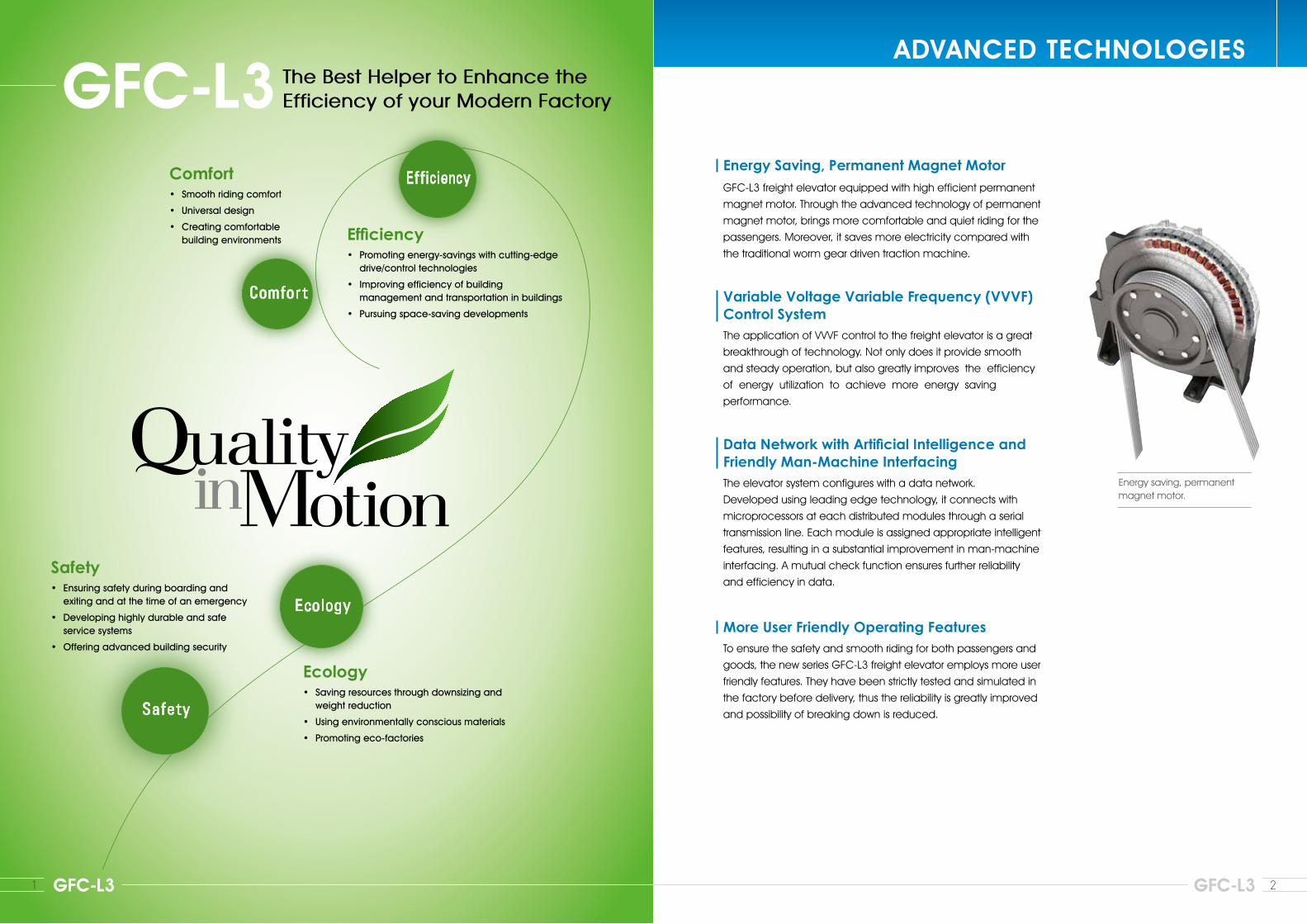
Energy Saving, Permanent Magnet MotorGFC-L3 freight elevator equipped with high efficient permanent
magnet motor. Through the advanced technology of permanent
magnet motor, brings more comfortable and quiet riding for the
passengers. Moreover, it saves more electricity compared with
the traditional worm gear driven traction machine.
Variable Voltage Variable Frequency (VVVF) Control SystemThe application of VVVF control to the freight elevator is a great
breakthrough of technology. Not only does it provide smooth
and steady operation, but also greatly improves the efficiency
of energy utilization to achieve more energy saving
performance.
Data Network with Artificial Intelligence and Friendly Man-Machine InterfacingThe elevator system configures with a data network.
Developed using leading edge technology, it connects with
microprocessors at each distributed modules through a serial
transmission line. Each module is assigned appropriate intelligent
features, resulting in a substantial improvement in man-machine
interfacing. A mutual check function ensures further reliability
and efficiency in data.
More User Friendly Operating FeaturesTo ensure the safety and smooth riding for both passengers and
goods, the new series GFC-L3 freight elevator employs more user
friendly features. They have been strictly tested and simulated in
the factory before delivery, thus the reliability is greatly improved
and possibility of breaking down is reduced.
Ecology • Savingresourcesthroughdownsizingandweightreduction
• Usingenvironmentallyconsciousmaterials
• Promotingeco-factories
Energy saving, permanent magnet motor.
1 GFC-L3
3 4GFC-L3 GFC-L3
CAR DESIGNS ENTRANCE DESIGNS
Elevator color shown is slightly different from actual tone. Elevator color shown is slightly different from actual tone.
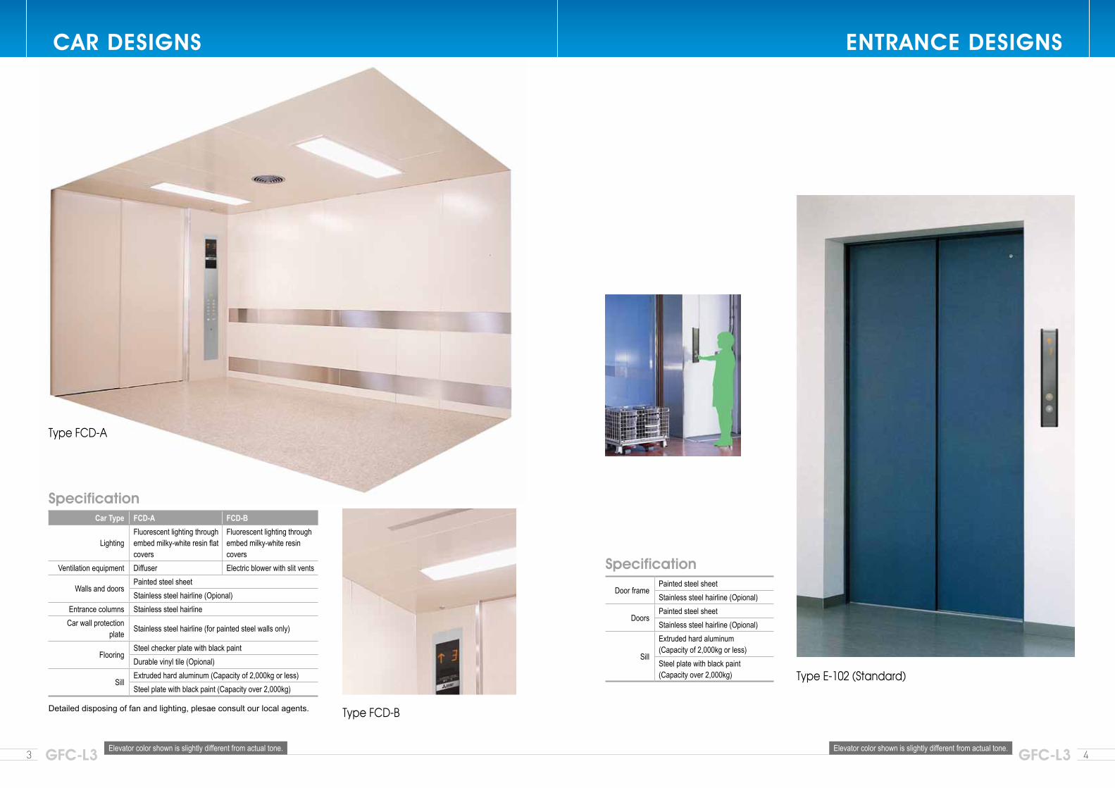
Type FCD-B
Type E-102 (Standard)
Type FCD-A
Car Type FCD-A FCD-B
LightingFluorescent lighting through embed milky-white resin flat covers
Fluorescent lighting through embed milky-white resin covers
Ventilation equipment Diffuser Electric blower with slit vents
Walls and doorsPainted steel sheetStainless steel hairline (Opional)
Entrance columns Stainless steel hairlineCar wall protection
plate Stainless steel hairline (for painted steel walls only)
FlooringSteel checker plate with black paintDurable vinyl tile (Opional)
SillExtruded hard aluminum (Capacity of 2,000kg or less)Steel plate with black paint (Capacity over 2,000kg)
Door framePainted steel sheetStainless steel hairline (Opional)
DoorsPainted steel sheetStainless steel hairline (Opional)
Sill
Extruded hard aluminum (Capacity of 2,000kg or less)Steel plate with black paint (Capacity over 2,000kg)
Specification
Specification
Detailed disposing of fan and lighting, plesae consult our local agents.
False Call Canceling-Car Button Type (FCC-P)If the wrong car button is pressed, it can be canceled by quickly pressing the same button
again twice.
Non-Service to Specific Floors-Car Button Type (NS-CB) [Optional]
To enhance security, service to specific floors can be disabled using the car operating
panel. This function is automatically deactivated during emergency operation.
Repeated Door-Close (RDC)Should an obstacle prevent the doors from closing, the doors will repeatedly open and
close until the obstacle is cleared from the doorway.
Extended Door-Open Button (DKO-TB)When the button inside a car is pressed, the doors will remain open longer to allow loading
and unloading of baggage, a stretcher, etc.
Door Load Detector (DLD)When excessive door load has been detected while opening or closing, the doors
immediately reverse.
Mitsubishi Emergency Landing Device (MELD) [Optional]
Upon power failure, a car equipped with this function automatically moves and stops at the
nearest floor using a rechargeable battery, and the doors open to ensure passenger safety.
(Maximum allowable floor-to-floor distance is 10 meters.)
(MELD is only applied bellow: 750~1000 kg 60~105 m/min, 1500~2500 kg 45~105 m/min.)
* See page 21-24 for details of other features.5 6GFC-L3 GFC-L3
FINISH COLORS AND PATTERNS FEATURES FOR PRODUCTS
FOR COMFORT,CONVENIENCE AND SAFETY
Color shown is slightly different from actual tone.
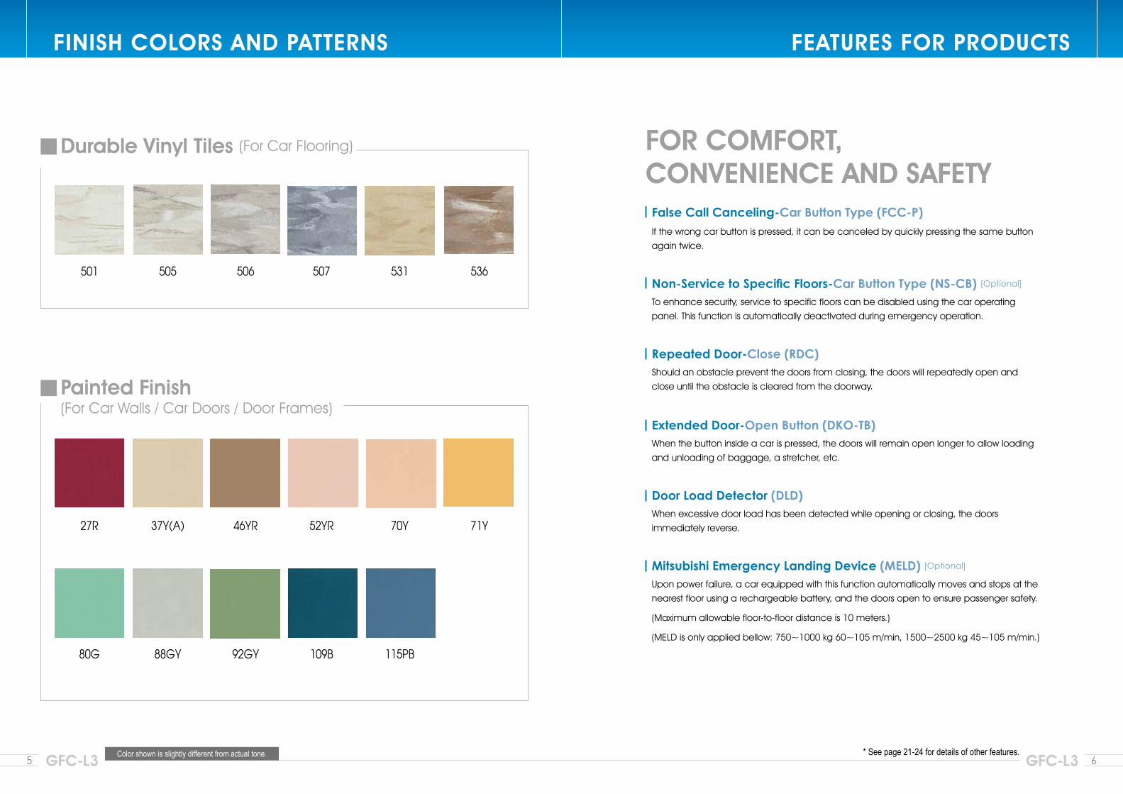
Durable Vinyl Tiles (For Car Flooring)
Painted Finish (For Car Walls / Car Doors / Door Frames)
501
27R
80G
505
37Y(A)
88GY
506
46YR
92GY
507
52YR
109B
531
70Y
115PB
536
71Y
7 8GFC-L3 GFC-L3
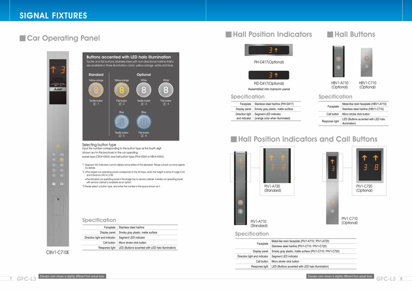
SIGNAL FIXTURES
CBV1-C710E
Selecting button typeInput the number corresponding to the button type as the fourth digit(shown as # in this brochure) in the car operatingpanel type (CBV#-XXXX) and hall button type (PIV#-XXXX or HBV#-XXXX).
*1 Segment LED indicators cannot display some letters of the alphabet. Please consult our local agents for details.
*2 •Thelargestcaroperatingpanelcorrespondstothe20stops,whentheheightissameofcage(CH) and Enteance (HH) in 2100.
•Thestandardcaroperatingpanelinthisimagehasnoservicecabinet.Asimilarcaroperatingpanelwithservicecabinetisavailableasanoption.
*3Pleaseselectabuttontype,andenterthenumberinthespaceshownas#.
PIH-D417(Optional)
HBV1-A710(Optional)
HBV1-C710(Optional)
PID-D417(Optional)
PIV1-A710(Standard)
PIV1-A720(Standard)
PIV1-C720(Optional)
PIV1-C710(Optional)
Elevator color shown is slightly different from actual tone. Elevator color shown is slightly different from actual tone.
Faceplate Stainless steel hairline Display panel Smoky gray plastic, matte surface
Direction light and indicator Segment LED indicatorCall button Micro stroke click button
Respones light LED (Buttons accented with LED halo illumination)
FaceplateMetal-like resin faceplate (HBV1-A710)Stainless steel hairline (HBV1-C710)
Call button Micro stroke click button
Respones light LED (Buttons accented with LED halo illumination)
Faceplate Stainless steel hairline (PIH-D417)Display panel Smoky gray plastic, matte surfaceDirection light and indicator
Segment LED indicator(orange color when illuminated)
Specification
SpecificationSpecification
Car Operating Panel Hall Position Indicators
Hall Position Indicators and Call Buttons
Hall Buttons
Assembled into transom panel
FaceplateMetal-like resin faceplate (PIV1-A710 / PIV1-A720)Stainless steel hairline (PIV1-C710 / PIV1-C720)
Display panel Smoky gray plastic, matte surface (PIV1-C710 / PIV1-C720)Direction light and indicator Segment LED indicator
Call button Micro stroke click buttonRespones light LED (Buttons accented with LED halo illumination)
Specification
Buttons accented with LED halo illuminationTactile and flat buttons (stainless-steel with non-directional hairline-finish) areavailableinthreeilluminationcolors:yellow-orange,whiteandblue.
Standard Optional
Yellow-orange Yellow-orange
Blue
White
Blue
White
Tactile button : 1
Flat button : 2
Tactile button : 5
Tactile button : 3
Flat button : 6
Flat button : 4
R6
R5
R4
R1
R2
R3
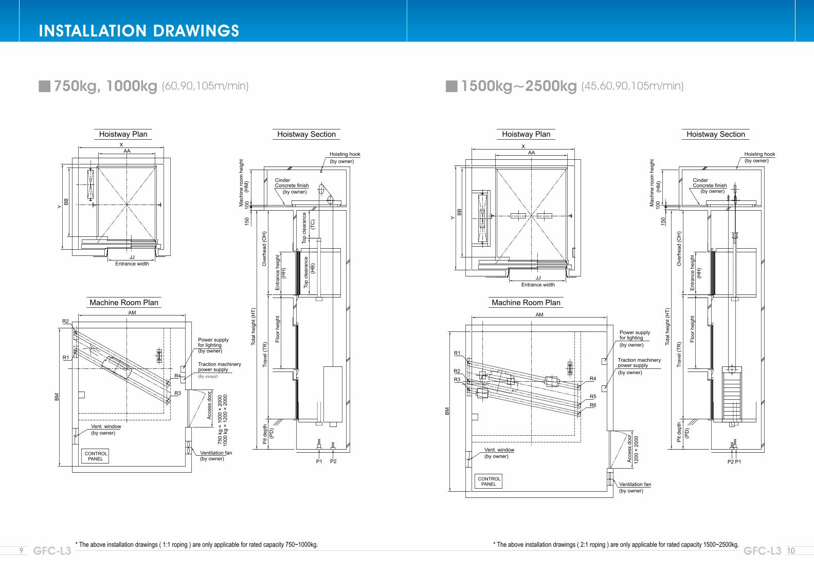
* The above installation drawings ( 2:1 roping ) are only applicable for rated capacity 1500~2500kg.* The above installation drawings ( 1:1 roping ) are only applicable for rated capacity 750~1000kg.
CONTROL PANEL
AM
Acc
ess
door
1200
× 2
000
BM
Power supplyfor lighting(by owner)
Traction machinerypower supply(by owner)
Ventilation fan(by owner)
Vent. window(by owner)
JJ
BB
AAX
Y
Entrance width
F750~100060~105m/min
F1500~250045~105m/min
JJ
BB
AAX
Y
Entrance width
CONTROL PANEL
Acc
ess
door
750
kg =
100
0 ×
2000
1000
kg
= 12
00 ×
200
0
Ventilation fan(by owner)
Power supplyfor lighting(by owner)
Traction machinerypower supply
R4
R3
AM
BM
R2
R1
Vent. window(by owner)
(by owner)
Top
clea
ranc
eTo
p cl
eara
nce
100
P1 P2
Pit
dept
hTr
avel
(TR
)O
verh
ead
(OH
)
Floo
r hei
ght
Ent
ranc
e he
ight
Tota
l hei
ght (
HT)
(HH
)
Hoisting hook(by owner)
Cinder Concrete finish
(by owner)
Mac
hine
room
hei
ght
(HM
)
(PD
)
150
(HB
)(T
C)
100
P1P2
Pit
dept
hTr
avel
(TR
)O
verh
ead
(OH
)
Floo
r hei
ght
Ent
ranc
e he
ight
Tota
l hei
ght (
HT)
(HH
)
Hoisting hook(by owner)
Mac
hine
room
hei
ght
(HM
)
(PD
)
150
Cinder Concrete finish
(by owner)
R6
R5
R4
R1
R2
R3
* The above installation drawings ( 2:1 roping ) are only applicable for rated capacity 1500~2500kg.* The above installation drawings ( 1:1 roping ) are only applicable for rated capacity 750~1000kg.
CONTROL PANEL
AM
Acc
ess
door
1200
× 2
000
BM
Power supplyfor lighting(by owner)
Traction machinerypower supply(by owner)
Ventilation fan(by owner)
Vent. window(by owner)
JJ
BB
AAX
Y
Entrance width
F750~100060~105m/min
F1500~250045~105m/min
JJ
BB
AAX
Y
Entrance width
CONTROL PANEL
Acc
ess
door
750
kg =
100
0 ×
2000
1000
kg
= 12
00 ×
200
0
Ventilation fan(by owner)
Power supplyfor lighting(by owner)
Traction machinerypower supply
R4
R3
AM
BM
R2
R1
Vent. window(by owner)
(by owner)
Top
clea
ranc
eTo
p cl
eara
nce
100
P1 P2
Pit
dept
hTr
avel
(TR
)O
verh
ead
(OH
)
Floo
r hei
ght
Ent
ranc
e he
ight
Tota
l hei
ght (
HT)
(HH
)
Hoisting hook(by owner)
Cinder Concrete finish
(by owner)
Mac
hine
room
hei
ght
(HM
)
(PD
)
150
(HB
)(T
C)
100
P1P2
Pit
dept
hTr
avel
(TR
)O
verh
ead
(OH
)
Floo
r hei
ght
Ent
ranc
e he
ight
Tota
l hei
ght (
HT)
(HH
)
Hoisting hook(by owner)
Mac
hine
room
hei
ght
(HM
)
(PD
)
150
Cinder Concrete finish
(by owner)
* The above installation drawings ( 1:1 roping ) are only applicable for rated capacity 750~1000kg. * The above installation drawings ( 2:1 roping ) are only applicable for rated capacity 1500~2500kg.9 10GFC-L3 GFC-L3
INSTALLATION DRAWINGS
750kg, 1000kg (60,90,105m/min) 1500kg~2500kg (45,60,90,105m/min)
11 12GFC-L3 GFC-L3
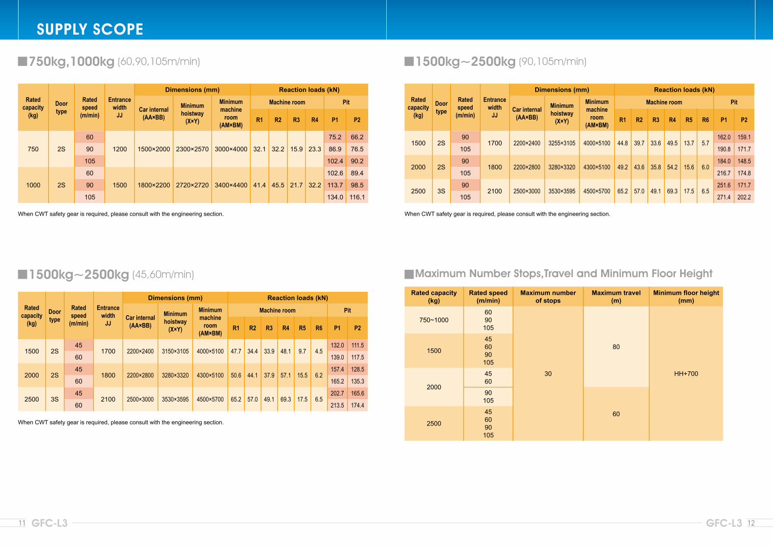
SUPPLY SCOPE
1500kg~2500kg (90,105m/min)
Ratedcapacity
(kg)
Doortype
Rated speed
(m/min)
Entrancewidth
JJ
Dimensions (mm) Reaction loads (kN)
Car internal(AA×BB)
Minimumhoistway
(X×Y)
Minimummachine
room(AM×BM)
Machine room Pit
R1 R2 R3 R4 R5 R6 P1 P2
1500 2S90
1700 2200×2400 3255×3105 4000×5100 44.8 39.7 33.6 49.5 13.7 5.7162.0 159.1
105 190.8 171.7
2000 2S90
1800 2200×2800 3280×3320 4300×5100 49.2 43.6 35.8 54.2 15.6 6.0184.0 148.5
105 216.7 174.8
2500 3S90
2100 2500×3000 3530×3595 4500×5700 65.2 57.0 49.1 69.3 17.5 6.5251.6 171.7
105 271.4 202.2
When CWT safety gear is required, please consult with the engineering section.
Maximum Number Stops,Travel and Minimum Floor Height
Rated capacity(kg)
Rated speed(m/min)
Maximum numberof stops
Maximum travel(m)
Minimum floor height(mm)
750~10006090
105
30
80
HH+700
1500
456090
105
2000
4560
90105
602500
456090
105
750kg,1000kg (60,90,105m/min)
Ratedcapacity
(kg)
Doortype
Rated speed
(m/min)
Entrancewidth
JJ
Dimensions (mm) Reaction loads (kN)
Car internal(AA×BB)
Minimumhoistway
(X×Y)
Minimummachine
room(AM×BM)
Machine room Pit
R1 R2 R3 R4 P1 P2
750 2S
60
1200 1500×2000 2300×2570 3000×4000 32.1 32.2 15.9 23.3
75.2 66.2
90 86.9 76.5
105 102.4 90.2
1000 2S
60
1500 1800×2200 2720×2720 3400×4400 41.4 45.5 21.7 32.2
102.6 89.4
90 113.7 98.5
105 134.0 116.1
When CWT safety gear is required, please consult with the engineering section.
Ratedcapacity
(kg)
Doortype
Rated speed
(m/min)
Entrancewidth
JJ
Dimensions (mm) Reaction loads (kN)
Car internal(AA×BB)
Minimumhoistway
(X×Y)
Minimummachine
room(AM×BM)
Machine room Pit
R1 R2 R3 R4 R5 R6 P1 P2
1500 2S45
1700 2200×2400 3150×3105 4000×5100 47.7 34.4 33.9 48.1 9.7 4.5132.0 111.5
60 139.0 117.5
2000 2S45
1800 2200×2800 3280×3320 4300×5100 50.6 44.1 37.9 57.1 15.5 6.2157.4 128.5
60 165.2 135.3
2500 3S45
2100 2500×3000 3530×3595 4500×5700 65.2 57.0 49.1 69.3 17.5 6.5202.7 165.6
60 213.5 174.4
1500kg~2500kg (45,60m/min)
When CWT safety gear is required, please consult with the engineering section.
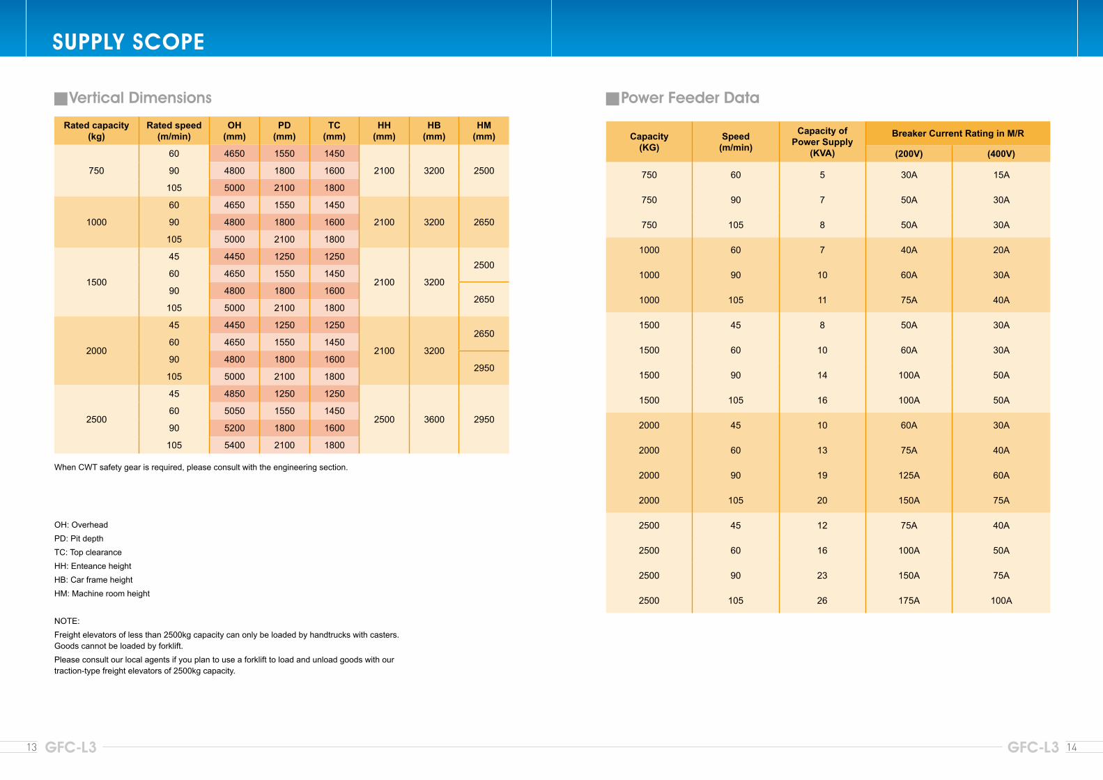
Capacity(KG)
Speed(m/min)
Capacity of Power Supply
(KVA)
Breaker Current Rating in M/R
(200V) (400V)
750 60 5 30A 15A
750 90 7 50A 30A
750 105 8 50A 30A
1000 60 7 40A 20A
1000 90 10 60A 30A
1000 105 11 75A 40A
1500 45 8 50A 30A
1500 60 10 60A 30A
1500 90 14 100A 50A
1500 105 16 100A 50A
2000 45 10 60A 30A
2000 60 13 75A 40A
2000 90 19 125A 60A
2000 105 20 150A 75A
2500 45 12 75A 40A
2500 60 16 100A 50A
2500 90 23 150A 75A
2500 105 26 175A 100A
13 14GFC-L3 GFC-L3
Power Feeder Data
SUPPLY SCOPE
OH: OverheadPD: Pit depthTC: Top clearanceHH: Enteance heightHB: Car frame heightHM: Machine room height
NOTE:Freight elevators of less than 2500kg capacity can only be loaded by handtrucks with casters. Goods cannot be loaded by forklift.Please consult our local agents if you plan to use a forklift to load and unload goods with our traction-type freight elevators of 2500kg capacity.
Vertical Dimensions
Rated capacity(kg)
Rated speed(m/min)
OH(mm)
PD(mm)
TC(mm)
HH(mm)
HB(mm)
HM(mm)
750
60 4650 1550 1450
2100 3200 250090 4800 1800 1600
105 5000 2100 1800
1000
60 4650 1550 1450
2100 3200 265090 4800 1800 1600
105 5000 2100 1800
1500
45 4450 1250 1250
2100 3200
250060 4650 1550 1450
90 4800 1800 16002650
105 5000 2100 1800
2000
45 4450 1250 1250
2100 3200
265060 4650 1550 1450
90 4800 1800 16002950
105 5000 2100 1800
2500
45 4850 1250 1250
2500 3600 295060 5050 1550 1450
90 5200 1800 1600
105 5400 2100 1800
When CWT safety gear is required, please consult with the engineering section.
15 16GFC-L3 GFC-L3
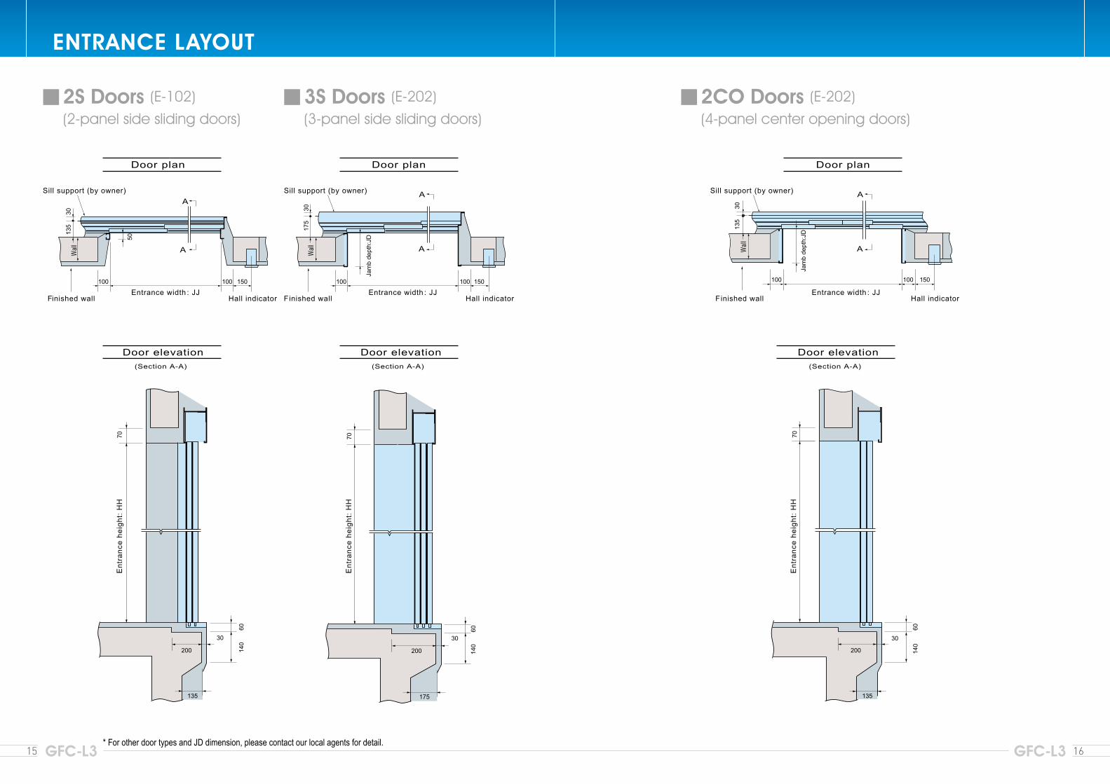
ENTRANCE LAYOUT
* For other door types and JD dimension, please contact our local agents for detail.
2S Doors (E-102) (2-panel side sliding doors)
3S Doors (E-202) (3-panel side sliding doors)
2CO Doors (E-202) (4-panel center opening doors)
17 18GFC-L3 GFC-L3
FEATURES
Feature Description
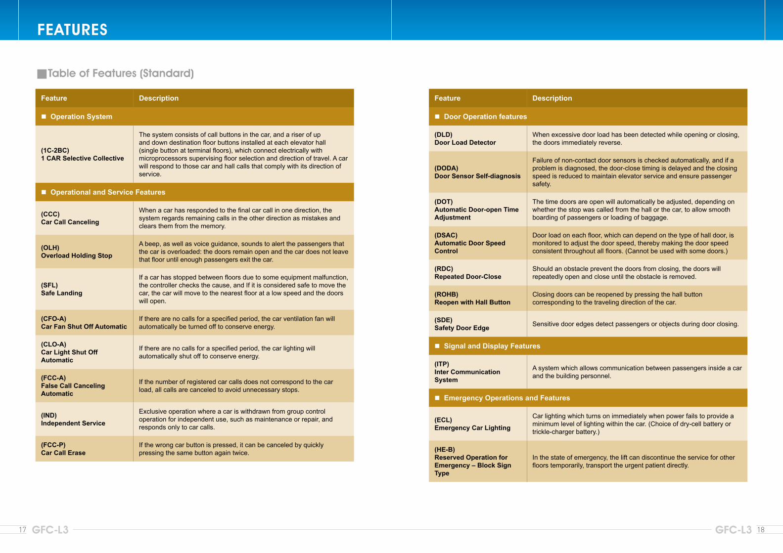
Operation System
(1C-2BC)1 CAR Selective Collective
The system consists of call buttons in the car, and a riser of up and down destination floor buttons installed at each elevator hall (single button at terminal floors), which connect electrically with microprocessors supervising floor selection and direction of travel. A car will respond to those car and hall calls that comply with its direction of service.
Operational and Service Features
(CCC)Car Call Canceling
When a car has responded to the final car call in one direction, the system regards remaining calls in the other direction as mistakes and clears them from the memory.
(OLH)Overload Holding Stop
A beep, as well as voice guidance, sounds to alert the passengers that the car is overloaded: the doors remain open and the car does not leave that floor until enough passengers exit the car.
(SFL)Safe Landing
If a car has stopped between floors due to some equipment malfunction, the controller checks the cause, and If it is considered safe to move the car, the car will move to the nearest floor at a low speed and the doors will open.
(CFO-A)Car Fan Shut Off Automatic
If there are no calls for a specified period, the car ventilation fan will automatically be turned off to conserve energy.
(CLO-A)Car Light Shut Off Automatic
If there are no calls for a specified period, the car lighting will automatically shut off to conserve energy.
(FCC-A)False Call Canceling Automatic
If the number of registered car calls does not correspond to the car load, all calls are canceled to avoid unnecessary stops.
(IND)Independent Service
Exclusive operation where a car is withdrawn from group control operation for independent use, such as maintenance or repair, and responds only to car calls.
(FCC-P)Car Call Erase
If the wrong car button is pressed, it can be canceled by quickly pressing the same button again twice.
Table of Features (Standard)
Feature Description
Door Operation features
(DLD)Door Load Detector
When excessive door load has been detected while opening or closing, the doors immediately reverse.
(DODA)Door Sensor Self-diagnosis
Failure of non-contact door sensors is checked automatically, and if a problem is diagnosed, the door-close timing is delayed and the closing speed is reduced to maintain elevator service and ensure passenger safety.
(DOT)Automatic Door-open Time Adjustment
The time doors are open will automatically be adjusted, depending on whether the stop was called from the hall or the car, to allow smooth boarding of passengers or loading of baggage.
(DSAC)Automatic Door Speed Control
Door load on each floor, which can depend on the type of hall door, is monitored to adjust the door speed, thereby making the door speed consistent throughout all floors. (Cannot be used with some doors.)
(RDC)Repeated Door-Close
Should an obstacle prevent the doors from closing, the doors will repeatedly open and close until the obstacle is removed.
(ROHB)Reopen with Hall Button
Closing doors can be reopened by pressing the hall button corresponding to the traveling direction of the car.
(SDE)Safety Door Edge Sensitive door edges detect passengers or objects during door closing.
Signal and Display Features
(ITP)Inter Communication System
A system which allows communication between passengers inside a car and the building personnel.
Emergency Operations and Features
(ECL)Emergency Car Lighting
Car lighting which turns on immediately when power fails to provide a minimum level of lighting within the car. (Choice of dry-cell battery or trickle-charger battery.)
(HE-B)Reserved Operation for Emergency – Block Sign Type
In the state of emergency, the lift can discontinue the service for other floors temporarily, transport the urgent patient directly.
Feature Description
Operational and Service Features
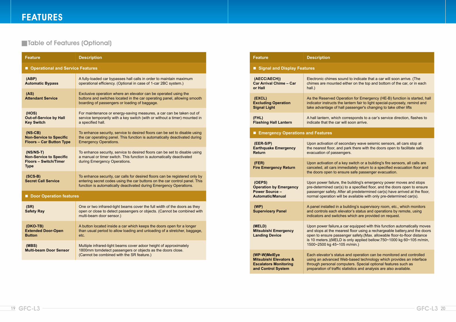
(ABP)Automatic Bypass
A fully-loaded car bypasses hall calls in order to maintain maximum operational efficiency. (Optional in case of 1-car 2BC system.)
(AS)Attendant Service
Exclusive operation where an elevator can be operated using the buttons and switches located in the car operating panel, allowing smooth boarding of passengers or loading of baggage.
(HOS)Out-of-Service by Hall Key Switch
For maintenance or energy-saving measures, a car can be taken out of service temporarily with a key switch (with or without a timer) mounted in a specified hall.
(NS-CB)Non-Service to Specific Floors – Car Button Type
To enhance security, service to desired floors can be set to disable using the car operating panel. This function is automatically deactivated during Emergency Operations.
(NS/NS-T)Non-Service to Specific Floors – Switch/Timer Type
To enhance security, service to desired floors can be set to disable using a manual or timer switch. This function is automatically deactivated during Emergency Operations.
(SCS-B)Secret Call Service
To enhance security, car calls for desired floors can be registered only by entering secret codes using the car buttons on the car control panel. This function is automatically deactivated during Emergency Operations.
Door Operation features
(SR)Safety Ray
One or two infrared-light beams cover the full width of the doors as they open or close to detect passengers or objects. (Cannot be combined with multi-beam door sensor.)
(DKO-TB)Extended Door-Open Button
A button located inside a car which keeps the doors open for a longer than usual period to allow loading and unloading of a stretcher, baggage, etc.
(MBS)Multi-beam Door Sensor
Multiple infrared-light beams cover adoor height of approximately 1800mm tomdetect passengers or objects as the doors close.(Cannot be combined with the SR feature.)
Feature Description
Signal and Display Features
(AECC/AECH))Car Arrival Chime – Car or Hall
Electronic chimes sound to indicate that a car will soon arrive. (The chimes are mounted either on the top and bottom of the car, or in each hall.)
(EXCL)Excluding Operation Signal Light
As the Reserved Operation for Emergency (HE-B) function is started, hall indicator instructs the lantern fair to light special-purposely, remind and take advantage of hall passenger's changing to take other lifts
(FHL)Flashing Hall Lantern
A hall lantern, which corresponds to a car’s service direction, flashes to indicate that the car will soon arrive.
Emergency Operations and Features
(EER-S/P)Earthquake Emergency Return
Upon activation of secondary wave seismic sensors, all cars stop at the nearest floor, and park there with the doors open to facilitate safe evacuation of passengers.
(FER)Fire Emergency Return
Upon activation of a key switch or a building's fire sensors, all calls are canceled, all cars immediately return to a specified evacuation floor and the doors open to ensure safe passenger evacuation.
(OEPS)Operation by Emergency Power Source – Automatic/Manual
Upon power failure, the building's emergency power moves and stops pre-determined car(s) to a specified floor, and the doors open to ensure passenger safety. After all predetermined car(s) have arrived at the floor, normal operation will be available with only pre-determined car(s).
(WP)Superviosry Panel
A panel installed in a building’s supervisory room, etc., which monitors and controls each elevator’s status and operations by remote, using indicators and switches which are provided on request.
(MELD)Mitsubishi Emergency Landing Device
Upon power failure,a car equipped with this function automatically moves and stops at the mearest floor using a rechargeable battery,and the doors open to ensure passenger safety.(Max. allowable floor-to-floor distance is 10 meters.)(MELD is only applied bellow:750~1000 kg 60~105 m/min, 1500~2500 kg 45~105 m/min.)
(WP-W)MelEyeMitsubishi Elevators & Escalators Monitoring and Control System
Each elevator’s status and operation can be monitored and controlled using an advanced Web-based technology which provides an interface through personal computers. Special optional features such as preparation of traffic statistics and analysis are also available.
19 20GFC-L3 GFC-L3
FEATURES
Table of Features (Optional)
21 22GFC-L3 GFC-L3
MEMONOTES ON INSTALLANTION PLANNING
Elevator Site Requirements• The temperature of the machine room and elevator shall be below 40°C.• The following conditions are required for maintaining elevator performance.
a. The relative humidity shall be below 90% on a monthly average and below 95% on a daily average.b. The machine room and the elevator hoistway shall be free of dust or harmful gas.c. The walls, floors, and ceiling of the machine room shall be finished with mortar or other materials so as to prevent
concerte dust.• Voltage fluctuation shall be with in a range of +5% to -10%.
Work Not Included in Elevator ContractThe following items are excluded from Mitsubishi Electric’s elevator installation work, and are therefore the responsibility of the building owner or general contractor:• Construction of the elevator machine room with proper beams and slabs, equipped with a lock, complete with
illumination, ventilation, and waterproofing.• Access to the elevator machine room sufficient to allow passage of the control panel and traction machine.
Suspension hook facilities and ladders in the machine room.• Architectural finishing of the machine-room floor and the walls and floors in the vicinity of the entrance hall after
installation has been completed.• Construction of an illuminated, ventilated, and waterproofed elevator hoistway.• A ladder to the elevator pit.• Provision for the cutting of necessary holes and joists and for making good thereafter as required.• Separate beams, when the hoistway dimensions markedly exceed the specifications, and intermediate beams when
two or more elevators are installed.• All other work related to building construction.• The machine-room power-receiving panel and the elevator wiring for illumination, plus the power from them to the
electrical room.• The laying of conduits and wiring between the elevator pit and the terminating point for the devices installed outside
the hoistway, such as the emergency bell, intercom, monitoring and security devices,etc.• The power consumed in installation work and test operation.• All the necessary buiding materials for grouting in of bracktes, bolts, etc.• The test provision and subsequent alteration as required, and eventual removal of the scaffolding as required by the
elevator contractor, and any protection of the work as may be required during progress.• The provision of a suitable, locked space for the storage of elevator equipment and tools during elevator installation.• The security system, such as a card reader, connected to Mitsubishi Electric’s elevator controller, when supplied by the
building owner or general contractor.
* Work responsibilities in installation and construction shall be determined according to the local laws.Please consult our local agents for details.
Ordering InformationPlease include the following information when ordering or requesting estimates:• The desired number of units, speed, and loading capacity.• The number of stops or number of floors to be served.• The total elevator travel and floor-to floor height.• Operation system.• Selected design and size of car.• Entrance design.• Signal equipment.• A sketch of part of the building where the elevators are to be installed.• The voltage, number of phases, and frequency of the power source for the motor and lighting.

![Mer for optimum allocation accross investment alternatives [autosaved]-gfc-office-gfc-office-gfc-office-gfc-office](https://img.pdfslide.us/doc/110x75/58e91bcf1a28ab6e0e8b5dbd/mer-for-optimum-allocation-accross-investment-alternatives-autosaved-gfc-office-gfc-office-gfc-office-gfc-office.jpg)


![naruto 458 colo [GFC]](https://img.pdfslide.us/doc/110x75/568c3b971a28ab0235aab512/naruto-458-colo-gfc.jpg)