Embed Size (px)
Citation preview

Advanced statistical techniques for spectrum engineering analysis
SEAMCAT: a European experience
European Communications Office
Jean-Philippe Kermoal - SEAMCAT Manager (ECO)
ISART – May 12, 2015
EUROPEAN COMMUNICATIONS OFFICE
Nansensgade 19 DK-1366 Copenhagen Denmark
Telephone: + 45 33 89 63 00 Telefax: + 45 33 89 63 30
E-mail: [email protected] Web Site: http://www.cept.org/eco
Jean-Philippe Kermoal / ECO Page 2
Agenda

Jean-Philippe Kermoal / ECO Page 3
Advanced Statistical Techniques for Spectrum Engineering Analysis
A SEAMCAT view
European Communications Office
Jean-Philippe Kermoal - SEAMCAT Manager (ECO)
ISART – May 12, 2015
EUROPEAN COMMUNICATIONS OFFICE
Nansensgade 19 DK-1366 Copenhagen Denmark
Telephone: + 45 33 89 63 00 Telefax: + 45 33 89 63 30
E-mail: [email protected] Web Site: http://www.cept.org/eco
Jean-Philippe Kermoal / ECO Page 4
Outline Introduction to SEAMCAT
Jean-Philippe Kermoal / ECO Page 5
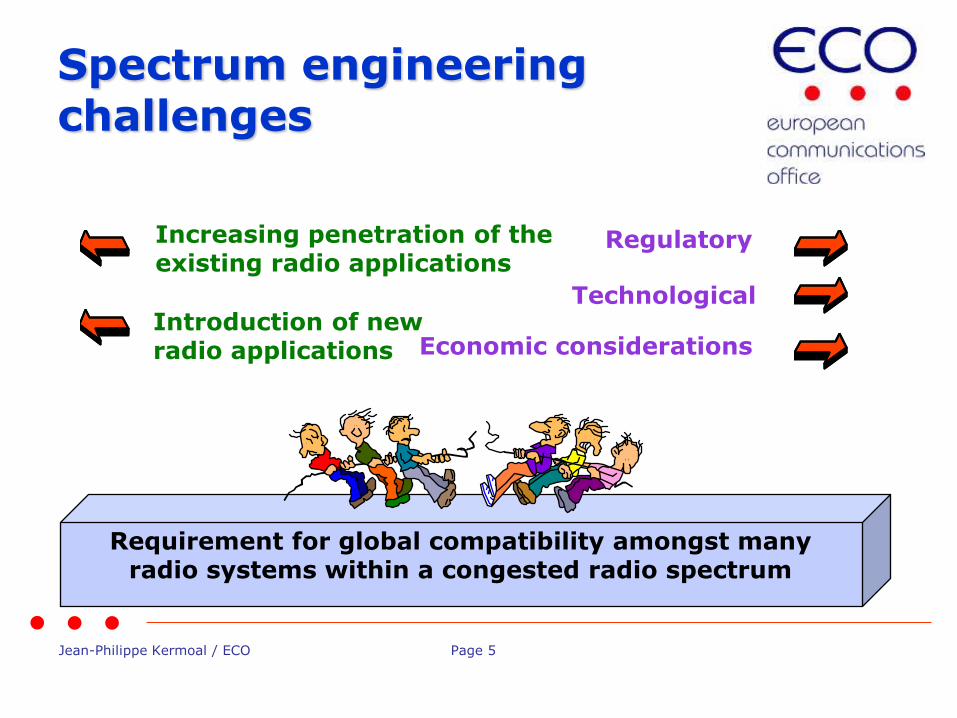
Spectrum engineering challenges
Requirement for global compatibility amongst many radio systems within a congested radio spectrum
Introduction of new radio applications
Technological
Regulatory
Economic considerations
Increasing penetration of the existing radio applications

Jean-Philippe Kermoal / ECO Page 6
Spectrum engineering challenges
Requirement for global compatibility amongst many radio systems within a congested radio spectrum
Introduction of new radio applications
Technological
Regulatory
Economic considerations
Increasing penetration of the existing radio applications
Jean-Philippe Kermoal / ECO Page 7
• There are no more “empty” spectrum
• Proposed new systems have to find way of “sharing” with some of existing systems
• Thus the need for spectrum engineering and optimisation:
– to find which existing radio systems are easiest to share with, and then
– determine the “sharing rules”
Need for spectrum sharing

Jean-Philippe Kermoal / ECO Page 8
• There are no more “empty” spectrum
• Proposed new systems have to find way of “sharing” with some of existing systems
• Thus the need for spectrum engineering and optimisation:
– to find which existing radio systems are easiest to share with, and then
– determine the “sharing rules”
Need for spectrum sharing
Jean-Philippe Kermoal / ECO Page 9
• Spacing radio systems in frequency
– Using the gaps between existing channels
• Spacing geographically
– Using the gaps between intended deployment areas (e.g. cities vs. rural areas)
• Time sharing
– Exploiting different work time (day vs. night)
• Working at different power levels
– E.g. “underlay” spectrum use by UWB
Sharing methods
Jean-Philippe Kermoal / ECO Page 10
• Agile (cognitive) radio systems require minimum sharing rules as they could be adapting dynamically
– Simple example: finding free channel in a given geographic area
• Traditional rigid-design radio system will require precisely defined sharing rules
– Maximum transmit power, guard-bands to existing systems, etc
Sharing implementation
Jean-Philippe Kermoal / ECO Page 11
• Analytical analysis, usually by worst-case approach:
– Minimum Coupling Loss (MCL) method, to establish rigid rules for minimum “separation”
• Statistical analysis of random trials:
– The Monte-Carlo method, to establish probability of interference for a given realistic deployment scenario
– That is where SEAMCAT comes into picture!
Defining the sharing rules
Jean-Philippe Kermoal / ECO Page 12
SEAMCAT is not a CAT
SEAMCAT-4 Software tool

Jean-Philippe Kermoal / ECO Page 13
History
• Developed in CEPT as a co-operation between National Regulatory Administrations, ECO and industry
• First released in Jan-2000, then gradually developed in several phases
• Latest version 4.1.0 (October 2013)
• Freely downloadable from ECO website (www.seamcat.org)
Jean-Philippe Kermoal / ECO Page 14
• SEAMCAT is designed for:
– Co-existence/sharing studies between different radio systems operating in same or adjacent frequency bands
– Any type of radio systems in terrestrial scenarios
– Extended to cellular system like CDMA and OFDMA
– Quantification of probability of interference between various radio systems
• Not designed for system planning purposes
• Limitated for time domain simulation (e.g. Colision probability), radar
Purpose
Jean-Philippe Kermoal / ECO Page 15
• Mobile:
– Land Mobile Systems
– Short Range Devices
– Earth based components of satellite systems
• Broadcasting:
– terrestrial systems
– DTH receivers of satellite systems
• Fixed:
– Point-to-Point and Point-to-Multipoint
... and more
Typical examples of modelled system
Jean-Philippe Kermoal / ECO Page 16
Strategic tool for CEPT (1)
• For performing compatibility/sharing studies
– Used in generating studies for ECC/CEPT Reports
• As a Reference tool
– Recognised at ITU (Rep. ITU-R SM.2028-1)
• For educating future generation of spectrum engineer (Administrations, Industry or University)

Jean-Philippe Kermoal / ECO Page 17
Strategic tool for CEPT (2)
• As an agreed work platform wthin CEPT
– CEPT Project Teams (technical experts) can focus on the input parameters and not on the algorithm
– Exchange of simulation workspaces between proponents eases the trust in the results
Jean-Philippe Kermoal / ECO Page 18
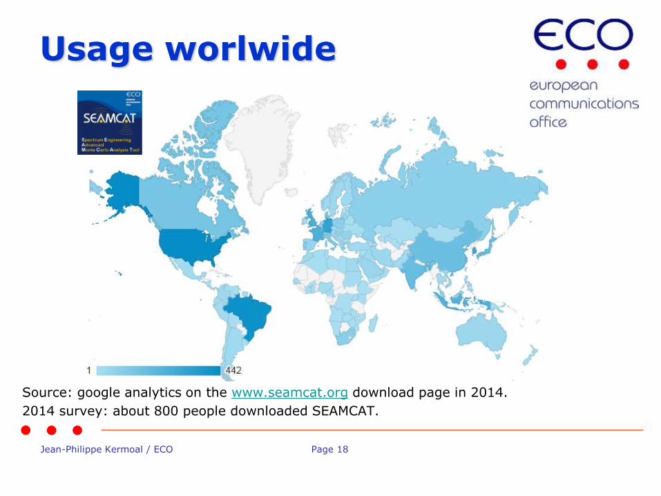
Usage worlwide
Source: google analytics on the www.seamcat.org download page in 2014.
2014 survey: about 800 people downloaded SEAMCAT.
Jean-Philippe Kermoal / ECO Page 19
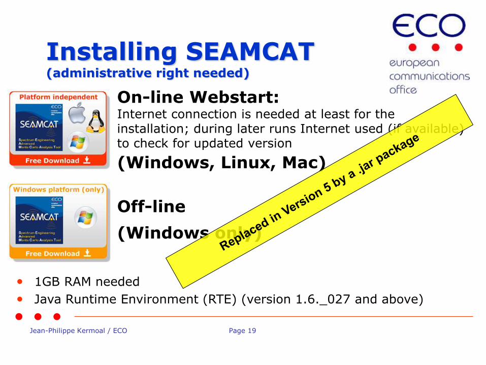
Installing SEAMCAT (administrative right needed)
On-line Webstart: Internet connection is needed at least for the installation; during later runs Internet used (if available) to check for updated version
Off-line
(Windows, Linux, Mac)
(Windows only)
• 1GB RAM needed
• Java Runtime Environment (RTE) (version 1.6._027 and above)
Jean-Philippe Kermoal / ECO Page 20
Conclusions
• Sharing rules are important element of spectrum optimisation process
• Unless some intelligent interference avoidance is implemented in radio systems, the careful choice of sharing conditions is the only means for achieving successful co-existence and optimal spectrum use
• Statistical tool SEAMCAT is a powerful tool for such analysis
• Strategic tool for the CEPT
• Reference tool – recognised at ITU
• World wide usage
• Free tool to run on any operating system platform

Jean-Philippe Kermoal / ECO Page 21
Thank you - Any questions?

Jean-Philippe Kermoal / ECO Page 22
Principle of Monte-Carlo in a SEAMCAT environment
European Communications Office
Jean-Philippe Kermoal - SEAMCAT Manager (ECO)
ISART – May 12, 2015
EUROPEAN COMMUNICATIONS OFFICE
Nansensgade 19 DK-1366 Copenhagen Denmark
Telephone: + 45 33 89 63 00 Telefax: + 45 33 89 63 30
E-mail: [email protected] Web Site: http://www.cept.org/eco
Jean-Philippe Kermoal / ECO Page 23
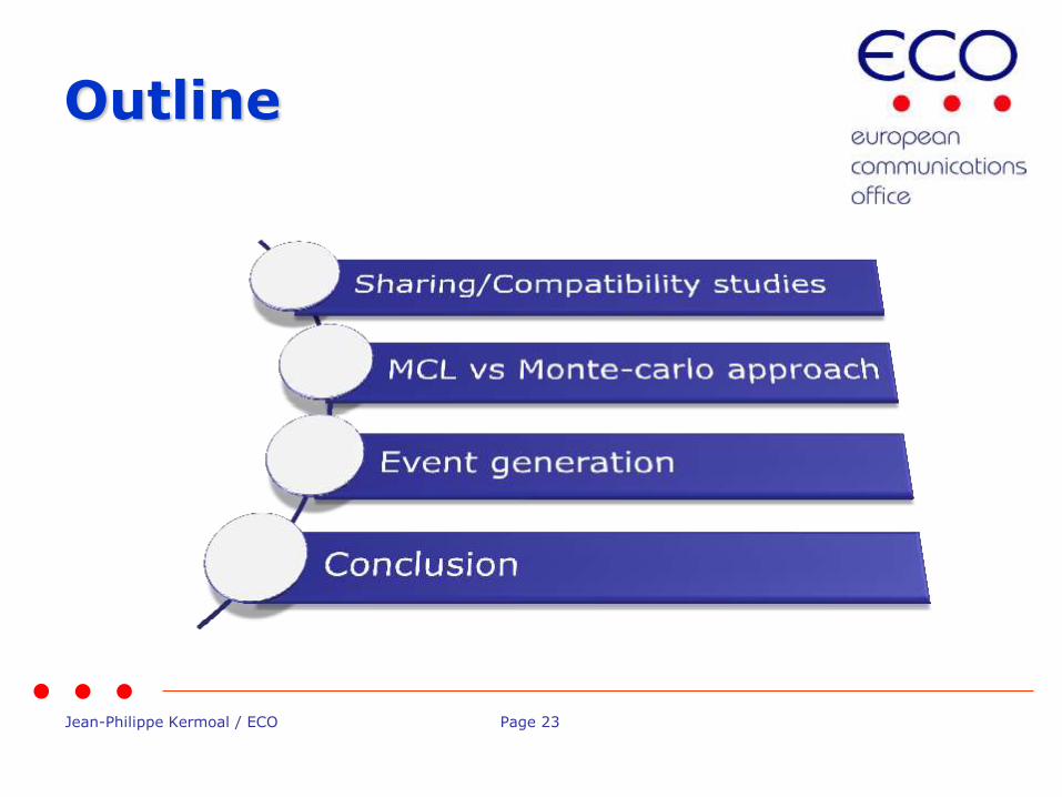
Outline
Jean-Philippe Kermoal / ECO Page 24
• Sharing: between different radio systems operating in the same frequency bands (ERC Report 68)
• Compatibility: between different radio systems operating in the adjacent frequency bands
• Interference criteria
• Analytical analysis: MCL (worse case)
• Statistical analysis: Monte-Carlo method
Sharing/compatibility studies

Jean-Philippe Kermoal / ECO Page 25
25
Coexistence between systems
Jean-Philippe Kermoal / ECO Page 26
26
Interference criteria
• Interference criteria are defined to ensure:
• Quality of service (reduce error transmission)
• Service continuity (remote link with rockets, space shuttle)
• Interference criteria defines the sharing condition.
Jean-Philippe Kermoal / ECO Page 27
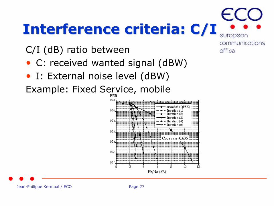
C/I (dB) ratio between
• C: received wanted signal (dBW)
• I: External noise level (dBW)
Example: Fixed Service, mobile
Interference criteria: C/I
Jean-Philippe Kermoal / ECO Page 28
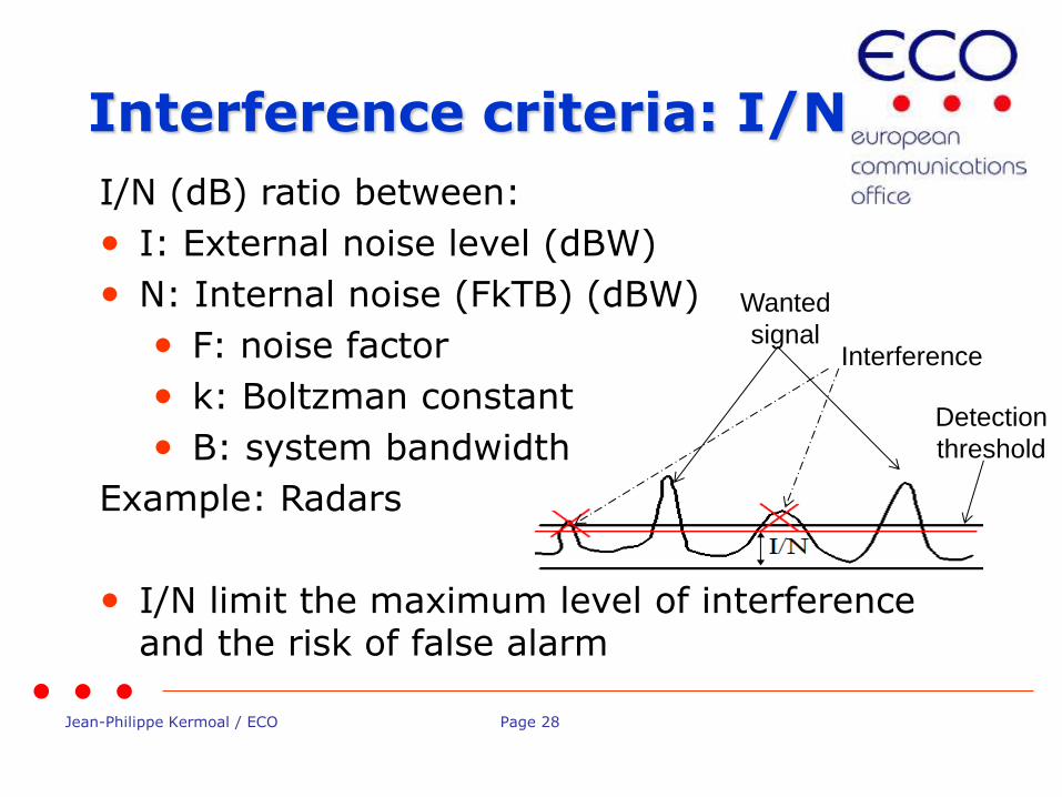
I/N (dB) ratio between:
• I: External noise level (dBW)
• N: Internal noise (FkTB) (dBW)
• F: noise factor
• k: Boltzman constant
• B: system bandwidth
Example: Radars
• I/N limit the maximum level of interference and the risk of false alarm
Interference criteria: I/N
Detection
threshold
Wanted
signal Interference
Jean-Philippe Kermoal / ECO Page 29
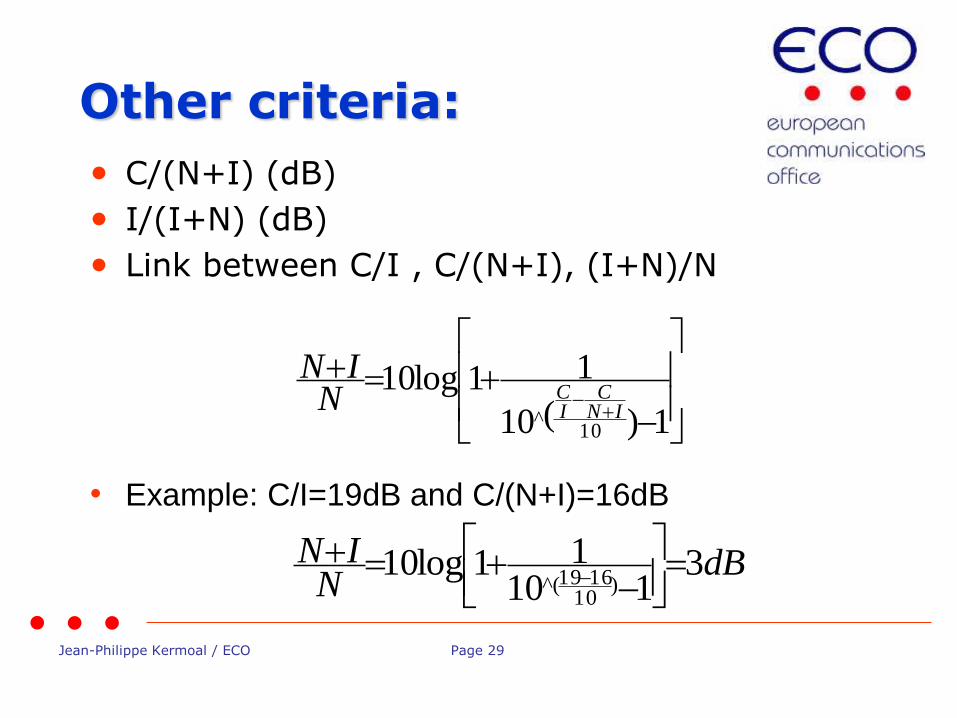
• C/(N+I) (dB)
• I/(I+N) (dB)
• Link between C/I , C/(N+I), (I+N)/N
• Example: C/I=19dB and C/(N+I)=16dB
Other criteria:
1)(10
11log10
10^ IN
CICN
IN
dBN
IN 3110
11log10)
101619(^

Jean-Philippe Kermoal / ECO Page 30
• Link between I/N and (N+I)/N
• Example: I/N=-6 dB
• But also, capacity loss or bit rate loss
Other criteria:
)(101log10 10^
NI
NIN
dBN
IN1)(^101log10 10
6
Jean-Philippe Kermoal / ECO Page 31
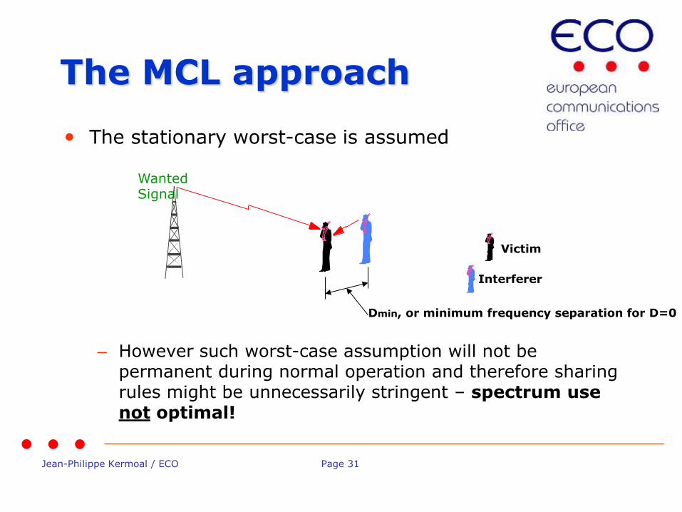
• The stationary worst-case is assumed
Wanted Signal
Victim
Interferer
Dmin, or minimum frequency separation for D=0
– However such worst-case assumption will not be permanent during normal operation and therefore sharing rules might be unnecessarily stringent – spectrum use not optimal!
The MCL approach
Jean-Philippe Kermoal / ECO Page 32
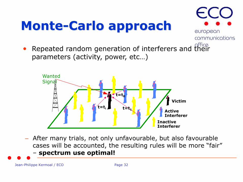
• Repeated random generation of interferers and their parameters (activity, power, etc…)
– After many trials, not only unfavourable, but also favourable cases will be accounted, the resulting rules will be more “fair” – spectrum use optimal!
Wanted Signal
Inactive Interferer
Victim
Active Interferer
t=t0
t=t1 t=ti
Monte-Carlo approach
Jean-Philippe Kermoal / ECO Page 33
• User will need to define the distributions of various input parameters, e.g.:
– How the power of interferer varies (Power Control?)
– How the interferer’s frequency channel varies
– How the distance between interferer and victim varies
– Etc..
• Number of trials has to be sufficiently high for statistical reliability:
– Not a problem with modern computers
Monte-Carlo Assumption
Jean-Philippe Kermoal / ECO Page 34
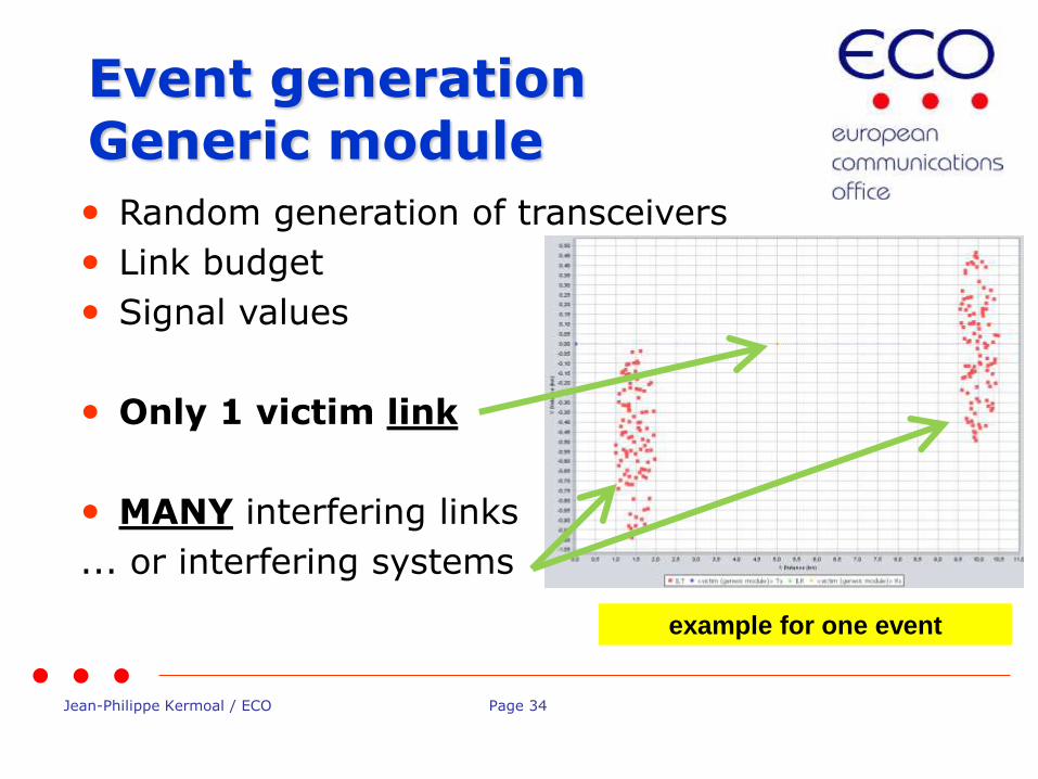
• Random generation of transceivers
• Link budget
• Signal values
• Only 1 victim link
• MANY interfering links
... or interfering systems
Event generation Generic module
example for one event
Jean-Philippe Kermoal / ECO Page 35
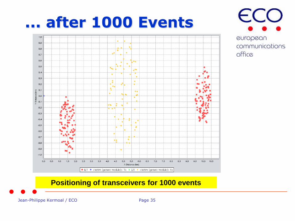
... after 1000 Events
Positioning of transceivers for 1000 events

Jean-Philippe Kermoal / ECO Page 36
• Succession of snapshots…
VLR
VLT
1) Calculate d, Ptx, GaTx, GaRx, L
2) Calculate dRSSi
dRSS
Snapshot# iRSS
Snapshot#
ILT
ILR
1) Calculate d, Ptx, GaTx, GaRx, L
2) Calculate received signal, if PC, adjust Ptx
1) Calculate d, Ptx, GaTx, GaRx, L
2) Calculate iRSSi VLR
VLT
ILT
ILR
How event generation works*
(*) Except CDMA/OFDMA systems

Jean-Philippe Kermoal / ECO Page 37
• Vectors for useful and interfering signals:
Results of event generation
dRSS
iRSS
Jean-Philippe Kermoal / ECO Page 38
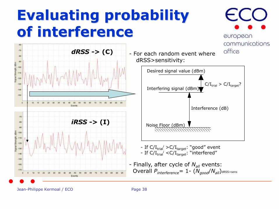
Evaluating probability of interference
- For each random event where dRSS>sensitivity:
Noise Floor (dBm)
Desired signal value (dBm)
Interfering signal (dBm) C/Itrial > C/Itarget?
Interference (dB)
- If C/Itriali >C/Itarget: “good” event
- If C/Itriali <C/Itarget: “interfered”
- Finally, after cycle of Nall events: Overall Pinterference= 1- (Ngood/Nall)dRSS>sens
dRSS -> (C)
iRSS -> (I)
Jean-Philippe Kermoal / ECO Page 39
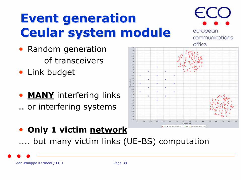
• Random generation
of transceivers
• Link budget
• MANY interfering links
.. or interfering systems
• Only 1 victim network
.... but many victim links (UE-BS) computation
Event generation Ceular system module
Jean-Philippe Kermoal / ECO Page 40
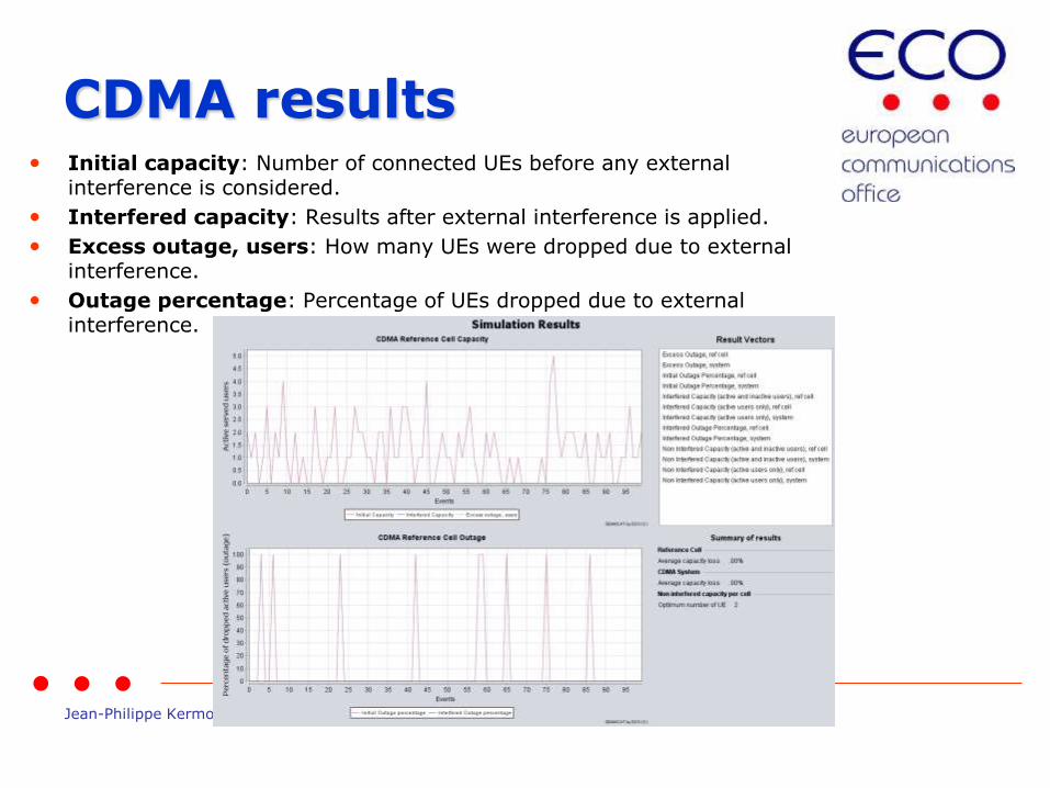
CDMA results • Initial capacity: Number of connected UEs before any external
interference is considered.
• Interfered capacity: Results after external interference is applied.
• Excess outage, users: How many UEs were dropped due to external interference.
• Outage percentage: Percentage of UEs dropped due to external interference.
Jean-Philippe Kermoal / ECO Page 41
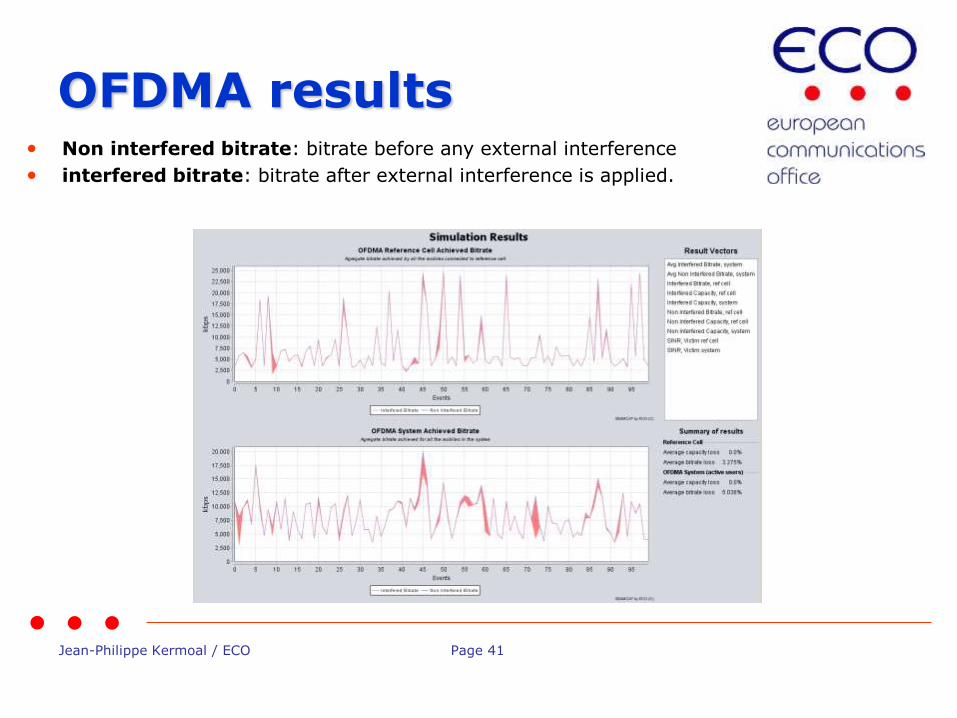
OFDMA results • Non interfered bitrate: bitrate before any external interference
• interfered bitrate: bitrate after external interference is applied.
Jean-Philippe Kermoal / ECO Page 42
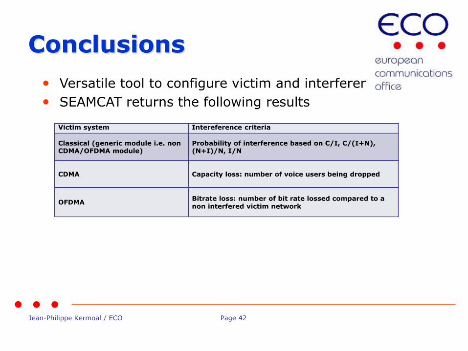
Conclusions
• Versatile tool to configure victim and interferer
• SEAMCAT returns the following results
Victim system Intereference criteria
Classical (generic module i.e. non CDMA/OFDMA module)
Probability of interference based on C/I, C/(I+N), (N+I)/N, I/N
CDMA Capacity loss: number of voice users being dropped
OFDMA Bitrate loss: number of bit rate lossed compared to a non interfered victim network
Jean-Philippe Kermoal / ECO Page 43
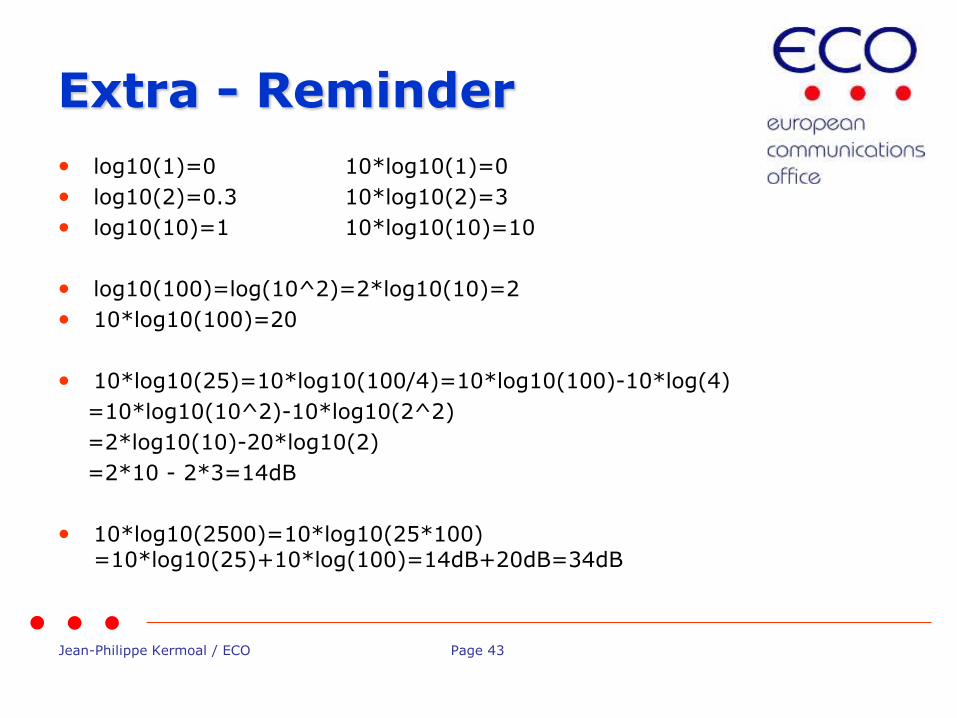
Extra - Reminder
• log10(1)=0 10*log10(1)=0
• log10(2)=0.3 10*log10(2)=3
• log10(10)=1 10*log10(10)=10
• log10(100)=log(10^2)=2*log10(10)=2
• 10*log10(100)=20
• 10*log10(25)=10*log10(100/4)=10*log10(100)-10*log(4)
=10*log10(10^2)-10*log10(2^2)
=2*log10(10)-20*log10(2)
=2*10 - 2*3=14dB
• 10*log10(2500)=10*log10(25*100) =10*log10(25)+10*log(100)=14dB+20dB=34dB

Jean-Philippe Kermoal / ECO Page 44
Thank you - Any questions?
Jean-Philippe Kermoal / ECO Page 45
A glance at the tool
EUROPEAN COMMUNICATIONS OFFICE
Nansensgade 19 DK-1366 Copenhagen Denmark
Telephone: + 45 33 89 63 00 Telefax: + 45 33 89 63 30
E-mail: [email protected] Web Site: http://www.cept.org/eco
European Communications Office
Jean-Philippe Kermoal - SEAMCAT Manager (ECO)
ISART – May 12, 2015
Jean-Philippe Kermoal / ECO Page 46
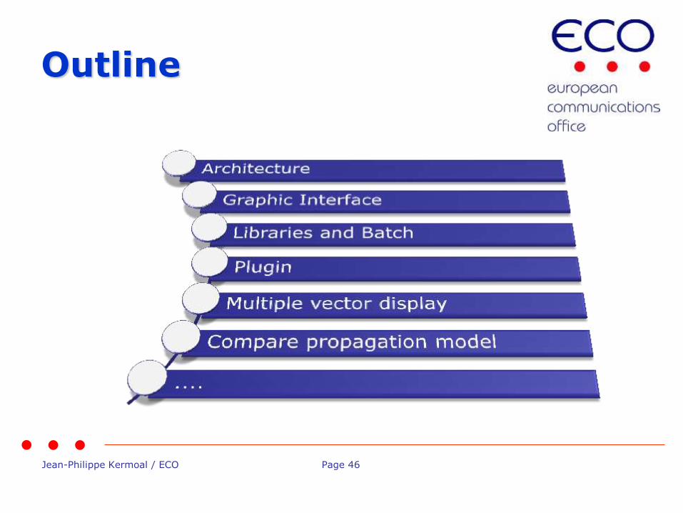
Outline

Jean-Philippe Kermoal / ECO Page 47
• Windows GUI - oriented
• Main element – workspace.sws
Main interface
Simulations input data – scenario: Equipment parameters, placement, propagations settings, etc.
Simulation controls: number of events etc..
Simulation results: dRSS/iRSS vectors, Pinterference, Cellular structure
Jean-Philippe Kermoal / ECO Page 48
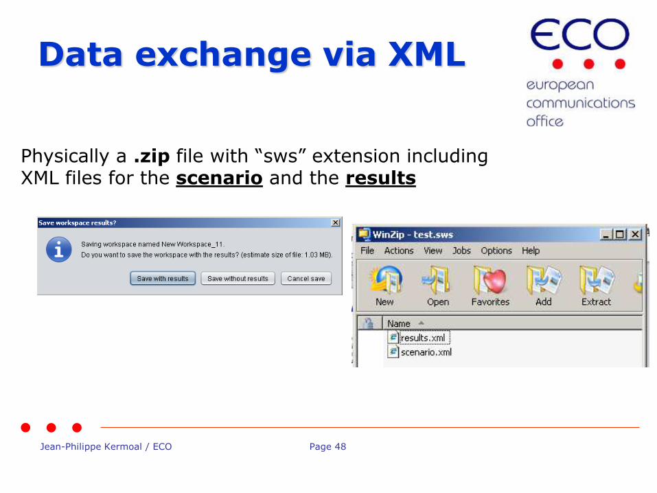
Data exchange via XML
Physically a .zip file with “sws” extension including XML files for the scenario and the results

Jean-Philippe Kermoal / ECO Page 49
Graphic interface (1/1)
View of parameters at a glance
Comparison of workpsaces
Graphical reminders (tooltip)
Jean-Philippe Kermoal / ECO Page 50
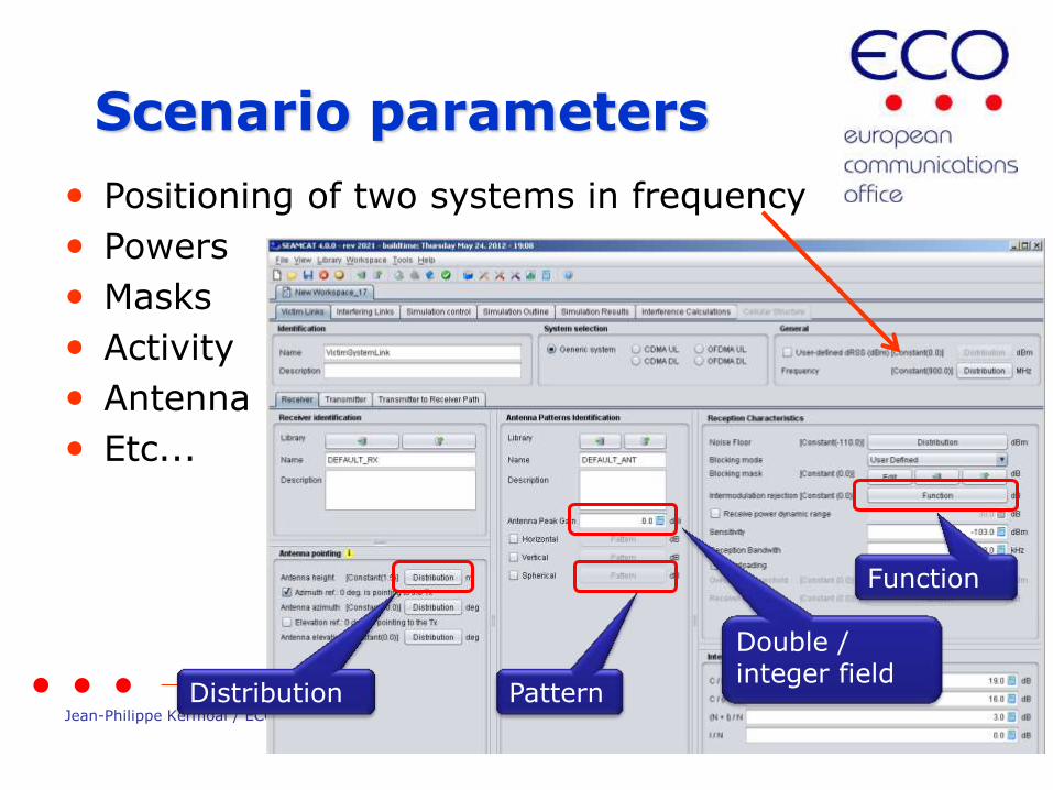
• Positioning of two systems in frequency
• Powers
• Masks
• Activity
• Antenna
• Etc...
Scenario parameters
Distribution Pattern
Double / integer field
Function

Jean-Philippe Kermoal / ECO Page 51
Graphic interface (1/2)
Shows positions and budget link information of the victim
and interfering systems
Overview of results (dRSS, iRSS)
Intuitive check of simulation scenario
Jean-Philippe Kermoal / ECO Page 52
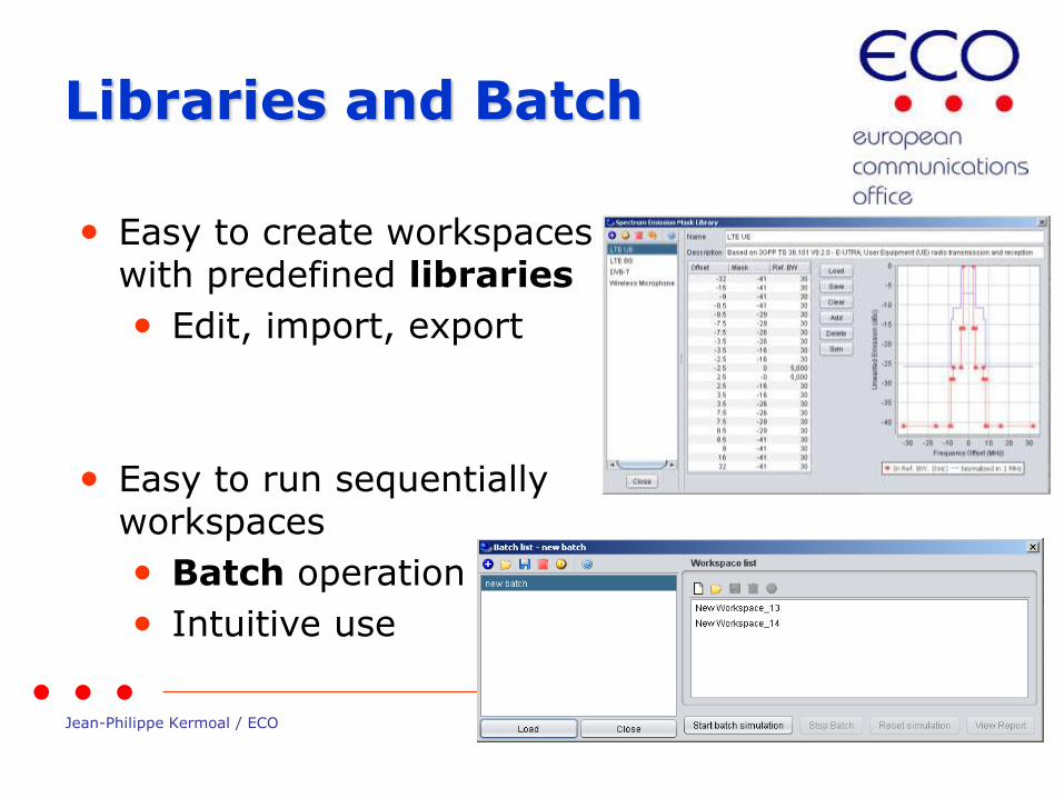
Libraries and Batch
• Easy to create workspaces with predefined libraries
• Edit, import, export
• Easy to run sequentially workspaces
• Batch operation
• Intuitive use
Jean-Philippe Kermoal / ECO Page 53
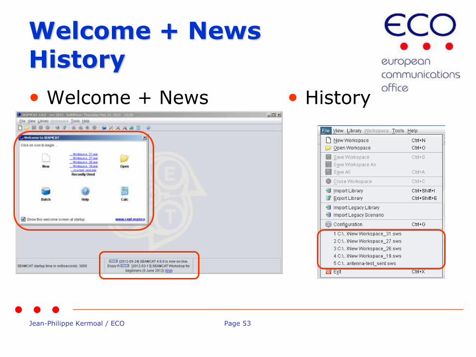
Welcome + News History
• Welcome + News • History

Jean-Philippe Kermoal / ECO Page 54
• This plug-in may be used to define ANY kind of propagation model
• The plug-in can replace a built-in model
• It is a software programme developed by YOU
• Use Java language, compile using open development tools
• Can be embedded to the workspace for sharing with others
• Examples (+ source code) available on the on-line manual.
Propagation model plug-in

Jean-Philippe Kermoal / ECO Page 55
Multiple vectors display
Calculated vectors or external vectors
Statistics and signal type
Jean-Philippe Kermoal / ECO Page 56
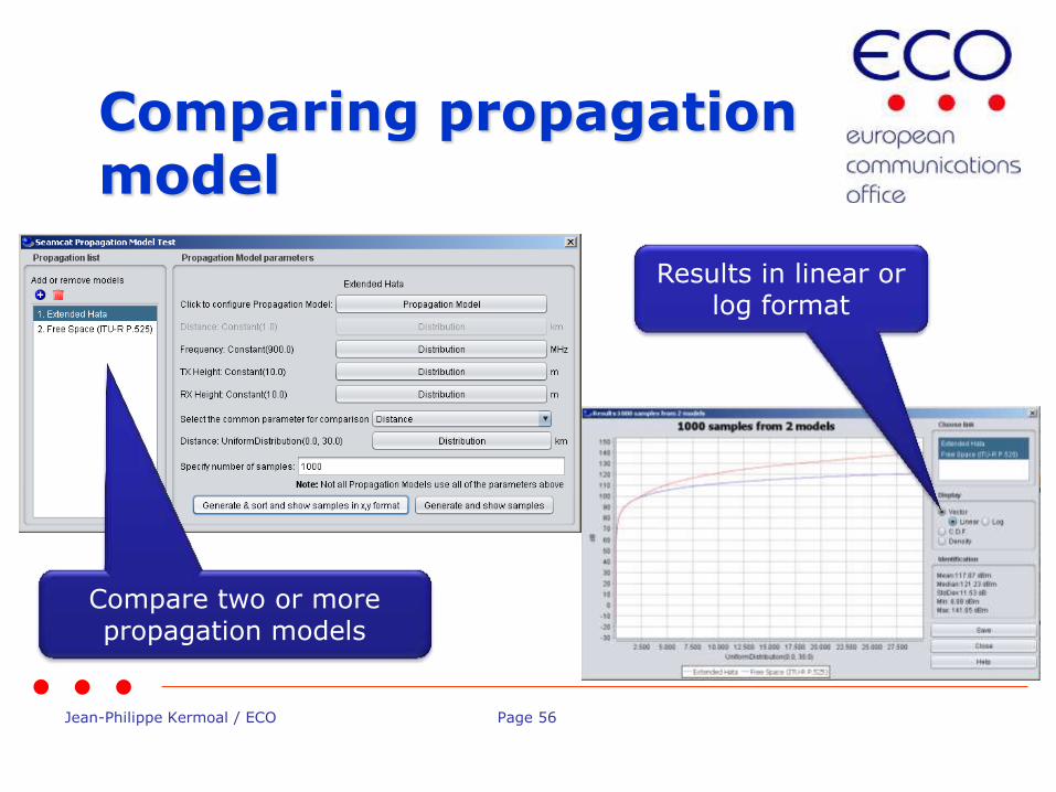
Comparing propagation model
Compare two or more propagation models
Results in linear or log format

Jean-Philippe Kermoal / ECO Page 57
Open source
• Open source in Java
• Source code available upon request
• 2 steps procedure:
1. License agreement to sign
2. Register to the “seamcat source code” group
Jean-Philippe Kermoal / ECO Page 58
Conclusions
• Simple architecture allowing any radio system to simulate
• XML data exchange
• Intuitive graphic interface
• Libraries and batch to help your daily SEAMCAT work
• Propagation model plugin interface
• World wide usage
Jean-Philippe Kermoal / ECO Page 59
Thank you - Any questions?
Jean-Philippe Kermoal / ECO Page 60
Modelling of Unwanted and Blocking
Interference Modes
European Communications Office
Jean-Philippe Kermoal
ISART – May 12, 2015
EUROPEAN COMMUNICATIONS OFFICE
Nansensgade 19 DK-1366 Copenhagen Denmark
Telephone: + 45 33 89 63 00 Telefax: + 45 33 89 63 30
E-mail: [email protected] Web Site: http://www.cept.org/eco
Jean-Philippe Kermoal / ECO Page 61
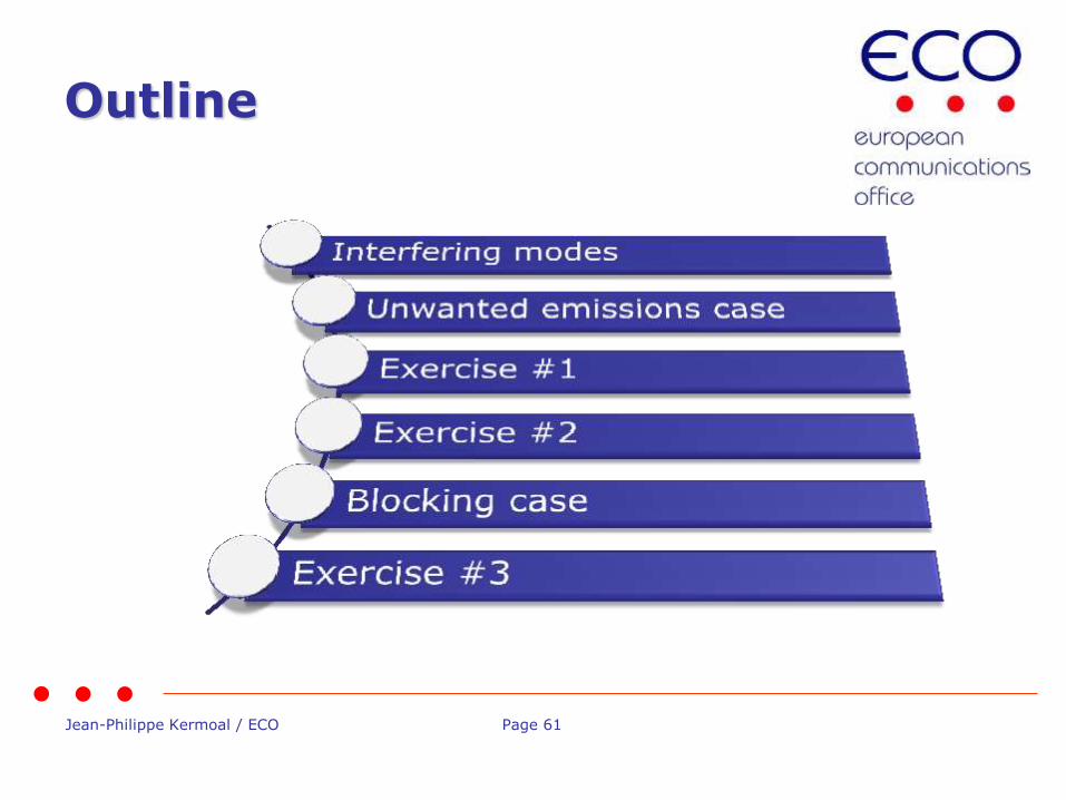
Outline
Jean-Philippe Kermoal / ECO Page 62
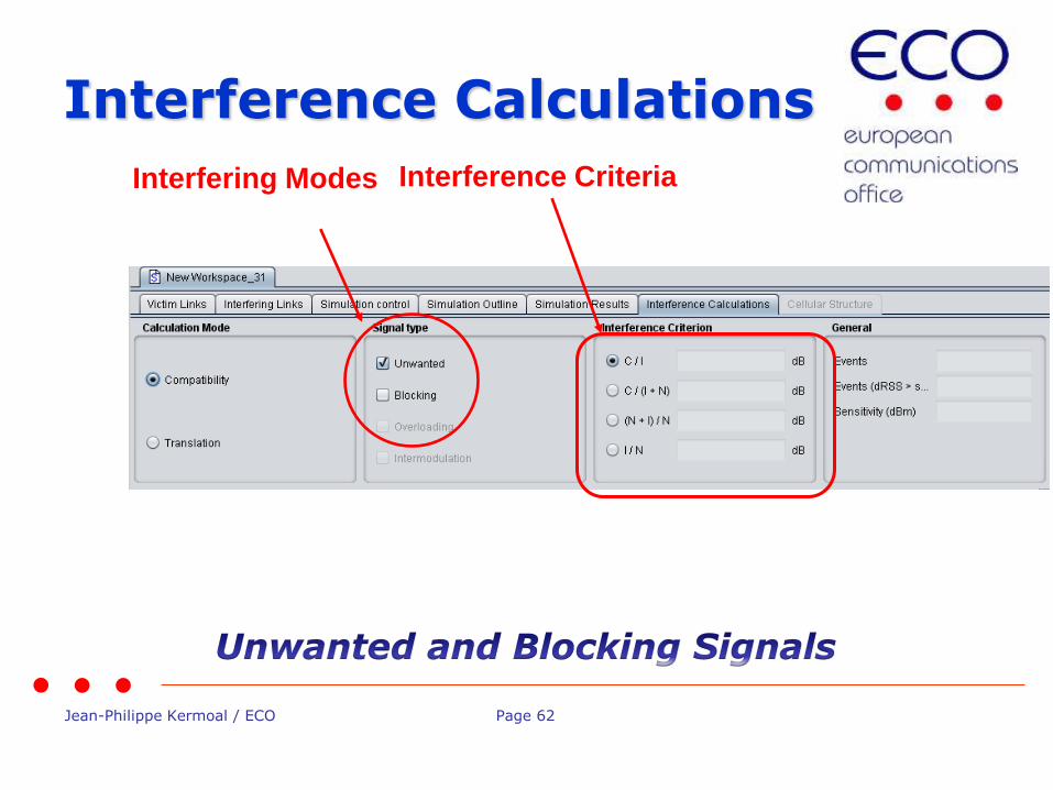
Interference Calculations
Interfering Modes Interference Criteria
Jean-Philippe Kermoal / ECO Page 63
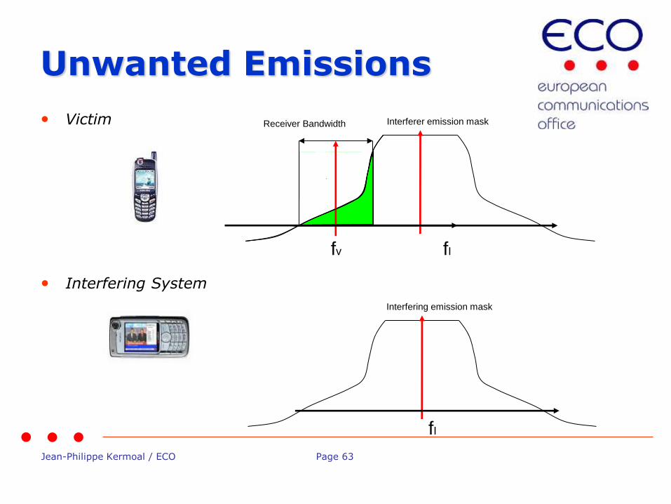
Unwanted Emissions
• Victim
fv
Receiver Bandwidth
• Interfering System
fI
Interfering emission mask
fI
Interferer emission mask

Jean-Philippe Kermoal / ECO Page 64
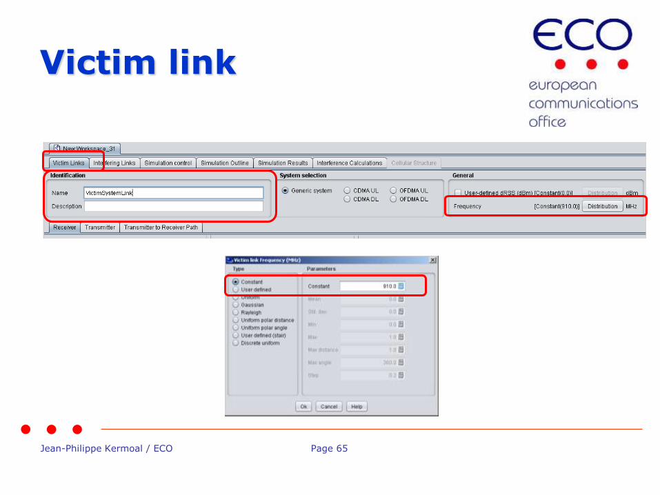
Exercise #1: Unwanted calculation
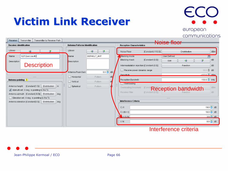
• Set victim link receiver (VLR) • Name: VLR Exercise #2
• Frequency: 910 MHz
• Interference criteria: I/N = 0
• Noise level = -110
• Bandwidth = 150 KHz
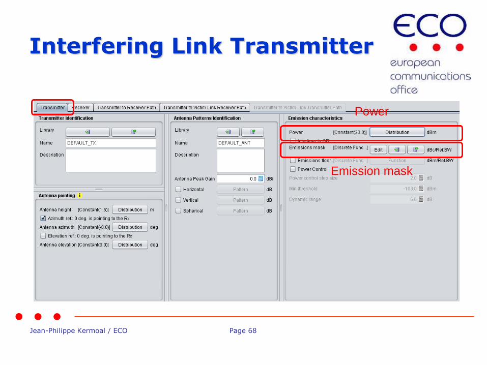
• Set interfering link transmitter (ILT) • Name: ILT Exercise #2
• Frequency: 905 MHz
• Power: 23 dBm
• Emission mask: default mask
• Path between VLR with ILT • Propagation model:free space (no variation)
• Position (x,y): fixed, 10km apart
Jean-Philippe Kermoal / ECO Page 65
Victim link
Jean-Philippe Kermoal / ECO Page 66
Victim Link Receiver
Interference criteria
Reception bandwidth
Description
Noise floor

Jean-Philippe Kermoal / ECO Page 67
Interfering Link
Jean-Philippe Kermoal / ECO Page 68
Interfering Link Transmitter
Power
Emission mask

Jean-Philippe Kermoal / ECO Page 69
Unwanted emissions mask
Default value
erroneous value
See the following
presentations...
Jean-Philippe Kermoal / ECO Page 70
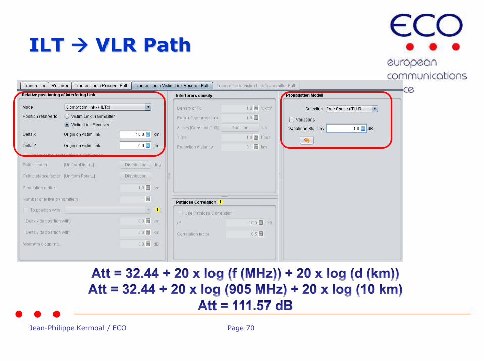
ILT VLR Path
Jean-Philippe Kermoal / ECO Page 71
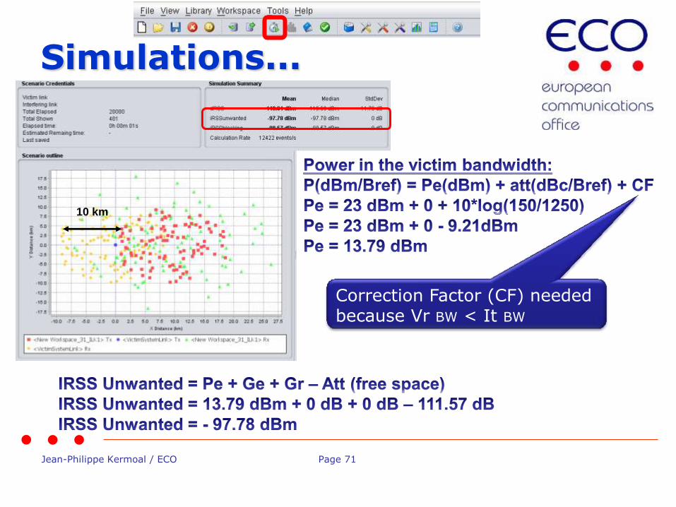
Simulations...
10 km
Correction Factor (CF) needed because Vr BW < It BW
Jean-Philippe Kermoal / ECO Page 72
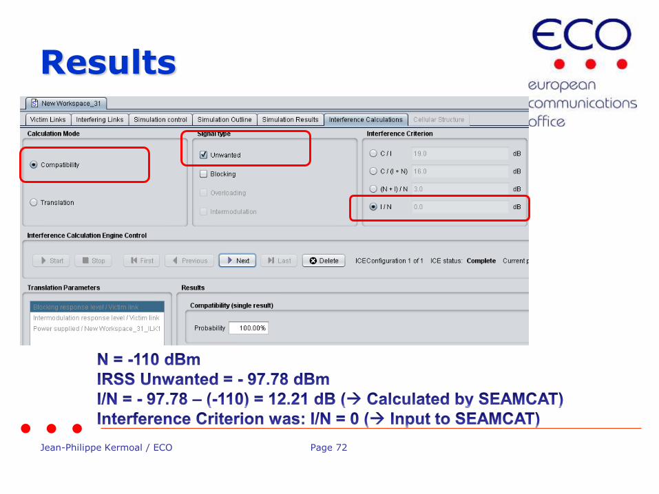
Results
Jean-Philippe Kermoal / ECO Page 73
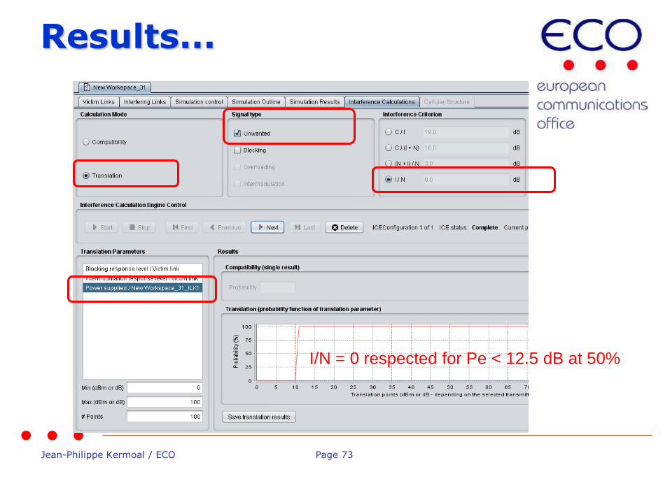
Results...
I/N = 0 respected for Pe < 12.5 dB at 50%
Jean-Philippe Kermoal / ECO Page 74
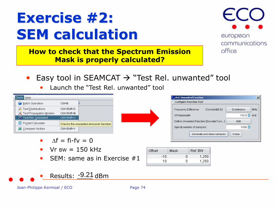
Exercise #2: SEM calculation
• Easy tool in SEAMCAT “Test Rel. unwanted” tool • Launch the “Test Rel. unwanted” tool
• Df = fi-fv = 0
• Vr BW = 150 kHz
• SEM: same as in Exercise #1
• Results: ____ dBm
How to check that the Spectrum Emission Mask is properly calculated?
-9.21
Jean-Philippe Kermoal / ECO Page 75
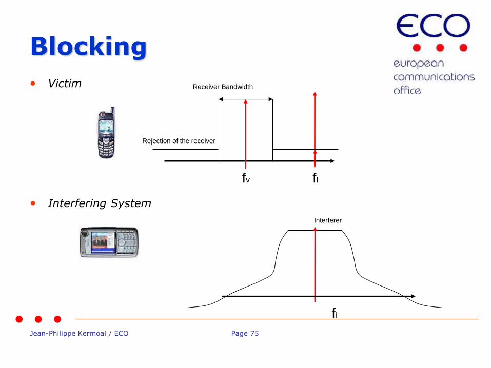
Blocking
• Victim
fv
Receiver Bandwidth
• Interfering System
fI
Interferer
fI
Rejection of the receiver
Jean-Philippe Kermoal / ECO Page 76
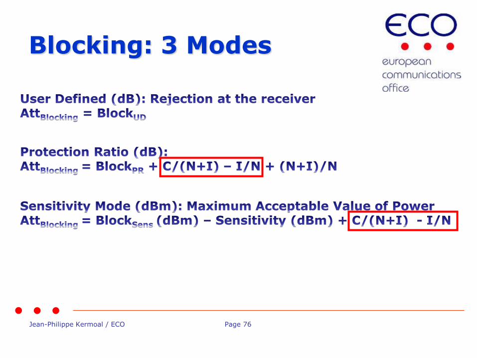
Blocking: 3 Modes
Jean-Philippe Kermoal / ECO Page 77
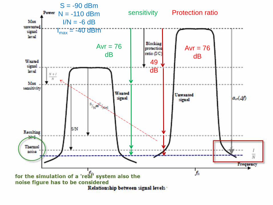
S = -90 dBm
N = -110 dBm
I/N = -6 dB
Imax = -40 dBm
sensitivity
Avr = 76
dB
Protection ratio
49
dB
Avr = 76
dB

Jean-Philippe Kermoal / ECO Page 78
Exercise # 3: blocking calculation
• Set victim link receiver (VLR) • Blocking mode: user defined
• Blocking response: function
(Load the ”example of a blocking mask.txt” file)
• Interference criteria: I/N = 0
• Noise level = -110
• Set interfering link transmitter (ILT) • No change
• Path between VLR with ILT • No change

Jean-Philippe Kermoal / ECO Page 79
Victim link
Jean-Philippe Kermoal / ECO Page 80
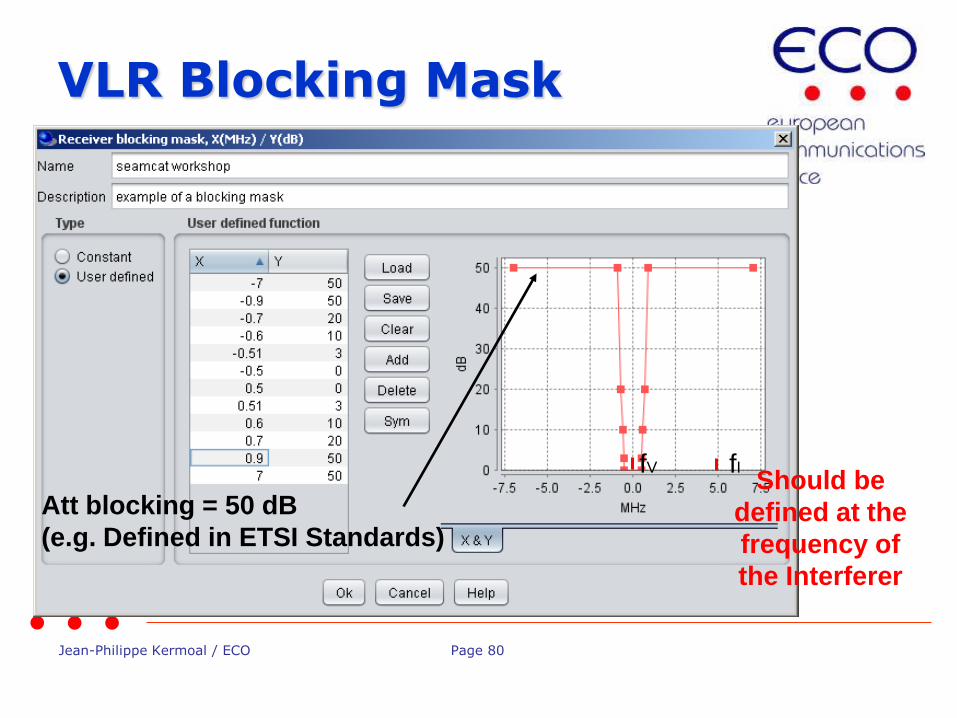
VLR Blocking Mask
Should be
defined at the
frequency of
the Interferer
Att blocking = 50 dB
(e.g. Defined in ETSI Standards)
fV fI

Jean-Philippe Kermoal / ECO Page 81
Simulations
Jean-Philippe Kermoal / ECO Page 82
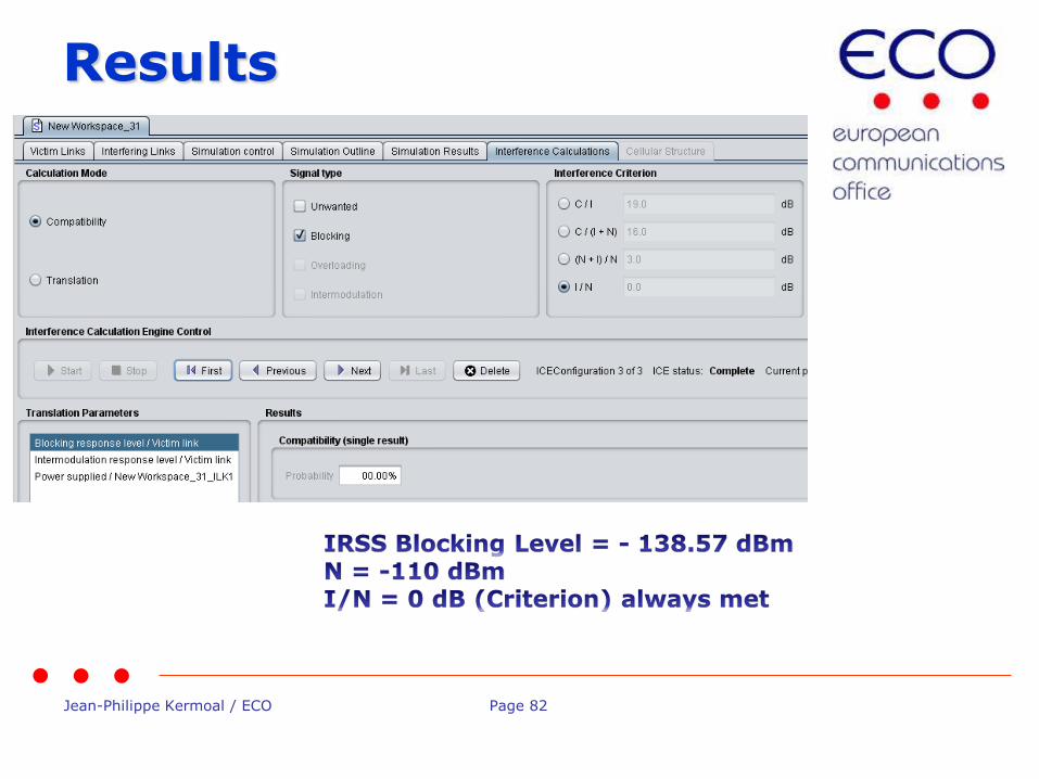
Results
Jean-Philippe Kermoal / ECO Page 83
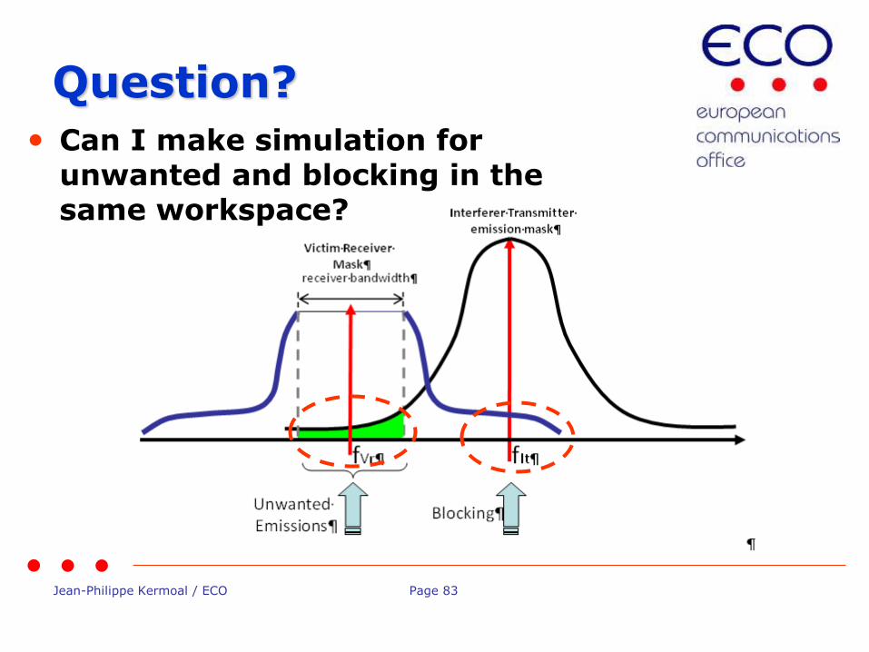
Question?
• Can I make simulation for unwanted and blocking in the same workspace?
Jean-Philippe Kermoal / ECO Page 84
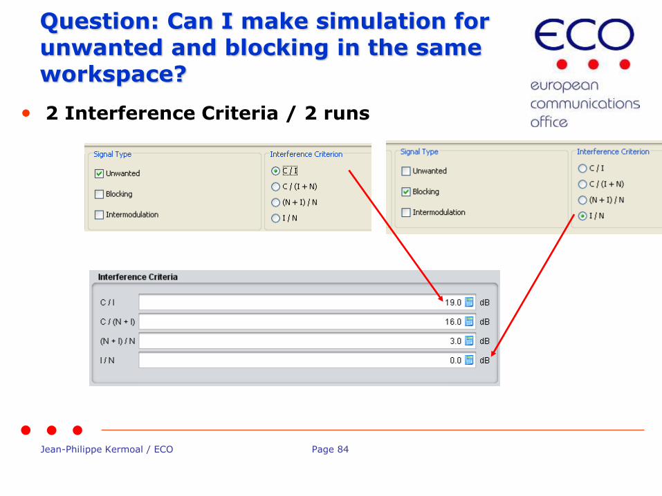
Question: Can I make simulation for unwanted and blocking in the same workspace?
• 2 Interference Criteria / 2 runs
Jean-Philippe Kermoal / ECO Page 85
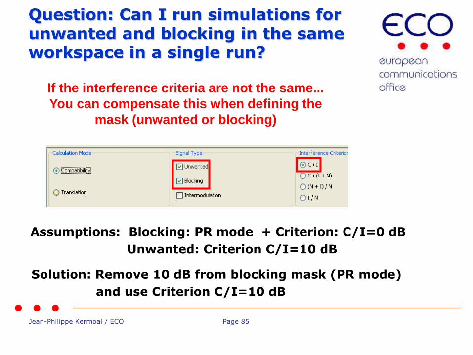
Question: Can I run simulations for unwanted and blocking in the same workspace in a single run?
If the interference criteria are not the same...
You can compensate this when defining the
mask (unwanted or blocking)
Assumptions: Blocking: PR mode + Criterion: C/I=0 dB
Unwanted: Criterion C/I=10 dB
Solution: Remove 10 dB from blocking mask (PR mode)
and use Criterion C/I=10 dB
Jean-Philippe Kermoal / ECO Page 86
Conclusion
• Interference criteria allows:
– To characterise the operation of a system
– To define the technical sharing condition between systems in adjacent or co-channel scenario
• If more that one interference criteria are used, you need to check that they are consistent
• Understand what the tool compute

Jean-Philippe Kermoal / ECO Page 87
Thank you - Any Questions?
Jean-Philippe Kermoal / ECO Page 88
Setting Emission and Blocking masks
European Communications Office
Jean-Philippe Kermoal (ECO)
ISART – May 12, 2015
EUROPEAN COMMUNICATIONS OFFICE
Nansensgade 19 DK-1366 Copenhagen Denmark
Telephone: + 45 33 89 63 00 Telefax: + 45 33 89 63 30
E-mail: [email protected] Web Site: http://www.cept.org/eco

Jean-Philippe Kermoal / ECO Page 89
Outline
Jean-Philippe Kermoal / ECO Page 90
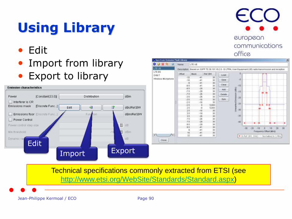
Using Library
• Edit
• Import from library
• Export to library
Edit
Import Export
Technical specifications commonly extracted from ETSI (see
http://www.etsi.org/WebSite/Standards/Standard.aspx)

Jean-Philippe Kermoal / ECO Page 91
Editing the mask
• The emission mask defaults value
• Remove the default using the Clear button.
• Then use the add button to add the enough blank rows for half of the emission mask.
• Note the format of the data:
– Offset = MHz
– Unwanted = dBc
– Reference bandwidth = kHz

Jean-Philippe Kermoal / ECO Page 92
Symmetry
• Then use the Sym button to get a symetric mask

Jean-Philippe Kermoal / ECO Page 93
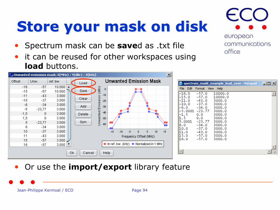
Reference/normalised bandwidth • Once SEAMCAT has generated the whole mask,
first check that the values are in the correct order.
• The unwanted emission diagram shows two masks
The red mask is the representation using the user defined reference bandwidth.
The blue mask is normalised to 1MHz measurement bandwidth. The user may normalise his input to 1MHz bandwidth but it can be useful to input the mask in the bandwidth defined in the standard and allow SEAMCAT to create normalised mask.
Jean-Philippe Kermoal / ECO Page 94
Store your mask on disk • Spectrum mask can be saved as .txt file
• it can be reused for other workspaces using load buttons.
• Or use the import/export library feature
Jean-Philippe Kermoal / ECO Page 95
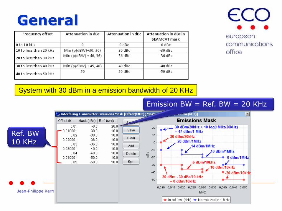
General
Ref. BW 10 KHz
Emission BW = Ref. BW = 20 KHz
System with 30 dBm in a emission bandwidth of 20 KHz
Jean-Philippe Kermoal / ECO Page 96
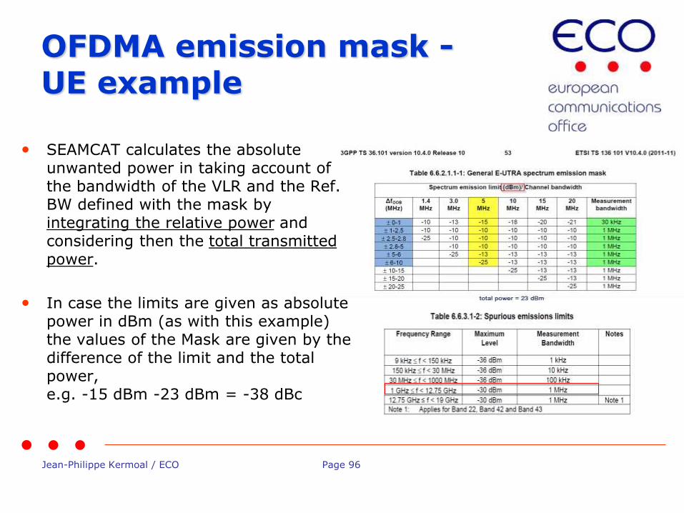
OFDMA emission mask - UE example
• SEAMCAT calculates the absolute unwanted power in taking account of the bandwidth of the VLR and the Ref. BW defined with the mask by integrating the relative power and considering then the total transmitted power.
• In case the limits are given as absolute power in dBm (as with this example) the values of the Mask are given by the difference of the limit and the total power, e.g. -15 dBm -23 dBm = -38 dBc

Jean-Philippe Kermoal / ECO Page 97
Emission Floor
• This emission floor mask (frequency offset (MHz), emission floor (dBm), reference bandwidth (MHz)).
• Useful when power control is used

Jean-Philippe Kermoal / ECO Page 98
ACIR = f(ACLR, ACS)
• ACIR = adjacent-channel interference ratio
• In UL (reverse link), the dominant part of ACIR is due to the UE adjacent channel leakage (ACLR) i.e. ACSBS is very large compare to ACLRUE and ACIR ≈ ACLRUE.
• In DL (forward link), the dominant part of ACIR is due to the UE frequency selectivity (ACS) i.e. ACLRBS is very large compare to ACSUE and ACIR ≈ ACSUE
ACSACLR
ACIR11
1
ACS
1 ACLR
Tx
Rx
Frequency Offset
frequency
Receiver filter
Transmiter mask
No use of the ACLR value directly.
Emission spectrum Mask is used
Jean-Philippe Kermoal / ECO Page 99
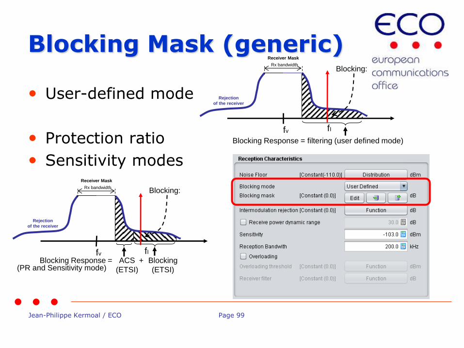
Blocking Mask (generic)
• User-defined mode
• Protection ratio
• Sensitivity modes
fv
Receiver Mask
fI
Rx bandwidth
Rejection
of the receiver
ACS
(ETSI)
Blocking
(ETSI)
+
Blocking:
Blocking Response = (PR and Sensitivity mode)
fv
Receiver Mask
fI
Rx bandwidth
Rejection
of the receiver
Blocking Response = filtering (user defined mode)
Blocking:

Jean-Philippe Kermoal / ECO Page 100
CDMA and OFDMA ACS
• ACS (Adjacent channel selectivity) is the same as the blocking attenuation input
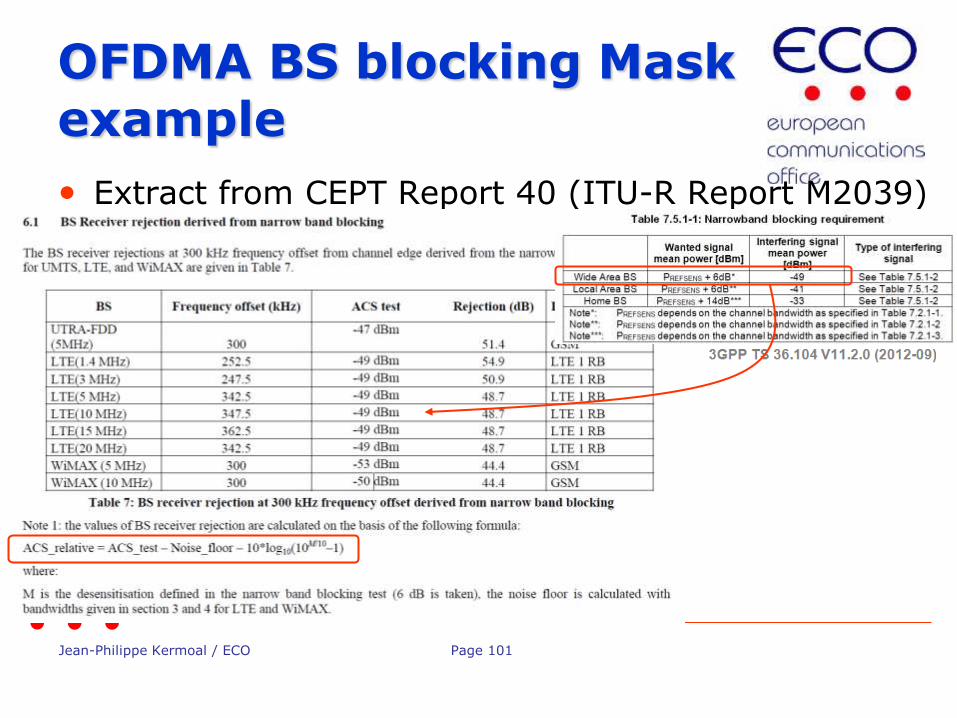
Jean-Philippe Kermoal / ECO Page 101
OFDMA BS blocking Mask example
• Extract from CEPT Report 40 (ITU-R Report M2039)

Jean-Philippe Kermoal / ECO Page 102
Thank you - Any Questions?
Jean-Philippe Kermoal / ECO Page 103
Overview of Systems in SEAMCAT
EUROPEAN COMMUNICATIONS OFFICE
Nansensgade 19 DK-1366 Copenhagen Denmark
Telephone: + 45 33 89 63 00 Telefax: + 45 33 89 63 30
E-mail: [email protected] Web Site: http://www.cept.org/eco
European Communications Office
Jean-Philippe Kermoal (ECO)
ISART – May 12, 2015
Jean-Philippe Kermoal / ECO Page 104
Outline
Jean-Philippe Kermoal / ECO Page 105
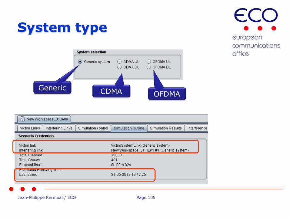
System type
Generic CDMA OFDMA
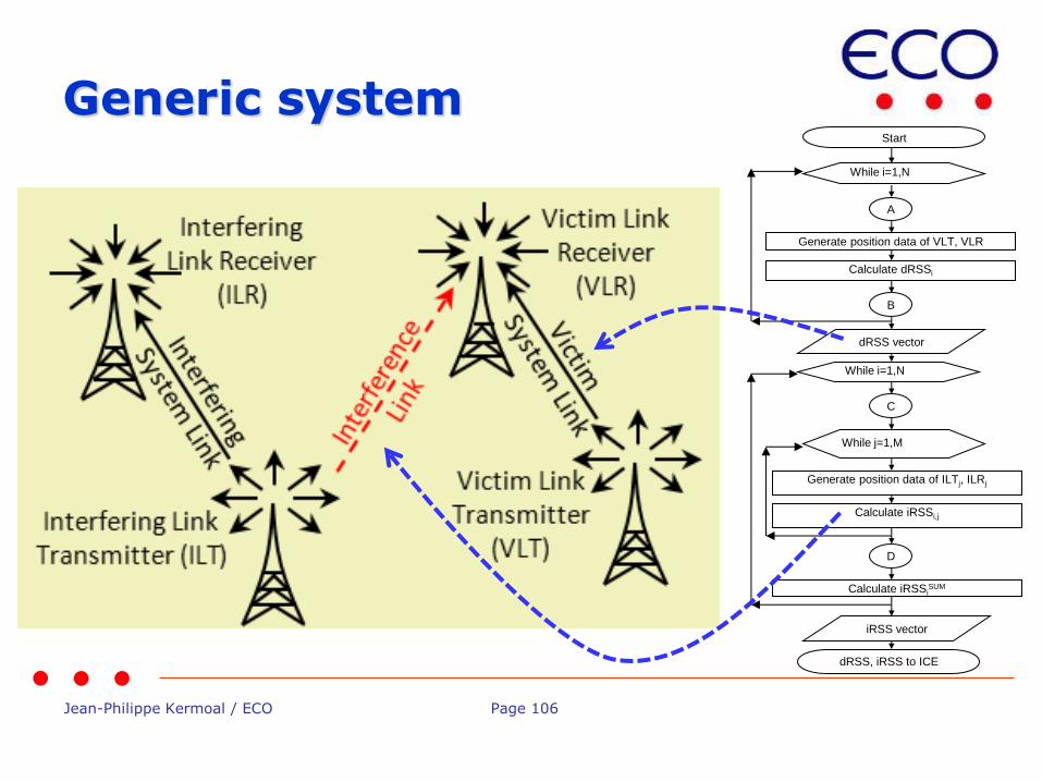
Jean-Philippe Kermoal / ECO Page 106
Generic system Start
While i=1,N
Generate position data of VLT, VLR
Calculate dRSSi
dRSS vector
While i=1,N
Generate position data of ILTj, ILRj
Calculate iRSSi,j
iRSS vector
While j=1,M
Calculate iRSSiSUM
dRSS, iRSS to ICE
A
B
C
D

Jean-Philippe Kermoal / ECO Page 107
Simple and harmonised interface
Add
Duplicate Delete
Multiple interferer generation
On-line Help
Workspaces Interfering links

Jean-Philippe Kermoal / ECO Page 108
Cellular modelling
• Modelling of cellular systems as victim, interferer, or both: • Quasi-static time within a snapshot
• One direction at a time (uplink or downlink)
• CDMA • Voice traffic only
• Particular CDMA standard defined by setting Link Level Data (CDMA2000-1X, W-CDMA/UMTS)
• OFDMA • LTE
Jean-Philippe Kermoal / ECO Page 109
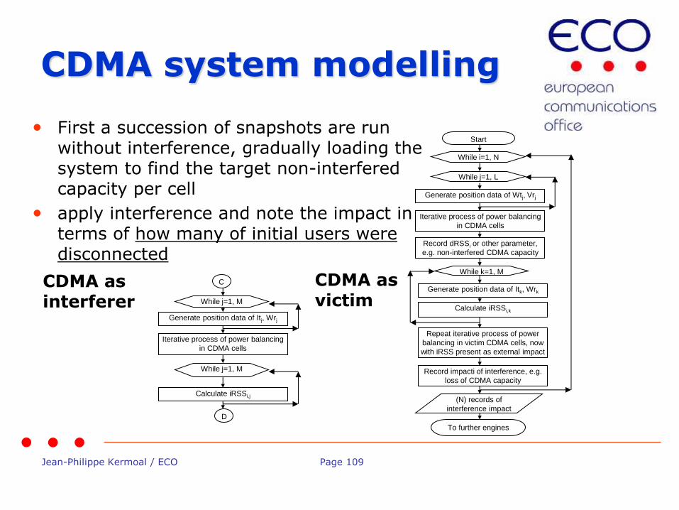
• First a succession of snapshots are run without interference, gradually loading the system to find the target non-interfered capacity per cell
• apply interference and note the impact in terms of how many of initial users were disconnected
Generate position data of Wtj, Vrj
While j=1, L
Iterative process of power balancing
in CDMA cells
Record dRSSi or other parameter,
e.g. non-interfered CDMA capacity
Start
While i=1, N
Generate position data of Itk, Wrk
Calculate iRSSi,k
While k=1, M
Repeat iterative process of power
balancing in victim CDMA cells, now
with iRSS present as external impact
(N) records of
interference impact
Record impacti of interference, e.g.
loss of CDMA capacity
To further engines
CDMA as victim
Generate position data of Itj, Wrj
C
D
While j=1, M
Iterative process of power balancing
in CDMA cells
Calculate iRSSi,j
While j=1, M
CDMA as interferer
CDMA system modelling
Jean-Philippe Kermoal / ECO Page 110
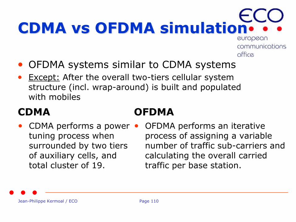
CDMA vs OFDMA simulation
CDMA
• CDMA performs a power tuning process when surrounded by two tiers of auxiliary cells, and total cluster of 19.
OFDMA
• OFDMA performs an iterative process of assigning a variable number of traffic sub-carriers and calculating the overall carried traffic per base station.
• OFDMA systems similar to CDMA systems
• Except: After the overall two-tiers cellular system structure (incl. wrap-around) is built and populated with mobiles
Jean-Philippe Kermoal / ECO Page 111
Conclusions
• Harmonised interface between generic and CDMA/OFDMA modules
• Versatile tool to configure victim and interferer

Jean-Philippe Kermoal / ECO Page 112
Thank you - Any questions?
Jean-Philippe Kermoal / ECO Page 113
Propagation model: Built-in and plug-in
EUROPEAN COMMUNICATIONS OFFICE
Nansensgade 19 DK-1366 Copenhagen Denmark
Telephone: + 45 33 89 63 00 Telefax: + 45 33 89 63 30
E-mail: [email protected] Web Site: http://www.cept.org/eco
European Communications Office
Jean-Philippe Kermoal (ECO)
ISART – May 12, 2015
Jean-Philippe Kermoal / ECO Page 114
Outline
Jean-Philippe Kermoal / ECO Page 115
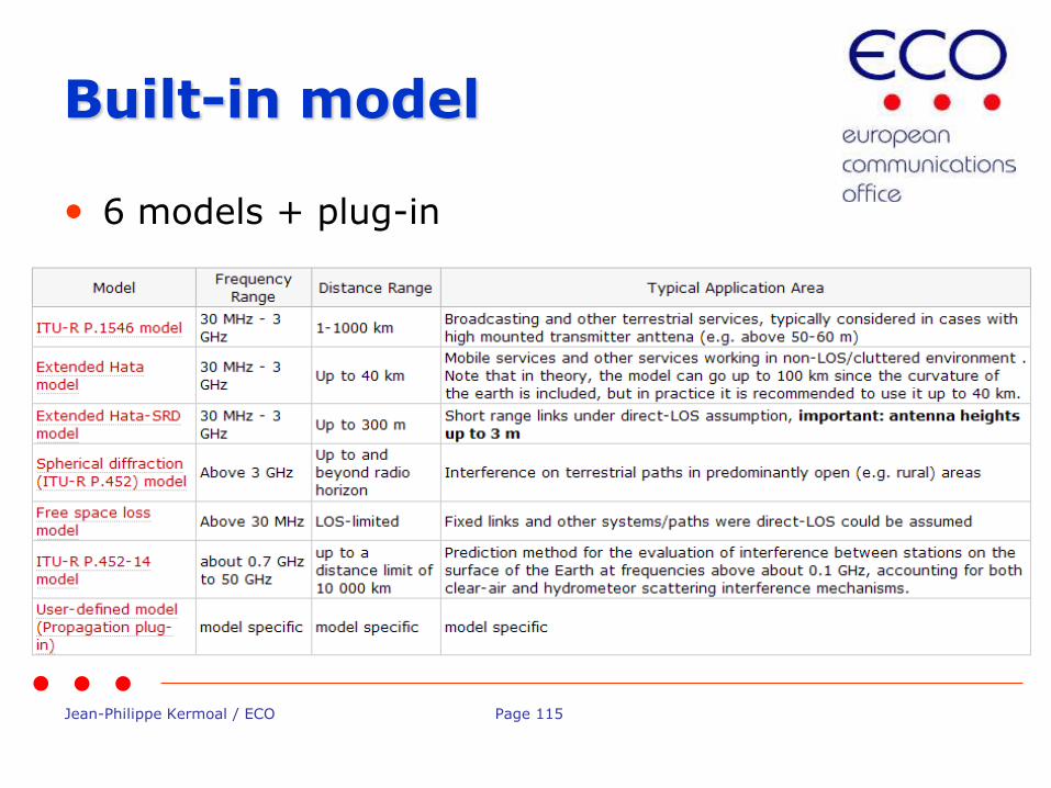
Built-in model
• 6 models + plug-in
Jean-Philippe Kermoal / ECO Page 116
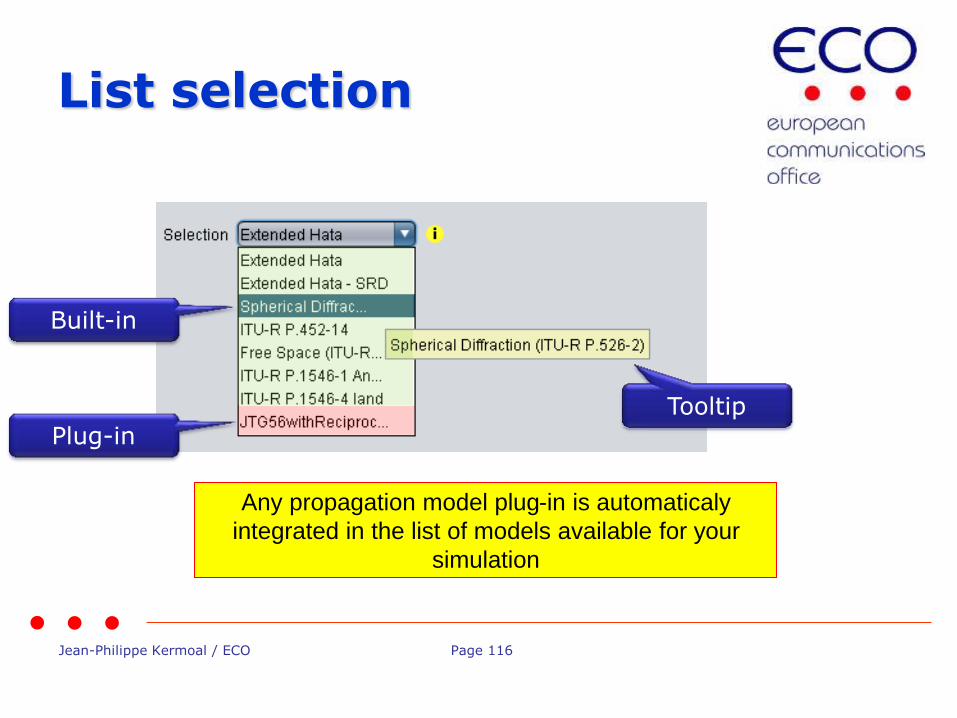
List selection
Tooltip
Built-in
Plug-in
Any propagation model plug-in is automaticaly
integrated in the list of models available for your
simulation
Jean-Philippe Kermoal / ECO Page 117
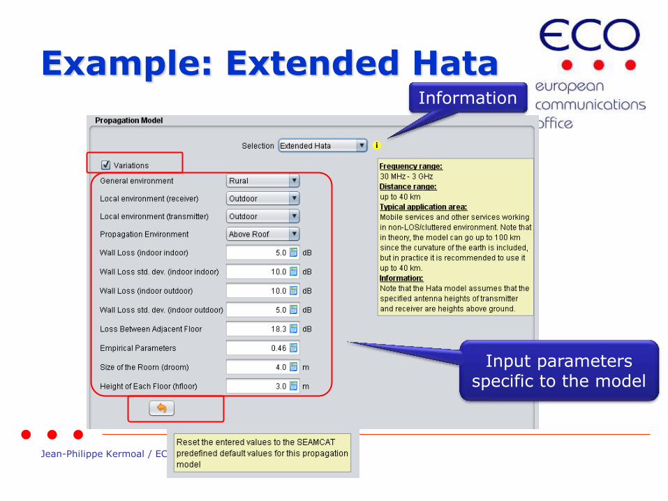
Example: Extended Hata Information
Input parameters specific to the model
Jean-Philippe Kermoal / ECO Page 118
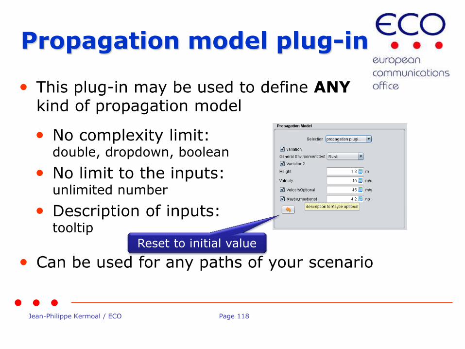
• This plug-in may be used to define ANY kind of propagation model
• Can be used for any paths of your scenario
Propagation model plug-in
• No complexity limit: double, dropdown, boolean
• No limit to the inputs: unlimited number
• Description of inputs: tooltip
Reset to initial value

Jean-Philippe Kermoal / ECO Page 119
Plug-in
• 2 choices
– .class file
– .jar file (recommended) to allow embedement of the plugin in the workspace to allow easier dissemination of your workspace
Jean-Philippe Kermoal / ECO Page 120
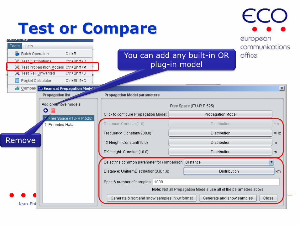
Test or Compare
You can add any built-in OR plug-in model
Remove

Jean-Philippe Kermoal / ECO Page 121
Example #10: Free Space
fd
hhL
rxtx log201000
log105.32 2
2
• L = 32.5+10log(8)+20log(1000))
• L = 101.5 dB
Jean-Philippe Kermoal / ECO Page 122
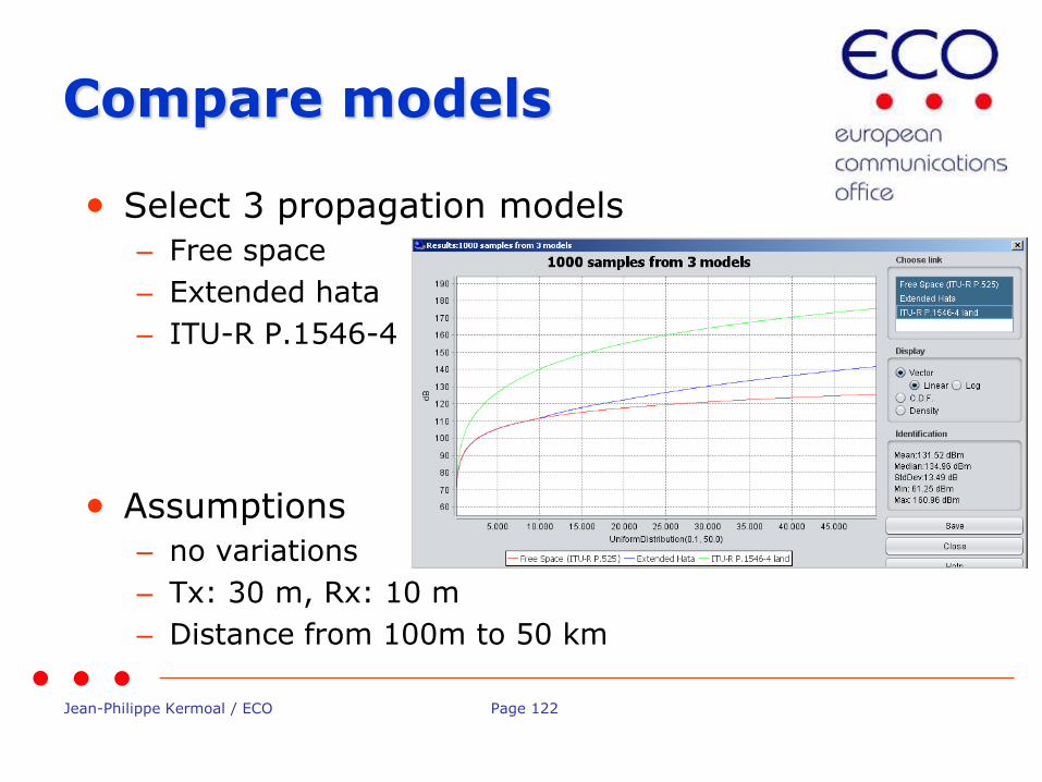
Compare models
• Select 3 propagation models
– Free space
– Extended hata
– ITU-R P.1546-4
• Assumptions
– no variations
– Tx: 30 m, Rx: 10 m
– Distance from 100m to 50 km

Jean-Philippe Kermoal / ECO Page 123
Thank you - Any Questions?
Jean-Philippe Kermoal / ECO Page 124
SEAMCAT Version 5.0.0
EUROPEAN COMMUNICATIONS OFFICE
Nansensgade 19 DK-1366 Copenhagen Denmark
Telephone: + 45 33 89 63 00 Telefax: + 45 33 89 63 30
E-mail: [email protected] Web Site: http://www.cept.org/eco
European Communications Office
Jean-Philippe Kermoal (ECO)
ISART – May 12, 2015
Jean-Philippe Kermoal / ECO Page 125
Version 5.0.0
• The official version is 4.0.1
• New version 5.0.0 expected to be available in September 2015
• Currently in alpha testing phase

Jean-Philippe Kermoal / ECO Page 126
What’s new in 5.0.0
• Calculation unchanged (except bug fix)
• New .jar distribution
• System approach GUI
• Advanced plugins for antenna
• Introduction of EPP – Event Processing Plugins
• Parallel processing on multi-core machine
Jean-Philippe Kermoal / ECO Page 127
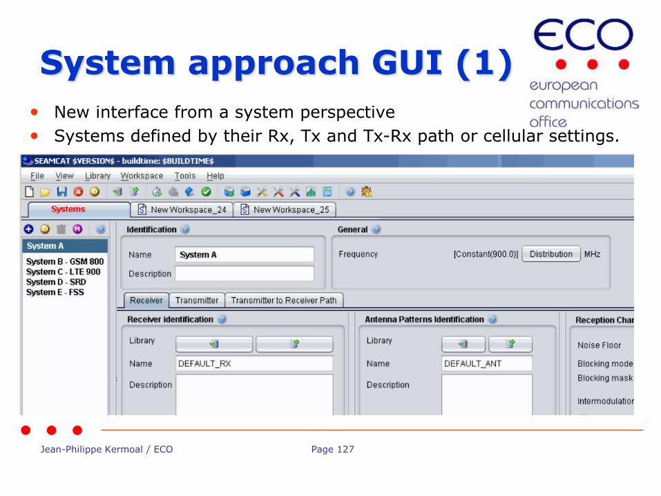
System approach GUI (1)
• New interface from a system perspective
• Systems defined by their Rx, Tx and Tx-Rx path or cellular settings.

Jean-Philippe Kermoal / ECO Page 128
System approach GUI (2)
• The user will select whatever system for the victim and the interfering links.
Jean-Philippe Kermoal / ECO Page 129
Antenna plugins
• Antenna will be implemented in plugin
• Allow to introduce frequency etc.. into the antenna pattern computation
• Allows any implementation of ITU.R recommendation (e.g. ITU-R Rec. F.1336, ITU-R Rec. F.699 and ITU-R Rec. F. 1245 etc...)
Jean-Philippe Kermoal / ECO Page 130
Event Processing Plugins
• Black box disappear
• EPPs can extract intermediary results
• EPPs can further extend algorithm
• easy EPP plugins integration to the workspace

Jean-Philippe Kermoal / ECO Page 131
Thank you - Any questions?
Jean-Philippe Kermoal / ECO Page 132
US questions related to SEAMCAT
European Communications Office
Jean-Philippe Kermoal - SEAMCAT Manager (ECO)
ISART – May 12, 2015
EUROPEAN COMMUNICATIONS OFFICE
Nansensgade 19 DK-1366 Copenhagen Denmark
Telephone: + 45 33 89 63 00 Telefax: + 45 33 89 63 30
E-mail: [email protected] Web Site: http://www.cept.org/eco
Jean-Philippe Kermoal / ECO Page 133
Outline

Jean-Philippe Kermoal / ECO Page 134
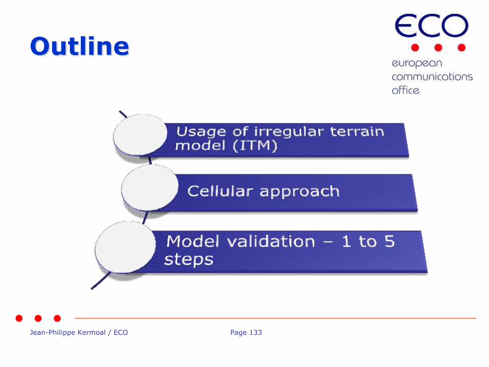
Usage of irregular terrain model (ITM) • Need to understand the European regulatory approach (Ex-Ante vs Ex-
post)
– Ex-Ante, European regulation (ECC) is based on compatibility studies that defines technical conditions
– Later, comes the Harmonised Standard (ETSI) which establish the conformity requirement based on the ECPT work for the introduction of the equipment on the European Market (EU)
– Ex-post is more of a national matter to ensure that there is no interference -> monitoring/market surveillance.
Therefore from an Ex-Ante perspective, the CEPT is more interested in generic study and the usage of terrain model for monte carlo simulation is questionable.

Jean-Philippe Kermoal / ECO Page 135
What about SEAMCAT? • Studies in SEAMCAT are generic
• Assume flat terrain surface in version 4.1.0
• This is not a planning or a coordination tool
• Next generation of SEAMCAT (version 5.0.0)
– Introduction of the Event Processing Plugin (EPP)
– Allows terrain mapping
– This is at the user responsibility to generate results
(source: STG(14)44 terrain profile draft)
Jean-Philippe Kermoal / ECO Page 136
Cellular approach
• LTE power control based on the 3GPP TR36.942
• Very generic model – result of a compromise at 3GPP when establishing LTE simulation between industry players
• Reality is particular to vendors product
• See presentation on the CDMA/OFDMA overview for details
Jean-Philippe Kermoal / ECO Page 137
Model validation 1 to 5 steps
1. Is my model close to reality?
– Propagation model
Most of CEPT studies are based on model from the ITU-R P. Recommendation. So the ”validity” has been discussed at the ITU by propagation experts.
Occasionaly other models are considered, then it is during the Project Team activity that agreement are reached to use one model or another. Project Team members consist of ALL stackeholders (Administrations, Industry) to ensure a balance in all the views.
– LTE algorithm
The 3GPP TR36.942 was generated with all the major mobile vendors and operators involved. They compared there various simulators and after convergence in their results provided some benchmarking results that was used to tune SEAMCAT.

Jean-Philippe Kermoal / ECO Page 138
Model validation 1 to 5 steps
2. Is the implementation of model according to the specification?
– Extensive testing based on specification received
– Extensive usage in CEPT (easier to detect bugs)
3. How do we ensure that SEAMCAT ver(n+1) is in line with previous SEAMCAT ver(n)?
– ~100.000 Lines of code
– Automated benchmarking system has been established based on Junit test. (fixing seeds )
– Propagation models have specific test module
– Before any release an integration test is perfomed on more than 450 different workspaces
4. Open community – we promote feedback from users
5. Version 5.0.0 giving access to intermediary results
Jean-Philippe Kermoal / ECO Page 139
Thank you - Any questions?