Embed Size (px)
Citation preview

Khalifa, A., L. De Lorenzis, and A. Nanni, "FRP Composites for Shear Strengtheneing of RC Beams,” Proc., 3rd Inter. Conf. on Advanced Composite Materials in Bridges and Structures, Ottawa,Canada, J. Humar and A.G. Razaqpur, Editors, 15-18 Aug. 2000, pp. 137-144.
1
FRP COMPOSITES FOR SHEAR STRENGTHENING OF RC BEAMS
Ahmed Khalifa Laura De Lorenzis Antonio Nanni Structural Eng. Dept., Innovation Eng. Dept. Civil Eng. Dept. University of Alexandria University of Lecce University of Missouri-Rolla Alexandria, 21544 Lecce, 73100 Rolla, MO, 65409 Egypt Italy USA Abstract
ABSTRACT
Fiber Reinforced Polymer (FRP) composite systems can be used for shear strengthening of reinforced concrete (RC) members. The present study investigated the shear performance and the modes of failure of simply supported RC T-beams externally strengthened in shear with FRP composites. Two different FRP-based strengthening systems were investigated, namely, externally bonded FRP sheets and Near Surface Mounted (NSM) FRP rods. The latter is a novel technique on which no literature is available to date. The experimental program consisted of testing eleven full-scale, T beams. The beams were grouped into three series. The first series was tested to investigate the influence on the shear capacity of the concrete surface roughness and of the carbon FRP sheets axial rigidity. The second series focused on the capability of externally bonded CFRP reinforcement to enhance the ultimate capacity of beams that already have adequate internal steel reinforcement. In addition, a beam with
internal glass FRP stirrups was tested in this series. In the third series, the novel shear strengthening system of NSM CFRP rods was evaluated.
The test results confirm that externally bonded CFRP sheets and NSM CFRP rods can be used to increase significantly the shear capacity, with efficiency that varies depending on the tested variables. The test results were used to validate a previously proposed shear design approach.
Khalifa, A., L. De Lorenzis, and A. Nanni, "FRP Composites for Shear Strengtheneing of RC Beams,” Proc., 3rd Inter. Conf. on Advanced Composite Materials in Bridges and Structures, Ottawa,Canada, J. Humar and A.G. Razaqpur, Editors, 15-18 Aug. 2000, pp. 137-144.
2
INTRODUCTION
Externally bonded carbon fiber reinforced polymer (CFRP) sheets continue to show great promise for use in shear strengthening of existing reinforced concrete (RC) beams (Taerwe et al. 1997). Some of the parameters that may affect the shear capacity of the strengthened beams such as concrete surface roughness prior to CFRP application, and CFRP sheets axial rigidity are investigated in this study. Furthermore, an alternative strengthening system is described and evaluated. This system will be referred to as near-surface mounted (NSM) FRP rods.
NEAR-SURFACE MOUNTED FRP RODS NSM FRP rods are emerging as an alternative to externally bonded FRP laminates for external strengthening of RC structures. Embedment of the rods is achieved by grooving the surface of the member along the desired direction. The groove is filled half way with epoxy paste, the FRP rod is then placed in the groove and lightly pressed, so forcing the paste to flow around the rod and fill completely between the rod and the sides of the groove. The groove is then filled with more paste and the surface is leveled. Details of the final product are illustrated in the sketch of Fig. 1.
Epoxy Paste
FRP Rod
Groove
Fig. 1. NSM rods detail NSM FRP rods can be used for shear strengthening of RC beams. This technique involves cutting vertical or inclined grooves on the side surfaces of the beam, as shown in Fig. 2., and embedding the FRP rods in the epoxy-filled grooves. The advantage of NSM rods with respect to FRP laminates in this application is that no surface preparation other than grooving is required.
EXPERIMENTAL PROGRAM
Test Specimens and Materials The experimental program in this study consisted of testing seven full-scale beams with a T-shaped cross-section. The specimens were divided into two groups designated as A and B.

Khalifa, A., L. De Lorenzis, and A. Nanni, "FRP Composites for Shear Strengtheneing of RCBeams,” Proc., 3rd Inter. Conf. on Advanced Composite Materials in Bridges and Structures,Ottawa,Canada, J. Humar and A.G. Razaqpur, Editors, 15-18 Aug. 2000, pp. 137-144.
3
Group A focused on the influence of concrete surface roughness and CFRP sheets axial rigidity on the shear capacity of the strengthened beams. In Group B, NSM CFRP rods were evaluated. The details and dimensions of the specimens are illustrated in Fig. 3. The mechanical properties of the materials used for manufacturing the test specimens are listed in Table 1.
Fig. 2. Beam with vertical grooves prior to shear strengthening with NSM FRP rods
Dimensions in mm Fig. 3. Beam specimen detailing and dimensions
355 355No stirrups 3050
405
380
100
305
150
2 D 13
2 D 28
Stirrups D=10
Khalifa, A., L. De Lorenzis, and A. Nanni, "FRP Composites for Shear Strengtheneing of RC Beams,” Proc., 3rd Inter. Conf. on Advanced Composite Materials in Bridges and Structures,Ottawa,Canada, J. Humar and A.G. Razaqpur, Editors, 15-18 Aug. 2000, pp. 137-144.
4
Strengthening Configuration
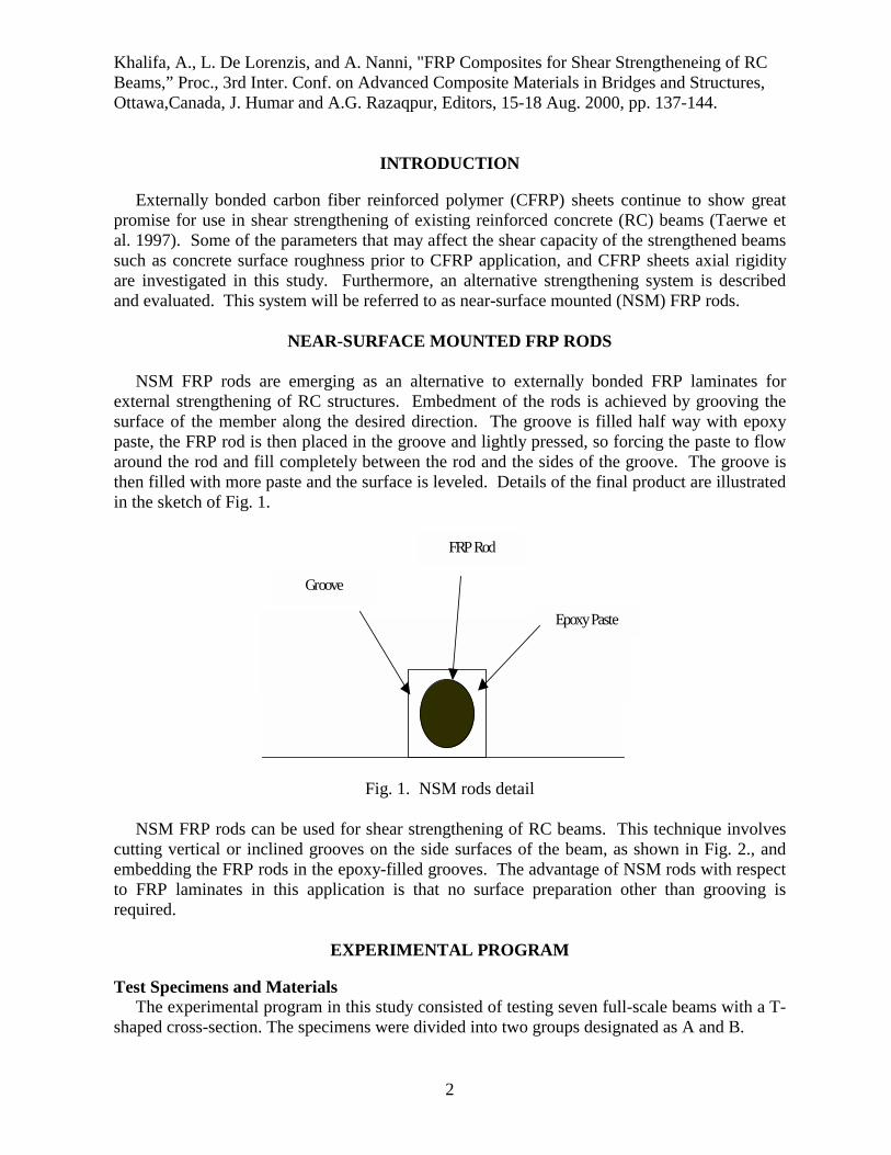
Strengthening with Externally Bonded CFRP Sheets (Group A): In this test group, five beam specimens were tested. Specimen A1 was left without strengthening and tested as control specimen. In Specimen A2, the concrete surfaces were prepared prior to CFRP application by regular water blasting and strengthened with one ply continuous U-warp of high tensile CFRP sheets (CF-130) with the fiber direction oriented perpendicular to the longitudinal axis of the specimen. The CFRP wraps were applied following the manufacturer’s recommendations (MBrace 1998).
Table 1 – Material properties
Material Dimensions
(mm)
Yield point (MPa)
Compressive strength (MPa)
Ultimate tensile
strength (MPa)
Modulus of
elasticity (GPa)
Concrete ---- ---- 32 ---- 28 D = 28 430 ---- 730 200 D = 13 350 ---- 530 200
Steel bars Steel bars Steel bars D = 10 350 ---- 530 200 CFRP rods D = 10 ---- ---- 1900 105 CFRP sheets* (CF-530) tf = 0.165 ---- ---- 3520 372 CFRP sheets* (CF-130) tf = 0.165 ---- ---- 3790 228 * Fiber only In Specimen A3, the concrete surface roughness degree was higher than in Specimen A2. A heavy water blasting was used to create a rougher surface as compared to that of Specimen A2. Thereafter, the specimen was strengthened similarly to Specimen A2. In Specimen A4, small holes throughout the shear spans were made to increase the surface roughness as shown in Fig. 4. The holes were made using a hammer drill with spacing between holes of about 25 mm. The hole diameter was 10 mm. And the depth was 4 mm. Then, the concrete surfaces were treated with regular water blasting and the beam was strengthened similarly to Specimen A2.

Khalifa, A., L. De Lorenzis, and A. Nanni, "FRP Composites for Shear Strengtheneing of RC Beams,” Proc., 3rd Inter. Conf. on Advanced Composite Materials in Bridges and Structures,Ottawa,Canada, J. Humar and A.G. Razaqpur, Editors, 15-18 Aug. 2000, pp. 137-144.
5
Fig. 4. Specimen A4 prepared with regular water blasting and holes
In Specimen A5, the concrete surfaces were prepared with regular water blasting and then strengthened with one-ply high modulus (CF-530) continuous U-warp. The specimen was tested to investigate the influence of CFRP axial rigidity on its contribution to the shear capacity. Strengthening with NSM CFRP Rods (Group B): In Group B, two specimens strengthened with NSM CFRP rods were tested to investigate their performance and modes of failure. These two specimens were externally strengthened with vertical NSM rods at a spacing of 175 mm. (Specimen B1) and 125 mm. (Specimen B2). Commercially available CFRP deformed rods were used. The rods were embedded in the grooves using a commercially available epoxy-based paste (De Lorenzis 2000). The epoxy was allowed to cure for 15 days (full cure time at room temperature) prior to testing of the beams.
Test Setup and Instrumentation All specimens were tested as simply supported beams using a four-point loading scheme with shear span-to-depth ratio of 3. A hydraulic jack of 1000 kN capacity was used to apply the load on a steel distribution beam which generated the two concentrated loads (Fig. 5). A load cell was placed below the hydraulic jack to measure the vertical force applied.

Khalifa, A., L. De Lorenzis, and A. Nanni, "FRP Composites for Shear Strengtheneing of RC Beams,” Proc., 3rd Inter. Conf. on Advanced Composite Materials in Bridges and Structures,Ottawa,Canada, J. Humar and A.G. Razaqpur, Editors, 15-18 Aug. 2000, pp. 137-144.
6
Fig. 5. Test setup of Specimen A3
Four linear variable differential transformers (LVDTs) were used for each test. Two LVDTs monitored the mid-span displacement at the two sides of the beam, the other two were used to measure the settlement of the supports. For each specimen strengthened with CFRP sheets, ten strain gauges were attached directly to the FRP sheets on the sides of the beam and oriented in the vertical direction to monitor FRP strain. The strain gauges were mounted at the locations of expected shear cracks (as observed in reference specimen A1 during testing). In Specimens B1 and B2, the strain gages were placed on the FRP rods at various locations, to monitor the strain distribution on the rods during the test(De Lorenzis, 2000). Test Results and Discussions Group A: The results in terms of total applied load versus net mid span deflection are shown in Fig. 6. During loading of Specimen A1, diagonal shear cracks formed at a load of 115 kN. The shear cracks initiated at the center of both shear spans simultaneously. The first shear crack was the critical crack in the specimen. As the load increased, this crack started to widen and propagated leading to failure at a load of 177 kN.
In Specimen A2, the failure was brittle and occurred at a total load of 308 kN due to debonding of the CFRP sheet (with a thin layer of concrete adhered to it) over the main shear crack at the same location observed in Specimen A1. It was followed directly by shear compression failure. Strengthening of Specimen A2 resulted in a 74% increase in the shear capacity as compared to Specimen A1. The maximum localized CFRP vertical strain measured at failure was 0.0045 mm/mm, which corresponding to 28% of the reported ultimate CFRP strain. This value is not an absolute maximum because it greatly depends on the location of the strain gauges with respect to the cracks. In Specimen A3, the failure was initiated by debonding of the CFRP, with more concrete attached to the delaminated ply as compared to Specimen A2. It was followed by shear compression failure at a total load of 323 kN. The maximum-recorded CFRP vertical strain at failure was 0.004 mm/mm, corresponding to 24% of the ultimate CFRP strain. No significant
Khalifa, A., L. De Lorenzis, and A. Nanni, "FRP Composites for Shear Strengtheneing of RCBeams,” Proc., 3rd Inter. Conf. on Advanced Composite Materials in Bridges and Structures, Ottawa,Canada, J. Humar and A.G. Razaqpur, Editors, 15-18 Aug. 2000, pp. 137-144.
7
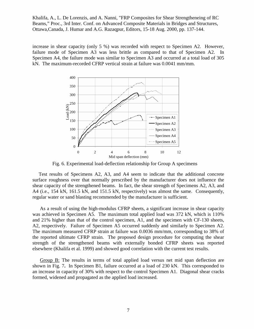
increase in shear capacity (only 5 %) was recorded with respect to Specimen A2. However, failure mode of Specimen A3 was less brittle as compared to that of Specimen A2. In Specimen A4, the failure mode was similar to Specimen A3 and occurred at a total load of 305 kN. The maximum-recorded CFRP vertical strain at failure was 0.0041 mm/mm.
0
50
100
150
200
250
300
350
400
0 2 4 6 8 10 12Mid span deflection (mm)
Load
(kN
)
Specimen A1Specimen A2Specimen A3Specimen A4Specimen A5
Fig. 6. Experimental load-deflection relationship for Group A specimens
Test results of Specimens A2, A3, and A4 seem to indicate that the additional concrete surface roughness over that normally prescribed by the manufacturer does not influence the shear capacity of the strengthened beams. In fact, the shear strength of Specimens A2, A3, and A4 (i.e., 154 kN, 161.5 kN, and 151.5 kN, respectively) was almost the same. Consequently, regular water or sand blasting recommended by the manufacturer is sufficient. As a result of using the high-modulus CFRP sheets, a significant increase in shear capacity was achieved in Specimen A5. The maximum total applied load was 372 kN, which is 110% and 21% higher than that of the control specimen, A1, and the specimen with CF-130 sheets, A2, respectively. Failure of Specimen A5 occurred suddenly and similarly to Specimen A2. The maximum measured CFRP strain at failure was 0.0036 mm/mm, corresponding to 38% of the reported ultimate CFRP strain. The proposed design procedure for computing the shear strength of the strengthened beams with externally bonded CFRP sheets was reported elsewhere (Khalifa et al. 1999) and showed good correlation with the current test results. Group B: The results in terms of total applied load versus net mid span deflection are shown in Fig. 7. In Specimen B1, failure occurred at a load of 230 kN. This corresponded to an increase in capacity of 30% with respect to the control Specimen A1. Diagonal shear cracks formed, widened and propagated as the applied load increased.

Khalifa, A., L. De Lorenzis, and A. Nanni, "FRP Composites for Shear Strengtheneing of RC Beams,” Proc., 3rd Inter. Conf. on Advanced Composite Materials in Bridges and Structures,Ottawa,Canada, J. Humar and A.G. Razaqpur, Editors, 15-18 Aug. 2000, pp. 137-144.
8
0
50
100
150
200
250
300
350
400
0 2 4 6 8 10 12
Midspan deflection (mm)
Load
(kN
)
Specimen A1Specimen B1Specimen B2
Fig. 7 Experimental load-deflection relationship for Group B specimen
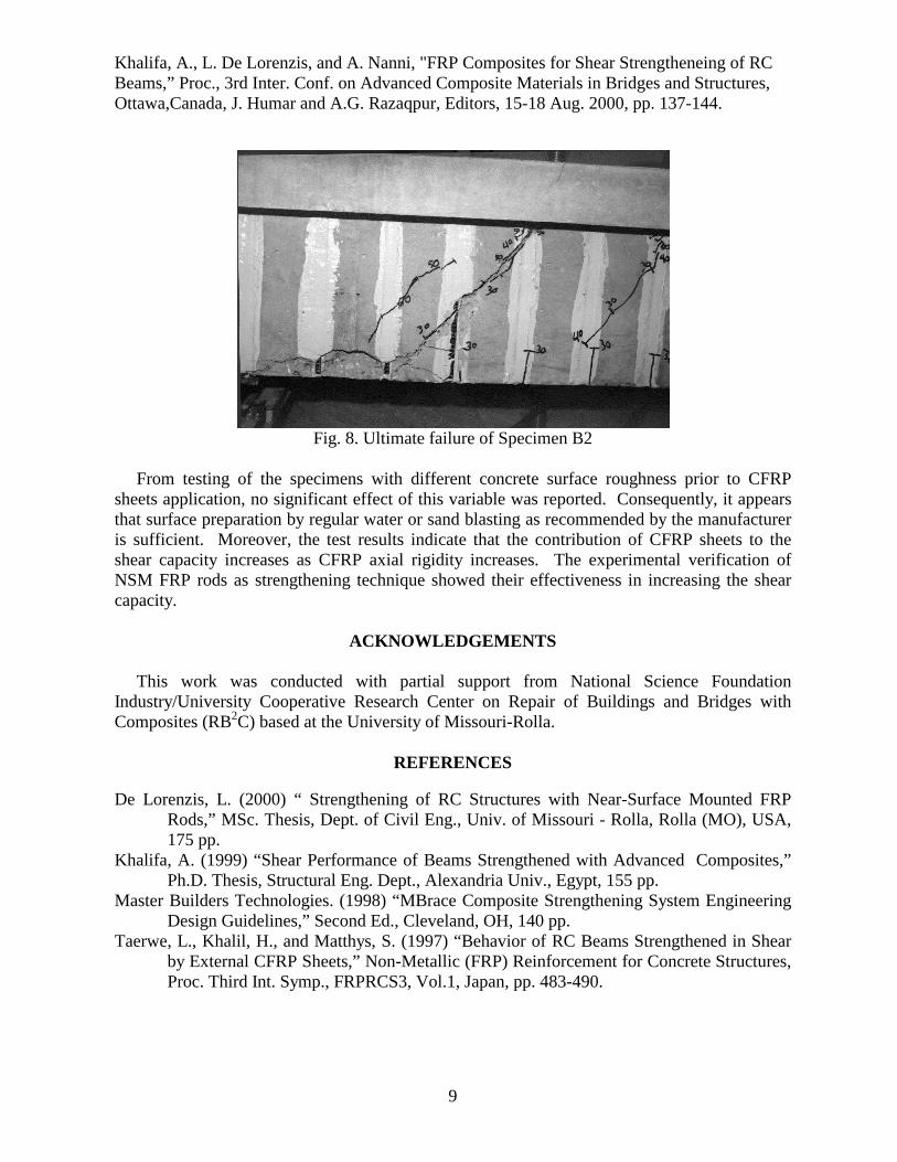
A crackling noise revealed throughout the test the progressive cracking of the epoxy paste in which the CFRP rods were embedded. Failure eventually occurred by splitting of the epoxy cover in one of the NSM FRP rods intersected by the major shear crack. The same behavior was observed and the same failure mode resulted in Specimen B2 (Fig. 8), which differed from B1 only for the closer spacing of the rods (125 mm).
The ultimate load was 255 kN, corresponding to an increase in capacity of 44% over the control specimen and of 11% over specimen B1. The proposed design procedure for computing the shear contribution of NSM FRP rods is reported elsewhere (De Lorenzis, 2000).
CONCLUSIONS
An experimental study on shear performance and modes of failure of simply supported RC T-beams strengthened with externally bonded FRP composites was presented. Two different FRP-based strengthening systems were investigated, namely, externally bonded CFRP sheets and NSM FRP rods.
Khalifa, A., L. De Lorenzis, and A. Nanni, "FRP Composites for Shear Strengtheneing of RC Beams,” Proc., 3rd Inter. Conf. on Advanced Composite Materials in Bridges and Structures,Ottawa,Canada, J. Humar and A.G. Razaqpur, Editors, 15-18 Aug. 2000, pp. 137-144.
9
Fig. 8. Ultimate failure of Specimen B2
From testing of the specimens with different concrete surface roughness prior to CFRP sheets application, no significant effect of this variable was reported. Consequently, it appears that surface preparation by regular water or sand blasting as recommended by the manufacturer is sufficient. Moreover, the test results indicate that the contribution of CFRP sheets to the shear capacity increases as CFRP axial rigidity increases. The experimental verification of NSM FRP rods as strengthening technique showed their effectiveness in increasing the shear capacity.
ACKNOWLEDGEMENTS
This work was conducted with partial support from National Science Foundation Industry/University Cooperative Research Center on Repair of Buildings and Bridges with Composites (RB2C) based at the University of Missouri-Rolla.
REFERENCES
De Lorenzis, L. (2000) “ Strengthening of RC Structures with Near-Surface Mounted FRP
Rods,” MSc. Thesis, Dept. of Civil Eng., Univ. of Missouri - Rolla, Rolla (MO), USA, 175 pp.
Khalifa, A. (1999) “Shear Performance of Beams Strengthened with Advanced Composites,” Ph.D. Thesis, Structural Eng. Dept., Alexandria Univ., Egypt, 155 pp.
Master Builders Technologies. (1998) “MBrace Composite Strengthening System Engineering Design Guidelines,” Second Ed., Cleveland, OH, 140 pp.
Taerwe, L., Khalil, H., and Matthys, S. (1997) “Behavior of RC Beams Strengthened in Shear by External CFRP Sheets,” Non-Metallic (FRP) Reinforcement for Concrete Structures, Proc. Third Int. Symp., FRPRCS3, Vol.1, Japan, pp. 483-490.