Embed Size (px)
Citation preview
2009 SIMULIA Customer Conference 1
Advanced Finite Element Analysis for the Skyhook-Boeing HLV Aircraft
Frank A. Smith Jr.
The Boeing Company
Abstract: Boeing and Skyhook International entered into an agreement whereby Boeing will design and build two prototypes of the new Skyhook HLV aircraft. This hybrid airship is intended to carry 40 tons of cargo 100 miles. Due to the flexible, non-linear nature of fabric airship envelopes, as well as the complexity of designing a hybrid airship, the internal loads model for this aircraft is being developed in Abaqus and will be solved non-linearly. Additionally, certain key technologies within Abaqus are being used in the early stages of aircraft development to help speed up the design process and improve accuracy. Keywords: Aircraft, airship, conceptual design, loads modeling, non-linear loads modeling, internal loads modeling.
1. Introduction
In 2007 Boeing was approached by Skyhook International to assess the concept feasibility of a 40- ton VTOL capable platform. Subsequent to the feasibility study The Boeing Company entered into an agreement to begin development of the first-of-its-kind SkyHook aircraft, which operates on neutral buoyancy principles that will revolutionize VTOL (Vertical Take Off and Landing) by using a combination of aerostatic lift and rotorcraft technologies to transport loads of up to 40 tons for up to 200 miles without refueling.
Target markets for the new aircraft include the oil and gas industry, mining industry, civil construction, and the general transport of heavy loads in remote regions of the world where conventional transportation does not exist or where building such infrastructure is difficult, costly or environmentally unfavorable. Boeing is designing and will fabricate two production SkyHook prototypes at its Rotorcraft Systems facility in Ridley Park, Pa. In November 2008, Boeing completed the “configuration freeze” phase, a major milestone, which fixes the overall performance and layout of the aircraft, including the operational range, structural and systems design, analysis and certification approach. The project team is currently in the “critical systems selection” phase, where existing equipment, components and systems are matched to the aircraft requirements.
The new aircraft will enter commercial service as soon as it is certified by Transport Canada and the U.S. Federal Aviation Administration. The first SkyHook aircraft is scheduled to fly in 2012.
2 2009 SIMULIA Customer Conference
2. Non-Linear Internal Loads Modeling
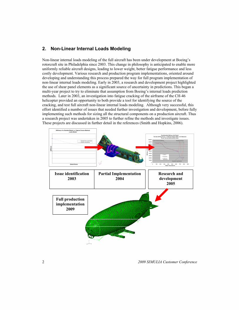
Non-linear internal loads modeling of the full aircraft has been under development at Boeing’s rotorcraft site in Philadelphia since 2003. This change in philosophy is anticipated to enable more uniformly reliable aircraft designs, leading to lower weight, better fatigue performance and less costly development. Various research and production program implementations, oriented around developing and understanding this process prepared the way for full program implementation of non-linear internal loads modeling. Early in 2003, a research and development project highlighted the use of shear panel elements as a significant source of uncertainty in predictions. This began a multi-year project to try to eliminate that assumption from Boeing’s internal loads prediction methods. Later in 2003, an investigation into fatigue cracking of the airframe of the CH-46 helicopter provided an opportunity to both provide a tool for identifying the source of the cracking, and test full aircraft non-linear internal loads modeling. Although very successful, this effort identified a number of issues that needed further investigation and development, before fully implementing such methods for sizing all the structural components on a production aircraft. Thus a research project was undertaken in 2005 to further refine the methods and investigate issues. These projects are discussed in further detail in the references (Smith and Hopkins, 2006).
Stiffness of a Detailed Model vs. Original Coarse Meshed Loads Model
Global Strain
Stiff
ness
Detailed Non-Linear ModelOriginal Loads Model
Post-Buckled Stiffness (6x6 Panel)1-lb Out-of-Plane Force, 1:1 Element Aspect Ratio, 0.5" Elements
50 psi normal (extensional) stress
0
10000
20000
30000
40000
50000
60000
70000
80000
90000
100000
0 100 200 300 400 500 600 700 800 900Shear Flow (lbs/in)
Stiff
ness
, k, (
lbs/
in)
k (lbs/in)
Theoretical
k (lbs/in) w/imperfection
Linear Extensional Stiffness
Geometric Imperfections
Buckling Sensitivity
Issue identification 2003
Partial Implementation 2004
Research and development
2005
Full production implementation
2009
2009 SIMULIA Customer Conference 3
Figure 1. Development of non-linear internal loads modeling methodology
Experience from these previous studies and partial production implementations provided valuable information to develop these capabilities. Another issue that goes hand-in-hand with performing advanced finite element analysis is the computing capacity to support it. Over the last eight years significant effort was made to improve our computing capacity to support this kind of analytical work. In 2000, our servers were two dual CPU UNIX servers. Today, we have a LINUX cluster with 252 computing cores and more than 960 GB. RAM. Additionally, an arrangement was made with Dassault Systemes for Boeing to contract a support engineer from SIMULIA to work on-site at the Philadelphia rotorcraft site (this is also done at Boeing’s commercial site in Everett, Wash.). This on-site support has allowed us to implement even more advanced features in Abaqus than would have been otherwise possible in such a short period of time.
It was decided at the beginning of the Skyhook program that this unique aircraft would be well served to implement in full production, non-linear internal loads modeling. The fact that this aircraft has very flexible fabric primary structural components, and that this is a relatively new type of aircraft has made it highly desirable to increase the accuracy of our internal loads predictions. Previously, on other aircraft, various assumptions were made based on experience from test on how the aircraft behaves, that may not be valid in this new aircraft type. Various references were examined on the subject of structural analysis of airships, and they all express the opinion that large displacements should be accounted for in airship design and analysis. (Khoury and Gillett, 1999, Hunt, 1981, Woo and Murthy 1987, Bessert and Frederich, 2005)
2.1 Sources of non-linearity
There are many sources of non-linearity on an airship that can effect the internal loads distribution. The primary drivers to use a non-linear solution on this aircraft are:
1. Large deflections of the envelope (the “helium bag”).
2. Different hydrostatic pressures on both faces of the envelope, resulting in a net buoyant force.
3. Overpressure first must be applied to the envelope before any other loads are applied, or the envelope will be highly unstable.
4. Assembly sequence is important, as external parts are attached to the envelope after it is inflated.
One of the most obvious is the fact that the envelope, the fabric enclosure that contains the LTA gas, is very flexible. This is due to low material modulus, very low thickness and very large structural component dimensions.
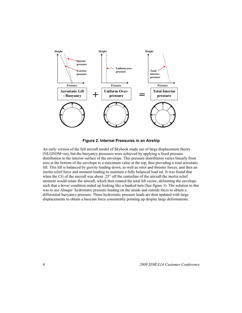
There is a significant interaction between the aerostatic lift pressures and the envelope shape and size. The below figure illustrates the internal pressures present in an airship:
4 2009 SIMULIA Customer Conference
Height
Pressure
Interior pressure
Exterior pressure
Aerostatic Lift - Buoyancy
Height
Pressure
Uniform over-pressure
Uniform Over-pressure + =
Height
Pressure
Total interior-pressure
Total Interior pressure
Figure 2. Internal Pressures in an Airship
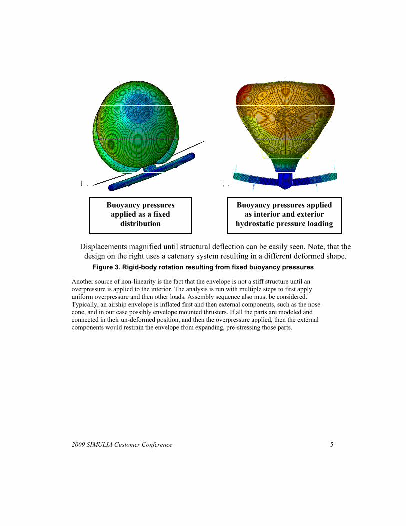
An early version of the full aircraft model of Skyhook made use of large displacement theory (NLGEOM=on), but the buoyancy pressures were achieved by applying a fixed pressure distribution to the interior surface of the envelope. This pressure distribution varies linearly from zero at the bottom of the envelope to a maximum value at the top, thus providing a total aerostatic lift. This lift is balanced by gravity loading down, as well as rotor and thruster forces, and then an inertia relief force and moment loading to maintain a fully balanced load set. It was found that when the CG of the aircraft was about .25” off the centerline of the aircraft the inertia relief moment would rotate the aircraft, which then rotated the total lift vector, deforming the envelope such that a hover condition ended up looking like a banked turn (See figure 3). The solution to this was to use Abaqus’ hydrostatic pressure loading on the inside and outside faces to obtain a differential buoyancy pressure. These hydrostatic pressure loads are then updated with large displacements to obtain a buoyant force consistently pointing up despite large deformations.
2009 SIMULIA Customer Conference 5
Buoyancy pressures applied as a fixed
distribution
Buoyancy pressures applied as interior and exterior
hydrostatic pressure loading
Displacements magnified until structural deflection can be easily seen. Note, that the design on the right uses a catenary system resulting in a different deformed shape.
Figure 3. Rigid-body rotation resulting from fixed buoyancy pressures
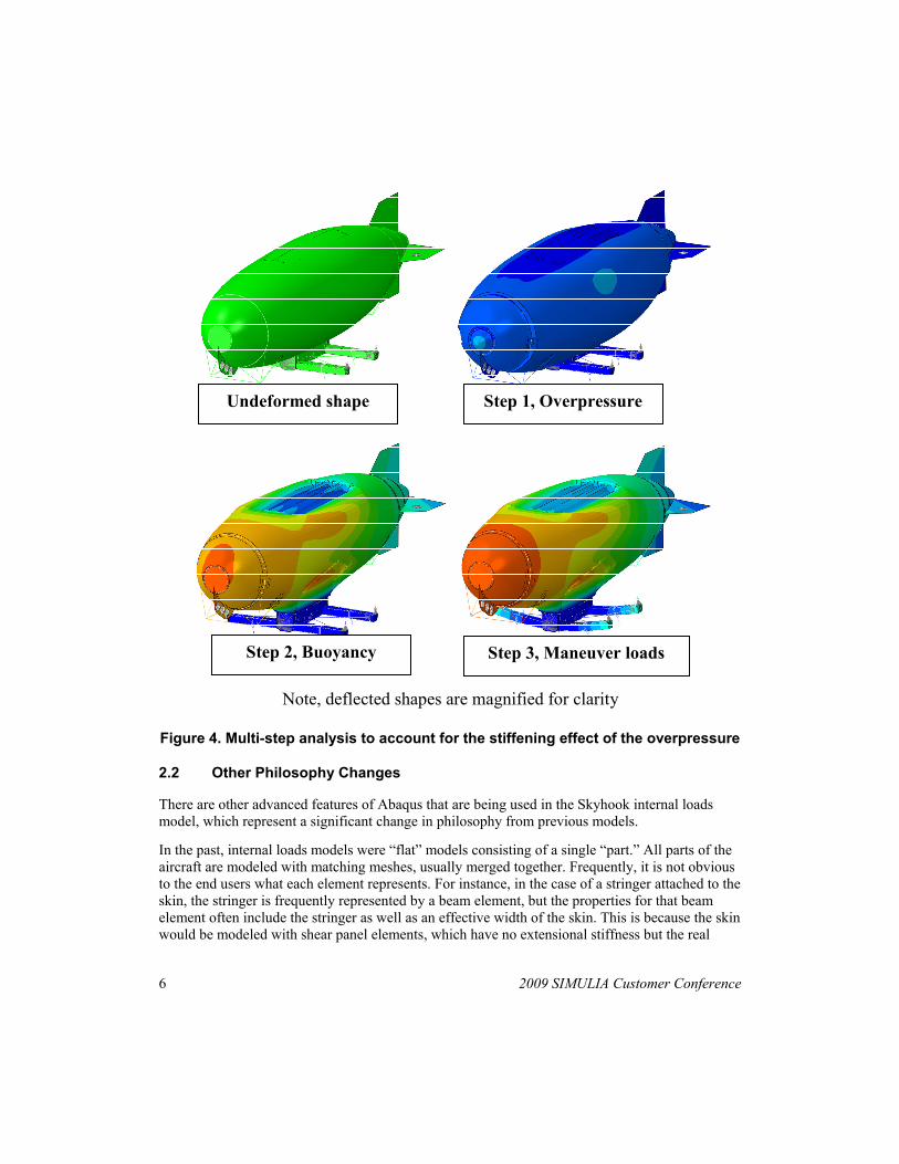
Another source of non-linearity is the fact that the envelope is not a stiff structure until an overpressure is applied to the interior. The analysis is run with multiple steps to first apply uniform overpressure and then other loads. Assembly sequence also must be considered. Typically, an airship envelope is inflated first and then external components, such as the nose cone, and in our case possibly envelope mounted thrusters. If all the parts are modeled and connected in their un-deformed position, and then the overpressure applied, then the external components would restrain the envelope from expanding, pre-stressing those parts.
6 2009 SIMULIA Customer Conference
Note, deflected shapes are magnified for clarity
Undeformed shape Step 1, Overpressure
Step 2, Buoyancy Step 3, Maneuver loads
Figure 4. Multi-step analysis to account for the stiffening effect of the overpressure
2.2 Other Philosophy Changes
There are other advanced features of Abaqus that are being used in the Skyhook internal loads model, which represent a significant change in philosophy from previous models.
In the past, internal loads models were “flat” models consisting of a single “part.” All parts of the aircraft are modeled with matching meshes, usually merged together. Frequently, it is not obvious to the end users what each element represents. For instance, in the case of a stringer attached to the skin, the stringer is frequently represented by a beam element, but the properties for that beam element often include the stringer as well as an effective width of the skin. This is because the skin would be modeled with shear panel elements, which have no extensional stiffness but the real
2009 SIMULIA Customer Conference 7
aircraft skin does to some degree. Also, a regimented numbering system is used for all elements and nodes. Node and element numbering would frequently have a numbering system, such as the first three stations being the X-coordinate (station) of the frame it is in and such. Although these methods allow for a very minimal degree of freedom (DOF) count, and thus a computationally efficient model, it becomes extremely laborious and time consuming to update the model as the design changes.
In the Skyhook HLV internal loads model, each part is distinctly modeled, and then the full aircraft is assembled using surface based MPCs (*tie). Furthermore, part and assembly modeling is being used, to reduce modeling time for highly repetitive parts. This allows us to model a re-used part once and create multiple instances of it. The overall effect of these changes is to produce a model, which can be modified very quickly, allowing a much higher quality internal loads prediction earlier in the design process, when even the gross shape of each part is changing radically.
3. Airship mooring analysis with Abaqus
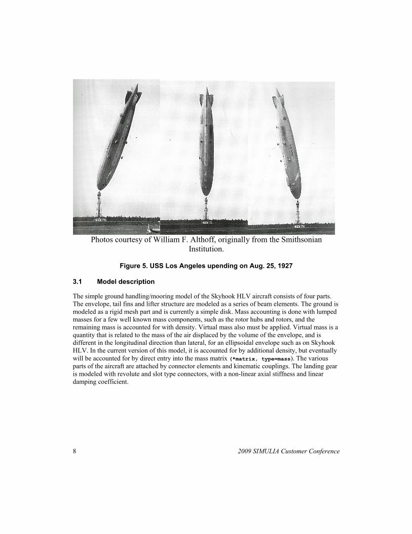
One of the most critical parts of designing an airship is understanding its behavior on and near the ground, during mooring and ground handling operations. History has shown that many airships were lost during mooring and ground handling operations, due to the very large drag area of the envelope. Common problems with airships on the ground include slapping the ground in winds while moored at the mast and in high winds, a kiting effect can make the aircraft rise nearly vertical, and then turn over to the other side of the mast. This happened to the 656 ft. long, 91,000 lb. USS Los Angeles on Aug. 25, 1927, where over a period of seven minutes the ship rose up on its nose with a full crew onboard and settled on the other side of the mast. Another hazard airships encounter is on the occasion of having to be moved into a hangar, many ships have been lost due to wind gusts at the entrance of the hangar. On the Skyhook program, Abaqus is one of the programs being used to model the airship and its behavior in wind.
8 2009 SIMULIA Customer Conference
Photos courtesy of William F. Althoff, originally from the Smithsonian
Institution.
Figure 5. USS Los Angeles upending on Aug. 25, 1927
3.1 Model description
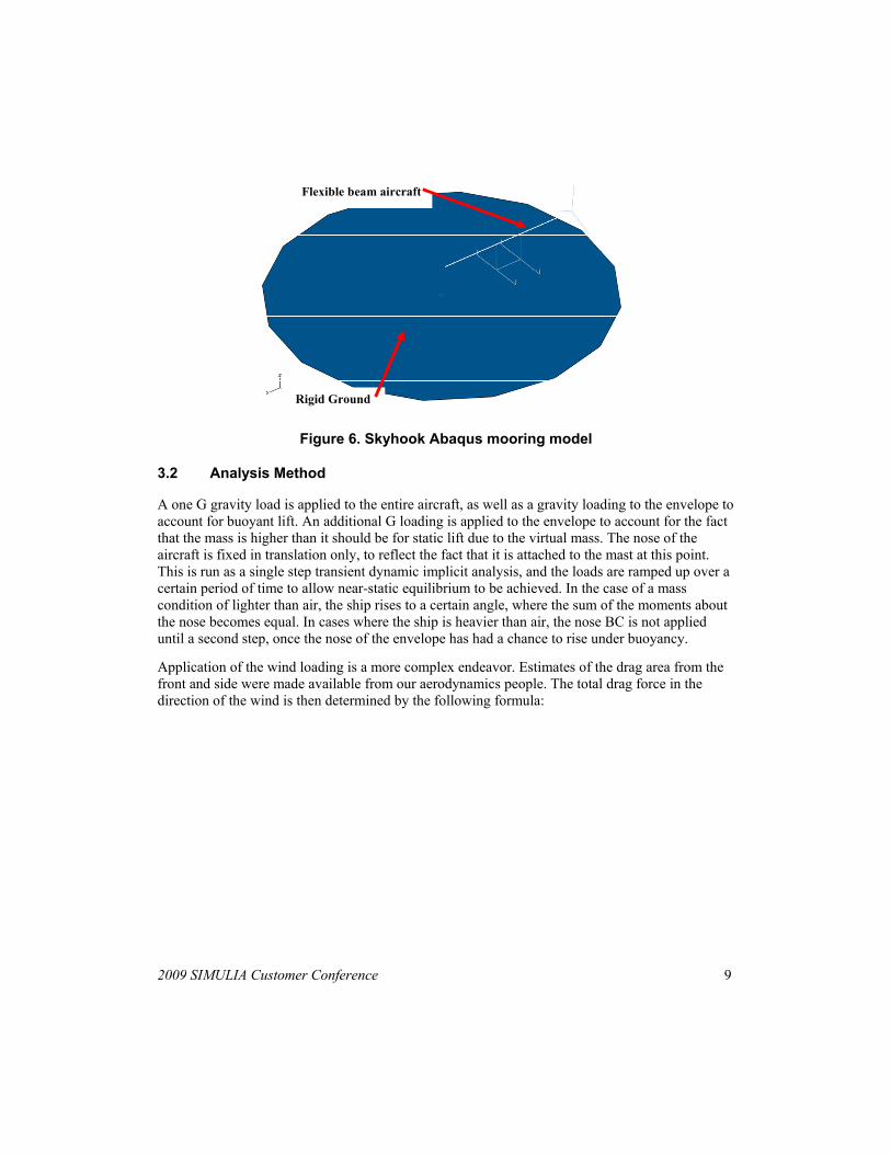
The simple ground handling/mooring model of the Skyhook HLV aircraft consists of four parts. The envelope, tail fins and lifter structure are modeled as a series of beam elements. The ground is modeled as a rigid mesh part and is currently a simple disk. Mass accounting is done with lumped masses for a few well known mass components, such as the rotor hubs and rotors, and the remaining mass is accounted for with density. Virtual mass also must be applied. Virtual mass is a quantity that is related to the mass of the air displaced by the volume of the envelope, and is different in the longitudinal direction than lateral, for an ellipsoidal envelope such as on Skyhook HLV. In the current version of this model, it is accounted for by additional density, but eventually will be accounted for by direct entry into the mass matrix (*matrix, type=mass). The various parts of the aircraft are attached by connector elements and kinematic couplings. The landing gear is modeled with revolute and slot type connectors, with a non-linear axial stiffness and linear damping coefficient.
2009 SIMULIA Customer Conference 9
Rigid Ground
Flexible beam aircraft
Figure 6. Skyhook Abaqus mooring model
3.2 Analysis Method
A one G gravity load is applied to the entire aircraft, as well as a gravity loading to the envelope to account for buoyant lift. An additional G loading is applied to the envelope to account for the fact that the mass is higher than it should be for static lift due to the virtual mass. The nose of the aircraft is fixed in translation only, to reflect the fact that it is attached to the mast at this point. This is run as a single step transient dynamic implicit analysis, and the loads are ramped up over a certain period of time to allow near-static equilibrium to be achieved. In the case of a mass condition of lighter than air, the ship rises to a certain angle, where the sum of the moments about the nose becomes equal. In cases where the ship is heavier than air, the nose BC is not applied until a second step, once the nose of the envelope has had a chance to rise under buoyancy.
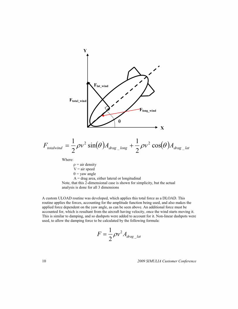
Application of the wind loading is a more complex endeavor. Estimates of the drag area from the front and side were made available from our aerodynamics people. The total drag force in the direction of the wind is then determined by the following formula:
10 2009 SIMULIA Customer Conference
X
Y
θ
Ftotal_wind
Flat_wind
Flong_wind
( ) ( ) latdraglongdragtotalwind AvAvF _2
_2 cos
21sin
21 θρθρ +=
Where: ρ = air density V = air speed θ = yaw angle A = drag area, either lateral or longitudinal
Note, that this 2-dimensional case is shown for simplicity, but the actual analysis is done for all 3 dimensions
A custom ULOAD routine was developed, which applies this total force as a DLOAD. This routine applies the forces, accounting for the amplitude function being used, and also makes the applied force dependent on the yaw angle, as can be seen above. An additional force must be accounted for, which is resultant from the aircraft having velocity, once the wind starts moving it. This is similar to damping, and so dashpots were added to account for it. Non-linear dashpots were used, to allow the damping force to be calculated by the following formula:
latdragAvF _2
21 ρ=
2009 SIMULIA Customer Conference 11
This allows the damping coefficient to be a function of velocity, which is a standard feature of Abaqus.
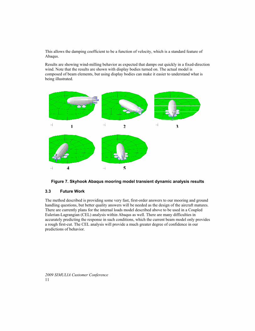
Results are showing wind-milling behavior as expected that damps out quickly in a fixed-direction wind. Note that the results are shown with display bodies turned on. The actual model is composed of beam elements, but using display bodies can make it easier to understand what is being illustrated.
1 2 3
4 5
Figure 7. Skyhook Abaqus mooring model transient dynamic analysis results
3.3 Future Work
The method described is providing some very fast, first-order answers to our mooring and ground handling questions, but better quality answers will be needed as the design of the aircraft matures. There are currently plans for the internal loads model described above to be used in a Coupled Eulerian-Lagrangian (CEL) analysis within Abaqus as well. There are many difficulties in accurately predicting the response in such conditions, which the current beam model only provides a rough first-cut. The CEL analysis will provide a much greater degree of confidence in our predictions of behavior.
12 2009 SIMULIA Customer Conference
4. References
1. Frank A. Smith Jr. and Paul M. Hopkins, “Non-Linear Internal Loads Modeling Methods,” Conference Proceedings, 2006 Abaqus Users’ Conference, pp. 459-478., Boston, Mass., USA, 2006.
2. Gabriel A Khoury and J. David Gillett, “Airship Technology,” Cambridge University Press, Cambridge, UK, 1999.
3. John D. Hunt, “Structural Analysis of Aerostat Flexible Structure by the Fintie-Element Method,” American Institute of Aeronautice and Astronautics Journal of Aircraft, Vol. 19, No. 8, Annapolis, Md., 1981.
4. Jong-ho Woo and V. R. Murthy, “Static and Dynamic Analysis of Airships,” American Institute of Aeronautice and Astronautics Journal of Aircraft, Vol. 25, NO. 9, Annapolis, Md., 1987
5. N. Bessert and O. Frederich, “Nonlinear airship aeroelasticity,” Journal of Fluids and Structures, Vol. 21 (2005), pp.731-742, 2005.
6. Ronald G.E. Browning, “Preliminray Study of Ground Handling Characteristics of Bouyant Quad Rotor (BQR) Vehicles,” prepared for NASA Ames Research Center, NASA contractor report 166130, Goodyear Aerospace Corporation, Akron, Ohio, 1980.
7. William F. Althoff, “USS Los Angeles: The Navy’s Venerable Airship and Aviation Technology,” Potomac Books, Inc, Washington, D.C., 2004.
5. Acknowledgment
Many thanks are in order to Joshua Kunz, of The Boeing Company, and Dinesh Panneerselvam, of Dassault systems, Simulia for their hard work in helping to develop and implement the methods described here-in. The author also is grateful to everyone who helped review and correct this paper to make it better. Thank you.


![Hardinge HLV H Manual[1] Copy](https://img.pdfslide.us/doc/110x75/5466c90eb4af9f5d3f8b5517/hardinge-hlv-h-manual1-copy.jpg)