Embed Size (px)
Citation preview
ADJUSTMENT TOOLFor NUMERIK JENA Encoders with Online Compensation
SIMPLY PRECISE
USER MANUAL

SIMPLY PRECISE
Index
1. Features and Applications .................................................................................................... 3
1.1 Functions of the ADJUSTMENT TOOL ........................................................................ 3 1.2 Dynamic Offset and Amplitude Control (Online Compensation) .................................. 3 1.3 Scope of Delivery ......................................................................................................... 3 1.4 Suitable Encoders ........................................................................................................ 3
2. Safety ...................................................................................................................................... 4
2.1 General Information ..................................................................................................... 4 2.2 Notes on Legal Requirements ..................................................................................... 5 2.3 Notes on Transport, Storage and Handling .................................................................. 5 2.4 Notes on Operation ...................................................................................................... 5
3. EPIFLEX Software .................................................................................................................. 6
3.1 EPIFLEX - Installation Guide ....................................................................................... 6 3.2 EPIFLEX - Range of Functions .................................................................................... 7 3.3 Advanced Software Settings ...................................................................................... 10
4. Wiring Diagram .................................................................................................................... 11
4.1 Connecting Variants of the Diagnostic Connector ..................................................... 11 4.2 Connection of the Encoder to the ADJUSTMENT TOOL Hardware .......................... 12
5. Electronic Signal Adjustment ............................................................................................. 13
5.1 Hints to the Automatic Signal Adjustment .................................................................. 14
6. Interface Settings ................................................................................................................. 15
7. Pin Assignment of the Diagnostic Connector .................................................................. 15
8. Troubleshooting ................................................................................................................... 16
9. Ordering Information ........................................................................................................... 17
2

SIMPLY PRECISE
1. Features and Applications
Before delivery the encoders from NUMERIK JENA will be tested and electronically adjusted under ideal mounting conditions. Furthermore, the sensor modules offer the possibility of an electronic signal adjustment after the mounting into the application. This allows the user to optimize the encoder signals regarding to the mechanical mounting conditions (tolerances).
The ADJUSTMENT TOOL and the related EPIFLEX software was designed to simplify and make the signal adjustment more effective.
1.1 Functions of the ADJUSTMENT TOOL
• Automatic signal adjustment / optimization and programming of the sensor module• Display of the sinusoidal counting signals with amplitude, offset and phase position• Enables evaluation of the mechanical mounting conditions• Display and adjustment of the index signal
1.2 Dynamic Offset and Amplitude Control (Online Compensation)
The encoders of NUMERIK JENA are equipped with a dynamic amplitude and offset control (online compensation). The analog diode signals will be corrected to their nominal values in real time. This reduces measuring errors caused by contamination of the scale tape as well as from inaccuracies in the guide way. The phase position between the sine and cosine signals and the position of the index signalarenotinfluencedbytheonlinecompensation.
With help of the EPIFLEX Software the preadjusted nominal values of the online compensation can be influenced(seechapter3).
1.3 Scope of Delivery
• ADJUSTMENT TOOL black box• Diagnostic cable to connect the measuring system• USB cable to connect a PC• USB - D-SUB - adapter cable (15-pin)• Exchangeable 8-pin plug connectors
1.4 Suitable Encoders
The ADJUSTMENT TOOL is suitable for the following NUMERIK JENA - products:
3
LIA Series Kit R4LIK Series RIA SeriesKit L2 / L4 RIK 4

SIMPLY PRECISE
4
2. Safety
2.1 General Information
• Make sure to familiarize yourself thoroughly with the contents of the user manuals and data sheets before installing and starting up the encoder!
• The encoders as well as the accessory are guaranteed to function if the mounting and operating conditions are maintained as stated in the respective user manuals and data sheets .
• NUMERIK JENA GmbH is not liable for damages caused by unauthorized handling of the encoders and the accessory. Any unauthorized handling leads to forfeiture of all warranty claims!
• Connect NUMERIK JENA encoders only to subsequent electronics whose power supply is generated from PELV systems (EN 50178).
• NUMERIKJENAencoders fulfill the requirementsofstandard IEC61010-1only if thepower issupplied from a secondary circuit with current limitation as per IEC 610103rd Ed., Section 9.4 or with power limitation as per IEC 60950-12nd Ed., Section 2.5 or from a Class 2 secondary circuit as specifiedinUL1310.*
• The stated mounting tolerances must be maintained in order to achieve the accuracies listed in the specifications!Ifthemachinetolerancesexceedthetolerancesstatedintheusermanualsordatasheets, malfunctions during operation can occur and lead to measuring errors.
• NUMERIK JENA GmbH does not assume any liability for any damages or operating errors caused by incorrect mounting and/or startup operations.
• Please consider user manuals, data sheets and safety instructions of devices from other manufacturer which will be used in combination with encoders and accessories from NUMERIK JENA to ensure a reliable operation.
• Please pay attention to the safety instructions and warning symbols in the user manuals and data sheets from NUMERIK JENA!
Danger to the device or to the function of the device!
Pull the plug! Highlyinflammable!
In place of IEC 61010-13rdEd., Section 9.4, the corresponding sections of standards DIN EN 61010-1, EN61010-1, UL 61010-1 and CAN/CSA-C22.2 No. 61010-1 can be applied and in place of IEC 60950-12nd Ed., Section 2.5 the corresponding sections of standards DIN EN60950-1, EN60950-1, UL60950-1, CAN/CSA-C22.2 No. 60950-1 can be applied.
*
!! !
SIMPLY PRECISE
5
2.2 Notes on Legal Requirements
• The encoders and accessories from NUMERIK JENA conform to EC standards and carry the CE mark.
• The encoders and accessories from NUMERIK JENA fulfill the requirements of the (German)Product Safety Act (ProdSG) from November 8th, 2011.
• Standards (ISO, EN, etc.) apply only where explicitly stated in the respective user manual or data sheet of the product.
• This user manual supersedes all previous editions, which thereby become invalid.
• The basis for ordering from NUMERIK JENA is always the valid edition of the user manual or data sheet at that time when the contract is made.
2.3 Notes on Transport, Storage and Handling
• The products from NUMERIK JENA must be transported and stored in the original packaging only!
2.4 Notes on Operation
• Do not connect or disconnect plugs if the power is on!
• The encoders and accessories from NUMERIK JENA must be operated with the supply voltage stated in the respective user manual or data sheet only.
• Comply with applicable PIN assignment if auxiliary electronic units (e.g. controller or display) are connected!
!!
SIMPLY PRECISE
3. EPIFLEX Software
The EPIFLEX software was especially designed for the ADJUSTMENT TOOL. It offers the user versatile possibilities to bring the encoder into service. It also allows the user to display the sensor signals and evaluate them without using an oscilloscope or other expensive hardware. Furthermore it is possible to program respectively optimize the encoder to the existing mounting conditions automatically.
The EPIFLEX software is available for free via download on the NUMERIK JENA website under www.numerikjena.de. Furthermore, one can order the software with an optional USB flash drive.
The EPIFLEX software is suitable for the following operating systems:
• Windows 7 / 8 (32 or 64 bit)
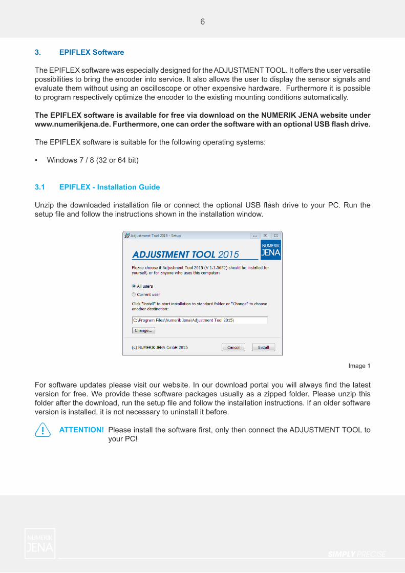
3.1 EPIFLEX - Installation Guide
Unzip thedownloaded installationfileorconnect theoptionalUSBflashdrive toyourPC.Run thesetupfileandfollowtheinstructionsshownintheinstallationwindow.
Forsoftwareupdatespleasevisitourwebsite.Inourdownloadportalyouwillalwaysfindthelatestversion for free. We provide these software packages usually as a zipped folder. Please unzip this folderafterthedownload,runthesetupfileandfollowtheinstallationinstructions.Ifanoldersoftwareversion is installed, it is not necessary to uninstall it before.
ATTENTION! Pleaseinstallthesoftwarefirst,onlythenconnecttheADJUSTMENTTOOLto your PC!
6
Image 1
SIMPLY PRECISE
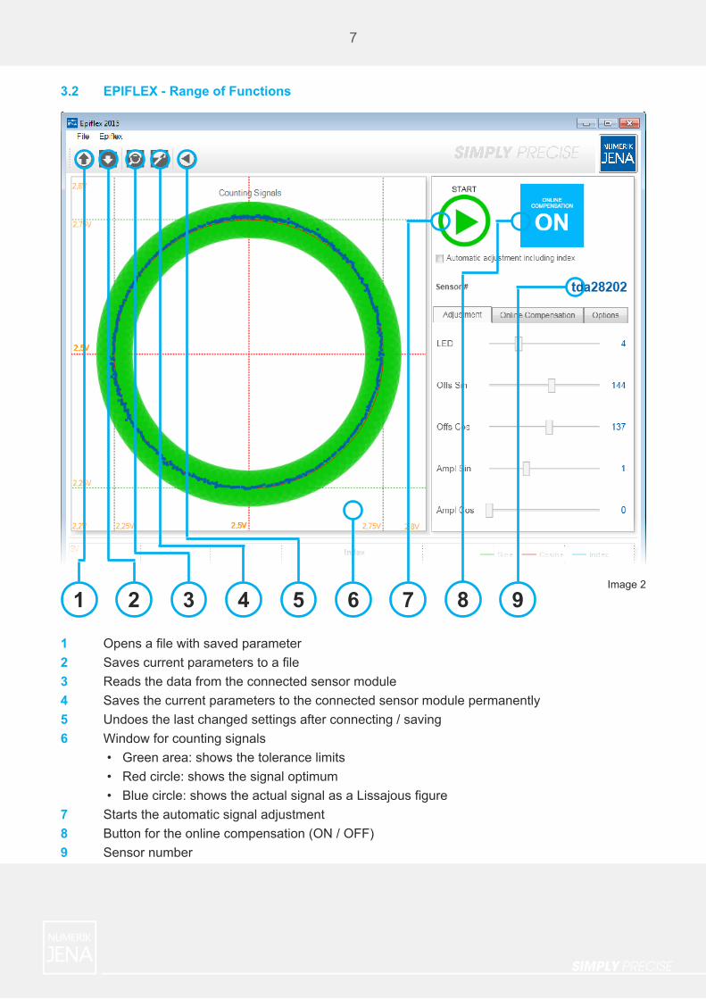
3.2 EPIFLEX - Range of Functions
7
Image 2
1 2 3 4 5 6 7 8 9
1 Opensafilewithsavedparameter2 Savescurrentparameterstoafile3 Reads the data from the connected sensor module4 Saves the current parameters to the connected sensor module permanently5 Undoes the last changed settings after connecting / saving6 Window for counting signals •Greenarea:showsthetolerancelimits •Redcircle:showsthesignaloptimum •Bluecircle:showstheactualsignalasaLissajousfigure7 Starts the automatic signal adjustment8 Button for the online compensation (ON / OFF)9 Sensor number

SIMPLY PRECISE
8
10 Signal window for the index impulse •Greensignalperiod:Sinesignal •Redsignalperiod:Cosinesignal •Bluesignal:Indeximpulse11 Controller for adjustment of the index •Change of position12 Controller for adjustment of the index •Change of width13 Drop-down menu for signal output (interface) •1VPP (for sensor modules with and also without integrated signal interpolation) •3VPP (for sensor modules with external interpolation electronics / PCB)14 Controller to change the time base of the software oscilloscope15 Readout for the time-based value
10 11 12 13 14 15 Image 3
Index Signal Window
SIMPLY PRECISE
9
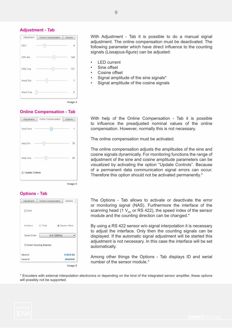
Adjustment - Tab
Online Compensation - Tab
Options - Tab
With Adjustment - Tab it is possible to do a manual signal adjustment. The online compensation must be deactivated. The followingparameterwhichhavedirectinfluencetothecountingsignals(Lissajous-figure)canbeadjusted:
• LED current• Sine offset• Cosine offset• Signalamplitudeofthesinesignals*• Signal amplitude of the cosine signals
With help of the Online Compensation - Tab it is possible to influence the preadjusted nominal values of the onlinecompensation. However, normally this is not necessary.
The online compensation must be activated.
The online compensation adjusts the amplitudes of the sine and cosine signals dynamically. For monitoring functions the range of adjustment of the sine and cosine amplitude parameters can be visualized by activating the option “Update Controls”. Because of a permanent data communication signal errors can occur. Thereforethisoptionshouldnotbeactivatedpermanently.*
The Options - Tab allows to activate or deactivate the error or monitoring signal (NAS). Furthermore the interface of the scanning head (1 VPP or RS 422), the speed index of the sensor moduleandthecountingdirectioncanbechanged.*
By using a RS 422 sensor w/o signal interpolation it is necessary to adjust the interface. Only then the counting signals can be displayed. If the automatic signal adjustment will be started this adjustment is not necessary. In this case the interface will be set automatically.
Among other things the Options - Tab displays ID and serial numberofthesensormodule.*
*Encoderswithexternalinterpolationelectronicsordependingonthekindoftheintegratedsensoramplifier,theseoptionswill possibly not be supported.
Image 4
Image 5
Image 6

SIMPLY PRECISE
10
3.3 Advanced Software Settings
By using the key combination [Ctrl] + [Shift] + [S] an additional window for advanced settings will be shown.
In the settings window one can activate or deactivate the following settings:
• Set Online Compensation after automatic adjustment• Force 1VPP setting at start of automatic adjustment• Restore interface setting after automatic adjustment• Warn if adjustment is canceled• Show Sum control in index signal window (restart of EPIFLEX 2015 is required)• Language settings, automatic or manual (English / German)
Image 7
SIMPLY PRECISE
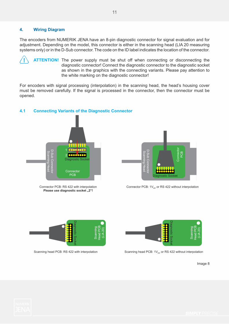
4. Wiring Diagram
The encoders from NUMERIK JENA have an 8-pin diagnostic connector for signal evaluation and for adjustment. Depending on the model, this connector is either in the scanning head (LIA 20 measuring systems only) or in the D-Sub connector. The code on the ID label indicates the location of the connector.
ATTENTION!
For encoders with signal processing (interpolation) in the scanning head, the head’s housing cover must be removed carefully. If the signal is processed in the connector, then the connector must be opened.
4.1 Connecting Variants of the Diagnostic Connector
The power supply must be shut off when connecting or disconnecting the diagnostic connector! Connect the diagnostic connector to the diagnostic socket as shown in the graphics with the connecting variants. Please pay attention to the white marking on the diagnostic connector!
11
Image 8
Connector PCB: RS 422 with interpolationPlease use diagnostic socket „2“!
Connector PCB: 1VPP or RS 422 without interpolation
Scanning head PCB: RS 422 with interpolation Scanning head PCB: 1VPP or RS 422 without interpolation
Sca
nnin
g H
ead
PC
B(L
IA 2
0)
Diagnostic S
ocket
Sca
nnin
g H
ead
PC
B(L
IA 2
0)
Diagnostic S
ocket
D-S
ub Connector
Scanning H
ead
Diagnostic Socket
1
2
ConnectorPCB
D-S
ub Connector
Scanning H
ead
Diagnostic SocketC
onne
ctor
PC
B

SIMPLY PRECISE
4.2 Connection of the Encoder to the ADJUSTMENT TOOL Hardware
ATTENTION! Please pay attention to the following during the signal adjustment:
Any noise disturbances which are interfering with the measuring system can lead to incorrect signal settings. This will cause non-optimal signal parameters during function.
During the signal adjustment the signals of the encoder should not be used to control the drive motor. Unintentional misadjustments could cause wrong signal values in the controller and lead to malfunction of the drive system.
The stage should be moved without motorized drive during the signal adjustment. If a motorized drive is necessary, a manual operation has to be used.
Encoder system, stage, ADJUSTMENT TOOL and controller must have the same ground and earth potential. For safety purposes use the included USB - D-SUB - adapter cable during the adjustment to supply the measuring system with power over your PC, not your controller!
If you are not in possession of the USB - D-SUB - adapter cable, you can order it separately from NUMERIK JENA.
12
Image 9
Black Box
US
B
Dia
gnos
tic S
ocke
t
PC
US
BU
SB
Sca
nnin
g H
ead
PC
B(L
IA 2
0)
D-S
ub Connector
Adapter C
able
Diagnostic S
ocketD-S
ub C
onne
ctor
S
cann
ing
Hea
d
Diagnostic Socketor
ConnectorPCB

SIMPLY PRECISE
5. Electronic Signal Adjustment
WiththeEPIFLEXsoftwareyouareabletoadjustsignalinfluencingparametersmanually(seepage7). Ocassionally, that can be inconvenient, time-consuming and imprecise. Therefore, the EPIFLEX software provides an automatic adjustment function which allows you to adjust and optimize all parameter settings automatically very fast as well as easy.
To start the automatic adjustment please proceed as described in the following:
1.
2.3.
4.
5.
ATTENTION! Before you start the electronic adjustment please pay attention to any contamination on the scale. This can affect the adjustment process negatively. Clean the surface of the scale with a soft microfibre cloth and acetone if necessary.
13
Image 10
Click on the green Start - Button to start the automatic adjustment procedure.Subsequently a status window appears.Please follow the instructions displayed in the status window!Move the read head to the scale back and forth. In doing so it is important to cross a reference mark to ensure that the system can also adjust this parameter correctly. Please cross the reference mark in both directions!At the bottom of the main window a green progress bar will be displayed. This bar shows the progress of the adjustment. The status window displays the progress of each adjusted parameter.If the adjustment is done, please click on the Save - Button. By doing so the new adjusted parameter will be saved to the sensor module.

SIMPLY PRECISE
Iftheautomaticadjustmentprocedureisfinishedsuccessfully,youcanusetheencoderatfullcapability.If you change something regarding your mounting conditions afterwards, e.g. disassembling and renewed assembling of the scanning head, it is recommended to do the automatic adjustment again.
14
5.1 Hints to the Automatic Signal Adjustment
The movement of the measuring system during the automatic signal adjustment should be as steady as possible. In the window for the index impulse 2 to 6 signal periods should be displayed. Otherwise adjust the movement speed or regulate the time base of the software oscilloscope, please.
If the status window displays the message “Missing signals or too less/many periods to calculate the parameters”, it is an indication that the movement of the measuring system is too slow or too fast. In this case please adjust the movement speed in an appropriate way. Furthermore, you should pay attention that you cross the reference mark during the movement.
If you get error messages in the status window after the adjustment it may have several reasons. In this case please start the automatic adjustment procedure again to verify a legitimate failure. Additionally, please pay attention to our mounting instructions in the data sheet of the measuring system. Often, problems occur because of a transgression of the mechanical mounting tolerances.
In chapter 8 we have compiled some potential error causes. If these error causes do not apply to your application, please contact us.
Image 11

SIMPLY PRECISE
6. Interface Settings
The EPIFLEX software recognizes the output interface of the sensor automatically during startup of the automatic signal adjustment. If the EPIFLEX software is used to check the sensor signals only, possibly an interface setting must be done (see page 6 and 7).
Following settings are valid:
Signal processing Interface Output interface
Scanning head
1 VPP 1 VPP
1 VPP / 3 VPP RS 422 with interpolation
RS 422 RS 422 with interpolation
Connector
1 VPP 1 VPP
3 VPP RS 422 with interpolation
RS 422 RS 422 with interpolation
7. Pin Assignment of the Diagnostic Connector
Pin Signal Description
1 SCL Serial Clock (white marking on diagnostic connector)
2 SDA Serial Data
3 RI Index rough impulse
4 Um Middle voltage
5 A+ Sine+
6 B+ Cosine+
7 CS not used
8 GND GND
15
Chart 1
Chart 2
SIMPLY PRECISE
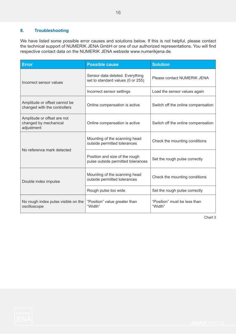
8. Troubleshooting
We have listed some possible error causes and solutions below. If this is not helpful, please contact thetechnicalsupportofNUMERIKJENAGmbHoroneofourauthorizedrepresentations.Youwillfindrespective contact data on the NUMERIK JENA webside www.numerikjena.de.
Error Possible cause Solution
Incorrect sensor values
Sensor data deleted. Everything set to standard values (0 or 255) Please contact NUMERIK JENA
Incorrect sensor settings Load the sensor values again
Amplitude or offset cannot be changed with the controllers Online compensation is active Switch off the online compensation
Amplitude or offset are not changed by mechanical adjustment
Online compensation is active Switch off the online compensation
No reference mark detected
Mounting of the scanning head outside permitted tolerances Check the mounting conditions
Position and size of the rough pulse outside permitted tolerances Set the rough pulse correctly
Double index impulse
Mounting of the scanning head outside permitted tolerances Check the mounting conditions
Rough pulse too wide Set the rough pulse correctly
No rough index pulse visible on the oscilloscope
“Position” value greater than “Width”
“Position” must be less than “Width”
16
Chart 3
SIMPLY PRECISE
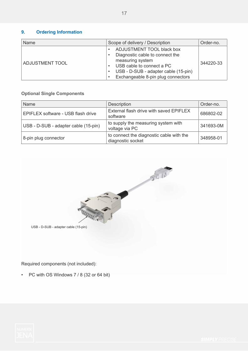
USB - D-SUB - adapter cable (15-pin)
17
Required components (not included):
• PC with OS Windows 7 / 8 (32 or 64 bit)
Optional Single Components
9. Ordering Information
Name Scope of delivery / Description Order-no.
ADJUSTMENT TOOL
• ADJUSTMENT TOOL black box• Diagnostic cable to connect the
measuring system• USB cable to connect a PC• USB - D-SUB - adapter cable (15-pin)• Exchangeable 8-pin plug connectors
344220-33
Name Description Order-no.
EPIFLEXsoftware-USBflashdrive ExternalflashdrivewithsavedEPIFLEXsoftware 686802-02
USB - D-SUB - adapter cable (15-pin) to supply the measuring system with voltage via PC 341693-0M
8-pin plug connector to connect the diagnostic cable with the diagnostic socket 348958-01

SIMPLY PRECISE
NUMERIK JENA GmbHIm Semmicht 407751 JenaGermany Phone: +49 3641 4728-0Fax: +49 3641 4728-202E-Mail: [email protected] www.numerikjena.de
Subject to change without prior notice. ℗ & © NUMERIK JENA GmbH
version 03_3 2016


![Hydroinformatik II: [1.0ex] Grundlagen Numerik [1.0ex] V8 ... fileV8: Grundlagen Numerik [BHYWI-08-05]26.05.2017 Hydroinformatik II: Grundlagen Numerik V8 [BHYWI-08-05] 1Helmholtz](https://img.pdfslide.us/doc/110x75/5ca0314688c99312188cba49/hydroinformatik-ii-10ex-grundlagen-numerik-10ex-v8-grundlagen-numerik.jpg)


![studi numerik Hip Stem [autosaved]](https://img.pdfslide.us/doc/110x75/55b8a486bb61ebb8498b476e/studi-numerik-hip-stem-autosaved.jpg)

