Embed Size (px)
Citation preview
Adju
stab
le Mo
lded
Cas
e Circ
uit B
reak
erM
eta
- M
EC
Ser
ies
Adjustable Molded Case
Circuit Breaker (GB-Type)
99 -1299 -12
ISO 14001, ISO 9001
AAmmppeerree FFrraammee
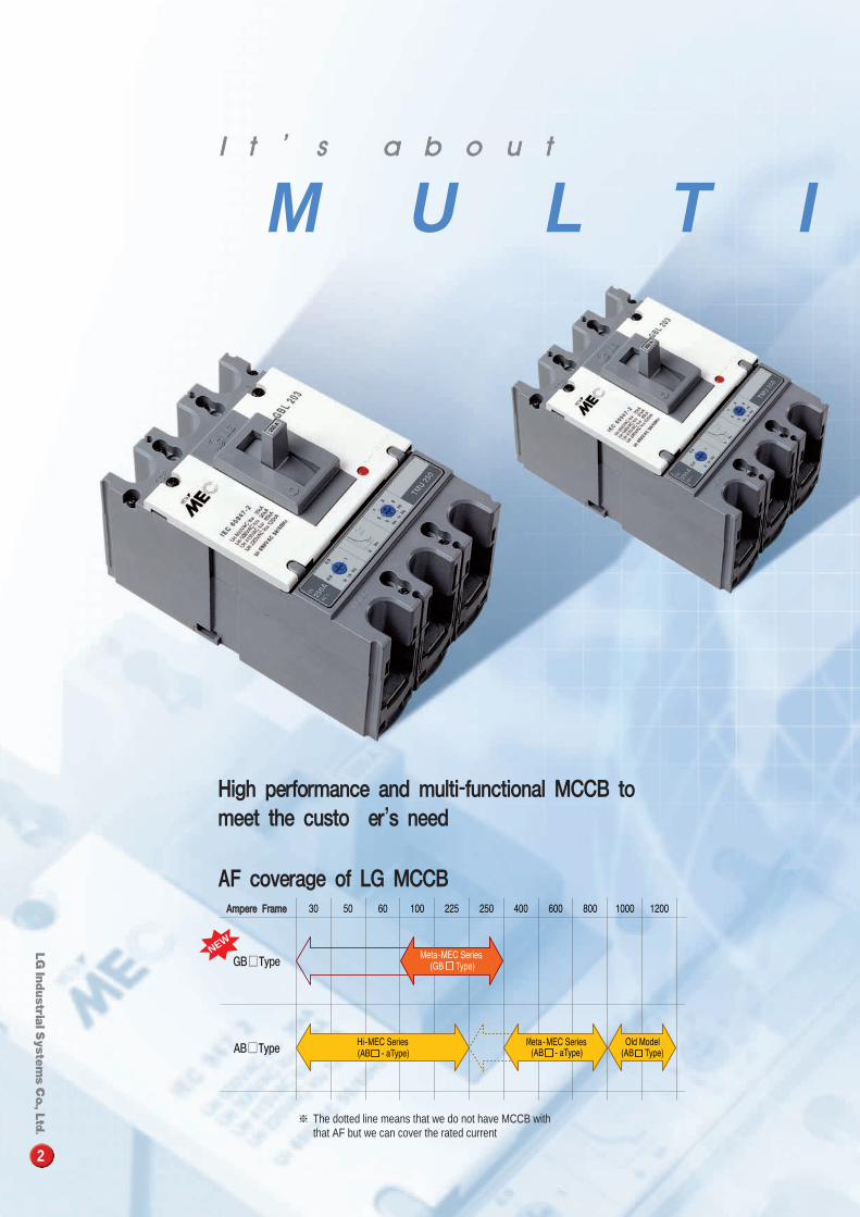
※ The dotted line means that we do not have MCCB with that AF but we can cover the rated current
High performance and multi-functional MCCB tomeet the customer's need
AF coverage of LG MCCB
2
M U L T I
NEW
AB�Type
II tt ’’ ss aa bb oo uu tt
GB�Type
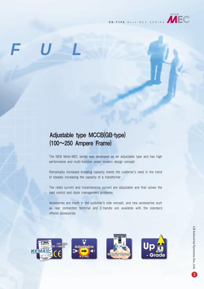
The NEW Meta-MEC series was developed as an adjustable type and has high
performance and multi-function under modern design concept
Remarkably increased breaking capacity meets the customer's need in the trend
of steadily increasing the capacity of a transformer
The rated current and instantaneous current are adjustable and that solves the
load control and stock management problems
Accessories are made in the customer's side concept, and new accessories such
as rear connection terminal and E-handle are available with the standard
offered accessories
3
Adjustable type MCCB(GB-type)(100�250 Ampere Frame)
F U L
G B - T Y P E M e t a - M E C S E R I E S
1Characteristics
4
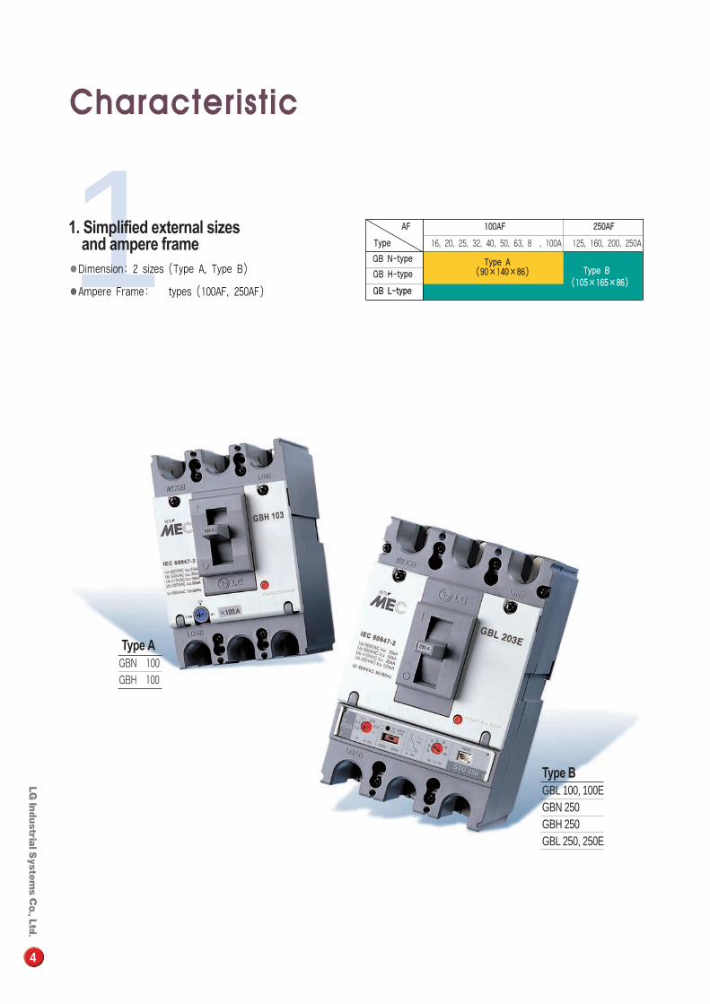
AAFF 110000AAFF 225500AAFF
TTyyppee 16, 20, 25, 32, 40, 50, 63, 80, 100A 125, 160, 200, 250A
GGBB NN--ttyyppee TTyyppee AAGGBB HH--ttyyppee ((9900××114400××8866)) TTyyppee BB
GGBB LL--ttyyppee((110055××116655××8866))
Type AGBN 100
GBH 100
Type B GBL 100, 100EGBN 250GBH 250GBL 250, 250E
1. Simplified external sizes and ampere frame
●Dimension: 2 sizes (Type A, Type B)
●Ampere Frame: 2 types (100AF, 250AF)
Type A Type B
5
D
T1T1
T2 T2
D
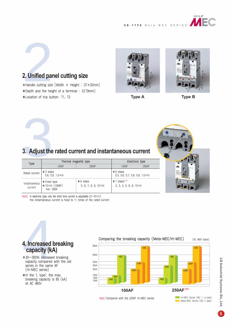
3Note) In electronic type, only the short time current is adjustable (2�10×Ir)
the instantaneous current is fixed to 11 times of the rated current
TTyyppeeTThheerrmmaall mmaaggnneettiicc ttyyppee EElleeccttrroonniicc ttyyppee
100AF 250AF 100AF 250AF
●3 steps ●6 stepsRated current0.8, 0.9, 1.0×In 0.5, 0.6, 0.7, 0.8, 0.9, 1.0×In
●Fixed type ●6 steps ●7 steps(Note)
●10×In (100AF) 5, 6, 7, 8, 9, 10×In 2, 3, 4, 5, 6, 8, 10×Irmin. 500A
3. Adjust the rated current and instantaneous current
22. Unified panel cutting size●Handle cutting size (Width × Height : 37×52mm)
●Depth and the height of a terminal : D(79mm)
●Location of trip button: T1, T2
85kA
65kA
50kA
35kA
42kA
18kA14kA10kA
4Hi-MEC Series (AB � -a type)Meta-MEC Series (GB � type)
4. Increased breaking capacity (kA)
●30�300% increased breaking capacity compared with the old series in the same AF (Hi-MEC series)
●In the 'L type', the max. breaking capacity is 85 (kA) at AC 460V
Note) Compared with the 225AF Hi-MEC series
(AC 460V basis)
250AF (Note)100AF
CCoommppaarriinngg tthhee bbrreeaakkiinngg ccaappaacciittyy ((MMeettaa--MMEECC//HHii--MMEECC))
G B - T Y P E M e t a - M E C S E R I E S
Instantaneouscurrent
CChhaarraacctteerriissttiiccss
6
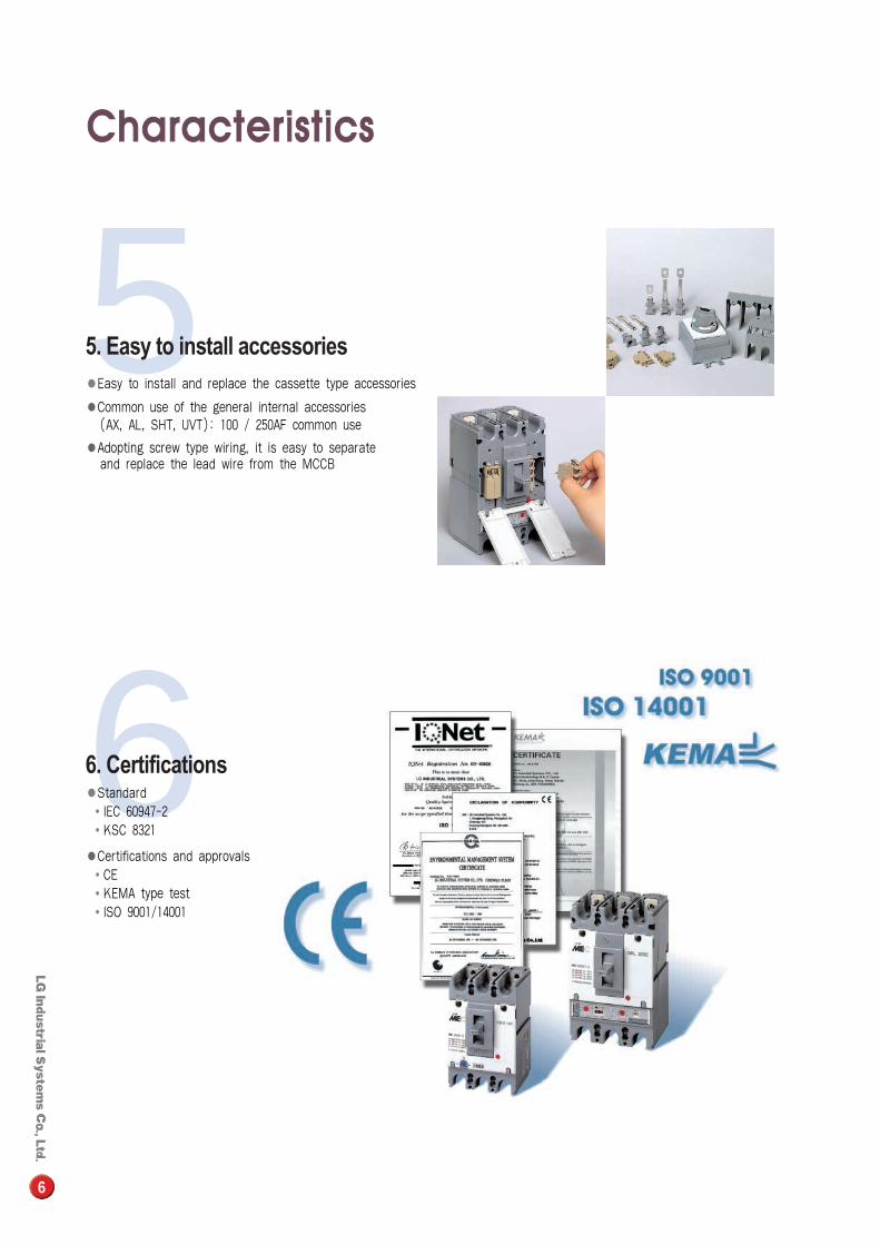
66. Certifications●Standard�IEC 60947-2�KSC 8321
●Certifications and approvals �CE�KEMA type test�ISO 9001/14001
55. Easy to install accessories●Easy to install and replace the cassette type accessories
●Common use of the general internal accessories (AX, AL, SHT, UVT): 100 / 250AF common use
●Adopting screw type wiring, it is easy to separate and replace the lead wire from the MCCB
7
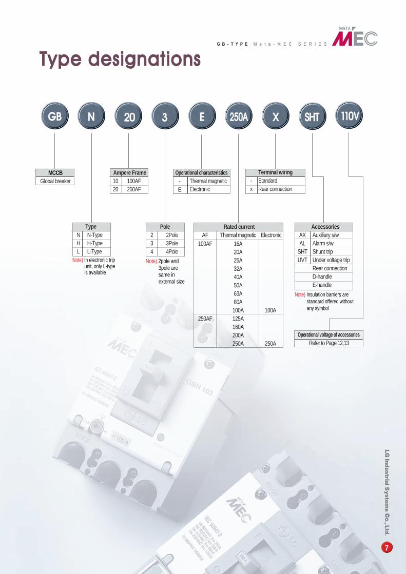
MCCBGlobal breaker
Ampere Frame10 100AF20 250AF
Terminal wiring- Standard x Rear connection
Note) In electronic trip unit, only L-type is available
Rated currentAF Thermal magnetic Electronic
100AF 16A20A25A32A40A50A63A80A100A 100A
250AF 125A160A200A250A 250A
Note) 2pole and 3pole are same in external size
TypeN N-TypeH H-TypeL L-Type
Pole2 2Pole3 3Pole4 4Pole
AccessoriesAX Auxiliary s/wAL Alarm s/w
SHT Shunt trip UVT Under voltage trip
Rear connectionD-handleE-handle
Operational voltage of accessoriesRefer to Page 12,13
Note) Insulation barriers are standard offered without any symbol
G B - T Y P E M e t a - M E C S E R I E S
Operational characteristics- Thermal magneticE Electronic
TTyyppee ddeessiiggnnaattiioonnss
GGBB NN 2200 33 EE 225500AA XX SSHHTT 111100VV
8
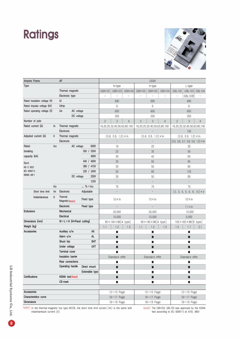
100AF
N-type H-type L-type
GBN102 GBN103 GBN104 GBH102 GBH103 GBH104 GBL102 GBL103 GBL104
- - - - - - - GBL103E -
690 690 690
6 6 6
600 600 600
250 250 250
2 3 4 2 3 4 2 3 4
16,20,25,32,40,50,63,80,100 16,20,25,32,40,50,63,80,100 16,20,25,32,40,50,63,80,100
- - 100
(0.8, 0.9, 1.0)×In (0.8, 0.9, 1.0)×In (0.8, 0.9, 1.0)×In
- - (0.5, 0.6, 0.7, 0.8, 0.9, 1.0)×In
18 25 35
22 35 50
30 42 65
35 50 85
35 50 85
50 85 125
35 50 85
- - -
75 75 75
- - (2, 3, 4, 5, 6, 8, 10)×Ir
10×In 10×In 10×In
- - 11×In
20,000 20,000 10,000
10,000 10,000 5,000
90×140×86(A type) 90×140×86(A type) 105×165×86(B type)
1.1 1.2 1.5 1.1 1.2 1.5 1.5 1.7 2.1
� � �
� � �
� � �
� � �
� � �
Standard offer Standard offer Standard offer
� � �
� � �
� � �
� � �
� � �
12�15 Page 12�15 Page 12�15 Page
16�17 Page 16�17 Page 16�17 Page
18�19 Page 18�19 Page 18�19 Page
Note1) In the thermal-magnetic trip type MCCB, the short time limit current (Im) is the same with instantaneouls current (It)
Note2) The GBH103, GBL103 was approved by the KEMA test according to IEC 60947-2 at 415V, 480V
Ampere Frame AF
Type
Thermal magnetic
Electronic type
Rated insulation voltage (V) Ui
Rated impulse voltage (kV) Uimp
Rated operating voltage (V) Ue AC voltage
DC voltage
Number of pole
Rated current (A) In Thermal magnetic
Electronic
Adjusted current (A) Ir Thermal magnetic
Electronic
Rated Icu AC voltage 600V
breaking 500 / 550V
capacity (kA) 480V
(Sym)440 / 460V
KS C 8321 380 / 415V
IEC 60947-2 220 / 240VNEMA AB-1 DC voltage 250V
125V
Ics ... %×Icu
Short time limit Im Electronic Adjustable
Instantaneous It Thermal Fixed type
Magnetic (Note1)
Electronic Fixed type
Endurance Mechanical
Electrical
Dimensions (mm) W×L×H (H=Panel cutting)
Weight (kg)
Accessories Auxiliary s/w AX
Alarm s/w AL
Shunt trip SHT
Under voltage UVT
Terminal cover
Insulation barrier
Rear connections
Operating handle Direct mount
Extensible type
Certifications KEMA test (Note2)
CE-mark
Accessories
Characteristics curve
Dimensions
RRaattiinnggss
9
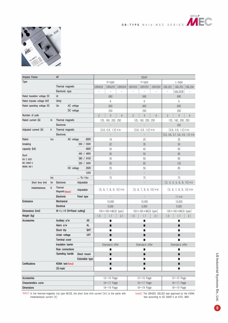
250AF
N-type H-type L-type
GBN202 GBN203 GBN204 GBH202 GBH203 GBH204 GBL202 GBL203 GBL204
- - - - - - - GBL203E -
690 690 690
6 6 6
600 600 600
250 250 250
2 3 4 2 3 4 2 3 4
125, 160, 200, 250 125, 160, 200, 250 125, 160, 200, 250
- - 250
(0.8, 0.9, 1.0)×In (0.8, 0.9, 1.0)×In (0.8, 0.9, 1.0)×In
- - (0.5, 0.6, 0.7, 0.8, 0.9, 1.0)×In
18 25 35
22 35 50
30 42 65
35 50 85
35 50 85
50 85 125
35 50 85
- - -
75 75 75
- - (2, 3, 4, 5, 6, 8, 10)×Ir
(5, 6, 7, 8, 9, 10)×In (5, 6, 7, 8, 9, 10)×In (5, 6, 7, 8, 9, 10)×In
- - 11×In
10,000 10,000 10,000
5,000 5,000 5,000
105×165×86(B type) 105×165×86(B type) 105×165×86(B type)
1.5 1.7 2.1 1.5 1.7 2.1 1.5 1.7 2.1
� � �
� � �
� � �
� � �
� � �
Standard offer Standard offer Standard offer
� � �
� � �
� � �
� � �
� � �
12�15 Page 12�15 Page 12�15 Page
16�17 Page 16�17 Page 16�17 Page
18�19 Page 18�19 Page 18�19 Page
Note1) In the thermal-magnetic trip type MCCB, the short time limit current (Im) is the same with instantaneouls current (It)
Note2) The GBH203, GBL203 was approved by the KEMA test according to IEC 60947-2 at 415V, 480V
G B - T Y P E M e t a - M E C S E R I E S
Ampere Frame AF
Type
Thermal magnetic
Electronic type
Rated insulation voltage (V) Ui
Rated impulse voltage (kV) Uimp
Rated operating voltage (V) Ue AC voltage
DC voltage
Number of pole
Rated current (A) In Thermal magnetic
Electronic
Adjusted current (A) Ir Thermal magnetic
Electronic
Rated Icu AC voltage 600V
breaking 500 / 550V
capacity (kA) 480V
(Sym)440 / 460V
KS C 8321 380 / 415V
IEC 60947-2 220 / 240VNEMA AB-1 DC voltage 250V
125V
Ics ... %×Icu
Short time limit Im Electronic Adjustable
Instantaneous It Thermal Adjustable
Magnetic (Note1)
Electronic Fixed type
Endurance Mechanical
Electrical
Dimensions (mm) W×L×H (H=Panel cutting)
Weight (kg)
Accessories Auxiliary s/w AX
Alarm s/w AL
Shunt trip SHT
Under voltage UVT
Terminal cover
Insulation barrier
Rear connections
Operating handle Direct mount
Extensible type
Certifications KEMA test (Note2)
CE-mark
Accessories
Characteristics curve
Dimensions
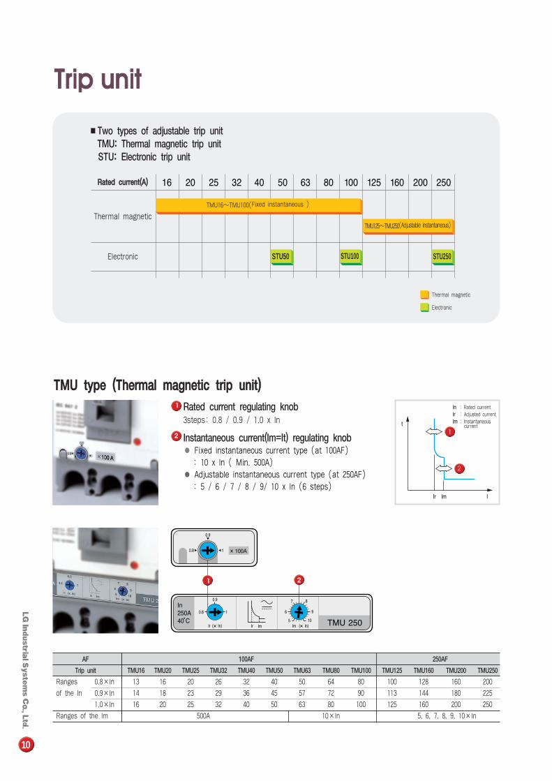
■Two types of adjustable trip unit TMU: Thermal magnetic trip unitSTU: Electronic trip unit
Thermal magnetic
Thermal magnetic
RRaatteedd ccuurrrreenntt((AA))
Electronic
Electronic
TMU16�TMU100(Fixed instantaneous )
TMU125�TMU250(Adjustable instantaneous)
STU250STU100STU50
AF 100AF 250AF
Trip unit TMU16 TMU20 TMU25 TMU32 TMU40 TMU50 TMU63 TMU80 TMU100 TMU125 TMU160 TMU200 TMU250
Ranges 0.8×In 13 16 20 26 32 40 50 64 80 100 128 160 200
of the In 0.9×In 14 18 23 29 36 45 57 72 90 113 144 180 225
1.0×In 16 20 25 32 40 50 63 80 100 125 160 200 250
Ranges of the Im 500A 10×In 5, 6, 7, 8, 9, 10×In
Rated current regulating knob3steps: 0.8 / 0.9 / 1.0 x In
Instantaneous current(Im=It) regulating knob● Fixed instantaneous current type (at 100AF)
: 10 x In ( Min. 500A)● Adjustable instantaneous current type (at 250AF)
: 5 / 6 / 7 / 8 / 9/ 10 x In (6 steps)
TTMMUU ttyyppee ((TThheerrmmaall mmaaggnneettiicc ttrriipp uunniitt))
1
2
IInn : Rated currentIIrr : Adjusted currentIImm : Instantaneous
current
10
TTrriipp uunniitt
11
22
11 22
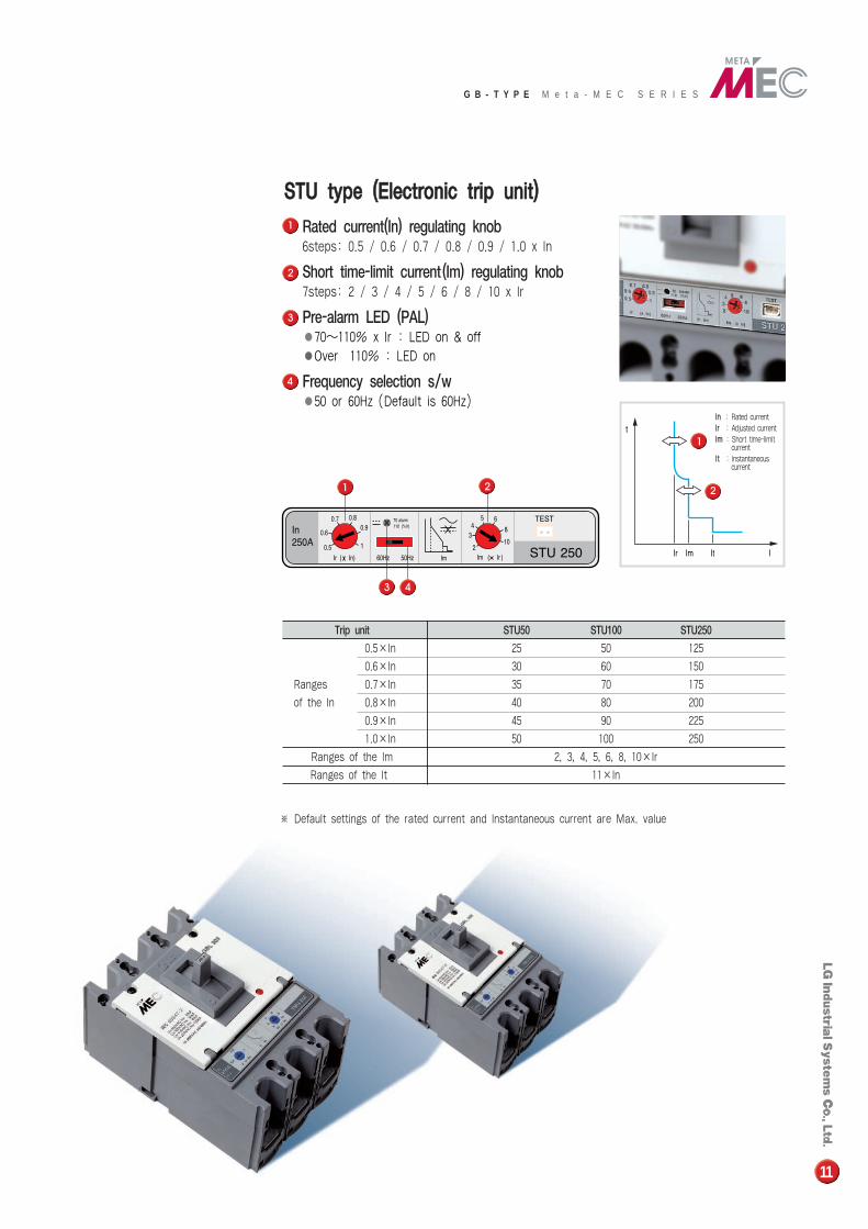
Rated current(In) regulating knob6steps: 0.5 / 0.6 / 0.7 / 0.8 / 0.9 / 1.0 x In
Short time-limit current(Im) regulating knob7steps: 2 / 3 / 4 / 5 / 6 / 8 / 10 x Ir
Pre-alarm LED (PAL)●70�110% x Ir : LED on & off●Over 110% : LED on
Frequency selection s/w●50 or 60Hz (Default is 60Hz)
SSTTUU ttyyppee ((EElleeccttrroonniicc ttrriipp uunniitt))
Trip unit STU50 STU100 STU250
0.5×In 25 50 125
0.6×In 30 60 150
Ranges 0.7×In 35 70 175
of the In 0.8×In 40 80 200
0.9×In 45 90 225
1.0×In 50 100 250
Ranges of the Im 2, 3, 4, 5, 6, 8, 10×Ir
Ranges of the It 11×In
1
1
2
2
IInn : Rated currentIIrr : Adjusted currentIImm : Short time-limit
currentIItt : Instantaneous
current
3 4
1 2
11
4
3
※ Default settings of the rated current and Instantaneous current are Max. value
G B - T Y P E M e t a - M E C S E R I E S
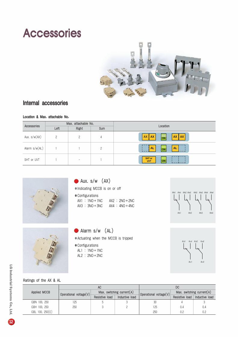
RRaattiinnggss ooff tthhee AAXX && AALL
AAuuxx.. ss//ww ((AAXX))
●Indicating MCCB is on or off
●ConfigurationsAX1 : 1NO+1NC AX2 : 2NO+2NC AX3 : 3NO+3NC AX4 : 4NO+4NC
AXb1
AXc1
AXb2
AXc2
AXa1 AXa2 AXb3
AXc3
AXb4
AXc4
AXa3 AXa4
AAllaarrmm ss//ww ((AALL))
●Actuating when the MCCB is tripped
●ConfigurationsAL1 : 1NO+1NC AL2 : 2NO+2NC
ALb1
ALc1
ALb2
ALc2
ALa1 ALa2
AACC
AApppplliieedd MMCCCCBBOOppeerraattiioonnaall vvoollttaaggee((VV))
MMaaxx.. sswwiittcchhiinngg ccuurrrreenntt((AA))
RReessiissttiivvee llooaadd IInndduuccttiivvee llooaadd
GBN 100, 250 125 5 3
GBH 100, 250 250 3 2
GBL 100, 250(E)
DDCC
OOppeerraattiioonnaall vvoollttaaggee((VV))MMaaxx.. sswwiittcchhiinngg ccuurrrreenntt((AA))
RReessiissttiivvee llooaadd IInndduuccttiivvee llooaadd
30 4 3
125 0.4 0.4
250 0.2 0.2
AAcccceessssoorriieessMMaaxx.. aattttaacchhaabbllee NNoo..
LLooccaattiioonnLLeefftt RRiigghhtt SSuumm
Aux. s/w(AX) 2 2 4
Alarm s/w(AL) 1 1 2
SHT or UVT 1 - 1
AX AX ON AX AX
AL ON AL
SHT orUVT ON
12
AAcccceessssoorriieess
IInntteerrnnaall aacccceessssoorriieess
LLooccaattiioonn && MMaaxx.. aattttaacchhaabbllee NNoo..
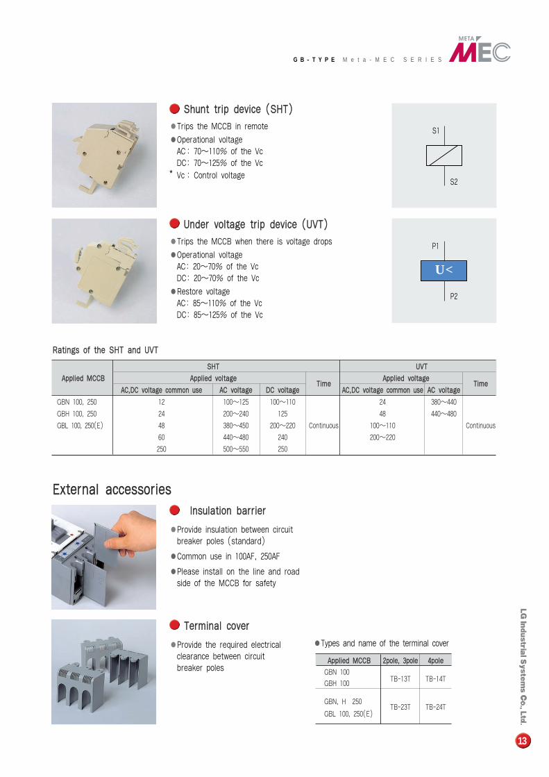
SShhuunntt ttrriipp ddeevviiccee ((SSHHTT))
●Trips the MCCB in remote
●Operational voltage AC: 70�110% of the Vc DC: 70�125% of the Vc
* Vc : Control voltage
UUnnddeerr vvoollttaaggee ttrriipp ddeevviiccee ((UUVVTT))
●Trips the MCCB when there is voltage drops
●Operational voltageAC: 20�70% of the VcDC: 20�70% of the Vc
●Restore voltage AC: 85�110% of the VcDC: 85�125% of the Vc
S1
S2
P1
P2
U <
RRaattiinnggss ooff tthhee SSHHTT aanndd UUVVTT
IInnssuullaattiioonn bbaarrrriieerr
●Provide insulation between circuit breaker poles (standard)
●Common use in 100AF, 250AF
●Please install on the line and road side of the MCCB for safety
TTeerrmmiinnaall ccoovveerr
●Provide the required electrical clearance between circuit breaker poles
SSHHTT UUVVTT
AApppplliieedd MMCCCCBB AApppplliieedd vvoollttaaggeeTTiimmee
AApppplliieedd vvoollttaaggeeTTiimmee
AACC,,DDCC vvoollttaaggee ccoommmmoonn uussee AACC vvoollttaaggee DDCC vvoollttaaggee AACC,,DDCC vvoollttaaggee ccoommmmoonn uussee AACC vvoollttaaggee
GBN 100, 250 12 100�125 100�110 24 380�440
GBH 100, 250 24 200�240 125 48 440�480
GBL 100, 250(E) 48 380�450 200�220 Continuous 100�110 Continuous
60 440�480 240 200�220
250 500�550 250
●Types and name of the terminal cover
AApppplliieedd MMCCCCBB 22ppoollee,, 33ppoollee 44ppoollee
GBN 100TB-13T TB-14T
GBH 100
GBN, H 250
GBL 100, 250(E)TB-23T TB-24T
EExxtteerrnnaall aacccceessssoorriieess
13
G B - T Y P E M e t a - M E C S E R I E S
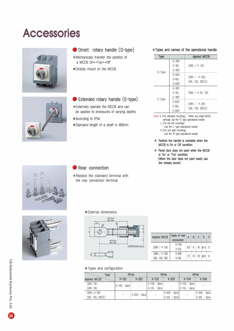
EExxtteennddeedd rroottaarryy hhaannddllee ((EE--ttyyppee))
●Externally operate the MCCB and can be applied to enclosures of varying depths
●According to IP54
●Standard length of a shaft is 469mm
DDiirreecctt rroottaarryy hhaannddllee ((DD--ttyyppee))
●Mechanically transfer the position of a MCCB On↔Trip↔Off
●Directly mount on the MCCB
RReeaarr ccoonnnneeccttiioonn
●Replace the standard terminal with the rear connection terminal
●External dimensions
●●TTyyppeess aanndd nnaammeess ooff tthhee ooppeerraattiioonnaall hhaannddllee
※※ PPaaddlloocckk tthhee hhaannddllee iiss aavvaaiillaabbllee wwhheenn tthhee MMCCCCBB iiss OOnn oorr OOffff ccoonnddiittiioonn
※※ PPaanneell ddoooorr ddooeess nnoott ooppeenn wwhheenn tthhee MMCCCCBB iiss ''OOnn'' oorr ''TTrriipp'' ccoonnddiittiioonn((WWhheenn tthhee ddoooorr ddooeess nnoott ooppeenn eeaassiillyy uussee tthhee rreelleeaassee ssccrreeww))
TTyyppee AApppplliieedd MMCCCCBB
D-30S
D-30L GBN / H 100
D-TypeD-30R
D-60SGBN / H 250
D-60LGBL 100, 250(E)
D-60R
E-30S
E-30L GBN / H 50, 100
E-TypeE-30R
E-60SGBN / H 250
E-60LGBL 100, 250(E)
E-60R
Note) S (For standard mounting) : When you install MCCB vertically use the 'S 'type operational handle
L (For line left mounting) : Use the 'L' type operational handle
R (For line right mounting) : Use the 'R' type operational handle
●Types and configuration
22PPoollee 33PPoollee 44PPoollee
XX--110022 XX--220022 XX--110033 XX--220033 XX--110044 XX--220044
GBN 100X-10S : 4pcs -
X-10S : 4pcs-
X-10S : 4pcs-
GBH 100 X-10L : 2pcs X-10L : 4pcs
GBN, H 250- X-20S : 4pcs
X-20S : 4pcs-
X-20S : 4pcs
GBL 100, 250(E)-
X-20L : 2pcs X-20L : 4pcs
GBN / H 100X-10S
63 8 16 5X-10L
GBN / H 250 X-20S72 12 18 6
GBL 100, 250 X-20L
AApppplliieedd MMCCCCBB TTyyppeess ooff rreeaarr AA BB CC DD EEccoonnnneeccttiioonn
ф14
ф20
AApppplliieedd MMCCCCBB
TTyyppee
14
AAcccceessssoorriieess
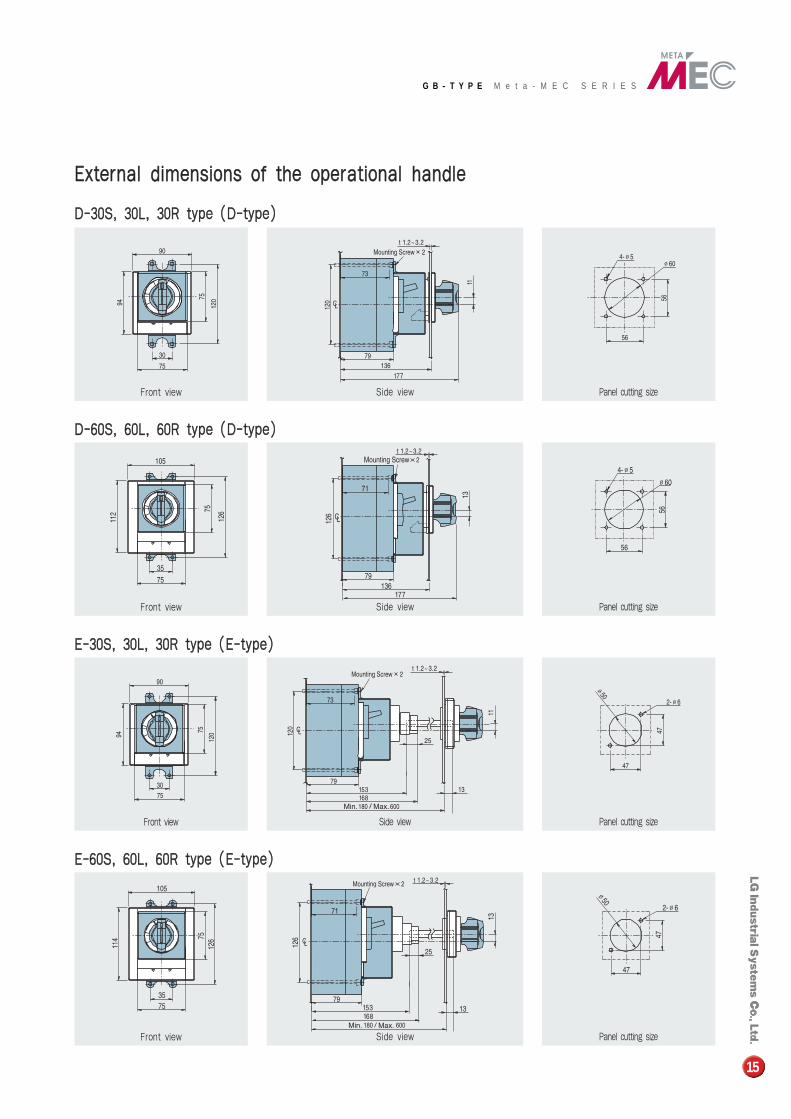
Front view Side view Panel cutting size
Front view Side view Panel cutting size
Front view Side view Panel cutting size
Front view Side view Panel cutting size
DD--3300SS,, 3300LL,, 3300RR ttyyppee ((DD--ttyyppee))
DD--6600SS,, 6600LL,, 6600RR ttyyppee ((DD--ttyyppee))
EE--3300SS,, 3300LL,, 3300RR ttyyppee ((EE--ttyyppee))
EE--6600SS,, 6600LL,, 6600RR ttyyppee ((EE--ttyyppee))
EExxtteerrnnaall ddiimmeennssiioonnss ooff tthhee ooppeerraattiioonnaall hhaannddllee
15
G B - T Y P E M e t a - M E C S E R I E S
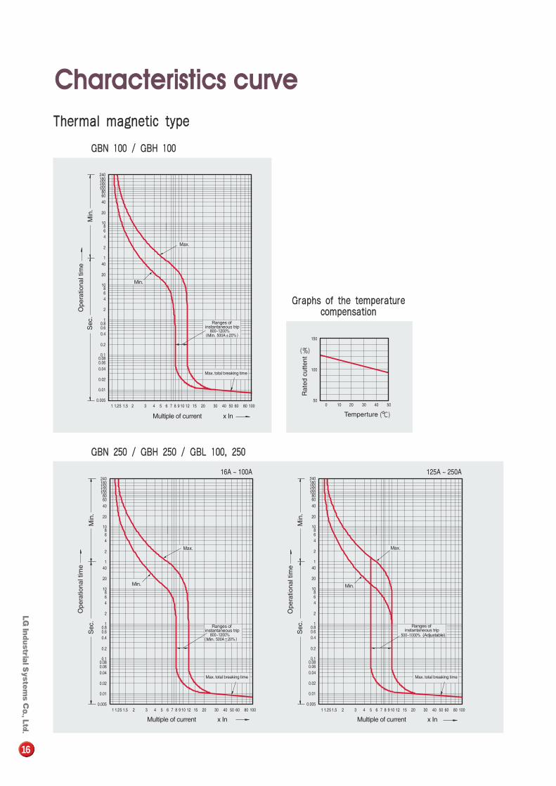
TThheerrmmaall mmaaggnneettiicc ttyyppee
GGBBNN 110000 // GGBBHH 110000
GGBBNN 225500 // GGBBHH 225500 // GGBBLL 110000,, 225500
GGrraapphhss ooff tthhee tteemmppeerraattuurreeccoommppeennssaattiioonn
16
CChhaarraacctteerriissttiiccss ccuurrvvee
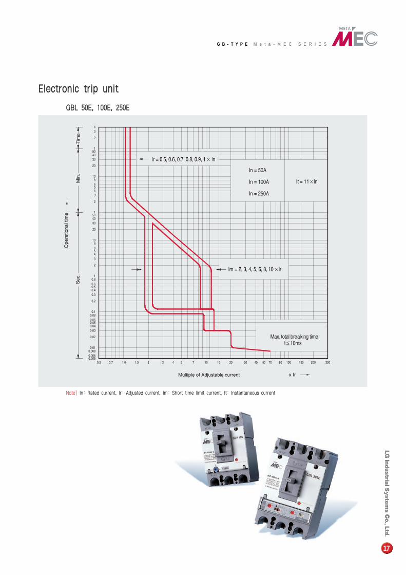
EElleeccttrroonniicc ttrriipp uunniitt
GGBBLL 5500EE,, 110000EE,, 225500EE
�Note) In: Rated current, Ir: Adjusted current, Im: Short time limit current, It: Instantaneous current
17
G B - T Y P E M e t a - M E C S E R I E S
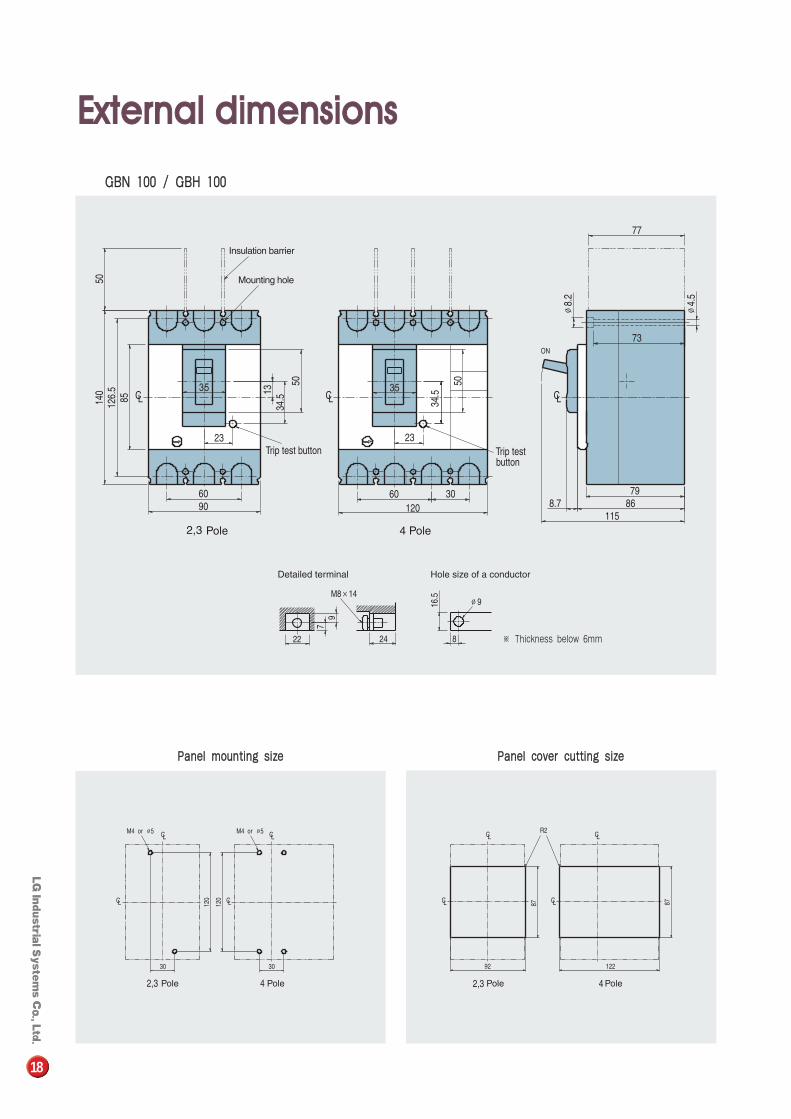
GGBBNN 110000 // GGBBHH 110000
PPaanneell mmoouunnttiinngg ssiizzee PPaanneell ccoovveerr ccuuttttiinngg ssiizzee
※ Thickness below 6mm
18
EExxtteerrnnaall ddiimmeennssiioonnss
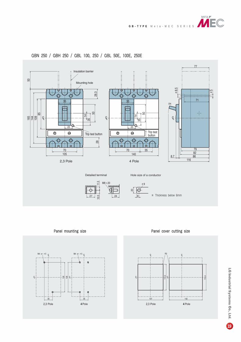
GGBBNN 225500 // GGBBHH 225500 // GGBBLL 110000,, 225500 // GGBBLL 5500EE,, 110000EE,, 225500EE
PPaanneell mmoouunnttiinngg ssiizzee PPaanneell ccoovveerr ccuuttttiinngg ssiizzee
※ Thickness below 6mm
19
G B - T Y P E M e t a - M E C S E R I E S
LG constantly endeavors to improveour products, so that information in
this catalog is subject to change without notice.
MCCB Adj.-99.9901/Dec. 1999 Printed in Korea STAFF