Embed Size (px)
Citation preview

11890104
Safety when servicing
Operating instructions
Other controls
Table of contents
OPERATOR'S MANUAL
Presentation
Instrument panels
Operating techniques
Service and maintenance
Specifications
Alphabetical index
ForewordThis Operator's Manual is intended as a guide for the correct use and maintenance of the machine. Therefore, study it carefully before starting and operating the machine, or before carrying out any preventive maintenance.
Keep the manual in the cab so that it is always at hand. Re-place it immediately, if it is lost.
The manual describes the applications for which the machine primarily is intended and is written to apply for all markets. We therefore ask you to disregard the sections which are not ap-plicable to your machine or to the work for which you use your machine.
NOTE: The information in the manual applies to both ma-chine types, TH60 and TH80, unless otherwise stated.
Many hours are spent on design and production to make a machine that is as efficient and safe as possible. The acci-dents which occur in spite of this, are mostly caused by the human factor. A safety conscious person and a well main-tained machine make a safe, efficient and profitable combina-tion. Therefore, read the safety instructions and follow them.
We continually strive to improve our products and to make them more efficient through changes to their design. We re-tain the right to this without committing ourselves to introduc-ing these improvements on products, which have already been delivered. We also retain the right to change data and equipment, as well as instructions for service and other main-tenance measures without prior notice.
Safety regulationsIt is the operator's obligation to know and follow the applica-ble national and local safety regulations. The safety instruc-tions in this manual only apply to cases when there are no national or local regulations.
Get to know the capacity and limits of your machine!
WARNING!The symbol above appears at various points in the manual together with a warning text. It means:Warning, be alert! Your safety is involved! It is the obli-gation of the operator to make sure that all warning decals are in place on the machine and that they are readable. Accidents may otherwise occur.

Foreword
2 Identification numbers
Identification numbersState the identification number of the machine and the components below. The number should be stated when contacting the manufacturer and when ordering spare parts. The plates are described on page 8.
ManufacturerMEC Aerial Platform Sales Corp 1775 Park Street, Suite 77 Selma, CA 93662USA
PIN (Serial No.)
Engine
Transmission
Drop box
Front axle
Rear axle
Cab/Open ROPS

Table of contents
3
Table of contentsForeword....................................................................1
Identification numbers ............................................................ 2
Table of contents ......................................................3
Presentation ..............................................................5Machine view.......................................................................... 7Product plates......................................................................... 8Information and warning decals.............................................. 9The USA Federal Clean Air Act............................................ 14
Instrument panels ...................................................17Left instrument panel ............................................................ 18Center instrument panel ....................................................... 20Right instrument panel.......................................................... 26
Other controls .........................................................29Controls ................................................................................ 29Operator comfort .................................................................. 34
Operating instructions ...........................................35Safety rules when operating ................................................. 36Center of gravity ................................................................... 40Measures before operating................................................... 42Starting engine ..................................................................... 43Steering ................................................................................ 45Leveling the machine frame ................................................. 47Gear shifting ......................................................................... 48Braking ................................................................................. 49Stopping the machine........................................................... 50Parking ................................................................................. 51Towing .................................................................................. 52Boom, manual lowering ........................................................ 55Transporting the machine..................................................... 56
Operating techniques .............................................57Attachments.......................................................................... 58Pallet forks............................................................................ 61Accumulator.......................................................................... 64Hydraulic couplings .............................................................. 65Off-road operation ................................................................ 66Signalling diagram ................................................................ 67
Safety when servicing ............................................69Service positions .................................................................. 69Before service read .............................................................. 72
Service and maintenance.......................................79Service points ....................................................................... 80Engine .................................................................................. 81Fuel system .......................................................................... 83Turbocharger ........................................................................ 86Air cleaner ............................................................................ 87Cooling system..................................................................... 88Electrical system................................................................... 91Transmission ........................................................................ 94Drop box ............................................................................... 96Axles..................................................................................... 97Brake system...................................................................... 100Boom .................................................................................. 101

Table of contents
4
Tires.................................................................................... 103Cab/Open ROPS................................................................ 104Hydraulic system ................................................................ 105Attachments, maintenance ................................................. 107Lubrication and service chart.............................................. 109Lubrication points ............................................................... 114
Specifications........................................................117Recommended lubricants................................................... 117Service capacities and lubricants ....................................... 119Engine, specifications......................................................... 120Electrical system, specifications ......................................... 121Transmission, specifications............................................... 125Axle, hubs, transmission and dropbox oils ......................... 126Axles, specifications ........................................................... 128Brakes/steering system, specifications .............................. 129Tire combination chart, specifications ................................ 130Cab/Open ROPS, specifications ........................................ 131Hydraulic system, specifications......................................... 132Machine capacity................................................................ 133Dimensional drawing .......................................................... 139
Alphabetical index ................................................141
Presentation
5
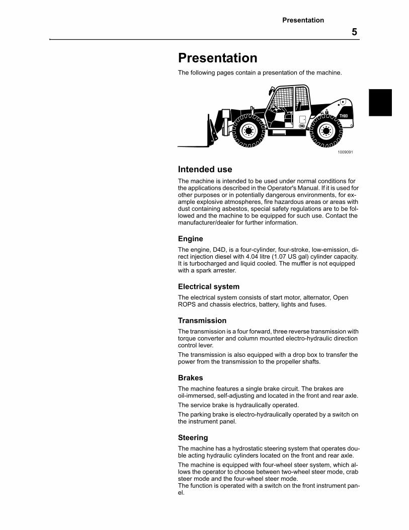
PresentationThe following pages contain a presentation of the machine.
Intended useThe machine is intended to be used under normal conditions for the applications described in the Operator's Manual. If it is used for other purposes or in potentially dangerous environments, for ex-ample explosive atmospheres, fire hazardous areas or areas with dust containing asbestos, special safety regulations are to be fol-lowed and the machine to be equipped for such use. Contact the manufacturer/dealer for further information.
EngineThe engine, D4D, is a four-cylinder, four-stroke, low-emission, di-rect injection diesel with 4.04 litre (1.07 US gal) cylinder capacity. It is turbocharged and liquid cooled. The muffler is not equipped with a spark arrester.
Electrical systemThe electrical system consists of start motor, alternator, Open ROPS and chassis electrics, battery, lights and fuses.
TransmissionThe transmission is a four forward, three reverse transmission with torque converter and column mounted electro-hydraulic direction control lever.
The transmission is also equipped with a drop box to transfer the power from the transmission to the propeller shafts.
BrakesThe machine features a single brake circuit. The brakes are oil-immersed, self-adjusting and located in the front and rear axle.
The service brake is hydraulically operated.
The parking brake is electro-hydraulically operated by a switch on the instrument panel.
SteeringThe machine has a hydrostatic steering system that operates dou-ble acting hydraulic cylinders located on the front and rear axle.
The machine is equipped with four-wheel steer system, which al-lows the operator to choose between two-wheel steer mode, crab steer mode and the four-wheel steer mode.The function is operated with a switch on the front instrument pan-el.
1009091
Presentation
6
Cab/Open ROPS
The machine is available with two different types of cabs. The Open ROPS is an open cab without door or windows. The cab is an enclosed cab with door and windows. Both types incorporate a full FOPS and ROPS structure with full instrumentation, ergonomic hand control for the boom and tilt movements, control for machine angularity, and vinyl seat.
FOPS and ROPS
The cab is approved as a protective cab according to FOPS and ROPS standards, see page 131. FOPS is an abbreviation of Fall-ing Object Protective Structure (roof protection) and ROPS is an abbreviation of Roll Over Protective Structure (roll over protection).
Never carry out any unauthorised alterations to the cab, e.g. low-ering the roof height, drilling, welding on brackets for fire extin-guisher, radio aerial or other equipment, without first having discussed the alteration with personnel at the MEC Engineering Department. This department will decide whether the alteration causes the FOPS and ROPS approval to become void.
It is important that all parties concerned are aware of these regu-lations.
Axles
The axles provide full time four-wheel drive. The axles features spiral crown and pinion driving through epicyclic hubs and inboard oil immersed brakes.
Drive is provided by propeller shafts direct from the transmission/dropbox.
Hydraulic system
The hydraulic system has a fixed gear pump with closed center and a fixed displacement gear pump for boom and fork functions. Functions are controlled through the control valve. The machine can be equipped with extra hydraulic outputs at the front end of the boom for different applications.
Alternator
The alternator drive belt is of self adjusting type.
Equipment
MEC supplies a range of after-market kits and options. Con-tact your MEC dealer for further details.
Presentation
Machine view 7
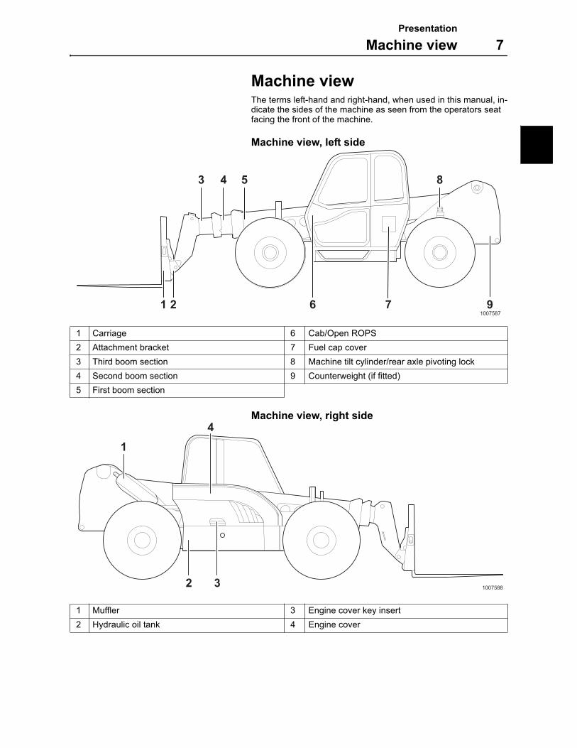
Machine viewThe terms left-hand and right-hand, when used in this manual, in-dicate the sides of the machine as seen from the operators seat facing the front of the machine.
Machine view, left side
Machine view, right side
1 Carriage 6 Cab/Open ROPS
2 Attachment bracket 7 Fuel cap cover
3 Third boom section 8 Machine tilt cylinder/rear axle pivoting lock
4 Second boom section 9 Counterweight (if fitted)
5 First boom section
1 Muffler 3 Engine cover key insert
2 Hydraulic oil tank 4 Engine cover
62
3 4 5 8
1 7 91007587
10075882 3
1
4
Presentation
8 Product plates
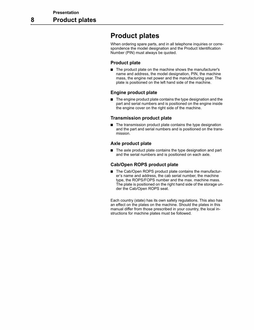
Product platesWhen ordering spare parts, and in all telephone inquiries or corre-spondence the model designation and the Product Identification Number (PIN) must always be quoted.
Product plate
The product plate on the machine shows the manufacturer's name and address, the model designation, PIN, the machine mass, the engine net power and the manufacturing year. The plate is positioned on the left hand side of the machine.
Engine product plate
The engine product plate contains the type designation and the part and serial numbers and is positioned on the engine inside the engine cover on the right side of the machine.
Transmission product plate
The transmission product plate contains the type designation and the part and serial numbers and is positioned on the trans-mission.
Axle product plate
The axle product plate contains the type designation and part and the serial numbers and is positioned on each axle.
Cab/Open ROPS product plate
The Cab/Open ROPS product plate contains the manufactur-er’s name and address, the cab serial number, the machine type, the ROPS/FOPS number and the max. machine mass. The plate is positioned on the right hand side of the storage un-der the Cab/Open ROPS seat.
Each country (state) has its own safety regulations. This also has an effect on the plates on the machine. Should the plates in this manual differ from those prescribed in your country, the local in-structions for machine plates must be followed.
Presentation
Information and warning decals 9
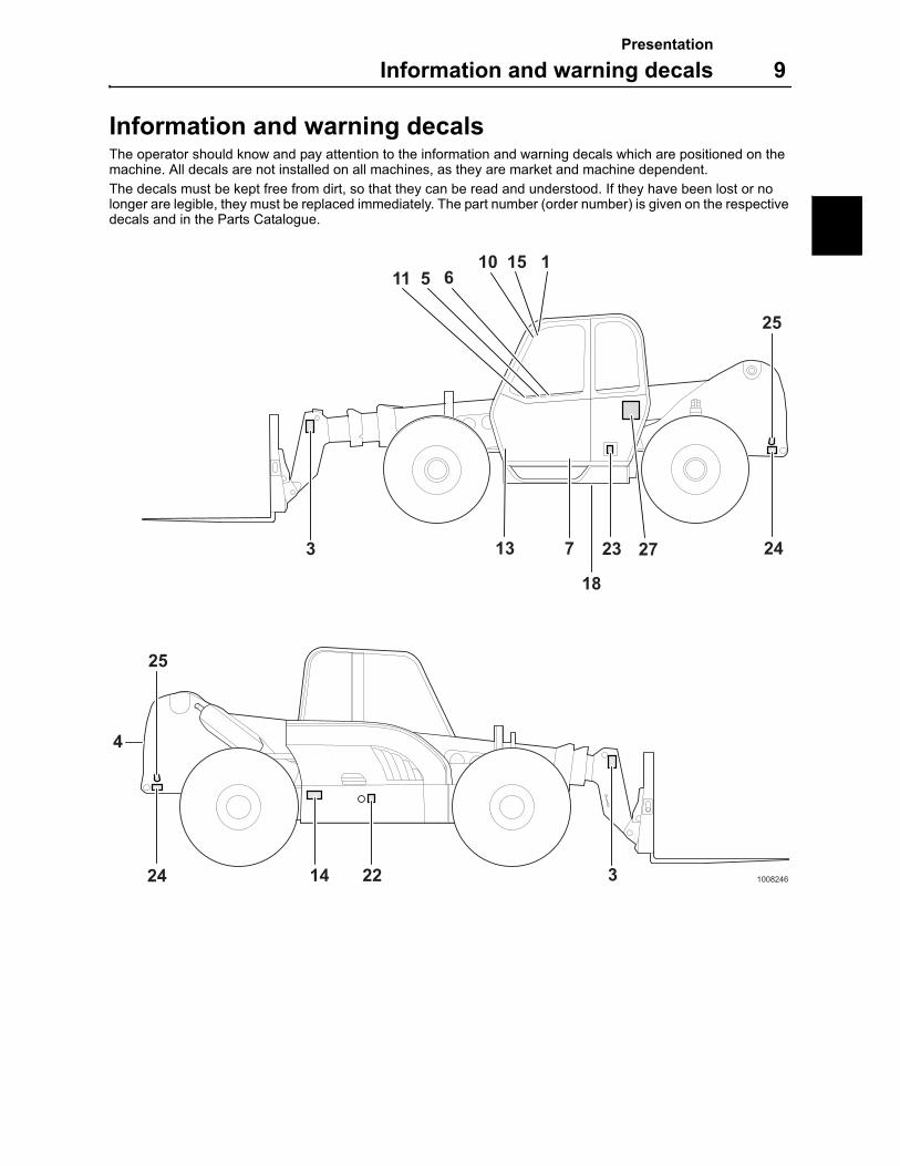
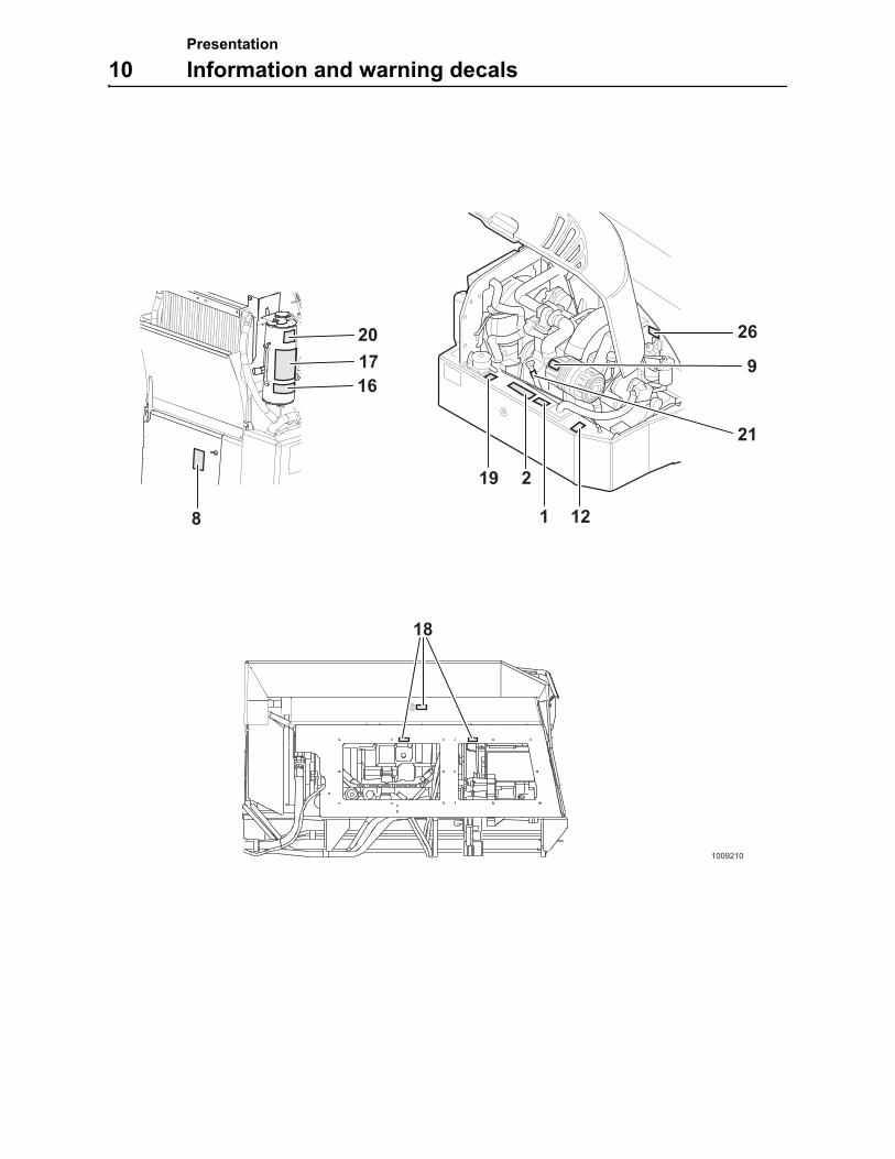
Information and warning decalsThe operator should know and pay attention to the information and warning decals which are positioned on the machine. All decals are not installed on all machines, as they are market and machine dependent.
The decals must be kept free from dirt, so that they can be read and understood. If they have been lost or no longer are legible, they must be replaced immediately. The part number (order number) is given on the respective decals and in the Parts Catalogue.
7
4
1008246
25
324
25
243 23 2713
2214
15 110
18
5 611
Presentation
10 Information and warning decals
1009210
18
8
201716
19 2
1 12
9
26
21
Presentation
Information and warning decals 11
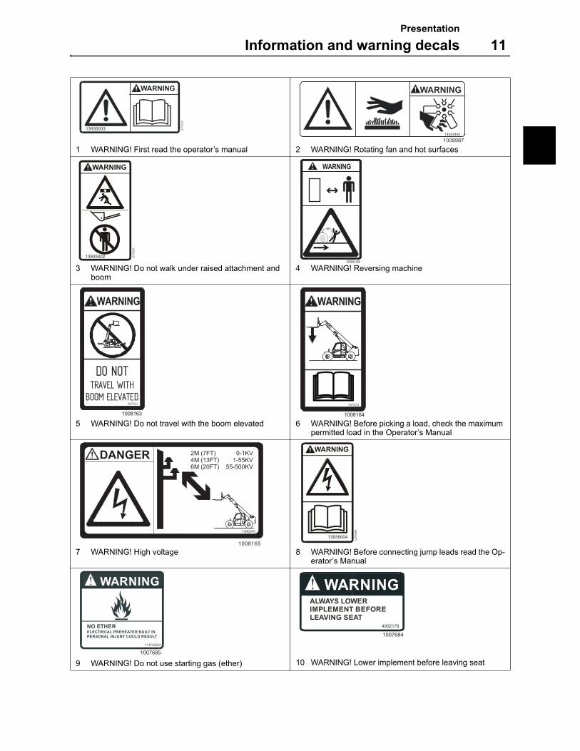
1 WARNING! First read the operator’s manual 2 WARNING! Rotating fan and hot surfaces
3 WARNING! Do not walk under raised attachment and boom
4 WARNING! Reversing machine
5 WARNING! Do not travel with the boom elevated 6 WARNING! Before picking a load, check the maximum permitted load in the Operator’s Manual
7 WARNING! High voltage 8 WARNING! Before connecting jump leads read the Op-erator’s Manual
9 WARNING! Do not use starting gas (ether) 10 WARNING! Lower implement before leaving seat
13935003 L67524A
WARNING
14343404
1008987
13935002 L67528A
WARNING
1008149
DO NOTTRAVEL WITH
BOOM ELEVATED
WARNING
11870562
1008163
WARNING
11870558
1008164
2M (7FT) 0-1KV4M (13FT) 1-55KV6M (20FT) 55-500KV
11862243
1008165
DANGER
13935004
L6
75
35
A
WARNING
NO ETHERELECTRICAL PREHEATER BUILT INPERSONAL INJURY COULD RESULT
11013034
1007685
WARNINGALWAYS LOWERIMPLEMENT BEFORELEAVING SEAT
4952179
1007684
Presentation
12 Information and warning decals
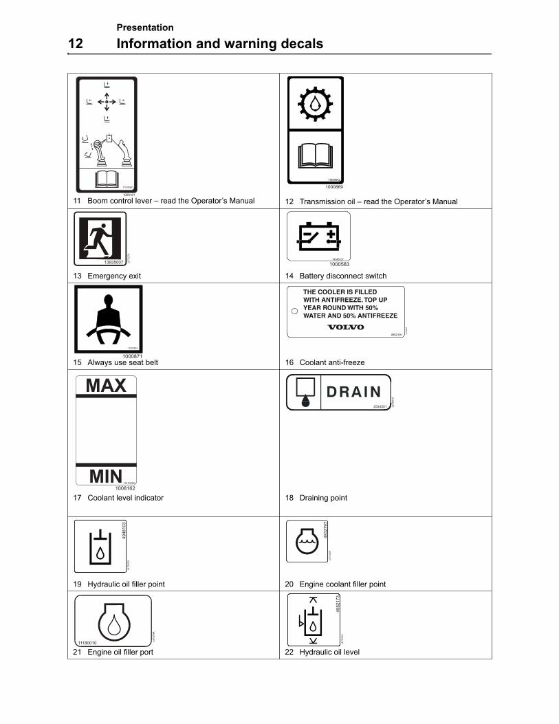
11 Boom control lever – read the Operator’s Manual 12 Transmission oil – read the Operator’s Manual
13 Emergency exit 14 Battery disconnect switch
15 Always use seat belt 16 Coolant anti-freeze
17 Coolant level indicator 18 Draining point
19 Hydraulic oil filler point 20 Engine coolant filler point
21 Engine oil filler port 22 Hydraulic oil level
11870561
1008161
11883642
1000869
13935007 L67527A
14346537
1000583
11883294
1000871
4952181 L67
584A
MAX
MIN11870560
1008162
2534201 L67
60
1A
49
481
03
L67542A
493
2797
L67540A
11180010
L6
75
79
A
495
217
3L67541A
Presentation
Information and warning decals 13
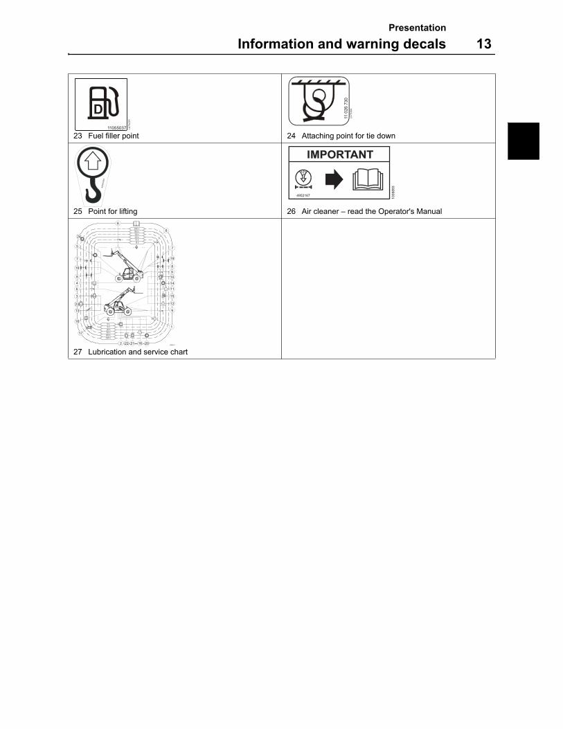
23 Fuel filler point 24 Attaching point for tie down
25 Point for lifting 26 Air cleaner – read the Operator's Manual
27 Lubrication and service chart
D11055037 L6
7543A
110
26
730
L67530A
48
98
49
5
4952167
1008893
10 h
2000 h
500 h1000 h
250 h 50 h
2000 h
250 h 50 h10 h
1000 h500 h
1
6
7
19
8
9
10
14
11
15
12
2122
17
18
13
23
3
4
6
8
19
7
5
24
2016
6
2
9
1008510
Presentation
14 The USA Federal Clean Air Act
The USA Federal Clean Air ActThe Federal Clean Air Act Section 203 (a) (3) prohibits the removal of air pollution control devices or the modification of an EPA-certi-fied non-road engine to a non-certified configuration.
The Federal regulations implementing the Clean Air Act for non-road engines, 40 C.F.R.Section 89.1003(a)(3)(i), reads as follows:
The following act and the causing thereof are prohibited:
For a person to remove or render inoperative a device or ele-ment of design installed on or in a non-road engine vehicle or equipment in compliance with regulations under this part pri-or to its sale and delivery to the ultimate purchaser or for a person knowingly to remove or render inoperative such a de-vice or element of design after the sale and delivery to the ul-timate purchaser.
The law provides a penalty of up to $2,500 for each violation.
An example of a prohibited modification is the recalibration of the fuel system so that the engine will exceed the certified horsepower or torque.
You should not make a change to an EPA-certified non-road en-gine that would result in an engine that does not match the engine configuration certified to meet the Federal Standards.
Customer Assistance
MEC Construction Equipment wishes to help assure that the Emission Control System Warranty is properly administered. In event that you do not receive the warranty service to which you be-lieve you are entitled under the Emission Control System Warran-ty, you should contact your nearest MEC Construction Equipment Regional office for assistance.

Presentation
The USA Federal Clean Air Act 15
Normal Non-Road Engine Use
The Maintenance Instructions are based on the assumption that this conventional machine will be used as designated in the Oper-ator’s Instruction Manual and operated only with the specified fuel and lubrication oils.
Non-Road Engine Maintenance
The non-road engine is of conventional design and any local deal-er may perform the necessary non-road engine emission control maintenance defined in this manual.
MEC recommends that the purchaser use the service program for the non-road engine, known as Preventative Maintenance, includ-ing the recommended engine emission control maintenance.
In order to document that the proper regular maintenance has been performed on the non-road engine, MEC recommends that the owner keep all records and receipts of such maintenance. These records and receipts should be transferred to each subse-quent purchaser of the non-road engine.
Service Performed By Your Local Dealer
Your local dealer is best qualified to give you good, dependable service since he has trained service technicians and is equipped with genuine original manufacturer´s parts and special tools, as well as the latest technical publications. Discuss your servicing and maintenance requirements with your local dealer. He can tailor a maintenance program for your needs.
For regular scheduled service or maintenance, it is advisable to contact your local dealer in advance to arrange for an appointment to ensure availability of the correct equipment and service techni-cian to work on your machine. This will aid your local dealer in ef-forts to decrease service time on your machine.
Preventative Maintenance Program
To retain the dependability, noise level and exhaust emission con-trol performance originally built into your conventional non-road engine, it is essential that the non-road engine receive periodic service, inspections, adjustments and maintenance.
Presentation
16 The USA Federal Clean Air Act
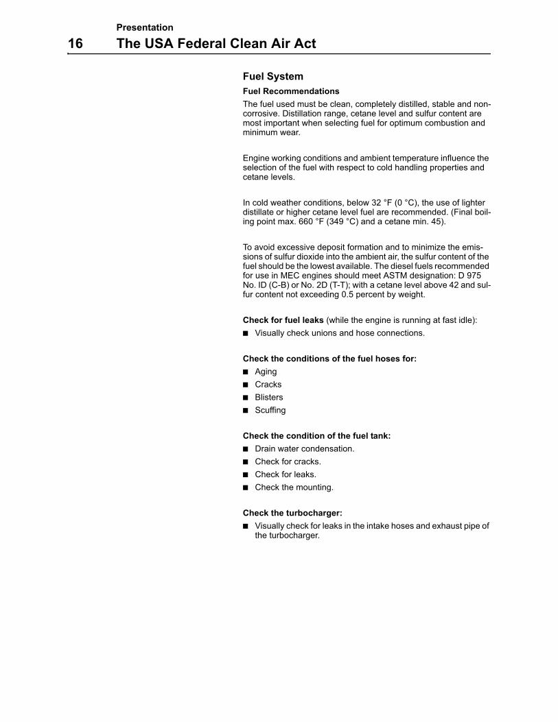
Fuel System
Fuel Recommendations
The fuel used must be clean, completely distilled, stable and non-corrosive. Distillation range, cetane level and sulfur content are most important when selecting fuel for optimum combustion and minimum wear.
Engine working conditions and ambient temperature influence the selection of the fuel with respect to cold handling properties and cetane levels.
In cold weather conditions, below 32 °F (0 °C), the use of lighter distillate or higher cetane level fuel are recommended. (Final boil-ing point max. 660 °F (349 °C) and a cetane min. 45).
To avoid excessive deposit formation and to minimize the emis-sions of sulfur dioxide into the ambient air, the sulfur content of the fuel should be the lowest available. The diesel fuels recommended for use in MEC engines should meet ASTM designation: D 975 No. ID (C-B) or No. 2D (T-T); with a cetane level above 42 and sul-fur content not exceeding 0.5 percent by weight.
Check for fuel leaks (while the engine is running at fast idle):
Visually check unions and hose connections.
Check the conditions of the fuel hoses for:
Aging
Cracks
Blisters
Scuffing
Check the condition of the fuel tank:
Drain water condensation.
Check for cracks.
Check for leaks.
Check the mounting.
Check the turbocharger:
Visually check for leaks in the intake hoses and exhaust pipe of the turbocharger.
Instrument panels
17
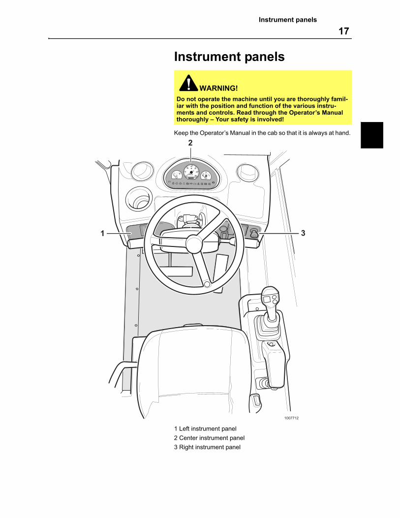
Instrument panels
Keep the Operator’s Manual in the cab so that it is always at hand.
1 Left instrument panel
2 Center instrument panel
3 Right instrument panel
WARNING!
Do not operate the machine until you are thoroughly famil-iar with the position and function of the various instru-ments and controls. Read through the Operator’s Manual thoroughly – Your safety is involved!
1007712
1 3
2
1/2
0
Instrument panels
18 Left instrument panel
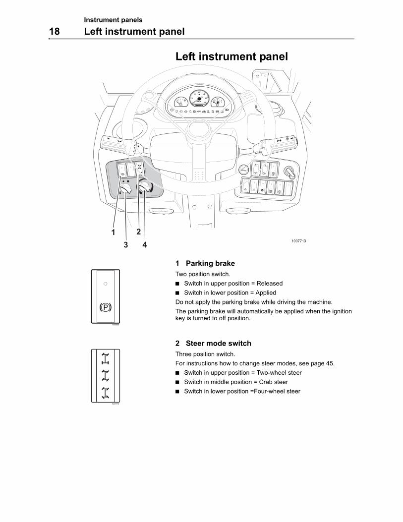
Left instrument panel
1 Parking brake
Two position switch.
Switch in upper position = Released
Switch in lower position = Applied
Do not apply the parking brake while driving the machine.
The parking brake will automatically be applied when the ignition key is turned to off position.
2 Steer mode switch
Three position switch.
For instructions how to change steer modes, see page 45.
Switch in upper position = Two-wheel steer
Switch in middle position = Crab steer
Switch in lower position =Four-wheel steer
1/2
0
023
4
1
10077133 41 2
1000896
1007770
Instrument panels
Left instrument panel 19
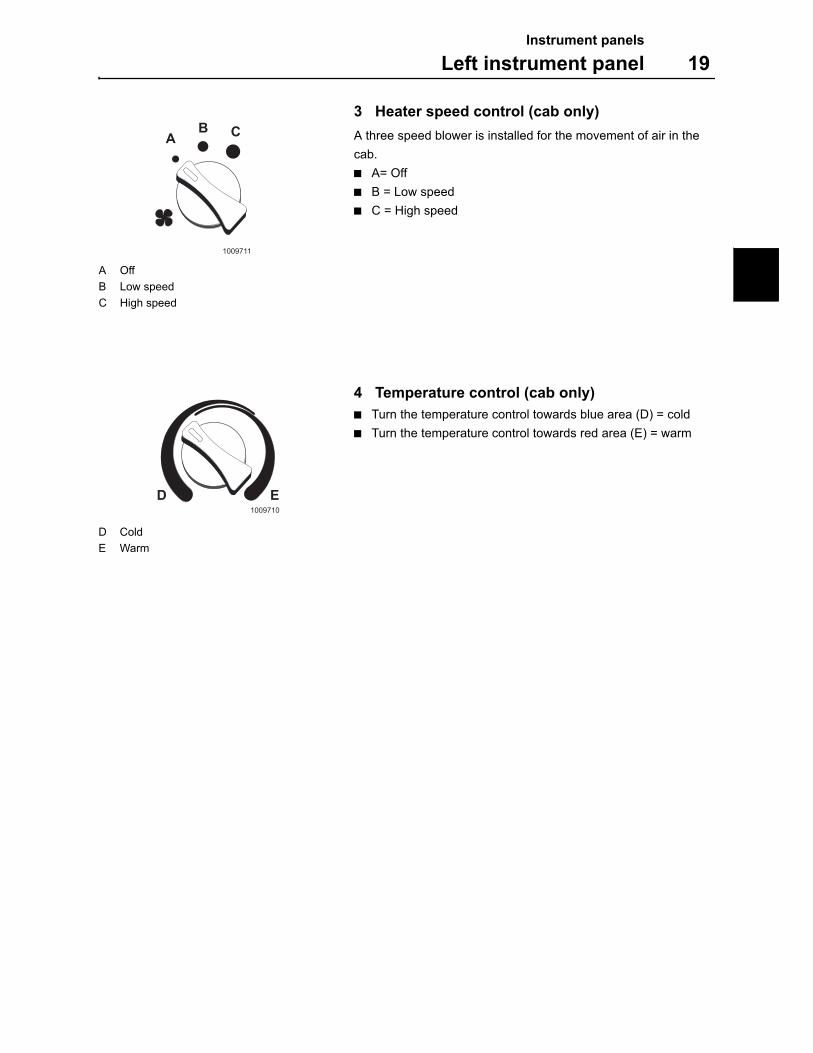
3 Heater speed control (cab only)
A three speed blower is installed for the movement of air in the
cab.
A= Off
B = Low speed
C = High speed
4 Temperature control (cab only)
Turn the temperature control towards blue area (D) = cold
Turn the temperature control towards red area (E) = warm
1009711
AB C
A Off
B Low speed
C High speed
1009710
D E
D Cold
E Warm
Instrument panels
20 Center instrument panel
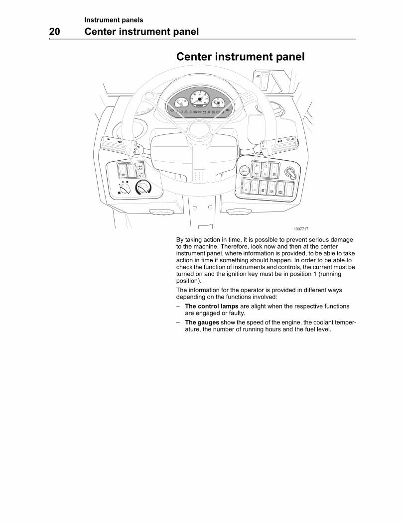
Center instrument panel
By taking action in time, it is possible to prevent serious damage to the machine. Therefore, look now and then at the center instrument panel, where information is provided, to be able to take action in time if something should happen. In order to be able to check the function of instruments and controls, the current must be turned on and the ignition key must be in position 1 (running position).
The information for the operator is provided in different ways depending on the functions involved:
– The control lamps are alight when the respective functions are engaged or faulty.
– The gauges show the speed of the engine, the coolant temper-ature, the number of running hours and the fuel level.
1/2
0
023
4
1
1007717
Instrument panels
Center instrument panel 21
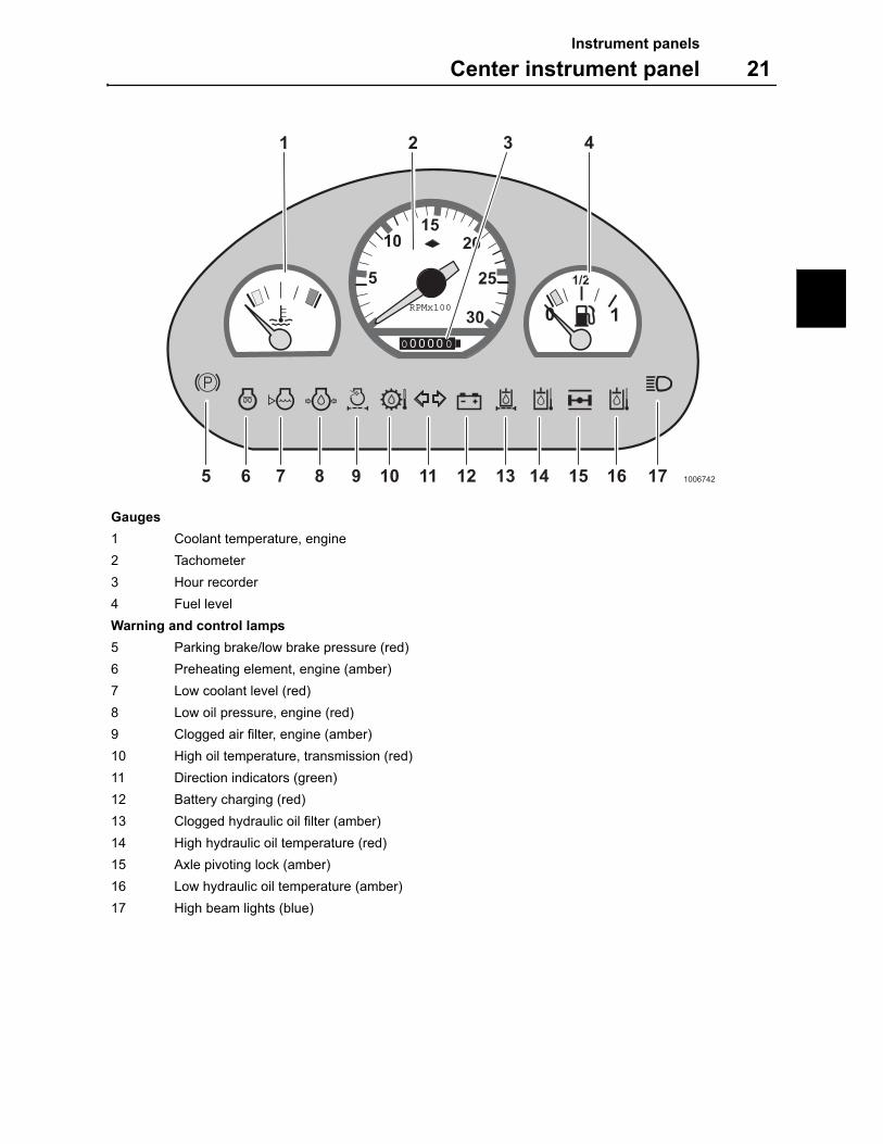
Gauges
1 Coolant temperature, engine
2 Tachometer
3 Hour recorder
4 Fuel level
Warning and control lamps
5 Parking brake/low brake pressure (red)
6 Preheating element, engine (amber)
7 Low coolant level (red)
8 Low oil pressure, engine (red)
9 Clogged air filter, engine (amber)
10 High oil temperature, transmission (red)
11 Direction indicators (green)
12 Battery charging (red)
13 Clogged hydraulic oil filter (amber)
14 High hydraulic oil temperature (red)
15 Axle pivoting lock (amber)
16 Low hydraulic oil temperature (amber)
17 High beam lights (blue)
km/h
000000
10
20
3040
60
50
0 0
RPMx100
1/2
0
2 3
6 875 9 10 11 12 13 14 15 16 17 1006742
41
Instrument panels
22 Center instrument panel
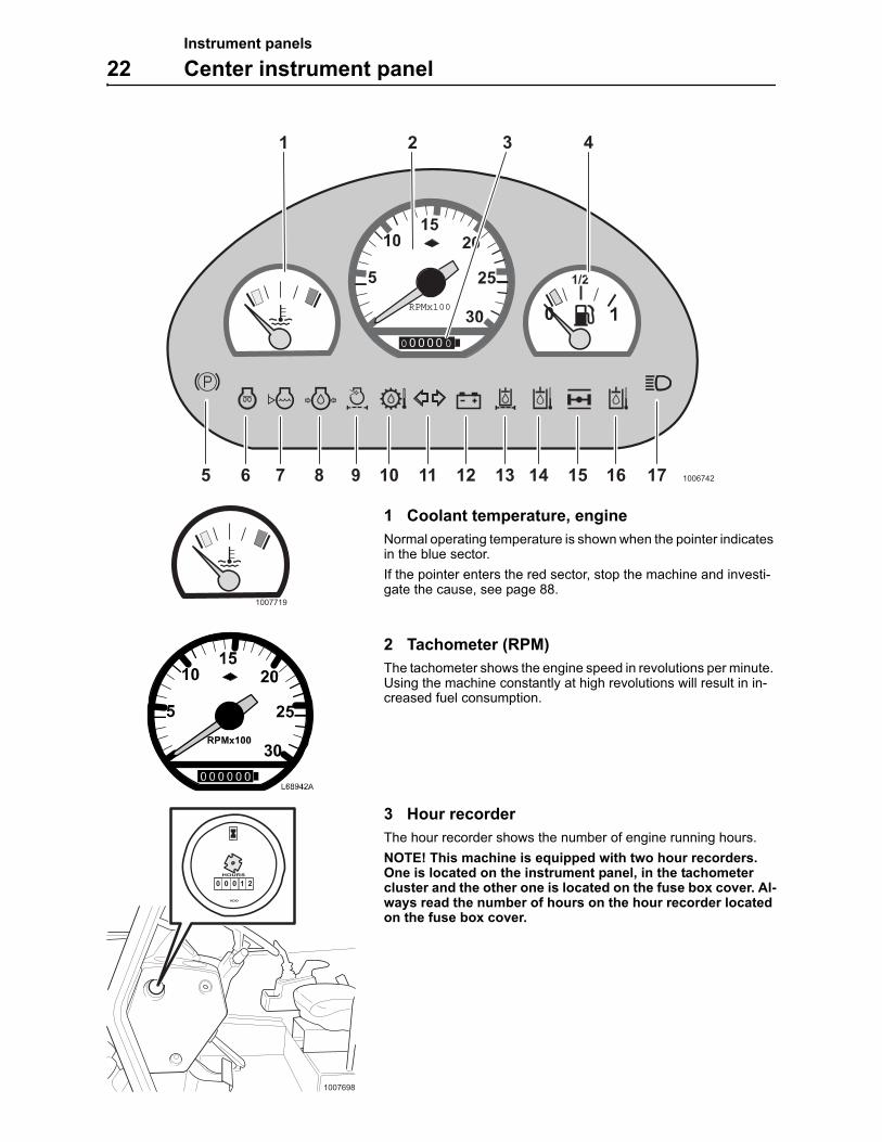
1 Coolant temperature, engine
Normal operating temperature is shown when the pointer indicates in the blue sector.
If the pointer enters the red sector, stop the machine and investi-gate the cause, see page 88.
2 Tachometer (RPM)
The tachometer shows the engine speed in revolutions per minute. Using the machine constantly at high revolutions will result in in-creased fuel consumption.
3 Hour recorder
The hour recorder shows the number of engine running hours.
NOTE! This machine is equipped with two hour recorders. One is located on the instrument panel, in the tachometer cluster and the other one is located on the fuse box cover. Al-ways read the number of hours on the hour recorder located on the fuse box cover.
km/h
000000
10
20
3040
60
50
0 0
RPMx100
1/2
0
2 3
6 875 9 10 11 12 13 14 15 16 17 1006742
41
1007719
km/h
0 0 0 00 0
10
20
3040
60
50
1007698
VDO
HOURS
0 0 0 1 2
Instrument panels
Center instrument panel 23
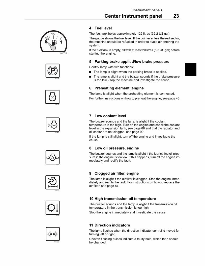
4 Fuel level
The fuel tank holds approximately 122 litres (32.2 US gal).
The gauge shows the fuel level. If the pointer enters the red sector, the machine should be refuelled in order to avoid air entering the system.
If the fuel tank is empty, fill with at least 20 litres (5.3 US gal) before starting the engine.
5 Parking brake applied/low brake pressure
Control lamp with two functions:
The lamp is alight when the parking brake is applied.
The lamp is alight and the buzzer sounds if the brake pressure is too low. Stop the machine and investigate the cause.
6 Preheating element, engine
The lamp is alight when the preheating element is connected.
For further instructions on how to preheat the engine, see page 43.
7 Low coolant level
The buzzer sounds and the lamp is alight if the coolant temperature is too high. Turn off the engine and check the coolant level in the expansion tank, see page 88 and that the radiator and oil cooler are not clogged, see page 90.
If the lamp is still alight, turn off the engine and investigate the cause.
8 Low oil pressure, engine
The buzzer sounds and the lamp is alight if the lubricating oil pres-sure in the engine is too low. If this happens, turn off the engine im-mediately and rectify the fault.
9 Clogged air filter, engine
The lamp is alight if the air filter is clogged. Stop the engine imme-diately and rectify the fault. For instructions on how to replace the air filter, see page 87.
10 High transmission oil temperature
The buzzer sounds and the lamp is alight if the transmission oil temperature in the transmission is too high.
Stop the engine immediately and investigate the cause.
11 Direction indicators
The lamp flashes when the direction indicator control is moved for turning left or right.
Uneven flashing pulses indicate a faulty bulb, which then should be changed.
1/2
0
1007718
L68730A
1007653
L57166
L68731A
57174
1007652
Instrument panels
24 Center instrument panel
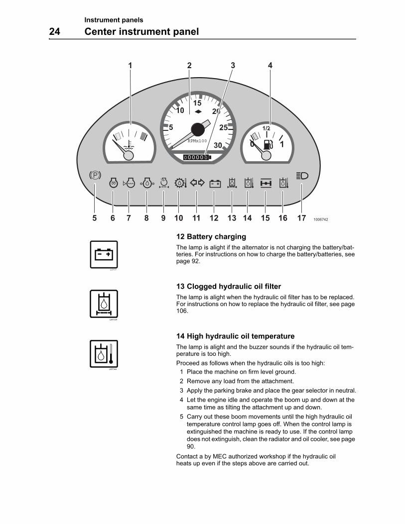
12 Battery charging
The lamp is alight if the alternator is not charging the battery/bat-teries. For instructions on how to charge the battery/batteries, see page 92.
13 Clogged hydraulic oil filter
The lamp is alight when the hydraulic oil filter has to be replaced. For instructions on how to replace the hydraulic oil filter, see page 106.
14 High hydraulic oil temperature
The lamp is alight and the buzzer sounds if the hydraulic oil tem-perature is too high.
Proceed as follows when the hydraulic oils is too high:
1 Place the machine on firm level ground.
2 Remove any load from the attachment.
3 Apply the parking brake and place the gear selector in neutral.
4 Let the engine idle and operate the boom up and down at the same time as tilting the attachment up and down.
5 Carry out these boom movements until the high hydraulic oil temperature control lamp goes off. When the control lamp is extinguished the machine is ready to use. If the control lamp does not extinguish, clean the radiator and oil cooler, see page 90.
Contact a by MEC authorized workshop if the hydraulic oil heats up even if the steps above are carried out.
km/h
000000
10
20
3040
60
50
0 0
RPMx100
1/2
0
2 3
6 875 9 10 11 12 13 14 15 16 17 1006742
41
L57177
L68733A
L68734A
Instrument panels
Center instrument panel 25
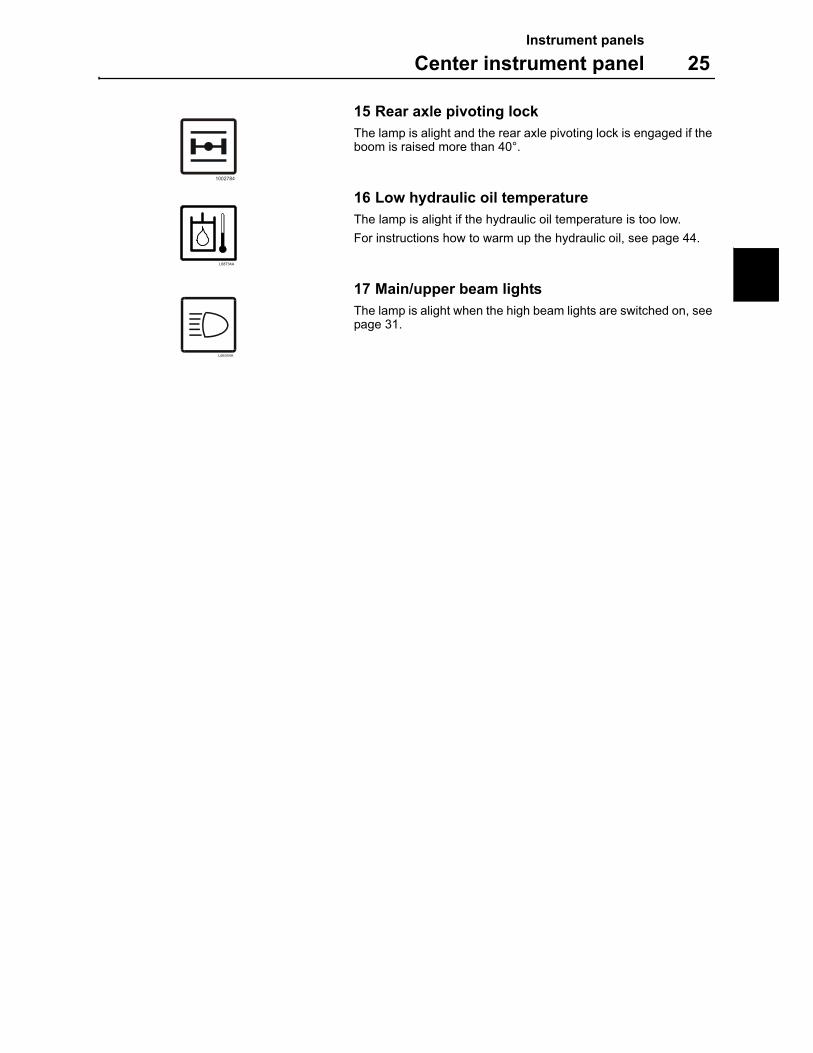
15 Rear axle pivoting lock
The lamp is alight and the rear axle pivoting lock is engaged if the boom is raised more than 40°.
16 Low hydraulic oil temperature
The lamp is alight if the hydraulic oil temperature is too low.
For instructions how to warm up the hydraulic oil, see page 44.
17 Main/upper beam lights
The lamp is alight when the high beam lights are switched on, see page 31.
1002784
L68734A
L66344A
Instrument panels
26 Right instrument panel
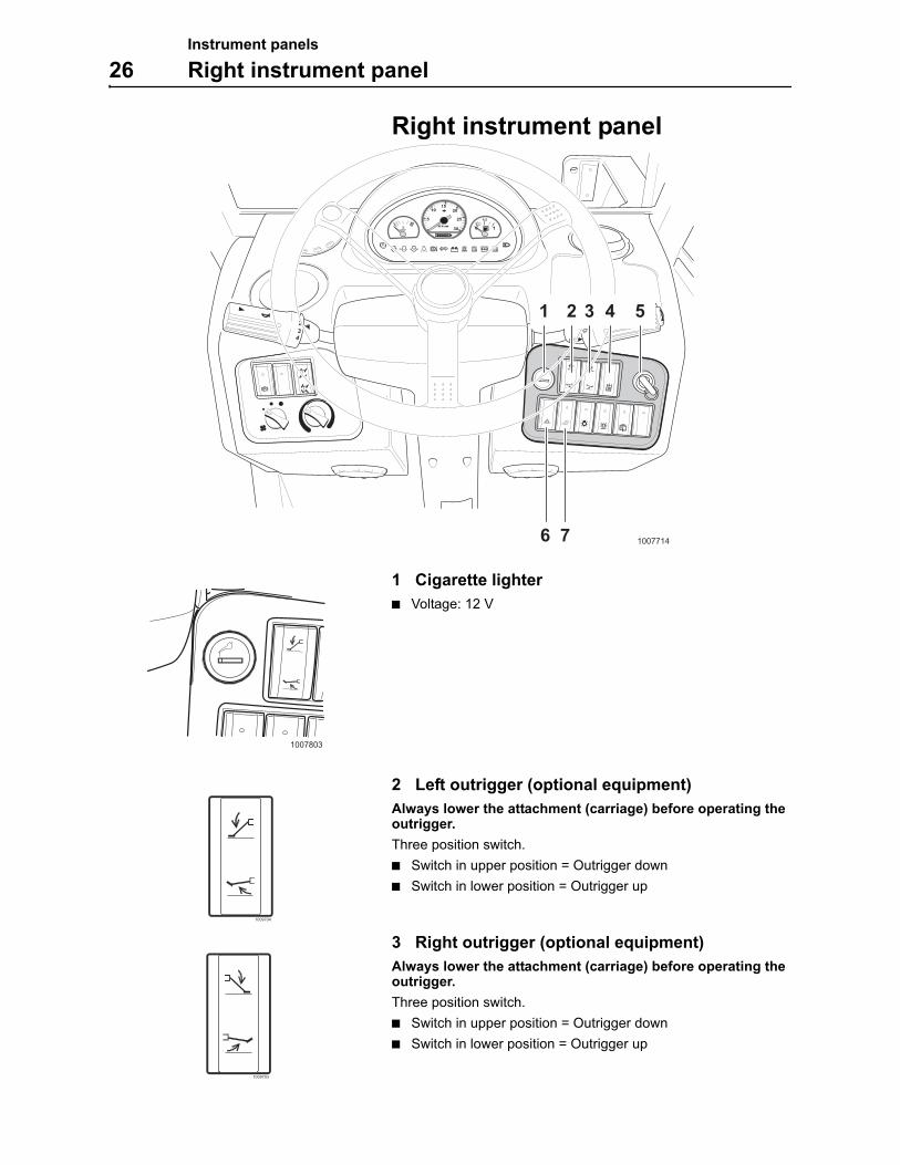
Right instrument panel
1 Cigarette lighter
Voltage: 12 V
2 Left outrigger (optional equipment)
Always lower the attachment (carriage) before operating the outrigger.
Three position switch.
Switch in upper position = Outrigger down
Switch in lower position = Outrigger up
3 Right outrigger (optional equipment)
Always lower the attachment (carriage) before operating the outrigger.
Three position switch.
Switch in upper position = Outrigger down
Switch in lower position = Outrigger up
1/2
0
023
4
1
10077146 7
1 2 3 4 5
1007803
1009704
1009703
Instrument panels
Right instrument panel 27
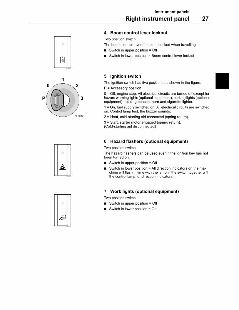
4 Boom control lever lockout
Two position switch.
The boom control lever should be locked when travelling.
Switch in upper position = Off
Switch in lower position = Boom control lever locked
5 Ignition switch
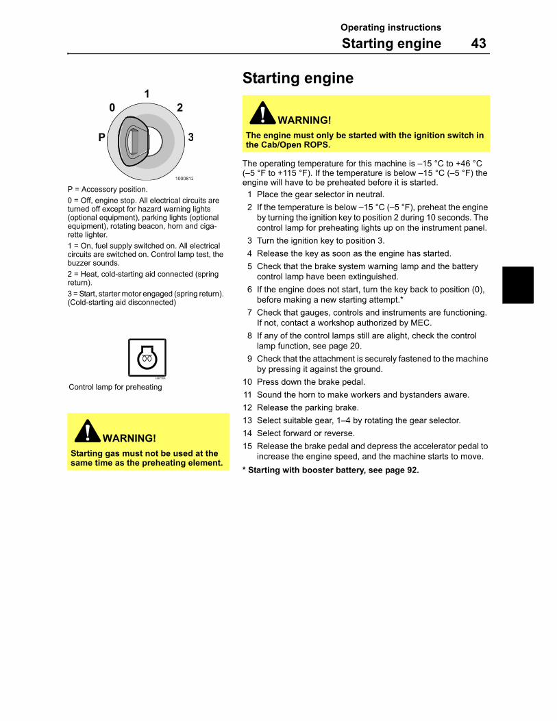
The ignition switch has five positions as shown in the figure.
P = Accessory position.
0 = Off, engine stop. All electrical circuits are turned off except for hazard warning lights (optional equipment), parking lights (optional equipment), rotating beacon, horn and cigarette lighter.
1 = On, fuel supply switched on. All electrical circuits are switched on. Control lamp test, the buzzer sounds.
2 = Heat, cold-starting aid connected (spring return).
3 = Start, starter motor engaged (spring return). (Cold-starting aid disconnected)
6 Hazard flashers (optional equipment)
Two position switch.
The hazard flashers can be used even if the ignition key has not been turned on.
Switch in upper position = Off
Switch in lower position = All direction indicators on the ma-chine will flash in time with the lamp in the switch together with the control lamp for direction indicators.
7 Work lights (optional equipment)
Two position switch.
Switch in upper position = Off
Switch in lower position = On
1007802
1000812
1
P 3
20
1000609
1000604
Instrument panels
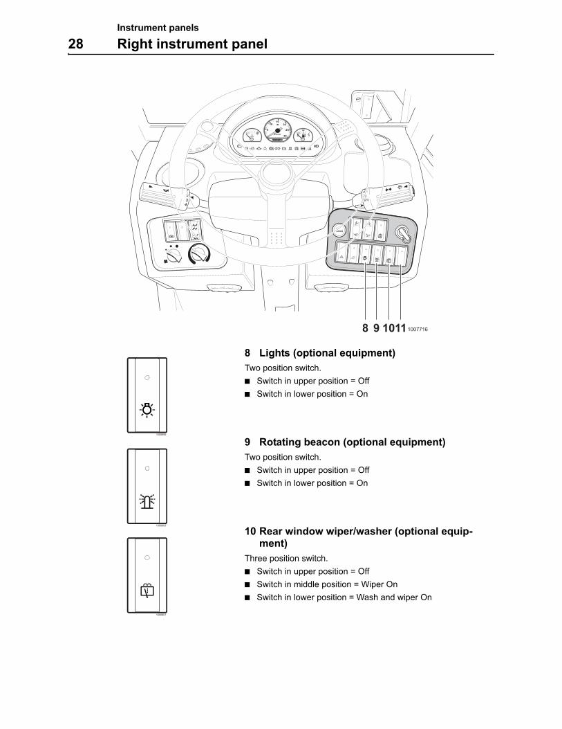
28 Right instrument panel
8 Lights (optional equipment)
Two position switch.
Switch in upper position = Off
Switch in lower position = On
9 Rotating beacon (optional equipment)
Two position switch.
Switch in upper position = Off
Switch in lower position = On
10 Rear window wiper/washer (optional equip-ment)
Three position switch.
Switch in upper position = Off
Switch in middle position = Wiper On
Switch in lower position = Wash and wiper On
1/2
0
023
4
1
10077168 9 1011
1000895
1000603
1000607
Other controls
Controls 29
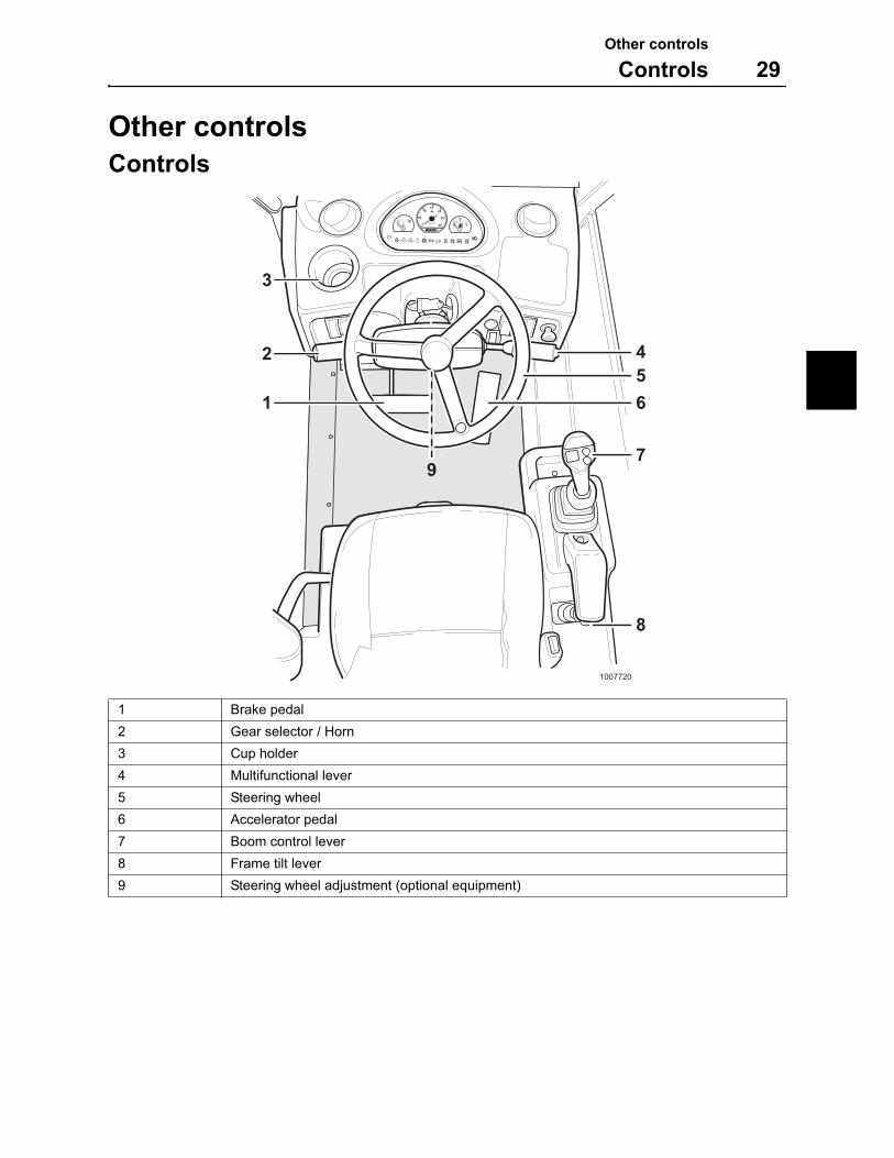
Other controls
Controls
1 Brake pedal
2 Gear selector / Horn
3 Cup holder
4 Multifunctional lever
5 Steering wheel
6 Accelerator pedal
7 Boom control lever
8 Frame tilt lever
9 Steering wheel adjustment (optional equipment)
1007720
2
1
3
456
7
8
9
km/h
000000
10
20
3040
60
50
0 0
RPMx100
1/2
0
Other controls
30 Controls
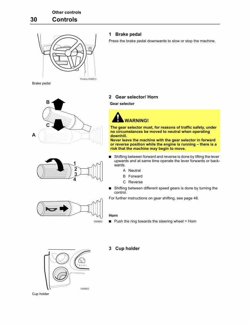
1 Brake pedal
Press the brake pedal downwards to slow or stop the machine.
2 Gear selector/ Horn
Gear selector
Shifting between forward and reverse is done by lifting the lever upwards and at same time operate the lever forwards or back-wards.
A Neutral
B Forward
C Reverse
Shifting between different speed gears is done by turning the control.
For further instructions on gear shifting, see page 48.
Horn
Push the ring towards the steering wheel = Horn
3 Cup holder
WARNING!
The gear selector must, for reasons of traffic safety, under no circumstances be moved to neutral when operating downhill.Never leave the machine with the gear selector in forward or reverse position while the engine is running – there is a risk that the machine may begin to move.
PicAdu1008812
Brake pedal
1009952
1234
B
A
C
1008802
Cup holder
Other controls
Controls 31
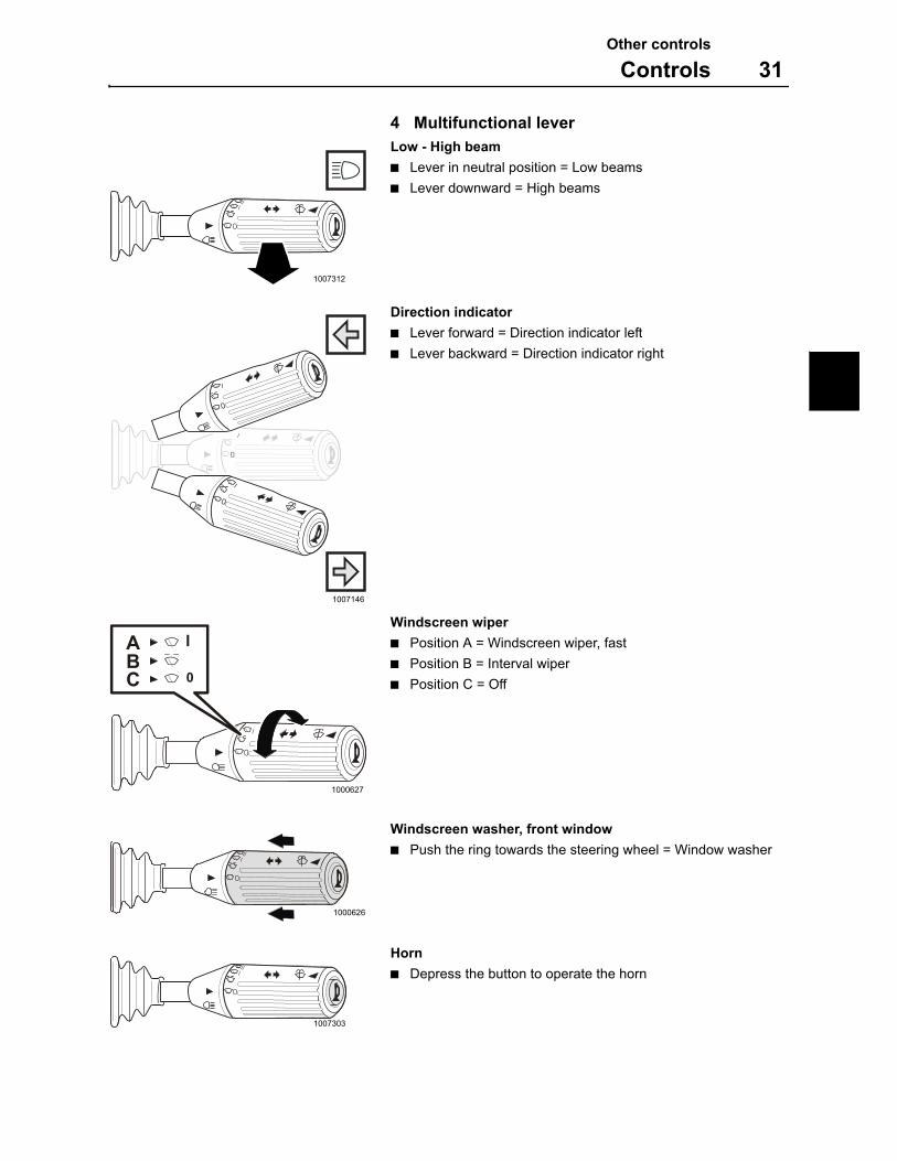
4 Multifunctional lever
Low - High beam
Lever in neutral position = Low beams
Lever downward = High beams
Direction indicator
Lever forward = Direction indicator left
Lever backward = Direction indicator right
Windscreen wiper
Position A = Windscreen wiper, fast
Position B = Interval wiper
Position C = Off
Windscreen washer, front window
Push the ring towards the steering wheel = Window washer
Horn
Depress the button to operate the horn
1007312
0
III
1007146
0
I
0
I
0
I
1000627
0
I
0CBA I
1000626
0
III
1000626
0
III
1007303
0
III
Other controls
32 Controls
5 Steering wheel
The machine is equipped with three steering modes, two-wheel steer, four-wheel steer and crab steer.
For information how to steer the machine, see page 45.
6 Accelerator pedal
Press the pedal downwards to increase the engine speed. When the pedal is released the engine speed will decrease.
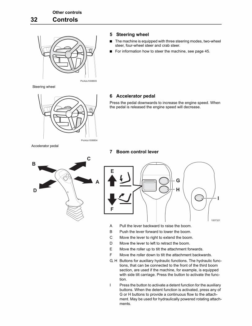
7 Boom control lever
A Pull the lever backward to raise the boom.
B Push the lever forward to lower the boom.
C Move the lever to right to extend the boom.
D Move the lever to left to retract the boom.
E Move the roller up to tilt the attachment forwards.
F Move the roller down to tilt the attachment backwards.
G, H Buttons for auxiliary hydraulic functions. The hydraulic func-tions, that can be connected to the front of the third boom section, are used if the machine, for example, is equipped with side tilt carriage. Press the button to activate the func-tion.
I Press the button to activate a detent function for the auxiliary buttons. When the detent function is activated, press any of G or H buttons to provide a continuous flow to the attach-ment. May be used for hydraulically powered rotating attach-ments.
PicAdu1008805
Steering wheel
PicAdu1008804
Accelerator pedal
H
G
I
1007321
BC
DA
E
F
Other controls
Controls 33
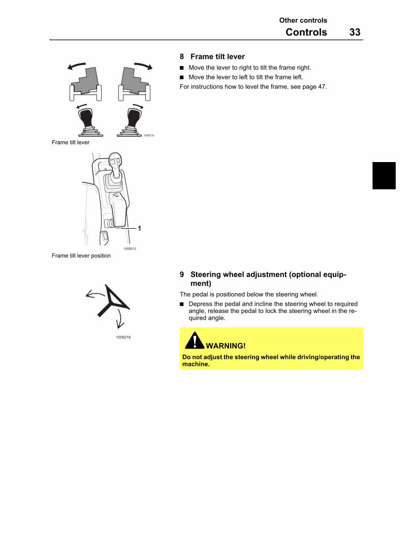
8 Frame tilt lever
Move the lever to right to tilt the frame right.
Move the lever to left to tilt the frame left.
For instructions how to level the frame, see page 47.
9 Steering wheel adjustment (optional equip-ment)
The pedal is positioned below the steering wheel.
Depress the pedal and incline the steering wheel to required angle, release the pedal to lock the steering wheel in the re-quired angle.
WARNING!
Do not adjust the steering wheel while driving/operating the machine.
1009731
Frame tilt lever
1008512
1
Frame tilt lever position
1009216
Other controls
34 Operator comfort
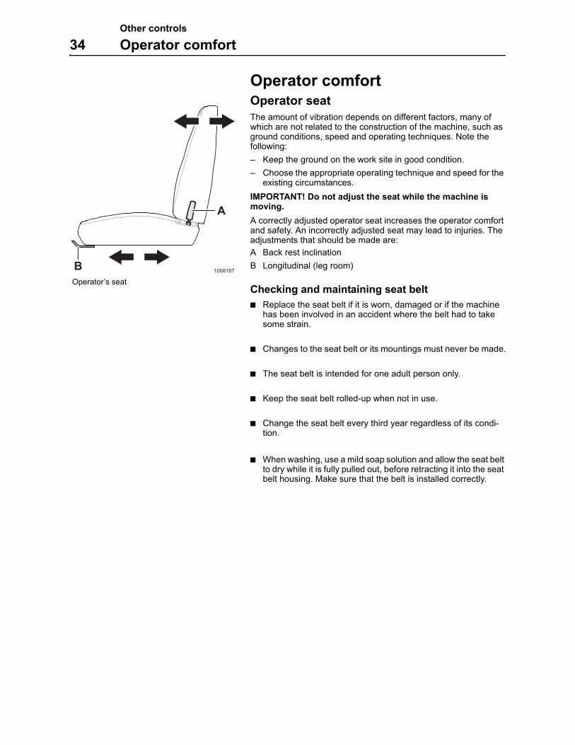
Operator comfortOperator seat
The amount of vibration depends on different factors, many of which are not related to the construction of the machine, such as ground conditions, speed and operating techniques. Note the following:
– Keep the ground on the work site in good condition.
– Choose the appropriate operating technique and speed for the existing circumstances.
IMPORTANT! Do not adjust the seat while the machine is moving.
A correctly adjusted operator seat increases the operator comfort and safety. An incorrectly adjusted seat may lead to injuries. The adjustments that should be made are:
A Back rest inclination
B Longitudinal (leg room)
Checking and maintaining seat belt
Replace the seat belt if it is worn, damaged or if the machine has been involved in an accident where the belt had to take some strain.
Changes to the seat belt or its mountings must never be made.
The seat belt is intended for one adult person only.
Keep the seat belt rolled-up when not in use.
Change the seat belt every third year regardless of its condi-tion.
When washing, use a mild soap solution and allow the seat belt to dry while it is fully pulled out, before retracting it into the seat belt housing. Make sure that the belt is installed correctly.
A
B1008187
Operator’s seat
Operating instructions
35
Operating instructionsThis chapter contains rules which must be followed to make work-ing with the machine safe. However, these rules do not relieve the operator from following laws or other national regulations for traffic safety, industrial safety and labour welfare.
To avoid the risk of accidents, alertness, judgement and respect for applicable safety regulations is a condition.
Running-in
During the first 50 hours, the machine should be operated with a certain amount of care. During the running-in period it is important to check oil and fluid levels often.
Wheel bolts are to be check-tightened after the first eight hours of operation, see page 103.
Operating instructions
36 Safety rules when operating
Safety rules when operatingOperator duties
Read and understand the Operator's Manual.
The machine operator must operate the machine in such a way that the risk of accidents is minimized for both operator, other road users and persons present at the work site.
Never allow an untrained or unqualified person to operate the machine.All operators must be trained according to OSHA regulation 1910.178.
OSHA regulations 1910.178 and 1926.602, and ANSI StandardASME B56.6-2002 must be read and understood.
Read and understand the EMI Safety Manual for rough terrain forklifts.
The machine operator must be thoroughly familiar with how to operate and maintain the machine and should undergo required training on the machine.
The machine operator must follow the rules and recommenda-tions given in the Operator's Manual, but also pay attention to any statutory and national regulations or specific requirements or risks that apply at the work site.
The machine operator must be thoroughly rested and must never operate the machine under the influence of alcohol, medicine or other drugs.
The machine operator is responsible for the load of the ma-chine both when travelling on public roads as well as when working on site.
– There must be no risk of the load falling off while operating.
– Refuse to take a load which is an obvious safety risk.
– Respect the stated maximum load for the machine. Pay atten-tion to the effect of different distances to the center of gravity and the influence of different attachments.
The machine operator must be in charge of the working area of the machine.
– Prevent persons from walking or standing under raised boom, unless the boom have been made safe or supported.
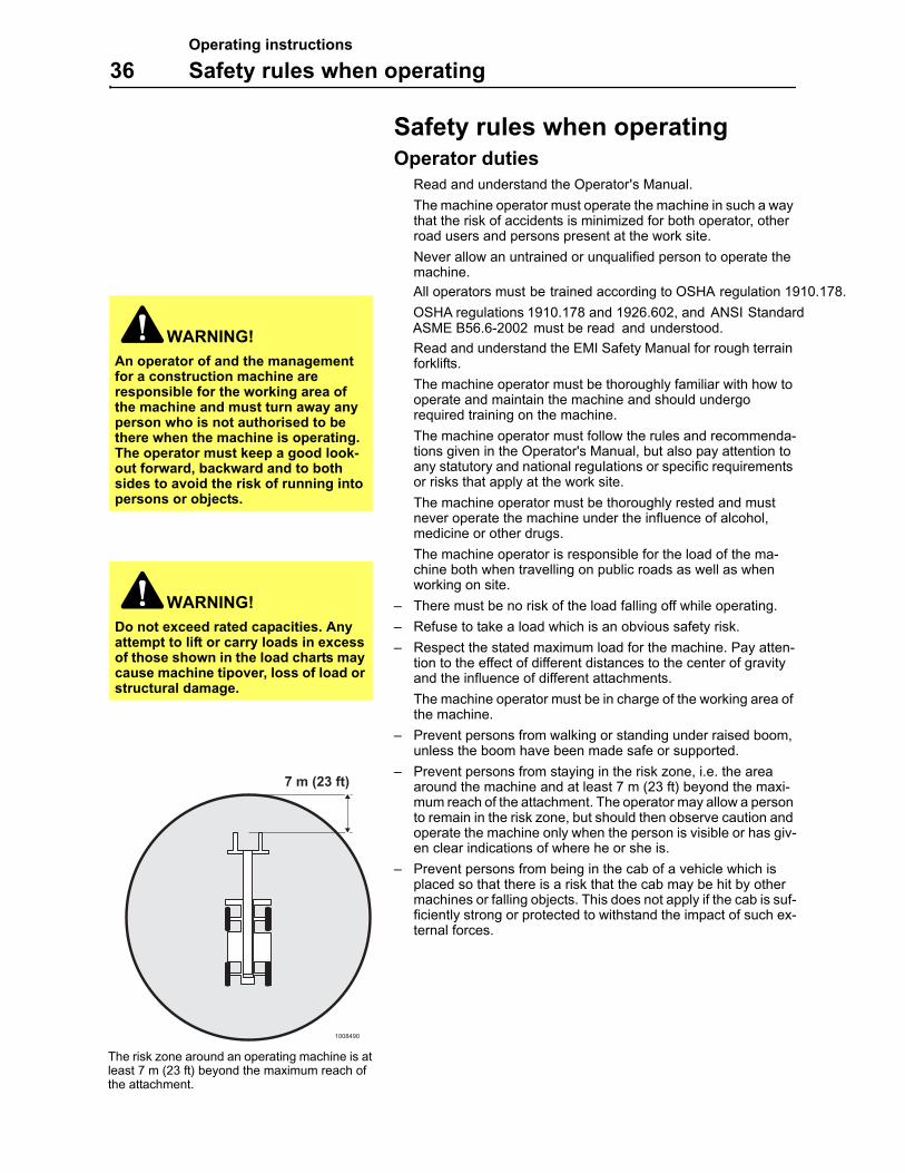
– Prevent persons from staying in the risk zone, i.e. the area around the machine and at least 7 m (23 ft) beyond the maxi-mum reach of the attachment. The operator may allow a person to remain in the risk zone, but should then observe caution and operate the machine only when the person is visible or has giv-en clear indications of where he or she is.
– Prevent persons from being in the cab of a vehicle which is placed so that there is a risk that the cab may be hit by other machines or falling objects. This does not apply if the cab is suf-ficiently strong or protected to withstand the impact of such ex-ternal forces.
WARNING!
An operator of and the management for a construction machine are responsible for the working area of the machine and must turn away any person who is not authorised to be there when the machine is operating. The operator must keep a good look-out forward, backward and to both sides to avoid the risk of running into persons or objects.
WARNING!Do not exceed rated capacities. Any attempt to lift or carry loads in excess of those shown in the load charts may cause machine tipover, loss of load or structural damage.
1008490
7 m (23 ft)
The risk zone around an operating machine is at least 7 m (23 ft) beyond the maximum reach of the attachment.
Operating instructions
Safety rules when operating 37
AccidentsAccidents and incidents should be reported to the site manage-ment immediately.
If possible leave the machine in position.
Only take necessary action so as to reduce the effect of dam-age, especially personal injuries. Avoid action which may make an investigation more difficult.
Wait for further instructions from the site management.
Machine operator safetyThe machine must be operational, i.e. faults which can cause accidents must be rectified.
Suitable clothing for safe handling should be worn.
Always sit in the operator seat when starting the engine/ma-chine.
Keep your hands and feet away from areas where there is a risk of crushing, e.g. covers, doors and windows.
Always use the lap type seat belt.
Use steps and handholds when entering or leaving the ma-chine. Use the three-point grip, i.e. two hands and one foot or two feet and one hand. Always face the machine – do not jump!
The door should be closed.
Check that any attachment is properly attached and locked.
The vibrations (shaking) which arises when operating may be harmful to the operator. Reduce this by:
– adjusting the seat and tightening the seat belt.
– picking the smoothest operating surface for the machine (leveling the surface when necessary).
– adapting the speed.
The cab is for the protection of the machine operator and it meets the requirements for Roll Over Protective Structures ac-cording to the testing standard "ROPS". Therefore, hold firmly onto the steering wheel if the machine should roll over – do not jump!
The cab is also designed to meet the requirements for falling objects, the weight of which agrees with testing methods ac-cording to "FOPS".
Keep hands and feet inside the operator's designated area or compartment. Do not put any part of the body outside of the Cab/Open ROPS of the machine.
Only step or stand on surfaces which are provided with anti-slip protection.
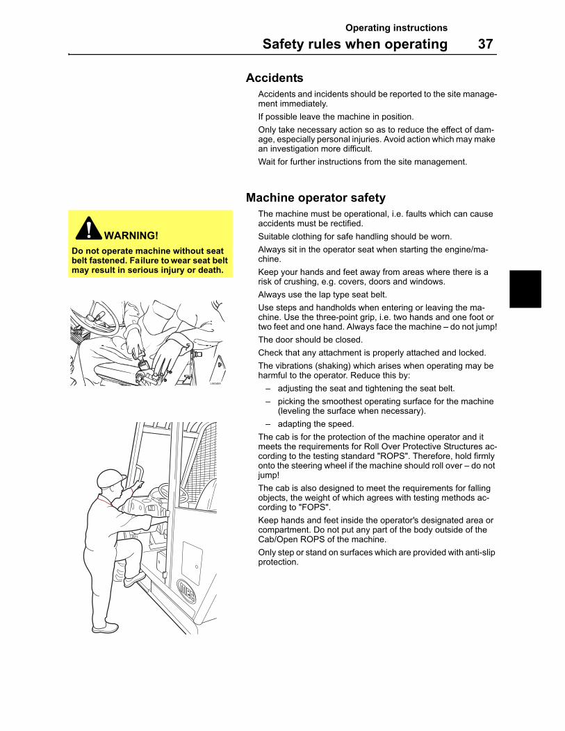
WARNING!
Do not operate machine without seat belt fastened. Failure to wear seat belt may result in serious injury or death.
Operating instructions
38 Safety rules when operating
Working within dangerous areas
Working within areas where there are pipes, power lines or cables
It is the duty of the employer to know and mark the position of pipes for gas, water, sewage or power lines or cables on the work site and to inform the operator about these. Failure to do so may have legal consequences. When required, local author-ities and/or communication and power companies should be contacted regarding maps, drawings and advice.
Cables and power lines must be protected against damage in a suitable way. Electric cables should, if possible, have the power turned off.
Information about where the gas and water can be turned off should be made available, so that these supplies can be quickly turned off, if they are ruptured.
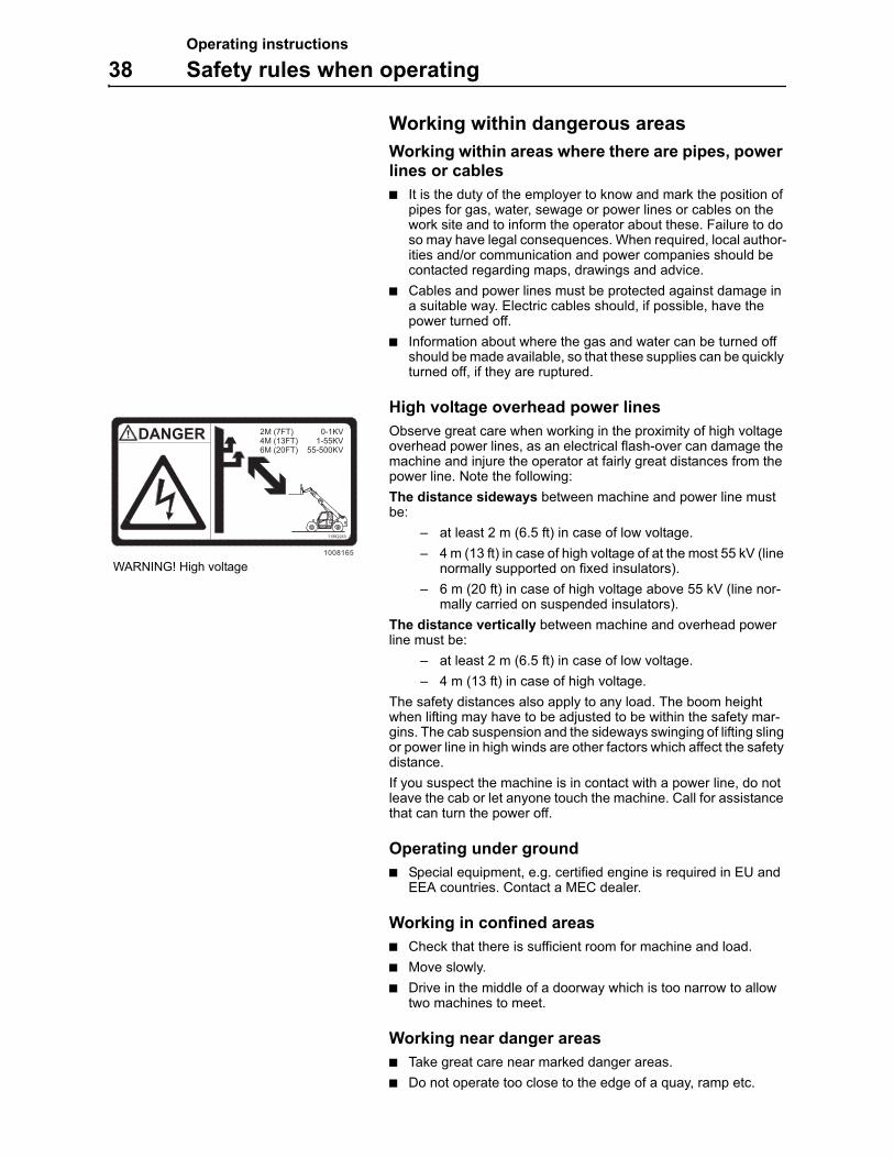
High voltage overhead power lines
Observe great care when working in the proximity of high voltage overhead power lines, as an electrical flash-over can damage the machine and injure the operator at fairly great distances from the power line. Note the following:
The distance sideways between machine and power line must be:
– at least 2 m (6.5 ft) in case of low voltage.
– 4 m (13 ft) in case of high voltage of at the most 55 kV (line normally supported on fixed insulators).
– 6 m (20 ft) in case of high voltage above 55 kV (line nor-mally carried on suspended insulators).
The distance vertically between machine and overhead power line must be:
– at least 2 m (6.5 ft) in case of low voltage.
– 4 m (13 ft) in case of high voltage.
The safety distances also apply to any load. The boom height when lifting may have to be adjusted to be within the safety mar-gins. The cab suspension and the sideways swinging of lifting sling or power line in high winds are other factors which affect the safety distance.
If you suspect the machine is in contact with a power line, do not leave the cab or let anyone touch the machine. Call for assistance that can turn the power off.
Operating under ground
Special equipment, e.g. certified engine is required in EU and EEA countries. Contact a MEC dealer.
Working in confined areas
Check that there is sufficient room for machine and load.
Move slowly.
Drive in the middle of a doorway which is too narrow to allow two machines to meet.
Working near danger areas
Take great care near marked danger areas.
Do not operate too close to the edge of a quay, ramp etc.
2M (7FT) 0-1KV4M (13FT) 1-55KV6M (20FT) 55-500KV
11862243
1008165
DANGER
WARNING! High voltage
Operating instructions
Safety rules when operating 39
Travelling and operating (working) on public roads
A machine operator is considered to be a road-user and therefore required to know and follow applicable traffic regulations.
It is important to bear in mind that the machine, in comparison with the rest of the traffic, is a slow moving and wide machine, which may cause obstruction. Bear this in mind and pay attention to the traffic behind you. Facilitate overtaking.
The use of a SMV-plate (Slow Moving Vehicle plate) is recom-mended. It should be positioned on the machine where it is easily visible, not inside the rear window or any other window. It should be positioned at a height of 0.6–1.8 m (2–6 ft) above the ground, measured from the lower edge of the plate. Pay attention to nation-al traffic regulations.
The boom must be in travelling position while driving on public roads.
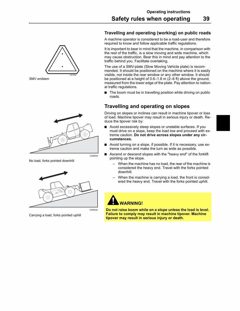
Travelling and operating on slopes
Driving on slopes or inclines can result in machine tipover or loss of load. Machine tipover may result in serious injury or death. Re-duce the tipover risk by:
Avoid excessively steep slopes or unstable surfaces. If you must drive on a slope, keep the load low and proceed with ex-treme caution. Do not drive across slopes under any cir-cumstances.
Avoid turning on a slope, if possible. If it is necessary, use ex-treme caution and make the turn as wide as possible.
Ascend or descend slopes with the "heavy end" of the forklift pointing up the slope.
– When the machine has no load, the rear of the machine is considered the heavy end. Travel with the forks pointed downhill.
– When the machine is carrying a load, the front is consid-ered the heavy end. Travel with the forks pointed uphill.
WARNING!
Do not raise boom while on a slope unless the load is level. Failure to comply may result in machine tipover. Machine tipover may result in serious injury or death.
L66358A
SMV emblem
1008656
Carrying a load, forks pointed uphill
1008655
No load, forks pointed downhill
Operating instructions
40 Center of gravity
Center of gravity
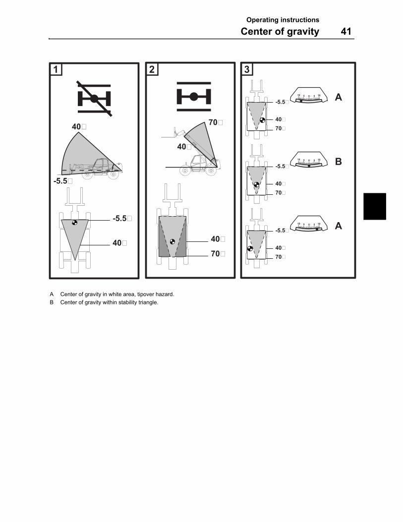
1 Boom angle below 40 degrees
The rear axle pivoting lock is disengaged when the boom is be-low 40°. The machine is now easy to manouver while transport-ing loads and driving the machine on the work site or on the road.
Even if the rear axle pivoting lock is disengaged under 40°, it is not allowed to transport the load with the boom raised. The boom must always be lowered when transporting a load or driv-ing the machine.
Remember that a small pot hole on the work site or even a sink-ing wheel can make the load unstable, this may lead to ma-chine tipover or falling object hazard.
2 Boom angle between 40 and 70 degrees
When the boom is raised more than 40 degrees, the pivoting axle lock will be engaged. This means that the stability of the machine is increased during operation. Note that the axle piv-oting lock helps the center of gravity to stay within the stability triangle. Operating with loads over 40° does not mean that tipover hazard is excluded.
Remember that a small pot hole on the work site or even a sink-ing wheel can make the load unstable, this may lead to ma-chine tipover or falling object hazard.
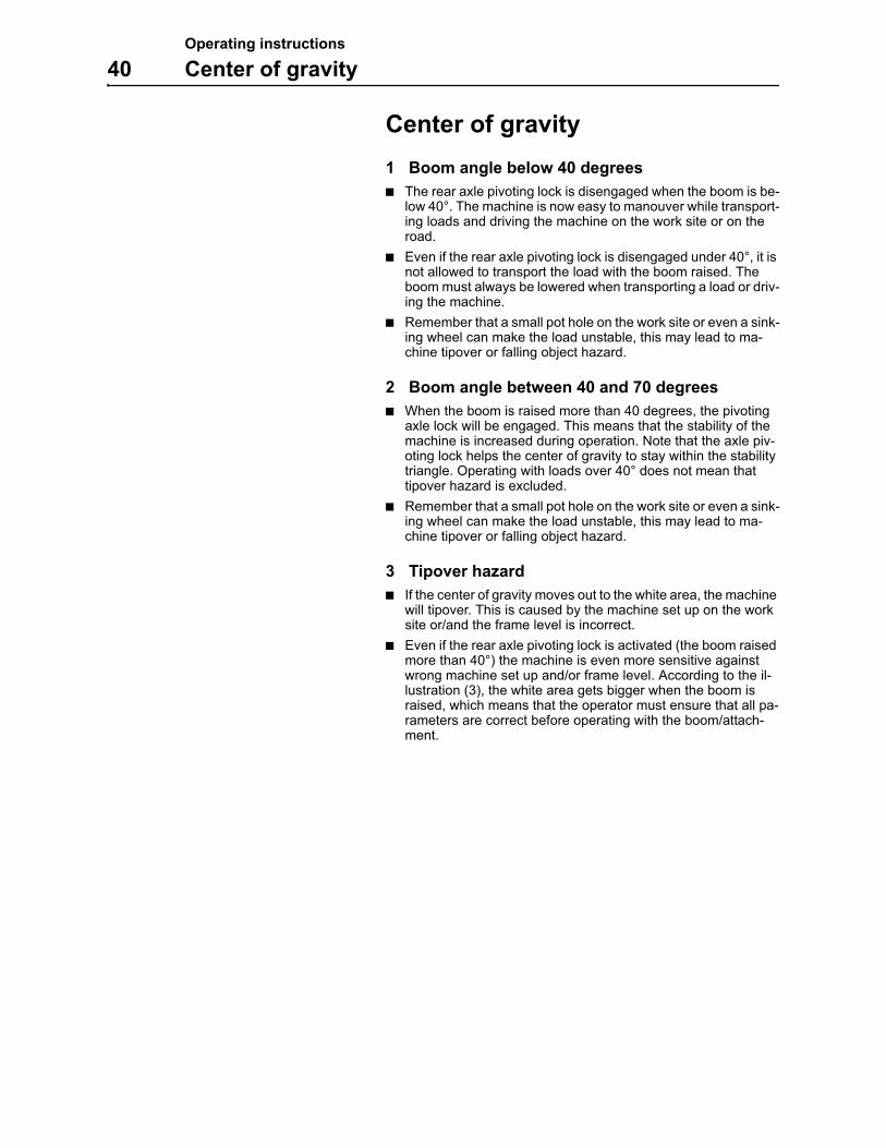
3 Tipover hazard
If the center of gravity moves out to the white area, the machine will tipover. This is caused by the machine set up on the work site or/and the frame level is incorrect.
Even if the rear axle pivoting lock is activated (the boom raised more than 40°) the machine is even more sensitive against wrong machine set up and/or frame level. According to the il-lustration (3), the white area gets bigger when the boom is raised, which means that the operator must ensure that all pa-rameters are correct before operating with the boom/attach-ment.
Operating instructions
Center of gravity 41
40�
70�
40�
70�
40�
-5.5�
70�40�
-5.5�
-5.5�
40�
1 2 3
10 5 0� 5 10
40�
-5.5�
70�
10 5 0� 5 10
40�
-5.5�
70�
10 5 0� 5 10
A
B
A
A Center of gravity in white area, tipover hazard.
B Center of gravity within stability triangle.
Operating instructions
42 Measures before operating
Measures before operating1 Carry out daily service, see page 109.
2 Ensure good visibility.
3 Clean headlights, safety decals, handholds and footsteps.
4 Check for damage to the tires and check the tire pressure, see page 103.
5 Check that the battery disconnect switch is turned on, see page 91.
6 Check that the wheels are not blocked.
7 Check that the engine hood, fuel cover and tool box is closed.
8 Check for loose, damaged or missing parts.
9 Enter the Cab/Open ROPS by using the three-point grip.
10 Fasten the seat belt.
11 Turn the gear selector into neutral.
12 Make workers and bystanders aware.
13 Start the engine.
Additional measures in cold weather
Make sure that the freezing point of the coolant corresponds to the weather conditions, see page 88.
Use the recommended lubricating oil for winter use, see page 117.
After operating
Fill the fuel tank, as this will counteract the formation of conden-sation water.
IMPORTANT! If the fuel tank has been run dry or if air for any reason has entered the fuel system, this must be bled before the engine can be started, see page 84.
WARNING!
The machine must operate on ground that can manage to carry the machine weight. The condition of the ground should be checked before the machine is used.
Operating instructions
Starting engine 43
Starting engine
The operating temperature for this machine is –15 °C to +46 °C (–5 °F to +115 °F). If the temperature is below –15 °C (–5 °F) the engine will have to be preheated before it is started.
1 Place the gear selector in neutral.
2 If the temperature is below –15 °C (–5 °F), preheat the engine by turning the ignition key to position 2 during 10 seconds. The control lamp for preheating lights up on the instrument panel.
3 Turn the ignition key to position 3.
4 Release the key as soon as the engine has started.
5 Check that the brake system warning lamp and the battery control lamp have been extinguished.
6 If the engine does not start, turn the key back to position (0), before making a new starting attempt.*
7 Check that gauges, controls and instruments are functioning. If not, contact a workshop authorized by MEC.
8 If any of the control lamps still are alight, check the control lamp function, see page 20.
9 Check that the attachment is securely fastened to the machine by pressing it against the ground.
10 Press down the brake pedal.
11 Sound the horn to make workers and bystanders aware.
12 Release the parking brake.
13 Select suitable gear, 1–4 by rotating the gear selector.
14 Select forward or reverse.
15 Release the brake pedal and depress the accelerator pedal to increase the engine speed, and the machine starts to move.
* Starting with booster battery, see page 92.
WARNING!
The engine must only be started with the ignition switch in the Cab/Open ROPS.
WARNING!
Starting gas must not be used at the same time as the preheating element.
1000812
1
P 3
20
P = Accessory position.
0 = Off, engine stop. All electrical circuits are turned off except for hazard warning lights (optional equipment), parking lights (optional equipment), rotating beacon, horn and ciga-rette lighter.
1 = On, fuel supply switched on. All electrical circuits are switched on. Control lamp test, the buzzer sounds.
2 = Heat, cold-starting aid connected (spring return).
3 = Start, starter motor engaged (spring return). (Cold-starting aid disconnected)
L68730A
Control lamp for preheating
Operating instructions
44 Starting engine
Hydraulic system, warming up
When the oil is cold, it is viscous. For this reason some machine functions will be slower than when the oil is hot. Therefore it is im-portant that the oil in the hydraulic system is properly warmed up before operating the machine.
To race the engine immediately after it has been started may also endanger the lubrication and cooling of the turbocharger with great risk of bearing seizure as a consequence.
Moving the machine a short distance (for example when loading onto or off a trailer) can be done without a complete warm up. These operations must be executed with great care. In such situ-ations, the engine speed must not exceed 1200 rpm.
1 Apply the parking brake.
2 Start the engine and let it idle for five minutes.
3 Lower the stabilizers and the loader boom to the ground.
4 Increase the engine speed to 1000 rpm.
5 Raise and lower the boom with full lever travel.
6 Tilt the attachment up and down with full lever travel.
7 Extend and retract the boom half way out while the boom is lowered.
8 Then make a series of boom and transport movements to dis-tribute the heated hydraulic oil to the hydraulic cylinders and the pump.
9 Continue making these movements until the hydraulic system has warmed up.
10 Release the parking brake and drive the machine forwards and backwards on level ground. This is to ensure that the axles have proper lubrication.
It is forbidden to force the oil warming up process. Forced warm up can damage the machine.
Operating instructions
Steering 45
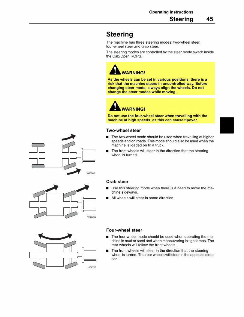
SteeringThe machine has three steering modes: two-wheel steer, four-wheel steer and crab steer.
The steering modes are controlled by the steer mode switch inside the Cab/Open ROPS.
Two-wheel steer
The two-wheel mode should be used when travelling at higher speeds and on roads. This mode should also be used when the machine is loaded on to a truck.
The front wheels will steer in the direction that the steering wheel is turned.
Crab steer
Use this steering mode when there is a need to move the ma-chine sideways.
All wheels will steer in same direction.
Four-wheel steer
The four-wheel mode should be used when operating the ma-chine in mud or sand and when maneuvering in tight areas. The rear wheels will follow the front wheels.
The front wheels will steer in the direction that the steering wheel is turned. The rear wheels will steer in the opposite direc-tion.
WARNING!
As the wheels can be set in various positions, there is a risk that the machine steers in uncontrolled way. Before changing steer mode, always align the wheels. Do not change the steer modes while moving.
WARNING!
Do not use the four-wheel steer when travelling with the machine at high speeds, as this can cause tipover.
1006766
1006765
1006763
Operating instructions
46 Steering
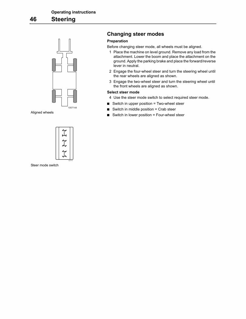
Changing steer modes
Preparation
Before changing steer mode, all wheels must be aligned.
1 Place the machine on level ground. Remove any load from the attachment. Lower the boom and place the attachment on the ground. Apply the parking brake and place the forward/reverse lever in neutral.
2 Engage the four-wheel steer and turn the steering wheel until the rear wheels are aligned as shown.
3 Engage the two-wheel steer and turn the steering wheel until the front wheels are aligned as shown.
Select steer mode
4 Use the steer mode switch to select required steer mode.
Switch in upper position = Two-wheel steer
Switch in middle position = Crab steer
Switch in lower position = Four-wheel steer
1007144
Aligned wheels
1007770
Steer mode switch
Operating instructions
Leveling the machine frame 47
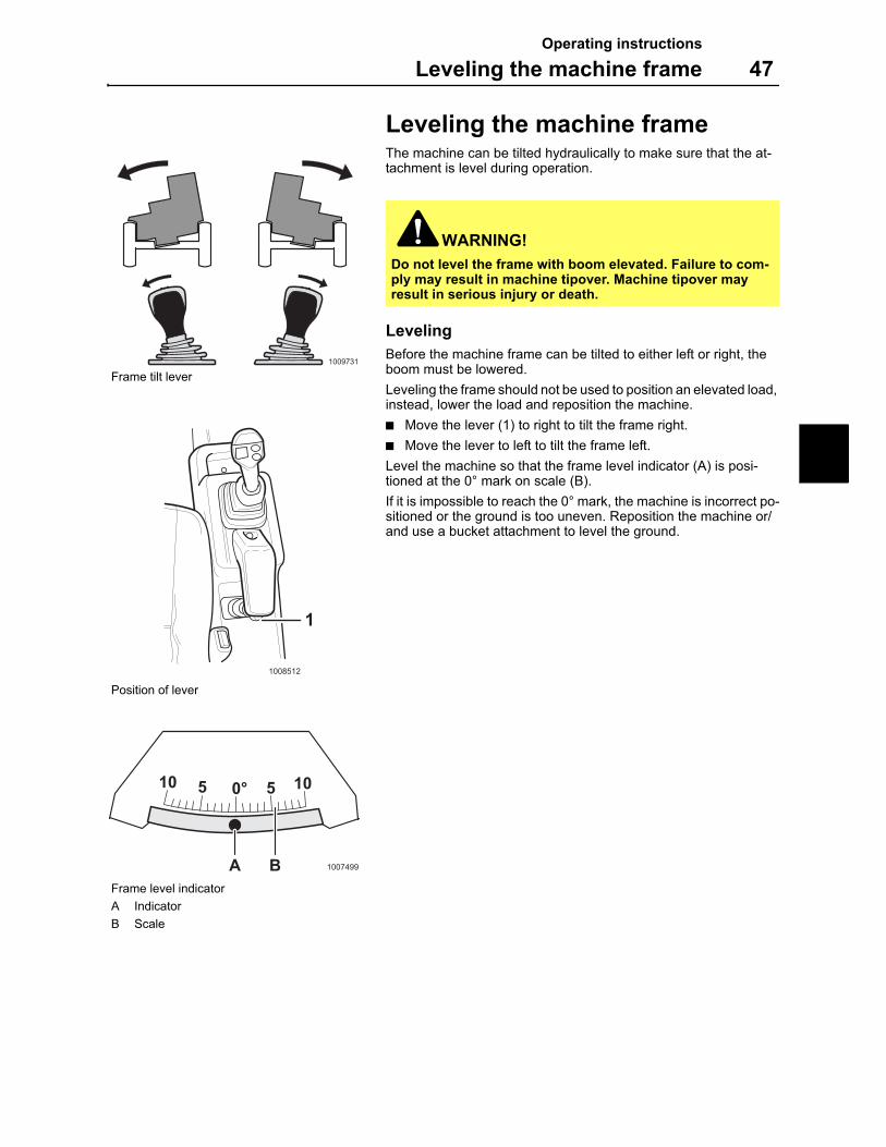
Leveling the machine frameThe machine can be tilted hydraulically to make sure that the at-tachment is level during operation.
Leveling
Before the machine frame can be tilted to either left or right, the boom must be lowered.
Leveling the frame should not be used to position an elevated load, instead, lower the load and reposition the machine.
Move the lever (1) to right to tilt the frame right.
Move the lever to left to tilt the frame left.
Level the machine so that the frame level indicator (A) is posi-tioned at the 0° mark on scale (B).
If it is impossible to reach the 0° mark, the machine is incorrect po-sitioned or the ground is too uneven. Reposition the machine or/and use a bucket attachment to level the ground.
WARNING!
Do not level the frame with boom elevated. Failure to com-ply may result in machine tipover. Machine tipover may result in serious injury or death.
1009731
Frame tilt lever
1008512
1
Position of lever
10 5 0° 5 10
A B 1007499
Frame level indicator
A Indicator
B Scale
Operating instructions
48 Gear shifting
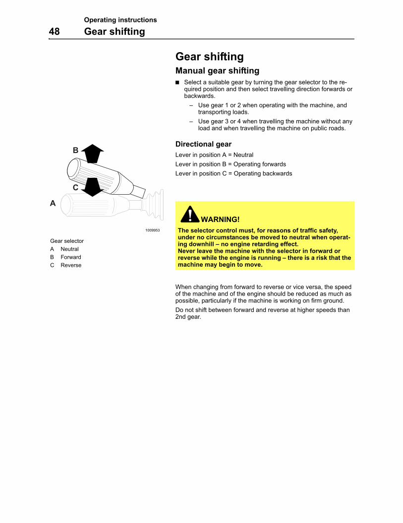
Gear shiftingManual gear shifting
Select a suitable gear by turning the gear selector to the re-quired position and then select travelling direction forwards or backwards.
– Use gear 1 or 2 when operating with the machine, and transporting loads.
– Use gear 3 or 4 when travelling the machine without any load and when travelling the machine on public roads.
Directional gear
Lever in position A = Neutral
Lever in position B = Operating forwards
Lever in position C = Operating backwards
When changing from forward to reverse or vice versa, the speed of the machine and of the engine should be reduced as much as possible, particularly if the machine is working on firm ground.
Do not shift between forward and reverse at higher speeds than 2nd gear.
WARNING!
The selector control must, for reasons of traffic safety, under no circumstances be moved to neutral when operat-ing downhill – no engine retarding effect.Never leave the machine with the selector in forward or reverse while the engine is running – there is a risk that the machine may begin to move.
1009953
B
A
C
Gear selector
A Neutral
B Forward
C Reverse
Operating instructions
Braking 49
BrakingBrake smoothly! This is particularly important when operating with a load and on slippery ground.
IMPORTANT! Do not apply the parking brake while driving the machine. The parking brake should only be used when the machine has been stopped or as a machine emergency brake.
Brake test
Carry out the brake tests as required. Always use the seat belt when using the machine.
Conditions
Acceptable values can only be obtained if the test is carried out on dry asphalt, dry concrete or other similar surfaces.
Make sure that the working area around the machine is clear of persons.
The machine must not be loaded.
Service brake, static checking
1 Stop the machine.
2 Depress the service brake pedal fully.
3 Release the parking brake.
4 Select second gear and put the forward/reverse lever into for-ward gear.
5 Depress the accelerator pedal fully.
6 The machine should stand still.
7 If the machine moves, contact a by MEC authorized work-shop.
Service brake, dynamic checking
1 Run the machine to maximum speed in second gear on dry as-phalt ground.
2 Depress the service brake pedal to fully.
3 Measure the brake distance.
The braking distance should not exceed 1 m (3.28 ft). If the maxi-mum braking distance is exceeded, contact a by MEC author-ized workshop.
Parking brake, checking
The parking brake should always be capable of holding the ma-chine stationary on 15 % dry swept-concrete grade under all con-ditions of loading in both forward and reverse directions. If there is any suspicion that the parking brake does not have the intended function, it should be checked by a MEC authorized workshop.
WARNING!
Brake test and checking the parking brake should only be done within an area where it cannot cause accidents.
Operating instructions
50 Stopping the machine
Stopping the machineThe machine is stopped in the following way:
1 Reduce the engine speed.
2 Apply the brake and when the machine is stationary move the gear selector to neutral.
3 Lower the attachments to the ground.
4 Apply the parking brake, see page 18. The parking brake will automatically be applied when turning the ignition key to off po-sition.
Stopping the engine
1 Let the engine idle a couple of minutes before turning it off in order to safeguard the lubrication and cooling of the turbo-charger.
2 Turn the ignition key to 0, so that the control lamps go out and the engine stops.
Do not leave the machine with the engine running.
WARNING!
When you are entering or leaving the machine, always face the machine and use the steps or hand holds to avoid slip-ping. Always use the "three-point" grip, i.e. both hands and one foot or both feet and one hand, when entering or leav-ing – Do not jump!
Operating instructions
Parking 51
Parking1 Place the machine on level ground, if possible. Otherwise,
block the wheels so that the machine cannot start moving. Lower the attachment against the ground.
2 Apply the parking brake. Check that the control lamp is alight. The parking brake will be applied automatically when the en-gine is turned off.
3 Check that all switches and controls are in the "off" position or in neutral.
4 Remove the ignition key.
5 If the machine is to be left unattended for some time, turn off the current supply with the battery disconnect switch, see page 91.
6 Lock all covers, fuel cap, windows and the doors.
Long-term parking and storage
1 Carry out the measures as described above.
2 Place the machine in service position 1, see page 70.
3 Wash the machine and touch up the paint finish to avoid rusting.
4 Treat exposed parts with anti-rust agent, lubricate the machine thoroughly and apply grease to unpainted surfaces.
5 Check the tire pressure, see page 130.
6 Fill the fuel tank and the hydraulic oil tank to the max. marks to minimize condensation water in the tanks.
7 Cover the exhaust pipe (not with plastic) if parking outdoors and close the engine hood.
8 Remove the battery if the machine is stored for more than three months. When the battery is removed, connect it to a battery charger for maintenance charging.
IMPORTANT! If the machine is stored for long periods or dis-abled, block the wheels.
After long-term parking/storage
Check all oil and fluid levels.
Check the condition of the fan belt.
Check the tire pressure.
Check the air cleaner.
Check the battery/batteries.
Check for possible leakage.
Remove the cover from the exhaust pipe.
Remove all anti-rust agents and other corrosion protection.
Test-run the machine until the engine, hydraulic system and other components have reached normal operating tempera-ture. Check all systems/functions (controls, doors, windows, cover plates, hatches, electrical system, all lights, steering and braking systems).
Contact a workshop authorized by MEC if any malfunc-tion occurs.
1009109
Operating instructions
52 Towing
TowingThe machine has no brake pressure when the engine is not run-ning. Therefore the brakes will only work as long as there is pres-sure left in accumulator.
IMPORTANT! The machine should not be towed over long distances. Speeds over 8 km/h (5 mph) are not recommended since damage to the machine may otherwise occur.
Measures
If possible, the engine should be running to make the brakes and steering operational.
Preparation
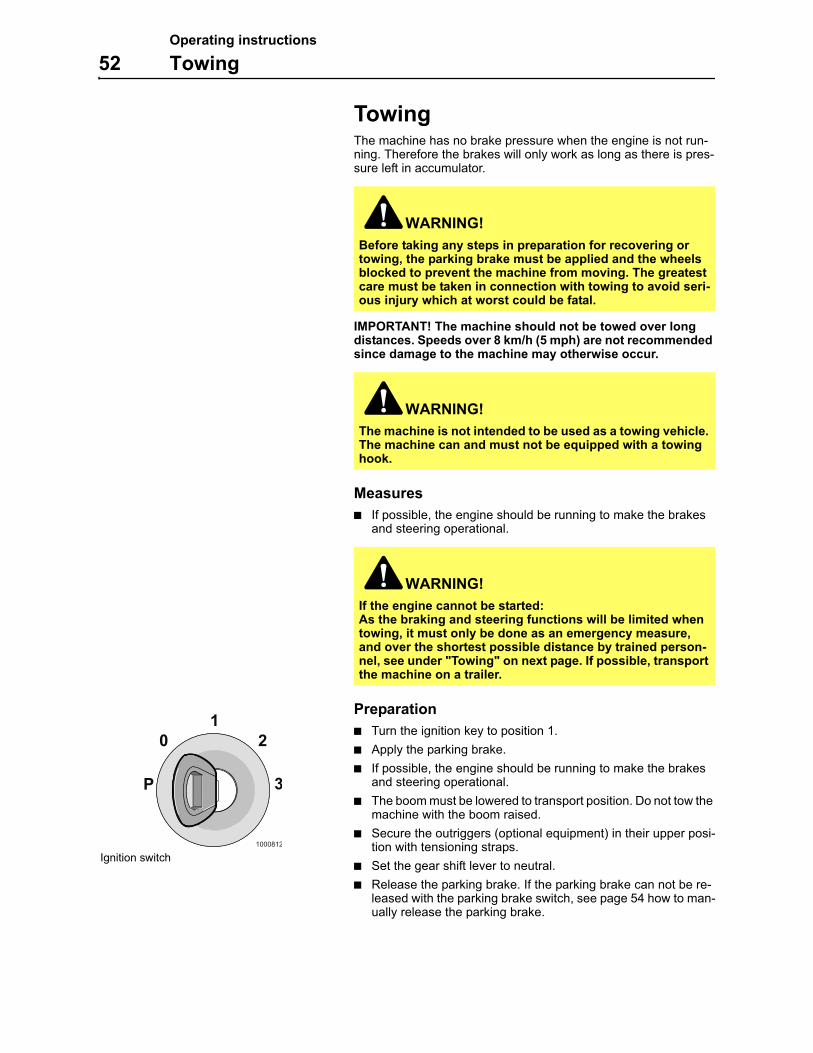
Turn the ignition key to position 1.
Apply the parking brake.
If possible, the engine should be running to make the brakes and steering operational.
The boom must be lowered to transport position. Do not tow the machine with the boom raised.
Secure the outriggers (optional equipment) in their upper posi-tion with tensioning straps.
Set the gear shift lever to neutral.
Release the parking brake. If the parking brake can not be re-leased with the parking brake switch, see page 54 how to man-ually release the parking brake.
WARNING!
Before taking any steps in preparation for recovering or towing, the parking brake must be applied and the wheels blocked to prevent the machine from moving. The greatest care must be taken in connection with towing to avoid seri-ous injury which at worst could be fatal.
WARNING!
The machine is not intended to be used as a towing vehicle. The machine can and must not be equipped with a towing hook.
WARNING!
If the engine cannot be started:As the braking and steering functions will be limited when towing, it must only be done as an emergency measure, and over the shortest possible distance by trained person-nel, see under "Towing" on next page. If possible, transport the machine on a trailer.
1000812
1
P 3
20
Ignition switch
Operating instructions
Towing 53
Towing
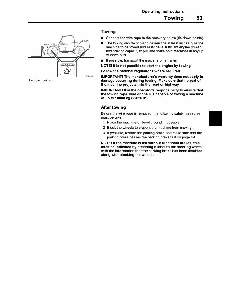
Connect the wire rope to the recovery points (tie down points).
The towing vehicle or machine must be at least as heavy as the machine to be towed and must have sufficient engine power and braking capacity to pull and brake both machines in any up or down hills.
If possible, transport the machine on a trailer.
NOTE! It is not possible to start the engine by towing.
Follow the national regulations where required.
IMPORTANT! The manufacturer's warranty does not apply to damage occurring during towing. Make sure that no part of the machine projects into the road or highway.
IMPORTANT! It is the operator’s responsibility to ensure that the towing rope, wire or chain is capable of towing a machine of up to 10000 kg (22050 Ib).
After towing
Before the wire rope is removed, the following safety measures must be taken:
1 Place the machine on level ground, if possible.
2 Block the wheels to prevent the machine from moving.
3 If possible, restore the parking brake and make sure that the parking brake passes the parking brake test on page 49.
NOTE! If the machine is left without functional brakes, this must be indicated by attaching a label to the steering wheel with the information that the parking brake has been disabled, along with blocking the wheels.
1008484
Tie down points
Operating instructions
54 Towing
Parking brake, manual release
Manually releasing the electronic parking brake must only be done when the machine has to be towed. Immediately after towing has been completed, the parking brake must be restored.
NOTE! If the machine is left without having restored the parking brake, this must be indicated by attaching a label to the steering wheel with the information that the parking brake has been disa-bled, along with blocking the wheels.
Release and restore the parking brake
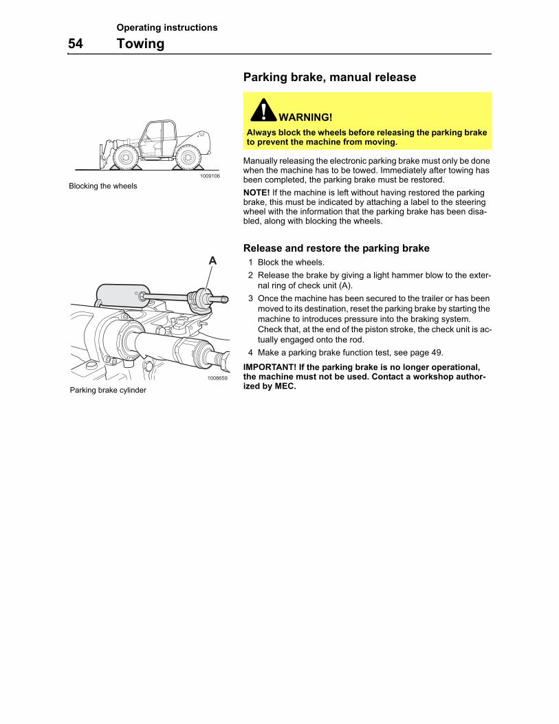
1 Block the wheels.
2 Release the brake by giving a light hammer blow to the exter-nal ring of check unit (A).
3 Once the machine has been secured to the trailer or has been moved to its destination, reset the parking brake by starting the machine to introduces pressure into the braking system. Check that, at the end of the piston stroke, the check unit is ac-tually engaged onto the rod.
4 Make a parking brake function test, see page 49.
IMPORTANT! If the parking brake is no longer operational, the machine must not be used. Contact a workshop author-ized by MEC.
WARNING!
Always block the wheels before releasing the parking brake to prevent the machine from moving.
1009106
Blocking the wheels
1008659
A
Parking brake cylinder
Operating instructions
Boom, manual lowering 55
Boom, manual loweringLowering of the boom is hydraulically controlled. If hydraulic power is lost, it is possible to lower the boom manually.
IMPORTANT! Lowering of the boom should only be done manually in case of failure on the machine/equipment.
1 Secure the risk zone around the machine from unauthorized persons.
2 Remove load and secure the machine.
3 Block the wheels.
4 Support the boom with a suitable stand or packing.
5 Open the hatch on the back of the machine.
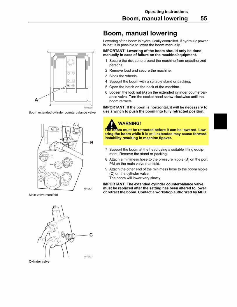
6 Loosen the lock nut (A) on the extended cylinder counterbal-ance valve. Turn the socket head screw clockwise until the boom retracts.
IMPORTANT! If the boon is horizontal, it will be necessary to use a winch to push the boom into fully retracted position.
7 Support the boom at the head using a suitable lifting equip-ment. Remove the stand or packing.
8 Attach a minimess hose to the pressure nipple (B) on the port PM on the main valve manifold.
9 Attach the other end of the minimess hose to the boom nipple (C) on the cylinder valve.The boom will lower very slowly.
IMPORTANT! The extended cylinder counterbalance valve must be replaced after the setting has been altered to lower or retract the boom. Contact a workshop authorized by MEC.
WARNING!
The boom must be retracted before it can be lowered. Low-ering the boom while it is still extended may cause forward instability resulting in machine tipover.
1009998
A
Boom extended cylinder counterbalance valve
B
LSOLSM
1010171
Main valve manifold
1010137
C
Cylinder valve
Operating instructions
56 Transporting the machine
Transporting the machine
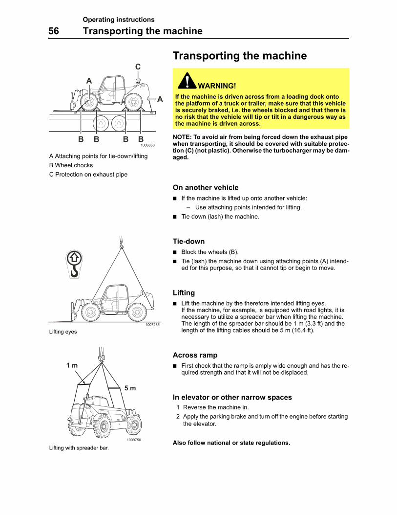
NOTE: To avoid air from being forced down the exhaust pipe when transporting, it should be covered with suitable protec-tion (C) (not plastic). Otherwise the turbocharger may be dam-aged.
On another vehicle
If the machine is lifted up onto another vehicle:
– Use attaching points intended for lifting.
Tie down (lash) the machine.
Tie-down
Block the wheels (B).
Tie (lash) the machine down using attaching points (A) intend-ed for this purpose, so that it cannot tip or begin to move.
Lifting
Lift the machine by the therefore intended lifting eyes.If the machine, for example, is equipped with road lights, it is necessary to utilize a spreader bar when lifting the machine. The length of the spreader bar should be 1 m (3.3 ft) and the length of the lifting cables should be 5 m (16.4 ft).
Across ramp
First check that the ramp is amply wide enough and has the re-quired strength and that it will not be displaced.
In elevator or other narrow spaces
1 Reverse the machine in.
2 Apply the parking brake and turn off the engine before starting the elevator.
Also follow national or state regulations.
WARNING!
If the machine is driven across from a loading dock onto the platform of a truck or trailer, make sure that this vehicle is securely braked, i.e. the wheels blocked and that there is no risk that the vehicle will tip or tilt in a dangerous way as the machine is driven across.
1006868
C
BB
A
A
B B
A Attaching points for tie-down/lifting
B Wheel chocks
C Protection on exhaust pipe
1007286
4898495
L67514A
Lifting eyes
1009750
1 m
5 m
Lifting with spreader bar.
Operating techniques
57
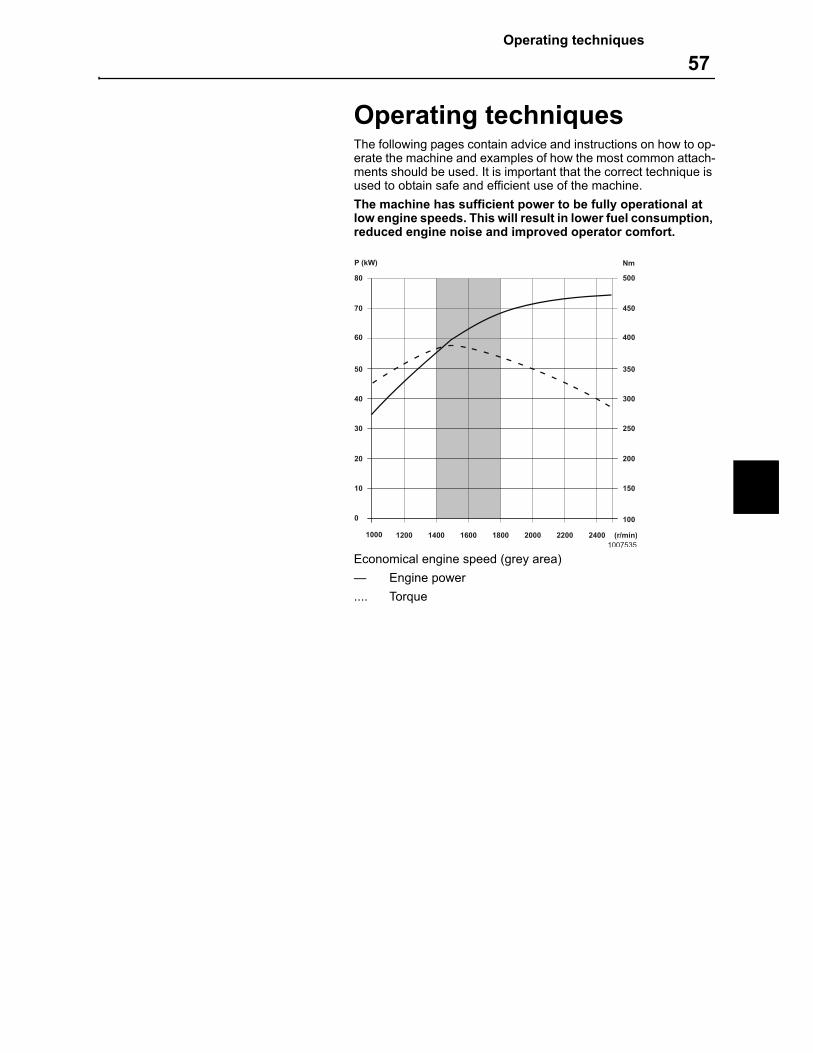
Operating techniquesThe following pages contain advice and instructions on how to op-erate the machine and examples of how the most common attach-ments should be used. It is important that the correct technique is used to obtain safe and efficient use of the machine.
The machine has sufficient power to be fully operational at low engine speeds. This will result in lower fuel consumption, reduced engine noise and improved operator comfort.
Economical engine speed (grey area)
— Engine power
.... Torque
1000 1200 1400 1600 1800 2000 2200 2400
0
10
20
30
40
50
60
70
80
P (kW)
(r/min)
100
150
200
250
300
350
400
450
500
Nm
1007535
Operating techniques
58 Attachments
AttachmentsUsing the correct attachment for a particular job is a deciding factor when it comes to the capacity of the machine.
IMPORTANT! Only use attachments approved by MEC.
The machine has either direct-mounted attachment or attachment mounted in an attachment bracket which allows rapid changes of attachment.
When choosing attachment, follow the recommendations in the At-tachment catalogue or documents issued by MEC. Because of great variations in for example usage, material and working envi-ronment, deviations from these recommendations may be neces-sary. In such cases, the MEC dealer should first be contacted for further information and approval. The operator is responsible for the safety regarding the combination of machine and attach-ment and also that the national safety requirements are met.
IMPORTANT! Never use an attachment with broken cou-plings or hoses.
WARNING!
Do not fit the machine with any form of personal work plat-form. Failure to comply may result in serious injury or death.
WARNING!
Always use the appropriate load chart when using load car-rying attachments on the machine.
WARNING!
Never use an attachment until you have checked that it is securely fastened and that the attachment including hydraulic hoses, connections and similar are undamaged – your and others safety is involved.
WARNING!
Check that the attachment is properly locked by pressing its outer edge against the ground.
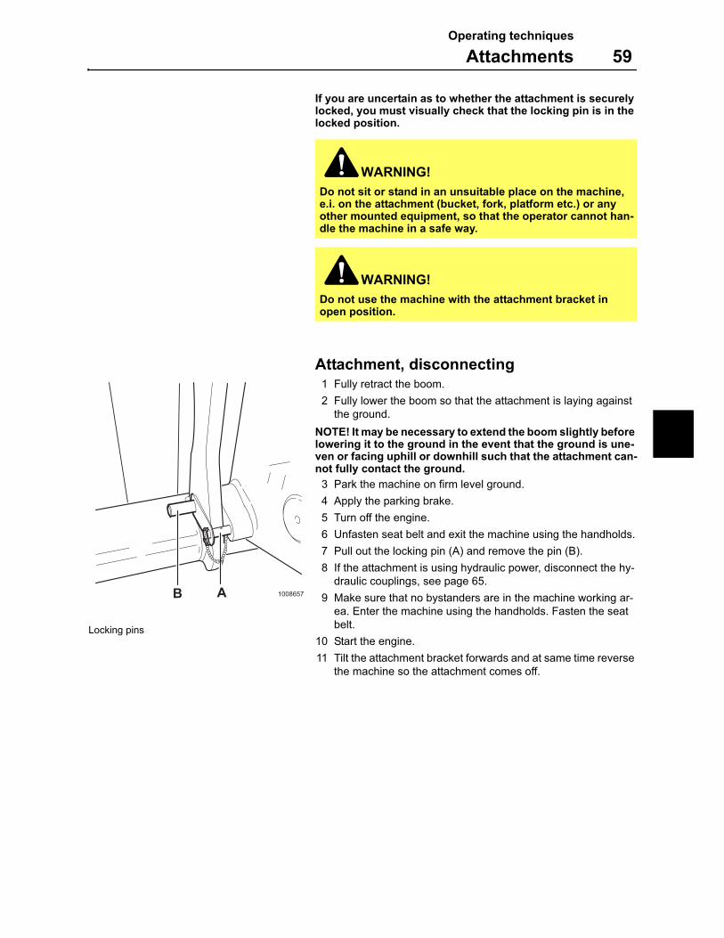
Operating techniques
Attachments 59
If you are uncertain as to whether the attachment is securely locked, you must visually check that the locking pin is in the locked position.
Attachment, disconnecting1 Fully retract the boom.
2 Fully lower the boom so that the attachment is laying against the ground.
NOTE! It may be necessary to extend the boom slightly before lowering it to the ground in the event that the ground is une-ven or facing uphill or downhill such that the attachment can-not fully contact the ground.
3 Park the machine on firm level ground.
4 Apply the parking brake.
5 Turn off the engine.
6 Unfasten seat belt and exit the machine using the handholds.
7 Pull out the locking pin (A) and remove the pin (B).
8 If the attachment is using hydraulic power, disconnect the hy-draulic couplings, see page 65.
9 Make sure that no bystanders are in the machine working ar-ea. Enter the machine using the handholds. Fasten the seat belt.
10 Start the engine.
11 Tilt the attachment bracket forwards and at same time reverse the machine so the attachment comes off.
WARNING!
Do not sit or stand in an unsuitable place on the machine, e.i. on the attachment (bucket, fork, platform etc.) or any other mounted equipment, so that the operator cannot han-dle the machine in a safe way.
WARNING!
Do not use the machine with the attachment bracket in open position.
1008657B A
Locking pins
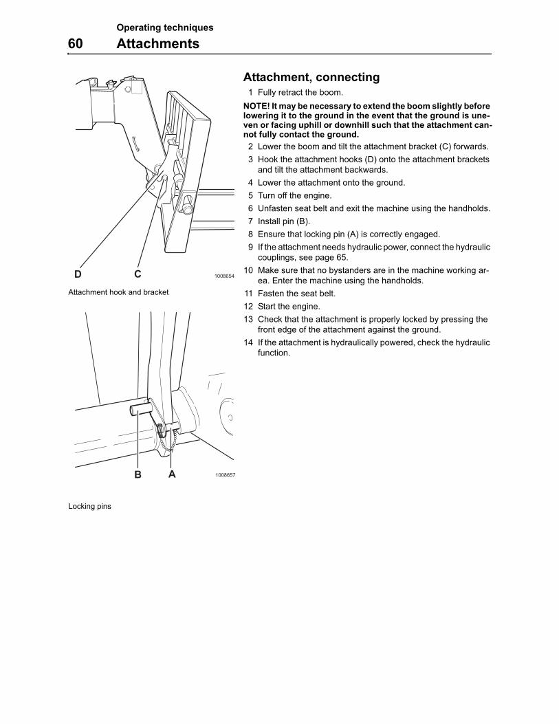
Operating techniques
60 Attachments
Attachment, connecting1 Fully retract the boom.
NOTE! It may be necessary to extend the boom slightly before lowering it to the ground in the event that the ground is une-ven or facing uphill or downhill such that the attachment can-not fully contact the ground.
2 Lower the boom and tilt the attachment bracket (C) forwards.
3 Hook the attachment hooks (D) onto the attachment brackets and tilt the attachment backwards.
4 Lower the attachment onto the ground.
5 Turn off the engine.
6 Unfasten seat belt and exit the machine using the handholds.
7 Install pin (B).
8 Ensure that locking pin (A) is correctly engaged.
9 If the attachment needs hydraulic power, connect the hydraulic couplings, see page 65.
10 Make sure that no bystanders are in the machine working ar-ea. Enter the machine using the handholds.
11 Fasten the seat belt.
12 Start the engine.
13 Check that the attachment is properly locked by pressing the front edge of the attachment against the ground.
14 If the attachment is hydraulically powered, check the hydraulic function.
1008657B A
Locking pins
1008654CDAttachment hook and bracket
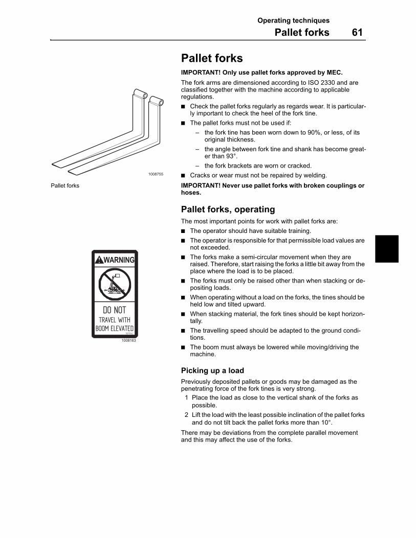
Operating techniques
Pallet forks 61
Pallet forksIMPORTANT! Only use pallet forks approved by MEC.
The fork arms are dimensioned according to ISO 2330 and are classified together with the machine according to applicable regulations.
Check the pallet forks regularly as regards wear. It is particular-ly important to check the heel of the fork tine.
The pallet forks must not be used if:
– the fork tine has been worn down to 90%, or less, of its original thickness.
– the angle between fork tine and shank has become great-er than 93°.
– the fork brackets are worn or cracked.
Cracks or wear must not be repaired by welding.
IMPORTANT! Never use pallet forks with broken couplings or hoses.
Pallet forks, operating
The most important points for work with pallet forks are:
The operator should have suitable training.
The operator is responsible for that permissible load values are not exceeded.
The forks make a semi-circular movement when they are raised. Therefore, start raising the forks a little bit away from the place where the load is to be placed.
The forks must only be raised other than when stacking or de-positing loads.
When operating without a load on the forks, the tines should be held low and tilted upward.
When stacking material, the fork tines should be kept horizon-tally.
The travelling speed should be adapted to the ground condi-tions.
The boom must always be lowered while moving/driving the machine.
Picking up a load
Previously deposited pallets or goods may be damaged as the penetrating force of the fork tines is very strong.
1 Place the load as close to the vertical shank of the forks as possible.
2 Lift the load with the least possible inclination of the pallet forks and do not tilt back the pallet forks more than 10°.
There may be deviations from the complete parallel movement and this may affect the use of the forks.
1008755
Pallet forks
DO NOTTRAVEL WITH
BOOM ELEVATED
WARNING
11870562
1008163
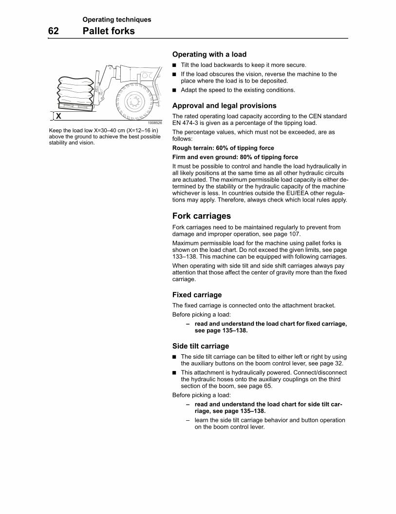
Operating techniques
62 Pallet forks
Operating with a load
Tilt the load backwards to keep it more secure.
If the load obscures the vision, reverse the machine to the place where the load is to be deposited.
Adapt the speed to the existing conditions.
Approval and legal provisions
The rated operating load capacity according to the CEN standard EN 474-3 is given as a percentage of the tipping load.
The percentage values, which must not be exceeded, are as follows:
Rough terrain: 60% of tipping force
Firm and even ground: 80% of tipping force
It must be possible to control and handle the load hydraulically in all likely positions at the same time as all other hydraulic circuits are actuated. The maximum permissible load capacity is either de-termined by the stability or the hydraulic capacity of the machine whichever is less. In countries outside the EU/EEA other regula-tions may apply. Therefore, always check which local rules apply.
Fork carriages
Fork carriages need to be maintained regularly to prevent from damage and improper operation, see page 107.
Maximum permissible load for the machine using pallet forks is shown on the load chart. Do not exceed the given limits, see page 133–138. This machine can be equipped with following carriages.
When operating with side tilt and side shift carriages always pay attention that those affect the center of gravity more than the fixed carriage.
Fixed carriage
The fixed carriage is connected onto the attachment bracket.
Before picking a load:
– read and understand the load chart for fixed carriage, see page 135–138.
Side tilt carriage
The side tilt carriage can be tilted to either left or right by using the auxiliary buttons on the boom control lever, see page 32.
This attachment is hydraulically powered. Connect/disconnect the hydraulic hoses onto the auxiliary couplings on the third section of the boom, see page 65.
Before picking a load:
– read and understand the load chart for side tilt car-riage, see page 135–138.
– learn the side tilt carriage behavior and button operation on the boom control lever.
1008526
XKeep the load low X=30–40 cm (X=12–16 in) above the ground to achieve the best possible stability and vision.

Operating techniques
Pallet forks 63
Side shift carriage
The side shift carriage can be shifted to either left or right by us-ing the auxiliary buttons on the boom control lever, see page 32.
This attachment is hydraulically powered. Connect/disconnect the hydraulic hoses onto the auxiliary couplings on the third section of the boom, see page 65.
Before picking a load:
– read and understand the load chart for side swing car-riage, see page 135–138.
– learn the side tilt carriage behavior and button operation on the boom control lever.
Operating techniques
64 Accumulator
AccumulatorThe machine is fitted with a brake accumulator, located on side of the Cab/Open ROPS.
IMPORTANT! Do not carry out any jobs on the accumulator. Contact a workshop authorized by MEC for advice.
WARNING!
Even if the engine has been stopped, there is still an accu-mulated pressure in the system. If the system is opened, without having first released the pressure, oil under high pressure will jet out and this could cause injuries.Even retightening of leaking couplings and unions should not be done until the pressure in the system has been fully released.
L66320A
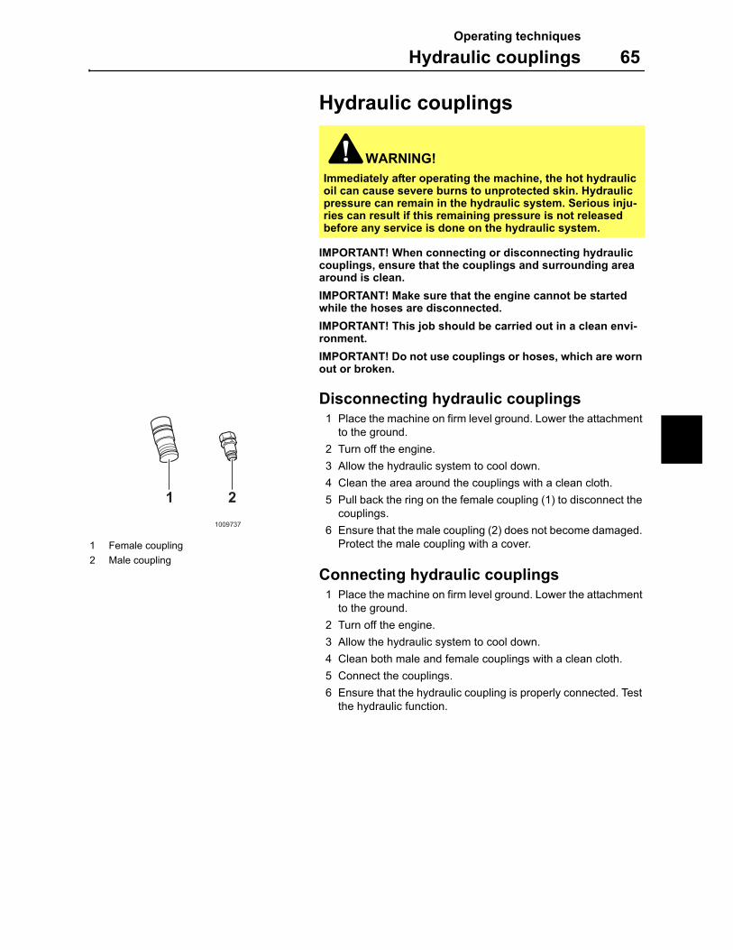
Operating techniques
Hydraulic couplings 65
Hydraulic couplings
IMPORTANT! When connecting or disconnecting hydraulic couplings, ensure that the couplings and surrounding area around is clean.
IMPORTANT! Make sure that the engine cannot be started while the hoses are disconnected.
IMPORTANT! This job should be carried out in a clean envi-ronment.
IMPORTANT! Do not use couplings or hoses, which are worn out or broken.
Disconnecting hydraulic couplings1 Place the machine on firm level ground. Lower the attachment
to the ground.
2 Turn off the engine.
3 Allow the hydraulic system to cool down.
4 Clean the area around the couplings with a clean cloth.
5 Pull back the ring on the female coupling (1) to disconnect the couplings.
6 Ensure that the male coupling (2) does not become damaged. Protect the male coupling with a cover.
Connecting hydraulic couplings1 Place the machine on firm level ground. Lower the attachment
to the ground.
2 Turn off the engine.
3 Allow the hydraulic system to cool down.
4 Clean both male and female couplings with a clean cloth.
5 Connect the couplings.
6 Ensure that the hydraulic coupling is properly connected. Test the hydraulic function.
WARNING!
Immediately after operating the machine, the hot hydraulic oil can cause severe burns to unprotected skin. Hydraulic pressure can remain in the hydraulic system. Serious inju-ries can result if this remaining pressure is not released before any service is done on the hydraulic system.
1 21009737
1 Female coupling
2 Male coupling
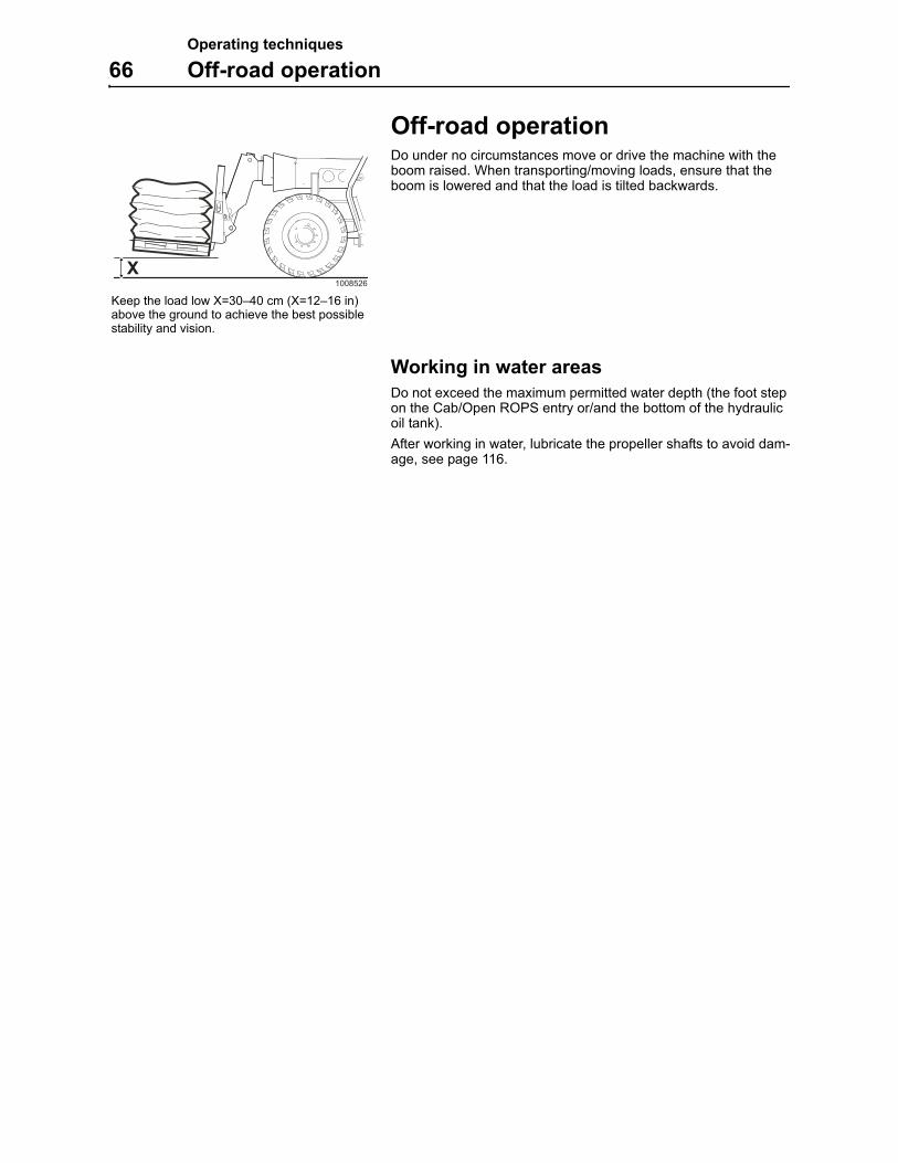
Operating techniques
66 Off-road operation
Off-road operationDo under no circumstances move or drive the machine with the boom raised. When transporting/moving loads, ensure that the boom is lowered and that the load is tilted backwards.
Working in water areas
Do not exceed the maximum permitted water depth (the foot step on the Cab/Open ROPS entry or/and the bottom of the hydraulic oil tank).
After working in water, lubricate the propeller shafts to avoid dam-age, see page 116.
1008526
XKeep the load low X=30–40 cm (X=12–16 in) above the ground to achieve the best possible stability and vision.
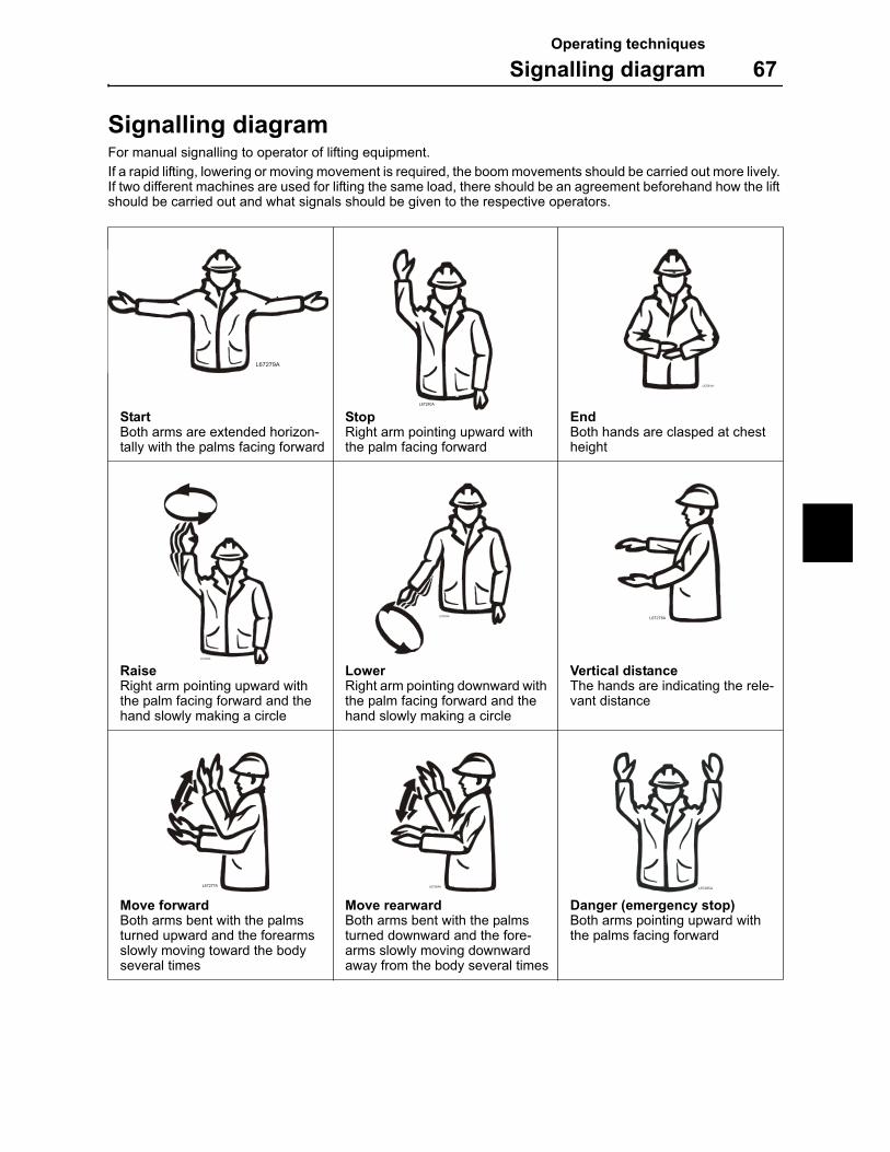
Operating techniques
Signalling diagram 67
Signalling diagramFor manual signalling to operator of lifting equipment.
If a rapid lifting, lowering or moving movement is required, the boom movements should be carried out more lively. If two different machines are used for lifting the same load, there should be an agreement beforehand how the lift should be carried out and what signals should be given to the respective operators.
StartBoth arms are extended horizon-tally with the palms facing forward
StopRight arm pointing upward with the palm facing forward
EndBoth hands are clasped at chest height
RaiseRight arm pointing upward with the palm facing forward and the hand slowly making a circle
LowerRight arm pointing downward with the palm facing forward and the hand slowly making a circle
Vertical distanceThe hands are indicating the rele-vant distance
Move forwardBoth arms bent with the palms turned upward and the forearms slowly moving toward the body several times
Move rearwardBoth arms bent with the palms turned downward and the fore-arms slowly moving downward away from the body several times
Danger (emergency stop)Both arms pointing upward with the palms facing forward
L67279A
L67280A
L67281A1
L67282A
L67283AL67278A
L67277A L67284A L67285A
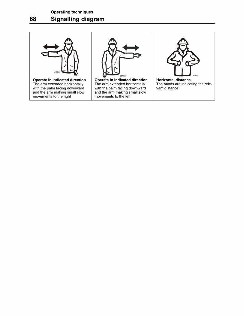
Operating techniques
68 Signalling diagram
Operate in indicated directionThe arm extended horizontally with the palm facing downward and the arm making small slow movements to the right
Operate in indicated directionThe arm extended horizontally with the palm facing downward and the arm making small slow movements to the left
Horizontal distanceThe hands are indicating the rele-vant distance
L67286A
L67287AL67288A
Safety when servicing
Service positions 69
Safety when servicingThis section deals with the safety rules which must be followed when checking and servicing the machine. MEC disclaim all responsibility if other tools, lifting devices or working methods are used than those described in this publication.
Further safety rules and warning texts are given within the respec-tive sections.
Service positionsBEFORE you begin service work the machine must be placed in any of the service positions described. See specific service job for which service position which should be used.
NOTE: Lifting with a jack must only be carried out by trained personnel.
WARNING!
If work has to be carried out on the machine before it has cooled, there is risk of burns. Therefore, take care when working with hot liquids and machine parts.
L68293A
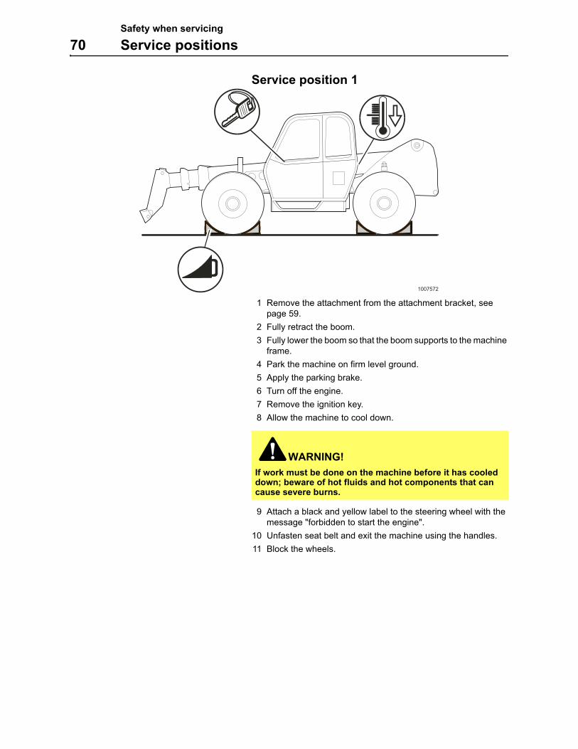
Safety when servicing
70 Service positions
Service position 1
1 Remove the attachment from the attachment bracket, see page 59.
2 Fully retract the boom.
3 Fully lower the boom so that the boom supports to the machine frame.
4 Park the machine on firm level ground.
5 Apply the parking brake.
6 Turn off the engine.
7 Remove the ignition key.
8 Allow the machine to cool down.
9 Attach a black and yellow label to the steering wheel with the message "forbidden to start the engine".
10 Unfasten seat belt and exit the machine using the handles.
11 Block the wheels.
WARNING!
If work must be done on the machine before it has cooled down; beware of hot fluids and hot components that can cause severe burns.
1007572
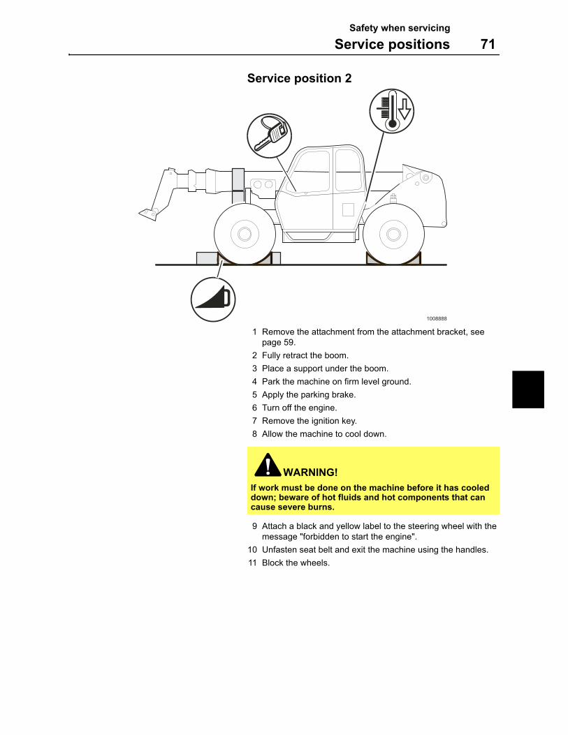
Safety when servicing
Service positions 71
Service position 2
1 Remove the attachment from the attachment bracket, see page 59.
2 Fully retract the boom.
3 Place a support under the boom.
4 Park the machine on firm level ground.
5 Apply the parking brake.
6 Turn off the engine.
7 Remove the ignition key.
8 Allow the machine to cool down.
9 Attach a black and yellow label to the steering wheel with the message "forbidden to start the engine".
10 Unfasten seat belt and exit the machine using the handles.
11 Block the wheels.
WARNING!
If work must be done on the machine before it has cooled down; beware of hot fluids and hot components that can cause severe burns.
1008888
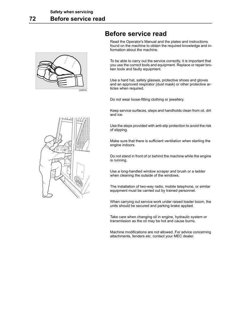
Safety when servicing
72 Before service read
Before service read Read the Operator's Manual and the plates and instructions
found on the machine to obtain the required knowledge and in-formation about the machine.
To be able to carry out the service correctly, it is important that you use the correct tools and equipment. Replace or repair bro-ken tools and faulty equipment.
Use a hard hat, safety glasses, protective shoes and gloves and an approved respirator (dust mask) or other protective ar-ticles when required.
Do not wear loose-fitting clothing or jewellery.
Keep service surfaces, steps and handholds clean from oil, dirt and ice.
Use the steps provided with anti-slip protection to avoid the risk of slipping.
Make sure that there is sufficient ventilation when starting the engine indoors.
Do not stand in front of or behind the machine while the engine is running.
Use a long-handled window scraper and brush or a ladder when cleaning the outside of the windows.
The installation of two-way radio, mobile telephone, or similar equipment must be carried out by trained personnel.
When carrying out service work under raised loader boom, the units should be secured and parking brake applied.
Take care when changing oil in engine, hydraulic system or transmission as the oil may be hot and cause burns.
Machine modifications are not allowed. For advice concerning attachments, fenders etc. contact your MEC dealer.
L64527A
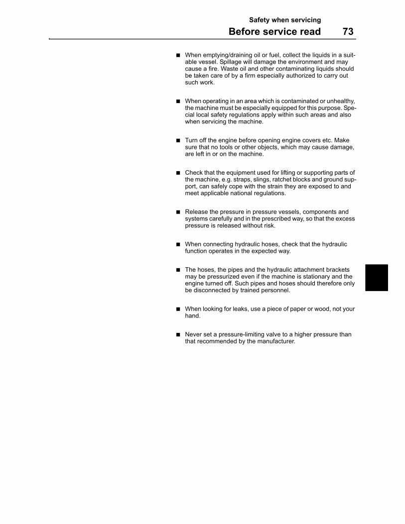
Safety when servicing
Before service read 73
When emptying/draining oil or fuel, collect the liquids in a suit-able vessel. Spillage will damage the environment and may cause a fire. Waste oil and other contaminating liquids should be taken care of by a firm especially authorized to carry out such work.
When operating in an area which is contaminated or unhealthy, the machine must be especially equipped for this purpose. Spe-cial local safety regulations apply within such areas and also when servicing the machine.
Turn off the engine before opening engine covers etc. Make sure that no tools or other objects, which may cause damage, are left in or on the machine.
Check that the equipment used for lifting or supporting parts of the machine, e.g. straps, slings, ratchet blocks and ground sup-port, can safely cope with the strain they are exposed to and meet applicable national regulations.
Release the pressure in pressure vessels, components and systems carefully and in the prescribed way, so that the excess pressure is released without risk.
When connecting hydraulic hoses, check that the hydraulic function operates in the expected way.
The hoses, the pipes and the hydraulic attachment brackets may be pressurized even if the machine is stationary and the engine turned off. Such pipes and hoses should therefore only be disconnected by trained personnel.
When looking for leaks, use a piece of paper or wood, not your hand.
Never set a pressure-limiting valve to a higher pressure than that recommended by the manufacturer.
Safety when servicing
74 Before service read
Fire prevention measures
There is always a risk of fire. It is important that you use a fire ex-tinguisher that suits your machine and working environment and that you learn how to use it.
If the machine is to be provided with a hand-held fire extinguisher, it should be of the ABE type (ABC in the USA), which means that it is possible to extinguish fires in both solid and liquid carbona-ceous material and that the active compound does not conduct electricity.
The effectiveness grade I means that the time the extinguisher is effective must not be less that 8 seconds, grade II at least 11 sec-onds and grade III at least 15 seconds.
A hand-held fire extinguisher ABE I (in the USA ABC type) normal-ly corresponds to a powder content of 4 kg (EN-grade 13A89BC), standard EN 3-1995, parts 1, 2, 4 and 5.
At the slightest sign of fire, and if the situation allows, take the fol-lowing steps:
1 Drive the machine away from the fire-sensitive area caused by the fire.
2 Lower the boom to the ground.
3 Turn off the engine.
4 Leave the cab.
5 Turn off the battery disconnect switch.
6 Start putting out the fire and notify the fire brigade/department if necessary.
It is forbidden to smoke or have an open flame near a machine when filling with fuel or when the fuel system is open and in contact with the surrounding air.
Diesel fuel oil is flammable and must not be used for cleaning. Use an approved solvent and do not inhale the fumes. Also bear in mind that certain solvents can cause skin rashes and constitute a fire hazard.
Store flammable starting aids in cool, well ventilated locations. These aids must not be used in connection with electric pre-heating of the induction air.
Keep the place, where the service is to be carried out, clean. Oil or water makes the floor slippery and are also dangerous in connection with electrical equipment or electrically powered tools. Oily or greasy clothes are a serious fire hazard.
Check daily that the machine and the equipment, e.g. under body plates are free from dust and oil. In this way the risk of fire is reduced and it is easier to detect faulty or loose components.
If a high-pressure jet is used for cleaning, take great care as the insulation of electric leads can be damaged even at a moderately high pressure and temperature. Protect electrical leads in an appropriate way.
Safety when servicing
Before service read 75
Take extra care when cleaning the machine after it has been used in a fire-sensitive environment, e.g. saw-mills and refuse dumps.
Sound absorbing material in the engine compartment must be kept clean to minimise the fire hazard.
Fire prevention equipment which is installed on the machine must be maintained and regarded as a complement to the ac-tions of the operator in case of a fire. Check that fuel lines, hydraulic and brake hoses and electrical cables have not been damaged by chafing or are not in danger of being damaged in that way because of incorrect installation or clamping. This applies particularly to unfused cables, which are red and marked R (B+) and routed:
– between the batteries
– between battery and starter motor
– between alternator and starter motor
– to the preheating element on the engine
Electrical cables must not lie directly against oil or fuel lines.
The following applies for welding and grinding work:
– A fire extinguisher should be kept near to hand.
– The ventilation must be good when working indoors.
– Approved respirator should be used
– The work surface must be cleaned.
– Do not weld or grind on components which are filled with flammable liquids, e.g. tanks and hydraulic pipes. Exer-cise care with such work also in the proximity of such plac-es.
Safety when servicing
76 Before service read
Working on painted surfaces
When welding, grinding and gas cutting, the paint finish must first be removed from an area with a radius of at least 10 cm (4 in) from the point where the work is to be carried out. The reason for this is that paint, when heated, gives off a large number of different sub-stances which can cause irritation and be very harmful to a per-son's health in case of long or frequent exposure.
In addition to the health hazard, the weld will also be of inferior quality and strength, which in the future may cause the weld to break. Therefore, never weld directly on a painted surface.
Methods and precautionary measures when removing paint:
Blasting
– use respirator and eye protection
Paint remover or other chemicals
– use a portable air extractor, respirator and protective gloves
Grinding machine
– use a portable air extractor, respirator and protective gloves and eye protection
Fluoro-carbon rubber
Observe extra great care when it is suspected that you may have to handle fluoro-carbon rubber.
Certain seals which have to withstand high operating temperatures (e.g. in engines, hydraulic pumps) may be made from fluoro-car-bon rubber, which, when exposed to strong heat (fire), forms hy-drogen fluoride and hydrofluoric acid. This acid is very corrosive and cannot be rinsed or washed off from the skin. It causes very severe burns which take a long time to heal.
It usually means that damaged tissue must be surgically removed. Several hours may pass after contact with the acid, before any symptoms appear and therefore one is not given any immediate warning. The acid may remain on the machine parts for several years after a fire.
If swelling, redness or a stinging feeling appears and one suspects that the cause may be contact with heated fluoro-carbon rubber, contact a medical doctor immediately. If a machine, or part of a ma-chine, has been exposed to fire or severe heat, it should be han-dled by specially trained personnel. In all handling of machines after a fire, thick rubber gloves and effective goggles must be used.
The area around a part which has been very hot and which may be made of fluoro-carbon rubber should be decontaminated by thor-ough and ample washing with lime water (a solution or suspension of calcium hydroxide, i.e. slaked lime in water). After the work has been completed, the gloves should be washed in lime water and then discarded.
WARNING!
Be careful when welding, grinding and gas cutting near painted surfaces and near rubber or plastic parts. Paint and polymer materials can, when heated, form compounds which are dangerous to health and environment.
Safety when servicing
Before service read 77
Rubber and plastics
Polymer materials can, when heated, form compounds which are dangerous to health and environment and must therefore never be burned when scrapped. Also take care when handling machines which have been exposed to fire or other extreme heat.
If gas cutting or welding is to be carried out near such materials, the following safety instructions must be followed:
– Protect the material from heat.
Use protective gloves, protective goggles and an approved respi-rator.
Waste hazardous to the environment
Painted parts or parts made of plastic or rubber which are to be scrapped must never be burnt, but must be taken care of by an approved refuse-handling plant.
Batteries, plastic objects and anything else which might be dan-gerous to the environment must be taken care of in an environ-mentally safe way.
Check list after fire
When handling a machine which has been damaged by fire or been exposed to intense heat, the following protective meas-ures must under all circumstances be followed:
Use thick, gloves made of rubber and wear goggles which are certain to protect your eyes.
Never touch burnt components with your bare hands, as there is a risk that you may come into contact with melted polymer materials. First wash thoroughly with plenty of lime water (a so-lution or suspension of calcium hydroxide, i.e. slaked lime in water).
As a precaution, seals (O-rings and other oil seals) should al-ways be handled as if they were made of fluoro-carbon rubber.
Treat skin, which may have come into contact with burnt fluoro-carbon rubber, with Hydrofluoric Acid Burn Jelly or some-thing similar. Seek medical advice. Symptoms may not appear until several hours afterwards.
Discard gloves, rags etc. which may have come into contact with burnt fluoro-carbon rubber.

Safety when servicing
78
Service and maintenance
79
Service and maintenanceFor the machine to function satisfactorily and at the lowest possi-ble cost, thorough maintenance is required. This section of the manual describes the maintenance work which the operator can carry out. If certain work requires trained service personnel and special equipment, this will be stated.
The intervals recommended between checks, oil changes and lu-brication apply provided that the machine is used under normal en-vironmental and operating conditions.
For service and maintenance intervals, see page 109–113.
Paintwork maintenance
Machines which are operated in corrosive environment are more exposed to rust than others. As a preventive measure, any dam-age to the paintwork should be re-painted and anti-rust agent should be applied every six month.
1 Wash the machine. If using water with high pressure, keep a certain distance between the nozzle and the machine and do not let the water temperature exceed 60 °C.
2 Let the machine dry.
3 Check if there are any damaged areas to the paintwork. If found - touch-up those.
4 Apply Dinol 77B (or equivalent) to a thickness of 70–80 μ.
5 Also apply a protective layer of underbody seal, Dinitrol 447 (or equivalent) under mudguards, where mechanical paint dam-age can be expected.
Arrival and delivery inspection
Before the machine leaves the factory, it is tested and adjusted. The dealer must also, if the warranty is to apply, carry out "Arrival and delivery inspections" according to applicable form, which must be signed.
Delivery Instructions
When handing the machine over, the dealer must give the buyer "Delivery instructions" according to applicable form, which must be signed, if the warranty is to apply.
Service programme
Warranty inspection
Two warranty inspections should be carried out if the warranties are to apply. The first within 100 hours and the second at the latest at 1000 operating hours.
The carrying out of these inspections is a condition for the warranty to apply.
Condition test
Condition Test is carried out at workshops authorized by MECand provides information about the general condition of the ma-chine.
L52168B
1 (8)
Please pay attention to the safety instruction in the Operator’s Manual and Service Manual for the
machines concerned.
See Service Guide regarding specifications and the Operator ’s Manual regarding information about controls and changes.
Machine type Ser. no. Delivery dateOperated hours
Owner Date
Sign.Dealer
SERVICE PROGRAMMESERVICE PROGRAMMESERVICE PROGRAMMESERVICE PROGRAMMEWheel LoadersExcavator-Loaders
OPERATING HOURS / HOURLY INTERVALFirst100
First1000
Daily every50
every250
every500
every1000
every2000
Notes
A = Warranty InspectionsB = Maintenance A A B B B B B B
1 General
1:1 Test-run and check.– Starting and stop functions (including any
cold-starting devices).– Instruments, lights, direction indicators,
reflectors, hazard flashers, wipers, was-hers and horn, if applicable – reversingalarm.
– Gear selector pos. / automatic gear shif-ting.
– Differential lock, if fitted.– Brake system (service brakes).– Control lamp for low brake pressure.– Parking brake.– Steering system.– Heating and ventilation, fan and controls
incl. any air conditioning.– Loader unit / excavator unit functions
incl. boom kick-out and bucket positions.– Optional equipment
1:2 Bolted joints, checking tightening torque:– Engine mounting– Transmission mounting– Axle mounting– Flanged joints, propeller shafts– Support bearing, propeller shaft– Cab mounting– Roll Over Protective Structure, ROPS,
only L330C and L330D.
1:3 Lubrication, see lubrication chart.Certain points should also be lubricatedevery 100 hours, see Operator’s Manual.
1:4 Leakage, check.
1:5 Pipes and hoses, check.
1 (2)
Delivery instruction carried out on theDELIVERY INSTRUCTIONS
Pay attention to the safety instruction in the Operator’s Instruction Manual
.Machine type Ser. no.
Owner Customer no.
Operator (Recipient).Wheel loaders /Excavator loadersArticulated haulersExcavators
Performing and signing the delivery instructions is a pre-condition for a valid machine warranty. Performed
1 Check together with the owner/operator that the delivered machine corresponds to the order.
2 Presentation of the machine including optional equipment.
Review of the Operator’s Manual with emphasis on the following points.
(Depending on machine type, certain points are omitted.) Performed
3 Operation
– Run-in instructions.
– Instruments and operating controls.
– Start-stop, warming up.
– Transmission, shifting gears.
– Retarder function.
– Service brakes and parking brake.
– Steering, secondary steering.
– Operator environment, heating, ventilation and air conditioning.
– Attachment bracket (attaching an attachment).
– Loading, digging, dumping and lifting operations.
– Operation on a public road.
– Towing.
4 Service, maintenance
Engine.
– Lubrication, cooling system and fuel system.
Electrical system.
Power transmission.
Brake system.
Compressed air system.
Hydraulic system.
Lubrication chart.
5 Safety instructions.
1 (2)
ARRIVAL AND DELIVERY
Please pay attention to the safety instructions in the Operator’s and Service Manuals concerned.
Mashine type
Dealer
Arrival inspection by
Arrival date
Delivery inspection by
Dlivery date
Ser. No. Running hours
INSPECTONWheel Loaders /Excavator LoadersArticulated HaulersExcavators
Arrival inspection Performed
1 The arrival inspection is the first check of the product after transport. Any deviations or transportdamage must be reported to the carrier, and then immediate corrective actions must be taken.
2 Check that the machine is equipped according to the order confirmation, and that tools and man-uals are supplied with the machine. Any deviations should be reported to the sales department.
3 Check that no caps for the oil filler pipe, fuel tank, radiator or expansion tank are missing.When applicable, check that the cap for the brake fluid reservoir is not missing.
4 Machines transported by ship should be hosed down with fresh water as soon as possible.
5 After the inspection, the anti-corrosion treatment of the machine should be renewed, if it is to bestored again for a longer period. Follow the instructions in "MAINTENANCE OF IN-STOCKMACHINES".
Delivery inspection Performed
6 Check the engine coolant level and the oil level in the engine, transmission and hydraulic system.When applicable, check the level in all brake fluid reservoirs.
7 Remove transport protection from the hydraulic cylinders.Clean any anti-corrosion agent from the piston rods.
8 Check and adjust the tire pressure.
9 Start the engine and run the machine until normal operating temperature has been reached.Check that the following systems function normally:– Electrical system: Check that instruments and lights work.– Brake system: Apply the service brakes and engage the retarder (optional).– Steering system: Turn the steering wheel to both left and right steering lock positions.– Hydraulic system: Run all hydraulic cylinders to their respective end position.Check the function of all equipment.
10 Check that there are no leaks.
11 Any malfunctions or defects must be corrected, noted and reported to the supervisor.See page 2.
L68941A
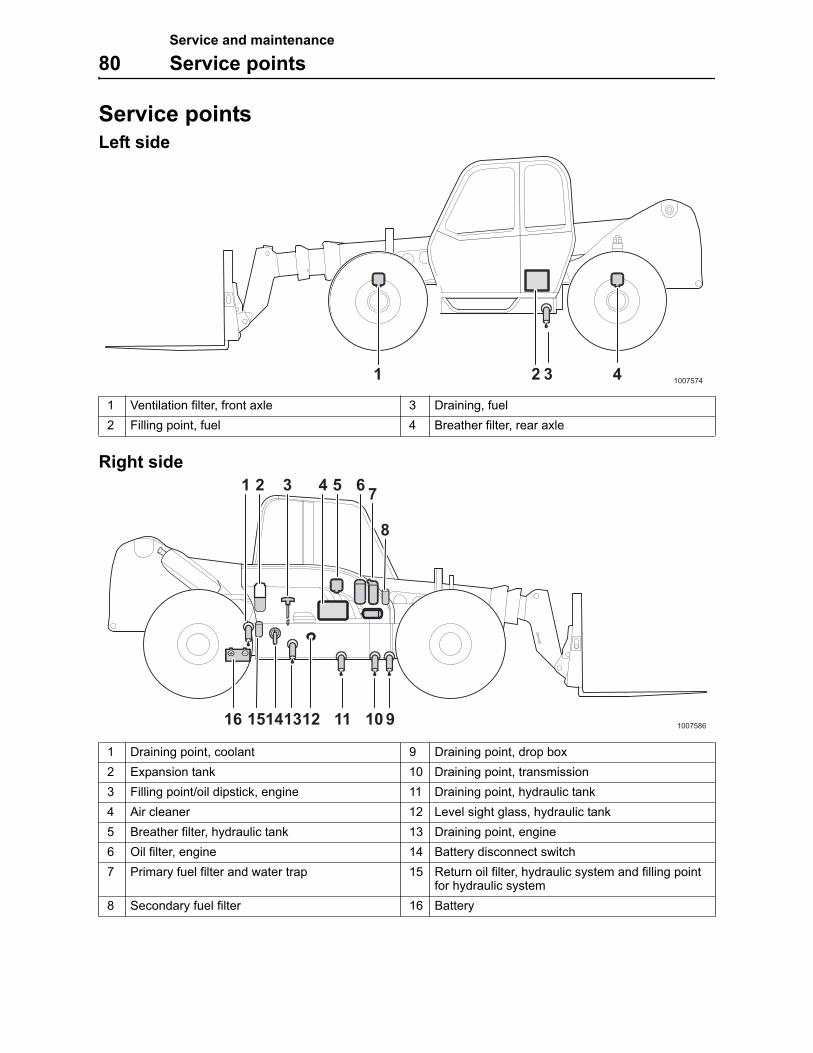
Service and maintenance
80 Service points
Service pointsLeft side
Right side
1 Ventilation filter, front axle 3 Draining, fuel
2 Filling point, fuel 4 Breather filter, rear axle
1 Draining point, coolant 9 Draining point, drop box
2 Expansion tank 10 Draining point, transmission
3 Filling point/oil dipstick, engine 11 Draining point, hydraulic tank
4 Air cleaner 12 Level sight glass, hydraulic tank
5 Breather filter, hydraulic tank 13 Draining point, engine
6 Oil filter, engine 14 Battery disconnect switch
7 Primary fuel filter and water trap 15 Return oil filter, hydraulic system and filling point for hydraulic system
8 Secondary fuel filter 16 Battery
1 2 3 41007574
100758613141516 11 10 9
8
7654
12
21 3
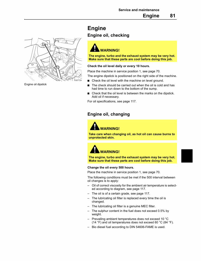
Service and maintenance
Engine 81
EngineEngine oil, checking
Check the oil level daily or every 10 hours.
Place the machine in service position 1, see page 70.
The engine dipstick is positioned on the right side of the machine.
Check the oil level with the machine on level ground.
The check should be carried out when the oil is cold and has had time to run down to the bottom of the sump.
Check that the oil level is between the marks on the dipstick. Add oil if necessary.
For oil specifications, see page 117.
Engine oil, changing
Change the oil every 500 hours.
Place the machine in service position 1, see page 70.
The following conditions must be met if the 500 interval between oil changes is to apply:
– Oil of correct viscosity for the ambient air temperature is select-ed according to diagram, see page 117.
– The oil is of a certain grade, see page 117.
– The lubricating oil filter is replaced every time the oil is changed.
– The lubricating oil filter is a genuine MEC filter.
– The sulphur content in the fuel does not exceed 0.5% by weight.
– Prevailing ambient temperatures does not exceed 10 °C (14 °F) and oil temperatures does not exceed 60 °C (84 °F).
– Bio diesel fuel according to DIN 54606-FAME is used.
WARNING!
The engine, turbo and the exhaust system may be very hot. Make sure that these parts are cool before doing this job.
WARNING!
Take care when changing oil, as hot oil can cause burns to unprotected skin.
WARNING!
The engine, turbo and the exhaust system may be very hot. Make sure that these parts are cool before doing this job.
1007724
Engine oil dipstick
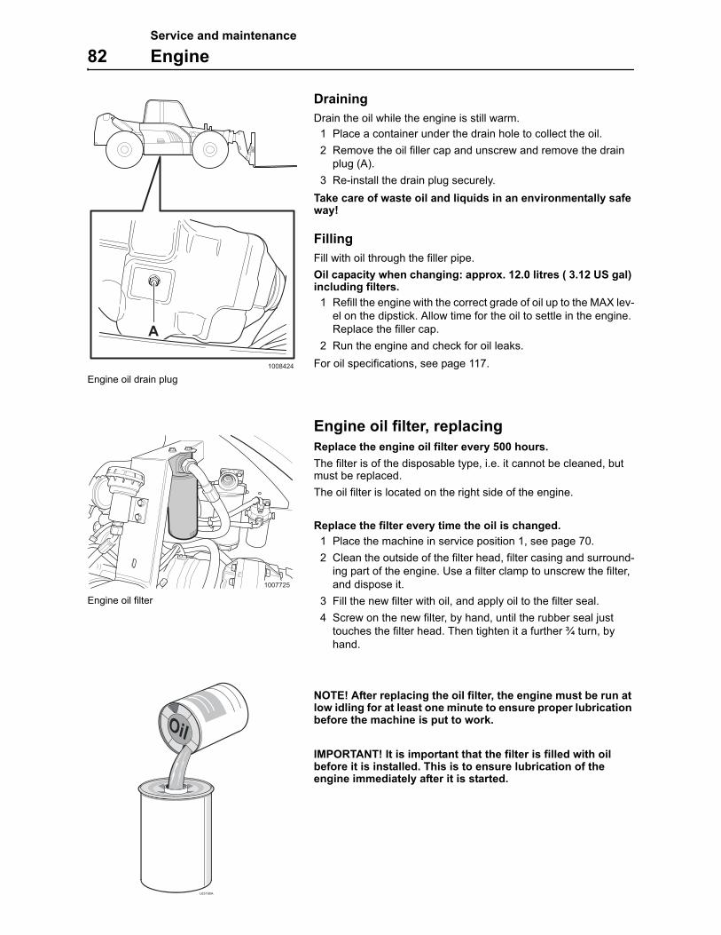
Service and maintenance
82 Engine
Draining
Drain the oil while the engine is still warm.
1 Place a container under the drain hole to collect the oil.
2 Remove the oil filler cap and unscrew and remove the drain plug (A).
3 Re-install the drain plug securely.
Take care of waste oil and liquids in an environmentally safe way!
Filling
Fill with oil through the filler pipe.
Oil capacity when changing: approx. 12.0 litres ( 3.12 US gal) including filters.
1 Refill the engine with the correct grade of oil up to the MAX lev-el on the dipstick. Allow time for the oil to settle in the engine. Replace the filler cap.
2 Run the engine and check for oil leaks.
For oil specifications, see page 117.
Engine oil filter, replacing
Replace the engine oil filter every 500 hours.
The filter is of the disposable type, i.e. it cannot be cleaned, but must be replaced.
The oil filter is located on the right side of the engine.
Replace the filter every time the oil is changed.
1 Place the machine in service position 1, see page 70.
2 Clean the outside of the filter head, filter casing and surround-ing part of the engine. Use a filter clamp to unscrew the filter, and dispose it.
3 Fill the new filter with oil, and apply oil to the filter seal.
4 Screw on the new filter, by hand, until the rubber seal just touches the filter head. Then tighten it a further ¾ turn, by hand.
NOTE! After replacing the oil filter, the engine must be run at low idling for at least one minute to ensure proper lubrication before the machine is put to work.
IMPORTANT! It is important that the filter is filled with oil before it is installed. This is to ensure lubrication of the engine immediately after it is started.
1008424
A
Engine oil drain plug
1007725
Engine oil filter
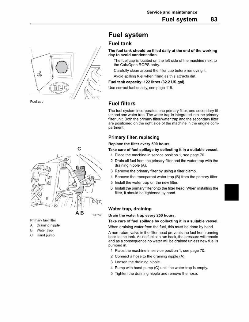
Service and maintenance
Fuel system 83
Fuel systemFuel tankThe fuel tank should be filled daily at the end of the working day to avoid condensation.
The fuel cap is located on the left side of the machine next to the Cab/Open ROPS entry.
Carefully clean around the filler cap before removing it.
Avoid spilling fuel when filling as this attracts dirt.
Fuel tank capacity: 122 litres (32.2 US gal).
Use correct fuel quality, see page 118.
Fuel filtersThe fuel system incorporates one primary filter, one secondary fil-ter and one water trap. The water trap is integrated into the primary filter unit. Both the primary filter/water trap and the secondary filter are positioned on the right side of the machine in the engine com-partment.
Primary filter, replacingReplace the filter every 500 hours.
Take care of fuel spillage by collecting it in a suitable vessel.
1 Place the machine in service position 1, see page 70.
2 Drain all fuel from the primary filter and the water trap with the draining nipple (A).
3 Remove the primary filter by using a filter clamp.
4 Remove the transparent water trap (B) from the primary filter.
5 Install the water trap on the new filter.
6 Install the primary filter onto the filter head. When installing the filter, it should be tightened by hand.
Water trap, drainingDrain the water trap every 250 hours.
Take care of fuel spillage by collecting it in a suitable vessel.
When draining water from the fuel, this must be done by hand.
A non-return valve in the filter head prevents the fuel from running back to the tank. As no fuel can run back, the pressure will remain and as a consequence no water will be drained unless new fuel is pumped in.
1 Place the machine in service position 1, see page 70.
2 Connect a hose to the draining nipple (A).
3 Loosen the draining nipple.
4 Pump with hand pump (C) until the water trap is empty.
5 Tighten the draining nipple and remove the hose.
1007701
Fuel cap
1007702A B
C
Primary fuel filter
A Draining nipple
B Water trap
C Hand pump
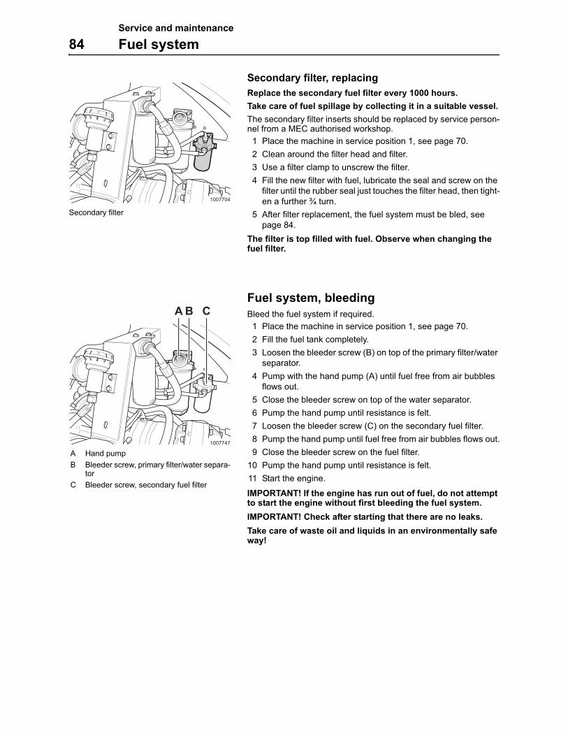
Service and maintenance
84 Fuel system
Secondary filter, replacing
Replace the secondary fuel filter every 1000 hours.
Take care of fuel spillage by collecting it in a suitable vessel.
The secondary filter inserts should be replaced by service person-nel from a MEC authorised workshop.
1 Place the machine in service position 1, see page 70.
2 Clean around the filter head and filter.
3 Use a filter clamp to unscrew the filter.
4 Fill the new filter with fuel, lubricate the seal and screw on the filter until the rubber seal just touches the filter head, then tight-en a further ¾ turn.
5 After filter replacement, the fuel system must be bled, see page 84.
The filter is top filled with fuel. Observe when changing the fuel filter.
Fuel system, bleeding
Bleed the fuel system if required.
1 Place the machine in service position 1, see page 70.
2 Fill the fuel tank completely.
3 Loosen the bleeder screw (B) on top of the primary filter/water separator.
4 Pump with the hand pump (A) until fuel free from air bubbles flows out.
5 Close the bleeder screw on top of the water separator.
6 Pump the hand pump until resistance is felt.
7 Loosen the bleeder screw (C) on the secondary fuel filter.
8 Pump the hand pump until fuel free from air bubbles flows out.
9 Close the bleeder screw on the fuel filter.
10 Pump the hand pump until resistance is felt.
11 Start the engine.
IMPORTANT! If the engine has run out of fuel, do not attempt to start the engine without first bleeding the fuel system.
IMPORTANT! Check after starting that there are no leaks.
Take care of waste oil and liquids in an environmentally safe way!
1007704
Secondary filter
1007747
BA C
A Hand pump
B Bleeder screw, primary filter/water separa-tor
C Bleeder screw, secondary fuel filter
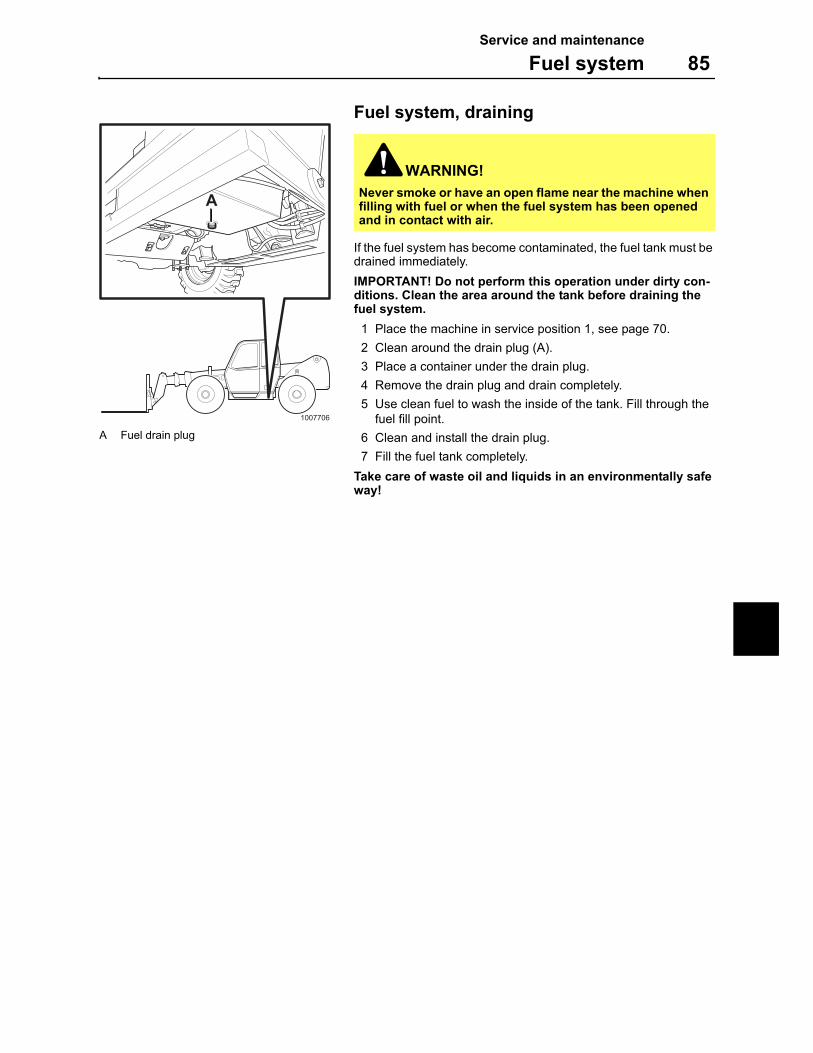
Service and maintenance
Fuel system 85
Fuel system, draining
If the fuel system has become contaminated, the fuel tank must be drained immediately.
IMPORTANT! Do not perform this operation under dirty con-ditions. Clean the area around the tank before draining the fuel system.
1 Place the machine in service position 1, see page 70.
2 Clean around the drain plug (A).
3 Place a container under the drain plug.
4 Remove the drain plug and drain completely.
5 Use clean fuel to wash the inside of the tank. Fill through the fuel fill point.
6 Clean and install the drain plug.
7 Fill the fuel tank completely.
Take care of waste oil and liquids in an environmentally safe way!
WARNING!
Never smoke or have an open flame near the machine when filling with fuel or when the fuel system has been opened and in contact with air.
1007706
A
A Fuel drain plug
Service and maintenance
86 Turbocharger
TurbochargerThe turbocharger is lubricated and cooled by the engine lubrica-tion system.
Important for the function of the turbocharger is that:
lubrication and cooling is safeguarded by
– not racing the engine immediately after it has been start-ed.
– by allowing the engine to run at low idle for a couple of minutes before it is turned off.
engine oil is changed and lubricating oil filter replaced at pre-scribed service intervals.
the air cleaner is serviced regularly and that the exhaust sys-tem and lubricating oil lines do not leak.
If jarring noises can be heard, or if the turbocharger vibrates, it must be reconditioned or replaced immediately.
Only workshops authorized by MEC should carry out work on the turbocharger.
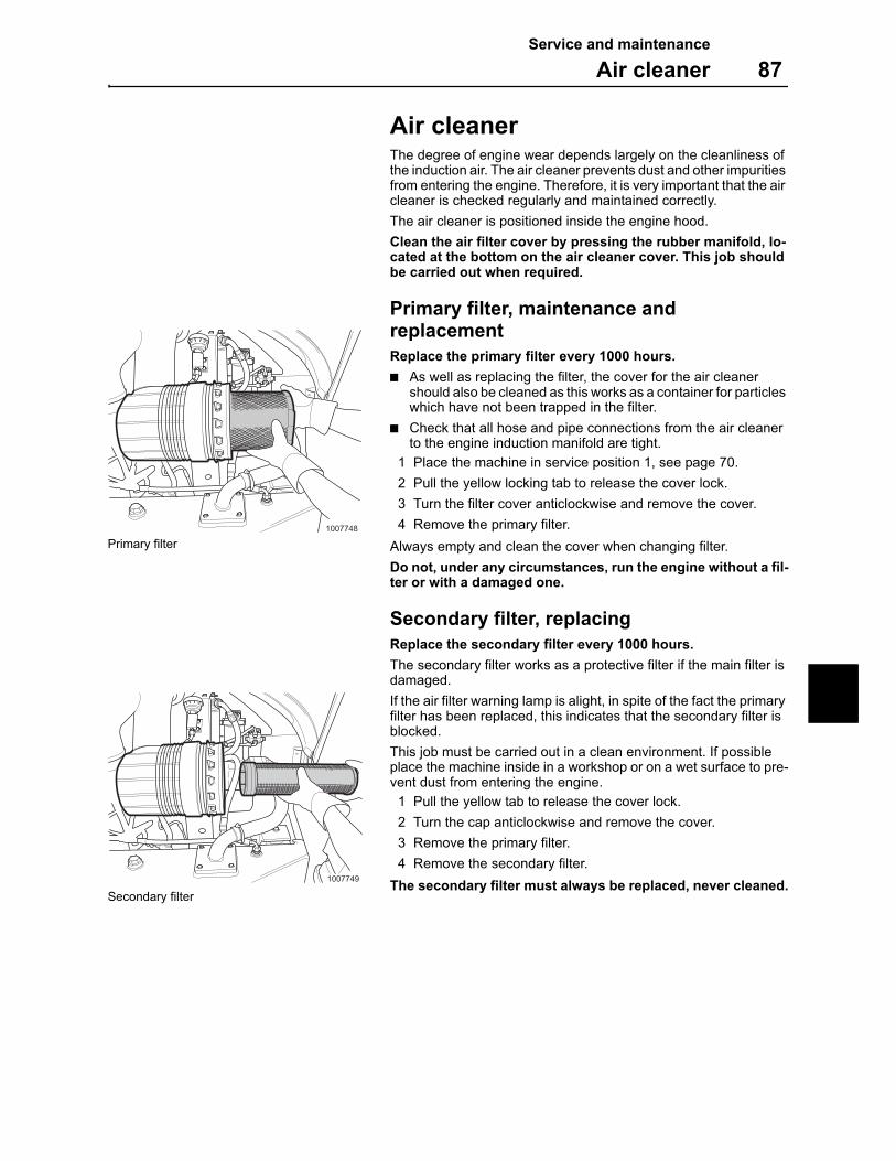
Service and maintenance
Air cleaner 87
Air cleanerThe degree of engine wear depends largely on the cleanliness of the induction air. The air cleaner prevents dust and other impurities from entering the engine. Therefore, it is very important that the air cleaner is checked regularly and maintained correctly.
The air cleaner is positioned inside the engine hood.
Clean the air filter cover by pressing the rubber manifold, lo-cated at the bottom on the air cleaner cover. This job should be carried out when required.
Primary filter, maintenance and replacement
Replace the primary filter every 1000 hours.
As well as replacing the filter, the cover for the air cleaner should also be cleaned as this works as a container for particles which have not been trapped in the filter.
Check that all hose and pipe connections from the air cleaner to the engine induction manifold are tight.
1 Place the machine in service position 1, see page 70.
2 Pull the yellow locking tab to release the cover lock.
3 Turn the filter cover anticlockwise and remove the cover.
4 Remove the primary filter.
Always empty and clean the cover when changing filter.
Do not, under any circumstances, run the engine without a fil-ter or with a damaged one.
Secondary filter, replacing
Replace the secondary filter every 1000 hours.
The secondary filter works as a protective filter if the main filter is damaged.
If the air filter warning lamp is alight, in spite of the fact the primary filter has been replaced, this indicates that the secondary filter is blocked.
This job must be carried out in a clean environment. If possible place the machine inside in a workshop or on a wet surface to pre-vent dust from entering the engine.
1 Pull the yellow tab to release the cover lock.
2 Turn the cap anticlockwise and remove the cover.
3 Remove the primary filter.
4 Remove the secondary filter.
The secondary filter must always be replaced, never cleaned.
1007748
Primary filter
1007749
Secondary filter
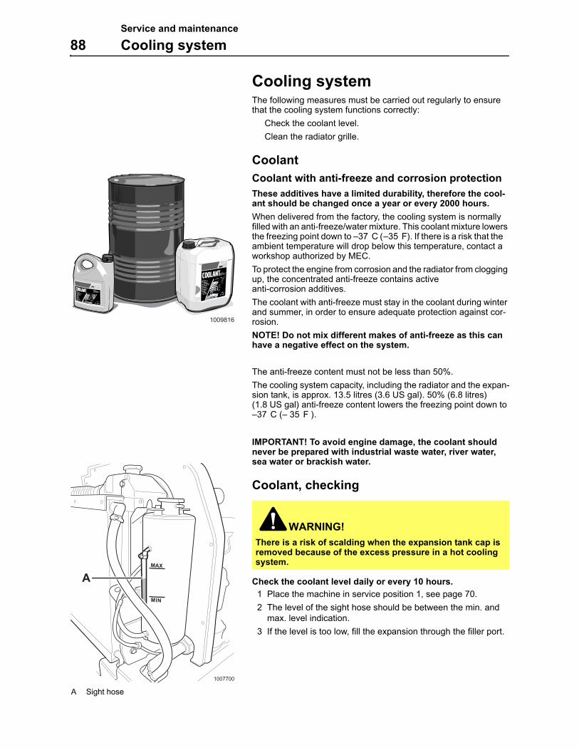
Service and maintenance
88 Cooling system
Cooling systemThe following measures must be carried out regularly to ensure that the cooling system functions correctly:
Check the coolant level.
Clean the radiator grille.
Coolant
Coolant with anti-freeze and corrosion protectionThese additives have a limited durability, therefore the cool-ant should be changed once a year or every 2000 hours.
When delivered from the factory, the cooling system is normally filled with an anti-freeze/water mixture. This coolant mixture lowers the freezing point down to –37 ° C (–35° F). If there is a risk that the ambient temperature will drop below this temperature, contact a workshop authorized by MEC.
To protect the engine from corrosion and the radiator from clogging up, the concentrated anti-freeze contains active anti-corrosion additives.
The coolant with anti-freeze must stay in the coolant during winter and summer, in order to ensure adequate protection against cor-rosion.
NOTE! Do not mix different makes of anti-freeze as this can have a negative effect on the system.
The anti-freeze content must not be less than 50%.
The cooling system capacity, including the radiator and the expan-sion tank, is approx. 13.5 litres (3.6 US gal). 50% (6.8 litres) (1.8 US gal) anti-freeze content lowers the freezing point down to –37 ° C (– 35 ° F ).
IMPORTANT! To avoid engine damage, the coolant should never be prepared with industrial waste water, river water, sea water or brackish water.
Coolant, checking
Check the coolant level daily or every 10 hours.
1 Place the machine in service position 1, see page 70.
2 The level of the sight hose should be between the min. and max. level indication.
3 If the level is too low, fill the expansion through the filler port.
WARNING!There is a risk of scalding when the expansion tank cap is removed because of the excess pressure in a hot cooling system.
1009816
1007700
AMAX
MIN
A Sight hose
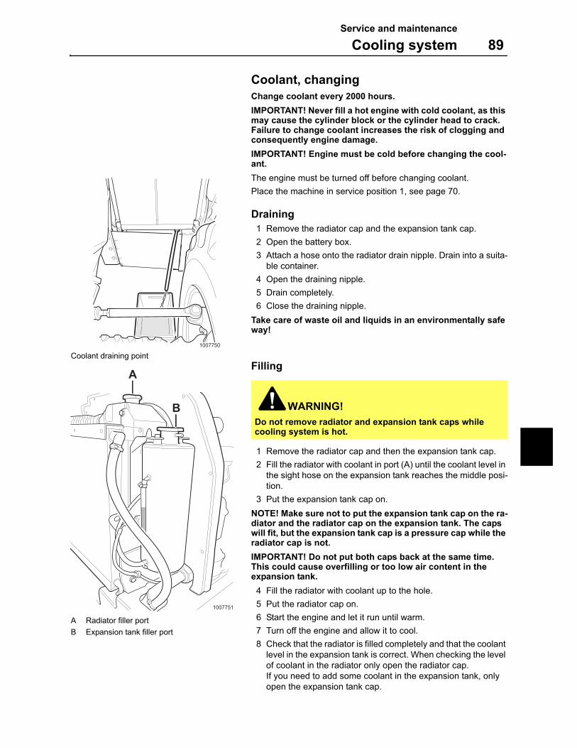
Service and maintenance
Cooling system 89
Coolant, changing
Change coolant every 2000 hours.
IMPORTANT! Never fill a hot engine with cold coolant, as this may cause the cylinder block or the cylinder head to crack. Failure to change coolant increases the risk of clogging and consequently engine damage.
IMPORTANT! Engine must be cold before changing the cool-ant.
The engine must be turned off before changing coolant.
Place the machine in service position 1, see page 70.
Draining
1 Remove the radiator cap and the expansion tank cap.
2 Open the battery box.
3 Attach a hose onto the radiator drain nipple. Drain into a suita-ble container.
4 Open the draining nipple.
5 Drain completely.
6 Close the draining nipple.
Take care of waste oil and liquids in an environmentally safe way!
Filling
1 Remove the radiator cap and then the expansion tank cap.
2 Fill the radiator with coolant in port (A) until the coolant level in the sight hose on the expansion tank reaches the middle posi-tion.
3 Put the expansion tank cap on.
NOTE! Make sure not to put the expansion tank cap on the ra-diator and the radiator cap on the expansion tank. The caps will fit, but the expansion tank cap is a pressure cap while the radiator cap is not.
IMPORTANT! Do not put both caps back at the same time. This could cause overfilling or too low air content in the expansion tank.
4 Fill the radiator with coolant up to the hole.
5 Put the radiator cap on.
6 Start the engine and let it run until warm.
7 Turn off the engine and allow it to cool.
8 Check that the radiator is filled completely and that the coolant level in the expansion tank is correct. When checking the level of coolant in the radiator only open the radiator cap.If you need to add some coolant in the expansion tank, only open the expansion tank cap.
WARNING!
Do not remove radiator and expansion tank caps while cooling system is hot.
1007750
Coolant draining point
1007751
A
B
A Radiator filler port
B Expansion tank filler port
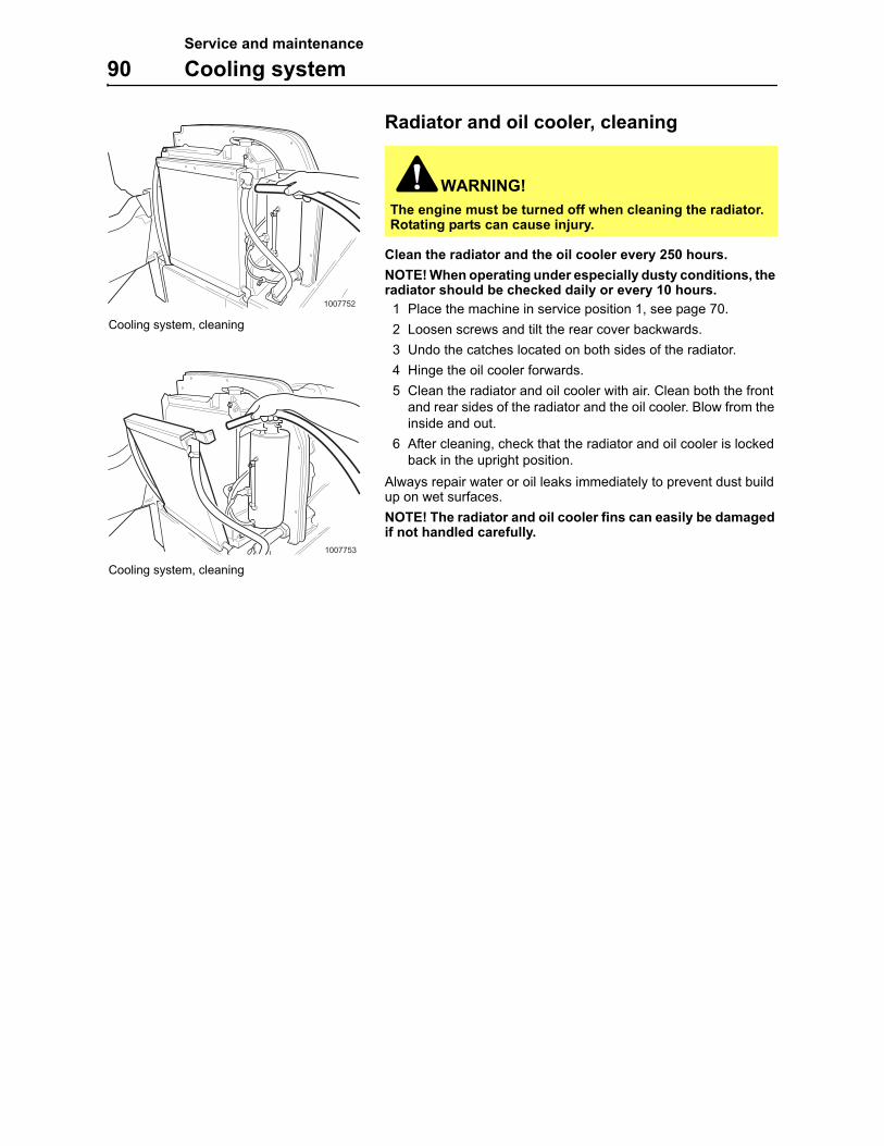
Service and maintenance
90 Cooling system
Radiator and oil cooler, cleaning
Clean the radiator and the oil cooler every 250 hours.
NOTE! When operating under especially dusty conditions, the radiator should be checked daily or every 10 hours.
1 Place the machine in service position 1, see page 70.
2 Loosen screws and tilt the rear cover backwards.
3 Undo the catches located on both sides of the radiator.
4 Hinge the oil cooler forwards.
5 Clean the radiator and oil cooler with air. Clean both the front and rear sides of the radiator and the oil cooler. Blow from the inside and out.
6 After cleaning, check that the radiator and oil cooler is locked back in the upright position.
Always repair water or oil leaks immediately to prevent dust build up on wet surfaces.
NOTE! The radiator and oil cooler fins can easily be damaged if not handled carefully.
WARNING!
The engine must be turned off when cleaning the radiator. Rotating parts can cause injury.
1007752
Cooling system, cleaning
1007753
Cooling system, cleaning
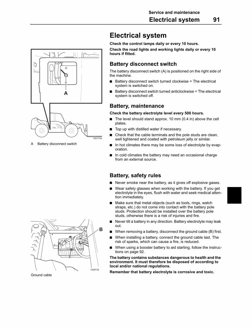
Service and maintenance
Electrical system 91
Electrical systemCheck the control lamps daily or every 10 hours.
Check the road lights and working lights daily or every 10 hours if fitted.
Battery disconnect switch
The battery disconnect switch (A) is positioned on the right side of the machine.
Battery disconnect switch turned clockwise = The electrical system is switched on.
Battery disconnect switch turned anticlockwise = The electrical system is switched off.
Battery, maintenance
Check the battery electrolyte level every 500 hours.
The level should stand approx. 10 mm (0.4 in) above the cell plates.
Top up with distilled water if necessary.
Check that the cable terminals and the pole studs are clean, well tightened and coated with petroleum jelly or similar.
In hot climates there may be some loss of electrolyte by evap-oration.
In cold climates the battery may need an occasional charge from an external source.
Battery, safety rules
Never smoke near the battery, as it gives off explosive gases.
Wear safety glasses when working with the battery. If you get electrolyte in the eyes, flush with water and seek medical atten-tion immediately.
Make sure that metal objects (such as tools, rings, watch straps, etc.) do not come into contact with the battery pole studs. Protection should be installed over the battery pole studs, otherwise there is a risk of injuries and fire.
Never tilt a battery in any direction. Battery electrolyte may leak out.
When removing a battery, disconnect the ground cable (B) first.
When installing a battery, connect the ground cable last. The risk of sparks, which can cause a fire, is reduced.
When using a booster battery to aid starting, follow the instruc-tions on page 92.
The battery contains substances dangerous to health and the environment. It must therefore be disposed of according to local and/or national regulations.
Remember that battery electrolyte is corrosive and toxic.
1007705
A
A Battery disconnect switch
1009732
B
Ground cable
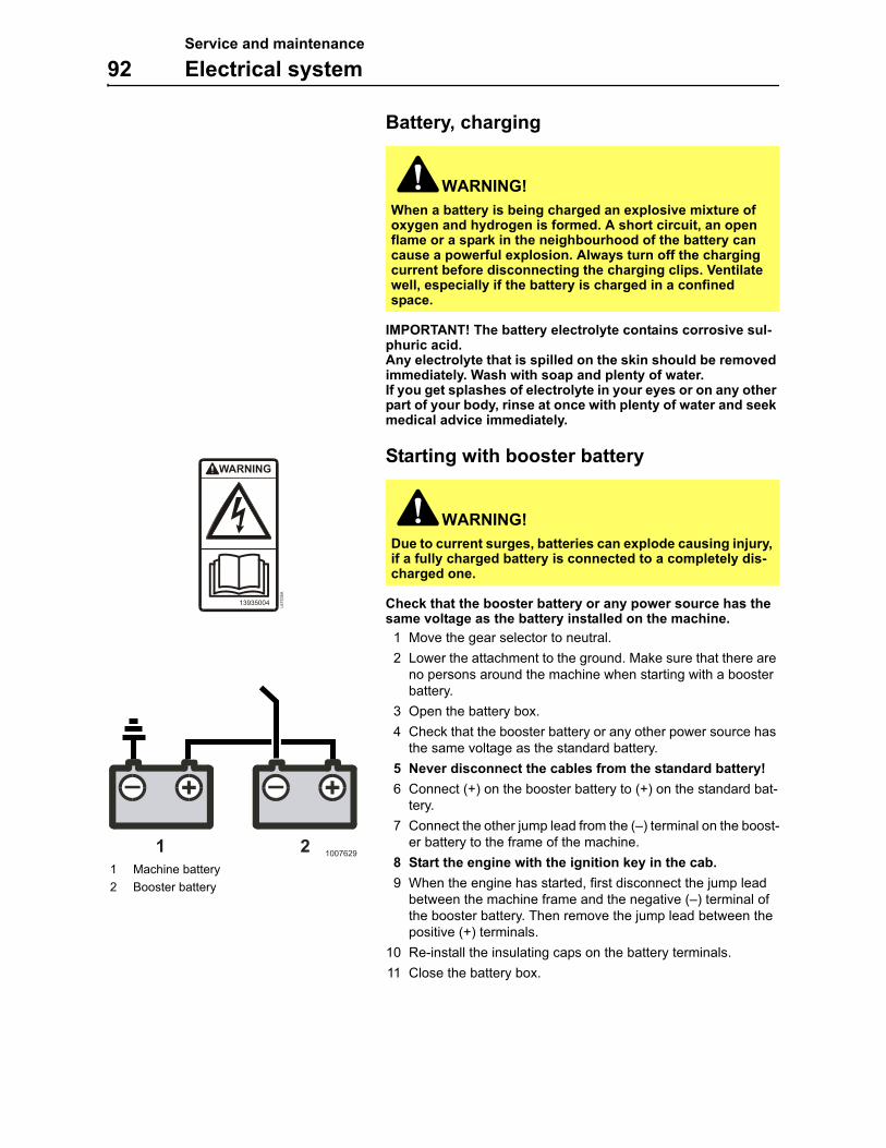
Service and maintenance
92 Electrical system
Battery, charging
IMPORTANT! The battery electrolyte contains corrosive sul-phuric acid.Any electrolyte that is spilled on the skin should be removed immediately. Wash with soap and plenty of water. If you get splashes of electrolyte in your eyes or on any other part of your body, rinse at once with plenty of water and seek medical advice immediately.
Starting with booster battery
Check that the booster battery or any power source has the same voltage as the battery installed on the machine.
1 Move the gear selector to neutral.
2 Lower the attachment to the ground. Make sure that there are no persons around the machine when starting with a booster battery.
3 Open the battery box.
4 Check that the booster battery or any other power source has the same voltage as the standard battery.
5 Never disconnect the cables from the standard battery!
6 Connect (+) on the booster battery to (+) on the standard bat-tery.
7 Connect the other jump lead from the (–) terminal on the boost-er battery to the frame of the machine.
8 Start the engine with the ignition key in the cab.
9 When the engine has started, first disconnect the jump lead between the machine frame and the negative (–) terminal of the booster battery. Then remove the jump lead between the positive (+) terminals.
10 Re-install the insulating caps on the battery terminals.
11 Close the battery box.
WARNING!
When a battery is being charged an explosive mixture of oxygen and hydrogen is formed. A short circuit, an open flame or a spark in the neighbourhood of the battery can cause a powerful explosion. Always turn off the charging current before disconnecting the charging clips. Ventilate well, especially if the battery is charged in a confined space.
WARNING!
Due to current surges, batteries can explode causing injury, if a fully charged battery is connected to a completely dis-charged one.
13935004
L6
75
35
A
1 21007629
1 Machine battery
2 Booster battery
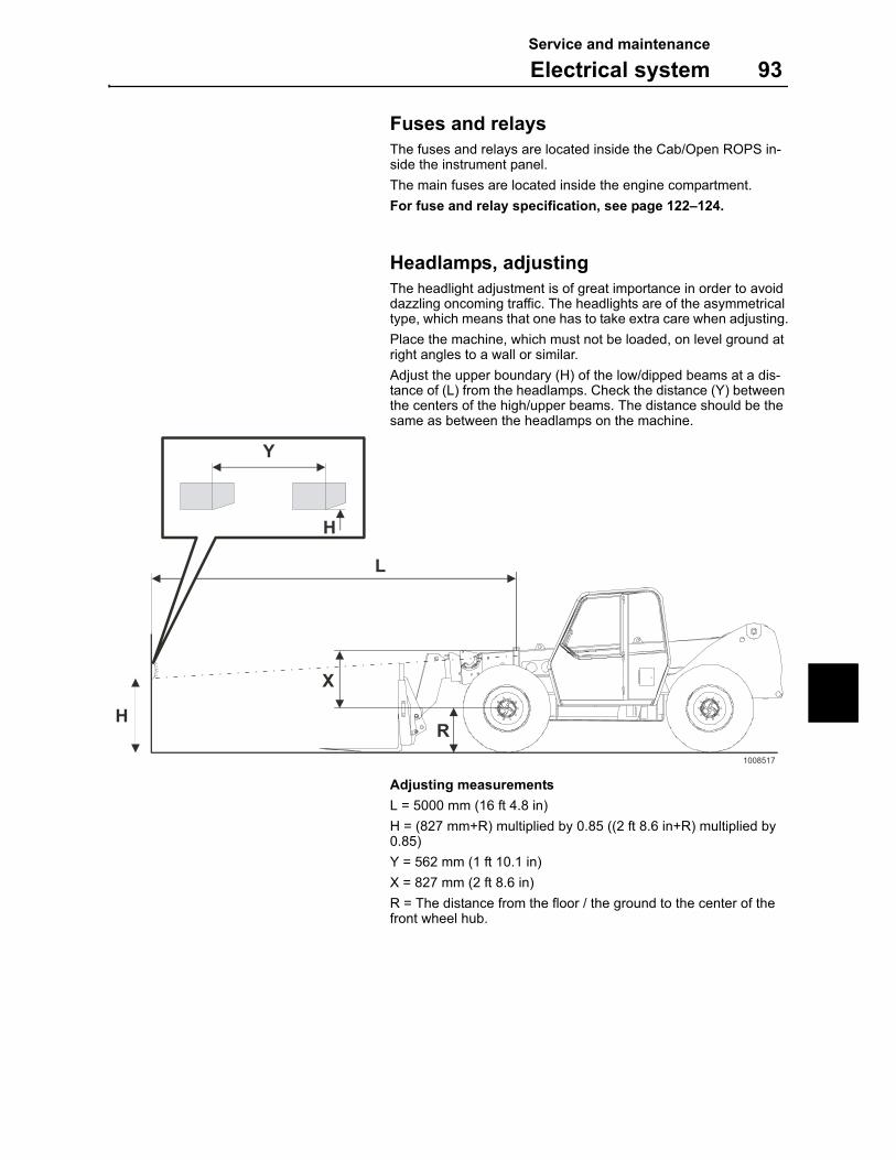
Service and maintenance
Electrical system 93
Fuses and relays
The fuses and relays are located inside the Cab/Open ROPS in-side the instrument panel.
The main fuses are located inside the engine compartment.
For fuse and relay specification, see page 122–124.
Headlamps, adjusting
The headlight adjustment is of great importance in order to avoid dazzling oncoming traffic. The headlights are of the asymmetrical type, which means that one has to take extra care when adjusting.
Place the machine, which must not be loaded, on level ground at right angles to a wall or similar.
Adjust the upper boundary (H) of the low/dipped beams at a dis-tance of (L) from the headlamps. Check the distance (Y) between the centers of the high/upper beams. The distance should be the same as between the headlamps on the machine.
Adjusting measurements
L = 5000 mm (16 ft 4.8 in)
H = (827 mm+R) multiplied by 0.85 ((2 ft 8.6 in+R) multiplied by 0.85)
Y = 562 mm (1 ft 10.1 in)
X = 827 mm (2 ft 8.6 in)
R = The distance from the floor / the ground to the center of the front wheel hub.
L
H
X
R1008517
Y
H
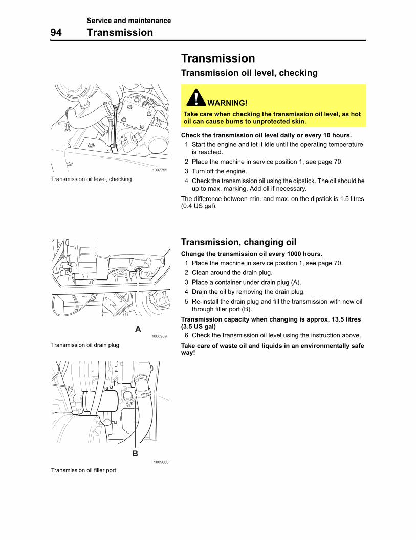
Service and maintenance
94 Transmission
TransmissionTransmission oil level, checking
Check the transmission oil level daily or every 10 hours.
1 Start the engine and let it idle until the operating temperature is reached.
2 Place the machine in service position 1, see page 70.
3 Turn off the engine.
4 Check the transmission oil using the dipstick. The oil should be up to max. marking. Add oil if necessary.
The difference between min. and max. on the dipstick is 1.5 litres (0.4 US gal).
Transmission, changing oil
Change the transmission oil every 1000 hours.
1 Place the machine in service position 1, see page 70.
2 Clean around the drain plug.
3 Place a container under drain plug (A).
4 Drain the oil by removing the drain plug.
5 Re-install the drain plug and fill the transmission with new oil through filler port (B).
Transmission capacity when changing is approx. 13.5 litres (3.5 US gal)
6 Check the transmission oil level using the instruction above.
Take care of waste oil and liquids in an environmentally safe way!
WARNING!
Take care when checking the transmission oil level, as hot oil can cause burns to unprotected skin.
1007755
Transmission oil level, checking
1008989
A
Transmission oil drain plug
1009060
B
Transmission oil filler port
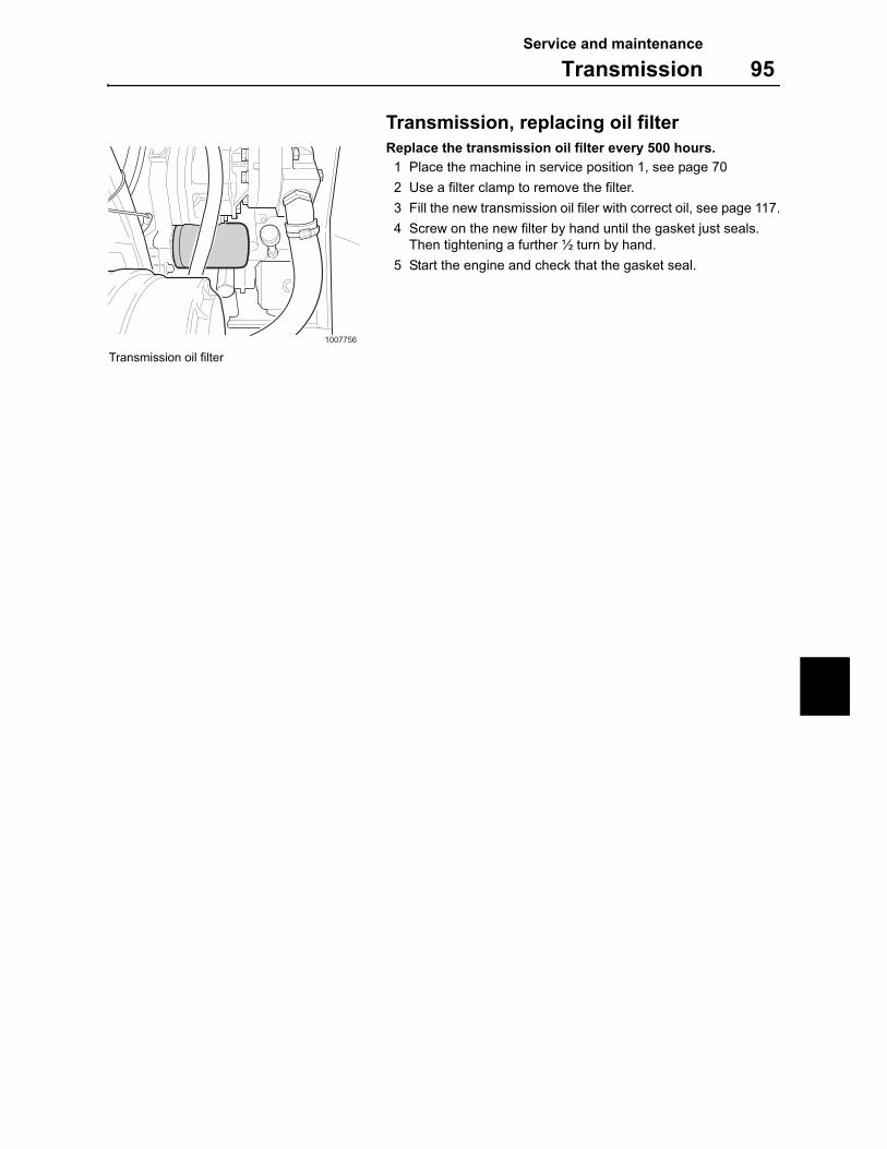
Service and maintenance
Transmission 95
Transmission, replacing oil filter
Replace the transmission oil filter every 500 hours.
1 Place the machine in service position 1, see page 70
2 Use a filter clamp to remove the filter.
3 Fill the new transmission oil filer with correct oil, see page 117.
4 Screw on the new filter by hand until the gasket just seals. Then tightening a further ½ turn by hand.
5 Start the engine and check that the gasket seal.
1007756
Transmission oil filter
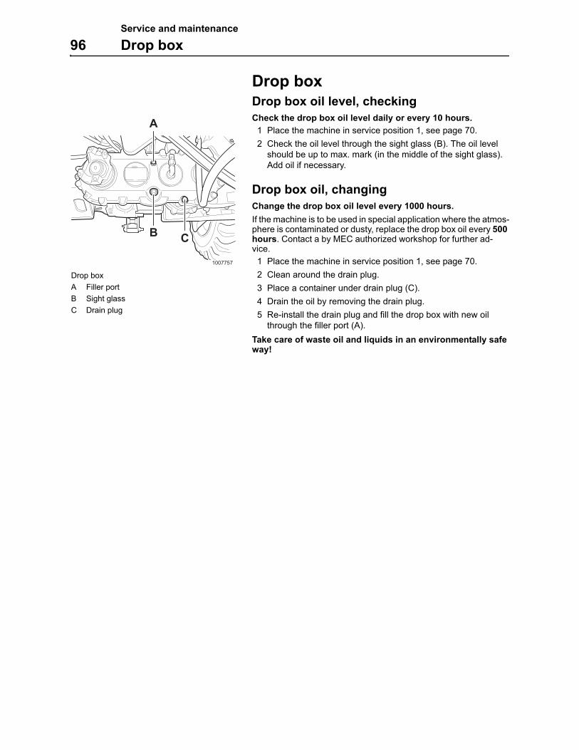
Service and maintenance
96 Drop box
Drop boxDrop box oil level, checking
Check the drop box oil level daily or every 10 hours.
1 Place the machine in service position 1, see page 70.
2 Check the oil level through the sight glass (B). The oil level should be up to max. mark (in the middle of the sight glass). Add oil if necessary.
Drop box oil, changing
Change the drop box oil level every 1000 hours.
If the machine is to be used in special application where the atmos-phere is contaminated or dusty, replace the drop box oil every 500hours. Contact a by MEC authorized workshop for further ad-vice.
1 Place the machine in service position 1, see page 70.
2 Clean around the drain plug.
3 Place a container under drain plug (C).
4 Drain the oil by removing the drain plug.
5 Re-install the drain plug and fill the drop box with new oil through the filler port (A).
Take care of waste oil and liquids in an environmentally safe way!
1007757
A
B C
Drop box
A Filler port
B Sight glass
C Drain plug
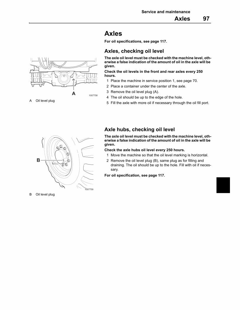
Service and maintenance
Axles 97
AxlesFor oil specifications, see page 117.
Axles, checking oil level
The axle oil level must be checked with the machine level, oth-erwise a false indication of the amount of oil in the axle will be given.
Check the oil levels in the front and rear axles every 250 hours.
1 Place the machine in service position 1, see page 70.
2 Place a container under the center of the axle.
3 Remove the oil level plug (A).
4 The oil should be up to the edge of the hole.
5 Fill the axle with more oil if necessary through the oil fill port.
Axle hubs, checking oil level
The axle oil level must be checked with the machine level, oth-erwise a false indication of the amount of oil in the axle will be given.
Check the axle hubs oil level every 250 hours.
1 Move the machine so that the oil level marking is horizontal.
2 Remove the oil level plug (B), same plug as for filling and draining. The oil should be up to the hole. Fill with oil if neces-sary.
For oil specification, see page 117.
1007758A
A Oil level plug
1007759
B
B Oil level plug
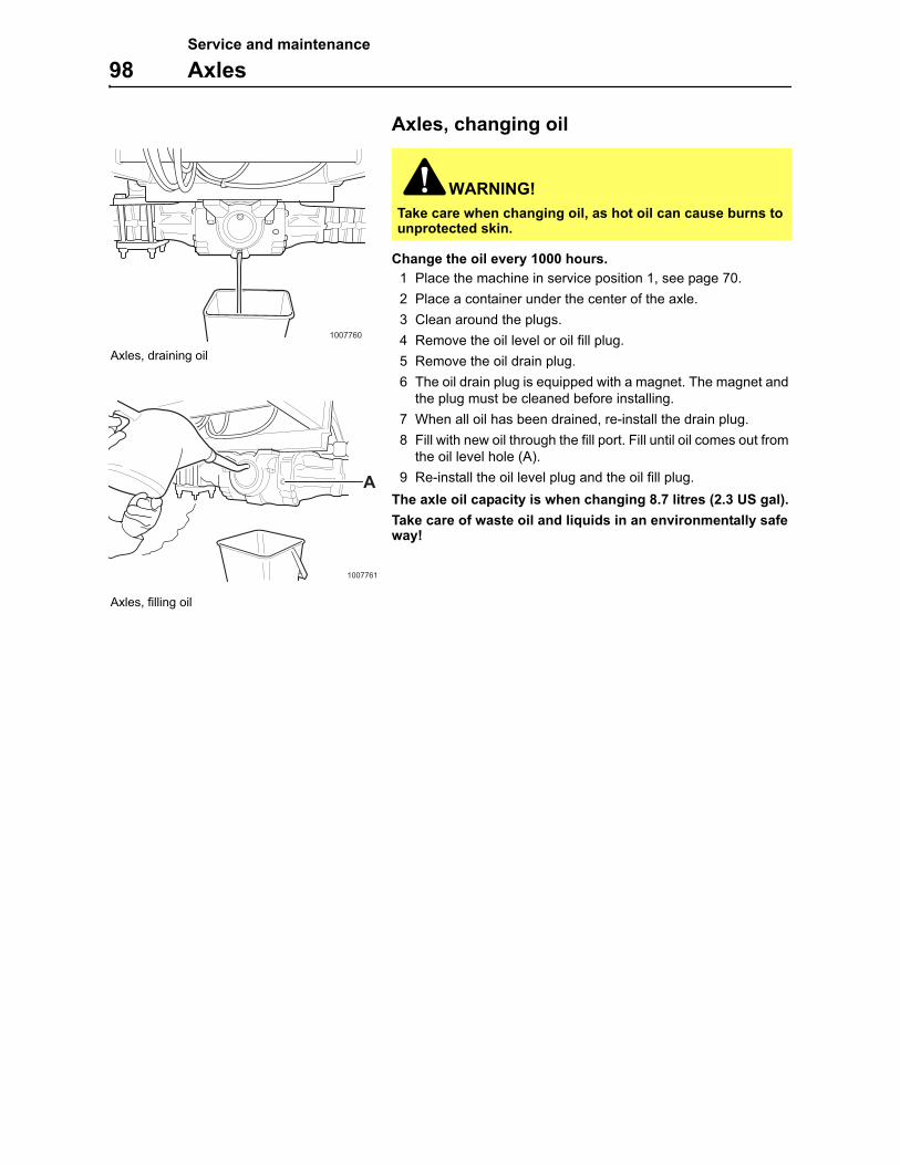
Service and maintenance
98 Axles
Axles, changing oil
Change the oil every 1000 hours.
1 Place the machine in service position 1, see page 70.
2 Place a container under the center of the axle.
3 Clean around the plugs.
4 Remove the oil level or oil fill plug.
5 Remove the oil drain plug.
6 The oil drain plug is equipped with a magnet. The magnet and the plug must be cleaned before installing.
7 When all oil has been drained, re-install the drain plug.
8 Fill with new oil through the fill port. Fill until oil comes out from the oil level hole (A).
9 Re-install the oil level plug and the oil fill plug.
The axle oil capacity is when changing 8.7 litres (2.3 US gal).
Take care of waste oil and liquids in an environmentally safe way!
WARNING!
Take care when changing oil, as hot oil can cause burns to unprotected skin.
1007760
Axles, draining oil
1007761
A
Axles, filling oil
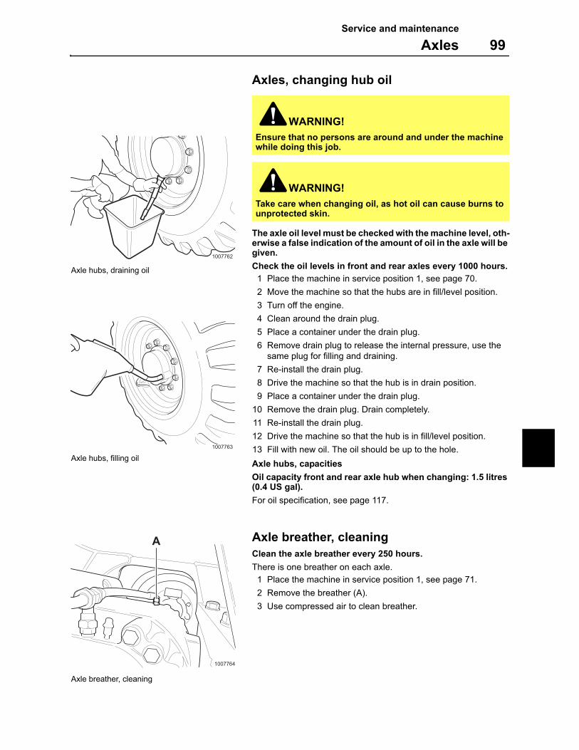
Service and maintenance
Axles 99
Axles, changing hub oil
The axle oil level must be checked with the machine level, oth-erwise a false indication of the amount of oil in the axle will be given.
Check the oil levels in front and rear axles every 1000 hours.
1 Place the machine in service position 1, see page 70.
2 Move the machine so that the hubs are in fill/level position.
3 Turn off the engine.
4 Clean around the drain plug.
5 Place a container under the drain plug.
6 Remove drain plug to release the internal pressure, use the same plug for filling and draining.
7 Re-install the drain plug.
8 Drive the machine so that the hub is in drain position.
9 Place a container under the drain plug.
10 Remove the drain plug. Drain completely.
11 Re-install the drain plug.
12 Drive the machine so that the hub is in fill/level position.
13 Fill with new oil. The oil should be up to the hole.
Axle hubs, capacities
Oil capacity front and rear axle hub when changing: 1.5 litres (0.4 US gal).
For oil specification, see page 117.
Axle breather, cleaning
Clean the axle breather every 250 hours.
There is one breather on each axle.
1 Place the machine in service position 1, see page 71.
2 Remove the breather (A).
3 Use compressed air to clean breather.
WARNING!
Ensure that no persons are around and under the machine while doing this job.
WARNING!
Take care when changing oil, as hot oil can cause burns to unprotected skin.
1007762
Axle hubs, draining oil
1007763
Axle hubs, filling oil
1007764
A
Axle breather, cleaning

Service and maintenance
100 Brake system
Brake systemService jobs on the brake system should only be carried out by a MEC authorized workshop.
For checking service brakes and parking brakes functionality, see page 49.
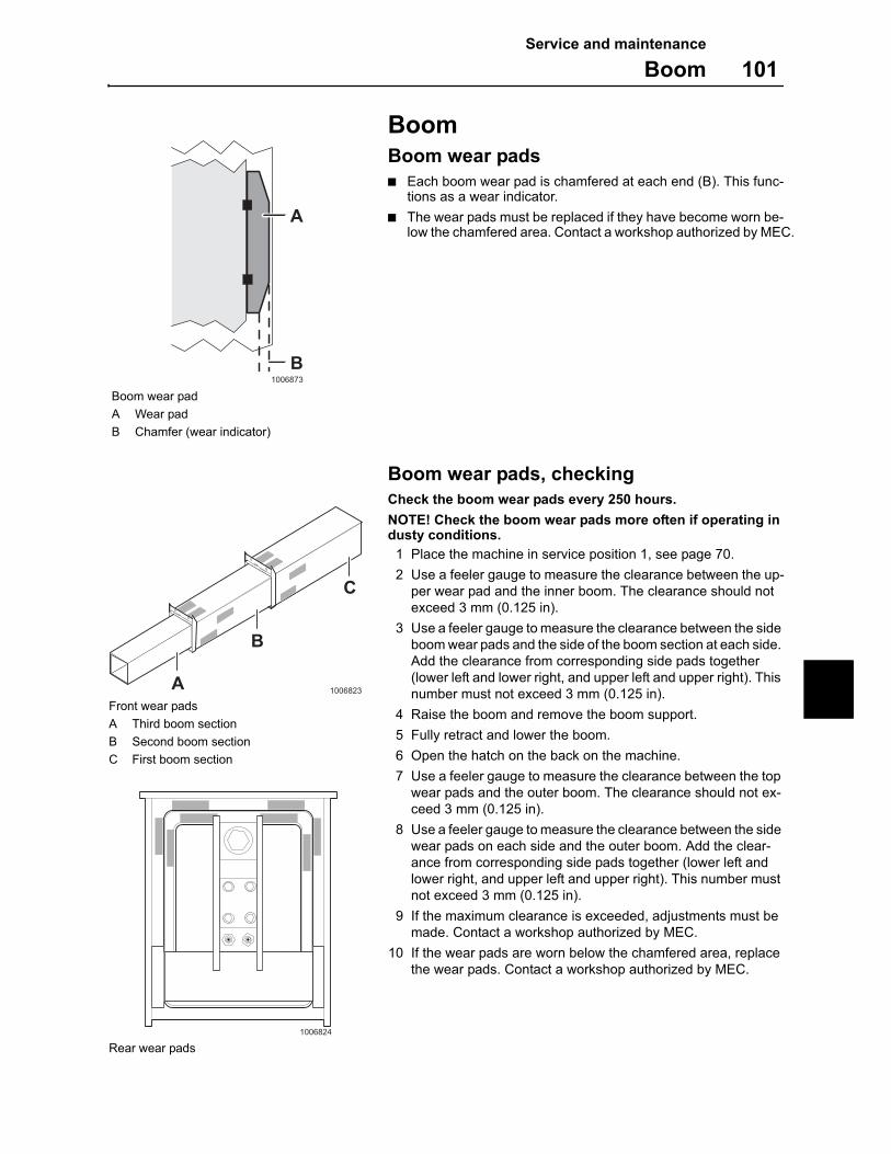
Service and maintenance
Boom 101
BoomBoom wear pads
Each boom wear pad is chamfered at each end (B). This func-tions as a wear indicator.
The wear pads must be replaced if they have become worn be-low the chamfered area. Contact a workshop authorized by MEC.
Boom wear pads, checking
Check the boom wear pads every 250 hours.
NOTE! Check the boom wear pads more often if operating in dusty conditions.
1 Place the machine in service position 1, see page 70.
2 Use a feeler gauge to measure the clearance between the up-per wear pad and the inner boom. The clearance should not exceed 3 mm (0.125 in).
3 Use a feeler gauge to measure the clearance between the side boom wear pads and the side of the boom section at each side. Add the clearance from corresponding side pads together (lower left and lower right, and upper left and upper right). This number must not exceed 3 mm (0.125 in).
4 Raise the boom and remove the boom support.
5 Fully retract and lower the boom.
6 Open the hatch on the back on the machine.
7 Use a feeler gauge to measure the clearance between the top wear pads and the outer boom. The clearance should not ex-ceed 3 mm (0.125 in).
8 Use a feeler gauge to measure the clearance between the side wear pads on each side and the outer boom. Add the clear-ance from corresponding side pads together (lower left and lower right, and upper left and upper right). This number must not exceed 3 mm (0.125 in).
9 If the maximum clearance is exceeded, adjustments must be made. Contact a workshop authorized by MEC.
10 If the wear pads are worn below the chamfered area, replace the wear pads. Contact a workshop authorized by MEC.
A
B1006873
Boom wear pad
A Wear pad
B Chamfer (wear indicator)
A
B
C
1006823
Front wear pads
A Third boom section
B Second boom section
C First boom section
1006824
Rear wear pads
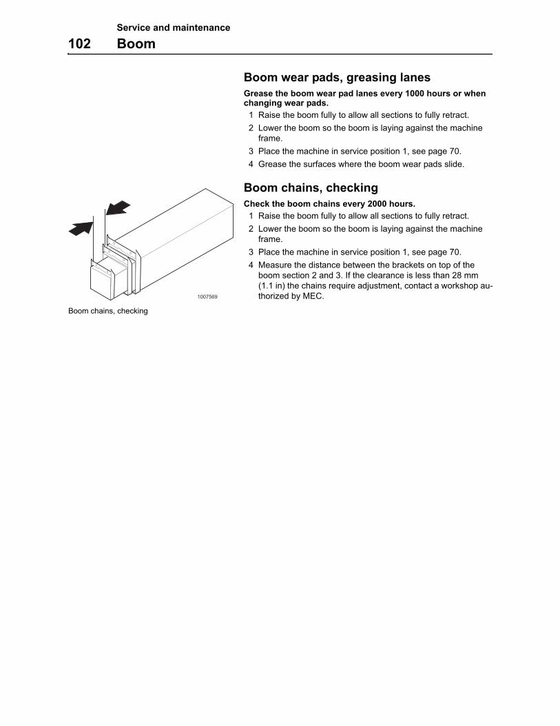
Service and maintenance
102 Boom
Boom wear pads, greasing lanes
Grease the boom wear pad lanes every 1000 hours or when changing wear pads.
1 Raise the boom fully to allow all sections to fully retract.
2 Lower the boom so the boom is laying against the machine frame.
3 Place the machine in service position 1, see page 70.
4 Grease the surfaces where the boom wear pads slide.
Boom chains, checking
Check the boom chains every 2000 hours.
1 Raise the boom fully to allow all sections to fully retract.
2 Lower the boom so the boom is laying against the machine frame.
3 Place the machine in service position 1, see page 70.
4 Measure the distance between the brackets on top of the boom section 2 and 3. If the clearance is less than 28 mm (1.1 in) the chains require adjustment, contact a workshop au-thorized by MEC.1007569
Boom chains, checking
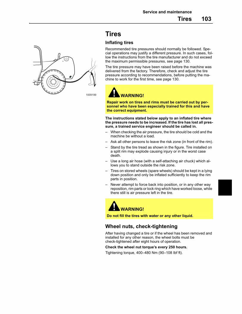
Service and maintenance
Tires 103
TiresInflating tires
Recommended tire pressures should normally be followed. Spe-cial operations may justify a different pressure. In such cases, fol-low the instructions from the tire manufacturer and do not exceed the maximum permissible pressures, see page 130.
The tire pressure may have been raised before the machine was delivered from the factory. Therefore, check and adjust the tire pressure according to recommendations, before putting the ma-chine to work for the first time, see page 130.
The instructions stated below apply to an inflated tire where the pressure needs to be increased. If the tire has lost all pres-sure, a trained service engineer should be called in.
– When checking the air pressure, the tire should be cold and the machine be without a load.
– Ask all other persons to leave the risk zone (in front of the rim).
– Stand by the tire tread as shown in the figure. Tire installed on a split rim may explode causing injury or in the worst case death.
– Use a long air hose (with a self-attaching air chuck) which al-lows you to stand outside the risk zone.
– Tires on stored wheels (spare wheels) should be kept in a lying down position and only be inflated sufficiently to keep the rim parts in position.
– Never attempt to force back into position, or in any other way reposition, rim parts or lock ring which have worked loose, while there still is air pressure left in the tire.
Wheel nuts, check-tightening
After having changed a tire or if the wheel has been removed and installed for any other reason, the wheel bolts must be check-tightened after eight hours of operation.
Check the wheel nut torque’s every 250 hours.
Tightening torque, 400–480 Nm (90–108 Ibf ft).
WARNING!
Repair work on tires and rims must be carried out by per-sonnel who have been especially trained for this and have the correct equipment.
WARNING!
Do not fill the tires with water or any other liquid.
1009199
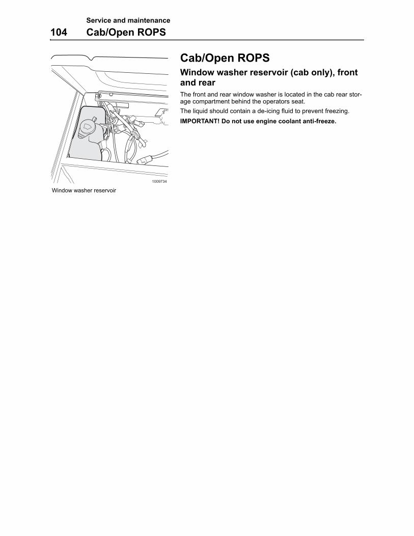
Service and maintenance
104 Cab/Open ROPS
Cab/Open ROPSWindow washer reservoir (cab only), front and rear
The front and rear window washer is located in the cab rear stor-age compartment behind the operators seat.
The liquid should contain a de-icing fluid to prevent freezing.
IMPORTANT! Do not use engine coolant anti-freeze.
1009734
Window washer reservoir
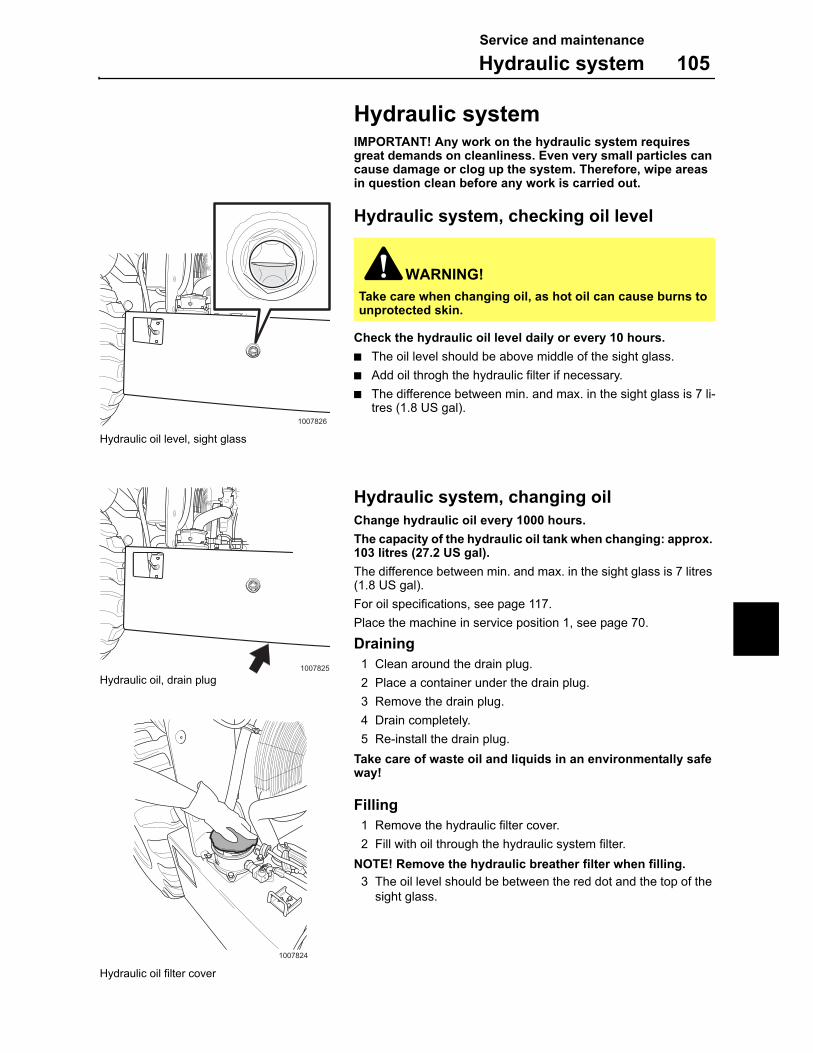
Service and maintenance
Hydraulic system 105
Hydraulic systemIMPORTANT! Any work on the hydraulic system requires great demands on cleanliness. Even very small particles can cause damage or clog up the system. Therefore, wipe areas in question clean before any work is carried out.
Hydraulic system, checking oil level
Check the hydraulic oil level daily or every 10 hours.
The oil level should be above middle of the sight glass.
Add oil throgh the hydraulic filter if necessary.
The difference between min. and max. in the sight glass is 7 li-tres (1.8 US gal).
Hydraulic system, changing oil
Change hydraulic oil every 1000 hours.
The capacity of the hydraulic oil tank when changing: approx. 103 litres (27.2 US gal).
The difference between min. and max. in the sight glass is 7 litres (1.8 US gal).
For oil specifications, see page 117.
Place the machine in service position 1, see page 70.
Draining
1 Clean around the drain plug.
2 Place a container under the drain plug.
3 Remove the drain plug.
4 Drain completely.
5 Re-install the drain plug.
Take care of waste oil and liquids in an environmentally safe way!
Filling
1 Remove the hydraulic filter cover.
2 Fill with oil through the hydraulic system filter.
NOTE! Remove the hydraulic breather filter when filling.
3 The oil level should be between the red dot and the top of the sight glass.
WARNING!
Take care when changing oil, as hot oil can cause burns to unprotected skin.
1007826
Hydraulic oil level, sight glass
1007825
Hydraulic oil, drain plug
Hydraulic oil filter cover
1007824
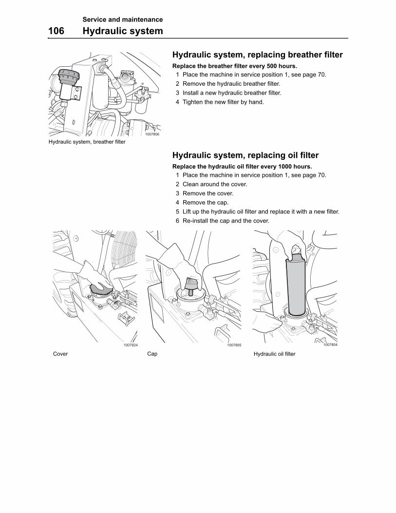
Service and maintenance
106 Hydraulic system
Hydraulic system, replacing breather filter
Replace the breather filter every 500 hours.
1 Place the machine in service position 1, see page 70.
2 Remove the hydraulic breather filter.
3 Install a new hydraulic breather filter.
4 Tighten the new filter by hand.
Hydraulic system, replacing oil filter
Replace the hydraulic oil filter every 1000 hours.
1 Place the machine in service position 1, see page 70.
2 Clean around the cover.
3 Remove the cover.
4 Remove the cap.
5 Lift up the hydraulic oil filter and replace it with a new filter.
6 Re-install the cap and the cover.
1007806
Hydraulic system, breather filter
10078041007824
Hydraulic oil filter
1007805
CapCover
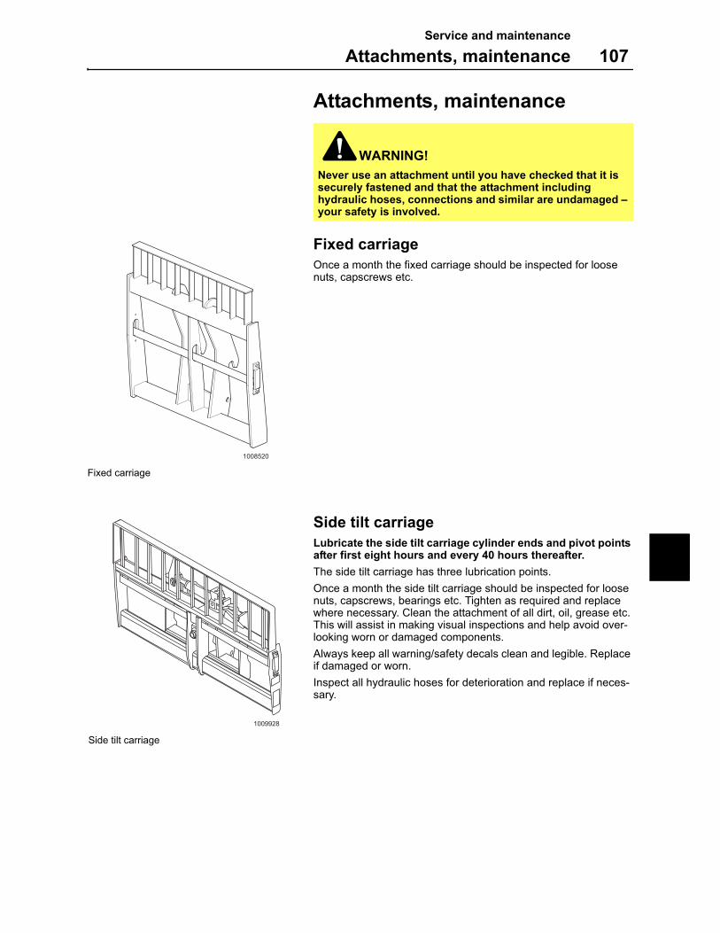
Service and maintenance
Attachments, maintenance 107
Attachments, maintenance
Fixed carriage
Once a month the fixed carriage should be inspected for loose nuts, capscrews etc.
Side tilt carriage
Lubricate the side tilt carriage cylinder ends and pivot points after first eight hours and every 40 hours thereafter.
The side tilt carriage has three lubrication points.
Once a month the side tilt carriage should be inspected for loose nuts, capscrews, bearings etc. Tighten as required and replace where necessary. Clean the attachment of all dirt, oil, grease etc. This will assist in making visual inspections and help avoid over-looking worn or damaged components.
Always keep all warning/safety decals clean and legible. Replace if damaged or worn.
Inspect all hydraulic hoses for deterioration and replace if neces-sary.
WARNING!
Never use an attachment until you have checked that it is securely fastened and that the attachment including hydraulic hoses, connections and similar are undamaged – your safety is involved.
1008520
Fixed carriage
1009928
Side tilt carriage

Service and maintenance
108 Attachments, maintenance
Side shift carriage
Once a month the fixed carriage should be inspected for loose nuts, capscrews etc.
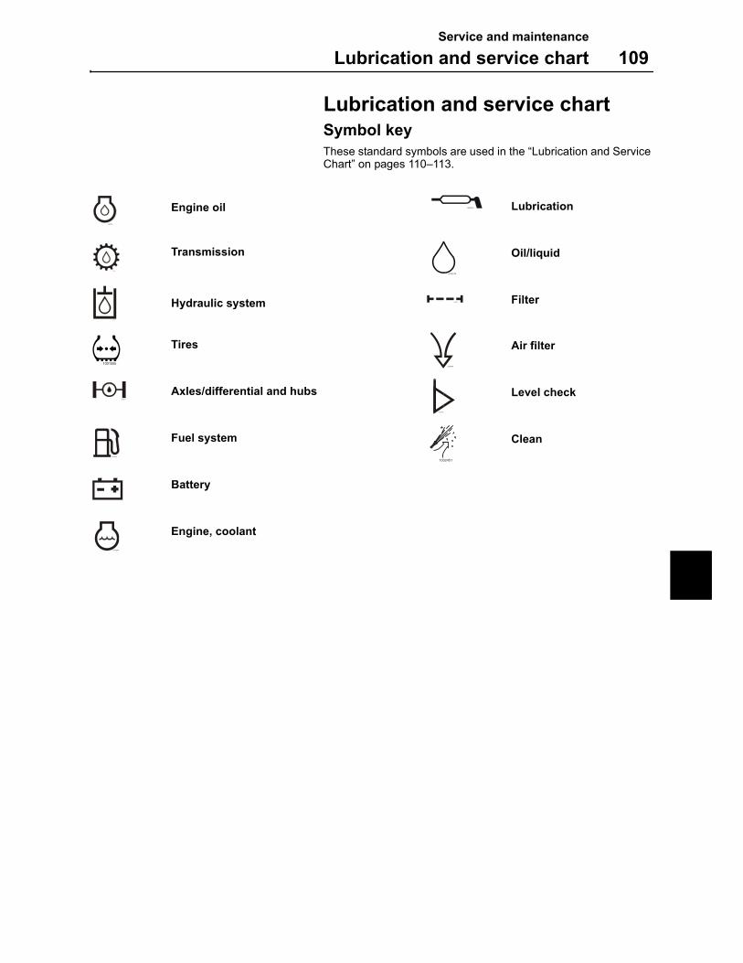
Service and maintenance
Lubrication and service chart 109
Lubrication and service chartSymbol key
These standard symbols are used in the “Lubrication and Service Chart” on pages 110–113.
Engine oil Lubrication
Transmission Oil/liquid
Hydraulic system Filter
Tires Air filter
Axles/differential and hubs Level check
Fuel system Clean
Battery
Engine, coolant
L66544A
L66542A
L66627A
L66543A
L66625A
1001505L66626A
L66636A
L66546A
1002451
L66633A
L66629A
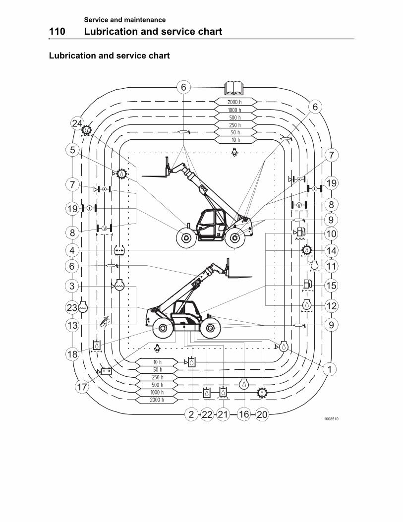
Service and maintenance
110 Lubrication and service chart
Lubrication and service chart
10 h
2000 h
500 h1000 h
250 h 50 h
2000 h
250 h 50 h10 h
1000 h500 h
1
6
7
19
8
9
10
14
11
15
12
2122
17
18
13
23
3
4
6
8
19
7
5
24
2016
6
2
9
1008510
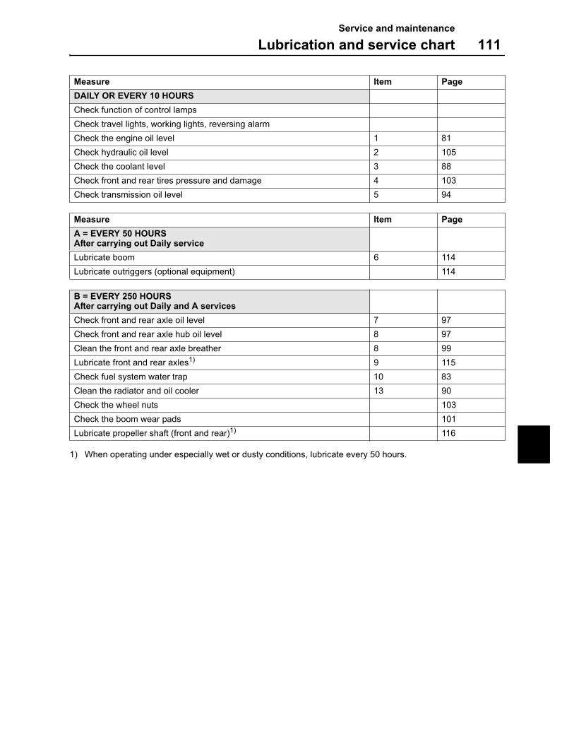
Service and maintenance
Lubrication and service chart 111
1) When operating under especially wet or dusty conditions, lubricate every 50 hours.
Measure Item Page
DAILY OR EVERY 10 HOURS
Check function of control lamps
Check travel lights, working lights, reversing alarm
Check the engine oil level 1 81
Check hydraulic oil level 2 105
Check the coolant level 3 88
Check front and rear tires pressure and damage 4 103
Check transmission oil level 5 94
Measure Item Page
A = EVERY 50 HOURSAfter carrying out Daily service
Lubricate boom 6 114
Lubricate outriggers (optional equipment) 114
B = EVERY 250 HOURSAfter carrying out Daily and A services
Check front and rear axle oil level 7 97
Check front and rear axle hub oil level 8 97
Clean the front and rear axle breather 8 99
Lubricate front and rear axles1) 9 115
Check fuel system water trap 10 83
Clean the radiator and oil cooler 13 90
Check the wheel nuts 103
Check the boom wear pads 101
Lubricate propeller shaft (front and rear)1) 116
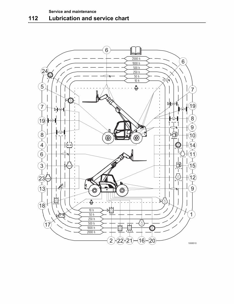
Service and maintenance
112 Lubrication and service chart
10 h
2000 h
500 h1000 h
250 h 50 h
2000 h
250 h 50 h10 h
1000 h500 h
1
6
7
19
8
9
10
14
11
15
12
2122
17
18
13
23
3
4
6
8
19
7
5
24
2016
6
2
9
1008510
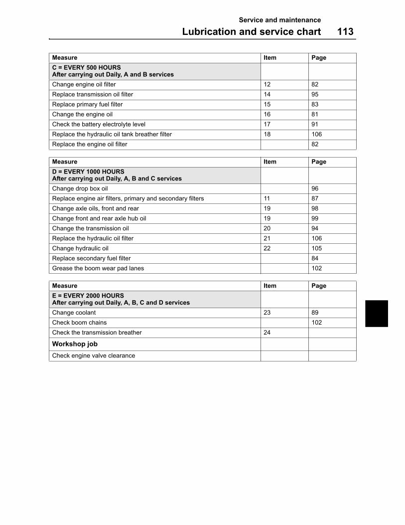
Service and maintenance
Lubrication and service chart 113
Measure Item Page
C = EVERY 500 HOURSAfter carrying out Daily, A and B services
Change engine oil filter 12 82
Replace transmission oil filter 14 95
Replace primary fuel filter 15 83
Change the engine oil 16 81
Check the battery electrolyte level 17 91
Replace the hydraulic oil tank breather filter 18 106
Replace the engine oil filter 82
Measure Item Page
D = EVERY 1000 HOURSAfter carrying out Daily, A, B and C services
Change drop box oil 96
Replace engine air filters, primary and secondary filters 11 87
Change axle oils, front and rear 19 98
Change front and rear axle hub oil 19 99
Change the transmission oil 20 94
Replace the hydraulic oil filter 21 106
Change hydraulic oil 22 105
Replace secondary fuel filter 84
Grease the boom wear pad lanes 102
Measure Item Page
E = EVERY 2000 HOURSAfter carrying out Daily, A, B, C and D services
Change coolant 23 89
Check boom chains 102
Check the transmission breather 24
Workshop job
Check engine valve clearance
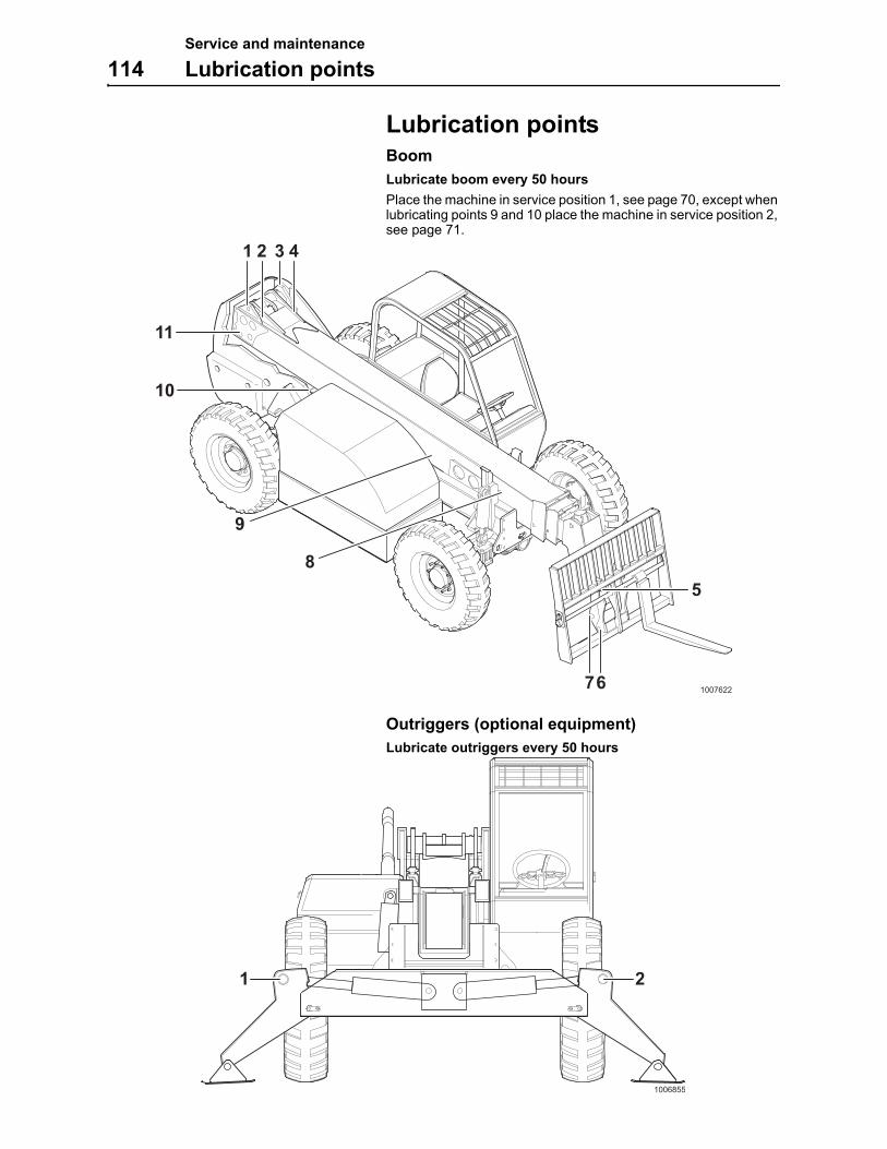
Service and maintenance
114 Lubrication points
Lubrication pointsBoom
Lubricate boom every 50 hours
Place the machine in service position 1, see page 70, except when lubricating points 9 and 10 place the machine in service position 2, see page 71.
Outriggers (optional equipment)
Lubricate outriggers every 50 hours
1 2 3 4
5
6
8
9
10
11
71007622
1 2
1006855
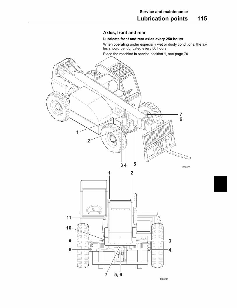
Service and maintenance
Lubrication points 115
Axles, front and rear
Lubricate front and rear axles every 250 hours
When operating under especially wet or dusty conditions, the ax-les should be lubricated every 50 hours.
Place the machine in service position 1, see page 70.
1
2
3 4 5
67
1007623
1 2
3
4
9
10
11
8
5, 671006849
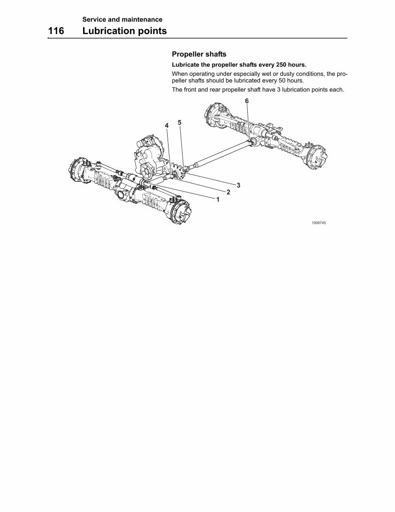
Service and maintenance
116 Lubrication points
Propeller shafts
Lubricate the propeller shafts every 250 hours.
When operating under especially wet or dusty conditions, the pro-peller shafts should be lubricated every 50 hours.
The front and rear propeller shaft have 3 lubrication points each.
12
3
4 5
6
1008745
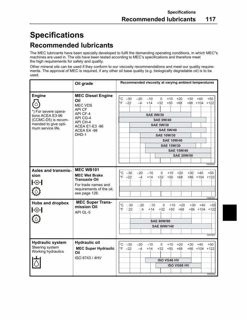
Specifications
Recommended lubricants 117
Specifications
Recommended lubricantsThe MEC lubricants have been specially developed to fulfil the demanding operating conditions, in which MEC"smachines are used in. The oils have been tested according to MEC’s specifications and therefore meet the high requirements for safety and quality.
Other mineral oils can be used if they conform to our viscosity recommendations and meet our quality require-ments. The approval of MEC is required, if any other oil base quality (e.g. biologically degradable oil) is to be used.
Oil grade Recommended viscosity at varying ambient temperatures
Engine
*) For severe opera-tions ACEA E3-96 (CCMC-D5) is recom-mended to give opti-mum service life.
MEC Diesel Engine OilMEC VDS API CFAPI CF-4API CG-4API CH-4ACEA E1-E3 -96 ACEA E4 -98DHD-1
Axles and transmis-sion
MEC WB101
MEC Wet Brake Transaxle Oil
For trade names and requirements of the oil, see page 126.
Hubs and dropbox MEC Super Trans-mission Oil
API GL-5
Hydraulic systemSteering systemWorking hydraulics
Hydraulic oil
MEC Super Hydraulic Oil
ISO 6743 / 4HV
°C –30 –20 –10 0 +10 +20 +30 +40 +50
°F –22 –4 +14 +32 +50 +68 +86 +104 +122
SAE 0W/30
SAE 0W/40
SAE 5W/30
SAE 5W/40
SAE 10W/30
SAE 10W/40
SAE 15W/30
SAE 15W/40
SAE 20W/50
1005840
L66542A
1006493
L66542A
°C �30 �20 �10 0 +10 +20 +30 +40 +50
°F �22 �4 +14 +32 +50 +68 +86 +104 +122
SAE 80W/140SAE 80W/90
1007807
L66543A
°C –30 –20 –10 0 +10 +20 +30 +40 +50
°F –22 –4 +14 +32 +50 +68 +86 +104 +122
ISO VG46 HV
ISO VG68 HV
1005842
Specifications
118 Recommended lubricants
Grease
General lubrication points
Grease with lithium base with EP additives and consistency NLGI No. 2.
Boom wear pad lanes
Grease with Keystone Zeniplex Aluminium Complex EP Grease.
Cooling system
–MEC original anti-freeze
– USA: Coolant norm ASTM D4985
Fuel
Quality requirements
The fuel should at least meet the legal requirements, and national and international standards for marketed fuels, for example: EN590 (with nationally adapted temperature requirements), ASTM D 975 No 1D and 2D, BS 2896 Class A 2, ISO 8217 DMX.
The cetane number must not be below 49 according to EN 590 ISO 5165 (40 according to ASTM D 975 Grade No 1-D and 2-D). If the cetane number is too low, it may cause starting problems and white smoke development.
Sulphur content
According to legal requirements (the sulphur content must not ex-ceed 0.3 percent by mass according to ISO 8754, EN 24260).
L66544A
L66545A
L66546A
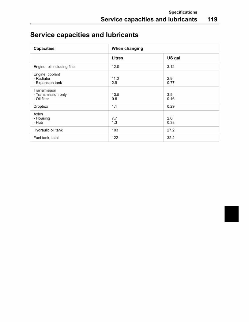
Specifications
Service capacities and lubricants 119
Service capacities and lubricants
Capacities When changing
Litres US gal
Engine, oil including filter 12.0 3.12
Engine, coolant- Radiator- Expansion tank
11.02.9
2.90.77
Transmission- Transmission only- Oil filter
13.50.6
3.50.16
Dropbox 1.1 0.29
Axles- Housing- Hub
7.71.3
2.00.38
Hydraulic oil tank 103 27.2
Fuel tank, total 122 32.2
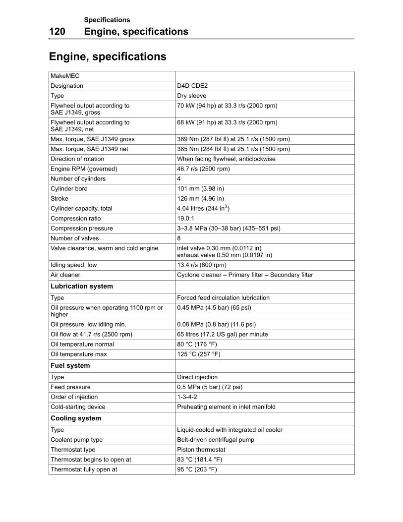
Specifications
120 Engine, specifications
Engine, specifications
MakeMEC
Designation D4D CDE2
Type Dry sleeve
Flywheel output according to SAE J1349, gross
70 kW (94 hp) at 33.3 r/s (2000 rpm)
Flywheel output according to SAE J1349, net
68 kW (91 hp) at 33.3 r/s (2000 rpm)
Max. torque, SAE J1349 gross 389 Nm (287 Ibf ft) at 25.1 r/s (1500 rpm)
Max. torque, SAE J1349 net 385 Nm (284 Ibf ft) at 25.1 r/s (1500 rpm)
Direction of rotation When facing flywheel, anticlockwise
Engine RPM (governed) 46.7 r/s (2500 rpm)
Number of cylinders 4
Cylinder bore 101 mm (3.98 in)
Stroke 126 mm (4.96 in)
Cylinder capacity, total 4.04 litres (244 in3)
Compression ratio 19.0:1
Compression pressure 3–3.8 MPa (30–38 bar) (435–551 psi)
Number of valves 8
Valve clearance, warm and cold engine inlet valve 0.30 mm (0.0112 in)exhaust valve 0.50 mm (0.0197 in)
Idling speed, low 13.4 r/s (800 rpm)
Air cleaner Cyclone cleaner – Primary filter – Secondary filter
Lubrication system
Type Forced feed circulation lubrication
Oil pressure when operating 1100 rpm or higher
0.45 MPa (4.5 bar) (65 psi)
Oil pressure, low idling min. 0.08 MPa (0.8 bar) (11.6 psi)
Oil flow at 41.7 r/s (2500 rpm) 65 litres (17.2 US gal) per minute
Oil temperature normal 80 °C (176 °F)
Oil temperature max 125 °C (257 °F)
Fuel system
Type Direct injection
Feed pressure 0.5 MPa (5 bar) (72 psi)
Order of injection 1-3-4-2
Cold-starting device Preheating element in inlet manifold
Cooling system
Type Liquid-cooled with integrated oil cooler
Coolant pump type Belt-driven centrifugal pump
Thermostat type Piston thermostat
Thermostat begins to open at 83 °C (181.4 °F)
Thermostat fully open at 95 °C (203 °F)
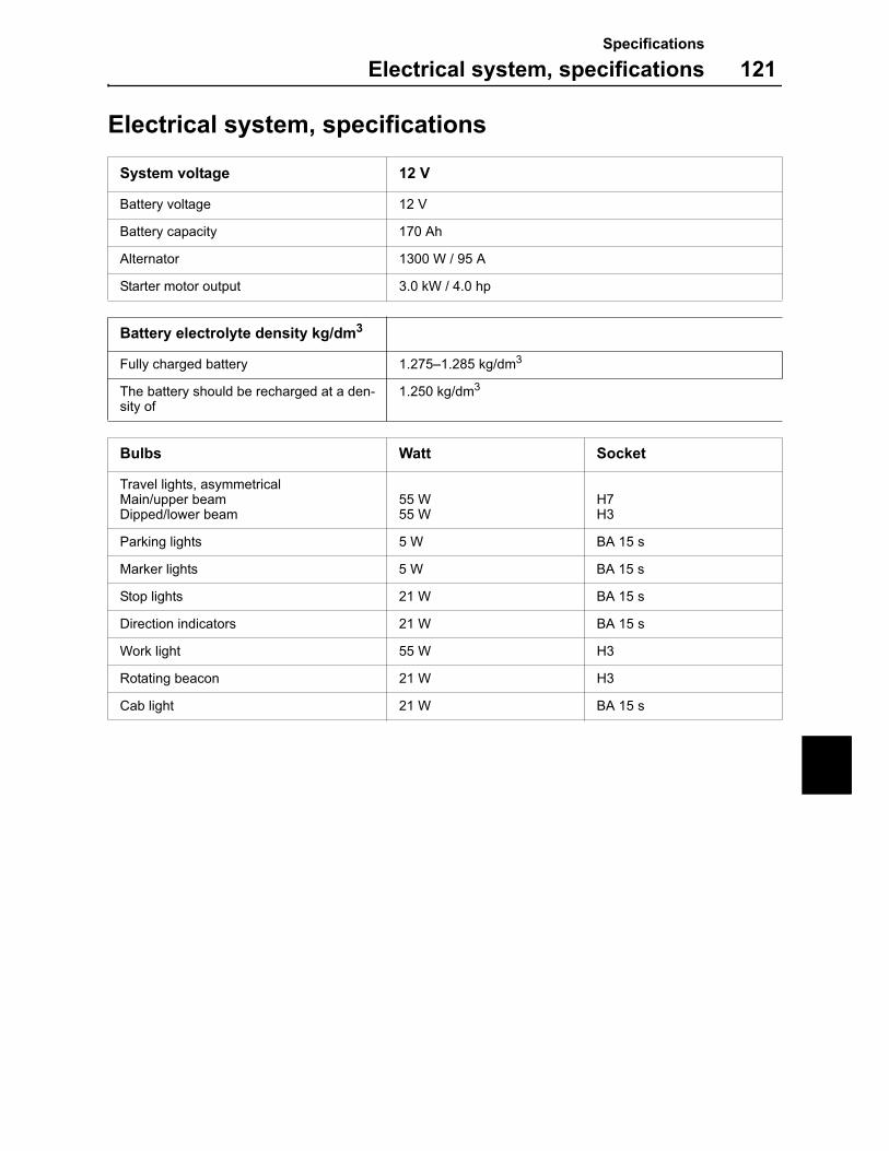
Specifications
Electrical system, specifications 121
Electrical system, specifications
System voltage 12 V
Battery voltage 12 V
Battery capacity 170 Ah
Alternator 1300 W / 95 A
Starter motor output 3.0 kW / 4.0 hp
Battery electrolyte density kg/dm3
Fully charged battery 1.275–1.285 kg/dm3
The battery should be recharged at a den-sity of
1.250 kg/dm3
Bulbs Watt Socket
Travel lights, asymmetricalMain/upper beamDipped/lower beam
55 W55 W
H7H3
Parking lights 5 W BA 15 s
Marker lights 5 W BA 15 s
Stop lights 21 W BA 15 s
Direction indicators 21 W BA 15 s
Work light 55 W H3
Rotating beacon 21 W H3
Cab light 21 W BA 15 s
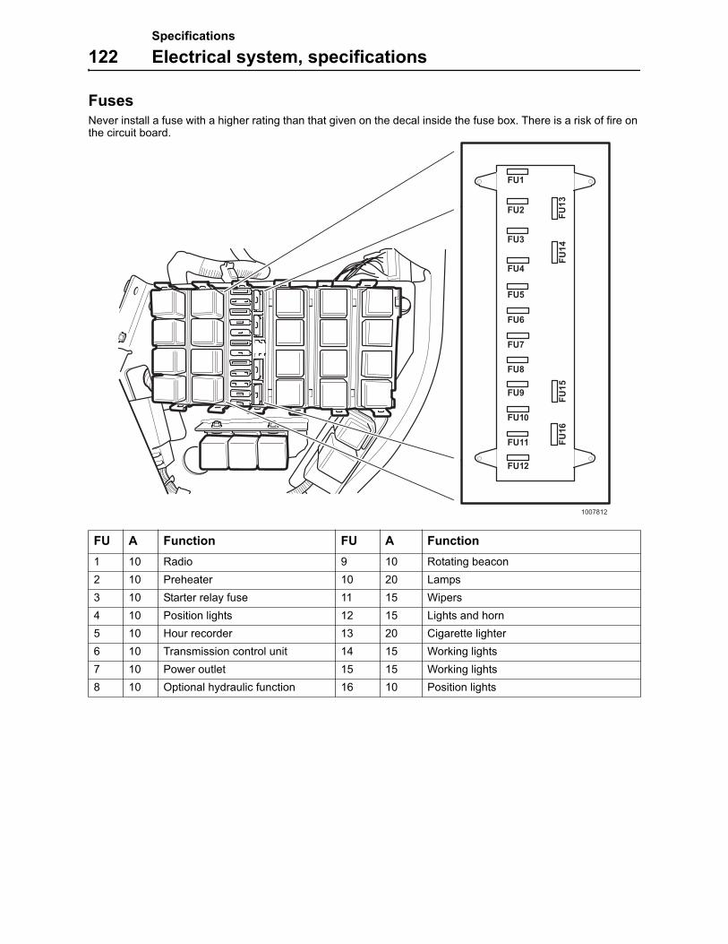
Specifications
122 Electrical system, specifications
FusesNever install a fuse with a higher rating than that given on the decal inside the fuse box. There is a risk of fire on the circuit board.
FU A Function FU A Function
1 10 Radio 9 10 Rotating beacon
2 10 Preheater 10 20 Lamps
3 10 Starter relay fuse 11 15 Wipers
4 10 Position lights 12 15 Lights and horn
5 10 Hour recorder 13 20 Cigarette lighter
6 10 Transmission control unit 14 15 Working lights
7 10 Power outlet 15 15 Working lights
8 10 Optional hydraulic function 16 10 Position lights
1007812
FU1
FU2
FU3
FU4
FU5
FU6
FU7
FU8
FU9
FU10
FU11
FU12
FU13
FU14
FU15
FU16
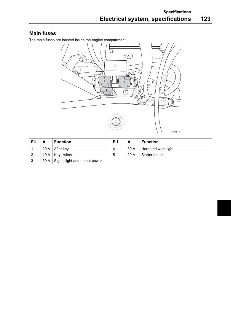
Specifications
Electrical system, specifications 123
Main fusesThe main fuses are located inside the engine compartment.
FU A Function FU A Function
1 20 A After key 4 30 A Horn and work light
2 40 A Key switch 5 20 A Starter motor
3 30 A Signal light and output power
1 23 4
5
1007814

Specifications
124 Electrical system, specifications
RelaysNever install relay with a higher rating than that given below.
RE A Function RE A Function
1 30 Starter 17 30 Axle lock
3 30 Neutral 18 30 Hydraulic oil filter pressure
7 30 Forward speed 19 30 Auxiliary 1
9 30 Gear box valve D 20 30 Auxiliary 2
10 30 Gear box valve C 21 30 Work light
11 30 Reverse speed 23 30 Blink relay
13 30 Low accumulator pressure 25 30 Axle lock
14 30 Pre accumulator 27 30 Plus after key
15 30 Pre accumulator indicator 28 30 Right blink light
16 30 Stop motor 29 30 Left blink light
1007815
1
3
27
9
10
7
11
14
15
17
25
18
19
20
28
29
21
162313

Specifications
Transmission, specifications 125
Transmission, specifications
Drop box, specifications
Transmission
Type Power shift transmission
Designation T12000
Torque converter, ratio 2:1
Number of gears forward/reverse 4/4
Pump flow at 33.4 r/s (2000 rpm) 53 litres (14 US gal) per minute
Gear-shifting system Electro hydraulic
Filter External spin on
Speed range forward/reverse
Gear
1st 5.1 km/h (3.1 mph)
2nd 11 km/h (6.8 mph)
3rd 22 km/h (13.7 mph)
4th 34 km/h (21.1 mph)
Transmission ratio
Gear Forward/reverse
1st 4.47
2nd 2.05
3rd 1.00
4th 0.66
Type Shaft drop box
Drop box ratio 1:1
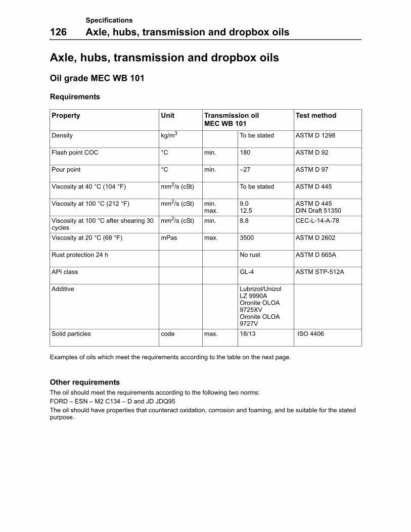
Specifications
126 Axle, hubs, transmission and dropbox oils
Axle, hubs, transmission and dropbox oils
Oil grade MEC WB 101
Requirements
Examples of oils which meet the requirements according to the table on the next page.
Other requirements
The oil should meet the requirements according to the following two norms:
FORD – ESN – M2 C134 – D and JD JDQ95
The oil should have properties that counteract oxidation, corrosion and foaming, and be suitable for the stated purpose.
Property Unit Transmission oilMEC WB 101
Test method
Density kg/m3 To be stated ASTM D 1298
Flash point COC °C min. 180 ASTM D 92
Pour point °C min. –27 ASTM D 97
Viscosity at 40 °C (104 °F) mm2/s (cSt) To be stated ASTM D 445
Viscosity at 100 °C (212 °F) mm2/s (cSt) min.max.
9.012.5
ASTM D 445DIN Draft 51350
Viscosity at 100 °C after shearing 30 cycles
mm2/s (cSt) min. 8.8 CEC-L-14-A-78
Viscosity at 20 °C (68 °F) mPas max. 3500 ASTM D 2602
Rust protection 24 h No rust ASTM D 665A
API class GL-4 ASTM STP-512A
Additive Lubrizol/UnizolLZ 9990AOronite OLOA 9725XVOronite OLOA 9727V
Solid particles code max. 18/13 ISO 4406
Specifications
Axle, hubs, transmission and dropbox oils 127
Examples of oils which meet the requirements according to the table on the previous page.
The following oils are approved provided the oil contains additive Lubrizol LZ9990A (also appears under the name Unizol).
Oil company Trade name
Q8 Q8 T2200
MOBIL MOBILFLUID 424
ESSO TORQUE FLUID 56
SOLENE INDUSTRIAL LUBRICANT SOLENE TRACTELF CH-5
STATOIL TRANSWAY WB
AGROL AGROL HYBRAN
ARAL ARAL FLUID HGS
TEXACO TEXACO TEXTRAN TDH PREMIUM
VALVOLINE VALVOLINE UNITRAC
ELF TRACTELF CH-5
OMV AS OMV AUSTROMATIC IGB
FINA TRANSFLUID JD, 10W-30
AVIA HYDROFLUID JD, 10W-30
CALTEX TEXTRAN TDH PREMIUM
DELTA SPECIAL UTTO 170
TOTAL TRANSMISSION MP
PANOLIN AG PANOLIN HMO 324
PETROBAS LUBRAX UNITRACTOR
Oil company Trade name
FUCHS FUCHS RENEGEAR HYDRA MC- ZF 20W/40
CASTROL CASTROL POWERTRANS
SHELL DONAX TD or FT/TD
BP BP TRACTRAN 9
BP HYDRAULIKÖLE TF-JD
ELF ELF TRACTELF BF12

Specifications
128 Axles, specifications
Axles, specifications
Front and rear axle
Front and rear axle hub
Type Drive/steer axle with external planetary reduction in the hub
Total gear ratio 1:23.25
Hub reduction gear ratio 1:6.00
Number of satelites 4

Specifications
Brakes/steering system, specifications 129
Brakes/steering system, specifications
Service brakes
Service brakes, type Single circuit, oil immersed brakes. The brakes are hydraulically operated.
Number of discs per axle, front/rear 8
Number of brake counter discs per axle, rear
10
Brake friction area per wheel 1174.8 cm2
Brake disc thickness, min. 4.35–4.45 mm (0.171–0.175 in)
Brake disc thickness, new 4.75–4.85 mm (0.187–0.191 in)
Counter discs thickness, new 2.60–2.70 mm (0.102–0.106 in)
Maximum operating pressure 50 bar (725 psi)
Parking brake
Parking brake, type Internal SAHR (Spring Applied, Hydraulic Released). Located on the front axle.
Brake friction area per wheel 1174.8 cm2
Steering system
Type Powered Orbitol
Number of steering wheel revolutions, total 3.5
Steering angle 45 degree steering angle
Turning radius curb–curb 3.9 m (12 ft 11 in)

Specifications
130 Tire combination chart, specifications
Tire combination chart, specificationsIMPORTANT! Use the same tires for front and rear. Do not mix tire sizes on the machine.
Size Pressure Manufacturer
Tire: 13x24Rim: 24x9
448 kPa4.5 bar65 psi
TITAN Tires
Tire: 13x24 Foam filledRim: 24x9
TITAN Tires
Tire: 15.5x25Rim: 25x13
448 kPa4.5 bar65 psi
TITAN Tires
Tire: 15.5x25 Foam filledRim: 25x13
TITAN Tires

Specifications
Cab/Open ROPS, specifications 131
Cab/Open ROPS, specifications
General
The cab is an enclosed cab with door and windows. The Open ROPS is an open cab without door or win-dows. Both the Cab and Open ROPS are tested according to FOPS and ROPS (see below for details) The Cab/Open ROPS is fitten onto the machine frame.
The Cab/Open ROPS is tested and approved as a protective cab according to ISO 3471-1994 and SAE J040-MAY 94 (ROPS), ISO 3449-1992 (FOPS) and ISO 6055-1997 (protective roof for rider trucks).
Cab/Open ROPS interior fittings and upholstery
Fire retardant (fire resistant) ISO3795-1989 and EN474-1.
Heating and ventilation (Cab only)
The cab is equipped with a ventilation system. The ventilation system is controlled by the operator by the control panel inside the cab.
Operator seat
The operator seat is equipped with a retractable lap seat belt. The standard seat belt is 50 mm (2 in) and the optional seat belt is 76.2 mm (3 in) wide.
The suspended seats meet the vibration standard ISO7096 class 3 and 4.
The seats meet the flammability standard FMVSS302.
Standard seat, type Adjustable seat, longitudinal and back-rest inclination, without suspension. Vinyl type.
Suspended seat, type (optional equip-ment)
Adjustable seat, longitudinal and back-rest inclination, with suspension. Vinyl or cloth type.
Sound level
The measuring of sound power level around the machine has been carried out according to 2000/14/EC with applicable appendices and measuring method according to EN 12053:2001.

Specifications
132 Hydraulic system, specifications
Hydraulic system, specifications
Hydraulic pump
Type Gear pump
Displacement 51.49 cm3/rev (3.14 in3/rev)
Direction of rotation Clockwise
Flow at 41.3 r/s (2500 rpm) 128.73 litres (33.98 US gal) per minute
Continuous pressure 25 MPa (250 bar) (3600 psi)
Intermittent pressure 27.5 MPa (275 bar) (4000 psi)
Peak pressure 31 MPa (310 bar) (4500 psi)
Valve block
Type Open centre load sensing valve with flow sharing functions
Maximum inlet flow 150 litres (40 US gal) per minute
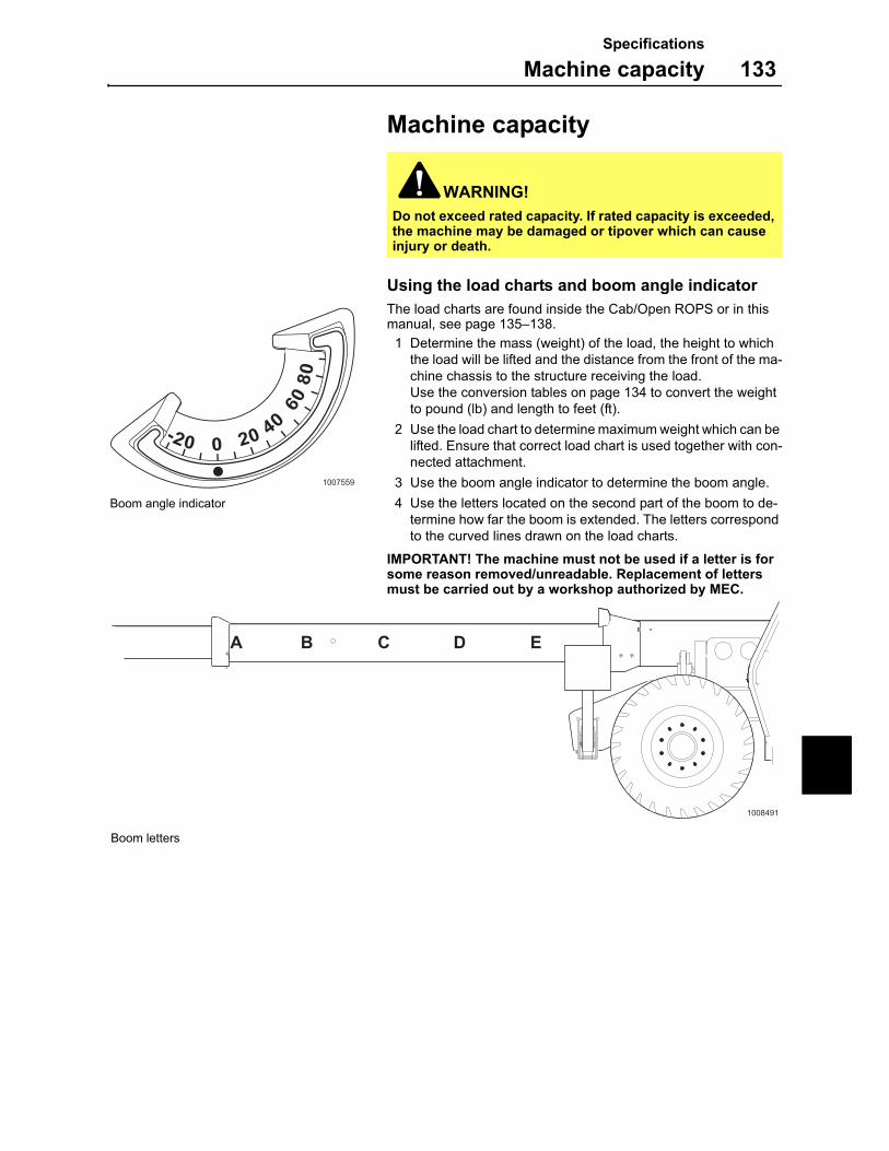
Specifications
Machine capacity 133
Machine capacity
Using the load charts and boom angle indicator
The load charts are found inside the Cab/Open ROPS or in this manual, see page 135–138.
1 Determine the mass (weight) of the load, the height to which the load will be lifted and the distance from the front of the ma-chine chassis to the structure receiving the load.Use the conversion tables on page 134 to convert the weight to pound (lb) and length to feet (ft).
2 Use the load chart to determine maximum weight which can be lifted. Ensure that correct load chart is used together with con-nected attachment.
3 Use the boom angle indicator to determine the boom angle.
4 Use the letters located on the second part of the boom to de-termine how far the boom is extended. The letters correspond to the curved lines drawn on the load charts.
IMPORTANT! The machine must not be used if a letter is for some reason removed/unreadable. Replacement of letters must be carried out by a workshop authorized by MEC.
WARNING!
Do not exceed rated capacity. If rated capacity is exceeded, the machine may be damaged or tipover which can cause injury or death.
-20 0 20 40
6080
II I I I I
II
I
II
II
1007559
Boom angle indicator
B C D EA
1008491
Boom letters

Specifications
134 Machine capacity
Measurement conversion tables
Length
Weight
Unit m in ft yd
m 1 39.37 3.2808 1.0936
in 0.0254 1 0.08333 0.02777
ft 0.3048 12 1 0.3333
yd 0.9144 36 3 1
Unit g kg oz lb
g 1 0.001 0.03527 0.0022
kg 1000 1 35.273 2.20459
oz 28.3495 0.02835 1 0.0625
lb 453.592 0.45359 16 1
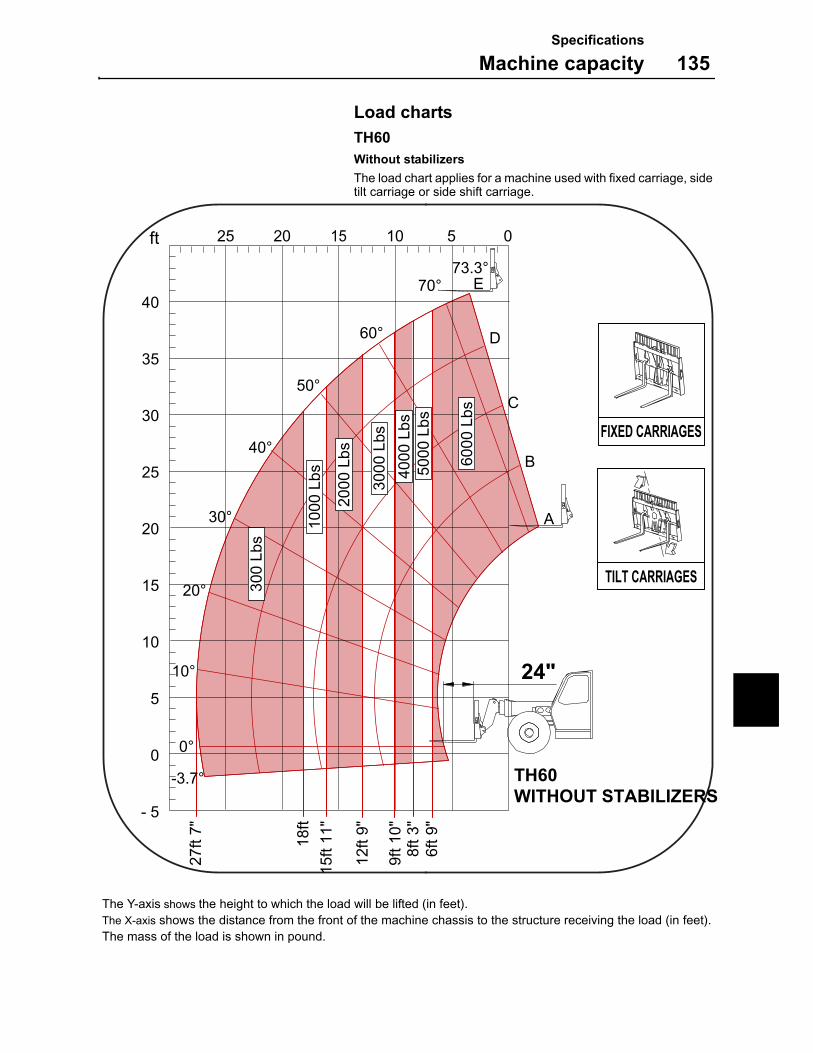
Specifications
Machine capacity 135
Load charts
TH60Without stabilizers
The load chart applies for a machine used with fixed carriage, side tilt carriage or side shift carriage.
The Y-axis shows the height to which the load will be lifted (in feet). The X-axis shows the distance from the front of the machine chassis to the structure receiving the load (in feet).The mass of the load is shown in pound.
40
35
30
25
20
15
10
5
0
- 5
25 20 15 10 05 ft
FIXED CARRIAGES
TILT CARRIAGES
TH60WITHOUT STABILIZERS
24"
27ft
7"
18ft
15ft
11"
12ft
9"
9ft 1
0"8f
t 3"
6ft 9
"
E
D
C
B
A
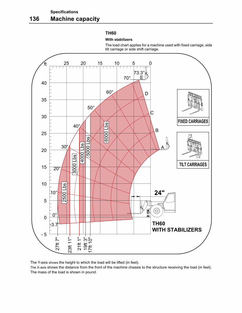
Specifications
136 Machine capacity
TH60With stabilizers
The load chart applies for a machine used with fixed carriage, side tilt carriage or side shift carriage.
The Y-axis shows the height to which the load will be lifted (in feet). The X-axis shows the distance from the front of the machine chassis to the structure receiving the load (in feet).The mass of the load is shown in pound.
40
35
30
25
20
15
10
5
0
- 5
25 20 15 10 05ft
FIXED CARRIAGES
TILT CARRIAGES
TH60WITH STABILIZERS
24"
27ft
7"
23ft
11"
21ft
1"
17ft
10"
19ft
3"
E
D
C
B
A
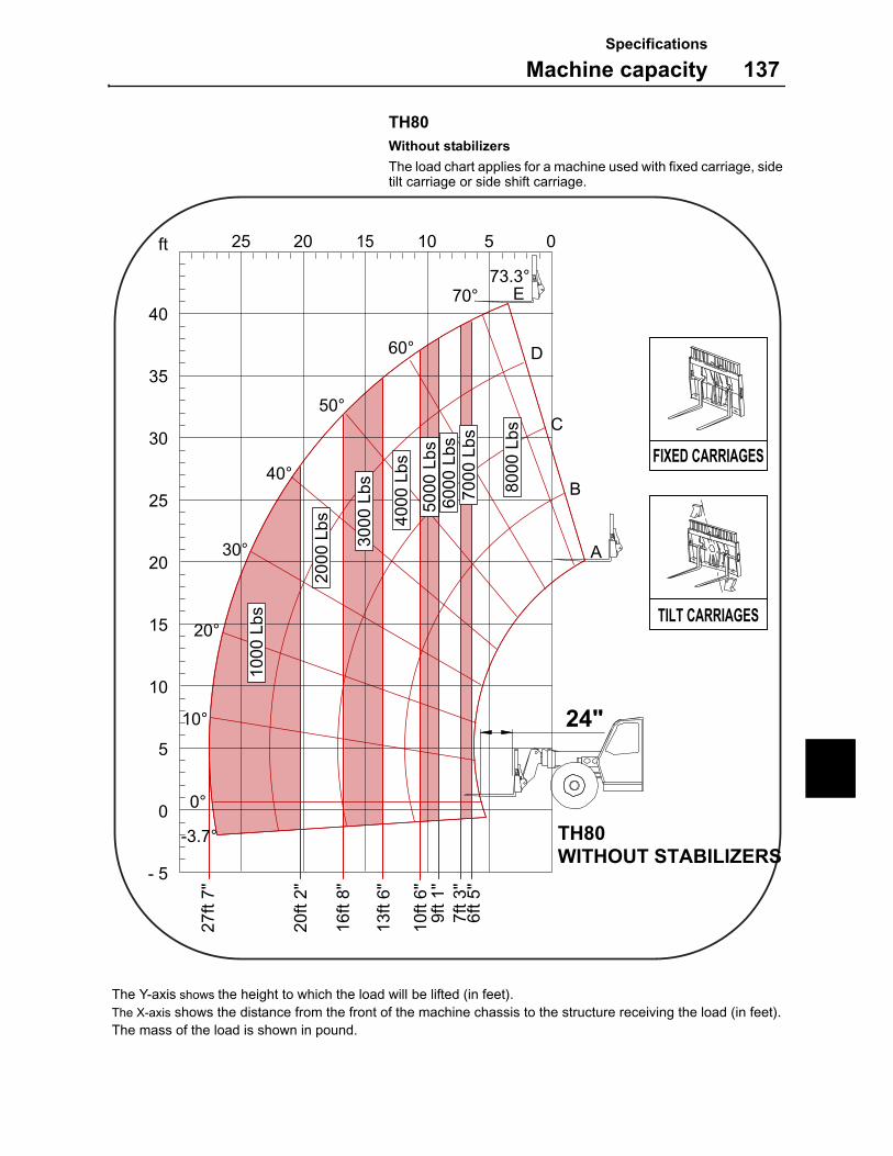
Specifications
Machine capacity 137
TH80Without stabilizers
The load chart applies for a machine used with fixed carriage, side tilt carriage or side shift carriage.
The Y-axis shows the height to which the load will be lifted (in feet). The X-axis shows the distance from the front of the machine chassis to the structure receiving the load (in feet).The mass of the load is shown in pound.
40
35
30
25
20
15
10
5
0
- 5
25 20 15 10 05ft
FIXED CARRIAGES
TILT CARRIAGES
TH80WITHOUT STABILIZERS
24"
27ft
7"
20ft
2"
16ft
8"
13ft
6"
9ft 1
"7f
t 3"
6ft 5
"
10ft
6"
E
D
C
B
A
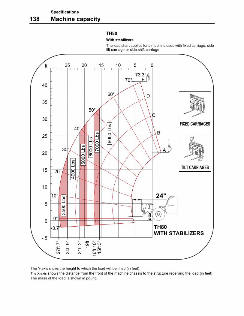
Specifications
138 Machine capacity
TH80With stabilizers
The load chart applies for a machine used with fixed carriage, side tilt carriage or side shift carriage.
The Y-axis shows the height to which the load will be lifted (in feet). The X-axis shows the distance from the front of the machine chassis to the structure receiving the load (in feet).The mass of the load is shown in pound.
40
ft
35
30
25
20
15
10
5
0
- 5
25 20 15 10 05
FIXED CARRIAGES
TILT CARRIAGES
TH80WITH STABILIZERS
24"
27ft
7"
24ft
9"
21ft
2"
16ft
10"
15ft
3"
19ft
E
D
C
B
A
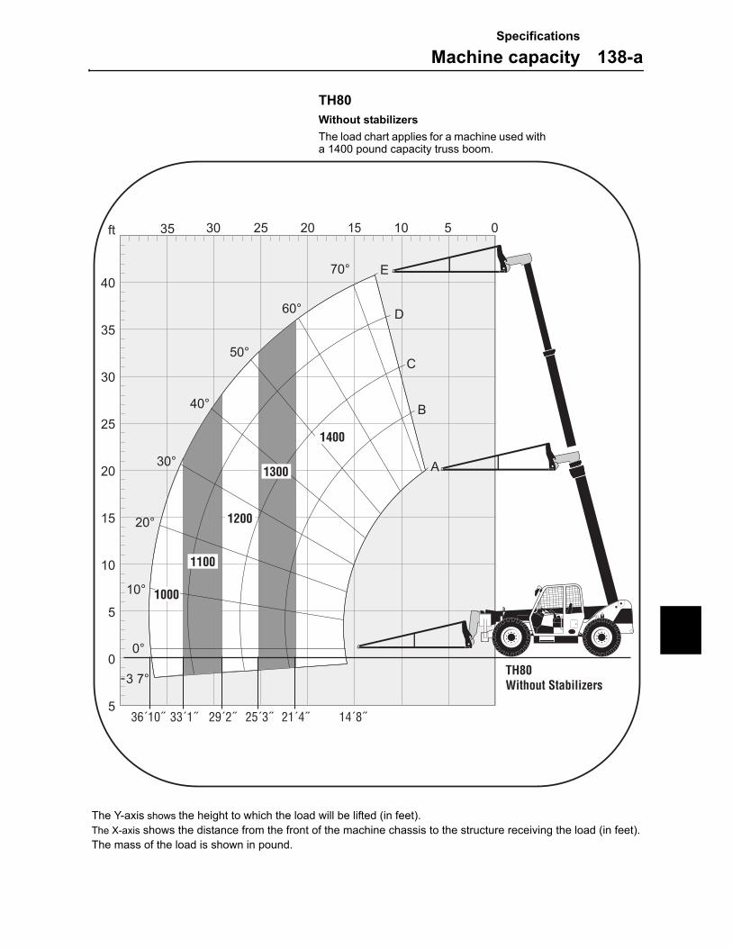
Specifications
Machine capacity 138-a
TH80Without stabilizersThe load chart applies for a machine used with a 1400 pound capacity truss boom.
The Y-axis shows the height to which the load will be lifted (in feet). The X-axis shows the distance from the front of the machine chassis to the structure receiving the load (in feet).The mass of the load is shown in pound.
14´8˝36´10˝ 33´1˝ 29´2˝ 21´4˝25´3˝
1000
1100
1200
1300
1400
TH80Without Stabilizers
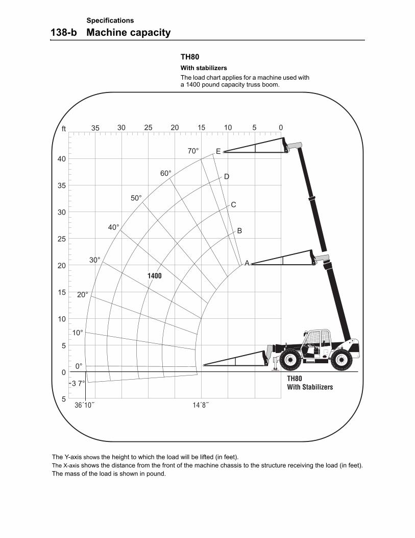
Specifications
138-b Machine capacity
TH80With stabilizersThe load chart applies for a machine used with a 1400 pound capacity truss boom.
The Y-axis shows the height to which the load will be lifted (in feet). The X-axis shows the distance from the front of the machine chassis to the structure receiving the load (in feet).The mass of the load is shown in pound.
14´8˝36´10˝
1400
TH80With Stabilizers
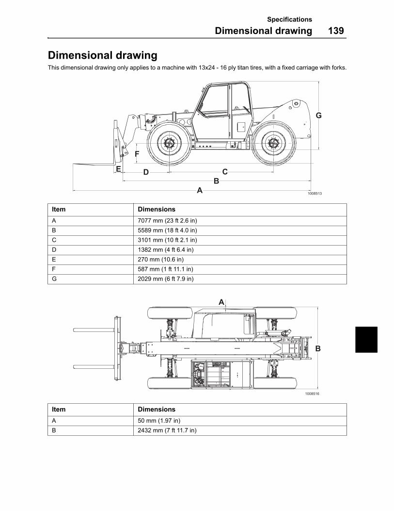
Specifications
Dimensional drawing 139
Dimensional drawingThis dimensional drawing only applies to a machine with 13x24 - 16 ply titan tires, with a fixed carriage with forks.
Item Dimensions
A 7077 mm (23 ft 2.6 in)
B 5589 mm (18 ft 4.0 in)
C 3101 mm (10 ft 2.1 in)
D 1382 mm (4 ft 6.4 in)
E 270 mm (10.6 in)
F 587 mm (1 ft 11.1 in)
G 2029 mm (6 ft 7.9 in)
Item Dimensions
A 50 mm (1.97 in)
B 2432 mm (7 ft 11.7 in)
AB
CDE
F
G
1008513
A
B
1008516
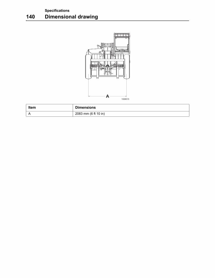
Specifications
140 Dimensional drawing
Item Dimensions
A 2083 mm (6 ft 10 in)
A1008515

Alphabetical index
141
Alphabetical indexAccidents .......................................................................37Accumulator ...................................................................64Air cleaner......................................................................87Alphabetical index........................................................141Arrival and delivery inspection .......................................79Attachment, connecting .................................................60Attachment, disconnecting.............................................59Attachments ...................................................................58Attachments, maintenance ..........................................107Axle breather, cleaning ..................................................99Axle hubs, checking oil level ..........................................97Axle, hubs, transmission and dropbox oils...................126Axles ..............................................................................97Axles, changing hub oil ..................................................99Axles, changing oil .........................................................98Axles, checking oil level .................................................97Axles, specifications.....................................................128Battery disconnect switch ..............................................91Battery, charging............................................................92Battery, maintenance .....................................................91Battery, safety rules .......................................................91Before service read........................................................72Boom chains, checking ................................................102Boom wear pads ..........................................................101Boom wear pads, checking..........................................101Boom wear pads, greasing lanes.................................102Boom............................................................................101Boom, manual lowering .................................................55Brake system ...............................................................100Brake test .......................................................................49Brakes/steering system, specifications .......................129Braking...........................................................................49Cab/Open ROPS .........................................................104Cab/Open ROPS, specifications..................................131Center instrument panel.................................................20Center of gravity.............................................................40Changing steer modes...................................................46Check list after fire .........................................................77Connecting hydraulic couplings .....................................65Controls..........................................................................29Coolant...........................................................................88Coolant, changing ..........................................................89Coolant, checking ..........................................................88Cooling system ..............................................................88Delivery Instructions.......................................................79Dimensional drawing....................................................139Disconnecting hydraulic couplings.................................65Drop box oil level, checking ...........................................96Drop box oil, changing ...................................................96Drop box ........................................................................96Drop box, specifications...............................................125Electrical system ............................................................91Electrical system, specifications...................................121Engine oil filter, replacing...............................................82Engine oil, changing.......................................................81Engine oil, checking .......................................................81Engine............................................................................81Engine, specifications ..................................................120Fire prevention measures ..............................................74Fixed carriage ..............................................................107Fluoro-carbon rubber .....................................................76Foreword..........................................................................1Fork carriages ................................................................62Front and rear axle hub................................................128Front and rear axle.......................................................128Fuel filters ......................................................................83Fuel system....................................................................83Fuel system, bleeding ....................................................84Fuel system, draining.....................................................85Fuel tank ........................................................................83
Fuses and relays ........................................................... 93Fuses........................................................................... 122Gear shifting .................................................................. 48Headlamps, adjusting .................................................... 93Hydraulic couplings........................................................ 65Hydraulic system ......................................................... 105Hydraulic system, changing oil .................................... 105Hydraulic system, checking oil level ............................ 105Hydraulic system, replacing breather filter................... 106Hydraulic system, replacing oil filter ............................ 106Hydraulic system, specifications.................................. 132Hydraulic system, warming up....................................... 44Identification numbers...................................................... 2Information and warning decals....................................... 9Instrument panels .......................................................... 17Intended use.................................................................... 5Left instrument panel ..................................................... 18Leveling the machine frame........................................... 47Load charts .................................................................. 135Lubrication and service chart....................................... 109Lubrication and service chart....................................... 110Lubrication points......................................................... 114Machine capacity ......................................................... 133Machine operator safety ................................................ 37Machine view................................................................... 7Main fuses ................................................................... 123Manual gear shifting ...................................................... 48Measurement conversion tables.................................. 134Measures before operating............................................ 42Off-road operation.......................................................... 66Oil grade MEC WB 101 .............................................. 126Operating instructions.................................................... 35Operating techniques..................................................... 57Operator comfort............................................................ 34Operator duties .............................................................. 36Operator seat................................................................. 34Other controls ................................................................ 29Paintwork maintenance ................................................. 79Pallet forks ..................................................................... 61Pallet forks, operating .................................................... 61Parking brake, manual release...................................... 54Parking........................................................................... 51Presentation..................................................................... 5Primary filter, maintenance and replacement ................................................................... 87Product plates.................................................................. 8Radiator and oil cooler, cleaning ................................... 90Recommended lubricants ............................................ 117Relays.......................................................................... 124Right instrument panel................................................... 26Rubber and plastics ....................................................... 77Running-in ..................................................................... 35Safety regulations............................................................ 1Safety rules when operating .......................................... 36Safety when servicing.................................................... 69Secondary filter, replacing ............................................. 87Service and maintenance .............................................. 79Service capacities and lubricants ................................ 119Service points ................................................................ 80Service position 1 .......................................................... 70Service position 2 .......................................................... 71Service positions............................................................ 69Service programme ....................................................... 79Side shift carriage........................................................ 108Side tilt carriage........................................................... 107Signalling diagram ......................................................... 67Specifications............................................................... 117Starting engine............................................................... 43Starting with booster battery .......................................... 92Steering ......................................................................... 45Stopping the machine.................................................... 50Symbol key .................................................................. 109

Alphabetical index
142
Table of contents .............................................................3The USA Federal Clean Air Act .....................................14Tire combination chart, specifications..........................130Tires .............................................................................103Towing ...........................................................................52Transmission oil level, checking.....................................94Transmission..................................................................94Transmission, changing oil ............................................94Transmission, replacing oil filter.....................................95Transmission, specifications ........................................125Transporting the machine ..............................................56Travelling and operating on slopes ................................39Turbocharger .................................................................86Wheel nuts, check-tightening.......................................103Window washer reservoir (cab only), front and rear ....104Working in water areas ..................................................66Working on painted surfaces ........................................76Working within dangerous areas....................................38