Embed Size (px)
Citation preview

Mana Drag Racing Strip Improvements Phase 2 Electrical Upgrades Kauai, Hawaii Job No. 500CK30B Addendum No. 2 Page 1 of 3
State of Hawaii DEPARTMENT OF LAND AND NATURAL RESOURCES
ENGINEERING DIVISION 1151 Punchbowl Street, Room 221
Honolulu, Hawaii 96813
ADDENDUM NO. 2
TO
Job No. 500CK30B MANA DRAG RACING STRIP IMPROVEMENTS PHASE 2
ELECTRICAL IMPROVEMENTS Kekaha, Kauai, Hawaii
______________
This addendum as issued shall become part of the Contract Documents for the subject project. The bid documents, plans, and specifications shall be amended as follows: GENERAL INFORMATION Pre-Bid Conference Sign-In Sheet enclosed as a part of this addendum. PROPOSAL (PDF copies of the revised proposal can be downloaded from the HIePRO website.) Proposal – DELETE Pages P-2 to P-7 in its entirety and REPLACE with the attached revised Pages P-2 to P-7. SPECIFICATION (PDF copies of the revised sections can be downloaded from the HIePRO website.) Enclosed revised sections shall replace their respective existing sections in its entirety.
1. Section 01567 – Environmental Protection 2. Section 16500 – Lighting
CONSTRUCTION PLANS None

Mana Drag Racing Strip Improvements Phase 2 Electrical Upgrades Kauai, Hawaii Job No. 500CK30B Addendum No. 2 Page 2 of 3
QUESTIONS AND CLARIFICATIONS Pre-Bid Conference:
1. What is the biological monitoring allowance for? a. Response: Item 28 and 29 are for the biological and archaeological monitoring
required during construction activities.
2. Who hires and oversees the sub-contractor for the biological and archaeological monitoring, the Contractor or Consultant?
a. Response: The Contractor is responsible for the hiring and retaining the archaeological and biological monitors.
3. If the contractor hires the biological and archaeological monitor do they hire a specific
sub-consultant? a. Response: The Contractor may select any sub-consultant qualified to do the
work.
4. What is the scope of work for the archaeological and biological monitors? a. Response: Archaeological monitoring shall be done in accordance with the
specifications and Archaeological Monitoring Plan prepared for the project. Biological monitoring shall be done in accordance with the specifications.
Miscellaneous Questions:
1. If a contractor is awarded a project based on having the apprenticeship program preference do they need to be a party to an apprenticeship agreement for each apprenticeable trade they will employ on the project?
a. Response: The Contractor is required to be a party to an apprenticeship agreement for every apprenticeable trade they will employ on the project as specified in the Proposal section of the specifications, section 103-55.6 of the Hawaii Revised Statutes (HRS), and the Department of Accounting and General Services (DAGS) Office of the Comptroller Memoranda (No. 2011-25).
2. If a contractor is awarded a project based on having the apprenticeship program
preference do they need to have an apprentice on the job for each of the listed trades? a. Response: The Contractor is not required to have an apprentice on the job for
each of the listed trades but shall meet all the requirements of the apprenticeship program preference as indicated in the Proposal section of the specifications, section 103-55.6 of the HRS, and the DAGS Office of the Comptroller Memoranda (No. 2011-25).
3. Per Notice to Bidders, the estimated cost of construction is $250,000 to $500,000. Does
that mean a $500,000 bid bond is enough? Does the bid bond need to be enough to include all additives?
a. Response: The Contractor shall provide a bid bond of sufficient size to cover the base bid and additives awarded as a part of the project as required.

Agenda
Pre –Bid Conference For
JOB NO. 500CK30B
MANA DRAG RACING STRIP IMPROVEMENTS PHASE 2 ELECTRICAL UPGRADES KEKAHA, KAUAI, HAWAII
Date: May 17, 2016 @ 10:00 a.m. Location: Mana Drag Racing Strip 1. Introductions 2. Brief Description of Project and Scope The work shall generally consist of electrical upgrades including the construction of
new overhead utility lines, track lighting, and other electrical equipment such as transformers, electric meters, pull boxes, and underground conduits.
Bid Opening is on June 2, 2016 at 2:00 p.m. Last day to submit questions and substitution requests is on May 21, 2016. 3. Electrical Upgrades and Miscellaneous Items KIUC Service: The contractor shall coordinate with KIUC for the installation of new
overhead utility lines.
Track Lighting: Substitution requests are required for track lighting systems not specified in Section 16531 – Track Lighting.
Structural Design Requirements: Project specific track lighting foundations shall be
designed by a structural engineer licensed in Hawaii. Biological/Archeological Monitoring: Biological and Archeological monitors shall
be present on the project site during construction and earth moving activities including all work to be completed by KIUC.
Flood Elevation Certificate: The Contractor shall submit a county approved flood
elevation certificate as a part of the project. Electrical Permit: Plans/forms shall be submitted to the County of Kauai Building
Division for Electrical Permit. The contractor shall coordinate with the Garden Isle Racing Association for onsite
staging and stockpiling.

4. Questions
Note: All answers and comments are unofficial, the official answers will be distributed in an Addendum. Please make sure your question are heard and written down so we to make sure it is included in the addendum.
5. Walk Through of Project Area.


MANA DRAGE RACING STRIP IMPROVEMENTS PHASE 2
ELECTRICAL UPGRADES
Job No. 500CK30B
ITEM
NO. DESCRIPTION UNIT PRICE TOTAL
BASIC BID
1 Mobilization and Demobilization, including
demolition, restoration, cleanup, permit fees,
and all incidentals (Not to exceed 10% of the
subtotal Basic Bid) $ $
2 Temporary Erosion and Sediment Control, in
place complete $ $
3 Construction Layout, including survey before and
after site improvements and flood certification
$ $
4 1 EA Switchboard Concrete Equipment Pad $ $
5 1 EA Transformer Concrete Equipment Pad $ $
6 1 EA Meter Enclosure Concrete Equipment Pad $ $
7 4 EA Stanchions $ $
8 1 EA 3' X 5' Handhole $ $
9 3 EA 2' X 4' Handhole (EHH‐10 to EHH‐11, EHH‐20) $ $
10 1 EA NEMA 4X 316 Stainless Steel Enclosure (Meter
Enclosure) $ $
11 1 EA NEMA 1 Integrated Switchboard $ $
12 1 EA NEMA 4X 316 Stainless Steel Enclosure
(Main Switchboard Enclosure) $ $
13 1 EA NEMA 4X 316 Stainless Steel Enclosure (Lockable
Cabinet) $ $
14 2 EA Push Button Controls $ $
15 30 L.F. 4" PVC Duct, Schedule 40 $ $
16 850 L.F. 2" PVC Duct, Schedule 80 $ $
Electrical Improvements
ESTIMATED
QUANTITY
General Site Improvements
L.S.
L.S.
L.S.
P‐2 Addendum No. 2

MANA DRAGE RACING STRIP IMPROVEMENTS PHASE 2
ELECTRICAL UPGRADES
Job No. 500CK30B
ITEM
NO. DESCRIPTION UNIT PRICE TOTAL
ESTIMATED
QUANTITY
17 175 L.F. 1" PVC Duct, Schedule 80 $ $
18 20 L.F. #500kcmil Wire $ $
19 20 L.F. #1/0 Wire $ $
20 2 EA Receptacle, Duplex, GFCI, Weather Proof, 120V
$ $
21 115 C.Y. Trenching and Backfill for Direct Buried Electrical
Conduit $ $
22 20 C.Y. Trenching and Backfill for Concrete Encased
Electrical Conduit $ $
23 8 C.Y. Concrete for Electrical Encasement $ $
24 Project Sign $ $
25 Field Office $ 14,000.00
26 KIUC Customer Contribution $ 200,000.00
27 KIUC Underground Service Fee $ 40,000.00
28 Archaeological Monitoring $ 48,000.00
29 Biological Monitoring $ 14,000.00
$
L.S.
* Allowance
* Allowance
* Allowance
* Allowance
* Allowance
**********************************************************************************
TOTAL SUM BASIC BID
(Items 1 thru 29, Inclusive)
P‐3 Addendum No. 2

MANA DRAGE RACING STRIP IMPROVEMENTS PHASE 2
ELECTRICAL UPGRADES
Job No. 500CK30B
ITEM
NO. DESCRIPTION UNIT PRICE TOTAL
ESTIMATED
QUANTITY
ADDITIVE NO. 1
30 8 EA 2' X 4' Handhole; 625 LF 2" PVC Duct; Excavation
and Backfill (EHH‐10 to EHH‐2B); Temporary
Erosion Control; and all incidentals, in place
complete $ $
31 1 EA 2' X 4' Handhole; 300 LF 2" PVC Duct; Excavation
and Backfill (EHH‐2B to EHH‐2A); Temporary
Erosion Control; and all incidentals, in place
complete $ $
32 1 EA 3900 LF of #4/0 Wire, 1300 LF of #2 Wire, and all
incidentals, in place complete (Switch Board to
EHH‐2B) $ $
$
ADDITIVE NO. 2
33 Electronic Scoreboard, including all incidentals, in
place complete $ 60,000.00
$
ADDITIVE NO. 3
34 1 EA Pole‐Mounted MH Track Lighting Luminaire, Pole,
Precast Base, PVC Ducts, Wiring, and all
appurtenances, in place complete (P2) $ $
35 1 EA 4200 LF of #4/0 Wire, 1400 LF of #2 Wire, and all
incidentals, in place complete (Switch Board to
EHH‐2A) $ $
$
* Allowance
TOTAL SUM ADDITIVE NO.2
(Item 33, Inclusive)
**********************************************************************************
Track Lighting System (P2)
TOTAL SUM ADDITIVE NO.3
(Item 34 thru 35, Inclusive)
**********************************************************************************
Wiring (Switchboard to EHH‐19)
Handhole and Conduit (EHH‐9 to EHH‐2A)
TOTAL SUM ADDITIVE NO.1
(Item 30 thru 32, Inclusive)
**********************************************************************************
P‐4 Addendum No. 2

MANA DRAGE RACING STRIP IMPROVEMENTS PHASE 2
ELECTRICAL UPGRADES
Job No. 500CK30B
ITEM
NO. DESCRIPTION UNIT PRICE TOTAL
ESTIMATED
QUANTITY
ADDITIVE NO. 4
36 1 EA Pole‐Mounted MH Track Lighting Luminaire, Pole,
Precast Base, PVC Ducts, Wiring, and all
appurtenances, in place complete (P4) $ $
$
ADDITIVE NO. 5
37 1 EA 2' X 4' Handhole; 320 LF 2" PVC Duct; Excavation
and Backfill (EHH‐2A to EHH‐1); Temporary
Erosion Control; and all incidentals, in place
complete $ $
$
ADDITIVE NO. 6
38 1 EA 2' X 4' Handhole; 465 LF 2" PVC Duct; 465 LF 1
1/2" PVC Conduit; Excavation and Backfill (EHH‐
11 to EHH‐12); Temporary Erosion Control; and
all incidentals, in place complete
$ $
39 1 EA 2' X 4' Handhole; 630 LF 2" PVC Duct; 100 LF 1
1/2" PVC Conduit; Excavation and Backfill (EHH‐
12 to EHH‐13 and Tower); Temporary Erosion
Control; and all incidentals, in place complete
$ $
Handhole and Conduit (EHH‐11 to EHH‐19)
**********************************************************************************
Track Lighting System (P3)
TOTAL SUM ADDITIVE NO.4
(Item 36, Inclusive)
**********************************************************************************
Handhole and Conduit (EHH‐2A to EHH‐1)
TOTAL SUM ADDITIVE NO.5
(Item 37, Inclusive)
P‐5 Addendum No. 2

MANA DRAGE RACING STRIP IMPROVEMENTS PHASE 2
ELECTRICAL UPGRADES
Job No. 500CK30B
ITEM
NO. DESCRIPTION UNIT PRICE TOTAL
ESTIMATED
QUANTITY
40 5 EA 2' X 4' Handhole; 630 LF 2" PVC Duct; Excavation
and Backfill (EHH‐13 to EHH‐18); Temporary
Erosion Control; and all incidentals, in place
complete $ $
41 1 EA 2' X 4' Handhole; 430 LF 2" PVC Duct; Excavation
and Backfill (EHH‐18 to End); Temporary Erosion
Control; and all incidentals, in place complete
$ $
$
ADDITIVE NO. 7
42 4,800 LF #4/0 Wire $ $
43 1,600 LF #2 Wire $ $
$
ADDITIVE NO. 8
44 10,200 LF #4/0 Wire $ $
45 3,400 LF #2 Wire $ $
46 1,800 LF #12 Wire $ $
$
ADDITIVE NO. 9
47 9 EA Pole‐Mounted MH Track Lighting Luminaire, Pole,
Precast Base, PVC Ducts, Wiring, and all
appurtenances, in place complete (P1, P3, P5 to
P11) $ $
$
TOTAL SUM ADDITIVE NO.6
(Item 38 thru 41, Inclusive)
**********************************************************************************
Wiring (Switchboard to EHH‐1)
TOTAL SUM ADDITIVE NO.7
(Item 42 thru 43, Inclusive)
**********************************************************************************
Wiring (Switchboard to EHH‐19)
TOTAL SUM ADDITIVE NO.8
(Item 44 thru 46, Inclusive)
**********************************************************************************
Track Lighting System (P1, P3, P5 to P11)
TOTAL SUM ADDITIVE NO.9
(Item 47 Inclusive)
P‐6 Addendum No. 2

MANA DRAGE RACING STRIP IMPROVEMENTS PHASE 2
ELECTRICAL UPGRADES
Job No. 500CK30B
ITEM
NO. DESCRIPTION UNIT PRICE TOTAL
ESTIMATED
QUANTITY
ADDITIVE NO. 10
48 8 EA Pole‐Mounted MH Track Lighting Luminaire, Pole,
Precast Base, PVC Ducts, Wiring, and all
appurtenances, in place complete (P12 to P19)
$ $
$
ADDITIVE NO. 11
49 4 EA Additional Erosion Control $ $
50 4 EA 2' X 4' Handhole (EHH‐21 to EHH‐23) $ $
51 1,300 L.F. 2" PVC Duct, Pull String, End Cap $ $
52 80 C.Y. Excavation and Backfill for Electrical Work,
including disposal, including all incidentals $ $
$
Track Lighting System (P12 to P19)
TOTAL SUM ADDITIVE NO.10
(Item 48 Inclusive)
**********************************************************************************
Spectator Area
TOTAL SUM ADDITIVE NO.11
(Items 49 thru 52, Inclusive)
**********************************************************************************
P‐7 Addendum No. 2

Environmental Protection 01567-1 Addendum No. 2
SECTION 01567
ENVIRONMENTAL PROTECTION
PART 1 – GENERAL 1.1 DESCRIPTION OF WORK
A. Furnish all labor, material and equipment and perform all work required for the prevention
of environmental pollution during and as the result of construction operations under this contract.
B. This Section contains general specifications pertaining to the prevention of environmental pollution and disturbance as a result of construction operations under this contract and shall be maintained until completion of the contract and become a part of the work of all other Sections as applicable. The requirements of this Section take precedence over conflicting or contradictory provisions of other Sections.
C. The work in this Section shall include the following:
1. Obtain all permits required by the State Department of Health.
2. Provide all air and water quality testing and monitoring work required by the
permits during construction.
3. Provide the facilities, equipment, and structural controls for minimizing adverse impacts upon the environment during the construction period.
D. Related Work Described Elsewhere: Additional information pertaining to pollution control
work including erosion control and temporary grassing will be found in various specific technical sections.
1.2 DEFINITIONS A. For the purpose of this specification, Environmental Pollution is defined as the presence of
chemical, physical, or biological elements or agents which: 1. Adversely affect human/animal health or welfare.
2. Unfavorably alter ecological balances important to human/animal life.
3. Affect other species of importance to man.
4. Degrade the utility of the environment for its normal daily function, for aesthetic,
and for recreational purposes.
B. The control of environmental pollution requires consideration of air, water and land, and involves noise control, solid waste management, and management of other pollutants.

Environmental Protection 01567-2 Addendum No. 2
1.3 GENERAL REQUIREMENTS
A. Comply with all applicable Federal and State laws, including the latest Hawaii Public
Health regulations, local laws and regulations concerning pollution control and abatement. B. The Contractor shall become familiar with the latest requirements of the National
Pollutant Discharge Elimination System (NPDES) Permit and all other necessary permits to discharge water to State receiving waters, into storm drainage system and into sanitary sewer system prior to bidding on this project. The Contractor will apply for appropriate NPDES permits required by the State Department of Health (DOH). The Contractor shall prepare and submit a written site-specific construction BMP Plan to DOH thirty (30) calendar days prior to constructions as required.
C. Notification: The Engineer will notify the Contractor in writing of any non-compliance
with the foregoing provisions and the action to be taken. Such notice, when delivered to the Contractor or his authorized representative at the site of the work, shall be deemed sufficient for the purpose of notification. After receipt of such notice, the Contractor shall immediately take corrective action. If the Contractor fails or refuses to comply promptly, the Engineer may issue an order stopping all or part of the work until satisfactory corrective action has been taken. No part of the time lost due to any such stop orders shall be made the subject of a claim for extension of time or for excess costs or damages by the Contractor unless it was later determined that the Contractor was in compliance.
D. Sub-Contractor: Compliance with the provisions of this Section by subcontractors will be
the responsibility of the Contractor.
1.4 APPLICABLE REGULATIONS
A. In order to provide for abatement and control of environmental pollution arising from the construction activities of the Contractor and his subcontractors in the performance of this contract, the work performed shall comply with the intent of the applicable Federal, State and local laws and regulations concerning environmental pollution control and abatement, including, but not limited to, the following regulations:
1. State of Hawaii, Department of Health, Administrative Rules, Chapter 55, WATER
POLLUTION CONTROL; Chapter 54, WATER QUALITY STANDARDS. 2. State of Hawaii, Department of Health, Administrative Rules, Chapter 59,
AMBIENT AIR QUALITY; Chapter 60.1, AIR POLLUTION CONTROL LAW. 3. State of Hawaii, Department of Health, Administrative Rules, Chapter 42,
VEHICULAR NOISE CONTROL; Chapter 46, COMMUNITY NOISE CONTROLS.
4. Other regulations as noted on the drawings.

Environmental Protection 01567-3 Addendum No. 2
PART 2 – PRODUCTS (NOT USED)
PART 3 – EXECUTION
3.1 LAND RESOURCES PROTECTION
A. General: Unless otherwise indicated on the drawings, existing land resources within the property lines and outside the limits of permanent work performed under this contract shall be preserved in their present condition or be restored to a condition after completion of construction that will appear to be natural and not detract from the appearance of the project. Insofar as possible, confine construction activities to areas defined by the plans or specifications.
B. Restoration of Damage: Restore all existing improvements, trees or other landscape feature scarred or damaged by the Contractor’s equipment or operations to its original condition at the Contractor’s expense. The Engineer will decide what method of restoration shall be used and whether damaged trees or other landscape feature shall be treated and healed or removed from the site and replaced with new.
C. Location of Storage and Construction Facilities: The Contractor’s storage and other temporary construction buildings required temporarily in the performance of the work shall be located on the project property. The location shall be upon cleared portions of the job site or areas to be cleared, as indicated on the plans and approved by the Engineer.
D. Post-Construction Clean-Up: Obliterate all signs of temporary construction facilities such as work areas, structures, foundations of temporary structures, stockpiles of excess or waste materials, or any other vestiges of construction as directed by the Engineer. No separate payment will be made for post-construction cleanup or obliteration and all cost thereof shall be considered a portion of the Contract Price, except as otherwise provided for in the Contract Documents.
3.2 BURNING
No materials may be burned within the contract area at any time within the contract period.
3.3 WATER POLLUTION
A. General
1. The Contractor shall not deposit at the site or in its vicinity, solid waste or
discharge liquid waste, such as fuels, lubricants, bituminous waste, untreated sewage and other pollutants, which may contaminate any surface water or ground water.
2. Care shall be taken to ensure that no petroleum products, bituminous materials, or other hazardous substances, including debris, are allowed to fall, flow, leach, or otherwise enter any surface or ground water.

Environmental Protection 01567-4 Addendum No. 2
3. Contractor shall provide any necessary temporary drainage, dikes, and similar
facilities to prevent erosion damage to the site. Run-off shall be controlled to prevent damage to surrounding area.
B. Water Pollution Conference: Schedule a water pollution and erosion control conference
with the Engineer at least 14 calendar days before the start of construction work to discuss the sequence of work, plans and proposals for water pollution and erosion control. Submit a water pollution and erosion control plan, as detailed below, a minimum of 10 calendar days before the scheduled conference.
C. Water Pollution Submittals:
Submit the following:
1. A written site-specific construction BMP Plan describing activities to minimize water pollution and soil erosion into State waters, drainage or sewer systems. The construction BMP Plan shall include: an identification of potential pollutants and their sources, a list of all materials and heavy equipment to be used during construction; descriptions of the methods and devices used to minimize the discharge of pollutants into State waters, drainage or sewer systems; details of the procedures used for the maintenance and subsequent removal of any erosion or siltation control devices; details of maintaining and ensuring proper operation of any devices used to minimize the discharge of pollutants including the removal of collected debris; methods of removing and disposing hazardous wastes encountered during construction; and methods of storing and handling of fuels, oils, paints and other products used for the project. At minimum, show or address the following to the Engineer: material storage and handling areas, and other staging areas; concrete truck washouts; fueling and maintenance vehicles and other equipment; use of form oils, paints and other products on the job site; tracking of sediment offsite from the project; litter management; dust control; and spill control. The construction BMP Plan must be signed and a copy kept on site throughout the duration of the project. Any revisions to the construction BMP Plan shall be included with the original construction BMP Plan, and all Drawings, documentations modified to reflect the revisions.
2. Plans indicating location of water pollution and erosion control devices; plans and
details of construction BMPs to be installed or utilized; areas of soil disturbance in cut and fill, areas used for the storage of soil or waste, and areas where vegetative practices are to be implemented. The plans shall indicate the intended drainage pattern. Submit a separate drawing for each phase of construction which alters the drainage patterns.
3. Construction schedule.
Environmental Protection 01567-5 Addendum No. 2
4. The name(s) of the specific individual(s) designated to be responsible for the water pollution and erosion controls on the project site along with their home and business telephone and fax numbers.
D. Construction Requirements:
1. Do not begin work on the project until the submittals detailed in 3.3 C. above are completed and reviewed by the Engineer.
2. Address all comments subsequently received from the Engineer. 3. Modify and resubmit the plans and construction schedules to correct conditions that
develop during construction which were unforeseen during the design and pre-construction states.
4. Coordinate any temporary control provisions with the permanent control features
throughout the construction and post-construction period. 5. Apply accepted erosion control measures to all exposed erodible or stockpiled
material within 15 calendar days of exposure. If after 15 calendar days, the erosion control measures have not been applied, apply an accepted erosion control measure on the sixteenth day at no cost to the State. Failure to apply erosion control measures will result in the increase in the amount of retainage and/or the withholding of the monthly progress payment.
6. Provide for controlled discharge of waters impounded, directed, or controlled by
project activities or erosion control measures. 7. Properly maintain all erosion control features. Inspect, remove debris collected and
make necessary repairs to all erosion control measures at the following intervals:
a. Weekly during dry periods, b. Within 24 hours of any rainfall of 0.5 inch or greater which occurs in a 24-
hour period, c. Daily during periods of prolonged rainfall, d. When existing erosion control measures are damaged or not operating
properly as specified by the Engineer, e. Temporary removal of construction BMPs that may affect drainage or cause a
potential flooding hazard in the event of a weather advisory warning.
8. Protect finished and previously seeded areas from damage and from spillover materials placed in the upper lifts of the embankment.
9. The Contractor’s designated representative specified in 3.3 C.4. above shall address
any water pollution and erosion control concerns brought up by the Engineer within

Environmental Protection 01567-6 Addendum No. 2
24 hours of notification. If the Contractor fails to satisfactorily address these concerns, the Engineer’s own labor forces to provide the necessary corrective measures. The Engineer will charge the Contractor such incurred costs plus any associated project engineering costs. The Engineer will make appropriate deductions from the Contractor’s monthly progress estimate.
10. When there are conflicts between these requirements and laws, rules, or regulations
of other Federal or State local agencies, the more restrictive laws, rules, or regulations shall apply.
11. Failure to conform with the above requirements and regulations of the Federal or
State local agencies will be cause for temporary or permanent suspension of operations. If operations are suspended due to the Contractor’s failure to conform, the Contractor shall maintain the project during the period of suspension at no cost to the State.
E. Non-Compliance: The Engineer will notify the Contractor of any non-compliance with the
foregoing provisions and the action to be taken. If the Contractor fails or refuses to comply promptly, the Engineer with the authorization of the Contracting Officer may issue an order stopping all or part of the work until satisfactory corrective action has been taken. No extension of time or payment for excess costs or damages shall be made for the time lost due to such stop action.
3.4 DUST CONTROL A. For the duration of the contract, the Contractor, at his own expense, shall keep the project
area and the surrounding areas free from dust that would cause a hazard or nuisance to the work or the operations of other contractors or to persons or property. The work shall be in conformance with the Air Pollution Control Standards and the Regulations of the State Department of Health. Contractor shall construct dust fence as designated on plan and submit dust fence assembly and materials used for fence. Approved temporary methods of stabilization consisting of sprinkling or similar methods may be permitted to control dust. If approved, sprinkling must be repeated at such intervals as to keep all parts of the disturbed area at least damp at all times, and the Contractor must have sufficient competent equipment on the job to accomplish this if sprinkling is used. Chemicals or oil treating shall not be used.
B. Control dust as the work proceeds and whenever a dust nuisance or hazard occurs.
Controls shall be maintained from the start of construction until completion of the project or as directed by the Engineer. No separate or direct payment will be made for dust control and the cost thereof shall be considered incidental to and included in the Contract price.
C. The Contractor shall construct dust screens around all non-granular stockpile materials
and spoil materials.
3.5 NOISE CONTROL A. Noise shall be kept within acceptable levels at all times in conformance with the State

Environmental Protection 01567-7 Addendum No. 2
Department of Health, Administrative Rules, Title 11, Chapter 46 - Community Noise Control. The Contractor shall obtain and pay for the Community Noise Permit from the State Department of Health when construction equipment or other devices emit noise at levels exceeding the allowable limits. Construction equipment and on-site vehicles or devices requiring an exhaust of gas or air shall have mufflers. The Contractor shall comply with conditional use of the permit as specified in the rules and the conditions issued with the permit. Should there be a baseyard or stockpile area located adjacent to residences, mitigative measures, such as barriers or berms, shall be developed in the event that noise complaints are received.
B. The Contractor shall implement the best available control technology to ensure that the
maximum permissible sound levels of 70 dBA (Class C Zoning District - Industrial) are not exceeded as measured from the property line or 50 feet from the generator, whichever is closer.
C. Where required, the Contractor shall obtain and maintain a Community Noise Permit. The
Contractor shall comply with the conditional use of the permit as specified in the rules and the conditions issued with the permit.
D. The Contractor is forewarned that failure to employ best management noise limiting
practices could lead to complaints from the public and/or penalties by the State of Hawaii Department of Health as provided in section 342F-11, HRS, and section 11-46-18, HAR Title 11 Chapter 46. The Contractor is responsible for all monetary fines or corrective action required as a result of complaints from the public and/or penalties from the County, State or Federal agencies at no additional cost to the State.
E. Blasting and use of explosives will not be permitted. F. Construction activities shall not emit noise in excess of the maximum permissible sound
levels. No work shall be conducted on weekends and/or holidays unless approved by the Engineer.
G. Compliance with the provisions of this Section by the subcontractors will be the
responsibility of the Contractor. H. The Engineer will notify the Contractor of any non-compliance with the foregoing
provisions and the action to be taken. If the Contractor fails or refuses to comply promptly, the Engineer may issue an order stopping all or part of the work until satisfactory corrective action has been taken. No extension of time or payment for excess costs or damages shall be made for the time lost due to such stop action.
I. The Contractor is forewarned that failure to employ best management noise limiting
practices could lead to complaints from the public. The State of Hawaii Department of Health is empowered to reduce the allowable hours of work or to revoke the noise variance in its entirety on the basis of public complaints, even if the Contractor is monitored to be within the preceding numerical noise limits. The Contractor shall not be given a time extension or compensated for additional costs or damages due to a reduction of work hours or revocation of the variance.

Environmental Protection 01567-8 Addendum No. 2
3.6 EMISSION CONTROL
The Contractor shall not be allowed to operate equipment and vehicles that show excessive emissions of exhaust gases until corrective repairs or adjustments are made, as determined by the Engineer.
3.7 MAINTENANCE
During the life of this Contract, maintain all environmental protection and pollution controls specified herein as long as the operations creating the particular pollutant are being carried out or until the material concerned has become stabilized to the extent that pollution is no longer being created.
3.8 EROSION CONTROL PLAN
A. The Contractor shall follow and provide erosion control measures in accordance to County regulations.
B. Temporary berms, cut-off ditches and other erosion control provisions which may be
required because of the Contractor's method of operations shall be installed at no cost to the State.
C. All erosion control measures shall be constructed and maintained as shown on the plans to
minimize erosion and pollution of waterways during construction.
3.9 POLLUTANTS AND HAZARDOUS MATERIALS A. The Contractor shall provide the appropriate pretreatment methods and/or devices to
remove pollutants if discharging into the County Sewer System or State waters such that the effluent complies with applicable County, State and Federal regulations. It will be unacceptable for the Contractor to pump and discharge polluted water into the existing sewer system or State waters during dewatering without treatment.
B. The Contractor shall, at a minimum, remediate polluted water and shall monitor the
treatment process on a regular basis. Only treated water meeting County’s basic water quality criteria shall be discharged into the existing sewer system.
C. During construction, excavation spoils and dewatered materials shall be tested to
determine if pollutants, as defined by the DOH, are present in the sediment, excavation spoils and dewatered materials.
D. Pollutants, if encountered in the sediment, excavation spoils and dewatered materials, shall
be removed from the polluted materials in accordance with applicable U.S. Environmental Protection Agency (EPA) rules and regulations, EPA’s Resource Conservation and Recovery Act (RCRA), U.S. Department of Transportation regulations and State of Hawaii Department of Health rules, regulations and policies.
E. If the pollutants are defined as hazardous waste under RCRA, the Contractor shall clean-
up, handle, store, treat, remove and dispose the polluted materials as hazardous waste
Environmental Protection 01567-9 Addendum No. 2
under RCRA. F. If the pollutants are not hazardous, the requirements of RCRA shall not apply. However,
the Contractor shall remove the pollutants as defined above by DOH from the polluted excavation spoils and dewatered materials by treatment, and then dispose the treated materials and pollutants if necessary, in accordance with DOH policies. Excavations shall not be backfilled with the original untreated excavation material if pollutants are present in this material, unless it can be demonstrated to the DOH that backfilling with clean soils will become contaminated or that backfilling with the treated originally excavated material will become recontaminated due to the existing polluted conditions at the site. In excavations where contamination of the backfill would occur, the backfill to the top of the groundwater table may consist of the original excavated contaminated material covered with uncontaminated material placed on top of the contaminated backfill and a cap of asphalt or concrete as provided to ensure no contaminated materials exist between the groundwater table and the surface.
G. The Contractor shall submit to the State copies of all test results. The Contractor shall
furnish to the State affidavits certifying that polluted excavation spoils and dewatered materials have been treated, all pollutants as defined by the DOH have been removed from the materials, and only treated water meeting the DOH basic water quality criteria has been discharged in the existing drainage system and treated soils backfilled into the excavation.
H. The State will monitor the Contractor’s work, if pollutants are encountered, to ensure
compliance with the above requirements.
3.10 DISPOSAL A. Construction waste, such as crates, boxes, building materials, pipes and other rubbish shall
be disposed of at approved County Disposal areas. Large size objects shall be reduced to a size acceptable by the County specifications.
B. No burning of debris and/or waste materials shall be permitted on the project site. C. Removal of wastes shall be a continuous on-going operation. Wastes and debris shall not
be allowed to accumulate in large open piles. D. Wind-blown wastes and debris shall be collected by the Contractor and disposed as
described above. E. No burying of debris and/or waste material except for materials which are specifically
indicated elsewhere in these specifications as suitable for backfill and/or riprap shall be permitted on the project site.
F. All unusable debris and waste material shall be hauled away to an appropriate and County
approved off-site dump area. The Contractor shall provide to the Engineer disposal receipts for all materials disposed of off-site.
G. During loading operations, debris and waste materials shall be watered down to allay dust.

Environmental Protection 01567-10 Addendum No. 2
H. Clean-up shall include the collection of all waste paper and wrapping materials, cans,
bottles, construction waste materials and other objectionable materials, and removal as required. Frequency of clean-up shall coincide with rubbish producing events.
3.11 OTHERS
A. Wherever trucks and/or vehicles leave the site and enter surrounding paved streets, the
Contractor shall prevent any material from being carried onto the pavement. Waste water shall not be discharged into existing streams, waterways, or drainage systems such as gutters and catch basins unless treated to comply with the State Department of Health water pollution regulations.
B. Trucks hauling debris shall be covered as required by PUC Regulation. Trucks hauling
fine materials shall be covered. C. No dumping of waste concrete will be permitted at the job-site. D. Except for rinsing of the hopper and delivery chute, and for wheel washing where
required, concrete trucks shall not be cleaned on the job-site. E. Except in an emergency, such as a mechanical breakdown, all vehicle fueling and
maintenance shall be done in a designated area. A temporary berm shall be constructed around the area when runoff can cause a problem.
F. Trenched areas shall be kept to a minimum and backfilled with native soils where possible
to minimize disturbances to existing soil characteristics.
3.12 HISTORICAL, ARCHAEOLOGICAL, AND CULTURAL RESOURCES A. All items having any apparent historical, archeological, or cultural interest discovered in
the course of construction activities shall be carefully preserved. Leave the archeological find undisturbed and immediately report the find to the Engineer, Kaliko Santos at the Office of Hawaiian Affairs (OHA) Kauai Office at phone (808) 241-3506, and the State Historic Preservation Division (SHPD) Office from the State Department of Land and Natural Resources (DLNR) at phone (808) 692-8015 to assess the significance of the find and recommend an appropriate mitigation measure, if necessary.
B. Archaeological Inventory Survey (AIS): An archaeological inventory survey report was conducted for the project and will be provided to prospective bidders. The Contractor shall be responsible for all requirements as stated in the report entitled, Archaeological Inventory Survey and Testing in Support of Lighting and Electrical Improvements at the Mānā Drag Racing Strip, Waimea Ahupua‘a, Kona District, Island of Kaua‘i, Hawai‘i, prepared by Pacific Consulting Services, Inc., dated November 2015.
C. Archaeological Monitoring: The Contractor shall follow the Archaeological Monitoring
Plan (AMP) prepared for the project. Prior to the start of construction activities, the Contractor shall verify with the State Historic Preservation Division (SHPD) the AMP to be implemented and make revisions to the AMP as required to satisfy any revision to the

Environmental Protection 01567-11 Addendum No. 2
design or construction including but not limited to pre-construction addendums and unforeseen conditions. If revisions to the AMP are made, the Contractor shall submit the revised AMP to the Engineer prior to starting any construction activities. The Contractor shall conduct on-site archaeological monitoring during construction including any work to be completed by the Kauai Island Utility Cooperative (KIUC), and prepare an archaeological monitoring report all in accordance with and approved by SHPD.
3.13 FLORAL AND FAUNAL RESOURCES
A. General: 1. Constant vigilance shall be kept for the presence of protected species during all
aspects of the proposed action. Protected species include plants and animals listed or proposed for listing as threatened or endangered under Endangered Species Act (ESA), birds covered under the Migratory Bird Conservation Act, as well as all marine mammals. Protected species of concern: Hawaiian petrel, Newell’s shearwater, Band-rumped storm petrel, Hawaiian black-necked stilt, Hawaiian coot, Hawaiian moorhen, Hawaiian duck, Hawaiian goose, band-rumped storm-petrel, Hawaiian hoary bat, green sea turtle, Hawaiian monk seal, and the Panicum niihauense.
2. All on-site project personnel, irrespective of their employment arrangement or
affiliation (e.g. employee, contractor, etc.), shall be apprised of the status of any protected species potentially present in the project area and the protections afforded to those species under Federal laws. Brochures explaining the laws and guidelines for listed species in Hawaii, American Samoa, and Guam may be downloaded from http://www.nmfs.noaa.gov/prot_res/MMWatch/hawaii.htm and http://www.fws.gov/pacificislands/wesa/endspindex.html#Hawaiian.
3. The project foreman shall designate an appropriate number of competent observers
to survey the area adjacent to the proposed action for protected species. The project foreman shall also have in his/her possession at the jobsite a handout with photographs of protected species that may enter the construction site to assist with identification of the protected species. (U.S. Fish and Wildlife Service – Pacific Islands Fish and Wildlife Office (PIFWO) will provide the informational handout).
4. Prior to the start of any work moving activities, a biological monitor or contractor
trained in identification of threatened and endangered species shall survey the areas to be affected and ensure that nests or broods will not be adversely affected.
5. Surveys of the project area shall be made prior to the start of work each day, and
prior to resumption of work following any break of more than one half hour, to ensure that no protected species are within 50 yards of the project area. All work shall be postponed or halted when protected species are present, and shall only begin/resume after the animals have voluntarily departed the area. In the case of sessile species, a conservation plan shall be developed and approved between the Regulatory Branch, U.S. Army Corps of Engineers and PIFWO and/or National Marine Fisheries Service Pacific Islands Regional Office (PIRO).

Environmental Protection 01567-12 Addendum No. 2
6. If an onsite protected species does not depart the area on its own for 3 days or more, the Contractor shall contact PIFWO for further technical assistance and guidance (808) 792-9400.
7. Any interaction with or incidental take of protected species shall be reported
immediately to the Regulatory Branch, U.S. Army Corps of Engineers (808) 438-9258. Additionally, pursuant to the ESA, any take of ESA-listed species (other than marine mammals) must be reported to the U.S. Fish and Wildlife Office of Law Enforcement in Honolulu at 1-808-861-8525. Any incidental take of marine mammals shall be reported immediately to the National Oceanic and Atmospheric Administration’s (NOAA) 24-hour hotline at 1-888-256-9840. Information reported must include the name and phone number of a point of contact, location of the incident, and nature of the take and/or injury.
B. Hawaiian Goose:
1. Prior to start of construction including work to be completed by KIUC, or after
any subsequent delay in work of three or more days, a biologist familiar with the nesting behavior of the Hawaiian goose shall survey the area. If a nest is discovered, work shall immediately cease and the United States Fish and Wildlife Service, Pacific Islands Fish and Wildlife Office (USFWS) shall be contacted.
2. All on-site project personnel should be apprised that Hawaiian geese may be in the
vicinity of the project at any time during the year.
3. If a Hawaiian goose (or geese) appears within 100 feet of ongoing work, all activity shall be temporarily suspended until the Hawaiian goose (or geese) leaves the area of its own accord.
C. Hawaiian Hoary Bat:
1. Woody plants greater than 15 feet tall should not be disturbed, removed, or trimmed during the bat birthing and pup rearing season (June 1 through September 15). If disturbance of such trees is necessary during bath birthing and pup rearing season, a survey will be first conducted by a knowledgeable wildlife biologist to prevent disturbance of the horay bat.
D. Seabirds:
1. Seabirds typically fly at night and are attracted to artificially-lighted areas
resulting in disorientation and subsequent fallout due to exhaustion. Seabirds are also susceptible to collision with objects that protrude above the vegetation layer, such as utility lines and extended equipment. Construction activities shall be limited during daylight hours, especially during the peak fallout period of September 15 through December 15.
E. Hawaiian Waterbirds:

Environmental Protection 01567-13 Addendum No. 2
1. Prior to the start of construction including work to be completed by KIUC, the USFWS shall be notified and a biologist familiar with the behaviors of the Hawaiian Waterbird, shall survey the area. A report of the preconstruction survey and findings shall be submitted to USFWS prior to start of construction.
2. If a nest or brood is discovered, the USFWS shall be contacted immediately. A
100-foot buffer shall be established and maintained around all active nests and/or broods until the chicks/ducklings have fledged. No potentially disruptive activities or habitat alteration shall occur within this buffer.
3. A biological monitor(s) shall be present on the project site during all construction
or earth moving activities, including all work to be completed by KIUC, to ensure that the Hawaiian Waterbirds and nests are not adversely impacted. If a listed Hawaiian Waterbird is observed within the project site, or flies into the site while activities are occurring, all activities within 100 feet of the individual shall be temporarily suspended until the Hawaiian Waterbird leaves the area of its own accord.
4. A post construction report shall be submitted to the USFWS within 30 days of the
completion of the project. The report shall include the results of the Hawaiian Waterbird surveys, the location and outcome of documented nests, and any other relevant information.
3.14 SUSPENSION OF WORK
A. Violations of any of the above requirements or any other pollution control requirements
which may be specified in the Technical Specifications herein shall be cause for suspension of the work creating such violation. No additional compensation shall be due the Contractor for remedial measures to correct the offense. Also, no extension of time will be granted for delays caused by such suspensions.
B. If no corrective action is taken by the Contractor within 72 hours after a suspension is
ordered by the Engineer, the State reserves the right to take whatever action is necessary to correct the situation and to deduct all costs incurred by the State in taking such action from monies due the Contractor.
END OF SECTION

Electrical Lighting 16500-1 Addendum No. 2
SECTION 16500
ELECTRICAL LIGHTING PART 1 - GENERAL 1.1 DESCRIPTION OF WORK
A. This Section includes outdoor lighting fixtures and associated supports and lenses.
1. Fixture catalog numbers listed on Drawings indicate manufacturer fixture design, appearance, and performance required. Modify these fixtures, if necessary, to comply with subsequent specification.
2. Completely provide lighting fixtures of manufacturers shown on Drawings.
B. Related Work Specified Elsewhere: Refer to Section 16100 and Sections in Division 1,
GENERAL REQUIREMENTS. C. Accept responsibility for coordination of substituted fixtures with balance of building
construction.
PART 2 - PRODUCTS 2.1 MATERIALS
A. Lighting fixtures shall bear the UL labels.
1. Fixture component parts shall be manufactured and assembled at manufacturing plant for shipment in one or more packages. Shipment from fixture manufacturer shall include integrally- mounted and remote mounted ballasts where ballasts are required for the proper operation of fixture lamps.
B. High Intensity Discharge (H.I.D.) Fixtures:
1. Provide fixtures specified, complete with ballast, ballast protection, and mounting
hardware. Use ballast protection consisting of suitably sized fuses (in fuse holder) on line side of ballast. Where fixtures are pole mounted, use fuse- holder consisting of Bussman “TRON” type HEB holder complete with fuse and insulating boots located within the pole handhole.
2. Ballasts: Provide single lamp, high power factor, constant wattage type ballasts.
Use ballasts suitable for 150 degrees F. (66 degrees C.) for interior application and 20 degrees F. (7 degrees C.) outside. Ballast regulation shall not exceed plus or minus 10 percent line volts and plus or minus 3 percent watts output. Line starting current shall not exceed line normal current.

Electrical Lighting 16500-2 Addendum No. 2
C. Lamps: Provide lamps manufactured by General Electric, Phillips, or Sylvania, conforming with the following and as scheduled on Drawings.
1. Metal Halide: Provide lamps as recommended by fixture manufacturer.
D. Special Accessories: Provide accessories, such as plaster frames, stem, canopies, and
cords, necessary to mount fixture in a proper and approved method.
PART 3 - EXECUTION 3.1 INSTALLATION/APPLICATION/PERFORMANCE/ERECTION
A. Installation:
1. Provide concrete bases for pole mounted fixtures as specified and detailed on Drawings.
a. Use 3000 psi (21 MPa) concrete. b. Provide anchor bolts of size and orientation recommended by manufacturer.
Recommendations of manufacturer govern installation of anchor bolts irrespective of any conflicting information.
2. Where conductors are strung within poles, take steps necessary to ensure that
conductor insulation will not wear by virtue of pole movement caused by wind or similar action. Consult pole manufacturer for recommendations.
3. Grounding: Connect the green ground wire to pole ground and luminaire ground. 4. Contractor may be required to perform a geotechnical investigation to provide
information for the design of the lighting pole foundation at no additional cost to the State.
END OF SECTION

FINAL REPORT
GEOTECHNICAL CONSULTATION PGE Job No. 7790-018 for
THE LIMTIACO CONSULTING GROUP, INC.
MANA DRAG STRIP REHABILITATION OF PAVEMENT
KAUAI RACEWAY PARK KEKAHA, KAUAI, HAWAII
September 24, 2012
Submitted by:
Mana Drag Strip – Rehabilitation of Pavement PGE Job No. 7790-018
Pacific GeotechnicalEngineers, Inc.
TABLE OF CONTENTS
Page
SUMMARY ............................................................................................................................ 1
1.0 INTRODUCTION .................................................................................................................. 3
2.0 PROJECT CONSIDERATIONS ............................................................................................ 3
3.0 SCOPE OF SERVICES .......................................................................................................... 3
4.0 REVIEW OF READILY AVAILABLE INFORMATION ................................................... 5
5.0 SITE CONDITIONS ............................................................................................................... 5
5.1 GENERAL GEOLOGY ............................................................................................... 5
5.2 SURFACE CONDITIONS ........................................................................................... 6
5.3 ANTICIPATED SUBSURFACE CONDITIONS ....................................................... 7
5.4 DCP TESTS ................................................................................................................. 7
6.0 DISCUSSION ......................................................................................................................... 8
7.0 RECOMMENDATIONS ....................................................................................................... 8
7.1 SITE PREPARATION ................................................................................................. 8
7.2 ANTICIPATED EXCAVATION CONDITIONS ....................................................... 9
7.3 FILL MATERIALS, PLACEMENT, AND COMPACTION ...................................... 9
7.4 GUIDELINES FOR PAVEMENT RECONSTRUCTION ........................................ 10
7.5 ALTERNATE PAVEMENT SECTIONS .................................................................. 11
8.0 PLANS/SPECS REVIEW AND SERVICES DURING CONSTRUCTION ...................... 12
9.0 LIMITATIONS ..................................................................................................................... 12
REFERENCES
APPENDIX A - FIELD EXPLORATION
APPENDIX B - LABORATORY TESTING

Mana Drag Strip – Rehabilitation of Pavement PGE Job No. 7790-018
Pacific GeotechnicalEngineers, Inc.
FINAL REPORT
GEOTECHNICAL CONSULTATION MANA DRAG STRIP
REHABILITATION OF PAVEMENT KAUAI RACEWAY PARK
KEKAHA, KAUAI, HAWAII
PGE JOB NO. 7790-018
SUMMARY
Our main geotechnical findings and recommendations include: 1. The existing pavement at the Mana Drag Strip was observed to be old and in poor
condition. Main types of pavement distress observed consisted primarily of severe pavement weathering; moderate to high severity raveling; moderate to high severity block cracking; concrete patches; and weeds in cracks. Pacific Geotechnical Engineers, Inc. (PGE) understands that pavement rehabilitation is planned for this project.
2. Subsurface conditions at select locations of the Mana Drag Strip were explored by
drilling five (5) soil test borings and performing (16) pavement cores. Dynamic cone penetrometer (DCP) tests were performed below the pavement at select core locations.
3. Subsurface conditions encountered in the borings generally consisted of about
2 inches of asphaltic concrete (AC) on the surface, except in Boring B-3, where the AC thickness was about 3 inches. The AC was underlain by fill material of medium dense coralline gravel and very stiff fat clay. Below the fill, subsurface conditions generally consisted of medium dense to very dense poorly graded beach/dune sand to the maximum depths explored in the borings at 6.1 to 10.5 feet.
Ground water was encountered in the borings at depths of about 7 to 8 feet below existing grades at the time of the field exploration.
4. Based on PGE’s field exploration and analysis, a milling and resurfacing concept
does not appear to be feasible for the drag strip due to insufficient thickness of existing AC and deteriorated condition of the pavement. As the pavement was constructed sometime in the 1970s, it is probably well beyond its original design life. A full-depth pavement reconstruction consisting of the following minimum rigid and flexible pavement sections is recommended. It is estimated that the design life for the reconstructed pavement with maintenance is on the order of 35 years.

Mana Drag Strip – Rehabilitation of Pavement PGE Job No. 7790-018
- 2 - Pacific GeotechnicalEngineers, Inc.
Rigid Pavement (launch pad)
6 inches of Portland cement concrete (PCC) 6 inches of aggregate base course compacted subgrade
Flexible Pavement (launch pad to 1,320 feet)
2 inches of AC 6 inches of untreated aggregate base course 6 inches of aggregate subbase compacted subgrade
5. Alternate pavement sections to a full-depth reconstruction were developed. Although the alternate pavement section would have lower initial cost, the thinner section is anticipated to have a shorter pavement design life and would probably require a greater amount and more frequent pavement maintenance and repairs compared to full pavement reconstruction.
Alternate Pavement Section
a. Remove the existing AC, recompact the existing coralline gravel to a relative compaction of at least 95 percent, and place 2 inches of new AC. A design life of about 10 years on average is estimated for this pavement section.
b. Remove the existing AC, recompact the existing coralline gravel to a relative compaction of at least 95 percent, and place 3 inches of new AC. A design life of about 25 years on average is estimated for this pavement section.
More detailed discussion and recommendations are presented in the main text of this report.

Mana Drag Strip – Rehabilitation of Pavement PGE Job No. 7790-018
- 3 - Pacific GeotechnicalEngineers, Inc.
1.0 INTRODUCTION
This report presents the results of the geotechnical consultation services that Pacific
Geotechnical Engineers, Inc. (PGE) provided for the pavement rehabilitation of the Mana Drag
Strip at Kekaha, Kauai, Hawaii. The approximate location of the site is shown on the Map of
Area, Plate 1.
2.0 PROJECT CONSIDERATIONS
This project includes the rehabilitation of approximately 1,320 feet of the raceway at Mana
Drag Strip. For ease of reference, the starting line is assigned a station of 0+00 with increasing
stationing toward the east. The drag strip consists of a 56 feet wide two lane raceway. It includes
80 feet of burn out area, 1,320 feet of raceway, and 2,670 feet of shutdown area. The raceway is
primarily paved with asphaltic concrete (AC) except for a 100 feet long launch pad that is paved
with concrete. Pavement rehabilitation is being considered for 1,320 feet of the raceway between
the starting and finishing lines. PGE understands that if project funds allow, additional
improvements may include extending the launch pad to a length of 280 feet and rehabilitating the
pavement at the shut down and burn out areas. A general layout of the site is shown on the Plot
Plans, Plates 2.1 through 2.3.
PGE understand that the rehabilitation being considered may include full-depth
repair/reconstruction of severely distressed areas and resurfacing the remaining areas. PGE further
understand that grading consisting of one inch of cut is planned for the rehabilitated raceway.
Because little to no previous subsurface information and as-built plans were available for
the Mana Drag Strip, a subsurface exploration program consisting of drilling soil test borings,
performing in situ testing, and pavement coring was undertaken for this project. Consultation
regarding the raceway design, raceway geometry, and other civil aspects of the project is not
included in PGE’s scope of services.
3.0 SCOPE OF SERVICES
Based on the above considerations, PGE performed the following scope of services:
1. Review of Readily Available Information - Readily available information on general geologic and subsurface conditions in the vicinity of the project site was researched and reviewed. The sources of the review included information in PGE’s files, and other readily available subsurface and geologic information.

Mana Drag Strip – Rehabilitation of Pavement PGE Job No. 7790-018
- 4 - Pacific GeotechnicalEngineers, Inc.
2. Coordination with TLCG, HOCC Consultation, and Utility Checking - Prior to the start of the field work, PGE coordinated its work with The Limtiaco Consulting Group (TLCG) and Department of Land and Natural Resources (DLNR). The Hawaii One Call Center (HOCC) was consulted to review the proposed boring and core locations with regard to potential underground utilities. Readily available underground utility plans were reviewed to check for possible underground lines. Each boring and core location was toned using a metal detector to check for possible underground utilities.
3. Site Visits - PGE’s engineering personnel conducted site visits to observe general
site surface conditions and general conditions of the existing pavement. Detailed mapping of pavement distress was not included. Possible boring and core locations were selected based on the site observation of the existing pavement conditions.
4. Field Exploration - Subsurface conditions along the drag strip were explored by performing the following soil test borings and pavement cores:
Five (5) soil test borings, designated B-1 through B-5, to depths of about 6 to
10 feet below existing grades; and
Sixteen (16) pavement cores, with five (5) cores taken at the boring locations, and eleven (11) cores, designated C-1 through C-11, at select locations along the raceway.
The borings were drilled using a truck mounted Mobile B-55G drill rig with continuous flight augers. The pavement cores were excavated with a portable coring machine. The approximate locations of the borings and pavement cores are shown on the Plot Plans, Plates 2.1 through 2.3. The locations and elevations of the borings and pavement cores were surveyed by Esaki Surveying and Mapping, Inc.
Eleven (11) dynamic cone penetrometer (DCP) tests were performed below the AC
pavement at select core locations.
The drilling, sampling, and pavement coring were performed under the technical observation of PGE’s engineering personnel, who logged the soils encountered, and obtained relatively undisturbed and disturbed soil samples and pavement cores. The logs of the borings and a more detailed description of the field exploration program are presented in Appendix A of this report.
5. Laboratory Testing - Soil samples obtained from the field exploration were shipped
to PGE’s laboratory on Oahu for further examination and testing. The testing included moisture content and dry density determinations, Atterberg Limits, gradation analysis, moisture-density relations tests, laboratory single point California Bearing Ratio (CBR) tests, strength tests, and R-value tests.
A more detailed description of the laboratory testing and the test results are
presented in Appendix B of this report.

Mana Drag Strip – Rehabilitation of Pavement PGE Job No. 7790-018
- 5 - Pacific GeotechnicalEngineers, Inc.
6. Engineering Analysis and Report Preparation - Based on the results of the information review, field exploration and laboratory testing, engineering analysis was performed and recommendations developed for pavement rehabilitation.
The results of this geotechnical consultation, complete with field and laboratory test data, are summarized in this report. PGE’s findings and preliminary recommendations were discussed with TLCG during the course of the design through e-mails, and telephone conversations.
4.0 REVIEW OF READILY AVAILABLE INFORMATION
PGE understands that the raceway at Mana Drag Strip was constructed sometime in the
1970s. As-built conditions of the original raceway were not available at the time of this
consultation.
The drag strip consists of a 2-lane raceway of approximately 56 feet in width. Based on
information provided by members of the Garden Isle Racing Association (GIRA) during a March
3, 2012 site meeting, PGE understands that the raceway has performed well over the years. The
only rehabilitation to the raceway was performed in the 1980s to repair three areas of settled AC
pavement between stations 4+50 and 7+50. The distressed AC pavements at these locations were
replaced with new concrete pavement. The concrete pavement section consisted of 6 inches of
Portland cement concrete (PCC) placed on recompacted existing coralline gravel material. PGE
understands that since the pavement repair, there have been no major problems with the raceway
pavements.
5.0 SITE CONDITIONS
5.1 GENERAL GEOLOGY The Mana coastal plain is located in western Kauai and lies at the foot of an ancient sea
cliff composed of lava flows of the Waimea Canyon Volcanic series. The plain stretches from
Waimea in the south to Polihale in the north. It is mainly composed of thick deposits of alluvium
composed of clay, silt, and other detritus derived from weathered basalt. Seaward portions of the
plain are generally overlain by beach and dune deposits largely composed of sand-size calcareous
sediments. Lagoonal deposits composed of a mixture of calcareous and alluvial sediments are
generally present in low-lying areas of the plain, just inland of the beach and dune deposits. As a

Mana Drag Strip – Rehabilitation of Pavement PGE Job No. 7790-018
- 6 - Pacific GeotechnicalEngineers, Inc.
result of agricultural development of the Mana plain, the lagoonal deposits have been largely
covered by fill.
Based on geologic maps of Kauai by Macdonald and others (1960) and Sherrod and others
(2007), the project site is located inland of a beach berm crest in an area composed of calcareous
dune and older beach sand deposits. A characteristic of the calcareous deposits in this portion of
the coast is the common presence of weakly cemented sand at or near the water table.
Development of the site has resulted in the placement of fill over the sand deposits.
According to the United States Department of Agriculture, Natural Resources Conservation
Service (NRCS), the surface soil at the site is classified as Jaucas loamy fine sand (JfB), 0 to 8
percent slopes. JfB soil is a calcareous soil that developed in wind and water-deposited calcareous
sand derived from coral and marine shells.
5.2 SURFACE CONDITIONS The Mana Drag Strip consists of a two-lane raceway starting from Station 0+00 at the
launch pad to about Station 13+20 at the end of the quarter mile finish line. According to
topographic information shown on the project plans, the site is relatively level with an average
ground surface elevation of about +10 feet. All elevations in this report are referenced to Mean
Sea Level datum.
The existing pavement conditions along the raceway were observed during PGE’s site
visits. Select photographs taken during PGE’s site visits are presented on Plates 3.1 through 3.6.
The approximate location and direction of each photograph is shown on Plates 2.1 through 2.3.
In general, the pavement at the drag strip is old and worn. Main types of pavement distress
observed consisted primarily of the following:
severe pavement weathering;
moderate to high severity raveling;
moderate to high severity block cracking,
concrete patches; and
weeds in pavement cracks.

Mana Drag Strip – Rehabilitation of Pavement PGE Job No. 7790-018
- 7 - Pacific GeotechnicalEngineers, Inc.
5.3 ANTICIPATED SUBSURFACE CONDITIONS Subsurface conditions encountered in Borings B-1 through B-5 are illustrated on the Log of
Borings on Plates A-1.1 through A-1.5 in Appendix A. Because the borings are widely spaced, the
actual field occurrences of geological units, subsurface and groundwater conditions between the
borings, and pavement sections may differ from those indicated on the logs.
Subsurface conditions encountered in the borings generally consisted of about 2 inches of
AC on the surface, except in Boring B-3, where the AC thickness was about 3 inches. The AC
was underlain by fill material consisting of about 5 to 7 inches of medium dense coralline gravel
and 5 to 7 inches of very stiff fat clay. The fill material was underlain by beach/dune deposits
consisting of medium dense to very dense poorly graded sand to the maximum depths explored in
the borings at 6.1 to 10.5 feet.
Ground water was encountered in the borings at depths of about 7 to 8 feet below existing
grades at the time of the field exploration. Based on available topographic information, these
depths correspond to elevations ranging from about +2 to +3 feet. Due to the proximity of the site
to the ocean, groundwater levels at the site are anticipated to fluctuate with the tides and rainfall
landward of the site.
A summary of the AC and fill layer thicknesses at the boring and core locations is
presented in Table 1. Photographs of the cores are presented on Plates A-3.1 through A-3.16 in
Appendix A of this report. The cores revealed that AC thickness across the site is relatively
uniform at about 2 inches. Pavement cracks generally extended the entire depth of the cores that
were sited over cracks.
5.4 DCP TESTS Eleven (11) DCP tests were performed at select core locations directly beneath the existing
pavement surface. The tests were performed in general accordance with ASTM D 6951 test
method. Plots of the DCP test results with correlated CBR values are presented on Plates A-4.1
through A-4.11 in Appendix A. The correlated CBR values are based on data collected by the
Waterways Experiment Station, a U.S. Army Corps of Engineers research and development
laboratory.
The DCP test results indicate minimum correlated CBR values of about 7 for the sandy
subgrade material, 4 for the fat clay fill material, and 15 for the coralline gravel fill material.

Mana Drag Strip – Rehabilitation of Pavement PGE Job No. 7790-018
- 8 - Pacific GeotechnicalEngineers, Inc.
6.0 DISCUSSION The existing pavement is in poor condition and exhibited moderate to high severity
raveling and block cracking. As the pavement was constructed sometime in the 1970s, it is
probably well beyond its original design life. A milling and resurfacing concept for pavement
rehabilitation was initially considered for this project. Based on the results of the field exploration
and PGE’s analysis, milling and resurfacing does not appear to be feasible for the Mana Drag Strip
due to insufficient thickness of the existing pavement and the deteriorated pavement condition.
Based on the above considerations, it is recommended that a full-depth pavement reconstruction be
performed.
Laboratory test results indicate the near surface fat clay is highly plastic with high shrink
and swell tendencies. This material will tend to swell and soften upon wetting and shrink upon
drying. The fat clay should be completely removed for the pavement reconstruction.
More detailed discussions and recommendations are presented in the following report
sections.
7.0 RECOMMENDATIONS
7.1 SITE PREPARATION
1. Prior to grading, the areas where the pavement is to be rehabilitated should be prepared by saw-cutting and removing existing pavement, and stripping off all vegetation. All old pavement and stripped-off and demolished materials should be taken to a suitable disposal site off of DLNR’s property.
2. Existing underground utility lines within the pavement repairs limits and any
underground structures and utilities that may interfere with the construction should be completely removed, relocated, deepened, and/or jacketed with concrete if still in use. The remaining portions of any lines to be left in-place should be properly cut and plugged.
3. After removal of the existing AC and fat clay fill material, the sandy subgrade
beneath new pavements should be scarified to a depth of at least 6 inches, thoroughly moisture conditioned to within 2 percent of the optimum moisture content for this material, and compacted to a relative compaction of at least 95 percent. Due to the poorly graded nature of the on-site sand, compaction of this material may be difficult. A thin layer of structural fill may be placed on the sand to assist in the compaction.
Relative compaction in this report is defined as the dry unit weight of the compacted
material expressed as a percentage of the maximum dry unit weight of the same material based on ASTM D 1557 test method.

Mana Drag Strip – Rehabilitation of Pavement PGE Job No. 7790-018
- 9 - Pacific GeotechnicalEngineers, Inc.
Any soft, loose, or yielding subgrade areas detected during the subgrade compaction should be treated by removing the soft or loose materials to firm soils and replacing with properly compacted structural fill.
7.2 ANTICIPATED EXCAVATION CONDITIONS
1. Excavations to the depths required to construct the new pavements are anticipated to encounter concrete slabs, and fill material consisting of gravel, silt and clays. It is anticipated that the soil materials can generally be excavated with conventional earthwork equipment. Excavation of concrete slabs will likely require special handling equipment such as a hydraulic hoe ram or other suitable rock excavating equipment.
2. Groundwater is not anticipated to be encountered within the depths of the new
pavements.
7.3 FILL MATERIALS, PLACEMENT, AND COMPACTION
1. Fill that may be needed to backfill any yielding subgrade areas that has been removed should consist of structural fill material consisting of granular, generally well-graded material, with particles ranging from coarse to fine and classified as GW, GW-GM, GP-GM, SW, SW-SM, or SP-SM according to the Unified Soil Classification System (USCS). Materials classified as GM or SM may be used provided their fines are non-plastic. It should be free of organic matter, vegetation, trash, debris, clayey soil, concrete, and particles larger than 3 inches in maximum dimension. It should be non-expansive with less than 15 percent fines passing a No. 200 standard sieve. It should have a CBR value of at least 30, a CBR swell of less than one percent when compacted at optimum moisture content and after 4 days of soaking, a liquid limit of 25 or less, and a plasticity index of 10 or less.
2. Structural fill material should be placed in not more than 8-inch thick horizontal loose
lifts, moisture conditioned to within 2 percent of the optimum moisture content for this material, and compacted to a relative compaction of at least 95 percent.
3. All on-site and imported materials should be checked, and if appropriate, tested and
approved by a qualified testing laboratory prior to their use in fills at the site. 4. An adequate number of field density tests should be performed by a quality control
testing firm to check that the required degree of compaction has been achieved. It is recommended that PGE be retained to perform this checking.

Mana Drag Strip – Rehabilitation of Pavement PGE Job No. 7790-018
- 10 - Pacific GeotechnicalEngineers, Inc.
7.4 GUIDELINES FOR PAVEMENT RECONSTRUCTION
1. Flexible and rigid pavement analysis was performed based on the guidelines and procedures outlined in American Association of State Highway and Transportation Officials (AASHTO)’s Guide for Design of Pavement Structures (1993). The analysis was performed using the pavement design program DARWin® version 3.1. The following was assumed in PGE’s analysis:
Traffic types consisting of mostly passenger vehicles. Twelve (12) races on average per year.
A subgrade resilient modulus of 6,200 psi.
A design life of 35 years.
A plain concrete flexural strength of 650 pounds per square inch (psi).
2. Based on the results of PGE’s analysis, the following minimum pavement sections
are recommended:
Rigid Pavement (launch pad)
6 inches of Portland cement concrete (PCC) 6 inches of untreated aggregate base course compacted subgrade
Flexible Pavement (launch pad to 1,320 feet)
2 inches of AC 6 inches of untreated aggregate base course 6 inches of aggregate subbase compacted subgrade
The new flexible pavement at the site will likely weather and oxidize with time. Some amount of maintenance will be required during the life of the pavement. The estimated design life for a reconstructed pavement with maintenance is about 35 years.
3. The pavement sections presented above will require complete removal of the fat clay fill material. The subgrade under areas to be paved should be prepared as described in Section 7.1 of this report.
4. The untreated aggregate base course should conform to the requirements of Section 703.06 of the Hawaii Standard Specifications for Road, Bridge and Public Works Construction (HSS), dated 2005. It should have a nominal size of 1-1/2 inch. The subbase course should conform to the structural fill requirements presented in subsection 7.3 of this report.

Mana Drag Strip – Rehabilitation of Pavement PGE Job No. 7790-018
- 11 - Pacific GeotechnicalEngineers, Inc.
5. The base course and subbase course should be placed in not more than 8-inch thick loose lifts, moisture conditioned to within 2 percent of the optimum moisture content for these materials, and compacted to a relative compaction of at least 95 percent.
6. The limits of the base course and subbase course should extend at least 12 inches beyond the edges of the AC or concrete limits.
7. It is recommended that an allowance be included in the project for potential additional over excavation that may be needed in areas where soft subgrade soils are encountered.
8. To reduce the potential for distress at the transition between rigid and flexible pavement, a ledger should be provided to support the AC pavement. Alternatively, a thicker AC pavement section of at least 10 feet in length could be provided at the transition.
7.5 ALTERNATE PAVEMENT SECTIONS
Alternate pavement sections to full-depth reconstruction were developed for the Mana
Drag Strip. Although the alternate pavement section would have lower initial cost, the thinner
section is anticipated to have a shorter pavement design life and would probably require a greater
amount and more frequent pavement maintenance and repairs compared to full-depth pavement
reconstruction. As discussed in Section 6.0, full-depth pavement reconstruction is recommended
for the Mana Drag Strip due to poor existing pavement conditions.
The alternate pavement sections include the following:
1. Remove the existing AC, recompact the existing coralline gravel to a relative compaction of at least 95 percent, and place 2 inches of new AC. A design life of about 10 years on average is estimated for this pavement section.
2. Remove the existing AC, recompact the existing coralline gravel to a relative compaction of at least 95 percent, and place 3 inches of new AC. A design life of about 25 years on average is estimated for this pavement section.
PGE understands that cutting of site grade by about one inch is planned to provide a flatter
site grade. This will result in thinning of the existing coralline gravel material below the AC and
thinner pavement section for the alternate pavement sections. It is estimated that the average
design life of a pavement section consisting of 2 inches of new AC over about 5 inches of
recompacted coralline gravel may be on the order of 7 to 10 years.

Mana Drag Strip – Rehabilitation of Pavement PGE Job No. 7790-018
- 12 - Pacific GeotechnicalEngineers, Inc.
8.0 PLANS/SPECS REVIEW AND SERVICES DURING CONSTRUCTION
During the design, PGE intends to review the geotechnical related sections of the pre-final
plans and specifications to check the intent of its recommendations are properly reflected in the
contract documents.
During construction, PGE should be retained to periodically observe the pavement
subgrade conditions and preparation, and to review the laboratory and earthwork compaction data
obtained by the Contractor on earthwork operations. PGE’s involvement during pavement
subgrade preparation and construction will allow it to develop modifications to its
recommendations, if necessary, should subsurface conditions differ from those presented in this
report.
9.0 LIMITATIONS
This geotechnical consultation report has been prepared specifically for the use of The
Limtiaco Consulting Group in accordance with generally accepted soils and foundation
engineering practices for the Mana Drag Strip, Rehabilitation of Pavement project as described
herein. No warranty or guarantee, expressed or implied, or other representation, is made as to the
professional advice included in this report and none should be inferred.
This report has been developed specifically for the use of The Limtiaco Consulting Group
for the Mana Drag Strip Rehabilitation project in Kekaha, Kauai, Hawaii. This report is not
intended for construction and does not contain sufficient information for the purposes of other
parties or for other uses. PGE is not responsible for any claims, damages, or liability associated
with the use of the information presented in this report by any other parties without PGE’s
expressed written consent. No third party may rely upon this report or any other document
prepared by PGE unless PGE has agreed to such reliance in advance and in writing.
This report does not reflect variations which may occur in the subsurface and groundwater
conditions between the boring locations. The nature and extent of variations of the subsurface
conditions may not become evident until construction. This report does not reflect the presence or
absence of debris and/or obstructions that may be encountered at or below the ground surface.
Because of the wide spacing between borings and pavement cores, the actual pavement sections
may vary significantly between the boring and test locations. This report does not reflect any
changes in the pavement conditions subsequent to PGE’s April 2012 field exploration. The

Mana Drag Strip – Rehabilitation of Pavement PGE Job No. 7790-018
- 13 - Pacific GeotechnicalEngineers, Inc.
pavement may continue to deteriorate with time. PGE should be contacted and retained to perform
follow-on checking of the pavement if long delay before construction is anticipated.
Ground water was encountered in all of the borings at the time of the field exploration.
Fluctuations in the groundwater levels may occur due to variations in tides, rainfall, irrigation,
seepage, and other factors that may be different from the conditions that existed at the time of
PGE’s field work.
The comments and recommendations presented in this report are based on the anticipated
construction described herein. Should the actual construction differ from that described in this
report, PGE should be notified and retained to check if any modifications to the recommendations
presented in this report are needed. The comments and recommendations presented in this report
shall not be considered valid unless the changes are reviewed by PGE and the recommendations of
this report verified or modified in writing.
The field exploration portion of this consultation may not have disclosed the presence of
underground structures such as landfills, cesspools, buried debris, abandoned utilities, drywells,
storage tanks, sumps, cavities, voids, and pits, etc., that may be present at the site. Should these
items be encountered during construction, PGE should be notified and retained to provide
appropriate recommendations for their disposal and/or treatment. Assessment of the presence or
absence of these structures was not included in the scope of this consultation.
The scope of PGE’s services for this project was limited to conventional geotechnical
engineering services and did not include any environmental assessment or evaluations of potential
subsurface and groundwater contamination. Silence in this report regarding any environmental
aspects of the site does not indicate the absence of potential environmental problems.
Detailed mapping and surveying of pavement distress areas was not included in the scope
of PGE’s services. This report assumes that appropriate contingencies will be included in the
contract documents to account for uncertainties in the location of distressed areas during the design
and areas requiring more extensive pavement rehabilitation during construction.
PGE’s scope of services specifically excluded the investigation, detection, or assessment of
the presence of Biological Pollutants in or around any existing or planned structures. Accordingly,
this draft report includes no interpretations, recommendations, findings, or conclusions for the
purpose of detecting, preventing, assessing, or abating Biological Pollutants. The term “Biological
Pollutants” includes, but is not limited to molds, fungi, spores, bacteria, and viruses, and/or any of
their byproducts.

Pacific GeotechnicalEngineers, Inc.

Pacific GeotechnicalEngineers, Inc.

Pacific GeotechnicalEngineers, Inc.

Pacific GeotechnicalEngineers, Inc.

M)
(prin
ted
5/30
/201
2 7:
53 P
7790
-018
site
pho
tos
(
PHOTO 1 – Launch pad, looking east.
SITE PHOTOGRAPHS
PHOTO 2 – Moderate to high severity longitudinal and block cracking.
SITE PHOTOGRAPHSMana Drag Strip
Kauai Raceway Park, Hawaii
PLATE3.1
Pacific GeotechnicalEngineers, Inc.
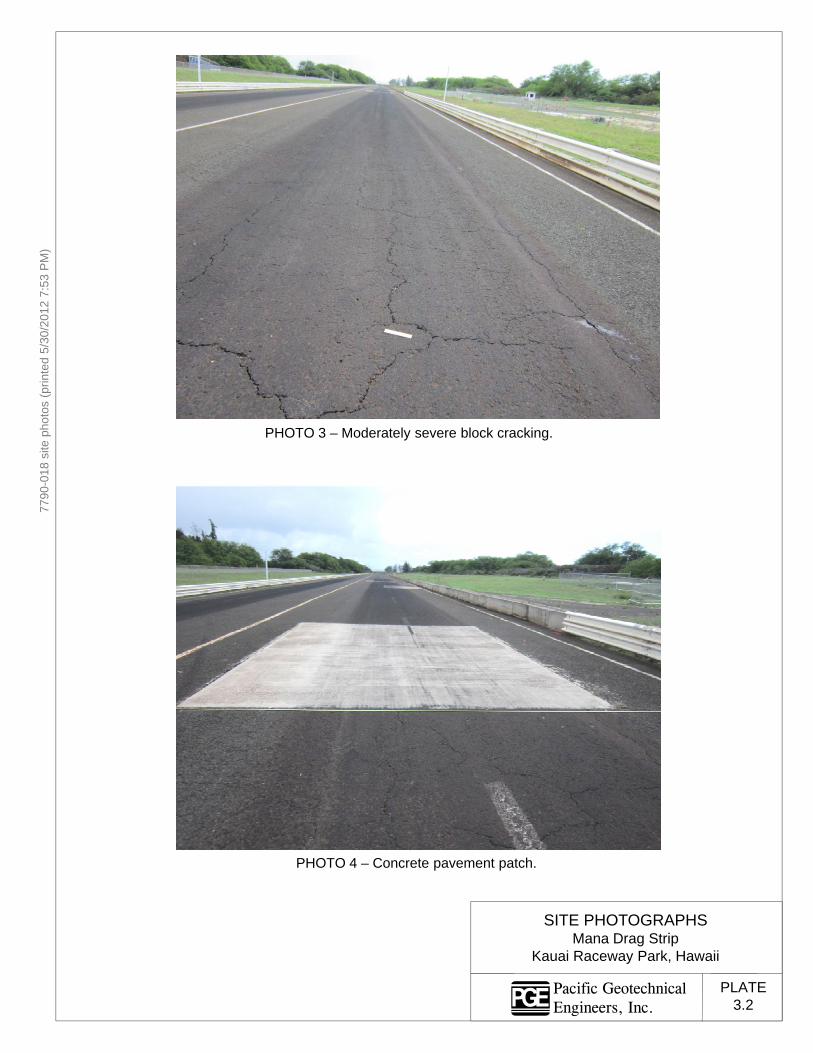
M)
(prin
ted
5/30
/201
2 7:
53 P
7790
-018
site
pho
tos
(
PHOTO 3 – Moderately severe block cracking.
SITE PHOTOGRAPHS
PHOTO 4 – Concrete pavement patch.
SITE PHOTOGRAPHSMana Drag Strip
Kauai Raceway Park, Hawaii
PLATE3.2
Pacific GeotechnicalEngineers, Inc.

M)
(prin
ted
5/30
/201
2 7:
53 P
7790
-018
site
pho
tos
(
PHOTO 5 – Highly to moderately severe block cracking.
SITE PHOTOGRAPHS
PHOTO 6 – High severity block cracking.
SITE PHOTOGRAPHSMana Drag Strip
Kauai Raceway Park, Hawaii
PLATE3.3
Pacific GeotechnicalEngineers, Inc.

M)
(prin
ted
5/30
/201
2 7:
53 P
7790
-018
site
pho
tos
(
PHOTO 7 – Finish line at quarter mile.
SITE PHOTOGRAPHS
PHOTO 8 – Grass in cracks.
SITE PHOTOGRAPHSMana Drag Strip
Kauai Raceway Park, Hawaii
PLATE3.4
Pacific GeotechnicalEngineers, Inc.

M)
(prin
ted
5/30
/201
2 7:
53 P
7790
-018
site
pho
tos
(
PHOTO 9 – Raveling and loss of aggregate.
SITE PHOTOGRAPHS
PHOTO 10 – Pavement crack at paving joint.
SITE PHOTOGRAPHSMana Drag Strip
Kauai Raceway Park, Hawaii
PLATE3.5
Pacific GeotechnicalEngineers, Inc.

M)
(prin
ted
5/30
/201
2 7:
53 P
7790
-018
site
pho
tos
(
PHOTO 11 – Vegetation in cracks.
SITE PHOTOGRAPHS
PHOTO 12 – Near end of raceway, looking east.
SITE PHOTOGRAPHSMana Drag Strip
Kauai Raceway Park, Hawaii
PLATE3.6
Pacific GeotechnicalEngineers, Inc.

Mana Drag Strip – Rehabilitation of Pavement PGE Job No. 7790-018
Pacific GeotechnicalEngineers, Inc.
TABLE 1
SUMMARY OF EXISTING PAVEMENT SECTION
Location Assumed Station
Approximate Pavement Section (1)
(inch) Fat Clay (inch)
AC Coralline Gravel
C-1 0+-50 1-5/8 6-7/8 3 (2)
C-2 0+37 Concrete 4-1/2 2-1/2 6 (2)
C-3 3+75 2 4-1/2 8-1/2 (2)
C-4 7+50 2 5-1/2 3 (2)
C-5 11+22 2 5 6 (2)
C-6 15+00 1-7/8 5-1/8 6-1/2 (2)
C-7 18+75 1-1/2 5 6-1/2 (2)
C-8 22+50 1-7/8 6-1/8 5-1/2 (2)
C-9 26+25 1-3/8 6-5/8 5-1/2 (2)
C-10 29+93 1-1/2 5-3/4 5-1/2 (2)
C-11 33+75 2-1/2 6 6 (2)
B-1 6+05 2 6 10
B-2 10+32 1-7/8 6 7
B-3 13+00 3 6 9
B-4 21+00 1-7/8 6 6
B-5 29+00 2 7 7
Notes: (1) Pavement section estimated from core and borehole measurements.
(2) Fat clay thickness estimated based on DCP results.

Mana Drag Strip – Rehabilitation of Pavement PGE Job No. 7790-018
Pacific GeotechnicalEngineers, Inc.
REFERENCES
1. Macdonald, Gordon A., Stearns, H.T., Cox, D.C., and Davis, D.A., Geologic and Topographic Map of the Island of Kauai, Hawaii, United States Geological Survey, colored geologic map, 1960.
2. Sherrod, David R., Sinton, J.M., Watkins, S.E., and Brunt, K.M., Geologic Map of the
State of Hawaii: U.S. Geological Survey, Open-file Report 2007-1089, Version 1.0, Plate 2, geologic map of the island of Kauai, 2007.
3. AASHTO Guide for Design of Pavement Structures, American Association of State
Highway and Transportation Officials, 1993. 4. United States Department of Agriculture, Natural Resources Conservation Service, Web
Soil Survey, Island of Oahu, Hawaii (HI990), Soil Maps Version 1, February 28, 2008 and Soil Data Version 6, December 31, 2006.
5. AASHTOWare, DARWin, version 3.1, Pavement Design, Analysis & Rehabilitation for
Windows. 6. Kauai Raceway Park, New Concrete Starting Line Pads and Track Asphalt, Preliminary
Specifications, June 13, 2011.

Mana Drag Strip – Rehabilitation of Pavement PGE Job No. 7790-018
Pacific GeotechnicalEngineers, Inc.
APPENDIX A
FIELD EXPLORATION
The field exploration program for this project consisted of drilling five (5) soil test
borings to depths ranging from 6.1 to 10.5 feet below existing grades and performing sixteen
(16) pavement cores. The approximate locations of the borings and core samples are shown on
the Plot Plans, Plates 2.1 through 2.4 in the main text. The locations and elevations of the
borings and pavement cores were surveyed by Esaki Surveying and Mapping, Inc.
Prior to the start of field work, readily available underground utility plans were reviewed
to check for possible underground utility lines. The Hawaii One Call Center (HOCC) was
contacted to review the proposed boring, pavement cores, and bulk sample locations for possible
underground utility lines. AT&T HITS was also contacted to check the boring, pavement cores
and bulk sample locations for possible underground communication lines. As a final check, the
boring, pavement cores, and bulk sample locations were toned using a metal detector.
The borings were drilled by PGE’s subcontracted driller, Geolabs, Inc. using a Mobile
B-55G truck mounted drill rig with 4-inch diameter continuous flight augers. The pavement
cores were excavated by PGE’s subcontractor, Cushnie Construction Company, Inc., using a
coring machine. The drilling and coring was conducted under the technical observation of
PGE’s engineering personnel who maintained a log of the materials encountered in each boring
and core location, and obtained relatively undisturbed and disturbed soil samples for further
examination and laboratory testing.
Relatively undisturbed and disturbed soil samples were obtained in the borings using a
stainless steel split barrel sampler with an outside diameter (O.D.) of 3.3 inches and an inside
diameter (I.D.) of 2.4 inches and a Standard Penetration Test (SPT) split spoon sampler with an
O.D. and I.D. of 2 and 1.4 inches, respectively. The sampler was driven with blows from a
140 pounds hammer falling 30 inches. Each sampling attempt consisted of driving the sampler
for a total distance of approximately 18 inches, and recording the blow counts for each 6 inches
of penetration. The blow counts for the last 12 inches of penetration were recorded. The blow
counts for the 3.3 inches diameter split barrel sampler represent actual blow count and have not
been corrected to equivalent SPT-N values.

Mana Drag Strip – Rehabilitation of Pavement PGE Job No. 7790-018
Pacific GeotechnicalEngineers, Inc.
After the completion of the field work, the soil samples retrieved from the borings,
pavement cores, and bulk samples were shipped to PGE’s laboratory on Oahu for further
examination and testing.
Graphical representations of the soils encountered in the borings are presented on the
Log of Borings, Plates A-1.1 through A-1.5. The soils encountered in the boring were initially
classified in the field in general accordance with ASTM D 2488 test procedures and the Unified
Soil Classification System presented on Plates A-2.1 and A-2.2. Additional field data from
PGE’s observations of the drilling process, soil cuttings, drilling rate, and soil sampling were
used to supplement the field classifications of the soils. The field classifications were later
refined according to ASTM D 2487 based on the results of laboratory tests performed on
selected soil samples.
Ground water was encountered in the borings at the time of drilling. The measured
water levels are indicated on the boring logs. Because of the proximity of the site to the ocean,
the groundwater level at the site is anticipated to fluctuate with the tides, seasonal variations,
and rainfall landward of the site.
The pavement at the boring and core locations was cored using a coring machine to
obtain cores of approximately 4 inches in diameter. Photographs of the pavement cores are
presented on Plates A-3.1 through A-3.16.
Eleven (11) DCP tests were performed below the pavement at select pavement coring
locations. The test consisted of driving a conical rod with blows from a 17.6 pounds drop
hammer falling 22.6 inches. The penetration resistance provides correlation of the soil CBR
values. The DCP test results are presented on Plates A-4.1 through A-4.11.
At the completion of drilling, the borings were backfilled with gravel and capped with
AC. The core holes were backfilled with gravel and capped with cold mix AC or concrete.
- o0o -
The following plates are attached and complete this appendix.
Plates A-1.1 through A-1.5 - Log of Borings, B-1 through B-5 Plates A-2.1 and A-2.2 - Unified Soil Classification System Plates A-3.1 through A-3.16 - Photograph of Pavement Cores Plates A-4.1 through A-4.11 - Dynamic Cone Penetrometer Test Data

2 inches of asphaltic concreteYellowish brown silty coralline gravel, medium dense, withcoralline sand, mosit (fill)Light reddish brown fat clay, very stiff, with coralline sand,moist (fill)Light yellowish brown poorly graded coralline sand, mediumdense, with silt, moist (beach/dune deposit)
grades weakly cemented and saturated(Water level at 1100 hours on 4/10/2012)
grades very dense
Boring completed at 10.5 feet on 4/10/2012.
61
52
22
26
42
66/5"
79
ACGMCHSP
40
6
6
18
81
97
107
Drilling Equipment Mobile B-55GDrilling Method 4-inch Augers, Rotary Wash
Logged By L. Oshiro
Date Ended 4/10/2012
Water Level (depth) 7.0 ft
Datum Mean Sea LevelDate Started 4/10/2012
Northing N/A
Easting N/A
± feetSurface Elevation +9.7
SURFACE
Description
Drawn By LML
Job No. 7790-018Project Mana Drag Strip, Rehabilitation of Pavement
Location Kekaha, KauaiBORING B-1 (Page 1 of 1)
BO
RE
HO
LE L
OG
TR
UE
SC
ALI
NG
- P
AC
IFIC
GE
OT
EC
HN
ICA
L F
INA
L D
AT
A T
EM
PLA
TE
.GD
T -
5/3
0/1
2 2
0:03
- J
:\77
90-0
18\E
NG
INE
ER
ING
\GIN
T\7
790
-018
B-L
OG
S_L
AB
.GP
J
LOG OF BORINGNotes: PLATE
A-1.1Disturbed sample
Cor
e T
ype
Dep
th (
ft)
Lab Data Core InfoR
ecov
ery
(%)
RQ
D (
%)
Sam
ples
Blo
ws/
ft
Soi
l Cla
ss
Gra
phic
Log
Moi
stur
eC
onte
nt (
%)
Dry
Den
sity
(pcf
)
Sample lost during extraction
3.3-inch O.D. split barrel sampler
DRIVING ENERGY: 140 lb dropping 30 inches
2-inch O.D. SPT (split-spoon sampler)
Core run Piston sample
4
8

1-7/8 inches of asphaltic concreteYellowish brown silty coralline gravel, medium dense, withcoralline sand, moist (fill)Light reddish brown fat clay, very stiff, with coralline sand,moist (fill)Light yellowish brown poorly graded coralline sand, mediumdense, with silt, moist (beach/dune deposit)
grades weakly cemented
(Water level at 1155 hours on 4/10/2012)grades very dense and saturated
Boring completed at 10.5 feet on 4/10/2012.
48
28
31
23
64/4"
65
ACGMCHSP
5
5
23
20
103
101
104
Drilling Equipment Mobile B-55GDrilling Method 4-inch Augers, Rotary Wash
Logged By L. Oshiro
Date Ended 4/10/2012
Water Level (depth) 7.2 ft
Datum Mean Sea LevelDate Started 4/10/2012
Northing N/A
Easting N/A
± feetSurface Elevation +9.6
SURFACE
Description
Drawn By LML
Job No. 7790-018Project Mana Drag Strip, Rehabilitation of Pavement
Location Kekaha, KauaiBORING B-2 (Page 1 of 1)
BO
RE
HO
LE L
OG
TR
UE
SC
ALI
NG
- P
AC
IFIC
GE
OT
EC
HN
ICA
L F
INA
L D
AT
A T
EM
PLA
TE
.GD
T -
5/3
0/1
2 2
0:04
- J
:\77
90-0
18\E
NG
INE
ER
ING
\GIN
T\7
790
-018
B-L
OG
S_L
AB
.GP
J
LOG OF BORINGNotes: PLATE
A-1.2Disturbed sample
Cor
e T
ype
Dep
th (
ft)
Lab Data Core InfoR
ecov
ery
(%)
RQ
D (
%)
Sam
ples
Blo
ws/
ft
Soi
l Cla
ss
Gra
phic
Log
Moi
stur
eC
onte
nt (
%)
Dry
Den
sity
(pcf
)
Sample lost during extraction
3.3-inch O.D. split barrel sampler
DRIVING ENERGY: 140 lb dropping 30 inches
2-inch O.D. SPT (split-spoon sampler)
Core run Piston sample
4
8

3 inches of asphaltic concreteYellowish brown silty coralline gravel, medium dense, withcoralline sand, moist (fill)Light reddish brown fat clay, very stiff, with coralline sand,moist (fill)Light yellowish brown poorly graded coralline sand, dense,with silt, moist (beach/dune deposit)
grades medium dense
grades dense and weakly cemented
grades very dense and saturated(Water level at 1239 hours on 4/10/2012)
Boring completed at 10.5 feet on 4/10/2012.
36
41
26
33
83
70
ACGMCHSP
38
15
23
88
Drilling Equipment Mobile B-55GDrilling Method 4-inch Augers, Rotary Wash
Logged By L. Oshiro
Date Ended 4/10/2012
Water Level (depth) 7.3 ft
Datum Mean Sea LevelDate Started 4/10/2012
Northing N/A
Easting N/A
± feetSurface Elevation +10.0
SURFACE
Description
Drawn By LML
Job No. 7790-018Project Mana Drag Strip, Rehabilitation of Pavement
Location Kekaha, KauaiBORING B-3 (Page 1 of 1)
BO
RE
HO
LE L
OG
TR
UE
SC
ALI
NG
- P
AC
IFIC
GE
OT
EC
HN
ICA
L F
INA
L D
AT
A T
EM
PLA
TE
.GD
T -
5/3
0/1
2 2
0:04
- J
:\77
90-0
18\E
NG
INE
ER
ING
\GIN
T\7
790
-018
B-L
OG
S_L
AB
.GP
J
LOG OF BORINGNotes: PLATE
A-1.3Disturbed sample
Cor
e T
ype
Dep
th (
ft)
Lab Data Core InfoR
ecov
ery
(%)
RQ
D (
%)
Sam
ples
Blo
ws/
ft
Soi
l Cla
ss
Gra
phic
Log
Moi
stur
eC
onte
nt (
%)
Dry
Den
sity
(pcf
)
Sample lost during extraction
3.3-inch O.D. split barrel sampler
DRIVING ENERGY: 140 lb dropping 30 inches
2-inch O.D. SPT (split-spoon sampler)
Core run Piston sample
4
8

1.8 inches of asphaltic concreteYellowish brown silty coralline gravel, medium dense, withcoralline sand, moist (fill)Light reddish brown fat clay, very stiff, with coralline sand,moist (fill)Light yellowish brown poorly graded coralline sand, dense,with silt, moist (beach/dune deposit)
grades medium dense
grades medium dense to denseBoring completed at 6.1 feet on 4/10/2012.
Ground water not encountered.
45
31
28
30
ACGMCHSP
43
7
72
94
Drilling Equipment Mobile B-55GDrilling Method 4-inch Augers, Rotary Wash
Logged By L. Oshiro
Date Ended 4/10/2012
Water Level (depth) N/A
Datum Mean Sea LevelDate Started 4/10/2012
Northing N/A
Easting N/A
± feetSurface Elevation +9.8
SURFACE
Description
Drawn By LML
Job No. 7790-018Project Mana Drag Strip, Rehabilitation of Pavement
Location Kekaha, KauaiBORING B-4 (Page 1 of 1)
BO
RE
HO
LE L
OG
TR
UE
SC
ALI
NG
- P
AC
IFIC
GE
OT
EC
HN
ICA
L F
INA
L D
AT
A T
EM
PLA
TE
.GD
T -
5/3
0/1
2 2
0:05
- J
:\77
90-0
18\E
NG
INE
ER
ING
\GIN
T\7
790
-018
B-L
OG
S_L
AB
.GP
J
LOG OF BORINGNotes: PLATE
A-1.4Disturbed sample
Cor
e T
ype
Dep
th (
ft)
Lab Data Core InfoR
ecov
ery
(%)
RQ
D (
%)
Sam
ples
Blo
ws/
ft
Soi
l Cla
ss
Gra
phic
Log
Moi
stur
eC
onte
nt (
%)
Dry
Den
sity
(pcf
)
Sample lost during extraction
3.3-inch O.D. split barrel sampler
DRIVING ENERGY: 140 lb dropping 30 inches
2-inch O.D. SPT (split-spoon sampler)
Core run Piston sample
4
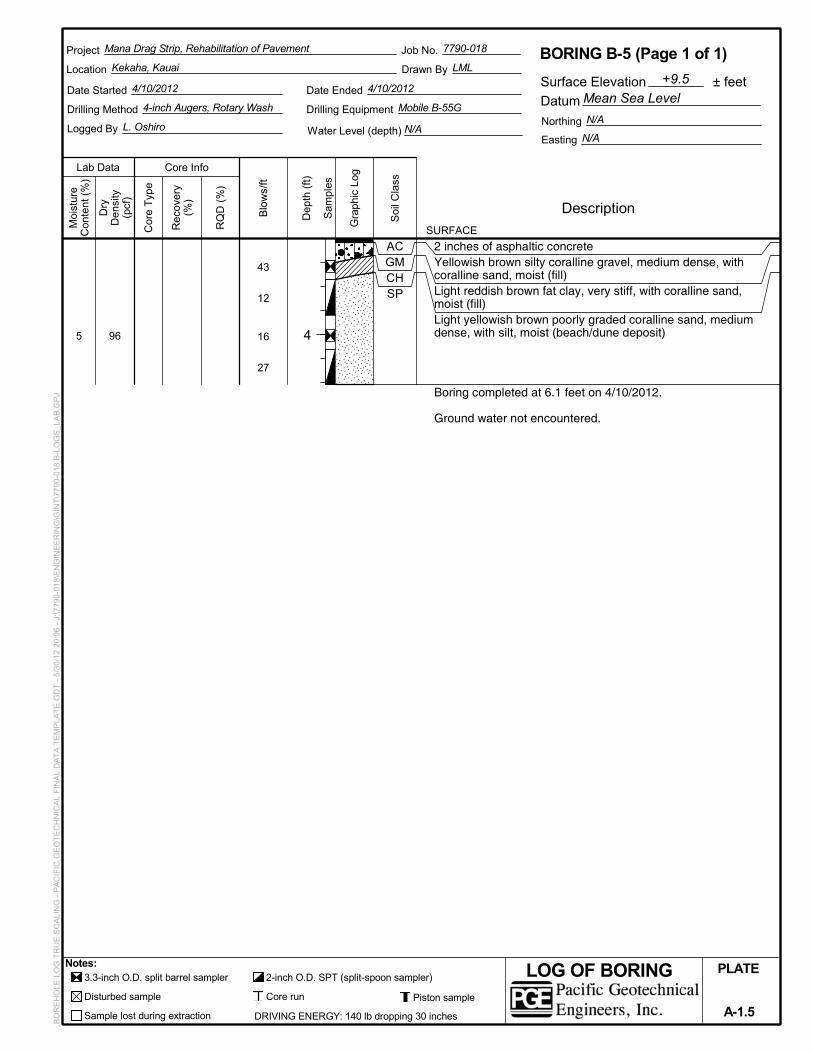
2 inches of asphaltic concreteYellowish brown silty coralline gravel, medium dense, withcoralline sand, moist (fill)Light reddish brown fat clay, very stiff, with coralline sand,moist (fill)Light yellowish brown poorly graded coralline sand, mediumdense, with silt, moist (beach/dune deposit)
Boring completed at 6.1 feet on 4/10/2012.
Ground water not encountered.
43
12
16
27
ACGMCHSP
5 96
Drilling Equipment Mobile B-55GDrilling Method 4-inch Augers, Rotary Wash
Logged By L. Oshiro
Date Ended 4/10/2012
Water Level (depth) N/A
Datum Mean Sea LevelDate Started 4/10/2012
Northing N/A
Easting N/A
± feetSurface Elevation +9.5
SURFACE
Description
Drawn By LML
Job No. 7790-018Project Mana Drag Strip, Rehabilitation of Pavement
Location Kekaha, KauaiBORING B-5 (Page 1 of 1)
BO
RE
HO
LE L
OG
TR
UE
SC
ALI
NG
- P
AC
IFIC
GE
OT
EC
HN
ICA
L F
INA
L D
AT
A T
EM
PLA
TE
.GD
T -
5/3
0/1
2 2
0:06
- J
:\77
90-0
18\E
NG
INE
ER
ING
\GIN
T\7
790
-018
B-L
OG
S_L
AB
.GP
J
LOG OF BORINGNotes: PLATE
A-1.5Disturbed sample
Cor
e T
ype
Dep
th (
ft)
Lab Data Core InfoR
ecov
ery
(%)
RQ
D (
%)
Sam
ples
Blo
ws/
ft
Soi
l Cla
ss
Gra
phic
Log
Moi
stur
eC
onte
nt (
%)
Dry
Den
sity
(pcf
)
Sample lost during extraction
3.3-inch O.D. split barrel sampler
DRIVING ENERGY: 140 lb dropping 30 inches
2-inch O.D. SPT (split-spoon sampler)
Core run Piston sample
4
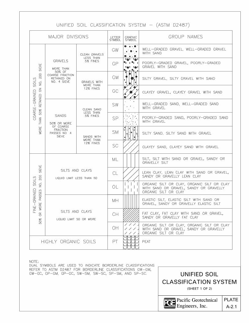
Pacific GeotechnicalEngineers, Inc.

Pacific GeotechnicalEngineers, Inc.

54 P
M)
tos
(prin
ted
5/30
/201
2 7:
577
90-0
18 a
c-co
re p
hot
PHOTOGRAPHS OF PAVEMENT CORES
C-1
PHOTOGRAPHS OF PAVEMENT CORESPavement Rehabilitation, Mana Drag Strip
Kekaha, Kauai, Hawaii
PLATE
A-3.1Pacific GeotechnicalEngineers, Inc.

54 P
M)
tos
(prin
ted
5/30
/201
2 7:
577
90-0
18 a
c-co
re p
hot
PHOTOGRAPHS OF PAVEMENT CORES
C-2
PHOTOGRAPHS OF PAVEMENT CORESPavement Rehabilitation, Mana Drag Strip
Kekaha, Kauai, Hawaii
PLATE
A-3.2Pacific GeotechnicalEngineers, Inc.
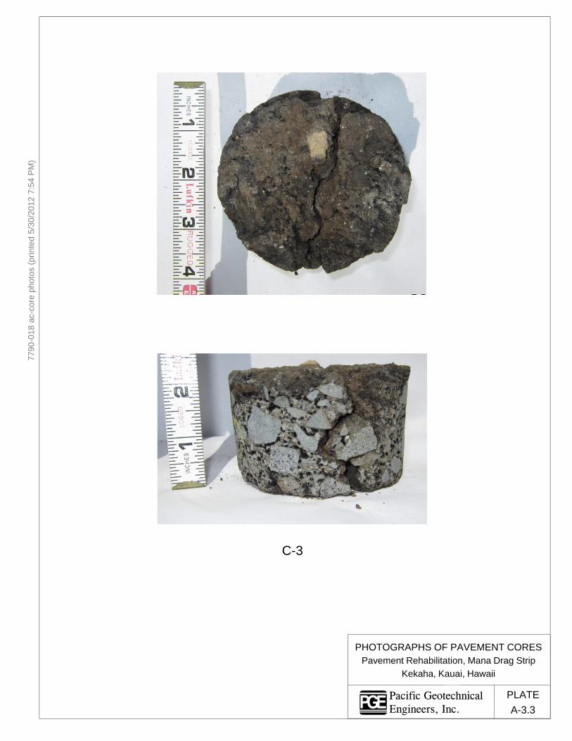
54 P
M)
tos
(prin
ted
5/30
/201
2 7:
577
90-0
18 a
c-co
re p
hot
C-3
PHOTOGRAPHS OF PAVEMENT CORESPHOTOGRAPHS OF PAVEMENT CORESPavement Rehabilitation, Mana Drag Strip
Kekaha, Kauai, Hawaii
PLATE
A-3.3Pacific GeotechnicalEngineers, Inc.

54 P
M)
tos
(prin
ted
5/30
/201
2 7:
577
90-0
18 a
c-co
re p
hot
PHOTOGRAPHS OF PAVEMENT CORES
C-4
PHOTOGRAPHS OF PAVEMENT CORESPavement Rehabilitation, Mana Drag Strip
Kekaha, Kauai, Hawaii
PLATE
A-3.4Pacific GeotechnicalEngineers, Inc.

54 P
M)
tos
(prin
ted
5/30
/201
2 7:
577
90-0
18 a
c-co
re p
hot
PHOTOGRAPHS OF PAVEMENT CORES
C-5
PHOTOGRAPHS OF PAVEMENT CORESPavement Rehabilitation, Mana Drag Strip
Kekaha, Kauai, Hawaii
PLATE
A-3.5Pacific GeotechnicalEngineers, Inc.

54 P
M)
tos
(prin
ted
5/30
/201
2 7:
577
90-0
18 a
c-co
re p
hot
PHOTOGRAPHS OF PAVEMENT CORES
C-6
PHOTOGRAPHS OF PAVEMENT CORESPavement Rehabilitation, Mana Drag Strip
Kekaha, Kauai, Hawaii
PLATE
A-3.6Pacific GeotechnicalEngineers, Inc.

54 P
M)
tos
(prin
ted
5/30
/201
2 7:
577
90-0
18 a
c-co
re p
hot
C-7
PHOTOGRAPHS OF PAVEMENT CORESPHOTOGRAPHS OF PAVEMENT CORESPavement Rehabilitation, Mana Drag Strip
Kekaha, Kauai, Hawaii
PLATE
A-3.7Pacific GeotechnicalEngineers, Inc.

54 P
M)
tos
(prin
ted
5/30
/201
2 7:
577
90-0
18 a
c-co
re p
hot
C-8
PHOTOGRAPHS OF PAVEMENT CORESPHOTOGRAPHS OF PAVEMENT CORESPavement Rehabilitation, Mana Drag Strip
Kekaha, Kauai, Hawaii
PLATE
A-3.8Pacific GeotechnicalEngineers, Inc.

54 P
M)
tos
(prin
ted
5/30
/201
2 7:
577
90-0
18 a
c-co
re p
hot
C-9
PHOTOGRAPHS OF PAVEMENT CORESPHOTOGRAPHS OF PAVEMENT CORESPavement Rehabilitation, Mana Drag Strip
Kekaha, Kauai, Hawaii
PLATE
A-3.9Pacific GeotechnicalEngineers, Inc.

54 P
M)
tos
(prin
ted
5/30
/201
2 7:
577
90-0
18 a
c-co
re p
hot
C-10
PHOTOGRAPHS OF PAVEMENT CORESPHOTOGRAPHS OF PAVEMENT CORESPavement Rehabilitation, Mana Drag Strip
Kekaha, Kauai, Hawaii
PLATE
A-3.10Pacific GeotechnicalEngineers, Inc.

54 P
M)
tos
(prin
ted
5/30
/201
2 7:
577
90-0
18 a
c-co
re p
hot
PHOTOGRAPHS OF PAVEMENT CORES
C-11
PHOTOGRAPHS OF PAVEMENT CORESPavement Rehabilitation, Mana Drag Strip
Kekaha, Kauai, Hawaii
PLATE
A-3.11Pacific GeotechnicalEngineers, Inc.

54 P
M)
tos
(prin
ted
5/30
/201
2 7:
577
90-0
18 a
c-co
re p
hot
B 1B-1
PHOTOGRAPHS OF PAVEMENT CORESPHOTOGRAPHS OF PAVEMENT CORESPavement Rehabilitation, Mana Drag Strip
Kekaha, Kauai, Hawaii
PLATE
A-3.12Pacific GeotechnicalEngineers, Inc.

54 P
M)
tos
(prin
ted
5/30
/201
2 7:
577
90-0
18 a
c-co
re p
hot
PHOTOGRAPHS OF PAVEMENT CORES
B-2
PHOTOGRAPHS OF PAVEMENT CORESPavement Rehabilitation, Mana Drag Strip
Kekaha, Kauai, Hawaii
PLATE
A-3.13Pacific GeotechnicalEngineers, Inc.

54 P
M)
tos
(prin
ted
5/30
/201
2 7:
577
90-0
18 a
c-co
re p
hot
PHOTOGRAPHS OF PAVEMENT CORES
B-3
PHOTOGRAPHS OF PAVEMENT CORESPavement Rehabilitation, Mana Drag Strip
Kekaha, Kauai, Hawaii
PLATE
A-3.14Pacific GeotechnicalEngineers, Inc.

54 P
M)
tos
(prin
ted
5/30
/201
2 7:
577
90-0
18 a
c-co
re p
hot
PHOTOGRAPHS OF PAVEMENT CORES
B-4
PHOTOGRAPHS OF PAVEMENT CORESPavement Rehabilitation, Mana Drag Strip
Kekaha, Kauai, Hawaii
PLATE
A-3.15Pacific GeotechnicalEngineers, Inc.

54 P
M)
tos
(prin
ted
5/30
/201
2 7:
577
90-0
18 a
c-co
re p
hot
PHOTOGRAPHS OF PAVEMENT CORES
B-5
PHOTOGRAPHS OF PAVEMENT CORESPavement Rehabilitation, Mana Drag Strip
Kekaha, Kauai, Hawaii
PLATE
A-3.16Pacific GeotechnicalEngineers, Inc.

J:\7
790-
018\
Fie
ld D
ata\
7790
-018
dcp
c-1
.xls
m (
5/30
/201
2)
0 5 10 15 20
010
2030
4050
6070
8090
100
round Surface (inches)
CBR value
Correlated
CBR
value
sC‐1
0 5 10 15 20
0.0
0.5
1.0
1.5
2.0
2.5
round Surface (inches)Pe
netration pe
r Blow
(inche
s)
DCP
Test D
ata
C‐1
100+
25 30 35 40
Depth Below Gr
20 25 30 35
Depth Below Gr
Dyn
am
ic C
on
e P
en
etr
om
ete
r T
est
Da
taR
ehab
ilita
tion
of P
avem
ent,
Man
a D
rag
Str
ip
Kek
aha,
Kau
ai,
Haw
aii
PLATE
A-4.1
Note: CBR
value
sgreater than
100
are not sho
wn on
plot
100+

J:\7
790-
018\
Fie
ld D
ata\
7790
-018
dcp
c-2
.xls
m (
5/30
/201
2)
0 5 10 15 20 25
010
2030
4050
6070
8090
100
round Surface (inches)
CBR value
Correlated
CBR
value
sC‐2
0 5 10 15 20 25
0.0
0.5
1.0
1.5
ound Surface (inches)Pe
netration pe
r Blow
(inche
s)
DCP
Test D
ata
C‐2
30 35 40 45
Depth Below Gr
25 30 35 40 45
Depth Below Gro
Dyn
am
ic C
on
e P
en
etr
om
ete
r T
est
Da
taRe
habilitation of Pavem
ent, M
ana Drag Strip
Kekaha, Kauai, H
awaii
PLATE
A-4.2

J:\7
790-
018\
Fie
ld D
ata\
7790
-018
dcp
c-3
.xls
m (
5/30
/201
2)
0 5 10 15 20
010
2030
4050
6070
8090
100
round Surface (inches)
CBR value
Correlated
CBR
value
sC‐3
0 5 10 15 20
0.0
0.4
0.8
1.2
1.6
ound Surface (inches)Pe
netration pe
r Blow
(inche
s)
DCP
Test D
ata
C‐3
100+
100+
25 30 35 40
Depth Below Gr
25 30 35 40
Depth Below Gro
Dyn
am
ic C
on
e P
en
etr
om
ete
r T
est
Da
taRe
habilitation of Pavem
ent, M
ana Drag Strip
Kekaha, Kauai, H
awaii
PLATE
A-4.3
Note: CBR
value
sgreater than
100
are not sho
wn on
plot
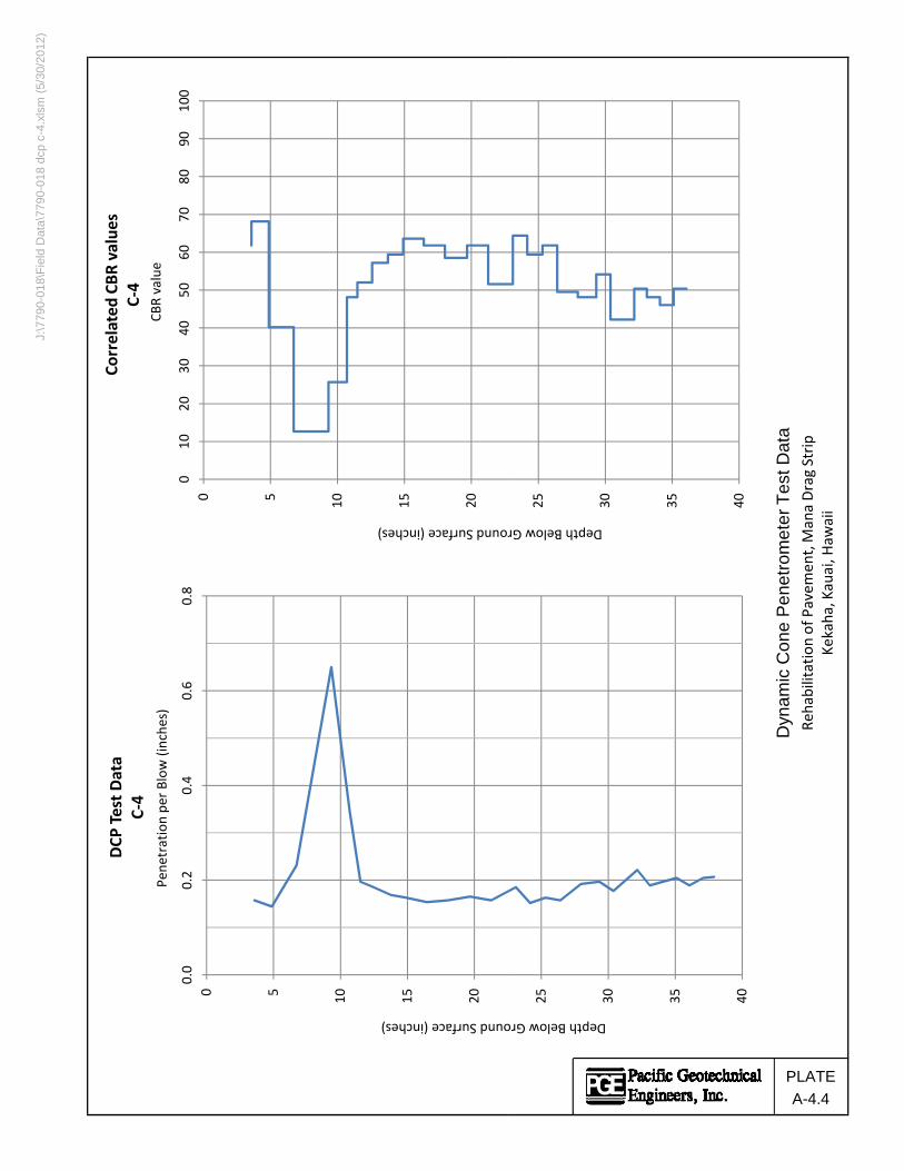
J:\7
790-
018\
Fie
ld D
ata\
7790
-018
dcp
c-4
.xls
m (
5/30
/201
2)
0 5 10 15 20
010
2030
4050
6070
8090
100
round Surface (inches)
CBR value
Correlated
CBR
value
sC‐4
0 5 10 15 20
0.0
0.2
0.4
0.6
0.8
ound Surface (inches)Pe
netration pe
r Blow
(inche
s)
DCP
Test D
ata
C‐4
25 30 35 40
Depth Below Gr
25 30 35 40
Depth Below Gro
Dyn
am
ic C
on
e P
en
etr
om
ete
r T
est
Da
taRe
habilitation of Pavem
ent, M
ana Drag Strip
Kekaha, Kauai, H
awaii
PLATE
A-4.4

J:\7
790-
018\
Fie
ld D
ata\
7790
-018
dcp
c-5
.xls
m (
5/30
/201
2)
0 5 10 15 20
010
2030
4050
6070
8090
100
round Surface (inches)
CBR value
Correlated
CBR
value
sC‐5
0 5 10 15 20
0.0
0.4
0.8
1.2
ound Surface (inches)Pe
netration pe
r Blow
(inche
s)
DCP
Test D
ata
C‐5
25 30 35 40
Depth Below Gr
25 30 35 40
Depth Below Gro
Dyn
am
ic C
on
e P
en
etr
om
ete
r T
est
Da
taRe
habilitation of Pavem
ent, M
ana Drag Strip
Kekaha, Kauai, H
awaii
PLATE
A-4.5

J:\7
790-
018\
Fie
ld D
ata\
7790
-018
dcp
c-6
.xls
m (
5/30
/201
2)
0 5 10 15 20
010
2030
4050
6070
8090
100
round Surface (inches)
CBR value
Correlated
CBR
value
sC‐6
0 5 10 15 20
0.0
0.2
0.4
0.6
0.8
1.0
ound Surface (inches)Pe
netration pe
r Blow
(inche
s)
DCP
Test D
ata
C‐6
100+
25 30 35 40
Depth Below Gr
25 30 35 40
Depth Below Gro
Dyn
am
ic C
on
e P
en
etr
om
ete
r T
est
Da
taRe
habilitation of Pavem
ent, M
ana Drag Strip
Kekaha, Kauai, H
awaii
PLATE
A-4.6
Note: CBR
value
sgreater than
100
are not sho
wn on
plot

J:\7
790-
018\
Fie
ld D
ata\
7790
-018
dcp
c-7
.xls
m (
5/30
/201
2)
0 5 10 15 20
010
2030
4050
6070
8090
100
round Surface (inches)
CBR value
Correlated
CBR
value
sC‐7
0 5 10 15 20
0.0
0.5
1.0
1.5
2.0
ound Surface (inches)Pe
netration pe
r Blow
(inche
s)
DCP
Test D
ata
C‐7
25 30 35 40
Depth Below Gr
25 30 35 40
Depth Below Gro
Dyn
am
ic C
on
e P
en
etr
om
ete
r T
est
Da
taRe
habilitation of Pavem
ent, M
ana Drag Strip
Kekaha, Kauai, H
awaii
PLATE
A-4.7

J:\7
790-
018\
Fie
ld D
ata\
7790
-018
dcp
c-8
.xls
m (
5/30
/201
2)
0 5 10 15 20
010
2030
4050
6070
8090
100
round Surface (inches)
CBR value
Correlated
CBR
value
sC‐8
0 5 10 15 20
0.0
0.5
1.0
1.5
ound Surface (inches)Pe
netration pe
r Blow
(inche
s)
DCP
Test D
ata
C‐8
25 30 35 40
Depth Below Gr
25 30 35 40
Depth Below Gro
Dyn
am
ic C
on
e P
en
etr
om
ete
r T
est
Da
taRe
habilitation of Pavem
ent, M
ana Drag Strip
Kekaha, Kauai, H
awaii
PLATE
A-4.8

J:\7
790-
018\
Fie
ld D
ata\
7790
-018
dcp
c-9
.xls
m (
5/30
/201
2)
0 5 10 15 20
010
2030
4050
6070
8090
100
round Surface (inches)
CBR value
Correlated
CBR
value
sC‐9
0 5 10 15 20
0.0
0.2
0.4
0.6
0.8
ound Surface (inches)Pe
netration pe
r Blow
(inche
s)
DCP
Test D
ata
C‐9
100+
25 30 35 40
Depth Below Gr
25 30 35 40
Depth Below Gro
Dyn
am
ic C
on
e P
en
etr
om
ete
r T
est
Da
taRe
habilitation of Pavem
ent, M
ana Drag Strip
Kekaha, Kauai, H
awaii
PLATE
A-4.9
Note: CBR
value
sgreater than
100
are not sho
wn on
plot

J:\7
790-
018\
Fie
ld D
ata\
7790
-018
dcp
c-1
0.xl
sm (
5/30
/201
2)
0 5 10 15 20
010
2030
4050
6070
8090
100
round Surface (inches)
CBR value
Correlated
CBR
value
sC‐10
0 5 10 15 20
0.0
0.2
0.4
0.6
ound Surface (inches)Pe
netration pe
r Blow
(inche
s)
DCP
Test D
ata
C‐10
20 25 30 35
Depth Below Gr
20 25 30 35
Depth Below Gro
Dyn
am
ic C
on
e P
en
etr
om
ete
r T
est
Da
taRe
habilitation of Pavem
ent, M
ana Drag Strip
Kekaha, Kauai, H
awaii
PLATE
A-4.10

J:\7
790-
018\
Fie
ld D
ata\
7790
-018
dcp
c-1
1.xl
sm (
5/30
/201
2)
0 5 10 15 20
010
2030
4050
6070
8090
100
round Surface (inches)
CBR value
Correlated
CBR
value
sC‐11
0 5 10 15 20
0.0
0.2
0.4
0.6
0.8
1.0
1.2
ound Surface (inches)Pe
netration pe
r Blow
(inche
s)
DCP
Test D
ata
C‐11
100+
25 30 35 40
Depth Below Gr
25 30 35 40
Depth Below Gro
Dyn
am
ic C
on
e P
en
etr
om
ete
r T
est
Da
taRe
habilitation of Pavem
ent, M
ana Drag Strip
Kekaha, Kauai, H
awaii
PLATE
A-4.11
Note: CBR
value
sgreater than
100
are not sho
wn on
plot

Mana Drag Strip – Rehabilitation of Pavement PGE Job No. 7790-018
Pacific GeotechnicalEngineers, Inc.
APPENDIX B
LABORATORY TESTING
GENERAL - To evaluate their engineering properties, selected soil samples obtained during the
field exploration were subjected to laboratory moisture content and dry density determinations,
Atterberg Limits, gradation analysis, moisture-density relations tests, laboratory single point
CBR tests, strength tests, and R-value tests. The tests and their results are described in the
following paragraphs.
MOISTURE CONTENT AND DRY DENSITY - Relatively undisturbed selected soil samples
were tested to measure their in-situ moisture contents and dry densities. The tests were
performed in general accordance with ASTM D 2216 test method. Results of the moisture
content and dry density determinations are presented on the Logs of Borings, Plates A-1.1
through A-1.5 at the respective sample depths.
ATTERBERG LIMITS - Three (3) Atterberg Limits tests were performed on select samples in
general accordance with ASTM D 4318 test method. The test results are presented on Plate
B-1.
GRADATION ANALYSIS - Four (4) gradation analysis tests were performed in general
accordance with ASTM D 422 to evaluate grain size distribution. The test results are presented
on Plates B-2.1 and B-2.2.
MOISTURE-DENSITY RELATIONS - Two (2) moisture-density relations tests were
performed on bulk samples of near surface soils in general accordance with ASTM D 1557 test
method. The test results are presented on Plates B-3.1 and B-3.2.
CALIFORNIA BEARING RATIO (CBR) - Two (2) single point laboratory CBR tests were
performed on the bulk samples used in the moisture-density relations tests in general accordance
with ASTM D 1883 test method. The results of the CBR tests are presented on Plates B-4.1 and
B-4.2.

Mana Drag Strip – Rehabilitation of Pavement PGE Job No. 7790-018
Pacific GeotechnicalEngineers, Inc.
SHEAR STRENGTH - Two (2) shear strength tests were performed on relatively undisturbed
soil samples to evaluate their shear strength properties. The triaxial tests were performed under
unconsolidated, undrained (TX/UU) conditions in general accordance with ASTM D 2850 test
method. The tests were performed on soil samples at their field moisture contents. Total stress
properties were measured in these tests. The results of the strength tests are summarized in
Table B-1.
R-VALUE – R-value tests were performed on the bulk samples to measure their strength for
potential use in road pavements. The tests were performed in general accordance with
ASTM D 2844 test method by PGE’s subcontracted testing laboratory, Advanced Terra Testing,
Inc. (ATT). The test results are presented in Table B-2.
- o0o -
The following plates and tables are attached and complete this appendix.
Plate B-1 - Atterberg Limits Plates B-2.1 and B-2.2 - Gradation Curves Plates B-3.1 and B-3.2 - Laboratory Compaction Test Data
Plates B-4.1 and B-4.2 - Laboratory California Bearing Ratio (CBR) Test Results
Table B-1 - Shear Strength Test Results Table B-2 - R-Value Test Results

0
10
20
30
40
50
60
70
80
90
100
110
120
130
0 20 40 60 80 100 120 140 160 180
CL-ML
CL or OL
ML or OL
MH or OH
CH or OHA-LINE
ATTERBERG LIMITSKEY LOCATION SAMPLE DEPTH (ft) LIQUID LIMIT PLASTICITY INDEX
84
98
86
42
54
51
PLA
ST
ICIT
Y IN
DE
X
LIQUID LIMITS
B-1
B-5
Bulk 1
0.7
0.9
0.5 - 1.0
PACIFIC GEOTECHNICAL - ATTERBERG LIMITS - PACIFIC GEOTECHNICAL FINAL DATA TEMPLATE.GDT - 5/30/12 20:08 - J:\7790-018\ENGINEERING\GINT\7790-018 B-LOGS_LAB.GPJ
JOB NUMBER 7790-018
DATE 5/30/2012
PROJECT Mana Drag Strip, Rehabilitation of Pavement
LOCATION Kekaha, Kauai
PLA
TE
B-1
DRAWN BY LML

0
10
20
30
40
50
60
70
80
90
100
0.0010.010.1110100
200HYDROMETERU.S. STANDARD SIEVE SIZES
COBBLESGRAVEL SAND
SILT OR CLAYfine coarse
2.3
7.6
3.5
SP-SM
SP
SP
Light yellowish brown poorly graded coralline sandwith silt
Light yellowish brown poorly graded coralline sandwith silt
Light yellowish brown poorly graded coralline sandwith silt
PE
RC
EN
T F
INE
R B
Y W
EIG
HT
6 4 3 2 1.5U.S. STANDARD SIEVE OPENING IN INCHES
3/4
SYMBOL
40 50
LOCATION
30
6
23
7
1
coarse
GRADATION CURVE
CLASSIFICATION NAT. WC LL PL PI
20
DEPTH (ft)
60 100
GRAIN SIZE IN MILLIMETERS
6
medium fine
1/2 3/8 3 4 8 10 14 16 140
B-1
B-2
B-4
JOB NUMBER 7790-018
DATE 5/30/2012
PROJECT Mana Drag Strip, Rehabilitation of Pavement
LOCATION Kekaha, Kauai
PLA
TE
B-2.1
DRAWN BY LML
PACIFIC GEOTECHNICAL - GRAIN SIZE - PACIFIC GEOTECHNICAL FINAL DATA TEMPLATE.GDT - 5/30/12 20:10 - J:\7790-018\ENGINEERING\GINT\7790-018 B-LOGS_LAB.GPJ

0
10
20
30
40
50
60
70
80
90
100
0.0010.010.1110100
200HYDROMETERU.S. STANDARD SIEVE SIZES
COBBLESGRAVEL SAND
SILT OR CLAYfine coarse
1.0 - 2.0 SPYellowish brown poorly graded sand
PE
RC
EN
T F
INE
R B
Y W
EIG
HT
6 4 3 2 1.5U.S. STANDARD SIEVE OPENING IN INCHES
3/4
SYMBOL
40 50
LOCATION
30
2
1
coarse
GRADATION CURVE
CLASSIFICATION NAT. WC LL PL PI
20
DEPTH (ft)
60 100
GRAIN SIZE IN MILLIMETERS
6
medium fine
1/2 3/8 3 4 8 10 14 16 140
Bulk 2(Sta. 12+00)
JOB NUMBER 7790-018
DATE 5/30/2012
PROJECT Mana Drag Strip, Rehabilitation of Pavement
LOCATION Kekaha, Kauai
PLA
TE
B-2.2
DRAWN BY LML
PACIFIC GEOTECHNICAL - GRAIN SIZE - PACIFIC GEOTECHNICAL FINAL DATA TEMPLATE.GDT - 5/30/12 20:10 - J:\7790-018\ENGINEERING\GINT\7790-018 B-LOGS_LAB.GPJ

80
90
100
110
120
130
14010 15 20 25 30 35
PLATE B-3.1
Maximum Dry Unit Weight 104.8 pcf
Reddish brown fat clay (CH)Elevation +9.5 ft ± Mana Drag Strip, Rehabilitation of
Pavement
Kekaha, Kauai
Sample Location:
Bulk 1Station 6+00
Compaction Method ASTM D 1557
assu
med
spe
cific
gra
vity
ZERO AIRVOIDS
COMPACTION TEST DATA
MOISTURE CONTENT % OF DRY WEIGHT
Job Number:
Description of Material
7790-018
DR
Y U
NIT
WE
IGH
T IN
pcf
Project:
Sample Depth 0.5 - 1.0 ft
Optimum Moisture Content 25.0%
3.0
PA
CIF
IC G
EO
TE
CH
NIC
AL
- C
OM
PA
CT
ION
- P
AC
IFIC
GE
OT
EC
HN
ICA
L F
INA
L D
AT
A T
EM
PLA
TE
.GD
T -
5/3
0/12
20:
12
- J:
\779
0-0
18\E
NG
INE
ER
ING
\GIN
T\7
790
-018
B-L
OG
S_L
AB
.GP
J

80
90
100
110
120
130
1400 5 10 15 20 25
PLATE B-3.2
Maximum Dry Unit Weight 107.7 pcf
Yellowish brown poorly graded sand
(SP)
Elevation +9.0 ft ± Mana Drag Strip, Rehabilitation of
Pavement
Kekaha, Kauai
Sample Location:
Bulk 2Station 12+00
Compaction Method ASTM D 1557
assu
med
spe
cific
gra
vity
ZERO AIRVOIDS
COMPACTION TEST DATA
MOISTURE CONTENT % OF DRY WEIGHT
Job Number:
Description of Material
7790-018
DR
Y U
NIT
WE
IGH
T IN
pcf
Project:
Sample Depth 1.0 - 2.0 ft
Optimum Moisture Content 12.5%
2.4
PA
CIF
IC G
EO
TE
CH
NIC
AL
- C
OM
PA
CT
ION
- P
AC
IFIC
GE
OT
EC
HN
ICA
L F
INA
L D
AT
A T
EM
PLA
TE
.GD
T -
5/3
0/12
20:
12
- J:
\779
0-0
18\E
NG
INE
ER
ING
\GIN
T\7
790
-018
B-L
OG
S_L
AB
.GP
J

0
20
40
60
80
100
120
140
160
0 0.1 0.2 0.3 0.4 0.5 0.6
0.5 - 1.0
UN
IT L
OA
D O
N P
IST
ON
(ps
i)
6.6
Soil Description:
@ 0.1" @ 0.2"
Reddish brown fat clay (CH)
93.7
Test Method: ASTM D 1883
Depth(ft) Moisture
Content (%)
Before Soaking
3
Dry UnitWeight (pcf)
MoistureContent (%)
After Soaking
Dry UnitWeight (pcf) % Swell
LaboratoryCBR Value
24 35 3
LABORATORY CALIFORNIA BEARING RATIO (CBR) TEST RESULTSPENETRATION (inches)
87.9
Location
Bulk 1(Sta. 6+00)
JOB
NU
MB
ER
7790
-01
8
DA
TE
5/30
/201
2
PR
OJE
CT
Man
a D
rag
Str
ip, R
ehab
ilita
tion
of P
avem
ent
LOC
AT
ION
Kek
aha,
Kau
ai
PLATE B-4.1
DR
AW
N B
Y
L
ML
PA
CIF
IC G
EO
TE
CH
NIC
AL
- C
BR
PE
NE
TR
AT
ION
- P
AC
IFIC
GE
OT
EC
HN
ICA
L F
INA
L D
AT
A T
EM
PLA
TE
.GD
T -
5/3
0/1
2 2
0:14
- J
:\77
90-0
18\E
NG
INE
ER
ING
\GIN
T\7
790
-018
B-L
OG
S_L
AB
.GP
J

0
100
200
300
400
500
600
700
800
0 0.1 0.2 0.3 0.4 0.5 0.6
1.0 - 2.0
UN
IT L
OA
D O
N P
IST
ON
(ps
i)
0.0
Soil Description:
@ 0.1" @ 0.2"
Yellowish brown poorly graded sand (SP)
102.7
Test Method: ASTM D 1883
Depth(ft) Moisture
Content (%)
Before Soaking
22
Dry UnitWeight (pcf)
MoistureContent (%)
After Soaking
Dry UnitWeight (pcf) % Swell
LaboratoryCBR Value
10 20 26
LABORATORY CALIFORNIA BEARING RATIO (CBR) TEST RESULTSPENETRATION (inches)
102.7
Location
Bulk 2(Sta. 12+00)
JOB
NU
MB
ER
7790
-01
8
DA
TE
5/30
/201
2
PR
OJE
CT
Man
a D
rag
Str
ip, R
ehab
ilita
tion
of P
avem
ent
LOC
AT
ION
Kek
aha,
Kau
ai
PLATE B-4.2
DR
AW
N B
Y
L
ML
PA
CIF
IC G
EO
TE
CH
NIC
AL
- C
BR
PE
NE
TR
AT
ION
- P
AC
IFIC
GE
OT
EC
HN
ICA
L F
INA
L D
AT
A T
EM
PLA
TE
.GD
T -
5/3
0/1
2 2
0:14
- J
:\77
90-0
18\E
NG
INE
ER
ING
\GIN
T\7
790
-018
B-L
OG
S_L
AB
.GP
J
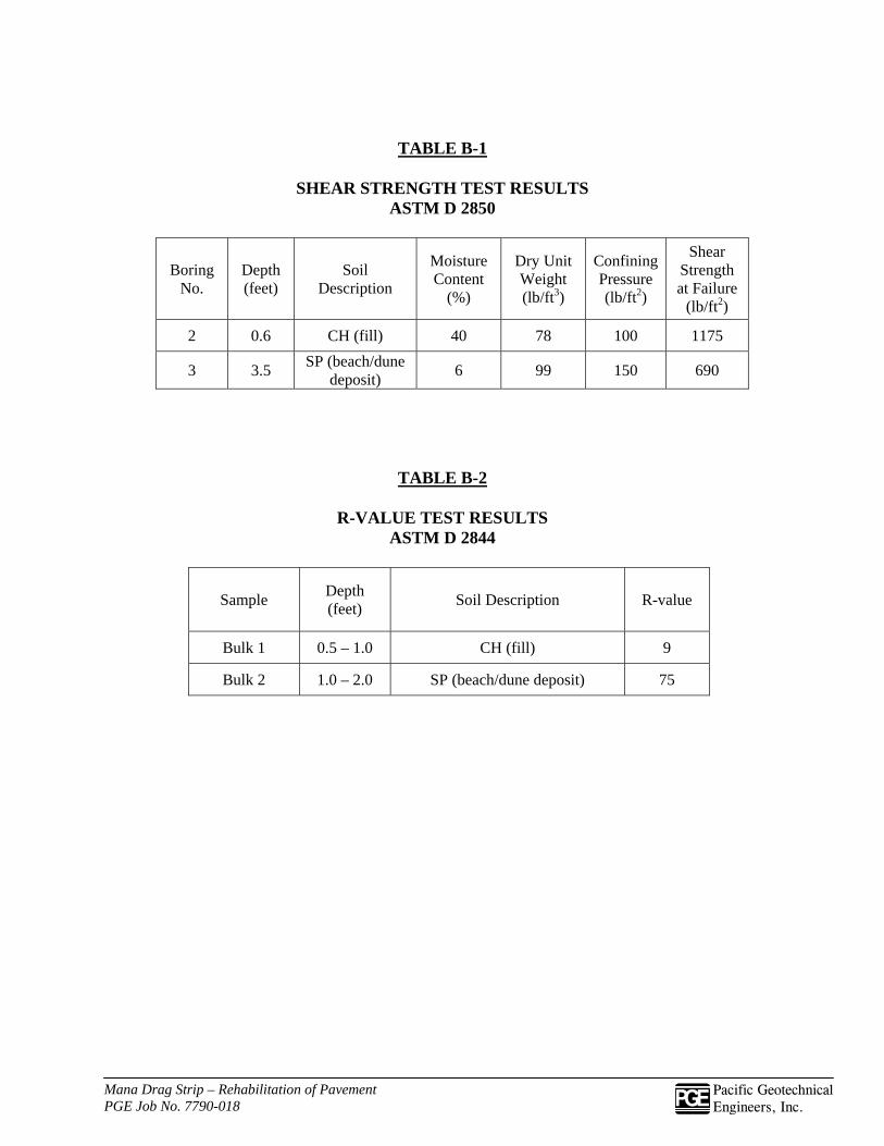
Mana Drag Strip – Rehabilitation of Pavement PGE Job No. 7790-018
Pacific GeotechnicalEngineers, Inc.
TABLE B-1
SHEAR STRENGTH TEST RESULTS ASTM D 2850
Boring No.
Depth (feet)
Soil Description
Moisture Content
(%)
Dry Unit Weight (lb/ft3)
Confining Pressure (lb/ft2)
Shear Strength at Failure
(lb/ft2)
2 0.6 CH (fill) 40 78 100 1175
3 3.5 SP (beach/dune
deposit) 6 99 150 690
TABLE B-2
R-VALUE TEST RESULTS ASTM D 2844
Sample Depth (feet)
Soil Description R-value
Bulk 1 0.5 – 1.0 CH (fill) 9
Bulk 2 1.0 – 2.0 SP (beach/dune deposit) 75