Embed Size (px)
Citation preview
Adaptive optics with pupil tracking forhigh resolution retinal imaging
Betul Sahin,1,∗ Barbara Lamory,2 Xavier Levecq,2 Fabrice Harms,2and Chris Dainty1
1Applied Optics, National University of Ireland, Galway, Ireland2Imagine Eyes, 18 Rue Charles de Gaulle, 91400, Orsay, France
Abstract: Adaptive optics, when integrated into retinal imaging systems,compensates for rapidly changing ocular aberrations in real time and resultsin improved high resolution images that reveal the photoreceptor mosaic.Imaging the retina at high resolution has numerous potential medicalapplications, and yet for the development of commercial products that canbe used in the clinic, the complexity and high cost of the present researchsystems have to be addressed. We present a new method to control thedeformable mirror in real time based on pupil tracking measurementswhich uses the default camera for the alignment of the eye in the retinalimaging system and requires no extra cost or hardware. We also present thefirst experiments done with a compact adaptive optics flood illuminationfundus camera where it was possible to compensate for the higher orderaberrations of a moving model eye and in vivo in real time based on pupiltracking measurements, without the real time contribution of a wavefrontsensor. As an outcome of this research, we showed that pupil tracking canbe effectively used as a low cost and practical adaptive optics tool for highresolution retinal imaging because eye movements constitute an importantpart of the ocular wavefront dynamics.
© 2012 Optical Society of AmericaOCIS codes: (110.1080) Active or adaptive optics; (100.4999) Pattern recognition, target track-ing; (170.4460) Ophthalmic optics and devices; (170.3890) Medical optics instrumentation.
References and links1. H. Hofer, N. Sredar, H. Queener, C. Li, and J. Porter, “Wavefront sensorless adaptive optics ophthalmoscopy inthe human eye,” Opt. Express 19(21), 14160–14171 (2011).
2. J. Liang, D. R. Williams, and D. T. Miller, “Supernormal vision and high–resolution retinal imaging throughadaptive optics,” J. Opt. Soc. Am. A 14(11), 2884–2892 (1997).
3. H. Hofer, P. Artal, B. Singer, J. L. Aragon, and D. R. Williams, “Dynamics of the eye’s wave aberration,” J. Opt.Soc. Am A 18(3), 497–506 (2001).
4. M. Zhu, M. Collins, and D. R. Iskander, “Microfluctuations of wavefront aberrations of the eye,” Ophthal. Phys-iol. Opt. 24(6), 562-571 (2004).
5. S. Martinez-Conde, S. L. Macknick, and D. Hubel, “The role of fixational eye movements in visual perception,”Nat. Rev. Neurosci. 5, 229–240 (2004).
6. T. Nirmaier, G. Pudasaini, and J. Bille, “Very fast wave–front measurements at the human eye with a customCMOS–based Hartmann–Shack sensor,” Opt. Express 11(21), 2704–2716 (2003).
7. N. Collins, M. alKalbani, G. Boyle, C. Baily, D. Kilmartin, and D. Coakley, “Characterisation of the tremorcomponent of fixational eye movements,” Special issue Conference Abstracts. 14th European Conference onEye Movements, J. Eye Movem. Res. 1(ECEM2007 Abstracts), 54 (2007).
8. B. Sahin, F. Harms, B. Lamory, and L. vabre, “A pupil tracking system for adaptive optics retinal imaging,” Proc.SPIE 699169910G (2008).
�����������������86' 5HFHLYHG����2FW�������UHYLVHG����'HF�������DFFHSWHG����'HF�������SXEOLVKHG���-DQ�����(C) 2012 OSA 1 February 2012 / Vol. 3, No. 2 / BIOMEDICAL OPTICS EXPRESS 225
9. B. Sahin, F. Harms, and B. Lamory, “Performance assessment of a pupil tracking system for adaptive opticsretinal imaging,” Proc. SPIE 7139 713911 (2008).
10. M. Zacharria, B. Lamory, and N. Chateau, “Biomedical imaging: new view of the eye,” Nat. Photon. 5(1), 24–26(2011).
11. C. Viard, K. Nakashima, B. Lamory, M. Paques, X. Levecq, and N. Chateau, “Imaging microscopic structures inpathological retinas using a flood–illumination adaptive optics retinal camera,” Proc. SPIE 7885 788509 (2011).
12. B. Sahin, B. Lamory, X. Levecq, L. Vabre, and C. Dainty, “Retinal imaging system with adaptive optics enhancedwith pupil tracking,” Proc. SPIE 7885 788517 (2011).
13. B. Sahin, “Correction of the aberrations of the eye using adaptive optics with pupil tracking,” Ph.D. thesis (Schoolof Physics, National University of Ireland, Galway, 2011); http://optics.nuigalway.ie/theses.
14. G.-M. Dai,Wavefront Optics for Vision Correction (SPIE, 2008).15. A. Guirao, I. G. Cox, and D. R. Williams, “Effect of rotation and translation on the expected benefit of an ideal
method to correct the eye’s higher order aberrations,” J. Opt. Soc. Am. A 18(5), 1003–1015 (2001).16. L. Diaz-Santana, C. Torti, I. Munro, P. Gasson, and C. Dainty, “Benefit of higher closedloop bandwidths in ocular
adaptive optics,” Opt. Express 11(20), 2597–2605 (2003).17. K. M. Hampson and E. H. Mallen, “Multifractal nature of ocular aberration dynamics of the human eye,” Biomed.
Opt. Express 2(3), 464–477 (2011).18. W. H. Press, “Flicker noises in astronomy and elsewhere,” Comments Astrophys. 7(4), 103–119 (1978).19. D. Aks, G. J. Zelinsky, and J. C. Sprott, “Memory across eye-movements: 1/f dynamic in visual search,” Nonlin-
ear Dynam. Psychol. Life Sci. 6(1), 1–25 (2002).20. A. L. Goldberger, L. A. N. Amaral, J. M. Hausdorff, P. C. Ivanov, C.-K. Peng, and H. E. Stanley, “Fractal
dynamics in physiology: alterations with disease and aging,” Proc. Natl. Acad. Sci. U.S.A. 99(3), 2466–2472(2002).
21. V. I. H. Kwa and O. L. Lopez, “Fractal analysis of retinal vessels: Peeping at the tree of life?” Neurology 74(14),1088–1089 (2010).
1. Introduction
Imaging the human retina at high resolution may have an impact on diverse areas of researchsuch as treatment of retinal diseases, human cognition, nervous system and metabolism, as thehighly transparent retina is an extension of the brain and includes blood vessels. Lower orderaberrations of the eye, i.e., myopia and hyperopia, can be corrected by spectacles where rapidlychanging higher order (i.e., more irregular) aberrations, which exist in all human eyes in lowmagnitudes, cannot be corrected efficiently by conventional refractive optics.Adaptive optics is the assembly of auxiliary tools that are used to compensate for changing
aberrations in real time in an optical system. A wavefront corrector (reflective or refractive) isa must in such an auxiliary system where the algorithm that controls the wavefront reshapingprocess can be based on wavefront sensor measurements or any other relevant parameter suchas image quality [1]. It was first used in astronomical telescopes and was adapted to ophthal-mology by Liang et al. [2] where the higher order aberrations of the eye were corrected in anopen loop, using a static deformable mirror and wavefront sensing. This was followed by dy-namic corrections which used the deformable mirror and the wavefront sensor in a closed loopand resulted in greatly improved resolution of retinal images [3].Higher order aberrations of the eye are usually attributed to the shape and position of the
lens and the surface of the cornea [4], and among the major reasons for the rapid changes of theaberrations with respect to the wavefront sensor are head and fixational eye movements, crys-talline lens fluctuations and changes in the thickness of the tear film. Fixational eye movements,i.e., tremors, drifts and micro saccades, are an important part of vision as our nervous systemis based on visual adaptation and if our eyes were to stay still, the world would fade from view[5]. Tremor is a wavelike motion of the eyes with small amplitudes (∼diameter of a cone in thefovea) while micro saccades are fast (10 - 100 deg/s) and jerky eye movements that correct forthe displacements caused by drifts (0.5 deg/s) that carry the eye away from the fixation target.Changes in higher order aberrations of the eye can be as fast as 80 Hz as measured by a 300 Hzbandwidth wavefront sensor [6], which is reasonable considering high frequency componentsof eye movements, i.e., tremors, are measured to be at ∼ 88 Hz [7].
�����������������86' 5HFHLYHG����2FW�������UHYLVHG����'HF�������DFFHSWHG����'HF�������SXEOLVKHG���-DQ�����(C) 2012 OSA 1 February 2012 / Vol. 3, No. 2 / BIOMEDICAL OPTICS EXPRESS 226
Tracking the fixational eye movements in real time to estimate and compensate for the changeof aberrations caused by the translations of the pupil with respect to the wavefront sensor canbe an efficient and cost effective way of improving the resolution of retinal imaging systemsdesigned for clinical research. In the following sections we will first briefly describe the pupiltracking system developed for this purpose, then introduce the method of its integration into theadaptive optics of a compact retinal imaging system and finally demonstrate the experimentalresults, where higher order aberrations of a moving model eye and three human subjects in vivowere compensated for in real time with the contribution of pupil tracking.
2. Methods
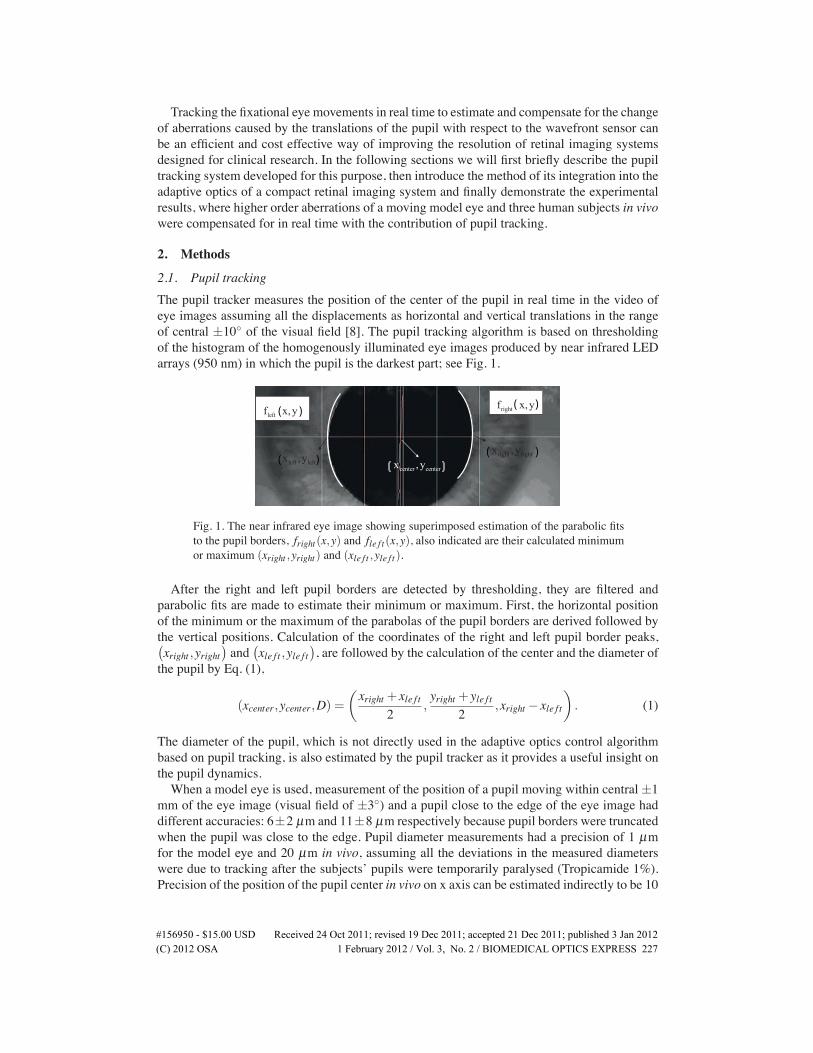
2.1. Pupil trackingThe pupil tracker measures the position of the center of the pupil in real time in the video ofeye images assuming all the displacements as horizontal and vertical translations in the rangeof central ±10◦ of the visual field [8]. The pupil tracking algorithm is based on thresholdingof the histogram of the homogenously illuminated eye images produced by near infrared LEDarrays (950 nm) in which the pupil is the darkest part; see Fig. 1.
center centerx , yright rightx ,y
rightf x, yleftf x, y
left leftx ,y
((
((
))
))
)(
Fig. 1. The near infrared eye image showing superimposed estimation of the parabolic fitsto the pupil borders, fright(x,y) and fle f t(x,y), also indicated are their calculated minimumor maximum (xright ,yright) and (xle f t ,yle f t).
After the right and left pupil borders are detected by thresholding, they are filtered andparabolic fits are made to estimate their minimum or maximum. First, the horizontal positionof the minimum or the maximum of the parabolas of the pupil borders are derived followed bythe vertical positions. Calculation of the coordinates of the right and left pupil border peaks,(
xright ,yright)
and(
xle f t ,yle f t)
, are followed by the calculation of the center and the diameter ofthe pupil by Eq. (1),
(xcenter,ycenter,D) =
(
xright + xle f t2
,yright + yle f t
2,xright − xle f t
)
. (1)
The diameter of the pupil, which is not directly used in the adaptive optics control algorithmbased on pupil tracking, is also estimated by the pupil tracker as it provides a useful insight onthe pupil dynamics.When a model eye is used, measurement of the position of a pupil moving within central±1
mm of the eye image (visual field of ±3◦) and a pupil close to the edge of the eye image haddifferent accuracies: 6±2 µm and 11±8 µm respectively because pupil borders were truncatedwhen the pupil was close to the edge. Pupil diameter measurements had a precision of 1 µmfor the model eye and 20 µm in vivo, assuming all the deviations in the measured diameterswere due to tracking after the subjects’ pupils were temporarily paralysed (Tropicamide 1%).Precision of the position of the pupil center in vivo on x axis can be estimated indirectly to be 10
�����������������86' 5HFHLYHG����2FW�������UHYLVHG����'HF�������DFFHSWHG����'HF�������SXEOLVKHG���-DQ�����(C) 2012 OSA 1 February 2012 / Vol. 3, No. 2 / BIOMEDICAL OPTICS EXPRESS 227
µm, i.e., half of the precision of the pupil diameter in vivo based on the calculation of the pupildiameter in Eq. (1). Misalignment of the eye with respect to the system or a defocused imageof the eye (which is normally corrected by the operator immediately) decreases the sharpnessof the pupil-iris border and contributes to the error of pupil center estimation. The accuracy ofthe pupil tracker when the model eye (focused well at the center of the image) was moved by 5mm forwards and backwards was 15±4 µm [9].The pupil tracker could follow all the drifts and most micro saccades (with speeds up to 50
deg/s on the retina; 25 mm/s on the pupil plane) with its default accuracy as it was estimatedusing a rotating model eye. Its ability to follow fast eye movements was inversely proportionalto the exposure time of the tracking camera as a shorter exposure time means less motion blurin the acquired image. As a result of an unexpected software discrepancy, the pupil trackerwhich worked at ∼ 85 Hz in continuous mode, worked at ∼ 20 Hz when triggered after beingintegrated to the retinal imaging system. The reduction in the execution rate of the tracker wasdue to the processes after the camera exposure, therefore the accuracy of measurements takenduring fast eye movements was not affected. But because of the reduced rate, the pupil trackercould not notify the adaptive optics control algorithm fast enough to compensate for thosemovements on time, the consequences of which will be discussed in the following sections.Commercial eye trackers have moderate accuracies (0.5◦, i.e., approximately 150 microns on
the pupil plane) and span a wide field of view (40◦-50◦) with high rates (500-1000 Hz) at highcosts: in contrast, the pupil tracker described above aims for high accuracy in the short range offixational eye movements at a low price. Although the response time of the pupil tracker needsto be improved, taking into account the present exposure times of the retinal imaging camera,very fast rates of tracking do not seem to be necessary as most of the retinal images acquiredduring fast eye movements suffer from serious motion blur and are eliminated.
2.2. Adaptive opticsThe adaptive optics fundus camera designed for clinical research (rtx1, Imagine Eyes, France)is a compact system that can produce 4◦ × 4◦ high resolution images of the retina, especiallythe cone photoreceptor mosaic [10, 11]. Its adaptive optics comprise a magnetic membranedeformable mirror of 52 actuators, a Shack-Hartmann wavefront sensor with 32× 40 lenslets(mirao 52-e, HASO 32-eye, both from Imagine Eyes, France) and a superluminescent diode of750 nm central wavelength that served the sensor.In a classical adaptive optics correction based on wavefront sensor measurements, the control
algorithm calculates the command vector v to be applied to the deformable mirror at each loop,using the measured slopes vector s of the wavefront as shown in Eq. (2),
v= I†× s, (2)
where I† is the pseudo inverse of the interaction matrix (I) that was recorded before.We developed a new adaptive optics control algorithm based on pupil tracking measurements
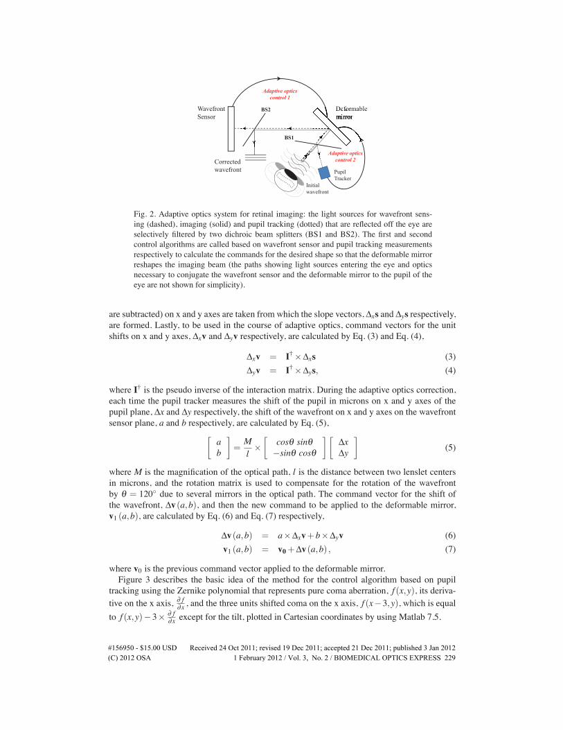
so that the deformable mirror could also work based on pupil tracking, see Sahin et al. [12, 13].Figure 2 shows the basic schematics of the final adaptive optics part of the retinal imagingsystem which has control algorithms based on wavefront sensing and pupil tracking. Both canbe used separately or at the same loop synchronously.
2.3. Adaptive optics with pupil trackingPrior to adaptive optics correction based on pupil tracking, there are a number of steps to betaken. The first one is the measurement of the wavefront aberration profile of the eye, i.e., areference wavefront. Secondly, derivatives of the slopes data of the aberrations measured (afterthe aberrations of the optical path of the imaging system superimposed on the measurements
�����������������86' 5HFHLYHG����2FW�������UHYLVHG����'HF�������DFFHSWHG����'HF�������SXEOLVKHG���-DQ�����(C) 2012 OSA 1 February 2012 / Vol. 3, No. 2 / BIOMEDICAL OPTICS EXPRESS 228
Initialwavefront
Correctedwavefront
WavefrontSensor
Deformablemirror
Adaptive optics
control 1
Deforff mBS2
PupilTracker
BS1
Adaptive optics
control 2
Fig. 2. Adaptive optics system for retinal imaging: the light sources for wavefront sens-ing (dashed), imaging (solid) and pupil tracking (dotted) that are reflected off the eye areselectively filtered by two dichroic beam splitters (BS1 and BS2). The first and secondcontrol algorithms are called based on wavefront sensor and pupil tracking measurementsrespectively to calculate the commands for the desired shape so that the deformable mirrorreshapes the imaging beam (the paths showing light sources entering the eye and opticsnecessary to conjugate the wavefront sensor and the deformable mirror to the pupil of theeye are not shown for simplicity).
are subtracted) on x and y axes are taken from which the slope vectors, Δxs and Δys respectively,are formed. Lastly, to be used in the course of adaptive optics, command vectors for the unitshifts on x and y axes, Δxv and Δyv respectively, are calculated by Eq. (3) and Eq. (4),
Δxv = I†×Δxs (3)Δyv = I†×Δys, (4)
where I† is the pseudo inverse of the interaction matrix. During the adaptive optics correction,each time the pupil tracker measures the shift of the pupil in microns on x and y axes of thepupil plane, Δx and Δy respectively, the shift of the wavefront on x and y axes on the wavefrontsensor plane, a and b respectively, are calculated by Eq. (5),
[
ab
]
=Ml×
[
cosθ sinθ−sinθ cosθ
][
ΔxΔy
]
(5)
where M is the magnification of the optical path, l is the distance between two lenslet centersin microns, and the rotation matrix is used to compensate for the rotation of the wavefrontby θ = 120◦ due to several mirrors in the optical path. The command vector for the shift ofthe wavefront, Δv(a,b), and then the new command to be applied to the deformable mirror,v1 (a,b), are calculated by Eq. (6) and Eq. (7) respectively,
Δv(a,b) = a×Δxv+b×Δyv (6)v1 (a,b) = v0+Δv(a,b) , (7)
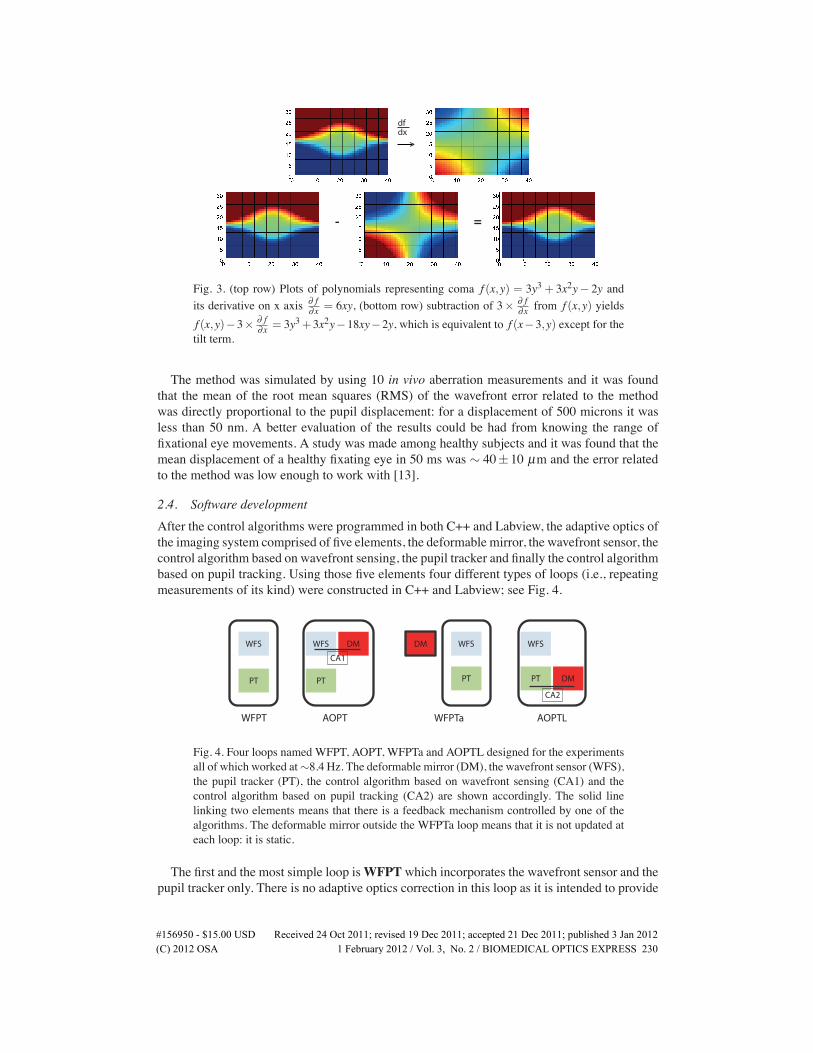
where v0 is the previous command vector applied to the deformable mirror.Figure 3 describes the basic idea of the method for the control algorithm based on pupil
tracking using the Zernike polynomial that represents pure coma aberration, f (x,y), its deriva-tive on the x axis, ∂ f∂x , and the three units shifted coma on the x axis, f (x−3,y), which is equalto f (x,y)−3× ∂ f
∂x except for the tilt, plotted in Cartesian coordinates by using Matlab 7.5.
�����������������86' 5HFHLYHG����2FW�������UHYLVHG����'HF�������DFFHSWHG����'HF�������SXEOLVKHG���-DQ�����(C) 2012 OSA 1 February 2012 / Vol. 3, No. 2 / BIOMEDICAL OPTICS EXPRESS 229
>
dfdx
- =
Fig. 3. (top row) Plots of polynomials representing coma f (x,y) = 3y3 + 3x2y− 2y andits derivative on x axis ∂ f
∂x = 6xy, (bottom row) subtraction of 3× ∂ f∂x from f (x,y) yields
f (x,y)−3× ∂ f∂x = 3y3+3x2y−18xy−2y, which is equivalent to f (x−3,y) except for the
tilt term.
The method was simulated by using 10 in vivo aberration measurements and it was foundthat the mean of the root mean squares (RMS) of the wavefront error related to the methodwas directly proportional to the pupil displacement: for a displacement of 500 microns it wasless than 50 nm. A better evaluation of the results could be had from knowing the range offixational eye movements. A study was made among healthy subjects and it was found that themean displacement of a healthy fixating eye in 50 ms was ∼ 40±10 µm and the error relatedto the method was low enough to work with [13].
2.4. Software developmentAfter the control algorithms were programmed in both C++ and Labview, the adaptive optics ofthe imaging system comprised of five elements, the deformable mirror, the wavefront sensor, thecontrol algorithm based on wavefront sensing, the pupil tracker and finally the control algorithmbased on pupil tracking. Using those five elements four different types of loops (i.e., repeatingmeasurements of its kind) were constructed in C++ and Labview; see Fig. 4.
WFS
PT
WFS
PT
DM WFS
PT
DM WFS
CA1
PT DM
CA2
WFPT AOPT WFPTa AOPTL
Fig. 4. Four loops named WFPT, AOPT, WFPTa and AOPTL designed for the experimentsall of which worked at∼8.4 Hz. The deformable mirror (DM), the wavefront sensor (WFS),the pupil tracker (PT), the control algorithm based on wavefront sensing (CA1) and thecontrol algorithm based on pupil tracking (CA2) are shown accordingly. The solid linelinking two elements means that there is a feedback mechanism controlled by one of thealgorithms. The deformable mirror outside the WFPTa loop means that it is not updated ateach loop: it is static.
The first and the most simple loop isWFPTwhich incorporates the wavefront sensor and thepupil tracker only. There is no adaptive optics correction in this loop as it is intended to provide
�����������������86' 5HFHLYHG����2FW�������UHYLVHG����'HF�������DFFHSWHG����'HF�������SXEOLVKHG���-DQ�����(C) 2012 OSA 1 February 2012 / Vol. 3, No. 2 / BIOMEDICAL OPTICS EXPRESS 230
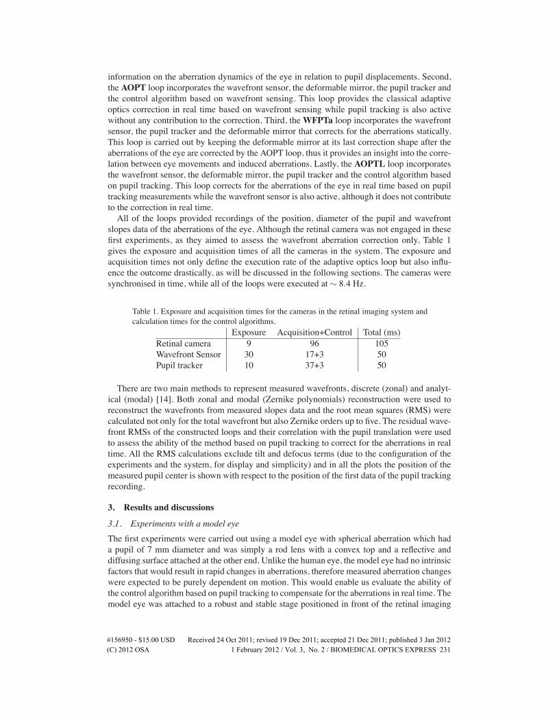
information on the aberration dynamics of the eye in relation to pupil displacements. Second,the AOPT loop incorporates the wavefront sensor, the deformable mirror, the pupil tracker andthe control algorithm based on wavefront sensing. This loop provides the classical adaptiveoptics correction in real time based on wavefront sensing while pupil tracking is also activewithout any contribution to the correction. Third, theWFPTa loop incorporates the wavefrontsensor, the pupil tracker and the deformable mirror that corrects for the aberrations statically.This loop is carried out by keeping the deformable mirror at its last correction shape after theaberrations of the eye are corrected by the AOPT loop, thus it provides an insight into the corre-lation between eye movements and induced aberrations. Lastly, the AOPTL loop incorporatesthe wavefront sensor, the deformable mirror, the pupil tracker and the control algorithm basedon pupil tracking. This loop corrects for the aberrations of the eye in real time based on pupiltracking measurements while the wavefront sensor is also active, although it does not contributeto the correction in real time.All of the loops provided recordings of the position, diameter of the pupil and wavefront
slopes data of the aberrations of the eye. Although the retinal camera was not engaged in thesefirst experiments, as they aimed to assess the wavefront aberration correction only, Table 1gives the exposure and acquisition times of all the cameras in the system. The exposure andacquisition times not only define the execution rate of the adaptive optics loop but also influ-ence the outcome drastically, as will be discussed in the following sections. The cameras weresynchronised in time, while all of the loops were executed at ∼ 8.4 Hz.
Table 1. Exposure and acquisition times for the cameras in the retinal imaging system andcalculation times for the control algorithms.
Exposure Acquisition+Control Total (ms)Retinal camera 9 96 105Wavefront Sensor 30 17+3 50Pupil tracker 10 37+3 50
There are two main methods to represent measured wavefronts, discrete (zonal) and analyt-ical (modal) [14]. Both zonal and modal (Zernike polynomials) reconstruction were used toreconstruct the wavefronts from measured slopes data and the root mean squares (RMS) werecalculated not only for the total wavefront but also Zernike orders up to five. The residual wave-front RMSs of the constructed loops and their correlation with the pupil translation were usedto assess the ability of the method based on pupil tracking to correct for the aberrations in realtime. All the RMS calculations exclude tilt and defocus terms (due to the configuration of theexperiments and the system, for display and simplicity) and in all the plots the position of themeasured pupil center is shown with respect to the position of the first data of the pupil trackingrecording.
3. Results and discussions
3.1. Experiments with a model eyeThe first experiments were carried out using a model eye with spherical aberration which hada pupil of 7 mm diameter and was simply a rod lens with a convex top and a reflective anddiffusing surface attached at the other end. Unlike the human eye, the model eye had no intrinsicfactors that would result in rapid changes in aberrations, therefore measured aberration changeswere expected to be purely dependent on motion. This would enable us evaluate the ability ofthe control algorithm based on pupil tracking to compensate for the aberrations in real time. Themodel eye was attached to a robust and stable stage positioned in front of the retinal imaging
�����������������86' 5HFHLYHG����2FW�������UHYLVHG����'HF�������DFFHSWHG����'HF�������SXEOLVKHG���-DQ�����(C) 2012 OSA 1 February 2012 / Vol. 3, No. 2 / BIOMEDICAL OPTICS EXPRESS 231
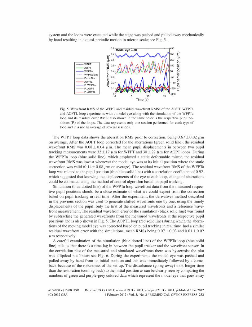
system and the loops were executed while the stage was pushed and pulled away mechanicallyby hand resulting in a quasi-periodic motion in micron scale; see Fig. 5.
0 5 10 150
0.1
0.2
0.3
0.4
0.5
0.6
0.7
0.8
Wav
efro
nt R
MS
(µm
)
Time (s)
Model eye − all
Model eye − all
−350
−250
−150
−50
50
150
250
350
450
Pupi
l cen
ter p
ositi
on (µ
m)
WFPTAOPTWFPTaWFPTa Sim.Error Sim.AOPTLP. WFPTaP. AOPTP. AOPTL
Fig. 5. Wavefront RMS of the WFPT and residual wavefront RMSs of the AOPT, WFPTaand AOPTL loop experiments with a model eye along with the simulation of the WFPTaloop and its residual error RMS; also shown in the same color is the respective pupil po-sitions (P.) of the loops. The data represents only one session performed for each type ofloop and it is not an average of several sessions.
The WFPT loop data shows the aberration RMS prior to correction, being 0.67± 0.02 µmon average. After the AOPT loop corrected for the aberrations (green solid line), the residualwavefront RMS was 0.08± 0.04 µm. The mean pupil displacements in between two pupiltracking measurements were 32±17 µm for WFPT and 30±22 µm for AOPT loops. Duringthe WFPTa loop (blue solid line), which employed a static deformable mirror, the residualwavefront RMS was lowest whenever the model eye was at its initial position where the staticcorrection was valid (0.14±0.08 µm on average). The residual wavefront RMS of the WFPTaloop was related to the pupil position (thin blue solid line) with a correlation coefficient of 0.92,which suggested that knowing the displacements of the eye at each loop, change of aberrationscould be estimated using the method of control algorithm based on pupil tracking.Simulation (blue dotted line) of the WFPTa loop wavefront data from the measured respec-
tive pupil positions should be a close estimate of what we could expect from the correctionbased on pupil tracking in real time. After the experiment, the derivatives method describedin the previous section was used to generate shifted wavefronts one by one, using the timelydisplacements of the pupil, only the first of the measured wavefronts and a reference wave-front measurement. The residual wavefront error of the simulation (black solid line) was foundby subtracting the generated wavefronts from the measured wavefronts at the respective pupilpositions and is also shown in Fig. 5. The AOPTL loop (red solid line) during which the aberra-tions of the moving model eye was corrected based on pupil tracking in real time, had a similarresidual wavefront error with the simulations, mean RMSs being 0.07± 0.03 and 0.01± 0.02µm respectively.A careful examination of the simulation (blue dotted line) of the WFPTa loop (blue solid
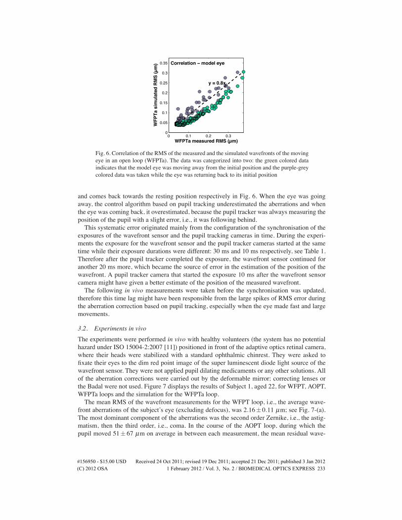
line) tells us that there is a time lag in between the pupil tracker and the wavefront sensor. Inthe correlation plot of the measured and simulated wavefronts there was hysteresis: the plotwas elliptical not linear; see Fig. 6. During the experiments the model eye was pushed andpulled away by hand from its initial position and this was immediately followed by a come-back because of the robustness of the set up. The disturbance (going away) took longer timethan the restoration (coming back) to the initial position as can be clearly seen by comparing thenumbers of green and purple-grey colored data which represent the model eye that goes away
�����������������86' 5HFHLYHG����2FW�������UHYLVHG����'HF�������DFFHSWHG����'HF�������SXEOLVKHG���-DQ�����(C) 2012 OSA 1 February 2012 / Vol. 3, No. 2 / BIOMEDICAL OPTICS EXPRESS 232
0 0.1 0.2 0.30
0.05
0.1
0.15
0.2
0.25
0.3
0.35
WFPTa measured RMS (µm)
WFP
Ta s
imul
ated
RM
S (µ
m)
y = 0.8x
Correlation − model eye
Fig. 6. Correlation of the RMS of the measured and the simulated wavefronts of the movingeye in an open loop (WFPTa). The data was categorized into two: the green colored dataindicates that the model eye was moving away from the initial position and the purple-greycolored data was taken while the eye was returning back to its initial position
and comes back towards the resting position respectively in Fig. 6. When the eye was goingaway, the control algorithm based on pupil tracking underestimated the aberrations and whenthe eye was coming back, it overestimated, because the pupil tracker was always measuring theposition of the pupil with a slight error, i.e., it was following behind.This systematic error originated mainly from the configuration of the synchronisation of the
exposures of the wavefront sensor and the pupil tracking cameras in time. During the experi-ments the exposure for the wavefront sensor and the pupil tracker cameras started at the sametime while their exposure durations were different: 30 ms and 10 ms respectively, see Table 1.Therefore after the pupil tracker completed the exposure, the wavefront sensor continued foranother 20 ms more, which became the source of error in the estimation of the position of thewavefront. A pupil tracker camera that started the exposure 10 ms after the wavefront sensorcamera might have given a better estimate of the position of the measured wavefront.The following in vivo measurements were taken before the synchronisation was updated,
therefore this time lag might have been responsible from the large spikes of RMS error duringthe aberration correction based on pupil tracking, especially when the eye made fast and largemovements.
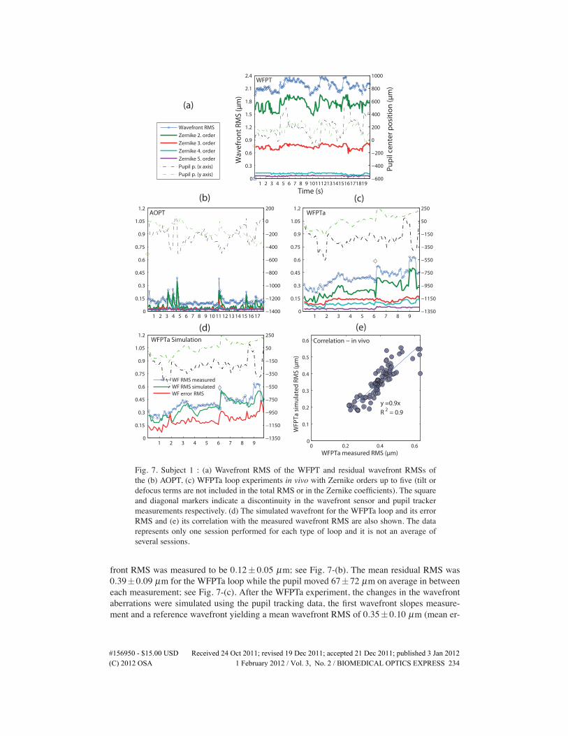
3.2. Experiments in vivoThe experiments were performed in vivo with healthy volunteers (the system has no potentialhazard under ISO 15004-2:2007 [11]) positioned in front of the adaptive optics retinal camera,where their heads were stabilized with a standard ophthalmic chinrest. They were asked tofixate their eyes to the dim red point image of the super luminescent diode light source of thewavefront sensor. They were not applied pupil dilating medicaments or any other solutions. Allof the aberration corrections were carried out by the deformable mirror; correcting lenses orthe Badal were not used. Figure 7 displays the results of Subject 1, aged 22, for WFPT, AOPT,WFPTa loops and the simulation for the WFPTa loop.The mean RMS of the wavefront measurements for the WFPT loop, i.e., the average wave-
front aberrations of the subject’s eye (excluding defocus), was 2.16±0.11 µm; see Fig. 7-(a).The most dominant component of the aberrations was the second order Zernike, i.e., the astig-matism, then the third order, i.e., coma. In the course of the AOPT loop, during which thepupil moved 51± 67 µm on average in between each measurement, the mean residual wave-
�����������������86' 5HFHLYHG����2FW�������UHYLVHG����'HF�������DFFHSWHG����'HF�������SXEOLVKHG���-DQ�����(C) 2012 OSA 1 February 2012 / Vol. 3, No. 2 / BIOMEDICAL OPTICS EXPRESS 233
0
0.3
0.6
0.9
1.2
1.5
1.8
2.1
2.4
Wav
efro
nt
RM
S (µ
m)
WFPT
1 2 3 4 5 6 7 8 9 10111213141516171819−600
−400
−200
0
200
400
600
800
1000
Pu
pil
cen
ter
po
siti
on
(µm
)
Time (s)
Wavefront RMS
Zernike 2. order
Zernike 3. order
Zernike 4. order
Zernike 5. order
Pupil p. (x axis)
Pupil p. (y axis)
0
0.15
0.3
0.45
0.6
0.75
0.9
1.05
1.2AOPT
1 2 3 4 5 6 7 8 9 10 11 12 13 14 15 16 17−1400
−1200
−1000
−800
−600
−400
−200
0
200
0
0.15
0.3
0.45
0.6
0.75
0.9
1.05
1.2WFPTa
1 2 3 4 5 6 7 8 9−1350
−1150
−950
−750
−550
−350
−150
50
250
(a)
(b) (c)
0
0.15
0.3
0.45
0.6
0.75
0.9
1.05
1.2
WFPTa Simulation
1 2 3 4 5 6 7 8 9−1350
−1150
−950
−750
−550
−350
−150
50
250
WF RMS measuredWF RMS simulatedWF erro RMSr
0 0.2 0.4 0.60
0.1
0.2
0.3
0.4
0.5
0.6
WFPTa measured RMS (µm)
WFP
Ta s
imu
late
d R
MS
(µm
)
y =0.9x
R2 = 0.9
Correlation − in vivo
(d) (e)
Fig. 7. Subject 1 : (a) Wavefront RMS of the WFPT and residual wavefront RMSs ofthe (b) AOPT, (c) WFPTa loop experiments in vivo with Zernike orders up to five (tilt ordefocus terms are not included in the total RMS or in the Zernike coefficients). The squareand diagonal markers indicate a discontinuity in the wavefront sensor and pupil trackermeasurements respectively. (d) The simulated wavefront for the WFPTa loop and its errorRMS and (e) its correlation with the measured wavefront RMS are also shown. The datarepresents only one session performed for each type of loop and it is not an average ofseveral sessions.
front RMS was measured to be 0.12± 0.05 µm; see Fig. 7-(b). The mean residual RMS was0.39±0.09 µm for the WFPTa loop while the pupil moved 67±72 µm on average in betweeneach measurement; see Fig. 7-(c). After the WFPTa experiment, the changes in the wavefrontaberrations were simulated using the pupil tracking data, the first wavefront slopes measure-ment and a reference wavefront yielding a mean wavefront RMS of 0.35±0.10 µm (mean er-
�����������������86' 5HFHLYHG����2FW�������UHYLVHG����'HF�������DFFHSWHG����'HF�������SXEOLVKHG���-DQ�����(C) 2012 OSA 1 February 2012 / Vol. 3, No. 2 / BIOMEDICAL OPTICS EXPRESS 234
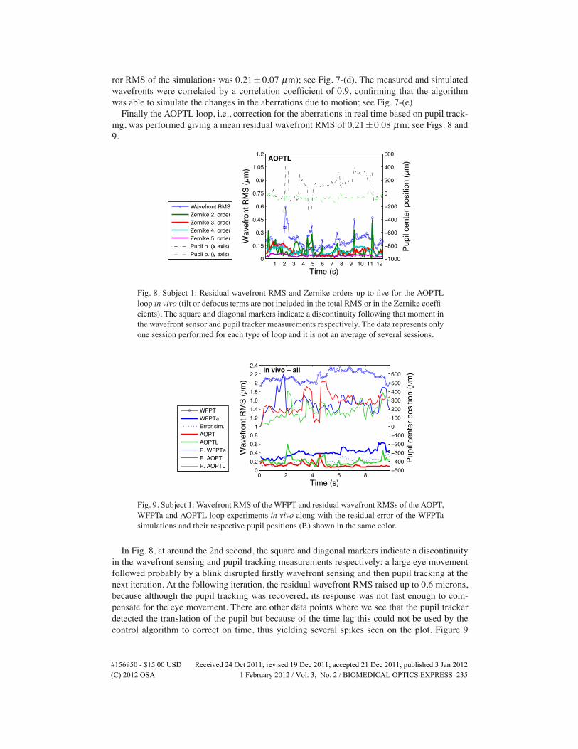
ror RMS of the simulations was 0.21±0.07 µm); see Fig. 7-(d). The measured and simulatedwavefronts were correlated by a correlation coefficient of 0.9, confirming that the algorithmwas able to simulate the changes in the aberrations due to motion; see Fig. 7-(e).Finally the AOPTL loop, i.e., correction for the aberrations in real time based on pupil track-
ing, was performed giving a mean residual wavefront RMS of 0.21±0.08 µm; see Figs. 8 and9.
0
0.15
0.3
0.45
0.6
0.75
0.9
1.05
1.2
Wav
efro
nt R
MS
(µm
)
AOPTL
1 2 3 4 5 6 7 8 9 10 11 12−1000
−800
−600
−400
−200
0
200
400
600
Pupi
l cen
ter p
ositi
on (µ
m)
Time (s)
Wavefront RMSZernike 2. orderZernike 3. orderZernike 4. orderZernike 5. orderPupil p. (x axis)Pupil p. (y axis)
Fig. 8. Subject 1: Residual wavefront RMS and Zernike orders up to five for the AOPTLloop in vivo (tilt or defocus terms are not included in the total RMS or in the Zernike coeffi-cients). The square and diagonal markers indicate a discontinuity following that moment inthe wavefront sensor and pupil tracker measurements respectively. The data represents onlyone session performed for each type of loop and it is not an average of several sessions.
0 2 4 6 80
0.20.40.60.8
11.21.41.61.8
22.22.4
Wav
efro
nt R
MS
(µm
)
Time (s)
Subject 1 − all
In vivo − all
−500−400−300−200−1000100200300400500600
Pupi
l cen
ter p
ositi
on (µ
m)
WFPTWFPTaError sim.AOPTAOPTLP. WFPTaP. AOPTP. AOPTL
Fig. 9. Subject 1: Wavefront RMS of the WFPT and residual wavefront RMSs of the AOPT,WFPTa and AOPTL loop experiments in vivo along with the residual error of the WFPTasimulations and their respective pupil positions (P.) shown in the same color.
In Fig. 8, at around the 2nd second, the square and diagonal markers indicate a discontinuityin the wavefront sensing and pupil tracking measurements respectively: a large eye movementfollowed probably by a blink disrupted firstly wavefront sensing and then pupil tracking at thenext iteration. At the following iteration, the residual wavefront RMS raised up to 0.6 microns,because although the pupil tracking was recovered, its response was not fast enough to com-pensate for the eye movement. There are other data points where we see that the pupil trackerdetected the translation of the pupil but because of the time lag this could not be used by thecontrol algorithm to correct on time, thus yielding several spikes seen on the plot. Figure 9
�����������������86' 5HFHLYHG����2FW�������UHYLVHG����'HF�������DFFHSWHG����'HF�������SXEOLVKHG���-DQ�����(C) 2012 OSA 1 February 2012 / Vol. 3, No. 2 / BIOMEDICAL OPTICS EXPRESS 235
shows the in vivo experimental results for Subject 1 for their first nine seconds. Except for thespikes, the AOPTL loop correction was comparable to the AOPT loop, i.e., the correction donebased on wavefront sensing, demonstrating that pupil tracking can be used as an active opticalelement in wavefront correction.
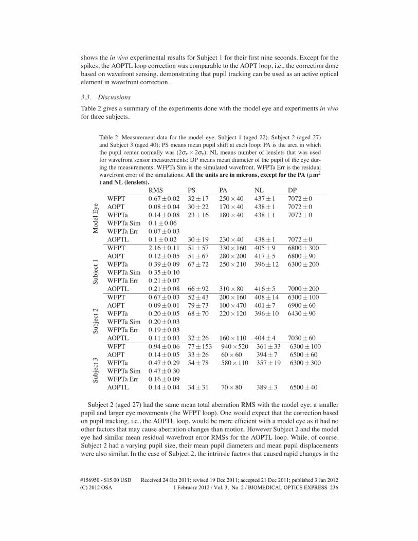
3.3. DiscussionsTable 2 gives a summary of the experiments done with the model eye and experiments in vivofor three subjects.
Table 2. Measurement data for the model eye, Subject 1 (aged 22), Subject 2 (aged 27)and Subject 3 (aged 40); PS means mean pupil shift at each loop; PA is the area in whichthe pupil center normally was (2σx× 2σy); NL means number of lenslets that was usedfor wavefront sensor measurements; DP means mean diameter of the pupil of the eye dur-ing the measurements; WFPTa Sim is the simulated wavefront, WFPTa Err is the residualwavefront error of the simulations. All the units are in microns, except for the PA (µm2) and NL (lenslets).
ModelEye
RMS PS PA NL DPWFPT 0.67±0.02 32±17 250×40 437±1 7072±0AOPT 0.08±0.04 30±22 170×40 438±1 7072±0WFPTa 0.14±0.08 23±16 180×40 438±1 7072±0WFPTa Sim 0.1±0.06WFPTa Err 0.07±0.03AOPTL 0.1±0.02 30±19 230×40 438±1 7072±0
Subject1
WFPT 2.16±0.11 51±57 330×160 405±9 6800±300AOPT 0.12±0.05 51±67 280×200 417±5 6800±90WFPTa 0.39±0.09 67±72 250×210 396±12 6300±200WFPTa Sim 0.35±0.10WFPTa Err 0.21±0.07AOPTL 0.21±0.08 66±92 310×80 416±5 7000±200
Subject2
WFPT 0.67±0.03 52±43 200×160 408±14 6300±100AOPT 0.09±0.01 79±73 100×470 401±7 6900±60WFPTa 0.20±0.05 68±70 220×120 396±10 6430±90WFPTa Sim 0.20±0.03WFPTa Err 0.19±0.03AOPTL 0.11±0.03 32±26 160×110 404±4 7030±60
Subject3
WFPT 0.94±0.06 77±153 940×520 361±33 6300±100AOPT 0.14±0.05 33±26 60×60 394±7 6500±60WFPTa 0.47±0.29 54±78 580×110 357±19 6300±300WFPTa Sim 0.47±0.30WFPTa Err 0.16±0.09AOPTL 0.14±0.04 34±31 70×80 389±3 6500±40
Subject 2 (aged 27) had the same mean total aberration RMS with the model eye; a smallerpupil and larger eye movements (the WFPT loop). One would expect that the correction basedon pupil tracking, i.e., the AOPTL loop, would be more efficient with a model eye as it had noother factors that may cause aberration changes than motion. However Subject 2 and the modeleye had similar mean residual wavefront error RMSs for the AOPTL loop. While, of course,Subject 2 had a varying pupil size, their mean pupil diameters and mean pupil displacementswere also similar. In the case of Subject 2, the intrinsic factors that caused rapid changes in the
�����������������86' 5HFHLYHG����2FW�������UHYLVHG����'HF�������DFFHSWHG����'HF�������SXEOLVKHG���-DQ�����(C) 2012 OSA 1 February 2012 / Vol. 3, No. 2 / BIOMEDICAL OPTICS EXPRESS 236
higher order aberrations were minor. Simulations for the Subject 2 had a large residual errorRMS (0.19± 0.03 µm) due probably to a wrong choice of reference wavefront that did notrepresent the aberrations of the eye successfully. Choice of the reference wavefront is crucial forthe algorithm to estimate the displaced wavefronts. Subject 3 (aged 40) had equal residual meanaberration RMSs for the AOPT and AOPTL loops. In this case, the performance of the AOPTloop, i.e., the correction based on wavefront sensing, was below the average, due probably to awrong wavefront sensor measurement at the beginning of the iterations.There is room for improvements: the error of compensation would be smaller by improv-
ing the speed and the accuracy of pupil tracking, decreasing the error related to method andof course a better configuration of camera exposures and timing. These experiments were per-formed after the reference wavefronts were chosen subjectively: an automatic program thatwould choose the reference wavefront objectively might assure the success of the algorithm. Aselective correction of aberrations might also be applied as the error in pupil center measure-ments is translated into the wavefront error differently depending on the irregularity of theaberration: the sensitivity to translation and rotation is different for different aberration terms[15].Although, eye movements are essentially rotations, the pupil tracker, in the short range of fix-
ational eye movements, assumes them to be translations. The error related to this may increaseby large eye movements and can be overcome by tracking not only the position but also therotation of the eye. Another important error source might be the fact that the subjects were notcyclopleged to paralyse the accommodation temporarily. Changes in the shape of the lens in-troduce not only defocus (the term which we excluded from the calculated RMS) but also otherhigher order aberrations such as astigmatism. Changes in the aberrations caused by this andother intrinsic factors or the tear film cannot be detected or compensated for by the algorithmbased on pupil tracking and are sources of error. A pupil larger than the entrance pupil of theimaging system (of 6 mm diameter) is also a source of error because the reference wavefrontthat is used as a base for the algorithm does not fully represent the aberrations of the eye and ismissing the parts truncated by the entrance pupil of the system.Although defocus term is not included in the calculated RMSs and there is not enough data to
make a statistical analysis and arrive to a conclusion on the percentage of the aberration changesthat can be corrected based on pupil tracking, the data presented is promising. The proposedmethod is not superior to the classical correction, when used alone, but adaptive optics maybe improved when pupil tracking is used in collaboration with wavefront sensing. This is themajor purpose of this research and is detailed in the following section.
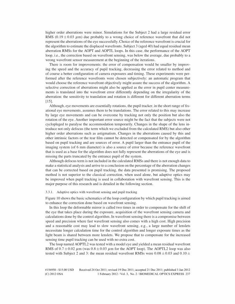
3.3.1. Adaptive optics with wavefront sensing and pupil tracking
Figure 10 shows the basic schematics of the loop configuration by which pupil tracking is aimedto enhance the correction done based on wavefront sensing.In this loop the deformable mirror is called two times in order to compensate for the shift of
the eye that takes place during the exposure, acquisition of the wavefront sensing camera andcalculations done by the control algorithm. In wavefront sensing there is a compromise betweenspeed and precision where fast wavefront sensing also comes with a high cost. High precisionand a reasonable cost may lead to slow wavefront sensing, e.g., a large number of lensletsnecessitate longer calculation time for the control algorithm and longer exposure times as thelight beam is shared between more lenslets. We propose that to compensate for the increasedsensing time pupil tracking can be used with no extra cost.The loop named AOPTL2 was tested with a model eye and yielded a mean residual wavefront
RMS of 0.7± 0.02 µm (was 0.8± 0.03 µm for the AOPT loop). The AOPTL2 loop was alsotested with Subject 2 and 3: the mean residual wavefront RMSs were 0.08± 0.03 and 0.10±
�����������������86' 5HFHLYHG����2FW�������UHYLVHG����'HF�������DFFHSWHG����'HF�������SXEOLVKHG���-DQ�����(C) 2012 OSA 1 February 2012 / Vol. 3, No. 2 / BIOMEDICAL OPTICS EXPRESS 237
WFS
PT
DM
CA1
PT
DM
AOPTL2
Fig. 10. The adaptive optics loop which incorporates all the active elements: the deformablemirror (DM), the wavefront sensor (WFS), the pupil tracker (PT), the control algorithmbased on wavefront sensing (CA1) and the control algorithm based on pupil tracking (CA2),where the pupil tracker and the deformable mirror is called two times in a loop. The solidline linking the elements means that there is a feedback mechanism controlled by one ofthe algorithms.
0.06 µm while the eyes moved 32±26 and 50±65 µm with mean pupil diameters of 6000±300 and 7000±100 µm respectively. When compared to the AOPT loop, i.e., correction basedonly on wavefront sensing, the AOPTL2 loop did not yield a significant enhancement. We owethis to the low speed (20 Hz when triggered) of the pupil tracker and the time lag discussedin the previous section. With improvements, this method is hoped to increase the stability andperformance capabilities of the adaptive optics correction for retinal imaging with no extra cost.The outcome might be a more robust system where deformable mirror is immunized to headand eye movements and there is less need for a bite bar which might be uncomfortable for theelderly and the children in the clinical environment.
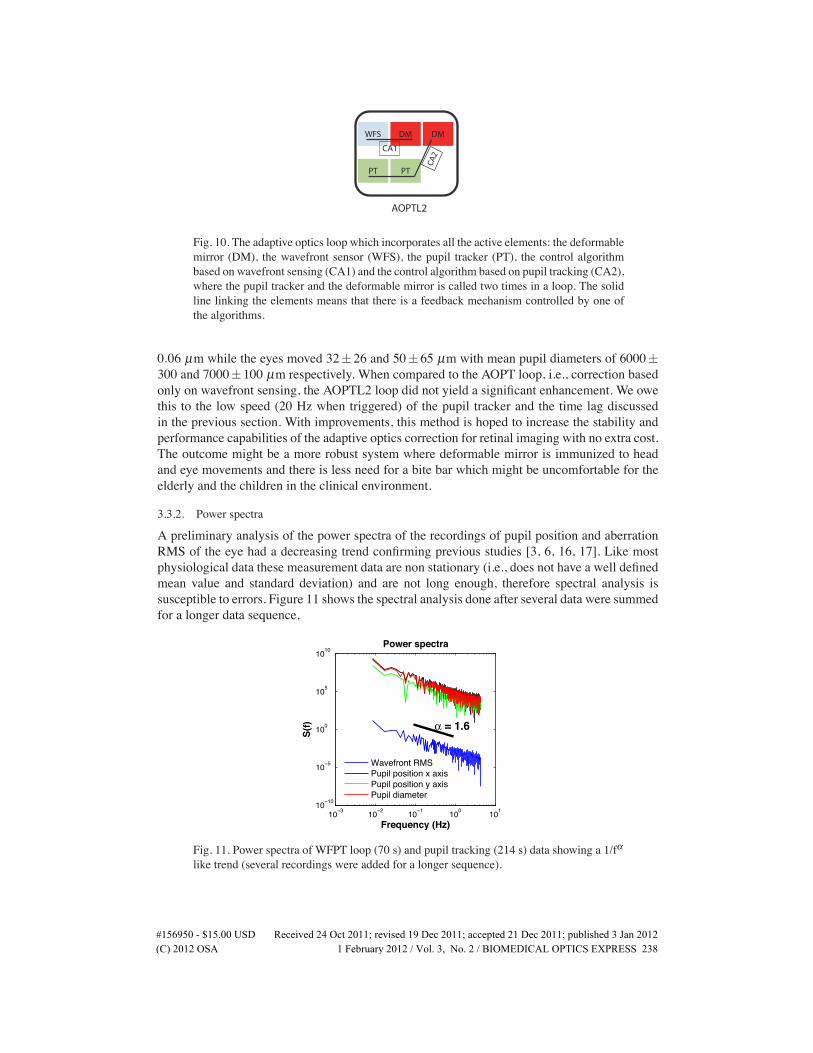
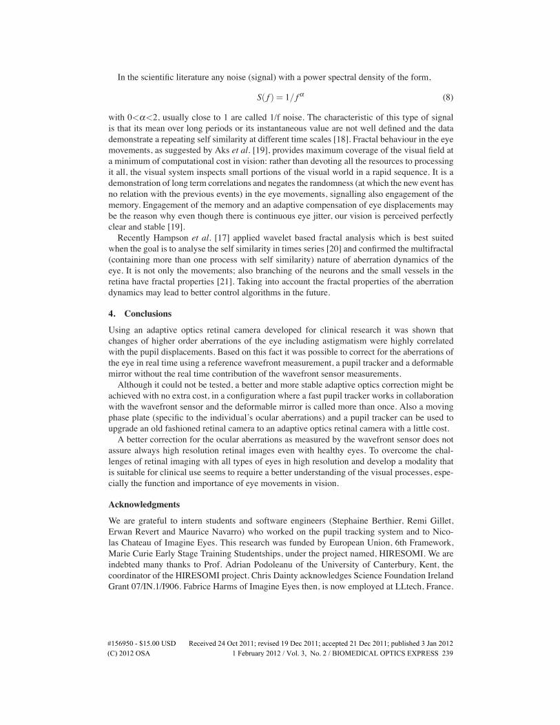
3.3.2. Power spectra
A preliminary analysis of the power spectra of the recordings of pupil position and aberrationRMS of the eye had a decreasing trend confirming previous studies [3, 6, 16, 17]. Like mostphysiological data these measurement data are non stationary (i.e., does not have a well definedmean value and standard deviation) and are not long enough, therefore spectral analysis issusceptible to errors. Figure 11 shows the spectral analysis done after several data were summedfor a longer data sequence.
10−3 10−2 10−1 100 10110−10
10−5
100
105
1010
Frequency (Hz)
S(f)
Power spectra
α = 1.6
Wavefront RMSPupil position x axisPupil position y axisPupil diameter
Fig. 11. Power spectra of WFPT loop (70 s) and pupil tracking (214 s) data showing a 1/fαlike trend (several recordings were added for a longer sequence).
�����������������86' 5HFHLYHG����2FW�������UHYLVHG����'HF�������DFFHSWHG����'HF�������SXEOLVKHG���-DQ�����(C) 2012 OSA 1 February 2012 / Vol. 3, No. 2 / BIOMEDICAL OPTICS EXPRESS 238
In the scientific literature any noise (signal) with a power spectral density of the form,
S( f ) = 1/ f α (8)
with 0<α<2, usually close to 1 are called 1/f noise. The characteristic of this type of signalis that its mean over long periods or its instantaneous value are not well defined and the datademonstrate a repeating self similarity at different time scales [18]. Fractal behaviour in the eyemovements, as suggested by Aks et al. [19], provides maximum coverage of the visual field ata minimum of computational cost in vision: rather than devoting all the resources to processingit all, the visual system inspects small portions of the visual world in a rapid sequence. It is ademonstration of long term correlations and negates the randomness (at which the new event hasno relation with the previous events) in the eye movements, signalling also engagement of thememory. Engagement of the memory and an adaptive compensation of eye displacements maybe the reason why even though there is continuous eye jitter, our vision is perceived perfectlyclear and stable [19].Recently Hampson et al. [17] applied wavelet based fractal analysis which is best suited
when the goal is to analyse the self similarity in times series [20] and confirmed the multifractal(containing more than one process with self similarity) nature of aberration dynamics of theeye. It is not only the movements; also branching of the neurons and the small vessels in theretina have fractal properties [21]. Taking into account the fractal properties of the aberrationdynamics may lead to better control algorithms in the future.
4. Conclusions
Using an adaptive optics retinal camera developed for clinical research it was shown thatchanges of higher order aberrations of the eye including astigmatism were highly correlatedwith the pupil displacements. Based on this fact it was possible to correct for the aberrations ofthe eye in real time using a reference wavefront measurement, a pupil tracker and a deformablemirror without the real time contribution of the wavefront sensor measurements.Although it could not be tested, a better and more stable adaptive optics correction might be
achieved with no extra cost, in a configuration where a fast pupil tracker works in collaborationwith the wavefront sensor and the deformable mirror is called more than once. Also a movingphase plate (specific to the individual’s ocular aberrations) and a pupil tracker can be used toupgrade an old fashioned retinal camera to an adaptive optics retinal camera with a little cost.A better correction for the ocular aberrations as measured by the wavefront sensor does not
assure always high resolution retinal images even with healthy eyes. To overcome the chal-lenges of retinal imaging with all types of eyes in high resolution and develop a modality thatis suitable for clinical use seems to require a better understanding of the visual processes, espe-cially the function and importance of eye movements in vision.
Acknowledgments
We are grateful to intern students and software engineers (Stephaine Berthier, Remi Gillet,Erwan Revert and Maurice Navarro) who worked on the pupil tracking system and to Nico-las Chateau of Imagine Eyes. This research was funded by European Union, 6th Framework,Marie Curie Early Stage Training Studentships, under the project named, HIRESOMI. We areindebted many thanks to Prof. Adrian Podoleanu of the University of Canterbury, Kent, thecoordinator of the HIRESOMI project. Chris Dainty acknowledges Science Foundation IrelandGrant 07/IN.1/I906. Fabrice Harms of Imagine Eyes then, is now employed at LLtech, France.
�����������������86' 5HFHLYHG����2FW�������UHYLVHG����'HF�������DFFHSWHG����'HF�������SXEOLVKHG���-DQ�����(C) 2012 OSA 1 February 2012 / Vol. 3, No. 2 / BIOMEDICAL OPTICS EXPRESS 239