Embed Size (px)
Citation preview
Designing Adaptive Optics Systems
Donald GavelUCO/Lick Observatory
Laboratory for Adaptive Optics
8/13/03 CfAO Summer School August 2003 2
Designing Adaptive Optics Systems
Outline
• The design process
• AO systems taxonomy– Commonalities and differences among systems
• Single-conjugate adaptive optics for astronomy
• Vision systems• Communications systems
• Multi-conjugate adaptive optics
• Specific design examples– Lick laser guidestar
– Keck laser guidestar– CELT MCAO
• Summary
8/13/03 CfAO Summer School August 2003 3
The Design Process• Science Requirements and Conceptual Design
– Response to a need
– Preliminary Proposal
• Conceptual Design Review (CoDR)– Estabilishes basic system architecture and scope of costs– Request funding for a detailed design phase
• Preliminary Design Review (PDR)– More details of design
– Solved issues– Risk reduction plan– Project plan through CDR, scope overall project plan
• Critical Design Review (CDR)– Components & vendors identified
– Completed design drawings– Build commences
• Pre-ship Review
• Commissioning
8/13/03 CfAO Summer School August 2003 4
What do AO systems do?
• Correct aberrated wavefronts for sharper images
• Astronomy: compensate for the atmospheric distortions
• Vision: compensate for the aberrations in the lens, cornea, and
vitreous volume
– Image the retina at high resolution
– Improve vision beyond 20/20
• Communication: keep the beam on the receiver’s detector,
lower the bit error rate
• Lasers: confine the beam’s power onto a target
8/13/03 CfAO Summer School August 2003 5
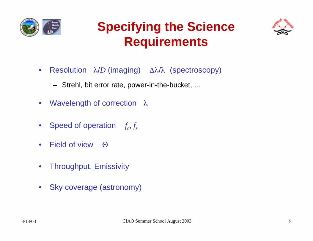
Specifying the ScienceRequirements
• Resolution λ/D (imaging) ∆λ/λ (spectroscopy)
– Strehl, bit error rate, power-in-the-bucket, ...
• Wavelength of correction λ
• Speed of operation fc, fs
• Field of view Θ
• Throughput, Emissivity
• Sky coverage (astronomy)
8/13/03 CfAO Summer School August 2003 6
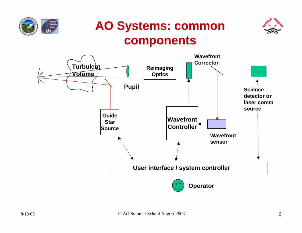
AO Systems: commoncomponents
TurbulentVolume
GuideStar
Source
Pupil
WavefrontCorrector
ReimagingOptics
Wavefrontsensor
WavefrontController
Operator
User interface / system controller
Sciencedetector orlaser commsource
8/13/03 CfAO Summer School August 2003 7
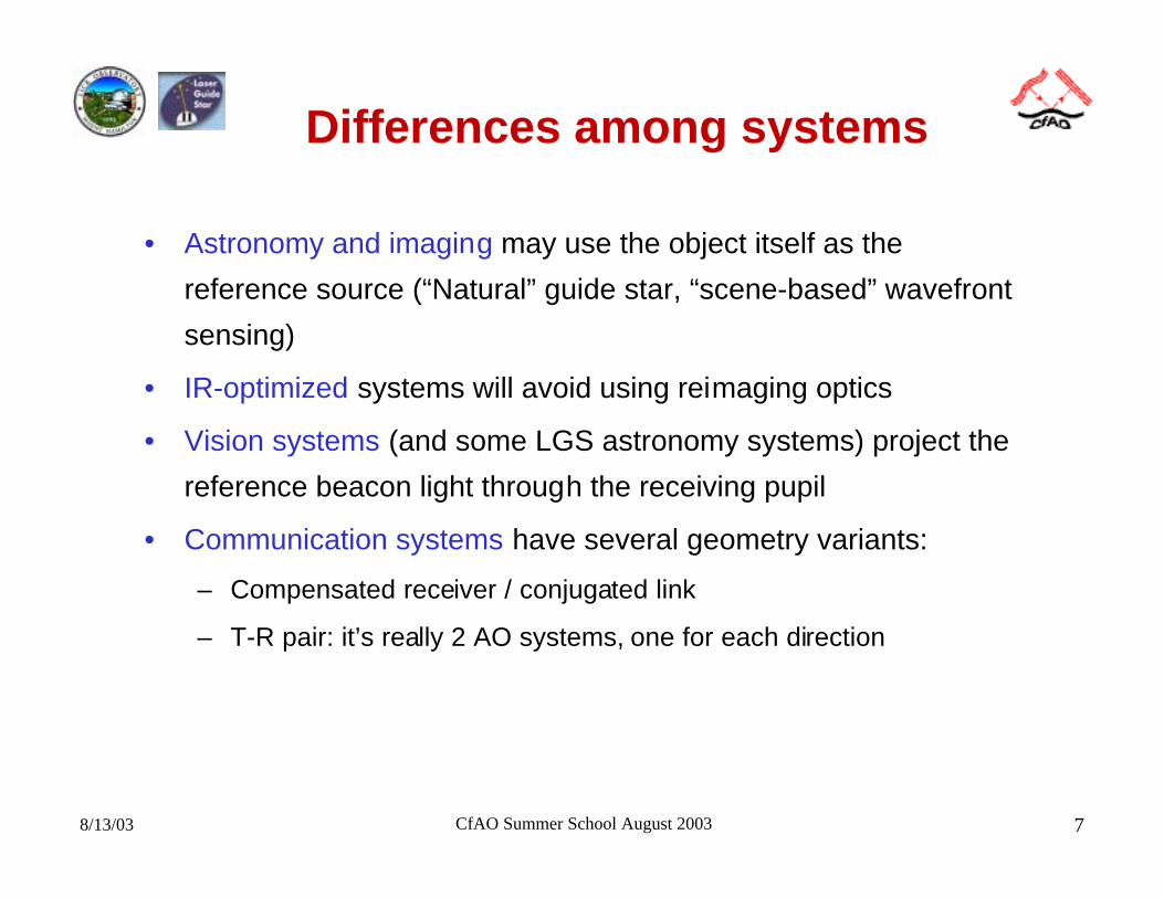
Differences among systems
• Astronomy and imaging may use the object itself as the
reference source (“Natural” guide star, “scene-based” wavefront
sensing)
• IR-optimized systems will avoid using reimaging optics
• Vision systems (and some LGS astronomy systems) project the
reference beacon light through the receiving pupil
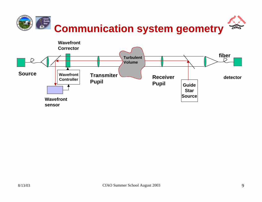
• Communication systems have several geometry variants:
– Compensated receiver / conjugated link
– T-R pair: it’s really 2 AO systems, one for each direction
8/13/03 CfAO Summer School August 2003 8
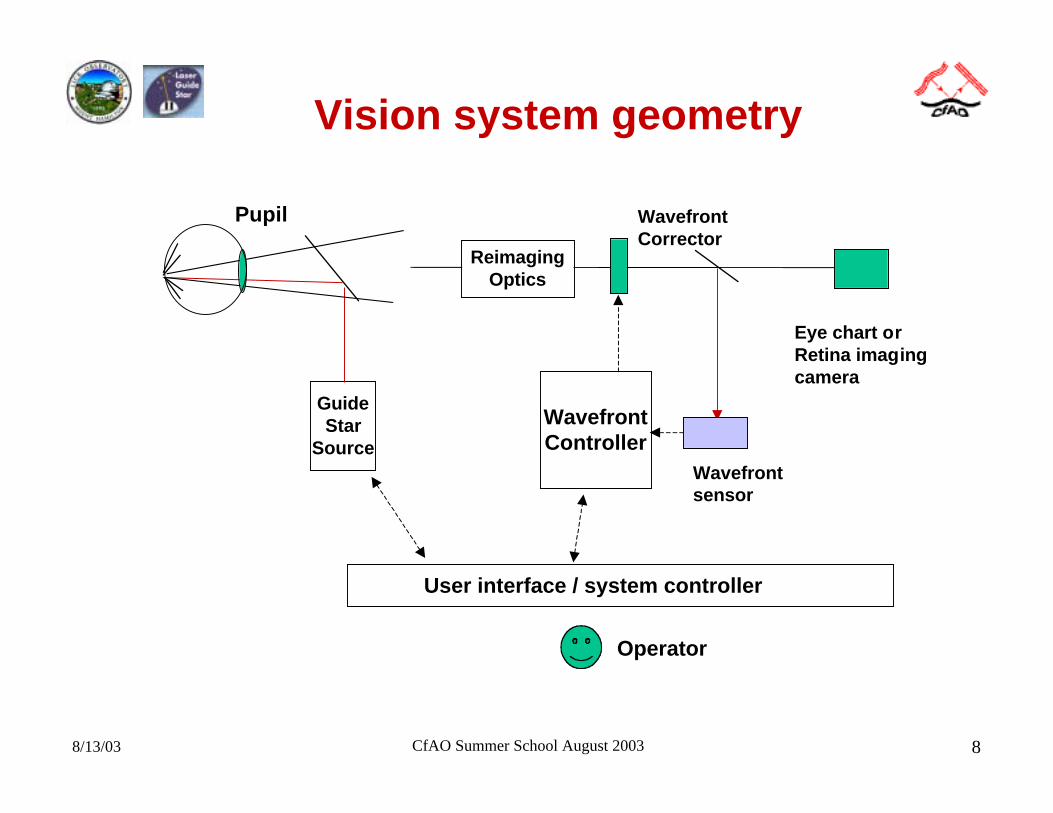
Vision system geometry
GuideStar
Source
Pupil WavefrontCorrector
ReimagingOptics
Wavefrontsensor
WavefrontController
Operator
User interface / system controller
Eye chart orRetina imagingcamera
8/13/03 CfAO Summer School August 2003 9
Communication system geometry
GuideStar
Source
ReceiverPupil
WavefrontCorrector
Wavefrontsensor
WavefrontController detector
fiberTurbulentVolume
Source TransmiterPupil
8/13/03 CfAO Summer School August 2003 10
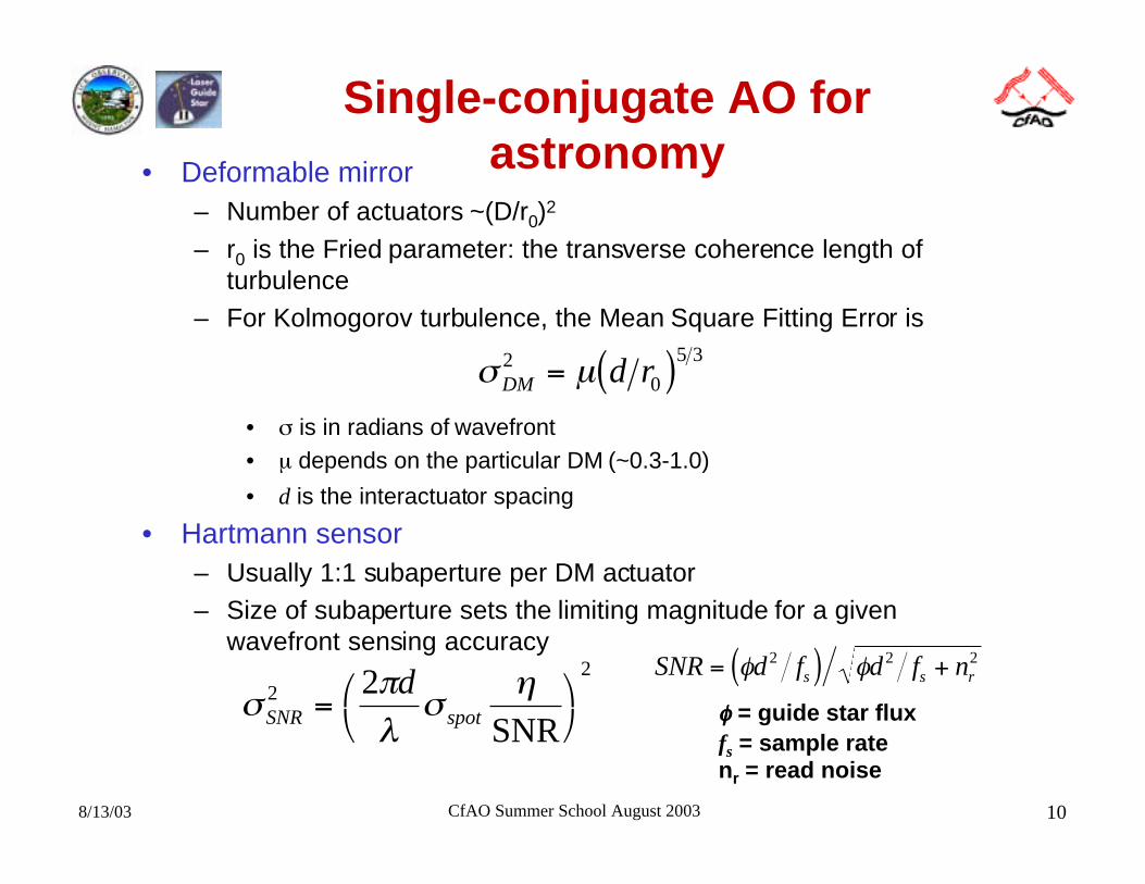
Single-conjugate AO forastronomy• Deformable mirror
– Number of actuators ~(D/r0)2
– r0 is the Fried parameter: the transverse coherence length ofturbulence
– For Kolmogorov turbulence, the Mean Square Fitting Error is
• σ is in radians of wavefront• µ depends on the particular DM (~0.3-1.0)
• d is the interactuator spacing
• Hartmann sensor– Usually 1:1 subaperture per DM actuator– Size of subaperture sets the limiting magnitude for a given
wavefront sensing accuracy
σ µDM d r20
5 3= ( )
σπλ
ση
SNR spot
d222
=
SNR
SNR d f d f ns s r= ( ) +φ φ2 2 2
φφφφ = guide star fluxfs = sample ratenr = read noise
8/13/03 CfAO Summer School August 2003 11
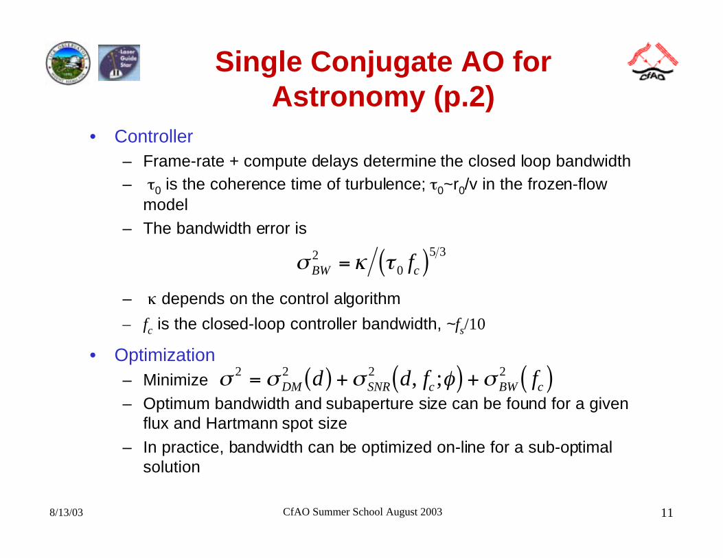
Single Conjugate AO forAstronomy (p.2)
• Controller– Frame-rate + compute delays determine the closed loop bandwidth– τ0 is the coherence time of turbulence; τ0~r0/v in the frozen-flow
model– The bandwidth error is
– κ depends on the control algorithm
– fc is the closed-loop controller bandwidth, ~fs/10
• Optimization– Minimize– Optimum bandwidth and subaperture size can be found for a given
flux and Hartmann spot size
– In practice, bandwidth can be optimized on-line for a sub-optimalsolution
σ κ τBW cf2
0
5 3= ( )
σ σ σ φ σ2 2 2 2= ( ) + ( ) + ( )DM SNR c BW cd d f f, ;
8/13/03 CfAO Summer School August 2003 12
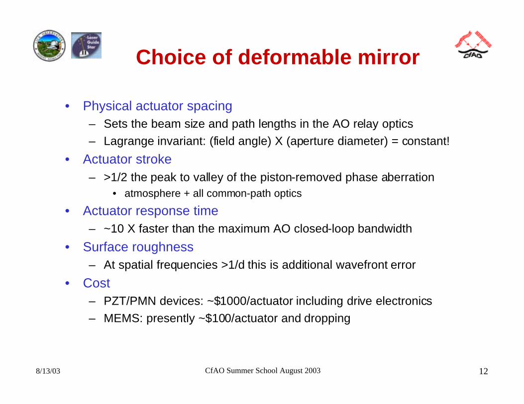
Choice of deformable mirror
• Physical actuator spacing– Sets the beam size and path lengths in the AO relay optics
– Lagrange invariant: (field angle) X (aperture diameter) = constant!
• Actuator stroke– >1/2 the peak to valley of the piston-removed phase aberration
• atmosphere + all common-path optics
• Actuator response time– ~10 X faster than the maximum AO closed-loop bandwidth
• Surface roughness– At spatial frequencies >1/d this is additional wavefront error
• Cost– PZT/PMN devices: ~$1000/actuator including drive electronics
– MEMS: presently ~$100/actuator and dropping
8/13/03 CfAO Summer School August 2003 13
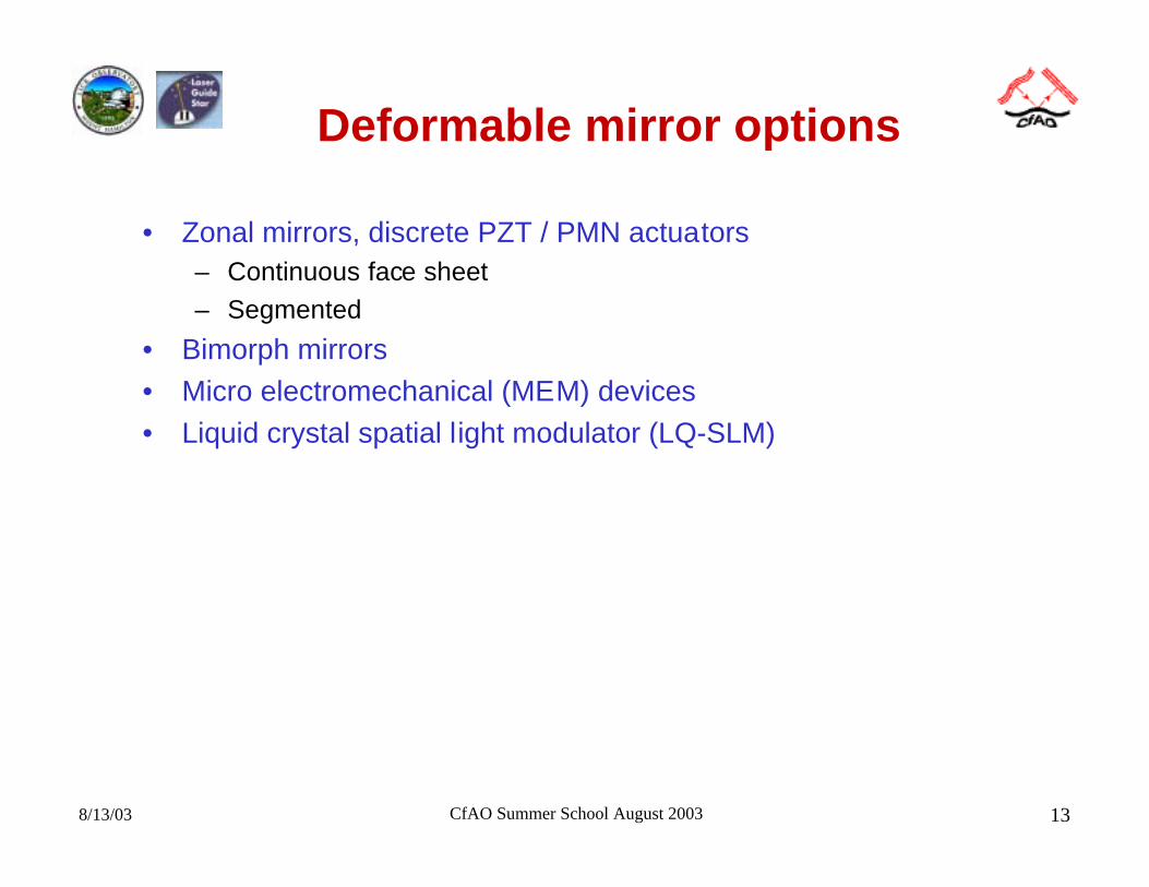
Deformable mirror options
• Zonal mirrors, discrete PZT / PMN actuators– Continuous face sheet
– Segmented
• Bimorph mirrors
• Micro electromechanical (MEM) devices
• Liquid crystal spatial light modulator (LQ-SLM)
8/13/03 CfAO Summer School August 2003 14
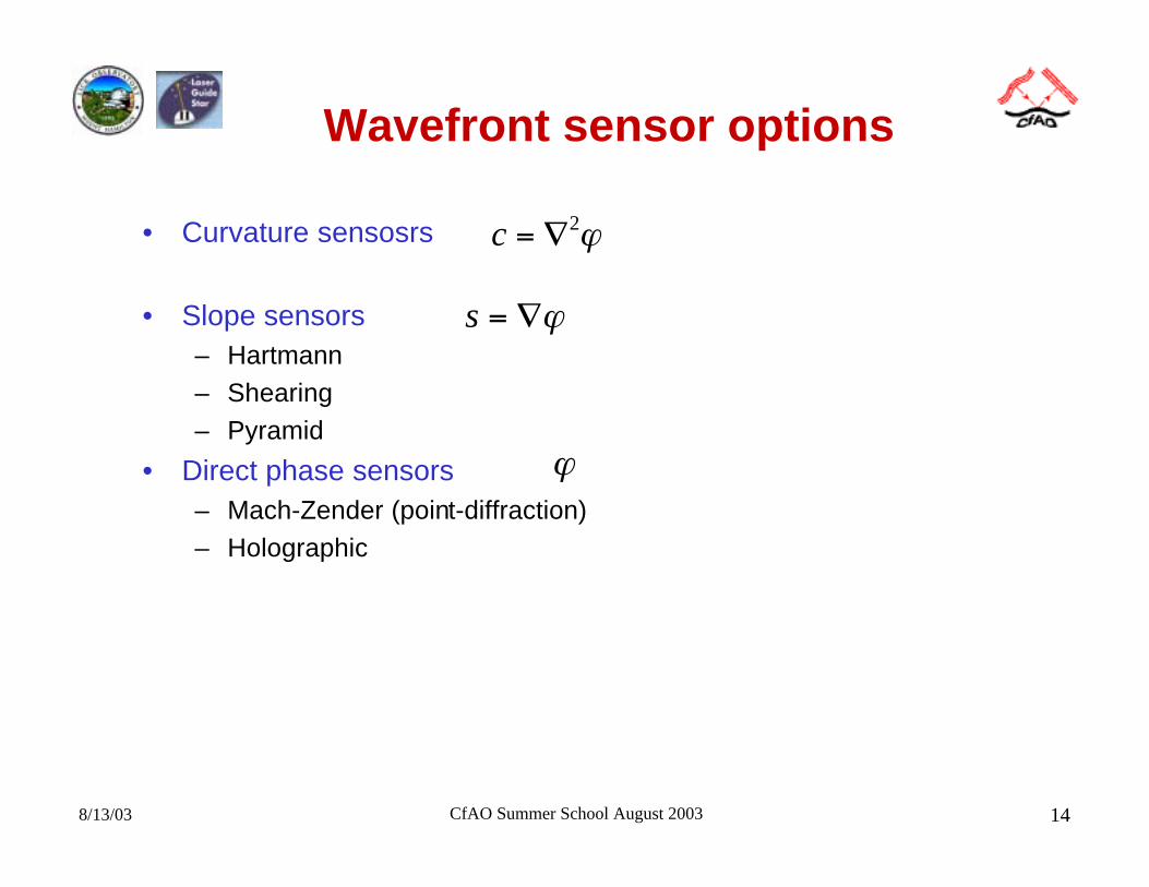
Wavefront sensor options
• Curvature sensosrs
• Slope sensors– Hartmann– Shearing– Pyramid
• Direct phase sensors– Mach-Zender (point-diffraction)– Holographic
c = ∇2ϕ
s = ∇ϕ
ϕ
8/13/03 CfAO Summer School August 2003 15
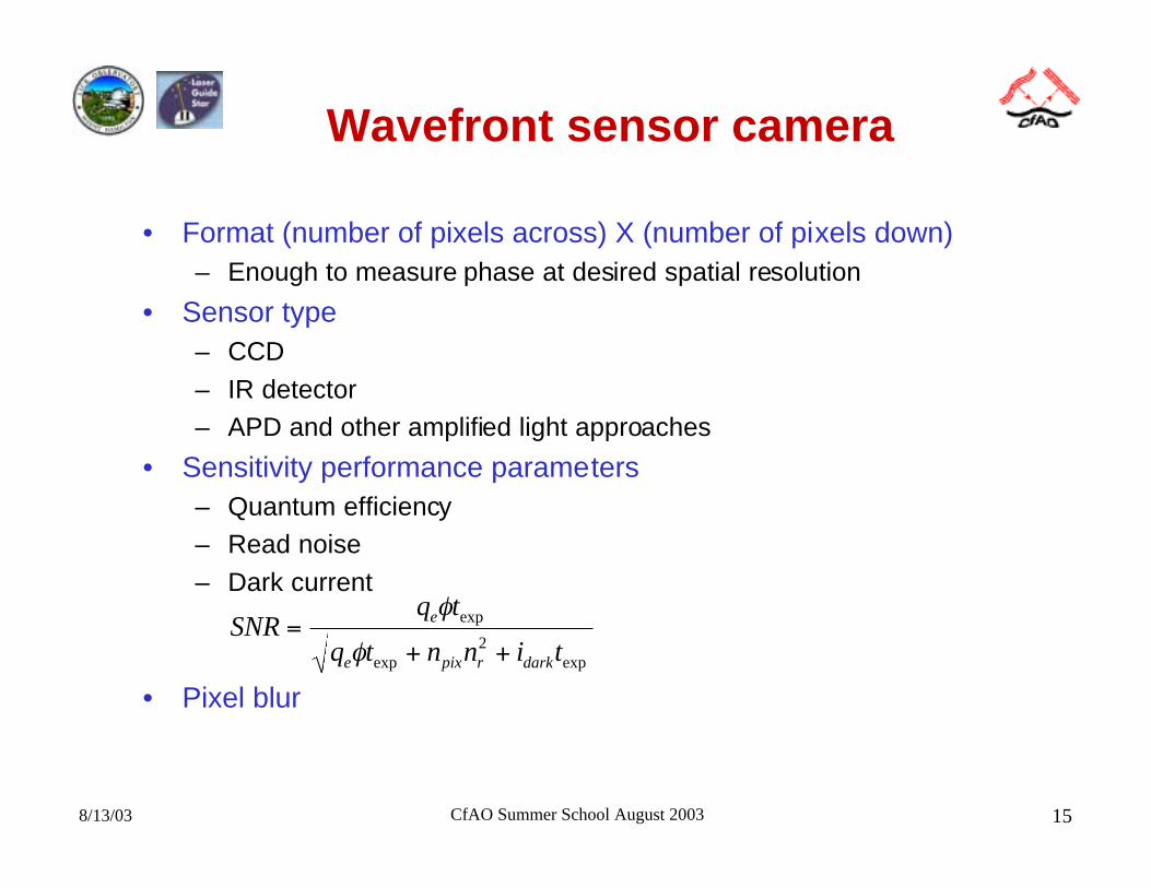
Wavefront sensor camera
• Format (number of pixels across) X (number of pixels down)– Enough to measure phase at desired spatial resolution
• Sensor type– CCD
– IR detector– APD and other amplified light approaches
• Sensitivity performance parameters– Quantum efficiency– Read noise
– Dark current
• Pixel blur
SNRq t
q t n n i t
e
e pix r dark
=+ +
φ
φexp
exp exp2
8/13/03 CfAO Summer School August 2003 16
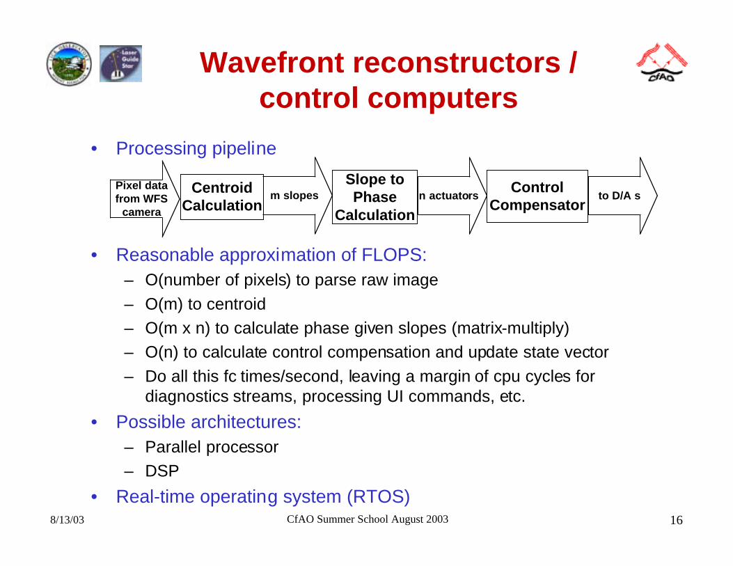
Wavefront reconstructors /control computers
• Processing pipeline
• Reasonable approximation of FLOPS:– O(number of pixels) to parse raw image
– O(m) to centroid– O(m x n) to calculate phase given slopes (matrix-multiply)– O(n) to calculate control compensation and update state vector
– Do all this fc times/second, leaving a margin of cpu cycles fordiagnostics streams, processing UI commands, etc.
• Possible architectures:– Parallel processor– DSP
• Real-time operating system (RTOS)
CentroidCalculation
Slope toPhase
Calculation
ControlCompensator
Pixel datafrom WFS
camera
m slopes n actuators to D/A s
8/13/03 CfAO Summer School August 2003 17
Wavefront reconstructors /control computers (p.2)
• Diagnostics and Telemetry– Bursts of data at full frame-rate for later diagnostic analysis
• WFS pixels
• Centroids, intensities• Actuator commands
– Periodic status update for the user interface• Centroid & intensity display
• User Interface / System Controller (UISC)– Graphical user interface (GUI) controls
• Open/close AO loops• Field-steering
• Other optics bench support: ND filters, fiber calibration sources, etc.
• Analysis support– r0 and wind speed calculator
– Closed-loop point spread function (PSF) estimation
8/13/03 CfAO Summer School August 2003 18
Vision adaptive optics systems
• Is there an r0 for the eye?
• Beacon (guide star)– Coherence. Broad bandwidth superluminescent diode reduces
speckle in the Hartmann subapertures– Corneal reflection (ghost)
– Collimation/focus– Light budget
• Maximum eye exposure• Wavelength
• Choice of beam splitters
• Eye motion / Pupil tracking
• Deformable mirrors– Conventional– MEMS
– LQ-SLM
8/13/03 CfAO Summer School August 2003 19
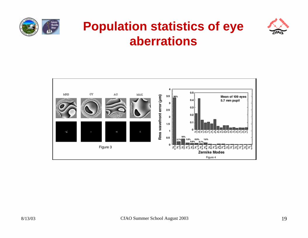
Population statistics of eyeaberrations
8/13/03 CfAO Summer School August 2003 20
Communications systems• Characteristics
– Objective is to minimize bit error rate (BER) in free-space point-to-point communications
• Equivalent to maximizing power in the bucket• Minimum BER allows higher communications bandwidth
– Turbulence is spread out along path– Narrow field of view
• Design (DARPA/CCIT)– Pre-compensation at transmitter end– Holographic wavefront sensor
• Direct phase measuring
– Piston-only segmented DM– Massively parallel control algorithm
• Design (AOptix)– Curvature sensing– Curvature MEMS
8/13/03 CfAO Summer School August 2003 21
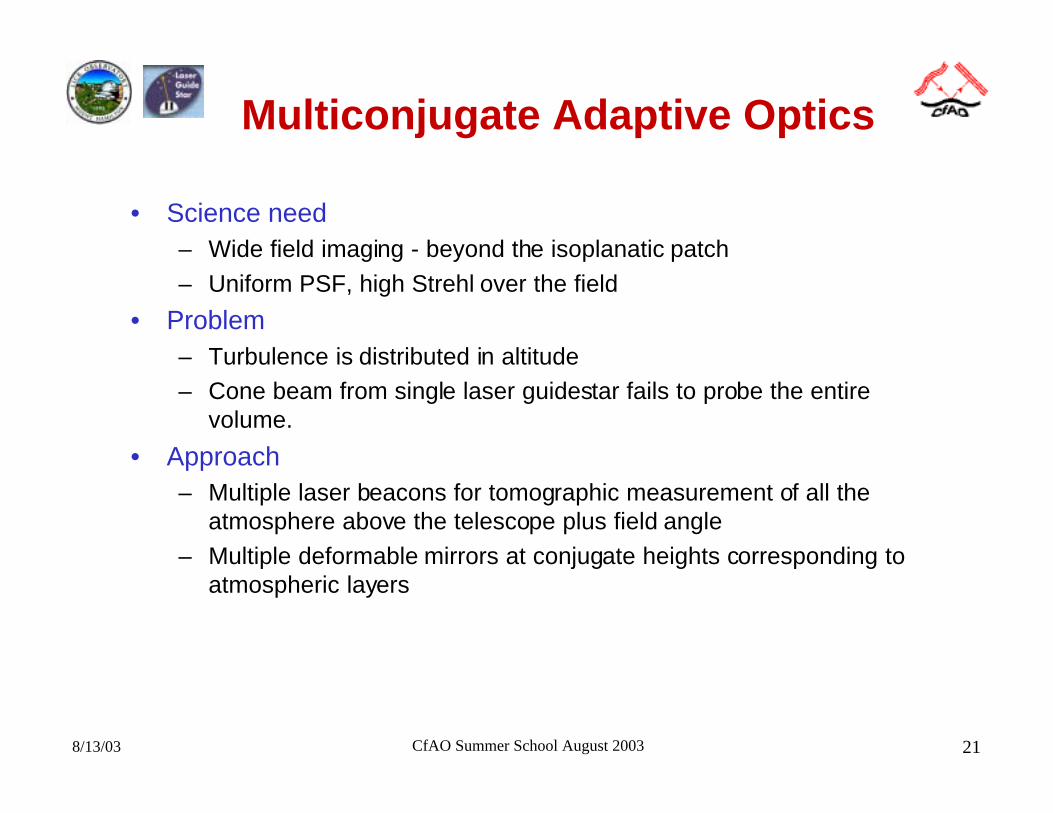
Multiconjugate Adaptive Optics
• Science need– Wide field imaging - beyond the isoplanatic patch
– Uniform PSF, high Strehl over the field
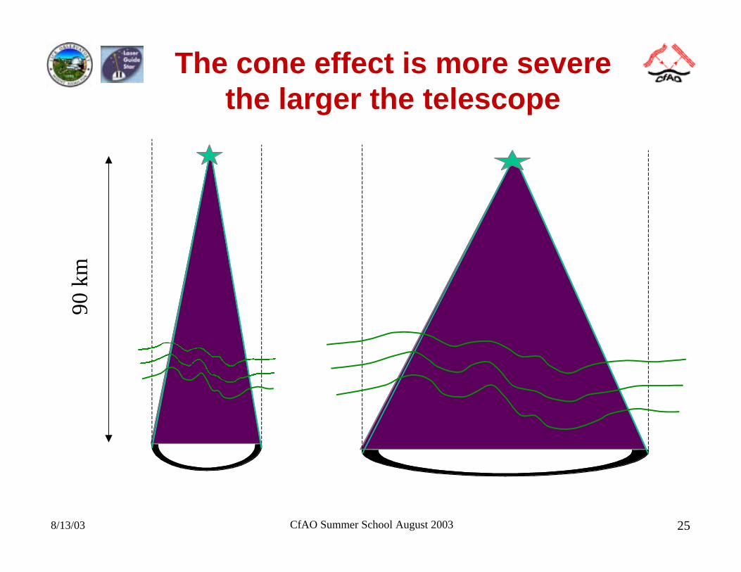
• Problem– Turbulence is distributed in altitude– Cone beam from single laser guidestar fails to probe the entire
volume.
• Approach– Multiple laser beacons for tomographic measurement of all the
atmosphere above the telescope plus field angle
– Multiple deformable mirrors at conjugate heights corresponding toatmospheric layers
8/13/03 CfAO Summer School August 2003 22
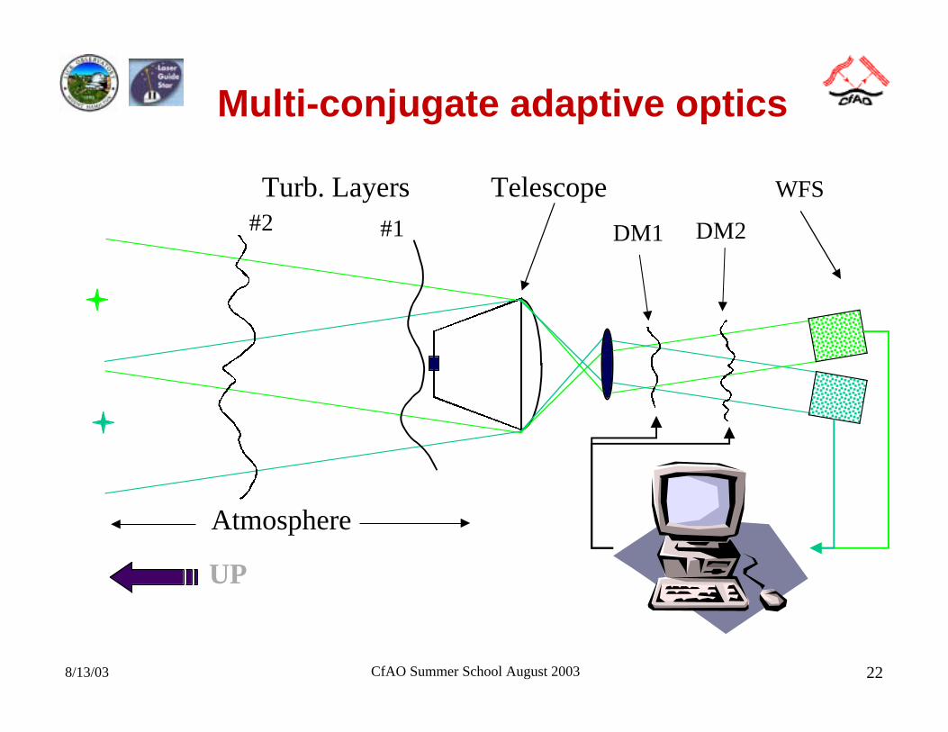
Multi-conjugate adaptive optics
Telescope
DM1 DM2
Turb. Layers#2 #1
Atmosphere
WFS
UP
8/13/03 CfAO Summer School August 2003 23
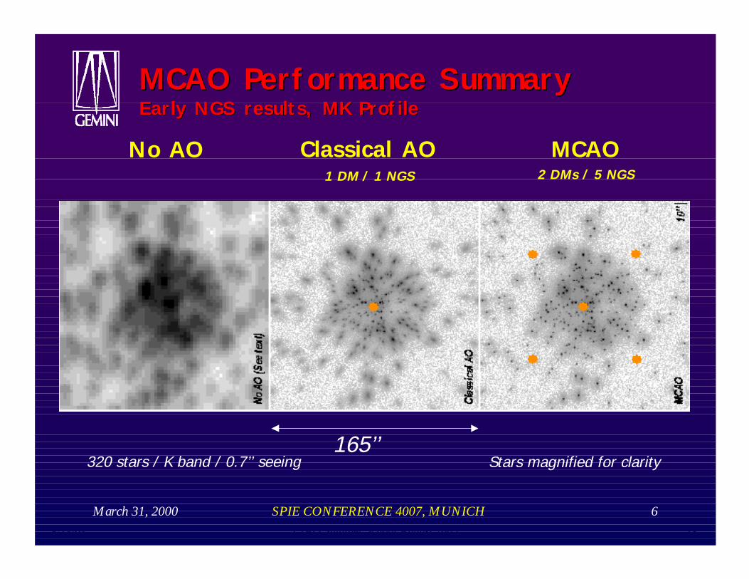
March 31, 2000 SPIE CONFERENCE 4007, MUNICH 6
Classical AO MCAONo AO
165’’
MCAO Performance SummaryMCAO Performance SummaryEarly NGS results, MK ProfileEarly NGS results, MK Profile
2 DMs / 5 NGS
320 stars / K band / 0.7’’ seeing
1 DM / 1 NGS
Stars magnified for clarity
8/13/03 CfAO Summer School August 2003 24
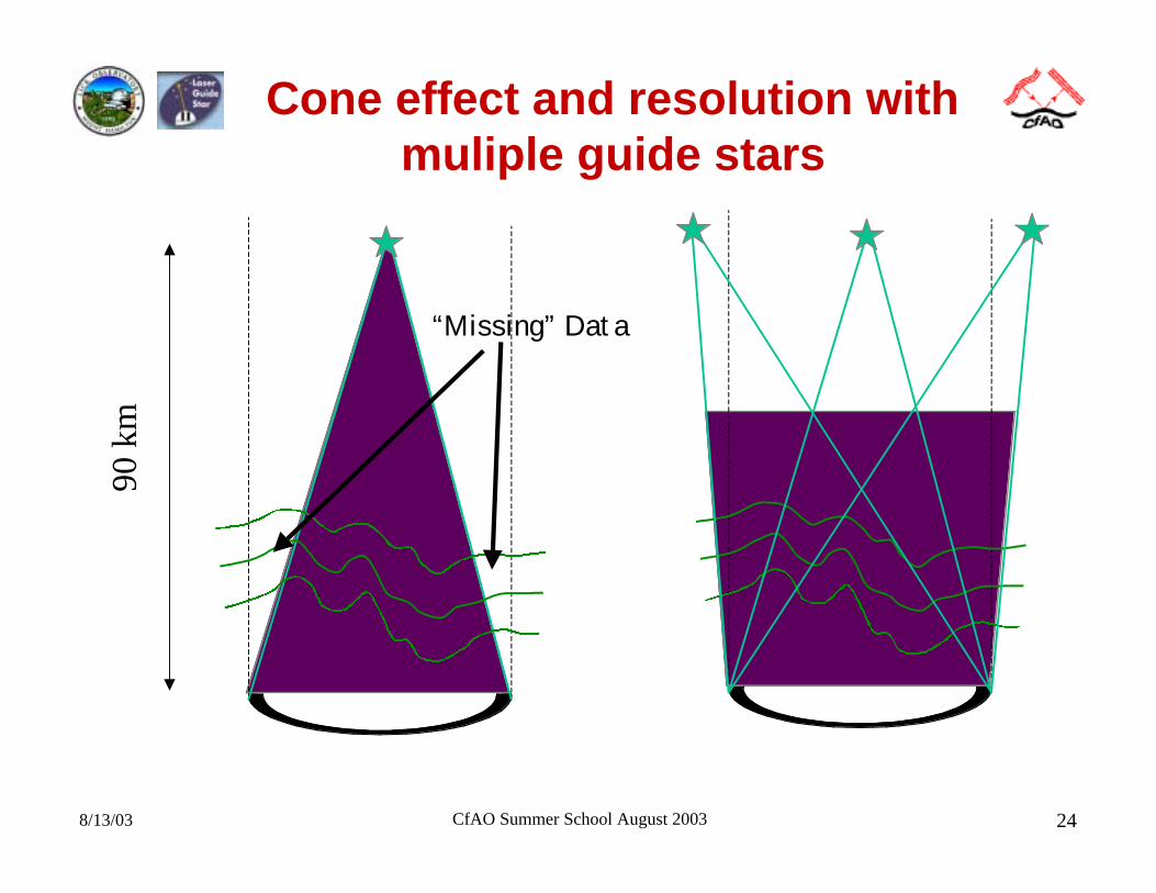
Cone effect and resolution withmuliple guide stars90
km
“Missing” Data
8/13/03 CfAO Summer School August 2003 25
The cone effect is more severethe larger the telescope
90 k
m
8/13/03 CfAO Summer School August 2003 26
MCAO design parameter space
• Number and placement of laser guide stars
• Number of DMs, and their conjugate locations
• Number of actuators per DM
• Brightness of guide stars
• Controller bandwidth
8/13/03 CfAO Summer School August 2003 27
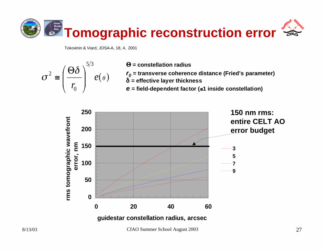
Tomographic reconstruction error
( )θδ
σ er
35
0
2
Θ≅
ΘΘΘΘ = constellation radius
r0 = transverse coherence distance (Fried’s parameter)δδδδ = effective layer thickness
e = field-dependent factor (≤≤≤≤1 inside constellation)
150 nm rms:entire CELT AOerror budget
0
50
100
150
200
250
0 20 40 60
guidestar constellation radius, arcsec
rms
to
mo
gra
ph
ic w
av
efr
on
t e
rro
r, n
m 3
579
Tokovinin & Viard, JOSA-A, 18, 4, 2001
8/13/03 CfAO Summer School August 2003 28
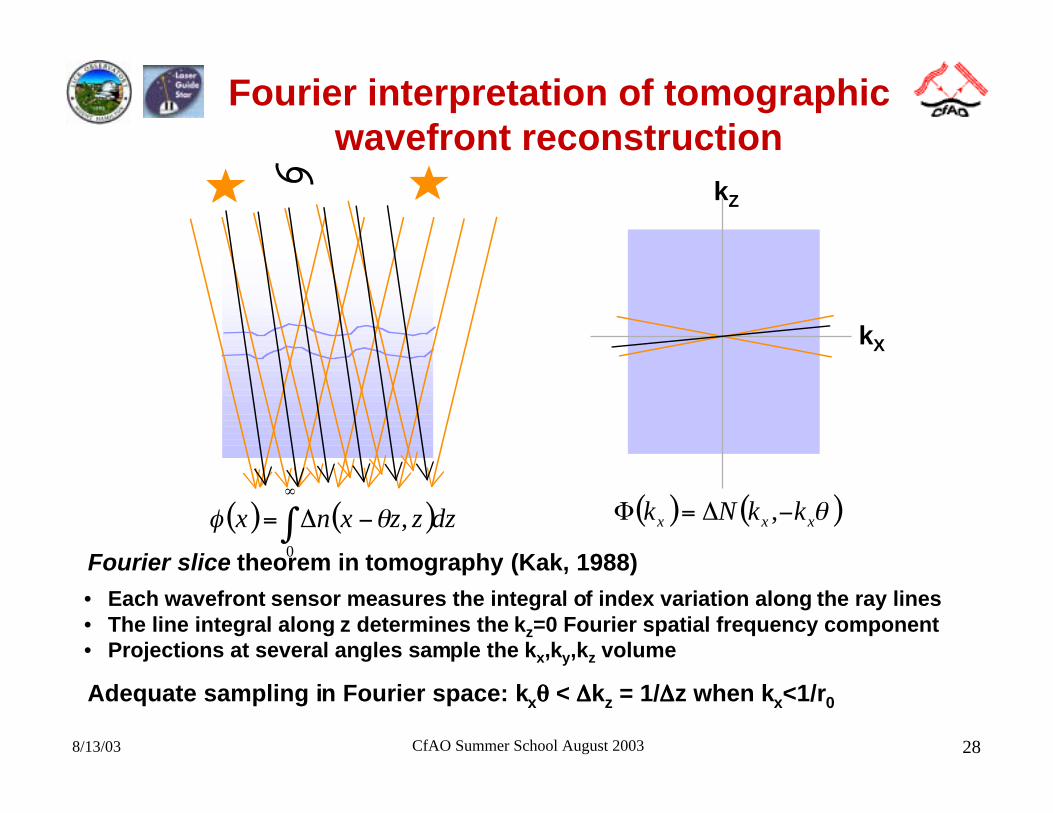
Fourier interpretation of tomographicwavefront reconstruction
• Each wavefront sensor measures the integral of index variation along the ray lines• The line integral along z determines the kz=0 Fourier spatial frequency component• Projections at several angles sample the kx,ky,kz volume
kX
kZ
( ) ( )∫∞
−∆=0
, dzzzxnx θφ ( ) ( )θxxx kkNk −∆=Φ ,
Fourier slice theorem in tomography (Kak, 1988)
Adequate sampling in Fourier space: kxθθθθ < ∆∆∆∆kz = 1/∆∆∆∆z when kx<1/r0
8/13/03 CfAO Summer School August 2003 29
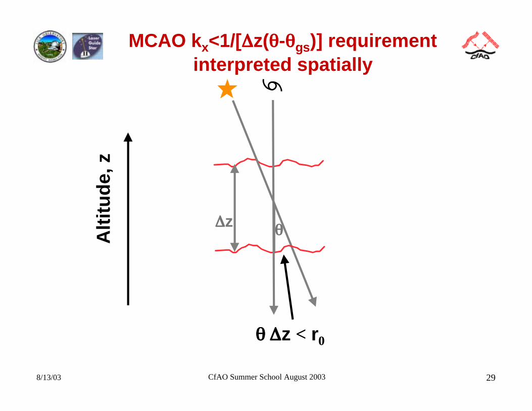
MCAO kx<1/[∆∆∆∆z(θθθθ-θθθθgs)] requirementinterpreted spatially
θθθθ∆∆∆∆z
θθθθ ∆∆∆∆z < r0
Alt
itu
de,
z
8/13/03 CfAO Summer School August 2003 30
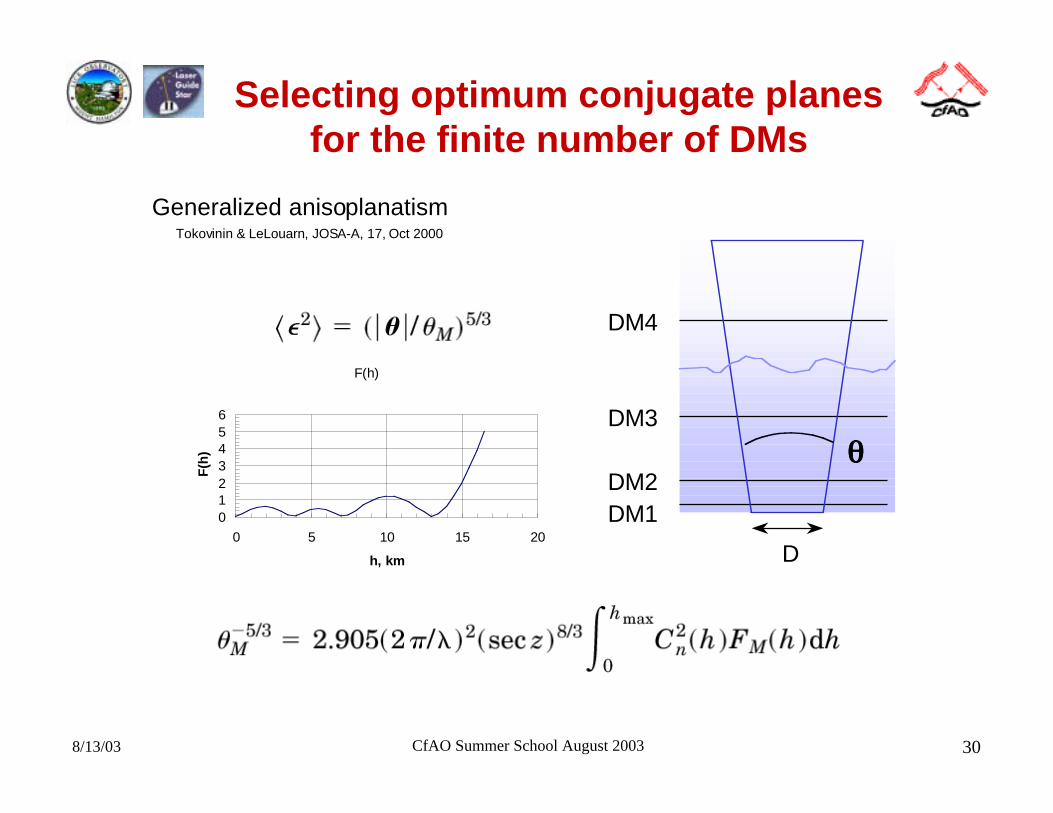
Selecting optimum conjugate planesfor the finite number of DMs
DM4
DM3
DM2DM1
D
θθθθ
Tokovinin & LeLouarn, JOSA-A, 17, Oct 2000
Generalized anisoplanatism
F(h)
0123456
0 5 10 15 20
h, km
F(h
)
8/13/03 CfAO Summer School August 2003 31
MCAO fitting error
• Problem:– We have chosen the total number of DMs and their multi-conjugate
locations using the previous techniques so as to minimize anisoplanatism– Now, how many actuators do we need per DM to achieve adequate fitting
of the wavefront at each altitude?
• Solution Approach:– Pick an error budget for the fitting error
– Pick a total number of actuators– Distribute the actuators “parato-optimally” - I.e. so that total fitting error is
not improved by taking an actuator from one DM and putting on another– Adjust the total number of actuators and repeat until the specified total
fitting error is achieved
– This approach solves a dual problem• Minimum number of actuators to achieve a given fitting error• Minimum fitting error with a given number of actuators
8/13/03 CfAO Summer School August 2003 32
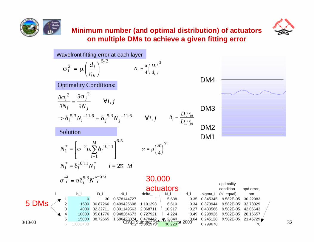
Minimum number (and optimal distribution) of actuatorson multiple DMs to achieve a given fitting error
σ µii
i
dr
2
0
5 3
=
Optimality Conditions:
∂σ∂
∂σ
∂
δ δ
i
i
j
j
i i j j
N Ni j
N N i j
2 2
5 3 11 6 5 3 11 6
= ∀
⇒ = ∀− −
,
,
NDdi
i
i=
π4
2
α µπ
=
4
5 6
DM4
DM3
DM2DM1
i h_i D_i r0_i delta_i N_i d_i sigma_i
optimality condition (all equal)
opd error, nm
1 0 30 0.578144727 1 5,638 0.35 0.345345 9.582E-05 30.229832 1500 30.87266 0.499425698 1.191293 6,610 0.34 0.373944 9.582E-05 32.733293 4000 32.32711 0.301149563 2.068711 10,917 0.27 0.480566 9.582E-05 42.066434 10000 35.81776 0.948264673 0.727921 4,224 0.49 0.298926 9.582E-05 26.166575 15000 38.72665 1.586423374 0.470442 2,840 0.64 0.245128 9.582E-05 21.457295 1.00E+08 0.2 5.361973 30,228 0.799678 70
Solution
N
N N i M
N
ii
M
i i
i i i
12 10 11
1
6 5
10 111
2 5 3 5 6
2
*
* *
* *
=
= =
=
−
=
−
∑σ α δ
δ
σ αδ
K
Wavefront fitting error at each layer
5 DMs
30,000actuators
δ ii iD r
D r= 0
1 01
8/13/03 CfAO Summer School August 2003 33
Specific AO designs
• Lick laser guidestar system
• Keck laser guidestar system
• CELT MCAO multi-laser guidestar system
8/13/03 CfAO Summer School August 2003 34
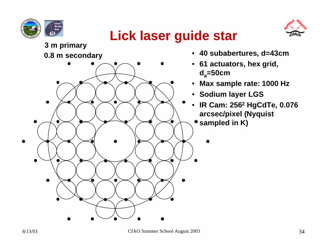
Lick laser guide star3 m primary0.8 m secondary • 40 subabertures, d=43cm
• 61 actuators, hex grid,da=50cm
• Max sample rate: 1000 Hz• Sodium layer LGS• IR Cam: 2562 HgCdTe, 0.076
arcsec/pixel (Nyquistsampled in K)
8/13/03 CfAO Summer School August 2003 35
Keck laser guide star
• 10 meter equivalent area telescope aperture
• 349 Actuator DM (rectangular grid)• 50 cm subapertures
• 20 watt laser beacon– Sodium dye laser– Projected from the side of the telescope (spot elongation)
• Science camera (NIRC-II) Nyquist sampled in H (λ=1.6µ)
8/13/03 CfAO Summer School August 2003 36
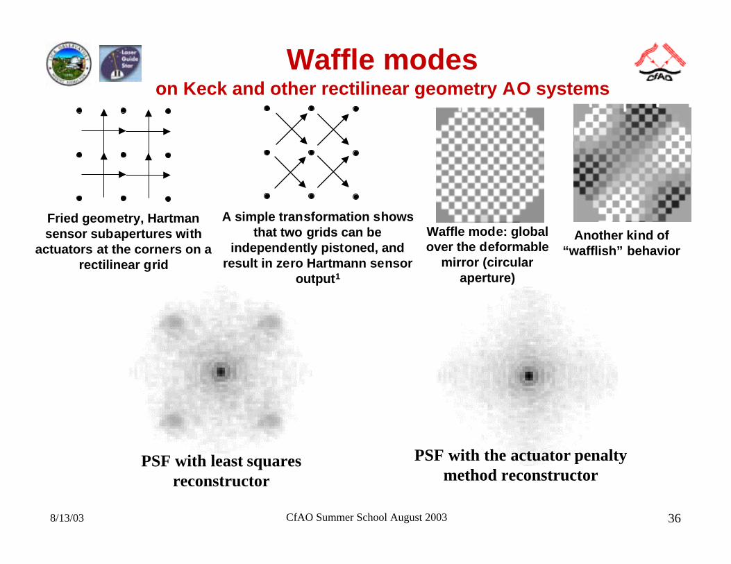
Waffle modeson Keck and other rectilinear geometry AO systems
PSF with least squaresreconstructor
PSF with the actuator penaltymethod reconstructor
Fried geometry, Hartmansensor subapertures with
actuators at the corners on arectilinear grid
A simple transformation showsthat two grids can be
independently pistoned, andresult in zero Hartmann sensor
output1
Waffle mode: globalover the deformable
mirror (circularaperture)
Another kind of“wafflish” behavior
8/13/03 CfAO Summer School August 2003 37
CELT MCAO
• Requirements– 30 Meter aperture concept (Future Giant Telescope)
– Needs multiple laser guidestars just to overcome cone effect– 2 arcminute field of view desired– Strehl of 0.5 at λ=1µ desired (113 nm error budget)
• Design Concept– 4 conjugate DMs, 20-30 thousand total actuators
– 7 sodium laser guidestars in a configurable constellation– 7 wavefront sensors in the tomographic reconstruction
configuration– Sodium LGS spot size mitigation
– Several NGS tip/tilt sensors - to break LGS ambiguous modes -these will be IR detectors to take advantage of AO correction ofdimmer stars to allow higher sky coverage
8/13/03 CfAO Summer School August 2003 38
Summary
• Building an adaptive optics system is a complicatedmultidisciplinary project. Adequate reviews at critical phases ofthe design process are important.
• AO wavefront correction systems for a wide variety ofapplications have many of the same design considerations.
• Multi conjugate adaptive optics is very similar in concept totomography.
• A concept for a 30 meter telescope AO system is in the initialstudy phase