Embed Size (px)
Citation preview

Improved Performance of Adaptive Hysteresis Current Controller Based Vector Control of PMSM
Drive System
Amiya Naik, B.Chitti Babu, and A.K.Panda Department of Electrical Engineering, National Institute of Technology, Rourkela
E-mail: [email protected]
Abstract— The conventional hysteresis current controller has proved that, it is most suitable for current regulated VSI fed ac drives due to its ease of implementation and fast current tracking. However, it has certain limitations like large current ripple in steady state and variable switching frequency operation of IGBT inverter switch during motor load changes. This paper presents an adaptive hysteresis current controller in which the hysteresis band is programmed as a function of motor speed and load current. The proposed current control strategy is applied in the inner control loop of the vector controlled permanent magnet synchronous motor (PMSM) drive system in order to reduce the torque ripple during load variation and the obtained results are compared with conventional hysteresis controller under steady state and transient conditions with fixed and step changes in load. The complete PMSM drive system is modeled and tested in the MATLAB-Simulink environment for effectiveness of the study. Keywords-permanent magnet synchronous motor (PMSM); adaptive hysteresis controller; constant torque mode; vector control; modeling and simulation.
I. NOMENCLATURE B Friction co-efficient ia,ib,ic Three phase current id, iq d &q- axis stator current If Equivalent permanent magnet field current J Moment of Inertia Ld & Lq d & q-axis self inductance Ldm & Lqm d & q-axis magnetizing inductance Fc Cross-over frequency P No. of pole PI Proportional Integral controller Rs Stator resistance Te Electro magnetic torque Vd, Vq d & q-axis voltage ρ Derivative operator λd, λq d & q-axis flux linkage λf field flux linkage θr Rotor position ωm Rotor speed in rad/sec ωrated Motor rated speed in rad/sec
II. INTRODUCTION Along with the development of permanent magnet materials
and control technology, PMSM drive has gained an increasing popularity in low and medium power applications such as computer peripheral equipments, robotics, adjustable speed drives and electric vehicles are due to its following merits: high torque/inertia ratio, high power density and high efficiency etc [1][2].However, the dynamic performance of VSI fed PMSM drive system largely depends on the applied current control strategy. The main function of current controller is to force the load current to follow the reference current trajectory in order to minimize the current error [3][4].Variety of current control techniques has been proposed in the literature for adjustable speed ac drive system like induction motor drive and PMSM drive. L. Malesani et. all [5] has proposed hysteresis current controller in the inner loop of vector controlled PMSM drive system. We found though the hysteresis current controller provides good dynamic response and easy of implementation, it produces large current ripple under the steady state and variable switching operation of converter during load changes. B.K.Bose [3] has proposed adaptive hysteresis current controller for adjustable speed ac drive system in which the hysteresis band is programmed as a function of load current [6]. However the current controller performance is good during transient condition, it takes large computation time while the control algorithm is being implemented by micro controller or signal processors.
In this paper adaptive hysteresis current controller is proposed in the inner loop of vector control of PMSM drive system in which the hysteresis band is programmed a function of speed of the motor during load variations. Ultimately it reduces the large torque ripple during load variations, besides it takes less computation time for implementing using signal processors because of larger band width of inner loop. It acts faster for tracking the current during load variations. In addition to that, a closed loop control system with a PI controller in the outer speed loop has been designed to operate the drive in constant torque region. The obtained results are compared with conventional hysteresis controller under steady state and transient conditions with fixed and step change in the load. The proposed scheme is modeled and tested in the MATLAB-Simulink environment for effectiveness of the study.
978-1-4244-8942-8/11/$26.00 ©2011 IEEE

III. VECTOR CONTROL OF PMSM DRIVE SYSTEM
According to the classical theory of electrical machines, the
PMSM drive system is equivalent to that of the dc motor when a decoupling control is possible known as field oriented control (FOC) or vector control. The vector control decouples the torque component and flux producing current in the motor through its stator excitation by applying instantaneous space vector theory.
The vector control of the PM synchronous motor is derived from its dynamic d-q model [7]. Considering the currents as inputs, the three phase currents are given by
sina m ri I t (1)
2sin
3b m ri I t
(2)
2sin
3c m ri I t
(3)
Where δ is the angle between the rotor field and stator current phasor. The currents assigned above are the stator currents that must be transformed to the rotor reference frame with the rotor speed ωr, using Park’s transformation. The q and d axis currents are constants in the rotor reference frame since δ is a constant for a given load torque. As these are constants, they are similar to the armature and field currents in the separately excited dc machine. The q axis current is distinctly equivalent to the armature current (ia) and the d axis current is field current (if), but not in its entirety. It is only a partial field current; the other part is contributed by the equivalent current source representing the permanent magnet field. For this reason the q axis current is called the torque producing component of the stator current and the d axis current is called the flux producing component of the stator current. Solving by using park’s transformation, we get
sinq mi I (4)
cosd mi I (5)
From the above equations electromagnetic torque is obtained by
23 1. sin2 sin
2 2 2e d q m f m
PT L L I I
(6)
A. Constant Torque Operation
For vector control the knowledge of the position of the instantaneous rotor flux or rotor position of PMSM is needed. Knowing the position, the three phase currents can be calculated by using the current matrix depends on the applied
control strategy. Some control options are constant torque and flux weakening.
Constant torque control strategy is derived from field oriented control, where the maximum possible torque is desired at all times like the dc motor. This is performed by making the torque producing current iq equal to the supply current Im. That result in selecting the δ angle to be 90º degrees by making the id current equal to zero the torque equation can be rewritten as:
3.
2 2e f q
PT i
(7)
So,
.e t qT k i (8)
Where
3
2 2t f
Pk
From the equation (7) the torque of the motor can be controlled by controlling iq component of is.
IV. ANALYSIS OF ADAPTIVE HYSTERESIS CURRENT
CONTROLLER IN THE INNER LOOP Since the machine normally operating with isolated
neutral, this is the most practical case. Actually, with isolated neutral, the machine phase voltages interact and no longer be 0.5Vdc as with a connected neutral like as shown in fig.1.
Fig1. Adaptive Current controlled PMSM drive system
When Q1 is on , the possible phase-a voltage may be 0 , 1/3,
2/3Vdc , and when Q4 is on , the corresponding voltage may be 0 ,-1/3 , -2/3Vdc. Typical PWM phase voltage and current waves during a modulation cycle are shown in Fig.2. With the assumed polarity of counter emf when Q1 is on, the general
expression of incremental current rise HB during Q1 – on period is given by

*
1 1a a
n n
di diHB t t
dt dt
(9)
1adc f
diaV v
dt L
(10)
Fig.2.Typical PWM voltage and current waveform with Calculation of Hysteresis-band
Where a= 0, 1/3 or 2/3 & for simplicity let m=
*adi
dt
Hence 1 1
1n dc f nHB t aV v t m
L
(11)
Therefore, summing up the total current
1 1
1 1
12
1
f
n n dc
f
n dc
vHB HB t m t aV
L L
vt m t aV
L L
(12)
The general expression of incremental current fall during the Q4 – on period is given by
*
2 2a a
n n
di diHB t t
dt dt
(13)
But
1a
dc f
diaV v
dt L
(14)
Hence 22
ndc f n
tHB aV v t m
L
(15)
Therefore, the total fall is
2 2
2 2
12 ( )
1
f
n n dc
f
n dc
vHB HB t m t aV
L L
vt m t aV
L L
(16) t1 & t2 is the average current rise and fall duration respectively. In equation (12) and (16), the second term can be expressed as
1 1 'n dc dct aV t a V (17)
2 2 "n dc dct aV t a V (18)
or 1
1
' nt aa
t
(19)
2
2
" nt aa
t
(20) Where a' and a" are the respective applied voltage coefficients. Although the average applied voltages in the two intervals may have some asymmetry, still we assume a'= a" for computational simplicity. The parameters a' and a" will typically vary between 1/3 and 2/3. Adding equation (12) & (16) we get
1 2
'10 f dc
c
v a Vm t t
f L L
(21)
Where t1+t2=1/fc, fc is switching frequency
So, 1 2'
f
c dc
vLt t m
f a V L
(22) Now subtract equation (16) from (12)
2 1
'4 f dc
c
v a VHB m t t
L Lf
(23)
Putting the equation (22) in (23) and solving, we get 22
2 2
'0.25 1
'
fdc
c dc
va V LHB m
Lf a V L
(24)
From fig.3, which is showing phasor diagram of a PMSM the following equation can be written
sinf fm ev V (25)
Where 2fm f eV (26)
sin( )s sm eI I (27)
cos( )qs smI I (28)
sin( )ds smI I (29)
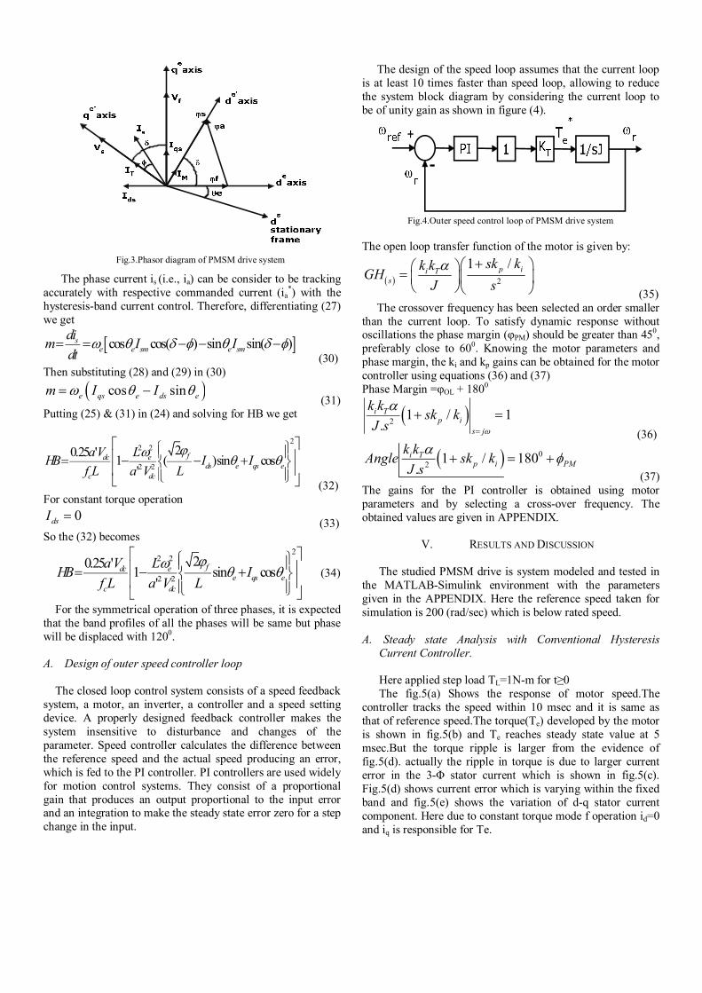
Fig.3.Phasor diagram of PMSM drive system
The phase current is (i.e., ia) can be consider to be tracking accurately with respective commanded current (ia
*) with the hysteresis-band current control. Therefore, differentiating (27) we get
cos cos( ) sin sin( )se e sm e sm
dim I I
dt
(30) Then substituting (28) and (29) in (30)
cos sine qs e ds em I I (31)
Putting (25) & (31) in (24) and solving for HB we get
22 2
2 2
20.25 '1 ( )sin cos
'
fdc eds e qs e
c dc
a V LHB I I
f L a V L
(32)
For constant torque operation
0dsI (33)
So the (32) becomes 2
2 2
2 2
20.25 '1 sin cos
'
fdc ee qs e
c dc
a V LHB I
f L a V L
(34)
For the symmetrical operation of three phases, it is expected that the band profiles of all the phases will be same but phase will be displaced with 1200.
A. Design of outer speed controller loop
The closed loop control system consists of a speed feedback
system, a motor, an inverter, a controller and a speed setting device. A properly designed feedback controller makes the system insensitive to disturbance and changes of the parameter. Speed controller calculates the difference between the reference speed and the actual speed producing an error, which is fed to the PI controller. PI controllers are used widely for motion control systems. They consist of a proportional gain that produces an output proportional to the input error and an integration to make the steady state error zero for a step change in the input.
The design of the speed loop assumes that the current loop is at least 10 times faster than speed loop, allowing to reduce the system block diagram by considering the current loop to be of unity gain as shown in figure (4).
-
+
Fig.4.Outer speed control loop of PMSM drive system
The open loop transfer function of the motor is given by:
2
1 /p ii Ts
sk kk kGH
J s
(35)
The crossover frequency has been selected an order smaller than the current loop. To satisfy dynamic response without oscillations the phase margin (φPM) should be greater than 450, preferably close to 600. Knowing the motor parameters and phase margin, the ki and kp gains can be obtained for the motor controller using equations (36) and (37) Phase Margin =φOL + 1800
21 / 1
.i T
p i
s j
k ksk k
J s
(36)
0
21 / 180
.i T
p i PM
k kAngle sk k
J s
(37)
The gains for the PI controller is obtained using motor parameters and by selecting a cross-over frequency. The obtained values are given in APPENDIX.
V. RESULTS AND DISCUSSION The studied PMSM drive is system modeled and tested in
the MATLAB-Simulink environment with the parameters given in the APPENDIX. Here the reference speed taken for simulation is 200 (rad/sec) which is below rated speed.
A. Steady state Analysis with Conventional Hysteresis
Current Controller. Here applied step load TL=1N-m for t≥0 The fig.5(a) Shows the response of motor speed.The
controller tracks the speed within 10 msec and it is same as that of reference speed.The torque(Te) developed by the motor is shown in fig.5(b) and Te reaches steady state value at 5 msec.But the torque ripple is larger from the evidence of fig.5(d). actually the ripple in torque is due to larger current error in the 3-Φ stator current which is shown in fig.5(c). Fig.5(d) shows current error which is varying within the fixed band and fig.5(e) shows the variation of d-q stator current component. Here due to constant torque mode f operation id=0 and iq is responsible for Te.
0 0.02 0.04 0.06 0.08 0.1 0.12
0
100
200
Spee
d(rad
/sec)
0 0.02 0.04 0.06 0.08 0.1 0.120
2
4
6
Te(N
-m)
0 0.02 0.04 0.06 0.08 0.1 0.12-10
0
10
Iabc
(A)
0 0.02 0.04 0.06 0.08 0.1 0.12-1
0
1
Erro
r(A)
0 0.02 0.04 0.06 0.08 0.1 0.12-10
0
10
Time(Sec)
Iqdo
(A)
Fig.5,(a)Response of speed;(b) Response of Te; (c) Stator current waveform;(d) Current error;(e) d-q components of stator current.
-0.4 -0.2 0 0.2 0.4 0.6
-0.4
-0.2
0
0.2
0.4
0.6
x-y plot of stator flux
Fig.6.Response of stator flux during steady state conditions
This fig. 6 shows the variation of stator flux in x-y plot contains large ripples due to fixed band.
B. Steady state Analysis with Adaptive Hysteresis Current
Controller. As shown in fig.7 (a) shows the speed of the motor which
reaches the steady state 10 msec. The torque Te developed by PMSM drives is shown in fig.7 (b). It reveals that, almost entire torque ripple is minimized by the action of adaptive hysteresis current controller. The corresponding stator current waveforms and current error is shown in fig. 7 (c) and (d). Fig.7 (e) shows the d-q components of stator current.
Fig.8 (b).shows x-y plot of stator flux which is almost ripple free due to adaptive-band of adaptive hysteresis current controller which is depicted by fig.8 (a).
0 0.02 0.04 0.06 0.08 0.1 0.12
0
100
200
Spee
d(ra
d/se
c)
0 0.02 0.04 0.06 0.08 0.1 0.120
2
4
6
Te(N
-m)
0 0.02 0.04 0.06 0.08 0.1 0.12-10
0
10
Iabc
(A)
0 0.02 0.04 0.06 0.08 0.1 0.12-1
0
1
Erro
r(A
)
0 0.02 0.04 0.06 0.08 0.1 0.12-10
0
10
Time(Sec)Iq
do(A
)
Fig.7,(a)Response of speed;(b) Response of Te; (c) Stator current waveform;(d) Current error;(e) d-q components of stator current.
0 0.02 0.04 0.06 0.08 0.1 0.12-0.02
0
0.02
0.04
0.06
0.08
Time(sec)
Ban
d(A
)
Fig.8. (a) Adaptive band
-0.4 -0.2 0 0.2 0.4 0.6
-0.4
-0.2
0
0.2
0.4
0.6
x-y plot of stator flux
Fig.8 (b).Response of stator flux during steady state conditions
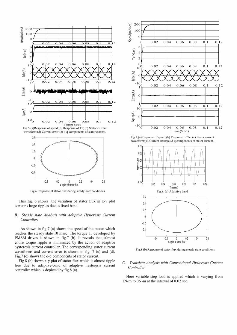
C. Transient Analysis with Conventional Hysteresis Current Controller
Here variable step load is applied which is varying from
1N-m to 0N-m at the interval of 0.02 sec.
0 0.02 0.04 0.06 0.08 0.1 0.12
0
100
200
Spee
d(ra
d/se
c)
0 0.02 0.04 0.06 0.08 0.1 0.120
2
4
6
Te(N
-m)
0 0.02 0.04 0.06 0.08 0.1 0.12-10
0
10
Iabc
(A)
0 0.02 0.04 0.06 0.08 0.1 0.12-1
0
1
Erro
r(A)
0 0.02 0.04 0.06 0.08 0.1 0.12-10
0
10
Time(Sec)
Iqdo
(A)
Fig.9,(a)Response of speed;(b) Response of Te; (c) Stator current waveform;(d) Current error;(e) d-q components of stator current.
Fig.9 (a) shows the response of motor speed which tracks the reference speed at 10 msec and it maintains constant irrespective of load variation by the action of PI controller in the outer loop of PMSM drive system. Fig.9 (b) shows the response of electromagnetic torque Te during transient condition. In this case the steady state is reached within 10 msec and torque ripple is quite larger due to load changes. The corresponding stator current and current error is shown in fig. Fig.9 (c) and Fig.9 (d). Fig.9 (e) shows the variation of d-q components of stator current.
-0.4 -0.2 0 0.2 0.4 0.6
-0.4
-0.2
0
0.2
0.4
0.6
x-y plot of stator flux
Fig.10.Response of stator flux during transient conditions
The fig.10 shows the variation of stator flux in x-y plot. During the transient period of load variation the stator flux is attaining steady state at faster rate.
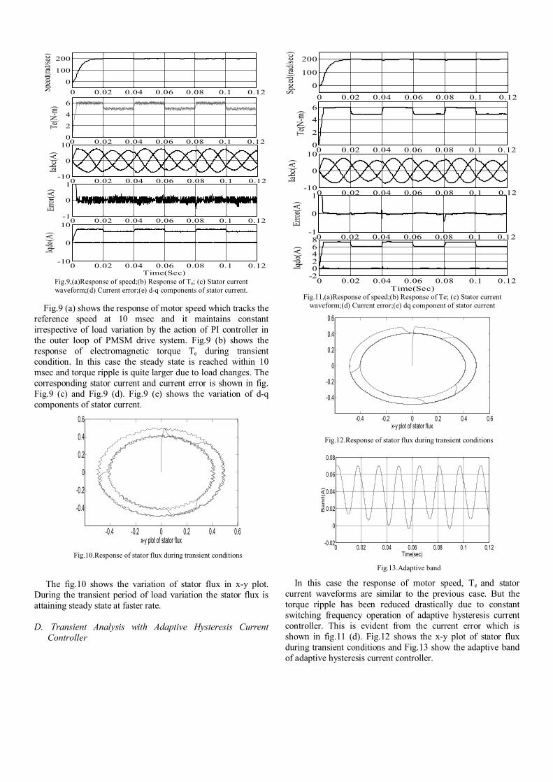
D. Transient Analysis with Adaptive Hysteresis Current
Controller
0 0.02 0.04 0.06 0.08 0.1 0.12
0
100
200
Spee
d(ra
d/se
c)
0 0.02 0.04 0.06 0.08 0.1 0.120
2
4
6
Te(N
-m)
0 0.02 0.04 0.06 0.08 0.1 0.12-10
0
10
Iabc
(A)
0 0.02 0.04 0.06 0.08 0.1 0.12-1
0
1
Erro
r(A)
0 0.02 0.04 0.06 0.08 0.1 0.12-202468
Time(Sec)Iq
do(A
)
Fig.11,(a)Response of speed;(b) Response of Te; (c) Stator current waveform;(d) Current error;(e) dq component of stator current
-0.4 -0.2 0 0.2 0.4 0.6
-0.4
-0.2
0
0.2
0.4
0.6
x-y plot of stator flux
Fig.12.Response of stator flux during transient conditions
0 0.02 0.04 0.06 0.08 0.1 0.12-0.02
0
0.02
0.04
0.06
0.08
Time(sec)
Ba
nd
(A
)
Fig.13.Adaptive band
In this case the response of motor speed, Te and stator current waveforms are similar to the previous case. But the torque ripple has been reduced drastically due to constant switching frequency operation of adaptive hysteresis current controller. This is evident from the current error which is shown in fig.11 (d). Fig.12 shows the x-y plot of stator flux during transient conditions and Fig.13 show the adaptive band of adaptive hysteresis current controller.

E. Comparison Analysis
The current tracking performance of both conventional and adaptive hysteresis current controller are shown in fig.14 and 15 respectively. Due to variable switching frequency operation of hysteresis current controller, stator current ripple is more. But the current error is entirely minimized by the action of proposed adaptive hysteresis current controller and the stator current almost same as that of reference current commend. This is because of variable hysteresis band during load current changes.
0.03 0.035 0.04 0.045 0.05 0.055 0.06-8
-6
-4
-2
0
2
4
6
8
Time(Sec)
Cur
rent
(A)
Ia*IaIea
Fig.14.Current control action by hysteresis current controller
0.03 0.035 0.04 0.045 0.05 0.055 0.06-8
-6
-4
-2
0
2
4
6
8
Time(Sec)
Cur
rent
(A)
Ia*
IaIea
Fig.15 Current control action by adaptive hysteresis
current controller
Fig.16 Variation of average switching frequency with load.
From fig.16 we observed that, the switching frequency is varying nearly about 2 kHz during variation of load in conventional hysteresis current controller, but it is nearly constant for adaptive hysteresis current controller irrespective of load variations.
VI. CONCLUSION
In this paper, the performance improvement of vector
controlled PMSM drive system has been studied by employing adaptive hysteresis current controller in the inner current control loop. From the study we observed that, during
transient conditions adaptive hysteresis current controller largely reduces the torque ripple in turn; it can provide smooth running of PMSM drive system during low speed operation when compared to classical hysteresis current controller. In addition, we found that the adaptive hysteresis current controller can enable to track the load current with reference current at a faster rate in order to improve the dynamic response of the system and it takes less computation time while it will be practically implemented in the digital processor platform.
REFERENCES
[1] P. Pillay and R. Krishnan, "Modeling of permanent magnet motor
drives," IEEE Trans., on Ind. Electron. , vol. 35, pp. 537-541, 1988. [2] P. Pillay and R. Krishnan, "Modeling, simulation, and analysis of
permanent-magnet motor drives." IEEE Trans., on Ind. Appl., vol. 25, pp. 265-273, 1989.
[3] B. k. Bose, "An adaptive hysteresis-band current control technique of a voltage - fed PWM inverter for machine drive system", IEEE Trans., on Ind. Appl., Vol.IA-37, pp.402-408, 1990
[4] A. B. Plunkett, “A current controlled PWM transistor inverter drive,” in Proc. Conf. Rec. IEEE IAS Ann. Mtg., pp.785-792, 1979
[5] L. Malesani and P. Tenti, “A novel hysteresis control method for Current-controlled VSI PWM inverters with constant modulation frequency,” in Proc. Conf. Rec. IEEE IAS Ann. Mtg., pp.851-85, 1987
[6] Tae-Won Chun; Meong-Kyu Choi;” Development of adaptive hysteresis band current control strategy of PWM inverter with constant switching frequency“Applied power electronics conf. and exposition, APEC. vol.1,pp.194-199, 1996
[7] B. Cui, J. Zhou, and Z. Ren, "Modeling and simulation of permanent magnet synchronous motor drives," Electrical machines and system,.ICEMS, vol.2, pp.905-908, 2001
[8] X. Jian-Xin, S. K. Panda, P. Ya-Jun, L. Tong Heng, and B. H. Lam, "A modular control scheme for PMSM speed control with pulsating torque minimization, “, IEEE Trans., on Ind. Electron., vol. 51, pp. 526-536, 2004.
[9] M.Kale, E.Ozdemir, “An adaptive hysteresis band current controller for shunt active power filters”, ELSEVIER Journal of Electric power systems research, 73, pp. 113-119, 2005.
[10] B. K. Bose, “Power Electronics and AC Drives. Prentice-Hall, 1986.
APPENDIX:
PMSM Drive system parameters for simulation
Rated voltage VLL 220 V Output power Pout 900 W No. of poles P 4 Rated Speed ωm 1700 rpm
Stator resistance RS 4.3 Ω PM flux linkage λaf 0.272Wb
d-axis Inductance Ld 27 mH q-axis Inductance Lq 67 mH
Rated current IS 3 A Maximum current ISMAX 2ISrated
Input voltage of inverter Vdc 300 V Motor inertia J 0.000179 kg m2
Damping coefficient B 0.05
Proportional constant kp 0.3581 Integral constant ki 129.9014
switching frequency fc 5kHz