Embed Size (px)
Citation preview
F force
i electrical current
m variable for neuro-fuzzy controller selection
N number of rules
Re Reynolds number
T temperature of the smart material actuator
Tamb ambient temperature
V speed
wi degree of fulfillment of the antecedent, i.e., the firing level
of the ith rule
x input vector
xq individual input variables (q = 1,2—
)
y output of the fuzzy model
y i first-order polynomial function in the consequent (i = 1,N—)
α angle-of-attack
σ dispersion
σ iq dispersion of the cluster
Δt time
Δδ elongation of the actuator
ABSTRACT
A neuro-fuzzy controller method for smart material actuator (SMA)hysteresis modelling is presented, conceived for a morphing wingapplication. The controller correlates each set of forces and electricalcurrents that are applied to the smart material actuators with theactuator elongation. The actuator is experimentally tested for fourforces, using a variable electrical current. The final controller isobtained through the Matlab/Simulink integration of threeindependent neuro-fuzzy controllers, designed for the increase anddecrease of electrical current, and for null electrical current in thecooling phase of the actuator. This final controller gives a very smallerror with respect to the experimental values.
NOMENCLATURE
Aiq associated individual antecedent fuzzy sets of each input
variable a i
k parameters of the linear function (k = 1,2—
, i = 1,N—)
bi0 scalar offset (i = 1,N—
)Cp pressure coefficientC i
q cluster centre
THE AERONAUTICAL JOURNAL JANUARY 2010 VOLUME 114 NO 1151 1
Paper No. 3410. Manuscript received 26 February 2009, revised 20 August 2009, accepted 2 September 2009.
New adaptive controller method for SMAhysteresis modelling of a morphing wing
T. L. Grigorie and R. M. Botez
Laboratory of Research in Active Controls, Avionics and AeroServoElasticity LARCASEÉcole de Technologie Supérieure, www.larcase.etsmtl.ca Montréal, Quebec Canada

effectiveness of the neural network open loop controller for trackingcontrol of the SMA wire actuator. A nonlinear control system for anSMA actuator using neural network based controllers was designed,and the experimental results showed that an SMA resistance controlwas possible(5). There are other approaches for controller modellingof SMA actuators, based on neural network and fuzzy logictechniques. The technique presented is a combination of both, andthus it is called the neuro-fuzzy method. The model is empirical,based on the numerical values resulting from the SMA’s experi-mental testing. It profits by the outstanding properties of fuzzy logic,which allows the empirical processing of the signals without mathe-matical analytical models. Another advantage of fuzzy logic is that itworks very well on nonlinear and multi-dimensional systems.
To elaborate the model, a fuzzy rules set and the membershipfunctions (mf) associated with each of the inputs are required(6,7).Obtaining a good fuzzy model depends on the ability and theexperience of the designer to consider the rules and the membershipfunctions of each of the inputs. However, a relatively new designmethod allows a competitive model to be built by using a combi-nation of fuzzy logic and neural-network techniques. Moreover, thismethod makes it possible to generate and to optimise the fuzzy rulesset and the parameters of the membership functions. Already imple-mented in Matlab(6,8), the method is easy to use, and gives very goodresults very quickly.
2.0 SMA EXPERIMENTAL TESTING
The SMA actuating system has the structure shown in Fig. 2. Eachsystem actuating line contains a cam, which moves in translationrelative to the structure (on the x-axis in Fig. 2); this cam causes themovement of the related rod on the roller and on the skin (on the z-axis). The recall is in the form of a compression spring. When theSMA is heated, the actuator contracts and the cam moves to the right,resulting in the upwards roller movement and in the upwards skindisplacement. On the contrary, SMA cooling results in a movement ofthe cam to the left, and thus into a downwards skin displacement.
As illustrated in Fig. 3, the SMA model’s aim is to achieveactuator elongation (Δδ) under the application of a thermo-electro-mechanical load over a certain period of time (Δt). The load’sactuator can be operated by varying the temperature (Tamb), byinjecting an electric current (i) or by application of a force (F). Theactuator geometry consists of an SMA wire with constant sectionarea and perimeter.
The SMA testing was performed at Tamb = 24°C using the benchtest shown in Fig. 4, for four load cases of values 60N, 110N, 160Nand 205N. During these tests, electrical current was supplied by useof a zero-increasing-decreasing-zero cycle for each of these fourload cases. The following parameters were recorded: the time, theSMA supplying electrical current, the load force, the materialtemperature and the actuator elongation (which was measured usinga linear variable differential transformer LVDT).
1.0 INTRODUCTION
The continuous need to reduce fuel consumption and other directoperating costs for new aircraft has spurred significant researchefforts in the morphing wing area. These technologies will enableaircraft to be more efficient and operate under a wide range ofvarying flight conditions. Also, the morphing technologies will beused to improve aircraft performance, expand the flight envelope,replace conventional control surfaces, reduce drag and thus improverange, and reduce vibrations and flutter(1).
Multidisciplinary morphing wing research projects involveextremely complex interactions between controls, aerodynamics,structures, actuator power requirements, sensor integrations and allof the other components(2).
Within this context, our team has included wind tunnel simula-tions and experimental multidisciplinary studies for a morphingwing equipped with a flexible skin, smart material actuators (SMAs)and optical sensors. The aim of these studies is to move thetransition point from the laminar to the turbulent regime closer to thetrailing edge by use of a controller in order to obtain a larger laminarflow region. This research project included the following: opticalsensor selection and testing for laminar-to-turbulent flow transitionvalidation (by use of XFoil code and Matlab), smart materialactuator controller methods, aeroelasticity wing studies usingMSC/Nastran, open loop and closed loop transition delay controllerdesign, integration and validation on a wing equipped with SMAsand optical sensors (simulation versus test results).
As shown in Fig. 1(3), a complex system was obtained, whichmodifies the aerofoil shape in order to optimise it from theperspective of the laminar flow region. For various flight conditions(angles-of-attack α, speeds V and Reynolds numbers Re), the loopcontroller would receive the aerofoil upper surface Cp distribution,determined from the surface pressure distribution measured by theoptical sensors. The Cp distribution is compared with a computa-tional fluid dynamics (CFD) database, which is generated so that fordifferent aerpfoil types, the transition point is given as a function ofthe Cp distribution. Once a match is found, a transition point isoffered to the loop controller by the CFD database; the controllerwill be able to decide if the aerofoil shape must be adjusted or not.The adjustment of the aerofoil shape is made in real time using theSMA actuators. The loop is closed by the aerofoil shape, whichoffers the optical sensors another surface pressure distribution.
In order to validate the morphing wing system (numericalsimulation versus test results), good numerical models for each ofthe physical elements in the system must be obtained. The aim ofthis paper is to offer a good model for SMA actuators, with directapplication to our morphing wing system.
Our goal is to build a neuro-fuzzy controller for SMA hysteresismodelling that is focused directly on our application. Other authorshave presented SMA modelling using Neural Network methods(4)
where the SMA actuator was controlled without using a positionsensor, and then the neural network inverse model was used as afeedforward controller. The experimental results demonstrated the
2 THE AERONAUTICAL JOURNAL JANUARY 2010
Figure 1. Closed-loop morphing wing system. Figure 2. Structure of the actuating system with SMAs.

remain one of the model outputs. The time values are very relevantfor this phase as they represent actuator thermal inertia measures.Therefore, time is the second input of the third controller, with forceas its first input (the time should be counted as starting when thecurrent becomes null).
In this study, the hysteresis cycles of elongation as a function oftemperature were shown. The ambient temperature, the electricalcurrents and the forces, experimentally obtained, were applied to theSMA model as inputs, with the elongation and the material temper-ature considered as outputs. The elongation curves as a function oftemperature for different load cases, and the 3D characteristics forthe experimental data in terms of temperature, elongation and forceare depicted in Fig. 5. A comparison between the elongation curvesobtained experimentally and those obtained with the new techniqueis presented in the next sections.
3.0 THE NEW APPROACH
A neuro-fuzzy network empirical model is devised based on thenumerical values from the SMA experimental testing. This modelcan learn the process behaviour, based on the input-output processdata, by using a fuzzy inference system (FIS) to model the experi-mental data. The experimental elongation-current curves obtained inthe four load cases considered here are represented in Fig. 6.
One can observe that each of these curves describes a hysteresiscycle, characterised by three distinct zones: electrical currentincrease, electrical current decrease and null electrical current in thecooling phase of the actuator. Therefore, three fuzzy inferencesystems FISs are used to obtain three neuro-fuzzy controllers: onefor the current increase, one for the current decrease, and one for thenull current (after its decrease).
For the first and for the second controller, the force and thecurrent inputs are used, while for the third controller, the force andthe time inputs are required for the SMA to recover its initialtemperature (of approximately 24°C). Finally, the three controllerswould be integrated into a single controller.
The design of the first two controllers is based on the availableexperimental data, in which two elongations are used for the samevalues of forces and currents (see Fig. 6). Due to the experimentaldata hysteresis, they cannot be represented as algebraic functions.Therefore, it is impossible to use data in the same FIS representationbecause an interpolation between the two elongation values isobtained for the same values of forces and currents. On the otherhand, the null current values following the current decrease phaseshould not be considered as inputs in the third controller, becausethey are not suggestive. During this phase, for practical reasons, theactuator temperatures should be used instead, but temperature should
GRIGORIE AND BOTEZ NEW ADAPTIVE CONTROLLER METHOD FOR SMA HYSTERESIS MODELLING OF A MORPHING WING 3
Figure 3. The SMA model input/output structure.
Figure 4. The SMA bench test.
Figure 5. Experimental data evaluation.
Figure 6. Elongation versus the current values for four forces.

wi (x) represents the degree of fulfillment of the antecedent, that is,the level of firing of the ith rule.
The Matlab ‘genfis2’ function generates Gaussian typemembership functions, defined as follows(7), (10):
where ciq is the cluster centre and σ i
q is its dispersion.The FIS’s training is achieved with the Matlab ‘ANFIS’ function,
which uses a learning algorithm for the identification of themembership functions’ Sugeno-type FIS parameters with twooutputs and one input. As a starting point, the input-output data andthe FIS model generated with the ‘genfis2’ function are considered.Matlab’s ‘ANFIS’ optimises the membership functions’ (mf)parameters for a given number of training epochs; a number set bythe user. This optimisation is realised so that a better process approx-imation can be performed by the neuro-fuzzy model thanks to aquality parameter in the training algorithm(8). Following the training,the models may be used for elongation value generation corre-sponding to the input parameters.
After the three controllers (Controller 1 for increasing current,Controller 2 for decreasing current and Controller 3 for null current)have been obtained, they should be integrated. This scheme is shownin Fig. 7. The decision to use one of the three controllers depends onthe current vector type (increasing (I(j) > I(j – 1)), decreasing (I(j) <I(j – 1)), constant (I(j) = I(j – 1)) or zero(I(j) = 0)) and on the ‘m’variable value. This ‘m’ value determines if a constant current valueis part of an increasing vector or part of a decreasing vector. Theinitial ‘m’ value is equal to 1 when Controller 1 is used, and is equalto 0 when Controller 2 or Controller 3 is used.
It is also possible to create fuzzy inference systems (FISs) usingthe Matlab ‘genfis2’ function, which generates an initial Sugeno-type FIS by decomposition of the operation domain into differentregions using the fuzzy subtractive clustering method. For eachregion, the local process parameters could be described with a loworder linear model. The non-linear process is thereby linearisedlocally around a functioning point by using the least squares method.The obtained model is then considered valid in the entire regionaround this point. The limitations of the operating regions imply theexistence of overlapping among these different regions; their defin-ition is given in a fuzzy manner.
Thus, for each model input, several fuzzy sets are associated withtheir membership function (mf) definitions. By combining thesefuzzy inputs, the input space is divided into fuzzy regions. For eachsuch region, a local linear model is used, while a global model isobtained by defuzzification with the gravity centre method (Sugeno),through which the interpolation of the local models’ outputs isrealised(6, 8).
The Sugeno fuzzy model was proposed by Takagi, Sugeno andKang to generate fuzzy rules from a given input-output data set(9).For our system, and for all the three FISs (two inputs and oneoutput), a first-order model was considered; the description of the Nrules is given as Refs 9 and 10:
Rule 1: If x1 is A11 and x2 is A1
2, then y1(x1,x2) = b10 + a1
1x1 + a12x2,
Rule i: If x1 is A1i and x2 is Ai
2, then yi(x1,x2) = b i0 + a1
1x1 + ai2x2, . . . (1)
Rule N: If x1 is A1N and x2 is AN
2, then yN(x1,x2) = bN0 + aN
1x1 + aN2x2,
where xq(q = 1,2—
) are the individual input variables, Aiq(i = 1,N—
) arethe associated individual antecedent fuzzy sets of each input variableand y i(i = 1,N—
) is the first-order polynomial function in the conse-quent. In addition, a i
k(k = 1,2—
, i = 1,N—) contains the linear function
parameters and bi0(i = 1,N—
) denotes a scalar offset. The parameters a ik
,bi0(k = 1,2
—, i = 1,N—
) bi0 (i = 1,N—
) are optimised by use of the leastsquare method.
For any input vector x = [x1, x2]T, in the case with a singleton
fuzzifier, the product fuzzy inference and the centre-averagedefuzzifier are applied and the fuzzy model output y is inferred asfollows (weighted average):
where
4 THE AERONAUTICAL JOURNAL JANUARY 2010
. . . (2)
. . . (3)
. . . (4)
Figure 7. Logical scheme for the three controller’s integration.
Figure 8. The structure of ‘ElongationFis’ FIS.
Figure 9. The structure of Controller 1.
4.0 THE CONTROLLER DESIGN AND
EVALUATION
The ‘genfis2’ Matlab function(8) was used to build and train thefollowing three fuzzy inference systems: ‘ElongationFis’ (for thecurrent increase phase), ‘dElongationFis’ (for the current decreasephase), and ‘d0ElongationFis’ (for the null current values obtainedafter the decrease phase). The three FISs were trained for differenttraining epochs and the best results were obtained for 250,000epochs.
For the system presented here, a set of eight rules are obtained for‘ElongationFis’, seven for ‘dElongationFis’ and ten for‘d0ElongationFis’. These rules are of the following types: if (in1 isin1cluster‘k’) and (in2 is in 2 cluster‘k’) then (out1 is out1cluster‘k’).The number of rules is generated automatically by the ‘genfis2’Matlab function starting from the experimental data set.
For each of the two FIS’s inputs, 8, 7 and 10 Gaussian-typemembership functions (mf) were generated, respectively; within this setof rules, these mf are denoted by: in‘j’ cluster‘k’; j is the input number(j = 1 or 2 for all of the three FISs), and k is the number of membershipfunctions (k = 1÷8 for ‘ElongationFis’, k = 1÷7 for ‘dElongationFis’,and k = 1÷10 for ‘d0ElongationFis’). For example, the ‘ElongationFis’FIS has the structure shown in Fig. 8, while its corresponding controller(Controller 1) has the structure shown in Fig. 9.
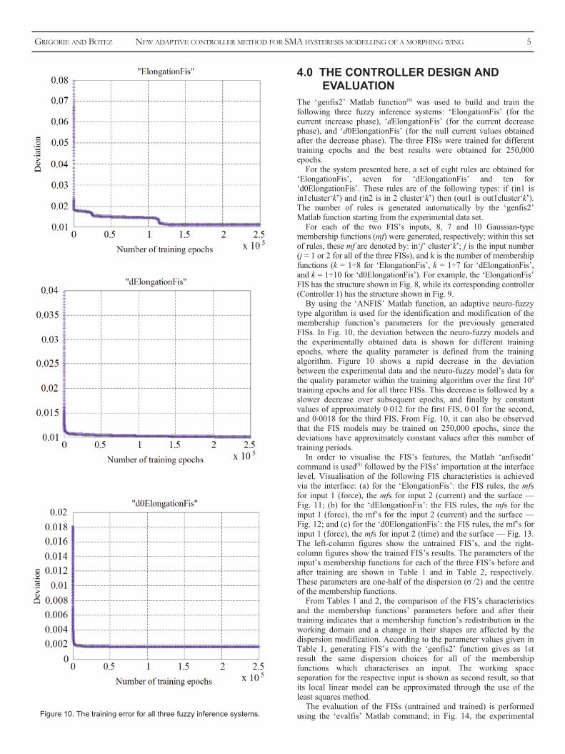
By using the ‘ANFIS’ Matlab function, an adaptive neuro-fuzzytype algorithm is used for the identification and modification of themembership function’s parameters for the previously generatedFISs. In Fig. 10, the deviation between the neuro-fuzzy models andthe experimentally obtained data is shown for different trainingepochs, where the quality parameter is defined from the trainingalgorithm. Figure 10 shows a rapid decrease in the deviationbetween the experimental data and the neuro-fuzzy model’s data forthe quality parameter within the training algorithm over the first 104
training epochs and for all three FISs. This decrease is followed by aslower decrease over subsequent epochs, and finally by constantvalues of approximately 0.012 for the first FIS, 0.01 for the second,and 0.0018 for the third FIS. From Fig. 10, it can also be observedthat the FIS models may be trained on 250,000 epochs, since thedeviations have approximately constant values after this number oftraining periods.
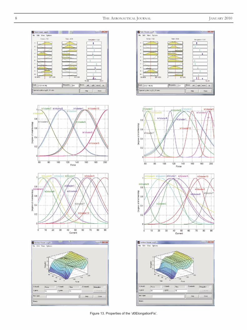
In order to visualise the FIS’s features, the Matlab ‘anfisedit’command is used(8) followed by the FISs’ importation at the interfacelevel. Visualisation of the following FIS characteristics is achievedvia the interface: (a) for the ‘ElongationFis’: the FIS rules, the mfsfor input 1 (force), the mfs for input 2 (current) and the surface —Fig. 11; (b) for the ‘dElongationFis’: the FIS rules, the mfs for theinput 1 (force), the mf’s for the input 2 (current) and the surface —Fig. 12; and (c) for the ‘d0ElongationFis’: the FIS rules, the mf’s forinput 1 (force), the mfs for input 2 (time) and the surface — Fig. 13.The left-column figures show the untrained FIS’s, and the right-column figures show the trained FIS’s results. The parameters of theinput’s membership functions for each of the three FIS’s before andafter training are shown in Table 1 and in Table 2, respectively.These parameters are one-half of the dispersion (σ /2) and the centreof the membership functions.
From Tables 1 and 2, the comparison of the FIS’s characteristicsand the membership functions’ parameters before and after theirtraining indicates that a membership function’s redistribution in theworking domain and a change in their shapes are affected by thedispersion modification. According to the parameter values given inTable 1, generating FIS’s with the ‘genfis2’ function gives as 1stresult the same dispersion choices for all of the membershipfunctions which characterises an input. The working spaceseparation for the respective input is shown as second result, so thatits local linear model can be approximated through the use of theleast squares method.
The evaluation of the FISs (untrained and trained) is performedusing the ‘evalfis’ Matlab command; in Fig. 14, the experimental
GRIGORIE AND BOTEZ NEW ADAPTIVE CONTROLLER METHOD FOR SMA HYSTERESIS MODELLING OF A MORPHING WING 5
Figure 10. The training error for all three fuzzy inference systems.

6 THE AERONAUTICAL JOURNAL JANUARY 2010
Figure 11. Properties of the ‘ElongationFis’.

GRIGORIE AND BOTEZ NEW ADAPTIVE CONTROLLER METHOD FOR SMA HYSTERESIS MODELLING OF A MORPHING WING 7
Figure 12. Properties of the ‘dElongationFis’.
8 THE AERONAUTICAL JOURNAL JANUARY 2010
Figure 13. Properties of the ‘d0ElongationFis’.

scheme shown in Fig. 7; the Matlab/Simulink model is obtained asshown in Fig. 16.
In the Matlab/Simulink model, the second input of Controller 3(Time) is generated by using an integrator, and starts at the timewhen Controller 3 is used. Since it is possible that the simulationsample time may be different than the sample time used in the exper-imental data acquisition process, the ‘Gain’ block giving their ratiowas used; ‘Te’ is the sample time in the experimental data and “T” isthe simulation sample time. The ‘C’ constant represents themaximum time considered for the actuator to recover its initialtemperature when the current becomes null (approximately 24oC).
Evaluating the integrated controller model (see Fig. 16) for allfour of the experimental data cases produces the results shown inFig. 17. These results are represented in the form of elongationsversus temperature using the experimental data and the neuro-fuzzycontroller model for the SMA hysteresis. The curves show that thereis a good overlap between the neuro-fuzzy integrated controlleroutputs and the experimental data.
The same conclusions are obtained from the 3D characteristics ofthe experimental data and for the neuro-fuzzy modelled data in termsof temperature, elongation, and force, depicted in Fig. 18.
The mean absolute relative errors of the neuro-fuzzy controllerversus the experimental data have the following values: 4.15% and0.64% for a neuro-fuzzy controller with untrained and trained FISs,respectively.
data and their corresponding FIS models are shown for untrained(left-column figures) and trained (right-column figures) FISs. Figure14 reveals the same observations as those shown in Fig. 10. Note theoverlapping of the FIS models with their experimental elongationdata. This superposition is dependent on the training epochs’number, so that it is much better when the training epochs’ numberis higher. In other words, an improved real model approximation canbe achieved with the neuro-fuzzy methods when a higher experi-mental data number is used.
Representations of the elongations (both those obtained experi-mentally and from using the three FIS models) expressed asfunctions of the electrical current for the first two FISs, and as afunction of time for the third, are shown in Fig. 15. The curves forall four SMA load cases are represented, before and after the FIS’straining (left- and right-column figures). One can easily observe thatwith training, the FIS’s data model fits the experimental data verywell, and that the SMA has different thermal constants, dependingon the force values.
The mean absolute relative errors between the experimental dataand the FIS models for untrained and for trained FISs are given inTable 3.
Starting from the three obtained FISs, three controllers aregenerated: Controller 1 (‘ElongationFis’), Controller 2(‘dElongationFis’) and Controller 3 (‘d0ElongationFis’). Theintegration of these three controllers is realised by using the logical
GRIGORIE AND BOTEZ NEW ADAPTIVE CONTROLLER METHOD FOR SMA HYSTERESIS MODELLING OF A MORPHING WING 9
Table 1Parameters of the input’s FIS membership functions before training
ElongationFis dElongationFis dElongationFis
Force [N] Current [A] Force [N] Current [A] Force [N] Time [s]
σ/2 Centre σ/2 Centre σ/2 Centre σ/2 Centre σ/2 Centre σ/2 Centre
mf1 26.32 109.5 0.9413 1.65 26.75 109.5 0.9413 3.038 26.55 155.4 16.57 50.11mf2 26.32 107.2 0.9413 4.05 26.75 109.4 0.9413 0.975 26.55 60.07 16.57 43.68mf3 26.32 205.7 0.9413 1.725 26.75 203.7 0.9413 3.15 26.55 207 16.57 67.04mf4 26.32 60.17 0.9413 1.575 26.75 59.86 0.9413 1.65 26.55 108.7 16.57 21.53mf5 26.32 157.7 0.9413 3.225 26.75 60.55 0.9413 4.35 26.55 206.3 16.57 19.81mf6 26.32 60.77 0.9413 4.425 26.75 205.2 0.9413 0.975 26.55 59.66 16.57 9.794mf7 26.32 156.3 0.9413 0.375 26.75 157.3 0.9413 4.275 26.55 60.05 16.57 77.72mf8 26.32 206.9 0.9413 4.35 - - - - 26.55 107.2 16.57 64.59mf9 - - - - - - - - 26.55 156.9 16.57 4.837mf10 - - - - - - - - 26.55 159.1 16.57 89.18
Table 2 Parameters of the input’s FIS membership functions after training
ElongationFis dElongationFis d0ElongationFis
Force [N] Current [A] Force [N] Current [A] Force [N] Time [s]
σ/2 Centre σ/2 Centre σ/2 Centre σ/2 Centre σ/2 Centre σ/2 Centre
mf1 26.01 109.1 0.6943 2.577 26.88 109.8 1.013 2.175 35.16 147.3 20.34 35.98mf2 26.41 107 0.4827 3.939 25.9 109.3 1.432 0.565 16.3 65 11.33 37.54mf3 26.2 205 0.7779 2.371 26.31 203.6 0.7056 2.187 6.908 197.8 11.48 68.71mf4 26.1 59.87 0.6785 2.597 26.32 59.35 1.685 0.8776 36.63 146.6 19.68 22.61mf5 25.91 157.9 0.7936 2.618 26.78 60.56 1.113 4.044 13.25 195.1 21.38 36.73mf6 26.33 60.83 0.6774 2.598 27.22 205.2 0.7129 2.123 13.38 68.84 52.35 8.052mf7 27.29 156.5 0.7837 2.417 26.83 157.3 0.723 2.856 18.04 49.84 11.3 93.61mf8 27.4 206.4 0.2733 3.968 - - - - 18.04 49.84 23.84 42.91mf9 - - - - - - - - 29.28 138.6 10.18 –5.898mf10 - - - - - - - - 10.11 160.3 20.34 77.51

10 THE AERONAUTICAL JOURNAL JANUARY 2010
Figure 14. FIS evaluation as a function of the experimental data points number.

GRIGORIE AND BOTEZ NEW ADAPTIVE CONTROLLER METHOD FOR SMA HYSTERESIS MODELLING OF A MORPHING WING 11
Figure 15. FIS’s evaluation as functions of current or time.

5.0 CONCLUSIONS
A neuro-fuzzy controller for smart material actuator (SMA)hysteresis modelling was obtained. The direct controller applicationis a morphing wing system. This controller connects the forces andthe electrical currents applied for different time periods to a smartmaterial actuator in the morphing wing system. The controller wasbuilt by integrating, using Matlab/Simulink, three independentneuro-fuzzy controllers designed for the increase and the decrease ofelectrical current and for null electrical current in the actuatorcooling phase. During the design of the integrated controller, experi-mental phase data were used for four smart material actuator loadcases. The three fuzzy inference systems (FISs) associated with theindependent controllers were trained for 250,000 epochs. Theresulting mean absolute relative errors of the neuro-fuzzy controllerversus the experimental data are: 4.15% for the neuro-fuzzycontroller with untrained FISs and 0.64% for the neuro-fuzzycontroller with trained FISs.
12 THE AERONAUTICAL JOURNAL JANUARY 2010
Table 3 The mean absolute relative errors between experimental data and FIS’s models
FISs ElongationFis dElongationFis d0ElongationFis
Untrained FIS’s 5.751968437978% 5.905991709200% 0.817600754857%Trained FIS’s 0.509291574547% 1.345191820144% 6.730977419645e–002%
Figure 16. The integration model scheme in Matlab/Simulink.
Figure 17. The integrated neuro-fuzzy controller evaluation versus experimental data.

equipment for the realisation of this new controller method. Wemainly thank to George Henri Simon for initiating the CRIAQ 7.1project as well as to Philippe Molaret from Thales Avionics and toEric Laurendeau from Bombardier Aeronautics for their collabo-ration on this work.
REFERENCES
1. RODRIGUEZ, A.R. Morphing aircraft technology survey, 2007, PaperAIAA-2007-1258, 45th AIAA Aerospace Sciences Meeting andExhibition, 8-11 January 2007, Reno, Nevada.
2. MOORHOUSE, D., SANDERS, B., VON SPAKOVSKY, M. and BUTT, J.Benefits and design challenges of adaptive structures for morphingaircraft, Aeronaut J, 2006, 110, (1105), pp 157-162.
3. POPOV, A.V., BOTEZ, R. and LABIB, M. Transition point detection fromthe surface pressure distribution for controller design. J Aircr, 2008, 45,(1), pp 23-28.
4. SONG, G., CHAUDHRY, V. and BATUR, C. A neural network inversemodel for a shape memory alloy wire actuator. J Intelligent materialSystems and Structures, 2003, 14, (6), pp 371-377.
5. LEE, H.J., LEE, J.J., KWON, D.S. and YOON, Y.S. Neural network basedcontrol of SMA actuator for the active catheter, J HWRS-ERC, 2001, pp1-6.
6. SIVANANDAM, S.N., SUMATHI, S. and DEEPA, S.N. Introduction to FuzzyLogic using MATLAB, 2007, Springer, Berlin Heidelberg.
7. KOSKO, B. Neural Networks and Fuzzy Systems — A DynamicalSystems Approach to Machine Intelligence, 1992, Prentice Hall, NewJersey, USA.
8. Matlab fuzzy logic and neural network toolboxes — Help.9. MAHFOUD, M., LINKENS, D.A. and KANDIAH, S. Fuzzy Takagi-Sugeno
Kang model predictive control for process engineering, 1999, 4 pp,IEE, London, UK.
10. KUNG, C.C. and SU, J.Y. Affine Takagi-Sugeno fuzzy modelingalgorithm by fuzzy c-regression models clustering with a novel clustervalidity criterion, IET Control Theory and Applications, 2007, 1, (5), pp1255-1265.
A main advantage of this new model is its rapid generation due tothe ‘genfis2’ and ‘ANFIS’ functions implemented already in Matlab.The user then only needs to assess the three FIS’s training perfor-mances using the ‘anfisedit’ interface generated with Matlab.
ACKNOWLEDGMENTS
We would like to thank for the received funds which make possiblethis research to CRIAQ (Consortium of Research in the AerospatialIndustry in Quebec), Thales Avionics, Bombardier Aerospace andthe NSERC (National Sciences and Engineering Research Council).Many thanks are dues to Professors Vladimir Brailovski and PatrickTerriault who gave us the opportunity to use their SMA bench test
GRIGORIE AND BOTEZ NEW ADAPTIVE CONTROLLER METHOD FOR SMA HYSTERESIS MODELLING OF A MORPHING WING 13
Figure 18. 3D evaluation of the integrated neuro-fuzzy controllerversus experimental data.
qÜÉ= k~íáçå~ä= ^Éêçëé~ÅÉ= iáÄê~êó= Ek^iF= ÜçäÇë= ~= îÉêó= ÉñíÉåëáîÉ=éÜçíçÖê~éÜáÅLÖä~ëë= ä~åíÉêå= ëäáÇÉLäáíÜçÖê~éÜáÅ= ÅçääÉÅíáçå=çÑ=~îá~íáçå
áã~ÖÉë= EçîÉê=NMMIMMMFI= Ñêçã=íÜÉ=É~êäó=Ç~óë=çÑ=Ä~ääççåáåÖ= íÜêçìÖÜ= íçíÜÉ= ãçÇÉêå= íÉÅÜåçäçÖó= ~áêÅê~ÑíI= ãáëëáäÉë= ~åÇ= êçÅâÉíë= çÑ= íçÇ~óIáåÅäìÇáåÖ=~=åìãÄÉê=çÑ=éçêíê~áí=éÜçíçÖê~éÜë=çÑ=~îá~íáçå=éÉêëçå~äáíáÉëKmêáåíë= Ñêçã= íÜÉ= ÅçääÉÅíáçå= Å~å= ÄÉ= ëìééäáÉÇ= íç= ãÉãÄÉêë= ~åÇ= åçåJãÉãÄÉêë=çå=~=ÑÉÉ=Ä~ëáë=Ñçê=êÉéêçÇìÅíáçå=áå=ÄççâëI=àçìêå~äëI=`aJoljëIfåíÉêåÉí=ëáíÉëI=äÉÅíìêÉ=ëäáÇÉë=çê=Ñçê=ìëÉ=~ë=éêÉëÉåí~íáçå=éêáåíëK
^ää=ÉåèìáêáÉë=êÉÖ~êÇáåÖ=íÜÉ=iáÄê~êó=ëÜçìäÇ=ÄÉ=~ÇÇêÉëëÉÇ=íçW=_êá~åoáÇÇäÉI=iáÄê~êá~åI=qÜÉ=k~íáçå~ä=^Éêçëé~ÅÉ=iáÄê~êóI=qÜÉ=eìÄIcçïäÉê=^îÉåìÉI=fn=c~êåÄçêçìÖÜI=c~êåÄçêçìÖÜI=e~åíë=drNQI=rhKqÉäW=HQQ=EMFNORO=TMNMSMK=ÉJã~áäW=Äêá~åKêáÇÇäÉ]~ÉêçëçÅáÉíóKÅçã
iÉÑíW=rp c=içÅâÜÉÉÇ=qJPP JNJil=àÉí=íê~áåÉêë=ÅKNVQVK
The NAL photographiccollection