Embed Size (px)
Citation preview

Simulation of DVR Using PI & Hysteresis Controller for
Voltage Sag and Swell Mitigation
* Aditya R. Trivedi 1, Dr. V.R Patel2
1 M.E Scholar, 2 Associate Professor 1 , 2 Department of Electrical Engineering
1 , 2 L.D. College of Engineering, Ahmedabad, Gujarat, India [email protected]*, 2 [email protected]
Abstract: Fast developments in power electronics increase the use of sensitive and non-linear load in systems.
Fast developments in electronics technology have made it possible to reduce power disruptions in the power system. Power System quality issues in the system result in various interruptions such as variations in voltage, frequency and waveform that result in poor performance or failure of the user's equipment. Voltage sag is a challenge for the industry by Voltage sag and Swell, among them voltage sags are considered to be the most important issues in sensitive loads. To solve this kind of short-term power supply problem, using powered electronic controller based devices. In this paper for use of DVR into the distribution system for the reduction of voltage sag and swell using the PI Controller with SRF theory is used. SVPWM pulse generator technique is used in this paper to produce the required gate pulses. Introducing relevant results to evaluate the effectiveness of DVR as a custom power solution. To
validate the results of the proposed method optimization developed by MATLAB through its Simulink toolbox and Sim Power System.
Keywords: Power quality, FACTS devices.
1. Introduction
We can usually define energy quality as any energy problem that is exposed to electrical,
current, or frequency deviations that lead to failure of customer equipment [1]. At present, most
industries are using energy conversion and switching machinery and equipment. One of the
concerns in the electrical industry today is the problems of power quality in sensitive loads. This
is due to the use of a large number of advanced electronic and electronic equipment, such as
computers, programmable logic controllers, various speed drivers, and so on. Power distribution
systems should provide their consumers with uninterrupted power flow at optimal sinusoidal
voltage and magnitude. Good electrical power is required for the proper operation of industrial
processes and protection of industrial machinery and its long-term use. The energy problems of
various types of electric sag and swell is a very important issue of power system. Voltage sag
and swell [1] can cause sensitive equipment to fail and cause large current imbalances. Sag
decrease to between 0.0 and 0.9 pu in rms voltage or current at power frequency of 0.5 cycle to 1
min [2].
Faults in the power system such as a short circuit due to a break in installations in heavy load
conditions can cause voltage sag. Voltage swelling, by contrast, can be explained by an increase
to between 1.1 and 1.8 pu in RMS voltage or current at frequency ranged from 0.5 cycles to 1
minute. Large load shedding, Reinforcement of capacitor banks etc. can be considered as
common causes of voltage swelling. Among various devices to reduce sag and swell DVR is
used.
ISSN NO: 1934-7197
http://www.journaleca.com/ Page No: 113
Journal of Engineering, Computing and Architecture
Volume 10, Issue 5, 2020

In this paper, the performance of the DVR used for load bus control has been analyzed and
compared in the case of Voltage sag & swell in the distribution system across the load bus. In
this paper, the Synchronous reference frame theory is used to generate refrence voltages and the
Space Vector Pulse Width Modulation technique is used to generate switching pulses for
Voltage Source Inverter. Simulation studies have been conducted to look at the effects of the
three-phase distribution system.
2. Dynamic voltage restorer
The DVR series is connected to a solid state device that injects voltage into the system to
control the load voltage. It is usually implemented in the distribution system between the
supply and critical load feeder as shown in Figure 1. Communication is usually done with a
transformer, but a configuration such as DVR with no storage and supply side-connected
shunt converter is also available. The output voltage at the load bus is equal to the total grid
voltage and the power output from the DVR.
Figure 1. DVR Configuration
The converter generates the required power output while the available power is taken from the
energy storage. Compensation for voltage sags and Swell using the DVR can be done by
injecting/absorbing by the power supply or the actual power.
2.1 . Fundamental Components of DVR
1) Series Injected Transformer
2) Voltage Source Converter (VSC)
3) Filter
4) Control System
5) DC Energy Storage Device
ISSN NO: 1934-7197
http://www.journaleca.com/ Page No: 114
Journal of Engineering, Computing and Architecture
Volume 10, Issue 5, 2020
2.2. Control Strategy
Figure 2 shows a schematic diagram of the DVR in which the synchronous reference frame
(SRF) is used to control of self supported DVR [4]. PCC (Vt) voltages are converted to a
rotating reference frame using abc-dqo conversion. The harmonics and oscillatory components
of the voltages are eliminated using low pass filters.
Figure 2. Block Diagram for DVR Control Strategy with SRF Theory
Three-phase supply voltages (VLa *, VLb *, VLc *) are obtained using the load voltages,
terminal voltages and DC bus voltage of the DVR as response signals. The SRF based method
used to obtain the direct axis (Vd) and the quadrature axis (Vq) of the voltage. Load voltages are
converted to d-q-0 frame using Park conversion [4]. The output voltages (Vd *, Vq *, Vo) are
also converted to reference Voltages using the reverse Park transform. The reference voltages
(VLa *, VLb *, VLc *) are converted into alpha beta component with the help of alpha beta
conversion. Subsequently the SVPWM generator produces the gate pulses required for VSI
switching.
3. Proposed work- Compensation techniques
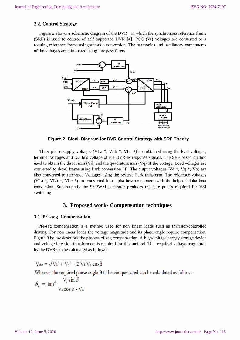
3.1. Pre-sag Compensation
Pre-sag compensation is a method used for non linear loads such as thyristor-controlled
driving. For non linear loads the voltage magnitude and its phase angle require compensation.
Figure 3 below describes the process of sag compensation. A high-voltage energy storage device
and voltage injection transformers is required for this method. The required voltage magnitude
by the DVR can be calculated as follows:
ISSN NO: 1934-7197
http://www.journaleca.com/ Page No: 115
Journal of Engineering, Computing and Architecture
Volume 10, Issue 5, 2020
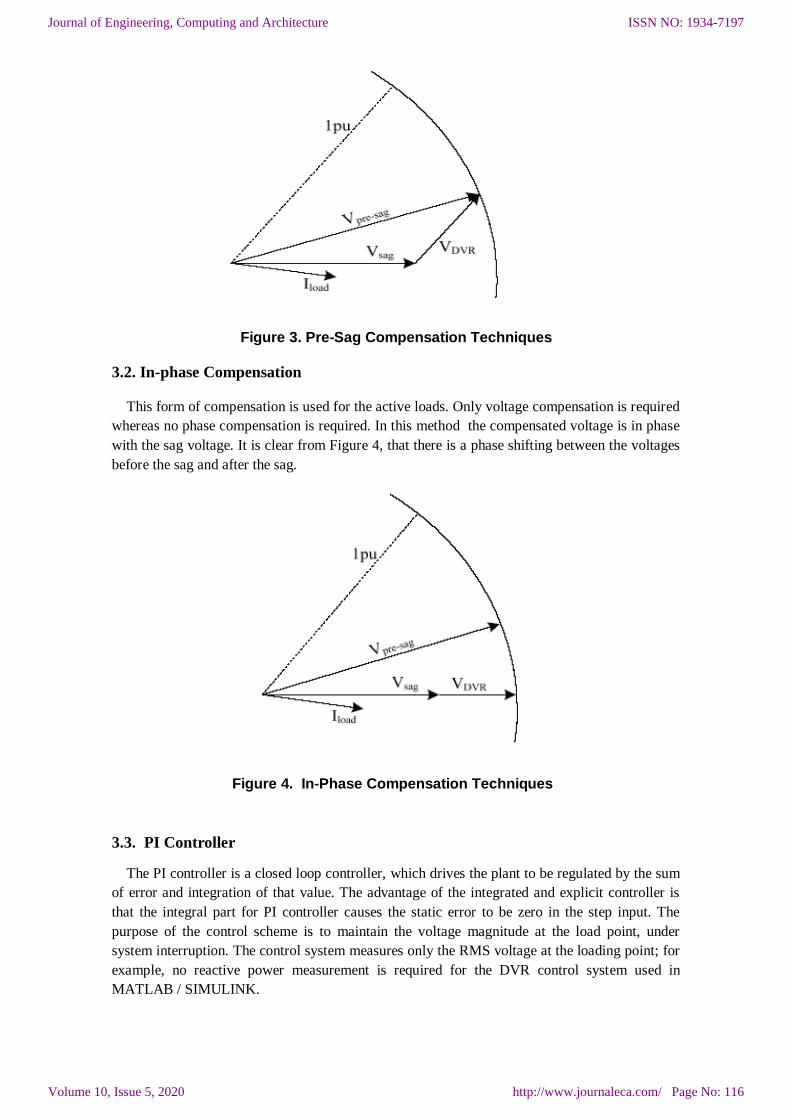
Figure 3. Pre-Sag Compensation Techniques
3.2. In-phase Compensation
This form of compensation is used for the active loads. Only voltage compensation is required
whereas no phase compensation is required. In this method the compensated voltage is in phase
with the sag voltage. It is clear from Figure 4, that there is a phase shifting between the voltages
before the sag and after the sag.
Figure 4. In-Phase Compensation Techniques
3.3. PI Controller
The PI controller is a closed loop controller, which drives the plant to be regulated by the sum
of error and integration of that value. The advantage of the integrated and explicit controller is
that the integral part for PI controller causes the static error to be zero in the step input. The
purpose of the control scheme is to maintain the voltage magnitude at the load point, under
system interruption. The control system measures only the RMS voltage at the loading point; for
example, no reactive power measurement is required for the DVR control system used in
MATLAB / SIMULINK.
ISSN NO: 1934-7197
http://www.journaleca.com/ Page No: 116
Journal of Engineering, Computing and Architecture
Volume 10, Issue 5, 2020
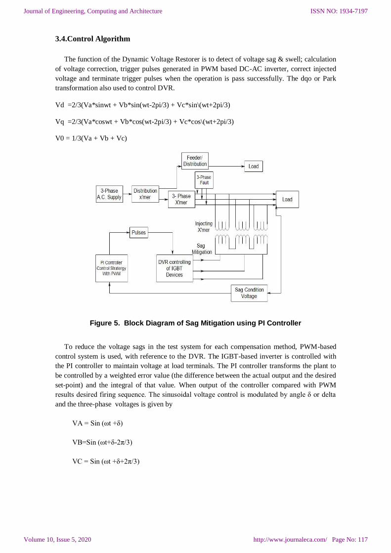
3.4.Control Algorithm
The function of the Dynamic Voltage Restorer is to detect of voltage sag & swell; calculation
of voltage correction, trigger pulses generated in PWM based DC-AC inverter, correct injected
voltage and terminate trigger pulses when the operation is pass successfully. The dqo or Park
transformation also used to control DVR.
Vd =2/3(Va*sinwt + Vb*sin(wt-2pi/3) + Vc*sin\(wt+2pi/3)
Vq =2/3(Va*coswt + Vb*cos(wt-2pi/3) + Vc*cos\(wt+2pi/3)
V0 = 1/3(Va + Vb + Vc)
Figure 5. Block Diagram of Sag Mitigation using PI Controller
To reduce the voltage sags in the test system for each compensation method, PWM-based
control system is used, with reference to the DVR. The IGBT-based inverter is controlled with
the PI controller to maintain voltage at load terminals. The PI controller transforms the plant to
be controlled by a weighted error value (the difference between the actual output and the desired
set-point) and the integral of that value. When output of the controller compared with PWM
results desired firing sequence. The sinusoidal voltage control is modulated by angle δ or delta
and the three-phase voltages is given by
VA = Sin (ωt +δ)
VB=Sin (ωt+δ-2π/3)
VC = Sin (ωt +δ+2π/3)
ISSN NO: 1934-7197
http://www.journaleca.com/ Page No: 117
Journal of Engineering, Computing and Architecture
Volume 10, Issue 5, 2020
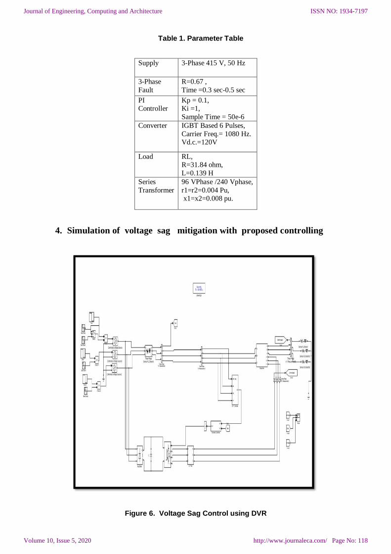
Table 1. Parameter Table
Supply 3-Phase 415 V, 50 Hz
3-Phase
Fault
R=0.67 ,
Time =0.3 sec-0.5 sec
PI Controller
Kp = 0.1, Ki =1,
Sample Time = 50e-6
Converter IGBT Based 6 Pulses,
Carrier Freq.= 1080 Hz. Vd.c.=120V
Load RL, R=31.84 ohm,
L=0.139 H
Series
Transformer
96 VPhase /240 Vphase,
r1=r2=0.004 Pu, x1=x2=0.008 pu.
4. Simulation of voltage sag mitigation with proposed controlling
Figure 6. Voltage Sag Control using DVR
ISSN NO: 1934-7197
http://www.journaleca.com/ Page No: 118
Journal of Engineering, Computing and Architecture
Volume 10, Issue 5, 2020
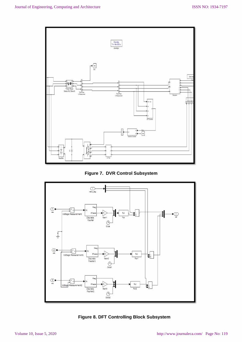
Figure 7. DVR Control Subsystem
Figure 8. DFT Controlling Block Subsystem
ISSN NO: 1934-7197
http://www.journaleca.com/ Page No: 119
Journal of Engineering, Computing and Architecture
Volume 10, Issue 5, 2020
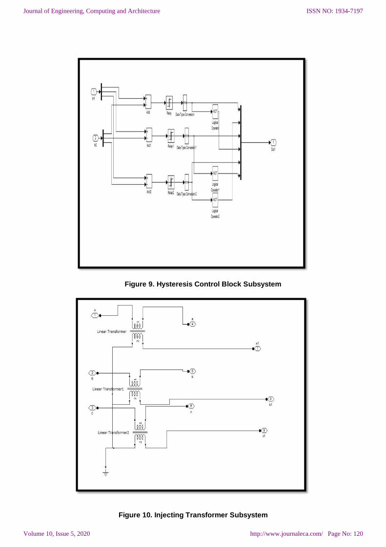
Figure 9. Hysteresis Control Block Subsystem
Figure 10. Injecting Transformer Subsystem
ISSN NO: 1934-7197
http://www.journaleca.com/ Page No: 120
Journal of Engineering, Computing and Architecture
Volume 10, Issue 5, 2020
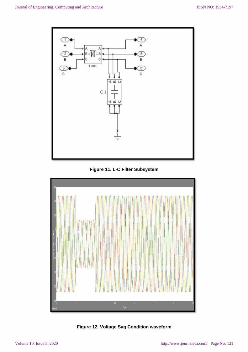
Figure 11. L-C Filter Subsystem
Figure 12. Voltage Sag Condition waveform
ISSN NO: 1934-7197
http://www.journaleca.com/ Page No: 121
Journal of Engineering, Computing and Architecture
Volume 10, Issue 5, 2020
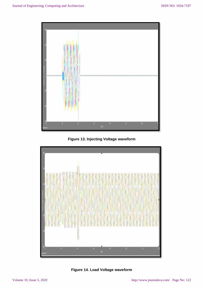
Figure 13. Injecting Voltage waveform
Figure 14. Load Voltage waveform
ISSN NO: 1934-7197
http://www.journaleca.com/ Page No: 122
Journal of Engineering, Computing and Architecture
Volume 10, Issue 5, 2020
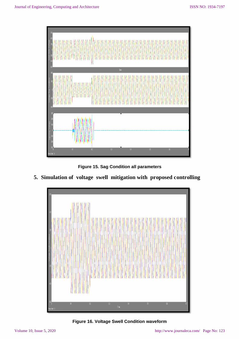
Figure 15. Sag Condition all parameters
5. Simulation of voltage swell mitigation with proposed controlling
Figure 16. Voltage Swell Condition waveform
ISSN NO: 1934-7197
http://www.journaleca.com/ Page No: 123
Journal of Engineering, Computing and Architecture
Volume 10, Issue 5, 2020
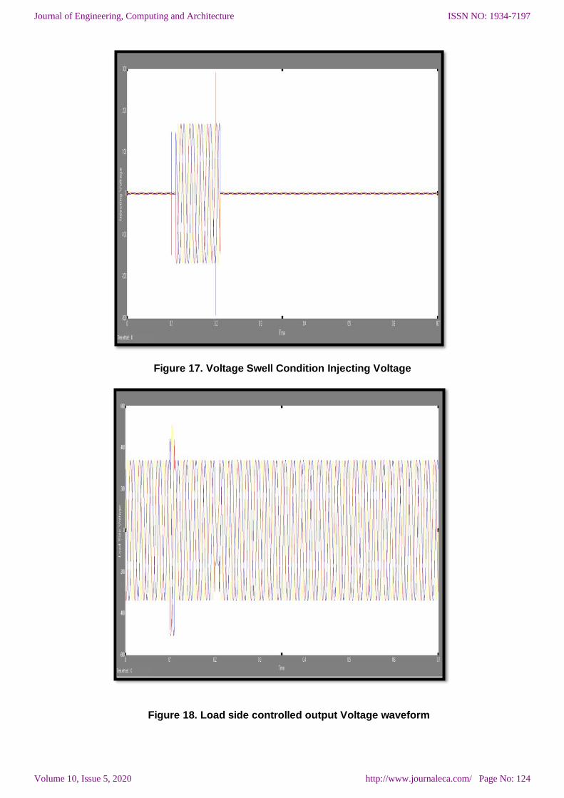
Figure 17. Voltage Swell Condition Injecting Voltage
Figure 18. Load side controlled output Voltage waveform
ISSN NO: 1934-7197
http://www.journaleca.com/ Page No: 124
Journal of Engineering, Computing and Architecture
Volume 10, Issue 5, 2020
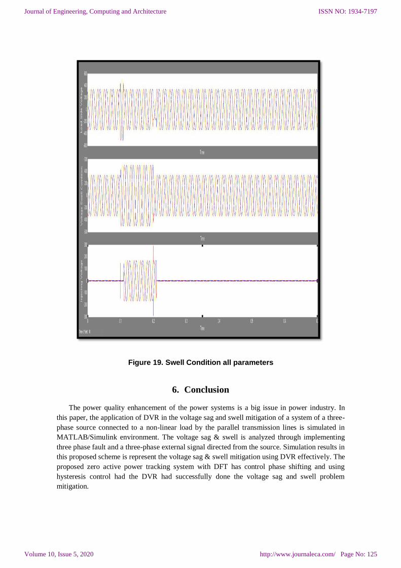
Figure 19. Swell Condition all parameters
6. Conclusion
The power quality enhancement of the power systems is a big issue in power industry. In
this paper, the application of DVR in the voltage sag and swell mitigation of a system of a three-
phase source connected to a non-linear load by the parallel transmission lines is simulated in
MATLAB/Simulink environment. The voltage sag & swell is analyzed through implementing
three phase fault and a three-phase external signal directed from the source. Simulation results in
this proposed scheme is represent the voltage sag & swell mitigation using DVR effectively. The
proposed zero active power tracking system with DFT has control phase shifting and using
hysteresis control had the DVR had successfully done the voltage sag and swell problem
mitigation.
ISSN NO: 1934-7197
http://www.journaleca.com/ Page No: 125
Journal of Engineering, Computing and Architecture
Volume 10, Issue 5, 2020
7. Acknowledgement
I wish to thank my guide Dr. V. R. Patel for his inspiration and continuous support. Without
his valuable advice and assistance, it would not have been possible for me to attain this landmark.
He has always been willingly present whenever I needed the slightest support from him. I would
not like to miss a chance to say thanks for the time that spared for me, from his extremely busy
schedule.
REFERENCES
[1] Gheorghe Ioan Nicolaescu, Horia Andrei, Stefan Raduulescu , “DVR with DC Voltage
Source Provided by A High Power Diode Rectifier Used in MV Connection Substations”, 978-1-4799-7514-3/15/©2015 IEEE.
[2] Gheorghe Ioan Nicolaescu, Horia Andrei, Stefan Radulescu, “Improvement in
Electricity Distribution Services Using a DVR with DC Voltage Source Installed in MV
Connection Substations", 978-1-4799-7993-6/15/©2015 IEEE.
[3] F.A.L. Jowder, “Design & analysis of dynamic voltage restorer for voltage sag and
harmonic compensation”, IET Generation, Transmission & Distribution , 2009, Vol. 3, Issue. 6, pp. 547–560.
[4] Gheorghe Nicolaescu, Horia Andrei, Stefan Radulescu, “DVR Response Analysis for
Voltage Sags Mitigation in MV Connection Substations with Secondary Distribution
System ”, 978-1-4799-4660-0/14/©2014 IEEE.
[5] Gheorghe-Ioan Nicolaescu, Horia Andrei, Stefan Radulescu, “Modeling and Simulation of DVR for Voltage Sags Mitigation in MV Networks with Secondary Distribution
System”, 978-1-4799-5183-3/14/2014 IEEE.
[6] Naidu, and D. Fernandes, “DVR based on a four-leg voltage source converter,” IET
Generation, Transmission & Distribution, vol. 3, no. 5, pp. 437–447, May 2009.
[7] Jimichi, H. Fujita, and H. Akagi, “A DVR equipped with a high frequency isolated dc-dc converter,” IEEE Trans. Ind. Appl., vol. 47, no. 1, pp. 169– 175, Jan. 2011.
[8] F. B. Ajaei, S. Farhangi, and R. Iravani, “Fault current interruption by the DVR,” IEEE
Trans. Power Del., vol. 28, no. 2, pp. 903–910, Apr. 2013.
[9] P. Roncero-Sánchez, E. Acha, J. E. Ortega-Calderon, V. Feliu, and A. García-Cerrada,
“A versatile control scheme for a DVR for power-quality improvement,” IEEE Trans.
Power Del., vol. 24, no. 1, pp. 277–284, Jan. 2009.
[10] R. Gupta, A. Ghosh, and A. Joshi, “Performance comparison of VSC-based shunt-series
compensators used for voltage control in distribution systems,” IEEE Trans. Power Del.,
vol. 26, no. 1, pp. 268–278, Jan. 2011.
[11] J. G. Nielsen, and F. Blaabjerg, “comparison of system topologies for DVR,” IEEE Trans. Ind. Appl., vol. 41, no. 5, pp. 1272–1280, Sep.-Oct. 2005.
[12] C. Wessels, F. Gebhardt, and F. W. Fuchs, “Fault ride through of a DFIG wind turbine
using a DVR during symmetrical and asymmetrical faults,” IEEE Trans. Power
Electron., vol. 26, no. 3, pp. 807–815, Mar. 2011.
ISSN NO: 1934-7197
http://www.journaleca.com/ Page No: 126
Journal of Engineering, Computing and Architecture
Volume 10, Issue 5, 2020