Embed Size (px)
Citation preview

Adafruit Ultimate GPS Logger ShieldCreated by lady ada
Last updated on 2016-10-20 03:45:33 PM UTC
23558
111112131617191919
212125252627272829292931323333
35
Guide Contents
Guide ContentsOverviewShield Headers
Assembly with male headersAssembly with stacking headers
Direct ConnectDirect Connection Using the Switch (Uno/Mega)Direct Connection with Jumpers on LeonardoTesting Direct ConnectionSending NMEA Commands via Direct ConnectSoft Serial ConnectParsing Data
If you're using an Uno/Duemilanove/Diecimila...If you're using a Leonardo..
SD LoggingSD Card Library UpdateBuilt In LoggingBuilt In LoggingLogging StatusDownloading DataUsing the GPS ToolLOCUS ParserAntenna, Battery and More!LEDsAntennasRTC Backup BatteryBreakout and Proto-areaDownloads
Schematic
F.A.Q.
© Adafruit Industries https://learn.adafruit.com/adafruit-ultimate-gps-logger-shield Page 2 of 36
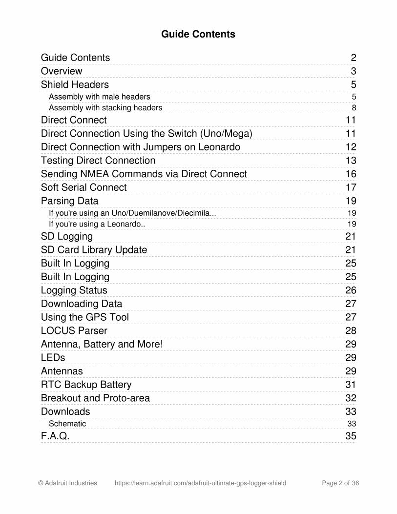
Overview
Brand new and better than ever, we've replaced our Adafruit GPS shield kit with thisassembled shield that comes with an Ultimate GPS module. This GPS shield works greatwith either UNO or Leonardo Arduinos and is designed to log data to an SD card. Or youcan leave the SD card out and use the GPS for a geocaching project, or maybe a musicplayer that changes tunes depending on where you are in the city.
-165 dBm sensitivity, 10 Hz updates, 66 channelsLow power module - only 20mA current draw, half of most GPS'sAssembled & tested shield for Arduino Uno/Duemilanove/Diecimila/LeonardoMicroSD card slot for datalogging onto a removable cardRTC battery included, for up to 7 years backupBuilt-in datalogging to flash
© Adafruit Industries https://learn.adafruit.com/adafruit-ultimate-gps-logger-shield Page 3 of 36

PPS output on fixInternal patch antenna + u.FL connector for external active antennaPower, Pin #13 and Fix status LEDBig prototyping area
Each order comes with one assembled and tested shield, a stick of 0.1" male header and a12mm coin cell. Some light soldering is required to attach the header to the shield in orderto plug it into your Arduino. if you want to stack a shield on top, be sure to pick up a set ofstacking headers to use instead.
If your project is going to be inside an enclosure, you'll love this shield as it has externalantenna support. Simply connect an external active GPS antenna (http://adafru.it/960) via auFL/SMA cable (http://adafru.it/851) to the shield and the module will automatically switchover to use the antenna. You can then place the antenna wherever you wish.
We think this is the Ultimate GPS shield and we also think you'll agree!
© Adafruit Industries https://learn.adafruit.com/adafruit-ultimate-gps-logger-shield Page 4 of 36
Shield HeadersThe Ultimate GPS Logger shield comes tested assembled with a GPS unit and microSDsocket already on it, but you'll still need need to put headers on so you can plug it into anArduino
We don't pre-assemble the headers on because there's two options! You can either useplain 0.1" male headers (included with the shield) or Arduino Shield Stackingheaders (http://adafru.it/85).
Assembly with male headers
Most people will be happy with assembling he shield with male headers. The nice thingabout using these is they don't add anything to the height of the project, and they make anice solid connection. However, you won't be able to stack another shield on top. Tradeoffs!
© Adafruit Industries https://learn.adafruit.com/adafruit-ultimate-gps-logger-shield Page 5 of 36
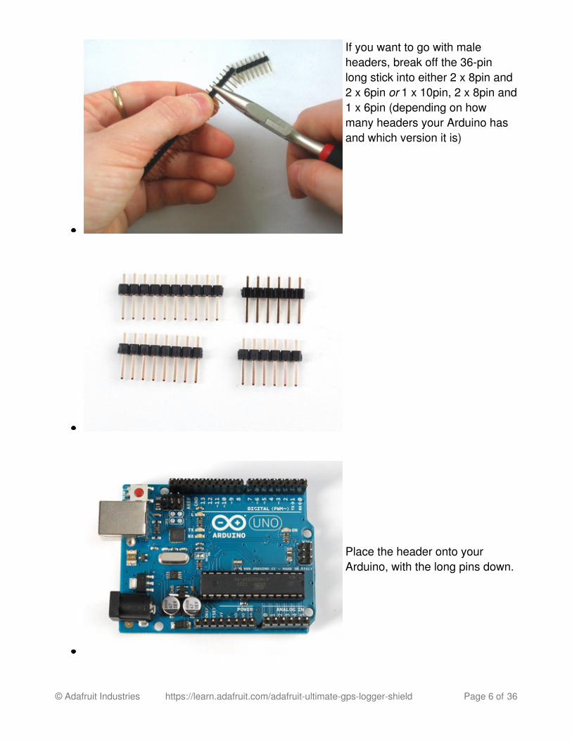
If you want to go with maleheaders, break off the 36-pinlong stick into either 2 x 8pin and2 x 6pin or 1 x 10pin, 2 x 8pin and1 x 6pin (depending on howmany headers your Arduino hasand which version it is)
Place the header onto yourArduino, with the long pins down.
© Adafruit Industries https://learn.adafruit.com/adafruit-ultimate-gps-logger-shield Page 6 of 36

Place the shield on top so theshort ends stick out thru thePCB, solder all the pins
© Adafruit Industries https://learn.adafruit.com/adafruit-ultimate-gps-logger-shield Page 7 of 36
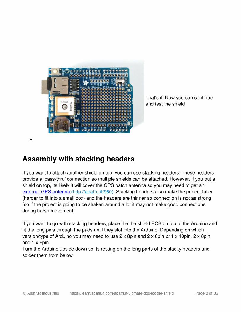
That's it! Now you can continueand test the shield
Assembly with stacking headers
If you want to attach another shield on top, you can use stacking headers. These headersprovide a 'pass-thru' connection so multiple shields can be attached. However, if you put ashield on top, its likely it will cover the GPS patch antenna so you may need to get anexternal GPS antenna (http://adafru.it/960). Stacking headers also make the project taller(harder to fit into a small box) and the headers are thinner so connection is not as strong(so if the project is going to be shaken around a lot it may not make good connectionsduring harsh movement)
If you want to go with stacking headers, place the the shield PCB on top of the Arduino andfit the long pins through the pads until they slot into the Arduino. Depending on whichversion/type of Arduino you may need to use 2 x 8pin and 2 x 6pin or 1 x 10pin, 2 x 8pinand 1 x 6pin.Turn the Arduino upside down so its resting on the long parts of the stacky headers andsolder them from below
© Adafruit Industries https://learn.adafruit.com/adafruit-ultimate-gps-logger-shield Page 8 of 36

If you want to go with stackingheaders, place the the shieldPCB on top of the Arduino
Fit the long pins through thepads until they slot into theArduino. Depending on whichversion/type of Arduino you mayneed to use 2 x 8pin and 2 x 6pinor 1 x 10pin, 2 x 8pin and 1 x6pin.
Turn the Arduino upside down soits resting on the long parts of thestacky headers and solder themfrom below.
You may want to pull the headersout a little to get them to sit flatagainst the shield PCB
Solder all the pins!
© Adafruit Industries https://learn.adafruit.com/adafruit-ultimate-gps-logger-shield Page 9 of 36

© Adafruit Industries https://learn.adafruit.com/adafruit-ultimate-gps-logger-shield Page 10 of 36
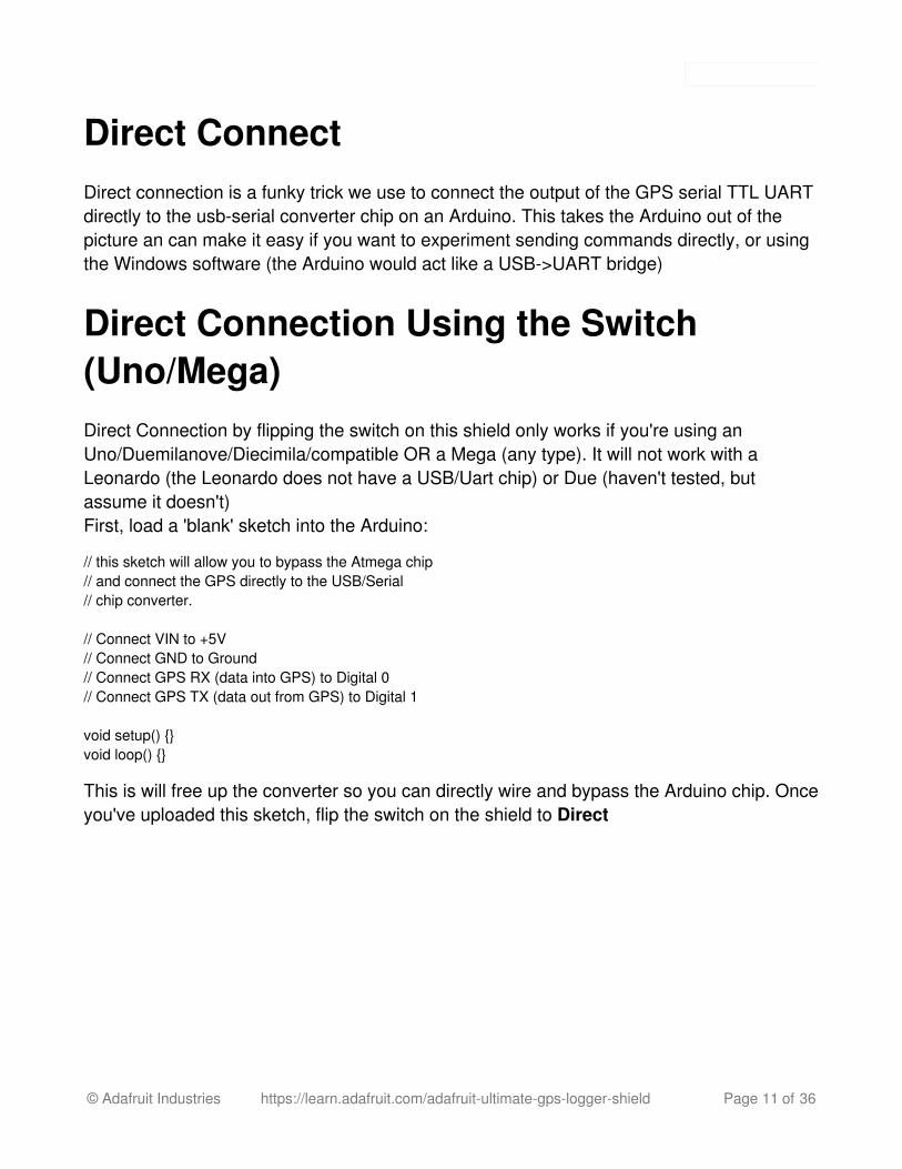
Direct ConnectDirect connection is a funky trick we use to connect the output of the GPS serial TTL UARTdirectly to the usb-serial converter chip on an Arduino. This takes the Arduino out of thepicture an can make it easy if you want to experiment sending commands directly, or usingthe Windows software (the Arduino would act like a USB->UART bridge)
Direct Connection Using the Switch(Uno/Mega)Direct Connection by flipping the switch on this shield only works if you're using anUno/Duemilanove/Diecimila/compatible OR a Mega (any type). It will not work with aLeonardo (the Leonardo does not have a USB/Uart chip) or Due (haven't tested, butassume it doesn't)First, load a 'blank' sketch into the Arduino:
// this sketch will allow you to bypass the Atmega chip// and connect the GPS directly to the USB/Serial// chip converter. // Connect VIN to +5V// Connect GND to Ground// Connect GPS RX (data into GPS) to Digital 0// Connect GPS TX (data out from GPS) to Digital 1 void setup() {}void loop() {}
This is will free up the converter so you can directly wire and bypass the Arduino chip. Onceyou've uploaded this sketch, flip the switch on the shield to Direct
© Adafruit Industries https://learn.adafruit.com/adafruit-ultimate-gps-logger-shield Page 11 of 36
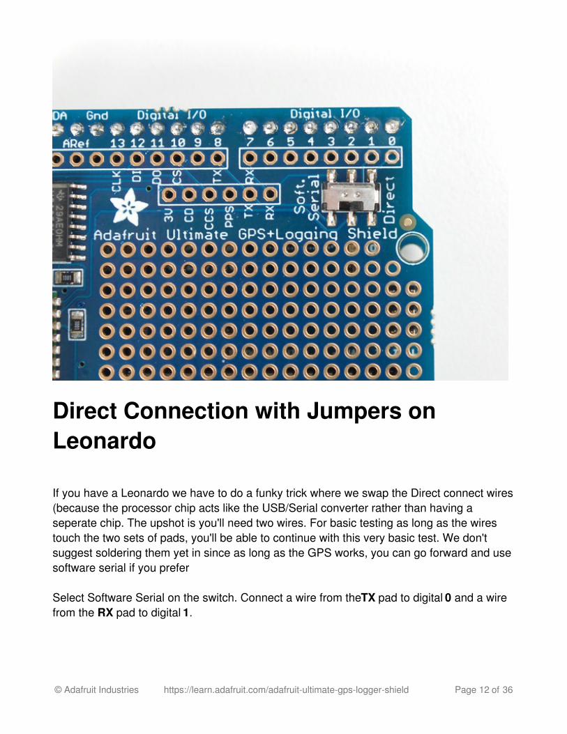
Direct Connection with Jumpers onLeonardo
If you have a Leonardo we have to do a funky trick where we swap the Direct connect wires(because the processor chip acts like the USB/Serial converter rather than having aseperate chip. The upshot is you'll need two wires. For basic testing as long as the wirestouch the two sets of pads, you'll be able to continue with this very basic test. We don'tsuggest soldering them yet in since as long as the GPS works, you can go forward and usesoftware serial if you prefer
Select Software Serial on the switch. Connect a wire from the TX pad to digital 0 and a wirefrom the RX pad to digital 1.
© Adafruit Industries https://learn.adafruit.com/adafruit-ultimate-gps-logger-shield Page 12 of 36
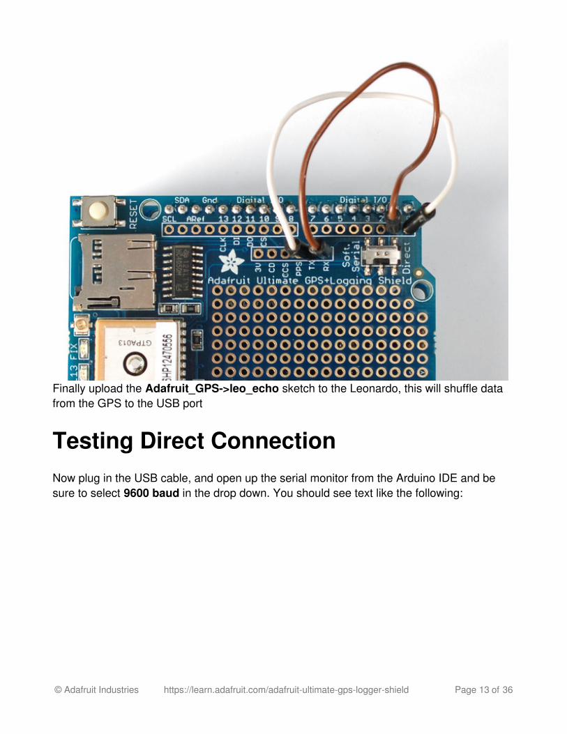
Finally upload the Adafruit_GPS->leo_echo sketch to the Leonardo, this will shuffle datafrom the GPS to the USB port
Testing Direct ConnectionNow plug in the USB cable, and open up the serial monitor from the Arduino IDE and besure to select 9600 baud in the drop down. You should see text like the following:
© Adafruit Industries https://learn.adafruit.com/adafruit-ultimate-gps-logger-shield Page 13 of 36
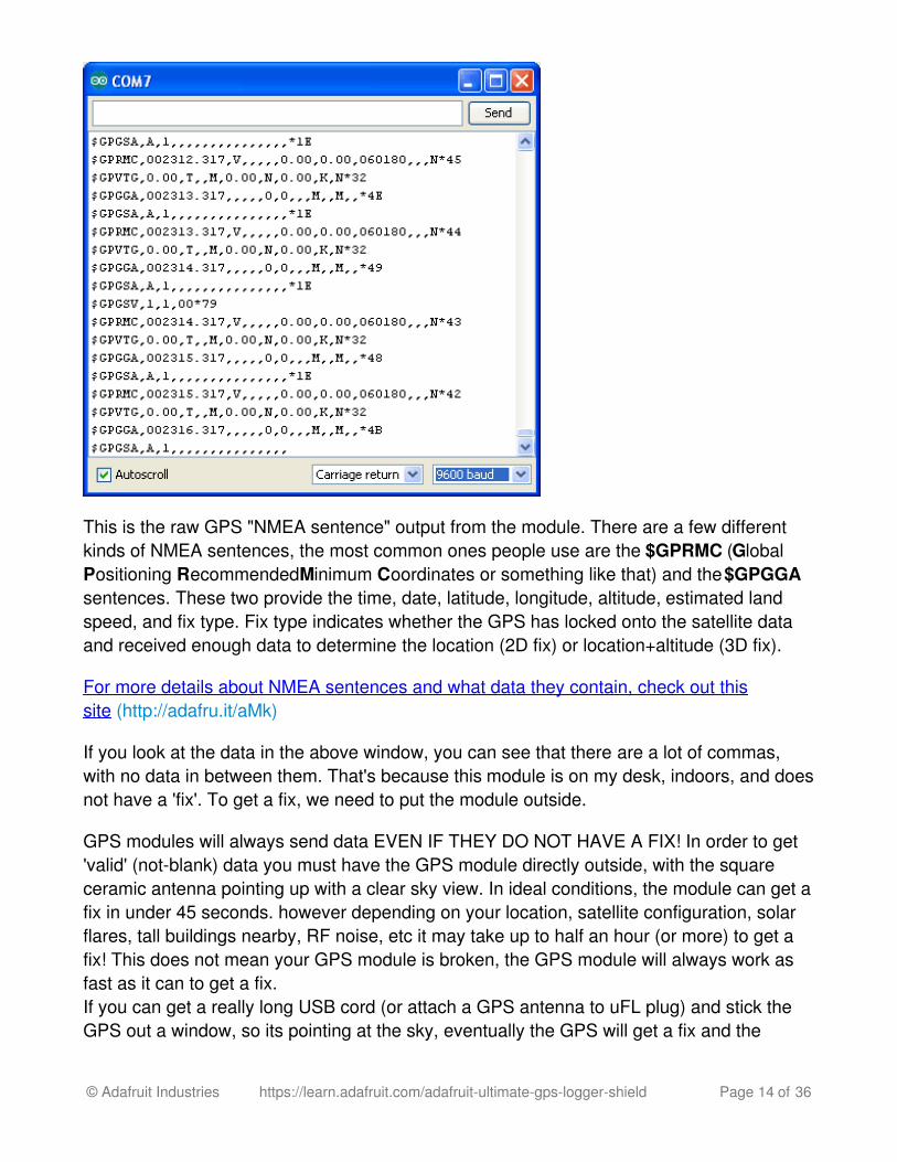
This is the raw GPS "NMEA sentence" output from the module. There are a few differentkinds of NMEA sentences, the most common ones people use are the $GPRMC (GlobalPositioning RecommendedMinimum Coordinates or something like that) and the $GPGGAsentences. These two provide the time, date, latitude, longitude, altitude, estimated landspeed, and fix type. Fix type indicates whether the GPS has locked onto the satellite dataand received enough data to determine the location (2D fix) or location+altitude (3D fix).
For more details about NMEA sentences and what data they contain, check out thissite (http://adafru.it/aMk)
If you look at the data in the above window, you can see that there are a lot of commas,with no data in between them. That's because this module is on my desk, indoors, and doesnot have a 'fix'. To get a fix, we need to put the module outside.
GPS modules will always send data EVEN IF THEY DO NOT HAVE A FIX! In order to get'valid' (not-blank) data you must have the GPS module directly outside, with the squareceramic antenna pointing up with a clear sky view. In ideal conditions, the module can get afix in under 45 seconds. however depending on your location, satellite configuration, solarflares, tall buildings nearby, RF noise, etc it may take up to half an hour (or more) to get afix! This does not mean your GPS module is broken, the GPS module will always work asfast as it can to get a fix.If you can get a really long USB cord (or attach a GPS antenna to uFL plug) and stick theGPS out a window, so its pointing at the sky, eventually the GPS will get a fix and the
© Adafruit Industries https://learn.adafruit.com/adafruit-ultimate-gps-logger-shield Page 14 of 36
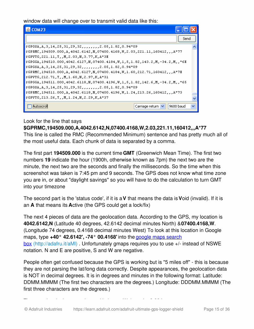
window data will change over to transmit valid data like this:
Look for the line that says$GPRMC,194509.000,A,4042.6142,N,07400.4168,W,2.03,221.11,160412,,,A*77 This line is called the RMC (Recommended Minimum) sentence and has pretty much all ofthe most useful data. Each chunk of data is separated by a comma.
The first part 194509.000 is the current time GMT (Greenwich Mean Time). The first twonumbers 19 indicate the hour (1900h, otherwise known as 7pm) the next two are theminute, the next two are the seconds and finally the milliseconds. So the time when thisscreenshot was taken is 7:45 pm and 9 seconds. The GPS does not know what time zoneyou are in, or about "daylight savings" so you will have to do the calculation to turn GMTinto your timezone
The second part is the 'status code', if it is a V that means the data is Void (invalid). If it isan A that means its Active (the GPS could get a lock/fix)
The next 4 pieces of data are the geolocation data. According to the GPS, my location is4042.6142,N (Latitude 40 degrees, 42.6142 decimal minutes North) & 07400.4168,W.(Longitude 74 degrees, 0.4168 decimal minutes West) To look at this location in Googlemaps, type +40° 42.6142', -74° 00.4168' into the google maps searchbox (http://adafru.it/aMl) . Unfortunately gmaps requires you to use +/- instead of NSWEnotation. N and E are positive, S and W are negative.
People often get confused because the GPS is working but is "5 miles off" - this is becausethey are not parsing the lat/long data correctly. Despite appearances, the geolocation datais NOT in decimal degrees. It is in degrees and minutes in the following format: Latitude:DDMM.MMMM (The first two characters are the degrees.) Longitude: DDDMM.MMMM (Thefirst three characters are the degrees.)
The next data is the ground speed in knots. We're going 2.03 knots
© Adafruit Industries https://learn.adafruit.com/adafruit-ultimate-gps-logger-shield Page 15 of 36
The next data is the ground speed in knots. We're going 2.03 knots
After that is the tracking angle, this is meant to approximate what 'compass' direction we'reheading at based on our past travel
The one after that is 160412 which is the current date (16th of April, 2012).
Finally there is the *XX data which is used as a data transfer checksum
Once you get a fix using your GPS module, verify your location with google maps (or someother mapping software). Remember that GPS is often only accurate to 5-10 meters andworse if you're indoors or surrounded by tall buildings.
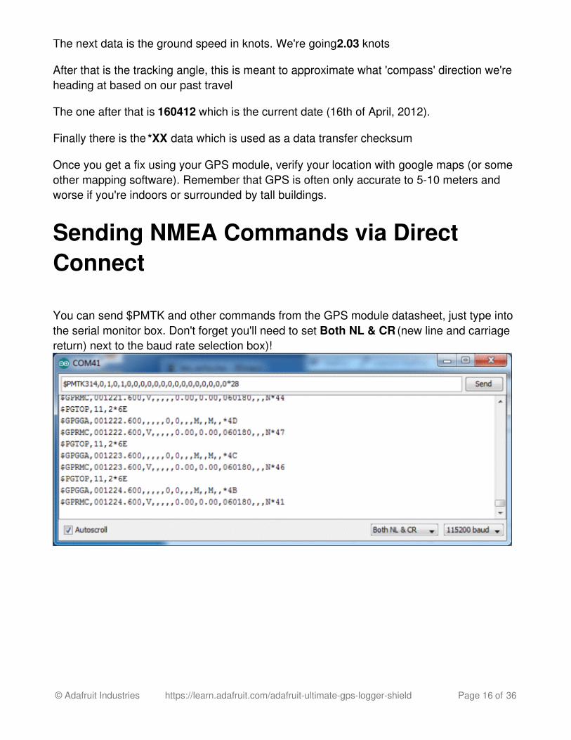
Sending NMEA Commands via DirectConnect
You can send $PMTK and other commands from the GPS module datasheet, just type intothe serial monitor box. Don't forget you'll need to set Both NL & CR (new line and carriagereturn) next to the baud rate selection box)!
© Adafruit Industries https://learn.adafruit.com/adafruit-ultimate-gps-logger-shield Page 16 of 36

Soft Serial ConnectOnce you've gotten the GPS module tested with direct wiring, we can go forward and set itup for Soft Serial connection. The soft serial connection works by setting up a secondaryUART on two pins (digital 7 and 8) so that the main UART is free for debugging &uploading sketchesSoft Serial connection works on Uno/Duemilanove/Diecimila Arduinos as well asLeonardos. It does not work on Mega as the Mega does not have Soft Serial support onpins 7 & 8
Next up, download the Adafruit GPS library. This library does a lot of the 'heavy lifting'required for receiving data from GPS modules, such as reading the steaming data in abackground interrupt and auto-magically parsing it. To download it, visit the GitHubrepository and click the ZIP button in the top bar (http://adafru.it/aMm) , rename theuncompressed folder Adafruit_GPS. Check that the Adafruit_GPS folder containsAdafruit_GPS.cpp and Adafruit_GPS.h
Place the Adafruit_GPS library folder your sketchbookfolder/libraries/ folder. You may
© Adafruit Industries https://learn.adafruit.com/adafruit-ultimate-gps-logger-shield Page 17 of 36
Place the Adafruit_GPS library folder your sketchbookfolder/libraries/ folder. You mayneed to create the libraries subfolder if its your first library. Restart the IDE. You can figureout your sketchbookfolder by opening up the Preferences tab in the Arduino IDE.
Open up the File→Examples→Adafruit_GPS→leo_echo sketch and upload it to theArduino. Then open up the serial monitor. This sketch simply reads data from the softwareserial port (pins 7&8) and outputs that to the hardware serial port connected to USB.
You can configure the output you see by commenting/uncommenting lines in the setup()procedure. For example, we can ask the GPS to send different sentences, and change howoften it sends data. 10 Hz (10 times a second) is the max speed, and is a lot of data. Youmay not be able to output "all data" at that speed because the 9600 baud rate is not fastenough.
In general, we find that most projects only need the RMC and GGA NMEA's so you don'tneed ALLDATA unless you have some need to know satellite locations.
© Adafruit Industries https://learn.adafruit.com/adafruit-ultimate-gps-logger-shield Page 18 of 36
Parsing DataSince all GPS's output NMEA sentences and often for our projects we need to extract theactual data from them, we've simplified the task tremendously when using the Adafruit GPSlibrary. By having the library read, store and parse the data in a background interrupt itbecomes trivial to query the library and get the latest updated information without any ickyparsing work.
If you're using an Uno/Duemilanove/Diecimila...
Make sure the switch is set to SoftSerial
Open up the File→Examples→Adafruit_GPS→parsing sketch and change the line
SoftwareSerial mySerial(3, 2);
to
SoftwareSerial mySerial(8, 7);
and upload it to the Arduino. Then open up the serial monitor.
If you're using a Leonardo..
Make sure the switch is set to SoftSerial
Change SoftwareSerial mySerial(3, 2); to SoftwareSerial mySerial(8, 7); as above, andalso change
useInterrupt(true);
to
useInterrupt(false);
Because due to strange internal-details stuff, we cant use Software Serial, interrupts andalso echo the output via USB at the same time on Leonardo.
You'll want to wait till you get a fix so stick the GPS out the window or use an antenna
© Adafruit Industries https://learn.adafruit.com/adafruit-ultimate-gps-logger-shield Page 19 of 36

In this sketch, we can either use interrupts and call GPS.read() within a once-a-millisecondtimer (this is the same timer that runs the millis() command) or we check GPS.read() in themain loop constantly. Then in the main loop we can ask if a new chunk of data has beenreceived by calling GPS.newNMEAreceived(), if this returns true then we can ask thelibrary to parse that data with GPS.parse(GPS.lastNMEA()).
We do have to keep querying and parsing in the main loop - its not possible to do this in aninterrupt because then we'd be dropping GPS data by accident.
Once data is parsed, we can just ask for data from the library like GPS.day, GPS.monthand GPS.year for the current date. GPS.fix will be 1 if there is a fix, 0 if there is none. If wehave a fix then we can ask for GPS.latitude, GPS.longitude, GPS.speed (in knots, notmph or k/hr!), GPS.angle, GPS.altitude (in meters) and GPS.satellites (number ofsatellites)
This should make it much easier to have location-based projects. We suggest keeping theupdate rate at 1Hz and request that the GPS only output RMC and GGA as the parserdoes not keep track of other data anyways.
© Adafruit Industries https://learn.adafruit.com/adafruit-ultimate-gps-logger-shield Page 20 of 36
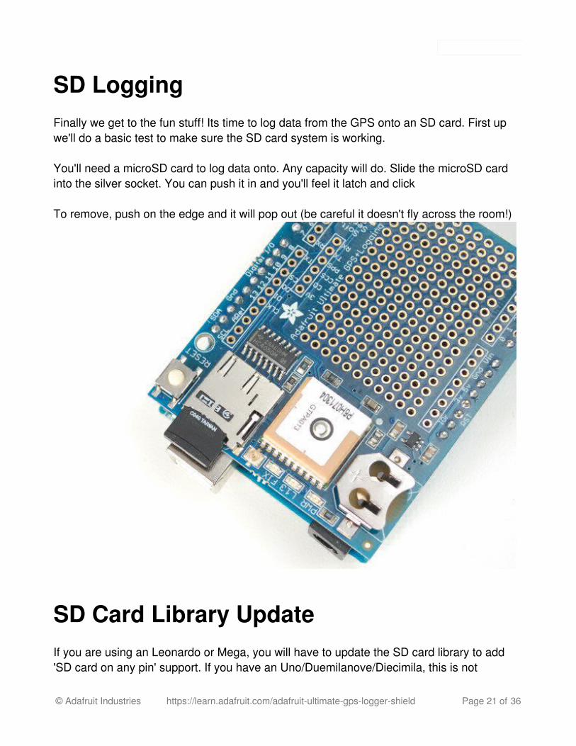
SD LoggingFinally we get to the fun stuff! Its time to log data from the GPS onto an SD card. First upwe'll do a basic test to make sure the SD card system is working.
You'll need a microSD card to log data onto. Any capacity will do. Slide the microSD cardinto the silver socket. You can push it in and you'll feel it latch and click
To remove, push on the edge and it will pop out (be careful it doesn't fly across the room!)
SD Card Library UpdateIf you are using an Leonardo or Mega, you will have to update the SD card library to add'SD card on any pin' support. If you have an Uno/Duemilanove/Diecimila, this is not
© Adafruit Industries https://learn.adafruit.com/adafruit-ultimate-gps-logger-shield Page 21 of 36
required.
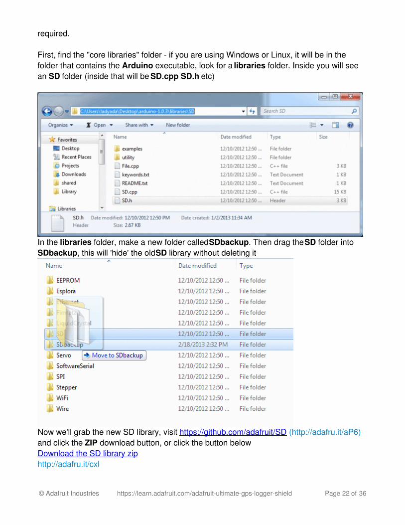
First, find the "core libraries" folder - if you are using Windows or Linux, it will be in thefolder that contains the Arduino executable, look for a libraries folder. Inside you will seean SD folder (inside that will be SD.cpp SD.h etc)
In the libraries folder, make a new folder called SDbackup. Then drag the SD folder intoSDbackup, this will 'hide' the old SD library without deleting it
Now we'll grab the new SD library, visit https://github.com/adafruit/SD (http://adafru.it/aP6)and click the ZIP download button, or click the button belowDownload the SD library ziphttp://adafru.it/cxl
© Adafruit Industries https://learn.adafruit.com/adafruit-ultimate-gps-logger-shield Page 22 of 36
Uncompress and rename the uncompressed folder SD. Check that the SD folder containsSD.cpp and SD.h
Place the SD library folder your sketchbook libraries folder. You may need to create thelibraries subfolder if its your first library. For more details on how to install libraries, checkout our ultra-detailed tutorial at (http://adafru.it/aYM)http://learn.adafruit.com/adafruit-all-about-arduino-libraries-install-use (http://adafru.it/aYM)
Once installed, restart the IDE. Then open up the Adafruit_GPS->shield_sdlog sketchand upload it to your Arduino.
If you're using a Leonardo, uncomment the line
// while (!Serial);
in the top of the Setup() function - this will help make debugging easier.
If you are using an Uno/Duemilanove/Diecimila or compatible, Find these two lines
if (!SD.begin(chipSelect, 11, 12, 13)) {//if (!SD.begin(chipSelect)) { // if you're using an UNO, you can use this lineinstead
And comment out the first one and uncomment the second one.
Make sure you have the switch set to Soft Serial and open up the serial monitor and checkthat you're connected at 115200 baud (or you'll get gibberish)
© Adafruit Industries https://learn.adafruit.com/adafruit-ultimate-gps-logger-shield Page 23 of 36
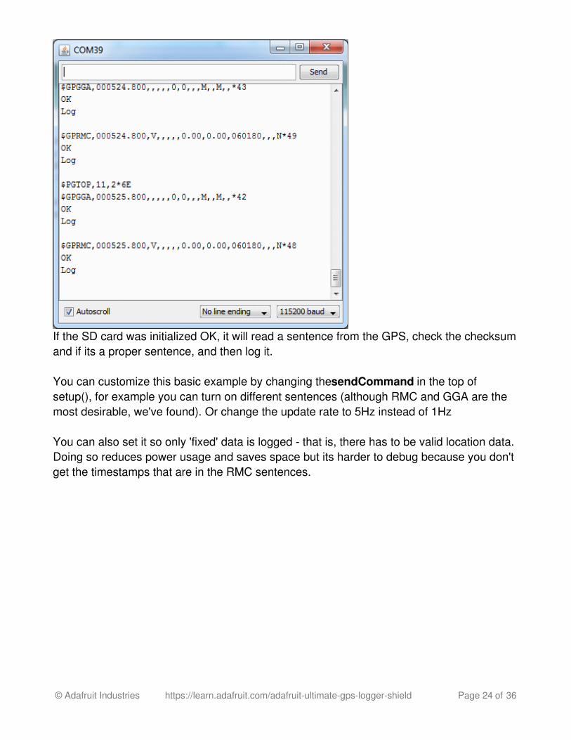
If the SD card was initialized OK, it will read a sentence from the GPS, check the checksumand if its a proper sentence, and then log it.
You can customize this basic example by changing the sendCommand in the top ofsetup(), for example you can turn on different sentences (although RMC and GGA are themost desirable, we've found). Or change the update rate to 5Hz instead of 1Hz
You can also set it so only 'fixed' data is logged - that is, there has to be valid location data.Doing so reduces power usage and saves space but its harder to debug because you don'tget the timestamps that are in the RMC sentences.
© Adafruit Industries https://learn.adafruit.com/adafruit-ultimate-gps-logger-shield Page 24 of 36
Built In LoggingThe built in logging capability isn't easy to use with the Shield - we wanted to make it betterfor SD logging so while we do have some details here, its not well supported and notrecommendedFor more details, you can read the LOCUS (built-in-datalogging system) userguide (http://adafru.it/dL2)
Built In LoggingOne of the nice things about the GPS module on the shield is the built in data-logger. Thisbasic data-logging capability can store date, time, latitude, longitude and altitude data into a64K flash chip inside. Its not a high resolution logger - it only logs once every 15 secondswhen there is a fix - but for some projects that want to track location, this can be a great lowpower way to log data - no SD card required! It can store up to ~16 hours of data.
The GPS module does require the Arduino to 'kick start' the logger by requesting it to start.If power is lost it will require another 'kick' to start. If you already have some data in theFLASH, a new trace will be created (so you wont lose old data) and if you run out of spaceit will simply halt and not overwrite old data. Despite this annoyance, its still a very niceextra and we have some library support to help you use it
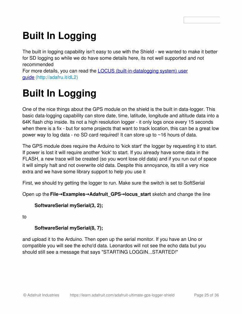
First, we should try getting the logger to run. Make sure the switch is set to SoftSerial
Open up the File→Examples→Adafruit_GPS→locus_start sketch and change the line
SoftwareSerial mySerial(3, 2);
to
SoftwareSerial mySerial(8, 7);
and upload it to the Arduino. Then open up the serial monitor. If you have an Uno orcompatible you will see the echo'd data. Leonardos will not see the echo data but youshould still see a message that says "STARTING LOGGIN...STARTED!"
© Adafruit Industries https://learn.adafruit.com/adafruit-ultimate-gps-logger-shield Page 25 of 36
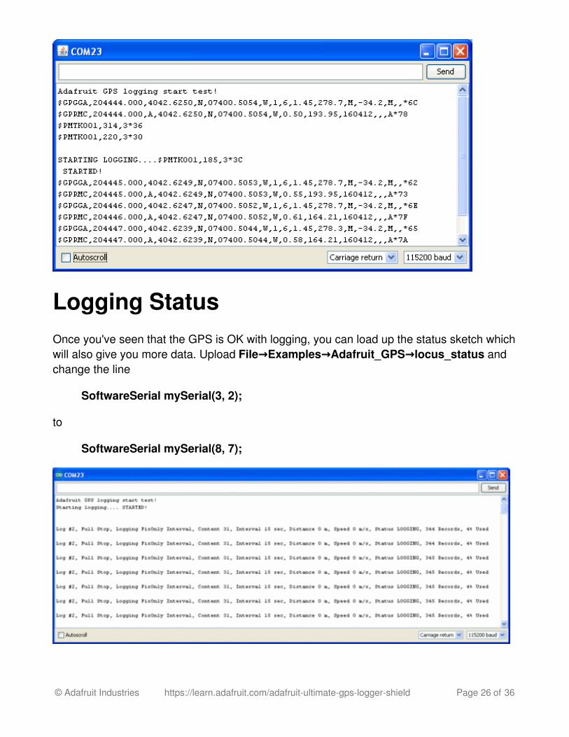
Logging StatusOnce you've seen that the GPS is OK with logging, you can load up the status sketch whichwill also give you more data. Upload File→Examples→Adafruit_GPS→locus_status andchange the line
SoftwareSerial mySerial(3, 2);
to
SoftwareSerial mySerial(8, 7);
© Adafruit Industries https://learn.adafruit.com/adafruit-ultimate-gps-logger-shield Page 26 of 36
Downloading DataFinally, once we're done logging we need to extract the data. To do this we need to first getthe raw data out of the FLASH and then decode the sentences.UploadFile→Examples→Adafruit_GPS→locus_dump to the Arduino and open up theserial monitor. Change the software serial line to use pins 8 and 7
PLEASE NOTE: Asking the Arduino, with 2K RAM buffer to handle 64KB of FLASH dataand spit it out from the GPS can sometimes over-tax the processor. If you are havinghiccups, check the GPS tool instructions below (http://adafru.it/aYN) Copy and paste all thetext after the —-'s (starting with $PMTKLOX,0,86*67 and ending with $PMTK001,622,3*36)then paste it into the box located on this page (http://adafru.it/cFg).
Using the GPS Tool If you are having difficulty with the Arduino/javascript tool, you can also try using the GPStool. The tool runs only under Windows but it is very powerful.
You can only do this with an Uno/Duemilanove/Diecimila/Mega!
You'll also need to set up direct wiring. Go back to the connect with Direct Wiringexample (http://adafru.it/aYO), and get that working. You'll FTDI adapter or other TTLconverter and download the GPS Tool (http://adafru.it/aOQ) - connect to the GPS via theCOM port of the Arduino/FTDI/TTL cable. You can then query, dump and delete the logmemory
© Adafruit Industries https://learn.adafruit.com/adafruit-ultimate-gps-logger-shield Page 27 of 36

LOCUS ParserLOCUS Parser (http://adafru.it/cFg)
© Adafruit Industries https://learn.adafruit.com/adafruit-ultimate-gps-logger-shield Page 28 of 36
Antenna, Battery and More!
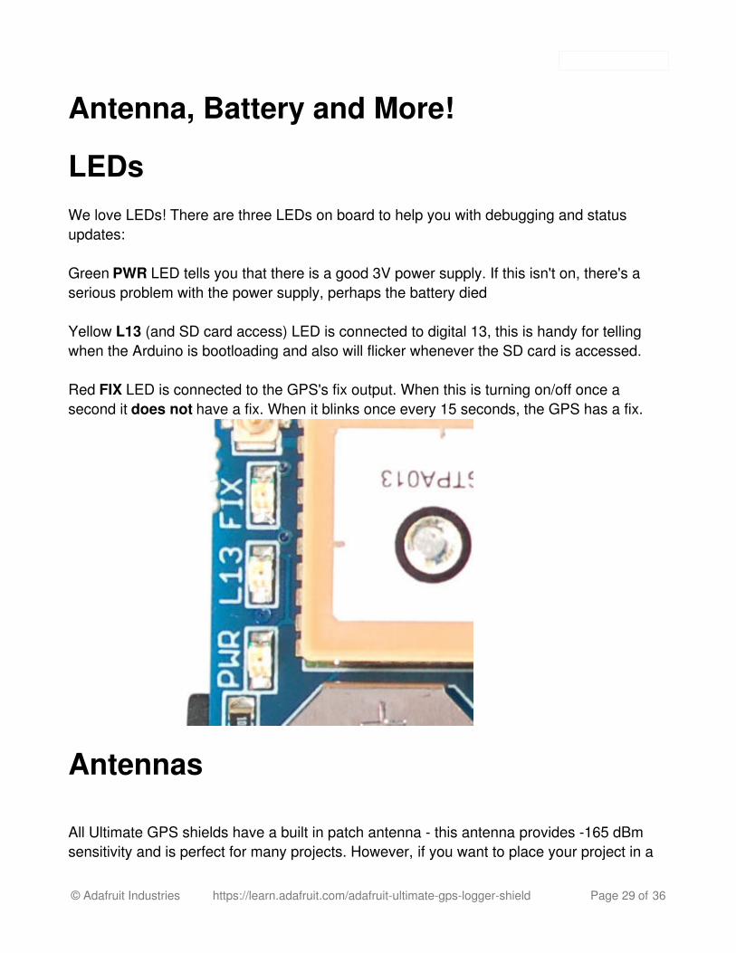
LEDsWe love LEDs! There are three LEDs on board to help you with debugging and statusupdates:
Green PWR LED tells you that there is a good 3V power supply. If this isn't on, there's aserious problem with the power supply, perhaps the battery died
Yellow L13 (and SD card access) LED is connected to digital 13, this is handy for tellingwhen the Arduino is bootloading and also will flicker whenever the SD card is accessed.
Red FIX LED is connected to the GPS's fix output. When this is turning on/off once asecond it does not have a fix. When it blinks once every 15 seconds, the GPS has a fix.
Antennas
All Ultimate GPS shields have a built in patch antenna - this antenna provides -165 dBmsensitivity and is perfect for many projects. However, if you want to place your project in a
© Adafruit Industries https://learn.adafruit.com/adafruit-ultimate-gps-logger-shield Page 29 of 36

box, it might not be possible to have the antenna pointing up, or it might be in a metalshield, or you may need more sensitivity. In these cases, you may want to use an externalactive antenna. (http://adafru.it/960)
Active antennas draw current, so they do provide more gain but at a power cost. Check theantenna datasheet for exactly how much current they draw - its usually around 10-20mA. (http://adafru.it/960)
Most GPS antennas use SMA connectors, which are popular and easy to use. However, anSMA connector would be fairly big on the GPS breakout so we went with a uFL connector -which is lightweight, small and easy to manufacture. If you don't need an external antenna itwont add significant weight or space but its easy to attach a uFL->SMA adaptercable (http://adafru.it/851). Then connect the GPS antenna to the cable.
The Ultimate GPS shield will automagically detect an external active antenna is attachedand 'switch over' - you do not need to send any commands
There is an output sentence that will tell you the status of the antenna. $PGTOP,11,xwhere x is the status number. If x is 3 that means it is using the external antenna. If x is 2it's using the internal antenna and if x is 1 there was an antenna short or problem. On
© Adafruit Industries https://learn.adafruit.com/adafruit-ultimate-gps-logger-shield Page 30 of 36

newer shields & modules, you'll need to tell the firmware you want to have this reportoutput, you can do that by adding a gps.sendCommand(PGCMD_ANTENNA) around thesame time you set the update rate/sentence output.
RTC Backup Battery
The Ultimate GPS module does not have a built in RTC battery, but a coin cell is provided,simply place the coin cell inside the holder, with the + facing up, thats it! The battery will last7+ years
The real time clock will automatically set itself to the correct UTC time as soon as the GPSgets its first correct signal from a satellite. Without the battery, if the GPS loses power, it willforget the time and has to wait till it gets signal again to reset. But, if you have the batteryin, it will keep time even after a power loss. We recommend it highly!
© Adafruit Industries https://learn.adafruit.com/adafruit-ultimate-gps-logger-shield Page 31 of 36
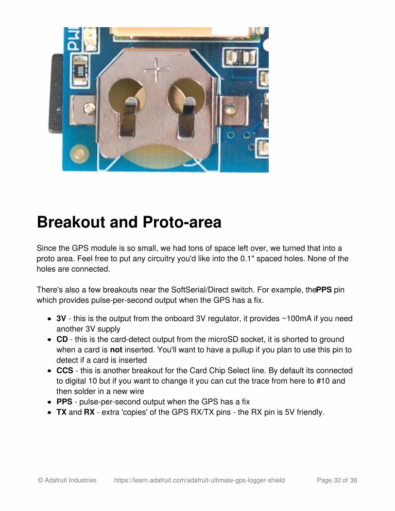
Breakout and Proto-areaSince the GPS module is so small, we had tons of space left over, we turned that into aproto area. Feel free to put any circuitry you'd like into the 0.1" spaced holes. None of theholes are connected.
There's also a few breakouts near the SoftSerial/Direct switch. For example, the PPS pinwhich provides pulse-per-second output when the GPS has a fix.
3V - this is the output from the onboard 3V regulator, it provides ~100mA if you needanother 3V supplyCD - this is the card-detect output from the microSD socket, it is shorted to groundwhen a card is not inserted. You'll want to have a pullup if you plan to use this pin todetect if a card is insertedCCS - this is another breakout for the Card Chip Select line. By default its connectedto digital 10 but if you want to change it you can cut the trace from here to #10 andthen solder in a new wirePPS - pulse-per-second output when the GPS has a fixTX and RX - extra 'copies' of the GPS RX/TX pins - the RX pin is 5V friendly.
© Adafruit Industries https://learn.adafruit.com/adafruit-ultimate-gps-logger-shield Page 32 of 36
DownloadsThere's also more information at the GPS module tutorial pagehttp://learn.adafruit.com/adafruit-ultimate-gps (http://adafru.it/aTl)
MTK3329/MTK3339 command set sheet (http://adafru.it/e7A) for changing the fixdata rate, baud rate, sentence outputs, etc!Datasheet for the PA6H (MTK3339) GPS module itself (http://adafru.it/aPO)MT3339 GPS PC Tool (windows only) (http://adafru.it/aMq) and the PC Toolmanual (http://adafru.it/aMr)Sample code and spec sheet for the LOCUS built-in logger (http://adafru.it/aTi)Mini GPS tool (windows only) (http://adafru.it/aMs)LOCUS (built-in-datalogging system) user guide (http://adafru.it/dL2)EagleCAD PCB files on GitHub (http://adafru.it/s9C)Fritzing object in the Adafruit Fritzing Library (http://adafru.it/aP3)
More reading:
Trimble's GPS tutorial (http://adafru.it/emh)Garmin's GPS tutorial (http://adafru.it/aMv)
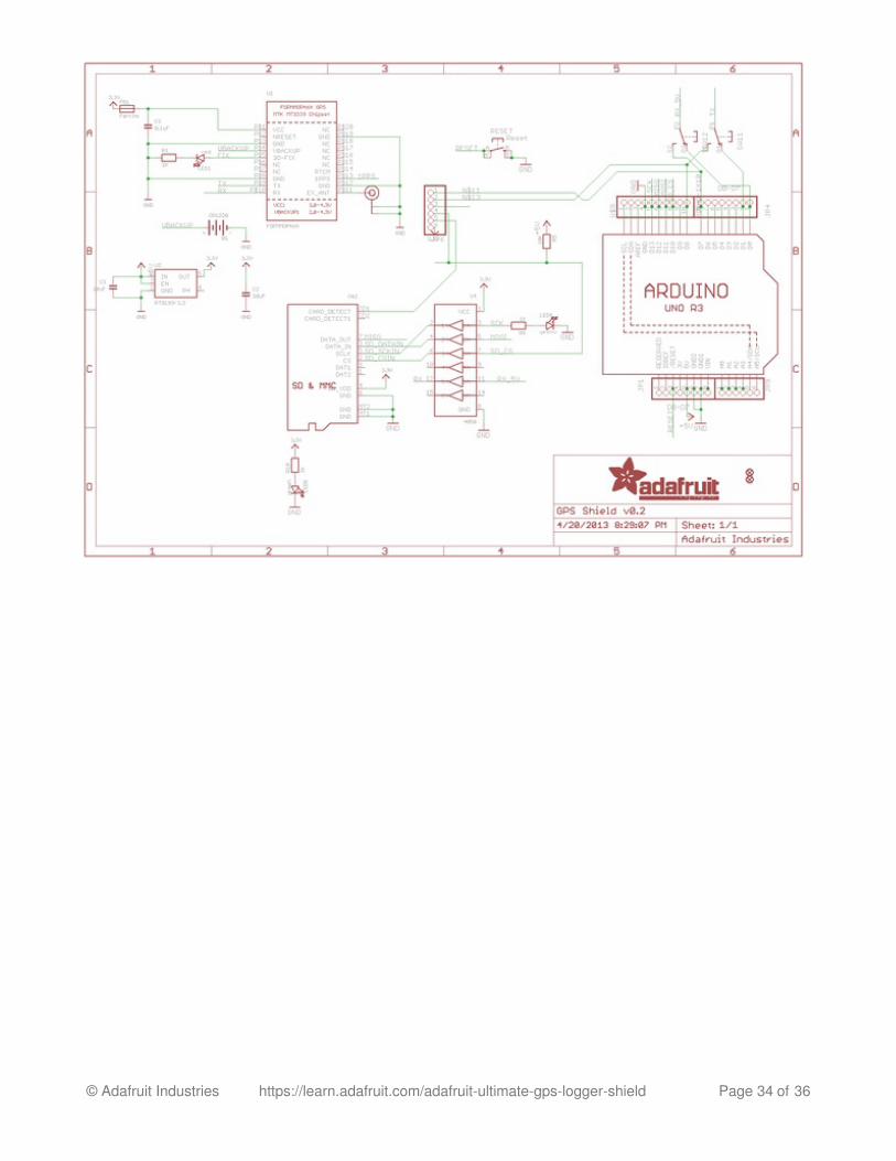
Schematic
© Adafruit Industries https://learn.adafruit.com/adafruit-ultimate-gps-logger-shield Page 33 of 36
© Adafruit Industries https://learn.adafruit.com/adafruit-ultimate-gps-logger-shield Page 34 of 36
F.A.Q.Can the Ultimate GPS be used for High Altitude? How can I know?
Modules shipped in 2013+ (and many in the later half of 2012) have firmware that has beentested by simulation at the GPS factory at 40km.
You can tell what firmware you have by sending the firmware query command$PMTK605*31 (you can use the echo demo to send custom sentences to your GPS)
If your module replies with AXN_2.10_3339_2012072601 5223 that means you haveversion #5223 which is the 40Km-supported firmware version. If the number is higher then5223 then its even more recent, and should include the 40Km support as well
HOWEVER these modules are not specifically designed for high-altitude balloon use.People have used them successfully but since we (at Adafruit) have not personally testedthem for hi-alt use, we do not in any way guarantee they are suitable for high altitude use.
Please do not ask us to 'prove' that they are good for high altitude use, we do nothave any way to do so
If you want to measure high altitude with a GPS, please find a module that canpromise/guarantee high altitude functionality
OK I want the latest firmware!
Here is the binary of the 5632 firmware (http://adafru.it/dR5), you can use this tool to uploadit using an FTDI or USB-TTL cable (or direct wiring with FTDI) (http://adafru.it/dR6). We donot have a tutorial for updating the firmware, if you update the firmware and somehow brickthe GPS, we do not offer replacements! Keep this in mind before performing the updateprocess!
I've adapted the example code and my GPS NMEA sentences are all garbled andincomplete!We use SoftwareSerial to read from the GPS, which is 'bitbang' UART support. It isn't supergreat on the Arduino and does work but adding too many delay()s and not calling the GPSdata parser enough will cause it to choke on data.
If you are using Leonardo (or Micro/Flora/ATmega32u4) or Mega, consider using aHardwareSerial port instead of SoftwareSerial!
© Adafruit Industries https://learn.adafruit.com/adafruit-ultimate-gps-logger-shield Page 35 of 36
How come I can't get the GPS to output at 10Hz?The default baud rate to the GPS is 9600 - this can only do RMC messages at 10Hz. If youwant more data output, you can increase the GPS baud rate (to 57600 for example) or gowith something like 2 or 5Hz. There is a trade off with more data you want the GPS tooutput, the GPS baud rate, Arduino buffer/processing capability and update rate!
Experimentation may be necessary to get the optimal results. We suggest RMC only for10Hz since we've tested it.How come I can't set the RTC with the Adafruit RTC library?The real time clock in the GPS is NOT 'writable' or accessable otherwise from the Arduino.Its in the GPS only! Once the battery is installed, and the GPS gets its first data receptionfrom satellites it will set the internal RTC. Then as long as the battery is installed, you canread the time from the GPS as normal. Even without a proper "gps fix" the time will becorrect.
The timezone cannot be changed, so you'll have to calculate local time based on UTC!
© Adafruit Industries Last Updated: 2016-10-20 03:45:32 PM UTC Page 36 of 36

![GPRS Data Logger [built in GPS] GS902 · PDF fileGPRS Data Logger [built in GPS] Server Software. Edition Centre Premium [A](https://img.pdfslide.us/doc/110x75/5a82763c7f8b9a9d308e06b9/gprs-data-logger-built-in-gps-gs902-data-logger-built-in-gps-server-software.jpg)


![Holux Wireless GPS Logger - [ ]](https://img.pdfslide.us/doc/110x75/61fb84c32e268c58cd5f1fcb/holux-wireless-gps-logger-.jpg)