Embed Size (px)
Citation preview
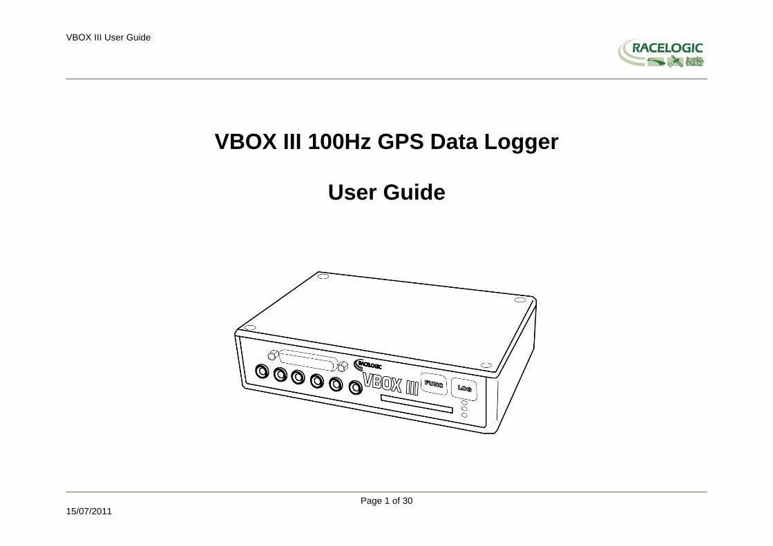
VBOX III User Guide
Page 1 of 30
15/07/2011
VBOX III 100Hz GPS Data Logger
User Guide

VBOX III User Guide
Page 2 of 30
15/07/2011
VBOX III OVERVIEW ......................................................................................................................................................................................................................................... 4
INTRODUCTION .................................................................................................................................................................................................................................................. 5
FEATURES ............................................................................................................................................................................................................................................................. 5
OPTIONAL ACCESSORIES ................................................................................................................................................................................................................................ 6
OPERATION .......................................................................................................................................................................................................................................................... 7
GETTING STARTED .......................................................................................................................................................................................................................................... 16
VBOX III ‘.VBO’ FILE FORMAT ..................................................................................................................................................................................................................... 18
VBOXTOOLS SOFTWARE ............................................................................................................................................................................................................................... 19
LOCAL DGPS BASESTATION ......................................................................................................................................................................................................................... 20
TROUBLESHOOTING GUIDE ......................................................................................................................................................................................................................... 21
FIRMWARE UPGRADES .................................................................................................................................................................................................................................. 22
SPECIFICATION ................................................................................................................................................................................................................................................ 23
CONNECTION DATA ........................................................................................................................................................................................................................................ 25
ANALOGUE INPUT CONNECTOR ................................................................................................................................................................................................................. 28
CAN BUS DATA FORMAT ................................................................................................................................................................................................................................ 29
CONTACT INFORMATION .............................................................................................................................................................................................................................. 30

VBOX III User Guide
Page 3 of 30
15/07/2011
EC Declaration of Conformity
We declare that this product has been tested to and meet the requirements of: EC Directive 2004/104/EC
“Adapting to Technical Progress Council directive 72/245/EEC relating to the radio interference (Electromagnetic Compatibility) of vehicles and amending directive 70/156/EEC on the approximation of the laws of the member states relating to the type-approval of motor vehicles and their trailers.” And has also been assessed, via Technical Construction File, by an independent DTI Competent Body and found to be in conformance with the essential requirements of: EC Directive 89/336/EEC (and amending directives)
“Council Directive of 03 May 1989 on the approximation of the laws of the member states relating to electromagnetic compatibility.”
DTI Competent Body responsible for issuing certificate of compliance:
3C Test Ltd, Silverstone Technology Park, Silverstone, Northants NN12 8GX

VBOX III User Guide
Page 4 of 30
15/07/2011
VBOX III Overview

VBOX III User Guide
Page 5 of 30
15/07/2011
Introduction The VBOX III represents the 3
rd generation of GPS data logging system from Racelogic. Using a powerful new GPS engine, the VBOX III can log GPS and
other data at 100Hz. The logged data is stored directly onto a compact flash card for easy transfer to a PC. The VBOX III also sees the addition of 4 high-resolution analogue input channels to record data from external sensors and 2 CAN bus interfaces to allow connection of Racelogic input modules while simultaneously transmitting GPS data on the second bus. In line with previous VBOX models, the VBOX III is compatible with all of the existing peripherals including the Multifunction display, ADC03, TC8, FIM02 and Yaw rate sensor. *See Note
Features
Non-contact 100Hz speed and distance measurement using GPS
12.5ms Latency
4 x 24bit synchronous differential analogue inputs ±50v
2 x CAN Bus interface
RS-232 serial interface
Compact Flash Interface
2 x 16bit User configurable analogue outputs
2 x Digital outputs
Brake trigger Input with 100KHz scan rate
Wide 5.3V to 30V operating range *See Note
Logging rate selectable from 100Hz, 50Hz, 20Hz, 10Hz, 5Hz, 1Hz
40cm 95% CEP positional accuracy when used in conjunction with a Local DGPS Basestation.
2cm 95% CEP positional accuracy with a RTK GPS upgrade option and a RTK Basestation
* RACELOGIC external modules such as Multifunction display only operate from a 12v vehicle supply. Therefore, when using external can modules, VBOX III supply must not exceed 15vDC.
VBOX III User Guide
Page 6 of 30
15/07/2011
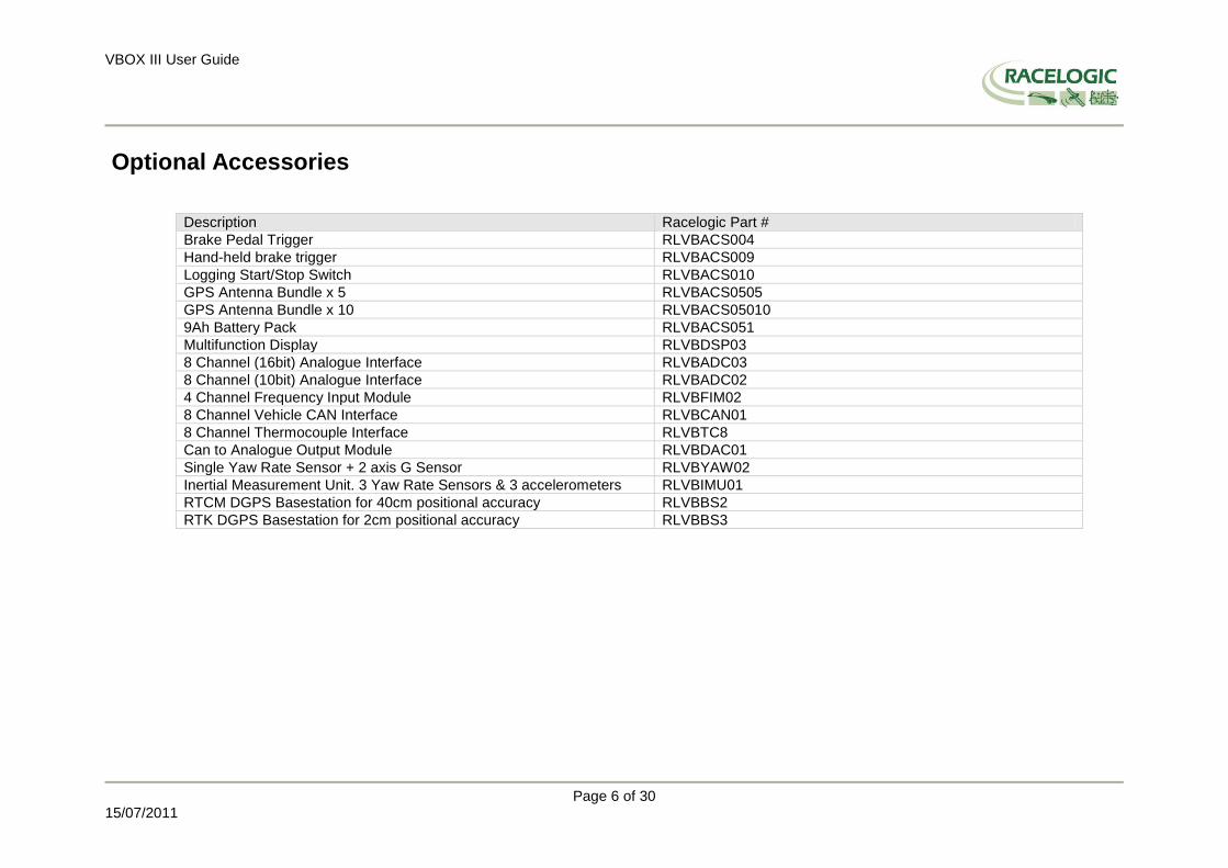
Optional Accessories
Description Racelogic Part #
Brake Pedal Trigger RLVBACS004
Hand-held brake trigger RLVBACS009
Logging Start/Stop Switch RLVBACS010
GPS Antenna Bundle x 5 RLVBACS0505
GPS Antenna Bundle x 10 RLVBACS05010
9Ah Battery Pack RLVBACS051
Multifunction Display RLVBDSP03
8 Channel (16bit) Analogue Interface RLVBADC03
8 Channel (10bit) Analogue Interface RLVBADC02
4 Channel Frequency Input Module RLVBFIM02
8 Channel Vehicle CAN Interface RLVBCAN01
8 Channel Thermocouple Interface RLVBTC8
Can to Analogue Output Module RLVBDAC01
Single Yaw Rate Sensor + 2 axis G Sensor RLVBYAW02
Inertial Measurement Unit. 3 Yaw Rate Sensors & 3 accelerometers RLVBIMU01
RTCM DGPS Basestation for 40cm positional accuracy RLVBBS2
RTK DGPS Basestation for 2cm positional accuracy RLVBBS3

VBOX III User Guide
Page 7 of 30
15/07/2011
Operation
Power
The VBOX III can be powered from a wide range of voltage sources including the Vehicle Cigar adapter, an optional Ni-Mh battery pack or other source provided by the user. The maximum operating voltage input must not exceed 30V DC. Failure to observe this could result in damage to the VBOX.
Warning
The VBOX can be connected to other Racelogic input modules including the ADC03, ADC02, TC8, FIM02 and Multifunction display. Please note that the voltage supply to Racelogic modules connected to the VBOX will be at the same level as the VBOX power input. Therefore when using any of the Racelogic peripherals with VBOX III, the input voltage must not exceed 15 volts. Failure to observe this could result in damage to the module and possibly the VBOX III
When running the VBOX from the rechargeable battery pack, the VBOX will sound a warning tone to indicate when the battery voltage is reaching the minimum operating voltage level. When this tone is heard, the battery pack requires re-charging. The usable battery life, when used with a VBOXIII alone, is in excess of 2Hrs. Please also note that during extended use, the VBOX III case may become hot. This is normal, however it is good practice to mount the VBOX III in a position where it has sufficient airflow around the case.
Buttons
The VBOX III has two membrane buttons on the front panel, LOG and FUNC. LOG is used to start and stop logging to the compact flash card, and FUNC is used to switch between two sample rates, 100Hz and 20Hz. Logging The LOG button will override any of the automatic logging thresholds set in the VBOX. For example, if you have set the VBOX to log all the time, the LOG button will toggle logging on and off. If you have set the VBOX to ‟log only when moving‟ and you are moving, pressing the LOG button will stop the VBOX logging and close the file on the compact flash. Logging will now not continue even if you are moving until the LOG button is pressed again or the compact flash card is removed and reinserted. The VBOX will then continue to log only when moving. Every time the logging is toggled with the LOG button, a new file is created. When the VBOX is logging, the blue CF light flashes. Do not remove the CF card or power down whilst this LED is flashing, if you need to remove the card or power down whilst the CF light is flashing, then press the LOG button first to stop the VBOX logging.

VBOX III User Guide
Page 8 of 30
15/07/2011
Sample rate Pressing the FUNC button briefly flashes the LED‟s to indicate the current sample rate. A slow flash (once per second) on all the LED‟s indicates 20Hz, and rapid flashing (5 times a second) indicates a 100Hz sample rate. A running sequence of lights indicates a sample rate other than 100Hz or 20Hz. Pressing and holding the FUNC button for 5 seconds toggles the current sample rate. The sample rate can also be set in the VBOX software. Default setup The default factory settings are restored to the VBOX by pressing and holding the FUNC button, and then at the same time pressing and holding the LOG button for 5 seconds. This will put the VBOX III into the default factory settings, 100Hz logging when moving, and the standard logging parameters : sats, time, latitude, longitude, velocity, heading, height, vertical velocity, and brake trigger event time. (DGPS will be off by default.).
LED indicators
There are 3 LED indicators on the front panel of the VBOX. The first LED, PWR, indicates that the VBOX is powered correctly. The SAT LED is used to indicate the number of GPS satellites that the VBOX has in lock. When no satellites are in lock, the SAT LED flashes slowly to indicate that the VBOX is searching for satellites. When one or more satellites are in lock, the LED will pulse the satellite count repeatedly with a short delay. The following diagram shows an example of SAT LED pulse sequence. Sequence showing 1 Satellite
1 1 1 1 Sequence showing 4 Satellites
Delay 1 2 3 4 Delay 1 2 3 4 Sequence showing 0 Satellites
Delay (Approximately 1 second ) Delay (Approximately 1 second )
VBOX III User Guide
Page 9 of 30
15/07/2011
Memory Cards
The VBOX III can accept Type-I compact flash memory cards. The memory cards must be formatted using FAT or FAT16 but not FAT32. This option is normally selectable when formatting the memory card in a card reader connected to a PC. When logging data to compact flash the blue CF LED will flash or be constantly illuminated. It is important not to remove the flash card while the blue LED is illuminated. If the card is removed while the VBOX is writing data to it, there is a risk that the data file may be corrupted resulting in loss of data. To remove the compact flash card while the VBOX is writing data, press the LOG button on the front panel of the VBOX and wait for the blue LED to turn OFF. When a compact Flash card is inserted or removed while powered, the VBOX will re-initialise. This will reset any temporary parameters held in the VBOX. For example, the CAN Bus parameter Distance from power-on will be reset to zero. Note: The VBOXIII can log upto 32 CAN channels in addition to the standard GPS channels. This is limited to 16 CAN channels when the Kalman Filter is enabled
GPS Antenna
The GPS Antenna supplied with the VBOX III is a 5v active antenna. For the best possible signal quality, it is important to maintain a clean connection between the antenna and the VBOX. Before fixing the antenna to the VBOX, ensure that there are no dust particles in either connector. Replacement antennas are available by contacting your VBOX distributor.
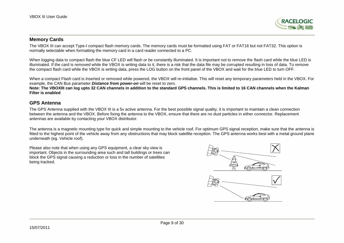
The antenna is a magnetic mounting type for quick and simple mounting to the vehicle roof. For optimum GPS signal reception, make sure that the antenna is fitted to the highest point of the vehicle away from any obstructions that may block satellite reception. The GPS antenna works best with a metal ground plane underneath (eg. Vehicle roof). Please also note that when using any GPS equipment, a clear sky view is important. Objects in the surrounding area such and tall buildings or trees can block the GPS signal causing a reduction or loss in the number of satellites being tracked.
VBOX III User Guide
Page 10 of 30
15/07/2011
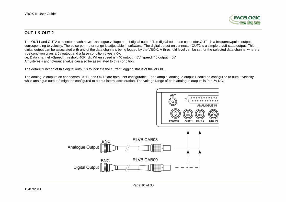
OUT 1 & OUT 2 The OUT1 and OUT2 connectors each have 1 analogue voltage and 1 digital output. The digital output on connector OUT1 is a frequency/pulse output corresponding to velocity. The pulse per meter range is adjustable in software. The digital output on connector OUT2 is a simple on/off state output. This digital output can be associated with any of the data channels being logged by the VBOX. A threshold level can be set for the selected data channel where a true condition gives a 5v output and a false condition gives a 0v. i.e. Data channel –Speed, threshold 40Km/h. When speed is >40 output = 5V, speed ,40 output = 0V A hysteresis and tolerance value can also be associated to this condition. The default function of this digital output is to indicate the current logging status of the VBOX. The analogue outputs on connectors OUT1 and OUT2 are both user configurable. For example, analogue output 1 could be configured to output velocity while analogue output 2 might be configured to output lateral acceleration. The voltage range of both analogue outputs is 0 to 5v DC.

VBOX III User Guide
Page 11 of 30
15/07/2011
Digital Inputs The DIG IN connector contains the two digital inputs for the VBOX III. Digital input 1 is also referred to as the Brake trigger input. This input is connected to an internal timer capture module that is able to record precisely an event time for use in brake distance calculation. This period of time is called the trigger event time, and is logged as the value in milliseconds between the trigger event and the last GPS sample. A hand-held brake trigger is also available to allow the user to record marker events in the VBOX III data file. A remote logging on/off switch is also available for ease of use and when the front panel switch is not accessible.

VBOX III User Guide
Page 12 of 30
15/07/2011
CAN / RS232 Ports The VBOX III is equipped with 2 CAN Bus interfaces and 2 RS232 serial ports. The primary RS232 port is used for all communication between the VBOX and laptop PC. The primary port is marked RS232 on the VBOX III front panel. The primary RS232 port is able to transmit live data from the VBOX to the PC for viewing and performing real-time tests. It is important to note however that due to limitations of the PC serial port, live data transfer is limited to 20Hz. Therefore for maximum accuracy, tests performed at a GPS sample rate above 20Hz should be logged to compact flash and post processed. The secondary RS232 port is used for connection to a Telemetry Radio module allowing the reception of Differential GPS (DGPS) data for local correction from a Racelogic Local DGPS basestation. The secondary RS232 port is located in the connector marked CAN on the VBOX III front panel. The CAN Bus ports A and B are located in the VBOX III connectors “CAN” and “RS232” respectively. The function of these ports is configurable by the user for use by either Racelogic external modules or the users own CAN Bus equipment. For dual use of RS232 and CAN from one of the sockets you will require a 5Way Lemo splitter RLVBACS024. Power supplied to external Racelogic CAN modules through the “CAN” or “RS232” cables is at the same voltage as the input power supply. Therefore when using Racelogic external CAN modules (eg; MFD or ADC03), the VBOX III supply voltage must not exceed 15vDC.

VBOX III User Guide
Page 13 of 30
15/07/2011
CAN / RS232 Ports (continued) The VBOX III can log up to 8 user defined CAN bus signals on CAN port B. Configuration is performed using the VCI Modules tab under Log Channels in the VBOX.EXE setup window. CAN signal parameters can be entered manually by the user or imported directly from a CAN database (.DBC) file if available.

VBOX III User Guide
Page 14 of 30
15/07/2011
Analogue inputs The VBOX III contains four differential 24bit analogue input channels with a maximum sample rate of 100Hz. Each channel has its own dedicated analogue to digital (A/D) converter with all four channels being sampled synchronously to each other. The voltage range of the input channels is ±50volts. Note that unlike the ADC03 module, the analogue channels in the VBOX III are not electrically isolated from each other. The analogue input connector also contains voltage outputs that can be used to power external sensors. These are a Vbatt connection which is equal to the VBOX input voltage level and a DC isolated 5 V Out connection which is equal to 5V ±2%. Both Vbatt and 5V Out connections are internally protected by 100mA thermal fuses. For connector pin configuration see page 16. A screw-terminal connector block is available as an option for easy connection of signal pins.
Example connection of resistive type sensor using isolated 5v supply Example connection of sensor with built-in regulator
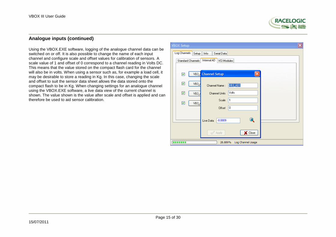
Using the VBOX.EXE software, logging of the analogue channel data can be switched on or off. It is also possible to change the name of each input channel and configure scale and offset values for calibration of sensors. A scale value of 1 and offset of 0 correspond to a channel reading in Volts DC. This means that the value stored on the compact flash card for the channel will also be in volts. When using a sensor such as a load cell, it may be desirable to store a reading in Kg. In this case, changing the scale and offset to suit the sensor data sheet allows the data stored onto the compact flash to be in Kg. When changing settings for an analogue channel using the VBOX.EXE software, a live data view of the current channel is shown. The value shown is the value after scale and offset is applied and can therefore be used to aid sensor calibration.
VBOX III User Guide
Page 15 of 30
15/07/2011
Analogue inputs (continued)
Using the VBOX.EXE software, logging of the analogue channel data can be switched on or off. It is also possible to change the name of each input channel and configure scale and offset values for calibration of sensors. A scale value of 1 and offset of 0 correspond to a channel reading in Volts DC. This means that the value stored on the compact flash card for the channel will also be in volts. When using a sensor such as, for example a load cell, it may be desirable to store a reading in Kg. In this case, changing the scale and offset to suit the sensor data sheet allows the data stored onto the compact flash to be in Kg. When changing settings for an analogue channel using the VBOX.EXE software, a live data view of the current channel is shown. The value shown is the value after scale and offset is applied and can therefore be used to aid sensor calibration.

VBOX III User Guide
Page 16 of 30
15/07/2011
Getting Started Required equipment (All supplied as standard unless specified)
VBOX III Fully charged battery pack or Cigar lighter 12v adapter lead GPS Antenna Blank Compact Flash Card RS232 Cable VBOX Software CD Laptop PC(not supplied)
1.Install Software
2.Place VBOX in vehicle
3.Fit antenna connector to VBOX
4. Mount GPS antenna on vehicle roof
5.Connect serial cable (CAB01) to laptop
6. Connect other end of serial cable to VBOX
VBOX III User Guide
Page 17 of 30
15/07/2011
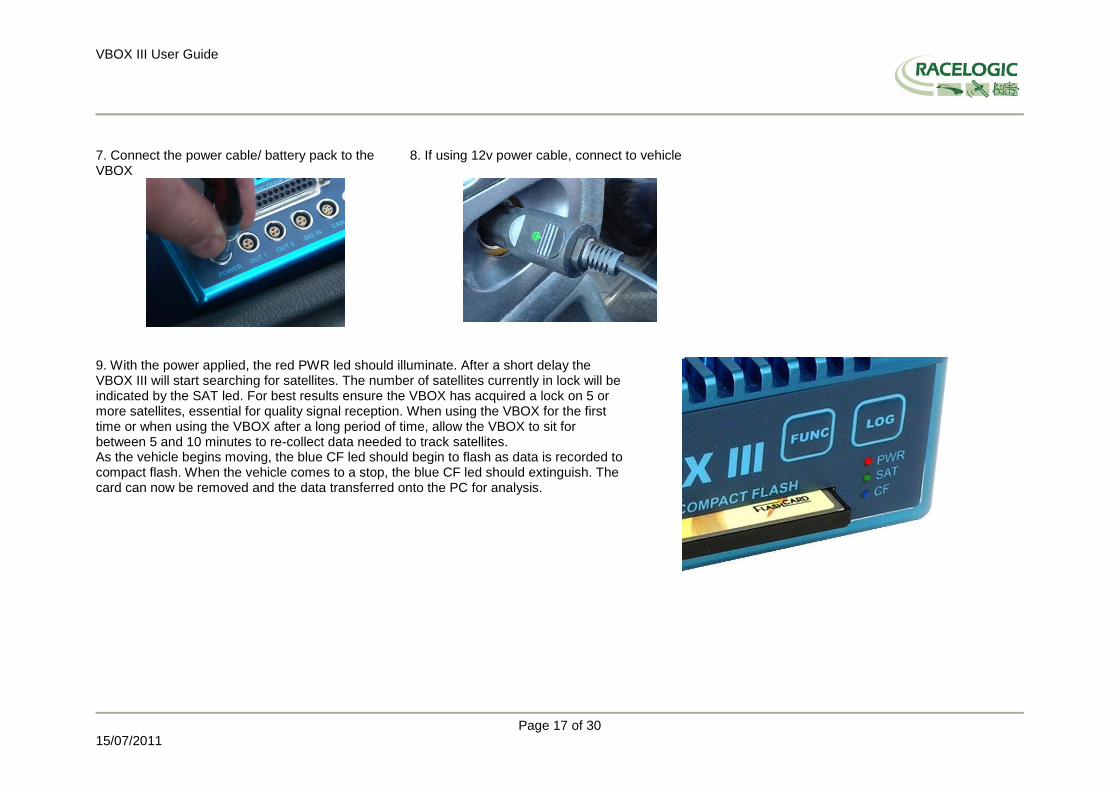
7. Connect the power cable/ battery pack to the VBOX
8. If using 12v power cable, connect to vehicle
9. With the power applied, the red PWR led should illuminate. After a short delay the VBOX III will start searching for satellites. The number of satellites currently in lock will be indicated by the SAT led. For best results ensure the VBOX has acquired a lock on 5 or more satellites, essential for quality signal reception. When using the VBOX for the first time or when using the VBOX after a long period of time, allow the VBOX to sit for between 5 and 10 minutes to re-collect data needed to track satellites. As the vehicle begins moving, the blue CF led should begin to flash as data is recorded to compact flash. When the vehicle comes to a stop, the blue CF led should extinguish. The card can now be removed and the data transferred onto the PC for analysis.

VBOX III User Guide
Page 18 of 30
15/07/2011
VBOX III ‘.VBO’ file format The VBOX III data files are saved in standard space de-limited text format. This allows the data to easily be imported into third party applications such as word processors or spreadsheets. The files each contain a header section before the main data that describes the channel content and information about the VBOXIII such as serial number and firmware version. The [Column names] parameter specifies the data in each column of the data section. An example of a VBOX VBO file is shown on the right.
File created on 15/04/2004 @ 08:21 [header] satellites time latitude longitude velocity knots heading height Vertical velocity m/s Event 1 time [channel units] [comments] I2001 – 2004 Racelogic Vbox3 V01.00 Build 0424 GPS Firmware : 2.4O January 13 2004 Serial Number : 00030005 Log Rate (Hz) : 100.00 [column names] sats time lat long velocity heading height vert-vel event-1 [data] 004 072148.26 +3119.408424 +00062.635139 015.13 356.06 +00155.27 –00000.22 0.00000 004 072148.27 +3119.408592 +00062.635104 015.17 356.02 +00147.93 –00000.37 0.00000 004 072148.28 +3119.408629 +00062.635108 015.09 355.92 +00147.92 –00000.40 0.00000 004 072148.29 +3119.408669 +00062.635115 014.98 355.64 +00147.92 –00000.35 0.00000 004 072148.30 +3119.408711 +00062.635119 015.00 355.87 +00147.91 –00000.47 0.00000 004 072148.31 +3119.408753 +00062.635122 015.03 356.11 +00147.90 –00000.61 0.00000 004 072148.32 +3119.408797 +00062.635125 015.16 356.48 +00147.88 –00000.84 0.00000 004 072148.33 +3119.408837 +00062.635130 015.06 356.32 +00147.88 –00000.67 0.00000 004 072148.34 +3119.408874 +00062.635138 014.84 355.81 +00147.91 –00000.14 0.00000 004 072148.35 +3119.408919 +00062.635144 015.03 355.84 +00147.90 –00000.28 0.00000 004 072148.36 +3119.408968 +00062.635147 015.42 356.17 +00147.87 –00000.66 0.00000 004 072148.37 +3119.409013 +00062.635148 015.56 356.72 +00147.87 –00000.69 0.00000

VBOX III User Guide
Page 19 of 30
15/07/2011
VBOXTools Software The VBOXTools software is used for configuration of the VBOX III and also for analysis of the VBO data files. For further information on the VBOXTools software refer to the VBOXTools user manual supplied with VBOX III.

VBOX III User Guide
Page 20 of 30
15/07/2011
Local DGPS Basestation When the VBOXIII is used in conjunction with a Local DGPS Basestation the positional accuracy can be improved from the standard 3m 95% CEP. There are two available Basestation options: 40cm Positional accuracy: If the VBOXIII is used with a RLVBBS2 then the positional accuracy is increased to 40cm 95% CEP. The height accuracy is improved to 1M 95%CEP 2cm Positional accuracy: If the VBOXIII has an RTK upgrade option installed and is used with a RLVBBS3 then the positional accuracy is increased to 2cm. Note: When the VBOX is used in RTK mode the maximum log rate is 50Hz. In RTK mode the VBOXIII must be used in open environments with no trees or buildings within at least 50M of the test track, or the accurate RTK mode will dropout and take up to 3 minutes to regain RTK lock.
Enabling the DGPS modes.
The VBOX must have the correct DGPS mode enabled in software before it is capable of receiving and using the DGPS correction information transmitted by a Local Basestation.
Run the latest VBOXTools software
Enter the VBOX setup screen and go to the GPS page
Click on the DGPS button and select the correct DGPS mode from the available option
Close the VBOXsetup screen. A live window can be created and set to the standard channel „DGPS‟. Then when the DGPS correction information is received from the Local Basestation the live window will display „ON‟.

VBOX III User Guide
Page 21 of 30
15/07/2011
Troubleshooting Guide Trouble Locking onto Satellites If the VBOX 3 is having trouble locking onto satellites then please follow the checklist below for typical solutions:
Ensure that the antenna is placed in a position where it has an unobstructed view of the sky. (See „GPS Antenna Placement‟ below)
Check the antenna connection with the VBOX 3; only small amounts of dirt in the socket can cause a significant reduction in signal strength. Also check the cable at the plug and along its length for any damage.
Check that the power supply is connected and free from damage.
If possible try another known working antenna, to confirm antenna functionality.
Perform a GPS Coldstart and then leave the unit powered up in an open static position for at least 15 minutes. See „VBOX 3 not responding‟ below. Once the VBOX 3 has locked on to 4 or more satellites it will be ready for use. No Communication with PC
If the red LED on the front of the VBOX 3 is not illuminated then there is no power to the unit; check that battery contains adequate charge or, if using a cigar lighter, check internal cigar lighter fuse.
Check that the correct COM port has been selected in VBOXTools
Check that no other programs are using the same COM port.
Disconnect the power to the VBOX 3 then reconnect it. COM Port Unavailable
The computer may have been started with a different VBOX 3 connected to it; disconnect the VBOX 3, restart the computer then reconnect the VBOX3.
Another software package installed on your computer may have reserved the COM port. No Data is logged to the VBO file
Check satellite reception. Loss of reception may prevent data from being logged to the card (dependent on logging mode).

VBOX III User Guide
Page 22 of 30
15/07/2011
VBOX 3 not responding - GPS Coldstart
The GPS engine has locked up.
Perform a GPS Engine Coldstart A GPS coldstart forces the GPS engine to reset its downloaded almanac of current satellite positions. This can be useful if the VBOX 3 is having trouble locking onto satellites, which typically occurs if the VBOX 3 has not been used for several weeks or if it was last used a long distance (over one thousand miles) away from the current location. After performing a GPS coldstart leave the VBOX 3 powered up in a static location where the antenna has an unobstructed view of the skies until the „GPS‟ LED becomes solid green. Once the VBOX 3 has downloaded the new almanac it will reacquire satellites in noisy situations (such as near trees, buildings and under bridges) much more quickly. It will also acquire satellite much more quickly on power-up.
To perform a GPS coldstart on the VBOX 3 perform the following actions:
Press and hold the „LOG‟ button on the front of the VBOX 3 for five seconds until a long beep is sounded.
When the button is released the „GPS‟ LED will start to flash red showing that the Coldstart has been performed and the GPS engine is now not locked onto any satellites.
After approximately 30-45 secs the „GPS‟ LED will start to flash green indicating that satellite lock has been achieved and indicating the number of satellites that it is locked onto.
Firmware Upgrades Firmware refers to the operating software inside the VBOX III. The firmware is responsible for all of the functions within the VBOX and from time to time, firmware updates will be released by Racelogic to improve or enhance the way that the VBOX works. The latest firmware will always be available on the Racelogic web site in the downloads directory:-
http://www.racelogic.co.uk/2003/vbox/downloads.htm It is recommended to check the web site periodically for updates. The VBOX III upgrade files have a “.UPG” file extension. To upgrade the VBOX III firmware, download the latest firmware file from the Racelogic web site and copy this file onto a compact flash card. Then insert the compact flash card into the VBOX III. Apply power to the VBOX. All three LEDs on the front panel should illuminate. After a short period of time, the green and blue LEDs on the front panel will flash. When the LEDs stop flashing the VBOX will re-initialise and begin normal operation. This will be indicated by the green SAT LED flashing slowly as the VBOX searches for satellites. After upgrade, the UPG file will be deleted from the flash card and an upgrade log file will have been created. This log file can be emailed to the support address below should any problems arise. If you have any questions regarding upgrade of VBOX, please do not hesitate to contact [email protected]
VBOX III User Guide
Page 23 of 30
15/07/2011
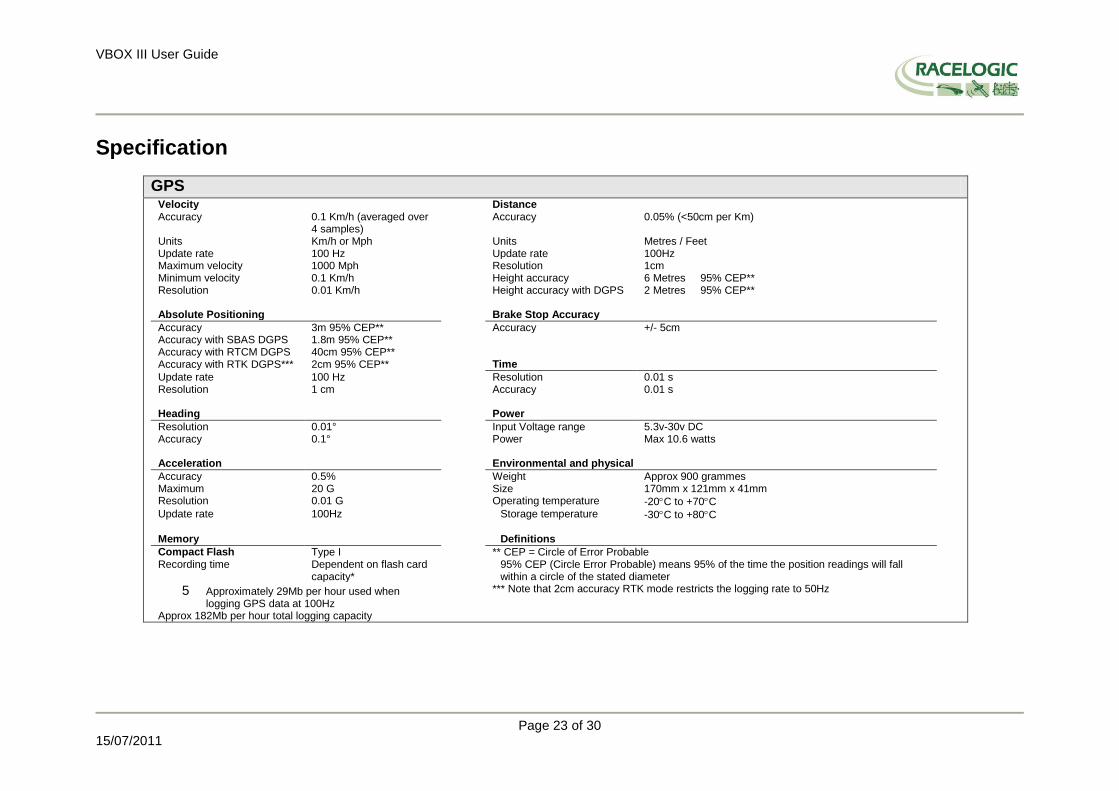
Specification
GPS Velocity Distance Accuracy 0.1 Km/h (averaged over
4 samples) Accuracy 0.05% (<50cm per Km)
Units Km/h or Mph Units Metres / Feet Update rate 100 Hz Update rate 100Hz Maximum velocity 1000 Mph Resolution 1cm Minimum velocity 0.1 Km/h Height accuracy 6 Metres 95% CEP** Resolution 0.01 Km/h Height accuracy with DGPS 2 Metres 95% CEP** Absolute Positioning Brake Stop Accuracy
Accuracy 3m 95% CEP** Accuracy +/- 5cm Accuracy with SBAS DGPS 1.8m 95% CEP** Accuracy with RTCM DGPS 40cm 95% CEP** Accuracy with RTK DGPS*** 2cm 95% CEP** Time
Update rate 100 Hz Resolution 0.01 s Resolution 1 cm Accuracy 0.01 s Heading Power
Resolution 0.01° Input Voltage range 5.3v-30v DC Accuracy 0.1° Power Max 10.6 watts Acceleration Environmental and physical
Accuracy 0.5% Weight Approx 900 grammes Maximum 20 G Size 170mm x 121mm x 41mm Resolution 0.01 G Operating temperature -20C to +70C Update rate 100Hz Storage temperature -30C to +80C Memory Definitions
Compact Flash Recording time
Type I Dependent on flash card capacity*
** CEP = Circle of Error Probable 95% CEP (Circle Error Probable) means 95% of the time the position readings will fall within a circle of the stated diameter
5 Approximately 29Mb per hour used when logging GPS data at 100Hz
Approx 182Mb per hour total logging capacity
*** Note that 2cm accuracy RTK mode restricts the logging rate to 50Hz

VBOX III User Guide
Page 24 of 30
15/07/2011
Outputs
CAN Bus Bit rate 250Kbits ,500Kbits &
1Mbit selectable baud rate
Identifier type Standard 11bit 2.0A Data available Satellites in View, Latitude, Longitude, Velocity, Heading, Altitude, Vertical velocity, Distance, Longitudinal acceleration & lateral
acceleration, Distance from trigger, Trigger time, trigger Velocity Analogue Digital
Voltage range 0 to 5Volts DC Frequency range DC to 44.4Khz Default setting * Velocity
0.0125Volts per Km/h (0 to 400Km/h)
Default setting * 25Hz per Km/h (0 to 400Km/h)
Accuracy 0.1 Km/h 90 pulses per metre Update rate 100Hz Accuracy 0.1Km/h Update rate 100Hz
* The range settings can be adjusted by the user in software
Inputs CAN Bus
Racelogic modules Up to 32 channels from any combination of ADC02, ADC03, FIM02, TC8, Yaw sensor or CAN01. Limited to 16 with the Kalman Filter enabled
External CAN Bus 8 Channels of user definable CAN signal from external bus. Eg; vehicle CAN bus
Can load signal data from industry standard DBC database file. Analogue
Number Channels 4 Resolution 24 bit Input range ±50v DC Accuracy 400 μV Channel Sample order Synchronous Digital
Brake/Event Trigger Selectable signal polarity. 16bit timer capture with12μs resolution On/Off Logging control Remote log control from hand-held switch

VBOX III User Guide
Page 25 of 30
15/07/2011
Connection Data
Front View of VBOX III
2 pin LEMO socket
3 pin LEMO socket
5 pin LEMO socket
Connector 1 POWER Type Lemo 2 pin
PIN In/Out Description Range
1 I Power + 5.4V to 30V
2 I Ground 0V
Connector 2 OUT 1 Type Lemo 3 pin
PIN In/Out Description Range
1 O Analogue 1 Output 0V to 5V
2 O Digital 2 Output 0V to 5V
3 I Ground

VBOX III User Guide
Page 26 of 30
15/07/2011
Connector 3 OUT 2 Type Lemo 3 pin
PIN In/Out Description Range
1 O Analogue 2 Output 0V to 5V
2 O Digital 1 Output 0V to 5V
3 I
Connector 4 DIG IN Type Lemo 3 pin
PIN In/Out Description Range
1 I Ground
2 I Digital Input 2. Start/Stop Logging 0V to 5V (14v tolerant)
3 I Digital Input 1. Brake Trigger 0V to 5V (14v tolerant)
Connector 5 CAN Bus Type Lemo 5 pin
PIN In/Out Description Range
1 O RS232 Tx (PORT B) 12v
2 I RS232 Rx (PORT B) 12v
3 I/O CAN Bus High (PORT A)
4 I/O CAN Bus Low (PORT A)
5 O +V Power Same as Power +
Connector 6 RS232 Type Lemo 5 pin
PIN In/Out Description Range
1 O RS232 Tx (PORT A) 12v
2 I RS232 Rx (PORT A) 12v
3 I/O CAN Bus High PORT B)
4 I/O CAN Bus Low (PORT B)
5 O +V Power Same as Power +

VBOX III User Guide
Page 27 of 30
15/07/2011
Antenna connector Connector ANT Type SMA
PIN In/Out Description Range
Center - RF Signal / Power for active antenna
Chassis - Ground

VBOX III User Guide
Page 28 of 30
15/07/2011
Analogue Input Connector
View of Socket on VBOX III
Connector: Analogue Type: Sub-D 25-way Socket Connector: Analogue Type: Sub-D 25-way Socket
PIN In/Out Description Range PIN In/Out Description Range
1 I Channel 1 + 14 O Vbatt Equal to Input Voltage. 100mA
2 I Channel 1 - 15 O GND
3 I Channel 2 + 16 O Iso. 5 V Out Isolated 5V ±2%. 100mA
4 I Channel 2 - 17 O Iso. GND Isolated Ground
5 I Channel 3 + 18
6 I Channel 3 - 19
7 I Channel 4 + 20
8 I Channel 4 - 21
9 22
10 23
11 24
12 25
13
Note: A screw terminal connector block is available to purchase on request from your VBOX supplier.

VBOX III User Guide
Page 29 of 30
15/07/2011
CAN Bus data format Format Motorola
ID** Update rate *
Data Bytes
1 2 3 4 5 6 7 8
0x301 10ms (1) Sats in view
(2) Time since midnight UTC (3) Position – Latitude MMMM.MMMMM
0x302 10ms (4) Position – Longitude MMMMM.MMMMM (5) Velocity. (Knots) (6) Heading. (Degrees)
0x303 10ms (7) Altitude. WGS 84. (Metres) (8) Vertical velocity. (M/S) Unused (9) Status (10) Status
0x304 10ms (11) Distance. (Meters) (12) Longitudinal Accel. (G) (13) Lateral Accel. (G)
0x305 10ms (14) Distance travelled since VBOX reset (15) Trigger time (16) Trigger Velocity
0x306 10ms (17) Velocity Quality Unused Unused Unused
*Update rate depends on GPS update rate. 10ms Update rate shown corresponds to 100Hz GPS setting. **Default Identifiers. The identifier values can be changed using the configuration software.
(1) If Satellites in view < 3 then only Identifier 0x301 transmitted and bytes 2 to 8 are set to 0x00. (2) Time since midnight. This is a count of 10mS intervals since midnight UTC. (5383690 = 53836.90 seconds since midnight or 14 hours, 57 minutes and 16.90 seconds) (3) Position, Latitude * 100,000 (311924579 = 51 Degrees, 59.24579 Minutes North). This is a true 32bit signed integer, North being positive. (4) Position, Longitude * 100,000 (11882246 = 1 Degrees, 58.82246 Minutes West). This is a true 32bit signed integer, West being positive. (5) Velocity, 0.01 knots per bit.
(6) Heading, 0.01 per bit. (7) Altitude, 0.01 meters per bit, signed. (8) Vertical Velocity, 0.01 m/s per bit, signed. (9) Status. 8 bit unsigned char. Bit 0=VBOX Lite, Bit 1=Open or Closed CAN Bus (1=open), 2=VBOX3 (10) Status is an 8 bit unsigned char. Bit 0 is always set, Bit 3=brake test started, Bit 4 = Brake trigger active, Bit 5 = DGPS active (11) Distance, 0.000078125 meters per bit, unsigned. Corrected to trigger point. (12) Longitudinal Acceleration, 0.01G per bit, signed. (13) Lateral Acceleration, 0.01G per bit, signed. (14) Distance travelled in meters since VBOX reset. (15) Time from last brake trigger event. 0.01 Seconds per bit. (16) Velocity at brake trigger point in Knots. (17) Velocity Quality, 0.01 km/h per bit
The VBOX CAN database is available in Vector Database (DBC File) format on request from Racelogic

VBOX III User Guide
Page 30 of 30
15/07/2011
Contact Information Racelogic Ltd Unit 10 Swan Business Centre Osier Way Buckingham MK18 1TB UK Tel: +44 (0) 1280 823803 Fax: +44 (0) 1280 823595 Email : [email protected] Web : www.racelogic.co.uk
Revision Date Description Author
1 04/03/2004 First Draft CS
2 12/04/2004 Correction to connector information CS
3 02/06/2004 Additional voltage supply information CS
4 20/12/2004 Correction to analogue input diagram page 13 KB
5 06/01/2005 CAN Bus data correction KB
6 07/02/2005 CAN Bus data correction CS
7 10/03/2005 CAN Bus data correction KB
8 24/05/2006 Standard inventory section removed – Optional accessories updated RF
9 05/07/2006 Updates to reflect 2cm RTK DGPS mode and new VBOXTools software KB
10 05/12/2006 Addition of Velocity Quality to CAN format KB
11 20/12/2006 Information of Max no of Log channels clarified KB
12 05/06/2006 Inclusion of Declaration of Conformity Statement CAS
13 03/12/2007 Addition of Format: Motorola to CAN Bus Data Format table NT
14 11/02/2008 Correction of volt range to Brake trigger input KB
15 30/04/2008 Updated Racelogic contact information JH
16 24/11/2008 Addition of 2nd
digital output function KB
17 15/07/2011 Added „troubleshooting guide‟ copied from VB3i manual including coldstart information LN