Embed Size (px)
Citation preview
AD20 ABSORBANCE DETECTOROPERATOR’S MANUAL
© 1995 Dionex Corporation
Document No. 034853Revision 03April 1995
© 1995 by Dionex CorporationAll rights reserved worldwidePrinted in the United States of America
This publication is protected by federal copyright law. No part ofthis publication may be copied or distributed, transmitted,transcribed, stored in a retrieval system, or transmitted into anyhuman or computer language, in any form or by any means,electronic, mechanical, magnetic, manual, or otherwise, or disclosedto third parties without the express written permission of DionexCorporation, 1228 Titan Way, Sunnyvale, California 94088-3603U.S.A.
DISCLAIMER OF WARRANTY AND LIMITED WARRANTY
THIS PUBLICATION IS PROVIDED “AS IS” WITHOUTWARRANTY OF ANY KIND. DIONEX CORPORATION DOESNOT WARRANT, GUARANTEE, OR MAKE ANYPRESENTATIONS REGARDING THE USE, OR THE RESULTSOF THE USE, OF THIS PUBLICATION IN TERMS OFCORRECTNESS, ACCURACY, RELIABILITY,CURRENTNESS, OR OTHERWISE. FURTHER, DIONEXCORPORATION RESERVES THE RIGHT TO REVISE THISPUBLICATION AND TO MAKE CHANGES FROM TIME TOTIME IN THE CONTENT HEREINOF WITHOUTOBLIGATION OF DIONEX CORPORATION TO NOTIFY ANYPERSON OR ORGANIZATION OF SUCH REVISION ORCHANGES.
TRADEMARKS
DX LAN is a trademark of Dionex Corporation.Teflon® and Tefzel® are registered trademarks of E.I. du Pont deNemours & Co.
PRINTING HISTORY
Revision 01, August 1993Revision 02, September 1993Revision 03, April 1995
Contents
1 • Introduction
1.1 Overview . . . . . . . . . . . . . . . . . . . . . . . 1-3
1.2 About This Manual . . . . . . . . . . . . . . . . . 1-3
1.2.1 Typefaces . . . . . . . . . . . . . . . . . . 1-4
1.2.2 Safety Messages and Notes . . . . . . . . 1-4
1.2.3 Symbols . . . . . . . . . . . . . . . . . . . 1-5
1.3 Related Manuals . . . . . . . . . . . . . . . . . . . 1-6
2 • Description
2.1 Front Control Panel . . . . . . . . . . . . . . . . . 2-4
2.1.1 Control Panel Keypad . . . . . . . . . . . 2-5
2.2 Rear Panel . . . . . . . . . . . . . . . . . . . . . . 2-9
2.3 Electronics Chassis . . . . . . . . . . . . . . . . . 2-10
2.4 Optical Chassis . . . . . . . . . . . . . . . . . . . 2-13
2.4.1 Photodiode Assembly . . . . . . . . . . . 2-14
2.4.2 Flow Cells . . . . . . . . . . . . . . . . . 2-14
2.4.3 Heat Exchanger . . . . . . . . . . . . . . 2-15
2.4.4 Tungsten Lamp . . . . . . . . . . . . . . . 2-15
2.4.5 Deuterium Lamp . . . . . . . . . . . . . . 2-16
2.5 Functional Description . . . . . . . . . . . . . . . 2-17
2.5.1 Modes of Operation . . . . . . . . . . . . 2-17
2.5.2 Control . . . . . . . . . . . . . . . . . . . 2-19
2.6 Theory of Operation . . . . . . . . . . . . . . . . 2-21
Doc. 034853-03 4/95 Contents-1
3 • Operation and Maintenance
3.1 Operating Guidelines . . . . . . . . . . . . . . . . 3-3
3.1.1 Wavelength Selection . . . . . . . . . . . 3-3
3.1.2 Mobile Phases . . . . . . . . . . . . . . . 3-3
3.1.3 Solvent Delivery System . . . . . . . . . 3-4
3.2 Initial Screens . . . . . . . . . . . . . . . . . . . . 3-5
3.3 Running Under Direct Control . . . . . . . . . . . 3-7
3.4 Running Under Method Control . . . . . . . . . . 3-8
3.4.1 Creating a New Method . . . . . . . . . . 3-9
3.4.2 Editing an Existing Method . . . . . . . . 3-10
3.4.3 Running a Method . . . . . . . . . . . . . 3-12
3.4.4 Changing the Running Method . . . . . . 3-13
3.5 Controlling Another Instrument . . . . . . . . . . 3-13
3.6 DX LAN Remote Operation . . . . . . . . . . . . 3-13
3.7 Routine Maintenance . . . . . . . . . . . . . . . . 3-14
4 • Troubleshooting
4.1 No Detector Response . . . . . . . . . . . . . . . 4-3
4.2 Noisy Baseline . . . . . . . . . . . . . . . . . . . 4-4
4.3 Drifting Baseline . . . . . . . . . . . . . . . . . . 4-5
4.4 High Background Absorbance . . . . . . . . . . . 4-6
4.5 Peaks Too Large or Small . . . . . . . . . . . . . 4-7
4.6 Lamp Does Not Light . . . . . . . . . . . . . . . . 4-7
4.7 Detector Does Not Autozero . . . . . . . . . . . . 4-7
4.8 Cannot Calibrate Wavelength . . . . . . . . . . . 4-8
4.9 Faulty DX LAN Communication . . . . . . . . . 4-8
AD20 Absorbance Detector
Contents-2 Doc. 034853-03 4/95
4.10 Diagnostics . . . . . . . . . . . . . . . . . . . . . 4-9
5 • Service
5.1 Liquid Leaks . . . . . . . . . . . . . . . . . . . . . 5-3
5.2 Cleaning the Cell . . . . . . . . . . . . . . . . . . 5-3
5.3 Removing Trapped Air from the Cell . . . . . . . 5-4
5.4 Replacing the Main Power Fuses . . . . . . . . . 5-4
5.5 Replacing the Deuterium Lamp . . . . . . . . . . 5-6
5.6 Replacing the Tungsten Lamp . . . . . . . . . . . 5-7
A • Specifications
A.1 Electrical . . . . . . . . . . . . . . . . . . . . . . . A-3
A.2 Environmental . . . . . . . . . . . . . . . . . . . . A-3
A.3 Physical . . . . . . . . . . . . . . . . . . . . . . . A-3
A.4 Display and Keypad . . . . . . . . . . . . . . . . . A-3
A.5 Detector . . . . . . . . . . . . . . . . . . . . . . . A-4
A.6 Flow Cell . . . . . . . . . . . . . . . . . . . . . . A-5
A.7 Heat Exchanger . . . . . . . . . . . . . . . . . . . A-5
B • Installation
B.1 Facilities Required . . . . . . . . . . . . . . . . . B-3
B.2 System Configuration . . . . . . . . . . . . . . . . B-4
B.3 Unpacking . . . . . . . . . . . . . . . . . . . . . . B-5
B.4 Installation . . . . . . . . . . . . . . . . . . . . . . B-6
B.4.1 Power . . . . . . . . . . . . . . . . . . . . B-6
Contents
Doc. 034853-03 4/95 Contents-3

B.4.2 Flow Cell . . . . . . . . . . . . . . . . . . B-7
B.4.3 Heat Exchanger . . . . . . . . . . . . . . B-9
B.4.4 Waste Line . . . . . . . . . . . . . . . . . B-9
B.4.5 Detector Output . . . . . . . . . . . . . . B-9
B.4.6 Relay/TTL Control . . . . . . . . . . . . B-10
B.4.7 DX LAN Network Connection (Optional) B-12
C • User Interface
C.1 Operational Screens . . . . . . . . . . . . . . . . . C-4
C.1.1 Menu of Screens . . . . . . . . . . . . . . C-4
C.1.2 Main Screen . . . . . . . . . . . . . . . . C-5
C.1.3 Detail Screen . . . . . . . . . . . . . . . . C-7
C.1.4 Method . . . . . . . . . . . . . . . . . . . C-9
C.1.5 Module Setup Screen . . . . . . . . . . . C-11
C.1.6 Analog Output Setup . . . . . . . . . . . C-12
C.1.7 Time Function In . . . . . . . . . . . . . C-13
C.2 Diagnostic Screens . . . . . . . . . . . . . . . . . C-14
C.2.1 Diagnostic Menu . . . . . . . . . . . . . . C-14
C.2.2 Power-Up Screen . . . . . . . . . . . . . . C-15
C.2.3 Elapsed Time . . . . . . . . . . . . . . . . C-16
C.2.4 Analog Status . . . . . . . . . . . . . . . C-17
C.2.5 DX LAN Status . . . . . . . . . . . . . . C-19
C.2.6 Keyboard Test . . . . . . . . . . . . . . . C-21
C.2.7 Diagnostic Tests . . . . . . . . . . . . . . C-22
C.2.8 Leak Sensor Calibration and Status . . . C-25
C.2.9 Signal Statistics . . . . . . . . . . . . . . C-26
C.2.10 Offset Zero Calibration . . . . . . . . . . C-27
AD20 Absorbance Detector
Contents-4 Doc. 034853-03 4/95
D • Common Mobile Phases
D.1 Properties of Common Mobile Phases . . . . . . D-3
Contents
Doc. 034853-03 4/95 Contents-5

AD20 Absorbance Detector
Contents-6 Doc. 034853-03 4/95

1 • Introduction
1.1 Overview . . . . . . . . . . . . . . . . . . . . . . . 1-3
1.2 About This Manual . . . . . . . . . . . . . . . . . 1-3
1.2.1 Typefaces . . . . . . . . . . . . . . . . . . 1-4
1.2.2 Safety Messages and Notes . . . . . . . . 1-4
1.2.3 Symbols . . . . . . . . . . . . . . . . . . . 1-5
1.3 Related Manuals . . . . . . . . . . . . . . . . . . . 1-6
Doc. 034853-03 4/95 1-1

AD20 Absorbance Detector
1-2 Doc. 034853-03 4/95
1 • Introduction
1.1 Overview
The AD20 Absorbance Detector is a dual-beam, variable wavelengthphotometer. Full spectral capability is provided by two light sources:a deuterium lamp for ultraviolet detection and a tungsten lamp forvisible wavelength operation. The AD20 features programmablewavelength selection and automatic calibration for precision,reproducibility, and ease-of-use. The AD20 is designed for use witha variety of standard bore and microbore flow cells.
The AD20 can be controlled locally from the front panel, or from aremote host computer via the optional Dionex DX LAN interfaceand PeakNet Software.
1.2 About This Manual
Chapter 1, Introduction , provides a brief overview of the AD20Absorbance Detector. It also includes an explanation of the productsafety messages that appear throughout the manual.
Chapter 2, Description, describes physical aspects of the AD20,including front panel controls, electronics, and flow cells. This isfollowed by a description of the AD20 operating modes.
Chapter 3, Operation and Maintenance, discusses operatingfeatures and methods (how to create, edit, and run methods) anddescribes how absorbance detection is used. Routine preventivemaintenance requirements appear at the end of this chapter.
Chapter 4, Troubleshooting, lists possible causes of problems, alongwith step-by-step instructions to isolate and eliminate them.
Chapter 5, Service, presents step-by-step instructions for routineservice and parts replacement procedures.
Doc. 034853-03 4/95 1-3
Appendix A, Specifications, lists the detector specifications andfacility requirements.
Appendix B, Installation , describes the installation and interfacerequired to place the AD20 into operation. Also included are setupprocedures for operating the AD20 either in a stand-aloneenvironment or as a component of a chromatography system.
Appendix C, User Interface, describes the front panel display andcontrols in detail and includes illustrations of all menus and screensused for AD20 operation and diagnostics.
Appendix D, Common Eluents, lists the UV cutoff values (in nm)for selected absorbance eluents.
1.2.1 Typefaces
Typefaces are used in this manual as follows.
• Capitalized bold Helvetica indicates a front panel button:
Press Enter to begin running the method.
• Upper-case bold Helvetica indicates the name of a menuor screen; it may also indicate a field on a screen:
Go to the METHOD screen.
Move the cursor to the EDIT field.
1.2.2 Safety Messages and Notes
This instrument has been designed to comply with therequirements for safety set forth in IEC 1010 SafetyRequirements for Electrical Equipment for Measurement,Control, and Laboratory Use.
This manual contains warnings and precautionary statementsthat can prevent personal injury and/or damage to theinstrument when properly followed. Safety messages appearin bold type and are accompanied by icons.
AD20 Absorbance Detector
1-4 Doc. 034853-03 4/95
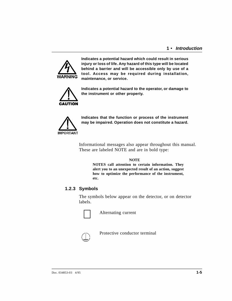
Indicates a potential hazard which could result in seriousinjury or loss of life. Any hazard of this type will be locatedbehind a barrier and will be accessible only by use of atool. Access may be required during installat ion,maintenance, or service.
Indicates a potential hazard to the operator, or damage tothe instrument or other property.
Indicates that the function or process of the instrumentmay be impaired. Operation does not constitute a hazard.
Informational messages also appear throughout this manual.These are labeled NOTE and are in bold type:
NOTENOTES call attention to certain information. Theyalert you to an unexpected result of an action, suggesthow to optimize the performance of the instrument,etc.
1.2.3 Symbols
The symbols below appear on the detector, or on detectorlabels.
Alternating current
Protective conductor terminal
∼
1 • Introduction
Doc. 034853-03 4/95 1-5
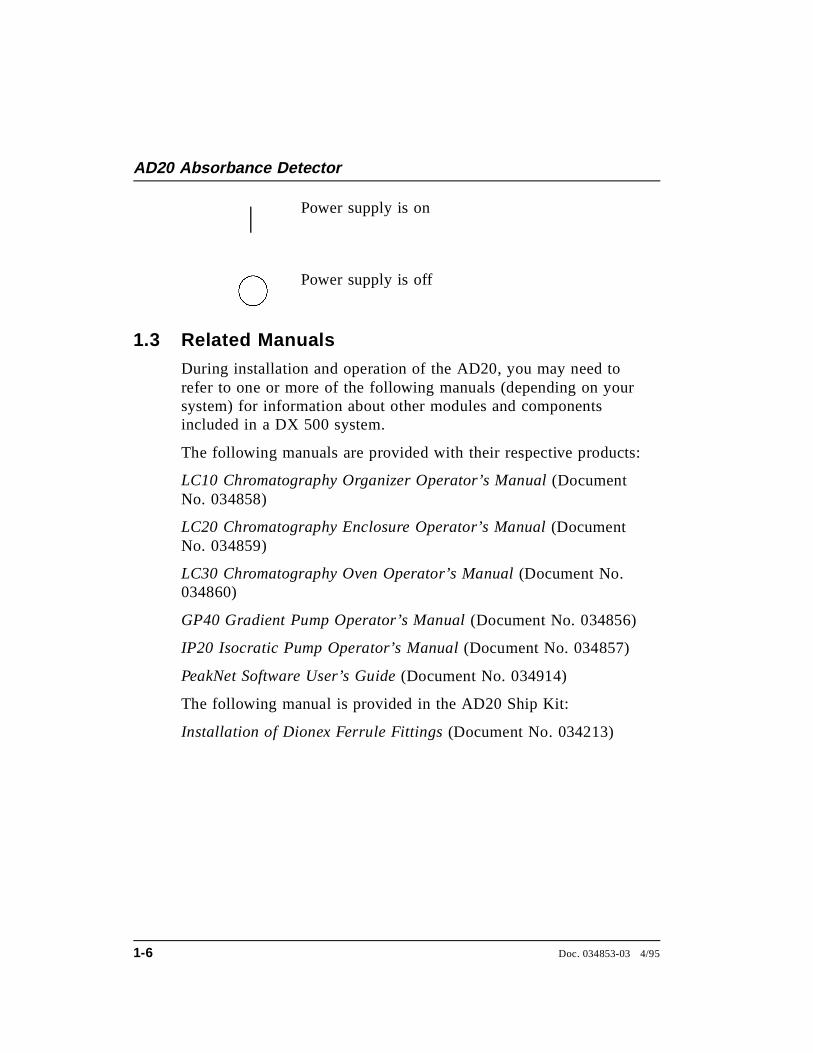
Power supply is on
Power supply is off
1.3 Related Manuals
During installation and operation of the AD20, you may need torefer to one or more of the following manuals (depending on yoursystem) for information about other modules and componentsincluded in a DX 500 system.
The following manuals are provided with their respective products:
LC10 Chromatography Organizer Operator’s Manual (DocumentNo. 034858)
LC20 Chromatography Enclosure Operator’s Manual (DocumentNo. 034859)
LC30 Chromatography Oven Operator’s Manual (Document No.034860)
GP40 Gradient Pump Operator’s Manual (Document No. 034856)
IP20 Isocratic Pump Operator’s Manual (Document No. 034857)
PeakNet Software User’s Guide (Document No. 034914)
The following manual is provided in the AD20 Ship Kit:
Installation of Dionex Ferrule Fittings (Document No. 034213)
AD20 Absorbance Detector
1-6 Doc. 034853-03 4/95

2 • Description
2.1 Front Control Panel . . . . . . . . . . . . . . . . . 2-4
Screen Contrast . . . . . . . . . . . . . . . 2-4
Tilt Panel . . . . . . . . . . . . . . . . . . 2-4
Power Switches . . . . . . . . . . . . . . 2-4
2.1.1 Control Panel Keypad . . . . . . . . . . . 2-5
2.2 Rear Panel . . . . . . . . . . . . . . . . . . . . . . 2-9
Power Entry . . . . . . . . . . . . . . . . 2-9
Fuses . . . . . . . . . . . . . . . . . . . . 2-10
DX LAN Connection (Optional) . . . . . 2-10
2.3 Electronics Chassis . . . . . . . . . . . . . . . . . 2-10
Power Supply Card . . . . . . . . . . . . 2-11
PIO (Power) Card . . . . . . . . . . . . . 2-12
SP1 (Signal Processing) Card . . . . . . . 2-12
Blank Card . . . . . . . . . . . . . . . . . 2-12
Relay/DX LAN and CPU Cards . . . . . 2-13
2.4 Optical Chassis . . . . . . . . . . . . . . . . . . . 2-13
Leak Management . . . . . . . . . . . . . 2-14
2.4.1 Photodiode Assembly . . . . . . . . . . . 2-14
2.4.2 Flow Cells . . . . . . . . . . . . . . . . . 2-14
2.4.3 Heat Exchanger . . . . . . . . . . . . . . 2-15
2.4.4 Tungsten Lamp . . . . . . . . . . . . . . . 2-15
2.4.5 Deuterium Lamp . . . . . . . . . . . . . . 2-16
2.5 Functional Description . . . . . . . . . . . . . . . 2-17
2.5.1 Modes of Operation . . . . . . . . . . . . 2-17
Local Mode . . . . . . . . . . . . . . . . . 2-17
Remote Mode . . . . . . . . . . . . . . . . 2-18
Doc. 034853-03 4/95 2-1
2.5.2 Control . . . . . . . . . . . . . . . . . . . 2-19
Direct control . . . . . . . . . . . . . . . . 2-19
Method control . . . . . . . . . . . . . . . 2-19
AD20 Absorbance Detector
2-2 Doc. 034853-03 4/95
2 • Description
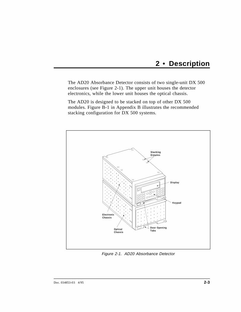
The AD20 Absorbance Detector consists of two single-unit DX 500enclosures (see Figure 2-1). The upper unit houses the detectorelectronics, while the lower unit houses the optical chassis.
The AD20 is designed to be stacked on top of other DX 500modules. Figure B-1 in Appendix B illustrates the recommendedstacking configuration for DX 500 systems.
ElectronicChassis
Op ticalChassis
Stackin gDim p les
Dis p la y
Ke yp ad
Door O p enin gTabs
Figure 2-1. AD20 Absorbance Detector
Doc. 034853-03 4/95 2-3
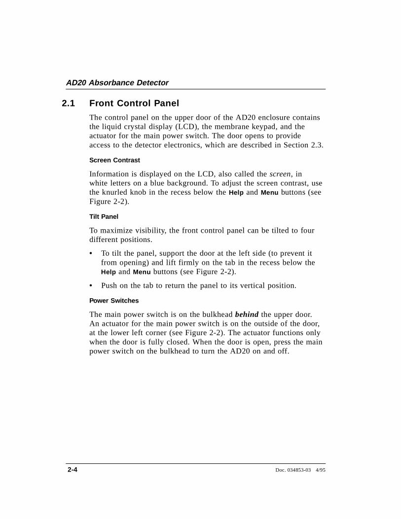
2.1 Front Control Panel
The control panel on the upper door of the AD20 enclosure containsthe liquid crystal display (LCD), the membrane keypad, and theactuator for the main power switch. The door opens to provideaccess to the detector electronics, which are described in Section 2.3.
Screen Contrast
Information is displayed on the LCD, also called the screen, inwhite letters on a blue background. To adjust the screen contrast, usethe knurled knob in the recess below the Help and Menu buttons (seeFigure 2-2).
Tilt Panel
To maximize visibility, the front control panel can be tilted to fourdifferent positions.
• To tilt the panel, support the door at the left side (to prevent itfrom opening) and lift firmly on the tab in the recess below theHelp and Menu buttons (see Figure 2-2).
• Push on the tab to return the panel to its vertical position.
Power Switches
The main power switch is on the bulkhead behind the upper door.An actuator for the main power switch is on the outside of the door,at the lower left corner (see Figure 2-2). The actuator functions onlywhen the door is fully closed. When the door is open, press the mainpower switch on the bulkhead to turn the AD20 on and off.
AD20 Absorbance Detector
2-4 Doc. 034853-03 4/95
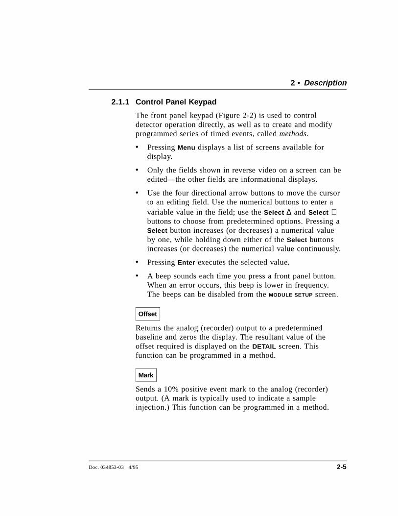
2.1.1 Control Panel Keypad
The front panel keypad (Figure 2-2) is used to controldetector operation directly, as well as to create and modifyprogrammed series of timed events, called methods.
• Pressing Menu displays a list of screens available fordisplay.
• Only the fields shown in reverse video on a screen can beedited—the other fields are informational displays.
• Use the four directional arrow buttons to move the cursorto an editing field. Use the numerical buttons to enter avariable value in the field; use the Select ∆ and Select ∇buttons to choose from predetermined options. Pressing aSelect button increases (or decreases) a numerical valueby one, while holding down either of the Select buttonsincreases (or decreases) the numerical value continuously.
• Pressing Enter executes the selected value.
• A beep sounds each time you press a front panel button.When an error occurs, this beep is lower in frequency.The beeps can be disabled from the MODULE SETUP screen.
Offset
Returns the analog (recorder) output to a predeterminedbaseline and zeros the display. The resultant value of theoffset required is displayed on the DETAIL screen. Thisfunction can be programmed in a method.
Mark
Sends a 10% positive event mark to the analog (recorder)output. (A mark is typically used to indicate a sampleinjection.) This function can be programmed in a method.
2 • Description
Doc. 034853-03 4/95 2-5

Insert
Inserts a new step into a method. Move the cursor to the TIMEfield and press Insert to add a new step after the cursorposition. The parameter fields in the new step will be blank.Enter a time value for the new step and press Enter . (If youmove the cursor to a different field before entering the time,the new step is incomplete and will disappear.)
Insert steps in any order; after you press Enter , the steps willbe automatically organized in the correct chronological order.
AD20 Absorbance Detector
Hold /Run
1
0
2 3
4 5 6
7 8 9
Enter
Offset
M a r k Reset
Insert Se lec t
Dele te Se lec t
He lp M e n u
Tab ( for openin gthe door)
Tab (for t i l t in g the panel)
Knob ( for ad j ust in gthe contrast)
Ma in PowerSwi tch Actuator
He lp Message
MENU of SCREENS
1234
MAIN SCREENDETAIL SCREENM E T H O D___
5678
MODULE SETUPANALOG OUT SETUPTIME FUNCTION INDIAGNOSTIC MENU
Figure 2-2. AD20 Front Panel
AD20 Absorbance Detector
2-6 Doc. 034853-03 4/95
Delete
Removes the value from the current entry field, allowingentry of a new value. To restore the previous value, move thecursor from the field without entering a new value.
On the METHOD screen, pressing Delete when the cursor is ina step entry field “blanks” the step parameter value. Whenyou move the cursor from the field, the field remains blank(i.e., the previous value is not restored, as it is on otherscreens). Blank step fields indicate that there is no changefrom the previous step.
To use Delete to delete an entire method step:
1. Position the cursor in the method’s time field and pressDelete . The time is removed and the help line displays thismessage:
TO DELETE THIS STEP, PRESS DELETE AGAIN
2. To delete the entire step, press Delete again. If you do notwant to delete the step, press any button except Delete andthe original time and step parameters will be restored.
Hold/Run
Turns the method clock off (Hold ) and on (Run) . This buttonfunctions only when the detector is under Method control(see Section 2.5.2).
When the method clock is in Hold, pressing Hold/Run startsthe clock. The clock starts at the initial step of a new methodor, if resuming an interrupted method, at the time at whichthe clock was put in Hold.
When the method clock is in Run, pressing Hold/Run stopsthe method clock, thereby “holding” the method and freezingthe current conditions.
2 • Description
Doc. 034853-03 4/95 2-7
Reset
Changes the method clock time to INIT, causing the initialconditions specified by the method to occur. This buttonfunctions only when the detector is under Method control(see Section 2.5.2).
If the method is running, it continues running. If the methodis in Hold, the method clock executes the initial conditionsand holds.
Select ∆ and Select ∇
When the cursor is positioned at a field with predeterminedparameters, these buttons cycle through the options. In fieldswhich have predetermined numerical values, pressing Select ∆increases the value by one unit, while pressing Select ∇decreases the value by one unit. Holding down one of theSelect buttons increases (or decreases) the value continuously.Press Enter to place the new value into effect.
←, ↑, →, and ↓
The four cursor directional buttons move the cursor, in thedirection of the arrow, to the next entry field. If there is nochangeable field in that direction, the cursor movesdiagonally or remains where it is.
Help
Displays a help screen with information pertaining to thecurrent entry field.
Menu
From any operational screen, pressing Menu displays theMENU of SCREENS . From any diagnostic screen, pressingMenu once returns you to the DIAGNOSTIC MENU; pressingMenu again returns you to the MENU of SCREENS .
AD20 Absorbance Detector
2-8 Doc. 034853-03 4/95
Numeric Buttons
Enters numeric values into the current entry field. Thenumeric buttons are 0 through 9 and the decimal.
Enter
Saves and/or executes changes made in entry fields. Afterpressing Enter , the cursor moves back to the left margin ofthe same field. It does not automatically move to the nextfield.
On menu screens, pressing Enter displays the highlightedscreen.
On the METHOD screen, pressing Enter does not save changesto method parameters. To save editing changes, move thecursor to the SAVE TO field, enter the method number, andpress Enter .
2.2 Rear Panel
The AD20 rear panel (Figure B-3) contains fuses, connectors for linepower, and the optional DX LAN connector.
Power Entry
The power entry, fusing, and EMI filter are mounted on the rear ofthe 150 watt power supply module. The power entry is socketed fora modular power cord (IEC 320 C13). The detector requires agrounded, single-phase power source. The detector may be operatedfrom 85 to 270 Vac, 47 to 63 Hz power. The input power is 150 wattmaximum. The line voltage is automatically selected and requires noadjustments.
SHOCK HAZARD—If a grounded receptacle is not used,a shock hazard may result. Do not operate or connect toAC power mains without earthed ground connections.
2 • Description
Doc. 034853-03 4/95 2-9
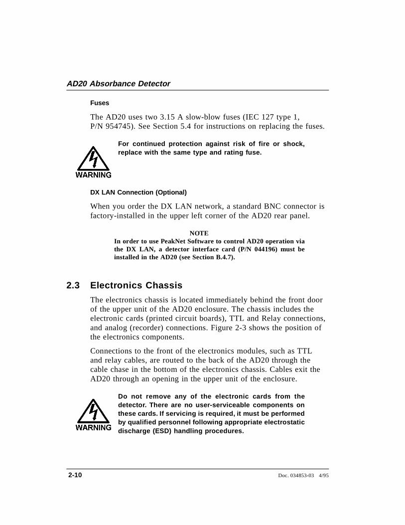
Fuses
The AD20 uses two 3.15 A slow-blow fuses (IEC 127 type 1,P/N 954745). See Section 5.4 for instructions on replacing the fuses.
For continued protection against risk of fire or shock,replace with the same type and rating fuse.
DX LAN Connection (Optional)
When you order the DX LAN network, a standard BNC connector isfactory-installed in the upper left corner of the AD20 rear panel.
NOTEIn order to use PeakNet Software to control AD20 operation viathe DX LAN, a detector interface card (P/N 044196) must beinstalled in the AD20 (see Section B.4.7).
2.3 Electronics Chassis
The electronics chassis is located immediately behind the front doorof the upper unit of the AD20 enclosure. The chassis includes theelectronic cards (printed circuit boards), TTL and Relay connections,and analog (recorder) connections. Figure 2-3 shows the position ofthe electronics components.
Connections to the front of the electronics modules, such as TTLand relay cables, are routed to the back of the AD20 through thecable chase in the bottom of the electronics chassis. Cables exit theAD20 through an opening in the upper unit of the enclosure.
Do not remove any of the electronic cards from thedetector. There are no user-serviceable components onthese cards. If servicing is required, it must be performedby qualified personnel following appropriate electrostaticdischarge (ESD) handling procedures.
AD20 Absorbance Detector
2-10 Doc. 034853-03 4/95
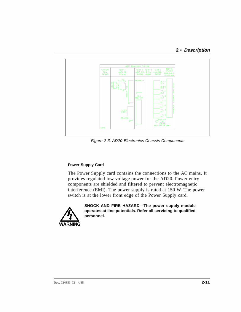
Power Supply Card
The Power Supply card contains the connections to the AC mains. Itprovides regulated low voltage power for the AD20. Power entrycomponents are shielded and filtered to prevent electromagneticinterference (EMI). The power supply is rated at 150 W. The powerswitch is at the lower front edge of the Power Supply card.
SHOCK AND FIRE HAZARD—The power supply moduleoperates at line potentials. Refer all servicing to qualifiedpersonnel.
Figure 2-3. AD20 Electronics Chassis Components
2 • Description
Doc. 034853-03 4/95 2-11

PIO (Power) Card
The PIO card controls the deuterium and tungsten lamps, the gratingdrive motor, and the filter/shutter wheel. It also supplies power tothe optical unit cooling fans.
SHOCK HAZARD—Components used for the deuteriumlamp ignition and operation are at high potentials. Referall servicing to qualified personnel.
SP1 (Signal Processing) Card
The SP1 card provides the signal processing used when absorbanceis measured. A pre-amp in the optical chassis is connected to theSP1 card via a 25-pin D sub-miniature connector and a ribbon cable.The photodiode outputs are amplified for subsequent log ratioconversion to absorbance by the pre-amp. The gain of the pre-amp isvariable to compensate for the lamp output and other systemvariables. The pre-amp does not require calibration.
The 3-pin connector at the top of the SP1 card is the analog(recorder) output. The output scale, polarity, baseline offset, andfilter rise time can be set from the ANALOG OUT SETUP screen.
Blank Card
The slot next to the SP1 card contains a blank card. This cardcompletes the electromagnetic interference (EMI) shielding.
AD20 Absorbance Detector
2-12 Doc. 034853-03 4/95
Relay/DX LAN and CPU Cards
The AD20 control Moduleware and BIOS reside on the CPU logicand Relay I/O cards in slot 5 of the card cage. The Relay card ridespiggyback on the CPU card and extends over the front of slot 4.
A 60-pin ribbon cable assembly links the CPU logic to the frontpanel display and keypad. The CPU logic monitors the internalpower supply outputs. The multicolor LED at the bottom of slot 4indicates the status of the power supply:
• A green LED indicates normal operation.
• A red or yellow LED indicates a power fault. If a power faultoccurs, the AD20 enters its diagnostic state and no other controlis permitted until the fault is corrected.
The Relay card is short enough to allow an optional DX LANdetector interface card (P/N 044196) to be mounted behind it in slot4. If you have a PeakNet Workstation, you can downloadModuleware updates from PeakNet Software.
2.4 Optical Chassis
The optical chassis is located immediately behind the front door ofthe lower unit of the AD20 enclosure. The chassis contains theoptical hardware, flow cell, and photodiode assembly. The opticalbench and cooling components are mounted in a drawer. The drawerslides out of the enclosure to permit routine servicing withoutbreaking down the system.
The drawer is on a track with detent stops. To open the drawer, liftthe grip handle at the front of the drawer to clear the first detent. Asecond detent stops the drawer when it is halfway out.
Do not open the optical chassis drawer past the seconddetent.
2 • Description
Doc. 034853-03 4/95 2-13
Leak Management
Because the flow cell is behind the detector front door, liquid leaksmay not be detected immediately. To prevent damage to detectorcomponents, a leak tray is built into the bottom of the opticalchassis. A sensor in the sump of the leak tray responds to changes inthermal dissipation when wet and triggers an alarm in the detector.If the AD20 is connected to a PeakNet Workstation via the DX LANinterface, an alarm signal is sent to PeakNet Software.
Tubing connected to the rear of the leak tray directs leaks into awaste container. Check periodically to verify that the drain tube isnot clogged and that it is routed below the leak tray.
2.4.1 Photodiode Assembly
The photodiode assembly is mounted directly on the cell andbeamsplitter, allowing a variety of flow cell options (seeSection 2.4.2). The signal cable connects to the pre-ampbehind the bulkhead panel.
2.4.2 Flow Cells
Flow cells, which are ordered separately from the AD20, areavailable in the following path lengths and volumes:
• Standard bore—10 mm path, 9 µL volume, PEEK
• Narrow bore—6 mm path, 7.5 µL volume, PEEK
• Microbore—3 mm path, 2.5 µL volume, PEEK
The cell may be operated at pressures up to 3.45 mPa(500 psi) if operated without the heat exchanger. See Section2.4.3 for more information about the heat exchanger.
Do not use a PEEK cell with applications em ploying normalphase or chlorinated solvents; these solvents will damagethe cell.
AD20 Absorbance Detector
2-14 Doc. 034853-03 4/95

2.4.3 Heat Exchanger
The heat exchanger is a knitted coil that smooths the baselineduring trace-level analyses by minimizing fluctuations in celland flow stream temperature that cause drift and noise.
The heat exchanger is mounted just below the flow cell. Theappropriate heat exchanger is included with the flow cell.
Description Volume Materials
Standard bore 10 µL Tefzel, PEEKMicrobore 2 µL Tefzel, PEEK
Do not operate the heat exchanger at backpressuresgreater than 1.38 mPa (200 psi). For applications thatrequire extremely low dead volume, or have very highbackpressure after the detector, you may bypass the heatexchanger.
The heat exchanger contains indium (In) alloy. If the heatexchanger is ever damaged, dispose of it in accordance withlocal laws.
2.4.4 Tungsten Lamp
The tungsten lamp (P/N 047426) is a halogen lamp thatprovides high quality visible and near-UV performance. Atthe low power setting, the lamp provides good visible andnear-IR performance.
The lamp is socketed on a detachable mount at the right rearof the optical chassis. Replacement lamps are pre-aligned tothe detachable mount. The tungsten lamp has a service life of1000 hours when routinely operated at high power, or 5000hours when routinely operated at low power.
The lamp housing may be hot to the touch, especiallywhen the lamp has been operating on high. Allow5 minutes for the lamp housing to cool before handling.
2 • Description
Doc. 034853-03 4/95 2-15
2.4.5 Deuterium Lamp
The deuterium lamp (P/N 045230) is sealed in a pre-alignedmount and is clamped to the side of the monochromator. Analignment pin in the optical chassis registers the position ofthe lamp assembly for simple replacement.
The deuterium lamp has a service life of 1000 hours whenroutinely operated at high power, or 2000 hours whenroutinely operated at low power.
The lamp housing may be hot to the touch, especiallywhen the lamp has been operating on high. Allow5 minutes for the lamp housing to cool before handling.
AD20 Absorbance Detector
2-16 Doc. 034853-03 4/95
2.5 Functional Description
This section discusses the AD20 Absorbance Detector functionaloperation, including operating modes and types of control.
2.5.1 Modes of Operation
The AD20 has two operating modes: Local and Remote.When the detector is powered up, it is always in Local. Tochange the operating mode, go to either the MAIN or DETAILscreen. There, move the cursor to the LOCAL field and use theSelect ∆ or Select ∇ button to toggle the mode. Press Enterwhen the mode is correctly selected. When you selectREMOTE, you will be prompted to confirm the selection.
Local Mode
Local mode allows two types of commands:
• Direct entry onto a screen, using the front panel buttons
• TTL and Relay inputs
TTL functions are defined from the TIME FUNCTION INscreen. TTL logic levels can control any four of these AD20functions:
• OFFSET
• HOLD/RUN
• LAMP OFF/ON (for both lamps)
• METHOD NUMBER INCR
• METHOD NUMBER DECR
• MARK Recorder
• Increase RANGEX10
This allows control of the AD20 via a remote controller orthe timed event function of an integrator. The remainingfunctions are controlled from the AD20 front panel buttons.
2 • Description
Doc. 034853-03 4/95 2-17
You may configure input TTL logic levels as normal edge,inverted edge, normal pulse, or inverted pulse. No specialsetup or switch is required for TTL control, which is alwaysavailable in Local mode. Front panel control remains active.
Remote Mode
NOTEFor more information about Remote control of the detector, referto the PeakNet Software User’s Guide.
In Remote mode, the AD20 is computer-controlled throughPeakNet Software and the DX LAN interface. Select theRemote mode from the MAIN or DETAIL screen, or fromPeakNet.
There are two forms of Remote control: Remote and LockedRemote. While operating in normal Remote mode, all buttonson the AD20 front panel function except Hold/Run . Enter canbe used to select display functions that do not interfere withDX LAN remote control of a method while it is running.
The Locked Remote mode locks out all parameter changesfrom the AD20 front panel. Locked Remote can be selectedonly from the computer and can be cleared only from thecomputer or by turning off the AD20 power. When the AD20is powered up again, it will be in Local mode.
If you select the Remote mode while the AD20 is running amethod, the computer will not interrupt the method unlessyou select the Abort command from PeakNet Software.
After PeakNet downloads a method to the AD20, thecomputer activates the method number with a DX LANcommand. The INITial conditions step is activated. If amethod is already running when the computer activates amethod number, that method will be interrupted and thedetector method clock will reset to INITial conditions.
AD20 Absorbance Detector
2-18 Doc. 034853-03 4/95
A subsequent Run command will cause the AD20 methodclock to run, activating the timed event starting with the time0.00 step of the method.
2.5.2 Control
There are two types of control in either Local or Remotemode: Direct control and Method control.
Direct Control
In Direct control, commands are executed as soon as they areentered. Since there is no time-based program, the methodclock is not used. The Hold/Run and Reset buttons are notoperable in Direct control.
To select Direct control, first go to either the MAIN or DETAILscreen. If DIRECT CNTRL is displayed, the mode is alreadyselected and no further action is necessary. If METHOD isdisplayed, move the cursor to METHOD and press the Select ∆or Select ∇ button to toggle between DIRECT CNTRL andMETHOD in the display. Press Enter to activate the selection.
If a method is running when you select Direct control, thatmethod is aborted and the method clock is reset.
Method Control
In Method control, commands are executed as programmed ina given method. The parameters below are method-controlledand cannot be changed from the AD20 front panel:
• Analog range
• Offset
• Mark
• Wavelength
• Lamp settings
• Relays and TTLs
2 • Description
Doc. 034853-03 4/95 2-19
There are three ways to change a method-controlledparameter:
• Edit the currently running method and save the changes.The changes will be implemented when the method issaved.
• Switch to a different method.
• Abort the method, go to Direct control, and enter the newparameters directly.
Methods are programmed and controlled from the METHOD
screen. Besides storing and running methods, the AD20allows you to run the detector under Method control whileyou are are editing any method, even one that is currentlyrunning.
When saving changes to the currently running method orswitching to a different method, the method clock continuesrunning unaffected. Only those parameter changes whichaffect the method after the current time will be implementedin the current run. Of course, you may intentionally pressReset to implement the initial conditions.
You may enter non-method programmed parameters from thefront panel, as well as display screens to monitor detectoroperation.
To select Method control while in Direct control, go to eitherthe MAIN or DETAIL screen. Move the cursor to the DIRECTCNTRL field, press either Select button, and press Enter .METHOD will replace DIRECT CNTRL in the display.
Each method can contain up to 32 separate time-based steps,starting at time zero (TIME = 0). A method is created by firstselecting a method number from 0 through 99. The steps arethen entered one-by-one by entering first the time and thenwhatever operating parameters you want to be in effect at thattime.
AD20 Absorbance Detector
2-20 Doc. 034853-03 4/95
Methods are retained in memory even after the detectorpower is turned off. Up to 100 methods (00 through 99) canbe stored in AD20 memory. The actual total depends on thesize of each method and the amount of available memory andis usually less than 100.
2.6 Theory of Operation
Photometric detection is based on the absorption of monochromaticlight. The degree of absorption depends on the sample molecule, itsconcentration, the sample path length, and the wavelength.
The definition of absorbance is Beer-Lambert’s Law:
A = ε c l = log10 (Ir
Is) and is dimensionless
where:
ε = molar absorptivity of the sample (L • mol-1 • cm-1)c = concentration (mol/L)l = cell path length (cm)I r = reference beam intensityIs = sample beam intensity
Detection can be made by direct native absorption of a chromophorein the sample, or by indirect and post-column reactions. For a list ofwavelengths for the absorption maxima of various chromophores, seeAppendix D.
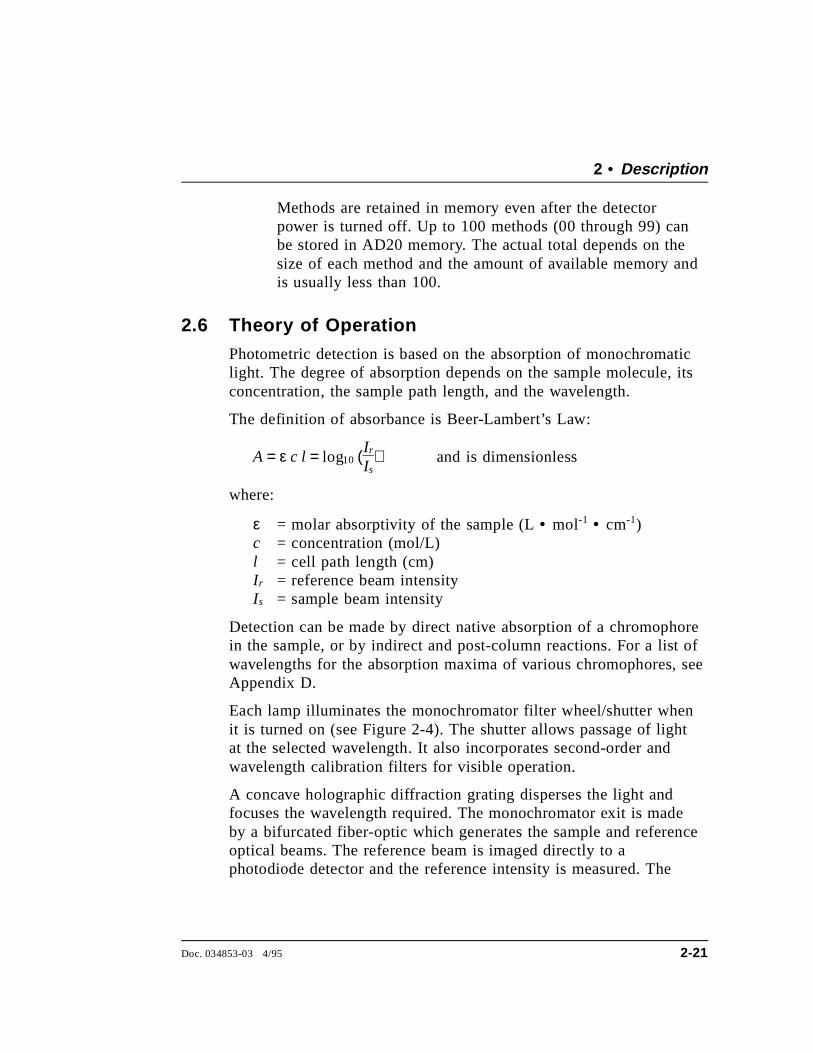
Each lamp illuminates the monochromator filter wheel/shutter whenit is turned on (see Figure 2-4). The shutter allows passage of lightat the selected wavelength. It also incorporates second-order andwavelength calibration filters for visible operation.
A concave holographic diffraction grating disperses the light andfocuses the wavelength required. The monochromator exit is madeby a bifurcated fiber-optic which generates the sample and referenceoptical beams. The reference beam is imaged directly to aphotodiode detector and the reference intensity is measured. The
2 • Description
Doc. 034853-03 4/95 2-21
sample beam is imaged to the flow cell, and the resultant sampleintensity is measured. Absorbance measurement is completed by thepre-amp and the SP1 electronics.
NOTEAn excellent reference for the principles used to take the bestadvantage of photometric detection is the text BiologicalSpectroscopy by Ian D. Campbell and Raymond A. Dwek,published by The Benjamin/Cummings Publishing Company,Inc. (ISBN 0-8053-1849-6).
Figure 2-4. Optical System
AD20 Absorbance Detector
2-22 Doc. 034853-03 4/95
3 • Operation and Maintenance
3.1 Operating Guidelines . . . . . . . . . . . . . . . . 3-3
3.1.1 Wavelength Selection . . . . . . . . . . . 3-3
3.1.2 Mobile Phases . . . . . . . . . . . . . . . 3-3
3.1.3 Solvent Delivery System . . . . . . . . . 3-4
3.2 Initial Screens . . . . . . . . . . . . . . . . . . . . 3-5
Power-Up Test . . . . . . . . . . . . . . . 3-5
Power-Up Screen . . . . . . . . . . . . . . 3-6
Diagnostic Tests Screen . . . . . . . . . . 3-6
Main Screen . . . . . . . . . . . . . . . . 3-7
3.3 Running Under Direct Control . . . . . . . . . . . 3-7
3.4 Running Under Method Control . . . . . . . . . . 3-8
3.4.1 Creating a New Method . . . . . . . . . . 3-8
3.4.2 Editing an Existing Method . . . . . . . . 3-10
Changing Method Parameters . . . . . . . 3-11
Adding a Method Step . . . . . . . . . . . 3-11
Deleting a Method Step . . . . . . . . . . 3-11
Deleting an Entire Method . . . . . . . . 3-11
Saving a Modified Method . . . . . . . . 3-12
3.4.3 Running a Method . . . . . . . . . . . . . 3-12
3.4.4 Changing the Running Method . . . . . . 3-13
3.5 Controlling Another Instrument . . . . . . . . . . 3-13
3.6 DX LAN Remote Operation . . . . . . . . . . . . 3-13
3.7 Routine Maintenance . . . . . . . . . . . . . . . . 3-14
Doc. 034853-03 4/95 3-1

AD20 Absorbance Detector
3-2 Doc. 034853-03 4/95
3 • Operation and Maintenance
3.1 Operating Guidelines
3.1.1 Wavelength Selection
There are two major criteria for determining the wavelengthfor an analysis:
• Sample components should absorb strongly at the selectedwavelength.
• The mobile phase should be “transparent,” showing littleor no absorption, at the selected wavelength.
For a list of wavelengths for the absorption maxima ofvarious chromophores, refer to Appendix D.
3.1.2 Mobile Phases
Solvent quality significantly affects detection limits andinstrument performance. To ensure optimal performance ofthe AD20 Absorbance Detector, follow these precautions:
• Prepare all mobile phases with spectroscopy-gradesolvents, reagent-grade chemicals, and ASTM Type I (orbetter) filtered deionized water.
• Degas all mobile phases before use and maintain them ina degassed state.
• Strong bases will etch silica. If the mobile phase is a baseand the flow cell windows are silica, the mobile phaseconcentration should not exceed 0.1 M. If theconcentration of the base is greater than 50 mM,disconnect the separator column and flush the system withdeionized water for 5 minutes at 1.0 mL/min immediatelyafter the analysis.
Doc. 034853-03 4/95 3-3
• Mobile phase pH affects not only the retention time of theseparation, but the absorbance of the sample and thebackground absorbance of the mobile phase. If an analysisemploys chemical suppression and compound detectiontechniques, compare the UV cutoff of the eluent beforeand after the suppressor to see whether it is better tolocate the detector ahead of the suppressor. This locationalso limits suppressor exposure to backpressure.
• When changing from a buffer to a different operatingmobile phase, be sure the solvents are miscible and willnot induce precipitation of the buffers. Flush the cell withdeionized water immediately after the analysis. Do notallow buffers to remain in the cell for extended periods.
3.1.3 Solvent Delivery System
The pumping system should deliver continuous flow whilemaintaining a consistent mobile phase composition (ifgradient elution is used). For trace- level detection, flow rateirregularities should not cause backpressure variations greaterthan 10% of baseline pressure. Most pumps are capable ofachieving this level of performance, or can be made to do soby the addition of a pulse damper.
The plastics or rubber that are present in some solventdelivery systems are not fully compatible with operation ofthe AD20 at UV wavelengths, or with the solvents commonlyused in reversed phase chromatography. For UV operation,these guidelines are recommended:
• The mobile phase reservoir should be glass, as theplasticizers used in blow-molded components will leachand are strong UV absorbers.
• All tubing connections should be Teflon®, Tefzel®,PEEK, PFA, stainless steel, or titanium as required for theoperating pressures and application.
AD20 Absorbance Detector
3-4 Doc. 034853-03 4/95
• Pump seals incorporate a band spring to energize the sealduring the vacuum stroke of the piston. The energizershould be stainless steel, a fluoropolymer (Kalrez orfluorosilicone), or other material of known quality.Solvent contact with EPR or Buna rubbers is incompatiblewith UV operation.
Cleanliness is also important. After operating in detectionmodes that do not require optically clean reagents (e.g.,conductivity), the solvent delivery system may need to bethoroughly cleaned. Some basic cleaning steps are listedbelow; for additional information, refer to the pump manual.
• Passivate stainless steel systems before the initial analysis,if the system has lost passivation, or after a majordisassembly. For instructions, see Passivation of StainlessSteel Systems and Components (Document No. 031152).
• Remove non-polar oils and dirt with a dilute soap orsurfactant such as sodium dodecylsulfate (SDS), Alconox,or SNOOP. Hot deionized water can also be helpful. Tocompletely remove surfactants, flush the system withdilute methanol or acetone.
• Depending on the polarity of the contaminant, flush thesystem with acetonitrile or 10% tetrahydrofuran.
• If the system has been contaminated by a precipitate, youmay need to flush the system with a strong acid or base.
3.2 Initial Screens
Power-Up Tests
Each time the AD20 power is turned on, the detector runs aseries of internal diagnostic and wavelength calibrationprocedures. During the self-diagnostics, the power supplies,CPU, lamps, filter wheel position, DX LAN communications,SP1 signal processing status, and grating initialization arechecked and the visible and UV wavelength are recalibrated.
3 • Operation and Maintenance
Doc. 034853-03 4/95 3-5
As each phase is executed, the test name and result appear onthe screen.
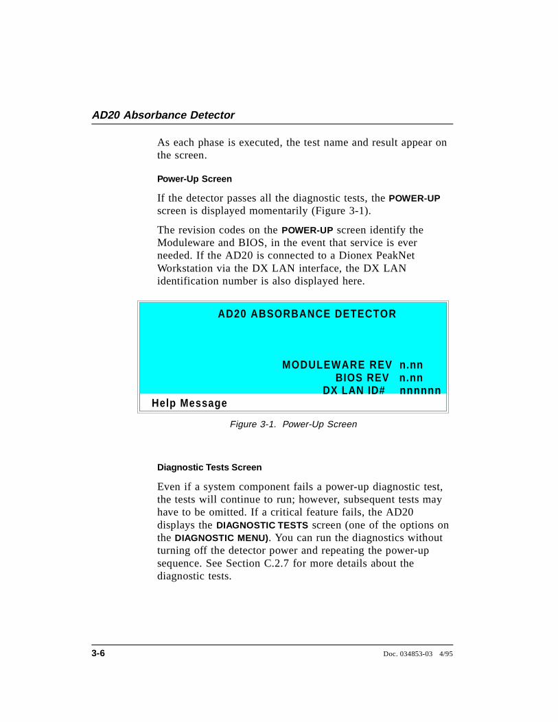
Power-Up Screen
If the detector passes all the diagnostic tests, the POWER-UPscreen is displayed momentarily (Figure 3-1).
The revision codes on the POWER-UP screen identify theModuleware and BIOS, in the event that service is everneeded. If the AD20 is connected to a Dionex PeakNetWorkstation via the DX LAN interface, the DX LANidentification number is also displayed here.
Diagnostic Tests Screen
Even if a system component fails a power-up diagnostic test,the tests will continue to run; however, subsequent tests mayhave to be omitted. If a critical feature fails, the AD20displays the DIAGNOSTIC TESTS screen (one of the options onthe DIAGNOSTIC MENU). You can run the diagnostics withoutturning off the detector power and repeating the power-upsequence. See Section C.2.7 for more details about thediagnostic tests.
Help Message
MODULEWARE REV
AD20 ABSORBANCE DETECTOR
BIOS REV n.nnn.nn
nnnnnnDX LAN ID#
Figure 3-1. Power-Up Screen
AD20 Absorbance Detector
3-6 Doc. 034853-03 4/95
Main Screen
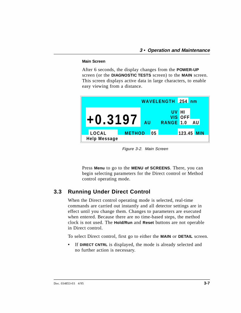
After 6 seconds, the display changes from the POWER-UPscreen (or the DIAGNOSTIC TESTS screen) to the MAIN screen.This screen displays active data in large characters, to enableeasy viewing from a distance.
Press Menu to go to the MENU of SCREENS . There, you canbegin selecting parameters for the Direct control or Methodcontrol operating mode.
3.3 Running Under Direct Control
When the Direct control operating mode is selected, real-timecommands are carried out instantly and all detector settings are ineffect until you change them. Changes to parameters are executedwhen entered. Because there are no time-based steps, the methodclock is not used. The Hold/Run and Reset buttons are not operablein Direct control.
To select Direct control, first go to either the MAIN or DETAIL screen.
• If DIRECT CNTRL is displayed, the mode is already selected andno further action is necessary.
Help Message
WAVELENGTH 254 nm
UV
RANGE
HI
1.0 AU
123.45 MINLOCAL METHOD 05
AU+0.3197 VIS OFF
Figure 3-2. Main Screen
3 • Operation and Maintenance
Doc. 034853-03 4/95 3-7
• If METHOD is displayed, move the cursor to METHOD and press theSelect ∆ or Select ∇ button to toggle between METHOD andDIRECT CNTRL in the display. Press Enter to activate the selection.
3.4 Running Under Method ControlWhen the Method control operating mode is selected, a series ofprogrammed timed events, known as a method, controls the AD20.Methods are retained in memory even when the detector power isturned off.
There are two ways to select Method control:
• Go to the MAIN or DETAIL screen. If METHOD is displayed, themode is already selected and no further action is necessary. IfDIRECT CNTRL is displayed, move the cursor to DIRECT CNTRL andpress the Select ∆ or Select ∇ button to toggle between DIRECT
CNTRL and METHOD in the display. Type in a method number andpress Enter to activate the selection.
• Go to the METHOD screen. Move the cursor to the RUN field, entera method number, and press Enter .
If the clock on the MAIN or DETAIL screen is INITwhen you pressEnter , the AD20 uses the method INITial condition parameters tocontrol the module. If the method clock is greater than zero whenyou press Enter , the AD20 uses the method parameters in effect atthat time.
Pressing Run starts the method clock. From the INITial conditions,the time 0.00 step is executed as soon as Run is pressed. Theremaining steps are executed according to their programmed times.
AD20 Absorbance Detector
3-8 Doc. 034853-03 4/95

3.4.1 Creating a New Method
Methods are created from the METHOD screen. A method canbe created at any time, even while it (or another method) isrunning. Follow the steps below to create a new method. Ifnecessary, refer to Section 2.1.1 for a review of the functionof the front panel buttons.
1. Go to the METHOD screen. Enter an unused methodnumber from 0 through 99 in the EDIT field and pressEnter . This displays a blank method on the screen.
The first step of every method is an initial conditions stepwith INIT in the TIME field. The second step is always timestep with 0.00 in the TIME field. You cannot delete thesesteps, although you may change their parameters.
2. Enter the parameters for the initial conditions and time0.00 steps.
NOTEThe TIME field is the only field in each method stepthat must have an entered value. Leaving any otherfield blank indicates that there is “no change” fromthe value selected for that parameter in the precedingstep.
Help Message
1.0
TTL RLY
01
1
METHOD EDIT SAVE TO RUN 253333
TIME RANGE AU 2 1 20 0 0
1
OFFSET MRKINIT0.000.02
v
* *
nm250
4.00
Figure 3-3. Method Screen
3 • Operation and Maintenance
Doc. 034853-03 4/95 3-9
3. To create a new method step, move the cursor to a blankTIME field, enter the time (in minutes) at which you wishan action to be performed, and press Enter . Enter thevalues for each step parameter, or leave a field blank tohave the previously selected value remain in effect.
4. Repeat Step 3 to add additional steps. Up to 30 steps (32steps, if PeakNet Software is used) can be added after thetime 0.00 step. If the method contains more steps than canbe displayed on the screen at one time, you can view theadditional steps by moving the cursor to the top or bottomscreen entry and then stepping one more line, as describedhere:
• When there is a small v next to the time entry at thebottom of the screen, move the cursor down to view theadditional steps.
• When there is a caret (^) next to the top time entry, movethe cursor up to view the additional steps.
5. To save the new method, move the cursor to the SAVE TOfield, enter the number that appears in the EDIT field, andpress Enter .
3.4.2 Editing an Existing Method
You can modify an existing method by changing, adding, ordeleting steps and/or parameters. If you edit a method whileit is running, the changes are stored in memory when youSAVE TO the method number. Changes take effect as soon asthey are saved.
To edit an existing method, go to the METHOD screen, enterthe method number in the EDIT field, and press Enter . Editthe method as described in one of the following sections.Always save your changes before exiting the METHOD screen;if you do not, the changes will be lost.
AD20 Absorbance Detector
3-10 Doc. 034853-03 4/95
NOTEOnce you save editing changes to a method, there is noway to recall the original method. If you want to makechanges to a method while retaining the originalmethod in its unmodified form, save the new method,or a copy of the original method, under a differentmethod number.
Changing Method Parameters
Move the cursor to the field(s) you want to edit and enter anew value, using the front panel buttons. Press Enter aftereach editing change.
Adding a Method Step
There are two ways to add a step to an existing method:
• Move the cursor on the METHOD screen to any TIME field.Enter the time and parameters for the new step, and thenpress Enter . If the new step is not at the correctchronological point in the method, it will be moved to thecorrect location.
• Move the cursor on the METHOD screen to the lineimmediately preceding the intended location of the newstep. Press Insert to insert a new, blank line below thecursor location. Enter the time and parameters for the newstep, and then press Enter .
Deleting a Method Step
Move the cursor on the METHOD screen to the time of thestep to be deleted and press Delete twice.
Deleting an Entire Method
Move the cursor on the METHOD screen to the EDIT field andpress Delete twice.
3 • Operation and Maintenance
Doc. 034853-03 4/95 3-11
Saving a Modified Method
To replace the original method with the modified version,enter the number of the original method in the SAVE TO fieldand press Enter .
To retain the original method and save the modified versionelsewhere in memory, enter an unused method number in theSAVE TO field and press Enter .
3.4.3 Running a Method
1. Go to the MAIN or DETAIL screen. If necessary, toggle fromDIRECT CNTRL to METHOD and from REMOTE to LOCAL .
2. In the METHOD field, enter the desired method number andpress Enter . (You can also select the method number fromthe METHOD screen. To do so, move the cursor to the RUNfield, enter a method number, and press Enter .)
3. If the method clock is already running when you enter themethod number, the method will start immediately. If theclock is in Hold, press Hold/Run to start the method.
4. The elapsed time on the method clock when the methodbegins determines where (i.e., at what step and parameters)the method begins running:
• If the method clock is at INIT or time zero, the methodbegins running using the INIT condition parameters.
• If the method clock is greater than zero, the methodbegins running using the parameters specified in thestep for that elapsed time. Press Reset to start themethod at the INIT conditions.
AD20 Absorbance Detector
3-12 Doc. 034853-03 4/95
3.4.4 Changing the Running Method
To change from the method currently running and beginrunning a different method, enter the new method number inthe RUN field on the METHOD screen and press Enter .
The new method begins running using the parametersspecified in the step for the current elapsed time. Press Resetto start the method at the INIT conditions.
3.5 Controlling Another Instrument
The AD20 can control another instrument through the TTLand Relay ports. The TTLs and Relays are programmablewithin methods, or may be controlled immediately throughDirect control. Similarly, another instrument, such as theGP40 Gradient Pump, can control the AD20 by a method inthe pump through the TTL input ports in the AD20.
The chromatography system is typically set up so that onemodule (the pump or autosampler, for instance) contains theMethod control and drives other modules (such as thedetectors).
3.6 DX LAN Remote Operation
When a PeakNet Workstation is connected to the AD20 via theoptional DX LAN interface, you can monitor the detector statusremotely and control all detector functions from the computer. Formore information, refer to the PeakNet Software User’s Guide.
3 • Operation and Maintenance
Doc. 034853-03 4/95 3-13
3.7 Routine Maintenance
• Periodically check liquid line connections to the cell for leaksand wipe up any spills.
• The PEEK tubing and fitting components may eventually loosenand leak, or pinch off and plug. Periodically check all PEEKtubing for leaks (leaks are sometimes indicated by increasingpressure). Replace tubing and fittings as required (Section 5.1).
• Periodically check the drain tube connected to the leak tray inthe optical chassis to make sure the tube is routed below the leaktray and that it is not clogged.
• Replace the lamps when needed. The life expectancy of eachlamp depends on the power setting at which it is routinelyoperated. See Sections 5.5 and 5.6 for replacement instructionsfor the deuterium and tungsten lamps, respectively.
• The CPU card contains a single-use lithium battery with a lifeexpectancy of 5 years. Dispose of the battery in accordance withlocal regulations regarding the disposal of lithium. The batterydoes not contain mercury or heavy metals.
• Repassivate stainless steel systems periodically, especially after amajor disassembly or if the system has lost passivation.Operation with extremes of pH will shorten the life of thepassivation finish. For instructions, see Passivation of StainlessSteel Systems and Components (Document No. 031152).
• Before shutting down the detector for more than 24 hours, flushthe system with water to rinse corrosive acids, salts, or basesfrom the stainless steel flow paths.
AD20 Absorbance Detector
3-14 Doc. 034853-03 4/95
4 • Troubleshooting
4.1 No Detector Response . . . . . . . . . . . . . . . 4-3
4.2 Noisy Baseline . . . . . . . . . . . . . . . . . . . 4-4
4.3 Drifting Baseline . . . . . . . . . . . . . . . . . . 4-5
4.4 High Background Absorbance . . . . . . . . . . . 4-6
4.5 Peaks Too Large or Small . . . . . . . . . . . . . 4-7
4.6 Lamp Does Not Light . . . . . . . . . . . . . . . . 4-7
4.7 Detector Does Not Autozero . . . . . . . . . . . . 4-7
4.8 Cannot Calibrate Wavelength . . . . . . . . . . . 4-8
4.9 Faulty DX LAN Communication . . . . . . . . . 4-8
4.10 Diagnostics . . . . . . . . . . . . . . . . . . . . . 4-9
Doc. 034853-03 4/95 4-1

AD20 Absorbance Detector
4-2 Doc. 034853-03 4/95
4 • Troubleshooting
This chapter is a guide to troubleshooting routine problems that mayoccur while operating the AD20 Absorbance Detector. To use thischapter, turn to the section that best describes the operating problem.The possible causes of the problem are listed there in order ofprobability, along with the recommended courses of action. Foradditional help, refer to the description of the AD20 diagnosticscreens in Appendix C.
If unable to eliminate a problem on your own, notify your Dionexoffice.
4.1 No Detector Response
• Analog output range set too high; although the displayindicates a response, no recorder response is observed
Select a more sensitive analog output range.
• No full-scale output selected
Select 0.01, 0.10, or 1 volt full-scale.
• Pump is not pumping
Check the pressure reading on the pump to make sure the pumpis on.
• Detector offset out of range
Press Offset on the front panel.
• Lamp not turned on
Turn on the lamp.
Doc. 034853-03 4/95 4-3
4.2 Noisy Baseline
• Insufficient time for system equilibration after turning on thelamp(s), or after a change in mobile phase strength orcomposition
For most applications, allow at least 15 to 20 minutes for thelamp(s) to warm up. At high sensitivities, a longer warm-upperiod may be required. After changing mobile phases, allow 20to 30 column volumes.
Check to see whether the noise is synchronized with the pumpstroke; if it is, the piston seal or check valves may need cleaning.Refer to the pump manual for instructions.
• Leaking fittings
Locate the source of the leak. Tighten or, if necessary, replace allliquid line connections. If the connections are made with Dionexferrule fittings, refer to Installation of Dionex Ferrule Fittings fortightening requirements.
• Mobile phase or post-column reagent contains light-absorbing impurities
Prepare all mobile phases and reagents with spectro-gradesolvents, reagent-grade chemicals, and ASTM Type I (or better)filtered, deionized water.
• Lamp is dimming
The light output of the lamp decreases over time. Although thelamp may still be functional, the lower light output may increasenoise above an acceptable level, especially once the lamp hasbeen in service for more than 1000 hours. If this occurs, replacethe lamp. Sections 5.5 and 5.6 contain instructions on replacingthe deuterium lamp and tungsten lamp, respectively.
AD20 Absorbance Detector
4-4 Doc. 034853-03 4/95
• Vibration
Make sure both AD20 front doors are closed during operation.
Make sure no liquid lines are in contact with the photodiodecable.
• Air bubbles in the flow cell
Remove the trapped air (Section 5.3).
Degas all solvents before use.
Install a backpressure regulator after the flow cell.
• Contaminants in the flow cell
Clean the cell (Section 5.2).
• Strongly-retained components from a previous analysis areslowly eluting from the column
To elute strongly-retained species, use a stronger mobile phase.Reequilibrate with the standard mobile phases before resumingnormal operation.
Clean the columns as instructed in the column manual. If theproblem persists, refer to the troubleshooting section of thecolumn manual for guidance.
4.3 Drifting Baseline• Leaking flow cell
Replace the flow cell.
4 • Troubleshooting
Doc. 034853-03 4/95 4-5
4.4 High Background Absorbance
• Mobile phase absorbs strongly at the wavelength in use
Change the position of the cell in the flow system.
Select an alternate detection wavelength.
Change the mobile phase composition.
• Impurities in the mobile phase or post-column reagent
Prepare all mobile phases and reagents with spectro-gradesolvents, reagent-grade chemicals, and ASTM Type I (or better)filtered, deionized water.
• Incorrect post-column reagent flow rate and/or concentration
Verify that the reagent flow rate is correct. If necessary, remakethe reagent and verify the concentration.
• Air bubbles trapped in the cell
Remove the trapped air (Section 5.3).
Check that all fittings are tight.
Degas all solvents before use.
Install a backpressure regulator after the flow cell.
• Film deposited on the cell windows
Clean the cell (Section 5.2).
AD20 Absorbance Detector
4-6 Doc. 034853-03 4/95
4.5 Peaks Too Large or Small
• Several diverse minor problems
Check the recorder and integrator input voltage. Verify that theselected full-scale deflection is correct for your recorder. Selectthe full-scale voltage from the ANALOG OUT SETUP screen.
Select a less-sensitive output range.
Change the sample volume or concentration.
Check that the post-column reagent, if used, has not degraded.Verify that the reagent flow rate is correct.
4.6 Lamp Does Not Light
• Lamp is aged or burned out
Replace the lamp. See Section 5.5 or 5.6 for instructions onreplacing the deuterium lamp and tungsten lamp, respectively.
4.7 Detector Does Not Autozero• The lamp has aged, or one or both lamps has burned out
Replace the lamp. See Section 5.5 or 5.6 for instructions onreplacing the deuterium lamp and tungsten lamp, respectively.
• Condensation on the cell
Clean the cell window or lenses using filtered, dry air.
• Loose electrical connection
Make sure the photodiode cables are latched to the pre-amp, andthen check that the pre-amp ribbon cable is fully seated in itsconnector on the SP1 card. Rezero the detector.
4 • Troubleshooting
Doc. 034853-03 4/95 4-7
4.8 Cannot Calibrate Wavelength
• Improperly connected cable(s)
Open the door to the electrical chassis and make sure thefollowing are connected and fully seated: the lamp cable(s),pre-amp cable, index cable, and grating drive cable. Refer toFigure 2-3, or to the label inside the upper front door, for thecomponent locations.
• Calibration is not enabled
Enable lamp calibration (Section C.2.7).
4.9 Faulty DX LAN Communication• DX LAN interface incorrectly installed
Make sure a BNC tee connector (P/N 921914) is connected tothe DX LAN connector on the AD20 rear panel. Connect the DXLAN cable (P/N 960404) to one side of the BNC tee connector.The DX LAN cable must be RG58U or RG58AU. Do not userecorder cables; they have the wrong impedance and willinterfere with signals on the DX LAN.
Make sure that the tee connectors at both ends of the network arecapped with the terminator plugs (P/N 921034) that are shippedwith PeakNet Software. See Section B.3.7 for more information.
AD20 Absorbance Detector
4-8 Doc. 034853-03 4/95
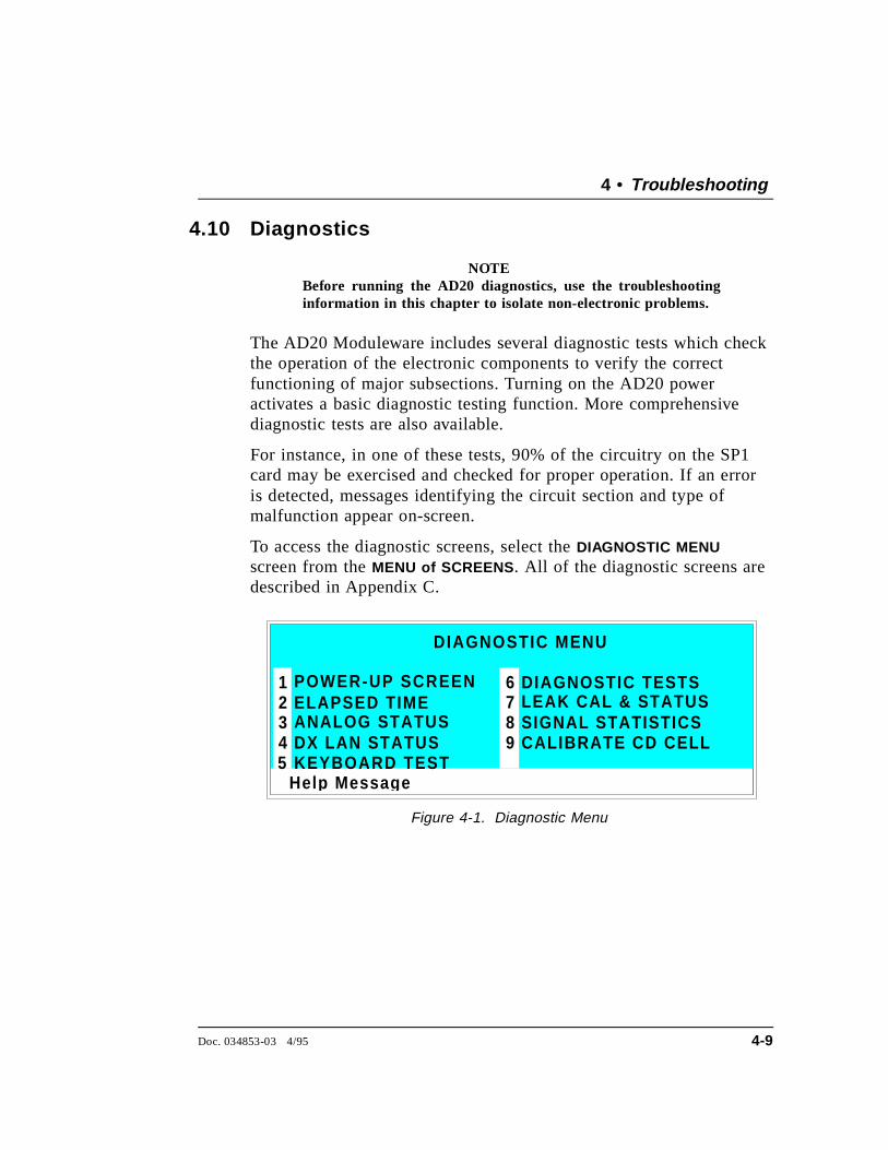
4.10 Diagnostics
NOTEBefore running the AD20 diagnostics, use the troubleshootinginformation in this chapter to isolate non-electronic problems.
The AD20 Moduleware includes several diagnostic tests which checkthe operation of the electronic components to verify the correctfunctioning of major subsections. Turning on the AD20 poweractivates a basic diagnostic testing function. More comprehensivediagnostic tests are also available.
For instance, in one of these tests, 90% of the circuitry on the SP1card may be exercised and checked for proper operation. If an erroris detected, messages identifying the circuit section and type ofmalfunction appear on-screen.
To access the diagnostic screens, select the DIAGNOSTIC MENUscreen from the MENU of SCREENS . All of the diagnostic screens aredescribed in Appendix C.
Hel p Messa g e
POWER-UP SCREENELAPSED TIMEANALOG STATUS DX LAN STATUS
DIAGNOSTIC TESTSLEAK CAL & STATUSSIGNAL STATISTICSCALIBRATE CD CELL
12345
678
DIAGNOSTIC MENU
KEYBOARD TEST9
Figure 4-1. Diagnostic Menu
4 • Troubleshooting
Doc. 034853-03 4/95 4-9

AD20 Absorbance Detector
4-10 Doc. 034853-03 4/95

5 • Service
5.1 Liquid Leaks . . . . . . . . . . . . . . . . . . . . . 5-3
5.2 Cleaning the Cell . . . . . . . . . . . . . . . . . . 5-3
5.3 Removing Trapped Air from the Cell . . . . . . . 5-4
5.4 Replacing the Main Power Fuses . . . . . . . . . 5-4
5.5 Replacing the Deuterium Lamp . . . . . . . . . . 5-6
5.6 Replacing the Tungsten Lamp . . . . . . . . . . . 5-7
Doc. 034853-03 4/95 5-1

AD20 Absorbance Detector
5-2 Doc. 034853-03 4/95
5 • Service
This chapter describes routine service procedures for the AD20Absorbance Detector. Before replacing any parts, refer to thetroubleshooting information in Chapter 4 to isolate the cause of theproblem. When ordering replacement parts, please include the modelnumber and serial number of the detector.
Substituting non-Dionex parts may impair detector performance,thereby voiding the product warranty. Refer to the warrantystatement in the Dionex Terms and Conditions for more information.
NOTEThe AD20 electronic components are not customer-serviceable.Any repairs involving the electronics must be performed byDionex.
5.1 Liquid Leaks
The PEEK version of the AD20 is plumbed with 1.60-mm (1/16-in)PEEK tubing and Dionex ferrule fittings (P/N 043276) and 10-32fitting bolts (P/N 043275). For tightening requirements, refer toInstallation of Dionex Ferrule Fittings.
5.2 Cleaning the CellFilm deposits on the cell windows cause excessive baseline noiseor high absorbance offset.
1. Disconnect the liquid lines from the cell in and out connections.
2. Connect a luer adapter to the cell in connection.
3. Using a syringe, flush the cell with a succession of deionizedwater, acetone, and 3 M HNO3. Finally, flush it again withdeionized water.
4. Reconnect the cell inlet and outlet lines.
Doc. 034853-03 4/95 5-3
5.3 Removing Trapped Air from the Cell
Air trapped in the cell may cause regular pulsations of thebaseline. In addition, trapped air bubbles may cause randomnoise and low readings. The trapped air may result from air thatwas introduced in the columns during installation, or fromeluent outgassing.
To remove persistent bubbles and avoid outgassing, install an inertbackpressure regulator (PEEK regulator, P/N 046480; stainless steelregulator, P/N 039760). The cell backpressure should not exceed1.38 mPa (200 psi).
An alternative is to install a backpressure line. This increases thecell backpressure, thereby shrinking bubbles and allowing them topass more easily through the cell. Install a length of 0.25-mm(0.010-in) ID tubing (P/N 042690), with fittings on both ends, afterthe cell outlet. The backpressure line should be 1 meter long at aflow rate of 1.0 mL/min, 2 meters at 0.5 mL/min, etc. Use a union(P/N 042627) to connect the backpressure line to the waste line.
Do not pump eluent through the column at a flow ratemuch faster than normal; overpressurization will damagethe column.
5.4 Replacing the Main Power Fuses1. Turn off the AD20 main power switch. Disconnect the main
power cord from the AD20 rear panel.
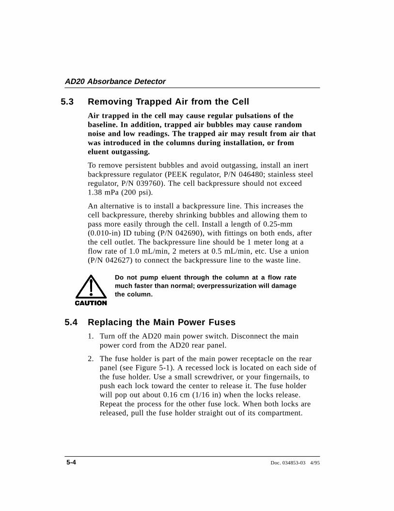
2. The fuse holder is part of the main power receptacle on the rearpanel (see Figure 5-1). A recessed lock is located on each side ofthe fuse holder. Use a small screwdriver, or your fingernails, topush each lock toward the center to release it. The fuse holderwill pop out about 0.16 cm (1/16 in) when the locks release.Repeat the process for the other fuse lock. When both locks arereleased, pull the fuse holder straight out of its compartment.
AD20 Absorbance Detector
5-4 Doc. 034853-03 4/95
3. The holder contains two fuses. Replace these with new 3.15 ampfast-blow IEC127 fuses (P/N 954745). Dionex recommendsreplacing both fuses, even though only one may be open. Theother fuse has been stressed and could fail even under normaloperation.
4. Reinsert the fuse holder into its compartment. The fuse holder iskeyed to fit only in its proper orientation. Apply enough pressureevenly against the holder to engage the two locks. When both thelocks are engaged, the holder is flush against the panel.
5. Reconnect the main power cord and turn on the power.
Figure 5-1. Main Power Receptacle
5 • Service
Doc. 034853-03 4/95 5-5
5.5 Replacing the Deuterium Lamp
1. Turn off the deuterium lamp from the AD20 front panel or fromthe PeakNet Run program. You may leave the detector mainpower on.
The lamp housing may be hot to the touch, especiallywhen the lamp has been operating at the high powersetting. Allow 5 minutes for the lamp housing to coolbefore continuing.
2. Open the door to the AD20 electronics chassis. Disconnect the6-pin UV lamp connector from the PIO card (Figure 2-3).
3. Open the door to the AD20 optical chassis. Loosen the drawerlock (see Figure B-2) and pull open the drawer to the first stop.DO NOT PULL THE DRAWER OUT FURTHER THANHALFWAY.
4. Loosen the thumbscrew in the deuterium lamp clamp and pullthe clamp away from the lamp mounting tube.
5. Hold the lamp by the top, rock it gently back and forth to loosenit from its socket, and pull the lamp straight up and away fromthe optical bench. As you do so, note the yellow arrow on thelamp. When the lamp is correctly installed, this arrow is alignedwith a locating pin in the lamp socket.
6. While holding the clamp open, align the yellow arrow on thenew deuterium lamp (P/N 045230) with the locating pin in thelamp socket and then gently push the lamp into the socket.
7. When the lamp is fully seated, fingertighten the thumbscrew inthe lamp clamp.
8. Reconnect the UV lamp connector to the PIO card. Push theoptical chassis drawer back into the detector. Make sure the lampcable is routed through the slot provided for cables and that it isnot pinched by the drawer.
9. Close both of the doors on the front of the AD20.
AD20 Absorbance Detector
5-6 Doc. 034853-03 4/95
NOTEIf you turned off the AD20 main power before replacing the lamp,skip Steps 10 and 11. The lamp will be recalibrated when youturn on the detector power again.
10. Select Local control. Set the deuterium lamp to High. Afterturning on the lamp, wait 1 minute for it to warm up.
11. Go to the DIAGNOSTIC TESTS screen and select UV CAL toinitiate recalibration of the deuterium lamp. When calibration iscomplete, the detector is ready for normal operation.
5.6 Replacing the Tungsten Lamp
1. Turn off the tungsten lamp from the AD20 front panel or fromthe PeakNet Run program. You may leave the detector mainpower on.
The lamp housing may be hot to the touch, especiallywhen the lamp has been operating at the high powersetting. Allow 5 minutes for the lamp housing to coolbefore continuing.
2. Open the door to the AD20 electronics chassis. Disconnect theVis lamp connector from the PIO card (Figure 2-3).
3. Open the door to the AD20 optical chassis. Loosen the drawerlock (see Figure B-2) and pull open the drawer to the first stop.DO NOT PULL THE DRAWER OUT FURTHER THANHALFWAY.
4. Loosen the tungsten lamp thumbscrews and pull the mountingassembly away from the rear of the optical bench.
5 • Service
Doc. 034853-03 4/95 5-7
5. Using a Phillips screwdriver, remove the screw securing thetungsten lamp assembly to the socket and remove the assembly.
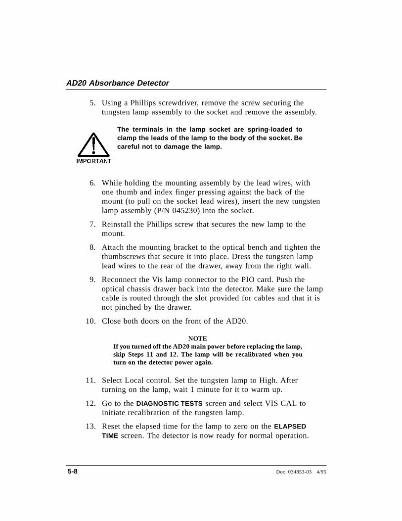
The terminals in the lamp socket are spring-loaded toclamp the leads of the lamp to the body of the socket. Becareful not to damage the lamp.
6. While holding the mounting assembly by the lead wires, withone thumb and index finger pressing against the back of themount (to pull on the socket lead wires), insert the new tungstenlamp assembly (P/N 045230) into the socket.
7. Reinstall the Phillips screw that secures the new lamp to themount.
8. Attach the mounting bracket to the optical bench and tighten thethumbscrews that secure it into place. Dress the tungsten lamplead wires to the rear of the drawer, away from the right wall.
9. Reconnect the Vis lamp connector to the PIO card. Push theoptical chassis drawer back into the detector. Make sure the lampcable is routed through the slot provided for cables and that it isnot pinched by the drawer.
10. Close both doors on the front of the AD20.
NOTEIf you turned off the AD20 main power before replacing the lamp,skip Steps 11 and 12. The lamp will be recalibrated when youturn on the detector power again.
11. Select Local control. Set the tungsten lamp to High. Afterturning on the lamp, wait 1 minute for it to warm up.
12. Go to the DIAGNOSTIC TESTS screen and select VIS CAL toinitiate recalibration of the tungsten lamp.
13. Reset the elapsed time for the lamp to zero on the ELAPSEDTIME screen. The detector is now ready for normal operation.
AD20 Absorbance Detector
5-8 Doc. 034853-03 4/95
A • Specifications
A.1 Electrical . . . . . . . . . . . . . . . . . . . . . . . A-3
A.2 Environmental . . . . . . . . . . . . . . . . . . . . A-3
A.3 Physical . . . . . . . . . . . . . . . . . . . . . . . A-3
A.4 Display and Keypad . . . . . . . . . . . . . . . . . A-3
A.5 Detector . . . . . . . . . . . . . . . . . . . . . . . A-4
A.6 Flow Cell . . . . . . . . . . . . . . . . . . . . . . A-5
A.7 Heat Exchanger . . . . . . . . . . . . . . . . . . . A-5
Doc. 034853-03 4/95 A-1

AD20 Absorbance Detector
A-2 Doc. 034853-03 4/95
A • Specifications
A.1 Electrical
Main Power 90 to 265 Vac, 47/63 Hz; 150 W Max, 100 W typical.The power supply is auto-sensing and requires no voltageadjustment.
Fuse Two 3.15 amp fast-blow IEC127 fuses (P/N 954745)
Analog Output User-selectable full-scale output of 10, 100, or 1000 mV
A.2 Environmental
OperatingTemperature
10 ºC to 40 ºC (50 ºF to 104 ºF)
OperatingHumidity
5 to 95% relative humidity (non-condensing)
A.3 Physical
Dimensions 22.5 cm W x 33.5 cm H x 42.0 cm D(8.8 in W x 13.1 in H x 16.4 in D)6 cm (2.4 in) clearance required behind the detector
Weight 13.6 kg (30 lbs)
A.4 Display and Keypad
Display Liquid crystal display with adjustable backlighting
Keypad 26 buttons for entering commands and numerical values forscreen parameters
Doc. 034853-03 4/95 A-3
A.5 Detector
Optical System Dual-beam, fiber-optic beamsplitter and concave holographicdiffraction grating
Light Sources Deuterium lamp (30 W) for ultraviolet spectrum analysis;tungsten lamp (10 W) for visible spectrum analysis
WavelengthRange
190 to 800 nm variable; continuous in 1 nm steps
WavelengthAccuracy
± 1 nm
Bandwidth 8 nm
AbsorbanceRange
Discrete settings of 0.001, 0.002, 0.005, 0.01, 0.02, 0.05, 0.1,0.2, 0.5, 1.0, and 2.0 AU
AutozeroCapability
2 AU
AutozeroAccuracy
± 100 µAU
Noise < 10 µAU peak-to-peak at 254 nm, 2-second rise time,flowing deionized water
Drift < 100 µAU/hour (after warm-up)< 100 µAU/ºC (after warm-up)
Filter RiseTime
Discrete settings of 0.05, 0.1, 0.2, 0.5, 1.0, 2.0, 5.0, or 10.0seconds
Analog OutputRange
Discrete settings of 0.001, 0.002, 0.005, 0.01, 0.02, 0.05, 0.1,0.2, 0.5, 1.0, and 2.0 AUFS
LocalOperation
Front panel controls and display status of all functions
RemoteOperation
Four of the seven AD20 functions can be controlled via TTLor Relay contacts
AD20 Absorbance Detector
A-4 Doc. 034853-03 4/95
DX LANOperation(Optional)
All functions controlled by PeakNet Software on a PC, whenconnected to the AD20 via the Dionex DX LAN interface
A.6 Flow Cell
Cell Body PEEK
Volume andOptical Path
Length
Standard bore cell, used with 4 mm (0.016 in) columns: 9 µLvolume, 10 mm (0.002 in) optical path length
Narrow bore cell, used with 4 mm (0.016 in) and 2 mm(0.008 in) columns: 7.5 µL volume, 6 mm (0.002 in) opticalpath length
Microbore cell, used with 2 mm (0.008 in) columns: 2.5 µLvolume, 3 mm (0.01 in) optical path length
MaximumOperating
Pressure
1.38 mPa (200 psi) with a heat exchanger; 3.45 mPa (500 psi)without a heat exchanger
ChemicalCompatibility
The use of a base stronger than 0.1 M is not recommended, asit will etch the silica windows.
A.7 Heat Exchanger
Coil for 2 mmColumns
Volume of 20 µL; dispersion of 2.2 µL at 1.0 mL/min
Coil for 4 mmColumns
Volume of 60 µL; dispersion of 5.3 µL at 1.0 mL/min
A • Specifications
Doc. 034853-03 4/95 A-5

AD20 Absorbance Detector
A-6 Doc. 034853-03 4/95
B • Installation
B.1 Facilities Required . . . . . . . . . . . . . . . . . B-3
B.2 System Configuration . . . . . . . . . . . . . . . . B-4
B.3 Unpacking . . . . . . . . . . . . . . . . . . . . . . B-5
B.4 Installation . . . . . . . . . . . . . . . . . . . . . . B-6
B.4.1 Power . . . . . . . . . . . . . . . . . . . . B-6
B.4.2 Flow Cell . . . . . . . . . . . . . . . . . . B-7
B.4.3 Heat Exchanger . . . . . . . . . . . . . . B-9
B.4.4 Waste Line . . . . . . . . . . . . . . . . . B-9
B.4.5 Detector Output . . . . . . . . . . . . . . B-9
B.4.6 Relay/TTL Control . . . . . . . . . . . . B-10
B.4.7 DX LAN Network (Optional) . . . . . . . B-12
Doc. 034853-03 4/95 B-1

AD20 Absorbance Detector
B-2 Doc. 034853-03 4/95
B • Installation
B.1 Facilities Required
• Make sure the AD20 installation site meets the electrical andenvironmental specifications listed in Appendix A.
• Install the AD20 on a sturdy table or workbench, at a height thatensures convenient viewing of the front panel display.
• Allow at least 6 cm (2.4 in) clearance behind the detector forpower connections and ventilation. Room air is inducted into thedetector to cool the electronics and dissipate the heat generatedby the lamps. Do not obstruct air flow to the rear of the detector.
Doc. 034853-03 4/95 B-3
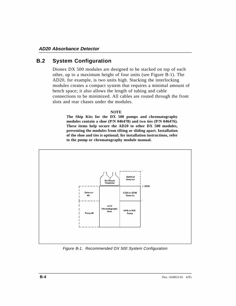
B.2 System Configuration
Dionex DX 500 modules are designed to be stacked on top of eachother, up to a maximum height of four units (see Figure B-1). TheAD20, for example, is two units high. Stacking the interlockingmodules creates a compact system that requires a minimal amount ofbench space; it also allows the length of tubing and cableconnections to be minimized. All cables are routed through the frontslots and rear chases under the modules.
NOTEThe Ship Kits for the DX 500 pumps and chromatographymodules contain a shoe (P/N 046478) and two ties (P/N 046476).These items help secure the AD20 to other DX 500 modules,preventing the modules from tilting or sliding apart. Installationof the shoe and ties is optional; for installation instructions, referto the pump or chromatography module manual.
Figure B-1. Recommended DX 500 System Configuration
AD20 Absorbance Detector
B-4 Doc. 034853-03 4/95
B.3 Unpacking
When moving or carrying the AD20, lift only from thebottom or side of the detector. Lifting with the front paneldoor will damage the door hinges.
1. Carefully remove the AD20 from its shipping container, usingthe lift strap. Be careful not to tip the detector forward.
2. Open the door to the optical chassis (the lower unit of the AD20enclosure). Loosen the drawer lock (see Figure B-2) and pullopen the drawer to the first stop.
3. Two bolts clamp the optical bench to the optical chassis drawer(see Figure B-2) to prevent shipping damage. Loosen the screwon each shipping bolt three turns. Note: If it is ever necessary toreship the detector, remember to first retighten these screws.
Figure B-2. Optical Bench Shipping Bolts
B • Installation
Doc. 034853-03 4/95 B-5
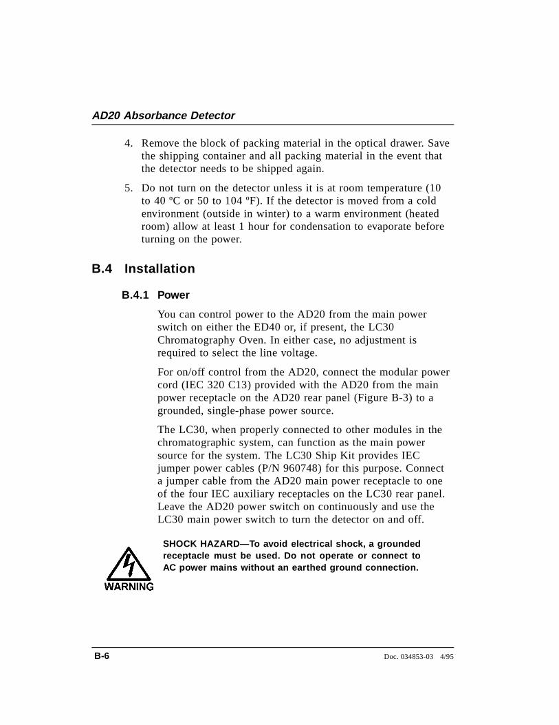
4. Remove the block of packing material in the optical drawer. Savethe shipping container and all packing material in the event thatthe detector needs to be shipped again.
5. Do not turn on the detector unless it is at room temperature (10to 40 ºC or 50 to 104 ºF). If the detector is moved from a coldenvironment (outside in winter) to a warm environment (heatedroom) allow at least 1 hour for condensation to evaporate beforeturning on the power.
B.4 Installation
B.4.1 Power
You can control power to the AD20 from the main powerswitch on either the ED40 or, if present, the LC30Chromatography Oven. In either case, no adjustment isrequired to select the line voltage.
For on/off control from the AD20, connect the modular powercord (IEC 320 C13) provided with the AD20 from the mainpower receptacle on the AD20 rear panel (Figure B-3) to agrounded, single-phase power source.
The LC30, when properly connected to other modules in thechromatographic system, can function as the main powersource for the system. The LC30 Ship Kit provides IECjumper power cables (P/N 960748) for this purpose. Connecta jumper cable from the AD20 main power receptacle to oneof the four IEC auxiliary receptacles on the LC30 rear panel.Leave the AD20 power switch on continuously and use theLC30 main power switch to turn the detector on and off.
SHOCK HAZARD—To avoid electrical shock, a groundedreceptacle must be used. Do not operate or connect toAC power mains without an earthed ground connection.
AD20 Absorbance Detector
B-6 Doc. 034853-03 4/95
Operation at AC input levels outside of the operatingvoltage specified range may damage the detector.
B.4.2 Flow Cell
1. Thread the cell onto the photodiode. Be careful not totouch the cell window. If you accidentally touch thewindow, clean it with denatured alcohol and a clean tissue.
2. The tubing used for cell connections depends on the lengthof the optical path:
• For standard bore (10 mm) and narrow bore (6 mm)cells, 0.25-mm (0.010-in) ID tubing is recommended.
• For microbore (3 mm) cells, 0.125-mm (0.005-in) IDtubing may be used.
Figure B-3. AD20 Rear Panel
B • Installation
Doc. 034853-03 4/95 B-7
3. Attach the outlet line to the top of the cell and the inletline to the bottom of the cell. For easiest access, the outlettube fitting should angle toward the beamsplitter mount,and the inlet fitting should angle toward the photodiode.Connecting the inlet tubing to the bottom will help preventair bubbles from being trapped in the cell.
4. You are now ready to mount the cell on the angled face ofthe beamsplitter. This orientation minimizes dead volume.For trace-level analyses, mount the cell on the left side ofthe beamsplitter. For other applications, you may mountthe cell on either the right or left side.
After docking the cell to the optical port, align the cellsquare with the beamsplitter, with the cell latches clear ofthe latch pins, and twist the cell slightly while pushing itonto the face of the beamsplitter. (The optical bench maymove slightly, as it is shock-mounted.)
5. If the cell outlet connection provides some restriction,thereby generating a small amount of backpressure, bubbleformation will be minimized. An inert backpressureregulator (PEEK regulator, P/N 046480; stainless steelregulator, P/N 039760) or a backpressure line consisting of100 cm of 0.25-mm (0.010-in) ID capillary tubing isrecommended for this purpose.
Do not use normal phase or chlorinated solvents withPEEK components, as these will damage the flow cell.
AD20 Absorbance Detector
B-8 Doc. 034853-03 4/95
B.4.3 Heat Exchanger
Operating at backpressures greater than 1.38 mPa(200 psi) will damage the heat exchanger. For applicationsthat require extremely low dead volume, or have very highbackpressure after the detector, you may bypass the heatexchanger.
The heat exchanger assembly is mounted immediately belowthe flow cell. Connections to the heat exchanger are made atthe manifold. Connect the cell inlet to either port of themanifold.
B.4.4 Waste Line
Connect the leak drain tube to the rear of the optical chassisdrawer, near the base. Place the free end of the tubing in anapproved waste container below the bench level.
B.4.5 Detector Output
The recorder connections are accessible in the electronicschassis.
Connect a recorder or an integrator to the 3-pin connector onthe SP1 analog output, using the twisted wire (P/N 043598)and connector (P/N 921186) provided in the AD20 Ship Kit.The connector pinout is as follows:
Pin 1 Signal + Pin 2 Signal - Pin 3 Chassis ground
(some installations may require a grounded shield)
B • Installation
Doc. 034853-03 4/95 B-9
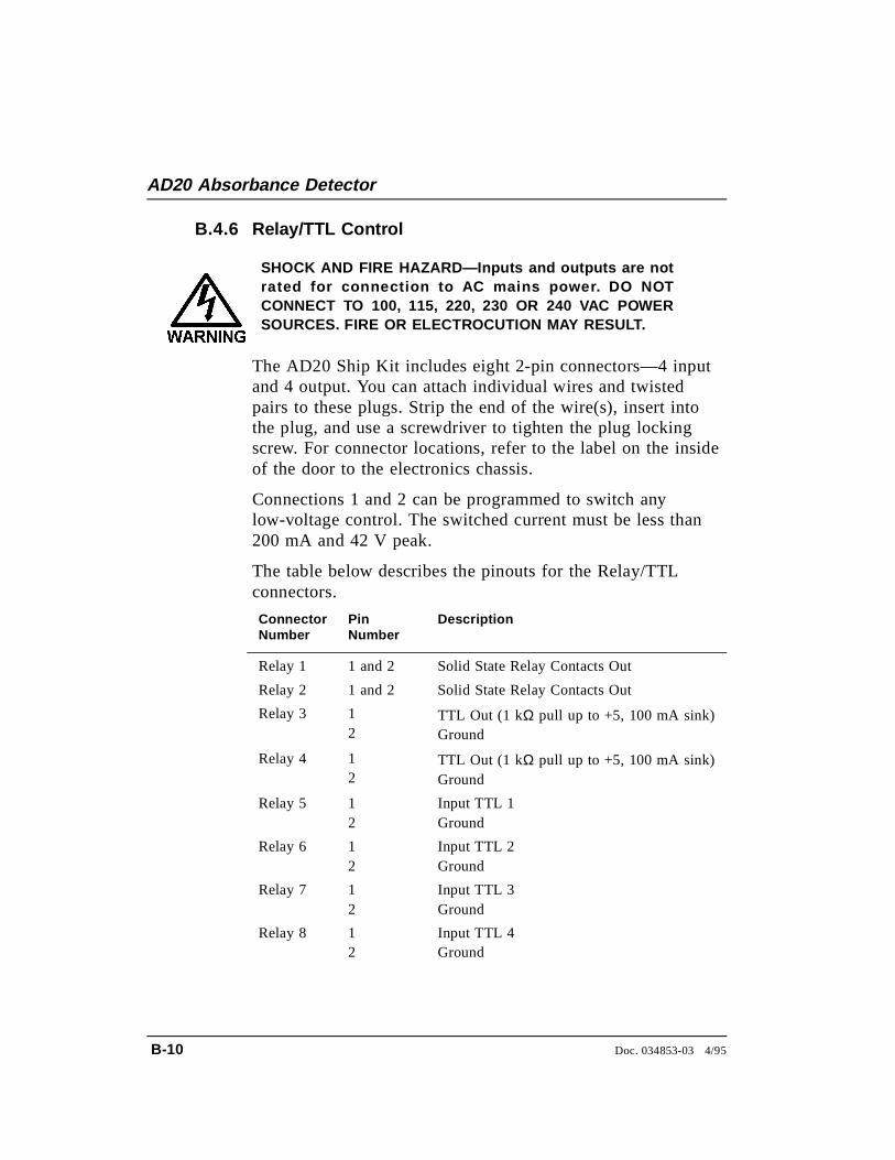
B.4.6 Relay/TTL Control
SHOCK AND FIRE HAZARD—Inputs and outputs are notrated for connection to AC mains power. DO NOTCONNECT TO 100, 115, 220, 230 OR 240 VAC POWERSOURCES. FIRE OR ELECTROCUTION MAY RESULT.
The AD20 Ship Kit includes eight 2-pin connectors—4 inputand 4 output. You can attach individual wires and twistedpairs to these plugs. Strip the end of the wire(s), insert intothe plug, and use a screwdriver to tighten the plug lockingscrew. For connector locations, refer to the label on the insideof the door to the electronics chassis.
Connections 1 and 2 can be programmed to switch anylow-voltage control. The switched current must be less than200 mA and 42 V peak.
The table below describes the pinouts for the Relay/TTLconnectors.
ConnectorNumber
PinNumber
Description
Relay 1 1 and 2 Solid State Relay Contacts Out
Relay 2 1 and 2 Solid State Relay Contacts Out
Relay 3 12
TTL Out (1 kΩ pull up to +5, 100 mA sink)Ground
Relay 4 12
TTL Out (1 kΩ pull up to +5, 100 mA sink)Ground
Relay 5 12
Input TTL 1Ground
Relay 6 12
Input TTL 2Ground
Relay 7 12
Input TTL 3Ground
Relay 8 12
Input TTL 4Ground
AD20 Absorbance Detector
B-10 Doc. 034853-03 4/95
TTL inputs 1, 2, 3, and 4 (relays 5 through 8) in thepreceding table can be used to control the following functions:
• OFFSET Recorder
• HOLD/RUN Program
• UV LAMP ON/OFF
• TUNGSTEN LAMP ON/OFF
• METHOD NUMBER INCR
• METHOD NUMBER DECR
• MARK Recorder
• Increase Recorder RANGEx10
See Section C.1.7 for setup instructions.
The relay output, TTL output, and TTL inputs use the samestyle of connector. Connection of relay loads and theirpower sources to the TTL outputs will damage the TTLoutput stage. If the relay load can source more than 200mA at 5V or higher, damage to the CPU module may result.
B • Installation
Doc. 034853-03 4/95 B-11
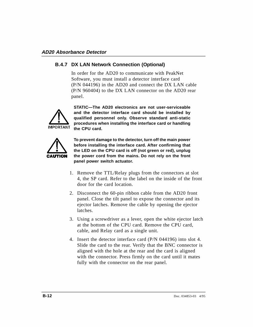
B.4.7 DX LAN Network Connection (Optional)
In order for the AD20 to communicate with PeakNetSoftware, you must install a detector interface card(P/N 044196) in the AD20 and connect the DX LAN cable(P/N 960404) to the DX LAN connector on the AD20 rearpanel.
STATIC—The AD20 electronics are not user-serviceableand the detector interface card should be installed byqualified personnel only. Observe standard anti-staticprocedures when installing the interface card or handlingthe CPU card.
To prevent damage to the detector, turn off the main powerbefore installing the interface card. After confirming thatthe LED on the CPU card is off (not green or red), unplugthe power cord from the mains. Do not rely on the frontpanel power switch actuator.
1. Remove the TTL/Relay plugs from the connectors at slot4, the SP card. Refer to the label on the inside of the frontdoor for the card location.
2. Disconnect the 60-pin ribbon cable from the AD20 frontpanel. Close the tilt panel to expose the connector and itsejector latches. Remove the cable by opening the ejectorlatches.
3. Using a screwdriver as a lever, open the white ejector latchat the bottom of the CPU card. Remove the CPU card,cable, and Relay card as a single unit.
4. Insert the detector interface card (P/N 044196) into slot 4.Slide the card to the rear. Verify that the BNC connector isaligned with the hole at the rear and the card is alignedwith the connector. Press firmly on the card until it matesfully with the connector on the rear panel.
AD20 Absorbance Detector
B-12 Doc. 034853-03 4/95
5. Reinstall the CPU/Relay card. Press firmly until the CPUcard is inserted into the connector on the rear panel.
6. Reconnect the ribbon cable to the 60-pin connector on thefront panel. The header and connector are key-polarizednear the center. The ejector latches should be partiallyopen to accept the cable connector.
7. If the detector is the last module in the network to beconnected, install a terminator plug (P/N 921034), shippedwith PeakNet Software, on the remaining port of the BNCtee connector. If this is not the last module, connect thecable from the next module to the BNC tee.
Terminator resistor plugs must be installed at each endof the DX LAN. Verify that both ends of the DX LAN haveresistor plugs installed.
8. Connect the DX LAN cable (P/N 960404) to the DX LANconnector.
NOTEIf necessary, a 15-meter (50-ft) DX LAN extensioncable (P/N 046016) is available from Dionex.
B • Installation
Doc. 034853-03 4/95 B-13

AD20 Absorbance Detector
B-14 Doc. 034853-03 4/95
C • User Interface
C.1 Operational Screens . . . . . . . . . . . . . . . . . C-3
C.1.1 Menu of Screens . . . . . . . . . . . . . . C-4
C.1.2 Main Screen . . . . . . . . . . . . . . . . C-5
C.1.3 Detail Screen . . . . . . . . . . . . . . . . C-7
C.1.4 Method . . . . . . . . . . . . . . . . . . . C-9
C.1.5 Module Setup . . . . . . . . . . . . . . . C-11
C.1.6 Analog Out Setup . . . . . . . . . . . . . C-12
C.1.7 Time Function In . . . . . . . . . . . . . C-13
C.2 Diagnostic Screens . . . . . . . . . . . . . . . . . C-14
C.2.1 Diagnostic Menu . . . . . . . . . . . . . . C-14
C.2.2 Power-Up Screen . . . . . . . . . . . . . . C-15
C.2.3 Elapsed Time . . . . . . . . . . . . . . . . C-16
C.2.4 Analog Status . . . . . . . . . . . . . . . C-17
C.2.5 DX LAN Status . . . . . . . . . . . . . . C-19
C.2.6 Keyboard Test . . . . . . . . . . . . . . . C-21
C.2.7 Diagnostic Tests . . . . . . . . . . . . . . C-22
C.2.8 Leak Sensor Calibration and Status . . . C-25
C.2.9 Signal Statistics . . . . . . . . . . . . . . C-26
C.2.10 Offset Zero Calibration . . . . . . . . . . C-27
Doc. 034853-03 4/95 C-1

AD20 Absorbance Detector
C-2 Doc. 034853-03 4/95
C • User Interface
This appendix illustrates and describes all of the screens availablefor display on the front panel of the AD20 Absorbance Detector.There are two categories of screens: operational and diagnostic (seeFigure C-1).
• Operational screens enable you to create, edit, and run methodsthat control detector operation, and to select default parametersfor the detector.
• Diagnostic screens provide access to AD20 diagnosticinformation and tests.
MENU of SCREENS
P O W E R - U PS C R E E N
E L A P S E DTIME
DX LANSTATUS
K E Y B O A R DTEST
DETAILS C R E E N
M E T H O DEXTENSION
TIMEFUNCTION IN
MAINS C R E E N
DIAGNOSTICM E N U
1 2 3 5 6 7 8
1 2 3 5 6 7 8
Operational Screens
Diagnostic Screens
M O D U L ESETUP
ANALOG OUT SETUP
ANALOGSTATUS
4
DIAGNOSTIC TESTS
SIGNALSTATISTICS
CALIBRATE CD CELL
9
LEAK CAL& STATUS
M E T H O D
Figure C-1. AD20 Menu Structure
Doc. 034853-03 4/95 C-3
C.1 Operational Screens
C.1.1 Menu of Screens
The MENU of SCREENS provides top-level access to the menustructure.
There are two ways to select a screen from this menu:
• Use the cursor directional buttons to move the cursor tothe field containing the screen number and press Enter .
• Press the number button on the front panel keypad thatcorresponds to the screen.
To display a brief description of each menu, press the Helpbutton.
Help Message
MAIN SCREENDETAIL SCREENMETHOD- - -
MODULE SETUPANALOG OUT SETUPTIME FUNCTION INDIAGNOSTIC MENU
1234
5678
MENU of SCREENS
Figure C-2. Menu of Screens
AD20 Absorbance Detector
C-4 Doc. 034853-03 4/95
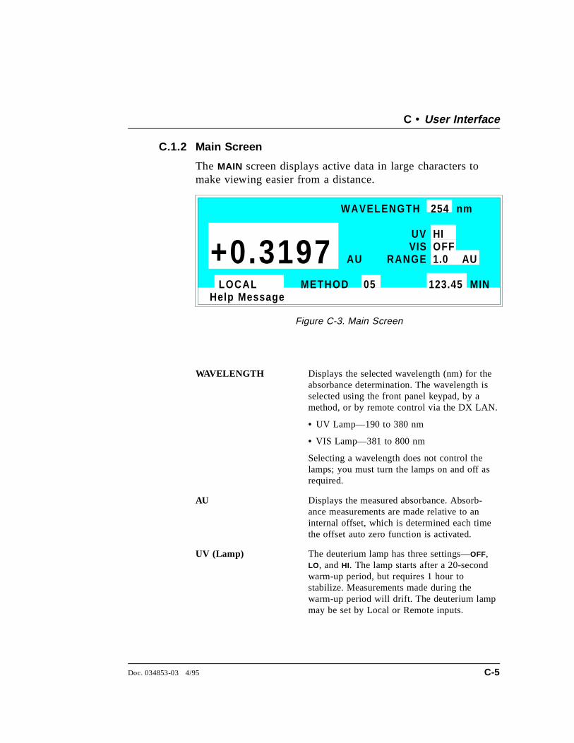
C.1.2 Main Screen
The MAIN screen displays active data in large characters tomake viewing easier from a distance.
WAVELENGTH Displays the selected wavelength (nm) for theabsorbance determination. The wavelength isselected using the front panel keypad, by amethod, or by remote control via the DX LAN.
• UV Lamp—190 to 380 nm
• VIS Lamp—381 to 800 nm
Selecting a wavelength does not control thelamps; you must turn the lamps on and off asrequired.
AU Displays the measured absorbance. Absorb-ance measurements are made relative to aninternal offset, which is determined each timethe offset auto zero function is activated.
UV (Lamp) The deuterium lamp has three settings—OFF,LO, and HI. The lamp starts after a 20-secondwarm-up period, but requires 1 hour tostabilize. Measurements made during thewarm-up period will drift. The deuterium lampmay be set by Local or Remote inputs.
Help Message
WAVELENGTH 254 nm
UV
RANGE
HI
1.0 AU
123.45 MINLOCAL METHOD 05
AU+0.3197 VIS OFF
Figure C-3. Main Screen
C • User Interface
Doc. 034853-03 4/95 C-5
VIS (Lamp) The tungsten lamp has three settings—OFF, LO,and HI. The tungsten lamp may be set by Localor Remote inputs.
RANGE There are eleven discrete settings for theanalog output (recorder) range—0.001, 0.002,0.005, 0.01, 0.02, 0.05, 0.1, 0.2, 0.5, 1.0, and2.0 AUFS. See the description of the ANALOG
OUT SETUP screen for additional analog(recorder) settings.
Control Mode Sets the detector to Local or Remote control.
MIN Shows the method clock elapsed time, initialconditions, or is blank. This value can beedited. When you enter a new elapsed time,the method settings corresponding to the newtime take effect.
AD20 Absorbance Detector
C-6 Doc. 034853-03 4/95
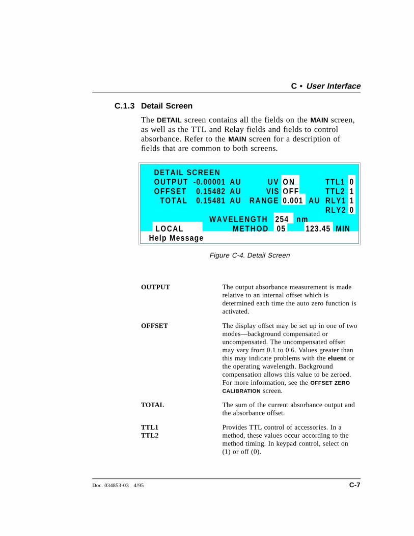
C.1.3 Detail Screen
The DETAIL screen contains all the fields on the MAIN screen,as well as the TTL and Relay fields and fields to controlabsorbance. Refer to the MAIN screen for a description offields that are common to both screens.
OUTPUT The output absorbance measurement is maderelative to an internal offset which isdetermined each time the auto zero function isactivated.
OFFSET The display offset may be set up in one of twomodes—background compensated oruncompensated. The uncompensated offsetmay vary from 0.1 to 0.6. Values greater thanthis may indicate problems with the eluent orthe operating wavelength. Backgroundcompensation allows this value to be zeroed.For more information, see the OFFSET ZERO
CALIBRATION screen.
TOTAL The sum of the current absorbance output andthe absorbance offset.
TTL1TTL2
Provides TTL control of accessories. In amethod, these values occur according to themethod timing. In keypad control, select on(1) or off (0).
Help Message
TOTAL 0.15481 RANGE
123.45 MINLOCAL M E T H O D 05
DETAIL SCREENOUTPUTOFFSET 0.15482
-0.00001 AUAUAU
TTL1TTL2RLY1RLY2
0
0
11
VIS OFF
WAVELENGTH 254 nm
UV O N
AU0.001
Figure C-4. Detail Screen
C • User Interface
Doc. 034853-03 4/95 C-7
RLY1RLY2
Provides relay contact closure control ofaccessories. In a method, these values occuraccording to the method timing. In keypadcontrol, select on (1) or off (0).
METHOD Selects the method number (0 through 99) torun.
AD20 Absorbance Detector
C-8 Doc. 034853-03 4/95
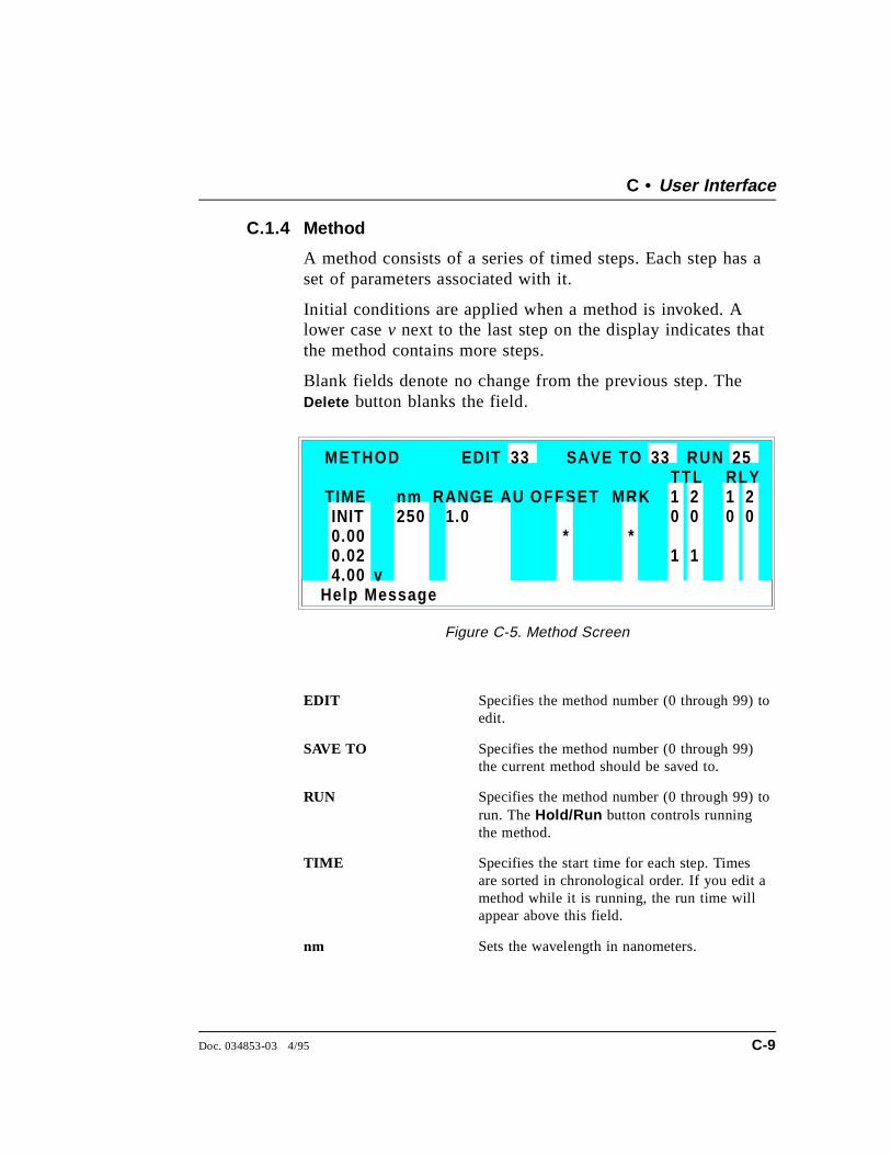
C.1.4 Method
A method consists of a series of timed steps. Each step has aset of parameters associated with it.
Initial conditions are applied when a method is invoked. Alower case v next to the last step on the display indicates thatthe method contains more steps.
Blank fields denote no change from the previous step. TheDelete button blanks the field.
EDIT Specifies the method number (0 through 99) toedit.
SAVE TO Specifies the method number (0 through 99)the current method should be saved to.
RUN Specifies the method number (0 through 99) torun. The Hold/Run button controls runningthe method.
TIME Specifies the start time for each step. Timesare sorted in chronological order. If you edit amethod while it is running, the run time willappear above this field.
nm Sets the wavelength in nanometers.
Help Message
1.0
TTL RLY
01
1
METHOD EDIT SAVE TO RUN 253333
TIME RANGE AU 2 1 20 0 0
1
OFFSET MRKINIT0.000.02
v
* *
nm250
4.00
Figure C-5. Method Screen
C • User Interface
Doc. 034853-03 4/95 C-9

RANGE Sets the range.
OFFSET Stores the offset value. The baseline is set bysubtracting the offset measured when this stepexecutes from all subsequent measurements.An asterisk (*) indicates that this toggle is set.
MARK Sends a positive pulse to the analog output(recorder) as an event marker. An asterisk (*)indicates this toggle is set.
TTL Sets TTL1 and TTL2 to on (1) or off (0).
RLY Sets RLY1 and RLY2 to on (1) or off (0).
AD20 Absorbance Detector
C-10 Doc. 034853-03 4/95
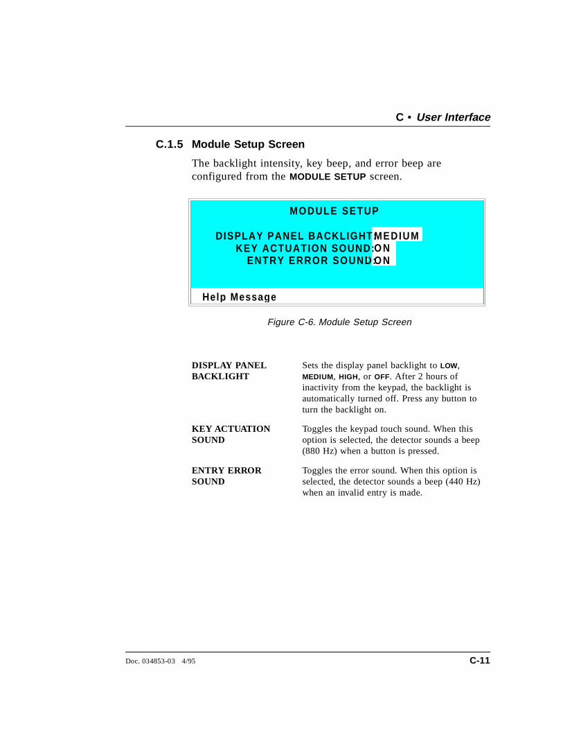
C.1.5 Module Setup Screen
The backlight intensity, key beep, and error beep areconfigured from the MODULE SETUP screen.
DISPLAY PANELBACKLIGHT
Sets the display panel backlight to LOW,MEDIUM, HIGH, or OFF. After 2 hours ofinactivity from the keypad, the backlight isautomatically turned off. Press any button toturn the backlight on.
KEY ACTUATIONSOUND
Toggles the keypad touch sound. When thisoption is selected, the detector sounds a beep(880 Hz) when a button is pressed.
ENTRY ERRORSOUND
Toggles the error sound. When this option isselected, the detector sounds a beep (440 Hz)when an invalid entry is made.
Hel p Messa g e
DISPLAY PANEL BACKLIGHT:KEY ACTUATION SOUND:
ENTRY ERROR SOUND:
MEDIUMO NO N
MODULE SETUP
Figure C-6. Module Setup Screen
C • User Interface
Doc. 034853-03 4/95 C-11
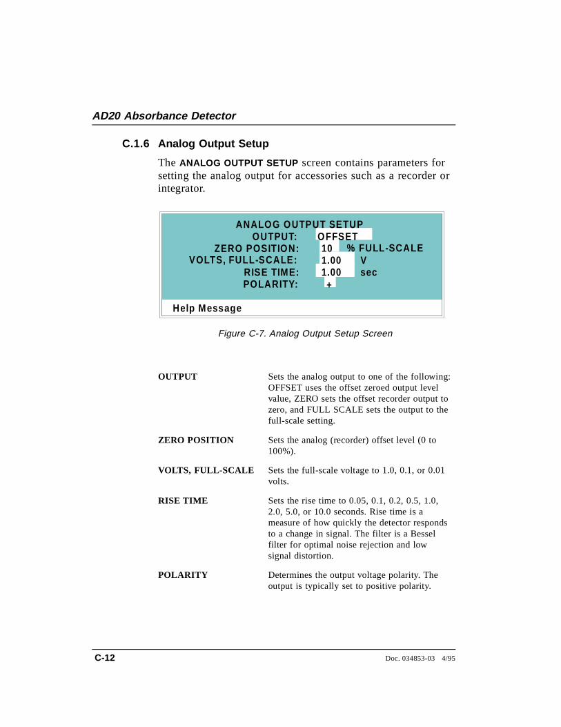
C.1.6 Analog Output Setup
The ANALOG OUTPUT SETUP screen contains parameters forsetting the analog output for accessories such as a recorder orintegrator.
OUTPUT Sets the analog output to one of the following:OFFSET uses the offset zeroed output levelvalue, ZERO sets the offset recorder output tozero, and FULL SCALE sets the output to thefull-scale setting.
ZERO POSITION Sets the analog (recorder) offset level (0 to100%).
VOLTS, FULL-SCALE Sets the full-scale voltage to 1.0, 0.1, or 0.01volts.
RISE TIME Sets the rise time to 0.05, 0.1, 0.2, 0.5, 1.0,2.0, 5.0, or 10.0 seconds. Rise time is ameasure of how quickly the detector respondsto a change in signal. The filter is a Besselfilter for optimal noise rejection and lowsignal distortion.
POLARITY Determines the output voltage polarity. Theoutput is typically set to positive polarity.
Help Messa g e
VOLTS, FULL-SCALE:
OFFSETOUTPUT:10
RISE TIME:POLARITY:
1.001.00
+
% FULL-SCALEVsec
ZERO POSITION:
ANALOG OUTPUT SETUP
Figure C-7. Analog Output Setup Screen
AD20 Absorbance Detector
C-12 Doc. 034853-03 4/95
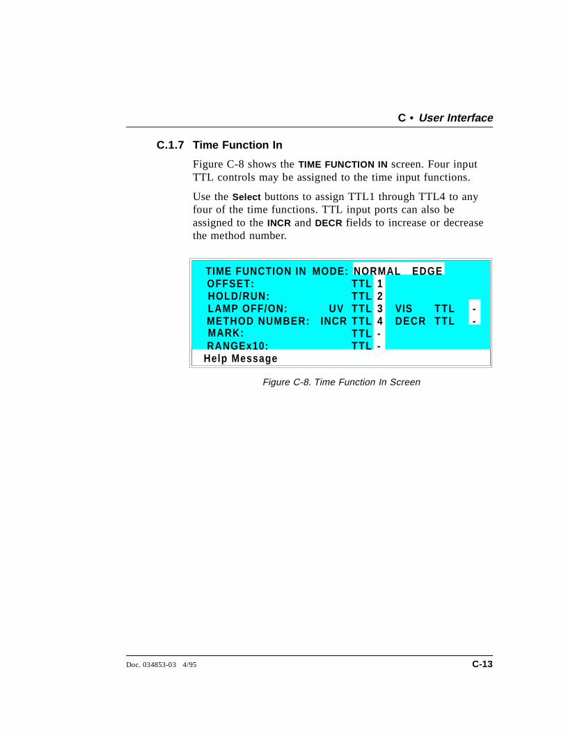
C.1.7 Time Function In
Figure C-8 shows the TIME FUNCTION IN screen. Four inputTTL controls may be assigned to the time input functions.
Use the Select buttons to assign TTL1 through TTL4 to anyfour of the time functions. TTL input ports can also beassigned to the INCR and DECR fields to increase or decreasethe method number.
Help Message
HOLD/RUN:LAMP OFF/ON:METHOD NUMBER:
1234
TIME FUNCTION INOFFSET:
MARK:RANGEx10:
MODE: NORMAL EDGE
--
TTLTTLTTLTTLTTLTTL
TTLTTL
UVINCR DECR
VIS --
Figure C-8. Time Function In Screen
C • User Interface
Doc. 034853-03 4/95 C-13
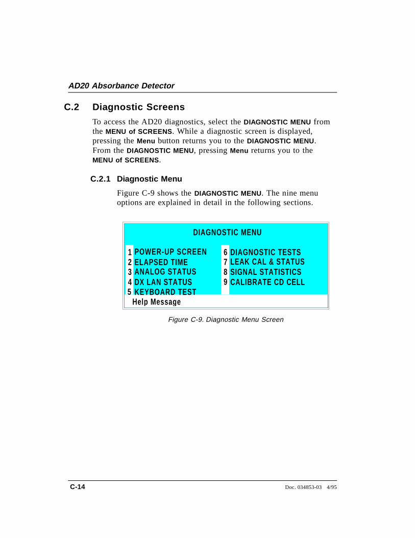
C.2 Diagnostic Screens
To access the AD20 diagnostics, select the DIAGNOSTIC MENU fromthe MENU of SCREENS . While a diagnostic screen is displayed,pressing the Menu button returns you to the DIAGNOSTIC MENU.From the DIAGNOSTIC MENU, pressing Menu returns you to theMENU of SCREENS .
C.2.1 Diagnostic Menu
Figure C-9 shows the DIAGNOSTIC MENU. The nine menuoptions are explained in detail in the following sections.
Help Messa ge
POWER-UP SCREENELAPSED TIMEANALOG STATUS DX LAN STATUS
DIAGNOSTIC TESTSLEAK CAL & STATUSSIGNAL STATISTICSCALIBRATE CD CELL
12345
678
DIAGNOSTIC MENU
KEYBOARD TEST9
Figure C-9. Diagnostic Menu Screen
AD20 Absorbance Detector
C-14 Doc. 034853-03 4/95

C.2.2 Power-Up Screen
This screen displays the revision numbers for the Modulewareand BIOS code. It also displays the identification number ofthe optional DX LAN interface, if connected.
The AD20 conducts a wavelength calibration test uponpower-up. If test results are negative, a warning beep soundsand an error message appears.
• If the error message indicates a deuterium or tungstenlamp failure, test/recalibrate the source from theDIAGNOSTIC TESTS screen. If the message reappears, notifyDionex.
• If the error message indicates a UV or visible wavelengthcalibration failure, turn off the AD20 power for a fewseconds and then turn it back on. If the messagereappears, test/recalibrate the source from the DIAGNOSTIC
TESTS screen. If this does not eliminate the problem,notify Dionex.
Help Message
MODULEWARE REV
AD20 ABSORBANCE DETECTOR
BIOS REV n.nnn.nn
nnnnnnDX LAN ID#
Figure C-10. Power-Up Screen
C • User Interface
Doc. 034853-03 4/95 C-15
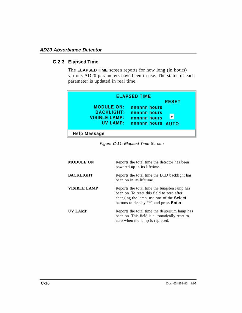
C.2.3 Elapsed Time
The ELAPSED TIME screen reports for how long (in hours)various AD20 parameters have been in use. The status of eachparameter is updated in real time.
MODULE ON Reports the total time the detector has beenpowered up in its lifetime.
BACKLIGHT Reports the total time the LCD backlight hasbeen on in its lifetime.
VISIBLE LAMP Reports the total time the tungsten lamp hasbeen on. To reset this field to zero afterchanging the lamp, use one of the Selectbuttons to display “*” and press Enter .
UV LAMP Reports the total time the deuterium lamp hasbeen on. This field is automatically reset tozero when the lamp is replaced.
Help Message
MODULE ON:
ELAPSED TIME
BACKLIGHT:VISIBLE LAMP:
UV LAMP:
nnnnnn hoursnnnnnn hoursnnnnnn hoursnnnnnn hours
RESET
*AUTO
Figure C-11. Elapsed Time Screen
AD20 Absorbance Detector
C-16 Doc. 034853-03 4/95
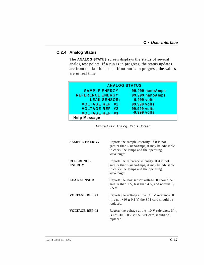
C.2.4 Analog Status
The ANALOG STATUS screen displays the status of severalanalog test points. If a run is in progress, the status updatesare from the last idle state; if no run is in progress, the valuesare in real time.
SAMPLE ENERGY Reports the sample intensity. If it is notgreater than 5 nanoAmps, it may be advisableto check the lamps and the operatingwavelength.
REFERENCEENERGY
Reports the reference intensity. If it is notgreater than 5 nanoAmps, it may be advisableto check the lamps and the operatingwavelength.
LEAK SENSOR Reports the leak sensor voltage. It should begreater than 1 V, less than 4 V, and nominally2.5 V.
VOLTAGE REF #1 Reports the voltage at the +10 V reference. Ifit is not +10 ± 0.1 V, the SP1 card should bereplaced.
VOLTAGE REF #2 Reports the voltage at the -10 V reference. If itis not -10 ± 0.2 V, the SP1 card should bereplaced.
Help Message
ANALOG STATUSSAMPLE ENERGY:
REFERENCE ENERGY:LEAK SENSOR:
99.999 nanoAmps99.999 nanoAmps
9.999 volts99.999 volts
-99.999 volts-9.999 volts
VOLTAGE REF #1:VOLTAGE REF #2:VOLTAGE REF #3:
Figure C-12. Analog Status Screen
C • User Interface
Doc. 034853-03 4/95 C-17

VOLTAGE REF #3 Reports the A/D zero offset voltage. If it is not-1.00 ± 0.02 V, the SP1 card should bereplaced.
AD20 Absorbance Detector
C-18 Doc. 034853-03 4/95
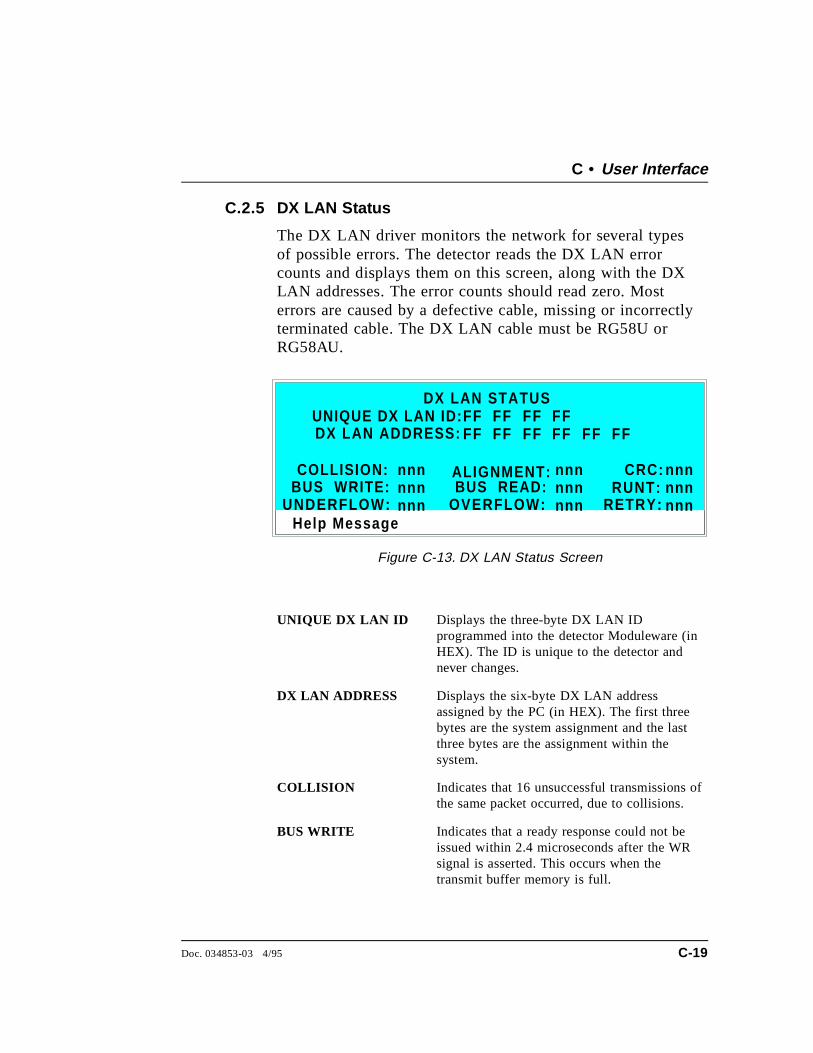
C.2.5 DX LAN Status
The DX LAN driver monitors the network for several typesof possible errors. The detector reads the DX LAN errorcounts and displays them on this screen, along with the DXLAN addresses. The error counts should read zero. Mosterrors are caused by a defective cable, missing or incorrectlyterminated cable. The DX LAN cable must be RG58U orRG58AU.
UNIQUE DX LAN ID Displays the three-byte DX LAN IDprogrammed into the detector Moduleware (inHEX). The ID is unique to the detector andnever changes.
DX LAN ADDRESS Displays the six-byte DX LAN addressassigned by the PC (in HEX). The first threebytes are the system assignment and the lastthree bytes are the assignment within thesystem.
COLLISION Indicates that 16 unsuccessful transmissions ofthe same packet occurred, due to collisions.
BUS WRITE Indicates that a ready response could not beissued within 2.4 microseconds after the WRsignal is asserted. This occurs when thetransmit buffer memory is full.
Help Message
UNIQUE DX LAN ID:DX LAN STATUS
DX LAN ADDRESS:
COLLISION: ALIGNMENT:
UNDERFLOW:BUS WRITE:
nnnnnnnnn
FF FF FF FFFF FF FF FF FF FF
RETRY:
CRC:
OVERFLOW:BUS READ:
nnnnnnnnn
nnnnnnnnn
RUNT:
Figure C-13. DX LAN Status Screen
C • User Interface
Doc. 034853-03 4/95 C-19
UNDERFLOW Indicates that data from the transmit section ofthe hardware buffer memory is not availablefor serial transmission. The DX LAN willcontinue to send out this data frame.
ALIGNMENT Indicates that a packet was received with analignment error, meaning that there were oneto seven extra bits at the end of the packet.This usually indicates a collision or a faultytransceiver.
BUS READ Indicates that a ready response could not beissued within 2.4 microseconds after the readysignal is asserted. This occurs when reading anempty buffer.
OVERFLOW Indicates that the DX LAN hardware receivebuffer became full and had to reject a packetfor lack of space.
CRC Indicates that a packet was received with aCRC error. This usually means that a collisionhas corrupted the packet.
RUNT Indicates that a “runt” packet (one less than 15bytes in length) was received. This usuallyoccurs after a collision has truncated theoriginal length.
RETRY Indicates the number of retries required totransmit the last packet.
AD20 Absorbance Detector
C-20 Doc. 034853-03 4/95

C.2.6 Keyboard Test
You can conduct an interactive test of the AD20 front panelbuttons from the KEYBOARD TEST screen. Pressing any frontpanel button changes the corresponding button indicator onthe screen to reverse video. This confirms proper operation ofthat button. When you release the button, the screen returnsto normal video.
Help Message
OFFSET
MARK
INSERT
DELETE
RUN/HOLD
RESET
SEL UP
SEL DOWN
UP 7 8 9
4 5 6
1 2 3
0 . E
DOWNLEFT RIGHT
HELP MENU
Figure C-14. Keyboard Test Screen
C • User Interface
Doc. 034853-03 4/95 C-21
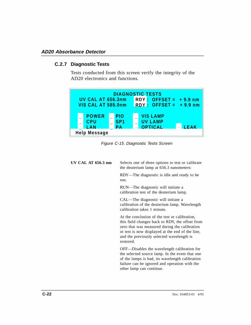
C.2.7 Diagnostic Tests
Tests conducted from this screen verify the integrity of theAD20 electronics and functions.
UV CAL AT 656.3 nm Selects one of three options to test or calibratethe deuterium lamp at 656.3 nanometers:
RDY—The diagnostic is idle and ready to berun.
RUN—The diagnostic will initiate acalibration test of the deuterium lamp.
CAL—The diagnostic will initiate acalibration of the deuterium lamp. Wavelengthcalibration takes 1 minute.
At the conclusion of the test or calibration,this field changes back to RDY, the offset fromzero that was measured during the calibrationor test is now displayed at the end of the line,and the previously selected wavelength isrestored.
OFF—Disables the wavelength calibration forthe selected source lamp. In the event that oneof the lamps is bad, its wavelength calibrationfailure can be ignored and operation with theother lamp can continue.
Help Message
RDY :DIAGNOSTIC TESTS
UV CAL AT 656.3nmRDY :VIS CAL AT 585.0nm
POWERCPULAN
SP1PA
UV LAMPOPTICAL LEAK
___
__
_PIO VIS LAMP__
OFFSET = + 9.9 nmOFFSET = + 9.9 nm
Figure C-15. Diagnostic Tests Screen
AD20 Absorbance Detector
C-22 Doc. 034853-03 4/95
VIS CAL AT 585.0 nm Selects one of three options to test or calibratethe tungsten lamp at 585.0 nanometers:
RDY—The diagnostic is idle and ready to berun.
RUN—The diagnostic will initiate acalibration test of the tungsten lamp.
CAL—The diagnostic will initiate acalibration of the tungsten lamp. Wavelengthcalibration takes 1 minute.
At the conclusion of the test or calibration,this field changes back to RDY, the offset fromzero that was measured during the calibrationor test is now displayed at the end of the line,and the previously selected wavelength isrestored.
OFF—Disables the wavelength calibration forthe selected source lamp. In the event that oneof the lamps is bad, its wavelength calibrationfailure can be ignored and operation with theother lamp can continue.
The following tests can be run from the DIAGNOSTIC TESTSscreen. Select the asterisk (*) in the field beside the name ofthe test and press Enter to immediately begin running the test.When the test is complete, the entry field displays either P(pass) or F (fail).
NOTEThese test and calibration procedures disturb detectorequilibration as the lamps are cycled on and off, and the opticalsystem is cycled through its test modes. After testing, allow thesystem to equilibrate before resuming operation.
• POWER—Checks the +5, ±15, and +24 volt monitor onthe Relay card.
• CPU—Checks the internal CPU configuration andModuleware checksum.
C • User Interface
Doc. 034853-03 4/95 C-23
• LAN—Checks the configuration and loop-back of the DXLAN hardware.
• PIO—Checks the internal monitor against the lampcontrol status.
• SP1—Checks the initialization of control registers, teststhe A/D voltage references, and checks the D/A unit.
• PA—Checks the gain control to the Pre-Amp. This testrequires that the detector have first passed the SP1 test(above).
• VIS LAMP—Turns on the tungsten lamp and checks aninternal PIO monitor. With the optical drawer open, thelamp may be observed.
• UV LAMP—Turns on the deuterium lamp and checks aninternal PIO monitor.
• OPTICAL—Checks the filter wheel position and thevisible zero order (if PA passed).
• LEAK—Checks the correct, open circuit, or short circuitcondition of the leak sensor.
AD20 Absorbance Detector
C-24 Doc. 034853-03 4/95
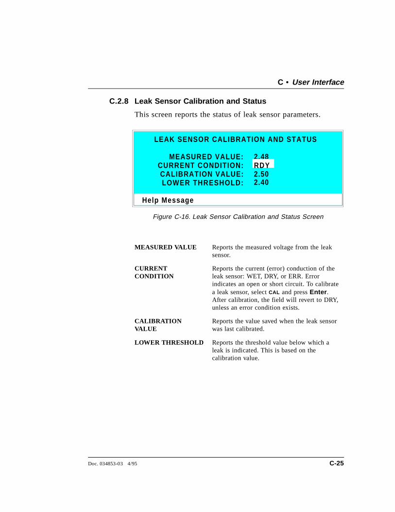
C.2.8 Leak Sensor Calibration and Status
This screen reports the status of leak sensor parameters.
MEASURED VALUE Reports the measured voltage from the leaksensor.
CURRENTCONDITION
Reports the current (error) conduction of theleak sensor: WET, DRY, or ERR. Errorindicates an open or short circuit. To calibratea leak sensor, select CAL and press Enter .After calibration, the field will revert to DRY,unless an error condition exists.
CALIBRATIONVALUE
Reports the value saved when the leak sensorwas last calibrated.
LOWER THRESHOLD Reports the threshold value below which aleak is indicated. This is based on thecalibration value.
Help Message
2.48MEASURED VALUE:RDYCURRENT CONDITION:
CALIBRATION VALUE:LOWER THRESHOLD:
2.502.40
LEAK SENSOR CALIBRATION AND STATUS
Figure C-16. Leak Sensor Calibration and Status Screen
C • User Interface
Doc. 034853-03 4/95 C-25
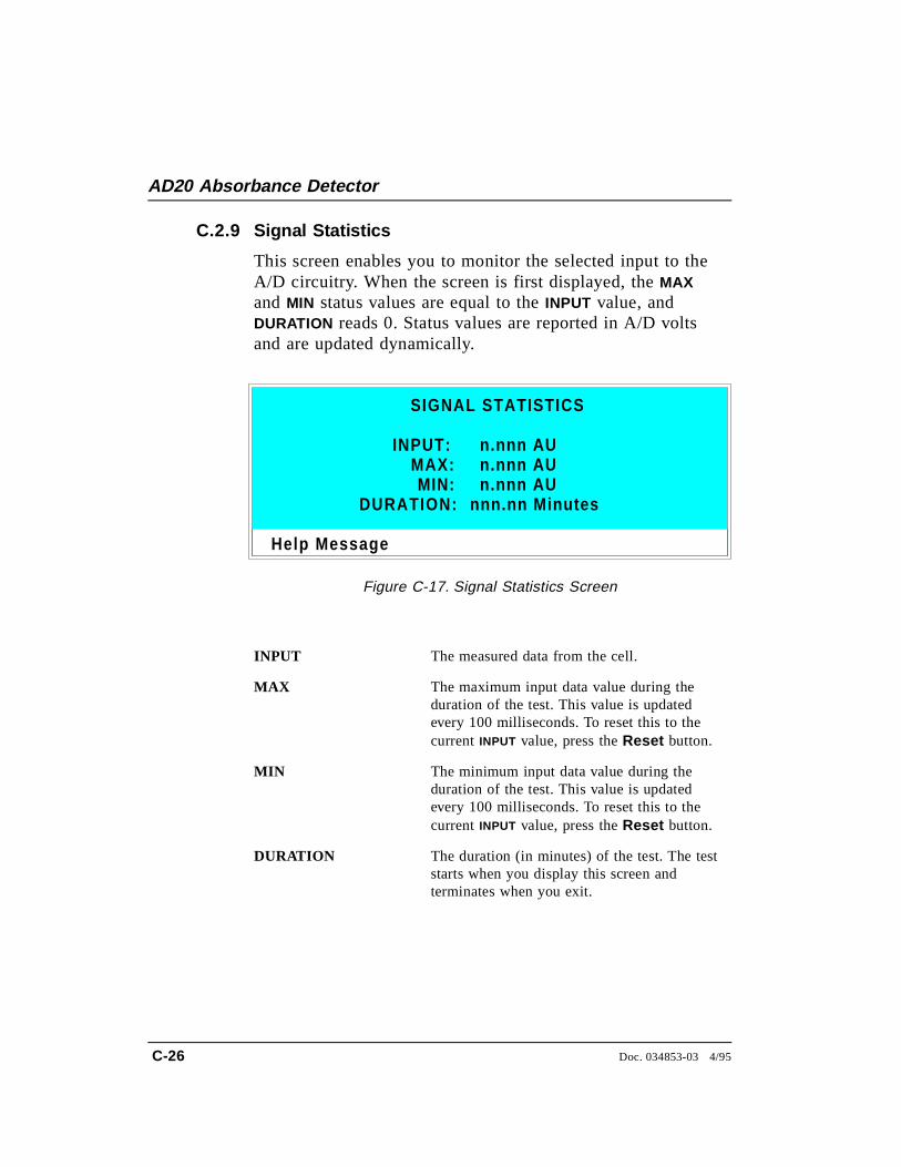
C.2.9 Signal Statistics
This screen enables you to monitor the selected input to theA/D circuitry. When the screen is first displayed, the MAXand MIN status values are equal to the INPUT value, andDURATION reads 0. Status values are reported in A/D voltsand are updated dynamically.
INPUT The measured data from the cell.
MAX The maximum input data value during theduration of the test. This value is updatedevery 100 milliseconds. To reset this to thecurrent INPUT value, press the Reset button.
MIN The minimum input data value during theduration of the test. This value is updatedevery 100 milliseconds. To reset this to thecurrent INPUT value, press the Reset button.
DURATION The duration (in minutes) of the test. The teststarts when you display this screen andterminates when you exit.
Help Message
SIGNAL STATISTICS
INPUT:MAX:
DURATION:MIN:
n.nnn AUn.nnn AU
nnn.nn Minutes
n.nnn AU
Figure C-17. Signal Statistics Screen
AD20 Absorbance Detector
C-26 Doc. 034853-03 4/95
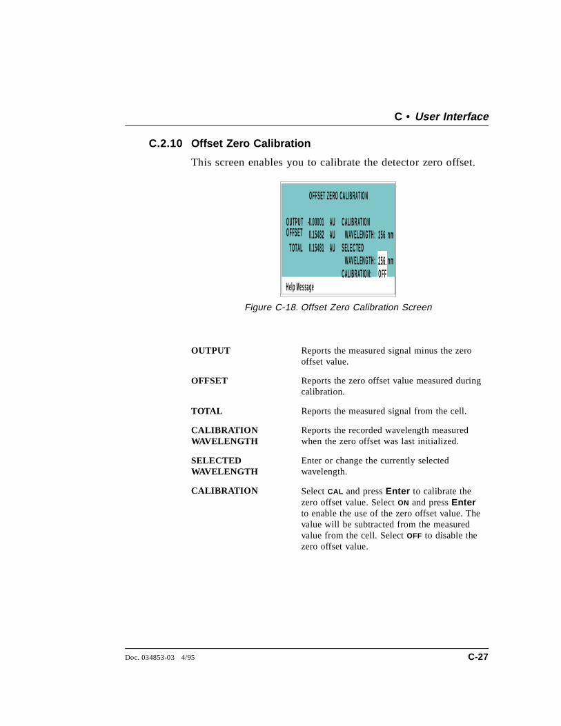
C.2.10 Offset Zero Calibration
This screen enables you to calibrate the detector zero offset.
OUTPUT Reports the measured signal minus the zerooffset value.
OFFSET Reports the zero offset value measured duringcalibration.
TOTAL Reports the measured signal from the cell.
CALIBRATIONWAVELENGTH
Reports the recorded wavelength measuredwhen the zero offset was last initialized.
SELECTEDWAVELENGTH
Enter or change the currently selectedwavelength.
CALIBRATION Select CAL and press Enter to calibrate thezero offset value. Select ON and press Enterto enable the use of the zero offset value. Thevalue will be subtracted from the measuredvalue from the cell. Select OFF to disable thezero offset value.
H el p Messa g e
T OTAL 0 .15481
O FF S ET Z E RO CA L IB RATIO N
O U TP U TO F FS E T 0 .15482
-0 .00001 AUAUAU
WAV E L EN G TH : 256 n mC AL IB R AT IO N : O F F
S EL E C TE DWAV E L EN G TH : 256 n m
C AL IB R AT IO N
Figure C-18. Offset Zero Calibration Screen
C • User Interface
Doc. 034853-03 4/95 C-27

AD20 Absorbance Detector
C-28 Doc. 034853-03 4/95

D • Common Mobile Phases
Doc. 034853-03 4/95 D-1

AD20 Absorbance Detector
D-2 Doc. 034853-03 4/95
D • Common Mobile Phases
D.1 Properties of Common Mobile Phases
The composition of a mobile phase affects its UV cutoff. In general,ion chromatography eluents are mixtures of water and salts such asNa2CO3, NaOH, or HCl. They may also contain acetonitrile ormethanol. Hexane sulfonic acid and tetrabutylammonium hydroxideare also used for some applications. The UV cutoffs of thesesolvents may differ from those predicted by Table D-1 on thefollowing page. The cutoffs listed in the table apply tospectro-quality grade solvents.
Doc. 034853-03 4/95 D-3
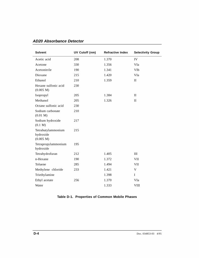
Solvent UV Cutoff (nm) Refractive Index Selectivity Group
Acetic acid 208 1.370 IV
Acetone 330 1.356 VIa
Acetonitrile 190 1.341 VIb
Dioxane 215 1.420 VIa
Ethanol 210 1.359 II
Hexane sulfonic acid(0.005 M)
230
Isopropyl 205 1.384 II
Methanol 205 1.326 II
Octane sulfonic acid 230
Sodium carbonate (0.01 M)
210
Sodium hydroxide (0.1 M)
217
Tetrabutylammoniumhydroxide (0.005 M)
215
Tetrapropylammoniumhydroxide
195
Tetrahydrofuran 212 1.405 III
n-Hexane 190 1.372 VII
Toluene 285 1.494 VII
Methylene chloride 233 1.421 V
Triethylamine 1.398 I
Ethyl acetate 256 1.370 VIa
Water 1.333 VIII
Table D-1. Properties of Common Mobile Phases
AD20 Absorbance Detector
D-4 Doc. 034853-03 4/95

Index
AAD20 Absorbance Detector
Control by/of another instrument, 3-13Dimensions, A-3Height in units, B-4Lifting requirements, B-5Manual conventions, 1-4Operating features, 1-3Replacement parts, 5-3Securing to DX 500 modules, B-4Self-diagnostics, 3-5Shipping requirements, B-6Shutdown procedure, 3-14Specifications, A-3, A-5Theory of operation, 2-21Time in use, C-16Unpacking instructions, B-5Weight, A-3
Analog output settings, A-3Analog test points, C-17Arrow buttons, 2-5, 2-8Asterisk, C-10, C-23Autozero, 4-7
BBattery, lithium, 3-14Beep
Invalid entry, C-11Keypad, 2-5, C-11Wavelength calibration test, C-15
Beer-Lamberts Law, 2-21BIOS, 2-13
Revision number, 3-6, C-15Blank card, 2-12Bolts, shipping, B-5
CCable connections
Routing, 2-10Cable, DX LAN, 4-8
Extension cable, B-13Installation, B-12Specifications, C-19Terminator plugs, 4-8
Campbell, Ian D., 2-22Cards
Location, 2-10See also Name of cardServicing of, 2-10
Cell, 2-14Air bubble removal, 5-4Backpressure line, 5-4, B-8Backpressure regulator, 5-4, B-8Cleaning procedure, 5-3Cleaning the window, B-7Operating pressure, 2-14Path length, A-5Prevention of air bubbles, B-8Tubing connections, B-7Volume, A-5
Circuitry, A/D, C-26Columns
Cleaning, 4-5Connections to the cell, B-7Connections to the flow cell, B-7
Control modes, 2-19See Direct control modeSee Method control mode
CPU card, 2-13Lithium battery, 3-14
Cursor buttons, 2-8Cursor movement, 2-5, 2-8 - 2-9
Doc. 034853-03 4/95 Index-1
DDetection, photometric, 2-22Detector interface card, 2-10, 2-13
Installation, B-12Detector specifications, A-4Deuterium lamp, 2-16
Calibration, 5-7, C-22Lamp does not light, 4-7Life expectancy, 2-16Output waning, 4-4Replacing, 5-6Testing, C-22Time in use, C-16Warm-up period, 4-4Wavelength range, C-5
Diagnostic Menu, C-14Diagnostic screens, 2-8Diagnostics, 4-9
Accessing, C-14Power-up, 3-5 - 3-6
Direct control mode, 2-19, 3-7Selecting, 2-19
DisplayBacklight adjustment, C-11Screen contrast, 2-4
Dwek, Raymond A., 2-22DX 500 systems
Enclosures, 2-3Installation, 2-3, B-4Manuals, 1-6Stacking, B-4
DX LAN card, 2-13DX LAN network, 2-10
Card, 2-13Connector on rear panel, 4-8Error messages, C-19Faulty communication, 4-8Identification number, C-15Installation, B-12Remote operation, 3-13
EElectrical specifications, A-3Electromagnetic interference (EMI), 2-11 - 2-12Electronics, 2-10
Repair of, 5-3Electrostatic discharge (ESD), 2-10Equilibration, system, 4-4 - 4-5Errors
See Troubleshooting
FFields
Blank, 2-7Reverse video, 2-5
Fittings, ferrule, 4-4, 5-3Flow cell
See CellFront panel, 2-4
Adjusting the position, 2-4Front panel buttons
Description, 2-5 - 2-9Testing, C-21
Fuses, 2-10, A-3Replacing, 5-4
HHeat exchanger, 2-15
Backpressure specification, B-9Disposal, 2-15Pressure, 2-15Volume, A-5
Humidity, operating, A-3
IIEC 1010, 1-4Installation instructions, B-6Installation site, A-3, B-3Integrators, 2-17, B-9
Analog output setting, C-12
AD20 Absorbance Detector
Index-2 Doc. 034853-03 4/95
KKeyboard test, C-21Keypad, 2-5
LLamps, 1-3
See Deuterium lampSee Tungsten lamp
Leak sensor, 2-14Current condition, C-25Diagnostic test, C-24Voltage, C-17
Leak tray, 2-14Leaks
Eliminating, 5-3Liquid leaks, 3-14Local mode, 2-17Locked Remote mode, 2-18
MMaintenance procedures, 3-14Manual conventions, 1-4Manuals, DX 500, 1-6Menu of Screens, C-4Menu screens
Overview, C-3Selecting options, C-4
Method clockElapsed time, 3-12
Method controlChanging parameters, 2-20Parameters controlled by, 2-19Selecting, 2-20, 3-8
Method control mode, 2-19, 3-8Method steps, 2-20
Adding, 3-11Blank field, 3-9 - 3-10Chronological order, 3-11Creating, 3-10Deleting, 3-11Initial conditions, 3-9Maximum number, 3-10Time 0.0, 3-9Time field, 3-9
Viewing additional steps, 3-10Methods, 2-5, 3-8
Adding a step, 3-11Changing, 3-10 - 3-11Creating, 2-20, 3-9Deleting, 3-11Deleting a step, 3-11Downloading from PeakNet, 2-18Editing, 2-20, 3-10 - 3-11Editing changes take effect, 2-20Number in memory, 2-21Parameters controlled by, 2-19Programming, 2-20Relay control, 3-13Running a different method, 3-13Running a method, 3-12Saving, 3-10Saving changes, 3-12Step maximum, 3-10TTL control, 3-13
Mobile phasespH, 3-4Preparation, 3-3Reservoirs, 3-4UV cutoff, D-3
Modes of controlSee also Direct control modeSee also Method control mode
Modes of operationSee Operating modes
Moduleware, 2-13, 4-9Revision number, 3-6, C-15Updates, 2-13
OOffset level, C-12Operating modes, 2-17 - 2-18Operation
Automated control, 1-3, 2-18, 3-13Operational screens, 2-8Optical chassis, 2-3
Components, 2-13Drawer, 2-13
Index
Doc. 034853-03 4/95 Index-3
PPassivation, 3-5, 3-14PeakNet Software, 1-3, 2-10, 2-13, 2-18
Method downloading, 2-18Method steps, 3-10
PeakNet Workstation, 3-13Photodiode assembly, 2-14Photometric detection, 2-21PIO card, 2-12Polarity, C-12Power supply, 2-9
Service of, 2-11Status, 2-13
Power Supply card, 2-11Power switch, 2-4
Actuator, 2-4Power-up diagnostics
See also DiagnosticsPower-up tests
Lamp failure, C-15Wavelength calibration, C-15
Pre-amp, 2-12Printed circuit boards
See CardsProblems
See Troubleshooting
RRear panel description, 2-9Recorders
Analog output setting, C-12Connections, B-9
Reference intensity, C-17Relay card, 2-13
Diagnostic test, C-23Relay control, 3-13
Connections, B-10Remote mode, 2-18Repair procedures
See Service proceduresRise time, C-12Run time, C-9
SSafety requirements, 1-4Sample intensity, C-17Screen contrast, 2-4Screens
Diagnostic, C-3Operational, C-3
Screens, diagnostic, C-14Select buttons, 2-5, 2-8Service procedures
Cleaning the cell, 5-3Deuterium lamp replacement, 5-6Electronic components, 5-3Fuse replacement, 5-4Removing trapped air from the cell, 5-4Tungsten lamp replacement, 5-7
Shoe, B-4Shutdown procedure, 3-14Signal processing card
See SP1 cardSP1 card, 2-12, 4-7, C-17 - C-18Stainless steel systems, 3-5, 3-14
TTemperature, operating, A-3Terminator plugs, B-13Ties, B-4Trace-level analyses, 2-15, 3-4
Cell installation, B-8Trademarks, 1-2Troubleshooting
AD20 does not autozero, 4-7Background absorbance high, 4-6Baseline drift, 4-5Baseline noise, 4-4Detector does not respond, 4-3Diagnostic tests, 4-9See also DiagnosticsDX LAN communication, 4-8Lamp does not light, 4-7Peak size, 4-7Wavelength calibration not working, 4-8
TTL control, 3-13Assigning functions, 2-17, C-13Configuring logic levels, 2-18
AD20 Absorbance Detector
Index-4 Doc. 034853-03 4/95
Connections, B-10Tungsten lamp, 2-15
Calibration, 5-8, C-23Lamp does not light, 4-7Life expectancy, 2-15 - 2-16Output waning, 4-4Replacing, 5-7Testing, C-23Time in use, C-16Warm-up period, 4-4Wavelength range, C-5
VVoltage, full-scale, C-12
WWaste line installation, B-9Wavelength
Calibration, 3-5, 4-8Calibration test, C-15Selection, 3-3, C-5
Index
Doc. 034853-03 4/95 Index-5

AD20 Absorbance Detector
Index-6 Doc. 034853-03 4/95