Embed Size (px)
Citation preview
Model 48i Instruction Manual Gas Filter Correlation CO Analyzer Part Number 101891-00 18Dec2010

© 2007 Thermo Fisher Scientific Inc. All rights reserved. Specifications, terms and pricing are subject to change. Not all products are available in all countries. Please consult your local sales representative for details. Thermo Fisher Scientific Air Quality Instruments 27 Forge Parkway Franklin, MA 02038 1-508-520-0430 www.thermo.com/aqi
Thermo Fisher Scientific WEEE Compliance
WEEE Compliance
This product is required to comply with the European Union’s Waste Electrical & Electronic Equipment (WEEE) Directive 2002/96/EC. It is marked with the following symbol:
Thermo Fisher Scientific has contracted with one or more recycling/disposal companies in each EU Member State, and this product should be disposed of or recycled through them. Further information on Thermo Fisher Scientific’s compliance with these Directives, the recyclers in your country, and information on Thermo Fisher Scientific products which may assist the detection of substances subject to the RoHS Directive are available at: www.thermo.com/WEEERoHS.

Thermo Fisher Scientific WEEE Compliance
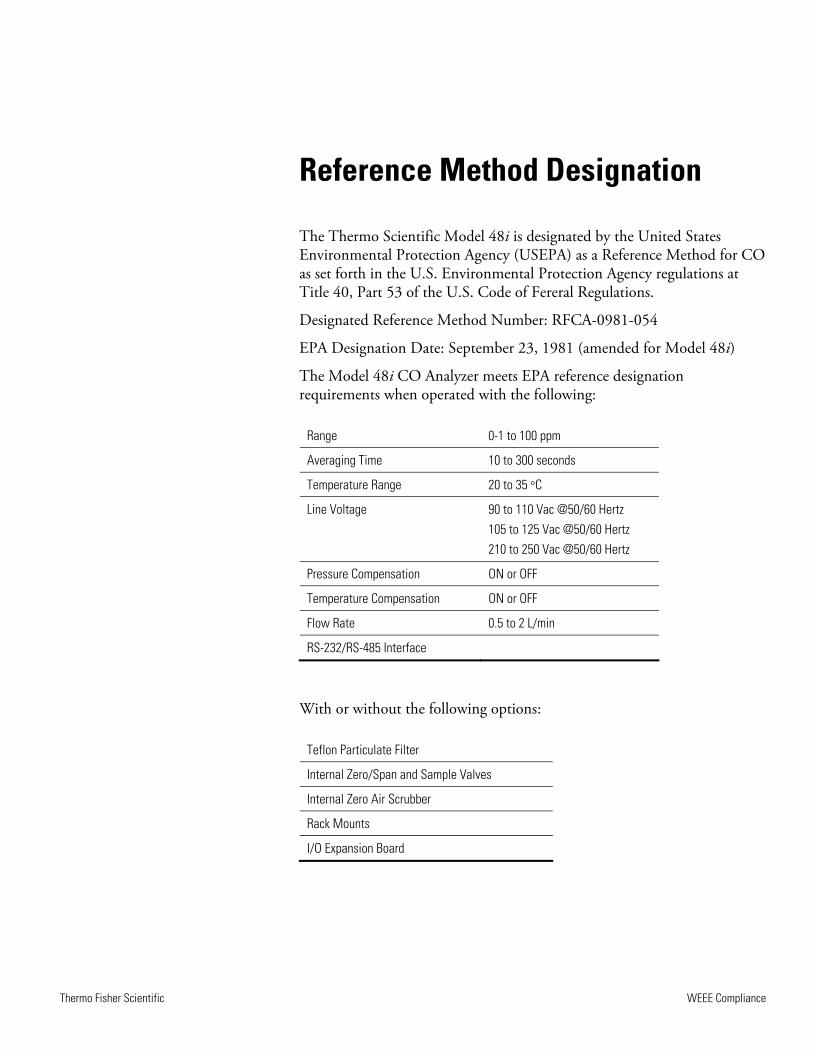
Reference Method Designation
The Thermo Scientific Model 48i is designated by the United States Environmental Protection Agency (USEPA) as a Reference Method for CO as set forth in the U.S. Environmental Protection Agency regulations at Title 40, Part 53 of the U.S. Code of Fereral Regulations.
Designated Reference Method Number: RFCA-0981-054
EPA Designation Date: September 23, 1981 (amended for Model 48i)
The Model 48i CO Analyzer meets EPA reference designation requirements when operated with the following:
Range 0-1 to 100 ppm
Averaging Time 10 to 300 seconds
Temperature Range 20 to 35 °C
Line Voltage 90 to 110 Vac @50/60 Hertz 105 to 125 Vac @50/60 Hertz 210 to 250 Vac @50/60 Hertz
Pressure Compensation ON or OFF
Temperature Compensation ON or OFF
Flow Rate 0.5 to 2 L/min
RS-232/RS-485 Interface
With or without the following options:
Teflon Particulate Filter
Internal Zero/Span and Sample Valves
Internal Zero Air Scrubber
Rack Mounts
I/O Expansion Board

Thermo Fisher Scientific Model 48i Instruction Manual i
About This Manual
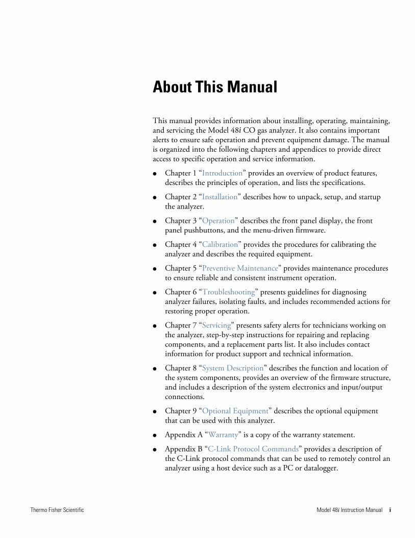
This manual provides information about installing, operating, maintaining, and servicing the Model 48i CO gas analyzer. It also contains important alerts to ensure safe operation and prevent equipment damage. The manual is organized into the following chapters and appendices to provide direct access to specific operation and service information.
● Chapter 1 “Introduction” provides an overview of product features, describes the principles of operation, and lists the specifications.
● Chapter 2 “Installation” describes how to unpack, setup, and startup the analyzer.
● Chapter 3 “Operation” describes the front panel display, the front panel pushbuttons, and the menu-driven firmware.
● Chapter 4 “Calibration” provides the procedures for calibrating the analyzer and describes the required equipment.
● Chapter 5 “Preventive Maintenance” provides maintenance procedures to ensure reliable and consistent instrument operation.
● Chapter 6 “Troubleshooting” presents guidelines for diagnosing analyzer failures, isolating faults, and includes recommended actions for restoring proper operation.
● Chapter 7 “Servicing” presents safety alerts for technicians working on the analyzer, step-by-step instructions for repairing and replacing components, and a replacement parts list. It also includes contact information for product support and technical information.
● Chapter 8 “System Description” describes the function and location of the system components, provides an overview of the firmware structure, and includes a description of the system electronics and input/output connections.
● Chapter 9 “Optional Equipment” describes the optional equipment that can be used with this analyzer.
● Appendix A “Warranty” is a copy of the warranty statement.
● Appendix B “C-Link Protocol Commands” provides a description of the C-Link protocol commands that can be used to remotely control an analyzer using a host device such as a PC or datalogger.
About This Manual Safety
ii Model 48i Instruction Manual Thermo Fisher Scientific
● Appendix C “MODBUS Protocol” provides a description of the MODBUS Protocol Interface and is supported both over RS-232/485 (RTU protocol) as well as TCP/IP over Ethernet.
● Appendix D “Gesytec (Bayern-Hessen) Protocol” provides a description of the Gesytec (Bayern-Hessen or BH) Protocol Interface and is supported both over RS-232/485 as well as TCP/IP over Ethernet.
Review the following safety information carefully before using the analyzer. This manual provides specific information on how to operate the analyzer, however, if the analyzer is used in a manner not specified by the manufacturer, the protection provided by the equipment may be impaired.
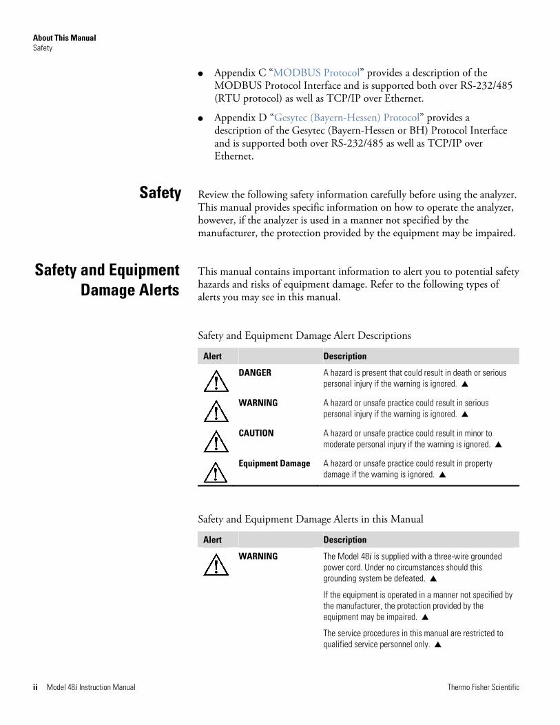
This manual contains important information to alert you to potential safety hazards and risks of equipment damage. Refer to the following types of alerts you may see in this manual.
Safety and Equipment Damage Alert Descriptions
Alert Description
DANGER A hazard is present that could result in death or serious personal injury if the warning is ignored. ▲
WARNING A hazard or unsafe practice could result in serious personal injury if the warning is ignored. ▲
CAUTION A hazard or unsafe practice could result in minor to moderate personal injury if the warning is ignored. ▲
Equipment Damage A hazard or unsafe practice could result in property damage if the warning is ignored. ▲
Safety and Equipment Damage Alerts in this Manual
Alert Description
WARNING The Model 48i is supplied with a three-wire grounded power cord. Under no circumstances should this grounding system be defeated. ▲
If the equipment is operated in a manner not specified by the manufacturer, the protection provided by the equipment may be impaired. ▲
The service procedures in this manual are restricted to qualified service personnel only. ▲
Safety
Safety and Equipment Damage Alerts
About This Manual FCC Compliance
Thermo Fisher Scientific Model 48i Instruction Manual iii
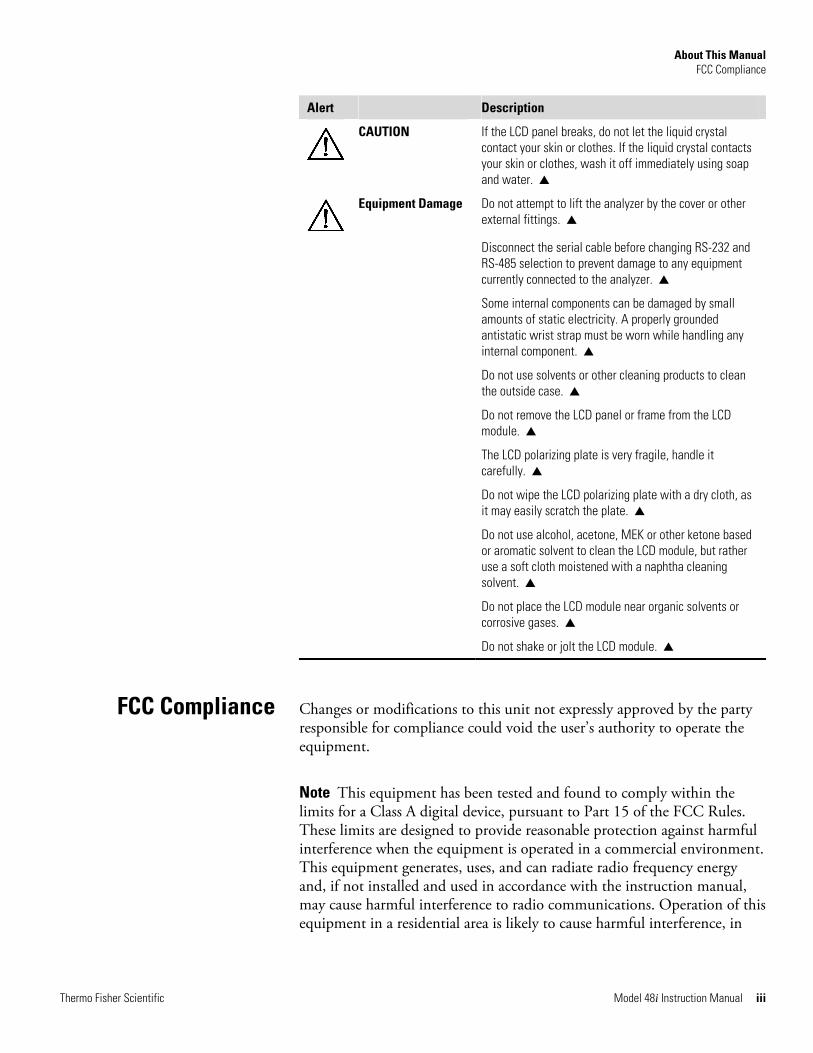
Alert Description
CAUTION If the LCD panel breaks, do not let the liquid crystal contact your skin or clothes. If the liquid crystal contacts your skin or clothes, wash it off immediately using soap and water. ▲
Equipment Damage Do not attempt to lift the analyzer by the cover or other external fittings. ▲
Disconnect the serial cable before changing RS-232 and RS-485 selection to prevent damage to any equipment currently connected to the analyzer. ▲
Some internal components can be damaged by small amounts of static electricity. A properly grounded antistatic wrist strap must be worn while handling any internal component. ▲
Do not use solvents or other cleaning products to clean the outside case. ▲
Do not remove the LCD panel or frame from the LCD module. ▲
The LCD polarizing plate is very fragile, handle it carefully. ▲
Do not wipe the LCD polarizing plate with a dry cloth, as it may easily scratch the plate. ▲
Do not use alcohol, acetone, MEK or other ketone based or aromatic solvent to clean the LCD module, but rather use a soft cloth moistened with a naphtha cleaning solvent. ▲
Do not place the LCD module near organic solvents or corrosive gases. ▲
Do not shake or jolt the LCD module. ▲
Changes or modifications to this unit not expressly approved by the party responsible for compliance could void the user’s authority to operate the equipment.
Note This equipment has been tested and found to comply within the limits for a Class A digital device, pursuant to Part 15 of the FCC Rules. These limits are designed to provide reasonable protection against harmful interference when the equipment is operated in a commercial environment. This equipment generates, uses, and can radiate radio frequency energy and, if not installed and used in accordance with the instruction manual, may cause harmful interference to radio communications. Operation of this equipment in a residential area is likely to cause harmful interference, in
FCC Compliance
About This Manual WEEE Symbol
iv Model 48i Instruction Manual Thermo Fisher Scientific
which case the user will be required to correct the interference at his or her own expense. ▲
The following symbol and description identify the WEEE marking used on the instrument and in the associated documentation.
Symbol Description
Marking of electrical and electronic equipment which applies to waste electrical and electronic equipment falling under the Directive 2002/96/EC (WEEE) and the equipment that has been put on the market after 13 August 2005. ▲
Service is available from exclusive distributors worldwide. Contact one of the phone numbers below for product support and technical information or visit us on the web at www.thermo.com/aqi.
1-866-282-0430 Toll Free
1-508-520-0430 International
WEEE Symbol
Where to Get Help
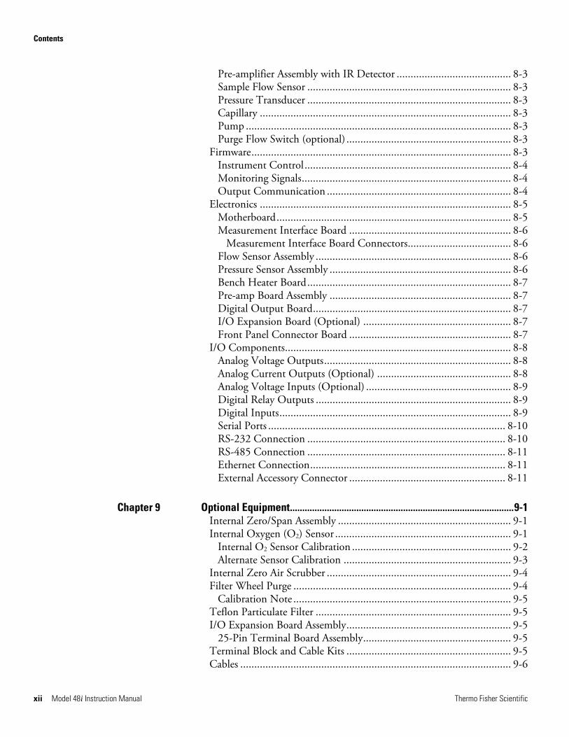
Contents
Thermo Fisher Scientific Model 48i Instruction Manual v
Contents Introduction........................................................................................................ 1-1
Principle of Operation ........................................................................ 1-2 Specifications ...................................................................................... 1-3
Installation ......................................................................................................... 2-1 Lifting................................................................................................. 2-1 Unpacking and Inspection .................................................................. 2-1 Setup Procedure .................................................................................. 2-3 Connecting External Devices .............................................................. 2-5
Terminal Board PCB Assemblies...................................................... 2-5 I/O Terminal Board...................................................................... 2-5 D/O Terminal Board .................................................................... 2-7 25-Pin Terminal Board ................................................................. 2-8
Startup ................................................................................................ 2-9
Operation............................................................................................................ 3-1 Display................................................................................................ 3-1 Pushbuttons ........................................................................................ 3-2
Soft Keys.......................................................................................... 3-3 Alphanumeric Entry Screen ............................................................. 3-4
Firmware Overview............................................................................. 3-4 Power-Up Screen ............................................................................. 3-6 Run Screen....................................................................................... 3-6
Custom Run Screens..................................................................... 3-7 Main Menu...................................................................................... 3-8
Range Menu ....................................................................................... 3-8 Single Range Mode .......................................................................... 3-9 Dual Range Mode.......................................................................... 3-10 Auto Range Mode.......................................................................... 3-11 Gas Units ....................................................................................... 3-13 CO Range...................................................................................... 3-14 Set Custom Ranges ........................................................................ 3-15
Custom Ranges ........................................................................... 3-15 Averaging Time................................................................................. 3-16 Calibration Factors Menu ................................................................. 3-16
CO Background............................................................................. 3-17 CO Coefficient .............................................................................. 3-18 O2 Background .............................................................................. 3-18 O2 Coefficient................................................................................ 3-19
Chapter 1
Chapter 2
Chapter 3
Contents
vi Model 48i Instruction Manual Thermo Fisher Scientific
Reset User Calibration Defaults ..................................................... 3-20 Calibration Menu ............................................................................. 3-20
Calibrate CO Background.............................................................. 3-21 Calibrate CO Coefficient ............................................................... 3-21 Zero/Span Check ........................................................................... 3-22
Next Time .................................................................................. 3-22 Period Hours............................................................................... 3-23 Total Duration Hour .................................................................. 3-23 Zero/Span/Purge Duration Minutes ........................................... 3-23 Zero/Span Averaging Time ......................................................... 3-24 Zero/Span Calibration Reset ....................................................... 3-24 Zero/Span Ratio.......................................................................... 3-24
Calibrate O2 Background ............................................................... 3-25 Calibrate O2 Coefficient................................................................. 3-25
Instrument Controls Menu ............................................................... 3-25 Datalogging Settings ...................................................................... 3-26
Select Srec/Lrec ........................................................................... 3-27 View Logged Data....................................................................... 3-27 Number of Records..................................................................... 3-27 Date and Time............................................................................ 3-28 Erase Log .................................................................................... 3-29 Select Content............................................................................. 3-29 Choose Field Data....................................................................... 3-29 Concentrations............................................................................ 3-30 Corrected Concentrations ........................................................... 3-30 Other Measurements................................................................... 3-31 Analog Inputs.............................................................................. 3-31 Commit Content ........................................................................ 3-32 Reset to Default Content ............................................................ 3-32 Configure Datalogging................................................................ 3-33 Logging Period Min .................................................................... 3-33 Memory Allocation Percent......................................................... 3-33 Data Treatment .......................................................................... 3-34 Flag Status Data .......................................................................... 3-34
Communication Settings................................................................ 3-35 Serial Settings.............................................................................. 3-35 Baud Rate ................................................................................... 3-35 Data Bits ..................................................................................... 3-36 Parity .......................................................................................... 3-36 Stop Bits ..................................................................................... 3-36 RS-232/RS-485 Selection............................................................ 3-37 Instrument ID............................................................................. 3-37 Gesytec Serial No........................................................................ 3-38 Communication Protocol............................................................ 3-38 Streaming Data Configuration .................................................... 3-39 Streaming Data Interval .............................................................. 3-40
Contents
Thermo Fisher Scientific Model 48i Instruction Manual vii
Add Labels .................................................................................. 3-40 Prepend Timestamp.................................................................... 3-40 Add Flags .................................................................................... 3-40 Choose Stream Data Item ........................................................... 3-41 Concentrations............................................................................ 3-41 Corrected Concentrations ........................................................... 3-41 Other Measurements................................................................... 3-42 Analog Inputs ............................................................................. 3-42 TCP/IP Settings.......................................................................... 3-43 Use DHCP ................................................................................. 3-43 IP Address................................................................................... 3-44 Netmask ..................................................................................... 3-44 Default Gateway ......................................................................... 3-44 Host Name ................................................................................. 3-45 Network Time Protocol Server.................................................... 3-45
I/O Configuration ......................................................................... 3-45 Output Relay Settings ................................................................. 3-46 Logic State .................................................................................. 3-46 Instrument State ......................................................................... 3-47 Alarms......................................................................................... 3-47 Non-Alarm ................................................................................. 3-48 Digital Input Settings.................................................................. 3-48 Logic State .................................................................................. 3-49 Instrument Action....................................................................... 3-49 Analog Output Configuration (Select Channel) .......................... 3-49 Allow Over/Under Range............................................................ 3-50 Analog Output Configuration (Select Action)............................. 3-50 Select Range................................................................................ 3-51 Minimum and Maximum Value ................................................. 3-51 Choose Signal to Output ............................................................ 3-52 Analog Input Configuration........................................................ 3-54 Descriptor ................................................................................... 3-54 Units........................................................................................... 3-55 Decimal Places ............................................................................ 3-55 Number of Table Points ............................................................. 3-55 Table Point ................................................................................. 3-56 Volts ........................................................................................... 3-56 User Value .................................................................................. 3-57
Temperature Compensation .......................................................... 3-57 Pressure Compensation .................................................................. 3-58 O2 Compensation .......................................................................... 3-58 Screen Contrast.............................................................................. 3-59 Service Mode ................................................................................. 3-59 Date/Time ..................................................................................... 3-60 Timezone....................................................................................... 3-60
Diagnostics Menu ............................................................................. 3-61
Contents
viii Model 48i Instruction Manual Thermo Fisher Scientific
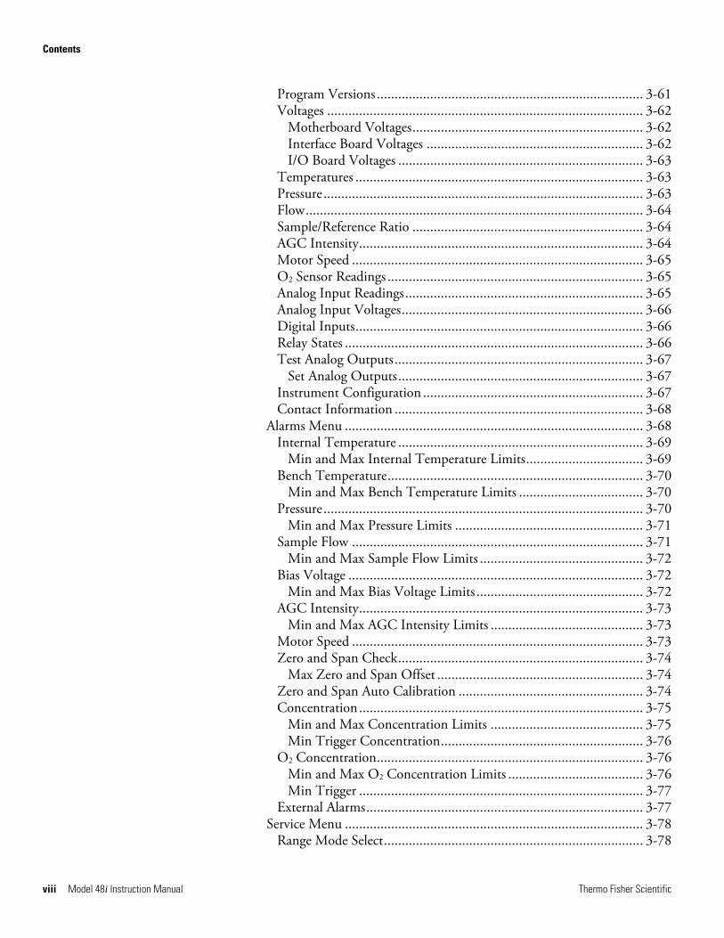
Program Versions ........................................................................... 3-61 Voltages ......................................................................................... 3-62
Motherboard Voltages................................................................. 3-62 Interface Board Voltages ............................................................. 3-62 I/O Board Voltages ..................................................................... 3-63
Temperatures ................................................................................. 3-63 Pressure.......................................................................................... 3-63 Flow............................................................................................... 3-64 Sample/Reference Ratio ................................................................. 3-64 AGC Intensity................................................................................ 3-64 Motor Speed .................................................................................. 3-65 O2 Sensor Readings ........................................................................ 3-65 Analog Input Readings................................................................... 3-65 Analog Input Voltages.................................................................... 3-66 Digital Inputs................................................................................. 3-66 Relay States .................................................................................... 3-66 Test Analog Outputs...................................................................... 3-67
Set Analog Outputs..................................................................... 3-67 Instrument Configuration .............................................................. 3-67 Contact Information ...................................................................... 3-68
Alarms Menu .................................................................................... 3-68 Internal Temperature ..................................................................... 3-69
Min and Max Internal Temperature Limits................................. 3-69 Bench Temperature........................................................................ 3-70
Min and Max Bench Temperature Limits ................................... 3-70 Pressure.......................................................................................... 3-70
Min and Max Pressure Limits ..................................................... 3-71 Sample Flow .................................................................................. 3-71
Min and Max Sample Flow Limits .............................................. 3-72 Bias Voltage ................................................................................... 3-72
Min and Max Bias Voltage Limits ............................................... 3-72 AGC Intensity................................................................................ 3-73
Min and Max AGC Intensity Limits ........................................... 3-73 Motor Speed .................................................................................. 3-73 Zero and Span Check..................................................................... 3-74
Max Zero and Span Offset .......................................................... 3-74 Zero and Span Auto Calibration .................................................... 3-74 Concentration................................................................................ 3-75
Min and Max Concentration Limits ........................................... 3-75 Min Trigger Concentration......................................................... 3-76
O2 Concentration........................................................................... 3-76 Min and Max O2 Concentration Limits ...................................... 3-76 Min Trigger ................................................................................ 3-77
External Alarms.............................................................................. 3-77 Service Menu .................................................................................... 3-78
Range Mode Select......................................................................... 3-78
Contents
Thermo Fisher Scientific Model 48i Instruction Manual ix
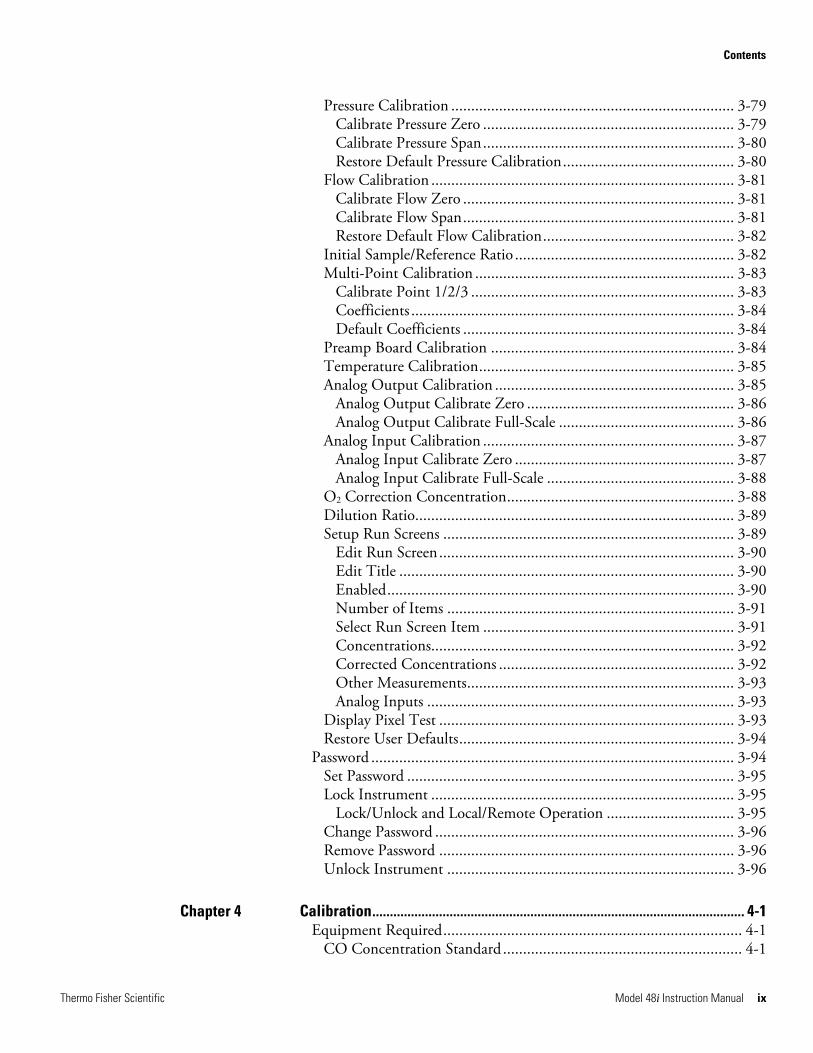
Pressure Calibration ....................................................................... 3-79 Calibrate Pressure Zero ............................................................... 3-79 Calibrate Pressure Span............................................................... 3-80 Restore Default Pressure Calibration........................................... 3-80
Flow Calibration ............................................................................ 3-81 Calibrate Flow Zero .................................................................... 3-81 Calibrate Flow Span.................................................................... 3-81 Restore Default Flow Calibration................................................ 3-82
Initial Sample/Reference Ratio ....................................................... 3-82 Multi-Point Calibration ................................................................. 3-83
Calibrate Point 1/2/3 .................................................................. 3-83 Coefficients ................................................................................. 3-84 Default Coefficients .................................................................... 3-84
Preamp Board Calibration ............................................................. 3-84 Temperature Calibration................................................................ 3-85 Analog Output Calibration ............................................................ 3-85
Analog Output Calibrate Zero .................................................... 3-86 Analog Output Calibrate Full-Scale ............................................ 3-86
Analog Input Calibration ............................................................... 3-87 Analog Input Calibrate Zero ....................................................... 3-87 Analog Input Calibrate Full-Scale ............................................... 3-88
O2 Correction Concentration......................................................... 3-88 Dilution Ratio................................................................................ 3-89 Setup Run Screens ......................................................................... 3-89
Edit Run Screen.......................................................................... 3-90 Edit Title .................................................................................... 3-90 Enabled....................................................................................... 3-90 Number of Items ........................................................................ 3-91 Select Run Screen Item ............................................................... 3-91 Concentrations............................................................................ 3-92 Corrected Concentrations ........................................................... 3-92 Other Measurements................................................................... 3-93 Analog Inputs ............................................................................. 3-93
Display Pixel Test .......................................................................... 3-93 Restore User Defaults..................................................................... 3-94
Password ........................................................................................... 3-94 Set Password .................................................................................. 3-95 Lock Instrument ............................................................................ 3-95
Lock/Unlock and Local/Remote Operation ................................ 3-95 Change Password ........................................................................... 3-96 Remove Password .......................................................................... 3-96 Unlock Instrument ........................................................................ 3-96
Calibration.......................................................................................................... 4-1 Equipment Required........................................................................... 4-1
CO Concentration Standard ............................................................ 4-1
Chapter 4
Contents
x Model 48i Instruction Manual Thermo Fisher Scientific
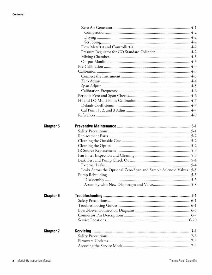
Zero Air Generator........................................................................... 4-1 Compression ................................................................................. 4-2 Drying .......................................................................................... 4-2 Scrubbing...................................................................................... 4-2
Flow Meter(s) and Controller(s)....................................................... 4-2 Pressure Regulator for CO Standard Cylinder.................................. 4-2 Mixing Chamber.............................................................................. 4-3 Output Manifold ............................................................................. 4-3
Pre-Calibration ................................................................................... 4-3 Calibration.......................................................................................... 4-3
Connect the Instrument................................................................... 4-3 Zero Adjust ...................................................................................... 4-4 Span Adjust...................................................................................... 4-5 Calibration Frequency...................................................................... 4-6
Periodic Zero and Span Checks........................................................... 4-6 HI and LO Multi-Point Calibration ................................................... 4-7
Default Coefficients ......................................................................... 4-7 Cal Point 1, 2, and 3 Adjust............................................................. 4-7
References ........................................................................................... 4-9
Preventive Maintenance .................................................................................5-1 Safety Precautions ............................................................................... 5-1 Replacement Parts............................................................................... 5-2 Cleaning the Outside Case .................................................................. 5-2 Cleaning the Optics ............................................................................ 5-2 IR Source Replacement ....................................................................... 5-3 Fan Filter Inspection and Cleaning ..................................................... 5-3 Leak Test and Pump Check Out......................................................... 5-4
External Leaks .................................................................................. 5-4 Leaks Across the Optional Zero/Span and Sample Solenoid Valves .. 5-5
Pump Rebuilding ................................................................................ 5-5 Disassembly .................................................................................. 5-5 Assembly with New Diaphragm and Valve.................................... 5-8
Troubleshooting.................................................................................................6-1 Safety Precautions ............................................................................... 6-1 Troubleshooting Guides...................................................................... 6-1 Board-Level Connection Diagrams ..................................................... 6-5 Connector Pin Descriptions ................................................................ 6-7 Service Locations............................................................................... 6-20
Servicing .............................................................................................................7-1 Safety Precautions ............................................................................... 7-3 Firmware Updates ............................................................................... 7-4 Accessing the Service Mode................................................................. 7-4
Chapter 5
Chapter 6
Chapter 7
Contents
Thermo Fisher Scientific Model 48i Instruction Manual xi
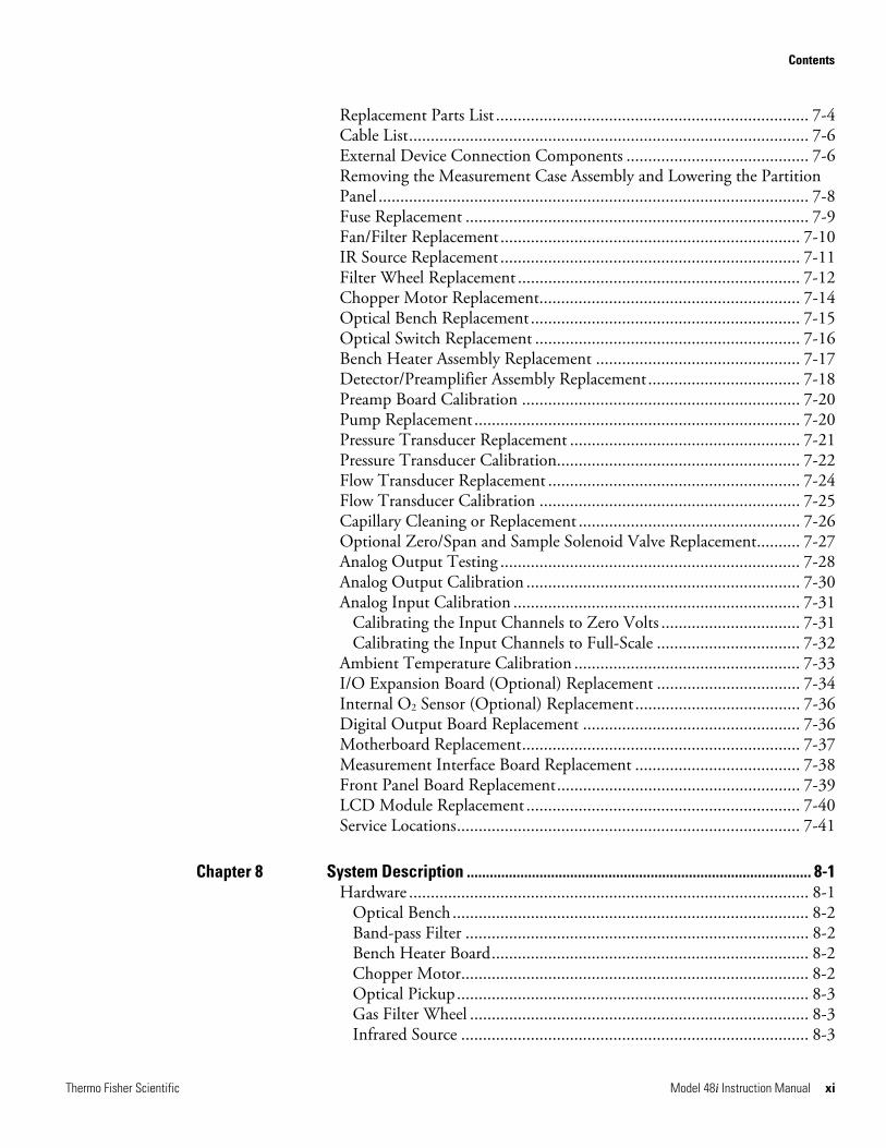
Replacement Parts List ........................................................................ 7-4 Cable List............................................................................................ 7-6 External Device Connection Components .......................................... 7-6 Removing the Measurement Case Assembly and Lowering the Partition Panel ................................................................................................... 7-8 Fuse Replacement ............................................................................... 7-9 Fan/Filter Replacement..................................................................... 7-10 IR Source Replacement ..................................................................... 7-11 Filter Wheel Replacement ................................................................. 7-12 Chopper Motor Replacement............................................................ 7-14 Optical Bench Replacement.............................................................. 7-15 Optical Switch Replacement ............................................................. 7-16 Bench Heater Assembly Replacement ............................................... 7-17 Detector/Preamplifier Assembly Replacement................................... 7-18 Preamp Board Calibration ................................................................ 7-20 Pump Replacement ........................................................................... 7-20 Pressure Transducer Replacement ..................................................... 7-21 Pressure Transducer Calibration........................................................ 7-22 Flow Transducer Replacement .......................................................... 7-24 Flow Transducer Calibration ............................................................ 7-25 Capillary Cleaning or Replacement ................................................... 7-26 Optional Zero/Span and Sample Solenoid Valve Replacement.......... 7-27 Analog Output Testing ..................................................................... 7-28 Analog Output Calibration ............................................................... 7-30 Analog Input Calibration .................................................................. 7-31
Calibrating the Input Channels to Zero Volts ................................ 7-31 Calibrating the Input Channels to Full-Scale ................................. 7-32
Ambient Temperature Calibration .................................................... 7-33 I/O Expansion Board (Optional) Replacement ................................. 7-34 Internal O2 Sensor (Optional) Replacement...................................... 7-36 Digital Output Board Replacement .................................................. 7-36 Motherboard Replacement................................................................ 7-37 Measurement Interface Board Replacement ...................................... 7-38 Front Panel Board Replacement........................................................ 7-39 LCD Module Replacement ............................................................... 7-40 Service Locations............................................................................... 7-41
System Description .......................................................................................... 8-1 Hardware ............................................................................................ 8-1
Optical Bench .................................................................................. 8-2 Band-pass Filter ............................................................................... 8-2 Bench Heater Board......................................................................... 8-2 Chopper Motor................................................................................ 8-2 Optical Pickup................................................................................. 8-3 Gas Filter Wheel .............................................................................. 8-3 Infrared Source ................................................................................ 8-3
Chapter 8
Contents
xii Model 48i Instruction Manual Thermo Fisher Scientific
Pre-amplifier Assembly with IR Detector ......................................... 8-3 Sample Flow Sensor ......................................................................... 8-3 Pressure Transducer ......................................................................... 8-3 Capillary .......................................................................................... 8-3 Pump ............................................................................................... 8-3 Purge Flow Switch (optional) ........................................................... 8-3
Firmware............................................................................................. 8-3 Instrument Control.......................................................................... 8-4 Monitoring Signals........................................................................... 8-4 Output Communication .................................................................. 8-4
Electronics .......................................................................................... 8-5 Motherboard.................................................................................... 8-5 Measurement Interface Board .......................................................... 8-6
Measurement Interface Board Connectors..................................... 8-6 Flow Sensor Assembly ...................................................................... 8-6 Pressure Sensor Assembly ................................................................. 8-6 Bench Heater Board......................................................................... 8-7 Pre-amp Board Assembly ................................................................. 8-7 Digital Output Board....................................................................... 8-7 I/O Expansion Board (Optional) ..................................................... 8-7 Front Panel Connector Board .......................................................... 8-7
I/O Components................................................................................. 8-8 Analog Voltage Outputs................................................................... 8-8 Analog Current Outputs (Optional) ................................................ 8-8 Analog Voltage Inputs (Optional) .................................................... 8-9 Digital Relay Outputs ...................................................................... 8-9 Digital Inputs................................................................................... 8-9 Serial Ports ..................................................................................... 8-10 RS-232 Connection ....................................................................... 8-10 RS-485 Connection ....................................................................... 8-11 Ethernet Connection...................................................................... 8-11 External Accessory Connector ........................................................ 8-11
Optional Equipment...........................................................................................9-1 Internal Zero/Span Assembly .............................................................. 9-1 Internal Oxygen (O2) Sensor ............................................................... 9-1
Internal O2 Sensor Calibration ......................................................... 9-2 Alternate Sensor Calibration ............................................................ 9-3
Internal Zero Air Scrubber .................................................................. 9-4 Filter Wheel Purge .............................................................................. 9-4
Calibration Note .............................................................................. 9-5 Teflon Particulate Filter ...................................................................... 9-5 I/O Expansion Board Assembly........................................................... 9-5
25-Pin Terminal Board Assembly..................................................... 9-5 Terminal Block and Cable Kits ........................................................... 9-5 Cables ................................................................................................. 9-6
Chapter 9
Contents
Thermo Fisher Scientific Model 48i Instruction Manual xiii
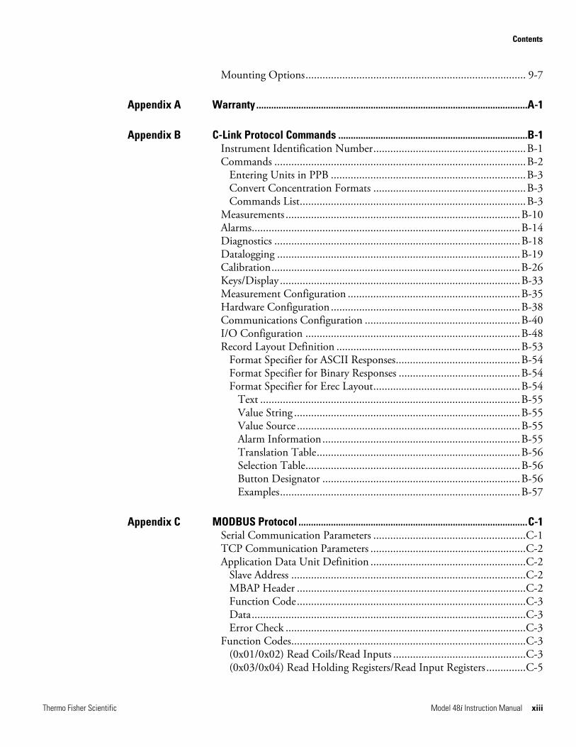
Mounting Options.............................................................................. 9-7
Warranty .............................................................................................................A-1
C-Link Protocol Commands ............................................................................B-1 Instrument Identification Number......................................................B-1 Commands .........................................................................................B-2
Entering Units in PPB .....................................................................B-3 Convert Concentration Formats ......................................................B-3 Commands List................................................................................B-3
Measurements ...................................................................................B-10 Alarms...............................................................................................B-14 Diagnostics .......................................................................................B-18 Datalogging ......................................................................................B-19 Calibration........................................................................................B-26 Keys/Display .....................................................................................B-33 Measurement Configuration .............................................................B-35 Hardware Configuration ...................................................................B-38 Communications Configuration .......................................................B-40 I/O Configuration ............................................................................B-48 Record Layout Definition .................................................................B-53
Format Specifier for ASCII Responses............................................B-54 Format Specifier for Binary Responses ...........................................B-54 Format Specifier for Erec Layout....................................................B-54
Text ............................................................................................B-55 Value String ................................................................................B-55 Value Source ...............................................................................B-55 Alarm Information......................................................................B-55 Translation Table........................................................................B-56 Selection Table............................................................................B-56 Button Designator ......................................................................B-56 Examples.....................................................................................B-57
MODBUS Protocol ............................................................................................C-1 Serial Communication Parameters ......................................................C-1 TCP Communication Parameters .......................................................C-2 Application Data Unit Definition .......................................................C-2
Slave Address ...................................................................................C-2 MBAP Header .................................................................................C-2 Function Code.................................................................................C-3 Data.................................................................................................C-3 Error Check .....................................................................................C-3
Function Codes...................................................................................C-3 (0x01/0x02) Read Coils/Read Inputs ...............................................C-3 (0x03/0x04) Read Holding Registers/Read Input Registers ..............C-5
Appendix A
Appendix B
Appendix C
Contents
xiv Model 48i Instruction Manual Thermo Fisher Scientific
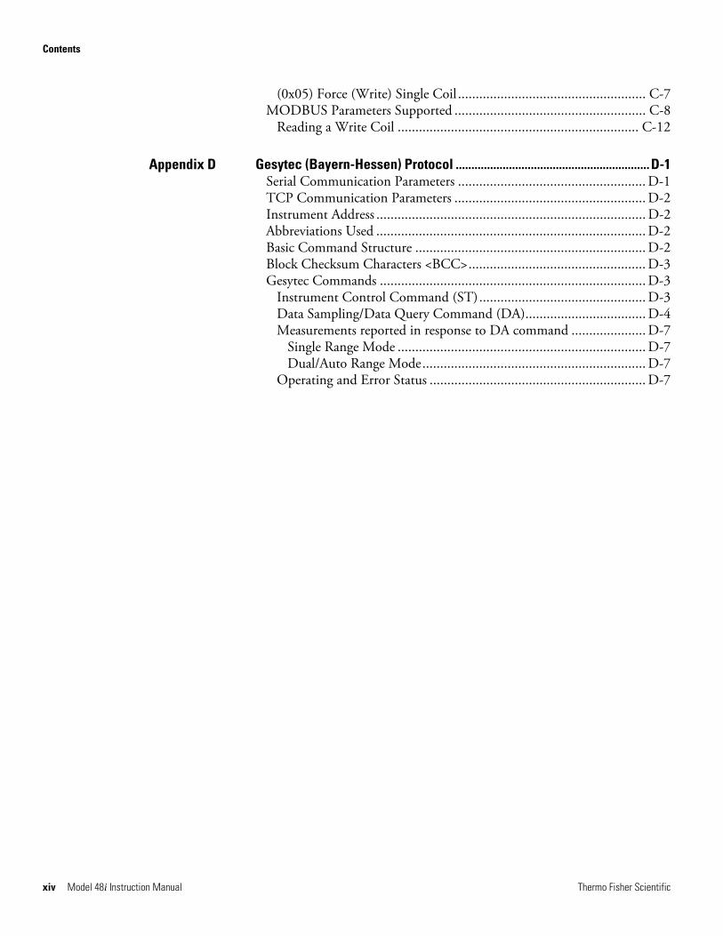
(0x05) Force (Write) Single Coil ..................................................... C-7 MODBUS Parameters Supported ...................................................... C-8
Reading a Write Coil .................................................................... C-12
Gesytec (Bayern-Hessen) Protocol ..............................................................D-1 Serial Communication Parameters ..................................................... D-1 TCP Communication Parameters ...................................................... D-2 Instrument Address ............................................................................ D-2 Abbreviations Used ............................................................................ D-2 Basic Command Structure ................................................................. D-2 Block Checksum Characters <BCC>.................................................. D-3 Gesytec Commands ........................................................................... D-3
Instrument Control Command (ST)............................................... D-3 Data Sampling/Data Query Command (DA).................................. D-4 Measurements reported in response to DA command ..................... D-7
Single Range Mode ...................................................................... D-7 Dual/Auto Range Mode............................................................... D-7
Operating and Error Status ............................................................. D-7
Appendix D
Thermo Fisher Scientific Model 48i Instruction Manual xv
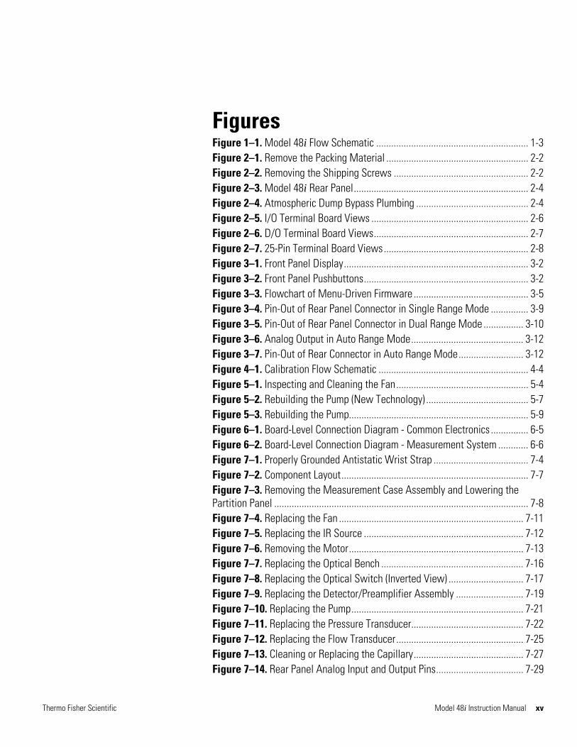
Figures Figure 1–1. Model 48i Flow Schematic ............................................................. 1-3 Figure 2–1. Remove the Packing Material ......................................................... 2-2 Figure 2–2. Removing the Shipping Screws ...................................................... 2-2 Figure 2–3. Model 48i Rear Panel...................................................................... 2-4 Figure 2–4. Atmospheric Dump Bypass Plumbing ............................................. 2-4 Figure 2–5. I/O Terminal Board Views ............................................................... 2-6 Figure 2–6. D/O Terminal Board Views.............................................................. 2-7 Figure 2–7. 25-Pin Terminal Board Views.......................................................... 2-8 Figure 3–1. Front Panel Display.......................................................................... 3-2 Figure 3–2. Front Panel Pushbuttons.................................................................. 3-2 Figure 3–3. Flowchart of Menu-Driven Firmware .............................................. 3-5 Figure 3–4. Pin-Out of Rear Panel Connector in Single Range Mode ............... 3-9 Figure 3–5. Pin-Out of Rear Panel Connector in Dual Range Mode ................ 3-10 Figure 3–6. Analog Output in Auto Range Mode............................................. 3-12 Figure 3–7. Pin-Out of Rear Connector in Auto Range Mode.......................... 3-12 Figure 4–1. Calibration Flow Schematic ............................................................ 4-4 Figure 5–1. Inspecting and Cleaning the Fan..................................................... 5-4 Figure 5–2. Rebuilding the Pump (New Technology) ......................................... 5-7 Figure 5–3. Rebuilding the Pump........................................................................ 5-9 Figure 6–1. Board-Level Connection Diagram - Common Electronics ............... 6-5 Figure 6–2. Board-Level Connection Diagram - Measurement System ............ 6-6 Figure 7–1. Properly Grounded Antistatic Wrist Strap ...................................... 7-4 Figure 7–2. Component Layout........................................................................... 7-7 Figure 7–3. Removing the Measurement Case Assembly and Lowering the Partition Panel ...................................................................................................... 7-8 Figure 7–4. Replacing the Fan .......................................................................... 7-11 Figure 7–5. Replacing the IR Source ................................................................ 7-12 Figure 7–6. Removing the Motor...................................................................... 7-13 Figure 7–7. Replacing the Optical Bench ......................................................... 7-16 Figure 7–8. Replacing the Optical Switch (Inverted View) .............................. 7-17 Figure 7–9. Replacing the Detector/Preamplifier Assembly ........................... 7-19 Figure 7–10. Replacing the Pump..................................................................... 7-21 Figure 7–11. Replacing the Pressure Transducer............................................. 7-22 Figure 7–12. Replacing the Flow Transducer................................................... 7-25 Figure 7–13. Cleaning or Replacing the Capillary............................................ 7-27 Figure 7–14. Rear Panel Analog Input and Output Pins................................... 7-29
Figures
xvi Model 48i Instruction Manual Thermo Fisher Scientific
Figure 7–15. Replacing the I/O Expansion Board (Optional) ............................7-35 Figure 7–16. Rear Panel Board Connectors ......................................................7-35 Figure 7–17. Replacing the Measurement Interface Board .............................7-39 Figure 7–18. Replacing the Front Panel Board and the LCD Module...............7-40 Figure 8–1. Hardware Components ....................................................................8-2 Figure 9–1. Flow Diagram, Internal O2 Sensor ...................................................9-2 Figure 9–2. Purge Housing Assembly .................................................................9-4 Figure 9–3. Rack Mount Option Assembly .........................................................9-8 Figure 9–4. Bench Mounting...............................................................................9-9 Figure 9–5. EIA Rack Mounting ........................................................................9-10 Figure 9–6. Retrofit Rack Mounting..................................................................9-11 Figure B–1. Flags Field......................................................................................B-13
Thermo Fisher Scientific Model 48i Instruction Manual xvii
Tables Table 1–1. Model 48i Specifications ................................................................. 1-3 Table 1–2. Model 48i Optional Internal Oxygen Sensor Specifications ........... 1-4 Table 2–1. I/O Terminal Board Pin Descriptions ................................................ 2-6 Table 2–2. D/O Terminal Board Pin Descriptions............................................... 2-7 Table 2–3. 25-Pin Terminal Board Pin Descriptions........................................... 2-8 Table 3–1. Front Panel Pushbuttons ................................................................... 3-3 Table 3–2. Default Analog Outputs in Single Range Mode............................... 3-9 Table 3–3. Default Analog Outputs in Dual Range Mode ............................... 3-11 Table 3–4. Default Analog Outputs in Auto Range Mode ............................... 3-13 Table 3–5. Available Operating Ranges........................................................... 3-14 Table 3–6. Analog Output Zero to Full-Scale Table ......................................... 3-52 Table 3–7. Signal Type Group Choices............................................................. 3-53 Table 6–1. Troubleshooting - General Guide ..................................................... 6-2 Table 6–2. Troubleshooting - Alarm Messages ................................................. 6-3 Table 6–3. Motherboard Connector Pin Descriptions........................................ 6-7 Table 6–4. Measurement Interface Board Connector Pin Descriptions .......... 6-12 Table 6–5. Front Panel Board Connector Pin Diagram..................................... 6-14 Table 6–6. I/O Expansion Board (Optional) Connector Pin Descriptions ......... 6-16 Table 6–7. Digital Output Board Connector Pin Descriptions.......................... 6-17 Table 6–8. Pre-amp Board Connector Pin Descriptions ................................... 6-19 Table 7–1. Model 48i Replacement Parts.......................................................... 7-4 Table 7–2. Model 48i Cables.............................................................................. 7-6 Table 7–3. External Device Connection Components ........................................ 7-6 Table 7–4. Analog Output Channels and Rear Panel Pin Connections............ 7-30 Table 7–5. Analog Input Channels and Rear Panel Pin Connections............... 7-30 Table 8–1. RS-232 DB9 Connector Pin Configuration ...................................... 8-10 Table 8–2. RS-485 DB9 Connector Pin Configuration ...................................... 8-11 Table 9–1. Cable Options.................................................................................... 9-6 Table 9–2. Color Codes for 25-Pin and 37-Pin Cables ....................................... 9-6 Table 9–3. Mounting Options ............................................................................. 9-7 Table B–1. Command Response Error Descriptions .......................................... B-3 Table B–2. C-Link Protocol Commands .............................................................. B-3 Table B–3. Averaging Times ............................................................................ B-10 Table B–4. Alarm Trigger Values ..................................................................... B-18 Table B–5. Record Output Formats .................................................................. B-23
Tables
xviii Model 48i Instruction Manual Thermo Fisher Scientific
Table B–6. Stream Time Values .......................................................................B-26 Table B–7. Standard Ranges ............................................................................B-35 Table B–8. Contrast Levels ...............................................................................B-39 Table B–9. Reply Termination Formats ............................................................B-44 Table B–10. Allow Mode Command Values ....................................................B-46 Table B–11. Power Up Mode Values................................................................B-47 Table B–12. Set Layout Ack Values..................................................................B-47 Table B–13. Analog Current Output Range Values..........................................B-48 Table B–14. Analog Voltage Output Range Values .........................................B-49 Table B–15. Default Analog Output Channel Assignments.............................B-51 Table C–1. Read Coils for 48i .............................................................................C-8 Table C–2. Read Registers for 48i ....................................................................C-10 Table C–3. Write Coils for 48i ..........................................................................C-12 Table D–1. Operating Status for Model 48i ...................................................... D-7 Table D–2. Error Status for Model 48i .............................................................. D-8
Thermo Fisher Scientific Model 48i Instruction Manual 1-1
Chapter 1 Introduction
The Model 48i CO Analyzer measures CO concentration using Gas Filter Correlation (GFC). The Model 48i combines proven detection technology, easy to use menu-driven firmware, and advanced diagnostics to offer unsurpassed flexibility and reliability. The Model 48i has the following features:
● 320 x 240 graphics display
● Menu-driven firmware
● Field programmable ranges
● User-selectable single/dual/auto range modes
● Multiple user-defined analog outputs
● Analog input options
● High sensitivity
● Fast response time
● Linearity through all ranges
● Highly specific to CO
● Self-aligning optics
● Automatic temperature and pressure compensation
● User-selectable digital input/output capabilities
● Standard communications features include RS232/485 and Ethernet
● C-Link, MODBUS, Gesytec (Bayern-Hessen), streaming data, and NTP (Network Time Protocol) protocols. Simultaneous connections from different locations over Ethernet.
For details of the analyzer’s principle of operation and product specifications, see the following topics:
● “Principle of Operation” on page 1-2
● “Specifications” on page 1-3
Introduction Principle of Operation
1-2 Model 48i Instruction Manual Thermo Fisher Scientific
Thermo Fisher Scientific is pleased to supply this CO analyzer. We are committed to the manufacture of instruments exhibiting high standards of quality, performance, and workmanship. Service personnel are available for assistance with any questions or problems that may arise in the use of this analyzer. For more information on servicing, see the “Servicing” chapter starting on page 7-1.
The Model 48i operates on the principle that carbon monoxide (CO) absorbs infrared radiation at a wavelength of 4.6 microns. Because infrared absorption is a non-linear measurement technique, it is necessary to transform the basic analyzer signal into a linear output. The Model 48i uses an internally stored calibration curve to accurately linearize the instrument output over any range up to a concentration of 10,000 ppm.
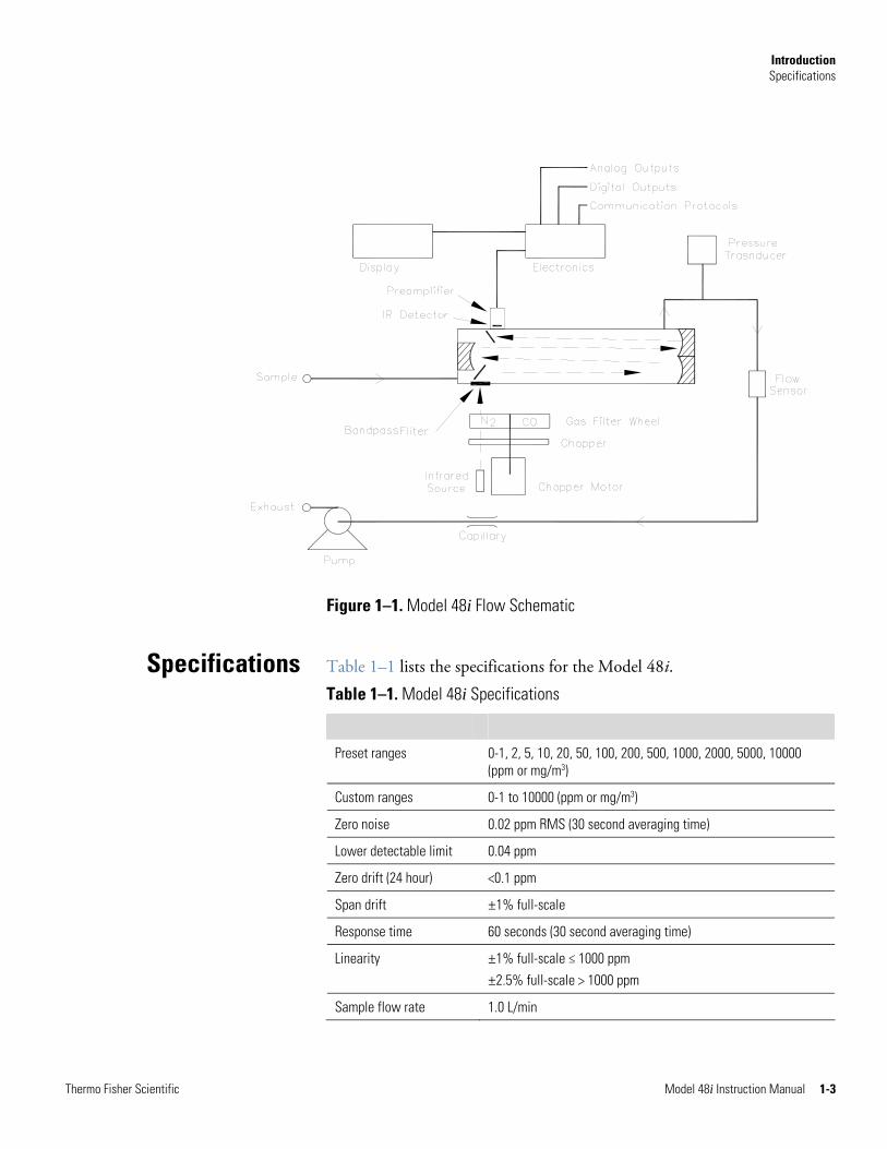
The sample is drawn into the Model 48i through the sample bulkhead, as shown in Figure 1–1. The sample flows through the optical bench. Radiation from an infrared source is chopped and then passed through a gas filter alternating between CO and N2. The radiation then passes through a narrow bandpass interference filter and enters the optical bench where absorption by the sample gas occurs. The infrared radiation then exits the optical bench and falls on an infrared detector.
The CO gas filter acts to produce a reference beam, which cannot be further attenuated by CO in the sample cell. The N2 side of the filter wheel is transparent to the infrared radiation and therefore produces a measurement beam, which can be absorbed by CO in the cell. The chopped detector signal is modulated by the alternation between the two gas filters with an amplitude related to the concentration of CO in the sample cell. Other gases do not cause modulation of the detector signal since they absorb the reference and measure beams equally. Thus, the GFC system responds specifically to CO.
The Model 48i outputs the CO concentration to the front panel display, the analog outputs, and also makes the data available over the serial or Ethernet connection.
Principle of Operation
Introduction Specifications
Thermo Fisher Scientific Model 48i Instruction Manual 1-3
Figure 1–1. Model 48i Flow Schematic
Table 1–1 lists the specifications for the Model 48i.
Table 1–1. Model 48i Specifications
Preset ranges 0-1, 2, 5, 10, 20, 50, 100, 200, 500, 1000, 2000, 5000, 10000 (ppm or mg/m3)
Custom ranges 0-1 to 10000 (ppm or mg/m3)
Zero noise 0.02 ppm RMS (30 second averaging time)
Lower detectable limit 0.04 ppm
Zero drift (24 hour) <0.1 ppm
Span drift ±1% full-scale
Response time 60 seconds (30 second averaging time)
Linearity ±1% full-scale ≤ 1000 ppm ±2.5% full-scale > 1000 ppm
Sample flow rate 1.0 L/min
Specifications
Introduction Specifications
1-4 Model 48i Instruction Manual Thermo Fisher Scientific
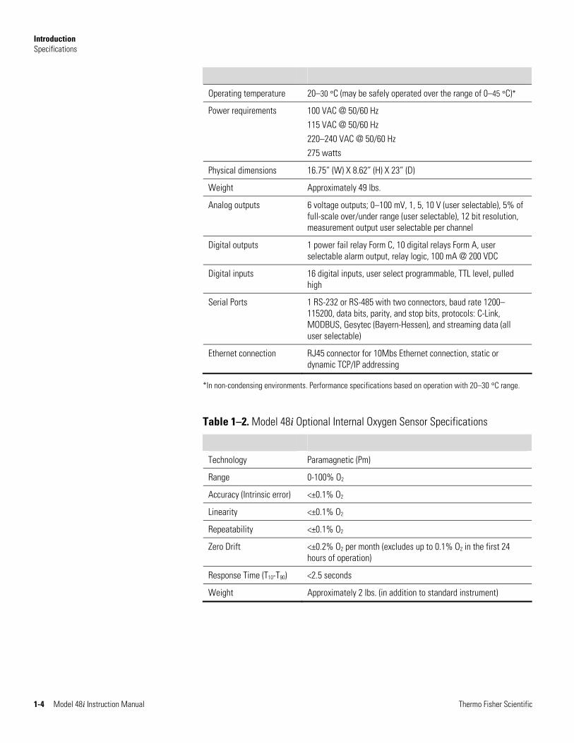
Operating temperature 20–30 °C (may be safely operated over the range of 0–45 °C)*
Power requirements
100 VAC @ 50/60 Hz 115 VAC @ 50/60 Hz 220–240 VAC @ 50/60 Hz 275 watts
Physical dimensions 16.75” (W) X 8.62” (H) X 23” (D)
Weight Approximately 49 lbs.
Analog outputs 6 voltage outputs; 0–100 mV, 1, 5, 10 V (user selectable), 5% of full-scale over/under range (user selectable), 12 bit resolution, measurement output user selectable per channel
Digital outputs 1 power fail relay Form C, 10 digital relays Form A, user selectable alarm output, relay logic, 100 mA @ 200 VDC
Digital inputs 16 digital inputs, user select programmable, TTL level, pulled high
Serial Ports 1 RS-232 or RS-485 with two connectors, baud rate 1200–115200, data bits, parity, and stop bits, protocols: C-Link, MODBUS, Gesytec (Bayern-Hessen), and streaming data (all user selectable)
Ethernet connection RJ45 connector for 10Mbs Ethernet connection, static or dynamic TCP/IP addressing
*In non-condensing environments. Performance specifications based on operation with 20–30 °C range.
Table 1–2. Model 48i Optional Internal Oxygen Sensor Specifications
Technology Paramagnetic (Pm)
Range 0-100% O2
Accuracy (Intrinsic error) <±0.1% O2
Linearity <±0.1% O2
Repeatability <±0.1% O2
Zero Drift <±0.2% O2 per month (excludes up to 0.1% O2 in the first 24 hours of operation)
Response Time (T10-T90) <2.5 seconds
Weight Approximately 2 lbs. (in addition to standard instrument)
Thermo Fisher Scientific Model 48i Instruction Manual 2-1
Chapter 2 Installation
Installation of the Model 48i includes lifting the instrument, unpacking and inspection, connecting sample, zero, span, and exhaust lines, and attaching the analog and/or digital outputs to a recording device. The installation should always be followed by instrument calibration as described in the “Calibration” chapter of this manual.
Installing the Model 48i includes the following recommendations and procedures:
● “Lifting” on page 2-1
● “Unpacking and Inspection” on page 2-1
● “Setup Procedure” on page 2-3
● “Connecting External Devices” on page 2-5
● “Startup” on page 2-9
When lifting the instrument, use procedure appropriate to lifting a heavy object, such as bending at the knees while keeping your back straight and upright. Grasp the instrument at the bottom in the front and at the rear of the unit. Although one person can lift the unit, it is desirable to have two persons lifting, one by grasping the bottom in the front and the other by grasping the bottom in the rear.
Equipment Damage Do not attempt to lift the instrument by the cover or other external fittings. ▲
The Model 48i is shipped complete in one container. If there is obvious damage to the shipping container when you receive the instrument, notify the carrier immediately and hold for inspection. The carrier is responsible for any damage incurred during shipment.
Use the following procedure to unpack and inspect the instrument.
1. Remove the instrument from the shipping container and set it on a table or bench that allows easy access to both the front and rear.
Lifting
Unpacking and Inspection
Installation Unpacking and Inspection
2-2 Model 48i Instruction Manual Thermo Fisher Scientific
Remove Packing (2 pieces)
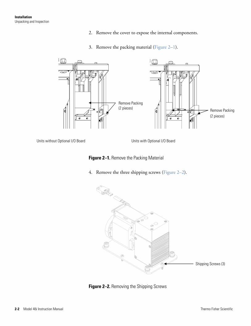
2. Remove the cover to expose the internal components.
3. Remove the packing material (Figure 2–1).
Figure 2–1. Remove the Packing Material
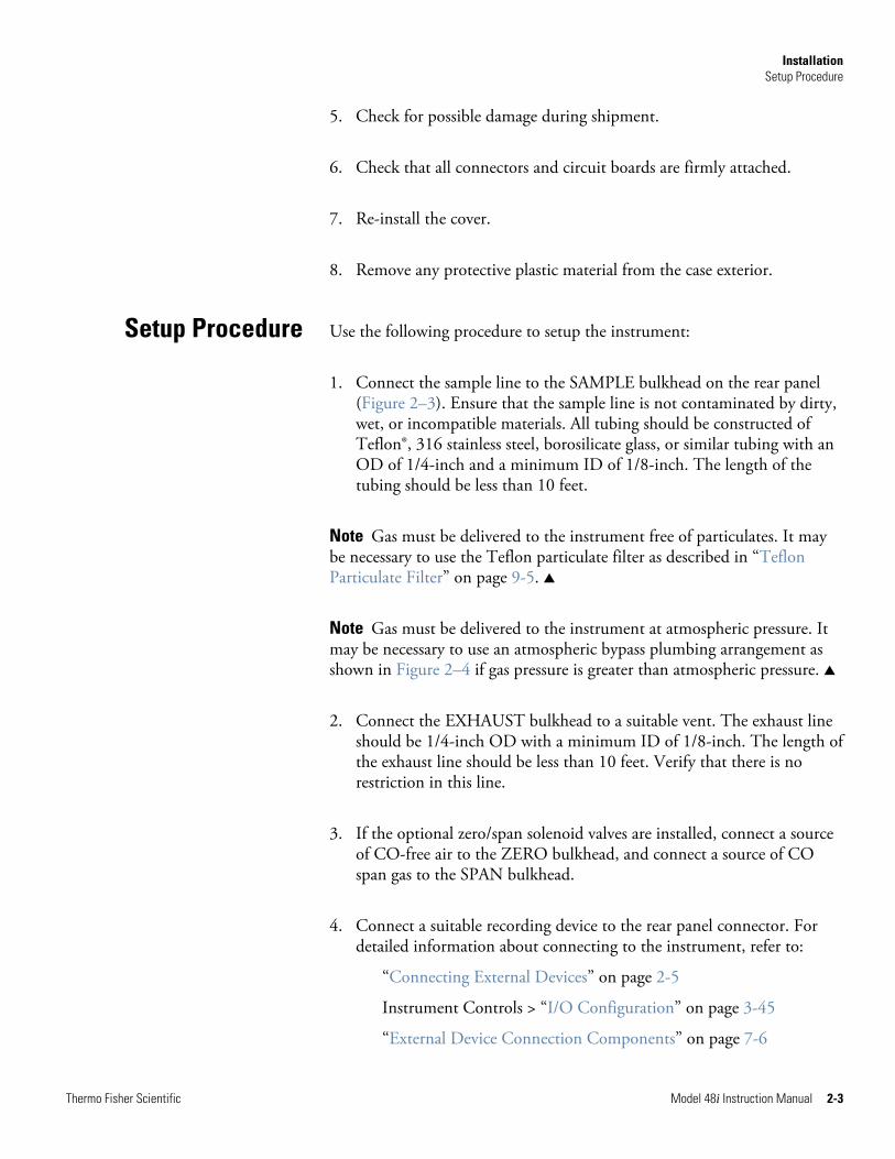
4. Remove the three shipping screws (Figure 2–2).
Figure 2–2. Removing the Shipping Screws
Remove Packing(2 pieces)
Units without Optional I/O Board Units with Optional I/O Board
Shipping Screws (3)
Installation Setup Procedure
Thermo Fisher Scientific Model 48i Instruction Manual 2-3
5. Check for possible damage during shipment.
6. Check that all connectors and circuit boards are firmly attached.
7. Re-install the cover.
8. Remove any protective plastic material from the case exterior.
Use the following procedure to setup the instrument:
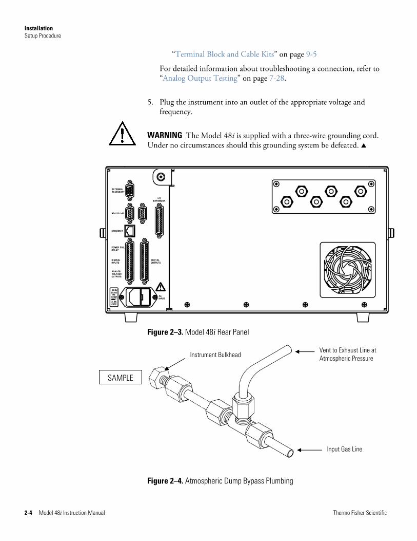
1. Connect the sample line to the SAMPLE bulkhead on the rear panel (Figure 2–3). Ensure that the sample line is not contaminated by dirty, wet, or incompatible materials. All tubing should be constructed of Teflon®, 316 stainless steel, borosilicate glass, or similar tubing with an OD of 1/4-inch and a minimum ID of 1/8-inch. The length of the tubing should be less than 10 feet.
Note Gas must be delivered to the instrument free of particulates. It may be necessary to use the Teflon particulate filter as described in “Teflon Particulate Filter” on page 9-5. ▲
Note Gas must be delivered to the instrument at atmospheric pressure. It may be necessary to use an atmospheric bypass plumbing arrangement as shown in Figure 2–4 if gas pressure is greater than atmospheric pressure. ▲
2. Connect the EXHAUST bulkhead to a suitable vent. The exhaust line should be 1/4-inch OD with a minimum ID of 1/8-inch. The length of the exhaust line should be less than 10 feet. Verify that there is no restriction in this line.
3. If the optional zero/span solenoid valves are installed, connect a source of CO-free air to the ZERO bulkhead, and connect a source of CO span gas to the SPAN bulkhead.
4. Connect a suitable recording device to the rear panel connector. For detailed information about connecting to the instrument, refer to:
“Connecting External Devices” on page 2-5
Instrument Controls > “I/O Configuration” on page 3-45
“External Device Connection Components” on page 7-6
Setup Procedure
Installation Setup Procedure
2-4 Model 48i Instruction Manual Thermo Fisher Scientific
“Terminal Block and Cable Kits” on page 9-5
For detailed information about troubleshooting a connection, refer to “Analog Output Testing” on page 7-28.
5. Plug the instrument into an outlet of the appropriate voltage and frequency.
WARNING The Model 48i is supplied with a three-wire grounding cord. Under no circumstances should this grounding system be defeated. ▲
Figure 2–3. Model 48i Rear Panel
Figure 2–4. Atmospheric Dump Bypass Plumbing
SAMPLE
Input Gas Line
Vent to Exhaust Line at Atmospheric Pressure Instrument Bulkhead
Installation Connecting External Devices
Thermo Fisher Scientific Model 48i Instruction Manual 2-5
Several components are available for connecting external devices to iSeries instruments.
These connection options include:
● Individual terminal board PCB assemblies
● Terminal block and cable kits (optional)
● Individual cables (optional)
For detailed information on the optional connection components, refer to the “Optional Equipment” chapter. For associated part numbers, refer to “External Device Connection Components” on page 7-6.
The terminal board PCB assemblies are circuit boards with a D-Sub connector on one side and a series of screw terminals on the other side. This assembly provide a convenient mechanism for connecting wires from a data system to the analyzer’s I/O connectors.
The following terminal board PCB assemblies are available for iSeries instruments:
● I/O terminal board PCB assembly, 37 pin (standard)
● D/O terminal board PCB assembly, 37 pin (standard)
● 25-pin terminal board PCB assembly, (included with optional I/O Expansion Board)
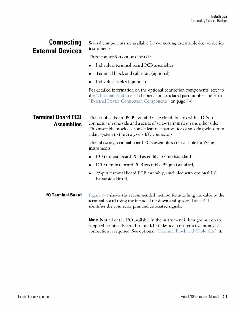
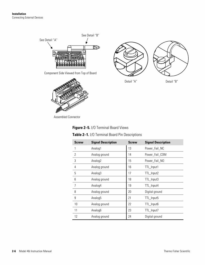
Figure 2–5 shows the recommended method for attaching the cable to the terminal board using the included tie-down and spacer. Table 2–1 identifies the connector pins and associated signals.
Note Not all of the I/O available in the instrument is brought out on the supplied terminal board. If more I/O is desired, an alternative means of connection is required. See optional “Terminal Block and Cable Kits”. ▲
Connecting External Devices
Terminal Board PCB Assemblies
I/O Terminal Board
Installation Connecting External Devices
2-6 Model 48i Instruction Manual Thermo Fisher Scientific
Figure 2–5. I/O Terminal Board Views
Table 2–1. I/O Terminal Board Pin Descriptions
Screw Signal Description Screw Signal Description
1 Analog1 13 Power_Fail_NC
2 Analog ground 14 Power_Fail_COM
3 Analog2 15 Power_Fail_NO
4 Analog ground 16 TTL_Input1
5 Analog3 17 TTL_Input2
6 Analog ground 18 TTL_Input3
7 Analog4 19 TTL_Input4
8 Analog ground 20 Digital ground
9 Analog5 21 TTL_Input5
10 Analog ground 22 TTL_Input6
11 Analog6 23 TTL_Input7
12 Analog ground 24 Digital ground
Component Side Viewed from Top of Board
Detail “A” Detail “B”
Assembled Connector
See Detail “A” See Detail “B”
Installation Connecting External Devices
Thermo Fisher Scientific Model 48i Instruction Manual 2-7
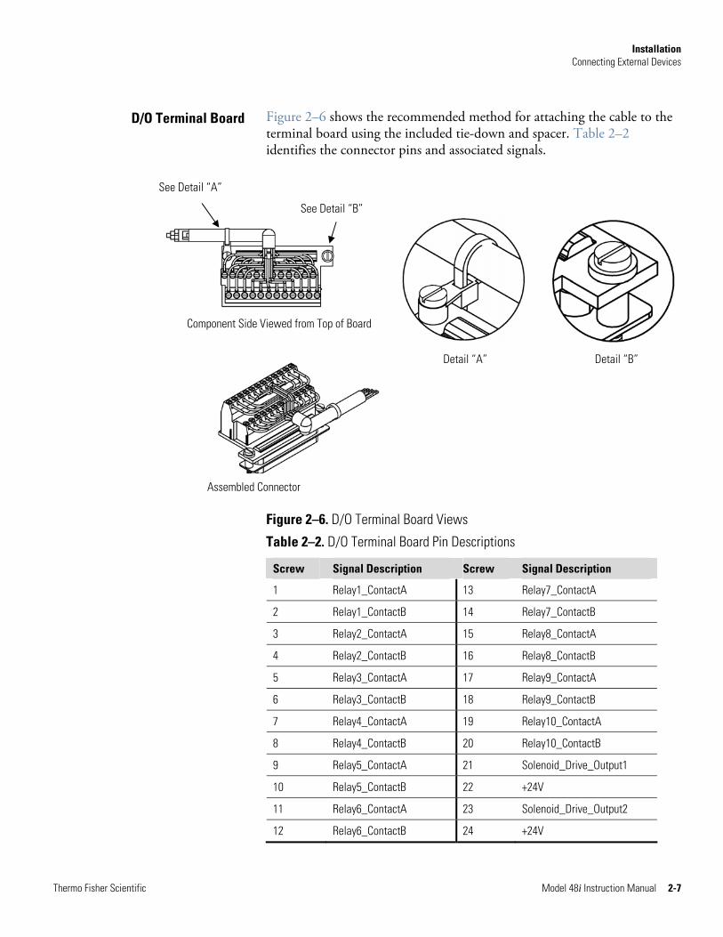
Figure 2–6 shows the recommended method for attaching the cable to the terminal board using the included tie-down and spacer. Table 2–2 identifies the connector pins and associated signals.
Figure 2–6. D/O Terminal Board Views
Table 2–2. D/O Terminal Board Pin Descriptions
Screw Signal Description Screw Signal Description
1 Relay1_ContactA 13 Relay7_ContactA
2 Relay1_ContactB 14 Relay7_ContactB
3 Relay2_ContactA 15 Relay8_ContactA
4 Relay2_ContactB 16 Relay8_ContactB
5 Relay3_ContactA 17 Relay9_ContactA
6 Relay3_ContactB 18 Relay9_ContactB
7 Relay4_ContactA 19 Relay10_ContactA
8 Relay4_ContactB 20 Relay10_ContactB
9 Relay5_ContactA 21 Solenoid_Drive_Output1
10 Relay5_ContactB 22 +24V
11 Relay6_ContactA 23 Solenoid_Drive_Output2
12 Relay6_ContactB 24 +24V
D/O Terminal Board
Component Side Viewed from Top of Board
Detail “A” Detail “B”
Assembled Connector
See Detail “A”
See Detail “B”
Installation Connecting External Devices
2-8 Model 48i Instruction Manual Thermo Fisher Scientific
Assembled Connector
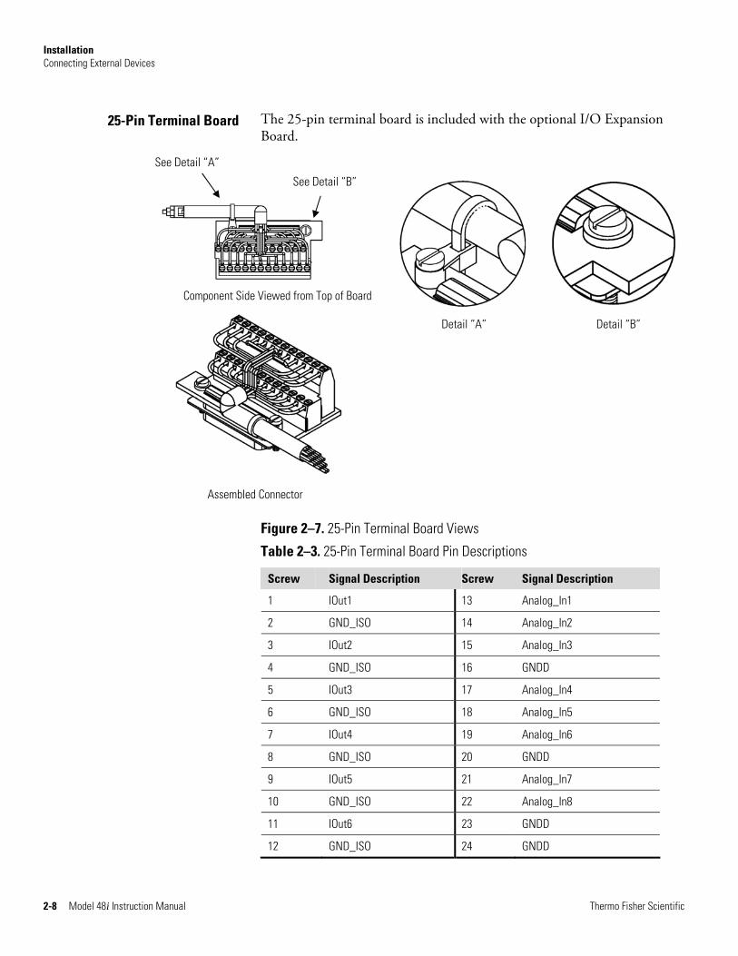
The 25-pin terminal board is included with the optional I/O Expansion Board.
Figure 2–7. 25-Pin Terminal Board Views
Table 2–3. 25-Pin Terminal Board Pin Descriptions
Screw Signal Description Screw Signal Description
1 IOut1 13 Analog_In1
2 GND_ISO 14 Analog_In2
3 IOut2 15 Analog_In3
4 GND_ISO 16 GNDD
5 IOut3 17 Analog_In4
6 GND_ISO 18 Analog_In5
7 IOut4 19 Analog_In6
8 GND_ISO 20 GNDD
9 IOut5 21 Analog_In7
10 GND_ISO 22 Analog_In8
11 IOut6 23 GNDD
12 GND_ISO 24 GNDD
25-Pin Terminal Board
Component Side Viewed from Top of Board
Detail “A” Detail “B”
See Detail “A”
See Detail “B”
Installation Startup
Thermo Fisher Scientific Model 48i Instruction Manual 2-9
Use the following procedure when starting the instrument.
1. Turn the power ON.
2. Allow 90 minutes for the instrument to stabilize.
3. Set instrument parameters such as operating ranges and averaging times to appropriate settings. For more information about instrument parameters, see the “Operation” chapter.
4. Before beginning the actual monitoring, perform a multipoint calibration as described in the “Calibration” chapter.
Startup

Thermo Fisher Scientific Model 48i Instruction Manual 3-1
Chapter 3 Operation
This chapter describes the front panel display, front panel pushbuttons, and menu-driven firmware. For details, see the following topics:
● “Display” on page 3-1
● “Pushbuttons” on page 3-2
● “Firmware Overview” on page 3-4
● “Range Menu” on page 3-8
● “Averaging Time” on page 3-16
● “Calibration Factors Menu” on page 3-16
● “Calibration Menu” on page 3-20
● “Instrument Controls Menu” on page 3-25
● “Diagnostics Menu” on page 3-61
● “Alarms Menu” on page 3-68
● “Service Menu” on page 3-78
● “Password” on page 3-94
The 320 x 240 graphics liquid-crystal display (LCD) shows the sample concentrations, instrument parameters, instrument controls, help, and error messages. Some menus contain more items than can be displayed at one time. For these menus, use and to move the cursor up and down to each item.
Display
Operation Pushbuttons
3-2 Model 48i Instruction Manual Thermo Fisher Scientific
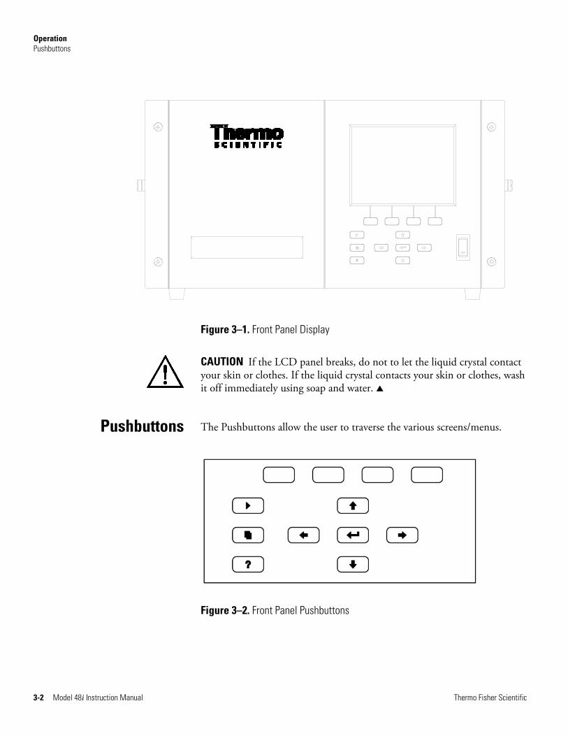
Figure 3–1. Front Panel Display
CAUTION If the LCD panel breaks, do not to let the liquid crystal contact your skin or clothes. If the liquid crystal contacts your skin or clothes, wash it off immediately using soap and water. ▲
The Pushbuttons allow the user to traverse the various screens/menus.
Figure 3–2. Front Panel Pushbuttons
Pushbuttons
Operation Pushbuttons
Thermo Fisher Scientific Model 48i Instruction Manual 3-3
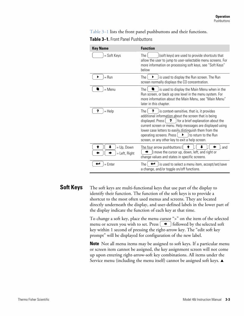
Table 3–1 lists the front panel pushbuttons and their functions.
Table 3–1. Front Panel Pushbuttons
Key Name Function
= Soft Keys The (soft keys) are used to provide shortcuts that allow the user to jump to user-selectable menu screens. For more information on processing soft keys, see “Soft Keys” below
= Run The is used to display the Run screen. The Run screen normally displays the CO concentration.
= Menu The is used to display the Main Menu when in the Run screen, or back up one level in the menu system. For more information about the Main Menu, see “Main Menu” later in this chapter.
= Help The is context-sensitive, that is, it provides additional information about the screen that is being displayed. Press for a brief explanation about the current screen or menu. Help messages are displayed using lower case letters to easily distinguish them from the operating screens. Press to return to the Run screen, or any other key to exit a help screen.
= Up, Down
= Left, Right The four arrow pushbuttons ( , , , and
) move the cursor up, down, left, and right or change values and states in specific screens.
= Enter The is used to select a menu item, accept/set/save a change, and/or toggle on/off functions.
The soft keys are multi-functional keys that use part of the display to identify their function. The function of the soft keys is to provide a shortcut to the most often used menus and screens. They are located directly underneath the display, and user-defined labels in the lower part of the display indicate the function of each key at that time.
To change a soft key, place the menu cursor “>” on the item of the selected menu or screen you wish to set. Press followed by the selected soft key within 1 second of pressing the right-arrow key. The “edit soft key prompt” will be displayed for configuration of the new label.
Note Not all menu items may be assigned to soft keys. If a particular menu or screen item cannot be assigned, the key assignment screen will not come up upon entering right-arrow-soft key combinations. All items under the Service menu (including the menu itself) cannot be assigned soft keys. ▲
Soft Keys
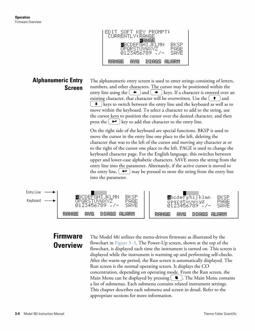
Operation Firmware Overview
3-4 Model 48i Instruction Manual Thermo Fisher Scientific
ANGE abcdefghijklmn BKSP opqrstuvwxyz PAGE 0123456789 ./- SAVE RANGE AVG DIAGS ALARM
EDIT SOFT KEY PROMPT: CURRENTLY:RANGE RANGE ABCDEFGHIJKLMN BKSP OPQRSTUVWXYZ PAGE 0123456789 ./- SAVE RANGE AVG DIAGS ALARM
The alphanumeric entry screen is used to enter strings consisting of letters, numbers, and other characters. The cursor may be positioned within the entry line using the and keys. If a character is entered over an existing character, that character will be overwritten. Use the and
keys to switch between the entry line and the keyboard as well as to move within the keyboard. To select a character to add to the string, use the cursor keys to position the cursor over the desired character, and then press the key to add that character to the entry line.
On the right side of the keyboard are special functions. BKSP is used to move the cursor in the entry line one place to the left, deleting the character that was to the left of the cursor and moving any character at or to the right of the cursor one place to the left. PAGE is used to change the keyboard character page. For the English language, this switches between upper and lower-case alphabetic characters. SAVE stores the string from the entry line into the parameter. Alternately, if the active cursor is moved to the entry line, may be pressed to store the string from the entry line into the parameter.
The Model 48i utilizes the menu-driven firmware as illustrated by the flowchart in Figure 3–3. The Power-Up screen, shown at the top of the flowchart, is displayed each time the instrument is turned on. This screen is displayed while the instrument is warming up and performing self-checks. After the warm-up period, the Run screen is automatically displayed. The Run screen is the normal operating screen. It displays the CO concentration, depending on operating mode. From the Run screen, the Main Menu can be displayed by pressing . The Main Menu contains a list of submenus. Each submenu contains related instrument settings. This chapter describes each submenu and screen in detail. Refer to the appropriate sections for more information.
Alphanumeric Entry Screen
Firmware Overview
ANGE ABCDEFGHIJKLMN BKSP OPQRSTUVWXYZ PAGE 0123456789 ./- SAVE RANGE AVG DIAGS ALARM
Entry Line
Keyboard
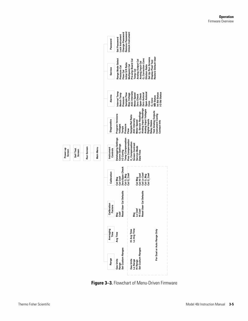
Operation Firmware Overview
Thermo Fisher Scientific Model 48i Instruction Manual 3-5
Gas
Un
its
Ran
ge
Set
Cu
sto
m R
ang
es
Gas
Un
its
Lo
Ran
ge
Hi R
ang
eS
et C
ust
um
Ran
ges
Ran
ge
Ave
rag
ing
Tim
e
Avg
Tim
e
Hi A
vg T
ime
Lo
Avg
Tim
e
Cal
ibra
tio
nF
acto
rs
Bkg
Co
efR
eset
Use
r C
al D
efau
lts
Bkg
Lo
Co
efH
i Co
efR
eset
Use
r C
al D
efau
lts
Cal
ibra
tio
n
Cal
Bkg
Cal
Co
efZ
ero
/Sp
an C
hec
kC
al O
Bkg
Cal
O C
oef
Cal
Bkg
Cal
Hi C
oef
Cal
Lo
Co
efC
al O
Bkg
Cal
O C
oef
Inst
rum
ent
Co
ntr
ols
Dat
alo
gg
ing
Set
tin
gs
Co
mm
Set
tin
gs
I/O C
on
fig
Tem
p C
om
pen
sati
on
Pre
s C
om
pen
sati
on
O C
om
pen
sati
on
Scr
een
Co
ntr
ast
Ser
vice
Mo
de
Dat
e/T
ime
Dia
gn
ost
ics
Pro
gra
m V
ersi
on
sV
olt
ages
Tem
ps
Pre
ssu
reF
low
Sam
ple
/Ref
Rat
ioA
GC
Inte
nsi
tyM
oto
r S
pee
dO
Sen
sor
Rea
din
gs
An
alo
g In
pu
t R
ead
ing
sA
nal
og
Inp
ut
Vo
ltag
esD
igit
al In
pu
tsR
elay
Sta
tes
Tes
t A
nal
og
Ou
tpu
tsIn
stru
men
t C
on
fig
Co
nta
ct In
fo
Ala
rms
Inte
rnal
Tem
pB
ench
Tem
pP
ress
ure
Sam
ple
Flo
wB
ias
Vo
ltag
eA
GC
Inte
nsi
tyM
oto
r S
pee
dZ
ero
Ch
eck
Sp
an C
hec
kZ
ero
Au
toca
lS
pan
Au
toca
lC
on
cO
Co
nc
MB
Sta
tus
Int
Bd
Sta
tus
I/O B
d S
tatu
s
Ser
vice
Ran
ge
Mo
de
Sel
ect
Pre
ssu
re C
alF
low
Cal
Init
ial S
/R R
atio
Mu
ltip
oin
t C
alP
re−a
mp
Bo
ard
Cal
Tem
p C
alA
nal
og
Ou
tpu
t C
alA
nal
og
Inp
ut
Cal
O C
orr
ecti
on
Co
nc
Dilu
tio
n R
atio
Set
Up
Ru
n S
cree
ns
Dis
pla
y P
ixel
Tes
tR
esto
re D
efau
lt U
ser
Pas
swo
rd
Set
Pas
swo
rdL
ock
Inst
rum
ent
Ch
ang
e P
assw
ord
Rem
ove
Pas
swo
rdU
nlo
ck In
stru
men
t
Mai
n M
enu
Ru
n S
cree
n
Po
wer
−up
Scr
een
Fo
r D
ual
or
Au
to R
ang
e O
nly
Sel
f T
est
Scr
een
2 2 2 2
2
2
2
2
Figure 3–3. Flowchart of Menu-Driven Firmware

Operation Firmware Overview
3-6 Model 48i Instruction Manual Thermo Fisher Scientific
The Power-Up screen is displayed on power up of the Model 48i. This screen is displayed while the internal components are warming up and diagnostic checks are performed.
Please wait while booting...
The Run screen displays the current CO concentrations. The status bar displays the time (24-hour format), the password (lock) icon, service (wrench) icon, alarm (bell) icon, and optional zero/span sample solenoid valve status, if installed.
The word “SAMPLE” on the left of the status bar indicates the analyzer has the zero/span valve option and is in “SAMPLE” mode. Other modes appear in the same area of the display as “ZERO” or “SPAN”. For more information about the optional solenoid valves, see Chapter 9, “Optional Equipment”.
Power-Up Screen
Run Screen
The password (lock) icon indicates that no parameter changes can be made from the front panel.
The alarm (bell) icon indicates that an alarm is active.
The service (wrench) icon indicates that the instrument is in the service mode.
Status Bar Icons
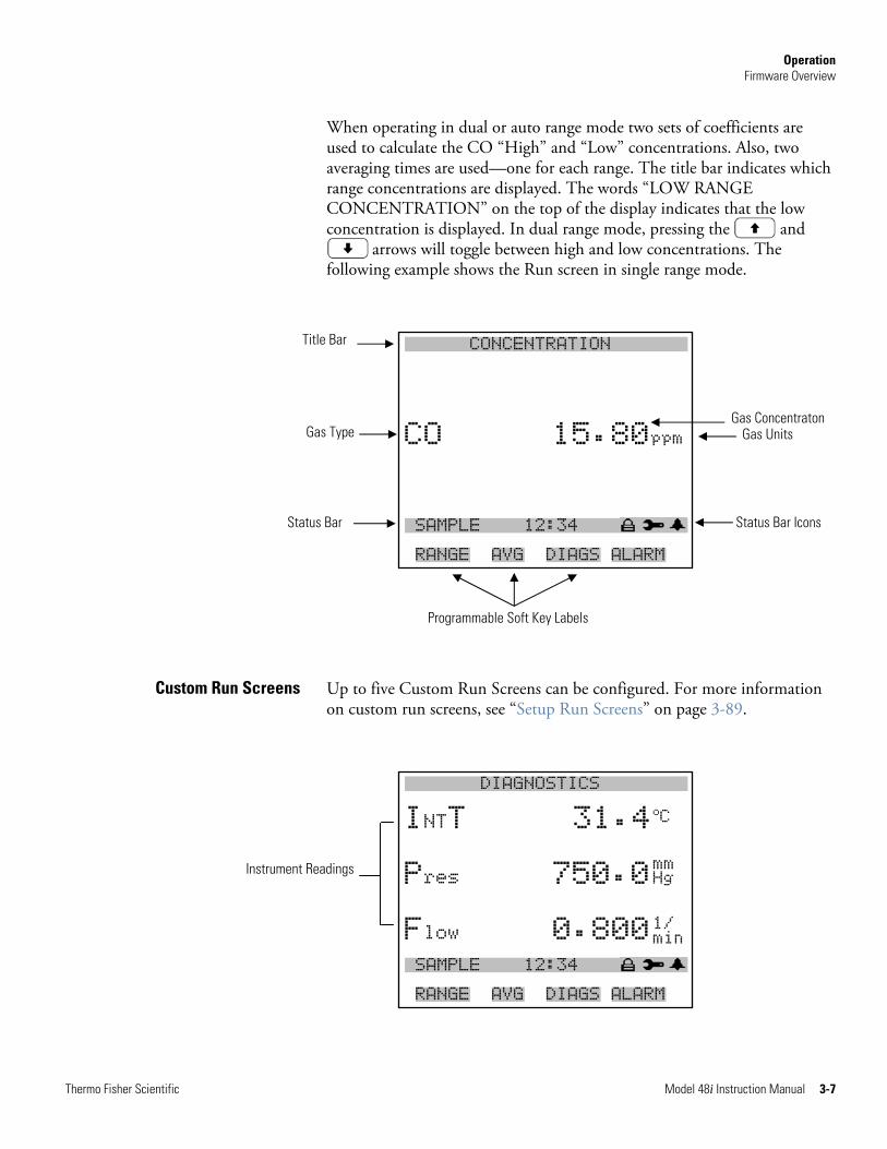
Operation Firmware Overview
Thermo Fisher Scientific Model 48i Instruction Manual 3-7
Instrument Readings
When operating in dual or auto range mode two sets of coefficients are used to calculate the CO “High” and “Low” concentrations. Also, two averaging times are used—one for each range. The title bar indicates which range concentrations are displayed. The words “LOW RANGE CONCENTRATION” on the top of the display indicates that the low concentration is displayed. In dual range mode, pressing the and
arrows will toggle between high and low concentrations. The following example shows the Run screen in single range mode.
X CONCENTRATION W
NO 28.7 PPB
CO 15.80ppm
NOx 29.2 PPB SAMPLE 12:34 ALARMx RANGE AVG DIAGS ALARM
Up to five Custom Run Screens can be configured. For more information on custom run screens, see “Setup Run Screens” on page 3-89.
X DIAGNOSTICS W
INTT 31.4
Pres 750.0
Flow 0.800 SAMPLE 12:34 ALARMx RANGE AVG DIAGS ALARM
Custom Run Screens
Programmable Soft Key Labels
Title Bar
Gas Type
Status Bar
Gas Concentraton Gas Units
Status Bar Icons
oC mm Hg 1/ min
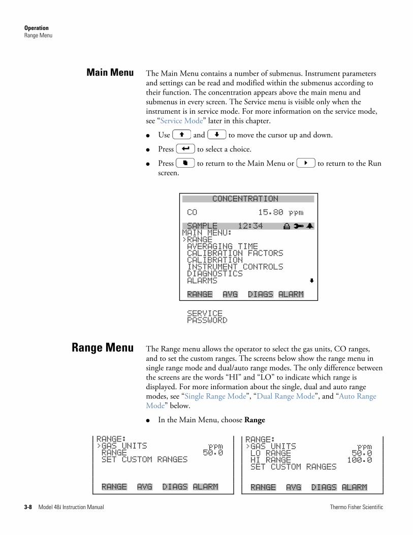
Operation Range Menu
3-8 Model 48i Instruction Manual Thermo Fisher Scientific
The Main Menu contains a number of submenus. Instrument parameters and settings can be read and modified within the submenus according to their function. The concentration appears above the main menu and submenus in every screen. The Service menu is visible only when the instrument is in service mode. For more information on the service mode, see “Service Mode” later in this chapter.
● Use and to move the cursor up and down.
● Press to select a choice.
● Press to return to the Main Menu or to return to the Run screen.
XXLO WCONCENTRATIONXXLO W CO 15.80 ppm xSAMPLE 12:34 ALARMx MAIN MENU: >RANGE AVERAGING TIME CALIBRATION FACTORS CALIBRATION INSTRUMENT CONTROLS DIAGNOSTICS ALARMS RANGE AVG DIAGS ALARM
SERVICE PASSWORD
The Range menu allows the operator to select the gas units, CO ranges, and to set the custom ranges. The screens below show the range menu in single range mode and dual/auto range modes. The only difference between the screens are the words “HI” and “LO” to indicate which range is displayed. For more information about the single, dual and auto range modes, see “Single Range Mode”, “Dual Range Mode”, and “Auto Range Mode” below.
● In the Main Menu, choose Range
Main Menu
Range Menu
RANGE: >GAS UNITS ppm RANGE 50.0 SET CUSTOM RANGES RANGE AVG DIAGS ALARM
RANGE: >GAS UNITS ppm LO RANGE 50.0 HI RANGE 100.0 SET CUSTOM RANGES RANGE AVG DIAGS ALARM
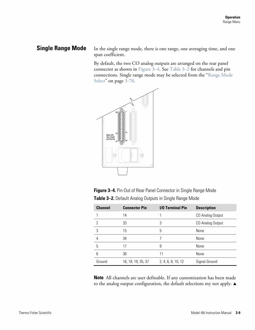
Operation Range Menu
Thermo Fisher Scientific Model 48i Instruction Manual 3-9
In the single range mode, there is one range, one averaging time, and one span coefficient.
By default, the two CO analog outputs are arranged on the rear panel connector as shown in Figure 3–4. See Table 3–2 for channels and pin connections. Single range mode may be selected from the “Range Mode Select” on page 3-78.
Figure 3–4. Pin-Out of Rear Panel Connector in Single Range Mode
Table 3–2. Default Analog Outputs in Single Range Mode
Channel Connector Pin I/O Terminal Pin Description
1 14 1 CO Analog Output
2 33 3 CO Analog Output
3 15 5 None
4 34 7 None
5 17 9 None
6 36 11 None
Ground 16, 18, 19, 35, 37 2, 4, 6, 8, 10, 12 Signal Ground
Note All channels are user definable. If any customization has been made to the analog output configuration, the default selections my not apply. ▲
Single Range Mode
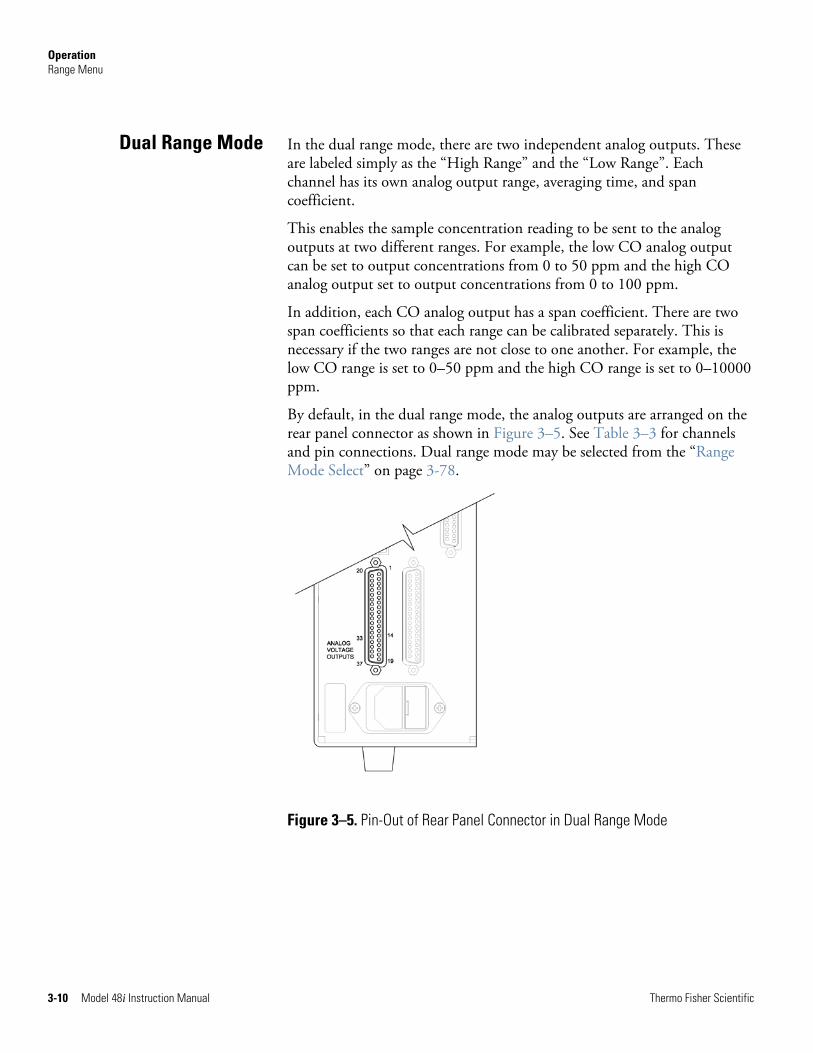
Operation Range Menu
3-10 Model 48i Instruction Manual Thermo Fisher Scientific
In the dual range mode, there are two independent analog outputs. These are labeled simply as the “High Range” and the “Low Range”. Each channel has its own analog output range, averaging time, and span coefficient.
This enables the sample concentration reading to be sent to the analog outputs at two different ranges. For example, the low CO analog output can be set to output concentrations from 0 to 50 ppm and the high CO analog output set to output concentrations from 0 to 100 ppm.
In addition, each CO analog output has a span coefficient. There are two span coefficients so that each range can be calibrated separately. This is necessary if the two ranges are not close to one another. For example, the low CO range is set to 0–50 ppm and the high CO range is set to 0–10000 ppm.
By default, in the dual range mode, the analog outputs are arranged on the rear panel connector as shown in Figure 3–5. See Table 3–3 for channels and pin connections. Dual range mode may be selected from the “Range Mode Select” on page 3-78.
Figure 3–5. Pin-Out of Rear Panel Connector in Dual Range Mode
Dual Range Mode
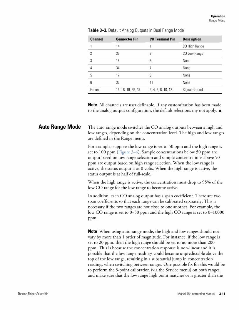
Operation Range Menu
Thermo Fisher Scientific Model 48i Instruction Manual 3-11
Table 3–3. Default Analog Outputs in Dual Range Mode
Channel Connector Pin I/O Terminal Pin Description
1 14 1 CO High Range
2 33 3 CO Low Range
3 15 5 None
4 34 7 None
5 17 9 None
6 36 11 None
Ground 16, 18, 19, 35, 37 2, 4, 6, 8, 10, 12 Signal Ground
Note All channels are user definable. If any customization has been made to the analog output configuration, the default selections my not apply. ▲
The auto range mode switches the CO analog outputs between a high and low ranges, depending on the concentration level. The high and low ranges are defined in the Range menu.
For example, suppose the low range is set to 50 ppm and the high range is set to 100 ppm (Figure 3–6). Sample concentrations below 50 ppm are output based on low range selection and sample concentrations above 50 ppm are output based on high range selection. When the low range is active, the status output is at 0 volts. When the high range is active, the status output is at half of full-scale.
When the high range is active, the concentration must drop to 95% of the low CO range for the low range to become active.
In addition, each CO analog output has a span coefficient. There are two span coefficients so that each range can be calibrated separately. This is necessary if the two ranges are not close to one another. For example, the low CO range is set to 0–50 ppm and the high CO range is set to 0–10000 ppm.
Note When using auto range mode, the high and low ranges should not vary by more than 1 order of magnitude. For instance, if the low range is set to 20 ppm, then the high range should be set to no more than 200 ppm. This is because the concentration response is non-linear and it is possible that the low range readings could become unpredictable above the top of the low range, resulting in a substantial jump in concentration readings when switching between ranges. One possible fix for this would be to perform the 3-point calibration (via the Service menu) on both ranges and make sure that the low range high point matches or is greater than the
Auto Range Mode
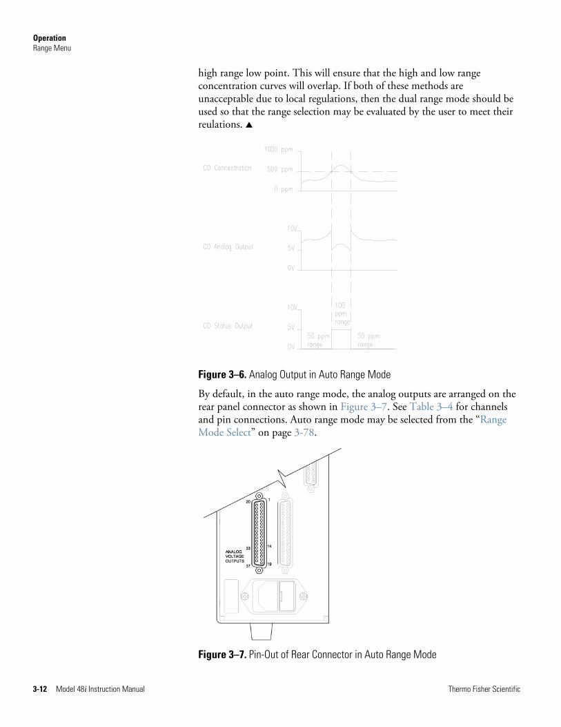
Operation Range Menu
3-12 Model 48i Instruction Manual Thermo Fisher Scientific
high range low point. This will ensure that the high and low range concentration curves will overlap. If both of these methods are unacceptable due to local regulations, then the dual range mode should be used so that the range selection may be evaluated by the user to meet their reulations. ▲
Figure 3–6. Analog Output in Auto Range Mode
By default, in the auto range mode, the analog outputs are arranged on the rear panel connector as shown in Figure 3–7. See Table 3–4 for channels and pin connections. Auto range mode may be selected from the “Range Mode Select” on page 3-78.
Figure 3–7. Pin-Out of Rear Connector in Auto Range Mode
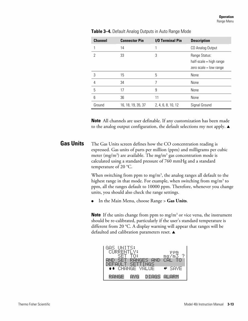
Operation Range Menu
Thermo Fisher Scientific Model 48i Instruction Manual 3-13
Table 3–4. Default Analog Outputs in Auto Range Mode
Channel Connector Pin I/O Terminal Pin Description
1 14 1 CO Analog Output
2 33 3 Range Status: half-scale = high range zero scale = low range
3 15 5 None
4 34 7 None
5 17 9 None
6 36 11 None
Ground 16, 18, 19, 35, 37 2, 4, 6, 8, 10, 12 Signal Ground
Note All channels are user definable. If any customization has been made to the analog output configuration, the default selections my not apply. ▲
The Gas Units screen defines how the CO concentration reading is expressed. Gas units of parts per million (ppm) and milligrams per cubic meter (mg/m3) are available. The mg/m3 gas concentration mode is calculated using a standard pressure of 760 mmHg and a standard temperature of 20 °C.
When switching from ppm to mg/m3, the analog ranges all default to the highest range in that mode. For example, when switching from mg/m3 to ppm, all the ranges default to 10000 ppm. Therefore, whenever you change units, you should also check the range settings.
● In the Main Menu, choose Range > Gas Units.
Note If the units change from ppm to mg/m3 or vice versa, the instrument should be re-calibrated, particularly if the user’s standard temperature is different from 20 °C. A display warning will appear that ranges will be defaulted and calibration parameters reset. ▲
GAS UNITS: CURRENTLY: ppm SET TO: mg/m3 ? AND SET RANGES AND CAL TOX DEFAULT SETTINGSXXXXXXXXXX CHANGE VALUE SAVE RANGE AVG DIAGS ALARM
Gas Units
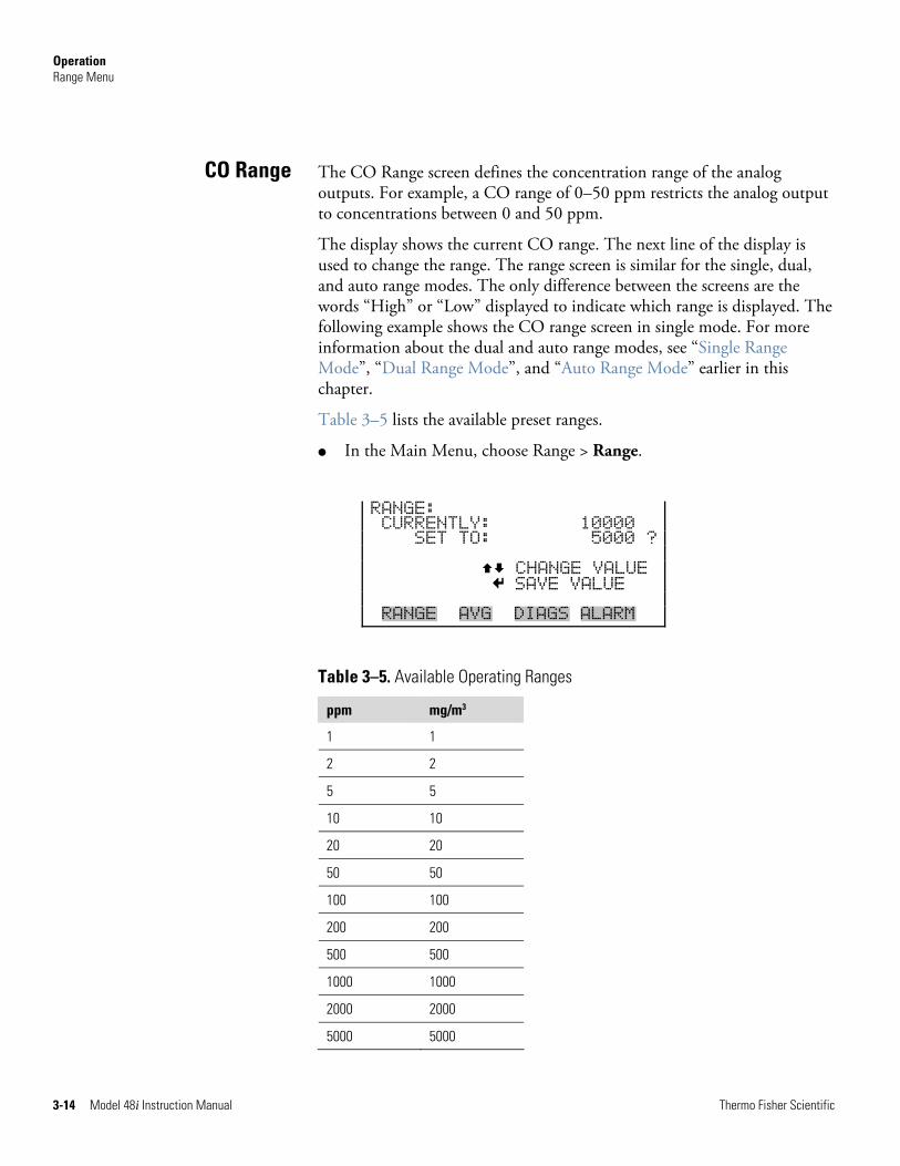
Operation Range Menu
3-14 Model 48i Instruction Manual Thermo Fisher Scientific
The CO Range screen defines the concentration range of the analog outputs. For example, a CO range of 0–50 ppm restricts the analog output to concentrations between 0 and 50 ppm.
The display shows the current CO range. The next line of the display is used to change the range. The range screen is similar for the single, dual, and auto range modes. The only difference between the screens are the words “High” or “Low” displayed to indicate which range is displayed. The following example shows the CO range screen in single mode. For more information about the dual and auto range modes, see “Single Range Mode”, “Dual Range Mode”, and “Auto Range Mode” earlier in this chapter.
Table 3–5 lists the available preset ranges.
● In the Main Menu, choose Range > Range.
RANGE: CURRENTLY: 10000 SET TO: 5000 ? CHANGE VALUE SAVE VALUE RANGE AVG DIAGS ALARM
Table 3–5. Available Operating Ranges
ppm mg/m3
1 1
2 2
5 5
10 10
20 20
50 50
100 100
200 200
500 500
1000 1000
2000 2000
5000 5000
CO Range
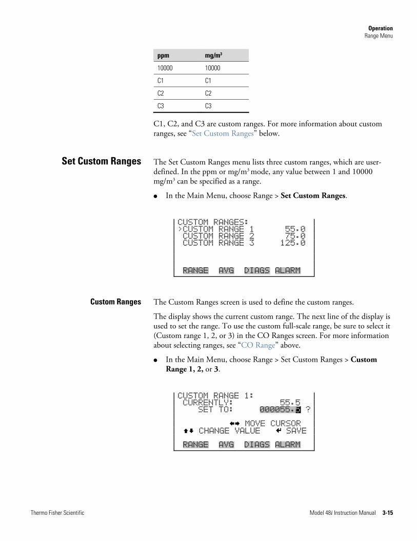
Operation Range Menu
Thermo Fisher Scientific Model 48i Instruction Manual 3-15
ppm mg/m3
10000 10000
C1 C1
C2 C2
C3 C3
C1, C2, and C3 are custom ranges. For more information about custom ranges, see “Set Custom Ranges” below.
The Set Custom Ranges menu lists three custom ranges, which are user-defined. In the ppm or mg/m3 mode, any value between 1 and 10000 mg/m3 can be specified as a range.
● In the Main Menu, choose Range > Set Custom Ranges.
CUSTOM RANGES: >CUSTOM RANGE 1 55.0 CUSTOM RANGE 2 75.0 CUSTOM RANGE 3 125.0 RANGE AVG DIAGS ALARM
The Custom Ranges screen is used to define the custom ranges.
The display shows the current custom range. The next line of the display is used to set the range. To use the custom full-scale range, be sure to select it (Custom range 1, 2, or 3) in the CO Ranges screen. For more information about selecting ranges, see “CO Range” above.
● In the Main Menu, choose Range > Set Custom Ranges > Custom Range 1, 2, or 3.
CUSTOM RANGE 1: CURRENTLY: 55.5 SET TO: 000055.5 ? MOVE CURSOR CHANGE VALUE SAVE RANGE AVG DIAGS ALARM
Set Custom Ranges
Custom Ranges
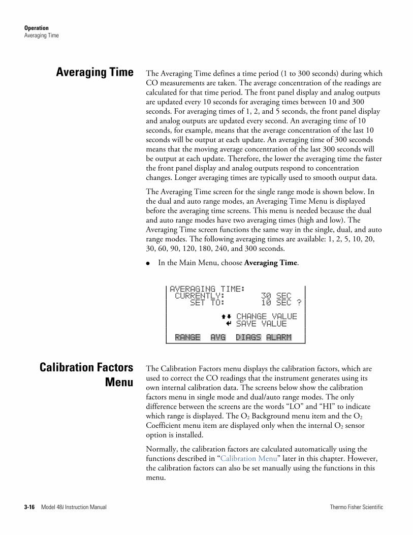
Operation Averaging Time
3-16 Model 48i Instruction Manual Thermo Fisher Scientific
The Averaging Time defines a time period (1 to 300 seconds) during which CO measurements are taken. The average concentration of the readings are calculated for that time period. The front panel display and analog outputs are updated every 10 seconds for averaging times between 10 and 300 seconds. For averaging times of 1, 2, and 5 seconds, the front panel display and analog outputs are updated every second. An averaging time of 10 seconds, for example, means that the average concentration of the last 10 seconds will be output at each update. An averaging time of 300 seconds means that the moving average concentration of the last 300 seconds will be output at each update. Therefore, the lower the averaging time the faster the front panel display and analog outputs respond to concentration changes. Longer averaging times are typically used to smooth output data.
The Averaging Time screen for the single range mode is shown below. In the dual and auto range modes, an Averaging Time Menu is displayed before the averaging time screens. This menu is needed because the dual and auto range modes have two averaging times (high and low). The Averaging Time screen functions the same way in the single, dual, and auto range modes. The following averaging times are available: 1, 2, 5, 10, 20, 30, 60, 90, 120, 180, 240, and 300 seconds.
● In the Main Menu, choose Averaging Time.
AVERAGING TIME: CURRENTLY: 30 SEC SET TO: 10 SEC ? CHANGE VALUE SAVE VALUE RANGE AVG DIAGS ALARM
The Calibration Factors menu displays the calibration factors, which are used to correct the CO readings that the instrument generates using its own internal calibration data. The screens below show the calibration factors menu in single mode and dual/auto range modes. The only difference between the screens are the words “LO” and “HI” to indicate which range is displayed. The O2 Background menu item and the O2 Coefficient menu item are displayed only when the internal O2 sensor option is installed.
Normally, the calibration factors are calculated automatically using the functions described in “Calibration Menu” later in this chapter. However, the calibration factors can also be set manually using the functions in this menu.
Averaging Time
Calibration FactorsMenu
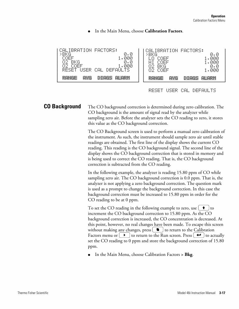
Operation Calibration Factors Menu
Thermo Fisher Scientific Model 48i Instruction Manual 3-17
● In the Main Menu, choose Calibration Factors.
RESET USER CAL DEFAULTS
The CO background correction is determined during zero calibration. The CO background is the amount of signal read by the analyzer while sampling zero air. Before the analyzer sets the CO reading to zero, it stores this value as the CO background correction.
The CO Background screen is used to perform a manual zero calibration of the instrument. As such, the instrument should sample zero air until stable readings are obtained. The first line of the display shows the current CO reading. This reading is the CO background signal. The second line of the display shows the CO background correction that is stored in memory and is being used to correct the CO reading. That is, the CO background correction is subtracted from the CO reading.
In the following example, the analyzer is reading 15.80 ppm of CO while sampling zero air. The CO background correction is 0.0 ppm. That is, the analyzer is not applying a zero background correction. The question mark is used as a prompt to change the background correction. In this case the background correction must be increased to 15.80 ppm in order for the CO reading to be at 0 ppm.
To set the CO reading in the following example to zero, use to increment the CO background correction to 15.80 ppm. As the CO background correction is increased, the CO concentration is decreased. At this point, however, no real changes have been made. To escape this screen without making any changes, press to return to the Calibration Factors menu or to return to the Run screen. Press to actually set the CO reading to 0 ppm and store the background correction of 15.80 ppm.
● In the Main Menu, choose Calibration Factors > Bkg.
CO Background
CALIBRATION FACTORS: >BKG 0.0 COEF 1.000 O2 BKG 0.0 O2 COEF 1.000 RESET USER CAL DEFAULTS RANGE AVG DIAGS ALARM
CALIBRATION FACTORS: >BKG 0.0 LO COEF 1.000 HI COEF 1.000 O2 BKG 0.0 O2 COEF 1.000 RANGE AVG DIAGS ALARM
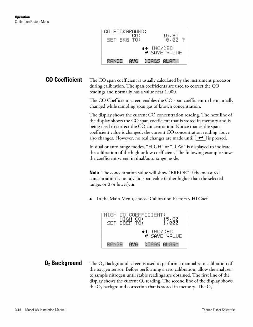
Operation Calibration Factors Menu
3-18 Model 48i Instruction Manual Thermo Fisher Scientific
CO BACKGROUND: CO: 15.80 SET BKG TO: 0.00 ? INC/DEC SAVE VALUE RANGE AVG DIAGS ALARM
The CO span coefficient is usually calculated by the instrument processor during calibration. The span coefficients are used to correct the CO readings and normally has a value near 1.000.
The CO Coefficient screen enables the CO span coefficient to be manually changed while sampling span gas of known concentration.
The display shows the current CO concentration reading. The next line of the display shows the CO span coefficient that is stored in memory and is being used to correct the CO concentration. Notice that as the span coefficient value is changed, the current CO concentration reading above also changes. However, no real changes are made until is pressed.
In dual or auto range modes, “HIGH” or “LOW” is displayed to indicate the calibration of the high or low coefficient. The following example shows the coefficient screen in dual/auto range mode.
Note The concentration value will show “ERROR” if the measured concentration is not a valid span value (either higher than the selected range, or 0 or lower). ▲
● In the Main Menu, choose Calibration Factors > Hi Coef.
HIGH CO COEFFICIENT: HIGH CO: 15.80 SET COEF TO: 1.000 INC/DEC SAVE VALUE RANGE AVG DIAGS ALARM
The O2 Background screen is used to perform a manual zero calibration of the oxygen sensor. Before performing a zero calibration, allow the analyzer to sample nitrogen until stable readings are obtained. The first line of the display shows the current O2 reading. The second line of the display shows the O2 background correction that is stored in memory. The O2
CO Coefficient
O2 Background
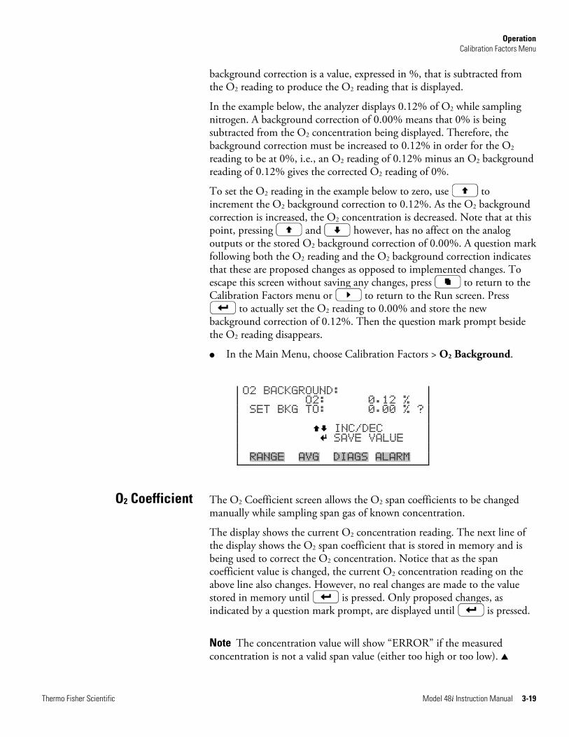
Operation Calibration Factors Menu
Thermo Fisher Scientific Model 48i Instruction Manual 3-19
background correction is a value, expressed in %, that is subtracted from the O2 reading to produce the O2 reading that is displayed.
In the example below, the analyzer displays 0.12% of O2 while sampling nitrogen. A background correction of 0.00% means that 0% is being subtracted from the O2 concentration being displayed. Therefore, the background correction must be increased to 0.12% in order for the O2 reading to be at 0%, i.e., an O2 reading of 0.12% minus an O2 background reading of 0.12% gives the corrected O2 reading of 0%.
To set the O2 reading in the example below to zero, use to increment the O2 background correction to 0.12%. As the O2 background correction is increased, the O2 concentration is decreased. Note that at this point, pressing and however, has no affect on the analog outputs or the stored O2 background correction of 0.00%. A question mark following both the O2 reading and the O2 background correction indicates that these are proposed changes as opposed to implemented changes. To escape this screen without saving any changes, press to return to the Calibration Factors menu or to return to the Run screen. Press
to actually set the O2 reading to 0.00% and store the new background correction of 0.12%. Then the question mark prompt beside the O2 reading disappears.
● In the Main Menu, choose Calibration Factors > O2 Background.
O2 BACKGROUND: O2: 0.12 % SET BKG TO: 0.00 % ? INC/DEC SAVE VALUE RANGE AVG DIAGS ALARM
The O2 Coefficient screen allows the O2 span coefficients to be changed manually while sampling span gas of known concentration.
The display shows the current O2 concentration reading. The next line of the display shows the O2 span coefficient that is stored in memory and is being used to correct the O2 concentration. Notice that as the span coefficient value is changed, the current O2 concentration reading on the above line also changes. However, no real changes are made to the value stored in memory until is pressed. Only proposed changes, as indicated by a question mark prompt, are displayed until is pressed.
Note The concentration value will show “ERROR” if the measured concentration is not a valid span value (either too high or too low). ▲
O2 Coefficient
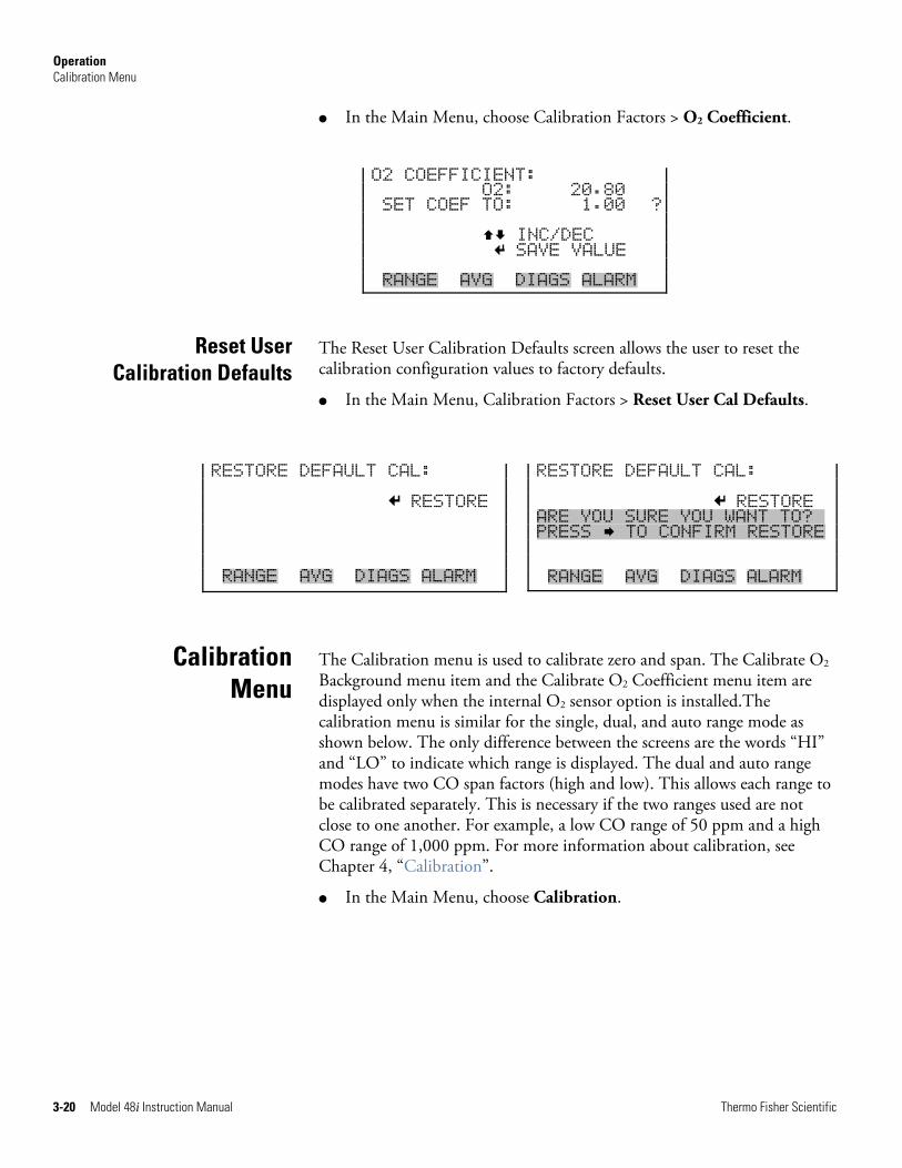
Operation Calibration Menu
3-20 Model 48i Instruction Manual Thermo Fisher Scientific
● In the Main Menu, choose Calibration Factors > O2 Coefficient.
O2 COEFFICIENT: O2: 20.80 SET COEF TO: 1.00 ? INC/DEC SAVE VALUE RANGE AVG DIAGS ALARM
The Reset User Calibration Defaults screen allows the user to reset the calibration configuration values to factory defaults.
● In the Main Menu, Calibration Factors > Reset User Cal Defaults.
The Calibration menu is used to calibrate zero and span. The Calibrate O2 Background menu item and the Calibrate O2 Coefficient menu item are displayed only when the internal O2 sensor option is installed.The calibration menu is similar for the single, dual, and auto range mode as shown below. The only difference between the screens are the words “HI” and “LO” to indicate which range is displayed. The dual and auto range modes have two CO span factors (high and low). This allows each range to be calibrated separately. This is necessary if the two ranges used are not close to one another. For example, a low CO range of 50 ppm and a high CO range of 1,000 ppm. For more information about calibration, see Chapter 4, “Calibration”.
● In the Main Menu, choose Calibration.
Reset User Calibration Defaults
Calibration Menu
RESTORE DEFAULT CAL: RESTORE RANGE AVG DIAGS ALARM
RESTORE DEFAULT CAL: RESTORE ARE YOU SURE YOU WANT TO?x PRESS TO CONFIRM RESTORE RANGE AVG DIAGS ALARM
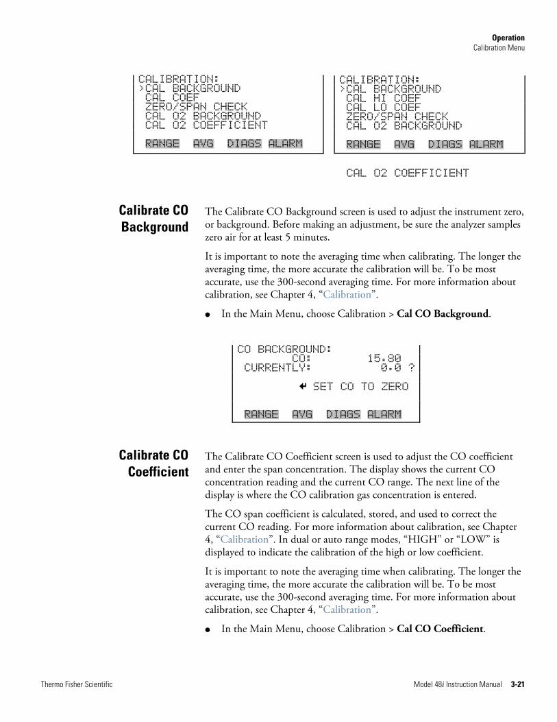
Operation Calibration Menu
Thermo Fisher Scientific Model 48i Instruction Manual 3-21
CAL O2 COEFFICIENT
The Calibrate CO Background screen is used to adjust the instrument zero, or background. Before making an adjustment, be sure the analyzer samples zero air for at least 5 minutes.
It is important to note the averaging time when calibrating. The longer the averaging time, the more accurate the calibration will be. To be most accurate, use the 300-second averaging time. For more information about calibration, see Chapter 4, “Calibration”.
● In the Main Menu, choose Calibration > Cal CO Background.
CO BACKGROUND: CO: 15.80 CURRENTLY: 0.0 ? SET CO TO ZERO RANGE AVG DIAGS ALARM
The Calibrate CO Coefficient screen is used to adjust the CO coefficient and enter the span concentration. The display shows the current CO concentration reading and the current CO range. The next line of the display is where the CO calibration gas concentration is entered.
The CO span coefficient is calculated, stored, and used to correct the current CO reading. For more information about calibration, see Chapter 4, “Calibration”. In dual or auto range modes, “HIGH” or “LOW” is displayed to indicate the calibration of the high or low coefficient.
It is important to note the averaging time when calibrating. The longer the averaging time, the more accurate the calibration will be. To be most accurate, use the 300-second averaging time. For more information about calibration, see Chapter 4, “Calibration”.
● In the Main Menu, choose Calibration > Cal CO Coefficient.
Calibrate CO Background
Calibrate CO Coefficient
CALIBRATION: >CAL BACKGROUND CAL COEF ZERO/SPAN CHECK CAL O2 BACKGROUND CAL O2 COEFFICIENT RANGE AVG DIAGS ALARM
CALIBRATION: >CAL BACKGROUND CAL HI COEF CAL LO COEF ZERO/SPAN CHECK CAL O2 BACKGROUND RANGE AVG DIAGS ALARM
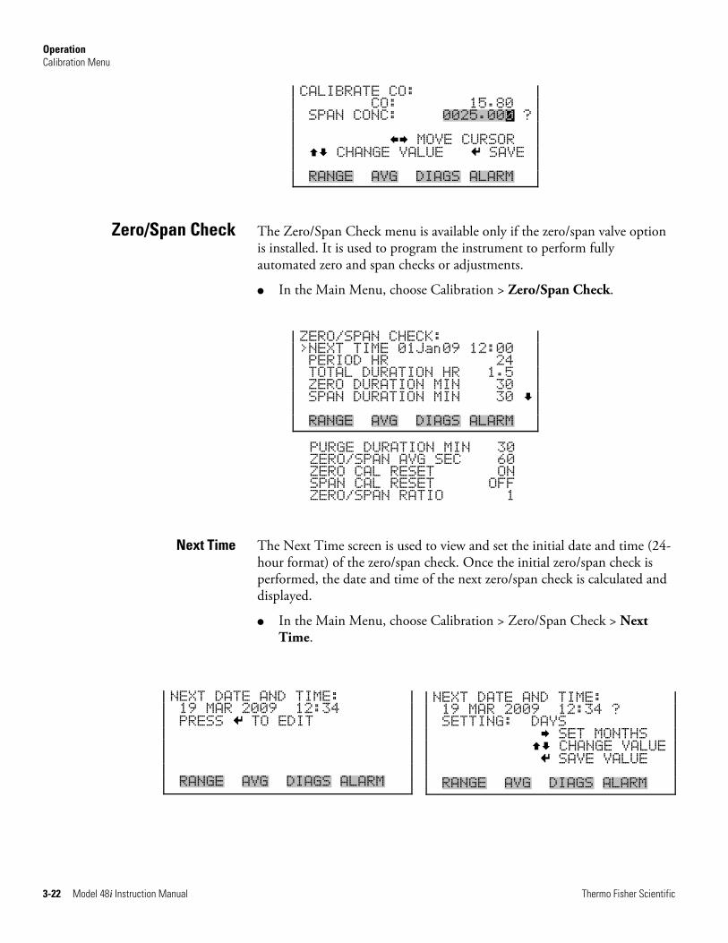
Operation Calibration Menu
3-22 Model 48i Instruction Manual Thermo Fisher Scientific
NEXT DATE AND TIME: 19 MAR 2009 12:34 ? SETTING: DAYS SET MONTHS CHANGE VALUE SAVE VALUE RANGE AVG DIAGS ALARM
CALIBRATE CO: CO: 15.80 SPAN CONC: 0025.000 ? MOVE CURSOR CHANGE VALUE SAVE RANGE AVG DIAGS ALARM
The Zero/Span Check menu is available only if the zero/span valve option is installed. It is used to program the instrument to perform fully automated zero and span checks or adjustments.
● In the Main Menu, choose Calibration > Zero/Span Check.
ZERO/SPAN CHECK: >NEXT TIME 01Jan09 12:00 PERIOD HR 24 TOTAL DURATION HR 1.5 ZERO DURATION MIN 30 SPAN DURATION MIN 30 RANGE AVG DIAGS ALARM
PURGE DURATION MIN 30 ZERO/SPAN AVG SEC 60 ZERO CAL RESET ON SPAN CAL RESET OFF ZERO/SPAN RATIO 1
The Next Time screen is used to view and set the initial date and time (24-hour format) of the zero/span check. Once the initial zero/span check is performed, the date and time of the next zero/span check is calculated and displayed.
● In the Main Menu, choose Calibration > Zero/Span Check > Next Time.
Zero/Span Check
Next Time
NEXT DATE AND TIME: 19 MAR 2009 12:34 PRESS TO EDIT RANGE AVG DIAGS ALARM
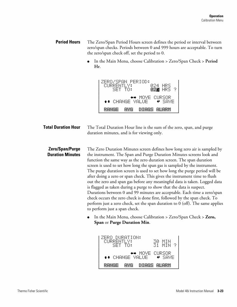
Operation Calibration Menu
Thermo Fisher Scientific Model 48i Instruction Manual 3-23
The Zero/Span Period Hours screen defines the period or interval between zero/span checks. Periods between 0 and 999 hours are acceptable. To turn the zero/span check off, set the period to 0.
● In the Main Menu, choose Calibration > Zero/Span Check > Period Hr.
ZERO/SPAN PERIOD: CURRENTLY: 024 HRS SET TO: 025 HRS ? MOVE CURSOR CHANGE VALUE SAVE RANGE AVG DIAGS ALARM
The Total Duration Hour line is the sum of the zero, span, and purge duration minutes, and is for viewing only.
The Zero Duration Minutes screen defines how long zero air is sampled by the instrument. The Span and Purge Duration Minutes screens look and function the same way as the zero duration screen. The span duration screen is used to set how long the span gas is sampled by the instrument. The purge duration screen is used to set how long the purge period will be after doing a zero or span check. This gives the instrument time to flush out the zero and span gas before any meaningful data is taken. Logged data is flagged as taken during a purge to show that the data is suspect. Durations between 0 and 99 minutes are acceptable. Each time a zero/span check occurs the zero check is done first, followed by the span check. To perform just a zero check, set the span duration to 0 (off). The same applies to perform just a span check.
● In the Main Menu, choose Calibration > Zero/Span Check > Zero, Span or Purge Duration Min.
ZERO DURATION: CURRENTLY: 30 MIN SET TO: 31 MIN ? MOVE CURSOR CHANGE VALUE SAVE RANGE AVG DIAGS ALARM
Period Hours
Total Duration Hour
Zero/Span/Purge Duration Minutes
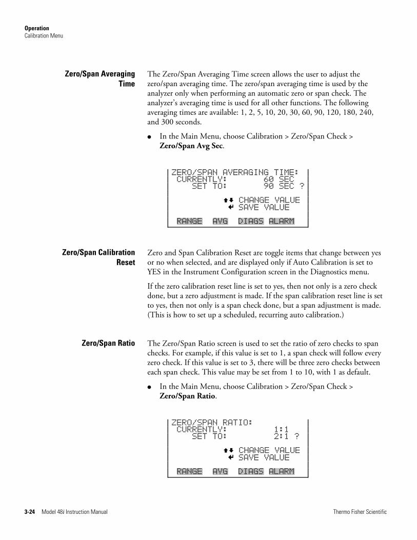
Operation Calibration Menu
3-24 Model 48i Instruction Manual Thermo Fisher Scientific
The Zero/Span Averaging Time screen allows the user to adjust the zero/span averaging time. The zero/span averaging time is used by the analyzer only when performing an automatic zero or span check. The analyzer’s averaging time is used for all other functions. The following averaging times are available: 1, 2, 5, 10, 20, 30, 60, 90, 120, 180, 240, and 300 seconds.
● In the Main Menu, choose Calibration > Zero/Span Check > Zero/Span Avg Sec.
ZERO/SPAN AVERAGING TIME: CURRENTLY: 60 SEC SET TO: 90 SEC ? CHANGE VALUE SAVE VALUE RANGE AVG DIAGS ALARM
Zero and Span Calibration Reset are toggle items that change between yes or no when selected, and are displayed only if Auto Calibration is set to YES in the Instrument Configuration screen in the Diagnostics menu.
If the zero calibration reset line is set to yes, then not only is a zero check done, but a zero adjustment is made. If the span calibration reset line is set to yes, then not only is a span check done, but a span adjustment is made. (This is how to set up a scheduled, recurring auto calibration.)
The Zero/Span Ratio screen is used to set the ratio of zero checks to span checks. For example, if this value is set to 1, a span check will follow every zero check. If this value is set to 3, there will be three zero checks between each span check. This value may be set from 1 to 10, with 1 as default.
● In the Main Menu, choose Calibration > Zero/Span Check > Zero/Span Ratio.
ZERO/SPAN RATIO: CURRENTLY: 1:1 SET TO: 2:1 ? CHANGE VALUE SAVE VALUE RANGE AVG DIAGS ALARM
Zero/Span Averaging Time
Zero/Span Calibration Reset
Zero/Span Ratio
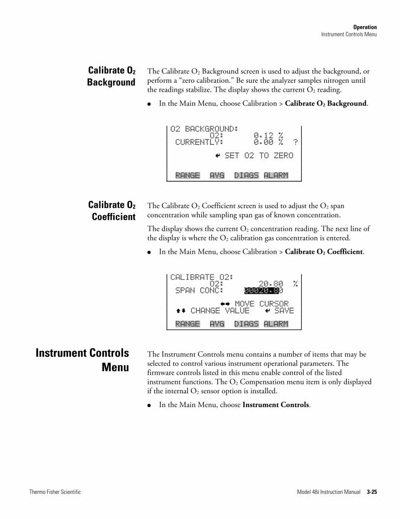
Operation Instrument Controls Menu
Thermo Fisher Scientific Model 48i Instruction Manual 3-25
The Calibrate O2 Background screen is used to adjust the background, or perform a “zero calibration.” Be sure the analyzer samples nitrogen until the readings stabilize. The display shows the current O2 reading.
● In the Main Menu, choose Calibration > Calibrate O2 Background.
O2 BACKGROUND: O2: 0.12 % CURRENTLY: 0.00 % ? SET O2 TO ZERO RANGE AVG DIAGS ALARM
The Calibrate O2 Coefficient screen is used to adjust the O2 span concentration while sampling span gas of known concentration.
The display shows the current O2 concentration reading. The next line of the display is where the O2 calibration gas concentration is entered.
● In the Main Menu, choose Calibration > Calibrate O2 Coefficient.
CALIBRATE O2: O2: 20.80 % SPAN CONC: 00020.80 MOVE CURSOR CHANGE VALUE SAVE RANGE AVG DIAGS ALARM
The Instrument Controls menu contains a number of items that may be selected to control various instrument operational parameters. The firmware controls listed in this menu enable control of the listed instrument functions. The O2 Compensation menu item is only displayed if the internal O2 sensor option is installed.
● In the Main Menu, choose Instrument Controls.
Calibrate O2 Background
Calibrate O2 Coefficient
Instrument Controls Menu
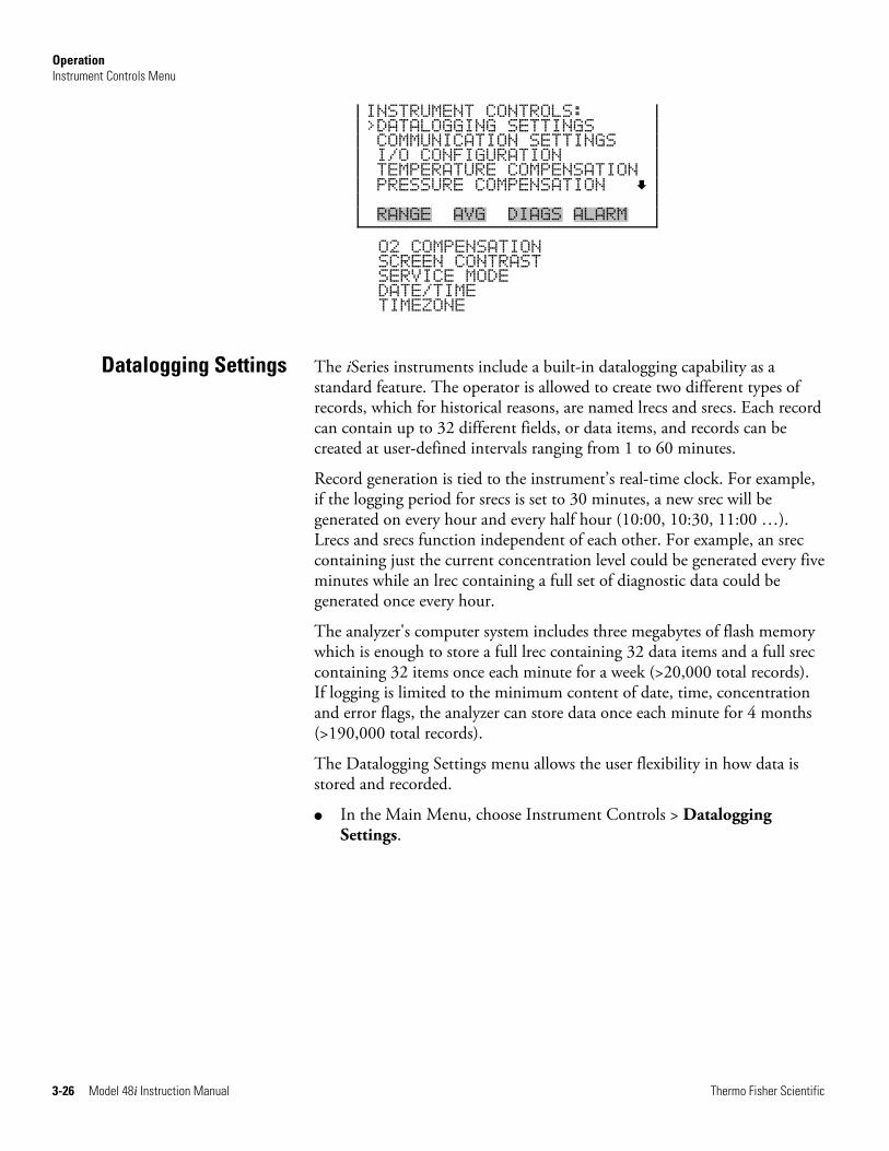
Operation Instrument Controls Menu
3-26 Model 48i Instruction Manual Thermo Fisher Scientific
INSTRUMENT CONTROLS: >DATALOGGING SETTINGS COMMUNICATION SETTINGS I/O CONFIGURATION TEMPERATURE COMPENSATION PRESSURE COMPENSATION RANGE AVG DIAGS ALARM
O2 COMPENSATION SCREEN CONTRAST SERVICE MODE DATE/TIME TIMEZONE
The iSeries instruments include a built-in datalogging capability as a standard feature. The operator is allowed to create two different types of records, which for historical reasons, are named lrecs and srecs. Each record can contain up to 32 different fields, or data items, and records can be created at user-defined intervals ranging from 1 to 60 minutes.
Record generation is tied to the instrument’s real-time clock. For example, if the logging period for srecs is set to 30 minutes, a new srec will be generated on every hour and every half hour (10:00, 10:30, 11:00 …). Lrecs and srecs function independent of each other. For example, an srec containing just the current concentration level could be generated every five minutes while an lrec containing a full set of diagnostic data could be generated once every hour.
The analyzer's computer system includes three megabytes of flash memory which is enough to store a full lrec containing 32 data items and a full srec containing 32 items once each minute for a week (>20,000 total records). If logging is limited to the minimum content of date, time, concentration and error flags, the analyzer can store data once each minute for 4 months (>190,000 total records).
The Datalogging Settings menu allows the user flexibility in how data is stored and recorded.
● In the Main Menu, choose Instrument Controls > Datalogging Settings.
Datalogging Settings
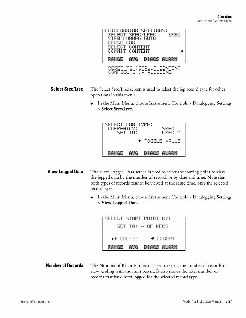
Operation Instrument Controls Menu
Thermo Fisher Scientific Model 48i Instruction Manual 3-27
DATALOGGING SETTINGS: >SELECT SREC/LREC SREC VIEW LOGGED DATA ERASE LOG SELECT CONTENT COMMIT CONTENT RANGE AVG DIAGS ALARM
RESET TO DEFAULT CONTENT CONFIGURE DATALOGGING
The Select Srec/Lrec screen is used to select the log record type for other operations in this menu.
● In the Main Menu, choose Instrument Controls > Datalogging Settings > Select Srec/Lrec.
SELECT LOG TYPE: CURRENTLY: SREC SET TO: LREC ? TOGGLE VALUE RANGE AVG DIAGS ALARM
The View Logged Data screen is used to select the starting point to view the logged data by the number of records or by date and time. Note that both types of records cannot be viewed at the same time, only the selected record type.
● In the Main Menu, choose Instrument Controls > Datalogging Settings > View Logged Data.
SELECT START POINT BY: SET TO: # OF RECS CHANGE ACCEPT RANGE AVG DIAGS ALARM
The Number of Records screen is used to select the number of records to view, ending with the most recent. It also shows the total number of records that have been logged for the selected record type.
Select Srec/Lrec
View Logged Data
Number of Records
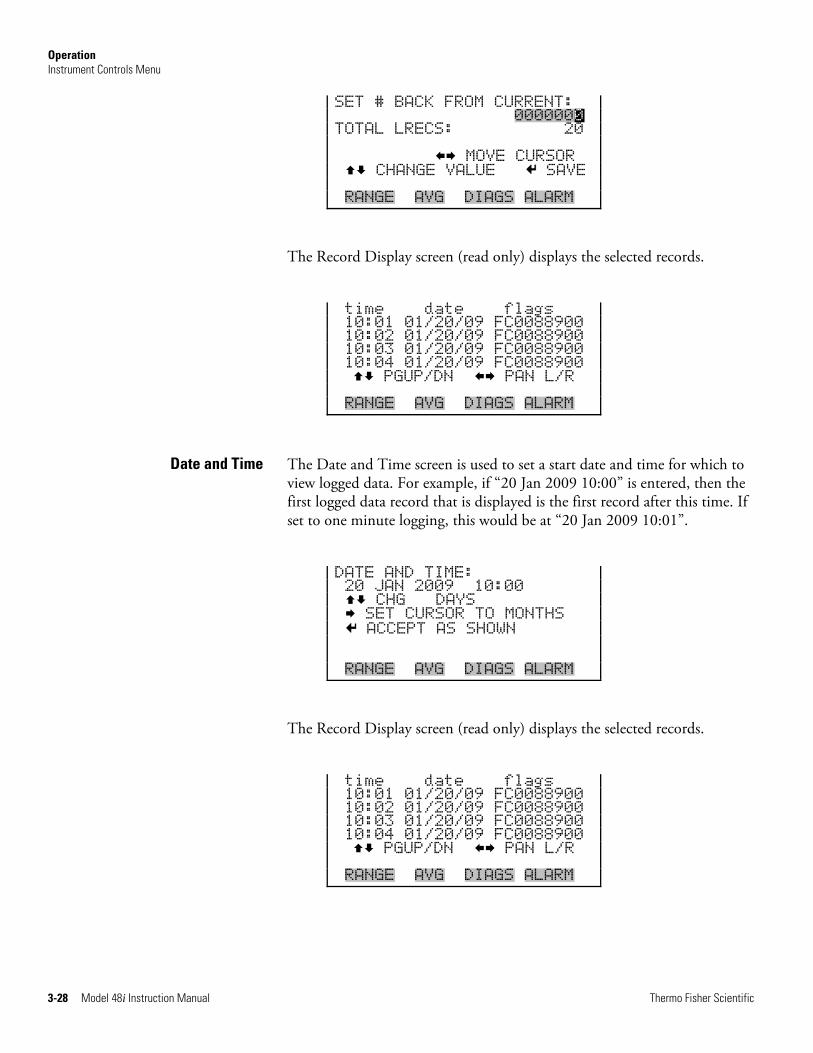
Operation Instrument Controls Menu
3-28 Model 48i Instruction Manual Thermo Fisher Scientific
SET # BACK FROM CURRENT: 0000000 TOTAL LRECS: 20 MOVE CURSOR CHANGE VALUE SAVE RANGE AVG DIAGS ALARM
The Record Display screen (read only) displays the selected records.
time date flags 10:01 01/20/09 FC0088900 10:02 01/20/09 FC0088900 10:03 01/20/09 FC0088900 10:04 01/20/09 FC0088900 PGUP/DN PAN L/R RANGE AVG DIAGS ALARM
The Date and Time screen is used to set a start date and time for which to view logged data. For example, if “20 Jan 2009 10:00” is entered, then the first logged data record that is displayed is the first record after this time. If set to one minute logging, this would be at “20 Jan 2009 10:01”.
DATE AND TIME: 20 JAN 2009 10:00 CHG DAYS SET CURSOR TO MONTHS ACCEPT AS SHOWN RANGE AVG DIAGS ALARM
The Record Display screen (read only) displays the selected records.
time date flags 10:01 01/20/09 FC0088900 10:02 01/20/09 FC0088900 10:03 01/20/09 FC0088900 10:04 01/20/09 FC0088900 PGUP/DN PAN L/R RANGE AVG DIAGS ALARM
Date and Time
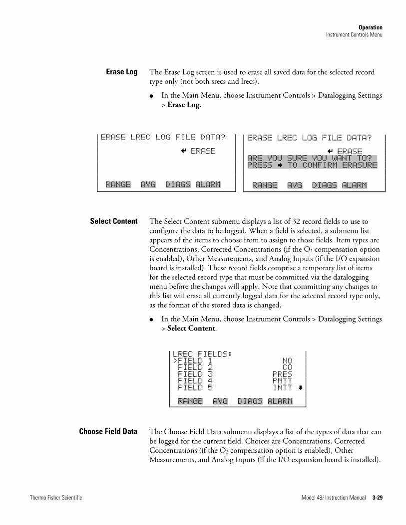
Operation Instrument Controls Menu
Thermo Fisher Scientific Model 48i Instruction Manual 3-29
ERASE LREC LOG FILE DATA? ERASE ARE YOU SURE YOU WANT TO?x PRESS TO CONFIRM ERASURE RANGE AVG DIAGS ALARM
The Erase Log screen is used to erase all saved data for the selected record type only (not both srecs and lrecs).
● In the Main Menu, choose Instrument Controls > Datalogging Settings > Erase Log.
The Select Content submenu displays a list of 32 record fields to use to configure the data to be logged. When a field is selected, a submenu list appears of the items to choose from to assign to those fields. Item types are Concentrations, Corrected Concentrations (if the O2 compensation option is enabled), Other Measurements, and Analog Inputs (if the I/O expansion board is installed). These record fields comprise a temporary list of items for the selected record type that must be committed via the datalogging menu before the changes will apply. Note that committing any changes to this list will erase all currently logged data for the selected record type only, as the format of the stored data is changed.
● In the Main Menu, choose Instrument Controls > Datalogging Settings > Select Content.
LREC FIELDS: >FIELD 1 NO FIELD 2 CO FIELD 3 PRES FIELD 4 PMTT FIELD 5 INTT RANGE AVG DIAGS ALARM
The Choose Field Data submenu displays a list of the types of data that can be logged for the current field. Choices are Concentrations, Corrected Concentrations (if the O2 compensation option is enabled), Other Measurements, and Analog Inputs (if the I/O expansion board is installed).
Erase Log
Select Content
Choose Field Data
ERASE LREC LOG FILE DATA? ERASE RANGE AVG DIAGS ALARM
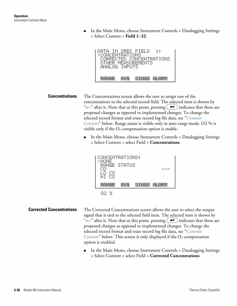
Operation Instrument Controls Menu
3-30 Model 48i Instruction Manual Thermo Fisher Scientific
● In the Main Menu, choose Instrument Controls > Datalogging Settings > Select Content > Field 1–32.
DATA IN SREC FIELD 1: >CONCENTRATIONS CORRECTED CONCENTRATIONS OTHER MEASUREMENTS ANALOG INPUTS RANGE AVG DIAGS ALARM
The Concentrations screen allows the user to assign one of the concentrations to the selected record field. The selected item is shown by “<--” after it. Note that at this point, pressing indicates that these are proposed changes as opposed to implemented changes. To change the selected record format and erase record log file data, see “Commit Content” below. Range status is visible only in auto range mode. O2 % is visible only if the O2 compensation option is enable.
● In the Main Menu, choose Instrument Controls > Datalogging Settings > Select Content > select Field > Concentrations.
CONCENTRATIONS: >NONE RANGE STATUS CO <-- LO CO HI CO RANGE AVG DIAGS ALARM
O2 %
The Corrected Concentrations screen allows the user to select the output signal that is tied to the selected field item. The selected item is shown by “<--” after it. Note that at this point, pressing indicates that these are proposed changes as opposed to implemented changes. To change the selected record format and erase record log file data, see “Commit Content” below. This screen is only displayed if the O2 compensation option is enabled.
● In the Main Menu, choose Instrument Controls > Datalogging Settings > Select Content > select Field > Corrected Concentrations.
Concentrations
Corrected Concentrations
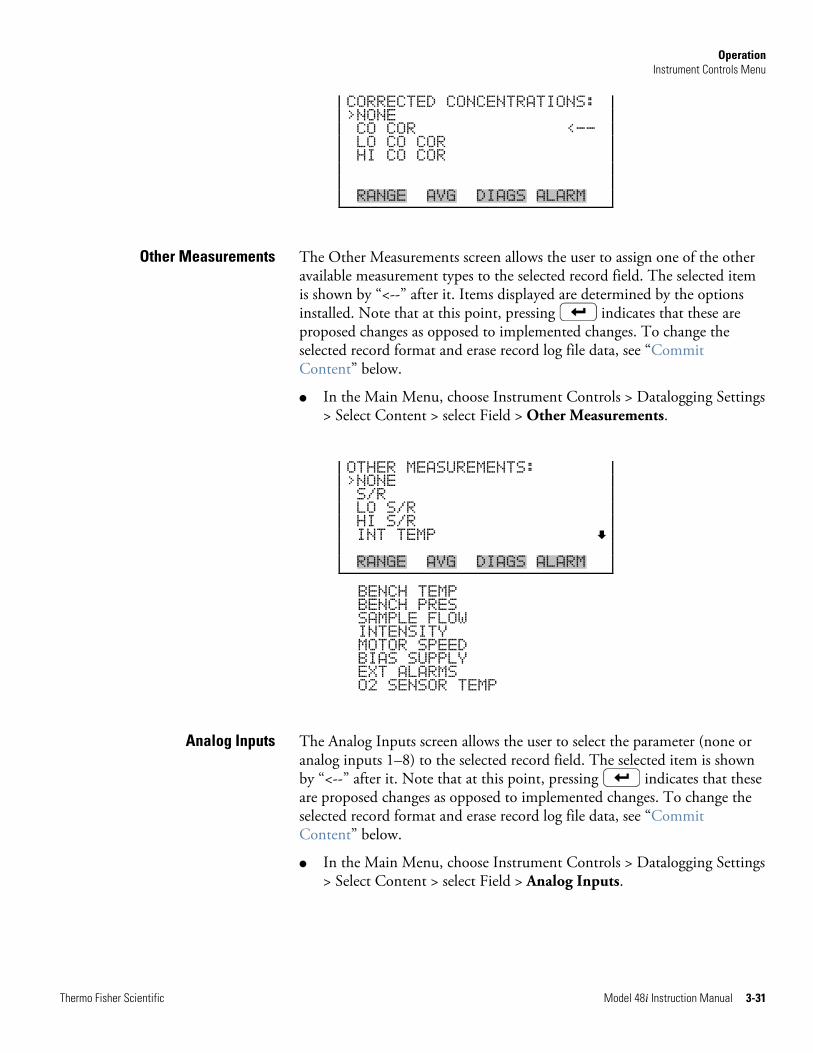
Operation Instrument Controls Menu
Thermo Fisher Scientific Model 48i Instruction Manual 3-31
CORRECTED CONCENTRATIONS: >NONE CO COR <-- LO CO COR HI CO COR RANGE AVG DIAGS ALARM
The Other Measurements screen allows the user to assign one of the other available measurement types to the selected record field. The selected item is shown by “<--” after it. Items displayed are determined by the options installed. Note that at this point, pressing indicates that these are proposed changes as opposed to implemented changes. To change the selected record format and erase record log file data, see “Commit Content” below.
● In the Main Menu, choose Instrument Controls > Datalogging Settings > Select Content > select Field > Other Measurements.
OTHER MEASUREMENTS: >NONE S/R LO S/R HI S/R INT TEMP RANGE AVG DIAGS ALARM
BENCH TEMP BENCH PRES SAMPLE FLOW INTENSITY MOTOR SPEED BIAS SUPPLY EXT ALARMS O2 SENSOR TEMP
The Analog Inputs screen allows the user to select the parameter (none or analog inputs 1–8) to the selected record field. The selected item is shown by “<--” after it. Note that at this point, pressing indicates that these are proposed changes as opposed to implemented changes. To change the selected record format and erase record log file data, see “Commit Content” below.
● In the Main Menu, choose Instrument Controls > Datalogging Settings > Select Content > select Field > Analog Inputs.
Other Measurements
Analog Inputs
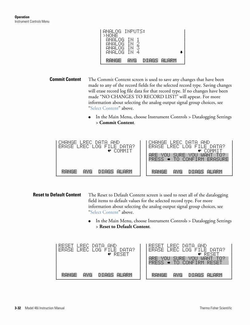
Operation Instrument Controls Menu
3-32 Model 48i Instruction Manual Thermo Fisher Scientific
ANALOG INPUTS: >NONE ANALOG IN 1 ANALOG IN 2 ANALOG IN 3 ANALOG IN 4 RANGE AVG DIAGS ALARM
The Commit Content screen is used to save any changes that have been made to any of the record fields for the selected record type. Saving changes will erase record log file data for that record type. If no changes have been made “NO CHANGES TO RECORD LIST!” will appear. For more information about selecting the analog output signal group choices, see “Select Content” above.
● In the Main Menu, choose Instrument Controls > Datalogging Settings > Commit Content.
The Reset to Default Content screen is used to reset all of the datalogging field items to default values for the selected record type. For more information about selecting the analog output signal group choices, see “Select Content” above.
● In the Main Menu, choose Instrument Controls > Datalogging Settings > Reset to Default Content.
Commit Content
Reset to Default Content
CHANGE LREC DATA AND ERASE LREC LOG FILE DATA? COMMIT RANGE AVG DIAGS ALARM
CHANGE LREC DATA AND ERASE LREC LOG FILE DATA? COMMIT ARE YOU SURE YOU WANT TO?x PRESS TO CONFIRM ERASURE RANGE AVG DIAGS ALARM
RESET LREC DATA AND ERASE LREC LOG FILE DATA? RESET RANGE AVG DIAGS ALARM
RESET LREC DATA AND ERASE LREC LOG FILE DATA? RESET ARE YOU SURE YOU WANT TO?x PRESS TO CONFIRM RESETxx RANGE AVG DIAGS ALARM
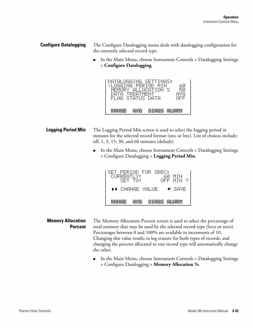
Operation Instrument Controls Menu
Thermo Fisher Scientific Model 48i Instruction Manual 3-33
The Configure Datalogging menu deals with datalogging configuration for the currently selected record type.
● In the Main Menu, choose Instrument Controls > Datalogging Settings > Configure Datalogging.
DATALOGGING SETTINGS: >LOGGING PERIOD MIN 60 MEMORY ALLOCATION % 50 DATA TREATMENT AVG FLAG STATUS DATA OFF RANGE AVG DIAGS ALARM
The Logging Period Min screen is used to select the logging period in minutes for the selected record format (srec or lrec). List of choices include: off, 1, 5, 15, 30, and 60 minutes (default).
● In the Main Menu, choose Instrument Controls > Datalogging Settings > Configure Datalogging > Logging Period Min.
SET PERIOD FOR SREC: CURRENTLY: 60 MIN SET TO: OFF MIN ? CHANGE VALUE SAVE RANGE AVG DIAGS ALARM
The Memory Allocation Percent screen is used to select the percentage of total memory that may be used by the selected record type (lrecs or srecs). Percentages between 0 and 100% are available in increments of 10. Changing this value results in log erasure for both types of records, and changing the percent allocated to one record type will automatically change the other.
● In the Main Menu, choose Instrument Controls > Datalogging Settings > Configure Datalogging > Memory Allocation %.
Configure Datalogging
Logging Period Min
Memory Allocation Percent
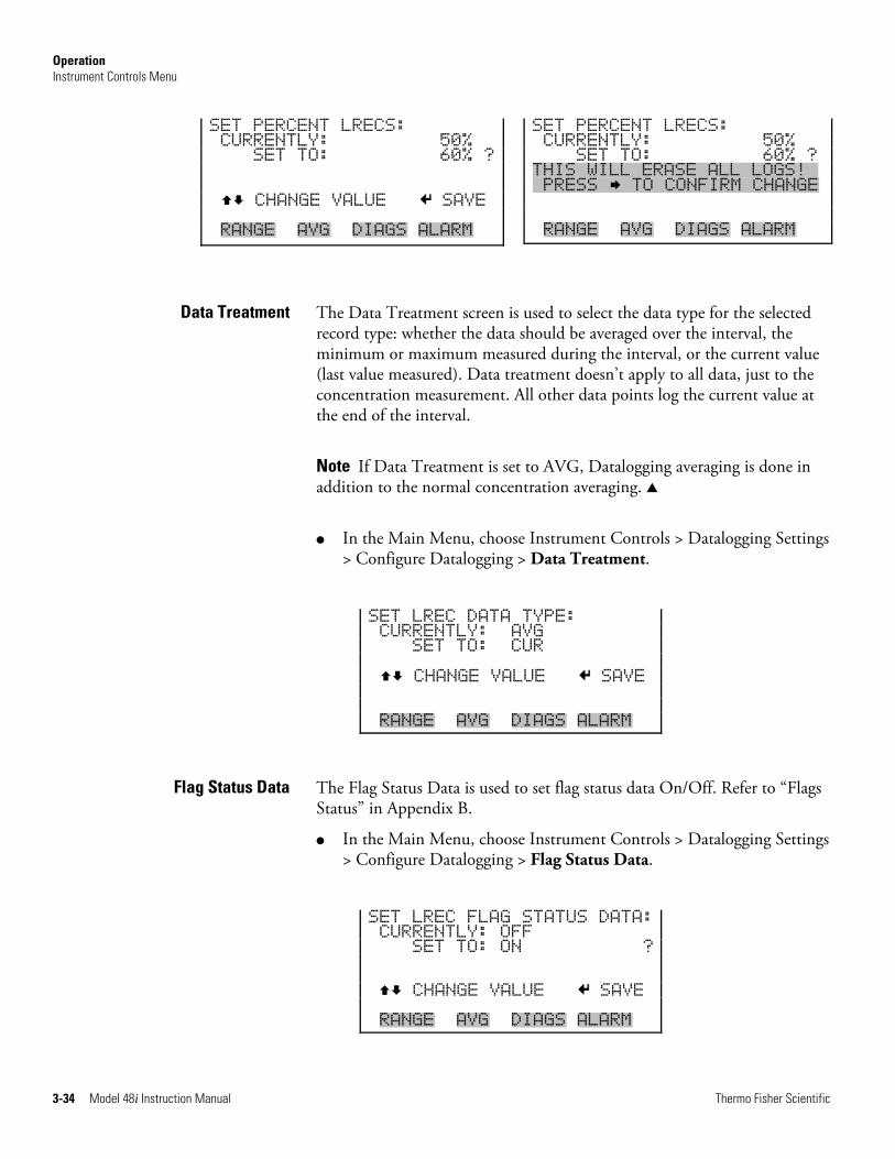
Operation Instrument Controls Menu
3-34 Model 48i Instruction Manual Thermo Fisher Scientific
The Data Treatment screen is used to select the data type for the selected record type: whether the data should be averaged over the interval, the minimum or maximum measured during the interval, or the current value (last value measured). Data treatment doesn’t apply to all data, just to the concentration measurement. All other data points log the current value at the end of the interval.
Note If Data Treatment is set to AVG, Datalogging averaging is done in addition to the normal concentration averaging. ▲
● In the Main Menu, choose Instrument Controls > Datalogging Settings > Configure Datalogging > Data Treatment.
SET LREC DATA TYPE: CURRENTLY: AVG SET TO: CUR CHANGE VALUE SAVE RANGE AVG DIAGS ALARM
The Flag Status Data is used to set flag status data On/Off. Refer to “Flags Status” in Appendix B.
● In the Main Menu, choose Instrument Controls > Datalogging Settings > Configure Datalogging > Flag Status Data.
SET LREC FLAG STATUS DATA: CURRENTLY: OFF SET TO: ON ? CHANGE VALUE SAVE RANGE AVG DIAGS ALARM
Data Treatment
Flag Status Data
SET PERCENT LRECS: CURRENTLY: 50% SET TO: 60% ? CHANGE VALUE SAVE RANGE AVG DIAGS ALARM
SET PERCENT LRECS: CURRENTLY: 50% SET TO: 60% ? THIS WILL ERASE ALL LOGS!x PRESS TO CONFIRM CHANGE RANGE AVG DIAGS ALARM
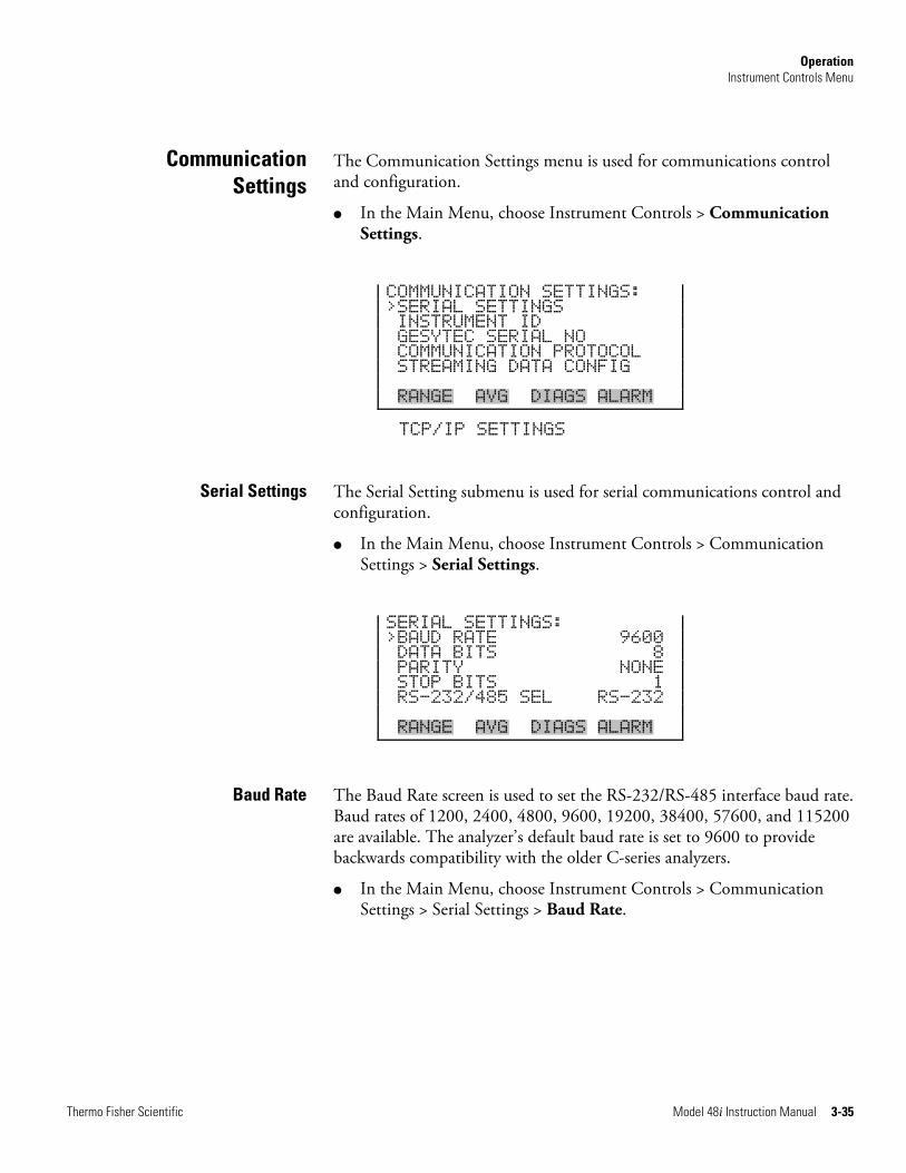
Operation Instrument Controls Menu
Thermo Fisher Scientific Model 48i Instruction Manual 3-35
The Communication Settings menu is used for communications control and configuration.
● In the Main Menu, choose Instrument Controls > Communication Settings.
COMMUNICATION SETTINGS: >SERIAL SETTINGS INSTRUMENT ID GESYTEC SERIAL NO COMMUNICATION PROTOCOL STREAMING DATA CONFIG RANGE AVG DIAGS ALARM
TCP/IP SETTINGS
The Serial Setting submenu is used for serial communications control and configuration.
● In the Main Menu, choose Instrument Controls > Communication Settings > Serial Settings.
SERIAL SETTINGS: >BAUD RATE 9600 DATA BITS 8 PARITY NONE STOP BITS 1 RS-232/485 SEL RS-232 RANGE AVG DIAGS ALARM
The Baud Rate screen is used to set the RS-232/RS-485 interface baud rate. Baud rates of 1200, 2400, 4800, 9600, 19200, 38400, 57600, and 115200 are available. The analyzer’s default baud rate is set to 9600 to provide backwards compatibility with the older C-series analyzers.
● In the Main Menu, choose Instrument Controls > Communication Settings > Serial Settings > Baud Rate.
Communication Settings
Serial Settings
Baud Rate
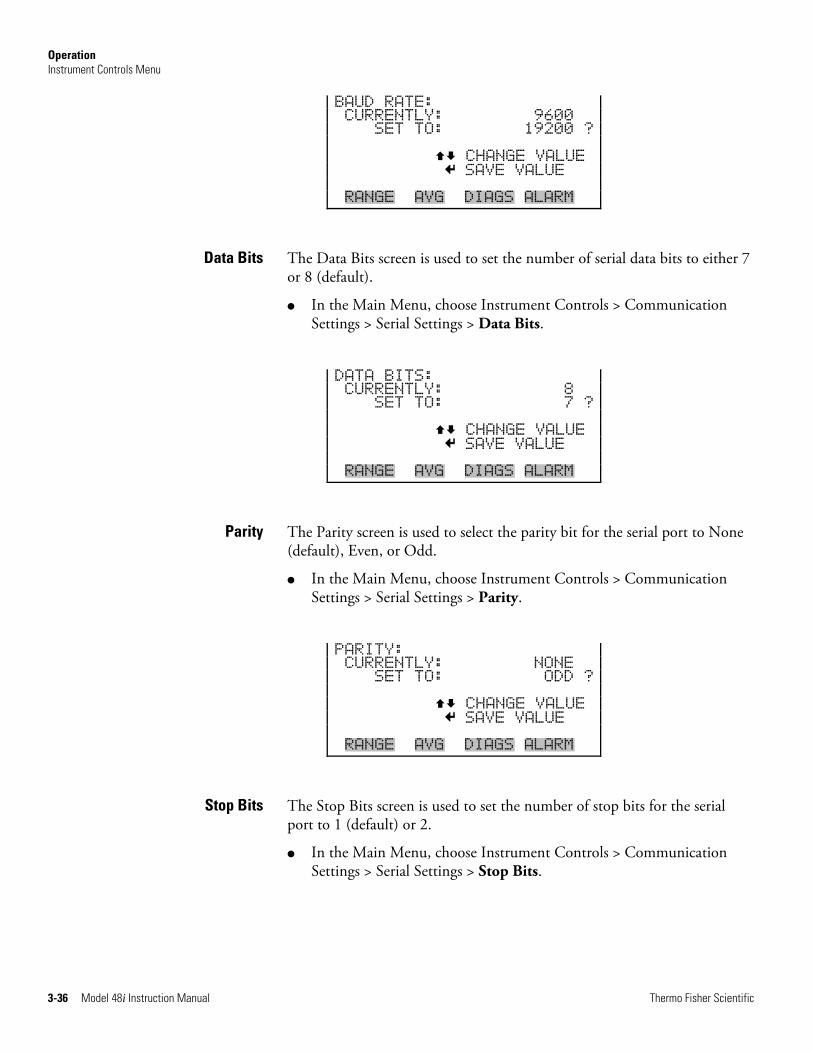
Operation Instrument Controls Menu
3-36 Model 48i Instruction Manual Thermo Fisher Scientific
BAUD RATE: CURRENTLY: 9600 SET TO: 19200 ? CHANGE VALUE SAVE VALUE RANGE AVG DIAGS ALARM
The Data Bits screen is used to set the number of serial data bits to either 7 or 8 (default).
● In the Main Menu, choose Instrument Controls > Communication Settings > Serial Settings > Data Bits.
DATA BITS: CURRENTLY: 8 SET TO: 7 ? CHANGE VALUE SAVE VALUE RANGE AVG DIAGS ALARM
The Parity screen is used to select the parity bit for the serial port to None (default), Even, or Odd.
● In the Main Menu, choose Instrument Controls > Communication Settings > Serial Settings > Parity.
PARITY: CURRENTLY: NONE SET TO: ODD ? CHANGE VALUE SAVE VALUE RANGE AVG DIAGS ALARM
The Stop Bits screen is used to set the number of stop bits for the serial port to 1 (default) or 2.
● In the Main Menu, choose Instrument Controls > Communication Settings > Serial Settings > Stop Bits.
Data Bits
Parity
Stop Bits
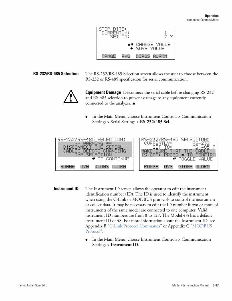
Operation Instrument Controls Menu
Thermo Fisher Scientific Model 48i Instruction Manual 3-37
STOP BITS: CURRENTLY: 1 SET TO: 2 ? CHANGE VALUE SAVE VALUE RANGE AVG DIAGS ALARM
The RS-232/RS-485 Selection screen allows the user to choose between the RS-232 or RS-485 specification for serial communication.
Equipment Damage Disconnect the serial cable before changing RS-232 and RS-485 selection to prevent damage to any equipment currently connected to the analyzer. ▲
● In the Main Menu, choose Instrument Controls > Communication Settings > Serial Settings > RS-232/485 Sel.
The Instrument ID screen allows the operator to edit the instrument identification number (ID). The ID is used to identify the instrument when using the C-Link or MODBUS protocols to control the instrument or collect data. It may be necessary to edit the ID number if two or more of instruments of the same model are connected to one computer. Valid instrument ID numbers are from 0 to 127. The Model 48i has a default instrument ID of 48. For more information about the Instrument ID, see Appendix B “C-Link Protocol Commands” or Appendix C “MODBUS Protocol”.
● In the Main Menu, choose Instrument Controls > Communication Settings > Instrument ID.
RS-232/RS-485 Selection
Instrument ID
RS-232/RS-485 SELECTION: XXXXXX** WARNING **XXXXXXX DISCONNECT THE SERIALX X CABLES BEFORE CHANGING X THE SELECTION!XXXXXX TO CONTINUE RANGE AVG DIAGS ALARM
RS-232/RS-485 SELECTION: CURRENTLY: RS-232 SET TO: RS-485 ? MAKE SURE THAT THE CABLEXX IS OFF: PRESS TO CONFIRM TOGGLE VALUE RANGE AVG DIAGS ALARM
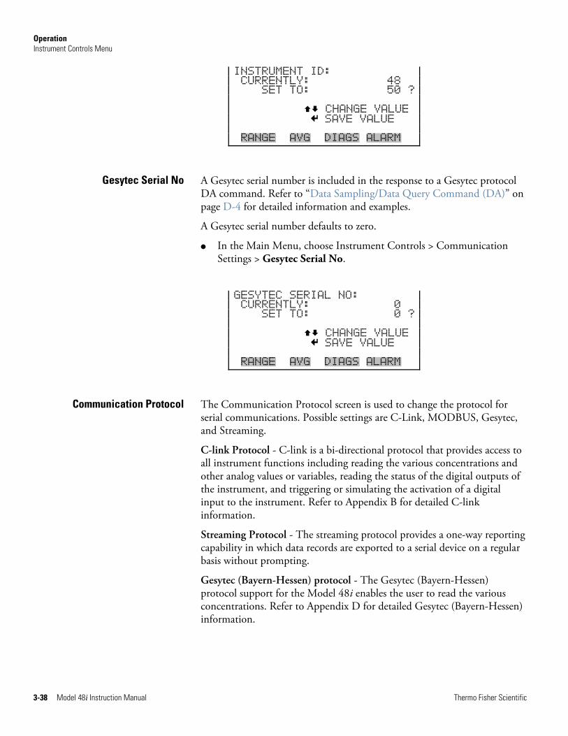
Operation Instrument Controls Menu
3-38 Model 48i Instruction Manual Thermo Fisher Scientific
INSTRUMENT ID: CURRENTLY: 48 SET TO: 50 ? CHANGE VALUE SAVE VALUE RANGE AVG DIAGS ALARM
A Gesytec serial number is included in the response to a Gesytec protocol DA command. Refer to “Data Sampling/Data Query Command (DA)” on page D-4 for detailed information and examples.
A Gesytec serial number defaults to zero.
● In the Main Menu, choose Instrument Controls > Communication Settings > Gesytec Serial No.
GESYTEC SERIAL NO: CURRENTLY: 0 SET TO: 0 ? CHANGE VALUE SAVE VALUE RANGE AVG DIAGS ALARM
The Communication Protocol screen is used to change the protocol for serial communications. Possible settings are C-Link, MODBUS, Gesytec, and Streaming.
C-link Protocol - C-link is a bi-directional protocol that provides access to all instrument functions including reading the various concentrations and other analog values or variables, reading the status of the digital outputs of the instrument, and triggering or simulating the activation of a digital input to the instrument. Refer to Appendix B for detailed C-link information.
Streaming Protocol - The streaming protocol provides a one-way reporting capability in which data records are exported to a serial device on a regular basis without prompting.
Gesytec (Bayern-Hessen) protocol - The Gesytec (Bayern-Hessen) protocol support for the Model 48i enables the user to read the various concentrations. Refer to Appendix D for detailed Gesytec (Bayern-Hessen) information.
Gesytec Serial No
Communication Protocol
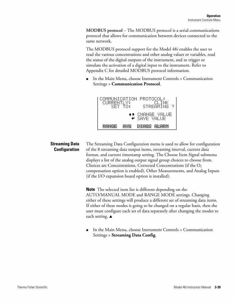
Operation Instrument Controls Menu
Thermo Fisher Scientific Model 48i Instruction Manual 3-39
MODBUS protocol – The MODBUS protocol is a serial communications protocol that allows for communication between devices connected to the same network.
The MODBUS protocol support for the Model 48i enables the user to read the various concentrations and other analog values or variables, read the status of the digital outputs of the instrument, and to trigger or simulate the activation of a digital input to the instrument. Refer to Appendix C for detailed MODBUS protocol information.
● In the Main Menu, choose Instrument Controls > Communication Settings > Communication Protocol.
COMMUNICATION PROTOCOL: CURRENTLY: CLINK SET TO: STREAMING ? CHANGE VALUE SAVE VALUE RANGE AVG DIAGS ALARM
The Streaming Data Configuration menu is used to allow for configuration of the 8 streaming data output items, streaming interval, current data format, and current timestamp setting. The Choose Item Signal submenu displays a list of the analog output signal group choices to choose from. Choices are Concentrations, Corrected Concentrations (if the O2 compensation option is enabled), Other Measurements, and Analog Inputs (if the I/O expansion board option is installed).
Note The selected item list is different depending on the AUTO/MANUAL MODE and RANGE MODE settings. Changing either of these settings will produce a different set of streaming data items. If either of these modes is going to be changed on a regular basis, then the user must configure each set of data separately after changing the modes to each setting. ▲
● In the Main Menu, choose Instrument Controls > Communication Settings > Streaming Data Config.
Streaming Data Configuration
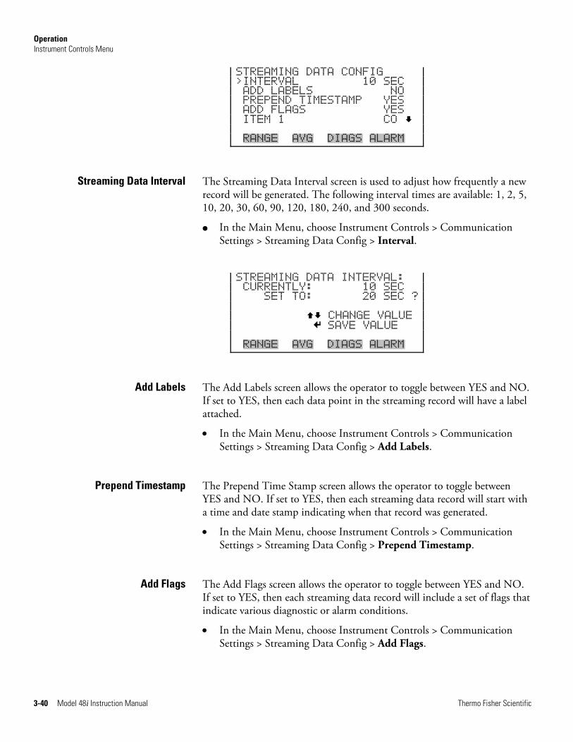
Operation Instrument Controls Menu
3-40 Model 48i Instruction Manual Thermo Fisher Scientific
STREAMING DATA CONFIG >INTERVAL 10 SEC ADD LABELS NO PREPEND TIMESTAMP YES ADD FLAGS YES ITEM 1 CO RANGE AVG DIAGS ALARM
The Streaming Data Interval screen is used to adjust how frequently a new record will be generated. The following interval times are available: 1, 2, 5, 10, 20, 30, 60, 90, 120, 180, 240, and 300 seconds.
● In the Main Menu, choose Instrument Controls > Communication Settings > Streaming Data Config > Interval.
STREAMING DATA INTERVAL: CURRENTLY: 10 SEC SET TO: 20 SEC ? CHANGE VALUE SAVE VALUE RANGE AVG DIAGS ALARM
The Add Labels screen allows the operator to toggle between YES and NO. If set to YES, then each data point in the streaming record will have a label attached.
• In the Main Menu, choose Instrument Controls > Communication Settings > Streaming Data Config > Add Labels.
The Prepend Time Stamp screen allows the operator to toggle between YES and NO. If set to YES, then each streaming data record will start with a time and date stamp indicating when that record was generated.
• In the Main Menu, choose Instrument Controls > Communication Settings > Streaming Data Config > Prepend Timestamp.
The Add Flags screen allows the operator to toggle between YES and NO. If set to YES, then each streaming data record will include a set of flags that indicate various diagnostic or alarm conditions.
• In the Main Menu, choose Instrument Controls > Communication Settings > Streaming Data Config > Add Flags.
Streaming Data Interval
Add Labels
Prepend Timestamp
Add Flags
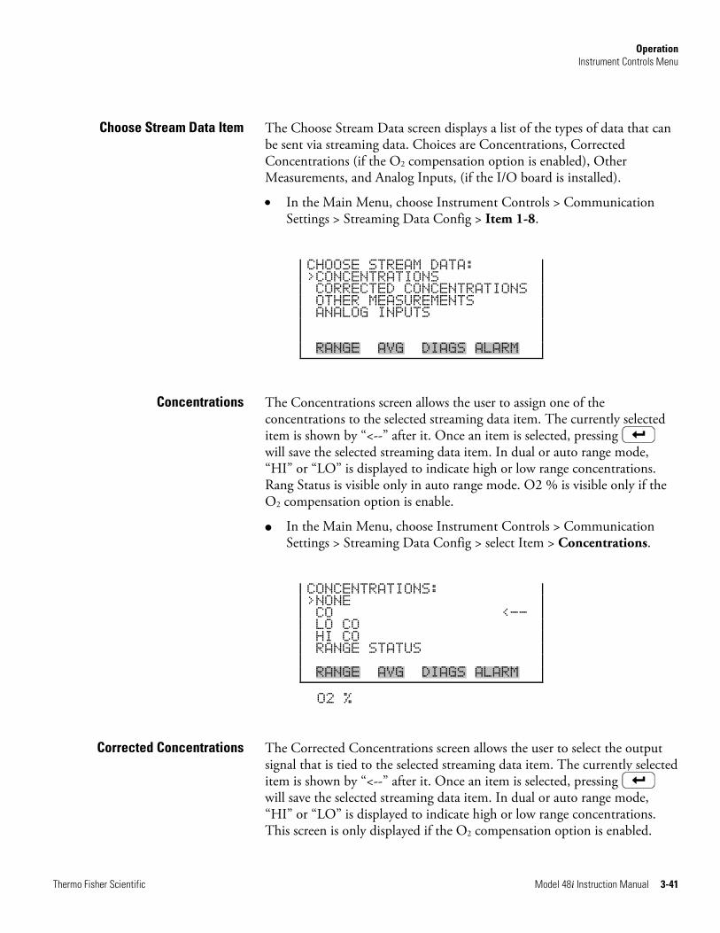
Operation Instrument Controls Menu
Thermo Fisher Scientific Model 48i Instruction Manual 3-41
The Choose Stream Data screen displays a list of the types of data that can be sent via streaming data. Choices are Concentrations, Corrected Concentrations (if the O2 compensation option is enabled), Other Measurements, and Analog Inputs, (if the I/O board is installed).
• In the Main Menu, choose Instrument Controls > Communication Settings > Streaming Data Config > Item 1-8.
CHOOSE STREAM DATA: >CONCENTRATIONS CORRECTED CONCENTRATIONS OTHER MEASUREMENTS ANALOG INPUTS RANGE AVG DIAGS ALARM
The Concentrations screen allows the user to assign one of the concentrations to the selected streaming data item. The currently selected item is shown by “<--” after it. Once an item is selected, pressing will save the selected streaming data item. In dual or auto range mode, “HI” or “LO” is displayed to indicate high or low range concentrations. Rang Status is visible only in auto range mode. O2 % is visible only if the O2 compensation option is enable.
● In the Main Menu, choose Instrument Controls > Communication Settings > Streaming Data Config > select Item > Concentrations.
CONCENTRATIONS: >NONE CO <-- LO CO HI CO RANGE STATUS RANGE AVG DIAGS ALARM
O2 %
The Corrected Concentrations screen allows the user to select the output signal that is tied to the selected streaming data item. The currently selected item is shown by “<--” after it. Once an item is selected, pressing will save the selected streaming data item. In dual or auto range mode, “HI” or “LO” is displayed to indicate high or low range concentrations. This screen is only displayed if the O2 compensation option is enabled.
Choose Stream Data Item
Concentrations
Corrected Concentrations
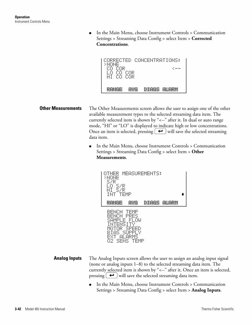
Operation Instrument Controls Menu
3-42 Model 48i Instruction Manual Thermo Fisher Scientific
● In the Main Menu, choose Instrument Controls > Communication Settings > Streaming Data Config > select Item > Corrected Concentrations.
CORRECTED CONCENTRATIONS: >NONE CO COR <-- LO CO COR HI CO COR RANGE AVG DIAGS ALARM
The Other Measurements screen allows the user to assign one of the other available measurement types to the selected streaming data item. The currently selected item is shown by “<--” after it. In dual or auto range mode, “HI” or “LO” is displayed to indicate high or low concentrations. Once an item is selected, pressing will save the selected streaming data item.
● In the Main Menu, choose Instrument Controls > Communication Settings > Streaming Data Config > select Item > Other Measurements.
OTHER MEASUREMENTS: >NONE S/R LO S/R HI S/R INT TEMP RANGE AVG DIAGS ALARM
BENCH TEMP BENCH PRES SAMPLE FLOW INTENSITY MOTOR SPEED BIAS SUPPLY EXT ALARMS O2 SENS TEMP
The Analog Inputs screen allows the user to assign an analog input signal (none or analog inputs 1–8) to the selected streaming data item. The currently selected item is shown by “<--” after it. Once an item is selected, pressing will save the selected streaming data item.
● In the Main Menu, choose Instrument Controls > Communication Settings > Streaming Data Config > select Item > Analog Inputs.
Other Measurements
Analog Inputs
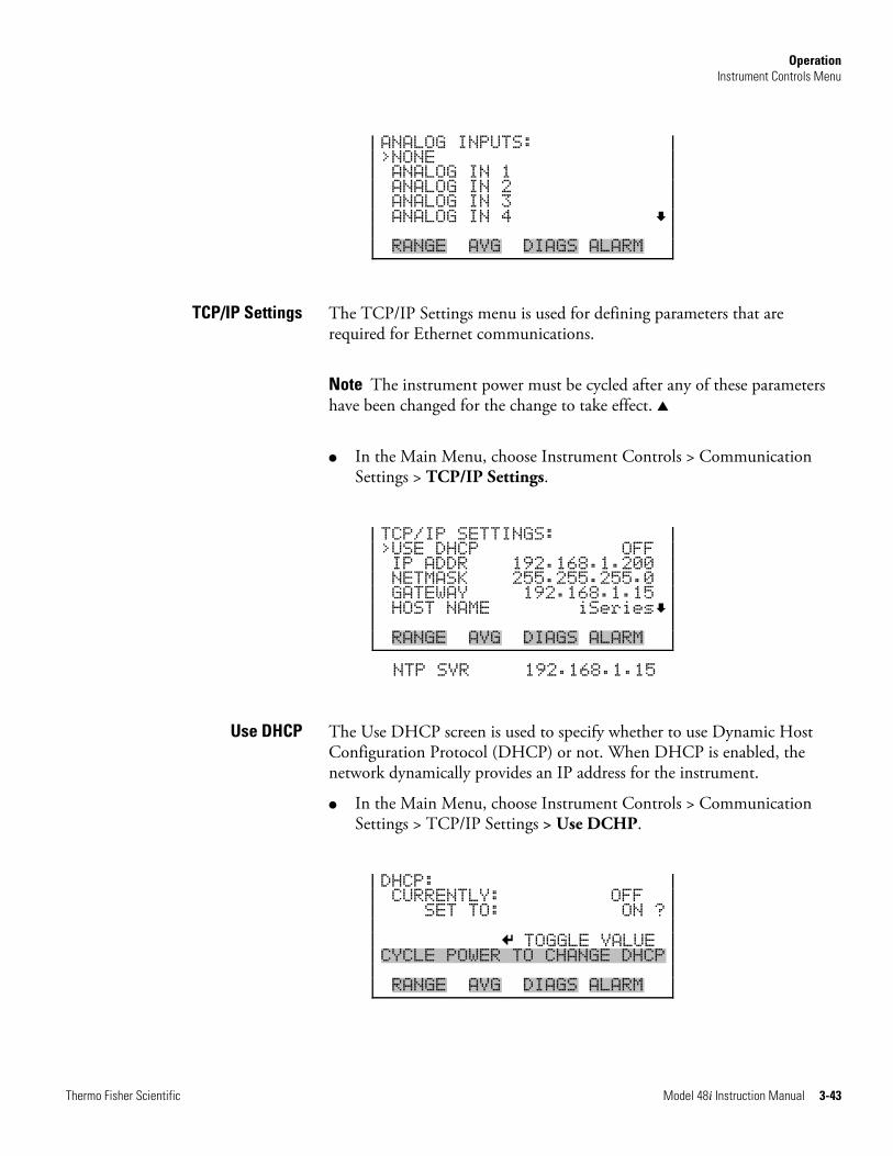
Operation Instrument Controls Menu
Thermo Fisher Scientific Model 48i Instruction Manual 3-43
ANALOG INPUTS: >NONE ANALOG IN 1 ANALOG IN 2 ANALOG IN 3 ANALOG IN 4 RANGE AVG DIAGS ALARM
The TCP/IP Settings menu is used for defining parameters that are required for Ethernet communications.
Note The instrument power must be cycled after any of these parameters have been changed for the change to take effect. ▲
● In the Main Menu, choose Instrument Controls > Communication Settings > TCP/IP Settings.
TCP/IP SETTINGS: >USE DHCP OFF IP ADDR 192.168.1.200 NETMASK 255.255.255.0 GATEWAY 192.168.1.15 HOST NAME iSeries RANGE AVG DIAGS ALARM
NTP SVR 192.168.1.15
The Use DHCP screen is used to specify whether to use Dynamic Host Configuration Protocol (DHCP) or not. When DHCP is enabled, the network dynamically provides an IP address for the instrument.
● In the Main Menu, choose Instrument Controls > Communication Settings > TCP/IP Settings > Use DCHP.
DHCP: CURRENTLY: OFF SET TO: ON ? TOGGLE VALUE CYCLE POWER TO CHANGE DHCP RANGE AVG DIAGS ALARM
TCP/IP Settings
Use DHCP
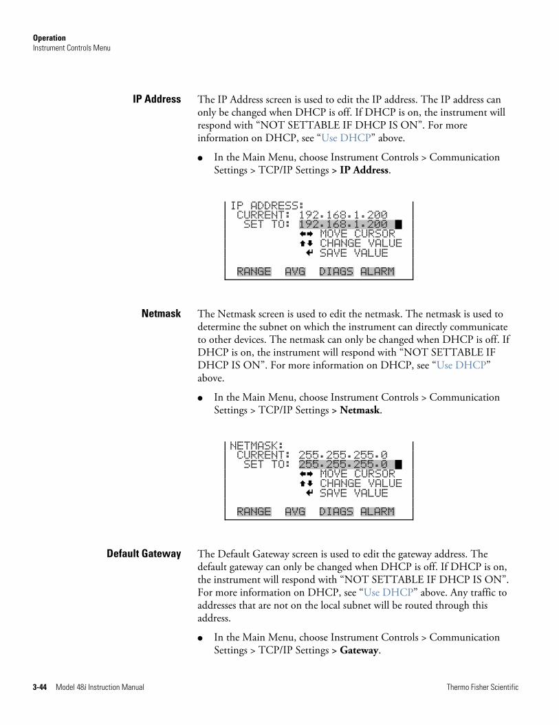
Operation Instrument Controls Menu
3-44 Model 48i Instruction Manual Thermo Fisher Scientific
The IP Address screen is used to edit the IP address. The IP address can only be changed when DHCP is off. If DHCP is on, the instrument will respond with “NOT SETTABLE IF DHCP IS ON”. For more information on DHCP, see “Use DHCP” above.
● In the Main Menu, choose Instrument Controls > Communication Settings > TCP/IP Settings > IP Address.
IP ADDRESS: CURRENT: 192.168.1.200 SET TO: 192.168.1.200 1 MOVE CURSOR CHANGE VALUE SAVE VALUE RANGE AVG DIAGS ALARM
The Netmask screen is used to edit the netmask. The netmask is used to determine the subnet on which the instrument can directly communicate to other devices. The netmask can only be changed when DHCP is off. If DHCP is on, the instrument will respond with “NOT SETTABLE IF DHCP IS ON”. For more information on DHCP, see “Use DHCP” above.
● In the Main Menu, choose Instrument Controls > Communication Settings > TCP/IP Settings > Netmask.
NETMASK: CURRENT: 255.255.255.0 SET TO: 255.255.255.0 0 MOVE CURSOR CHANGE VALUE SAVE VALUE RANGE AVG DIAGS ALARM
The Default Gateway screen is used to edit the gateway address. The default gateway can only be changed when DHCP is off. If DHCP is on, the instrument will respond with “NOT SETTABLE IF DHCP IS ON”. For more information on DHCP, see “Use DHCP” above. Any traffic to addresses that are not on the local subnet will be routed through this address.
● In the Main Menu, choose Instrument Controls > Communication Settings > TCP/IP Settings > Gateway.
IP Address
Netmask
Default Gateway
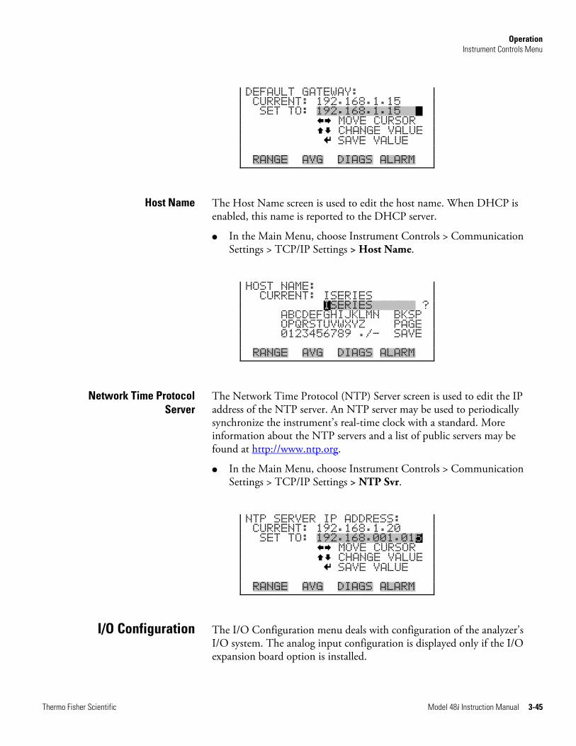
Operation Instrument Controls Menu
Thermo Fisher Scientific Model 48i Instruction Manual 3-45
DEFAULT GATEWAY: CURRENT: 192.168.1.15 SET TO: 192.168.1.15 1 MOVE CURSOR CHANGE VALUE SAVE VALUE RANGE AVG DIAGS ALARM
The Host Name screen is used to edit the host name. When DHCP is enabled, this name is reported to the DHCP server.
● In the Main Menu, choose Instrument Controls > Communication Settings > TCP/IP Settings > Host Name.
HOST NAME: CURRENT: ISERIES ISERIES SSSSS ? ABCDEFGHIJKLMN BKSP OPQRSTUVWXYZ PAGE 0123456789 ./- SAVE RANGE AVG DIAGS ALARM
The Network Time Protocol (NTP) Server screen is used to edit the IP address of the NTP server. An NTP server may be used to periodically synchronize the instrument’s real-time clock with a standard. More information about the NTP servers and a list of public servers may be found at http://www.ntp.org.
● In the Main Menu, choose Instrument Controls > Communication Settings > TCP/IP Settings > NTP Svr.
NTP SERVER IP ADDRESS: CURRENT: 192.168.1.20 SET TO: 192.168.001.015 MOVE CURSOR CHANGE VALUE SAVE VALUE RANGE AVG DIAGS ALARM
The I/O Configuration menu deals with configuration of the analyzer’s I/O system. The analog input configuration is displayed only if the I/O expansion board option is installed.
Host Name
Network Time Protocol Server
I/O Configuration
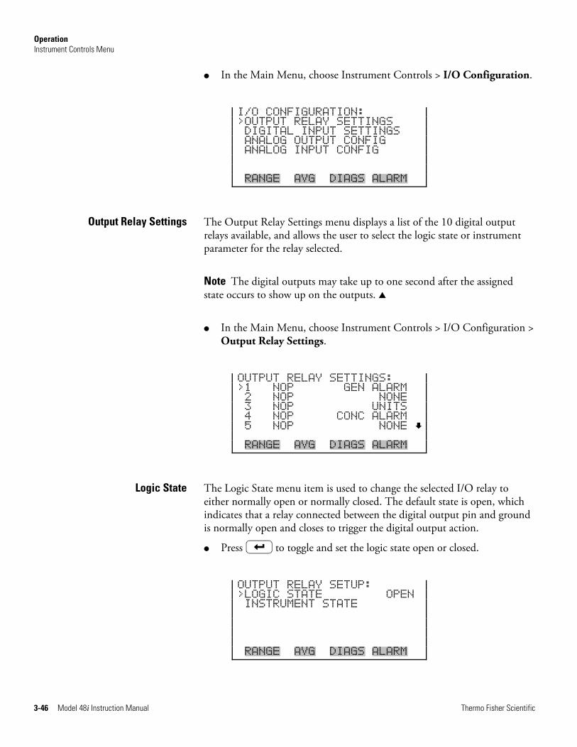
Operation Instrument Controls Menu
3-46 Model 48i Instruction Manual Thermo Fisher Scientific
● In the Main Menu, choose Instrument Controls > I/O Configuration.
I/O CONFIGURATION: >OUTPUT RELAY SETTINGS DIGITAL INPUT SETTINGS ANALOG OUTPUT CONFIG ANALOG INPUT CONFIG RANGE AVG DIAGS ALARM
The Output Relay Settings menu displays a list of the 10 digital output relays available, and allows the user to select the logic state or instrument parameter for the relay selected.
Note The digital outputs may take up to one second after the assigned state occurs to show up on the outputs. ▲
● In the Main Menu, choose Instrument Controls > I/O Configuration > Output Relay Settings.
OUTPUT RELAY SETTINGS: >1 NOP GEN ALARM 2 NOP NONE 3 NOP UNITS 4 NOP CONC ALARM 5 NOP NONE RANGE AVG DIAGS ALARM
The Logic State menu item is used to change the selected I/O relay to either normally open or normally closed. The default state is open, which indicates that a relay connected between the digital output pin and ground is normally open and closes to trigger the digital output action.
● Press to toggle and set the logic state open or closed.
OUTPUT RELAY SETUP: >LOGIC STATE OPEN INSTRUMENT STATE RANGE AVG DIAGS ALARM
Output Relay Settings
Logic State
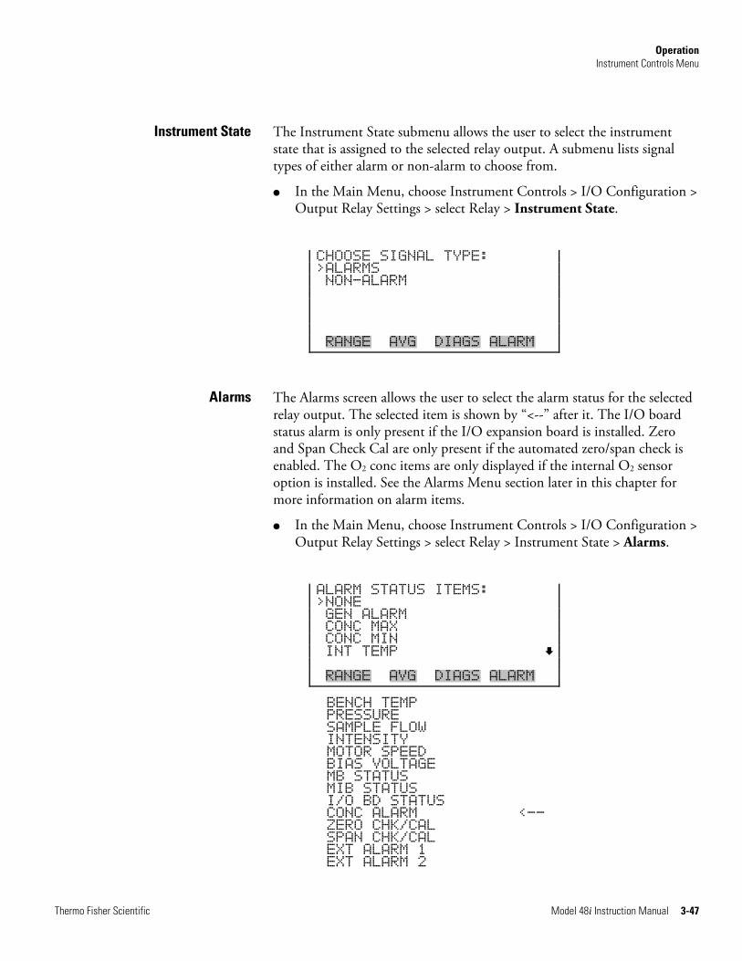
Operation Instrument Controls Menu
Thermo Fisher Scientific Model 48i Instruction Manual 3-47
The Instrument State submenu allows the user to select the instrument state that is assigned to the selected relay output. A submenu lists signal types of either alarm or non-alarm to choose from.
● In the Main Menu, choose Instrument Controls > I/O Configuration > Output Relay Settings > select Relay > Instrument State.
CHOOSE SIGNAL TYPE: >ALARMS NON-ALARM RANGE AVG DIAGS ALARM
The Alarms screen allows the user to select the alarm status for the selected relay output. The selected item is shown by “<--” after it. The I/O board status alarm is only present if the I/O expansion board is installed. Zero and Span Check Cal are only present if the automated zero/span check is enabled. The O2 conc items are only displayed if the internal O2 sensor option is installed. See the Alarms Menu section later in this chapter for more information on alarm items.
● In the Main Menu, choose Instrument Controls > I/O Configuration > Output Relay Settings > select Relay > Instrument State > Alarms.
ALARM STATUS ITEMS: >NONE GEN ALARM CONC MAX CONC MIN INT TEMP RANGE AVG DIAGS ALARM
BENCH TEMP PRESSURE SAMPLE FLOW INTENSITY MOTOR SPEED BIAS VOLTAGE MB STATUS MIB STATUS I/O BD STATUS CONC ALARM <-- ZERO CHK/CAL SPAN CHK/CAL EXT ALARM 1 EXT ALARM 2
Instrument State
Alarms
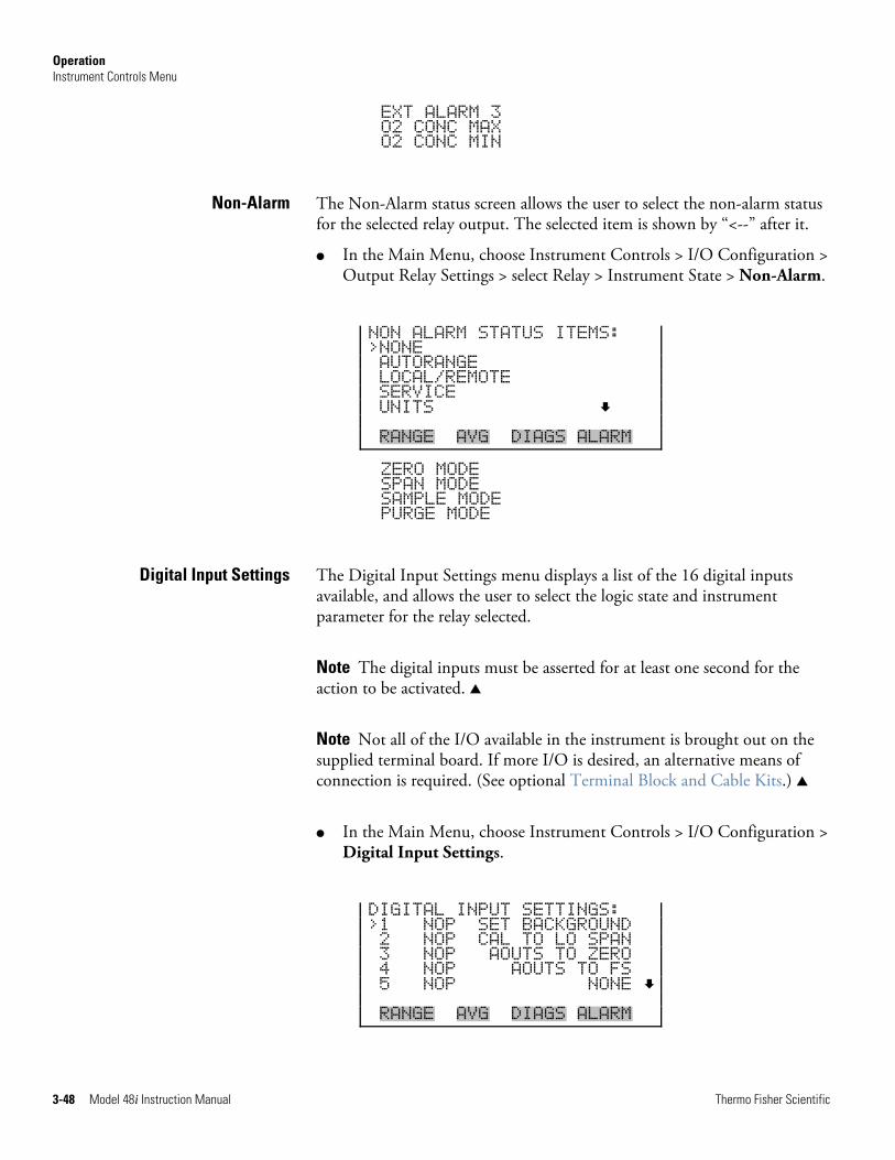
Operation Instrument Controls Menu
3-48 Model 48i Instruction Manual Thermo Fisher Scientific
EXT ALARM 3 O2 CONC MAX O2 CONC MIN
The Non-Alarm status screen allows the user to select the non-alarm status for the selected relay output. The selected item is shown by “<--” after it.
● In the Main Menu, choose Instrument Controls > I/O Configuration > Output Relay Settings > select Relay > Instrument State > Non-Alarm.
NON ALARM STATUS ITEMS: >NONE AUTORANGE LOCAL/REMOTE SERVICE UNITS RANGE AVG DIAGS ALARM
ZERO MODE SPAN MODE SAMPLE MODE PURGE MODE
The Digital Input Settings menu displays a list of the 16 digital inputs available, and allows the user to select the logic state and instrument parameter for the relay selected.
Note The digital inputs must be asserted for at least one second for the action to be activated. ▲
Note Not all of the I/O available in the instrument is brought out on the supplied terminal board. If more I/O is desired, an alternative means of connection is required. (See optional Terminal Block and Cable Kits.) ▲
● In the Main Menu, choose Instrument Controls > I/O Configuration > Digital Input Settings.
DIGITAL INPUT SETTINGS: >1 NOP SET BACKGROUND 2 NOP CAL TO LO SPAN 3 NOP AOUTS TO ZERO 4 NOP AOUTS TO FS 5 NOP NONE RANGE AVG DIAGS ALARM
Non-Alarm
Digital Input Settings
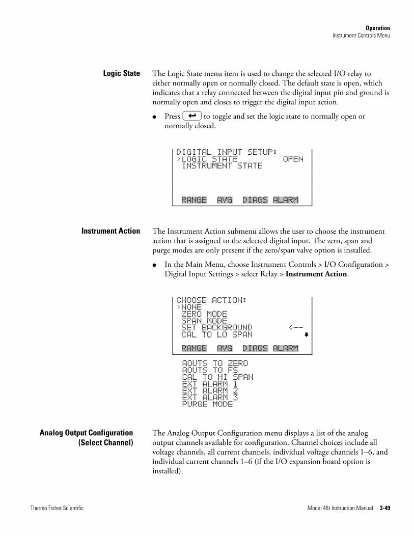
Operation Instrument Controls Menu
Thermo Fisher Scientific Model 48i Instruction Manual 3-49
The Logic State menu item is used to change the selected I/O relay to either normally open or normally closed. The default state is open, which indicates that a relay connected between the digital input pin and ground is normally open and closes to trigger the digital input action.
● Press to toggle and set the logic state to normally open or normally closed.
DIGITAL INPUT SETUP: >LOGIC STATE OPEN INSTRUMENT STATE RANGE AVG DIAGS ALARM
The Instrument Action submenu allows the user to choose the instrument action that is assigned to the selected digital input. The zero, span and purge modes are only present if the zero/span valve option is installed.
● In the Main Menu, choose Instrument Controls > I/O Configuration > Digital Input Settings > select Relay > Instrument Action.
CHOOSE ACTION: >NONE ZERO MODE SPAN MODE SET BACKGROUND <-- CAL TO LO SPAN RANGE AVG DIAGS ALARM
AOUTS TO ZERO AOUTS TO FS CAL TO HI SPAN EXT ALARM 1 EXT ALARM 2 EXT ALARM 3 PURGE MODE
The Analog Output Configuration menu displays a list of the analog output channels available for configuration. Channel choices include all voltage channels, all current channels, individual voltage channels 1–6, and individual current channels 1–6 (if the I/O expansion board option is installed).
Logic State
Instrument Action
Analog Output Configuration (Select Channel)
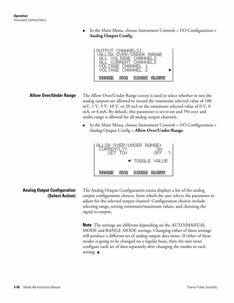
Operation Instrument Controls Menu
3-50 Model 48i Instruction Manual Thermo Fisher Scientific
● In the Main Menu, choose Instrument Controls > I/O Configuration > Analog Output Config.
OUTPUT CHANNELS: >ALLOW OVER/UNDER RANGE ALL VOLTAGE CHANNELS ALL CURRENT CHANNELS VOLTAGE CHANNEL 1 VOLTAGE CHANNEL 2 RANGE AVG DIAGS ALARM
The Allow Over/Under Range screen is used to select whether or not the analog outputs are allowed to exceed the maximum selected value of 100 mV, 1 V, 5 V, 10 V, or 20 mA or the minimum selected value of 0 V, 0 mA, or 4 mA. By default, this parameter is set to on and 5% over and under range is allowed for all analog output channels.
● In the Main Menu, choose Instrument Controls > I/O Configuration > Analog Output Config > Allow Over/Under Range.
ALLOW OVER/UNDER RANGE: CURRENTLY: ON SET TO: OFF ? TOGGLE VALUE RANGE AVG DIAGS ALARM
The Analog Output Configuration menu displays a list of the analog output configuration choices, from which the user selects the parameter to adjust for the selected output channel. Configuration choices include selecting range, setting minimum/maximum values, and choosing the signal to output.
Note The settings are different depending on the AUTO/MANUAL MODE and RANGE MODE settings. Changing either of these settings will produce a different set of analog output data items. If either of these modes is going to be changed on a regular basis, then the user must configure each set of data separately after changing the modes to each setting. ▲
Allow Over/Under Range
Analog Output Configuration(Select Action)
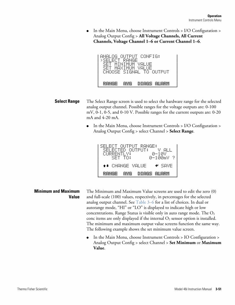
Operation Instrument Controls Menu
Thermo Fisher Scientific Model 48i Instruction Manual 3-51
● In the Main Menu, choose Instrument Controls > I/O Configuration > Analog Output Config > All Voltage Channels, All Current Channels, Voltage Channel 1–6 or Current Channel 1–6.
ANALOG OUTPUT CONFIG: >SELECT RANGE SET MINIMUM VALUE SET MAXIMUM VALUE CHOOSE SIGNAL TO OUTPUT RANGE AVG DIAGS ALARM
The Select Range screen is used to select the hardware range for the selected analog output channel. Possible ranges for the voltage outputs are: 0-100 mV, 0-1, 0-5, and 0-10 V. Possible ranges for the current outputs are: 0-20 mA and 4-20 mA.
● In the Main Menu, choose Instrument Controls > I/O Configuration > Analog Output Config > select Channel > Select Range.
SELECT OUTPUT RANGE: SELECTED OUTPUT: V ALL CURRENTLY: 0-10V SET TO: 0-100mV ? CHANGE VALUE SAVE RANGE AVG DIAGS ALARM
The Minimum and Maximum Value screens are used to edit the zero (0) and full-scale (100) values, respectively, in percentages for the selected analog output channel. See Table 3–6 for a list of choices. In dual or autorange mode, “HI” or “LO” is displayed to indicate high or low concentrations. Range Status is visible only in auto range mode. The O2 conc items are only displayed if the internal O2 sensor option is installed. The minimum and maximum output value screens function the same way. The following example shows the set minimum value screen.
● In the Main Menu, choose Instrument Controls > IO Configuration > Analog Output Config > select Channel > Set Minimum or Maximum Value.
Select Range
Minimum and Maximum Value
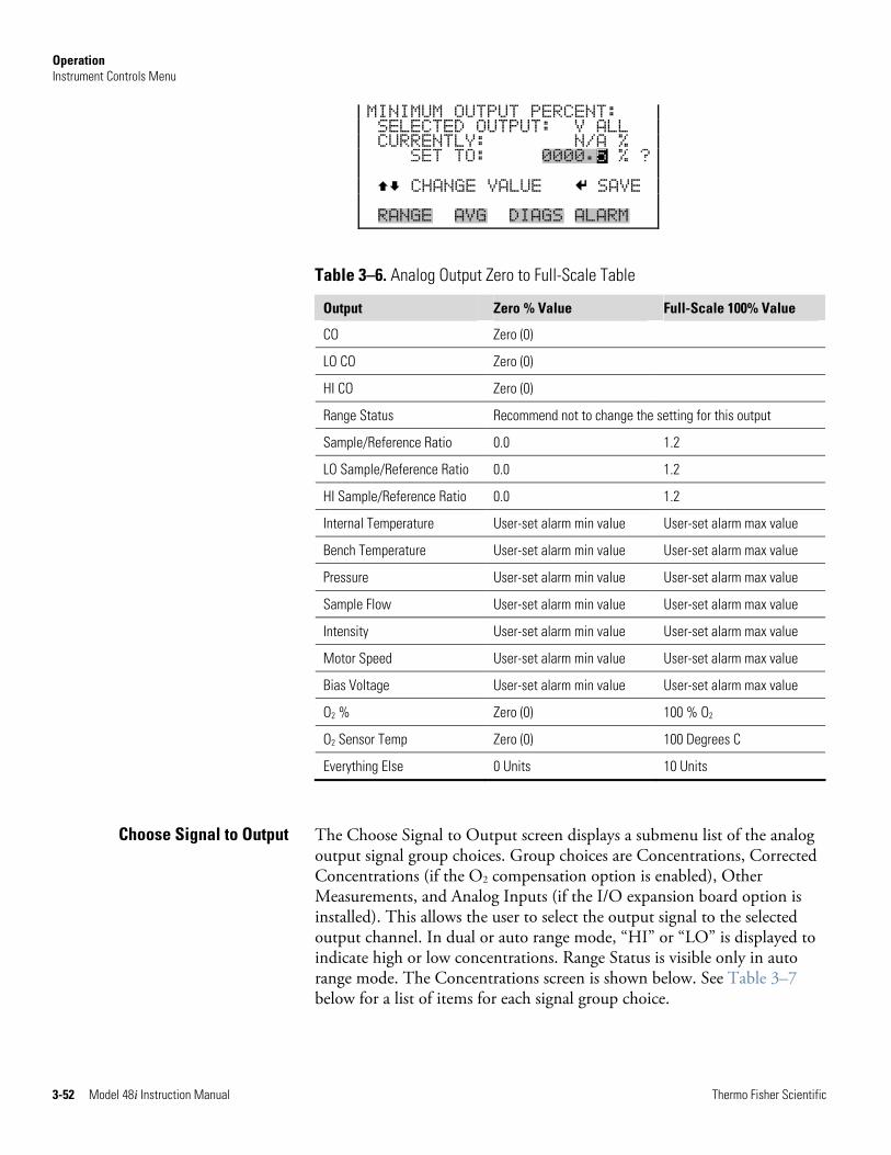
Operation Instrument Controls Menu
3-52 Model 48i Instruction Manual Thermo Fisher Scientific
MINIMUM OUTPUT PERCENT: SELECTED OUTPUT: V ALL CURRENTLY: N/A % SET TO: 0000.5 % ? CHANGE VALUE SAVE RANGE AVG DIAGS ALARM
Table 3–6. Analog Output Zero to Full-Scale Table
Output Zero % Value Full-Scale 100% Value
CO Zero (0)
LO CO Zero (0)
HI CO Zero (0)
Range Status Recommend not to change the setting for this output
Sample/Reference Ratio 0.0 1.2
LO Sample/Reference Ratio 0.0 1.2
HI Sample/Reference Ratio 0.0 1.2
Internal Temperature User-set alarm min value User-set alarm max value
Bench Temperature User-set alarm min value User-set alarm max value
Pressure User-set alarm min value User-set alarm max value
Sample Flow User-set alarm min value User-set alarm max value
Intensity User-set alarm min value User-set alarm max value
Motor Speed User-set alarm min value User-set alarm max value
Bias Voltage User-set alarm min value User-set alarm max value
O2 % Zero (0) 100 % O2
O2 Sensor Temp Zero (0) 100 Degrees C
Everything Else 0 Units 10 Units
The Choose Signal to Output screen displays a submenu list of the analog output signal group choices. Group choices are Concentrations, Corrected Concentrations (if the O2 compensation option is enabled), Other Measurements, and Analog Inputs (if the I/O expansion board option is installed). This allows the user to select the output signal to the selected output channel. In dual or auto range mode, “HI” or “LO” is displayed to indicate high or low concentrations. Range Status is visible only in auto range mode. The Concentrations screen is shown below. See Table 3–7 below for a list of items for each signal group choice.
Choose Signal to Output
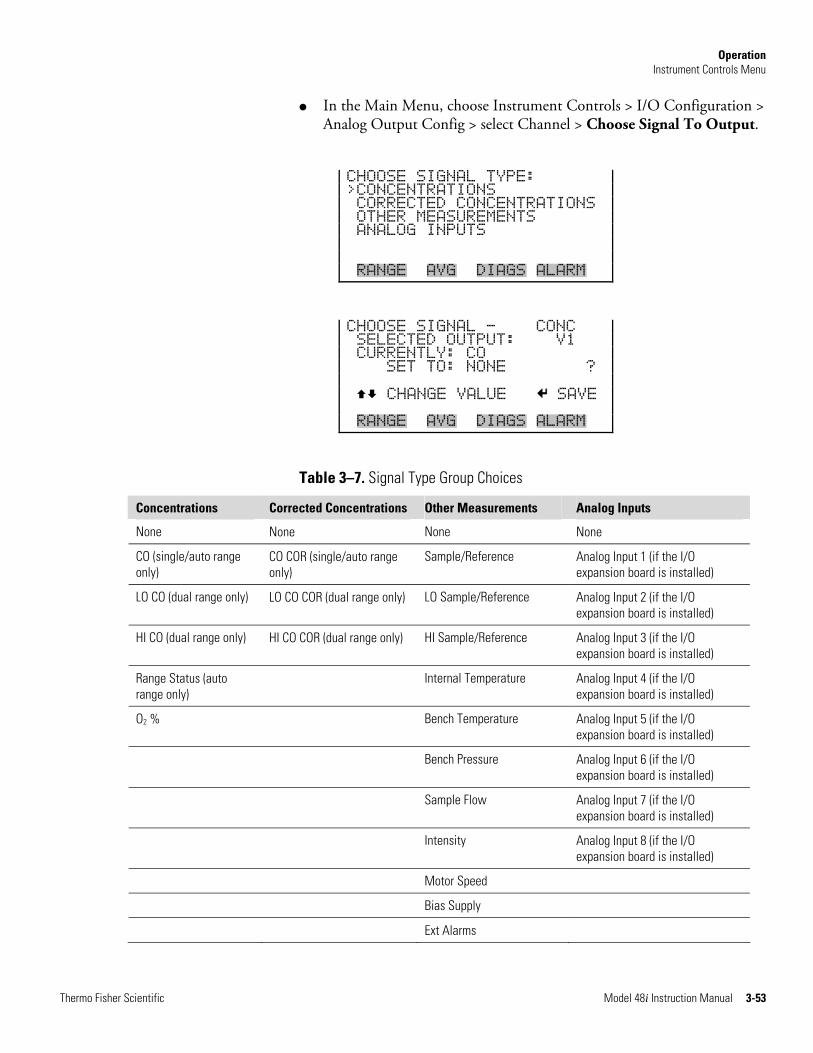
Operation Instrument Controls Menu
Thermo Fisher Scientific Model 48i Instruction Manual 3-53
● In the Main Menu, choose Instrument Controls > I/O Configuration > Analog Output Config > select Channel > Choose Signal To Output.
CHOOSE SIGNAL TYPE: >CONCENTRATIONS CORRECTED CONCENTRATIONS OTHER MEASUREMENTS ANALOG INPUTS RANGE AVG DIAGS ALARM
CHOOSE SIGNAL - CONC SELECTED OUTPUT: V1 CURRENTLY: CO SET TO: NONE ? CHANGE VALUE SAVE RANGE AVG DIAGS ALARM
Table 3–7. Signal Type Group Choices
Concentrations Corrected Concentrations Other Measurements Analog Inputs
None None None None
CO (single/auto range only)
CO COR (single/auto range only)
Sample/Reference Analog Input 1 (if the I/O expansion board is installed)
LO CO (dual range only) LO CO COR (dual range only) LO Sample/Reference Analog Input 2 (if the I/O expansion board is installed)
HI CO (dual range only) HI CO COR (dual range only) HI Sample/Reference Analog Input 3 (if the I/O expansion board is installed)
Range Status (auto range only)
Internal Temperature Analog Input 4 (if the I/O expansion board is installed)
O2 % Bench Temperature Analog Input 5 (if the I/O expansion board is installed)
Bench Pressure Analog Input 6 (if the I/O expansion board is installed)
Sample Flow Analog Input 7 (if the I/O expansion board is installed)
Intensity Analog Input 8 (if the I/O expansion board is installed)
Motor Speed
Bias Supply
Ext Alarms
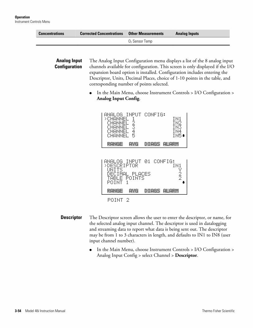
Operation Instrument Controls Menu
3-54 Model 48i Instruction Manual Thermo Fisher Scientific
Concentrations Corrected Concentrations Other Measurements Analog Inputs
O2 Sensor Temp
The Analog Input Configuration menu displays a list of the 8 analog input channels available for configuration. This screen is only displayed if the I/O expansion board option is installed. Configuration includes entering the Descriptor, Units, Decimal Places, choice of 1-10 points in the table, and corresponding number of points selected.
● In the Main Menu, choose Instrument Controls > I/O Configuration > Analog Input Config.
ANALOG INPUT CONFIG: >CHANNEL 1 IN1 CHANNEL 2 IN2 CHANNEL 3 IN3 CHANNEL 4 IN4 CHANNEL 5 IN5 RANGE AVG DIAGS ALARM
ANALOG INPUT 01 CONFIG: >DESCRIPTOR IN1 UNITS V DECIMAL PLACES 2 TABLE POINTS 2 POINT 1 RANGE AVG DIAGS ALARM
POINT 2
The Descriptor screen allows the user to enter the descriptor, or name, for the selected analog input channel. The descriptor is used in datalogging and streaming data to report what data is being sent out. The descriptor may be from 1 to 3 characters in length, and defaults to IN1 to IN8 (user input channel number).
● In the Main Menu, choose Instrument Controls > I/O Configuration > Analog Input Config > select Channel > Descriptor.
Analog Input Configuration
Descriptor
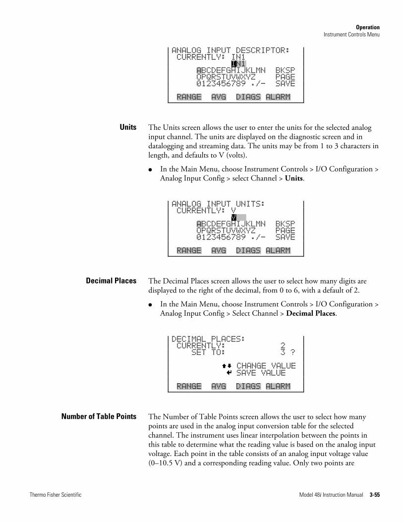
Operation Instrument Controls Menu
Thermo Fisher Scientific Model 48i Instruction Manual 3-55
ANALOG INPUT DESCRIPTOR: CURRENTLY: IN1 IN1 ABCDEFGHIJKLMN BKSP OPQRSTUVWXYZ PAGE 0123456789 ./- SAVE RANGE AVG DIAGS ALARM
The Units screen allows the user to enter the units for the selected analog input channel. The units are displayed on the diagnostic screen and in datalogging and streaming data. The units may be from 1 to 3 characters in length, and defaults to V (volts).
● In the Main Menu, choose Instrument Controls > I/O Configuration > Analog Input Config > select Channel > Units.
ANALOG INPUT UNITS: CURRENTLY: V VN1 ABCDEFGHIJKLMN BKSP OPQRSTUVWXYZ PAGE 0123456789 ./- SAVE RANGE AVG DIAGS ALARM
The Decimal Places screen allows the user to select how many digits are displayed to the right of the decimal, from 0 to 6, with a default of 2.
● In the Main Menu, choose Instrument Controls > I/O Configuration > Analog Input Config > Select Channel > Decimal Places.
DECIMAL PLACES: CURRENTLY: 2 SET TO: 3 ? CHANGE VALUE SAVE VALUE RANGE AVG DIAGS ALARM
The Number of Table Points screen allows the user to select how many points are used in the analog input conversion table for the selected channel. The instrument uses linear interpolation between the points in this table to determine what the reading value is based on the analog input voltage. Each point in the table consists of an analog input voltage value (0–10.5 V) and a corresponding reading value. Only two points are
Units
Decimal Places
Number of Table Points
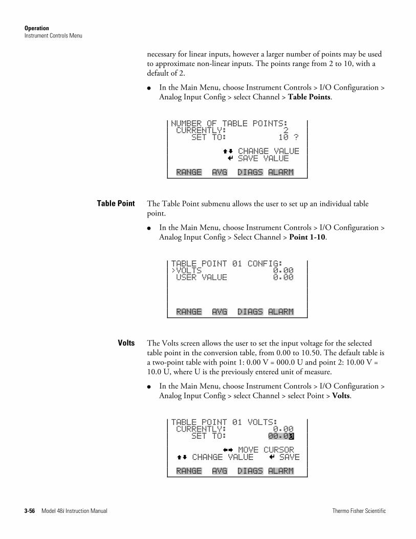
Operation Instrument Controls Menu
3-56 Model 48i Instruction Manual Thermo Fisher Scientific
necessary for linear inputs, however a larger number of points may be used to approximate non-linear inputs. The points range from 2 to 10, with a default of 2.
● In the Main Menu, choose Instrument Controls > I/O Configuration > Analog Input Config > select Channel > Table Points.
NUMBER OF TABLE POINTS: CURRENTLY: 2 SET TO: 10 ? CHANGE VALUE SAVE VALUE RANGE AVG DIAGS ALARM
The Table Point submenu allows the user to set up an individual table point.
● In the Main Menu, choose Instrument Controls > I/O Configuration > Analog Input Config > Select Channel > Point 1-10.
TABLE POINT 01 CONFIG: >VOLTS 0.00 USER VALUE 0.00 RANGE AVG DIAGS ALARM
The Volts screen allows the user to set the input voltage for the selected table point in the conversion table, from 0.00 to 10.50. The default table is a two-point table with point 1: 0.00 V = 000.0 U and point 2: 10.00 V = 10.0 U, where U is the previously entered unit of measure.
● In the Main Menu, choose Instrument Controls > I/O Configuration > Analog Input Config > select Channel > select Point > Volts.
TABLE POINT 01 VOLTS: CURRENTLY: 0.00 SET TO: 00.00 MOVE CURSOR CHANGE VALUE SAVE RANGE AVG DIAGS ALARM
Table Point
Volts
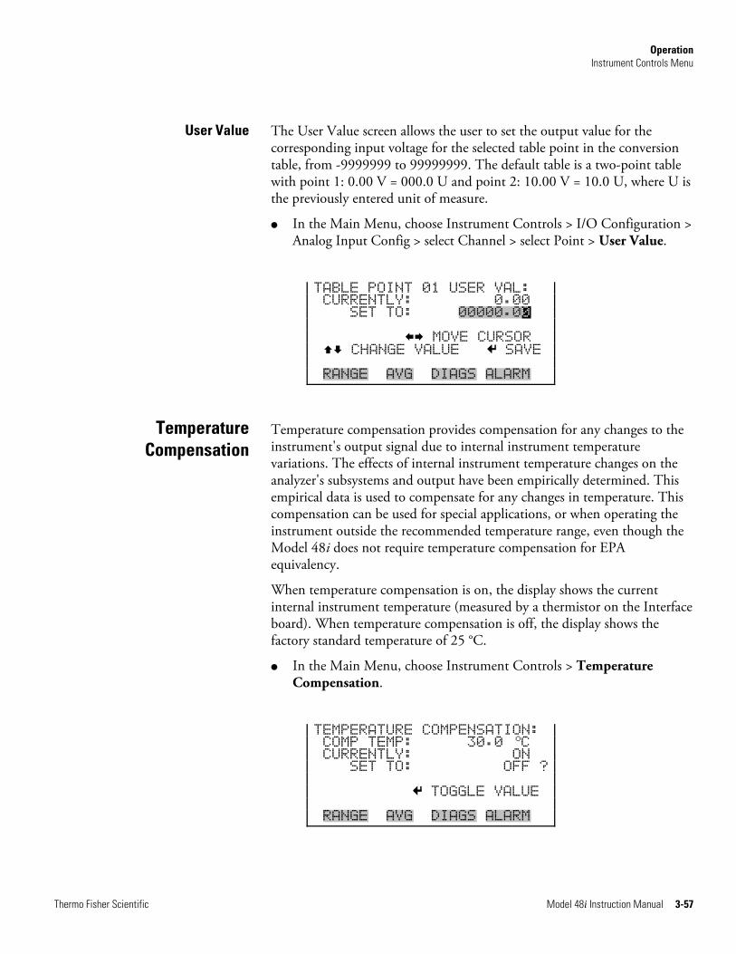
Operation Instrument Controls Menu
Thermo Fisher Scientific Model 48i Instruction Manual 3-57
The User Value screen allows the user to set the output value for the corresponding input voltage for the selected table point in the conversion table, from -9999999 to 99999999. The default table is a two-point table with point 1: 0.00 V = 000.0 U and point 2: 10.00 V = 10.0 U, where U is the previously entered unit of measure.
● In the Main Menu, choose Instrument Controls > I/O Configuration > Analog Input Config > select Channel > select Point > User Value.
TABLE POINT 01 USER VAL: CURRENTLY: 0.00 SET TO: 00000.00 MOVE CURSOR CHANGE VALUE SAVE RANGE AVG DIAGS ALARM
Temperature compensation provides compensation for any changes to the instrument's output signal due to internal instrument temperature variations. The effects of internal instrument temperature changes on the analyzer's subsystems and output have been empirically determined. This empirical data is used to compensate for any changes in temperature. This compensation can be used for special applications, or when operating the instrument outside the recommended temperature range, even though the Model 48i does not require temperature compensation for EPA equivalency.
When temperature compensation is on, the display shows the current internal instrument temperature (measured by a thermistor on the Interface board). When temperature compensation is off, the display shows the factory standard temperature of 25 °C.
● In the Main Menu, choose Instrument Controls > Temperature Compensation.
TEMPERATURE COMPENSATION: COMP TEMP: 30.0
oC CURRENTLY: ON SET TO: OFF ? TOGGLE VALUE RANGE AVG DIAGS ALARM
User Value
Temperature Compensation
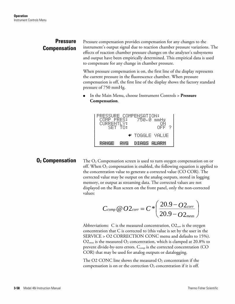
Operation Instrument Controls Menu
3-58 Model 48i Instruction Manual Thermo Fisher Scientific
Pressure compensation provides compensation for any changes to the instrument's output signal due to reaction chamber pressure variations. The effects of reaction chamber pressure changes on the analyzer's subsystems and output have been empirically determined. This empirical data is used to compensate for any change in chamber pressure.
When pressure compensation is on, the first line of the display represents the current pressure in the fluorescence chamber. When pressure compensation is off, the first line of the display shows the factory standard pressure of 750 mmHg.
● In the Main Menu, choose Instrument Controls > Pressure Compensation.
PRESSURE COMPENSATION: COMP PRES: 750.0 mmHg CURRENTLY: ON SET TO: OFF ? TOGGLE VALUE RANGE AVG DIAGS ALARM
The O2 Compensation screen is used to turn oxygen compensation on or off. When O2 compensation is enabled, the following equation is applied to the concentration value to generate a corrected value (CO COR). The corrected value may be output on the analog outputs, stored in logging memory, or output as streaming data. The corrected values are not displayed on the Run screen on the front panel, only the non-corrected values:
⎟⎠⎞
⎜⎝⎛
−−
=29.2029.20*2@
OOCOC
meas
corrcorrcomp
Abbreviations: C is the measured concentration, O2corr is the oxygen concentration that C is corrected to (this value is set by the user in the SERVICE > O2 CORRECTION CONC menu and defaults to 15%). O2meas is the measured O2 concentration, which is clamped at 20.8% to prevent divide-by-zero errors. Ccomp is the corrected concentration (CO COR) that may be used for analog outputs or datalogging.
The O2 CONC line shows the measured O2 concentration if the compensation is on or the correction O2 concentration if it is off.
Pressure Compensation
O2 Compensation
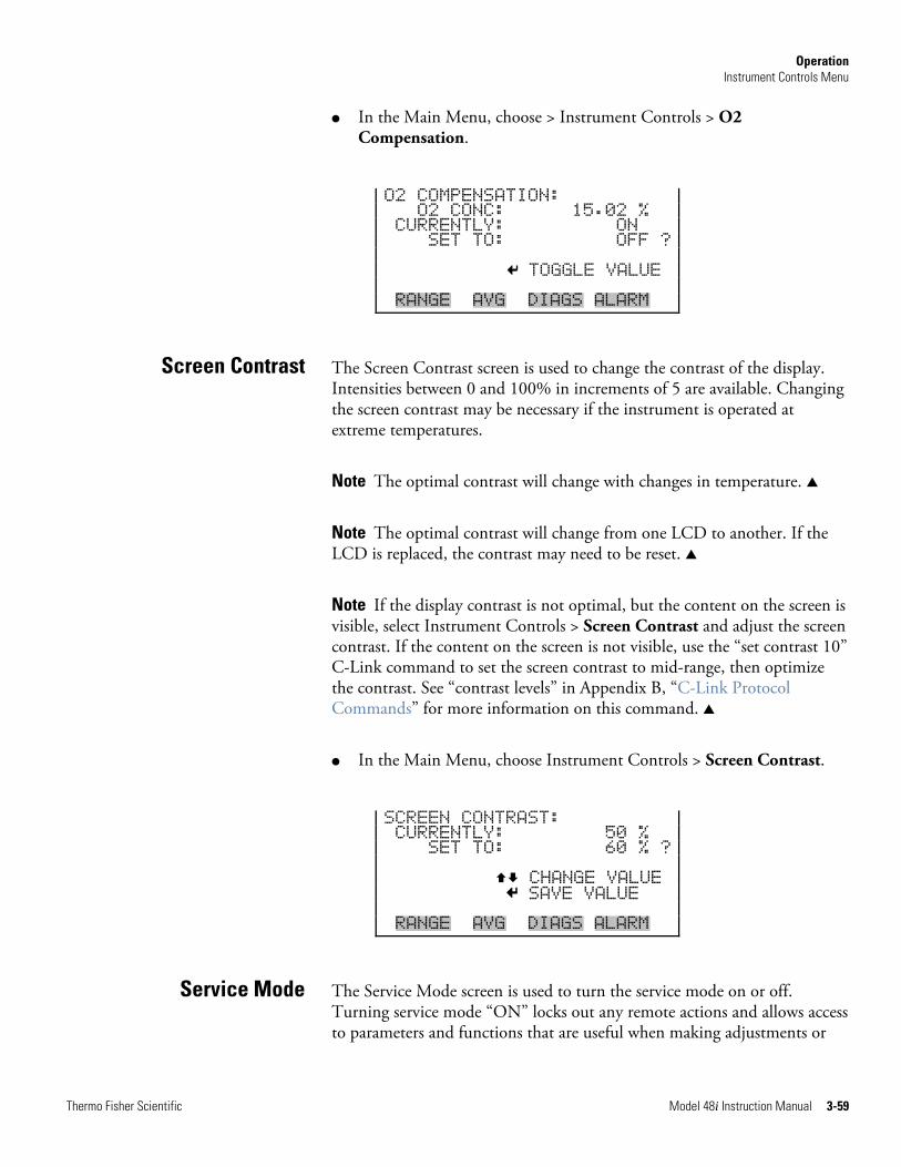
Operation Instrument Controls Menu
Thermo Fisher Scientific Model 48i Instruction Manual 3-59
● In the Main Menu, choose > Instrument Controls > O2 Compensation.
O2 COMPENSATION: O2 CONC: 15.02 % CURRENTLY: ON SET TO: OFF ? TOGGLE VALUE RANGE AVG DIAGS ALARM
The Screen Contrast screen is used to change the contrast of the display. Intensities between 0 and 100% in increments of 5 are available. Changing the screen contrast may be necessary if the instrument is operated at extreme temperatures.
Note The optimal contrast will change with changes in temperature. ▲
Note The optimal contrast will change from one LCD to another. If the LCD is replaced, the contrast may need to be reset. ▲
Note If the display contrast is not optimal, but the content on the screen is visible, select Instrument Controls > Screen Contrast and adjust the screen contrast. If the content on the screen is not visible, use the “set contrast 10” C-Link command to set the screen contrast to mid-range, then optimize the contrast. See “contrast levels” in Appendix B, “C-Link Protocol Commands” for more information on this command. ▲
● In the Main Menu, choose Instrument Controls > Screen Contrast.
SCREEN CONTRAST: CURRENTLY: 50 % SET TO: 60 % ? CHANGE VALUE SAVE VALUE RANGE AVG DIAGS ALARM
The Service Mode screen is used to turn the service mode on or off. Turning service mode “ON” locks out any remote actions and allows access to parameters and functions that are useful when making adjustments or
Screen Contrast
Service Mode
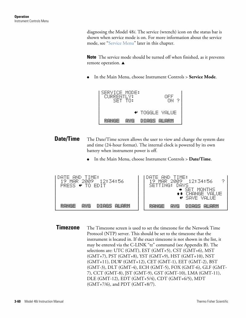
Operation Instrument Controls Menu
3-60 Model 48i Instruction Manual Thermo Fisher Scientific
diagnosing the Model 48i. The service (wrench) icon on the status bar is shown when service mode is on. For more information about the service mode, see “Service Menu” later in this chapter.
Note The service mode should be turned off when finished, as it prevents remote operation. ▲
● In the Main Menu, choose Instrument Controls > Service Mode.
SERVICE MODE: CURRENTLY: OFF SET TO: ON ? TOGGLE VALUE RANGE AVG DIAGS ALARM
The Date/Time screen allows the user to view and change the system date and time (24-hour format). The internal clock is powered by its own battery when instrument power is off.
● In the Main Menu, choose Instrument Controls > Date/Time.
The Timezone screen is used to set the timezone for the Network Time Protocol (NTP) server. This should be set to the timezone that the instrument is located in. If the exact timezone is not shown in the list, it may be entered via the C-LINK “tz” command (see Appendix B). The selections are: UTC (GMT), EST (GMT+5), CST (GMT+6), MST (GMT+7), PST (GMT+8), YST (GMT+9), HST (GMT+10), NST (GMT+11), DLW (GMT+12), CET (GMT-1), EET (GMT-2), BST (GMT-3), DLT (GMT-4), ECH (GMT-5), FOX (GMT-6), GLF (GMT-7), CCT (GMT-8), JST (GMT-9), GST (GMT-10), LMA (GMT-11), DLE (GMT-12), EDT (GMT+5/4), CDT (GMT+6/5), MDT (GMT+7/6), and PDT (GMT+8/7).
Date/Time
Timezone
DATE AND TIME: 19 MAR 2009 12:34:56 PRESS TO EDIT RANGE AVG DIAGS ALARM
DATE AND TIME: 19 MAR 2009 12:34:56 ? SETTING: DAYS SET MONTHS CHANGE VALUE SAVE VALUE RANGE AVG DIAGS ALARM
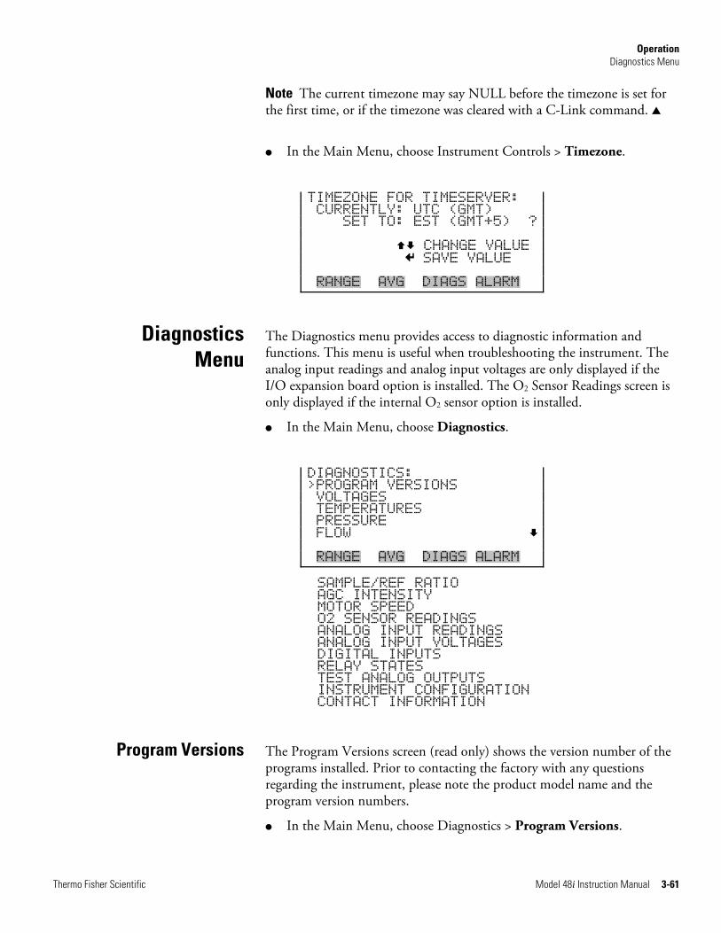
Operation Diagnostics Menu
Thermo Fisher Scientific Model 48i Instruction Manual 3-61
Note The current timezone may say NULL before the timezone is set for the first time, or if the timezone was cleared with a C-Link command. ▲
● In the Main Menu, choose Instrument Controls > Timezone.
TIMEZONE FOR TIMESERVER: CURRENTLY: UTC (GMT) SET TO: EST (GMT+5) ? CHANGE VALUE SAVE VALUE RANGE AVG DIAGS ALARM
The Diagnostics menu provides access to diagnostic information and functions. This menu is useful when troubleshooting the instrument. The analog input readings and analog input voltages are only displayed if the I/O expansion board option is installed. The O2 Sensor Readings screen is only displayed if the internal O2 sensor option is installed.
● In the Main Menu, choose Diagnostics.
DIAGNOSTICS: >PROGRAM VERSIONS VOLTAGES TEMPERATURES PRESSURE FLOW RANGE AVG DIAGS ALARM
SAMPLE/REF RATIO AGC INTENSITY MOTOR SPEED O2 SENSOR READINGS ANALOG INPUT READINGS ANALOG INPUT VOLTAGES DIGITAL INPUTS RELAY STATES TEST ANALOG OUTPUTS INSTRUMENT CONFIGURATION CONTACT INFORMATION
The Program Versions screen (read only) shows the version number of the programs installed. Prior to contacting the factory with any questions regarding the instrument, please note the product model name and the program version numbers.
● In the Main Menu, choose Diagnostics > Program Versions.
Diagnostics Menu
Program Versions
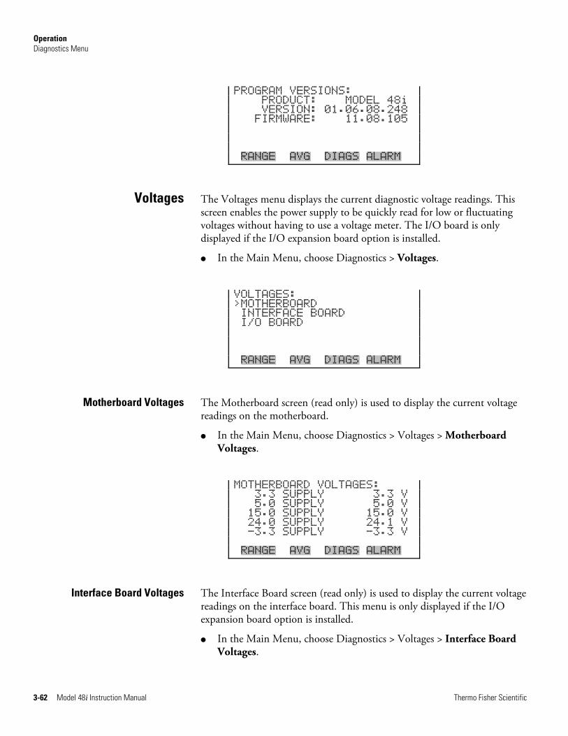
Operation Diagnostics Menu
3-62 Model 48i Instruction Manual Thermo Fisher Scientific
PROGRAM VERSIONS: PRODUCT: MODEL 48i VERSION: 01.06.08.248 FIRMWARE: 11.08.105 RANGE AVG DIAGS ALARM
The Voltages menu displays the current diagnostic voltage readings. This screen enables the power supply to be quickly read for low or fluctuating voltages without having to use a voltage meter. The I/O board is only displayed if the I/O expansion board option is installed.
● In the Main Menu, choose Diagnostics > Voltages.
VOLTAGES: >MOTHERBOARD INTERFACE BOARD I/O BOARD RANGE AVG DIAGS ALARM
The Motherboard screen (read only) is used to display the current voltage readings on the motherboard.
● In the Main Menu, choose Diagnostics > Voltages > Motherboard Voltages.
MOTHERBOARD VOLTAGES: 3.3 SUPPLY 3.3 V 5.0 SUPPLY 5.0 V 15.0 SUPPLY 15.0 V 24.0 SUPPLY 24.1 V -3.3 SUPPLY -3.3 V RANGE AVG DIAGS ALARM
The Interface Board screen (read only) is used to display the current voltage readings on the interface board. This menu is only displayed if the I/O expansion board option is installed.
● In the Main Menu, choose Diagnostics > Voltages > Interface Board Voltages.
Voltages
Motherboard Voltages
Interface Board Voltages
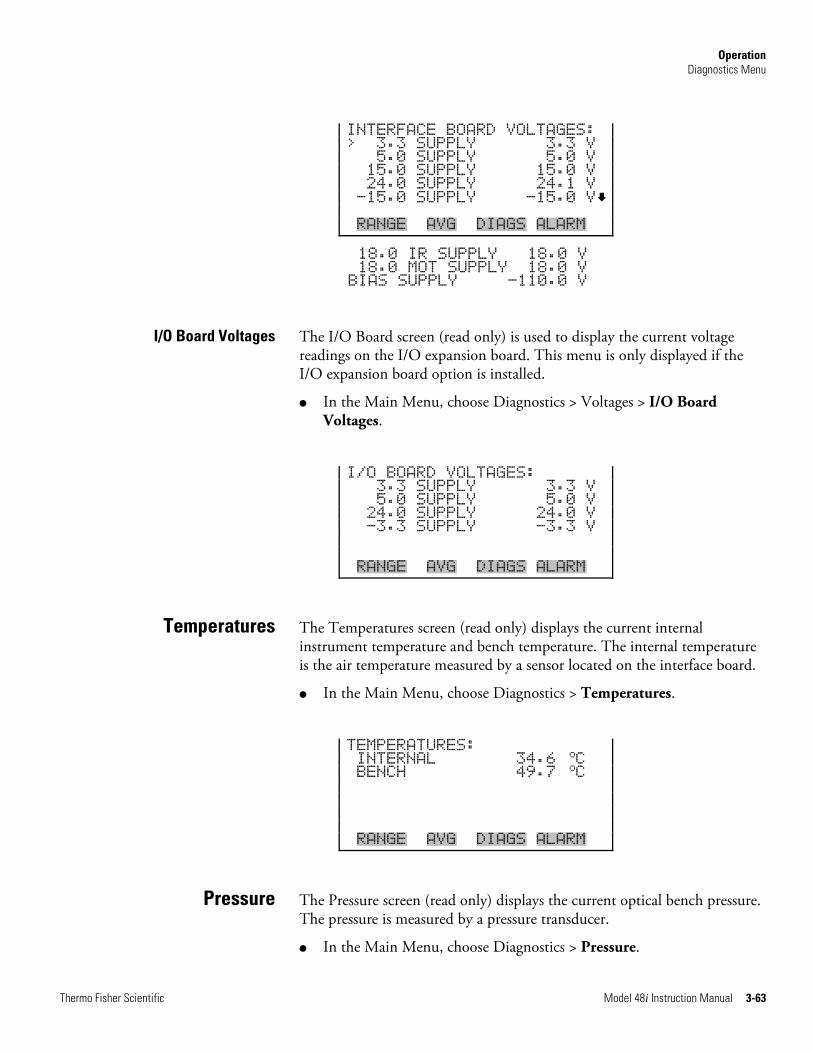
Operation Diagnostics Menu
Thermo Fisher Scientific Model 48i Instruction Manual 3-63
INTERFACE BOARD VOLTAGES: > 3.3 SUPPLY 3.3 V 5.0 SUPPLY 5.0 V 15.0 SUPPLY 15.0 V 24.0 SUPPLY 24.1 V -15.0 SUPPLY -15.0 V RANGE AVG DIAGS ALARM
18.0 IR SUPPLY 18.0 V 18.0 MOT SUPPLY 18.0 V BIAS SUPPLY -110.0 V
The I/O Board screen (read only) is used to display the current voltage readings on the I/O expansion board. This menu is only displayed if the I/O expansion board option is installed.
● In the Main Menu, choose Diagnostics > Voltages > I/O Board Voltages.
I/O BOARD VOLTAGES: 3.3 SUPPLY 3.3 V 5.0 SUPPLY 5.0 V 24.0 SUPPLY 24.0 V -3.3 SUPPLY -3.3 V RANGE AVG DIAGS ALARM
The Temperatures screen (read only) displays the current internal instrument temperature and bench temperature. The internal temperature is the air temperature measured by a sensor located on the interface board.
● In the Main Menu, choose Diagnostics > Temperatures.
TEMPERATURES: INTERNAL 34.6
oC BENCH 49.7
oC RANGE AVG DIAGS ALARM
The Pressure screen (read only) displays the current optical bench pressure. The pressure is measured by a pressure transducer.
● In the Main Menu, choose Diagnostics > Pressure.
I/O Board Voltages
Temperatures
Pressure
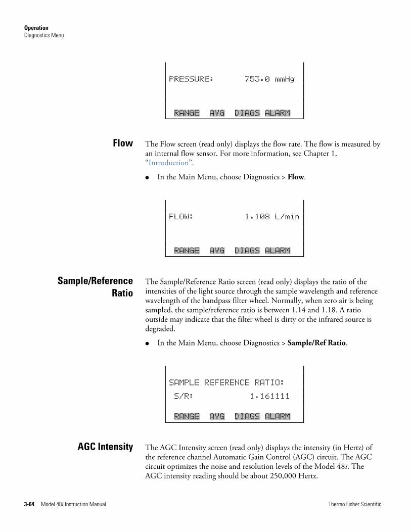
Operation Diagnostics Menu
3-64 Model 48i Instruction Manual Thermo Fisher Scientific
PRESSURE: 753.0 mmHg RANGE AVG DIAGS ALARM
The Flow screen (read only) displays the flow rate. The flow is measured by an internal flow sensor. For more information, see Chapter 1, “Introduction”.
● In the Main Menu, choose Diagnostics > Flow.
FLOW: 1.108 L/min RANGE AVG DIAGS ALARM
The Sample/Reference Ratio screen (read only) displays the ratio of the intensities of the light source through the sample wavelength and reference wavelength of the bandpass filter wheel. Normally, when zero air is being sampled, the sample/reference ratio is between 1.14 and 1.18. A ratio outside may indicate that the filter wheel is dirty or the infrared source is degraded.
● In the Main Menu, choose Diagnostics > Sample/Ref Ratio.
SAMPLE REFERENCE RATIO: S/R: 1.161111 RANGE AVG DIAGS ALARM
The AGC Intensity screen (read only) displays the intensity (in Hertz) of the reference channel Automatic Gain Control (AGC) circuit. The AGC circuit optimizes the noise and resolution levels of the Model 48i. The AGC intensity reading should be about 250,000 Hertz.
Flow
Sample/Reference Ratio
AGC Intensity
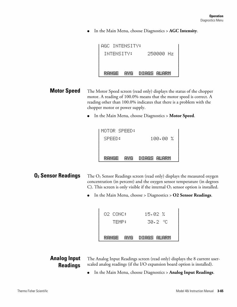
Operation Diagnostics Menu
Thermo Fisher Scientific Model 48i Instruction Manual 3-65
● In the Main Menu, choose Diagnostics > AGC Intensity.
AGC INTENSITY: INTENSITY: 250000 Hz RANGE AVG DIAGS ALARM
The Motor Speed screen (read only) displays the status of the chopper motor. A reading of 100.0% means that the motor speed is correct. A reading other than 100.0% indicates that there is a problem with the chopper motor or power supply.
● In the Main Menu, choose Diagnostics > Motor Speed.
MOTOR SPEED: SPEED: 100.00 % RANGE AVG DIAGS ALARM
The O2 Sensor Readings screen (read only) displays the measured oxygen concentration (in percent) and the oxygen sensor temperature (in degrees C). This screen is only visible if the internal O2 sensor option is installed.
● In the Main Menu, choose > Diagnostics > O2 Sensor Readings.
O2 CONC: 15.02 % TEMP: 30.2
oC RANGE AVG DIAGS ALARM
The Analog Input Readings screen (read only) displays the 8 current user-scaled analog readings (if the I/O expansion board option is installed).
● In the Main Menu, choose Diagnostics > Analog Input Readings.
Motor Speed
O2 Sensor Readings
Analog Input Readings
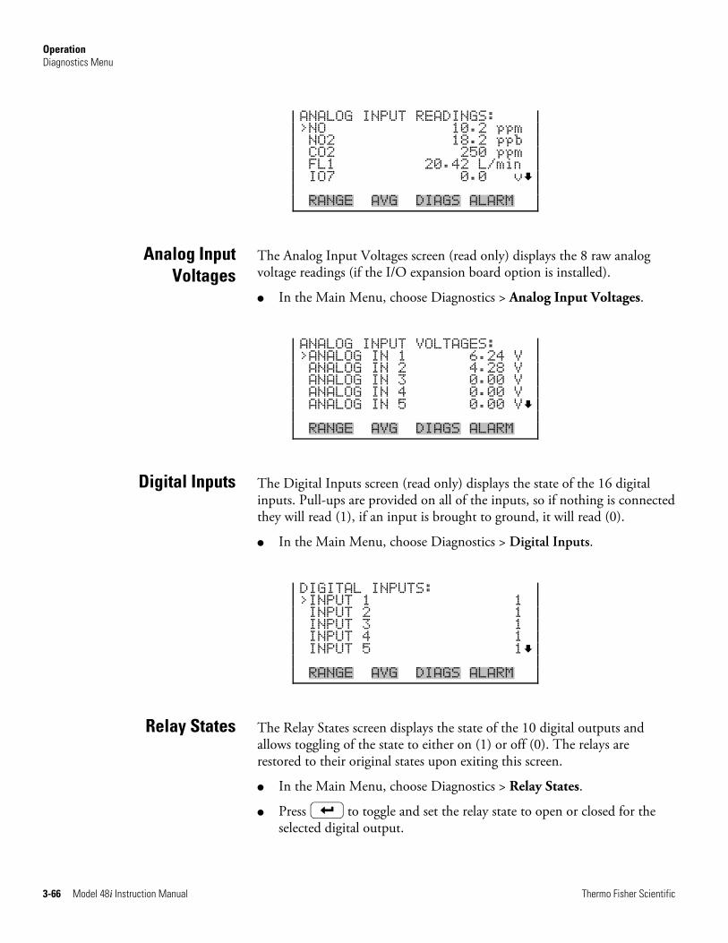
Operation Diagnostics Menu
3-66 Model 48i Instruction Manual Thermo Fisher Scientific
ANALOG INPUT READINGS: >NO 10.2 ppm NO2 18.2 ppb CO2 250 ppm FL1 20.42 L/min IO7 0.0 v RANGE AVG DIAGS ALARM
The Analog Input Voltages screen (read only) displays the 8 raw analog voltage readings (if the I/O expansion board option is installed).
● In the Main Menu, choose Diagnostics > Analog Input Voltages.
ANALOG INPUT VOLTAGES: >ANALOG IN 1 6.24 V ANALOG IN 2 4.28 V ANALOG IN 3 0.00 V ANALOG IN 4 0.00 V ANALOG IN 5 0.00 V RANGE AVG DIAGS ALARM
The Digital Inputs screen (read only) displays the state of the 16 digital inputs. Pull-ups are provided on all of the inputs, so if nothing is connected they will read (1), if an input is brought to ground, it will read (0).
● In the Main Menu, choose Diagnostics > Digital Inputs.
DIGITAL INPUTS: >INPUT 1 1 INPUT 2 1 INPUT 3 1 INPUT 4 1 INPUT 5 1 RANGE AVG DIAGS ALARM
The Relay States screen displays the state of the 10 digital outputs and allows toggling of the state to either on (1) or off (0). The relays are restored to their original states upon exiting this screen.
● In the Main Menu, choose Diagnostics > Relay States.
● Press to toggle and set the relay state to open or closed for the selected digital output.
Analog Input Voltages
Digital Inputs
Relay States
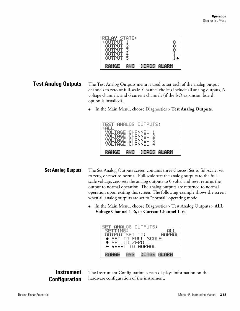
Operation Diagnostics Menu
Thermo Fisher Scientific Model 48i Instruction Manual 3-67
RELAY STATE: >OUTPUT 1 0 OUTPUT 2 0 OUTPUT 3 0 OUTPUT 4 1 OUTPUT 5 1 RANGE AVG DIAGS ALARM
The Test Analog Outputs menu is used to set each of the analog output channels to zero or full-scale. Channel choices include all analog outputs, 6 voltage channels, and 6 current channels (if the I/O expansion board option is installed).
● In the Main Menu, choose Diagnostics > Test Analog Outputs.
TEST ANALOG OUTPUTS: >ALL VOLTAGE CHANNEL 1 VOLTAGE CHANNEL 2 VOLTAGE CHANNEL 3 VOLTAGE CHANNEL 4 RANGE AVG DIAGS ALARM
The Set Analog Outputs screen contains three choices: Set to full-scale, set to zero, or reset to normal. Full-scale sets the analog outputs to the full-scale voltage, zero sets the analog outputs to 0 volts, and reset returns the output to normal operation. The analog outputs are returned to normal operation upon exiting this screen. The following example shows the screen when all analog outputs are set to “normal” operating mode.
● In the Main Menu, choose Diagnostics > Test Analog Outputs > ALL, Voltage Channel 1–6, or Current Channel 1–6.
SET ANALOG OUTPUTS: SETTING: ALL OUTPUT SET TO: NORMAL SET TO FULL SCALE SET TO ZERO RESET TO NORMAL RANGE AVG DIAGS ALARM
The Instrument Configuration screen displays information on the hardware configuration of the instrument.
Test Analog Outputs
Set Analog Outputs
Instrument Configuration
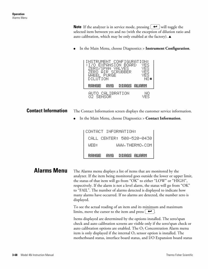
Operation Alarms Menu
3-68 Model 48i Instruction Manual Thermo Fisher Scientific
Note If the analyzer is in service mode, pressing will toggle the selected item between yes and no (with the exception of dilution ratio and auto calibration, which may be only enabled at the factory). ▲
● In the Main Menu, choose Diagnostics > Instrument Configuration.
INSTRUMENT CONFIGURATION: >I/O EXPANSION BOARD YES ZERO/SPAN VALVES YES ZERO AIR SCRUBBER YES WHEEL PURGE YES DILUTION NO RANGE AVG DIAGS ALARM
AUTO CALIBRATION NO O2 SENSOR YES
The Contact Information screen displays the customer service information.
● In the Main Menu, choose Diagnostics > Contact Information.
CONTACT INFORMATION: CALL CENTER: 508-520-0430 WEB: WWW.THERMO.COM RANGE AVG DIAGS ALARM
The Alarms menu displays a list of items that are monitored by the analyzer. If the item being monitored goes outside the lower or upper limit, the status of that item will go from “OK” to either “LOW” or “HIGH”, respectively. If the alarm is not a level alarm, the status will go from “OK” to “FAIL”. The number of alarms detected is displayed to indicate how many alarms have occurred. If no alarms are detected, the number zero is displayed.
To see the actual reading of an item and its minimum and maximum limits, move the cursor to the item and press .
Items displayed are determined by the options installed. The zero/span check and auto calibration screens are visible only if the zero/span check or auto calibration options are enabled. The O2 Concentration Alarm menu item is only displayed if the internal O2 sensor option is installed. The motherboard status, interface board status, and I/O Expansion board status
Contact Information
Alarms Menu
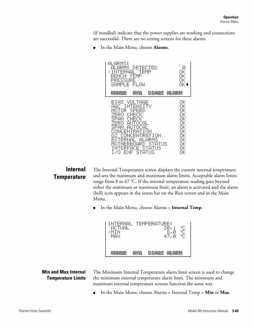
Operation Alarms Menu
Thermo Fisher Scientific Model 48i Instruction Manual 3-69
(if installed) indicate that the power supplies are working and connections are successful. There are no setting screens for these alarms.
● In the Main Menu, choose Alarms.
ALARMS: ALARMS DETECTED 0 >INTERNAL TEMP OK BENCH TEMP OK PRESSURE OK SAMPLE FLOW OK RANGE AVG DIAGS ALARM
BIAS VOLTAGE OK AGC INTENSITY OK MOTOR SPEED OK ZERO CHECK OK SPAN CHECK OK ZERO AUTOCAL OK SPAN AUTOCAL OK CONCENTRATION OK O2 CONCENTRATION OK EXTERNAL ALARMS OK MOTHERBOARD STATUS OK INTERFACE STATUS OK I/O EXP STATUS OK
The Internal Temperature screen displays the current internal temperature and sets the minimum and maximum alarm limits. Acceptable alarm limits range from 8 to 47 °C. If the internal temperature reading goes beyond either the minimum or maximum limit, an alarm is activated and the alarm (bell) icon appears in the status bar on the Run screen and in the Main Menu.
● In the Main Menu, choose Alarms > Internal Temp.
INTERNAL TEMPERATURE: ACTUAL 30.1
oC >MIN 8.0
oC MAX 47.0
oC RANGE AVG DIAGS ALARM
The Minimum Internal Temperature alarm limit screen is used to change the minimum internal temperature alarm limit. The minimum and maximum internal temperature screens function the same way.
● In the Main Menu, choose Alarms > Internal Temp > Min or Max.
Internal Temperature
Min and Max Internal Temperature Limits
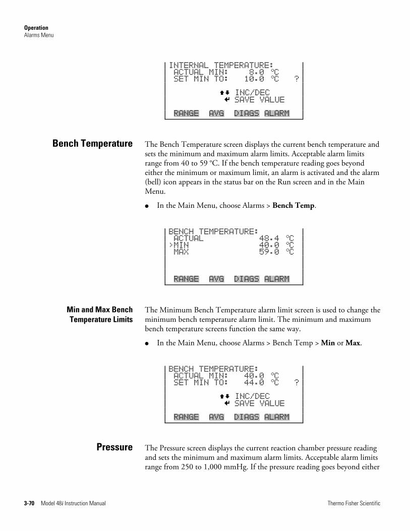
Operation Alarms Menu
3-70 Model 48i Instruction Manual Thermo Fisher Scientific
INTERNAL TEMPERATURE: ACTUAL MIN: 8.0
oC SET MIN TO: 10.0
oC ? INC/DEC SAVE VALUE RANGE AVG DIAGS ALARM
The Bench Temperature screen displays the current bench temperature and sets the minimum and maximum alarm limits. Acceptable alarm limits range from 40 to 59 °C. If the bench temperature reading goes beyond either the minimum or maximum limit, an alarm is activated and the alarm (bell) icon appears in the status bar on the Run screen and in the Main Menu.
● In the Main Menu, choose Alarms > Bench Temp.
BENCH TEMPERATURE: ACTUAL 48.4
oC >MIN 40.0
oC MAX 59.0
oC RANGE AVG DIAGS ALARM
The Minimum Bench Temperature alarm limit screen is used to change the minimum bench temperature alarm limit. The minimum and maximum bench temperature screens function the same way.
● In the Main Menu, choose Alarms > Bench Temp > Min or Max.
BENCH TEMPERATURE: ACTUAL MIN: 40.0
oC SET MIN TO: 44.0
oC ? INC/DEC SAVE VALUE RANGE AVG DIAGS ALARM
The Pressure screen displays the current reaction chamber pressure reading and sets the minimum and maximum alarm limits. Acceptable alarm limits range from 250 to 1,000 mmHg. If the pressure reading goes beyond either
Bench Temperature
Min and Max Bench Temperature Limits
Pressure
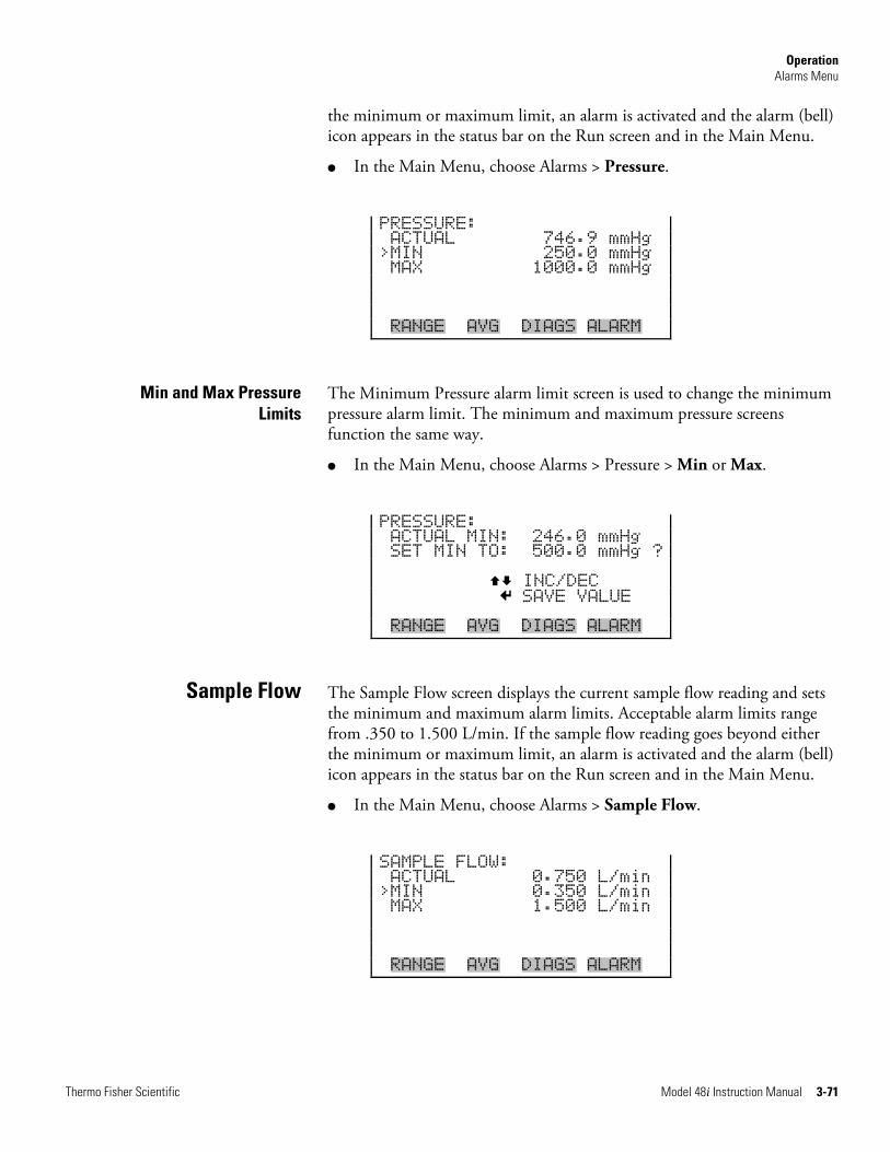
Operation Alarms Menu
Thermo Fisher Scientific Model 48i Instruction Manual 3-71
the minimum or maximum limit, an alarm is activated and the alarm (bell) icon appears in the status bar on the Run screen and in the Main Menu.
● In the Main Menu, choose Alarms > Pressure.
PRESSURE: ACTUAL 746.9 mmHg >MIN 250.0 mmHg MAX 1000.0 mmHg RANGE AVG DIAGS ALARM
The Minimum Pressure alarm limit screen is used to change the minimum pressure alarm limit. The minimum and maximum pressure screens function the same way.
● In the Main Menu, choose Alarms > Pressure > Min or Max.
PRESSURE: ACTUAL MIN: 246.0 mmHg SET MIN TO: 500.0 mmHg ? INC/DEC SAVE VALUE RANGE AVG DIAGS ALARM
The Sample Flow screen displays the current sample flow reading and sets the minimum and maximum alarm limits. Acceptable alarm limits range from .350 to 1.500 L/min. If the sample flow reading goes beyond either the minimum or maximum limit, an alarm is activated and the alarm (bell) icon appears in the status bar on the Run screen and in the Main Menu.
● In the Main Menu, choose Alarms > Sample Flow.
SAMPLE FLOW: ACTUAL 0.750 L/min >MIN 0.350 L/min MAX 1.500 L/min RANGE AVG DIAGS ALARM
Min and Max Pressure Limits
Sample Flow
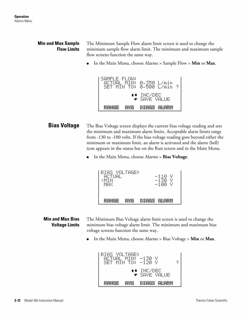
Operation Alarms Menu
3-72 Model 48i Instruction Manual Thermo Fisher Scientific
The Minimum Sample Flow alarm limit screen is used to change the minimum sample flow alarm limit. The minimum and maximum sample flow screens function the same way.
● In the Main Menu, choose Alarms > Sample Flow > Min or Max.
SAMPLE FLOW: ACTUAL MIN: 0.350 L/min SET MIN TO: 0.500 L/min ? INC/DEC SAVE VALUE RANGE AVG DIAGS ALARM
The Bias Voltage screen displays the current bias voltage reading and sets the minimum and maximum alarm limits. Acceptable alarm limits range from -130 to -100 volts. If the bias voltage reading goes beyond either the minimum or maximum limit, an alarm is activated and the alarm (bell) icon appears in the status bar on the Run screen and in the Main Menu.
● In the Main Menu, choose Alarms > Bias Voltage.
BIAS VOLTAGE: ACTUAL -110 V >MIN -130 V MAX -100 V RANGE AVG DIAGS ALARM
The Minimum Bias Voltage alarm limit screen is used to change the minimum bias voltage alarm limit. The minimum and maximum bias voltage screens function the same way.
● In the Main Menu, choose Alarms > Bias Voltage > Min or Max.
BIAS VOLTAGE: ACTUAL MIN: -130 V SET MIN TO: -120 V ? INC/DEC SAVE VALUE RANGE AVG DIAGS ALARM
Min and Max Sample Flow Limits
Bias Voltage
Min and Max Bias Voltage Limits
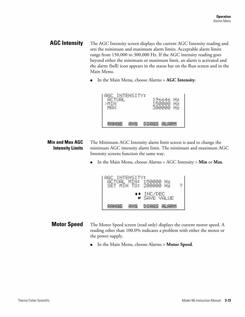
Operation Alarms Menu
Thermo Fisher Scientific Model 48i Instruction Manual 3-73
The AGC Intensity screen displays the current AGC Intensity reading and sets the minimum and maximum alarm limits. Acceptable alarm limits range from 150,000 to 300,000 Hz. If the AGC intensity reading goes beyond either the minimum or maximum limit, an alarm is activated and the alarm (bell) icon appears in the status bar on the Run screen and in the Main Menu.
● In the Main Menu, choose Alarms > AGC Intensity.
AGC INTENSITY: ACTUAL 196646 Hz >MIN 150000 Hz MAX 300000 Hz RANGE AVG DIAGS ALARM
The Minimum AGC Intensity alarm limit screen is used to change the minimum AGC intensity alarm limit. The minimum and maximum AGC Intensity screens function the same way.
● In the Main Menu, choose Alarms > AGC Intensity > Min or Max.
AGC INTENSITY: ACTUAL MIN: 150000 Hz SET MIN TO: 200000 Hz ? INC/DEC SAVE VALUE RANGE AVG DIAGS ALARM
The Motor Speed screen (read only) displays the current motor speed. A reading other than 100.0% indicates a problem with either the motor or the power supply.
● In the Main Menu, choose Alarms > Motor Speed.
AGC Intensity
Min and Max AGC Intensity Limits
Motor Speed
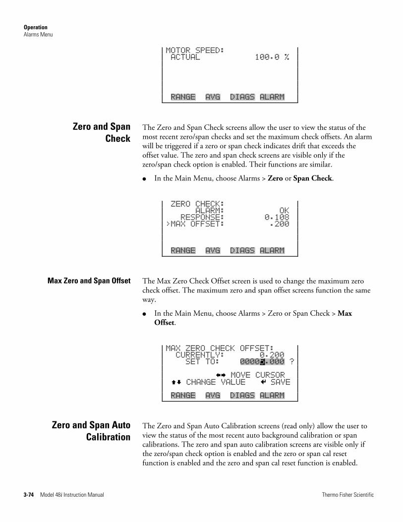
Operation Alarms Menu
3-74 Model 48i Instruction Manual Thermo Fisher Scientific
MOTOR SPEED: ACTUAL 100.0 % RANGE AVG DIAGS ALARM
The Zero and Span Check screens allow the user to view the status of the most recent zero/span checks and set the maximum check offsets. An alarm will be triggered if a zero or span check indicates drift that exceeds the offset value. The zero and span check screens are visible only if the zero/span check option is enabled. Their functions are similar.
● In the Main Menu, choose Alarms > Zero or Span Check.
ZERO CHECK: ALARM: OK RESPONSE: 0.108 >MAX OFFSET: .200 RANGE AVG DIAGS ALARM
The Max Zero Check Offset screen is used to change the maximum zero check offset. The maximum zero and span offset screens function the same way.
● In the Main Menu, choose Alarms > Zero or Span Check > Max Offset.
MAX ZERO CHECK OFFSET: CURRENTLY: 0.200 SET TO: 00005.000 ? MOVE CURSOR CHANGE VALUE SAVE RANGE AVG DIAGS ALARM
The Zero and Span Auto Calibration screens (read only) allow the user to view the status of the most recent auto background calibration or span calibrations. The zero and span auto calibration screens are visible only if the zero/span check option is enabled and the zero or span cal reset function is enabled and the zero and span cal reset function is enabled.
Zero and Span Check
Max Zero and Span Offset
Zero and Span Auto Calibration
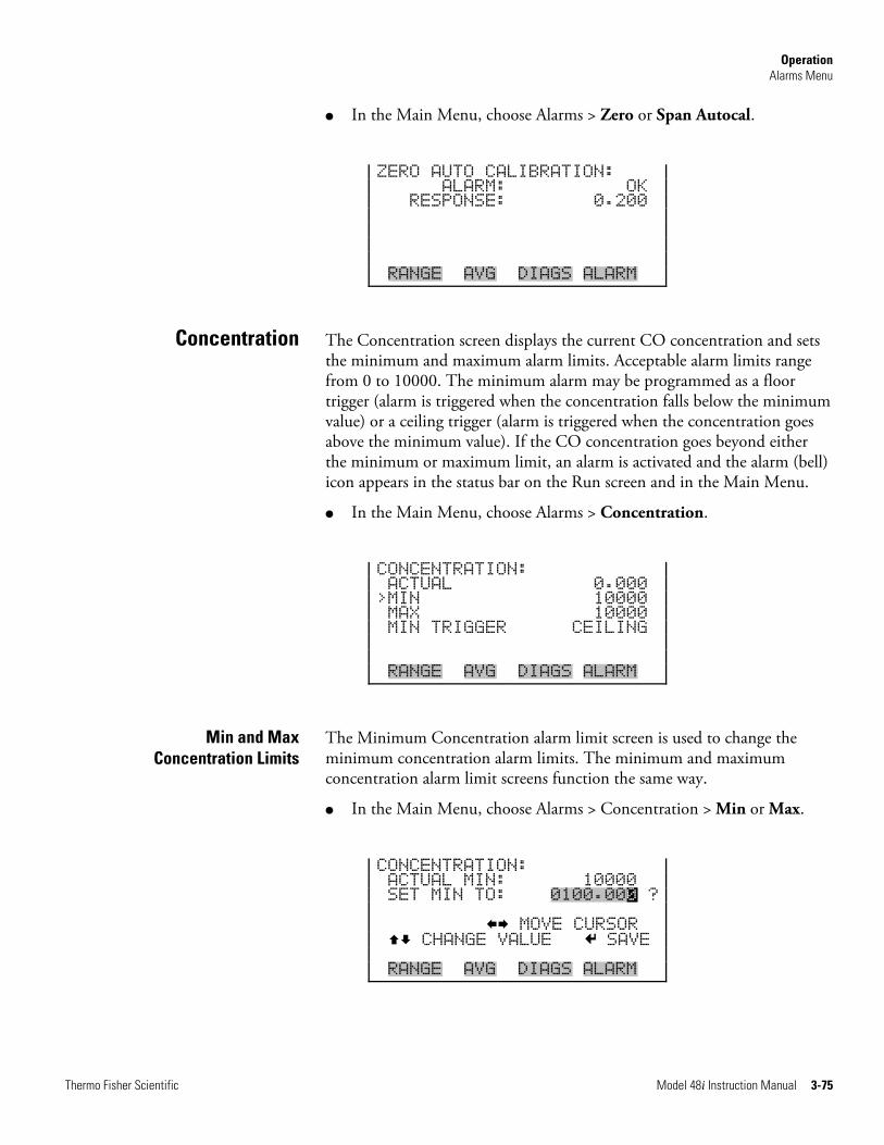
Operation Alarms Menu
Thermo Fisher Scientific Model 48i Instruction Manual 3-75
● In the Main Menu, choose Alarms > Zero or Span Autocal.
ZERO AUTO CALIBRATION: ALARM: OK RESPONSE: 0.200 RANGE AVG DIAGS ALARM
The Concentration screen displays the current CO concentration and sets the minimum and maximum alarm limits. Acceptable alarm limits range from 0 to 10000. The minimum alarm may be programmed as a floor trigger (alarm is triggered when the concentration falls below the minimum value) or a ceiling trigger (alarm is triggered when the concentration goes above the minimum value). If the CO concentration goes beyond either the minimum or maximum limit, an alarm is activated and the alarm (bell) icon appears in the status bar on the Run screen and in the Main Menu.
● In the Main Menu, choose Alarms > Concentration.
CONCENTRATION: ACTUAL 0.000 >MIN 10000 MAX 10000 MIN TRIGGER CEILING RANGE AVG DIAGS ALARM
The Minimum Concentration alarm limit screen is used to change the minimum concentration alarm limits. The minimum and maximum concentration alarm limit screens function the same way.
● In the Main Menu, choose Alarms > Concentration > Min or Max.
CONCENTRATION: ACTUAL MIN: 10000 SET MIN TO: 0100.000 ? MOVE CURSOR CHANGE VALUE SAVE RANGE AVG DIAGS ALARM
Concentration
Min and Max Concentration Limits
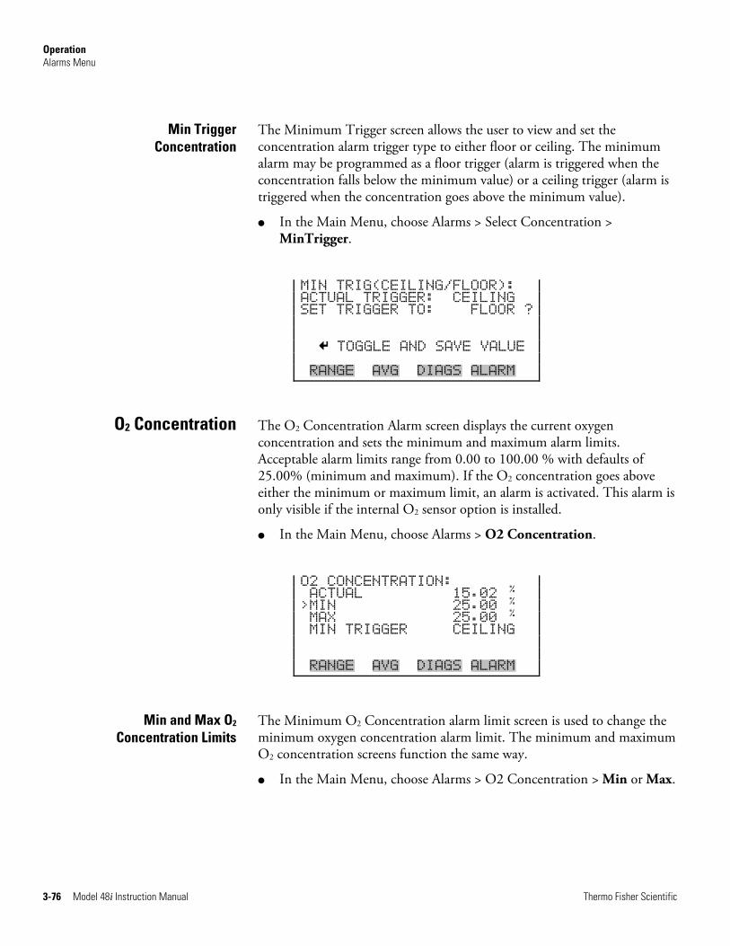
Operation Alarms Menu
3-76 Model 48i Instruction Manual Thermo Fisher Scientific
The Minimum Trigger screen allows the user to view and set the concentration alarm trigger type to either floor or ceiling. The minimum alarm may be programmed as a floor trigger (alarm is triggered when the concentration falls below the minimum value) or a ceiling trigger (alarm is triggered when the concentration goes above the minimum value).
● In the Main Menu, choose Alarms > Select Concentration > MinTrigger.
MIN TRIG(CEILING/FLOOR): ACTUAL TRIGGER: CEILING SET TRIGGER TO: FLOOR ? TOGGLE AND SAVE VALUE RANGE AVG DIAGS ALARM
The O2 Concentration Alarm screen displays the current oxygen concentration and sets the minimum and maximum alarm limits. Acceptable alarm limits range from 0.00 to 100.00 % with defaults of 25.00% (minimum and maximum). If the O2 concentration goes above either the minimum or maximum limit, an alarm is activated. This alarm is only visible if the internal O2 sensor option is installed.
● In the Main Menu, choose Alarms > O2 Concentration.
O2 CONCENTRATION: ACTUAL 15.02
% >MIN 25.00
% MAX 25.00
% MIN TRIGGER CEILING RANGE AVG DIAGS ALARM
The Minimum O2 Concentration alarm limit screen is used to change the minimum oxygen concentration alarm limit. The minimum and maximum O2 concentration screens function the same way.
● In the Main Menu, choose Alarms > O2 Concentration > Min or Max.
Min Trigger Concentration
O2 Concentration
Min and Max O2 Concentration Limits
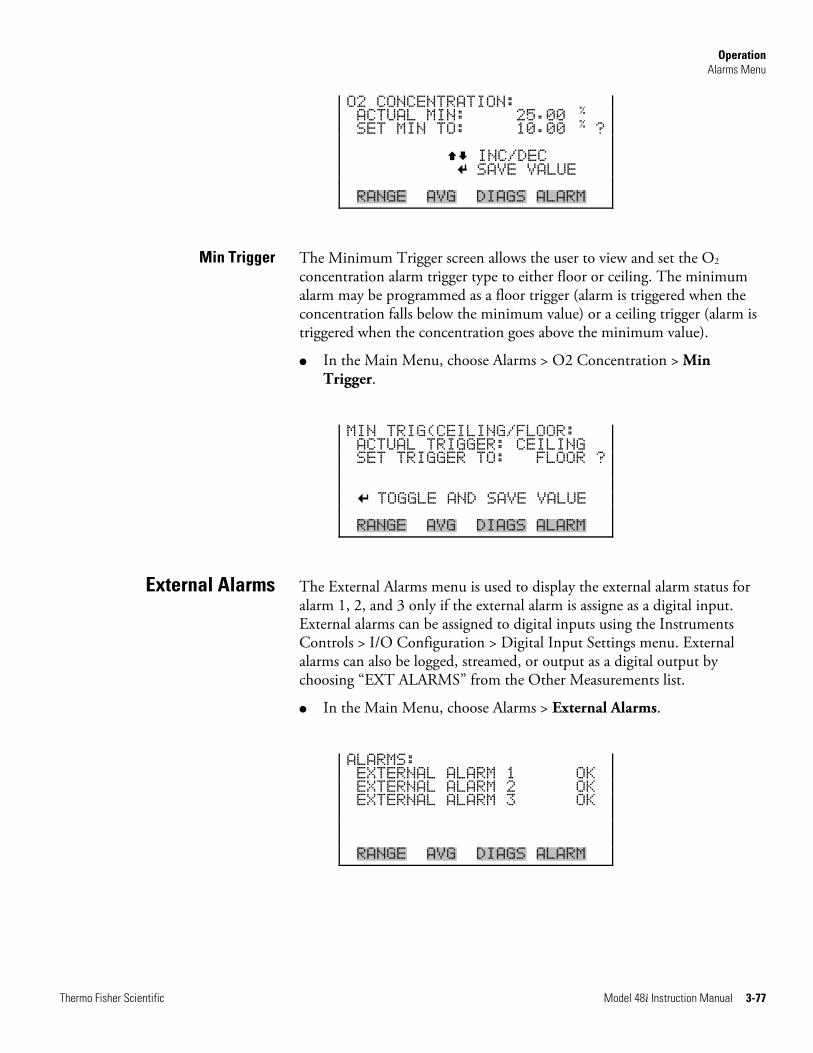
Operation Alarms Menu
Thermo Fisher Scientific Model 48i Instruction Manual 3-77
O2 CONCENTRATION: ACTUAL MIN: 25.00
% SET MIN TO: 10.00
% ? INC/DEC SAVE VALUE RANGE AVG DIAGS ALARM
The Minimum Trigger screen allows the user to view and set the O2 concentration alarm trigger type to either floor or ceiling. The minimum alarm may be programmed as a floor trigger (alarm is triggered when the concentration falls below the minimum value) or a ceiling trigger (alarm is triggered when the concentration goes above the minimum value).
● In the Main Menu, choose Alarms > O2 Concentration > Min Trigger.
MIN TRIG(CEILING/FLOOR: ACTUAL TRIGGER: CEILING SET TRIGGER TO: FLOOR ? TOGGLE AND SAVE VALUE RANGE AVG DIAGS ALARM
The External Alarms menu is used to display the external alarm status for alarm 1, 2, and 3 only if the external alarm is assigne as a digital input. External alarms can be assigned to digital inputs using the Instruments Controls > I/O Configuration > Digital Input Settings menu. External alarms can also be logged, streamed, or output as a digital output by choosing “EXT ALARMS” from the Other Measurements list.
● In the Main Menu, choose Alarms > External Alarms.
ALARMS: EXTERNAL ALARM 1 OK EXTERNAL ALARM 2 OK EXTERNAL ALARM 3 OK RANGE AVG DIAGS ALARM
Min Trigger
External Alarms
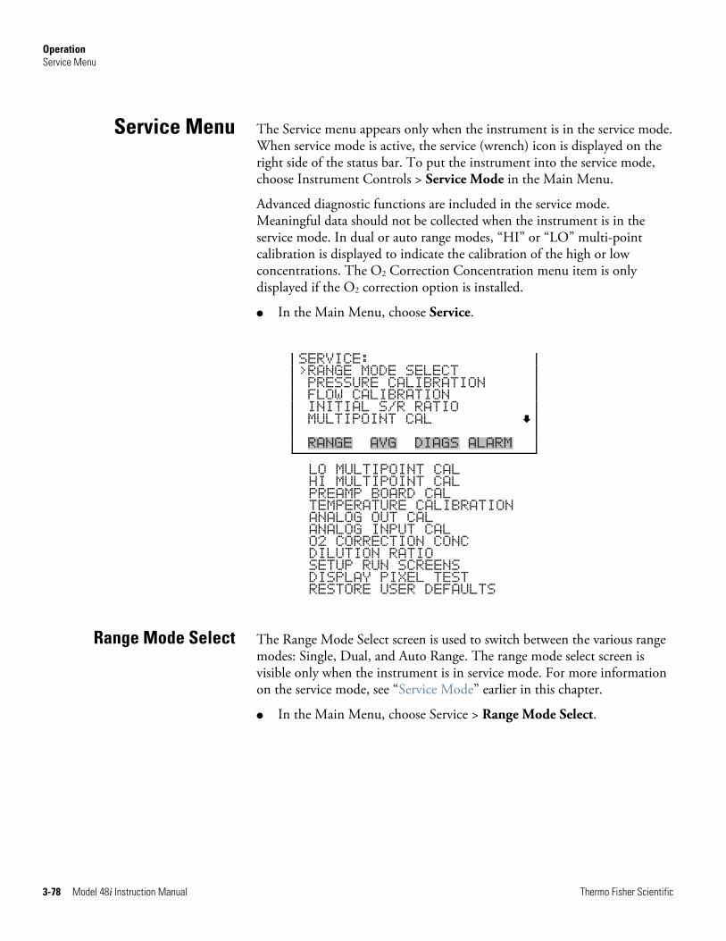
Operation Service Menu
3-78 Model 48i Instruction Manual Thermo Fisher Scientific
The Service menu appears only when the instrument is in the service mode. When service mode is active, the service (wrench) icon is displayed on the right side of the status bar. To put the instrument into the service mode, choose Instrument Controls > Service Mode in the Main Menu.
Advanced diagnostic functions are included in the service mode. Meaningful data should not be collected when the instrument is in the service mode. In dual or auto range modes, “HI” or “LO” multi-point calibration is displayed to indicate the calibration of the high or low concentrations. The O2 Correction Concentration menu item is only displayed if the O2 correction option is installed.
● In the Main Menu, choose Service.
SERVICE: >RANGE MODE SELECT PRESSURE CALIBRATION FLOW CALIBRATION INITIAL S/R RATIO MULTIPOINT CAL RANGE AVG DIAGS ALARM
LO MULTIPOINT CAL HI MULTIPOINT CAL PREAMP BOARD CAL TEMPERATURE CALIBRATION ANALOG OUT CAL ANALOG INPUT CAL O2 CORRECTION CONC DILUTION RATIO SETUP RUN SCREENS DISPLAY PIXEL TEST RESTORE USER DEFAULTS
The Range Mode Select screen is used to switch between the various range modes: Single, Dual, and Auto Range. The range mode select screen is visible only when the instrument is in service mode. For more information on the service mode, see “Service Mode” earlier in this chapter.
● In the Main Menu, choose Service > Range Mode Select.
Service Menu
Range Mode Select
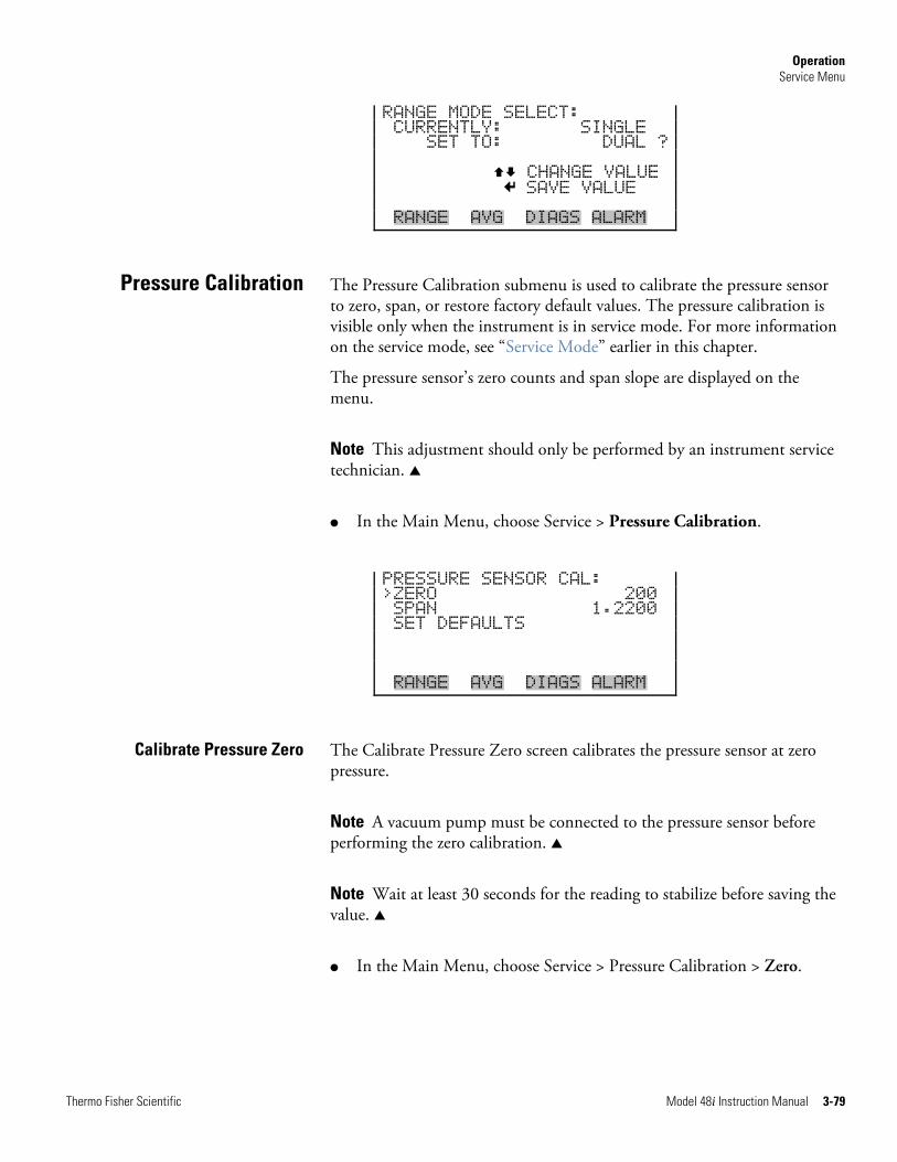
Operation Service Menu
Thermo Fisher Scientific Model 48i Instruction Manual 3-79
RANGE MODE SELECT: CURRENTLY: SINGLE SET TO: DUAL ? CHANGE VALUE SAVE VALUE RANGE AVG DIAGS ALARM
The Pressure Calibration submenu is used to calibrate the pressure sensor to zero, span, or restore factory default values. The pressure calibration is visible only when the instrument is in service mode. For more information on the service mode, see “Service Mode” earlier in this chapter.
The pressure sensor’s zero counts and span slope are displayed on the menu.
Note This adjustment should only be performed by an instrument service technician. ▲
● In the Main Menu, choose Service > Pressure Calibration.
PRESSURE SENSOR CAL: >ZERO 200 SPAN 1.2200 SET DEFAULTS RANGE AVG DIAGS ALARM
The Calibrate Pressure Zero screen calibrates the pressure sensor at zero pressure.
Note A vacuum pump must be connected to the pressure sensor before performing the zero calibration. ▲
Note Wait at least 30 seconds for the reading to stabilize before saving the value. ▲
● In the Main Menu, choose Service > Pressure Calibration > Zero.
Pressure Calibration
Calibrate Pressure Zero
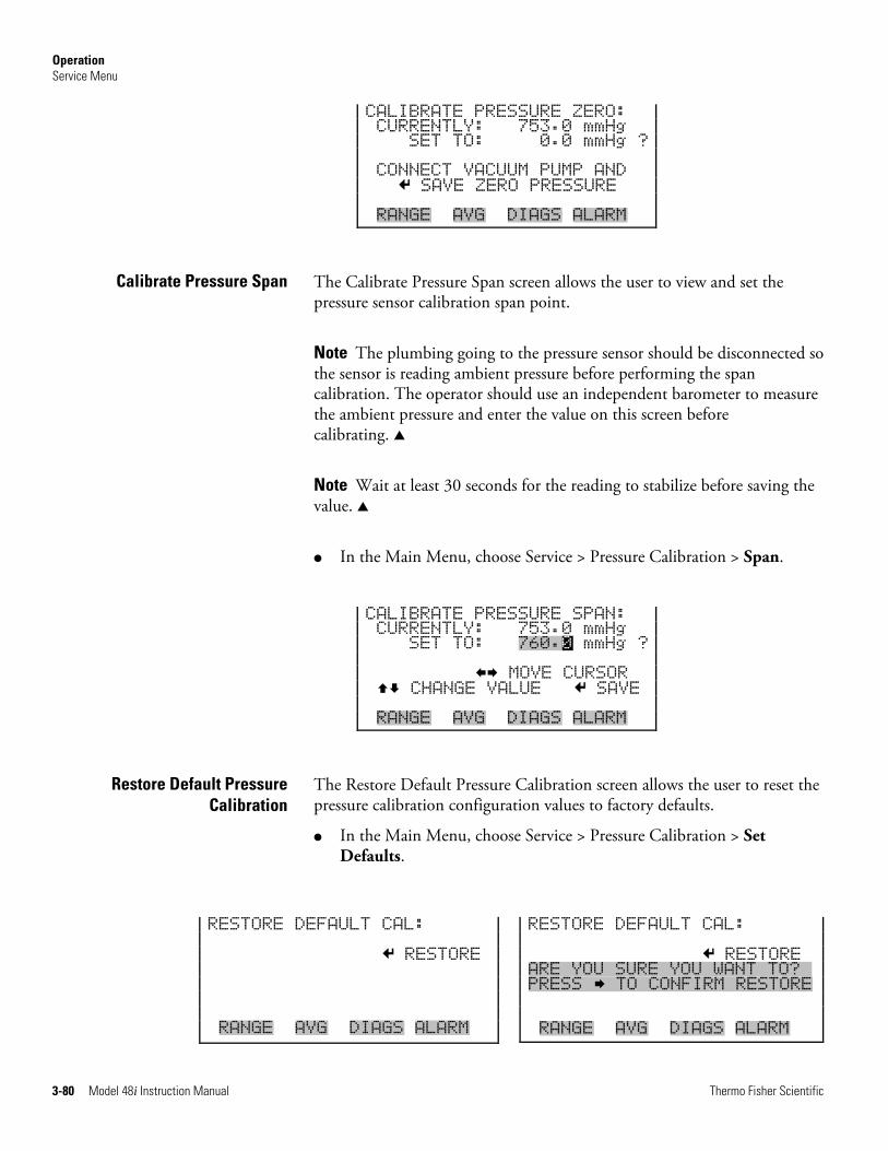
Operation Service Menu
3-80 Model 48i Instruction Manual Thermo Fisher Scientific
CALIBRATE PRESSURE ZERO: CURRENTLY: 753.0 mmHg SET TO: 0.0 mmHg ? CONNECT VACUUM PUMP AND SAVE ZERO PRESSURE RANGE AVG DIAGS ALARM
The Calibrate Pressure Span screen allows the user to view and set the pressure sensor calibration span point.
Note The plumbing going to the pressure sensor should be disconnected so the sensor is reading ambient pressure before performing the span calibration. The operator should use an independent barometer to measure the ambient pressure and enter the value on this screen before calibrating. ▲
Note Wait at least 30 seconds for the reading to stabilize before saving the value. ▲
● In the Main Menu, choose Service > Pressure Calibration > Span.
CALIBRATE PRESSURE SPAN: CURRENTLY: 753.0 mmHg SET TO: 760.0 mmHg ? MOVE CURSOR CHANGE VALUE SAVE RANGE AVG DIAGS ALARM
The Restore Default Pressure Calibration screen allows the user to reset the pressure calibration configuration values to factory defaults.
● In the Main Menu, choose Service > Pressure Calibration > Set Defaults.
Calibrate Pressure Span
Restore Default Pressure Calibration
RESTORE DEFAULT CAL: RESTORE RANGE AVG DIAGS ALARM
RESTORE DEFAULT CAL: RESTORE ARE YOU SURE YOU WANT TO?x PRESS TO CONFIRM RESTORE RANGE AVG DIAGS ALARM
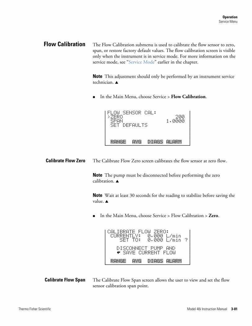
Operation Service Menu
Thermo Fisher Scientific Model 48i Instruction Manual 3-81
The Flow Calibration submenu is used to calibrate the flow sensor to zero, span, or restore factory default values. The flow calibration screen is visible only when the instrument is in service mode. For more information on the service mode, see “Service Mode” earlier in the chapter.
Note This adjustment should only be performed by an instrument service technician. ▲
● In the Main Menu, choose Service > Flow Calibration.
FLOW SENSOR CAL: >ZERO 200 SPAN 1.0000 SET DEFAULTS RANGE AVG DIAGS ALARM
The Calibrate Flow Zero screen calibrates the flow sensor at zero flow.
Note The pump must be disconnected before performing the zero calibration. ▲
Note Wait at least 30 seconds for the reading to stabilize before saving the value. ▲
● In the Main Menu, choose Service > Flow Calibration > Zero.
CALIBRATE FLOW ZERO: CURRENTLY: 0.000 L/min SET TO: 0.000 L/min ? DISCONNECT PUMP AND SAVE CURRENT FLOW RANGE AVG DIAGS ALARM
The Calibrate Flow Span screen allows the user to view and set the flow sensor calibration span point.
Flow Calibration
Calibrate Flow Zero
Calibrate Flow Span
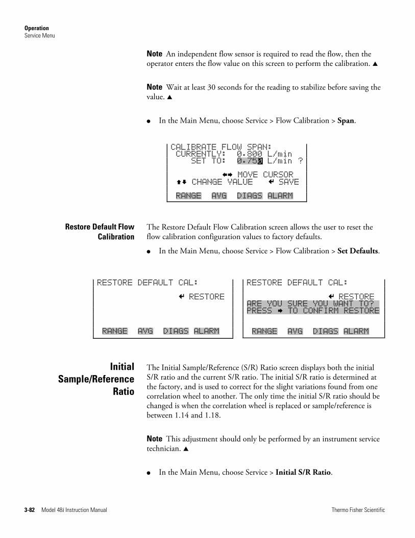
Operation Service Menu
3-82 Model 48i Instruction Manual Thermo Fisher Scientific
Note An independent flow sensor is required to read the flow, then the operator enters the flow value on this screen to perform the calibration. ▲
Note Wait at least 30 seconds for the reading to stabilize before saving the value. ▲
● In the Main Menu, choose Service > Flow Calibration > Span.
CALIBRATE FLOW SPAN: CURRENTLY: 0.800 L/min SET TO: 0.750 L/min ? MOVE CURSOR CHANGE VALUE SAVE RANGE AVG DIAGS ALARM
The Restore Default Flow Calibration screen allows the user to reset the flow calibration configuration values to factory defaults.
● In the Main Menu, choose Service > Flow Calibration > Set Defaults.
The Initial Sample/Reference (S/R) Ratio screen displays both the initial S/R ratio and the current S/R ratio. The initial S/R ratio is determined at the factory, and is used to correct for the slight variations found from one correlation wheel to another. The only time the initial S/R ratio should be changed is when the correlation wheel is replaced or sample/reference is between 1.14 and 1.18.
Note This adjustment should only be performed by an instrument service technician. ▲
● In the Main Menu, choose Service > Initial S/R Ratio.
Restore Default Flow Calibration
Initial Sample/Reference
Ratio
RESTORE DEFAULT CAL: RESTORE RANGE AVG DIAGS ALARM
RESTORE DEFAULT CAL: RESTORE ARE YOU SURE YOU WANT TO?x PRESS TO CONFIRM RESTORE RANGE AVG DIAGS ALARM
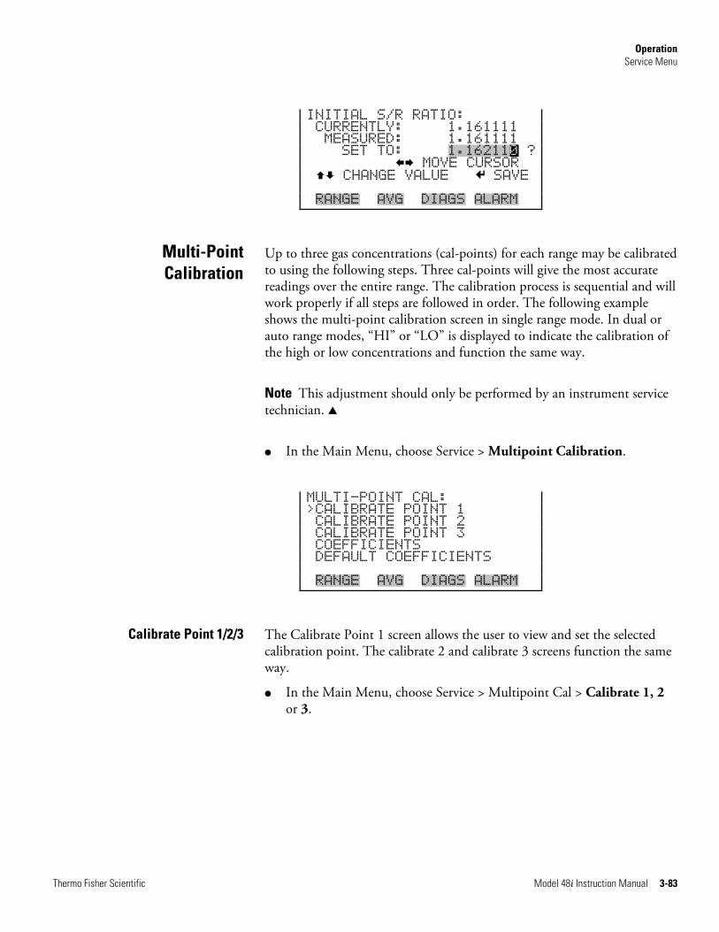
Operation Service Menu
Thermo Fisher Scientific Model 48i Instruction Manual 3-83
INITIAL S/R RATIO: CURRENTLY: 1.161111 MEASURED: 1.161111 SET TO: 1.162110 ? MOVE CURSOR CHANGE VALUE SAVE RANGE AVG DIAGS ALARM
Up to three gas concentrations (cal-points) for each range may be calibrated to using the following steps. Three cal-points will give the most accurate readings over the entire range. The calibration process is sequential and will work properly if all steps are followed in order. The following example shows the multi-point calibration screen in single range mode. In dual or auto range modes, “HI” or “LO” is displayed to indicate the calibration of the high or low concentrations and function the same way.
Note This adjustment should only be performed by an instrument service technician. ▲
● In the Main Menu, choose Service > Multipoint Calibration.
MULTI-POINT CAL: >CALIBRATE POINT 1 CALIBRATE POINT 2 CALIBRATE POINT 3 COEFFICIENTS DEFAULT COEFFICIENTS RANGE AVG DIAGS ALARM
The Calibrate Point 1 screen allows the user to view and set the selected calibration point. The calibrate 2 and calibrate 3 screens function the same way.
● In the Main Menu, choose Service > Multipoint Cal > Calibrate 1, 2 or 3.
Multi-Point Calibration
Calibrate Point 1/2/3
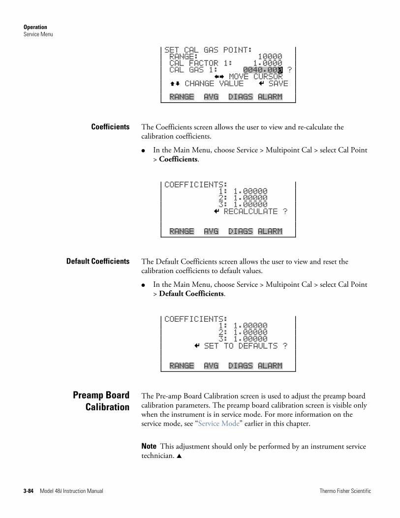
Operation Service Menu
3-84 Model 48i Instruction Manual Thermo Fisher Scientific
SET CAL GAS POINT: RANGE: 10000 CAL FACTOR 1: 1.0000 CAL GAS 1: 0040.000 ? MOVE CURSOR CHANGE VALUE SAVE RANGE AVG DIAGS ALARM
The Coefficients screen allows the user to view and re-calculate the calibration coefficients.
● In the Main Menu, choose Service > Multipoint Cal > select Cal Point > Coefficients.
COEFFICIENTS: 1: 1.00000 2: 1.00000 3: 1.00000 RECALCULATE ? RANGE AVG DIAGS ALARM
The Default Coefficients screen allows the user to view and reset the calibration coefficients to default values.
● In the Main Menu, choose Service > Multipoint Cal > select Cal Point > Default Coefficients.
COEFFICIENTS: 1: 1.00000 2: 1.00000 3: 1.00000 SET TO DEFAULTS ? RANGE AVG DIAGS ALARM
The Pre-amp Board Calibration screen is used to adjust the preamp board calibration parameters. The preamp board calibration screen is visible only when the instrument is in service mode. For more information on the service mode, see “Service Mode” earlier in this chapter.
Note This adjustment should only be performed by an instrument service technician. ▲
Coefficients
Default Coefficients
Preamp Board Calibration
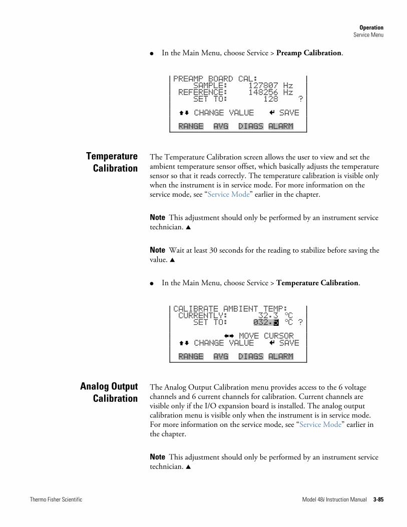
Operation Service Menu
Thermo Fisher Scientific Model 48i Instruction Manual 3-85
● In the Main Menu, choose Service > Preamp Calibration.
PREAMP BOARD CAL: SAMPLE: 127807 Hz REFERENCE: 148256 Hz SET TO: 128 ? CHANGE VALUE SAVE RANGE AVG DIAGS ALARM
The Temperature Calibration screen allows the user to view and set the ambient temperature sensor offset, which basically adjusts the temperature sensor so that it reads correctly. The temperature calibration is visible only when the instrument is in service mode. For more information on the service mode, see “Service Mode” earlier in the chapter.
Note This adjustment should only be performed by an instrument service technician. ▲
Note Wait at least 30 seconds for the reading to stabilize before saving the value. ▲
● In the Main Menu, choose Service > Temperature Calibration.
CALIBRATE AMBIENT TEMP: CURRENTLY: 32.3
oC SET TO: 032.5
oC ? MOVE CURSOR CHANGE VALUE SAVE RANGE AVG DIAGS ALARM
The Analog Output Calibration menu provides access to the 6 voltage channels and 6 current channels for calibration. Current channels are visible only if the I/O expansion board is installed. The analog output calibration menu is visible only when the instrument is in service mode. For more information on the service mode, see “Service Mode” earlier in the chapter.
Note This adjustment should only be performed by an instrument service technician. ▲
Temperature Calibration
Analog Output Calibration
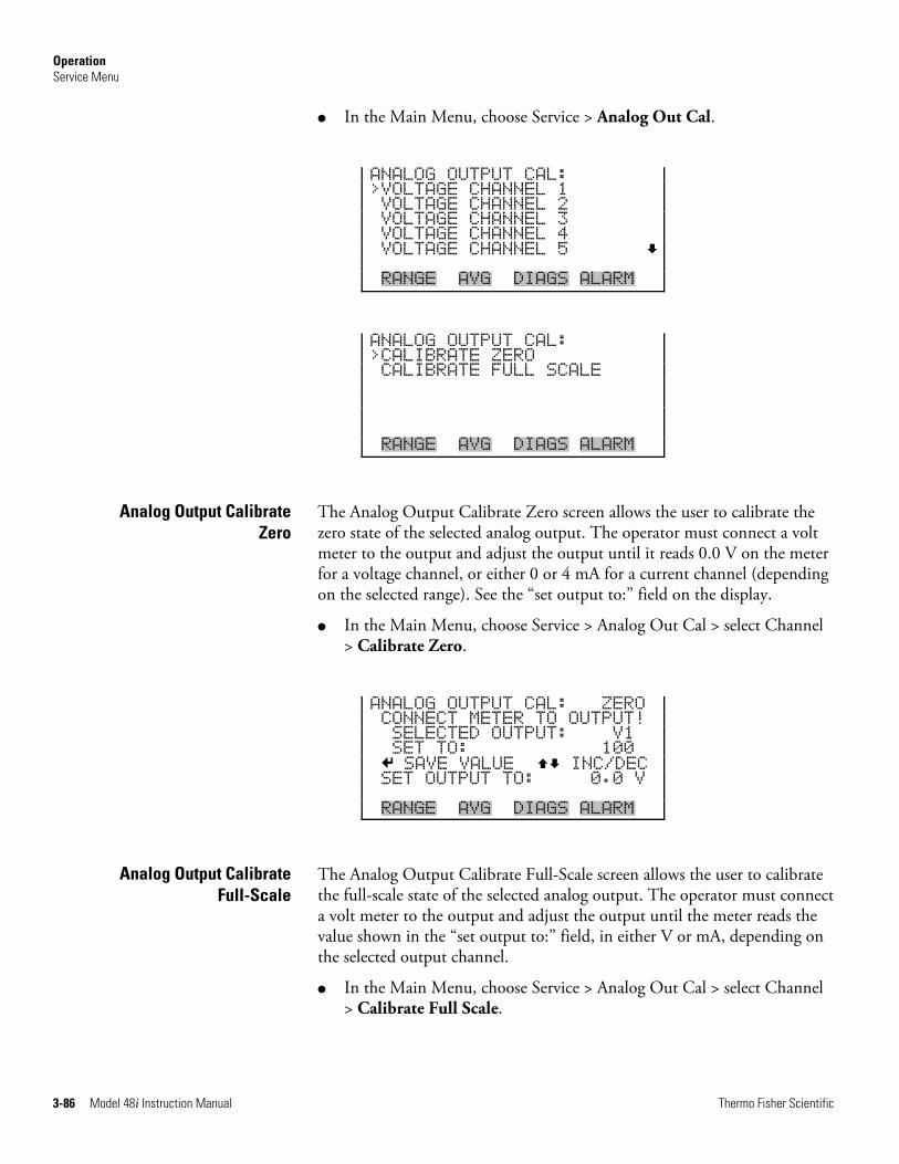
Operation Service Menu
3-86 Model 48i Instruction Manual Thermo Fisher Scientific
● In the Main Menu, choose Service > Analog Out Cal.
ANALOG OUTPUT CAL: >VOLTAGE CHANNEL 1 VOLTAGE CHANNEL 2 VOLTAGE CHANNEL 3 VOLTAGE CHANNEL 4 VOLTAGE CHANNEL 5 RANGE AVG DIAGS ALARM
ANALOG OUTPUT CAL: >CALIBRATE ZERO CALIBRATE FULL SCALE RANGE AVG DIAGS ALARM
The Analog Output Calibrate Zero screen allows the user to calibrate the zero state of the selected analog output. The operator must connect a volt meter to the output and adjust the output until it reads 0.0 V on the meter for a voltage channel, or either 0 or 4 mA for a current channel (depending on the selected range). See the “set output to:” field on the display.
● In the Main Menu, choose Service > Analog Out Cal > select Channel > Calibrate Zero.
ANALOG OUTPUT CAL: ZERO CONNECT METER TO OUTPUT! SELECTED OUTPUT: V1 SET TO: 100 SAVE VALUE INC/DEC SET OUTPUT TO: 0.0 V RANGE AVG DIAGS ALARM
The Analog Output Calibrate Full-Scale screen allows the user to calibrate the full-scale state of the selected analog output. The operator must connect a volt meter to the output and adjust the output until the meter reads the value shown in the “set output to:” field, in either V or mA, depending on the selected output channel.
● In the Main Menu, choose Service > Analog Out Cal > select Channel > Calibrate Full Scale.
Analog Output Calibrate Zero
Analog Output Calibrate Full-Scale
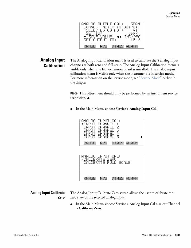
Operation Service Menu
Thermo Fisher Scientific Model 48i Instruction Manual 3-87
ANALOG OUTPUT CAL: SPAN CONNECT METER TO OUTPUT! SELECTED OUTPUT: V1 SET TO: 3697 SAVE VALUE INC/DEC SET OUTPUT TO: 10 V RANGE AVG DIAGS ALARM
The Analog Input Calibration menu is used to calibrate the 8 analog input channels at both zero and full-scale. The Analog Input Calibration menu is visible only when the I/O expansion board is installed. The analog input calibration menu is visible only when the instrument is in service mode. For more information on the service mode, see “Service Mode” earlier in the chapter.
Note This adjustment should only be performed by an instrument service technician. ▲
● In the Main Menu, choose Service > Analog Input Cal.
ANALOG INPUT CAL: >INPUT CHANNEL 1 INPUT CHANNEL 2 INPUT CHANNEL 3 INPUT CHANNEL 4 INPUT CHANNEL 5 RANGE AVG DIAGS ALARM
ANALOG INPUT CAL: >CALIBRATE ZERO CALIBRATE FULL SCALE RANGE AVG DIAGS ALARM
The Analog Input Calibrate Zero screen allows the user to calibrate the zero state of the selected analog input.
● In the Main Menu, choose Service > Analog Input Cal > select Channel > Calibrate Zero.
Analog Input Calibration
Analog Input Calibrate Zero
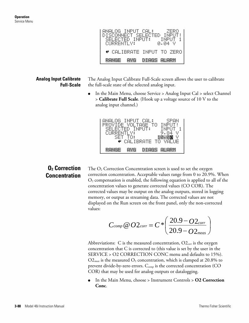
Operation Service Menu
3-88 Model 48i Instruction Manual Thermo Fisher Scientific
ANALOG INPUT CAL: ZERO DISCONNECT SELECTED INPUT! SELECTED INPUT: INPUT 1 CURRENTLY: 0.04 V CALIBRATE INPUT TO ZERO RANGE AVG DIAGS ALARM
The Analog Input Calibrate Full-Scale screen allows the user to calibrate the full-scale state of the selected analog input.
● In the Main Menu, choose Service > Analog Input Cal > select Channel > Calibrate Full Scale. (Hook up a voltage source of 10 V to the analog input channel.)
ANALOG INPUT CAL: SPAN PROVIDE VOLTAGE TO INPUT! SELECTED INPUT: INPUT 1 CURRENTLY: 9.84 V SET TO: 10.00 V CALIBRATE TO VALUE RANGE AVG DIAGS ALARM
The O2 Correction Concentration screen is used to set the oxygen correction concentration. Acceptable values range from 0 to 20.9%. When O2 compensation is enabled, the following equation is applied to all of the concentration values to generate corrected values (CO COR). The corrected values may be output on the analog outputs, stored in logging memory, or output as streaming data. The corrected values are not displayed on the Run screen on the front panel, only the non-corrected values:
⎟⎠⎞
⎜⎝⎛
−−
=29.2029.20*2@
OOCOC
meas
corrcorrcomp
Abbreviations: C is the measured concentration, O2corr is the oxygen concentration that C is corrected to (this value is set by the user in the SERVICE > O2 CORRECTION CONC menu and defaults to 15%). O2meas is the measured O2 concentration, which is clamped at 20.8% to prevent divide-by-zero errors. Ccomp is the corrected concentration (CO COR) that may be used for analog outputs or datalogging.
● In the Main Menu, choose > Instrument Controls > O2 Correction Conc.
Analog Input Calibrate Full-Scale
O2 Correction Concentration
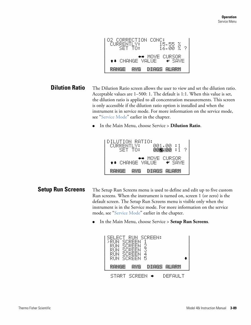
Operation Service Menu
Thermo Fisher Scientific Model 48i Instruction Manual 3-89
O2 CORRECTION CONC: CURRENTLY: 15.55 % SET TO: 16.00 % ? MOVE CURSOR CHANGE VALUE SAVE RANGE AVG DIAGS ALARM
The Dilution Ratio screen allows the user to view and set the dilution ratio. Acceptable values are 1–500: 1. The default is 1:1. When this value is set, the dilution ratio is applied to all concentration measurements. This screen is only accessible if the dilution ratio option is installed and when the instrument is in service mode. For more information on the service mode, see “Service Mode” earlier in the chapter.
● In the Main Menu, choose Service > Dilution Ratio.
DILUTION RATIO: CURRENTLY: 001.00 :1 SET TO: 002.00 :1 ? MOVE CURSOR CHANGE VALUE SAVE RANGE AVG DIAGS ALARM
The Setup Run Screens menu is used to define and edit up to five custom Run screens. When the instrument is turned on, screen 1 (or zero) is the default screen. The Setup Run Screens menu is visible only when the instrument is in the Service mode. For more information on the service mode, see “Service Mode” earlier in the chapter.
● In the Main Menu, choose Service > Setup Run Screens.
SELECT RUN SCREEN: >RUN SCREEN 1 RUN SCREEN 2 RUN SCREEN 3 RUN SCREEN 4 RUN SCREEN 5 RANGE AVG DIAGS ALARM
START SCREEN DEFAULT
Dilution Ratio
Setup Run Screens
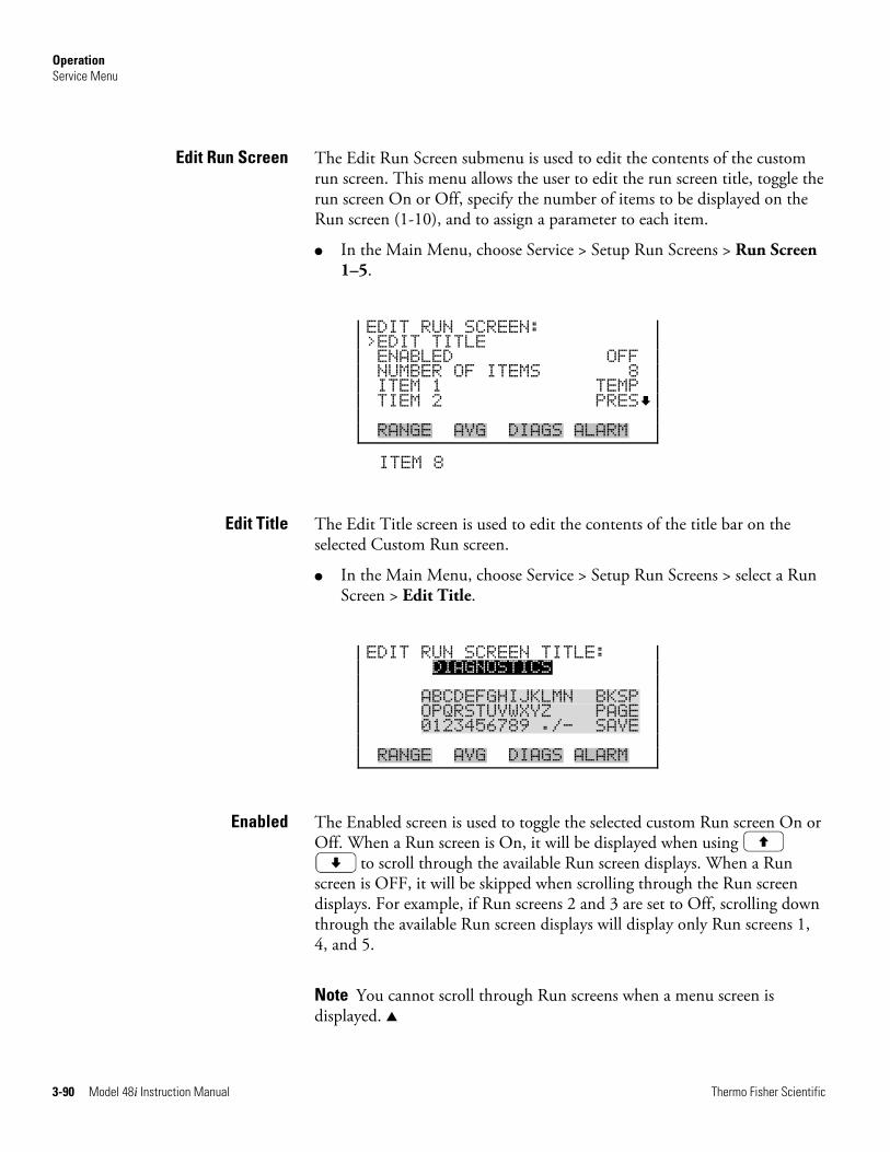
Operation Service Menu
3-90 Model 48i Instruction Manual Thermo Fisher Scientific
The Edit Run Screen submenu is used to edit the contents of the custom run screen. This menu allows the user to edit the run screen title, toggle the run screen On or Off, specify the number of items to be displayed on the Run screen (1-10), and to assign a parameter to each item.
● In the Main Menu, choose Service > Setup Run Screens > Run Screen 1–5.
EDIT RUN SCREEN: >EDIT TITLE ENABLED OFF NUMBER OF ITEMS 8 ITEM 1 TEMP TIEM 2 PRES RANGE AVG DIAGS ALARM
ITEM 8
The Edit Title screen is used to edit the contents of the title bar on the selected Custom Run screen.
● In the Main Menu, choose Service > Setup Run Screens > select a Run Screen > Edit Title.
EDIT RUN SCREEN TITLE: DIAGNOSTICS ABCDEFGHIJKLMN BKSP OPQRSTUVWXYZ PAGE 0123456789 ./- SAVE RANGE AVG DIAGS ALARM
The Enabled screen is used to toggle the selected custom Run screen On or Off. When a Run screen is On, it will be displayed when using
to scroll through the available Run screen displays. When a Run screen is OFF, it will be skipped when scrolling through the Run screen displays. For example, if Run screens 2 and 3 are set to Off, scrolling down through the available Run screen displays will display only Run screens 1, 4, and 5.
Note You cannot scroll through Run screens when a menu screen is displayed. ▲
Edit Run Screen
Edit Title
Enabled
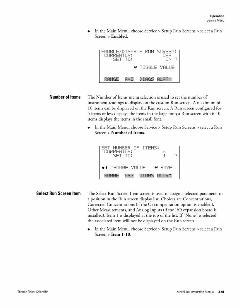
Operation Service Menu
Thermo Fisher Scientific Model 48i Instruction Manual 3-91
● In the Main Menu, choose Service > Setup Run Screens > select a Run Screen > Enabled.
ENABLE/DISABLE RUN SCREEN: CURRENTLY: OFF SET TO: ON ? TOGGLE VALUE RANGE AVG DIAGS ALARM
The Number of Items menu selection is used to set the number of instrument readings to display on the custom Run screen. A maximum of 10 items can be displayed on the Run screen. A Run screen configured for 5 items or less displays the items in the large font; a Run screen with 6-10 items displays the items in the small font.
● In the Main Menu, choose Service > Setup Run Screens > select a Run Screen > Number of Items.
SET NUMBER OF ITEMS: CURRENTLY: 5 SET TO: 4 ?
CHANGE VALUE SAVE RANGE AVG DIAGS ALARM
The Select Run Screen Item screen is used to assign a selected parameter to a position in the Run screen display list. Choices are Concentrations, Corrected Concentrations (if the O2 compensation option is enabled), Other Measurements, and Analog Inputs (if the I/O expansion board is installed). Item 1 is displayed at the top of the list. If “None” is selected, the associated item will not be displayed on the Run screen.
● In the Main Menu, choose Service > Setup Run Screens > select a Run Screen > Item 1-10.
Number of Items
Select Run Screen Item
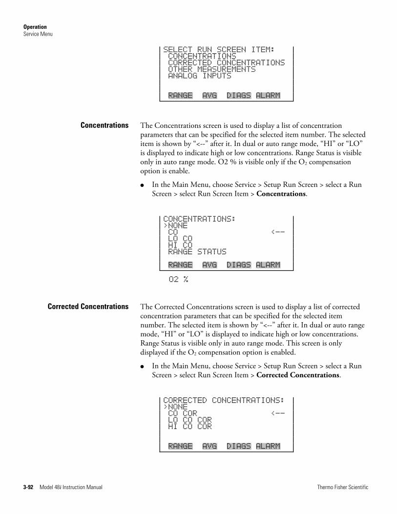
Operation Service Menu
3-92 Model 48i Instruction Manual Thermo Fisher Scientific
SELECT RUN SCREEN ITEM: CONCENTRATIONS CORRECTED CONCENTRATIONS OTHER MEASUREMENTS ANALOG INPUTS RANGE AVG DIAGS ALARM
The Concentrations screen is used to display a list of concentration parameters that can be specified for the selected item number. The selected item is shown by “<--” after it. In dual or auto range mode, “HI” or “LO” is displayed to indicate high or low concentrations. Range Status is visible only in auto range mode. O2 % is visible only if the O2 compensation option is enable.
● In the Main Menu, choose Service > Setup Run Screen > select a Run Screen > select Run Screen Item > Concentrations.
CONCENTRATIONS: >NONE CO <-- LO CO HI CO RANGE STATUS RANGE AVG DIAGS ALARM
O2 %
The Corrected Concentrations screen is used to display a list of corrected concentration parameters that can be specified for the selected item number. The selected item is shown by “<--” after it. In dual or auto range mode, “HI” or “LO” is displayed to indicate high or low concentrations. Range Status is visible only in auto range mode. This screen is only displayed if the O2 compensation option is enabled.
● In the Main Menu, choose Service > Setup Run Screen > select a Run Screen > select Run Screen Item > Corrected Concentrations.
CORRECTED CONCENTRATIONS: >NONE CO COR <-- LO CO COR HI CO COR RANGE AVG DIAGS ALARM
Concentrations
Corrected Concentrations
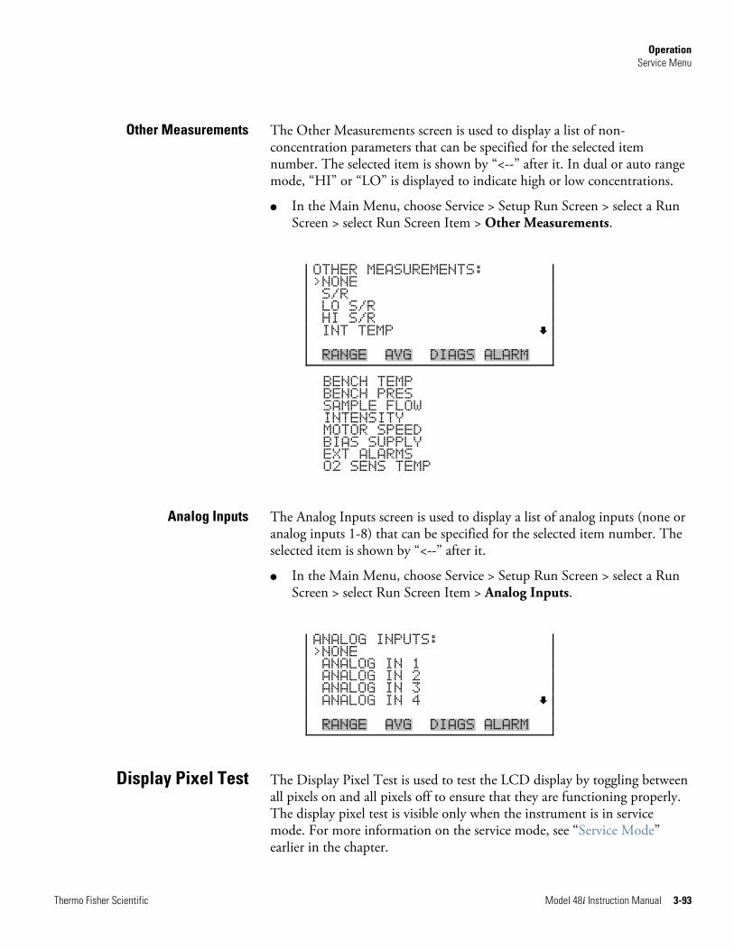
Operation Service Menu
Thermo Fisher Scientific Model 48i Instruction Manual 3-93
The Other Measurements screen is used to display a list of non-concentration parameters that can be specified for the selected item number. The selected item is shown by “<--” after it. In dual or auto range mode, “HI” or “LO” is displayed to indicate high or low concentrations.
● In the Main Menu, choose Service > Setup Run Screen > select a Run Screen > select Run Screen Item > Other Measurements.
OTHER MEASUREMENTS: >NONE S/R LO S/R HI S/R INT TEMP RANGE AVG DIAGS ALARM
BENCH TEMP BENCH PRES SAMPLE FLOW INTENSITY MOTOR SPEED BIAS SUPPLY EXT ALARMS O2 SENS TEMP
The Analog Inputs screen is used to display a list of analog inputs (none or analog inputs 1-8) that can be specified for the selected item number. The selected item is shown by “<--” after it.
● In the Main Menu, choose Service > Setup Run Screen > select a Run Screen > select Run Screen Item > Analog Inputs.
ANALOG INPUTS: >NONE ANALOG IN 1 ANALOG IN 2 ANALOG IN 3 ANALOG IN 4 RANGE AVG DIAGS ALARM
The Display Pixel Test is used to test the LCD display by toggling between all pixels on and all pixels off to ensure that they are functioning properly. The display pixel test is visible only when the instrument is in service mode. For more information on the service mode, see “Service Mode” earlier in the chapter.
Other Measurements
Analog Inputs
Display Pixel Test
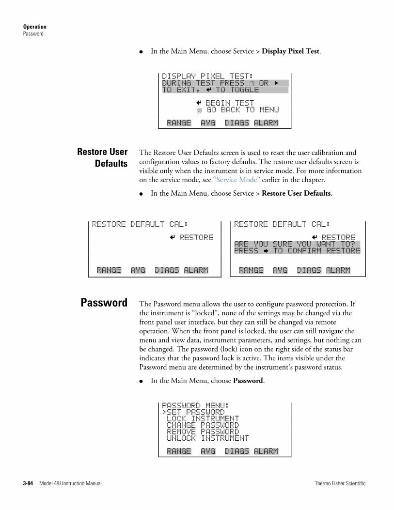
Operation Password
3-94 Model 48i Instruction Manual Thermo Fisher Scientific
● In the Main Menu, choose Service > Display Pixel Test.
DISPLAY PIXEL TEST: DURING TEST PRESS OR xx TO EXIT, TO TOGGLEXXXXXx BEGIN TEST GO BACK TO MENU RANGE AVG DIAGS ALARM
The Restore User Defaults screen is used to reset the user calibration and configuration values to factory defaults. The restore user defaults screen is visible only when the instrument is in service mode. For more information on the service mode, see “Service Mode” earlier in the chapter.
● In the Main Menu, choose Service > Restore User Defaults.
The Password menu allows the user to configure password protection. If the instrument is “locked”, none of the settings may be changed via the front panel user interface, but they can still be changed via remote operation. When the front panel is locked, the user can still navigate the menu and view data, instrument parameters, and settings, but nothing can be changed. The password (lock) icon on the right side of the status bar indicates that the password lock is active. The items visible under the Password menu are determined by the instrument’s password status.
● In the Main Menu, choose Password.
PASSWORD MENU: >SET PASSWORD LOCK INSTRUMENT CHANGE PASSWORD REMOVE PASSWORD UNLOCK INSTRUMENT RANGE AVG DIAGS ALARM
Restore User Defaults
Password
RESTORE DEFAULT CAL: RESTORE RANGE AVG DIAGS ALARM
RESTORE DEFAULT CAL: RESTORE ARE YOU SURE YOU WANT TO?x PRESS TO CONFIRM RESTORE RANGE AVG DIAGS ALARM
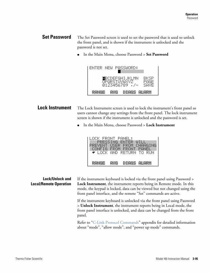
Operation Password
Thermo Fisher Scientific Model 48i Instruction Manual 3-95
The Set Password screen is used to set the password that is used to unlock the front panel, and is shown if the instrument is unlocked and the password is not set.
● In the Main Menu, choose Password > Set Password
ENTER NEW PASSWORD: RANGXXXXXE ABCDEFGHIJKLMN BKSP OPQRSTUVWXYZ PAGE 0123456789 ./- SAVE RANGE AVG DIAGS ALARM
The Lock Instrument screen is used to lock the instrument’s front panel so users cannot change any settings from the front panel. The lock instrument screen is shown if the instrument is unlocked and the password is set.
● In the Main Menu, choose Password > Lock Instrument
LOCK FRONT PANEL: XXXPRESSING ENTER WILLXXXX PREVENT USER FROM CHANGING XCONFIG FROM FRONT PANELXX LOCK AND RETURN TO RUN RANGE AVG DIAGS ALARM
If the instrument keyboard is locked via the front panel using Password > Lock Instrument, the instrument reports being in Remote mode. In this mode, the keypad is locked, data can be viewed but not changed using the front panel interface, and the remote “Set” commands are active.
If the instrument keyboard is unlocked via the front panel using Password > Unlock Instrument, the instrument reports being in Local mode, the front panel interface is unlocked, and data can be changed from the front panel.
Refer to “C-Link Protocol Commands” appendix for detailed information about “mode”, “allow mode”, and “power up mode” commands.
Set Password
Lock Instrument
Lock/Unlock and Local/Remote Operation
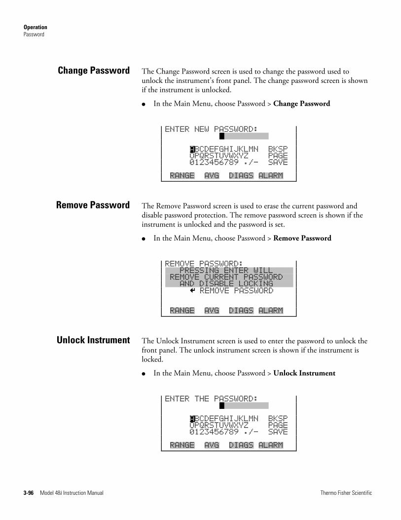
Operation Password
3-96 Model 48i Instruction Manual Thermo Fisher Scientific
The Change Password screen is used to change the password used to unlock the instrument’s front panel. The change password screen is shown if the instrument is unlocked.
● In the Main Menu, choose Password > Change Password
ENTER NEW PASSWORD: RANGXXXXXE ABCDEFGHIJKLMN BKSP OPQRSTUVWXYZ PAGE 0123456789 ./- SAVE RANGE AVG DIAGS ALARM
The Remove Password screen is used to erase the current password and disable password protection. The remove password screen is shown if the instrument is unlocked and the password is set.
● In the Main Menu, choose Password > Remove Password
REMOVE PASSWORD: XXXPRESSING ENTER WILLXXXX XREMOVE CURRENT PASSWORDXX XXXAND DISABLE LOCKINGXXXX REMOVE PASSWORD RANGE AVG DIAGS ALARM
The Unlock Instrument screen is used to enter the password to unlock the front panel. The unlock instrument screen is shown if the instrument is locked.
● In the Main Menu, choose Password > Unlock Instrument
ENTER THE PASSWORD: RANGXXXXXE ABCDEFGHIJKLMN BKSP OPQRSTUVWXYZ PAGE 0123456789 ./- SAVE RANGE AVG DIAGS ALARM
Change Password
Remove Password
Unlock Instrument
Thermo Fisher Scientific Model 48i Instruction Manual 4-1
Chapter 4 Calibration
This chapter describes the procedures for performing a standard zero/span calibration and a multipoint calibration of the Model 48i. The information described here is more than adequate to perform the calibration. However, if greater detail is needed, please refer to the Quality Assurance Handbook for Air Pollution Measurement Systems1.
The following sections discuss the required apparatus and procedure for calibrating the instrument.
The following equipment is required to calibrate the instrument:
A cylinder of CO in air containing an appropriate concentration of CO suitable for the selected operating range of the analyzer under calibration is necessary. The assay of the cylinder must be traceable either to a National Institute of Standards and Technology (NIST) CO in Air Standard Reference Material (SRM) or an NIST/EPA approved gas manufacturer's Certified Reference Material (CRM).
A recommended protocol for certifying CO gas cylinders against a CO, SRM or CRM is given in the Quality Assurance Handbook1. The CO gas cylinder should be recertified on a regular basis determined by the local quality control program.
Calibration requires zero air that is free of contaminants which will cause a detectable response on the CO analyzer. The zero air should contain <0.01 ppm CO. Since the Model 48i is virtually interference free, it is only necessary to ensure that CO has been removed.
It should be noted that zero air as supplied in cylinders from commercial suppliers typically contains CO concentrations in the 0.1-0.3 ppm range. So cylinder zero air should be scrubbed of the residual CO prior to its use in the Model 48i as a dilution gas or a zero standard. Room air which has been scrubbed of CO can also be used as the zero air source.
It is not necessary to remove SO2, NO, NO2, CO2, water vapor, or hydrocarbons, since the Model 48i does not respond to these molecules. If
Equipment Required
CO Concentration Standard
Zero Air Generator
Calibration Equipment Required
4-2 Model 48i Instruction Manual Thermo Fisher Scientific
water vapor is not removed, it might be necessary to correct the flow measurement data when calculating the dilution ratio of the span CO reference.
A platinum on alumina catalyst, operated at 250 °C, has been found to be a convenient oxidizer to convert CO to CO2.
If a zero air source is required, the following interferant removal methods are recommended:
● Compression
● Drying
● Oxidation
● Scrubbing
The zero air source should be at an elevated pressure to allow accurate and reproducible flow control and to aid in subsequent operations such as drying, oxidation, and scrubbing. An air compressor that gives an output of 10 psig is usually sufficient for most applications.
Several drying methods are available. Passing the compressed air through a bed of silica gel, using a heatless air dryer, or removing water vapor with a permeation dryer are three possible approaches.
The last step in the generation of the zero air is the removal of the remaining contaminants by either further reaction or absorption. Fixed bed reactors are usually employed.
In order to obtain an accurate dilution ratio in the dilution method used for calibration, the flow rates must be regulated to 1%, and be measured to an accuracy of at least 2%. The meter and controller can be two separate devices, or combined in one device. The user's manual for the meter should be consulted for calibration information.
Additional information on the calibration of flow devices can be found in the Quality Assurance Handbook1. It should be noted that all flows should be corrected to 25 °C and 760 mmHg, and that care should be exercised in correcting for water vapor content.
The regulator used must have a nonreactive diaphragm and internal parts, as well as a suitable delivery pressure.
Compression
Drying
Scrubbing
Flow Meter(s) and Controller(s)
Pressure Regulator for CO Standard Cylinder
Calibration Pre-Calibration
Thermo Fisher Scientific Model 48i Instruction Manual 4-3
A chamber constructed of glass, Teflon, or other nonreactive material, and designed to provide thorough mixing of CO and diluent air for the dilution method is required.
The output manifold should be constructed of glass, Teflon, or other nonreactive material, and should be of sufficient diameter to ensure an insignificant pressure drop at the analyzer connection. The system must have a vent designed to ensure atmospheric pressure at the manifold and to prevent ambient air from entering the manifold.
Prior to calibration, be sure the instrument is operating properly. Turn on the instrument and allow it to stabilize for one hour. Perform the service checks of the “Preventive Maintenance” chapter. Select the operating range and the averaging time of the Model 48i.
Note The averaging time should be less than the zero duration and less than the span duration. ▲
Note The calibration and calibration check duration times should be long enough to account for the transition (purge) process when switching from sample to zero and from zero to span. This transition time is the time required to purge the existing air. ▲
Note Depending on the plumbing configuration and the instrument, data from approximately the first minute of a zero calibration or check should be disregarded because of residual sample air. Also, data from approximately the first minute of a span calibration or check should be disregarded because the span is mixing with the residual zero air. ▲
Use the following procedure to calibrate the instrument.
Connect the instrument and the calibration equipment as shown in Figure 4–1. If an optional sample line filter is used, the calibration must be performed through this filter. Ensure that the flow rate into the output manifold is greater than the total flow required by the analyzer and any other flow demand connected to the manifold.
Mixing Chamber
Output Manifold
Pre-Calibration
Calibration
Connect the Instrument
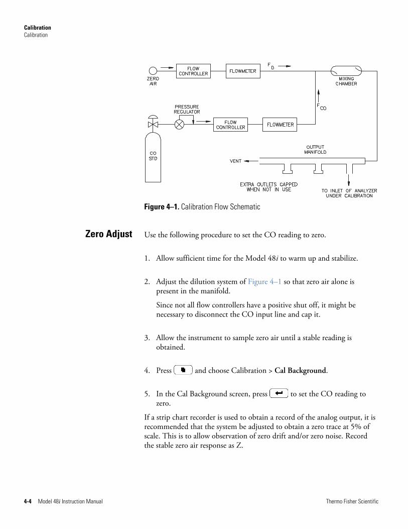
Calibration Calibration
4-4 Model 48i Instruction Manual Thermo Fisher Scientific
Figure 4–1. Calibration Flow Schematic
Use the following procedure to set the CO reading to zero.
1. Allow sufficient time for the Model 48i to warm up and stabilize.
2. Adjust the dilution system of Figure 4–1 so that zero air alone is present in the manifold.
Since not all flow controllers have a positive shut off, it might be necessary to disconnect the CO input line and cap it.
3. Allow the instrument to sample zero air until a stable reading is obtained.
4. Press and choose Calibration > Cal Background.
5. In the Cal Background screen, press to set the CO reading to zero.
If a strip chart recorder is used to obtain a record of the analog output, it is recommended that the system be adjusted to obtain a zero trace at 5% of scale. This is to allow observation of zero drift and/or zero noise. Record the stable zero air response as Z.
Zero Adjust
Calibration Calibration
Thermo Fisher Scientific Model 48i Instruction Manual 4-5
Use the following procedure to adjust the span.
1. Adjust the zero air flow and the CO flow from the standard CO cylinder to provide a diluted CO concentration of approximately 80% of the upper range limit (URL) of the analyzer.The total air flow must exceed the total demand of the analyzer connected to the output manifold to ensure that no ambient air is pulled into the manifold vent. The exact CO concentration is calculated from:
) F + F () F x ][CO (
= ][COCOD
COSTD OUT
Where:
[CO]OUT = diluted CO concentration at the output manifold, ppm
[CO]STD = concentration of the undiluted CO standard, ppm
FCO = flow rate of CO standard corrected to 25 °C and 760 mmHg, L/min
FD = flow rate of dilution air corrected to 25 °C and 760 mmHg, L/min
2. Allow the instrument to sample this CO concentration standard until a stable response is obtained.
3. From the Main Menu, choose Calibration > Cal Coef.
The first line of the display shows the current CO concentration reading. The second line of the display shows the CO range and the third line is where the CO concentration is entered.
4. Enter the CO calibration gas concentration using the pushbuttons, and then press to calibrate the CO reading to the CO calibration gas.
recorder response (percent scale) = (([CO]OUT x 100)/URL) + ZCO
Where:
URL = nominal upper range limit of the instrument operating range
ZCO = instrument response to zero air, %scale
5. Record the CO concentration and the instrument’s response.
Span Adjust
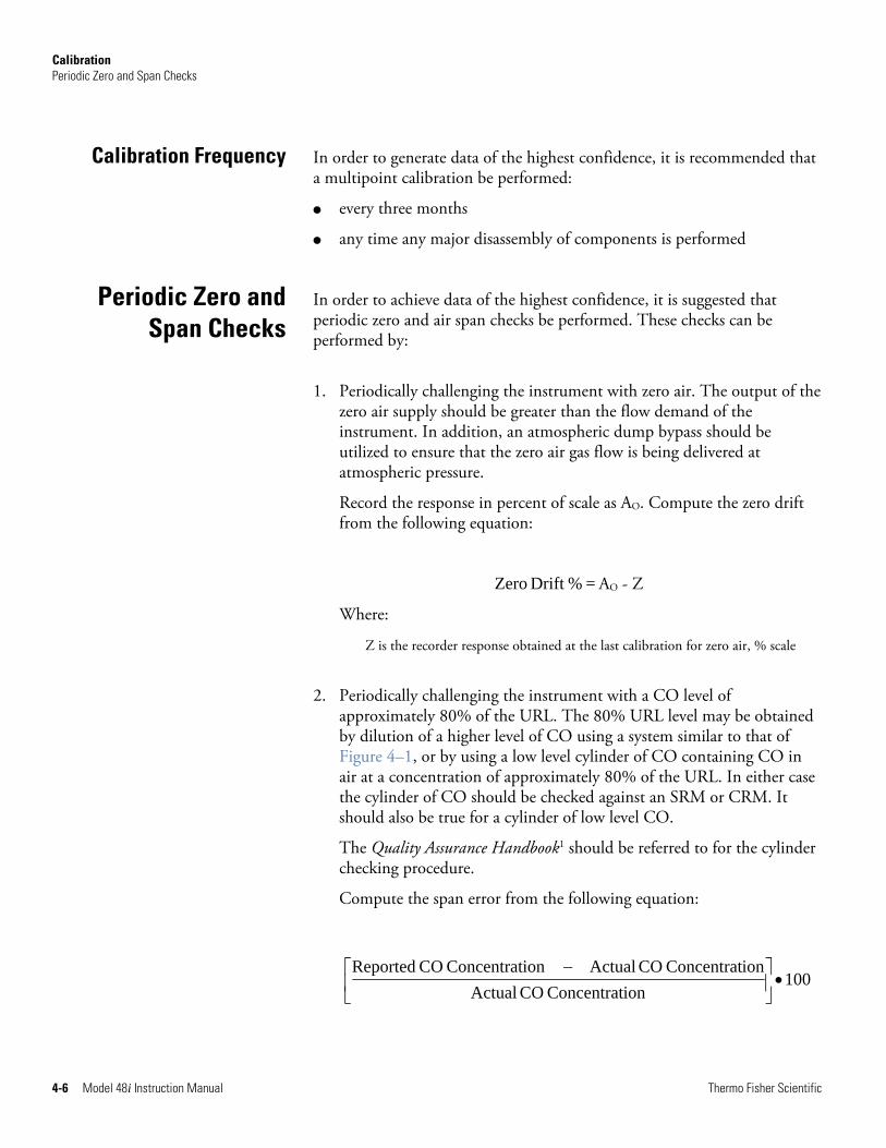
Calibration Periodic Zero and Span Checks
4-6 Model 48i Instruction Manual Thermo Fisher Scientific
In order to generate data of the highest confidence, it is recommended that a multipoint calibration be performed:
● every three months
● any time any major disassembly of components is performed
In order to achieve data of the highest confidence, it is suggested that periodic zero and air span checks be performed. These checks can be performed by:
1. Periodically challenging the instrument with zero air. The output of the zero air supply should be greater than the flow demand of the instrument. In addition, an atmospheric dump bypass should be utilized to ensure that the zero air gas flow is being delivered at atmospheric pressure.
Record the response in percent of scale as AO. Compute the zero drift from the following equation:
= %Drift Zero AO - Z
Where:
Z is the recorder response obtained at the last calibration for zero air, % scale
2. Periodically challenging the instrument with a CO level of approximately 80% of the URL. The 80% URL level may be obtained by dilution of a higher level of CO using a system similar to that of Figure 4–1, or by using a low level cylinder of CO containing CO in air at a concentration of approximately 80% of the URL. In either case the cylinder of CO should be checked against an SRM or CRM. It should also be true for a cylinder of low level CO.
The Quality Assurance Handbook1 should be referred to for the cylinder checking procedure.
Compute the span error from the following equation:
100
ionConcentrat CO ActualionConcentrat CO ActualionConcentrat CO Reported
•⎥⎦
⎤⎢⎣
⎡ −
Calibration Frequency
Periodic Zero andSpan Checks
Calibration HI and LO Multi-Point Calibration
Thermo Fisher Scientific Model 48i Instruction Manual 4-7
3. Latest copy of the Quality Assurance Handbook for Air Pollution Measurement Systems1 should be consulted to determine the level of acceptance of zero and span errors.
For detailed guidance in setting up a quality assurance program, refer to the Code of Federal Regulations and the EPA Handbook on Quality Assurance.
The instrument can also be calibrated using a dual three-point calibration. The calibration points are divided into a “low” range and a “high” range consisting of three points each:
● Cal point 1
● Cal point 2
● Cal point 3
The customer defines the ranges and Thermo Fisher Scientific recommends the following calibration points for each range:
● Cal point 1: 80% of range
● Cal point 2: 50% of range
● Cal point 3: 20% or range
Note If performing a multi-point calibration after a “bad” calibration or changing ranges it is recommended to start off with default values for the Cal point coefficients. ▲
To set default values, from the Main Menu select Service Mode > Hi Multi-Point Cal or Lo Multi-Point Cal. From Hi or Lo Multi-Point Cal, select Default Coef and press . The instrument will automatically reset the default values.
Use the following procedure to adjust cal points 1, 2, and 3.
1. Adjust the zero air flow and the CO flow from the standard CO cylinder to provide a diluted CO concentration of approximately 80% of the upper range limit (URL) of the instrument. The total air flow must exceed the total demand of the analyzer connected to the output manifold to ensure that no ambient air is pulled into the manifold vent. The exact CO concentration is calculated from:
HI and LO Multi-Point Calibration
Default Coefficients
Cal Point 1, 2, and 3 Adjust
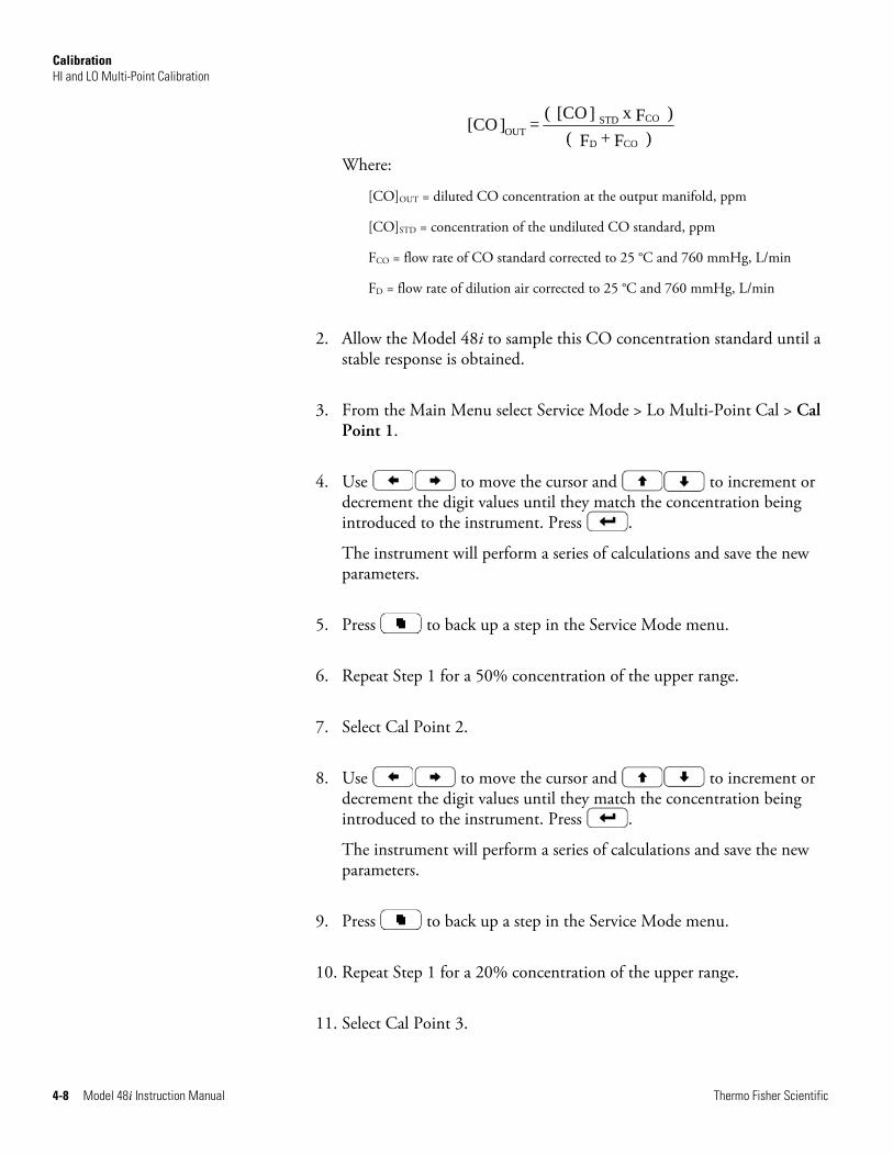
Calibration HI and LO Multi-Point Calibration
4-8 Model 48i Instruction Manual Thermo Fisher Scientific
) F + F () F x ][CO (
= ][COCOD
COSTD OUT
Where:
[CO]OUT = diluted CO concentration at the output manifold, ppm
[CO]STD = concentration of the undiluted CO standard, ppm
FCO = flow rate of CO standard corrected to 25 °C and 760 mmHg, L/min
FD = flow rate of dilution air corrected to 25 °C and 760 mmHg, L/min
2. Allow the Model 48i to sample this CO concentration standard until a stable response is obtained.
3. From the Main Menu select Service Mode > Lo Multi-Point Cal > Cal Point 1.
4. Use to move the cursor and to increment or decrement the digit values until they match the concentration being introduced to the instrument. Press .
The instrument will perform a series of calculations and save the new parameters.
5. Press to back up a step in the Service Mode menu.
6. Repeat Step 1 for a 50% concentration of the upper range.
7. Select Cal Point 2.
8. Use to move the cursor and to increment or decrement the digit values until they match the concentration being introduced to the instrument. Press .
The instrument will perform a series of calculations and save the new parameters.
9. Press to back up a step in the Service Mode menu.
10. Repeat Step 1 for a 20% concentration of the upper range.
11. Select Cal Point 3.
Calibration References
Thermo Fisher Scientific Model 48i Instruction Manual 4-9
12. Use to move the cursor and to increment or decrement the digit values until they match the concentration being introduced to the instrument. Press .
The instrument will perform a series of calculations and save the new parameters.
13. Press to back up a step in the Service Mode menu.
14. Select Coefficients and press .
The instrument will automatically calculate the new coefficients and save the new parameters.
15. Repeat Steps 1 through 12 for Hi Multi-Point Cal.
1. Section 12 of EPA-454/R-98-004, Quality Assurance Handbook for Air Pollution Measurement Systems, Volume II, Part 1, August 1998, available at www.epa.gov/ttn/amtic/qabook.html, and 40 CFR 50, Appendix C “Measurement Principle and Calibration Procedure for the Measurement of Carbon Monoxide in the Atmosphere (Non-Dispersive Infrared Photometry)”.
Section 12 also provides information on “Calibration of Primary and Secondary Standards for Flow Measurements”.
Specific information on certification of concentration standards is given in EPA-600/R93/224, EPA Traceability Protocol for Assay and Certification of Gaseous Calibration Standards, 1993 Available from www.NTIS.gov (PB94130424).
References

Thermo Fisher Scientific Model 48i Instruction Manual 5-1
Chapter 5 Preventive Maintenance
This chapter describes the periodic maintenance procedures that should be performed on the instrument to ensure proper operation.
Since usage and environmental conditions vary greatly, you should inspect the components frequently until an appropriate maintenance schedule is determined. This includes the sample pump, solenoid valves, and IR source, which have a limited life.
Other operations such as cleaning the optics and checking the calibration of the pressure and temperature transducers should be performed on a regular basis.
This chapter includes the following maintenance information and replacement procedures:
● “Safety Precautions” on page 5-1
● “Replacement Parts” on page 5-2
● “Cleaning the Outside Case” on page 5-2
● “Cleaning the Optics” on page 5-2
● “IR Source Replacement” on page 5-3
● “Fan Filter Inspection and Cleaning” on page 5-3
● “Leak Test and Pump Check Out” on page 5-4
● “Pump Rebuilding” on page 5-5
Read the safety precautions before beginning any procedures in this chapter.
WARNING If the equipment is operated in a manner not specified by the manufacturer, the protection provided by the equipment may be impaired. ▲
Safety Precautions
Preventive Maintenance Replacement Parts
5-2 Model 48i Instruction Manual Thermo Fisher Scientific
Equipment Damage Some internal components can be damaged by small amounts of static electricity. A properly grounded antistatic wrist strap must be worn while handling any internal component. For more information about appropriate safety precautions, see the “Servicing” chapter. ▲
See the “Servicing” chapter for a list of replacement parts and the associated replacement procedures.
WARNING If the equipment is operated in a manner not specified by the manufacturer, the protection provided by the equipment may be impaired. ▲
Clean the outside case using a damp cloth being careful not to damage the labels on the case.
Equipment Damage Do not use solvents or other cleaning products to clean the outside case. ▲
Best results are obtained when the optics are cleaned prior to calibration. The cleanliness of the mirrors should be checked any time the AGC intensity is below 200,000 Hz, since one cause of low output is light attenuation due to dirt on the mirrors.
Equipment Damage Some internal components can be damaged by small amounts of static electricity. A properly grounded antistatic wrist strap must be worn while handling any internal component. For more information about appropriate safety precautions, see the “Servicing” chapter. ▲
Use the following procedure to clean the mirrors.
1. Turn off power and disconnect power line.
2. Remove the field mirror by removing the four Allen head screws holding it to the main bench (use a 9/64-inch Allen wrench).
Replacement Parts
Cleaning the Outside Case
Cleaning the Optics
Preventive Maintenance IR Source Replacement
Thermo Fisher Scientific Model 48i Instruction Manual 5-3
3. Carefully clean each mirror using a cotton swab and methanol. Rinse with distilled or deionized water. Dry by blowing clean dry air over the mirror.
4. Reassemble following the above procedure in reverse. It is not necessary to realign any mirror following cleaning.
5. Calibrate the instrument. See the “Calibration” chapter in this manual.
The IR source control system has been designed to operate the wire wound resistor IR source conservatively in order to increase its life. Nevertheless, the IR source does have a finite life. Since the IR source is relatively inexpensive and easily replaced, it is recommended that the IR source be replaced after one year of continuous use. This will prevent loss of data due to IR source failure. If an IR source is to be replaced on an as needed basis, it should be replaced when:
● There is no light output
● After cleaning the optics, the IR light intensities remain below 100,000 Hz
It is not necessary to recalibrate the Model 48i after replacing the IR source since it is a ratio instrument, and replacing the IR source does not affect the calibration.
Use the following procedure to inspect and clean the fan filter (Figure 5–1).
1. Remove the fan guard from the fan and remove the filter.
2. Flush the filter with warm water and let dry (a clean, oil-free purge will help the drying process) or blow the filter clean with compressed air.
3. Re-install the filter and fan guard.
IR Source Replacement
Fan Filter Inspection and Cleaning
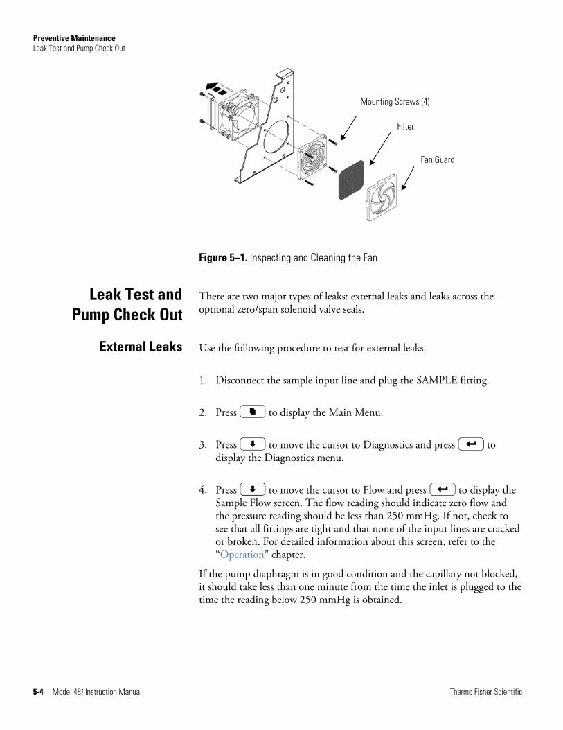
Preventive Maintenance Leak Test and Pump Check Out
5-4 Model 48i Instruction Manual Thermo Fisher Scientific
Figure 5–1. Inspecting and Cleaning the Fan
There are two major types of leaks: external leaks and leaks across the optional zero/span solenoid valve seals.
Use the following procedure to test for external leaks.
1. Disconnect the sample input line and plug the SAMPLE fitting.
2. Press to display the Main Menu.
3. Press to move the cursor to Diagnostics and press to display the Diagnostics menu.
4. Press to move the cursor to Flow and press to display the Sample Flow screen. The flow reading should indicate zero flow and the pressure reading should be less than 250 mmHg. If not, check to see that all fittings are tight and that none of the input lines are cracked or broken. For detailed information about this screen, refer to the “Operation” chapter.
If the pump diaphragm is in good condition and the capillary not blocked, it should take less than one minute from the time the inlet is plugged to the time the reading below 250 mmHg is obtained.
Leak Test and Pump Check Out
External Leaks
Mounting Screws (4)
Filter
Fan Guard
Preventive Maintenance Pump Rebuilding
Thermo Fisher Scientific Model 48i Instruction Manual 5-5
In order to check for leaks across the optional valves, plug the SPAN inlet line, press until span appears in the status line and follow the “External Leaks” procedure.
If the pressure drops below 250 mmHg the valve associated with the span line is functioning normally. Repeat for the valve associated with the zero line by plugging the zero inlet, press until zero appears in the status line and follow the “External Leaks” procedure.
If the pressure drops below 250 mmHg, the valve associated with the zero line is functioning normally.
For new technology pump, use the following procedure to rebuild the pump (Figure 5–2). The new technology pump will have the repair kit part number on its label. If no repair kit part number is listed, refer to the procedure for the older model pump following this procedure. To replace the pump, see “Pump Replacement” on page 7-20.
Equipment Required:
Flatblade screwdriver
Pump rebuild kit (flapper valve and diaphragm)
Equipment Damage Some internal components can be damaged by small amounts of static electricity. A properly grounded antistatic wrist strap must be worn while handling any internal component. ▲
1. Turn instrument OFF, unplug the power cord, and remove the cover. Make a sketch of the position of any tubes and fittings for ease of re-assembly later.
2. Mark the position of the pump top plate, bottom plate and compressor housing relative to each other by drawing a line on the edges with a pencil or marker to ensure proper re-assembly.
3. The aluminum compressor housing cover must be removed to gain access to the inside compressor housing. Remove the four screws and then remove the cover. Re-use any gasketing. Remove any debris that may have accumulated in the bottom of the compressor housing.
Leaks Across the Optional Zero/Span and Sample
Solenoid Valves
Pump Rebuilding
Disassembly
Preventive Maintenance Pump Rebuilding
5-6 Model 48i Instruction Manual Thermo Fisher Scientific
4. Remove the four top plate screws and remove the top plate. Note the positioning of the flapper valve relative to the valve ports on the top plate and bottom plate. Lift off the flapper valve.
5. Remove the bottom plate.
6. Check that all parts are clean from dirt and clean as necessary. DO NOT scratch the parts.
7. Removal of the old diaphragm: Rotate the fan so that the diaphragm is positioned at the top dead center. This will help unseat the edge of the diaphragm. If required, push up from underneath the diaphragm or use a non-metallic tool to pry up the diaphragm from the housing groove. Unscrew the old diaphragm by turning it counterclockwise using both hands. DO NOT use tools!
Note Take care not to lose the shim rings positioned between the diaphragm support cup and connecting rod, as the same shim rings must be used during re-assembly. ▲
While unscrewing the diaphragm with one hand, use your other hand to secure the support cup and shim ring(s) onto the diaphragm stud. Lift the diaphragm, support cup and shim ring(s) from the pump.
The compressor housing cover must be removed to gain access to and secure the support cup and shim ring(s) onto the stud. Note that the quantity and thickness of the shim ring(s) will vary from pump to pump. Parts removed must be replaced exactly as found. If repairing multiple pumps, take care not to mix the parts.
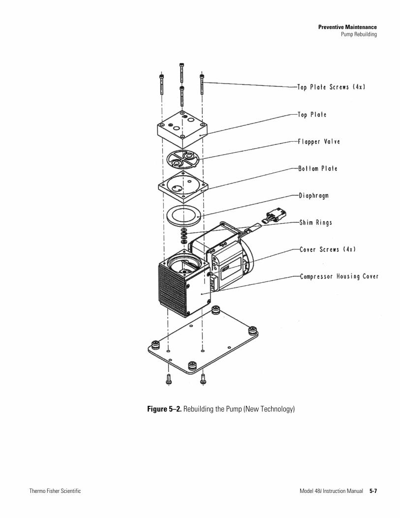
Preventive Maintenance Pump Rebuilding
Thermo Fisher Scientific Model 48i Instruction Manual 5-7
Figure 5–2. Rebuilding the Pump (New Technology)

Preventive Maintenance Pump Rebuilding
5-8 Model 48i Instruction Manual Thermo Fisher Scientific
1. Place the parts removed in the previous step onto the threaded stud of the new diaphragm. Carefully screw the new diaphragm into the connecting rod. Secure the support cup and small parts onto the diaphragm stud using a technique similar to that used during removal. It is helpful to hold the connecting rod at a slight angle until the threads are started. Spin the diaphragm on until it is snug, then lift and grip the edges of the diaphragm at 7 and 2 o’clock and tighten firmly using both hands. DO NOT use tools!
Tip: If the pump is loose and not mounted, position and hold the pump with the motor shaft vertical when starting the threaded diaphragm stud into the connecting rod. This helps to prevent the small parts from falling off the stud.
2. Turn the fan until the diaphragm is flat across (mid-point of the stroke). With the diaphragm centered over the compressor housing, firmly seat the diaphragm edge into the compressor housing groove.
3. Place the clean bottom plate onto the compressor housing using the reference mark made earlier to ensure the correct orientation. Then place the new flapper on top of the intermediate plate.
4. Place the clean top plate on top of the bottom plate using the reference mark made earlier to ensure the correct orientation. Tighten the four top plate screws snugly in a diagonal pattern and then tighten to a maximum torque of 6-7 inch-lbs. Turn the fan by hand to confirm that the pump turns freely.
5. Replace the compressor housing cover and gasket. Install the four cover screws. No not over-tighten.
Assembly with New Diaphragm and Valve
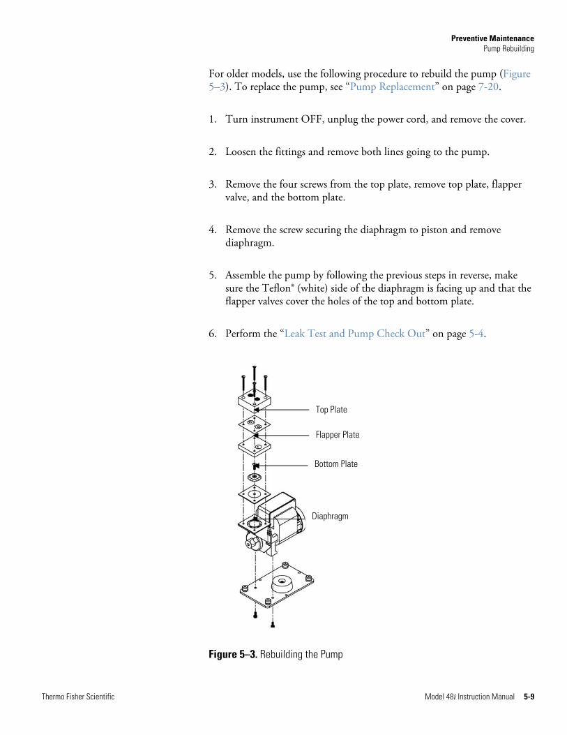
Preventive Maintenance Pump Rebuilding
Thermo Fisher Scientific Model 48i Instruction Manual 5-9
For older models, use the following procedure to rebuild the pump (Figure 5–3). To replace the pump, see “Pump Replacement” on page 7-20.
1. Turn instrument OFF, unplug the power cord, and remove the cover.
2. Loosen the fittings and remove both lines going to the pump.
3. Remove the four screws from the top plate, remove top plate, flapper valve, and the bottom plate.
4. Remove the screw securing the diaphragm to piston and remove diaphragm.
5. Assemble the pump by following the previous steps in reverse, make sure the Teflon® (white) side of the diaphragm is facing up and that the flapper valves cover the holes of the top and bottom plate.
6. Perform the “Leak Test and Pump Check Out” on page 5-4.
Figure 5–3. Rebuilding the Pump
Top Plate
Flapper Plate
Bottom Plate
Diaphragm

Thermo Fisher Scientific Model 48i Instruction Manual 6-1
Chapter 6 Troubleshooting
This instrument has been designed to achieve a high level of reliability. In the event of problems or failure, the troubleshooting guidelines, board-level connection diagrams, connector pin descriptions, and testing procedures presented in this chapter should be helpful in isolating and identifying problems.
For additional fault location information refer to the “Preventive Maintenance” chapter in this manual.
The service mode in the “Operation” chapter includes parameters and functions that are useful when making adjustments or diagnosing problems.
The Technical Support Department at Thermo Fisher Scientific can also be consulted in the event of problems. See “Service Locations” on page 6-20 for contact information. In any correspondence with the factory, please note both the serial number and program number of the instrument.
This chapter provides the following troubleshooting and service support information:
● “Safety Precautions” on page 6-1
● “Troubleshooting Guides” on page 6-1
● “Board-Level Connection Diagrams” on page 6-5
● “Connector Pin Descriptions” on page 6-7
● “Service Locations” on page 6-20
Read the safety precautions in the Preface and “Servicing” chapter before performing any actions listed in this chapter.
The troubleshooting guides presented in this chapter are designed to help isolate and identify instrument problems.
Table 6–1 provides general troubleshooting information and indicates the checks that you should perform if you experience an instrument problem.
Safety Precautions
Troubleshooting Guides
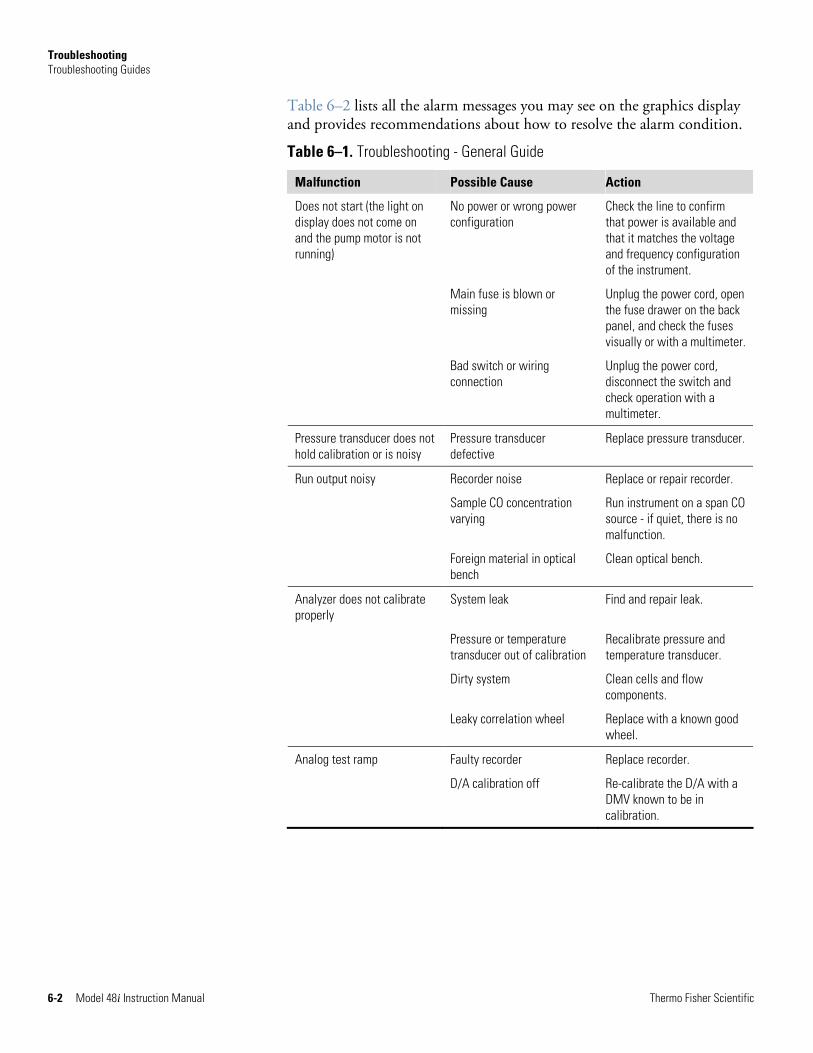
Troubleshooting Troubleshooting Guides
6-2 Model 48i Instruction Manual Thermo Fisher Scientific
Table 6–2 lists all the alarm messages you may see on the graphics display and provides recommendations about how to resolve the alarm condition.
Table 6–1. Troubleshooting - General Guide
Malfunction Possible Cause Action
Does not start (the light on display does not come on and the pump motor is not running)
No power or wrong power configuration
Check the line to confirm that power is available and that it matches the voltage and frequency configuration of the instrument.
Main fuse is blown or missing
Unplug the power cord, open the fuse drawer on the back panel, and check the fuses visually or with a multimeter.
Bad switch or wiring connection
Unplug the power cord, disconnect the switch and check operation with a multimeter.
Pressure transducer does not hold calibration or is noisy
Pressure transducer defective
Replace pressure transducer.
Run output noisy Recorder noise Replace or repair recorder.
Sample CO concentration varying
Run instrument on a span CO source - if quiet, there is no malfunction.
Foreign material in optical bench
Clean optical bench.
Analyzer does not calibrate properly
System leak Find and repair leak.
Pressure or temperature transducer out of calibration
Recalibrate pressure and temperature transducer.
Dirty system Clean cells and flow components.
Leaky correlation wheel Replace with a known good wheel.
Analog test ramp Faulty recorder Replace recorder.
D/A calibration off Re-calibrate the D/A with a DMV known to be in calibration.
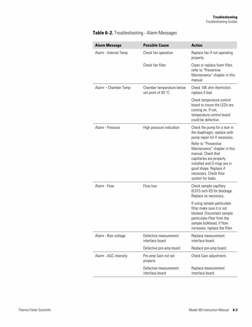
Troubleshooting Troubleshooting Guides
Thermo Fisher Scientific Model 48i Instruction Manual 6-3
Table 6–2. Troubleshooting - Alarm Messages
Alarm Message Possible Cause Action
Alarm - Internal Temp Check fan operation Replace fan if not operating properly.
Check fan filter Clean or replace foam filter, refer to “Preventive Maintenance” chapter in this manual.
Alarm – Chamber Temp Chamber temperature below set point of 50 °C
Check 10K ohm thermistor, replace if bad.
Check temperature control board to insure the LEDs are coming on. If not, temperature control board could be defective.
Alarm - Pressure High pressure indication Check the pump for a tear in the diaphragm, replace with pump repair kit if necessary.
Refer to “Preventive Maintenance” chapter in this manual. Check that capillaries are properly installed and O-rings are in good shape. Replace if necessary. Check flow system for leaks.
Alarm - Flow Flow low Check sample capillary (0.015 inch ID) for blockage. Replace as necessary.
If using sample particulate filter make sure it is not blocked. Disconnect sample particulate filter from the sample bulkhead, if flow increases, replace the filter.
Alarm - Bias voltage Defective measurement interface board
Replace measurement interface board.
Defective pre-amp board Replace pre-amp board.
Alarm - AGC intensity Pre-amp Gain not set properly
Check Gain adjustment.
Defective measurement interface board
Replace measurement interface board.
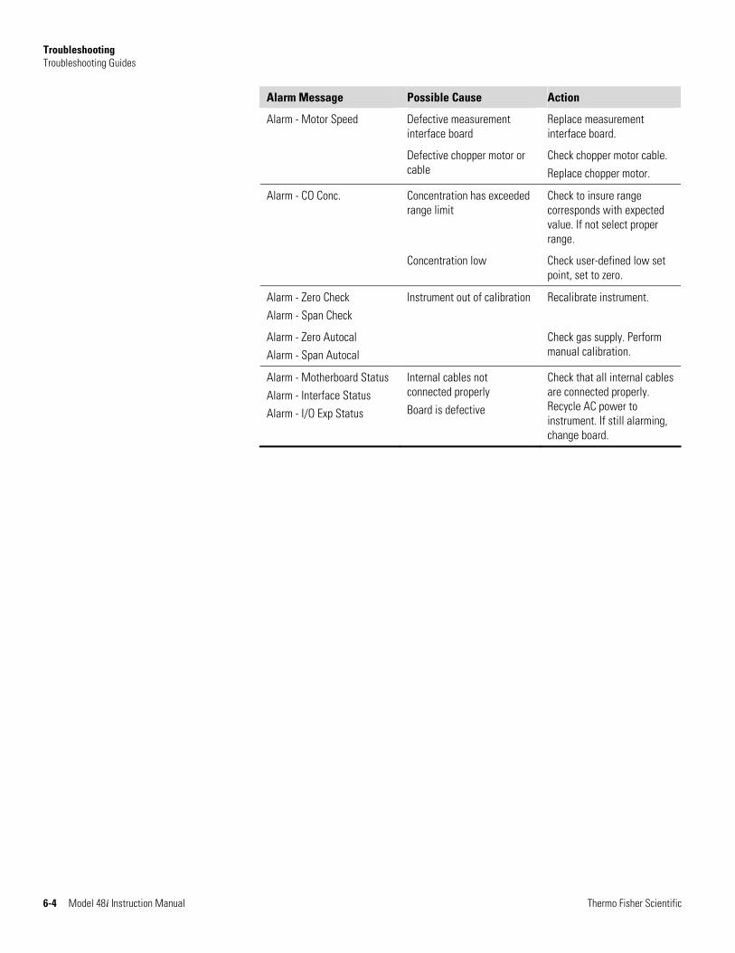
Troubleshooting Troubleshooting Guides
6-4 Model 48i Instruction Manual Thermo Fisher Scientific
Alarm Message Possible Cause Action
Alarm - Motor Speed Defective measurement interface board
Replace measurement interface board.
Defective chopper motor or cable
Check chopper motor cable. Replace chopper motor.
Alarm - CO Conc. Concentration has exceeded range limit
Check to insure range corresponds with expected value. If not select proper range.
Concentration low Check user-defined low set point, set to zero.
Alarm - Zero Check Alarm - Span Check
Instrument out of calibration Recalibrate instrument.
Alarm - Zero Autocal Alarm - Span Autocal
Check gas supply. Perform manual calibration.
Alarm - Motherboard Status Alarm - Interface Status Alarm - I/O Exp Status
Internal cables not connected properly Board is defective
Check that all internal cables are connected properly. Recycle AC power to instrument. If still alarming, change board.
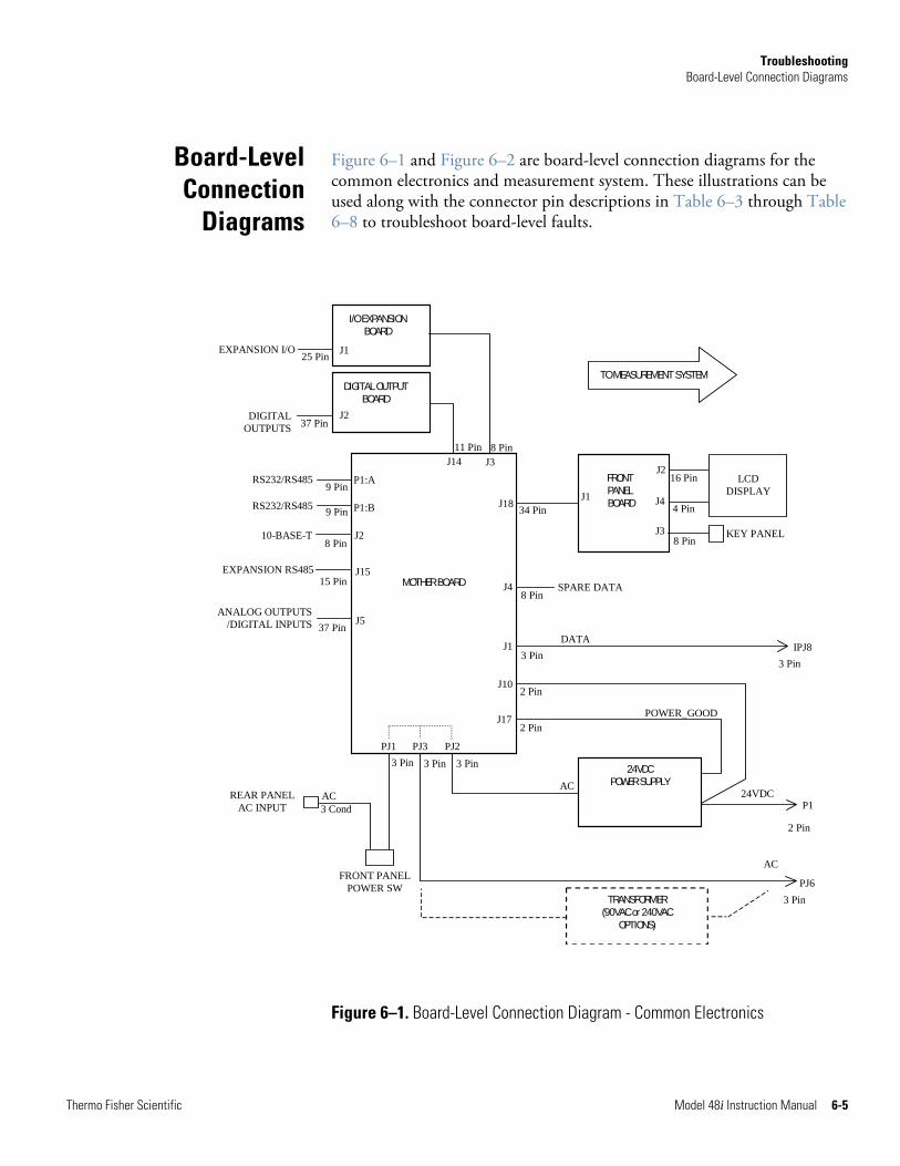
Troubleshooting Board-Level Connection Diagrams
Thermo Fisher Scientific Model 48i Instruction Manual 6-5
Figure 6–1 and Figure 6–2 are board-level connection diagrams for the common electronics and measurement system. These illustrations can be used along with the connector pin descriptions in Table 6–3 through Table 6–8 to troubleshoot board-level faults.
Figure 6–1. Board-Level Connection Diagram - Common Electronics
Board-Level Connection
Diagrams
2 Pin
P1
DIGITALOUTPUTS
24VDC POWER SUPPLY
MOTHER BOARD
DIGITAL OUTPUT BOARD
I/O EXPANSION BOARD
J14 J3FRONT PANEL BOARD J1
LCD DISPLAY
KEY PANEL
J18
J2
J4
J3
J1
J10
J17
PJ1 PJ3 PJ2
FRONT PANELPOWER SW
16 Pin
4 Pin
8 Pin
34 Pin
3 Pin
2 Pin
3 Pin 3 Pin 3 Pin
PJ63 Pin
IPJ83 Pin
8 Pin 11 Pin
2 Pin
EXPANSION RS485
ANALOG OUTPUTS/DIGITAL INPUTS
P1:A
P1:B
RS232/RS485
J2 10-BASE-T
J15
J5
15 Pin
8 Pin
37 Pin
9 Pin
9 Pin RS232/RS485
J1 EXPANSION I/O
J2
25 Pin
37 Pin
AC
ACREAR PANEL
AC INPUT 3 Cond AC
POWER_GOOD
24VDC
TRANSFORMER (90VAC or 240VAC
OPTIONS)
J48 Pin
SPARE DATA
DATA
TO MEASUREMENT SYSTEM
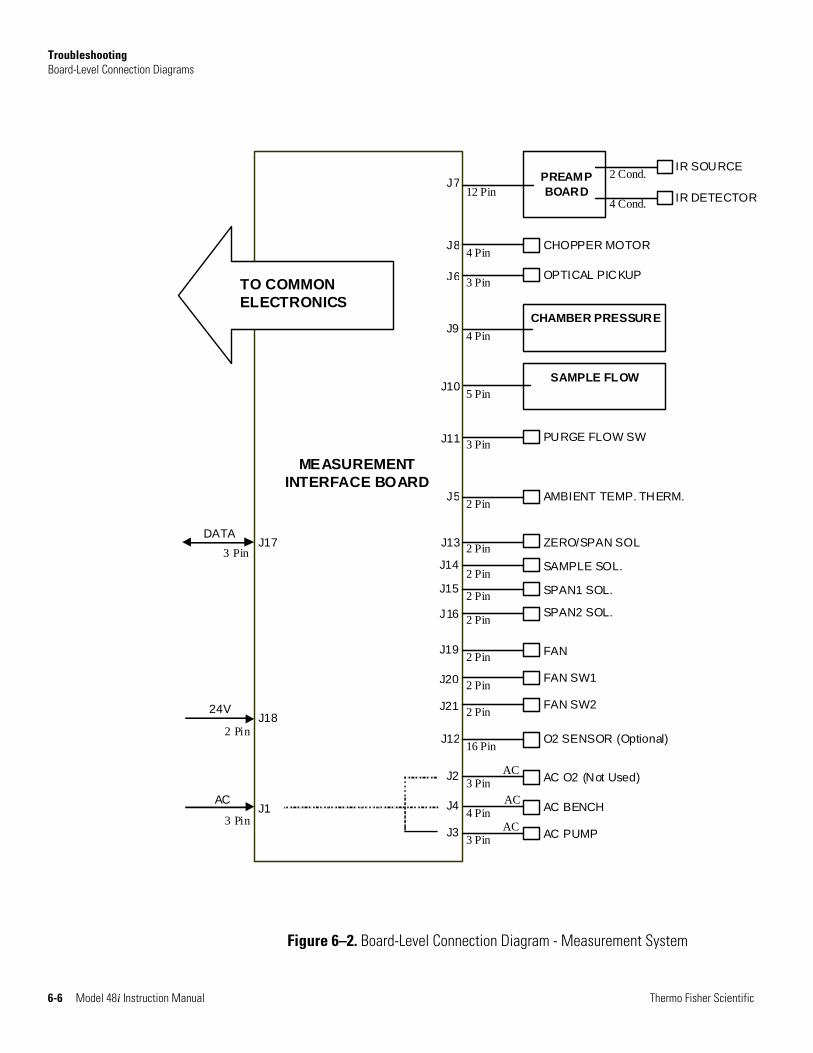
Troubleshooting Board-Level Connection Diagrams
6-6 Model 48i Instruction Manual Thermo Fisher Scientific
MEASUREMENTINTERFACE BOARD
J17
J1 3 Pin
2 Pin
3 Pin
AC
DATA
24V J18
TO COMMONELECTRONICS
AC PUMP 3 PinJ3 ACAC BENCH 4 PinJ4 AC
SPAN1 SOL. 2 Pin
2 PinJ16 SPAN2 SOL.
SAMPLE SOL. 2 PinJ15
J142 Pin ZERO/SPAN SOL J13
FAN2 PinJ19
2 PinJ20 FAN SW1
2 PinJ21 FAN SW2
3 Pin PURGE FLOW SW J11
4 Pin CHOPPER MOTOR J8
O2 SENSOR (Optional) 16 PinJ12
AMBIENT TEMP. THERM.2 PinJ5
3 Pin OPTICAL PICKUP J6
4 PinCHAMBER PRESSURE
5 PinSAMPLE FLOW
J9
J10
PREAMP BOARD 12 Pin
J7
4 Cond. IR DETECTOR
2 Cond. IR SOURCE
AC O2 (Not Used) 3 PinJ2 AC
Figure 6–2. Board-Level Connection Diagram - Measurement System
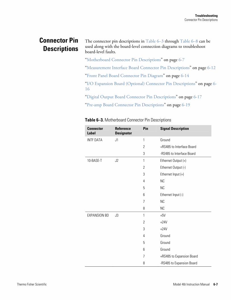
Troubleshooting Connector Pin Descriptions
Thermo Fisher Scientific Model 48i Instruction Manual 6-7
The connector pin descriptions in Table 6–3 through Table 6–8 can be used along with the board-level connection diagrams to troubleshoot board-level faults.
“Motherboard Connector Pin Descriptions” on page 6-7
“Measurement Interface Board Connector Pin Descriptions” on page 6-12
“Front Panel Board Connector Pin Diagram” on page 6-14
“I/O Expansion Board (Optional) Connector Pin Descriptions” on page 6-16
“Digital Output Board Connector Pin Descriptions” on page 6-17
“Pre-amp Board Connector Pin Descriptions” on page 6-19
Table 6–3. Motherboard Connector Pin Descriptions
Connector Label
Reference Designator
Pin Signal Description
INTF DATA J1 1 Ground
2 +RS485 to Interface Board
3 -RS485 to Interface Board
10-BASE-T J2 1 Ethernet Output (+)
2 Ethernet Output (-)
3 Ethernet Input (+)
4 NC
5 NC
6 Ethernet Input (-)
7 NC
8 NC
EXPANSION BD J3 1 +5V
2 +24V
3 +24V
4 Ground
5 Ground
6 Ground
7 +RS485 to Expansion Board
8 -RS485 to Expansion Board
Connector Pin Descriptions
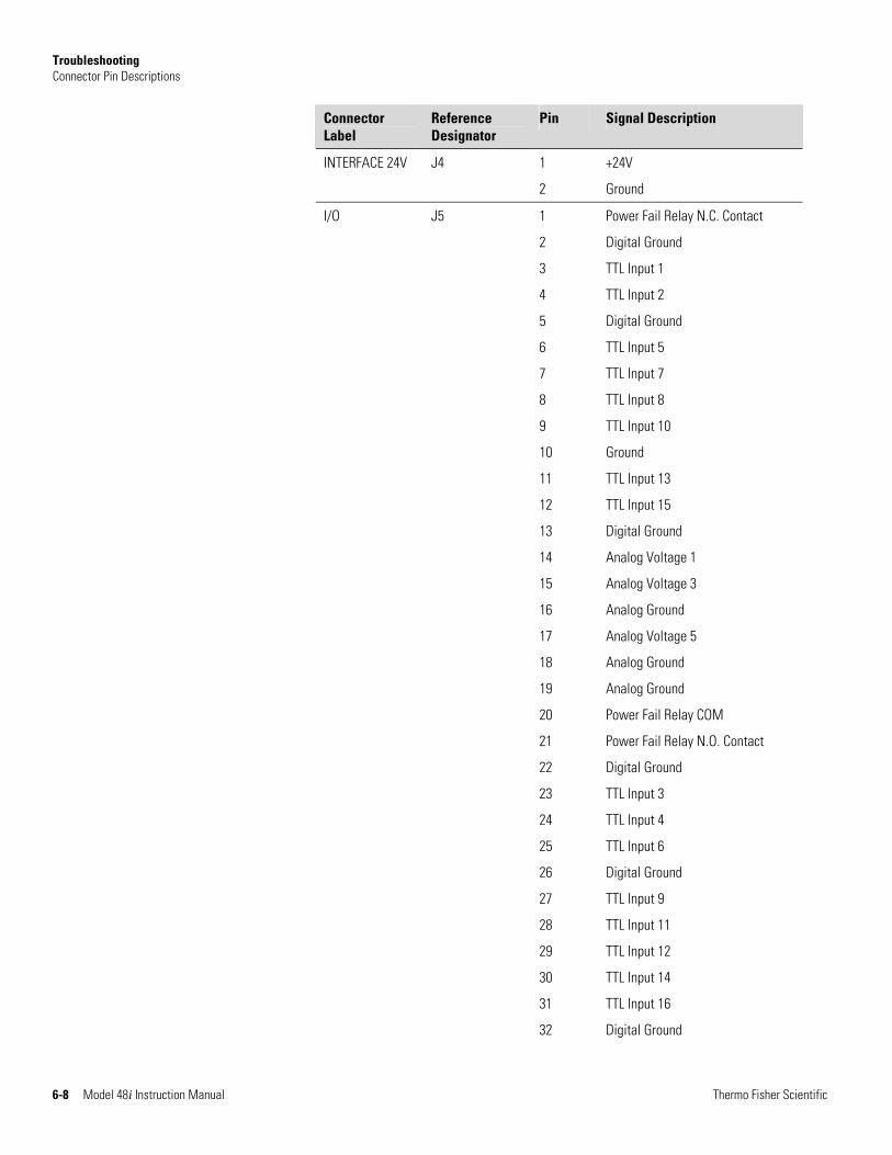
Troubleshooting Connector Pin Descriptions
6-8 Model 48i Instruction Manual Thermo Fisher Scientific
Connector Label
Reference Designator
Pin Signal Description
INTERFACE 24V J4 1 +24V
2 Ground
I/O J5 1 Power Fail Relay N.C. Contact
2 Digital Ground
3 TTL Input 1
4 TTL Input 2
5 Digital Ground
6 TTL Input 5
7 TTL Input 7
8 TTL Input 8
9 TTL Input 10
10 Ground
11 TTL Input 13
12 TTL Input 15
13 Digital Ground
14 Analog Voltage 1
15 Analog Voltage 3
16 Analog Ground
17 Analog Voltage 5
18 Analog Ground
19 Analog Ground
20 Power Fail Relay COM
21 Power Fail Relay N.O. Contact
22 Digital Ground
23 TTL Input 3
24 TTL Input 4
25 TTL Input 6
26 Digital Ground
27 TTL Input 9
28 TTL Input 11
29 TTL Input 12
30 TTL Input 14
31 TTL Input 16
32 Digital Ground
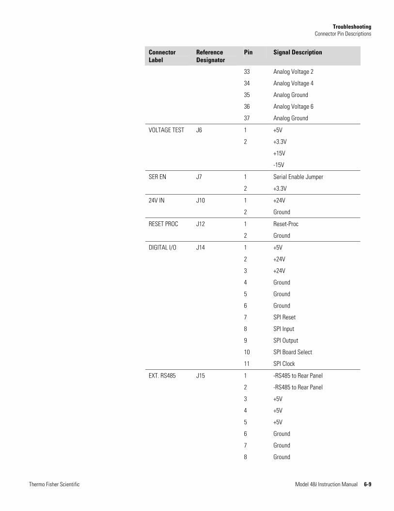
Troubleshooting Connector Pin Descriptions
Thermo Fisher Scientific Model 48i Instruction Manual 6-9
Connector Label
Reference Designator
Pin Signal Description
33 Analog Voltage 2
34 Analog Voltage 4
35 Analog Ground
36 Analog Voltage 6
37 Analog Ground
VOLTAGE TEST J6 1 +5V
2 +3.3V
+15V
-15V
SER EN J7 1 Serial Enable Jumper
2 +3.3V
24V IN J10 1 +24V
2 Ground
RESET PROC J12 1 Reset-Proc
2 Ground
DIGITAL I/O J14 1 +5V
2 +24V
3 +24V
4 Ground
5 Ground
6 Ground
7 SPI Reset
8 SPI Input
9 SPI Output
10 SPI Board Select
11 SPI Clock
EXT. RS485 J15 1 -RS485 to Rear Panel
2 -RS485 to Rear Panel
3 +5V
4 +5V
5 +5V
6 Ground
7 Ground
8 Ground
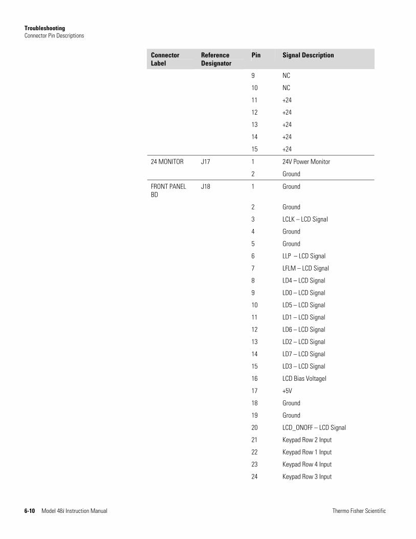
Troubleshooting Connector Pin Descriptions
6-10 Model 48i Instruction Manual Thermo Fisher Scientific
Connector Label
Reference Designator
Pin Signal Description
9 NC
10 NC
11 +24
12 +24
13 +24
14 +24
15 +24
24 MONITOR J17 1 24V Power Monitor
2 Ground
FRONT PANEL BD
J18 1 Ground
2 Ground
3 LCLK – LCD Signal
4 Ground
5 Ground
6 LLP – LCD Signal
7 LFLM – LCD Signal
8 LD4 – LCD Signal
9 LD0 – LCD Signal
10 LD5 – LCD Signal
11 LD1 – LCD Signal
12 LD6 – LCD Signal
13 LD2 – LCD Signal
14 LD7 – LCD Signal
15 LD3 – LCD Signal
16 LCD Bias Voltagel
17 +5V
18 Ground
19 Ground
20 LCD_ONOFF – LCD Signal
21 Keypad Row 2 Input
22 Keypad Row 1 Input
23 Keypad Row 4 Input
24 Keypad Row 3 Input
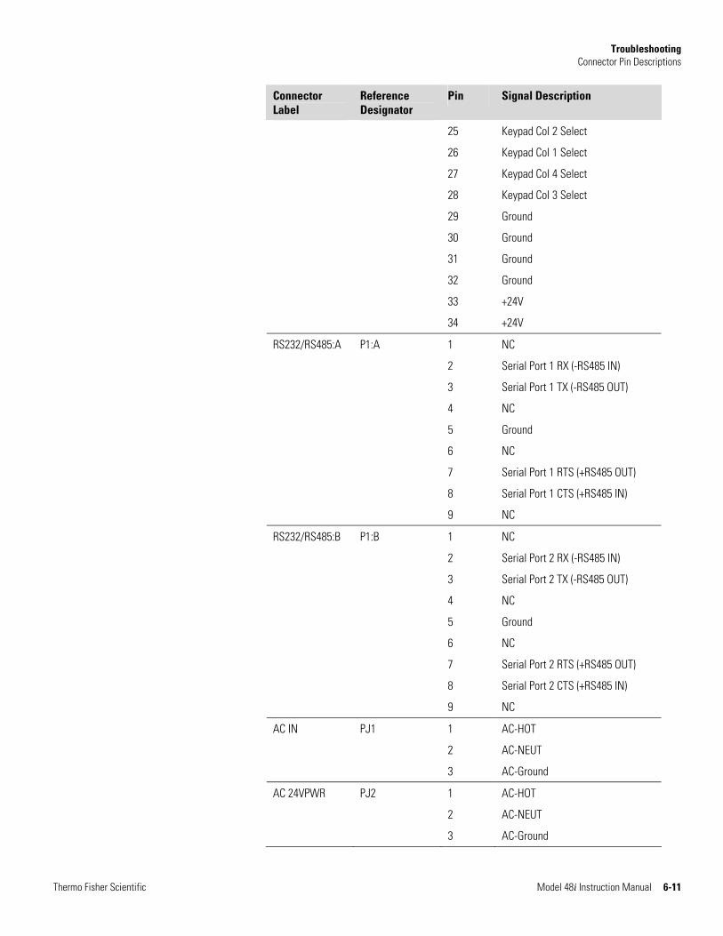
Troubleshooting Connector Pin Descriptions
Thermo Fisher Scientific Model 48i Instruction Manual 6-11
Connector Label
Reference Designator
Pin Signal Description
25 Keypad Col 2 Select
26 Keypad Col 1 Select
27 Keypad Col 4 Select
28 Keypad Col 3 Select
29 Ground
30 Ground
31 Ground
32 Ground
33 +24V
34 +24V
RS232/RS485:A P1:A 1 NC
2 Serial Port 1 RX (-RS485 IN)
3 Serial Port 1 TX (-RS485 OUT)
4 NC
5 Ground
6 NC
7 Serial Port 1 RTS (+RS485 OUT)
8 Serial Port 1 CTS (+RS485 IN)
9 NC
RS232/RS485:B P1:B 1 NC
2 Serial Port 2 RX (-RS485 IN)
3 Serial Port 2 TX (-RS485 OUT)
4 NC
5 Ground
6 NC
7 Serial Port 2 RTS (+RS485 OUT)
8 Serial Port 2 CTS (+RS485 IN)
9 NC
AC IN PJ1 1 AC-HOT
2 AC-NEUT
3 AC-Ground
AC 24VPWR PJ2 1 AC-HOT
2 AC-NEUT
3 AC-Ground
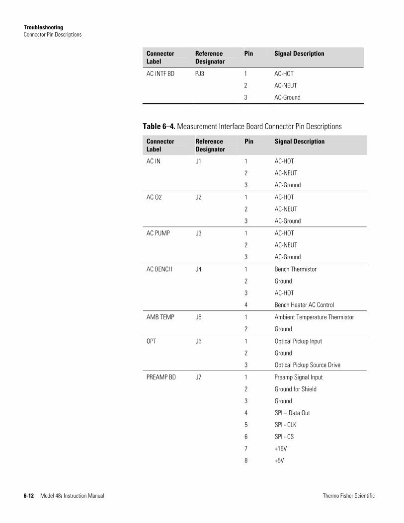
Troubleshooting Connector Pin Descriptions
6-12 Model 48i Instruction Manual Thermo Fisher Scientific
Connector Label
Reference Designator
Pin Signal Description
AC INTF BD PJ3 1 AC-HOT
2 AC-NEUT
3 AC-Ground
Table 6–4. Measurement Interface Board Connector Pin Descriptions
Connector Label
Reference Designator
Pin Signal Description
AC IN J1 1 AC-HOT
2 AC-NEUT
3 AC-Ground
AC O2 J2 1 AC-HOT
2 AC-NEUT
3 AC-Ground
AC PUMP J3 1 AC-HOT
2 AC-NEUT
3 AC-Ground
AC BENCH J4 1 Bench Thermistor
2 Ground
3 AC-HOT
4 Bench Heater AC Control
AMB TEMP J5 1 Ambient Temperature Thermistor
2 Ground
OPT J6 1 Optical Pickup Input
2 Ground
3 Optical Pickup Source Drive
PREAMP BD J7 1 Preamp Signal Input
2 Ground for Shield
3 Ground
4 SPI – Data Out
5 SPI - CLK
6 SPI - CS
7 +15V
8 +5V
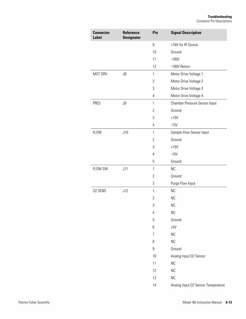
Troubleshooting Connector Pin Descriptions
Thermo Fisher Scientific Model 48i Instruction Manual 6-13
Connector Label
Reference Designator
Pin Signal Description
9 +18V for IR Source
10 Ground
11 -100V
12 -100V Return
MOT DRV J8 1 Motor Drive Voltage 1
2 Motor Drive Voltage 2
3 Motor Drive Voltage 3
4 Motor Drive Voltage 4
PRES J9 1 Chamber Pressure Sensor Input
2 Ground
3 +15V
4 -15V
FLOW J10 1 Sample Flow Sensor Input
2 Ground
3 +15V
4 -15V
5 Ground
FLOW SW J11 1 NC
2 Ground
3 Purge Flow Input
O2 SENS J12 1 NC
2 NC
3 NC
4 NC
5 Ground
6 +5V
7 NC
8 NC
9 Ground
10 Analog Input O2 Sensor
11 NC
12 NC
13 NC
14 Analog Input O2 Sensor Temperature
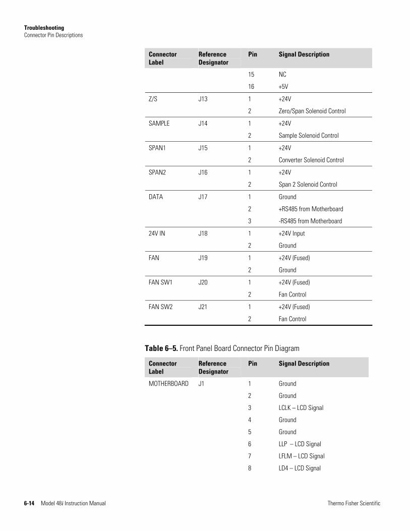
Troubleshooting Connector Pin Descriptions
6-14 Model 48i Instruction Manual Thermo Fisher Scientific
Connector Label
Reference Designator
Pin Signal Description
15 NC
16 +5V
Z/S J13 1 +24V
2 Zero/Span Solenoid Control
SAMPLE J14 1 +24V
2 Sample Solenoid Control
SPAN1 J15 1 +24V
2 Converter Solenoid Control
SPAN2 J16 1 +24V
2 Span 2 Solenoid Control
DATA J17 1 Ground
2 +RS485 from Motherboard
3 -RS485 from Motherboard
24V IN J18 1 +24V Input
2 Ground
FAN J19 1 +24V (Fused)
2 Ground
FAN SW1 J20 1 +24V (Fused)
2 Fan Control
FAN SW2 J21 1 +24V (Fused)
2 Fan Control
Table 6–5. Front Panel Board Connector Pin Diagram
Connector Label
Reference Designator
Pin Signal Description
MOTHERBOARD J1 1 Ground
2 Ground
3 LCLK – LCD Signal
4 Ground
5 Ground
6 LLP – LCD Signal
7 LFLM – LCD Signal
8 LD4 – LCD Signal
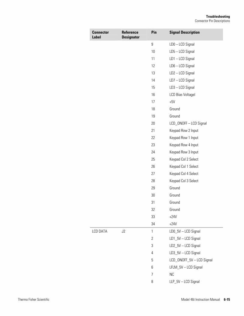
Troubleshooting Connector Pin Descriptions
Thermo Fisher Scientific Model 48i Instruction Manual 6-15
Connector Label
Reference Designator
Pin Signal Description
9 LD0 – LCD Signal
10 LD5 – LCD Signal
11 LD1 – LCD Signal
12 LD6 – LCD Signal
13 LD2 – LCD Signal
14 LD7 – LCD Signal
15 LD3 – LCD Signal
16 LCD Bias Voltagel
17 +5V
18 Ground
19 Ground
20 LCD_ONOFF – LCD Signal
21 Keypad Row 2 Input
22 Keypad Row 1 Input
23 Keypad Row 4 Input
24 Keypad Row 3 Input
25 Keypad Col 2 Select
26 Keypad Col 1 Select
27 Keypad Col 4 Select
28 Keypad Col 3 Select
29 Ground
30 Ground
31 Ground
32 Ground
33 +24V
34 +24V
LCD DATA J2 1 LD0_5V – LCD Signal
2 LD1_5V – LCD Signal
3 LD2_5V – LCD Signal
4 LD3_5V – LCD Signal
5 LCD_ONOFF_5V – LCD Signal
6 LFLM_5V – LCD Signal
7 NC
8 LLP_5V – LCD Signal
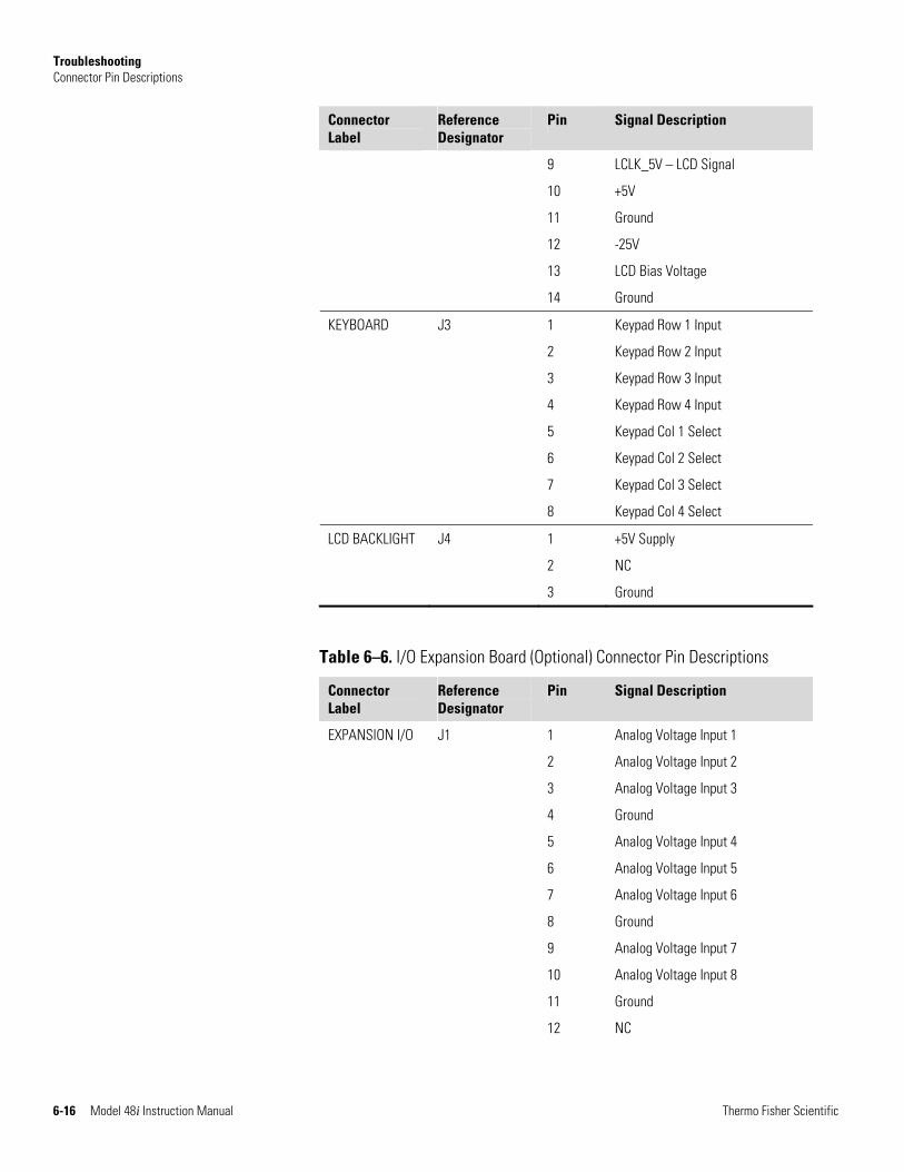
Troubleshooting Connector Pin Descriptions
6-16 Model 48i Instruction Manual Thermo Fisher Scientific
Connector Label
Reference Designator
Pin Signal Description
9 LCLK_5V – LCD Signal
10 +5V
11 Ground
12 -25V
13 LCD Bias Voltage
14 Ground
KEYBOARD J3 1 Keypad Row 1 Input
2 Keypad Row 2 Input
3 Keypad Row 3 Input
4 Keypad Row 4 Input
5 Keypad Col 1 Select
6 Keypad Col 2 Select
7 Keypad Col 3 Select
8 Keypad Col 4 Select
LCD BACKLIGHT J4 1 +5V Supply
2 NC
3 Ground
Table 6–6. I/O Expansion Board (Optional) Connector Pin Descriptions
Connector Label
Reference Designator
Pin Signal Description
EXPANSION I/O J1 1 Analog Voltage Input 1
2 Analog Voltage Input 2
3 Analog Voltage Input 3
4 Ground
5 Analog Voltage Input 4
6 Analog Voltage Input 5
7 Analog Voltage Input 6
8 Ground
9 Analog Voltage Input 7
10 Analog Voltage Input 8
11 Ground
12 NC
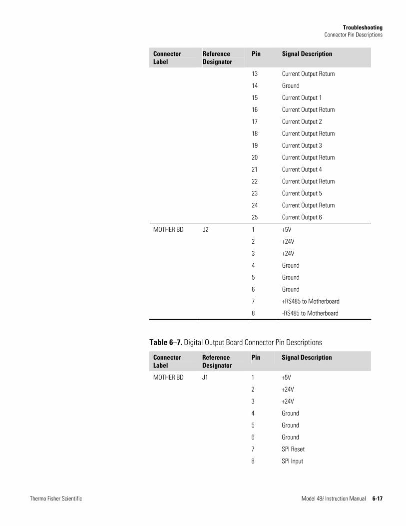
Troubleshooting Connector Pin Descriptions
Thermo Fisher Scientific Model 48i Instruction Manual 6-17
Connector Label
Reference Designator
Pin Signal Description
13 Current Output Return
14 Ground
15 Current Output 1
16 Current Output Return
17 Current Output 2
18 Current Output Return
19 Current Output 3
20 Current Output Return
21 Current Output 4
22 Current Output Return
23 Current Output 5
24 Current Output Return
25 Current Output 6
MOTHER BD J2 1 +5V
2 +24V
3 +24V
4 Ground
5 Ground
6 Ground
7 +RS485 to Motherboard
8 -RS485 to Motherboard
Table 6–7. Digital Output Board Connector Pin Descriptions
Connector Label
Reference Designator
Pin Signal Description
MOTHER BD J1 1 +5V
2 +24V
3 +24V
4 Ground
5 Ground
6 Ground
7 SPI Reset
8 SPI Input
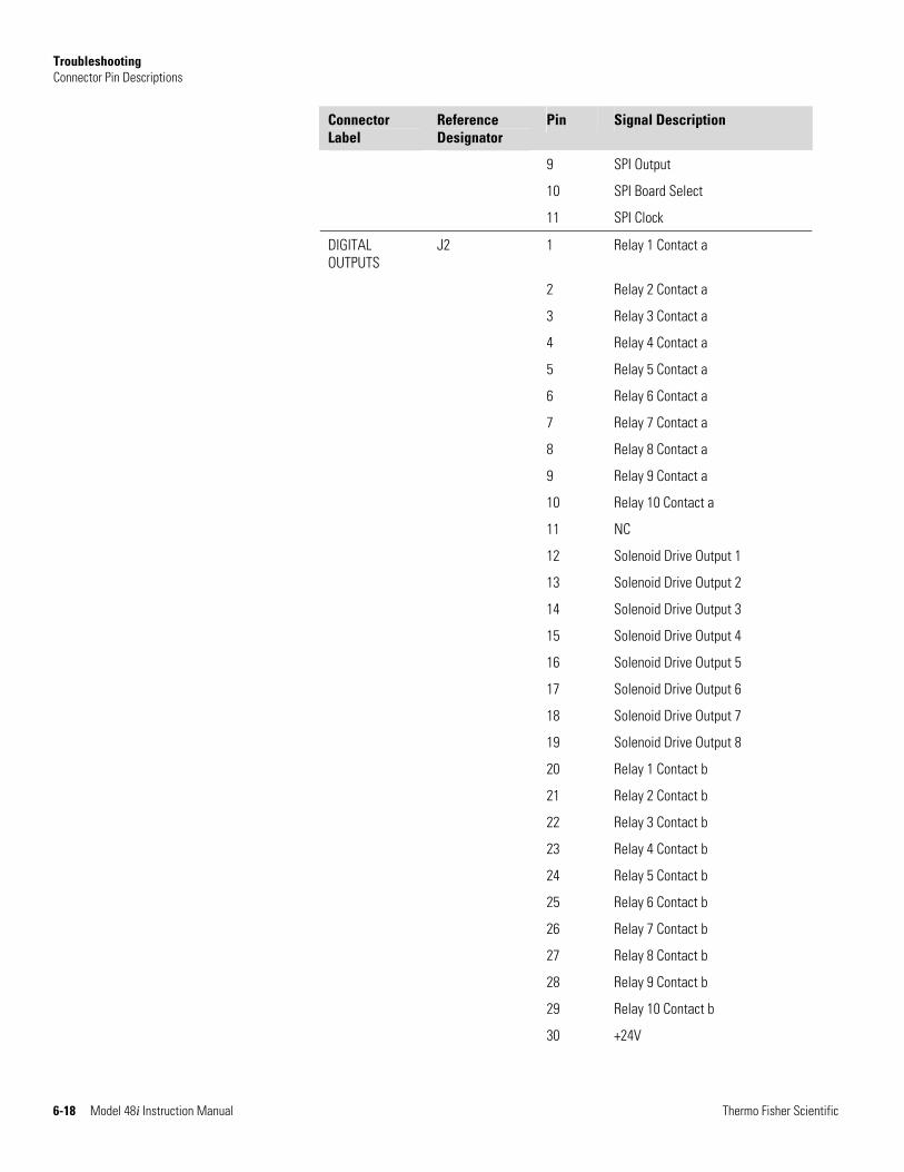
Troubleshooting Connector Pin Descriptions
6-18 Model 48i Instruction Manual Thermo Fisher Scientific
Connector Label
Reference Designator
Pin Signal Description
9 SPI Output
10 SPI Board Select
11 SPI Clock
DIGITAL OUTPUTS
J2 1 Relay 1 Contact a
2 Relay 2 Contact a
3 Relay 3 Contact a
4 Relay 4 Contact a
5 Relay 5 Contact a
6 Relay 6 Contact a
7 Relay 7 Contact a
8 Relay 8 Contact a
9 Relay 9 Contact a
10 Relay 10 Contact a
11 NC
12 Solenoid Drive Output 1
13 Solenoid Drive Output 2
14 Solenoid Drive Output 3
15 Solenoid Drive Output 4
16 Solenoid Drive Output 5
17 Solenoid Drive Output 6
18 Solenoid Drive Output 7
19 Solenoid Drive Output 8
20 Relay 1 Contact b
21 Relay 2 Contact b
22 Relay 3 Contact b
23 Relay 4 Contact b
24 Relay 5 Contact b
25 Relay 6 Contact b
26 Relay 7 Contact b
27 Relay 8 Contact b
28 Relay 9 Contact b
29 Relay 10 Contact b
30 +24V
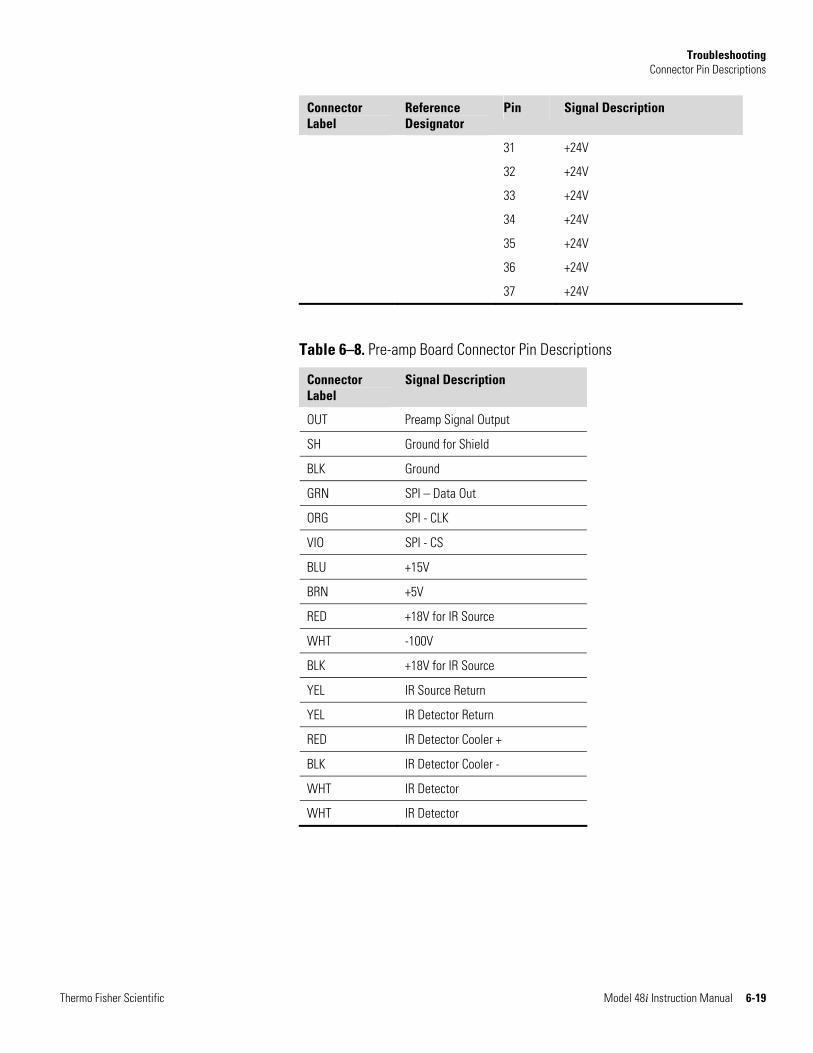
Troubleshooting Connector Pin Descriptions
Thermo Fisher Scientific Model 48i Instruction Manual 6-19
Connector Label
Reference Designator
Pin Signal Description
31 +24V
32 +24V
33 +24V
34 +24V
35 +24V
36 +24V
37 +24V
Table 6–8. Pre-amp Board Connector Pin Descriptions
Connector Label
Signal Description
OUT Preamp Signal Output
SH Ground for Shield
BLK Ground
GRN SPI – Data Out
ORG SPI - CLK
VIO SPI - CS
BLU +15V
BRN +5V
RED +18V for IR Source
WHT -100V
BLK +18V for IR Source
YEL IR Source Return
YEL IR Detector Return
RED IR Detector Cooler +
BLK IR Detector Cooler -
WHT IR Detector
WHT IR Detector
Troubleshooting Service Locations
6-20 Model 48i Instruction Manual Thermo Fisher Scientific
For additional assistance, service is available from exclusive distributors worldwide. Contact one of the phone numbers below for product support and technical information or visit us on the web at www.thermo.com/aqi.
1-866-282-0430 Toll Free
1-508-520-0430 International
Service Locations
Thermo Fisher Scientific Model 48i Instruction Manual 7-1
Chapter 7 Servicing
This chapter explains how to replace the Model 48i subassemblies. It assumes that a subassembly has been identified as defective and needs to be replaced (or is an “expendable” item, not covered under warranty. Expendable items are indicated with an asterisk (*) in the “Model 48i Replacement Parts” table.
For fault location information refer to the “Preventive Maintenance” chapter and the “Troubleshooting” chapter in this manual.
The service mode described in the “Operation” chapter also includes parameters and functions that are useful when making adjustments or diagnosing problems.
For additional service assistance, see “Service Locations” on page 7-41.
This chapter includes the following parts information and component replacement procedures:
● “Safety Precautions” on page 7-3
● “Firmware Updates” on page 7-4
● “Accessing the Service Mode” on page 7-4
● “Replacement Parts List” on page 5-2
● “Cable List” on page 7-6
● “External Device Connection Components” on page 7-6
● “Removing the Measurement Case Assembly and Lowering the Partition Panel” on page 7-8
● “Fuse Replacement” on page 7-8
● “Fan/Filter Replacement” on page 7-10
● “IR Source Replacement” on page 7-11
● “Filter Wheel Replacement” on page 7-12
● “Chopper Motor Replacement” on page 7-14
● “Optical Bench Replacement” on page 7-15
● “Optical Switch Replacement” on page 7-16
Servicing Service Locations
7-2 Model 48i Instruction Manual Thermo Fisher Scientific
● “Bench Heater Assembly Replacement” on page 7-17
● “Detector/Preamplifier Assembly Replacement” on page 7-18
● “Preamp Board Calibration” on page 7-20
● “Pump Replacement” on page 7-20
● “Pressure Transducer Replacement” on page 7-21
● “Pressure Transducer Calibration” on page 7-22
● “Flow Transducer Replacement” on page 7-25
● “Flow Transducer Calibration” on page 7-25
● “Capillary Cleaning or Replacement” on page 7-26
● “Optional Zero/Span and Sample Solenoid Valve Replacement” on page 7-27
● “Analog Output Testing” on page 7-28
● “Analog Output Calibration” on page 7-30
● “Analog Input Calibration” on page 7-31
● “Ambient Temperature Calibration” on page 7-33
● “I/O Expansion Board (Optional) Replacement” on page 7-34
● “Internal O2 Sensor (Optional) Replacement” on page 7-36
● “Digital Output Board Replacement” on page 7-36
● “Motherboard Replacement” on page 7-37
● “Measurement Interface Board Replacement” on page 7-38
● “Front Panel Board Replacement” on page 7-39
● “LCD Module Replacement” on page 7-40
● “Service Locations” on page 7-41
Servicing Safety Precautions
Thermo Fisher Scientific Model 48i Instruction Manual 7-3
Read the safety precautions before beginning any procedures in this chapter.
WARNING The service procedures in this manual are restricted to qualified service representatives. ▲
If the equipment is operated in a manner not specified by the manufacturer, the protection provided by the equipment may be impaired. ▲
CAUTION If the LCD panel breaks, do not let the liquid crystal contact your skin or clothes. If the liquid crystal contacts your skin or clothes, wash immediately using soap and water. ▲
Equipment Damage Some internal components can be damaged by small amounts of static electricity. A properly grounded antistatic wrist strap must be worn while handling any internal component (Figure 7–1). If an antistatic wrist strap is not available, be sure to touch the instrument chassis before touching any internal components. When the instrument is unplugged, the chassis is not at earth ground. ▲
Do not remove the LCD panel or frame from the LCD module. ▲
The LCD polarizing plate is very fragile, handle it carefully. ▲
Do not wipe the LCD polarizing plate with a dry cloth, as it may easily scratch the plate. ▲
Do not use alcohol, acetone, MEK or other Ketone based or aromatic solvents to clean the LCD module, but rather use a soft cloth moistened with a naphtha cleaning solvent. ▲
Do not place the LCD module near organic solvents or corrosive gases. ▲
Do not shake or jolt the LCD module. ▲
Safety Precautions
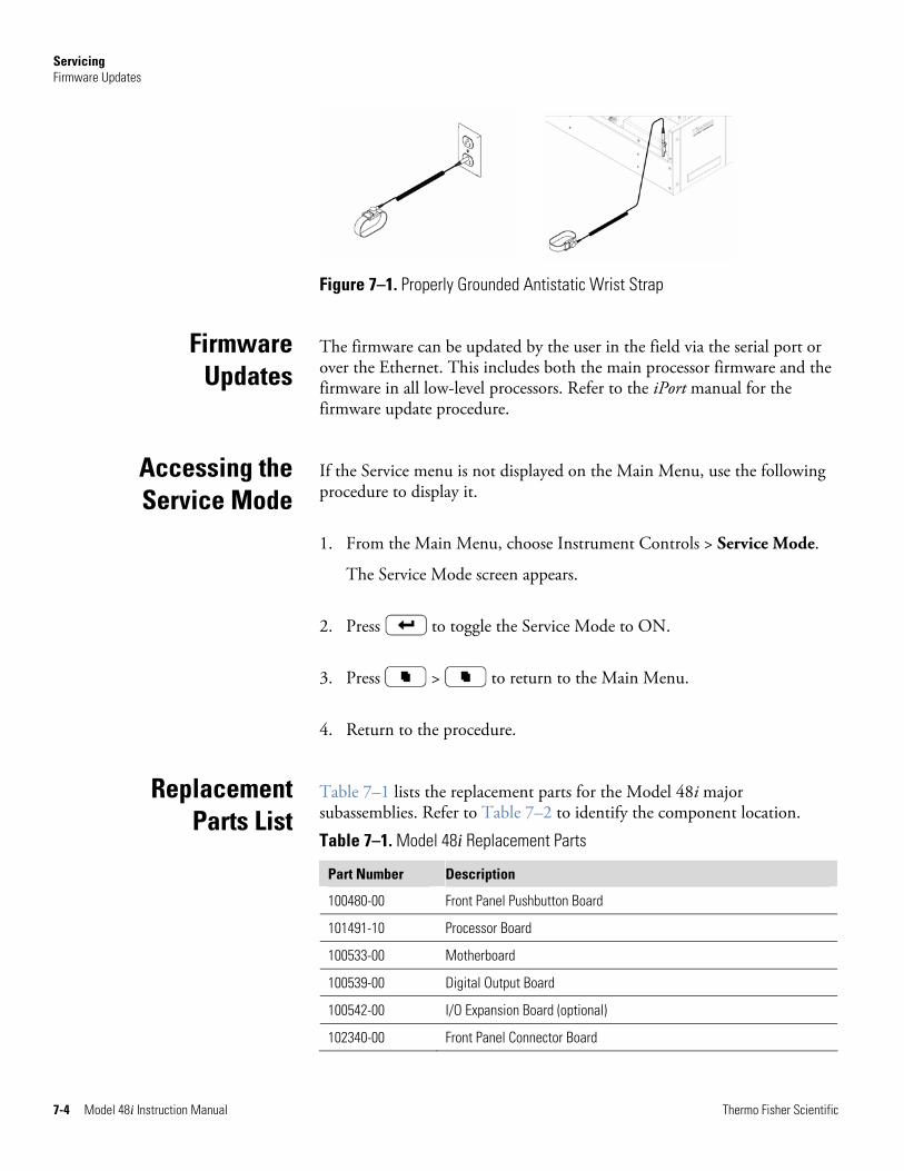
Servicing Firmware Updates
7-4 Model 48i Instruction Manual Thermo Fisher Scientific
Figure 7–1. Properly Grounded Antistatic Wrist Strap
The firmware can be updated by the user in the field via the serial port or over the Ethernet. This includes both the main processor firmware and the firmware in all low-level processors. Refer to the iPort manual for the firmware update procedure.
If the Service menu is not displayed on the Main Menu, use the following procedure to display it.
1. From the Main Menu, choose Instrument Controls > Service Mode.
The Service Mode screen appears.
2. Press to toggle the Service Mode to ON.
3. Press > to return to the Main Menu.
4. Return to the procedure.
Table 7–1 lists the replacement parts for the Model 48i major subassemblies. Refer to Table 7–2 to identify the component location.
Table 7–1. Model 48i Replacement Parts
Part Number Description
100480-00 Front Panel Pushbutton Board
101491-10 Processor Board
100533-00 Motherboard
100539-00 Digital Output Board
100542-00 I/O Expansion Board (optional)
102340-00 Front Panel Connector Board
Firmware Updates
Accessing the Service Mode
Replacement Parts List
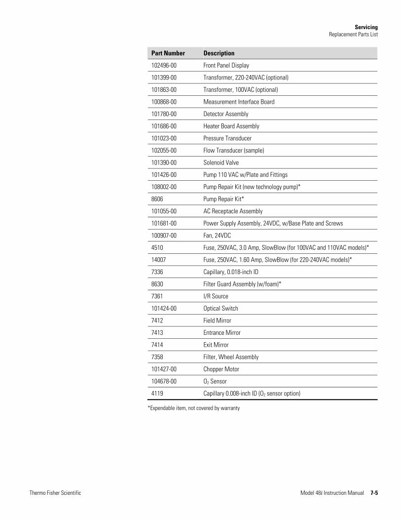
Servicing Replacement Parts List
Thermo Fisher Scientific Model 48i Instruction Manual 7-5
Part Number Description
102496-00 Front Panel Display
101399-00 Transformer, 220-240VAC (optional)
101863-00 Transformer, 100VAC (optional)
100868-00 Measurement Interface Board
101780-00 Detector Assembly
101686-00 Heater Board Assembly
101023-00 Pressure Transducer
102055-00 Flow Transducer (sample)
101390-00 Solenoid Valve
101426-00 Pump 110 VAC w/Plate and Fittings
108002-00 Pump Repair Kit (new technology pump)*
8606 Pump Repair Kit*
101055-00 AC Receptacle Assembly
101681-00 Power Supply Assembly, 24VDC, w/Base Plate and Screws
100907-00 Fan, 24VDC
4510 Fuse, 250VAC, 3.0 Amp, SlowBlow (for 100VAC and 110VAC models)*
14007 Fuse, 250VAC, 1.60 Amp, SlowBlow (for 220-240VAC models)*
7336 Capillary, 0.018-inch ID
8630 Filter Guard Assembly (w/foam)*
7361 I/R Source
101424-00 Optical Switch
7412 Field Mirror
7413 Entrance Mirror
7414 Exit Mirror
7358 Filter, Wheel Assembly
101427-00 Chopper Motor
104678-00 O2 Sensor
4119 Capillary 0.008-inch ID (O2 sensor option)
*Expendable item, not covered by warranty
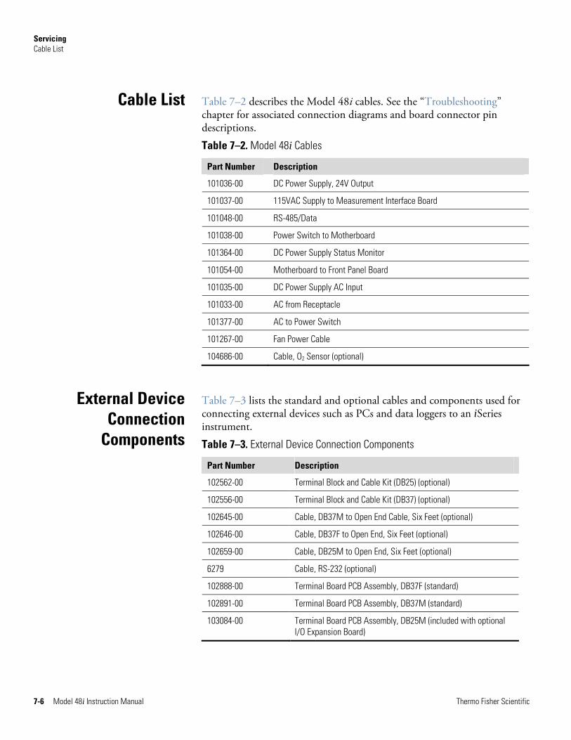
Servicing Cable List
7-6 Model 48i Instruction Manual Thermo Fisher Scientific
Table 7–2 describes the Model 48i cables. See the “Troubleshooting” chapter for associated connection diagrams and board connector pin descriptions.
Table 7–2. Model 48i Cables
Part Number Description
101036-00 DC Power Supply, 24V Output
101037-00 115VAC Supply to Measurement Interface Board
101048-00 RS-485/Data
101038-00 Power Switch to Motherboard
101364-00 DC Power Supply Status Monitor
101054-00 Motherboard to Front Panel Board
101035-00 DC Power Supply AC Input
101033-00 AC from Receptacle
101377-00 AC to Power Switch
101267-00 Fan Power Cable
104686-00 Cable, O2 Sensor (optional)
Table 7–3 lists the standard and optional cables and components used for connecting external devices such as PCs and data loggers to an iSeries instrument.
Table 7–3. External Device Connection Components
Part Number Description
102562-00 Terminal Block and Cable Kit (DB25) (optional)
102556-00 Terminal Block and Cable Kit (DB37) (optional)
102645-00 Cable, DB37M to Open End Cable, Six Feet (optional)
102646-00 Cable, DB37F to Open End, Six Feet (optional)
102659-00 Cable, DB25M to Open End, Six Feet (optional)
6279 Cable, RS-232 (optional)
102888-00 Terminal Board PCB Assembly, DB37F (standard)
102891-00 Terminal Board PCB Assembly, DB37M (standard)
103084-00 Terminal Board PCB Assembly, DB25M (included with optional I/O Expansion Board)
Cable List
External Device Connection
Components
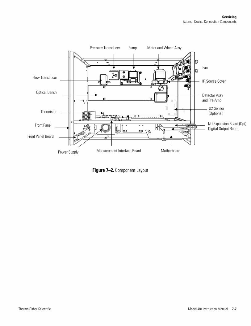
Servicing External Device Connection Components
Thermo Fisher Scientific Model 48i Instruction Manual 7-7
Front Panel Board
Optical Bench
Thermistor
Front Panel
Flow Transducer
Pump
Motherboard
Pressure Transducer
Measurement Interface Board
Motor and Wheel Assy
Fan
Detector Assy and Pre-Amp
I/O Expansion Board (Opt)Digital Output Board
IR Source Cover
Power Supply
O2 Sensor (Optional)
Figure 7–2. Component Layout
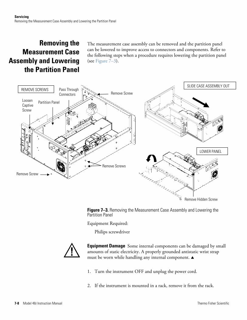
Servicing Removing the Measurement Case Assembly and Lowering the Partition Panel
7-8 Model 48i Instruction Manual Thermo Fisher Scientific
Remove Hidden Screw
Loosen Captive Screw
Partition Panel
Pass Through Connectors Remove Screw
Remove Screw
Remove Screws
The measurement case assembly can be removed and the partition panel can be lowered to improve access to connectors and components. Refer to the following steps when a procedure requires lowering the partition panel (see Figure 7–3).
Figure 7–3. Removing the Measurement Case Assembly and Lowering the Partition Panel
Equipment Required:
Philips screwdriver
Equipment Damage Some internal components can be damaged by small amounts of static electricity. A properly grounded antistatic wrist strap must be worn while handling any internal component. ▲
1. Turn the instrument OFF and unplug the power cord.
2. If the instrument is mounted in a rack, remove it from the rack.
Removing the Measurement Case
Assembly and Lowering the Partition Panel
REMOVE SCREWS SLIDE CASE ASSEMBLY OUT
LOWER PANEL
Servicing Fuse Replacement
Thermo Fisher Scientific Model 48i Instruction Manual 7-9
3. Remove the cover.
4. Disconnect the three connectors that pass through the center of the partition panel that connect to the measurement interface board.
5. Remove two screws from the left side rear of the case (viewed from front).
6. Remove one screw from the bottom rear of the case.
7. Remove one screw from the top front of the partition panel.
8. While holding the case securely, loosen the captive screw at the rear of the measurement case assembly, and pull the measurement case assembly from the rear of the case.
9. Remove the screw at the top rear of the partition panel that secures the top of the panel to the measurement case assembly, and lower the panel, being careful not to put excessive tension on the cables.
10. Re-install the measurement case assembly by following the previous steps in reverse.
Use the following procedure to replace the fuses.
Equipment Required:
Replacement fuses:
250VAC, 3 Amp, SlowBlow (for 100VAC and 110VAC models)
250VAC, 1.60 Amp, SlowBlow (for 220-240VAC models)
1. Turn the instrument OFF and unplug the power cord.
2. Remove fuse drawer, located on the AC power connector.
3. If either fuse is blown, replace both fuses.
4. Insert fuse drawer and reconnect power cord.
Fuse Replacement
Servicing Fan/Filter Replacement
7-10 Model 48i Instruction Manual Thermo Fisher Scientific
Use the following procedure to replace the fan and the fan filter (Figure 7–4).
Equipment Required:
Fan
Fan filter
Philips screwdriver
Adjustable wrench
Equipment Damage Some internal components can be damaged by small amounts of static electricity. A properly grounded antistatic wrist strap must be worn while handling any internal component. ▲
1. Turn the instrument OFF, unplug the power cord, and remove the cover.
2. Remove the fan guard and filter from the rear of the instrument by unsnapping it.
3. If the fan is not being replaced, install the new filter, snap it into place, and skip the remaining steps.
4. If possible, disconnect the fan power cable from the fan, otherwise disconnect the cable from the measurement interface board.
5. Remove the four fan mounting screws along with nuts and washers and remove the fan.
6. Install a new fan following the previous steps in reverse order.
Fan/Filter Replacement
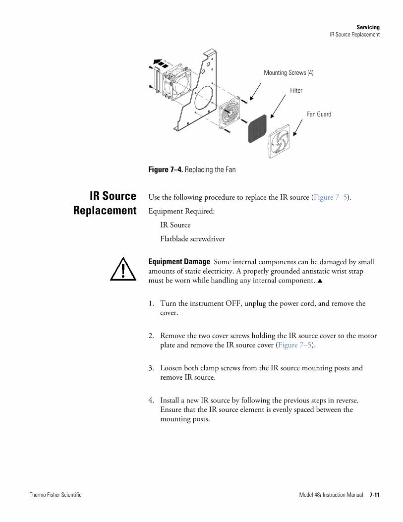
Servicing IR Source Replacement
Thermo Fisher Scientific Model 48i Instruction Manual 7-11
Figure 7–4. Replacing the Fan
Use the following procedure to replace the IR source (Figure 7–5).
Equipment Required:
IR Source
Flatblade screwdriver
Equipment Damage Some internal components can be damaged by small amounts of static electricity. A properly grounded antistatic wrist strap must be worn while handling any internal component. ▲
1. Turn the instrument OFF, unplug the power cord, and remove the cover.
2. Remove the two cover screws holding the IR source cover to the motor plate and remove the IR source cover (Figure 7–5).
3. Loosen both clamp screws from the IR source mounting posts and remove IR source.
4. Install a new IR source by following the previous steps in reverse. Ensure that the IR source element is evenly spaced between the mounting posts.
IR Source Replacement
Mounting Screws (4)
Filter
Fan Guard
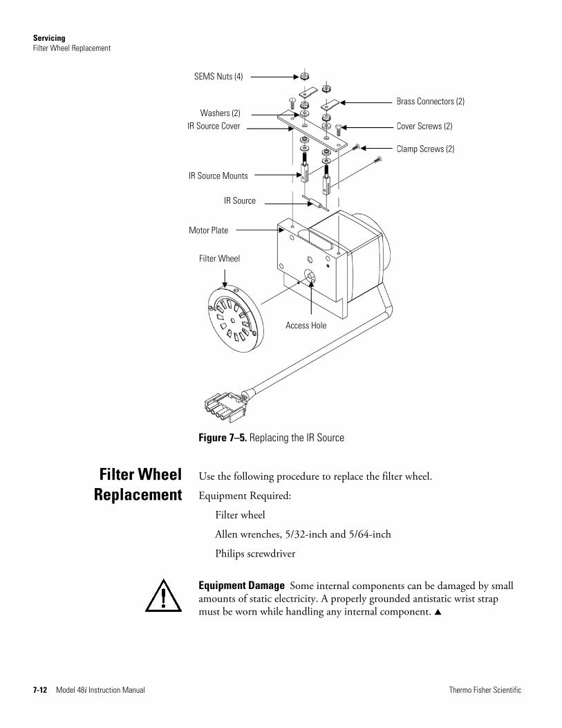
Servicing Filter Wheel Replacement
7-12 Model 48i Instruction Manual Thermo Fisher Scientific
Brass Connectors (2)
Cover Screws (2)
Clamp Screws (2)
Figure 7–5. Replacing the IR Source
Use the following procedure to replace the filter wheel.
Equipment Required:
Filter wheel
Allen wrenches, 5/32-inch and 5/64-inch
Philips screwdriver
Equipment Damage Some internal components can be damaged by small amounts of static electricity. A properly grounded antistatic wrist strap must be worn while handling any internal component. ▲
Filter Wheel Replacement
SEMS Nuts (4)
Washers (2) IR Source Cover
IR Source Mounts
IR Source
Motor Plate
Access Hole
Filter Wheel
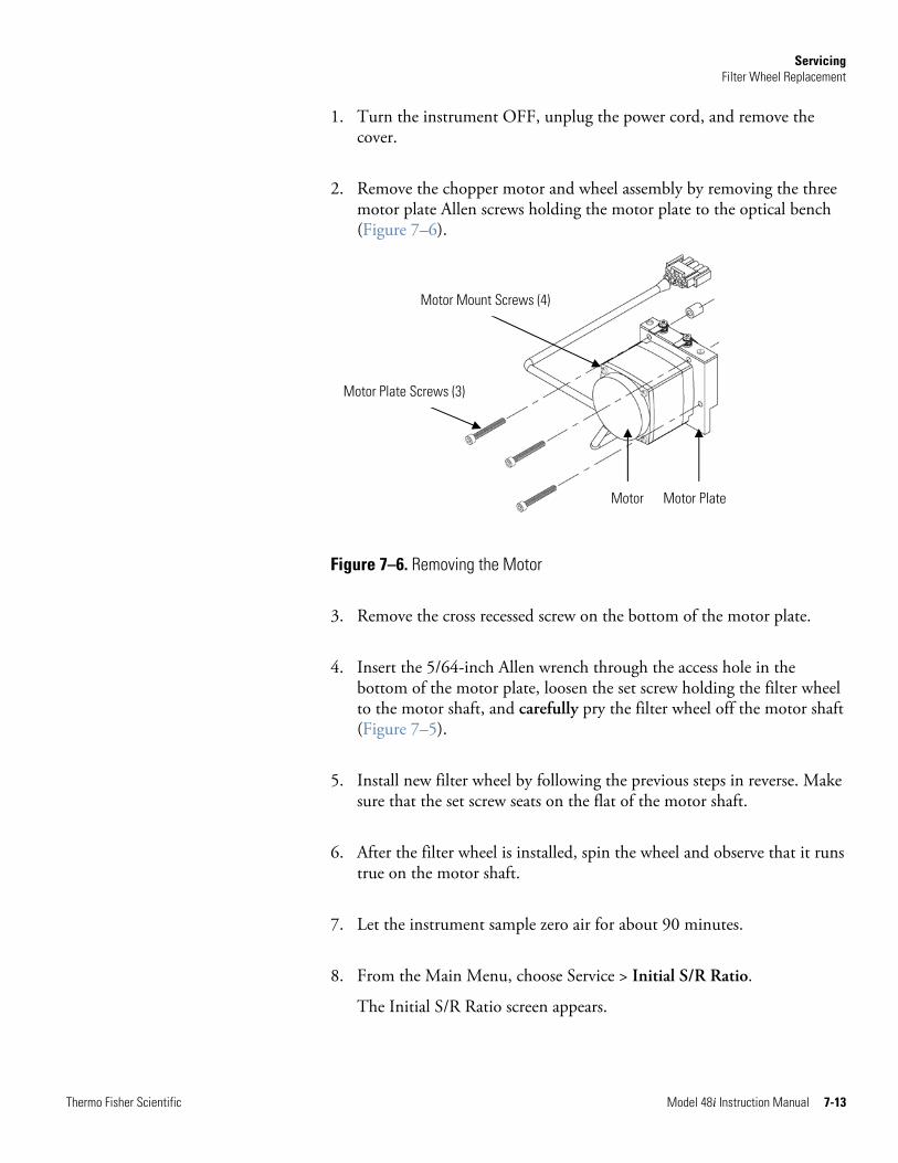
Servicing Filter Wheel Replacement
Thermo Fisher Scientific Model 48i Instruction Manual 7-13
1. Turn the instrument OFF, unplug the power cord, and remove the cover.
2. Remove the chopper motor and wheel assembly by removing the three motor plate Allen screws holding the motor plate to the optical bench (Figure 7–6).
Figure 7–6. Removing the Motor
3. Remove the cross recessed screw on the bottom of the motor plate.
4. Insert the 5/64-inch Allen wrench through the access hole in the bottom of the motor plate, loosen the set screw holding the filter wheel to the motor shaft, and carefully pry the filter wheel off the motor shaft (Figure 7–5).
5. Install new filter wheel by following the previous steps in reverse. Make sure that the set screw seats on the flat of the motor shaft.
6. After the filter wheel is installed, spin the wheel and observe that it runs true on the motor shaft.
7. Let the instrument sample zero air for about 90 minutes.
8. From the Main Menu, choose Service > Initial S/R Ratio.
The Initial S/R Ratio screen appears.
Motor Mount Screws (4)
Motor Plate Screws (3)
Motor Motor Plate
Servicing Chopper Motor Replacement
7-14 Model 48i Instruction Manual Thermo Fisher Scientific
Note If Service Mode is not displayed, refer to “Accessing the Service Mode” on page 7-4, then return to the beginning of this step. ▲
9. At the Initial S/R Ratio screen, press to select set the initial S/R ratio to the value of the current ratio and press to store the value. The initial S/R ratio should be between 1.14 and 1.18.
10. Calibrate the instrument. Refer to the “Calibration” chapter in this manual.
Use the following procedure to replace the chopper motor (Figure 7–6).
Equipment Required:
Chopper motor
Allen wrenches, 5/32-inch and 5/64-inch
Flatblade screwdriver
Equipment Damage Some internal components can be damaged by small amounts of static electricity. A properly grounded antistatic wrist strap must be worn while handling any internal component. ▲
1. Disconnect the chopper motor power cable from the MOT DRV connector on the measurement interface board.
2. Follow the directions for “Filter Wheel Replacement” procedure, up to and including Step 3.
3. Remove the chopper motor from the motor plate by removing the two screws that hold it to the motor plate.
4. Install the new chopper motor by following the previous steps in reverse.
5. Install the filter wheel on the motor shaft, make sure that the set screw seats on the flat of the motor shaft, and tighten the set screw.
6. Calibrate the instrument. Refer to the “Calibration” chapter in this manual.
Chopper Motor Replacement
Servicing Optical Bench Replacement
Thermo Fisher Scientific Model 48i Instruction Manual 7-15
Use the following procedure to replace the optical bench (Figure 7–7).
Equipment Required:
Optical bench
Philips screwdriver
Equipment Damage Some internal components can be damaged by small amounts of static electricity. A properly grounded antistatic wrist strap must be worn while handling any internal component. ▲
1. Turn the instrument OFF, unplug the power cord, and remove the cover.
2. Disconnect the chopper motor cable from the MOT DRV connector on the measurement interface board, and disconnect the detector cable from the PREAMP cable connector on the measurement interface board.
3. Disconnect the plumbing connections from the optical bench.
4. Remove the four screws holding the optical bench to the shock mounts and carefully remove the optical bench.
5. Replace the optical bench by following the previous steps in reverse.
6. Calibrate the instrument. Refer to the “Calibration” chapter in this manual.
Optical Bench Replacement
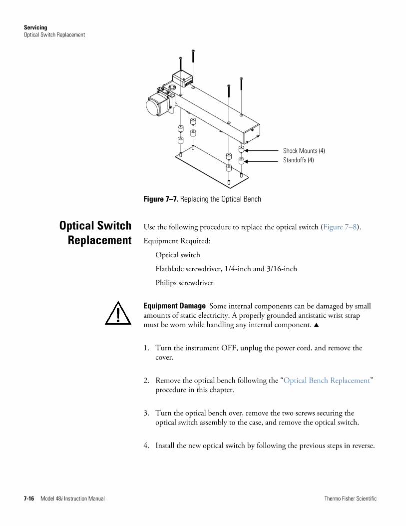
Servicing Optical Switch Replacement
7-16 Model 48i Instruction Manual Thermo Fisher Scientific
Shock Mounts (4) Standoffs (4)
Figure 7–7. Replacing the Optical Bench
Use the following procedure to replace the optical switch (Figure 7–8).
Equipment Required:
Optical switch
Flatblade screwdriver, 1/4-inch and 3/16-inch
Philips screwdriver
Equipment Damage Some internal components can be damaged by small amounts of static electricity. A properly grounded antistatic wrist strap must be worn while handling any internal component. ▲
1. Turn the instrument OFF, unplug the power cord, and remove the cover.
2. Remove the optical bench following the “Optical Bench Replacement” procedure in this chapter.
3. Turn the optical bench over, remove the two screws securing the optical switch assembly to the case, and remove the optical switch.
4. Install the new optical switch by following the previous steps in reverse.
Optical Switch Replacement
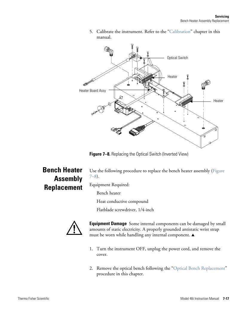
Servicing Bench Heater Assembly Replacement
Thermo Fisher Scientific Model 48i Instruction Manual 7-17
5. Calibrate the instrument. Refer to the “Calibration” chapter in this manual.
Figure 7–8. Replacing the Optical Switch (Inverted View)
Use the following procedure to replace the bench heater assembly (Figure 7–8).
Equipment Required:
Bench heater
Heat conductive compound
Flatblade screwdriver, 1/4-inch
Equipment Damage Some internal components can be damaged by small amounts of static electricity. A properly grounded antistatic wrist strap must be worn while handling any internal component. ▲
1. Turn the instrument OFF, unplug the power cord, and remove the cover.
2. Remove the optical bench following the “Optical Bench Replacement” procedure in this chapter.
Bench Heater Assembly
Replacement
Heater Board Assy
Optical Switch
Heater
Heater
Servicing Detector/Preamplifier Assembly Replacement
7-18 Model 48i Instruction Manual Thermo Fisher Scientific
3. Remove the two screws holding each heater to the bottom of the optical bench, and remove both heaters and the heater board assembly.
4. Apply heat conductive compound to the bottom of the heaters and install the new heaters and heater board assembly.
5. Calibrate the instrument. Refer to the “Calibration” chapter in this manual.
Use the following procedure to replace the detector/preamplifier assembly (Figure 7–9).
Equipment Required:
detector/preamplifier assembly
Allen wrenches, 3/32-inch and 7/64-inch
Equipment Damage Some internal components can be damaged by small amounts of static electricity. A properly grounded antistatic wrist strap must be worn while handling any internal component. ▲
1. Turn the instrument OFF, unplug the power cord, and remove the cover.
2. Disconnect the cable from the PREAMP connector on the measurement interface board and disconnect the two wires from the top of the chopper motor plate.
Detector/Preamplifier Assembly
Replacement
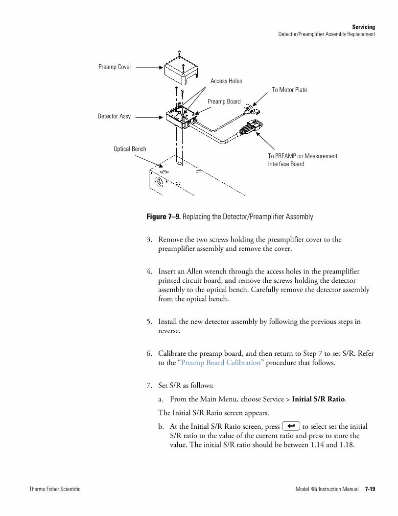
Servicing Detector/Preamplifier Assembly Replacement
Thermo Fisher Scientific Model 48i Instruction Manual 7-19
Optical Bench
Figure 7–9. Replacing the Detector/Preamplifier Assembly
3. Remove the two screws holding the preamplifier cover to the preamplifier assembly and remove the cover.
4. Insert an Allen wrench through the access holes in the preamplifier printed circuit board, and remove the screws holding the detector assembly to the optical bench. Carefully remove the detector assembly from the optical bench.
5. Install the new detector assembly by following the previous steps in reverse.
6. Calibrate the preamp board, and then return to Step 7 to set S/R. Refer to the “Preamp Board Calibration” procedure that follows.
7. Set S/R as follows:
a. From the Main Menu, choose Service > Initial S/R Ratio.
The Initial S/R Ratio screen appears.
b. At the Initial S/R Ratio screen, press to select set the initial S/R ratio to the value of the current ratio and press to store the value. The initial S/R ratio should be between 1.14 and 1.18.
Preamp Cover
Detector Assy
Access Holes
Preamp Board
To Motor Plate
To PREAMP on Measurement Interface Board
Servicing Preamp Board Calibration
7-20 Model 48i Instruction Manual Thermo Fisher Scientific
Note If Service Mode is not displayed, refer to “Accessing the Service Mode” on page 7-4, then return to the beginning of this step. ▲
8. Calibrate the instrument. Refer to the “Calibration” chapter in this manual.
Use the following procedure to calibrate the preamp board.
Equipment Damage This adjustment should only be performed by an instrument service technician. ▲
1. Let the instrument sample zero air for about 90 minutes.
2. From the Main Menu, choose Service > Preamp Board Calibration.
The Preamp Board Cal screen appears.
Note If Service Mode is not displayed, refer to “Accessing the Service Mode” on page 7-4, then return to the beginning of this step. ▲
3. At the Preamp Board Cal screen, use until either the Sample or Reference value reads more than 150,000 then press to save the value.
Use the following procedure to rebuild the pump (Figure 7–10).
Equipment Required:
Pump
Nut driver
Philips screwdriver, #2
Equipment Damage Some internal components can be damaged by small amounts of static electricity. A properly grounded antistatic wrist strap must be worn while handling any internal component. ▲
1. Turn the instrument OFF, unplug the power cord, and remove the cover.
Preamp Board Calibration
Pump Replacement
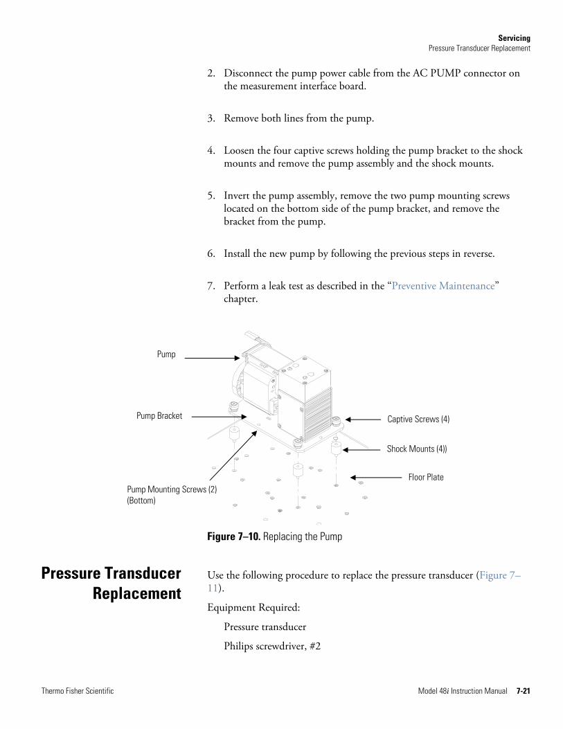
Servicing Pressure Transducer Replacement
Thermo Fisher Scientific Model 48i Instruction Manual 7-21
2. Disconnect the pump power cable from the AC PUMP connector on the measurement interface board.
3. Remove both lines from the pump.
4. Loosen the four captive screws holding the pump bracket to the shock mounts and remove the pump assembly and the shock mounts.
5. Invert the pump assembly, remove the two pump mounting screws located on the bottom side of the pump bracket, and remove the bracket from the pump.
6. Install the new pump by following the previous steps in reverse.
7. Perform a leak test as described in the “Preventive Maintenance” chapter.
Figure 7–10. Replacing the Pump
Use the following procedure to replace the pressure transducer (Figure 7–11).
Equipment Required:
Pressure transducer
Philips screwdriver, #2
Pressure Transducer Replacement
Pump
Pump Bracket
Pump Mounting Screws (2) (Bottom)
Captive Screws (4)
Shock Mounts (4))
Floor Plate
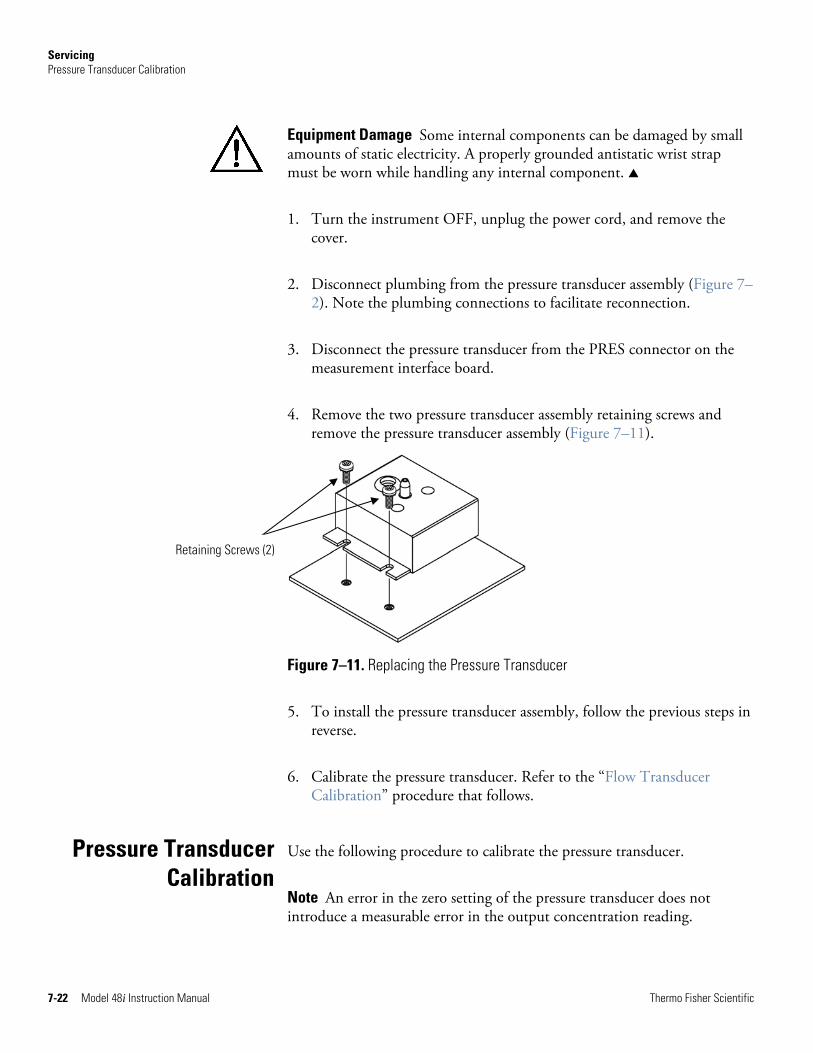
Servicing Pressure Transducer Calibration
7-22 Model 48i Instruction Manual Thermo Fisher Scientific
Equipment Damage Some internal components can be damaged by small amounts of static electricity. A properly grounded antistatic wrist strap must be worn while handling any internal component. ▲
1. Turn the instrument OFF, unplug the power cord, and remove the cover.
2. Disconnect plumbing from the pressure transducer assembly (Figure 7–2). Note the plumbing connections to facilitate reconnection.
3. Disconnect the pressure transducer from the PRES connector on the measurement interface board.
4. Remove the two pressure transducer assembly retaining screws and remove the pressure transducer assembly (Figure 7–11).
Figure 7–11. Replacing the Pressure Transducer
5. To install the pressure transducer assembly, follow the previous steps in reverse.
6. Calibrate the pressure transducer. Refer to the “Flow Transducer Calibration” procedure that follows.
Use the following procedure to calibrate the pressure transducer.
Note An error in the zero setting of the pressure transducer does not introduce a measurable error in the output concentration reading.
Pressure Transducer Calibration
Retaining Screws (2)
Servicing Pressure Transducer Calibration
Thermo Fisher Scientific Model 48i Instruction Manual 7-23
Therefore, if only a barometer is available and not a vacuum pump, only adjust the span setting. ▲
A rough check of the pressure accuracy can be made by obtaining the current barometric pressure from the local weather station or airport and comparing it to the pressure reading. However, since these pressures are usually corrected to sea level, it may be necessary to correct the reading to local pressure by subtracting 0.027 mmHg per foot of altitude. ▲
Do not attempt to calibrate the pressure transducer unless the pressure is known accurately. ▲
Equipment Required:
Vacuum pump
WARNING The service procedures in this manual are restricted to qualified service representatives. ▲
If the equipment is operated in a manner not specified by the manufacturer, the protection provided by the equipment may be impaired. ▲
Equipment Damage Some internal components can be damaged by small amounts of static electricity. A properly grounded antistatic wrist strap must be worn while handling any internal component. ▲
1. Remove the instrument cover.
2. Disconnect the tubing from the pressure transducer and connect a vacuum pump known to produce a vacuum less than 1 mmHg.
3. From the Main Menu, choose Service > Pressure Calibration.
The Pressure Sensor Cal screen appears.
Note If Service Mode is not displayed, refer to “Accessing the Service Mode” on page 7-4, then return to the beginning of this step. ▲
4. At the Pressure Sensor Cal screen, press to select Zero.
The Calibrate Pressure Zero screen appears.
Servicing Flow Transducer Replacement
7-24 Model 48i Instruction Manual Thermo Fisher Scientific
5. Wait at least 10 seconds for the zero reading to stabilize, and then press to save the zero pressure value.
6. Disconnect the pump from the pressure transducer.
7. Press to return to the Pressure Sensor Cal screen.
8. At the Pressure Sensor Cal screen, press to select Span.
The Calibrate Pressure Span screen appears.
9. Wait at least 10 seconds for the ambient reading to stabilize, use and to enter the known barometric pressure,
and press to save the pressure value.
10. Reconnect the instrument tubing to the pressure transducer.
11. Install the cover.
Use the following procedure to replace the flow transducer (Figure 7–12).
Equipment Required:
Flow transducer
Philips screwdriver, #2
Equipment Damage Some internal components can be damaged by small amounts of static electricity. A properly grounded antistatic wrist strap must be worn while handling any internal component. ▲
1. Turn the instrument OFF, unplug the power cord, and remove the cover.
2. Disconnect flow transducer cable from the FLOW connector on the measurement interface board (Figure 7–2).
3. Disconnect the plumbing connections from the flow transducer. Note the plumbing connections to facilitate reconnection.
Flow Transducer Replacement
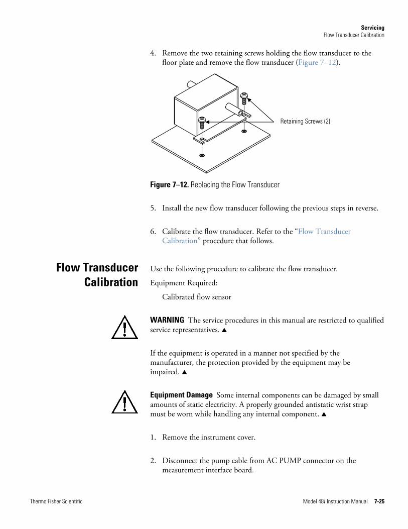
Servicing Flow Transducer Calibration
Thermo Fisher Scientific Model 48i Instruction Manual 7-25
4. Remove the two retaining screws holding the flow transducer to the floor plate and remove the flow transducer (Figure 7–12).
Figure 7–12. Replacing the Flow Transducer
5. Install the new flow transducer following the previous steps in reverse.
6. Calibrate the flow transducer. Refer to the “Flow Transducer Calibration” procedure that follows.
Use the following procedure to calibrate the flow transducer.
Equipment Required:
Calibrated flow sensor
WARNING The service procedures in this manual are restricted to qualified service representatives. ▲
If the equipment is operated in a manner not specified by the manufacturer, the protection provided by the equipment may be impaired. ▲
Equipment Damage Some internal components can be damaged by small amounts of static electricity. A properly grounded antistatic wrist strap must be worn while handling any internal component. ▲
1. Remove the instrument cover.
2. Disconnect the pump cable from AC PUMP connector on the measurement interface board.
Flow Transducer Calibration
Retaining Screws (2)
Servicing Capillary Cleaning or Replacement
7-26 Model 48i Instruction Manual Thermo Fisher Scientific
3. From the Main Menu, choose Service > Flow Calibration.
The Flow Sensor Cal screen appears.
Note If Service Mode is not displayed, refer to “Accessing the Service Mode” on page 7-4, then return to the beginning of this step. ▲
4. At the Flow Sensor Cal screen, press to select Zero.
The Calibrate Flow Zero screen appears.
5. Wait at least 10 seconds for the zero reading to stabilize, and then press to save the zero flow value.
6. Reconnect the pump cable to the AC PUMP connector on the measurement interface board.
7. Connect a calibrated flow sensor at the SAMPLE bulkhead on the rear panel.
8. Press to return to the Flow Sensor Cal screen.
9. At the Flow Sensor Cal screen, press to select Span.
The Calibrate Flow Span screen appears.
10. Wait at least 10 seconds for the reading to stabilize, use and to enter the flow sensor reading, and press to save the value.
11. Install the cover.
Use the following procedure to clean or replace the capillary (Figure 7–13).
Equipment Required:
Wrench, 5/8-inch
Capillary
Capillary cleaning wire (smaller than 0.015-inch)
Capillary Cleaning or Replacement
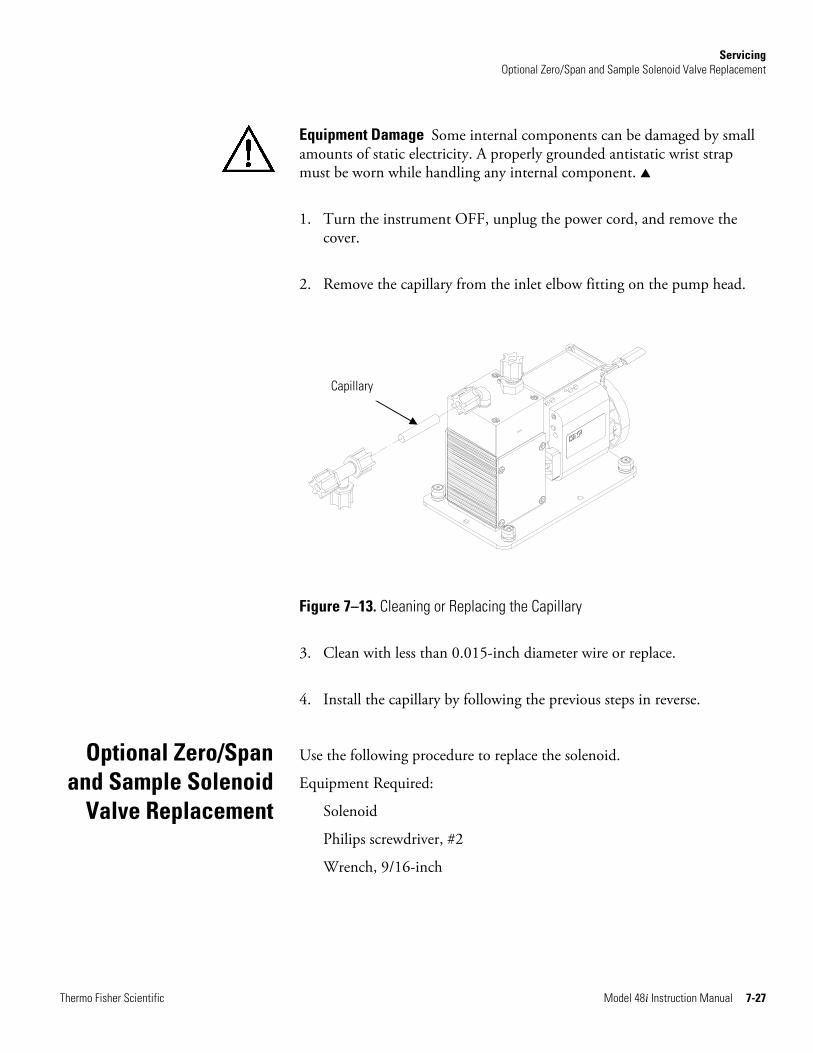
Servicing Optional Zero/Span and Sample Solenoid Valve Replacement
Thermo Fisher Scientific Model 48i Instruction Manual 7-27
Equipment Damage Some internal components can be damaged by small amounts of static electricity. A properly grounded antistatic wrist strap must be worn while handling any internal component. ▲
1. Turn the instrument OFF, unplug the power cord, and remove the cover.
2. Remove the capillary from the inlet elbow fitting on the pump head.
Figure 7–13. Cleaning or Replacing the Capillary
3. Clean with less than 0.015-inch diameter wire or replace.
4. Install the capillary by following the previous steps in reverse.
Use the following procedure to replace the solenoid.
Equipment Required:
Solenoid
Philips screwdriver, #2
Wrench, 9/16-inch
Optional Zero/Span and Sample Solenoid
Valve Replacement
Capillary
Servicing Analog Output Testing
7-28 Model 48i Instruction Manual Thermo Fisher Scientific
Equipment Damage Some internal components can be damaged by small amounts of static electricity. A properly grounded antistatic wrist strap must be worn while handling any internal component. ▲
1. Turn the instrument OFF, unplug the power cord, and remove the cover.
2. Unplug the solenoid electrical connector from the measurement interface board.
3. Remove the Teflon® lines from the solenoid.
4. Remove both screws holding the solenoid to the rear panel, and remove the solenoid.
5. Install the solenoid by following the previous steps in reverse.
6. Perform a leak test as described in the “Preventive Maintenance” chapter.
The analog outputs should be tested if the concentration value on the front panel display disagrees with the analog outputs. To check the analog outputs, connect a meter to an analog output channel (voltage or current) and compare the meter reading with the output value set on the Test Analog Outputs screen.
Equipment Required:
Multimeter
Use the following procedure to test the analog outputs.
1. Connect a meter to the channel to be tested. Figure 7–14 shows the analog output pins and Table 7–4 identifies the associated channels.
2. From the Main Menu, choose Diagnostics > Test Analog Outputs.
The Test Analog Outputs screen appears.
3. Press to scroll to the desired channel corresponding to the rear panel terminal pins where the meter is connected, and press .
Analog Output Testing
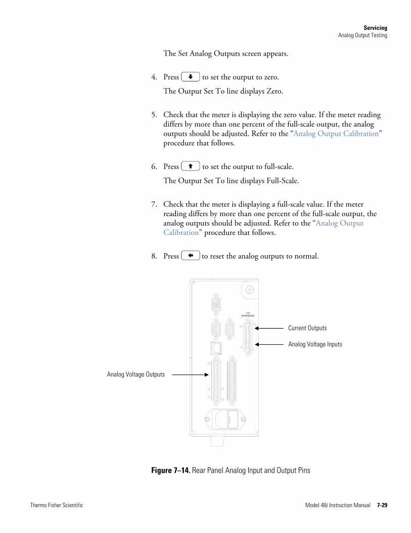
Servicing Analog Output Testing
Thermo Fisher Scientific Model 48i Instruction Manual 7-29
The Set Analog Outputs screen appears.
4. Press to set the output to zero.
The Output Set To line displays Zero.
5. Check that the meter is displaying the zero value. If the meter reading differs by more than one percent of the full-scale output, the analog outputs should be adjusted. Refer to the “Analog Output Calibration” procedure that follows.
6. Press to set the output to full-scale.
The Output Set To line displays Full-Scale.
7. Check that the meter is displaying a full-scale value. If the meter reading differs by more than one percent of the full-scale output, the analog outputs should be adjusted. Refer to the “Analog Output Calibration” procedure that follows.
8. Press to reset the analog outputs to normal.
Figure 7–14. Rear Panel Analog Input and Output Pins
Current Outputs
Analog Voltage Inputs
Analog Voltage Outputs
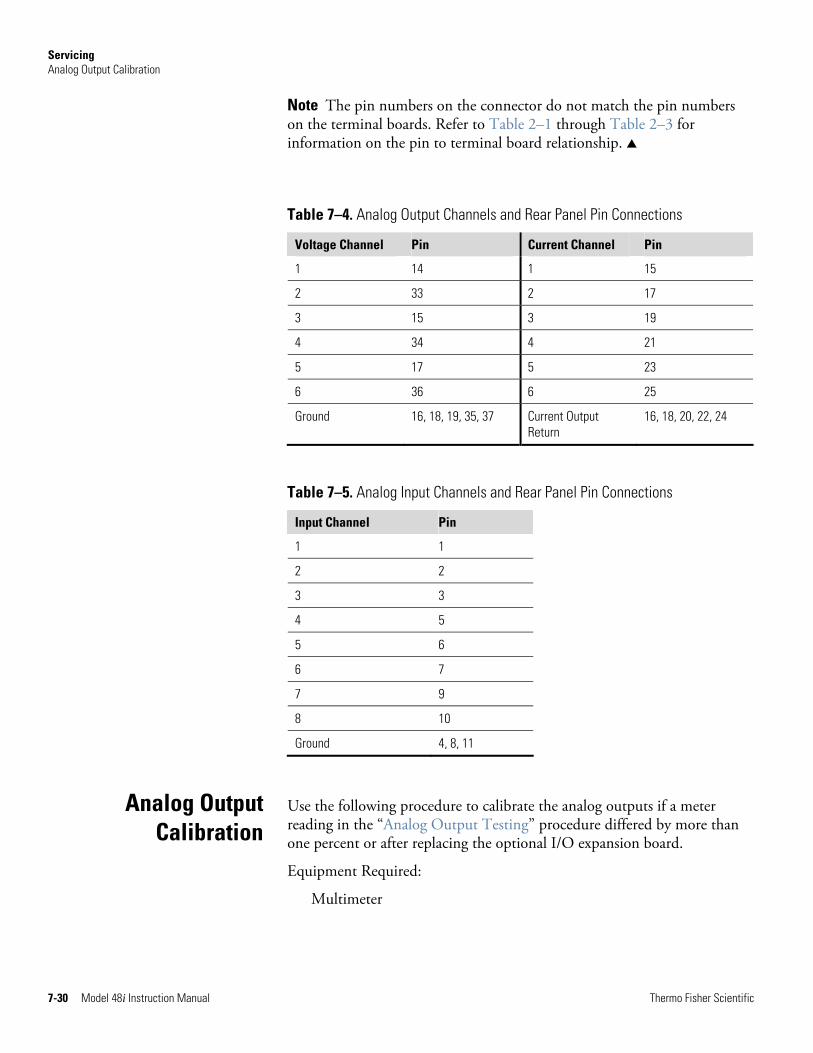
Servicing Analog Output Calibration
7-30 Model 48i Instruction Manual Thermo Fisher Scientific
Note The pin numbers on the connector do not match the pin numbers on the terminal boards. Refer to Table 2–1 through Table 2–3 for information on the pin to terminal board relationship. ▲
Table 7–4. Analog Output Channels and Rear Panel Pin Connections
Voltage Channel Pin Current Channel Pin
1 14 1 15
2 33 2 17
3 15 3 19
4 34 4 21
5 17 5 23
6 36 6 25
Ground 16, 18, 19, 35, 37 Current Output Return
16, 18, 20, 22, 24
Table 7–5. Analog Input Channels and Rear Panel Pin Connections
Input Channel Pin
1 1
2 2
3 3
4 5
5 6
6 7
7 9
8 10
Ground 4, 8, 11
Use the following procedure to calibrate the analog outputs if a meter reading in the “Analog Output Testing” procedure differed by more than one percent or after replacing the optional I/O expansion board.
Equipment Required:
Multimeter
Analog Output Calibration
Servicing Analog Input Calibration
Thermo Fisher Scientific Model 48i Instruction Manual 7-31
1. Connect a meter to the channel to be adjusted and set to voltage or current as appropriate. Figure 7–14 shows the analog output pins and Table 7–4 identifies the associated channels.
2. From the Main Menu, choose Service > Analog Out Cal.
The Analog Output Cal screen appears.
Note If Service Mode is not displayed, refer to “Accessing the Service Mode” on page 7-4, then return to the beginning of this step. ▲
3. At the Analog Output Cal menu, press to scroll to the desired voltage channel or current channel corresponding to the rear panel terminal pin where the meter is connected, then press .
4. With the cursor at Calibrate Zero, press .
The Analog Output Cal line displays Zero.
Note When calibrating the analog output, always calibrate zero first and then calibrate full-scale. ▲
5. Use until the meter reads the value shown in the Set Output To line (0.0 V, or 0.0 or 4.0 mA), then press to save the value.
6. Press to return to the previous screen.
7. Press to select Calibrate Full Scale.
8. Use until the meter reads the value shown in the Set Output To line, then press to save the value.
Use the following procedures to calibrate the analog inputs after replacing the optional I/O expansion board. These procedures include selecting analog input channels, calibrating them to zero volts, and then calibrating them to full scale using a known voltage source.
Use the following procedure to calibrate the input channels to zero volts.
Analog Input Calibration
Calibrating the InputChannels to Zero Volts
Servicing Analog Input Calibration
7-32 Model 48i Instruction Manual Thermo Fisher Scientific
1. From the Main Menu, choose Service > Analog Input Calibration.
The Analog Input Cal screen displays.
Note If Service Mode is not displayed, refer to “Accessing the Service Mode” on page 7-4, then return to the beginning of this step. ▲
2. At the Analog Input Cal screen, press to scroll to a channel, and press .
3. With the cursor at Calibrate Zero, press .
The screen displays the input voltage for the selected channel.
4. Make sure that nothing is connected to the channel input pins and press to calibrate the input voltage on the selected channel to zero volts.
The screen displays 0.00 V as the voltage setting.
5. Press > to return to the Analog Input Cal screen and repeat Steps 2 through 4 to calibrate other input channels to zero as necessary.
6. Continue with the “Calibrating the Input Channels to Full-Scale” procedure that follows.
Use the following procedure to calibrate the input channels to full-scale by applying a known voltage to the channels.
Equipment Required:
DC voltage source (greater than 0 volts and less than 10 volts)
1. Connect the known DC voltage source to the input channel (1-8) to be calibrated. Figure 7–14 shows the analog input pins and Table 7–5 identifies the associated channels.
2. From the Main Menu, choose Service > Analog Input Calibration.
The Analog Input Cal screen displays input channels 1-8.
Calibrating the Input Channels to Full-Scale
Servicing Ambient Temperature Calibration
Thermo Fisher Scientific Model 48i Instruction Manual 7-33
3. At the Analog Input Cal screen, press to scroll to the channel selected in Step 1, and press .
4. Press to scroll to Calibrate Full-scale, and press .
The screen displays the current input voltage for the selected channel.
5. Use and to enter the source voltage, and press to calibrate the input voltage for the selected channel connected
to the source voltage.
6. Press > to return to the input channels display and repeat Steps 3-5 to calibrate other input channels to the source voltage as necessary.
Use the following procedure to calibrate the ambient internal temperature for the instrument.
Equipment Required:
Calibrated thermometer or 10K ohm ±1% resistor
WARNING The service procedures in this manual are restricted to qualified service representatives. ▲
If the equipment is operated in a manner not specified by the manufacturer, the protection provided by the equipment may be impaired. ▲
Equipment Damage Some internal components can be damaged by small amounts of static electricity. A properly grounded antistatic wrist strap must be worn while handling any internal component. ▲
1. Remove the instrument cover.
2. Tape the thermometer to the thermistor, which is plugged into the measurement interface board (Figure 7–3).
Note Since the thermistors are interchangeable to an accuracy of ±0.2 °C, and have a value of 10K ohms at 25 °C, an alternate procedure is to connect an accurately known 10K resistor to the thermistor input (AMB
Ambient Temperature Calibration
Servicing I/O Expansion Board (Optional) Replacement
7-34 Model 48i Instruction Manual Thermo Fisher Scientific
TEMP) on the measurement interface board, and enter the temperature reading. ▲
A 1 °C change corresponds to a ±5% change in resistance, thus this alternative procedure can be quite accurate as a check; however, it clearly is not NIST traceable. ▲
3. From the Main Menu, choose Service > Temperature Calibration.
The Calibrate Ambient Temperature screen appears.
Note If Service Mode is not displayed, refer to “Accessing the Service Mode” on page 7-4, then return to the beginning of this step. ▲
4. Wait at least 10 seconds for the ambient reading to stabilize, use and to enter the known temperature, and
press to save the temperature value.
5. Install the cover.
Use the following procedure to replace the optional I/O expansion board (Figure 7–15).
Note After replacing the optional I/O expansion board, calibrate the current outputs and the analog voltage inputs. See “Analog Output Calibration” on page 7-30 and “Analog Input Calibration” on page 7-31 in this chapter. ▲
Equipment Required:
I/O expansion board
Nut driver, 3/16-inch
Equipment Damage Some internal components can be damaged by small amounts of static electricity. A properly grounded antistatic wrist strap must be worn while handling any internal component. ▲
1. Turn the instrument OFF, unplug the power cord, and remove the cover.
I/O Expansion Board(Optional)
Replacement
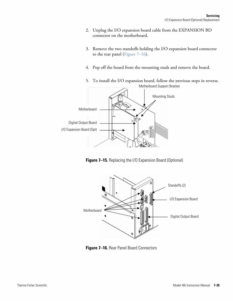
Servicing I/O Expansion Board (Optional) Replacement
Thermo Fisher Scientific Model 48i Instruction Manual 7-35
2. Unplug the I/O expansion board cable from the EXPANSION BD connector on the motherboard.
3. Remove the two standoffs holding the I/O expansion board connector to the rear panel (Figure 7–16).
4. Pop off the board from the mounting studs and remove the board.
5. To install the I/O expansion board, follow the previous steps in reverse.
Figure 7–15. Replacing the I/O Expansion Board (Optional)
Figure 7–16. Rear Panel Board Connectors
Motherboard
Digital Output Board
I/O Expansion Board (Opt)
Motherboard Support Bracket
Mounting Studs
Motherboard
Standoffs (2)
I/O Expansion Board
Digital Output Board
Servicing Internal O2 Sensor (Optional) Replacement
7-36 Model 48i Instruction Manual Thermo Fisher Scientific
Use the following procedure to replace the optional internal O2 sensor (see Figure 7–2).
Equipment Required:
O2 sensor
Philips screwdriver
Wrench, 7/16-inch
Equipment Damage Some internal components can be damaged by small amounts of static electricity. A properly grounded antistatic wrist strap must be worn while handling any internal component. ▲
1. Turn the instrument OFF, unplug the power cord, and remove the cover.
2. Disconnect the oxygen sensor ribbon cable.
3. Disconnect all plumbing connections from the oxygen sensor.
4. Loosen the four captive screws holding the converter to the floor plate and move it to the front of the case.
5. Loosen the three captive screws holding the oxygen sensor to the floor plate and remove the oxygen sensor.
6. Install new oxygen sensor by following the previous steps in reverse.
Use the following procedure to replace the digital output board (Figure 7–15).
Equipment Required:
Digital output board
Nut driver, 3/16-inch
Equipment Damage Some internal components can be damaged by small amounts of static electricity. A properly grounded antistatic wrist strap must be worn while handling any internal component. ▲
Internal O2 Sensor (Optional)
Replacement
Digital Output Board Replacement
Servicing Motherboard Replacement
Thermo Fisher Scientific Model 48i Instruction Manual 7-37
1. Turn the instrument OFF, unplug the power cord, and remove the cover.
2. Remove the I/O expansion board (optional), if used. See “I/O Expansion Board (Optional) Replacement” on page 7-34.
3. Disconnect the digital output board ribbon cable from the motherboard.
4. Using the nut driver, remove the two standoffs securing the board to the rear panel (Figure 7–16).
5. Pop off the digital output board from the mounting studs and remove the board.
6. To install the digital output board, follow the previous steps in reverse.
Use the following procedure to replace the motherboard (Figure 7–15).
Equipment Required:
Motherboard
Philips screwdriver
Nut driver, 3/16-inch
Equipment Damage Some internal components can be damaged by small amounts of static electricity. A properly grounded antistatic wrist strap must be worn while handling any internal component. ▲
1. Turn the instrument OFF, unplug the power cord, and remove the cover.
2. Remove the I/O expansion board (optional), if used. See “I/O Expansion Board (Optional) Replacement” on page 7-34.
3. Remove the digital output board. See “Digital Output Board Replacement” on page 7-36.
4. Unplug all connectors from the motherboard. Note connector locations to facilitate reconnection.
Motherboard Replacement
Servicing Measurement Interface Board Replacement
7-38 Model 48i Instruction Manual Thermo Fisher Scientific
5. Using the nut driver, remove the six standoffs securing the board to the rear panel.
6. Pop the motherboard off of the support bracket, and remove the motherboard.
7. To install the motherboard, follow the previous steps in reverse.
8. Calibrate the analog voltage outputs as defined earlier in this chapter (all ranges).
Use the following procedure to replace the measurement interface board (Figure 7–17).
Equipment Required:
Measurement interface board
Philips screwdriver, #2
Equipment Damage Some internal components can be damaged by small amounts of static electricity. A properly grounded antistatic wrist strap must be worn while handling any internal component. ▲
1. Remove the measurement bench and lower the partition panel to gain access to the measurement interface board connectors and standoffs. Refer to “Removing the Measurement Case Assembly and Lowering the Partition Panel” on page 7-8.
2. Unplug all connectors from the measurement interface board (Figure 7–17). Note the locations of the connectors to facilitate reconnection.
3. Unscrew the two screws at the top of the measurement interface board. Pop the measurement interface board off of the two bottom mounting studs and remove the board.
4. To install the measurement interface board, follow the previous steps in reverse.
5. Re-install the measurement case assembly. Refer to “Removing the Measurement Case Assembly and Lowering the Partition Panel” on page 7-8 in this chapter.
Measurement Interface Board
Replacement
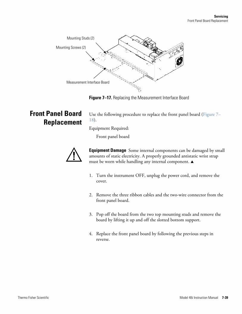
Servicing Front Panel Board Replacement
Thermo Fisher Scientific Model 48i Instruction Manual 7-39
Figure 7–17. Replacing the Measurement Interface Board
Use the following procedure to replace the front panel board (Figure 7–18).
Equipment Required:
Front panel board
Equipment Damage Some internal components can be damaged by small amounts of static electricity. A properly grounded antistatic wrist strap must be worn while handling any internal component. ▲
1. Turn the instrument OFF, unplug the power cord, and remove the cover.
2. Remove the three ribbon cables and the two-wire connector from the front panel board.
3. Pop off the board from the two top mounting studs and remove the board by lifting it up and off the slotted bottom support.
4. Replace the front panel board by following the previous steps in reverse.
Front Panel BoardReplacement
Measurement Interface Board
Mounting Studs (2)
Mounting Screws (2)
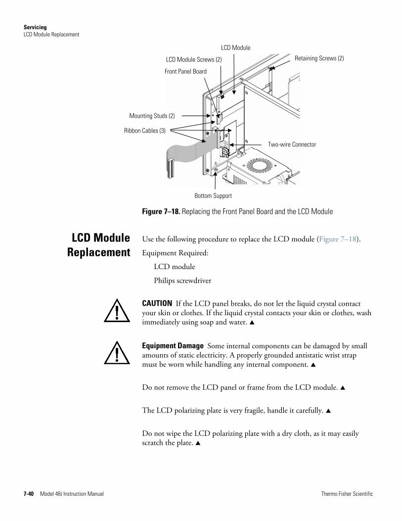
Servicing LCD Module Replacement
7-40 Model 48i Instruction Manual Thermo Fisher Scientific
Figure 7–18. Replacing the Front Panel Board and the LCD Module
Use the following procedure to replace the LCD module (Figure 7–18).
Equipment Required:
LCD module
Philips screwdriver
CAUTION If the LCD panel breaks, do not let the liquid crystal contact your skin or clothes. If the liquid crystal contacts your skin or clothes, wash immediately using soap and water. ▲
Equipment Damage Some internal components can be damaged by small amounts of static electricity. A properly grounded antistatic wrist strap must be worn while handling any internal component. ▲
Do not remove the LCD panel or frame from the LCD module. ▲
The LCD polarizing plate is very fragile, handle it carefully. ▲
Do not wipe the LCD polarizing plate with a dry cloth, as it may easily scratch the plate. ▲
LCD Module Replacement
LCD Module
LCD Module Screws (2)
Front Panel Board
Mounting Studs (2)
Ribbon Cables (3)
Bottom Support
Two-wire Connector
Retaining Screws (2)
Servicing Service Locations
Thermo Fisher Scientific Model 48i Instruction Manual 7-41
Do not use alcohol, acetone, MEK or other Ketone based or aromatic solvents to clean the LCD module, but rather use a soft cloth moistened with a naphtha cleaning solvent. ▲
Do not place the LCD module near organic solvents or corrosive gases. ▲
Do not shake or jolt the LCD module. ▲
1. Turn the instrument OFF, unplug the power cord, and remove the cover.
2. Disconnect the ribbon cable and the two-wire connector from the front panel board.
3. Remove the four screws at the corners of the LCD module.
4. Slide the LCD module out towards the center of the instrument.
5. Replace the LCD module by following the previous steps in reverse.
Note The optimal contrast will change from one LCD screen to another. After replacing the LCD screen, the contrast may need to be reset. If the content on the screen is visible, select Instrument Controls > Screen Contrast and adjust the screen contrast. If the content on the screen is not visible, use the “set contrast 10” C-Link command to set screen constrast to mid range, then optimize the contrast. See the “C-Link Protocol Commands” appendix for more information on this command. ▲
For additional assistance, service is available from exclusive distributors worldwide. Contact one of the phone numbers below for product support and technical information or visit us on the web at www.thermo.com/aqi.
1-866-282-0430 Toll Free
1-508-520-0430 International
Service Locations

Thermo Fisher Scientific Model 48i Instruction Manual 8-1
Chapter 8 System Description
This chapter describes the function and location of the system components, provides an overview of the firmware structure, and includes a description of the system electronics and input/output connections and functions as follows:
● “Hardware” on page 8-1
● “Firmware” on page 8-3
● “Electronics” on page 8-5
● “I/O Components” on page 8-8
Model 48i hardware components (Figure 8–1) include:
● Optical bench
● Band-pass filter
● Bench heater board
● Chopper motor
● Optical pickup
● Gas filter wheel
● Infrared source
● Pre-amplifier assembly with IR detector
● Sample flow sensor
● Pressure transducer
● Capillary
● Pump
● Purge flow switch (optional)
Hardware
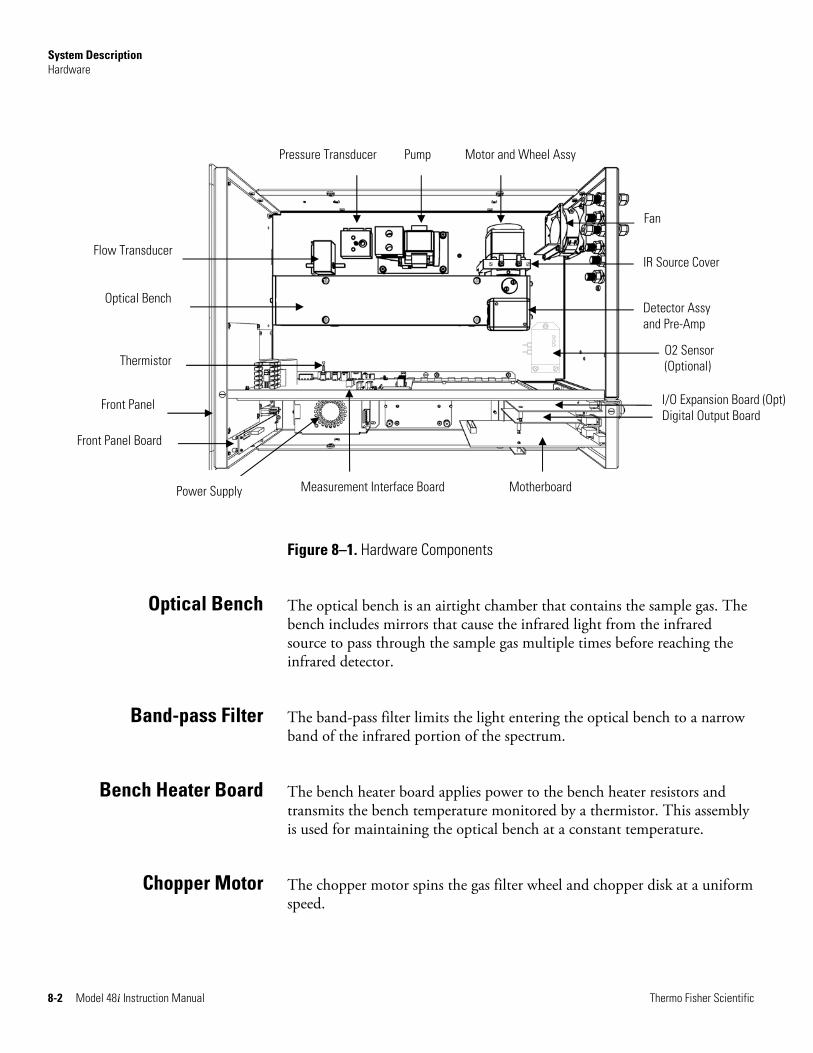
System Description Hardware
8-2 Model 48i Instruction Manual Thermo Fisher Scientific
Front Panel Board
Optical Bench
Thermistor
Front Panel
Flow Transducer
Pump
Motherboard
Pressure Transducer
Measurement Interface Board
Motor and Wheel Assy
Fan
Detector Assy and Pre-Amp
I/O Expansion Board (Opt)Digital Output Board
IR Source Cover
Power Supply
O2 Sensor (Optional)
Figure 8–1. Hardware Components
The optical bench is an airtight chamber that contains the sample gas. The bench includes mirrors that cause the infrared light from the infrared source to pass through the sample gas multiple times before reaching the infrared detector.
The band-pass filter limits the light entering the optical bench to a narrow band of the infrared portion of the spectrum.
The bench heater board applies power to the bench heater resistors and transmits the bench temperature monitored by a thermistor. This assembly is used for maintaining the optical bench at a constant temperature.
The chopper motor spins the gas filter wheel and chopper disk at a uniform speed.
Optical Bench
Band-pass Filter
Bench Heater Board
Chopper Motor
System Description Firmware
Thermo Fisher Scientific Model 48i Instruction Manual 8-3
The optical pickup detects the position of the gas filter wheel, provides synchronizing signals for the signal demodulation, and provides a method for checking the chopper motor speed.
The gas filter wheel contains samples of CO and N2 gas that filter the radiation from the infrared source. A chopper disk that rotates along with the wheel periodically interrupts the radiation to create a modulated signal.
The infrared source is a special wire-wound resistor operated at high temperature to create infrared radiation.
The pre-amplifier assembly is mounted on the optical bench along with an infrared detector that detects the energy of the infrared light passing through the optical bench. It amplifies the pulsating signal from the infrared detector.
The sample flow sensor, located at the optical bench outlet, measures the flow of sample through the optical bench.
The pressure transducer measures the pressure of the sample gas.
The capillary and the pump control the sample gas flow.
The pump draws the sample gas through the optical filter bench.
The purge flow switch monitors the flow of purge gas when the filter wheel purge gas option is installed.
The processor firmware tasks are organized into four areas:
● Instrument control
● Monitoring signals
● Measurement calculations
● Output communication
Optical Pickup
Gas Filter Wheel
Infrared Source
Pre-amplifier Assembly with IR Detector
Sample Flow Sensor
Pressure Transducer
Capillary
Pump
Purge Flow Switch (optional)
Firmware
System Description Firmware
8-4 Model 48i Instruction Manual Thermo Fisher Scientific
Low-level embedded processors are used to control the various functions on the boards, such as analog and digital I/O. These processors are controlled over a serial interface with a single high-level processor that also controls the front-panel user interface. The low-level processors all run a common piece of firmware that is bundled with the high-level firmware and loaded on power-up if a different version is detected.
Each board has a specific address that is used to identify to the firmware what functions are supported on that board. This address is also used for the communications between the low-level processors and the high-level processor.
Every tenth of a second, the frequency counters, analog I/O, and digital I/O are read and written to by the low-level processors. The counters are accumulated over the past second and the analog inputs are averaged over that second. The high-level processor polls the low-level processors once per second to exchange the measurement and control data.
Signals are gathered from the low-level processors once per second, and then processed by the high-level processor to produce the final measurement values. The one-second accumulated counts are accumulated and reported for the user-specified averaging time. If this averaging time is greater than ten seconds, the measurement is still reported every 10 seconds. The one-second average of the other analog inputs are reported directly (no additional signal conditioning is performed by the high-level processor).
The front panel display, serial and Ethernet data ports, and analog outputs are the means of communicating the results of the above calculations. The front panel display presents the concentrations simultaneously. The display is updated every 1-10 seconds, depending on the averaging time.
The analog output ranges are user selectable via the firmware. The analog outputs are defaulted based on the measurement range. The defaults are calculated by dividing the data values by the full-scale range for each of the three parameters and then multiplying each result by the user-selected output range. Negative concentrations can be represented as long as they are within -5% of full-scale. The zero and span values may be set by the user to any desired value.
Instrument Control
Monitoring Signals
Output Communication
System Description Electronics
Thermo Fisher Scientific Model 48i Instruction Manual 8-5
All electronics operate from a universal switching supply, which is capable of auto-sensing the input voltage and working over all specified operating ranges.
Internal pumps and heaters all operate on 110VAC. An optional transformer is required if operating on the 210-250VAC or 90-110VAC ranges.
An on/off switch controls all power to the instrument, and is accessible on the front panel.
The motherboard contains the main processor, power supplies, and a sub-processor, and serves as the communication hub for the instrument. The motherboard receives operator inputs from the front panel function keys and/or over I/O connections on the rear panel. The motherboard sends commands to the other boards to control the functions of the instrument and to collect measurement and diagnostic information. The motherboard outputs instrument status and measurement data to the graphics display and to the rear-panel I/O. The motherboard also contains I/O circuitry and the associated connector to monitor external digital status lines and to output analog voltages that represent the measurement data. Connectors located on the motherboard include:
External connectors:
● External Accessory
● RS-232/485 Communications (two connectors)
● Ethernet Communications
● I/O connector with Power Fail Relay, 16 Digital Inputs, and 6 Analog Voltage Outputs.
Internal connectors:
● Function Key Panel and Display
● Measurement Interface Board
● I/O Expansion Board
● Digital Output Board
● AC Distribution
Electronics
Motherboard
System Description Electronics
8-6 Model 48i Instruction Manual Thermo Fisher Scientific
The measurement interface board serves as a central connection area for all measurement electronics in the instrument. It contains power supplies and interface circuitry for sensors and control devices in the measurement system. It sends status data to the motherboard and receives control signals from the motherboard.
Connectors located on the measurement interface board include:
● Data communication with the motherboard
● 24V and 120VAC power supply inputs
● Fan and solenoid outputs
● 120VAC output and thermistor input from the bench heater board
● Flow and pressure sensor inputs
● Chopper motor output
● Optical pickup input
● Pre-amp board
● Ambient temperature thermistor
● Purge flow switch input
The flow sensor assembly consists of a board containing an instrumentation amplifier and a flow transducer with input and output gas fittings. The flow transducer output is produced by measuring the pressure difference across a precision orifice. This unit is used for measuring the flow of sample gas in the measurement system.
The pressure sensor assembly consists of a board containing an instrumentation amplifier and a pressure transducer with a gas input fitting. The pressure transducer output is produced by measuring the pressure difference between the sample gas pressure and ambient air pressure.
Measurement InterfaceBoard
Measurement Interface Board Connectors
Flow Sensor Assembly
Pressure Sensor Assembly
System Description Electronics
Thermo Fisher Scientific Model 48i Instruction Manual 8-7
The bench heater board provides connections for the optical bench heater resistors and optical bench temperature thermistor.
The optical bench temperature is measured with a thermistor. The voltage across the thermistor is applied to the main processor and used to display and control the temperature of the optical bench. The main processor compares the voltage to a set point and controls the 120VAC power to the bench heater resistors to maintain a constant bench temperature.
The pre-amp board assembly amplifies the signal from an infrared sensor that receives light passing through the sample gas. The preamplifier gain is adjusted by the main processor to bring the signal amplitude within a normal operating range. The output of the pre-amp board is fed to the measurement interface board. Wires from the pre-amp board apply power to the infrared source resistor. The pre-amp board assembly is mounted on top of the optical bench.
The digital output board connects to the motherboard and provides solenoid driver outputs and relay contact outputs to a connector located on the rear panel of the instrument. Ten relay contacts, normally open (with power off), are provided, which are electrically isolated from each other. Eight solenoid driver outputs (open collector) are provided along with a corresponding +24VDC supply pin on the connector.
The I/O expansion board connects to the motherboard and adds the capability to input external analog voltage signals and to output analog currents via a connector located on the rear panel of the instrument. It contains local power supplies, a DC/DC isolator supply, a sub-processor and analog circuits. Eight analog voltage inputs are provided with an input voltage range of 0V to10VDC. Six current outputs are provided with a normal operating range of 0 to 20 mA.
The front panel connector board interfaces between the motherboard and the function key panel and graphics display. It serves as central location to tie the three connectors required for the function key panel, the graphics display control lines, and the graphics display backlight to a single ribbon cable extending back to the motherboard. This board also includes signal buffers for the graphics display control signals and a high voltage power supply for the graphics display backlight.
Bench Heater Board
Pre-amp Board Assembly
Digital Output Board
I/O Expansion Board (Optional)
Front Panel Connector Board
System Description I/O Components
8-8 Model 48i Instruction Manual Thermo Fisher Scientific
External I/O is driven from a generic bus that is capable of controlling the following devices:
● Analog output (voltage and current)
● Analog input (voltage)
● Digital output (TTL levels)
● Digital input (TTL levels)
Note The instrument has spare solenoid valve drivers and I/O support for future expansion. ▲
The instrument provides six analog voltage outputs. Each may be firmware configured for any one of the following ranges, while maintaining a minimum resolution of 12 bits:
● 0-100mV
● 0-1V
● 0-5V
● 0-10V
The user can calibrate each analog output zero and span point through the firmware. At least 5% of full-scale over and under range are also supported, but may be overridden in the firmware, if required.
The analog outputs may be assigned to any measurement or diagnostic channel with a user-defined range in the units of the selected parameter. The voltage outputs are independent of the current outputs.
The optional I/O expansion board includes six isolated current outputs. These are firmware configured for any one of the following ranges, while maintaining a minimum resolution of 11 bits:
● 0-20 mA
● 4-20 mA
The user can calibrate each analog output zero and span point through firmware. At least 5% of full-scale over and under range are also supported, but may be overridden in the firmware, if required.
I/O Components
Analog Voltage Outputs
Analog Current Outputs (Optional)
System Description I/O Components
Thermo Fisher Scientific Model 48i Instruction Manual 8-9
The analog outputs may be assigned to any measurement or diagnostic channel with a user-defined range in the units of the selected parameter. The current outputs are independent of the voltage outputs. The current outputs are isolated from the instrument power and ground, but they share a common return line (Isolated GND).
Eight analog voltage inputs are used to gather measurement data from third-party devices. The user may assign a label, unit, and a conversion table (2 to 10 points). Each point in the conversion table consists of an analog input voltage value (0-10.5 V) and a corresponding user-defined reading value. Only two points are necessary for linear inputs, however a larger number of points may be used to approximate non-linear inputs. All voltage inputs have a resolution of 12 bits over the range of 0 to 10.5 volts.
The instrument includes one power fail relay on the motherboard and ten digital output relays on the digital output board. These are reed relays rated for at least 500 mA @ 200VDC.
The power fail relay is Form C (both normally opened and normally closed contacts). All other relays are Form A (normally opened contacts) and are used to provide alarm status and mode information from the analyzer, as well as remote control to other devices, such as for controlling valves during calibration. The user may select what information is sent out from each relay and whether the active state is opened or closed.
Sixteen digital inputs are available, which may be programmed to signal instrument modes and special conditions including:
● Zero Gas Mode
● Span Gas Mode
● Set Background
● Calibrate to low range span concentration
● Calibrate to high range span concentration
● Analog outputs to zero
● Analog outputs to full-scale
● External Alarms
The actual use of these inputs will vary based on analyzer configuration.
The digital inputs are TTL level compatible and are pulled up within the analyzer. The active state can be user defined in firmware.
Analog Voltage Inputs (Optional)
Digital Relay Outputs
Digital Inputs
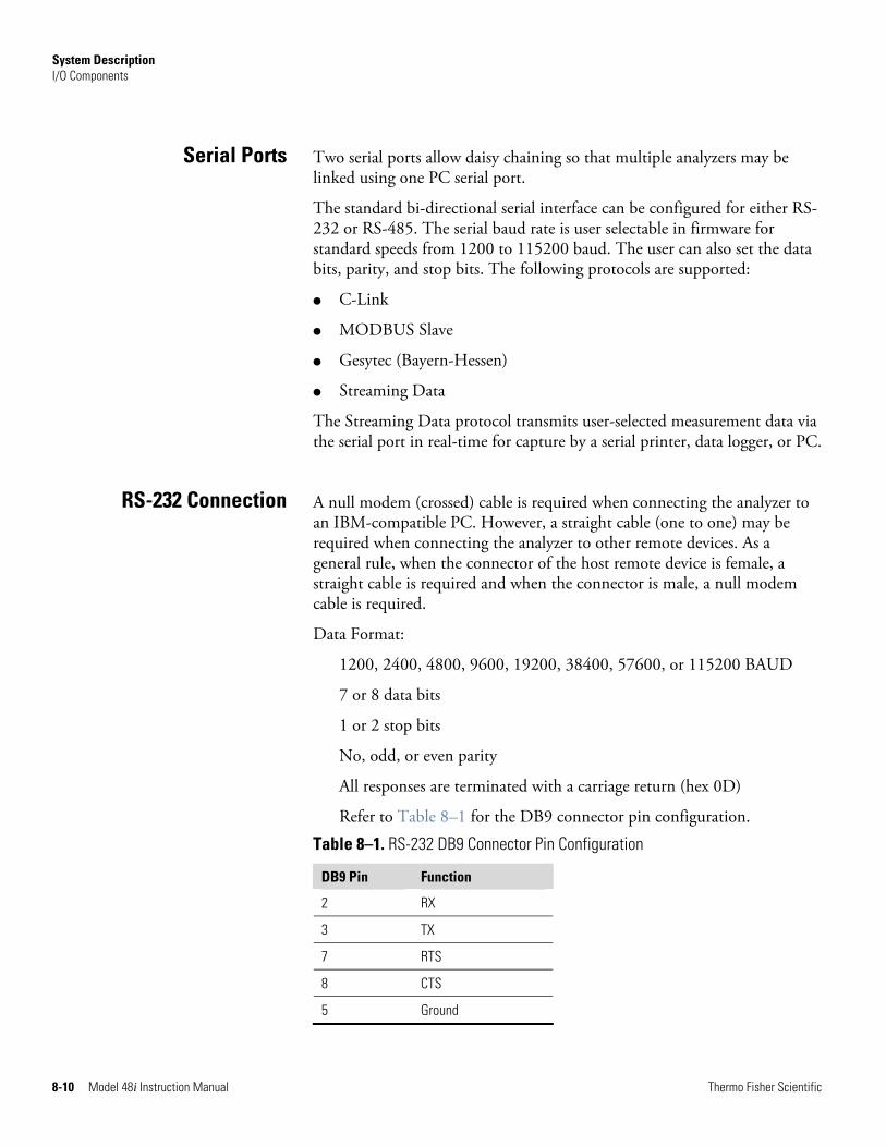
System Description I/O Components
8-10 Model 48i Instruction Manual Thermo Fisher Scientific
Two serial ports allow daisy chaining so that multiple analyzers may be linked using one PC serial port.
The standard bi-directional serial interface can be configured for either RS-232 or RS-485. The serial baud rate is user selectable in firmware for standard speeds from 1200 to 115200 baud. The user can also set the data bits, parity, and stop bits. The following protocols are supported:
● C-Link
● MODBUS Slave
● Gesytec (Bayern-Hessen)
● Streaming Data
The Streaming Data protocol transmits user-selected measurement data via the serial port in real-time for capture by a serial printer, data logger, or PC.
A null modem (crossed) cable is required when connecting the analyzer to an IBM-compatible PC. However, a straight cable (one to one) may be required when connecting the analyzer to other remote devices. As a general rule, when the connector of the host remote device is female, a straight cable is required and when the connector is male, a null modem cable is required.
Data Format:
1200, 2400, 4800, 9600, 19200, 38400, 57600, or 115200 BAUD
7 or 8 data bits
1 or 2 stop bits
No, odd, or even parity
All responses are terminated with a carriage return (hex 0D)
Refer to Table 8–1 for the DB9 connector pin configuration.
Table 8–1. RS-232 DB9 Connector Pin Configuration
DB9 Pin Function
2 RX
3 TX
7 RTS
8 CTS
5 Ground
Serial Ports
RS-232 Connection
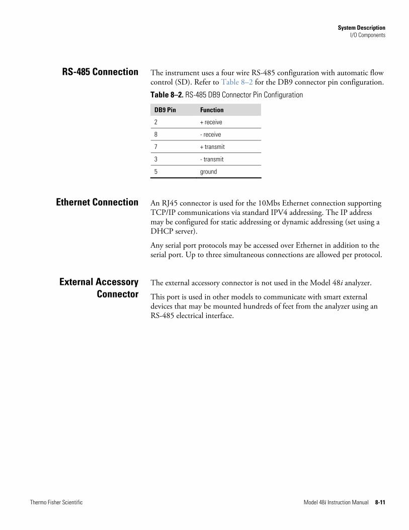
System Description I/O Components
Thermo Fisher Scientific Model 48i Instruction Manual 8-11
The instrument uses a four wire RS-485 configuration with automatic flow control (SD). Refer to Table 8–2 for the DB9 connector pin configuration.
Table 8–2. RS-485 DB9 Connector Pin Configuration
DB9 Pin Function
2 + receive
8 - receive
7 + transmit
3 - transmit
5 ground
An RJ45 connector is used for the 10Mbs Ethernet connection supporting TCP/IP communications via standard IPV4 addressing. The IP address may be configured for static addressing or dynamic addressing (set using a DHCP server).
Any serial port protocols may be accessed over Ethernet in addition to the serial port. Up to three simultaneous connections are allowed per protocol.
The external accessory connector is not used in the Model 48i analyzer.
This port is used in other models to communicate with smart external devices that may be mounted hundreds of feet from the analyzer using an RS-485 electrical interface.
RS-485 Connection
Ethernet Connection
External Accessory Connector

Thermo Fisher Scientific Model 48i Instruction Manual 9-1
Chapter 9 Optional Equipment
The Model 48i is available with the following options:
● “Internal Zero/Span Assembly” on page 9-1
● “Internal Oxygen (O2) Sensor” on page 9-1
● “Internal Zero Air Scrubber” on page 9-4
● “Filter Wheel Purge” on page 9-4
● “Teflon Particulate Filter” on page 9-5
● “I/O Expansion Board Assembly” on page 9-5
● “Terminal Block and Cable Kits” on page 9-5
● “Cables” on page 9-6
● “Mounting Options” on page 9-7
With the internal zero/span assembly option, a source of span gas is connected to the SPAN port and a source of zero air is connected to the ZERO port. Zero and span gas should be supplied at atmospheric pressure. It may be necessary to use an atmospheric dump bypass plumbing arrangement to accomplish this.
For more information, refer to the “Installation” chapter and the “Operation” chapter.
The Internal Oxygen (O2) Sensor option provides a paramagnetic sensor for O2 concentration measurement and CO correction. This option allows the user to correct the CO readings for the amount of oxygen in the sample. Selectable O2 concentrations can be used as the correction factor.
Figure 9–1 shows how this option is integrated with the Model 48i with and without the zero/span option.
Internal Zero/Span Assembly
Internal Oxygen (O2) Sensor
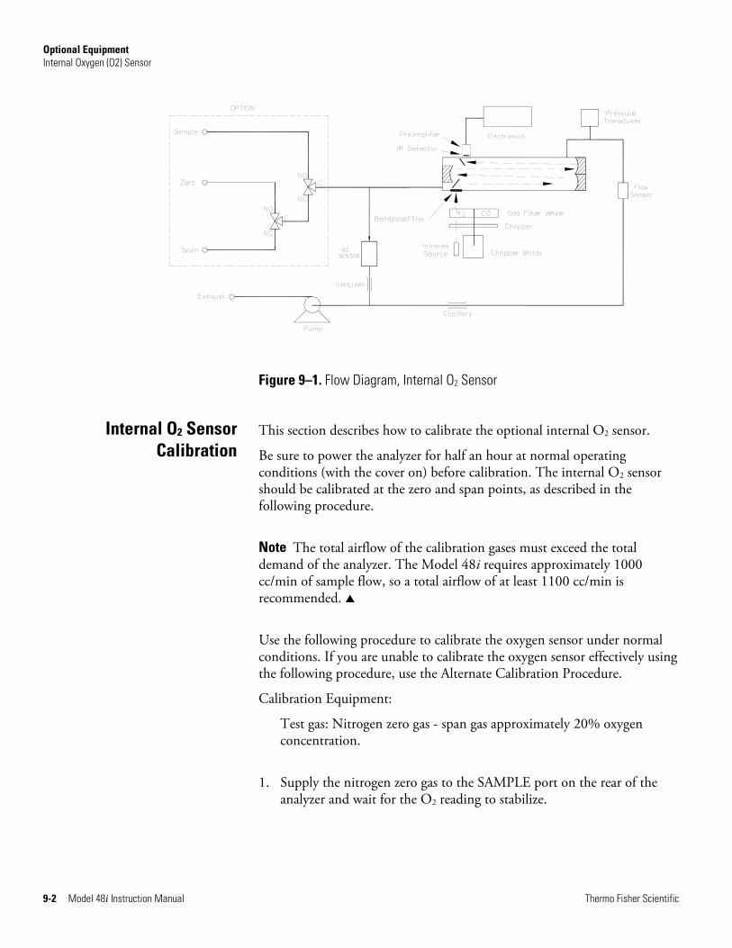
Optional Equipment Internal Oxygen (O2) Sensor
9-2 Model 48i Instruction Manual Thermo Fisher Scientific
Figure 9–1. Flow Diagram, Internal O2 Sensor
This section describes how to calibrate the optional internal O2 sensor.
Be sure to power the analyzer for half an hour at normal operating conditions (with the cover on) before calibration. The internal O2 sensor should be calibrated at the zero and span points, as described in the following procedure.
Note The total airflow of the calibration gases must exceed the total demand of the analyzer. The Model 48i requires approximately 1000 cc/min of sample flow, so a total airflow of at least 1100 cc/min is recommended. ▲
Use the following procedure to calibrate the oxygen sensor under normal conditions. If you are unable to calibrate the oxygen sensor effectively using the following procedure, use the Alternate Calibration Procedure.
Calibration Equipment:
Test gas: Nitrogen zero gas - span gas approximately 20% oxygen concentration.
1. Supply the nitrogen zero gas to the SAMPLE port on the rear of the analyzer and wait for the O2 reading to stabilize.
Internal O2 Sensor Calibration
Optional Equipment Internal Oxygen (O2) Sensor
Thermo Fisher Scientific Model 48i Instruction Manual 9-3
2. From the Main Menu choose Calibration > Calibrate O2 Background and press to set the O2 background to zero.
3. Supply the O2 Span gas to the SAMPLE port on the rear of the analyzer and wait for the O2 reading to stabilize.
4. From the Main Menu choose Calibration > Calibrate O2 Coefficient, enter the span concentration, and press to set the O2 coefficient.
Note If you were unable to calibrate the oxygen sensor effectively using this procedure, recalibrate using the “Alternate Sensor Calibration” procedure that follows. ▲
Use the following procedure if the standard calibration procedure described previously fails to calibrate properly or for high altitude (5000m/15400 ft) calibration.
1. Supply the nitrogen zero gas to the SAMPLE port on the rear of the analyzer.
2. From the Main Menu choose Calibration Factors > O2 Background, set the O2 background to zero, and press to set the O2 background.
3. Use the screwdriver to adjust zero potentiometer RV1 such that the O2 value reads 0.00% O2.
4. Use the screwdriver to adjust the span potentiometer RV2 fully clockwise.
5. Supply the O2 span gas to the SAMPLE port on the rear of the analyzer.
6. From the Main Menu choose Calibration Factors > O2 Coefficient, set the O2 coefficient to 1.000, and press to set the O2 coefficient.
7. Use the screwdriver to adjust the coarse span potentiometer RV3 such that the O2 reading is 20% greater than the calibration gas value. For example, 25% O2 span gas should be set to produce an output of 30.00% O2.
Alternate Sensor Calibration
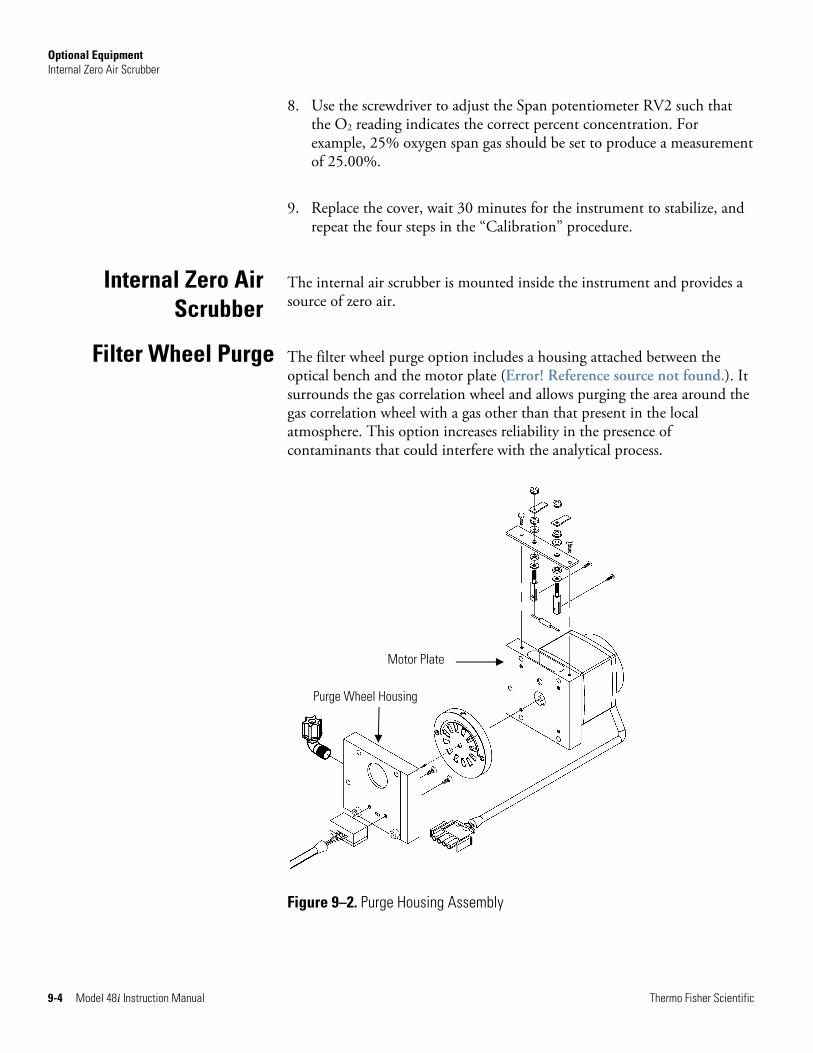
Optional Equipment Internal Zero Air Scrubber
9-4 Model 48i Instruction Manual Thermo Fisher Scientific
8. Use the screwdriver to adjust the Span potentiometer RV2 such that the O2 reading indicates the correct percent concentration. For example, 25% oxygen span gas should be set to produce a measurement of 25.00%.
9. Replace the cover, wait 30 minutes for the instrument to stabilize, and repeat the four steps in the “Calibration” procedure.
The internal air scrubber is mounted inside the instrument and provides a source of zero air.
The filter wheel purge option includes a housing attached between the optical bench and the motor plate (Error! Reference source not found.). It surrounds the gas correlation wheel and allows purging the area around the gas correlation wheel with a gas other than that present in the local atmosphere. This option increases reliability in the presence of contaminants that could interfere with the analytical process.
Figure 9–2. Purge Housing Assembly
Internal Zero Air Scrubber
Filter Wheel Purge
Purge Wheel Housing
Motor Plate
Optional Equipment Teflon Particulate Filter
Thermo Fisher Scientific Model 48i Instruction Manual 9-5
The stability of the purge gas is very important. Since this gas is in the same optical path as the sample, changes in the composition of the purge gas can change the calibration of the instrument. Therefore, either zero air or a non-toxic dry inert gas, such as nitrogen, is recommended for use in this option. Other than the effect of the purge gas, operation and calibration of the instrument is not affected by the addition of the purge housing.
A constant purge flow of approximately 140cc/min is recommended for optimum performance. This is produced by feeding a purge gas to the rear panel bulkhead at a constant pressure of 15 psig. A 0.006-inch glass capillary (green) will deliver the required 140cc/min purge flow. Flows greater than this are not recommended due to unstable cooling effects on the IR source. Lower flows are acceptable as long as the purge housing is adequately purged for the application.
A 5-10 micron pore size, two-inch diameter Teflon® element is available for the Model 48i. This filter should be installed just prior to the SAMPLE bulkhead. When using a filter, all calibrations and span checks must be performed through the filter.
The I/O expansion board provides six analog current output channels (0-20 mA or 4-20 mA) and eight analog voltage inputs (0-10V). The DB25 connector on the rear panel provides the interface for these inputs and outputs.
The 25-pin terminal board assembly is included with the optional I/O expansion board. Refer to “Terminal Board PCB Assemblies” on page 2-5 for information on attaching the cable to the connector board. For associated part numbers, refer to “External Device Connection Components” on page 7-6.
The optional terminal block and cable kits provide a convenient way to connect devices to the instrument. These kits break out the signals on the rear panel connector to individual numbered terminals.
Two types of terminal block and cable kits are available. One kit is for the DB37 connectors and can be used for either the analog output connector or the relay output connector. The other kit is for the DB25 connector and can be used for the optional I/O expansion board. For associated part numbers, refer “External Device Connection Components” on page 7-6.
Calibration Note
Teflon Particulate Filter
I/O Expansion Board Assembly
25-Pin Terminal Board Assembly
Terminal Block and Cable Kits
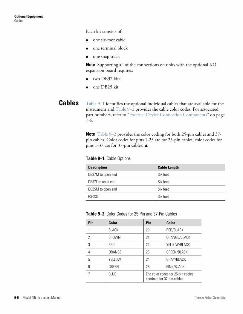
Optional Equipment Cables
9-6 Model 48i Instruction Manual Thermo Fisher Scientific
Each kit consists of:
● one six-foot cable
● one terminal block
● one snap track
Note Supporting all of the connections on units with the optional I/O expansion board requires:
● two DB37 kits
● one DB25 kit
Table 9–1 identifies the optional individual cables that are available for the instrument and Table 9–2 provides the cable color codes. For associated part numbers, refer to “External Device Connection Components” on page 7-6.
Note Table 9–2 provides the color coding for both 25-pin cables and 37-pin cables. Color codes for pins 1-25 are for 25-pin cables; color codes for pins 1-37 are for 37-pin cables. ▲
Table 9–1. Cable Options
Description Cable Length
DB37M to open end Six feet
DB37F to open end Six feet
DB25M to open end Six feet
RS-232 Six feet
Table 9–2. Color Codes for 25-Pin and 37-Pin Cables
Pin Color Pin Color
1 BLACK 20 RED/BLACK
2 BROWN 21 ORANGE/BLACK
3 RED 22 YELLOW/BLACK
4 ORANGE 23 GREEN/BLACK
5 YELLOW 24 GRAY/BLACK
6 GREEN 25 PINK/BLACK
7 BLUE End color codes for 25-pin cables continue for 37-pin cables.
Cables
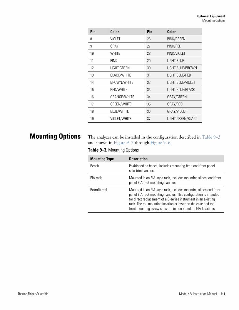
Optional Equipment Mounting Options
Thermo Fisher Scientific Model 48i Instruction Manual 9-7
Pin Color Pin Color
8 VIOLET 26 PINK/GREEN
9 GRAY 27 PINK/RED
19 WHITE 28 PINK/VIOLET
11 PINK 29 LIGHT BLUE
12 LIGHT GREEN 30 LIGHT BLUE/BROWN
13 BLACK/WHITE 31 LIGHT BLUE/RED
14 BROWN/WHITE 32 LIGHT BLUE/VIOLET
15 RED/WHITE 33 LIGHT BLUE/BLACK
16 ORANGE/WHITE 34 GRAY/GREEN
17 GREEN/WHITE 35 GRAY/RED
18 BLUE/WHITE 36 GRAY/VIOLET
19 VIOLET/WHITE 37 LIGHT GREEN/BLACK
The analyzer can be installed in the configuration described in Table 9–3 and shown in Figure 9–3 through Figure 9–6.
Table 9–3. Mounting Options
Mounting Type Description
Bench Positioned on bench, includes mounting feet, and front panel side-trim handles.
EIA rack Mounted in an EIA-style rack, includes mounting slides, and front panel EIA-rack mounting handles.
Retrofit rack Mounted in an EIA-style rack, includes mounting slides and front panel EIA-rack mounting handles. This configuration is intended for direct replacement of a C-series instrument in an existing rack. The rail mounting location is lower on the case and the front mounting screw slots are in non-standard EIA locations.
Mounting Options
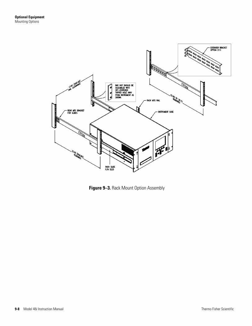
Optional Equipment Mounting Options
9-8 Model 48i Instruction Manual Thermo Fisher Scientific
Figure 9–3. Rack Mount Option Assembly
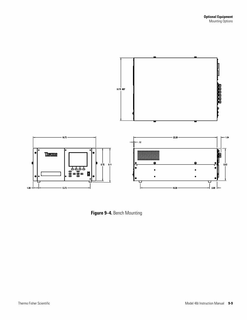
Optional Equipment Mounting Options
Thermo Fisher Scientific Model 48i Instruction Manual 9-9
Figure 9–4. Bench Mounting
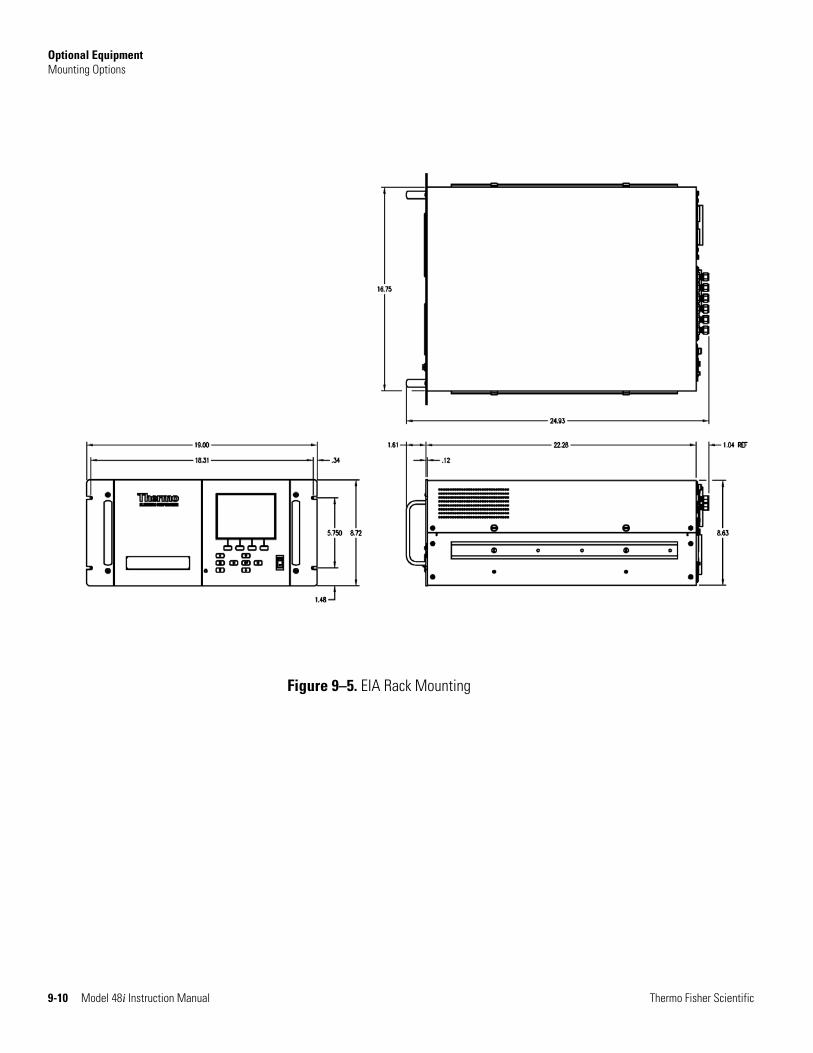
Optional Equipment Mounting Options
9-10 Model 48i Instruction Manual Thermo Fisher Scientific
Figure 9–5. EIA Rack Mounting
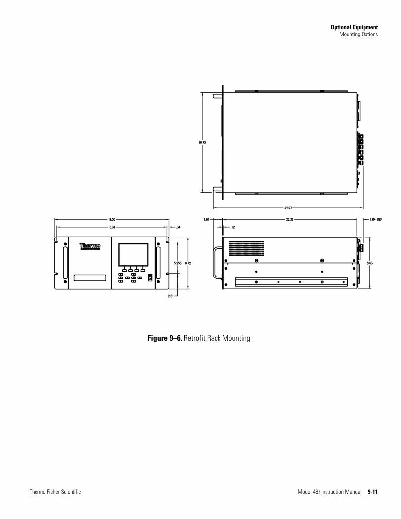
Optional Equipment Mounting Options
Thermo Fisher Scientific Model 48i Instruction Manual 9-11
Figure 9–6. Retrofit Rack Mounting


Thermo Fisher Scientific Model 48i Instruction Manual A-1
Appendix A Warranty
Seller warrants that the Products will operate or perform substantially in conformance with Seller's published specifications and be free from defects in material and workmanship, when subjected to normal, proper and intended usage by properly trained personnel, for the period of time set forth in the product documentation, published specifications or package inserts. If a period of time is not specified in Seller’s product documentation, published specifications or package inserts, the warranty period shall be one (1) year from the date of shipment to Buyer for equipment and ninety (90) days for all other products (the "Warranty Period"). Seller agrees during the Warranty Period, to repair or replace, at Seller's option, defective Products so as to cause the same to operate in substantial conformance with said published specifications; provided that (a) Buyer shall promptly notify Seller in writing upon the discovery of any defect, which notice shall include the product model and serial number (if applicable) and details of the warranty claim; (b) after Seller’s review, Seller will provide Buyer with service data and/or a Return Material Authorization (“RMA”), which may include biohazard decontamination procedures and other product-specific handling instructions; and (c) then, if applicable, Buyer may return the defective Products to Seller with all costs prepaid by Buyer. Replacement parts may be new or refurbished, at the election of Seller. All replaced parts shall become the property of Seller. Shipment to Buyer of repaired or replacement Products shall be made in accordance with the Delivery provisions of the Seller’s Terms and Conditions of Sale. Consumables, including but not limited to lamps, fuses, batteries, bulbs and other such expendable items, are expressly excluded from the warranty under this warranty.
Notwithstanding the foregoing, Products supplied by Seller that are obtained by Seller from an original manufacturer or third party supplier are not warranted by Seller, but Seller agrees to assign to Buyer any warranty rights in such Product that Seller may have from the original manufacturer or third party supplier, to the extent such assignment is allowed by such original manufacturer or third party supplier.
In no event shall Seller have any obligation to make repairs, replacements or corrections required, in whole or in part, as the result of (i) normal wear and tear, (ii) accident, disaster or event of force majeure, (iii) misuse, fault or negligence of or by Buyer, (iv) use of the Products in a manner for which
Warranty
Warranty Warranty
A-2 Model 48i Instruction Manual Thermo Fisher Scientific
they were not designed, (v) causes external to the Products such as, but not limited to, power failure or electrical power surges, (vi) improper storage and handling of the Products or (vii) use of the Products in combination with equipment or software not supplied by Seller. If Seller determines that Products for which Buyer has requested warranty services are not covered by the warranty hereunder, Buyer shall pay or reimburse Seller for all costs of investigating and responding to such request at Seller's then prevailing time and materials rates. If Seller provides repair services or replacement parts that are not covered by the warranty provided in this warranty, Buyer shall pay Seller therefor at Seller's then prevailing time and materials rates. ANY INSTALLATION, MAINTENANCE, REPAIR, SERVICE, RELOCATION OR ALTERATION TO OR OF, OR OTHER TAMPERING WITH, THE PRODUCTS PERFORMED BY ANY PERSON OR ENTITY OTHER THAN SELLER WITHOUT SELLER'S PRIOR WRITTEN APPROVAL, OR ANY USE OF REPLACEMENT PARTS NOT SUPPLIED BY SELLER, SHALL IMMEDIATELY VOID AND CANCEL ALL WARRANTIES WITH RESPECT TO THE AFFECTED PRODUCTS.
THE OBLIGATIONS CREATED BY THIS WARRANTY STATEMENT TO REPAIR OR REPLACE A DEFECTIVE PRODUCT SHALL BE THE SOLE REMEDY OF BUYER IN THE EVENT OF A DEFECTIVE PRODUCT. EXCEPT AS EXPRESSLY PROVIDED IN THIS WARRANTY STATEMENT, SELLER DISCLAIMS ALL OTHER WARRANTIES, WHETHER EXPRESS OR IMPLIED, ORAL OR WRITTEN, WITH RESPECT TO THE PRODUCTS, INCLUDING WITHOUT LIMITATION ALL IMPLIED WARRANTIES OF MERCHANTABILITY OR FITNESS FOR ANY PARTICULAR PURPOSE. SELLER DOES NOT WARRANT THAT THE PRODUCTS ARE ERROR-FREE OR WILL ACCOMPLISH ANY PARTICULAR RESULT.
Thermo Fisher Scientific Model 48i Instruction Manual B-1
Appendix B C-Link Protocol Commands
This appendix provides a description of the C-Link protocol commands that can be used to remotely control a Model 48i analyzer using a host device such as a PC or a datalogger. C-Link protocol may be used over RS-232, RS-485, or Ethernet. C-Link functions can be accessed over Ethernet using TCP port 9880.
Streaming data is sent out the serial port or the Ethernet port on a user-defined periodic basis. Streaming data over Ethernet is only generated when a connection is made on TCP port 9881.
Up to three simultaneous connections per protocol may be made over Ethernet.
For details, see the following topics:
● “Instrument Identification Number” on page B-1
● “Commands” on page B-2
● “Measurements” on page B-10
● “Alarms” on page B-14
● “Diagnostics” on page B-18
● “Datalogging” on page B-19
● “Calibration” on page B-26
● “Keys/Display” on page B-33
● “Measurement Configuration” on page B-35
● “Hardware Configuration” on page B-38
● “Communications Configuration” on page B-40
● “I/O Configuration” on page B-47
● “Record Layout Definition” on page B-53
Each command sent to the analyzer over the serial port must begin with the American Standard Code for Information Interchange (ASCII) symbol or byte value equivalent to the instrument's identification number plus 128.
Instrument Identification
Number
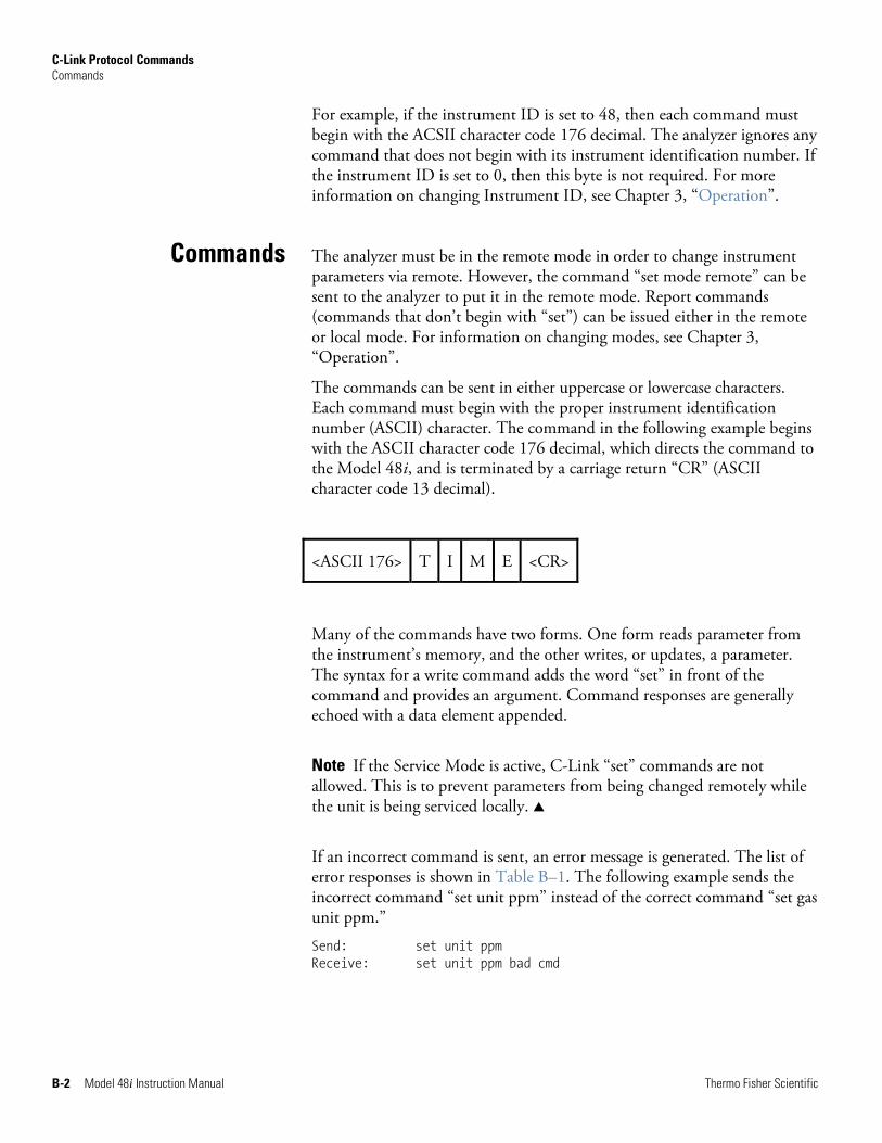
C-Link Protocol Commands Commands
B-2 Model 48i Instruction Manual Thermo Fisher Scientific
For example, if the instrument ID is set to 48, then each command must begin with the ACSII character code 176 decimal. The analyzer ignores any command that does not begin with its instrument identification number. If the instrument ID is set to 0, then this byte is not required. For more information on changing Instrument ID, see Chapter 3, “Operation”.
The analyzer must be in the remote mode in order to change instrument parameters via remote. However, the command “set mode remote” can be sent to the analyzer to put it in the remote mode. Report commands (commands that don’t begin with “set”) can be issued either in the remote or local mode. For information on changing modes, see Chapter 3, “Operation”.
The commands can be sent in either uppercase or lowercase characters. Each command must begin with the proper instrument identification number (ASCII) character. The command in the following example begins with the ASCII character code 176 decimal, which directs the command to the Model 48i, and is terminated by a carriage return “CR” (ASCII character code 13 decimal).
<ASCII 176> T I M E <CR>
Many of the commands have two forms. One form reads parameter from the instrument’s memory, and the other writes, or updates, a parameter. The syntax for a write command adds the word “set” in front of the command and provides an argument. Command responses are generally echoed with a data element appended.
Note If the Service Mode is active, C-Link “set” commands are not allowed. This is to prevent parameters from being changed remotely while the unit is being serviced locally. ▲
If an incorrect command is sent, an error message is generated. The list of error responses is shown in Table B–1. The following example sends the incorrect command “set unit ppm” instead of the correct command “set gas unit ppm.”
Send: set unit ppm Receive: set unit ppm bad cmd
Commands
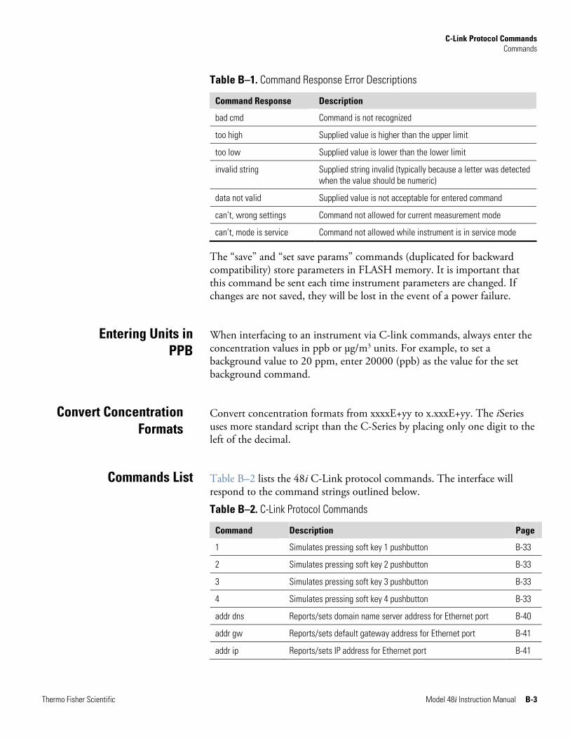
C-Link Protocol Commands Commands
Thermo Fisher Scientific Model 48i Instruction Manual B-3
Table B–1. Command Response Error Descriptions
Command Response Description
bad cmd Command is not recognized
too high Supplied value is higher than the upper limit
too low Supplied value is lower than the lower limit
invalid string Supplied string invalid (typically because a letter was detected when the value should be numeric)
data not valid Supplied value is not acceptable for entered command
can’t, wrong settings Command not allowed for current measurement mode
can’t, mode is service Command not allowed while instrument is in service mode
The “save” and “set save params” commands (duplicated for backward compatibility) store parameters in FLASH memory. It is important that this command be sent each time instrument parameters are changed. If changes are not saved, they will be lost in the event of a power failure.
When interfacing to an instrument via C-link commands, always enter the concentration values in ppb or μg/m3 units. For example, to set a background value to 20 ppm, enter 20000 (ppb) as the value for the set background command.
Convert concentration formats from xxxxE+yy to x.xxxE+yy. The iSeries uses more standard script than the C-Series by placing only one digit to the left of the decimal.
Table B–2 lists the 48i C-Link protocol commands. The interface will respond to the command strings outlined below.
Table B–2. C-Link Protocol Commands
Command Description Page
1 Simulates pressing soft key 1 pushbutton B-33
2 Simulates pressing soft key 2 pushbutton B-33
3 Simulates pressing soft key 3 pushbutton B-33
4 Simulates pressing soft key 4 pushbutton B-33
addr dns Reports/sets domain name server address for Ethernet port B-40
addr gw Reports/sets default gateway address for Ethernet port B-41
addr ip Reports/sets IP address for Ethernet port B-41
Entering Units in PPB
Convert Concentration Formats
Commands List
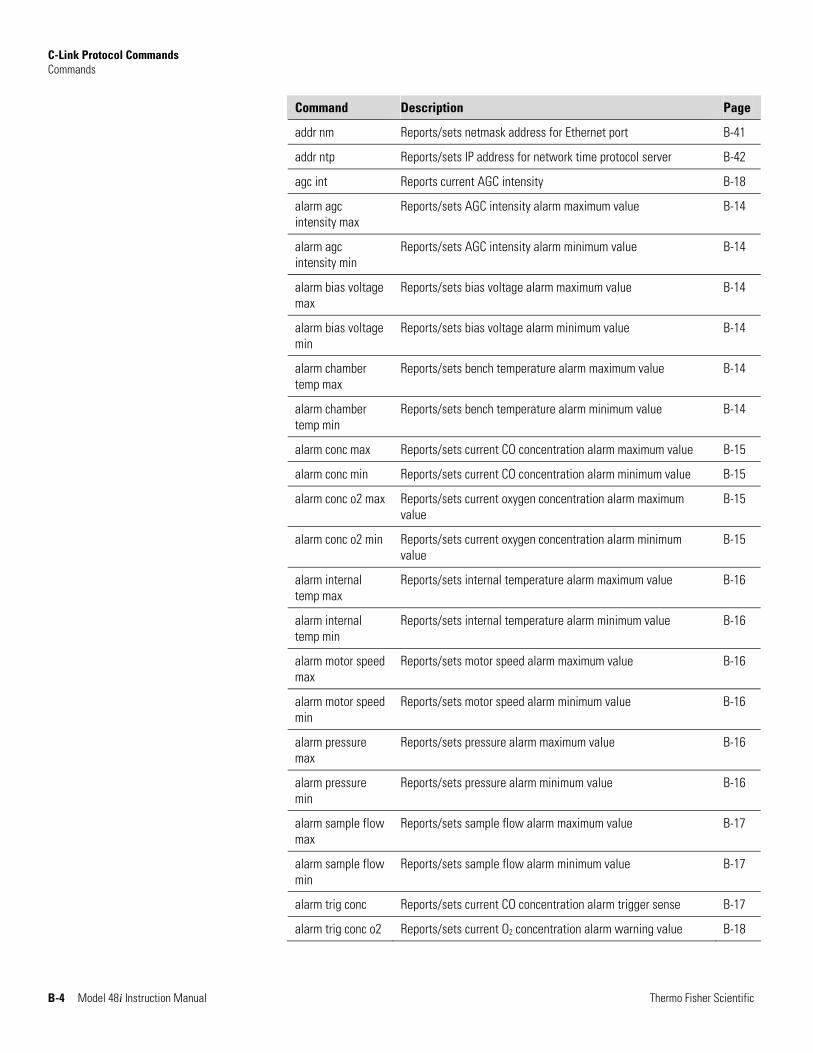
C-Link Protocol Commands Commands
B-4 Model 48i Instruction Manual Thermo Fisher Scientific
Command Description Page
addr nm Reports/sets netmask address for Ethernet port B-41
addr ntp Reports/sets IP address for network time protocol server B-42
agc int Reports current AGC intensity B-18
alarm agc intensity max
Reports/sets AGC intensity alarm maximum value B-14
alarm agc intensity min
Reports/sets AGC intensity alarm minimum value B-14
alarm bias voltage max
Reports/sets bias voltage alarm maximum value B-14
alarm bias voltage min
Reports/sets bias voltage alarm minimum value B-14
alarm chamber temp max
Reports/sets bench temperature alarm maximum value B-14
alarm chamber temp min
Reports/sets bench temperature alarm minimum value B-14
alarm conc max Reports/sets current CO concentration alarm maximum value B-15
alarm conc min Reports/sets current CO concentration alarm minimum value B-15
alarm conc o2 max Reports/sets current oxygen concentration alarm maximum value
B-15
alarm conc o2 min Reports/sets current oxygen concentration alarm minimum value
B-15
alarm internal temp max
Reports/sets internal temperature alarm maximum value B-16
alarm internal temp min
Reports/sets internal temperature alarm minimum value B-16
alarm motor speed max
Reports/sets motor speed alarm maximum value B-16
alarm motor speed min
Reports/sets motor speed alarm minimum value B-16
alarm pressure max
Reports/sets pressure alarm maximum value B-16
alarm pressure min
Reports/sets pressure alarm minimum value B-16
alarm sample flow max
Reports/sets sample flow alarm maximum value B-17
alarm sample flow min
Reports/sets sample flow alarm minimum value B-17
alarm trig conc Reports/sets current CO concentration alarm trigger sense B-17
alarm trig conc o2 Reports/sets current O2 concentration alarm warning value B-18
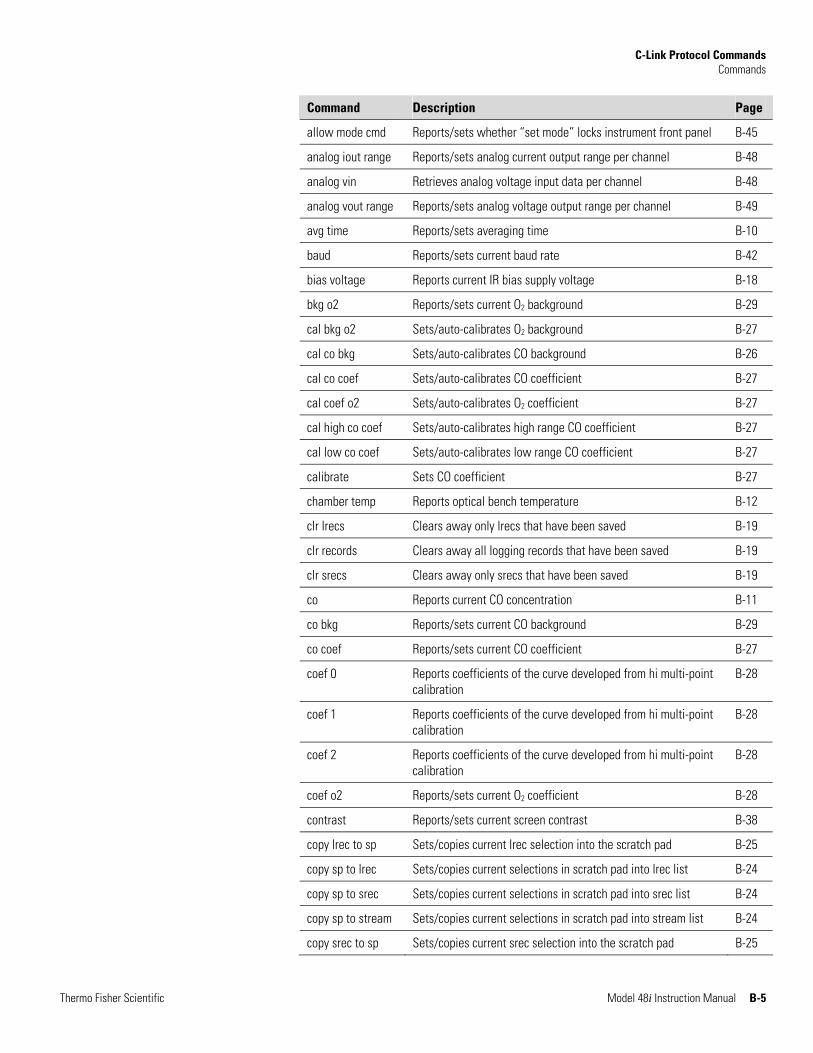
C-Link Protocol Commands Commands
Thermo Fisher Scientific Model 48i Instruction Manual B-5
Command Description Page
allow mode cmd Reports/sets whether “set mode” locks instrument front panel B-45
analog iout range Reports/sets analog current output range per channel B-48
analog vin Retrieves analog voltage input data per channel B-48
analog vout range Reports/sets analog voltage output range per channel B-49
avg time Reports/sets averaging time B-10
baud Reports/sets current baud rate B-42
bias voltage Reports current IR bias supply voltage B-18
bkg o2 Reports/sets current O2 background B-29
cal bkg o2 Sets/auto-calibrates O2 background B-27
cal co bkg Sets/auto-calibrates CO background B-26
cal co coef Sets/auto-calibrates CO coefficient B-27
cal coef o2 Sets/auto-calibrates O2 coefficient B-27
cal high co coef Sets/auto-calibrates high range CO coefficient B-27
cal low co coef Sets/auto-calibrates low range CO coefficient B-27
calibrate Sets CO coefficient B-27
chamber temp Reports optical bench temperature B-12
clr lrecs Clears away only lrecs that have been saved B-19
clr records Clears away all logging records that have been saved B-19
clr srecs Clears away only srecs that have been saved B-19
co Reports current CO concentration B-11
co bkg Reports/sets current CO background B-29
co coef Reports/sets current CO coefficient B-27
coef 0 Reports coefficients of the curve developed from hi multi-point calibration
B-28
coef 1 Reports coefficients of the curve developed from hi multi-point calibration
B-28
coef 2 Reports coefficients of the curve developed from hi multi-point calibration
B-28
coef o2 Reports/sets current O2 coefficient B-28
contrast Reports/sets current screen contrast B-38
copy lrec to sp Sets/copies current lrec selection into the scratch pad B-25
copy sp to lrec Sets/copies current selections in scratch pad into lrec list B-24
copy sp to srec Sets/copies current selections in scratch pad into srec list B-24
copy sp to stream Sets/copies current selections in scratch pad into stream list B-24
copy srec to sp Sets/copies current srec selection into the scratch pad B-25
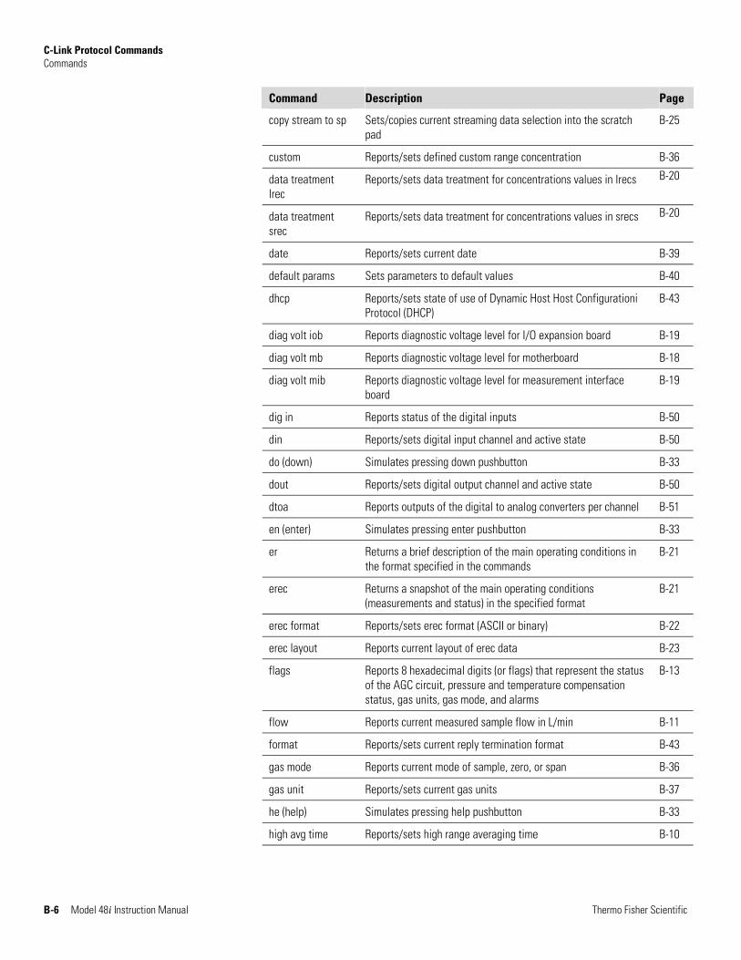
C-Link Protocol Commands Commands
B-6 Model 48i Instruction Manual Thermo Fisher Scientific
Command Description Page
copy stream to sp Sets/copies current streaming data selection into the scratch pad
B-25
custom Reports/sets defined custom range concentration B-36
data treatment lrec
Reports/sets data treatment for concentrations values in lrecs B-20
data treatment srec
Reports/sets data treatment for concentrations values in srecs B-20
date Reports/sets current date B-39
default params Sets parameters to default values B-40
dhcp Reports/sets state of use of Dynamic Host Host Configurationi Protocol (DHCP)
B-43
diag volt iob Reports diagnostic voltage level for I/O expansion board B-19
diag volt mb Reports diagnostic voltage level for motherboard B-18
diag volt mib Reports diagnostic voltage level for measurement interface board
B-19
dig in Reports status of the digital inputs B-50
din Reports/sets digital input channel and active state B-50
do (down) Simulates pressing down pushbutton B-33
dout Reports/sets digital output channel and active state B-50
dtoa Reports outputs of the digital to analog converters per channel B-51
en (enter) Simulates pressing enter pushbutton B-33
er Returns a brief description of the main operating conditions in the format specified in the commands
B-21
erec Returns a snapshot of the main operating conditions (measurements and status) in the specified format
B-21
erec format Reports/sets erec format (ASCII or binary) B-22
erec layout Reports current layout of erec data B-23
flags Reports 8 hexadecimal digits (or flags) that represent the status of the AGC circuit, pressure and temperature compensation status, gas units, gas mode, and alarms
B-13
flow Reports current measured sample flow in L/min B-11
format Reports/sets current reply termination format B-43
gas mode Reports current mode of sample, zero, or span B-36
gas unit Reports/sets current gas units B-37
he (help) Simulates pressing help pushbutton B-33
high avg time Reports/sets high range averaging time B-10
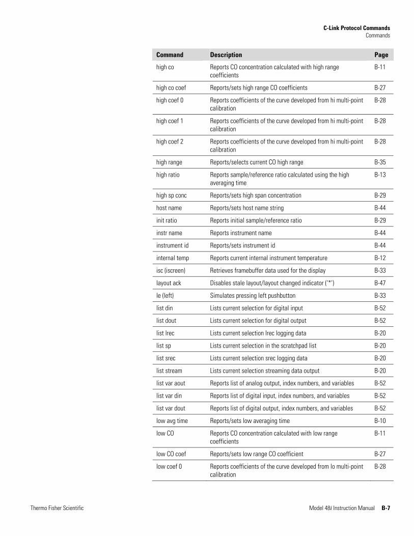
C-Link Protocol Commands Commands
Thermo Fisher Scientific Model 48i Instruction Manual B-7
Command Description Page
high co Reports CO concentration calculated with high range coefficients
B-11
high co coef Reports/sets high range CO coefficients B-27
high coef 0 Reports coefficients of the curve developed from hi multi-point calibration
B-28
high coef 1 Reports coefficients of the curve developed from hi multi-point calibration
B-28
high coef 2 Reports coefficients of the curve developed from hi multi-point calibration
B-28
high range Reports/selects current CO high range B-35
high ratio Reports sample/reference ratio calculated using the high averaging time
B-13
high sp conc Reports/sets high span concentration B-29
host name Reports/sets host name string B-44
init ratio Reports initial sample/reference ratio B-29
instr name Reports instrument name B-44
instrument id Reports/sets instrument id B-44
internal temp Reports current internal instrument temperature B-12
isc (iscreen) Retrieves framebuffer data used for the display B-33
layout ack Disables stale layout/layout changed indicator (‘*’) B-47
le (left) Simulates pressing left pushbutton B-33
list din Lists current selection for digital input B-52
list dout Lists current selection for digital output B-52
list lrec Lists current selection lrec logging data B-20
list sp Lists current selection in the scratchpad list B-20
list srec Lists current selection srec logging data B-20
list stream Lists current selection streaming data output B-20
list var aout Reports list of analog output, index numbers, and variables B-52
list var din Reports list of digital input, index numbers, and variables B-52
list var dout Reports list of digital output, index numbers, and variables B-52
low avg time Reports/sets low averaging time B-10
low CO Reports CO concentration calculated with low range coefficients
B-11
low CO coef Reports/sets low range CO coefficient B-27
low coef 0 Reports coefficients of the curve developed from lo multi-point calibration
B-28
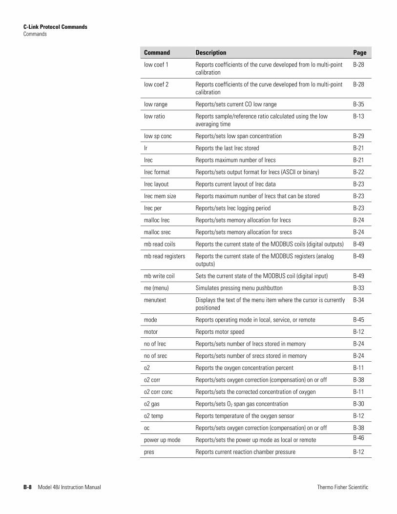
C-Link Protocol Commands Commands
B-8 Model 48i Instruction Manual Thermo Fisher Scientific
Command Description Page
low coef 1 Reports coefficients of the curve developed from lo multi-point calibration
B-28
low coef 2 Reports coefficients of the curve developed from lo multi-point calibration
B-28
low range Reports/sets current CO low range B-35
low ratio Reports sample/reference ratio calculated using the low averaging time
B-13
low sp conc Reports/sets low span concentration B-29
lr Reports the last lrec stored B-21
lrec Reports maximum number of lrecs B-21
lrec format Reports/sets output format for lrecs (ASCII or binary) B-22
lrec layout Reports current layout of lrec data B-23
lrec mem size Reports maximum number of lrecs that can be stored B-23
lrec per Reports/sets lrec logging period B-23
malloc lrec Reports/sets memory allocation for lrecs B-24
malloc srec Reports/sets memory allocation for srecs B-24
mb read coils Reports the current state of the MODBUS coils (digital outputs) B-49
mb read registers Reports the current state of the MODBUS registers (analog outputs)
B-49
mb write coil Sets the current state of the MODBUS coil (digital input) B-49
me (menu) Simulates pressing menu pushbutton B-33
menutext Displays the text of the menu item where the cursor is currently positioned
B-34
mode Reports operating mode in local, service, or remote B-45
motor Reports motor speed B-12
no of lrec Reports/sets number of lrecs stored in memory B-24
no of srec Reports/sets number of srecs stored in memory B-24
o2 Reports the oxygen concentration percent B-11
o2 corr Reports/sets oxygen correction (compensation) on or off B-38
o2 corr conc Reports/sets the corrected concentration of oxygen B-11
o2 gas Reports/sets O2 span gas concentration B-30
o2 temp Reports temperature of the oxygen sensor B-12
oc Reports/sets oxygen correction (compensation) on or off B-38
power up mode Reports/sets the power up mode as local or remote B-46
pres Reports current reaction chamber pressure B-12
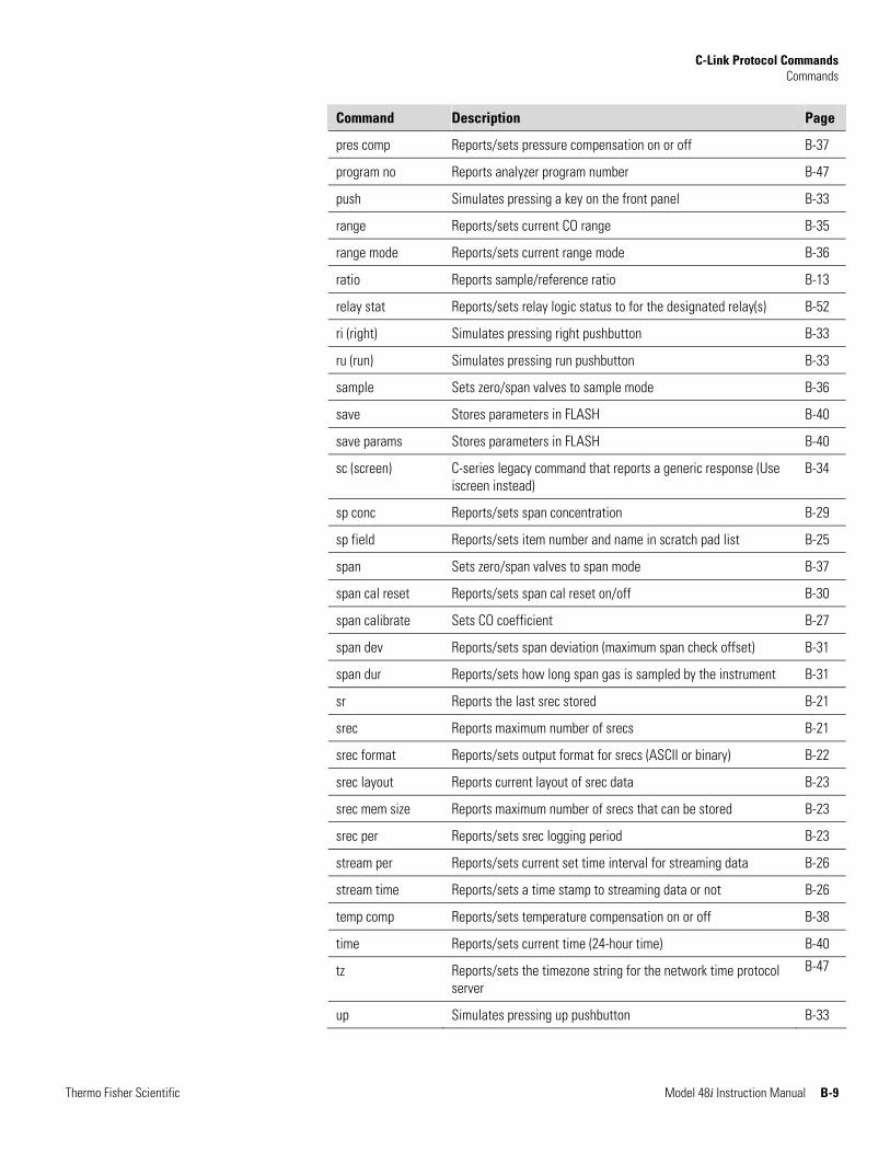
C-Link Protocol Commands Commands
Thermo Fisher Scientific Model 48i Instruction Manual B-9
Command Description Page
pres comp Reports/sets pressure compensation on or off B-37
program no Reports analyzer program number B-47
push Simulates pressing a key on the front panel B-33
range Reports/sets current CO range B-35
range mode Reports/sets current range mode B-36
ratio Reports sample/reference ratio B-13
relay stat Reports/sets relay logic status to for the designated relay(s) B-52
ri (right) Simulates pressing right pushbutton B-33
ru (run) Simulates pressing run pushbutton B-33
sample Sets zero/span valves to sample mode B-36
save Stores parameters in FLASH B-40
save params Stores parameters in FLASH B-40
sc (screen) C-series legacy command that reports a generic response (Use iscreen instead)
B-34
sp conc Reports/sets span concentration B-29
sp field Reports/sets item number and name in scratch pad list B-25
span Sets zero/span valves to span mode B-37
span cal reset Reports/sets span cal reset on/off B-30
span calibrate Sets CO coefficient B-27
span dev Reports/sets span deviation (maximum span check offset) B-31
span dur Reports/sets how long span gas is sampled by the instrument B-31
sr Reports the last srec stored B-21
srec Reports maximum number of srecs B-21
srec format Reports/sets output format for srecs (ASCII or binary) B-22
srec layout Reports current layout of srec data B-23
srec mem size Reports maximum number of srecs that can be stored B-23
srec per Reports/sets srec logging period B-23
stream per Reports/sets current set time interval for streaming data B-26
stream time Reports/sets a time stamp to streaming data or not B-26
temp comp Reports/sets temperature compensation on or off B-38
time Reports/sets current time (24-hour time) B-40
tz Reports/sets the timezone string for the network time protocol server
B-47
up Simulates pressing up pushbutton B-33
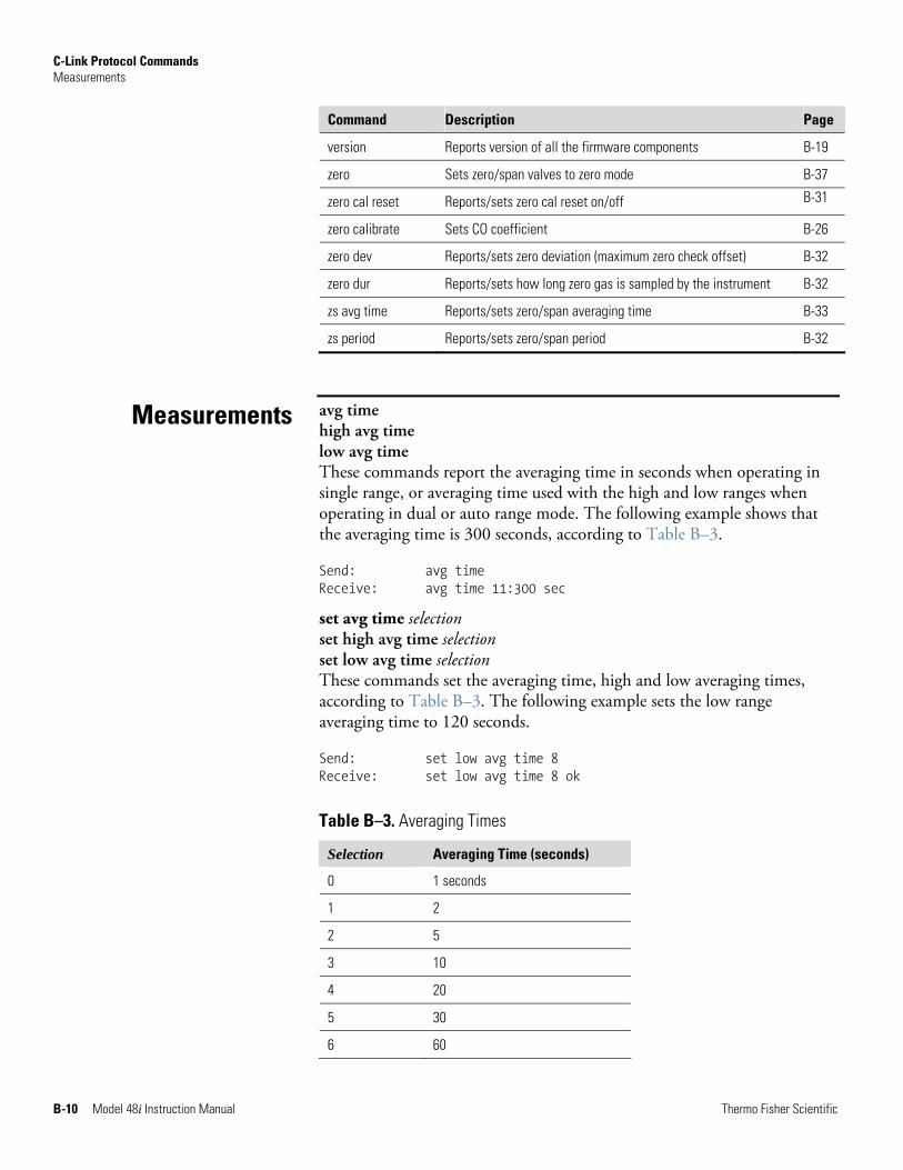
C-Link Protocol Commands Measurements
B-10 Model 48i Instruction Manual Thermo Fisher Scientific
Command Description Page
version Reports version of all the firmware components B-19
zero Sets zero/span valves to zero mode B-37
zero cal reset Reports/sets zero cal reset on/off B-31
zero calibrate Sets CO coefficient B-26
zero dev Reports/sets zero deviation (maximum zero check offset) B-32
zero dur Reports/sets how long zero gas is sampled by the instrument B-32
zs avg time Reports/sets zero/span averaging time B-33
zs period Reports/sets zero/span period B-32
avg time high avg time low avg time These commands report the averaging time in seconds when operating in single range, or averaging time used with the high and low ranges when operating in dual or auto range mode. The following example shows that the averaging time is 300 seconds, according to Table B–3.
Send: avg time Receive: avg time 11:300 sec
set avg time selection set high avg time selection set low avg time selection These commands set the averaging time, high and low averaging times, according to Table B–3. The following example sets the low range averaging time to 120 seconds.
Send: set low avg time 8 Receive: set low avg time 8 ok
Table B–3. Averaging Times
Selection Averaging Time (seconds)
0 1 seconds
1 2
2 5
3 10
4 20
5 30
6 60
Measurements
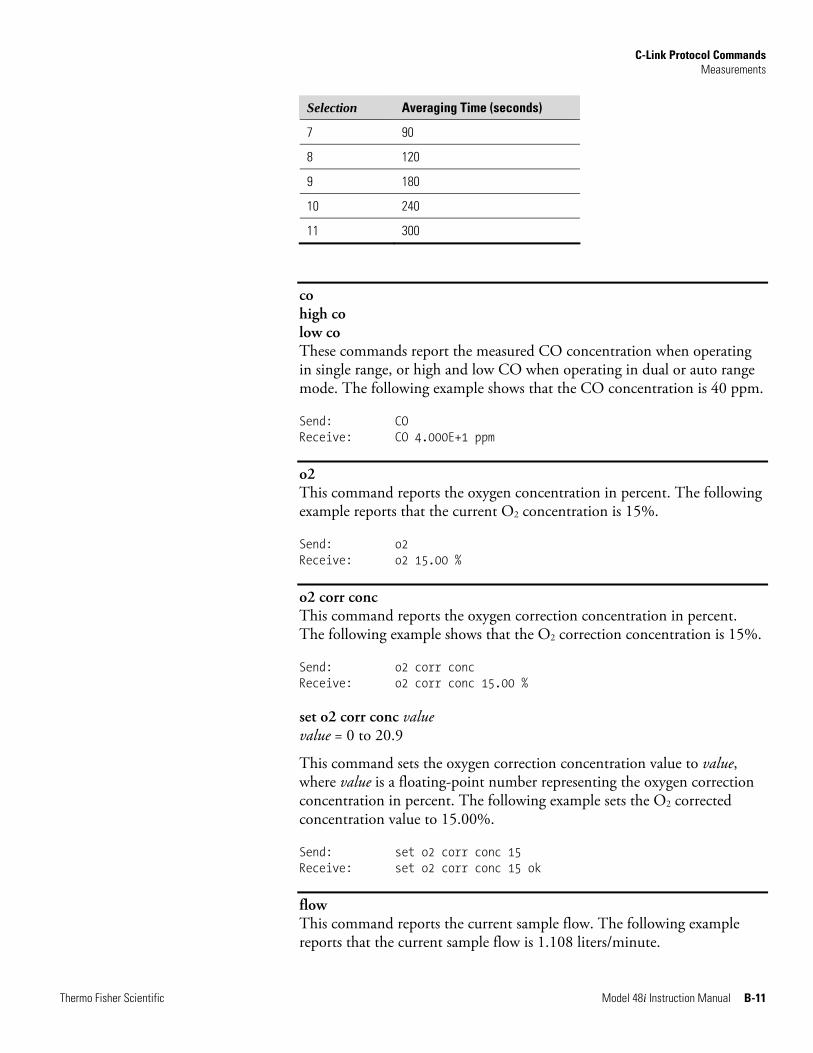
C-Link Protocol Commands Measurements
Thermo Fisher Scientific Model 48i Instruction Manual B-11
Selection Averaging Time (seconds)
7 90
8 120
9 180
10 240
11 300
co high co low co These commands report the measured CO concentration when operating in single range, or high and low CO when operating in dual or auto range mode. The following example shows that the CO concentration is 40 ppm.
Send: CO Receive: CO 4.000E+1 ppm
o2 This command reports the oxygen concentration in percent. The following example reports that the current O2 concentration is 15%.
Send: o2 Receive: o2 15.00 %
o2 corr conc This command reports the oxygen correction concentration in percent. The following example shows that the O2 correction concentration is 15%.
Send: o2 corr conc Receive: o2 corr conc 15.00 % set o2 corr conc value value = 0 to 20.9
This command sets the oxygen correction concentration value to value, where value is a floating-point number representing the oxygen correction concentration in percent. The following example sets the O2 corrected concentration value to 15.00%.
Send: set o2 corr conc 15 Receive: set o2 corr conc 15 ok
flow This command reports the current sample flow. The following example reports that the current sample flow is 1.108 liters/minute.
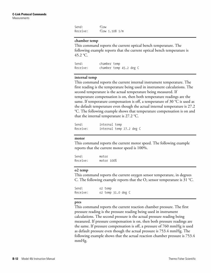
C-Link Protocol Commands Measurements
B-12 Model 48i Instruction Manual Thermo Fisher Scientific
Send: flow Receive: flow 1.108 1/m
chamber temp This command reports the current optical bench temperature. The following example reports that the current optical bench temperature is 45.2 °C.
Send: chamber temp Receive: chamber temp 45.2 deg C
internal temp This command reports the current internal instrument temperature. The first reading is the temperature being used in instrument calculations. The second temperature is the actual temperature being measured. If temperature compensation is on, then both temperature readings are the same. If temperature compensation is off, a temperature of 30 °C is used as the default temperature even though the actual internal temperature is 27.2 °C. The following example shows that temperature compensation is on and that the internal temperature is 27.2 °C.
Send: internal temp Receive: internal temp 27.2 deg C
motor This command reports the current motor speed. The following example reports that the current motor speed is 100%.
Send: motor Receive: motor 100%
o2 temp This command reports the current oxygen sensor temperature, in degrees C. The following example reports that the O2 sensor temperature is 31 °C.
Send: o2 temp Receive: o2 temp 31.0 deg C
pres This command reports the current reaction chamber pressure. The first pressure reading is the pressure reading being used in instrument calculations. The second pressure is the actual pressure reading being measured. If pressure compensation is on, then both pressure readings are the same. If pressure compensation is off, a pressure of 760 mmHg is used as default pressure even though the actual pressure is 753.4 mmHg. The following example shows that the actual reaction chamber pressure is 753.4 mmHg.
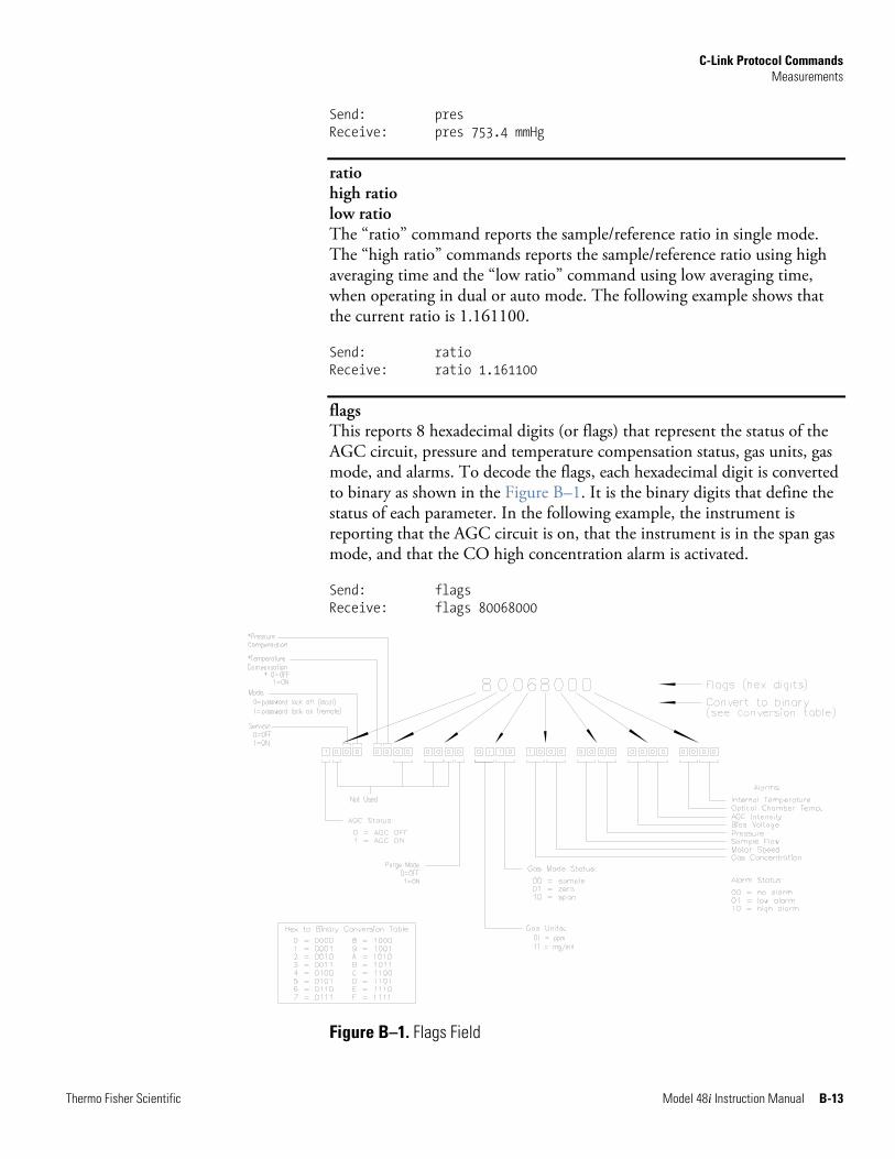
C-Link Protocol Commands Measurements
Thermo Fisher Scientific Model 48i Instruction Manual B-13
Send: pres Receive: pres 753.4 mmHg
ratio high ratio low ratio The “ratio” command reports the sample/reference ratio in single mode. The “high ratio” commands reports the sample/reference ratio using high averaging time and the “low ratio” command using low averaging time, when operating in dual or auto mode. The following example shows that the current ratio is 1.161100.
Send: ratio Receive: ratio 1.161100
flags This reports 8 hexadecimal digits (or flags) that represent the status of the AGC circuit, pressure and temperature compensation status, gas units, gas mode, and alarms. To decode the flags, each hexadecimal digit is converted to binary as shown in the Figure B–1. It is the binary digits that define the status of each parameter. In the following example, the instrument is reporting that the AGC circuit is on, that the instrument is in the span gas mode, and that the CO high concentration alarm is activated.
Send: flags Receive: flags 80068000
Figure B–1. Flags Field
C-Link Protocol Commands Alarms
B-14 Model 48i Instruction Manual Thermo Fisher Scientific
alarm agc intensity min alarm agc intensity max These commands report the agc intensity alarm minimum and maximum value current settings. The following example reports that the agc intensity alarm minimum value is 20.
Send: alarm agc intensity min Receive: alarm agc intensity min 20 set alarm agc intensity min value set alarm agc intensity max value These commands set the agc intensity alarm minimum and maximum values to value, where value is a floating-point number representing agc intensity alarm limits. The following example sets the agc intensity alarm maximum value to 20.
Send: set alarm agc intensity max 20 Receive: set alarm agc intensity max 20 ok
alarm bias voltage min alarm bias voltage max These commands report the bias voltage alarm minimum and maximum value current settings. The following example reports that the bias voltage alarm minimum value is -128.
Send: alarm bias voltage min Receive: alarm bias voltage min -128 set alarm bias voltage min value set alarm bias voltage max value These commands set the bias voltage alarm minimum and maximum values to value, where value is a floating-point number representing bias voltage alarm limits. The following example sets the bias voltage alarm maximum value to -110.
Send: set alarm bias voltage max -110 Receive: set alarm bias voltage max -110 ok
alarm chamber temp min alarm chamber temp max These commands report the bench temperature alarm minimum and maximum value current settings. The following example reports that the bench temperature alarm minimum value is 35.0 °C.
Send: alarm chamber temp min Receive: alarm chamber temp min 35.0 deg C
Alarms
C-Link Protocol Commands Alarms
Thermo Fisher Scientific Model 48i Instruction Manual B-15
set alarm chamber temp min value set alarm chamber temp max value These commands set the bench temperature alarm minimum and maximum values to value, where value is a floating-point number representing bench temperature alarm limits in degrees C. The following example sets the bench temperature alarm maximum value to 55.0 °C.
Send: set alarm chamber temp max 55.0 Receive: set alarm chamber temp max 55.0 ok
alarm conc min alarm conc max These commands report the CO concentration alarm minimum and maximum values current setting. The following example reports that the CO concentration minimum is 5.2 ppm.
Send: alarm conc min Receive: alarm conc min 5.2 ppm set alarm conc min value set alarm conc max value These commands set the CO concentration alarm minimum and maximum values to value, where value is a floating-point representation of the concentration alarm limits. Values must be in the units that are currently set for use. The following example sets the CO concentration alarm maximum value to 215.
Send: set alarm conc max 215 Receive: set alarm conc max 215 ok
alarm conc o2 min alarm conc o2 max These commands report the current oxygen concentration alarm minimum and maximum value settings. The following example reports that the O2 concentration alarm minimum value is 10%.
Send: alarm conc o2 min Receive: alarm conc o2 min 10.00 % set alarm conc o2 min value set alarm conc o2 max value These commands set the oxygen concentration alarm minimum and maximum values to value, where value is a floating-point number representing the oxygen concentration alarm limits in percent. The following example sets the O2 concentration alarm maximum value to 100.00%.
C-Link Protocol Commands Alarms
B-16 Model 48i Instruction Manual Thermo Fisher Scientific
Send: set alarm conc o2 max 100 Receive: set alarm conc o2 max 100 ok
alarm internal temp min alarm internal temp max These commands report the internal temperature alarm minimum and maximum value current settings. The following example reports that the internal temperature alarm minimum value is 15.0 °C.
Send: alarm internal temp min Receive: alarm internal temp min 15.0 deg C set alarm internal temp min value set alarm internal temp max value These commands set the internal temperature alarm minimum and maximum values to value, where value is a floating-point number representing internal temperature alarm limits in degrees C. The following example sets the internal temperature alarm maximum value to 45.0 °C.
Send: set alarm internal temp max 45 Receive: set alarm internal temp max 45 ok
alarm motor speed min alarm motor speed max These commands report the motor speed alarm minimum and maximum value current settings. The following example reports that the motor speed alarm minimum value is 99.8 %.
Send: alarm motor speed min Receive: alarm motor speed min 99.8 set alarm motor speed min value set alarm motor speed max value These commands set the motor speed alarm minimum and maximum values to value, where value is a floating-point number representing motor speed alarm limits in minutes. The following example sets the motor speed alarm maximum value to 100.2 %.
Send: set alarm motor speed max 100.2 Receive: set alarm motor speed max 100.2 ok
alarm pressure min alarm pressure max These commands report the pressure alarm minimum and maximum value current settings. The following example reports that the pressure alarm minimum value is 650 mmHg.
C-Link Protocol Commands Alarms
Thermo Fisher Scientific Model 48i Instruction Manual B-17
Send: alarm pressure min Receive: alarm pressure min 650 mmHg set alarm pressure min value set alarm pressure max value These commands set the pressure alarm minimum and maximum values to value, where value is a floating-point number representing pressure alarm limits in millimeters of mercury. The following example sets the pressure alarm maximum value to 790 mmHg.
Send: set alarm pressure max 790 Receive: set alarm pressure max 790 ok
alarm sample flow min alarm sample flow max These commands report the sample flow alarm minimum and maximum value current settings. The following example reports that the sample flow alarm minimum value is 0.350 L/min.
Send: alarm sample flow min Receive: alarm sample flow min 0.350 l/min set alarm sample flow min value set alarm sample flow max value These commands set the sample flow alarm minimum and maximum values to value, where value is a floating-point number representing sample flow alarm limits in liters per minute. The following example sets the sample flow alarm maximum value to 1 L/min.
Send: set alarm sample flow max 1.000 Receive: set alarm sample flow max 1.000 ok
alarm trig conc This command reports the CO concentration alarm trigger action for minimum alarm, current setting, to either floor or ceiling. The following example shows the CO concentration minimum alarm trigger to ceiling, according to Table B–4.
Send: alarm trig conc Receive: alarm trig conc 1 set alarm trig conc value This command sets the CO concentration alarm minimum value, where value is set to either floor or ceiling, according to Table B–4. The following example sets the CO concentration minimum alarm trigger to ceiling.
Send: set alarm trig conc 1 Receive: set alarm trig conc 1 ok
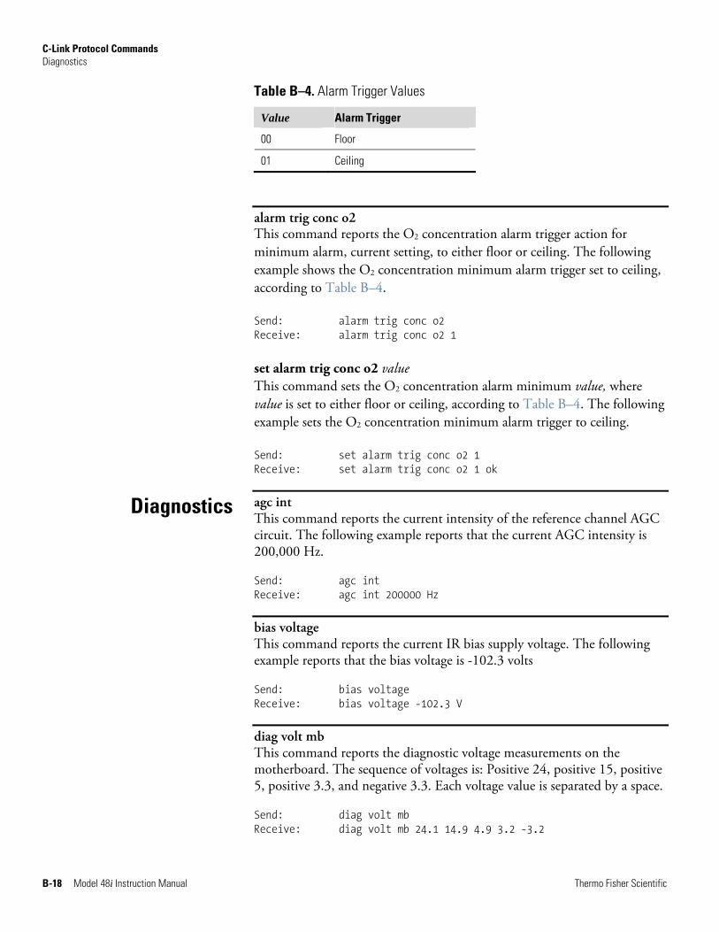
C-Link Protocol Commands Diagnostics
B-18 Model 48i Instruction Manual Thermo Fisher Scientific
Table B–4. Alarm Trigger Values
Value Alarm Trigger
00 Floor
01 Ceiling
alarm trig conc o2 This command reports the O2 concentration alarm trigger action for minimum alarm, current setting, to either floor or ceiling. The following example shows the O2 concentration minimum alarm trigger set to ceiling, according to Table B–4.
Send: alarm trig conc o2 Receive: alarm trig conc o2 1 set alarm trig conc o2 value This command sets the O2 concentration alarm minimum value, where value is set to either floor or ceiling, according to Table B–4. The following example sets the O2 concentration minimum alarm trigger to ceiling.
Send: set alarm trig conc o2 1 Receive: set alarm trig conc o2 1 ok
agc int This command reports the current intensity of the reference channel AGC circuit. The following example reports that the current AGC intensity is 200,000 Hz.
Send: agc int Receive: agc int 200000 Hz
bias voltage This command reports the current IR bias supply voltage. The following example reports that the bias voltage is -102.3 volts
Send: bias voltage Receive: bias voltage -102.3 V
diag volt mb This command reports the diagnostic voltage measurements on the motherboard. The sequence of voltages is: Positive 24, positive 15, positive 5, positive 3.3, and negative 3.3. Each voltage value is separated by a space.
Send: diag volt mb Receive: diag volt mb 24.1 14.9 4.9 3.2 -3.2
Diagnostics
C-Link Protocol Commands Datalogging
Thermo Fisher Scientific Model 48i Instruction Manual B-19
diag volt mib This command reports the diagnostic voltage measurements on the measurement interface board. The sequence of voltages is: Positive 24, positive 15, negative 15, positive 5, positive 3.3, positive 18 IR, positive 18 MOT, and VBIAS. Each voltage value is separated by a space.
Send: diag volt mib Receive: diag volt mib 24.1 14.9 -14.9 4.9 3.2 17.9 17.9
diag volt iob This command reports the diagnostic voltage measurements on the I/O expansion board. The sequence of voltages is: Positive 24, positive 5, positive 3.3, and negative 3.3. Each voltage value is separated by a space.
Send: diag volt iob Receive: diag volt iob 24.1 4.9 3.2 -3.2
version This command reports the version of all the firmware components. The example that follows shows a list of firmware components that were displayed by issuing the version command. The components displayed will vary depending on the configuration of the instrument.
Send: version Receive: version
Program = 01.05.79.225 Library = 01.01.60.167 Kernel = 2.4.24-uc0-003-Thermo Board = 81, File = /usr/application.hex Board App = 11.3.100 Bl 4.0.97 File App = 11.3.100 Bl 4.0.97 Board = 84, File = /usr/application.hex Board App = 11.3.100 Bl 4.0.97 File App = 11.3.100 Bl 4.0.97 Arc Bl = 170711
clr records This command will clear all lrecs and srecs that have been saved.
Send: clr records Receive: clr records ok set clr lrecs set clr srecs These commands will clear only the lrecs or only the srecs that have been saved. The following example clears srecs.
Datalogging
C-Link Protocol Commands Datalogging
B-20 Model 48i Instruction Manual Thermo Fisher Scientific
Send: set clr srecs Receive: set clr srecs ok
data treatment lrec data treatment srec These commands report the current selection of data treatment for concentrations in the lrecs or srecs. The following example reports the data treatment for concentrations in lrec as minimum.
Send: data treatment lrec Receive: data treatment lrec min set data treatment lrec string set data treatment srec string string = | cur | avg | min | max |
These commands set the data treatment to current, average, minimum, or maximum for the concentration values recorded in the lrecs or srecs. The following example sets the data treatment for concentrations in lrec as minimum.
Send: set data treatment lrec min Receive: set data treatment lrec min ok
list lrec list srec list stream list sp These commands report the list of current selections for lrec logging data, srec logging data, streaming data output, or the scratch pad (sp) list.
The scratch pad is a temporary memory area which is used to set up lists of selections for lrec, srec, or streaming data items. The user can copy any of these lists to the scratch pad, modify individual elements in the list, then save the scratch pad back to the original list. Refer to the “sp field” command for information on how to edit the scratch pad.
The following example shows the list for streaming data output.
Send: list stream Receive: list stream field index variable x x time 1 10 auxt 2 13 pres 3 14 smplfl 4 15 intensity
C-Link Protocol Commands Datalogging
Thermo Fisher Scientific Model 48i Instruction Manual B-21
erec erxy x = | 0 | 1 | : Reply termination format (see “set format format” command) y = | 0 | 1 | 2 | : Output format (see “set erec format format” command)
These commands return a snapshot of the main operating conditions (measurements and status) at the time the command is issued. The following example shows a typical response.
The format is defined within the command (in the case of erxy) or by the current settings of the "format" and "erec format" commands (in the case of erec). For details on erec formatting, see the “Record Layout Definition” section at the end of this appendix. For details on how to decode the flag fields within these records, see the "flags" command.
Send: erec Receive: erec
09:48 04-06-05 flags 9C040510 CO 0.000 4 loCO -0.002 4 s/r 0.000 los/r 0.902 biasv -112.668 agci 96.500 intt 34.023 cht 47.995 smpfl 0.000 pres 0.000 avgt1 10 avgt2 10 CObkg -0.000 COcoef 1.000 loCOcoef 1.000 COrange 10000000.000 loCOrange 10000000.000 motor 100.000
lrec srec lrec rec num srec rec num lrxy rec num srxy rec num lrec aa:bb oo-pp-qq yy srec aa:bb oo-pp-qq yy rec = The starting record index number (1=most recent) num = The number of records to return (1 to 10) x = | 0 | 1 | : Reply termination format (see “set format format” command) y = | 0 | 1 | 2 | : Output format (see “set lrec/srec format format” command) aa = hours (01 to 23) bb = minutes (01 to 59) oo = month (01 to 12) pp = day (01 to 31) qq = year
C-Link Protocol Commands Datalogging
B-22 Model 48i Instruction Manual Thermo Fisher Scientific
These commands output lrec or srec logged data. The output format is determined by the “set lrec format”, and “set srec format” commands. The logging time is determined by the “set lrec per” and “set srec per” commands.
In the following example, assume there are 740 lrecs currently stored in memory. When the command “lrec 100 5” is sent, the instrument counts back 100 records from the last record collected (record 740), and then returns 5 records: 640, 641, 642, 643, and 644. For details on how to decode the flag fields within these records, see Figure B–1.
Send: lrec 5 Receive: lrec 100 5
10:15 05-12-03 flags 9c040000 CO 7349E+0 loCO 5994E+0 intt 33.2 cht 44.7 pres 758.9 smplfl 1.085 speed 100.0 biasv -115.5 intensity 1999940 10:15 05-12-03 flags 9c040000 CO 7349E+0 loCO 5994E+0 intt 33.2 cht 44.7 pres 758.9 smplfl 1.085 speed 100.0 biasv -115.5 intensity 1999940 10:15 05-12-03 flags 9c040000 CO 7349E+0 loCO 5994E+0 intt 33.2 cht 44.7 pres 758.9 smplfl 1.085 speed 100.0 biasv -115.5 intensity 1999940 10:15 05-12-03 flags 9c040000 CO 7349E+0 loCO 5994E+0 intt 33.2 cht 44.7 pres 758.9 smplfl 1.085 speed 100.0 biasv -115.5 intensity 1999940 10:15 05-12-03 flags 9c040000 CO 7349E+0 loCO 5994E+0 intt 33.2 cht 44.7 pres 758.9 smplfl 1.085 speed 100.0 biasv -115.5 intensity 1999940
lrec format srec format erec format These commands report the output format for lrecs and srecs, and erec data in various formats such as ASCII without text, ASCII with text, or binary. The following example shows the output format for lrecs is ASCII with text, according to Table B–5.
Send: lrec format Receive: lrec format 1 set lrec format format set srec format format set erec format format These commands set the output format for lrecs and srecs, and erec data, according to Table B–5. The following example sets the lrec output format to ASCII with text.
Send: set lrec format 1 Receive: set lrec format 1 ok
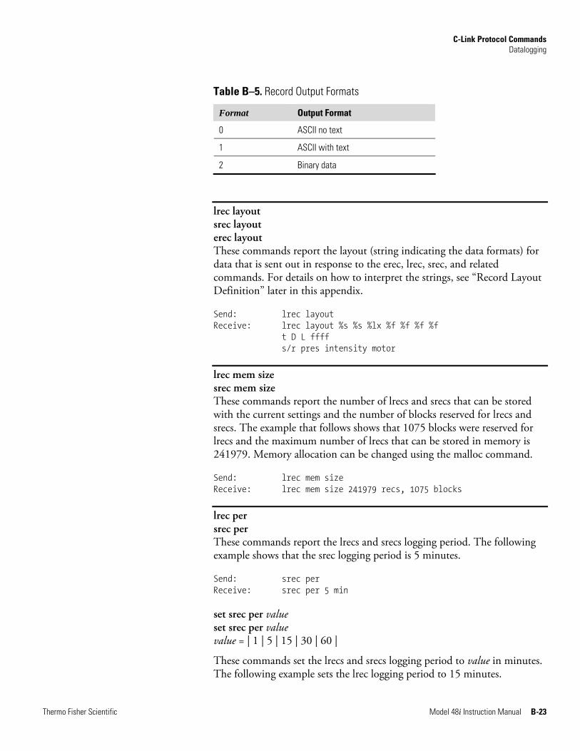
C-Link Protocol Commands Datalogging
Thermo Fisher Scientific Model 48i Instruction Manual B-23
Table B–5. Record Output Formats
Format Output Format
0 ASCII no text
1 ASCII with text
2 Binary data
lrec layout srec layout erec layout These commands report the layout (string indicating the data formats) for data that is sent out in response to the erec, lrec, srec, and related commands. For details on how to interpret the strings, see “Record Layout Definition” later in this appendix.
Send: lrec layout Receive: lrec layout %s %s %lx %f %f %f %f t D L ffff s/r pres intensity motor
lrec mem size srec mem size These commands report the number of lrecs and srecs that can be stored with the current settings and the number of blocks reserved for lrecs and srecs. The example that follows shows that 1075 blocks were reserved for lrecs and the maximum number of lrecs that can be stored in memory is 241979. Memory allocation can be changed using the malloc command.
Send: lrec mem size Receive: lrec mem size 241979 recs, 1075 blocks
lrec per srec per These commands report the lrecs and srecs logging period. The following example shows that the srec logging period is 5 minutes.
Send: srec per Receive: srec per 5 min set srec per value set srec per value value = | 1 | 5 | 15 | 30 | 60 |
These commands set the lrecs and srecs logging period to value in minutes. The following example sets the lrec logging period to 15 minutes.
C-Link Protocol Commands Datalogging
B-24 Model 48i Instruction Manual Thermo Fisher Scientific
Send: set lrec per 15 Receive: set lrec per 15 ok
no of lrec no of srec These commands report the number of lrecs and srecs stored memory. The following example shows that 50 lrecs have been stored in the memory.
Send: no of lrec Receive: no of lrec 50 recs
malloc lrec malloc srec These commands report the currently set memory allocation for lrecs and srecs in percent of total memory.
Send: malloc lrec Receive: malloc lrec 10 % set malloc lrec value set malloc srec value value = 0 to 100
These commands set the percent of memory space allocated for lrecs and srecs to value, where value is a floating-point number representing percent. The following example sets the memory allocation for lrecs to 10%.
Note Issuing these commands will clear all the logged data in memory. All the existing records should be retrieved using appropriate commands, if required. ▲
Send: set malloc lrec 10 Receive: set malloc lrec 10 ok
set copy sp to lrec set copy sp to srec set copy sp to stream These commands copy the current selections in scratch pad (sp) into the lrec, srec, or streaming data list.
The scratch pad is a temporary memory area which is used to set up lists of selections for lrec, srec, or streaming data items. The user can copy any of these lists to the scratch pad, modify individual elements in the list, then save the scratch pad back to the original list. For more information on how to edit the scratch pad, see the “sp field” command.
The following example copies the current list in scratch pad into the lrecs list.
C-Link Protocol Commands Datalogging
Thermo Fisher Scientific Model 48i Instruction Manual B-25
Send: set copy sp to lrec Receive: set copy sp to lrec ok
set copy lrec to sp set copy srec to sp set copy stream to sp These commands copy the current contents of the lrec, srec, or streaming data list into the scratch pad (sp). These commands are useful in easy modification of current lrec, srec, or streaming data lists.
The scratch pad is a temporary memory area which is used to set up lists of selections for lrec, srec, or streaming data items. The user can copy any of these lists to the scratch pad, modify individual elements in the list, then save the scratch pad back to the original list. For more information on how to edit the scratch pad, see the “sp field” command.
The following example copies the current list of lrecs into the scratch pad.
Send: set copy lrec to sp Receive: set copy lrec to sp ok
sp field number This command reports the variable number and name stored at the index in the scratch pad list.
The scratch pad is a temporary memory area which is used to set up lists of selections for lrec, srec, or streaming data items. The user can copy any of these lists to the scratch pad, modify individual elements in the list, then save the scratch pad back to the original list.
The following example shows that field 5 in the scratch pad is set to index number 8, which is for internal temperature.
Send: sp field 5 Receive: sp field 5 8 int temp set sp field number value number = 1-32 for lrec and srec lists, 1-8 for streaming data lists
This command sets the scratch pad field number (item number in scratch pad list) to value, where value is the index number of a variable in the analog output variable list. Available variables and their corresponding index numbers may be obtained using the command “list var aout”. The “set sp field” command is used to create a list of variables which can then be transferred into the lrec, srec, or streaming data lists, using the “set copy sp to lrec”, “set copy sp to srec”, or “set copy sp to stream” commands.
Send: set sp field 1 5 Receive: set sp field 1 5 ok
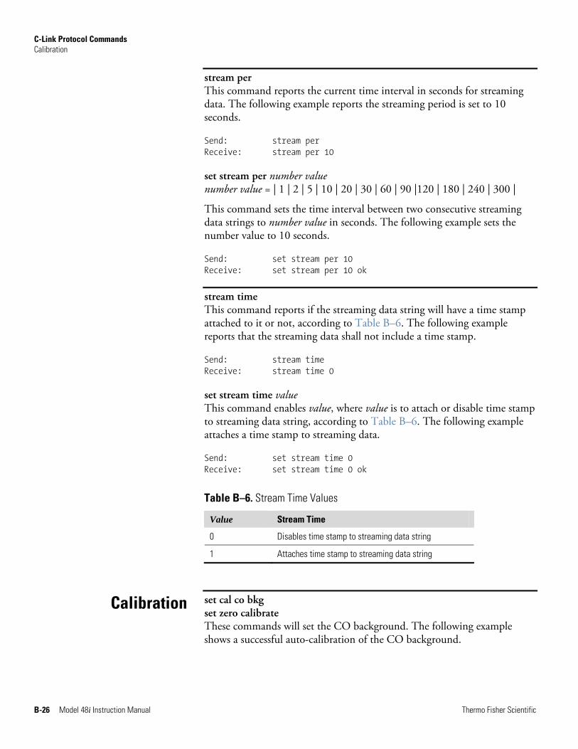
C-Link Protocol Commands Calibration
B-26 Model 48i Instruction Manual Thermo Fisher Scientific
stream per This command reports the current time interval in seconds for streaming data. The following example reports the streaming period is set to 10 seconds.
Send: stream per Receive: stream per 10 set stream per number value number value = | 1 | 2 | 5 | 10 | 20 | 30 | 60 | 90 |120 | 180 | 240 | 300 |
This command sets the time interval between two consecutive streaming data strings to number value in seconds. The following example sets the number value to 10 seconds.
Send: set stream per 10 Receive: set stream per 10 ok
stream time This command reports if the streaming data string will have a time stamp attached to it or not, according to Table B–6. The following example reports that the streaming data shall not include a time stamp.
Send: stream time Receive: stream time 0 set stream time value This command enables value, where value is to attach or disable time stamp to streaming data string, according to Table B–6. The following example attaches a time stamp to streaming data.
Send: set stream time 0 Receive: set stream time 0 ok
Table B–6. Stream Time Values
Value Stream Time
0 Disables time stamp to streaming data string
1 Attaches time stamp to streaming data string
set cal co bkg set zero calibrate These commands will set the CO background. The following example shows a successful auto-calibration of the CO background.
Calibration
C-Link Protocol Commands Calibration
Thermo Fisher Scientific Model 48i Instruction Manual B-27
Note Zero air must be provided to the instrument prior to issuing any of these commands. ▲
Send: set cal co bkg Receive: set cal co bkg ok
cal bkg o2 This command will set O2 background so the O2 concentration reads 0.00%. The example below shows a successful auto-calibration of the O2 background.
Send: set cal bkg o2 Receive: set cal bkg o2 ok
set cal co coef set cal high co coef set cal low co coef set span calibrate set calibrate These commands will set CO coefficients based on CO span gas concentrations. The high and low commands are only available in dual and auto range mode. If the mode is incorrect, the instrument responds with “can’t, wrong settings”. The following example shows a successful auto-calibration of the low CO coefficient.
Note Span gas must be provided to the instrument prior to issuing any of these commands. ▲
Send: set cal low CO coef Receive: set cal low CO coef ok
cal coef o2 This command will set O2 coefficient based on O2 span gas concentrations. The example below shows a successful auto-calibration of the O2 coefficient.
Send: set cal coef o2 Receive: set cal coef o2 ok
co coef high co coef low co coef These commands report the current CO coefficient in single range mode, or the high and low range coefficient in dual or auto range mode. If the mode is incorrect, the instrument responds with “can’t, wrong settings”. The following example reports that the CO coefficient is 1.200.
C-Link Protocol Commands Calibration
B-28 Model 48i Instruction Manual Thermo Fisher Scientific
Send: CO coef Receive: CO coef 1.200 set co coef value set high co coef value set low co coef value These commands set the CO coefficients to a user-defined value, where value is a floating-point representation of the coefficient. The following example sets the CO coefficient to 1.200.
Send: set CO coef 1.200 Receive: set CO coef 1.200 ok
coef o2 This command reports the O2 coefficient. The example below reports that the O2 coefficient is 1.000.
Send: coef o2 Receive: coef o2 1.000 set coef o2 value This command sets the O2 coefficient to a user-defined value, where value is a floating-point representation of the coefficient. The example below sets the O2 coefficient to 1.005.
Send: set coef o2 1.005 Receive: set coef o2 1.005 ok
coef 0 coef 1 coef 2 high coef 0 high coef 1 high coef 2 low coef 0 low coef 1 low coef 2 The “coef 0”, coef 1”, and coef 2” commands report the coefficients of the curve developed from the Hi Multi-Point Calibration in single range mode. The “high coef 0”, high coef 1”, and high coef 2” commands report the coefficients of the curve developed from the Hi Multi-Point Calibration in dual or auto range mode. The “low coef 0”, low coef 1”, and low coef 2” commands report the coefficients of the curve developed from the Lo Multi-Point Calibration in dual and auto range mode. The following example reports the coefficient 0 having a value of 1.005.
Send: coef 0 Receive: coef 0 1.005 ok
C-Link Protocol Commands Calibration
Thermo Fisher Scientific Model 48i Instruction Manual B-29
co bkg This command reports the current CO backgrounds. The following example reports that the CO background is 1.4 ppm.
Send: co bkg Receive: co bkg 1.4 ppm set co bkg value This command is used to set the CO background to a user-defined value, where value is a floating-point representation of the background in the currently selected units. The following example sets the CO background to 1.4 ppm.
Send: set co bkg 1.400 Receive: set co bkg 1.400 ok
bkg o2 This command reports the oxygen background concentration in percent. The following example reports that the current O2 background concentration is 1.5%.
Send: bkg o2 Receive: bkg o2 1.50 % set bkg o2 This command is used to set the oxygen background concentration in percent. The example below sets the O2 background concentration to 1.5%.
Send: set bkg o2 1.5 Receive: set bkg o2 1.5 ok
init ratio This command reports the initial sample/reference ratio. The following example reports that the initial ratio was 1.16210.
Send: initial ratio Receive: initial ratio 1.16210
sp conc high sp conc low sp conc These commands report span concentration in single range mode, or the high and low span concentrations in dual or auto range mode. If the mode is incorrect, the instrument responds with “can’t, wrong settings”. The following example reports the span gas concentration in single range mode.
C-Link Protocol Commands Calibration
B-30 Model 48i Instruction Manual Thermo Fisher Scientific
Send: sp conc Receive: sp conc 1000 set sp conc value set high sp conc value set low sp conc value These commands set the span concentration to a user-defined value, where value is a floating-point representation of the span concentration in the currently selected units. The following example sets the span concentration to 1000 ppm in the single range mode.
Send: set sp conc 1000 Receive: set sp conc 1000 ok
o2 gas This command reports the O2 span gas concentrations used to auto-calibrate O2 coefficients. The example below reports that the O2 span gas concentration is 20.8%.
Send: o2 gas Receive: o2 gas 20.8 % set o2 gas value This command sets the O2 span gas concentration used by the auto-calibration routine to value, where value is a floating-point representation of the gas concentration in percent. The gas units are the same as those chosen by the user. The example below sets the O2 span gas concentration to 20.8 %.
Send: set o2 gas 20.8 Receive: set o2 gas 20.8 ok
span cal reset This command reports that the span cal reset is on or off. The following example reports that the span cal reset is on.
Send: span cal reset Receive: span cal reset on
set span cal reset onoff onoff = | on | off |
This command sets the span cal reset to on or off. The following example sets the span cal reset to off.
Send: set span cal reset off Receive: set span cal reset off ok
C-Link Protocol Commands Calibration
Thermo Fisher Scientific Model 48i Instruction Manual B-31
span dev This command reports the span deviation (span check offset). The following example reports that the span deviation is 1 ppb.
Send: span dev Receive: span dev 1.000 E+00
set span dev value This command sets the span deviation (span check offset) to value, where value is a floating-point representation of the gas concentration in current selected units. The following example sets the span deviation to 345 ppb.
Send: set span dev 345 Receive: set span dev 345 ok
span dur This command reports the span duration. The following example reports that the span duration min is 10 minutes.
Send: span dur Receive: span dur 10 min
set span dur value This command sets span duration to value where value represents the span duration in minutes. The following example sets the span duration to 15 minutes.
Send: set span dur 15 Receive: set span dur 15 ok
zero cal reset This command reports that the zero cal reset is on or off. The following example reports that the zero cal reset is off.
Send: zero cal reset Receive: zero cal reset off
set zero cal reset onoff onoff = | on | off |
This command sets the zero cal reset on or off. The following example turns the zero cal reset off.
Send: set zero cal reset off Receive: set zero cal reset off ok
C-Link Protocol Commands Calibration
B-32 Model 48i Instruction Manual Thermo Fisher Scientific
zero dev This command reports the zero deviation (maximum zero check offset). The following example reports that the zero deviation is 10 ppb.
Send: zero dev Receive: zero dev 1.000 E+01
set zero dev value This command sets the zero deviation (maximum zero check offset) to value, where value is a floating-point representation of the gas concentration in current selected units. The following example sets the zero deviation to 10 ppb.
Send: set zero dev 1.000 E+01 Receive: set zero dev 1.000 E+01 ok
zero dur This command reports the zero duration. The following example reports that the zero duration is 10 minutes.
Send: zero dur 10 Receive: zero dur 10 ok
set zero dur value This command sets the zero duration to value where value represents the zero duration in minutes. The following example sets the zero duration to 15 minutes.
Send: set zero dur 15 Receive: set zero dur 15 ok
zs period This command reports the zero/span (zs) period. The following example reports that the zero/span period is 24 hours.
Send: zs period Receive: zs period 24 hr
set zs period value This command sets zero/span (zs) period to value, where value represents the zero/span period in hours. The following example sets the zero/span period to 24 hours.
Send: set zs period 24 Receive: set zs period 24 ok
C-Link Protocol Commands Keys/Display
Thermo Fisher Scientific Model 48i Instruction Manual B-33
zs avg time This command reports the zero/span (zs) averaging time in seconds. The following example reports that the zero/span averaging time is 30 seconds, according to Table B–3.
Send: zs avg time Receive: zs avg time 5:30 sec
set avg time value This command sets the zero/span averaging time, according to Table B–3. The following example sets the zero/span averaging time to 120 seconds.
Send: set zs avg time 8 Receive: set zs avg time 8 ok
push button do ri down right en ru enter run he up help 1 le 2 left 3 me 4 menu button = | do | down | en | enter | he | help | le | left | me | menu | ri | right | ru | run | up | 1 | 2 | 3 | 4 |
These commands simulate pressing the front panel pushbuttons. The numbers represent the front panel soft keys, from left to right.
Send: push enter Receive: push enter ok
isc iscreen These commands retrieve the framebuffer data used for the display on the iSeries instrument. It is 19200 bytes in size, 2-bits per pixel, 4 pixels per byte arranged as 320 by 240 characters. The data is sent in RLE encoded form to save time in transmission. It is sent as a type '5' binary C-Link response with no checksum.
The RLE encoding consists of a 0 followed by an 8-bit count of consecutive 0xFF bytes. The following 'c' code will expand the incoming data.
Keys/Display
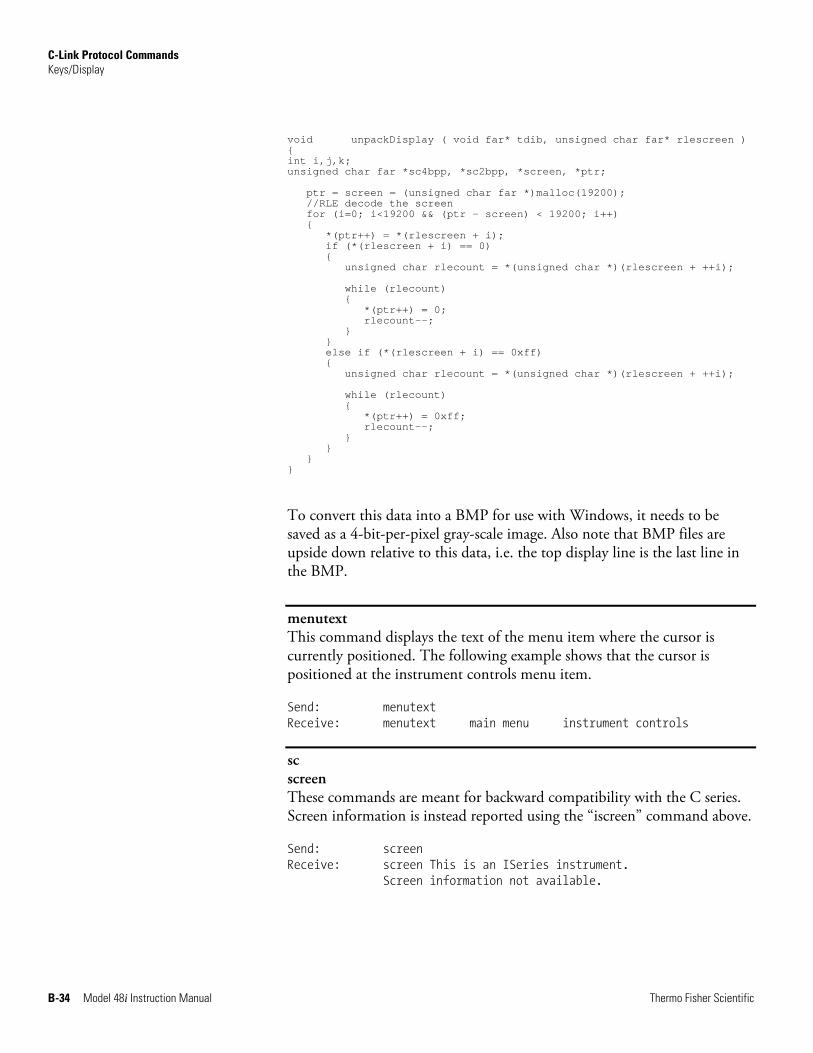
C-Link Protocol Commands Keys/Display
B-34 Model 48i Instruction Manual Thermo Fisher Scientific
void unpackDisplay ( void far* tdib, unsigned char far* rlescreen ) { int i,j,k; unsigned char far *sc4bpp, *sc2bpp, *screen, *ptr;
ptr = screen = (unsigned char far *)malloc(19200); //RLE decode the screen for (i=0; i<19200 && (ptr - screen) < 19200; i++) { *(ptr++) = *(rlescreen + i); if (*(rlescreen + i) == 0) { unsigned char rlecount = *(unsigned char *)(rlescreen + ++i); while (rlecount) { *(ptr++) = 0; rlecount--; } } else if (*(rlescreen + i) == 0xff) { unsigned char rlecount = *(unsigned char *)(rlescreen + ++i); while (rlecount) { *(ptr++) = 0xff; rlecount--; } } } }
To convert this data into a BMP for use with Windows, it needs to be saved as a 4-bit-per-pixel gray-scale image. Also note that BMP files are upside down relative to this data, i.e. the top display line is the last line in the BMP.
menutext This command displays the text of the menu item where the cursor is currently positioned. The following example shows that the cursor is positioned at the instrument controls menu item.
Send: menutext Receive: menutext main menu instrument controls
sc screen These commands are meant for backward compatibility with the C series. Screen information is instead reported using the “iscreen” command above.
Send: screen Receive: screen This is an ISeries instrument.
Screen information not available.
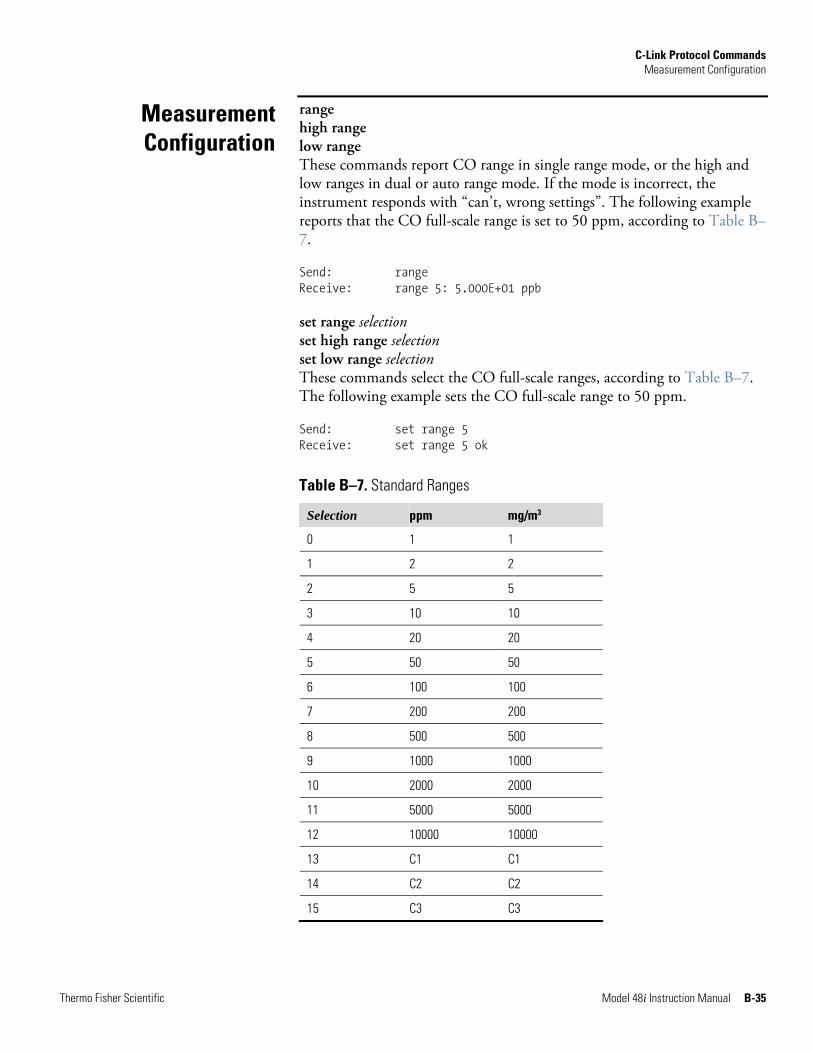
C-Link Protocol Commands Measurement Configuration
Thermo Fisher Scientific Model 48i Instruction Manual B-35
range high range low range These commands report CO range in single range mode, or the high and low ranges in dual or auto range mode. If the mode is incorrect, the instrument responds with “can’t, wrong settings”. The following example reports that the CO full-scale range is set to 50 ppm, according to Table B–7.
Send: range Receive: range 5: 5.000E+01 ppb set range selection set high range selection set low range selection These commands select the CO full-scale ranges, according to Table B–7. The following example sets the CO full-scale range to 50 ppm.
Send: set range 5 Receive: set range 5 ok
Table B–7. Standard Ranges
Selection ppm mg/m3
0 1 1
1 2 2
2 5 5
3 10 10
4 20 20
5 50 50
6 100 100
7 200 200
8 500 500
9 1000 1000
10 2000 2000
11 5000 5000
12 10000 10000
13 C1 C1
14 C2 C2
15 C3 C3
Measurement Configuration
C-Link Protocol Commands Measurement Configuration
B-36 Model 48i Instruction Manual Thermo Fisher Scientific
custom range range = | 1 | 2 | 3 |
This command reports the user-defined value of custom range 1, 2, or 3. The following example reports that custom range 1 is defined to 5.50 ppm.
Send: custom 1 Receive: custom 1 5.500E+3 ppm set custom range range value set custom 1 range value set custom 2 range value set custom 3 range value These commands are used to set the maximum concentration for any of the three custom ranges 1, 2, or 3 to range value, where value is a floating-point number representing concentration in ppm or mg/m3. The following example sets the custom 1 range to 55.5 ppm.
Send: set custom 1 range 55.5 Receive: set custom 1 range 55.5 ok
range mode This command reports the current range mode.
Send: range mode Receive: range mode single set range mode mode
This command sets the current range mode to single, dual, or auto. The following example sets the range mode to single.
Send: set range mode single Receive: set range mode single ok
gas mode This command reports the current state of the zero/span valves gas mode as sample, zero, or span. The following example reports that the gas mode is sample.
Send: gas mode Receive: gas mode sample
set sample This command sets the zero/span valves to the sample mode. The following example sets the instrument to sample mode, that is, the instrument is reading the sample gas.
C-Link Protocol Commands Measurement Configuration
Thermo Fisher Scientific Model 48i Instruction Manual B-37
Send: set sample Receive: set sample ok
set zero This command sets the zero/span valves to the zero mode. The following example sets the instrument to zero mode that is, the instrument is reading the zero gas.
Send: set zero Receive: set zero ok
set span This command sets the zero/span valves to the span mode. The following example sets the instrument to span mode that is, the instrument is reading span gas.
Send: set span Receive: set span ok
gas unit This command reports the current gas units (ppm or mg/m3). The example reports that the gas unit is set to ppm.
Send: gas unit Receive: gas unit ppm set gas unit unit unit = | ppm | mg/m3 |
This command sets the gas units to ppm or mg/m3. The following example sets the gas units to mg/m3.
Send: set gas unit mg/m3 Receive: set gas unit mg/m3 ok
pres comp This command reports whether pressure compensation is on or off. The following example shows that pressure compensation is on.
Send: pres comp Receive: pres comp on set pres comp onoff onoff = | on | off |
These commands turn the pressure compensation on or off. The following example turns pressure compensation off.
Send: set pres comp off Receive: set pres comp off ok
C-Link Protocol Commands Hardware Configuration
B-38 Model 48i Instruction Manual Thermo Fisher Scientific
temp comp This command reports whether temperature compensation is on or off. The following example shows the temperature compensation is off.
Send: temp comp Receive: temp comp off set temp comp onoff onoff = | on | off |
These commands turn the temperature compensation on or off. The following example turns temperature compensation off.
Send: set temp comp off Receive: set temp comp off ok
oc o2 corr These command report whether oxygen correction (compensation) is on or off. The following example reports that the O2 correction is on.
Send: o2 corr Receive: o2 corr on set oc onoff set o2 corr onoff onoff = | on | off |
These commands turn the oxygen correction (compensation) on or off. The following example turns the O2 correction off.
Send: set oc off Receive: set oc off ok
contrast This command reports the screen’s level of contrast. The following example shows the screen contrast is 50%, according to Table B–8.
Send: contrast Receive: contrast 10:50% set contrast level This command sets the screen’s level of contrast, according to Table B–8. The following example sets the contrast level to 50%.
Send: set contrast 10 Receive: set contrast 10 ok
Hardware Configuration
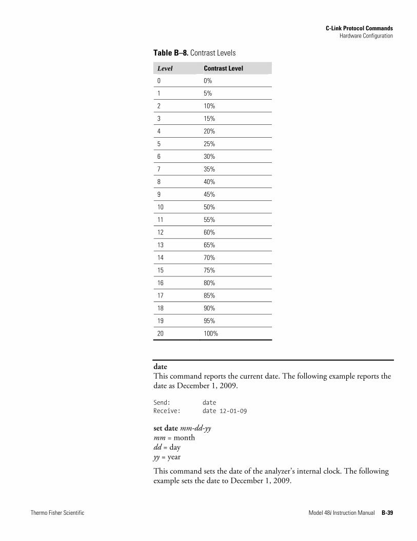
C-Link Protocol Commands Hardware Configuration
Thermo Fisher Scientific Model 48i Instruction Manual B-39
Table B–8. Contrast Levels
Level Contrast Level
0 0%
1 5%
2 10%
3 15%
4 20%
5 25%
6 30%
7 35%
8 40%
9 45%
10 50%
11 55%
12 60%
13 65%
14 70%
15 75%
16 80%
17 85%
18 90%
19 95%
20 100%
date This command reports the current date. The following example reports the date as December 1, 2009.
Send: date Receive: date 12-01-09 set date mm-dd-yy mm = month dd = day yy = year
This command sets the date of the analyzer’s internal clock. The following example sets the date to December 1, 2009.
C-Link Protocol Commands Communications Configuration
B-40 Model 48i Instruction Manual Thermo Fisher Scientific
Send: set date 12-01-09 Receive: set date 12-01-09 ok
set default params This command sets all the parameters to their default values. This does not affect the factory-calibrated parameters.
Send: set default params Receive: set default params ok
save set save params This command stores all current parameters in FLASH memory. It is important that each time instrument parameters are changed, that this command be sent. If changes are not saved, they will be lost in the event of a power failure. The following example saves the parameters to FLASH memory.
Send: set save params Receive: set save params ok
time This command reports the current time (24-hour time). The following example reports that the internal time is 2:15:30 pm.
Send: time Receive: time 14:15:30 set time hh:mm:ss hh = hours mm = minutes ss = seconds
This command sets the internal clock (24-hour time). The following example sets the internal time to 2:15 pm.
Note If seconds are omitted, the seconds default to 00. ▲
Send: set time 14:15 Receive: set time 14:15 ok
addr dns This command reports the TCP/IP address for the domain name server.
Send: addr dns Receive: addr dns 192.168.1.1
Communications Configuration
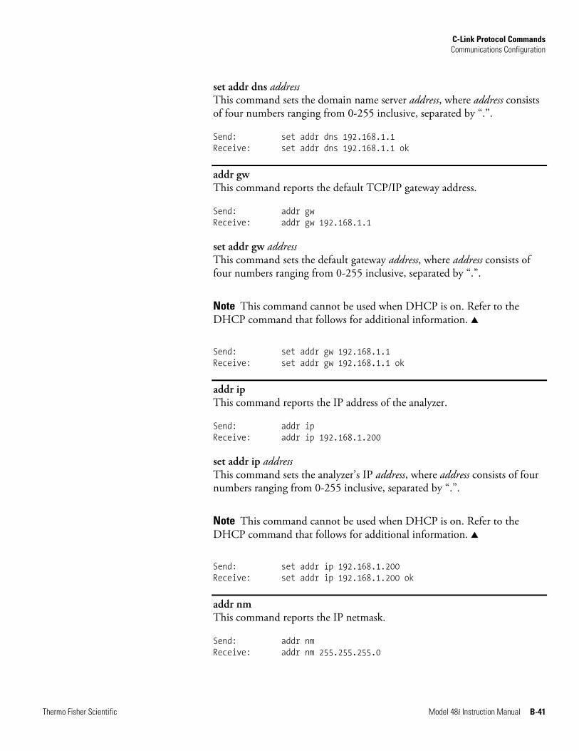
C-Link Protocol Commands Communications Configuration
Thermo Fisher Scientific Model 48i Instruction Manual B-41
set addr dns address This command sets the domain name server address, where address consists of four numbers ranging from 0-255 inclusive, separated by “.”.
Send: set addr dns 192.168.1.1 Receive: set addr dns 192.168.1.1 ok
addr gw This command reports the default TCP/IP gateway address.
Send: addr gw Receive: addr gw 192.168.1.1 set addr gw address This command sets the default gateway address, where address consists of four numbers ranging from 0-255 inclusive, separated by “.”.
Note This command cannot be used when DHCP is on. Refer to the DHCP command that follows for additional information. ▲
Send: set addr gw 192.168.1.1 Receive: set addr gw 192.168.1.1 ok
addr ip This command reports the IP address of the analyzer.
Send: addr ip Receive: addr ip 192.168.1.200 set addr ip address This command sets the analyzer’s IP address, where address consists of four numbers ranging from 0-255 inclusive, separated by “.”.
Note This command cannot be used when DHCP is on. Refer to the DHCP command that follows for additional information. ▲
Send: set addr ip 192.168.1.200 Receive: set addr ip 192.168.1.200 ok
addr nm This command reports the IP netmask.
Send: addr nm Receive: addr nm 255.255.255.0
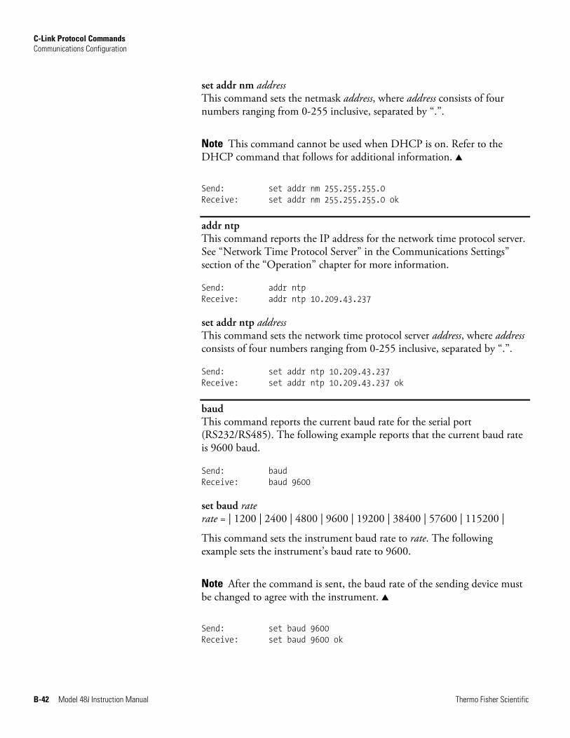
C-Link Protocol Commands Communications Configuration
B-42 Model 48i Instruction Manual Thermo Fisher Scientific
set addr nm address This command sets the netmask address, where address consists of four numbers ranging from 0-255 inclusive, separated by “.”.
Note This command cannot be used when DHCP is on. Refer to the DHCP command that follows for additional information. ▲
Send: set addr nm 255.255.255.0 Receive: set addr nm 255.255.255.0 ok
addr ntp This command reports the IP address for the network time protocol server. See “Network Time Protocol Server” in the Communications Settings” section of the “Operation” chapter for more information.
Send: addr ntp Receive: addr ntp 10.209.43.237 set addr ntp address This command sets the network time protocol server address, where address consists of four numbers ranging from 0-255 inclusive, separated by “.”.
Send: set addr ntp 10.209.43.237 Receive: set addr ntp 10.209.43.237 ok
baud This command reports the current baud rate for the serial port (RS232/RS485). The following example reports that the current baud rate is 9600 baud.
Send: baud Receive: baud 9600 set baud rate rate = | 1200 | 2400 | 4800 | 9600 | 19200 | 38400 | 57600 | 115200 |
This command sets the instrument baud rate to rate. The following example sets the instrument’s baud rate to 9600.
Note After the command is sent, the baud rate of the sending device must be changed to agree with the instrument. ▲
Send: set baud 9600 Receive: set baud 9600 ok
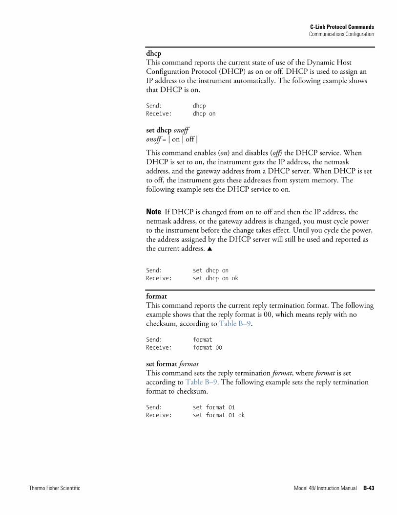
C-Link Protocol Commands Communications Configuration
Thermo Fisher Scientific Model 48i Instruction Manual B-43
dhcp This command reports the current state of use of the Dynamic Host Configuration Protocol (DHCP) as on or off. DHCP is used to assign an IP address to the instrument automatically. The following example shows that DHCP is on.
Send: dhcp Receive: dhcp on set dhcp onoff onoff = | on | off |
This command enables (on) and disables (off) the DHCP service. When DHCP is set to on, the instrument gets the IP address, the netmask address, and the gateway address from a DHCP server. When DHCP is set to off, the instrument gets these addresses from system memory. The following example sets the DHCP service to on.
Note If DHCP is changed from on to off and then the IP address, the netmask address, or the gateway address is changed, you must cycle power to the instrument before the change takes effect. Until you cycle the power, the address assigned by the DHCP server will still be used and reported as the current address. ▲
Send: set dhcp on Receive: set dhcp on ok
format This command reports the current reply termination format. The following example shows that the reply format is 00, which means reply with no checksum, according to Table B–9.
Send: format Receive: format 00 set format format This command sets the reply termination format, where format is set according to Table B–9. The following example sets the reply termination format to checksum.
Send: set format 01 Receive: set format 01 ok
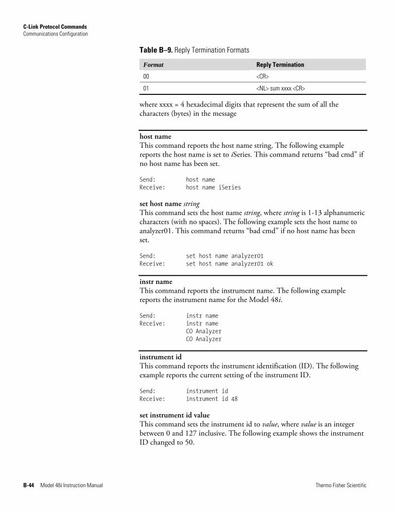
C-Link Protocol Commands Communications Configuration
B-44 Model 48i Instruction Manual Thermo Fisher Scientific
Table B–9. Reply Termination Formats
Format Reply Termination
00 <CR>
01 <NL> sum xxxx <CR>
where xxxx = 4 hexadecimal digits that represent the sum of all the characters (bytes) in the message
host name This command reports the host name string. The following example reports the host name is set to iSeries. This command returns “bad cmd” if no host name has been set.
Send: host name Receive: host name iSeries set host name string This command sets the host name string, where string is 1-13 alphanumeric characters (with no spaces). The following example sets the host name to analyzer01. This command returns “bad cmd” if no host name has been set.
Send: set host name analyzer01 Receive: set host name analyzer01 ok
instr name This command reports the instrument name. The following example reports the instrument name for the Model 48i.
Send: instr name Receive: instr name CO Analyzer CO Analyzer
instrument id This command reports the instrument identification (ID). The following example reports the current setting of the instrument ID.
Send: instrument id Receive: instrument id 48 set instrument id value This command sets the instrument id to value, where value is an integer between 0 and 127 inclusive. The following example shows the instrument ID changed to 50.
C-Link Protocol Commands Communications Configuration
Thermo Fisher Scientific Model 48i Instruction Manual B-45
Note Note sending this command via RS-232 or RS-485 will require the host to use the new id for subsequent commands. ▲
Send: set instrument id 50 Receive: set instrument id 50 ok
mode This command reports what operating mode the instrument is in: local, service, or remote. The following example shows that the instrument is in the remote mode.
Send: mode Receive: mode remote set mode local set mode remote These commands set the instrument to local or remote mode. The following example sets the instrument to the local mode.
Send: set mode local Receive: set mode local ok
allow mode cmd This command reports the current allow mode setting: 1 = allow “set mode local” and “set mode remote” commands; 0 = ignore “set mode local” or “set mode remote”commands, according to Table B–10. The default value is 0; ignore the commands. The following example shows that the instrument is configured to ignore “set mode local” or “set mode remote” commands.
Send: allow mode cmd Receive: allow mode cmd 0 set allow mode cmd value This command is used to configure the instrument to value, where value is either 1 = accept or 0 = ignore the “set mode local” and “set mode remote” commands, according to Table B–10.
If the instrument is set to accept the commands (value = 1), the “set mode local” command will unlock the instrument and the keypad can be used to make changes via the front panel.
If the instrument is set to ignore the commands (value = 0), the instrument will respond with “ok” as if the command has been accepted and acted
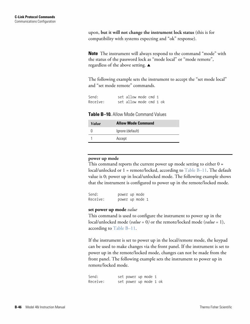
C-Link Protocol Commands Communications Configuration
B-46 Model 48i Instruction Manual Thermo Fisher Scientific
upon, but it will not change the instrument lock status (this is for compatibility with systems expecting and “ok” response).
Note The instrument will always respond to the command “mode” with the status of the password lock as “mode local” or “mode remote”, regardless of the above setting. ▲
The following example sets the instrument to accept the “set mode local” and “set mode remote” commands.
Send: set allow mode cmd 1 Receive: set allow mode cmd 1 ok
Table B–10. Allow Mode Command Values
Value Allow Mode Command
0 Ignore (default)
1 Accept
power up mode This command reports the current power up mode setting to either 0 = local/unlocked or 1 = remote/locked, according to Table B–11. The default value is 0; power up in local/unlocked mode. The following example shows that the instrument is configured to power up in the remote/locked mode. Send: power up mode Receive: power up mode 1 set power up mode value This command is used to configure the instrument to power up in the local/unlocked mode (value = 0) or the remote/locked mode (value = 1), according to Table B–11.
If the instrument is set to power up in the local/remote mode, the keypad can be used to make changes via the front panel. If the instrument is set to power up in the remote/locked mode, changes can not be made from the front panel. The following example sets the instrument to power up in remote/locked mode.
Send: set power up mode 1 Receive: set power up mode 1 ok
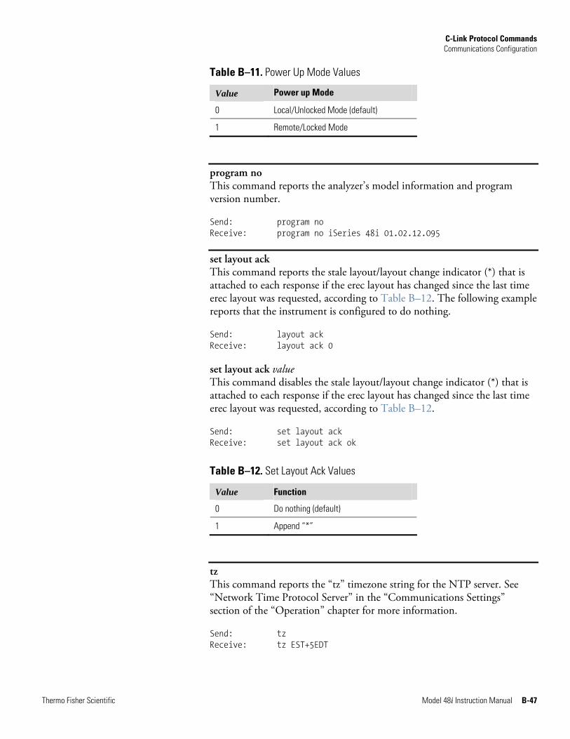
C-Link Protocol Commands Communications Configuration
Thermo Fisher Scientific Model 48i Instruction Manual B-47
Table B–11. Power Up Mode Values
Value Power up Mode
0 Local/Unlocked Mode (default)
1 Remote/Locked Mode
program no This command reports the analyzer’s model information and program version number.
Send: program no Receive: program no iSeries 48i 01.02.12.095
set layout ack This command reports the stale layout/layout change indicator (*) that is attached to each response if the erec layout has changed since the last time erec layout was requested, according to Table B–12. The following example reports that the instrument is configured to do nothing.
Send: layout ack Receive: layout ack 0 set layout ack value This command disables the stale layout/layout change indicator (*) that is attached to each response if the erec layout has changed since the last time erec layout was requested, according to Table B–12.
Send: set layout ack Receive: set layout ack ok
Table B–12. Set Layout Ack Values
Value Function
0 Do nothing (default)
1 Append “*”
tz This command reports the “tz” timezone string for the NTP server. See “Network Time Protocol Server” in the “Communications Settings” section of the “Operation” chapter for more information.
Send: tz Receive: tz EST+5EDT
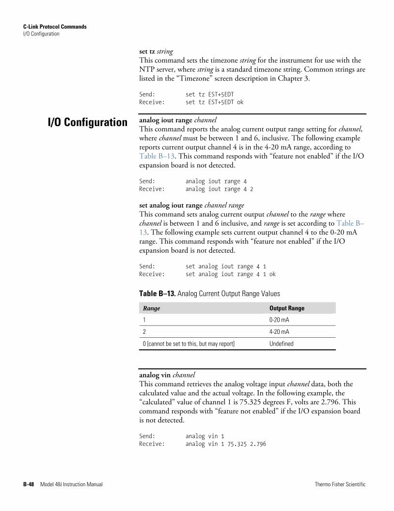
C-Link Protocol Commands I/O Configuration
B-48 Model 48i Instruction Manual Thermo Fisher Scientific
set tz string This command sets the timezone string for the instrument for use with the NTP server, where string is a standard timezone string. Common strings are listed in the “Timezone” screen description in Chapter 3.
Send: set tz EST+5EDT Receive: set tz EST+5EDT ok
analog iout range channel This command reports the analog current output range setting for channel, where channel must be between 1 and 6, inclusive. The following example reports current output channel 4 is in the 4-20 mA range, according to Table B–13. This command responds with “feature not enabled” if the I/O expansion board is not detected.
Send: analog iout range 4 Receive: analog iout range 4 2 set analog iout range channel range This command sets analog current output channel to the range where channel is between 1 and 6 inclusive, and range is set according to Table B–13. The following example sets current output channel 4 to the 0-20 mA range. This command responds with “feature not enabled” if the I/O expansion board is not detected.
Send: set analog iout range 4 1 Receive: set analog iout range 4 1 ok
Table B–13. Analog Current Output Range Values
Range Output Range
1 0-20 mA
2 4-20 mA
0 [cannot be set to this, but may report] Undefined
analog vin channel This command retrieves the analog voltage input channel data, both the calculated value and the actual voltage. In the following example, the “calculated” value of channel 1 is 75.325 degrees F, volts are 2.796. This command responds with “feature not enabled” if the I/O expansion board is not detected.
Send: analog vin 1 Receive: analog vin 1 75.325 2.796
I/O Configuration
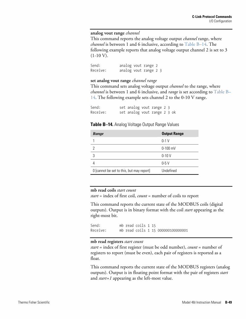
C-Link Protocol Commands I/O Configuration
Thermo Fisher Scientific Model 48i Instruction Manual B-49
analog vout range channel This command reports the analog voltage output channel range, where channel is between 1 and 6 inclusive, according to Table B–14. The following example reports that analog voltage output channel 2 is set to 3 (1-10 V).
Send: analog vout range 2 Receive: analog vout range 2 3 set analog vout range channel range This command sets analog voltage output channel to the range, where channel is between 1 and 6 inclusive, and range is set according to Table B–14. The following example sets channel 2 to the 0-10 V range.
Send: set analog vout range 2 3 Receive: set analog vout range 2 3 ok
Table B–14. Analog Voltage Output Range Values
Range Output Range
1 0-1 V
2 0-100 mV
3 0-10 V
4 0-5 V
0 [cannot be set to this, but may report] Undefined
mb read coils start count start = index of first coil, count = number of coils to report
This command reports the current state of the MODBUS coils (digital outputs). Output is in binary format with the coil start appearing as the right-most bit.
Send: mb read coils 1 15 Receive: mb read coils 1 15 000000100000001
mb read registers start count start = index of first register (must be odd number), count = number of registers to report (must be even), each pair of registers is reported as a float.
This command reports the current state of the MODBUS registers (analog outputs). Output is in floating point format with the pair of registers start and start+1 appearing as the left-most value.
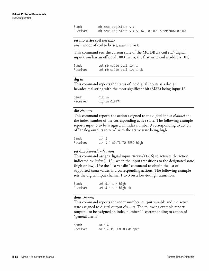
C-Link Protocol Commands I/O Configuration
B-50 Model 48i Instruction Manual Thermo Fisher Scientific
Send: mb read registers 5 4 Receive: mb read registers 5 4 552629 000000 55998800.000000
set mb write coil coil state coil = index of coil to be set, state = 1 or 0
This command sets the current state of the MODBUS coil coil (digital input). coil has an offset of 100 (that is, the first write coil is address 101).
Send: set mb write coil 104 1 Receive: set mb write coil 104 1 ok
dig in This command reports the status of the digital inputs as a 4-digit hexadecimal string with the most significant bit (MSB) being input 16.
Send: dig in Receive: dig in 0xff7f
din channel This command reports the action assigned to the digital input channel and the index number of the corresponding active state. The following example reports input 5 to be assigned an index number 9 corresponding to action of “analog outputs to zero” with the active state being high.
Send: din 5 Receive: din 5 9 AOUTS TO ZERO high set din channel index state This command assigns digital input channel (1-16) to activate the action indicated by index (1-12), when the input transitions to the designated state (high or low). Use the “list var din” command to obtain the list of supported index values and corresponding actions. The following example sets the digital input channel 1 to 3 on a low-to-high transition.
Send: set din 1 3 high Receive: set din 1 3 high ok
dout channel This command reports the index number, output variable and the active state assigned to digital output channel. The following example reports output 4 to be assigned an index number 11 corresponding to action of “general alarm”.
Send: dout 4 Receive: dout 4 11 GEN ALARM open
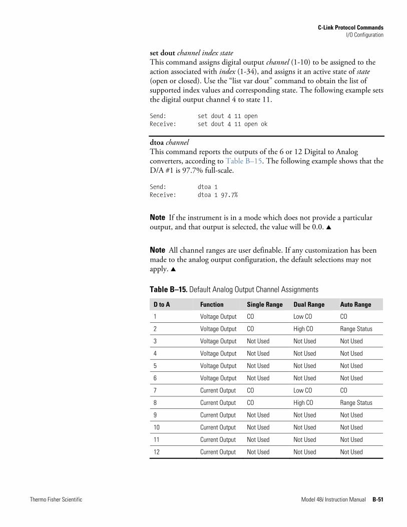
C-Link Protocol Commands I/O Configuration
Thermo Fisher Scientific Model 48i Instruction Manual B-51
set dout channel index state This command assigns digital output channel (1-10) to be assigned to the action associated with index (1-34), and assigns it an active state of state (open or closed). Use the “list var dout” command to obtain the list of supported index values and corresponding state. The following example sets the digital output channel 4 to state 11.
Send: set dout 4 11 open Receive: set dout 4 11 open ok
dtoa channel This command reports the outputs of the 6 or 12 Digital to Analog converters, according to Table B–15. The following example shows that the D/A #1 is 97.7% full-scale.
Send: dtoa 1 Receive: dtoa 1 97.7%
Note If the instrument is in a mode which does not provide a particular output, and that output is selected, the value will be 0.0. ▲
Note All channel ranges are user definable. If any customization has been made to the analog output configuration, the default selections may not apply. ▲
Table B–15. Default Analog Output Channel Assignments
D to A Function Single Range Dual Range Auto Range
1 Voltage Output CO Low CO CO
2 Voltage Output CO High CO Range Status
3 Voltage Output Not Used Not Used Not Used
4 Voltage Output Not Used Not Used Not Used
5 Voltage Output Not Used Not Used Not Used
6 Voltage Output Not Used Not Used Not Used
7 Current Output CO Low CO CO
8 Current Output CO High CO Range Status
9 Current Output Not Used Not Used Not Used
10 Current Output Not Used Not Used Not Used
11 Current Output Not Used Not Used Not Used
12 Current Output Not Used Not Used Not Used
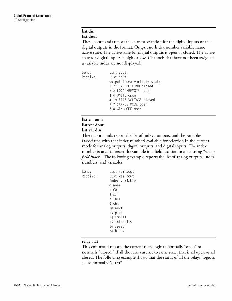
C-Link Protocol Commands I/O Configuration
B-52 Model 48i Instruction Manual Thermo Fisher Scientific
list din list dout These commands report the current selection for the digital inputs or the digital outputs in the format. Output no Index number variable name active state. The active state for digital outputs is open or closed. The active state for digital inputs is high or low. Channels that have not been assigned a variable index are not displayed.
Send: list dout Receive: list dout output index variable state 1 22 I/O BD COMM closed 2 2 LOCAL/REMOTE open 3 4 UNITS open 4 19 BIAS VOLTAGE closed 7 7 SAMPLE MODE open 8 8 GEN MODE open
list var aout list var dout list var din These commands report the list of index numbers, and the variables (associated with that index number) available for selection in the current mode for analog outputs, digital outputs, and digital inputs. The index number is used to insert the variable in a field location in a list using “set sp field index”. The following example reports the list of analog outputs, index numbers, and variables.
Send: list var aout Receive: list var aout index variable 0 none 1 CO 5 sr 8 intt 9 cht 10 auxt 13 pres 14 smplfl 15 intensity 16 speed 28 biasv
relay stat This command reports the current relay logic as normally “open” or normally “closed,” if all the relays are set to same state, that is all open or all closed. The following example shows that the status of all the relays’ logic is set to normally “open”.
C-Link Protocol Commands Record Layout Definition
Thermo Fisher Scientific Model 48i Instruction Manual B-53
Send: relay stat Receive: relay stat open
Note If individual relays have been assigned different logic, then the response would be a 4-digit hexadecimal string with the least significant byte (LSB) being relay no 1. ▲
For example:
Receive: relay stat 0x0001 (indicates relay no 1 is set to normally open logic, all others are normally closed)
Receive: relay stat 0x0005 (indicates relay no 1 and 3 are set to be normally open logic, all others are normally closed)
set relay open set relay open value set relay closed set relay closed value These commands set the relay logic to normally open or closed for relay number value, where value is the relay between 1 and 16. The following example sets the relay no 1 logic to normally open.
Note If the command is sent without an appended relay number, then all the relays are assigned the set logic of normally open/closed. ▲
Send: set relay open 1 Receive: set relay open 1 ok
The erec, lrec, and srec layouts contain the following:
● A format specifier for parsing ASCII responses
● A format specifier for parsing binary responses
In addition to these, the erec layout contains:
● A format specifier for producing the front panel display screens
Values are read using either the ASCII or binary format specifiers and converted to uniform internal representations (32-bit floats or 32-bit integers). These values are converted into text for display on the screen using the format specifier for the front panel display. Normally, the specifier used to parse a particular datum from the input stream will be strongly related to the specifier used to display it (such as, all of the floating point inputs will be displayed with an 'f' output specifier, and all of the integer inputs will be displayed with a 'd' specifier).
Record Layout Definition
C-Link Protocol Commands Record Layout Definition
B-54 Model 48i Instruction Manual Thermo Fisher Scientific
The first line of the layout response is the scanf-like parameter list for parsing the fields from an ASCII erec response. Parameters are separated by spaces and the line is terminated by a “\n” (the normal line separator character). Valid fields are:
%s - parse a string %d - parse a decimal number %ld - parse a long (32-bit) decimal number %f - parse a floating point number %x - parse a hexadecimal number %lx - parse a long (32-bit) hex number %* - ignore the field
Note Signed versus unsigned for the integer values does not matter; it is handled automatically. ▲
The second line of the layout response is the binary parameter list for parsing the fields from a binary response. Parameters MUST be separated by spaces, and the line is terminated by a '\n'. Valid fields are:
t - parse a time specifier (2 bytes) D - parse a date specifier (3 bytes) i - ignore one 8-bit character (1 byte) e - parse a 24-bit floating point number (3 bytes: n/x) E - parse a 24-bit floating point number (3 bytes: N/x) f - parse a 32-bit floating point number (4 bytes)
c - parse an 8-bit signed number (1 byte) C - parse an 8-bit unsigned number (1 byte) n - parse a 16-bit signed number (2 bytes) N - parse a 16-bit unsigned number (2 bytes) m - parse a 24-bit signed number (3 bytes) M - parse a 24-bit unsigned number (3 bytes) l - parse a 32-bit signed number (4 bytes) L - parse a 32-bit unsigned number (4 bytes)
There is an optional single digit d which may follow any of the numeric fields, which indicates that after the field has been parsed out, the resulting value is to be divided by 10^d. Thus the 16-bit field 0xFFC6 would be interpreted with the format specifier 'n3' as the number -0.058.
The subsequent lines in the erec layout response describe the appearance of the full panel. The full instrument panel as it appears on the screen has two
Format Specifier for ASCII Responses
Format Specifier for Binary Responses
Format Specifier for Erec Layout
C-Link Protocol Commands Record Layout Definition
Thermo Fisher Scientific Model 48i Instruction Manual B-55
columns of lines. Each line is composed of three major components: (1) a text field, (2) a value field, and (3) a button. None of these three components is required. The text field contains statically displayed text.
The value field displays values which are parsed out of the response to a erec command. It also displays, though background changes, alarm status. The button, when pressed, triggers input from either a dialog box or a selection list. There are five kinds of buttons, B, I, L, T, and N.
Each line in the layout string corresponds to one line on the display. The layout string describes each of the three major fields as well as translation mechanisms and corresponding commands.
The first field in the layout string is the text. It is delimited by a ':'. The string up to the first ':' will be read and inserted in the text field of the line.
This is followed by a possible string enclosed in quotes that is used to place a string into the value field.
The value source, which is the item (or word) number in the DATA/EREC response, appears next. This is followed by an optional bitfield designator. The datum identified by the value source can be printed as a string 's', hexadecimal 'x', decimal 'd', floating point 'f', or binary 'b' number. Typically, bitfield extractions are only done for decimal or hexadecimal numbers.
Floating-point numbers can be followed with an optional precision specifier which will be used as an argument to printf's %f format (for example, a field of '4' would be translated into the printf command of '%.3f'). Alternately, the special character '*' can precede the precision specifier; this causes an indirection on the precision specifier (which now becomes a field number).
This is useful when formatting, for example, numbers which have varying precision depending on the mode of the instrument.
Binary numbers can also have an optional precision specifier which is used to determine how many bits to print. For example, the specifier 'b4' will print the lowest four bits of the parsed number.
There are serious restrictions on where an 's' field may appear: currently sources 1 and 2 must be 's', and no others may be 's'.
The value source is followed by optional alarm information, indicated by a commercial at sign '@' with a source indicator and a starting bit indicator.
Text
Value String
Value Source
Alarm Information
C-Link Protocol Commands Record Layout Definition
B-56 Model 48i Instruction Manual Thermo Fisher Scientific
All alarm information is presumed to be two bits long (low and high). The bitfield extraction is performed on the integer part of the source. Typical alarm information would appear as '@6.4'.
Then, there appears an optional translation table within braces '{}'. This is a string of words separated by spaces. An example translation table would be '{Code_0 Code_1 Code_2 Code_3}'. The value, once extracted, is used as a zero-based index into the translation table to determine the string to display.
Then there appears an optional selection table within parentheses '(...)'. This is a string of numbers separated by spaces '(0 1)'. The selection table lists the translation table entries which the user may select from when setting the parameter. This is not necessarily the same as the entries which may be displayed.
Then there appears an optional button designator. This will be one of 'B', 'I', 'L', 'T', or 'N'.
B- Indicates a button which pops up an input dialog prompting the user for a new value using the designated input format. The input format is specified from the 'B' through the subsequent semicolon.
I—Indicates a button which pops up a selection list with input translation. That is, the values read are translated before they are compared to the selection list options.
L—Indicates a button which pops up a selection list without any translation. The output value is the number of the selected option.
T—Indicates a button which pops up a selection list with output translation. The number of the option selected is used as an index into the translation table to generate an output string.
N—Indicates a button which only sends the subsequent command to the instrument. No user-prompting happens.
The following string through an optional ‘|’ or the end of the line is the command which is to be sent to the instrument upon the completion of the button selection. The command string should normally contain print-style formatting to include the user input. If a ‘|’ is present, it indicates a command which is sent to the instrument upon successful completion of the button command to update the value field.
Translation Table
Selection Table
Button Designator
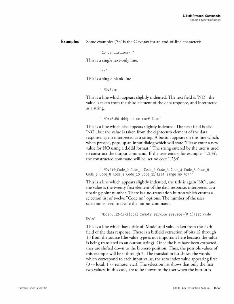
C-Link Protocol Commands Record Layout Definition
Thermo Fisher Scientific Model 48i Instruction Manual B-57
Some examples ('\n' is the C syntax for an end-of-line character):
'Concentrations\n'
This is a single text-only line.
'\n'
This is a single blank line.
' NO:3s\n'
This is a line which appears slightly indented. The text field is 'NO', the value is taken from the third element of the data response, and interpreted as a string.
' NO:18sBd.ddd;set no coef %s\n'
This is a line which also appears slightly indented. The next field is also 'NO', but the value is taken from the eighteenth element of the data response, again interpreted as a string. A button appears on this line which, when pressed, pops up an input dialog which will state "Please enter a new value for NO using a d.ddd format." The string entered by the user is used to construct the output command. If the user enters, for example, '1.234', the constructed command will be 'set no coef 1.234'.
' NO:21f{Code_0 Code_1 Code_2 Code_3 Code_4 Code_5 Code_6 Code_7 Code_8 Code_9 Code_10 Code_11}Lset range no %d\n'
This is a line which appears slightly indented, the title is again 'NO', and the value is the twenty-first element of the data response, interpreted as a floating-point number. There is a no-translation button which creates a selection list of twelve "Code nn" options. The number of the user selection is used to create the output command.
'Mode:6.12-13x{local remote service service}(0 1)Tset mode %s\n'
This is a line which has a title of 'Mode' and value taken from the sixth field of the data response. There is a bitfield extraction of bits 12 through 13 from the source (the value type is not important here because the value is being translated to an output string). Once the bits have been extracted, they are shifted down to the bit-zero position. Thus, the possible values of this example will be 0 through 3. The translation list shows the words which correspond to each input value, the zero index value appearing first (0 -> local, 1 -> remote, etc.). The selection list shows that only the first two values, in this case, are to be shown to the user when the button is
Examples
C-Link Protocol Commands Record Layout Definition
B-58 Model 48i Instruction Manual Thermo Fisher Scientific
pressed. The 'T' button indicates full translation, input code to string, and user selection number to output string.
'\xC'
This is a line that starts a new column (the \xC or ^L).
' Comp:6.11x{off on}Tset temp comp %s\n'
This shows that the bitfield end (the second part of a bitfield specification) is optional. The bitfield will be one bit long, starting in this case at the eleventh bit.
'Background:7f*8Bd.ddd;set o3 bkg %s\n'
This shows the use of indirect precision specifiers for floating point displays. The background value is taken from the 7th element, and the precision specifier is taken from the 8th. If the asterisk were not present, it would indicate instead that 8 digits after the decimal point should be displayed.
Thermo Fisher Scientific Model 48i Instruction Manual C-1
Appendix C MODBUS Protocol
This appendix provides a description of the MODBUS Protocol Interface and is supported both over RS-232/485 (RTU protocol) as well as TCP/IP over Ethernet.
The MODBUS commands that are implemented are explained in detail in this document. The MODBUS protocol support for the iSeries enables the user to perform the functions of reading the various concentrations and other measurement values, read the status of the digital outputs of the analyzer, and to trigger or simulate the activation of a digital input to the instrument. This is achieved by using the supported MODBUS parameters listed below.
For details of the Model 48i MODBUS Protocol specification, see the following topics:
● “Serial Communication Parameters” on page C-1
● “TCP Communication Parameters” on page C-2
● “Application Data Unit Definition” on page C-2
● “Function Codes” on page C-3
● “MODBUS Parameters Supported” on page C-8
Additional information on the MODBUS protocol can be obtained at http://www.modbus.org. References are from MODBUS Application Protocol Specification V1.1a MODBUS-IDA June 4, 2004.
The following are the communication parameters that are used to configure the serial port of the iSeries to support MODBUS RTU protocol.
Number of Data bits : 7 or 8
Number of Stop bits : 1 or 2
Parity : None, Odd, or Even
Data rate : 1200 to 115200 Baud (9600 is default)
Serial Communication
Parameters
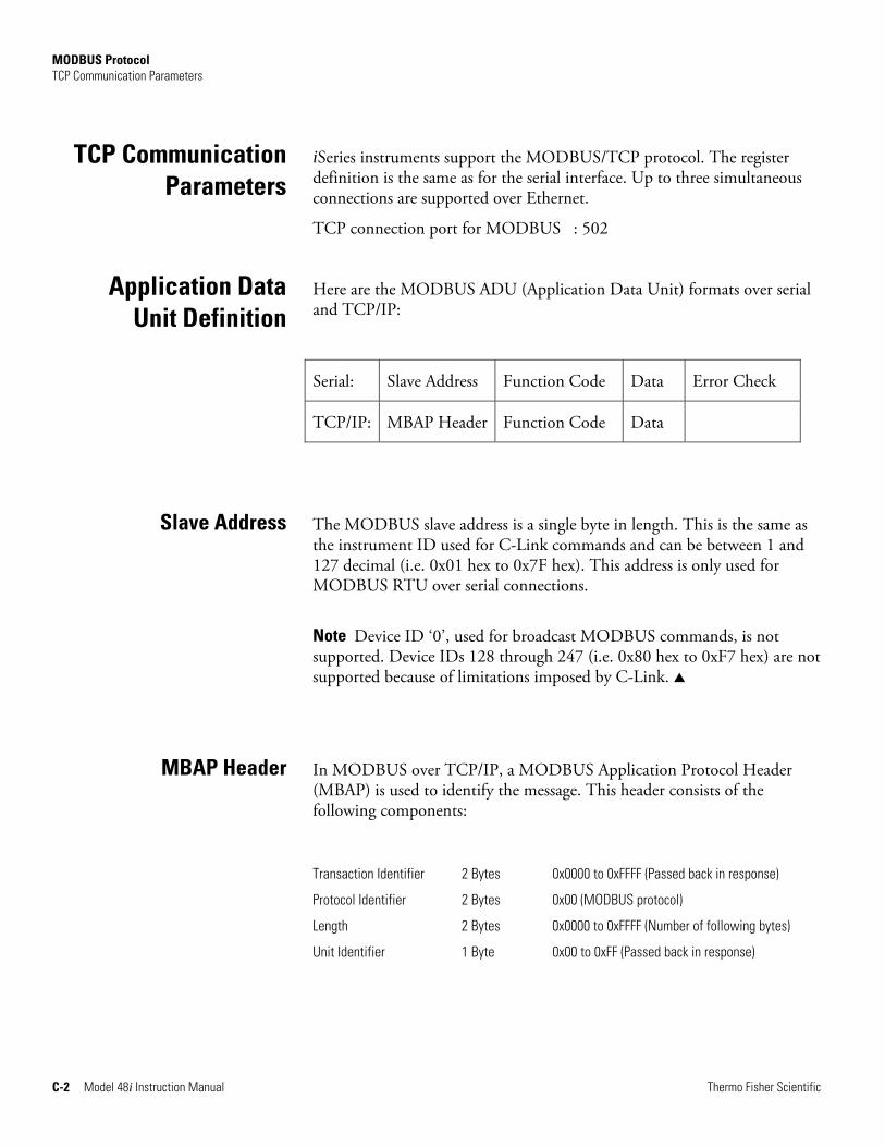
MODBUS Protocol TCP Communication Parameters
C-2 Model 48i Instruction Manual Thermo Fisher Scientific
iSeries instruments support the MODBUS/TCP protocol. The register definition is the same as for the serial interface. Up to three simultaneous connections are supported over Ethernet.
TCP connection port for MODBUS : 502
Here are the MODBUS ADU (Application Data Unit) formats over serial and TCP/IP:
Serial: Slave Address Function Code Data Error Check
TCP/IP: MBAP Header Function Code Data
The MODBUS slave address is a single byte in length. This is the same as the instrument ID used for C-Link commands and can be between 1 and 127 decimal (i.e. 0x01 hex to 0x7F hex). This address is only used for MODBUS RTU over serial connections.
Note Device ID ‘0’, used for broadcast MODBUS commands, is not supported. Device IDs 128 through 247 (i.e. 0x80 hex to 0xF7 hex) are not supported because of limitations imposed by C-Link. ▲
In MODBUS over TCP/IP, a MODBUS Application Protocol Header (MBAP) is used to identify the message. This header consists of the following components:
Transaction Identifier 2 Bytes 0x0000 to 0xFFFF (Passed back in response)
Protocol Identifier 2 Bytes 0x00 (MODBUS protocol)
Length 2 Bytes 0x0000 to 0xFFFF (Number of following bytes)
Unit Identifier 1 Byte 0x00 to 0xFF (Passed back in response)
TCP Communication Parameters
Application Data Unit Definition
Slave Address
MBAP Header
MODBUS Protocol Function Codes
Thermo Fisher Scientific Model 48i Instruction Manual C-3
A slave address is not required in MODBUS over TCP/IP because the higher-level protocols include device addressing. The unit identifier is not used by the instrument.
The function code is a single byte in length. The following function codes are supported by the instrument:
Read Coils : 0x01
Read Inputs : 0x02
Read Holding Registers : 0x03
Read Input Registers : 0x04
Force (Write) Single Coil : 0x05
Read Exception Status : 0x06
If a function code is received that is not in this list, an invalid function exception is returned.
The data field varies depending on the function. For more description of these data fields, see “Function Codes” below.
In MODBUS over serial, an error check is included in the message. This is not necessary in MODBUS over TCP/IP because the higher-level protocols ensure error-free transmission. The error check is a two-byte (16 bit) CRC value.
This section describes the various function codes that are supported by the Model 48i.
Read Coils/Inputs read the status of the digital outputs (relays) in the instrument. Issuing either of these function codes will generate the same response.
These requests specify the starting address, i.e. the address of the first output specified, and the number of outputs. The outputs are addressed starting at zero. Therefore, outputs numbered 1–16 are addressed as 0–15.
Function Code
Data
Error Check
Function Codes
(0x01/0x02) Read Coils/Read Inputs
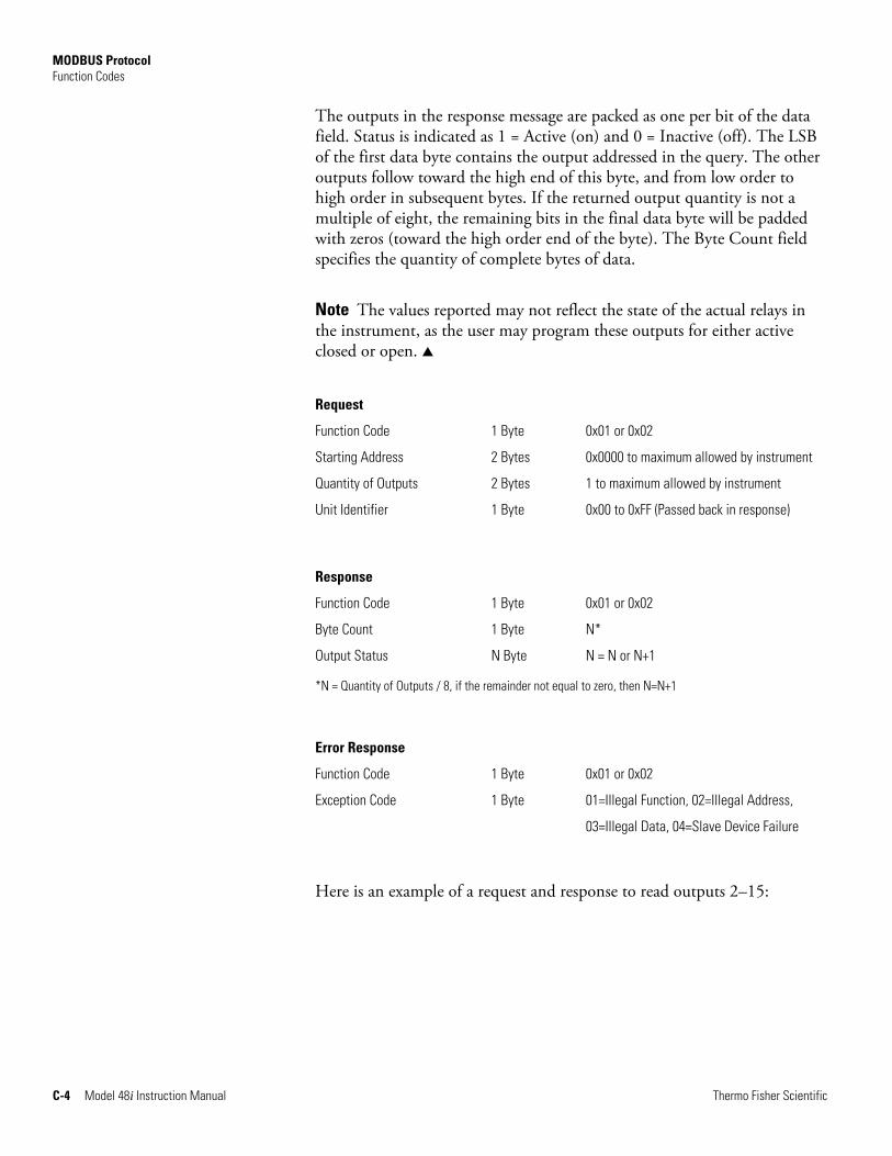
MODBUS Protocol Function Codes
C-4 Model 48i Instruction Manual Thermo Fisher Scientific
The outputs in the response message are packed as one per bit of the data field. Status is indicated as 1 = Active (on) and 0 = Inactive (off). The LSB of the first data byte contains the output addressed in the query. The other outputs follow toward the high end of this byte, and from low order to high order in subsequent bytes. If the returned output quantity is not a multiple of eight, the remaining bits in the final data byte will be padded with zeros (toward the high order end of the byte). The Byte Count field specifies the quantity of complete bytes of data.
Note The values reported may not reflect the state of the actual relays in the instrument, as the user may program these outputs for either active closed or open. ▲
Request
Function Code 1 Byte 0x01 or 0x02
Starting Address 2 Bytes 0x0000 to maximum allowed by instrument
Quantity of Outputs 2 Bytes 1 to maximum allowed by instrument
Unit Identifier 1 Byte 0x00 to 0xFF (Passed back in response)
Response
Function Code 1 Byte 0x01 or 0x02
Byte Count 1 Byte N*
Output Status N Byte N = N or N+1
*N = Quantity of Outputs / 8, if the remainder not equal to zero, then N=N+1
Error Response
Function Code 1 Byte 0x01 or 0x02
Exception Code 1 Byte 01=Illegal Function, 02=Illegal Address,
03=Illegal Data, 04=Slave Device Failure
Here is an example of a request and response to read outputs 2–15:
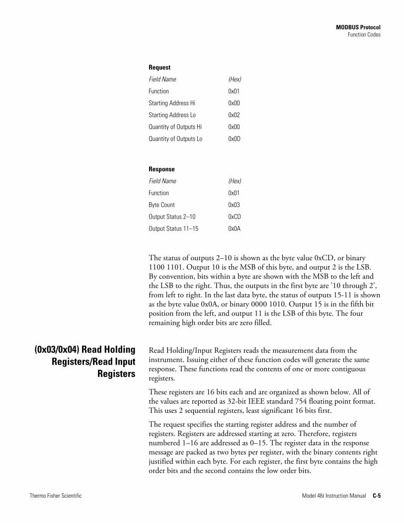
MODBUS Protocol Function Codes
Thermo Fisher Scientific Model 48i Instruction Manual C-5
Request
Field Name (Hex)
Function 0x01
Starting Address Hi 0x00
Starting Address Lo 0x02
Quantity of Outputs Hi 0x00
Quantity of Outputs Lo 0x0D
Response
Field Name (Hex)
Function 0x01
Byte Count 0x03
Output Status 2–10 0xCD
Output Status 11–15 0x0A
The status of outputs 2–10 is shown as the byte value 0xCD, or binary 1100 1101. Output 10 is the MSB of this byte, and output 2 is the LSB. By convention, bits within a byte are shown with the MSB to the left and the LSB to the right. Thus, the outputs in the first byte are ’10 through 2’, from left to right. In the last data byte, the status of outputs 15-11 is shown as the byte value 0x0A, or binary 0000 1010. Output 15 is in the fifth bit position from the left, and output 11 is the LSB of this byte. The four remaining high order bits are zero filled.
Read Holding/Input Registers reads the measurement data from the instrument. Issuing either of these function codes will generate the same response. These functions read the contents of one or more contiguous registers.
These registers are 16 bits each and are organized as shown below. All of the values are reported as 32-bit IEEE standard 754 floating point format. This uses 2 sequential registers, least significant 16 bits first.
The request specifies the starting register address and the number of registers. Registers are addressed starting at zero. Therefore, registers numbered 1–16 are addressed as 0–15. The register data in the response message are packed as two bytes per register, with the binary contents right justified within each byte. For each register, the first byte contains the high order bits and the second contains the low order bits.
(0x03/0x04) Read HoldingRegisters/Read Input
Registers
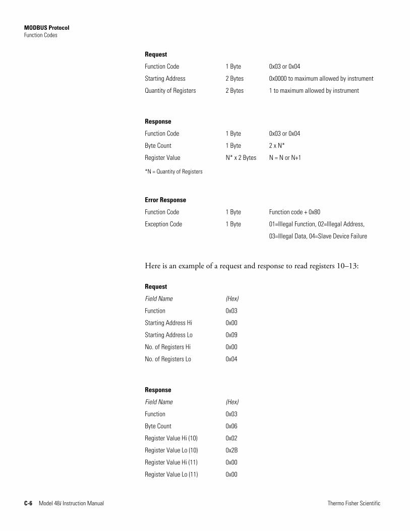
MODBUS Protocol Function Codes
C-6 Model 48i Instruction Manual Thermo Fisher Scientific
Request
Function Code 1 Byte 0x03 or 0x04
Starting Address 2 Bytes 0x0000 to maximum allowed by instrument
Quantity of Registers 2 Bytes 1 to maximum allowed by instrument
Response
Function Code 1 Byte 0x03 or 0x04
Byte Count 1 Byte 2 x N*
Register Value N* x 2 Bytes N = N or N+1
*N = Quantity of Registers
Error Response
Function Code 1 Byte Function code + 0x80
Exception Code 1 Byte 01=Illegal Function, 02=Illegal Address,
03=Illegal Data, 04=Slave Device Failure
Here is an example of a request and response to read registers 10–13:
Request
Field Name (Hex)
Function 0x03
Starting Address Hi 0x00
Starting Address Lo 0x09
No. of Registers Hi 0x00
No. of Registers Lo 0x04
Response
Field Name (Hex)
Function 0x03
Byte Count 0x06
Register Value Hi (10) 0x02
Register Value Lo (10) 0x2B
Register Value Hi (11) 0x00
Register Value Lo (11) 0x00
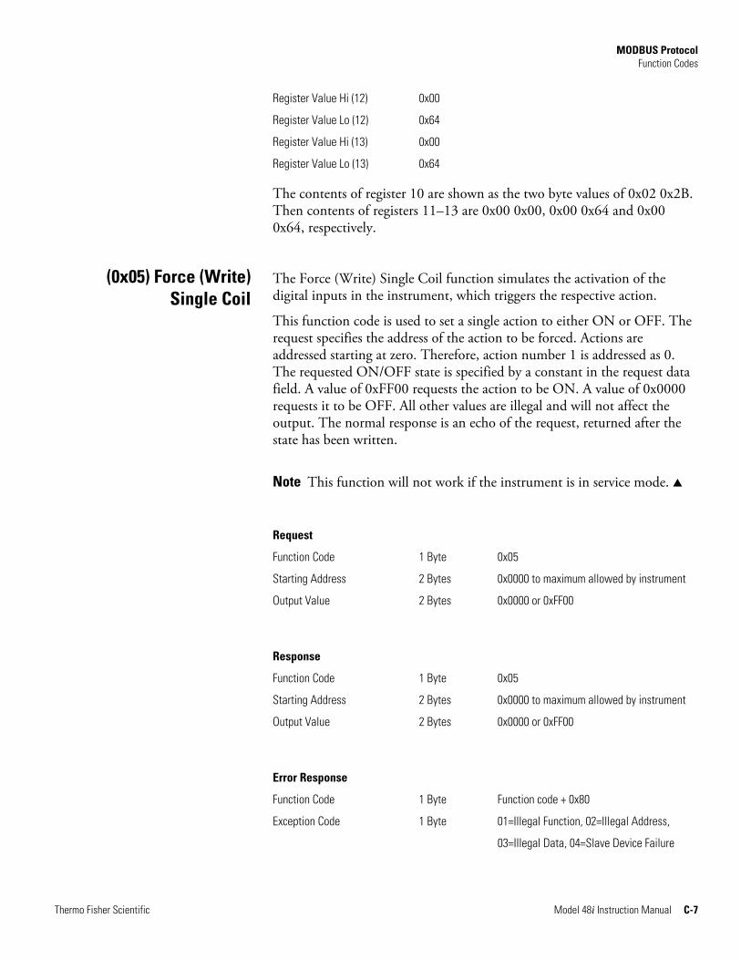
MODBUS Protocol Function Codes
Thermo Fisher Scientific Model 48i Instruction Manual C-7
Register Value Hi (12) 0x00
Register Value Lo (12) 0x64
Register Value Hi (13) 0x00
Register Value Lo (13) 0x64
The contents of register 10 are shown as the two byte values of 0x02 0x2B. Then contents of registers 11–13 are 0x00 0x00, 0x00 0x64 and 0x00 0x64, respectively.
The Force (Write) Single Coil function simulates the activation of the digital inputs in the instrument, which triggers the respective action.
This function code is used to set a single action to either ON or OFF. The request specifies the address of the action to be forced. Actions are addressed starting at zero. Therefore, action number 1 is addressed as 0. The requested ON/OFF state is specified by a constant in the request data field. A value of 0xFF00 requests the action to be ON. A value of 0x0000 requests it to be OFF. All other values are illegal and will not affect the output. The normal response is an echo of the request, returned after the state has been written.
Note This function will not work if the instrument is in service mode. ▲
Request
Function Code 1 Byte 0x05
Starting Address 2 Bytes 0x0000 to maximum allowed by instrument
Output Value 2 Bytes 0x0000 or 0xFF00
Response
Function Code 1 Byte 0x05
Starting Address 2 Bytes 0x0000 to maximum allowed by instrument
Output Value 2 Bytes 0x0000 or 0xFF00
Error Response
Function Code 1 Byte Function code + 0x80
Exception Code 1 Byte 01=Illegal Function, 02=Illegal Address,
03=Illegal Data, 04=Slave Device Failure
(0x05) Force (Write) Single Coil
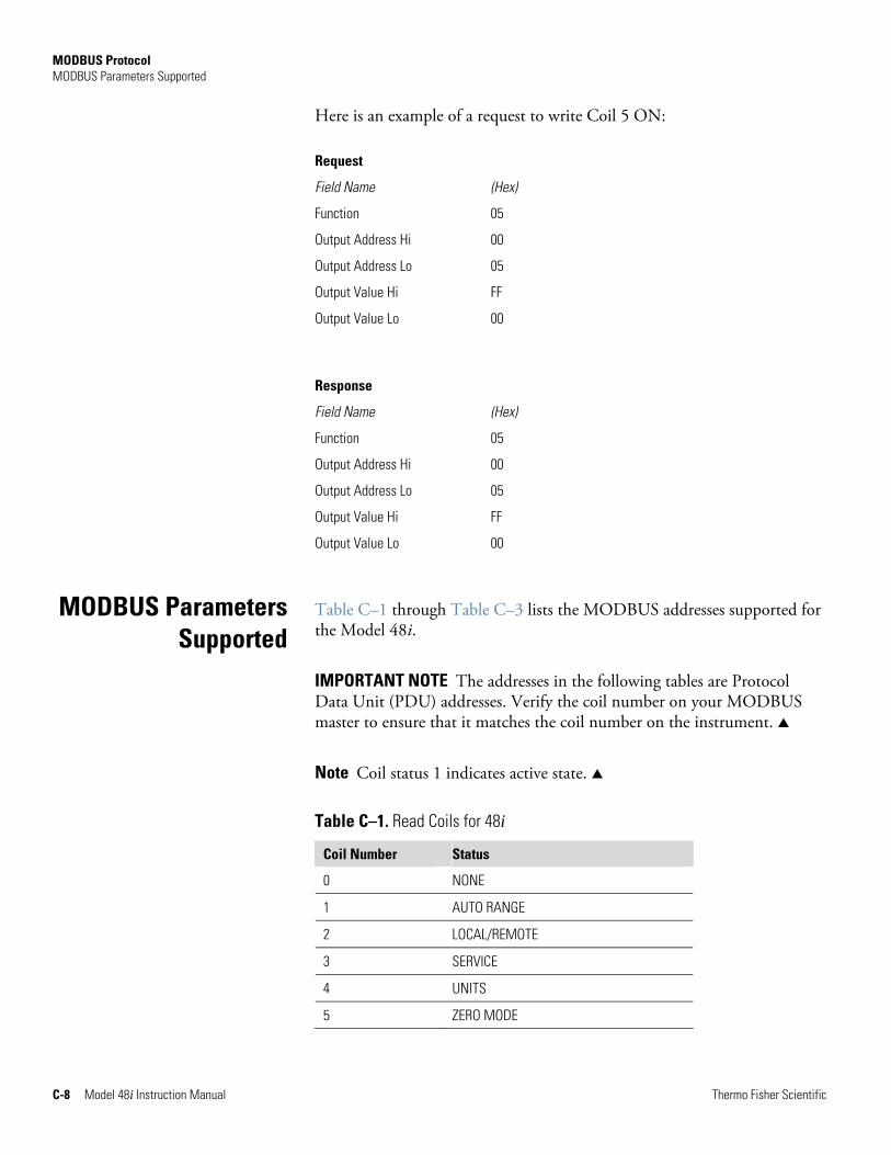
MODBUS Protocol MODBUS Parameters Supported
C-8 Model 48i Instruction Manual Thermo Fisher Scientific
Here is an example of a request to write Coil 5 ON:
Request
Field Name (Hex)
Function 05
Output Address Hi 00
Output Address Lo 05
Output Value Hi FF
Output Value Lo 00
Response
Field Name (Hex)
Function 05
Output Address Hi 00
Output Address Lo 05
Output Value Hi FF
Output Value Lo 00
Table C–1 through Table C–3 lists the MODBUS addresses supported for the Model 48i.
IMPORTANT NOTE The addresses in the following tables are Protocol Data Unit (PDU) addresses. Verify the coil number on your MODBUS master to ensure that it matches the coil number on the instrument. ▲
Note Coil status 1 indicates active state. ▲
Table C–1. Read Coils for 48i
Coil Number Status
0 NONE
1 AUTO RANGE
2 LOCAL/REMOTE
3 SERVICE
4 UNITS
5 ZERO MODE
MODBUS Parameters Supported
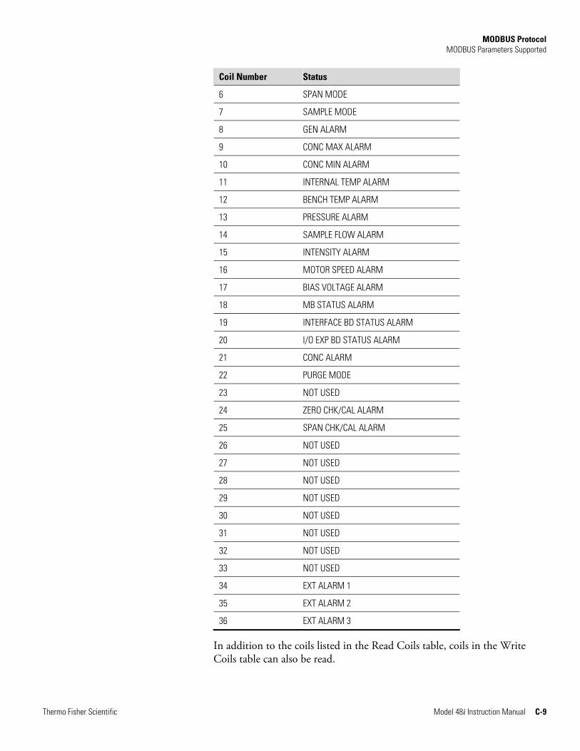
MODBUS Protocol MODBUS Parameters Supported
Thermo Fisher Scientific Model 48i Instruction Manual C-9
Coil Number Status
6 SPAN MODE
7 SAMPLE MODE
8 GEN ALARM
9 CONC MAX ALARM
10 CONC MIN ALARM
11 INTERNAL TEMP ALARM
12 BENCH TEMP ALARM
13 PRESSURE ALARM
14 SAMPLE FLOW ALARM
15 INTENSITY ALARM
16 MOTOR SPEED ALARM
17 BIAS VOLTAGE ALARM
18 MB STATUS ALARM
19 INTERFACE BD STATUS ALARM
20 I/O EXP BD STATUS ALARM
21 CONC ALARM
22 PURGE MODE
23 NOT USED
24 ZERO CHK/CAL ALARM
25 SPAN CHK/CAL ALARM
26 NOT USED
27 NOT USED
28 NOT USED
29 NOT USED
30 NOT USED
31 NOT USED
32 NOT USED
33 NOT USED
34 EXT ALARM 1
35 EXT ALARM 2
36 EXT ALARM 3
In addition to the coils listed in the Read Coils table, coils in the Write Coils table can also be read.
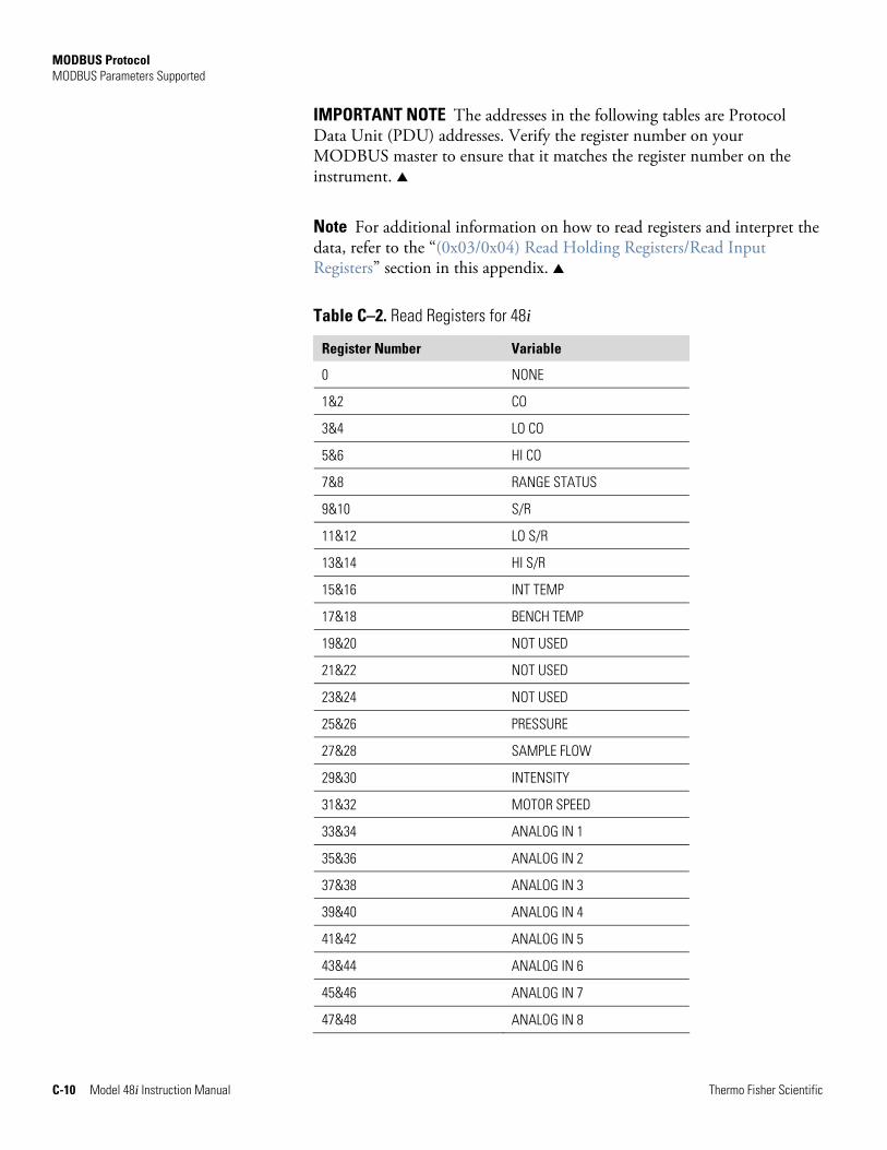
MODBUS Protocol MODBUS Parameters Supported
C-10 Model 48i Instruction Manual Thermo Fisher Scientific
IMPORTANT NOTE The addresses in the following tables are Protocol Data Unit (PDU) addresses. Verify the register number on your MODBUS master to ensure that it matches the register number on the instrument. ▲
Note For additional information on how to read registers and interpret the data, refer to the “(0x03/0x04) Read Holding Registers/Read Input Registers” section in this appendix. ▲
Table C–2. Read Registers for 48i
Register Number Variable
0 NONE
1&2 CO
3&4 LO CO
5&6 HI CO
7&8 RANGE STATUS
9&10 S/R
11&12 LO S/R
13&14 HI S/R
15&16 INT TEMP
17&18 BENCH TEMP
19&20 NOT USED
21&22 NOT USED
23&24 NOT USED
25&26 PRESSURE
27&28 SAMPLE FLOW
29&30 INTENSITY
31&32 MOTOR SPEED
33&34 ANALOG IN 1
35&36 ANALOG IN 2
37&38 ANALOG IN 3
39&40 ANALOG IN 4
41&42 ANALOG IN 5
43&44 ANALOG IN 6
45&46 ANALOG IN 7
47&48 ANALOG IN 8
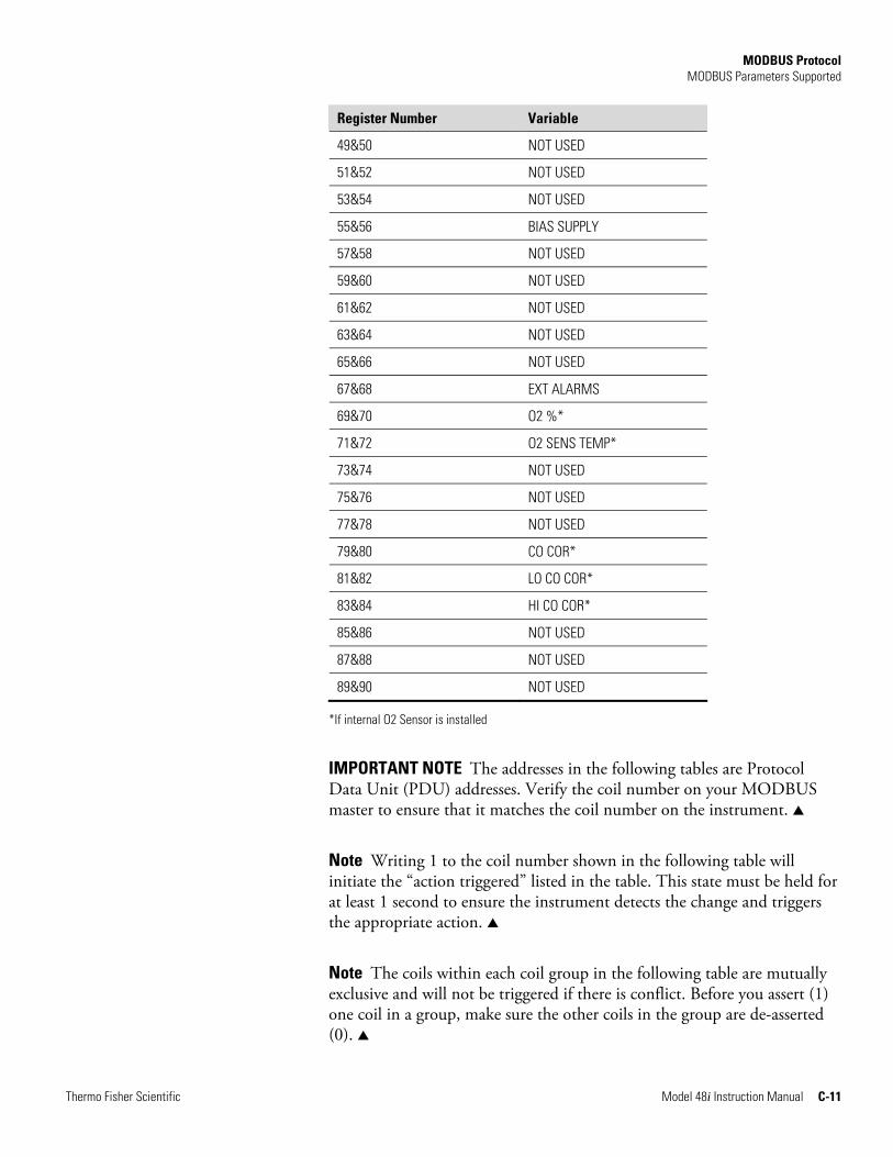
MODBUS Protocol MODBUS Parameters Supported
Thermo Fisher Scientific Model 48i Instruction Manual C-11
Register Number Variable
49&50 NOT USED
51&52 NOT USED
53&54 NOT USED
55&56 BIAS SUPPLY
57&58 NOT USED
59&60 NOT USED
61&62 NOT USED
63&64 NOT USED
65&66 NOT USED
67&68 EXT ALARMS
69&70 O2 %*
71&72 O2 SENS TEMP*
73&74 NOT USED
75&76 NOT USED
77&78 NOT USED
79&80 CO COR*
81&82 LO CO COR*
83&84 HI CO COR*
85&86 NOT USED
87&88 NOT USED
89&90 NOT USED
*If internal O2 Sensor is installed
IMPORTANT NOTE The addresses in the following tables are Protocol Data Unit (PDU) addresses. Verify the coil number on your MODBUS master to ensure that it matches the coil number on the instrument. ▲
Note Writing 1 to the coil number shown in the following table will initiate the “action triggered” listed in the table. This state must be held for at least 1 second to ensure the instrument detects the change and triggers the appropriate action. ▲
Note The coils within each coil group in the following table are mutually exclusive and will not be triggered if there is conflict. Before you assert (1) one coil in a group, make sure the other coils in the group are de-asserted (0). ▲
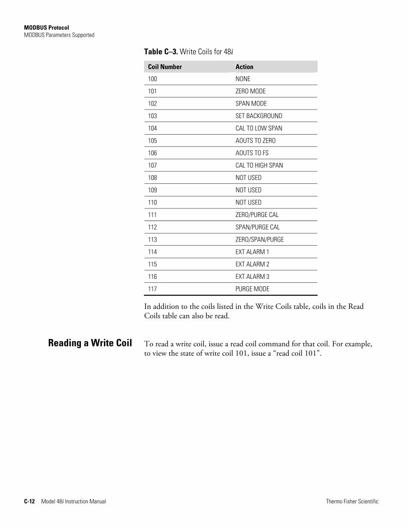
MODBUS Protocol MODBUS Parameters Supported
C-12 Model 48i Instruction Manual Thermo Fisher Scientific
Table C–3. Write Coils for 48i
Coil Number Action
100 NONE
101 ZERO MODE
102 SPAN MODE
103 SET BACKGROUND
104 CAL TO LOW SPAN
105 AOUTS TO ZERO
106 AOUTS TO FS
107 CAL TO HIGH SPAN
108 NOT USED
109 NOT USED
110 NOT USED
111 ZERO/PURGE CAL
112 SPAN/PURGE CAL
113 ZERO/SPAN/PURGE
114 EXT ALARM 1
115 EXT ALARM 2
116 EXT ALARM 3
117 PURGE MODE
In addition to the coils listed in the Write Coils table, coils in the Read Coils table can also be read.
To read a write coil, issue a read coil command for that coil. For example, to view the state of write coil 101, issue a “read coil 101”.
Reading a Write Coil
Thermo Fisher Scientific Model 48i Instruction Manual D-1
Appendix D Gesytec (Bayern-Hessen) Protocol
This appendix provides a description of the Gesytec (Bayern-Hessen or BH) Protocol Interface and is supported both over RS-232/485 as well as TCP/IP over Ethernet.
The Gesytec commands that are implemented are explained in detail in this document. The Gesytec protocol support for the iSeries enables the user to perform the functions of reading the various concentrations and to trigger the instrument to be in sample/zero/span mode if valid for that instrument. This is achieved by using the supported Gesytec commands listed below.
For details of the Model 48i Gesytec Protocol specification, see the following topics:
● “Serial Communication Parameters” on page D-1
● “TCP Communication Parameters” on page D-2
● “Instrument Address” on page D-2
● "Abbreviations Used” on page D-2
● “Basic Command Structure” on page D-2
● “Block Checksum Characters <BCC>” on page D-3
● “Gesytec Commands” on page D-3
The following are the communication parameters that are used to configure the serial port of the iSeries to support Gesytec protocol.
Number of Data bits : 7 or 8
Number of Stop bits : 1 or 2
Parity : None, Odd, or Even
Data rate : 1200 to 115200 Baud (9600 is default)
Serial Communication Parameters
Gesytec (Bayern-Hessen) Protocol TCP Communication Parameters
D-2 Model 48i Instruction Manual Thermo Fisher Scientific
iSeries instruments support the Gesytec protocol over TCP/IP. The register definition is the same as for the serial interface. Up to three simultaneous connections are supported over Ethernet.
TCP connection port for Gesytec: 9882
The Gesytec instrument address has a value between 0 and 127 and is represented by a 3 digit ASCII number with leading zeros or leading spaces if required (e.g. instrument address of 1 is represented as 001 or <SP><SP>1).
The instrument address is the same as the Instrument ID used for C-Link and MODBUS commands. This can be set via the front panel.
The instrument address is represented by <address> in the examples throughout this document.
Note Device IDs 128 through 247 are not supported because of limitations imposed by the C-Link protocol. ▲
The following is a list of abbreviations used in this document:
<CR> is abbreviation for Carriage Return (ASCII code 0x0D)
<STX> is abbreviation for Start of Text (ASCII code 0x02)
<ETX> is abbreviation for End of Text (ASCII code 0x03)
<SP> is abbreviation for space (ASCII code 0x20)
The following is the basic structure of a Gesytec command:
<STX>Command text<ETX><BCC>
OR
<STX>Command text<CR>
Each command is framed by control characters, <STX> at the start and terminated with either <ETX> or <CR>.
If a command is terminated with <ETX>, then two additional characters <BCC> is attached after <ETX>. This is the block checksum.
Block Checksum Characters <BCC> may be added to the command to prevent processing invalid commands.
TCP Communication Parameters
Instrument Address
Abbreviations Used
Basic Command Structure
Gesytec (Bayern-Hessen) Protocol Block Checksum Characters <BCC>
Thermo Fisher Scientific Model 48i Instruction Manual D-3
The Block Checksum Characters are calculated beginning with a seed value of 00000000, binary (0x00), and bitwise exclusive ORing with each of the characters of the command string (or response) including the framing characters <STX> and <ETX>. The checksum works as an error check. The command terminator determines the presence or absence of <BCC>.
If a command is terminated by <ETX> then the next two characters are the checksum, if the command is terminated with <CR> no checksum is attached.
The block checksum is represented by two characters, which represent a 2 digit hex number (1byte) (e.g. 1 byte 0xAB hex checksum will be represented by the two characters ‘A’ & ‘B’).
The checksum is referred to as <BCC> throughout this document.
The following commands are supported by the Gesytec protocol:
● Instrument Control Command (ST)
● Data Sampling/Data Query Command (DA)
There are three control commands supported by the Gesytec protocol.
This <control command> is a single letter, which triggers an action in the instrument. These commands are active only when service mode is inactive and the zero/span option is present.
Command ‘N’ switches the instrument gas mode to Zero mode.
Command ‘K’ switches the instrument gas mode to Span mode.
Command ‘M’ switches the instrument gas mode to Sample mode.
The following are the different acceptable formats of the ST command:
<STX>ST<address><control command><ETX><BCC>
OR
<STX>ST<address><control command><CR>
OR
<STX>ST<address><SP><control command><CR>
OR
<STX>ST<address><SP><control command><ETX><BCC>
Block Checksum Characters <BCC>
Gesytec Commands
Instrument Control Command (ST)
Gesytec (Bayern-Hessen) Protocol Gesytec Commands
D-4 Model 48i Instruction Manual Thermo Fisher Scientific
The <address> is optional, which means it can be left out completely. The <address>, if present, must match the Instrument Address. Additional space can be present after the <address>.
If the received command does not satisfy the above formats, or if the <address> does not match the Instrument Address, the command is ignored.
This is a sample command to switch the instrument to zero mode, instrument address 5:
<STX>ST005<SP>N<CR>
This command nitiates a data transfer from the instrument. The instrument responds with measurement data, which depends on the range mode and is listed in “Measurements reported in response to DA command” below.
The command structure for a data query command is as follows:
<STX>DA<address><ETX><BCC>
The <address> is optional, which means it can be left out completely. The <address>, if present, must match the Instrument Address. Additional space can be present after the <address>.
If the <address> is left out, then no space is allowed in the query string.
A command with no address is also a valid command.
The following are the different acceptable formats of the DA command with Instrument Address 5:
<STX>DA<CR>
<STX>DA005<CR>
<STX>DA<SP><SP>5<ETX><BCC>
<STX>DA<ETX><BCC>
The data query string is valid and will be answered with data transmission only if the command starts with <STX>, which is followed by the characters DA, and the <address> (if present) matches the Instrument Address, and the command is terminated with either <CR> with no checksum or <ETX>, followed by the correct checksum <BCC>.
Data Sampling/Data Query Command
(DA)
Gesytec (Bayern-Hessen) Protocol Gesytec Commands
Thermo Fisher Scientific Model 48i Instruction Manual D-5
Sample Data Reply String in response to Data Query Command (DA):
In response to a valid data query command, the instrument responds in the following format:
<STX>MD02<SP><address><SP><measured value1><SP><status><SP><SFKT><SP><address+1><SP><measured value2><SP ><status><SP><SFKT><ETX><BCC>
The response uses the same command terminators as used by the received command, i.e. if the received command was terminated with a <CR> then the response is terminated with <CR>, and if the command was terminated with a <ETX><BCC>, then the response is terminated with<ETX> and the computed checksum <BCC>.
The 02 after the MD indicates that two measurements are present in the reply string, 03 for three measurements and so on. This will also determine the length of the reply string.
<address> is the Instrument Address. Each subsequent measurement attached to the response will have the <address + X>, where X keeps incrementing by 1 for each measurement included.
<measured value> is the concentration value in currently selected gas units, represented as exponential representation with 4 characters mantissa and 2 characters exponent, each with sign.
Mantissa: sign and 4 digits. The decimal point is assumed to be after the first digit and is not transmitted.
Exponent: sign and 2 digits.
Example:
-5384000.0 is represented as -5384+06
+0.04567 is represented as +4567-02
<status>: is formed by < operating status > and < error status > and separated by a space, i.e.:
<operating status><SP><error status>
Each of the two (<operating status> and <error status>) are formed by two characters, each representing a 2 digit hex number which is one byte (8 Bits) operation status and one byte (8 Bits) error status.
These two bytes contain the information about the main operating conditions of the instrument at that instant. For details on how to interpret the status bytes, refer to Table D–1 and Table D–2 below.
<SFKT>: is the space provided for future use for special function. It currently contains a string of ten 0’s, i.e. <0000000000>.
Gesytec (Bayern-Hessen) Protocol Gesytec Commands
D-6 Model 48i Instruction Manual Thermo Fisher Scientific
The Gesytec serial number defaults to zero. To set the Gesytec serial number select Main Menu > Instrument Controls > Communication Settings > Gesytec Serial No.
Example of response to DA command from an instrument with Gesytec serial number set to 000. The Gesytec serial number is bold in the example.
Gesytec Protocol with transmission of three concentrations (Instrument ID is 1, Operation Status is 03, Error Status is 04):
Data Query String: <STX>DA<CR>
Reply String: <STX>MD03<SP>001<SP>+2578+01<SP>03 <SP>04<SP>0000000000 <SP>002 <SP> ↑ ↑ ↑ Address First Concentration(E-format)=25.78 Address+1
+5681+00<SP>03<SP>04<SP>0000000000<SP>003<SP>+1175+01<SP>03<SP>04<SP ↑ ↑ ↑ Second Concentration = 5.681 Address+2 Third Concentration=11.75
0000000000<SP><CR>
Example of response to DA command from an instrument with Gesytec serial number set to 123.
Data Query String: <STX>DA<CR>
Reply String: <STX>MD03<SP>001<SP>+2578+01<SP>03 <SP>04<SP>1230000000 <SP>002 <SP> ↑ ↑ ↑ Address First Concentration(E-format)=25.78 Address+1
+5681+00<SP>03<SP>04<SP>1230000000<SP>003<SP>+1175+01<SP>03<SP>04<SP ↑ ↑ ↑ Second Concentration = 5.681 Address+2 Third Concentration=11.75
1230000000<SP><CR>
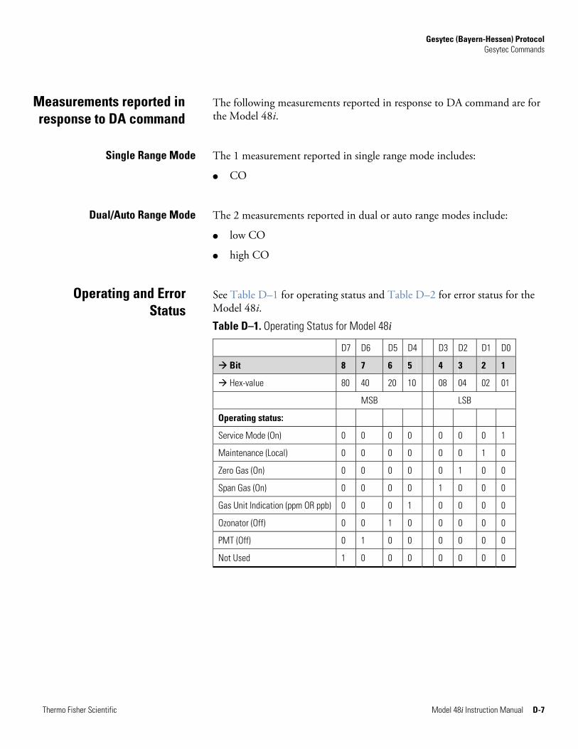
Gesytec (Bayern-Hessen) Protocol Gesytec Commands
Thermo Fisher Scientific Model 48i Instruction Manual D-7
The following measurements reported in response to DA command are for the Model 48i.
The 1 measurement reported in single range mode includes:
● CO
The 2 measurements reported in dual or auto range modes include:
● low CO
● high CO
See Table D–1 for operating status and Table D–2 for error status for the Model 48i.
Table D–1. Operating Status for Model 48i
D7 D6 D5 D4 D3 D2 D1 D0
Bit 8 7 6 5 4 3 2 1
Hex-value 80 40 20 10 08 04 02 01
MSB LSB
Operating status:
Service Mode (On) 0 0 0 0 0 0 0 1
Maintenance (Local) 0 0 0 0 0 0 1 0
Zero Gas (On) 0 0 0 0 0 1 0 0
Span Gas (On) 0 0 0 0 1 0 0 0
Gas Unit Indication (ppm OR ppb) 0 0 0 1 0 0 0 0
Ozonator (Off) 0 0 1 0 0 0 0 0
PMT (Off) 0 1 0 0 0 0 0 0
Not Used 1 0 0 0 0 0 0 0
Measurements reported in response to DA command
Single Range Mode
Dual/Auto Range Mode
Operating and Error Status
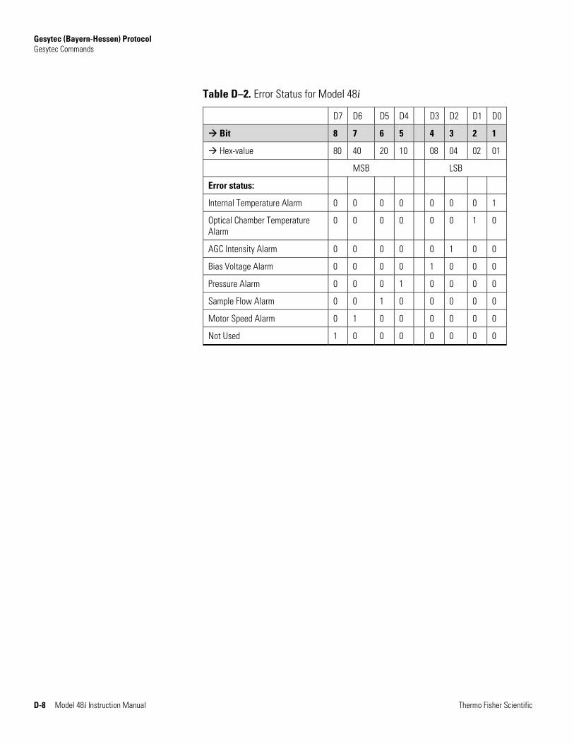
Gesytec (Bayern-Hessen) Protocol Gesytec Commands
D-8 Model 48i Instruction Manual Thermo Fisher Scientific
Table D–2. Error Status for Model 48i
D7 D6 D5 D4 D3 D2 D1 D0
Bit 8 7 6 5 4 3 2 1
Hex-value 80 40 20 10 08 04 02 01
MSB LSB
Error status:
Internal Temperature Alarm 0 0 0 0 0 0 0 1
Optical Chamber Temperature Alarm
0 0 0 0 0 0 1 0
AGC Intensity Alarm 0 0 0 0 0 1 0 0
Bias Voltage Alarm 0 0 0 0 1 0 0 0
Pressure Alarm 0 0 0 1 0 0 0 0
Sample Flow Alarm 0 0 1 0 0 0 0 0
Motor Speed Alarm 0 1 0 0 0 0 0 0
Not Used 1 0 0 0 0 0 0 0