Embed Size (px)
Citation preview
Ad-hoc Wireless Networking for Supporting
On-Site Communication
Linchuan Yang
A Thesis
in
The Concordia Institute for Information Systems Engineering
Presented in Partial Fulfillment of the Requirements For the Degree of Master of Applied Science (Quality Systems Engineering)
at Concordia University
Montreal, Quebec, Canada
December 2007
©Linchuan Yang, 2007

1*1 Library and Archives Canada
Published Heritage Branch
395 Wellington Street Ottawa ON K1A0N4 Canada
Bibliotheque et Archives Canada
Direction du Patrimoine de I'edition
395, rue Wellington Ottawa ON K1A0N4 Canada
Your file Votre reference ISBN: 978-0-494-40933-6 Our file Notre reference ISBN: 978-0-494-40933-6
NOTICE: The author has granted a nonexclusive license allowing Library and Archives Canada to reproduce, publish, archive, preserve, conserve, communicate to the public by telecommunication or on the Internet, loan, distribute and sell theses worldwide, for commercial or noncommercial purposes, in microform, paper, electronic and/or any other formats.
AVIS: L'auteur a accorde une licence non exclusive permettant a la Bibliotheque et Archives Canada de reproduire, publier, archiver, sauvegarder, conserver, transmettre au public par telecommunication ou par Plntemet, prefer, distribuer et vendre des theses partout dans le monde, a des fins commerciales ou autres, sur support microforme, papier, electronique et/ou autres formats.
The author retains copyright ownership and moral rights in this thesis. Neither the thesis nor substantial extracts from it may be printed or otherwise reproduced without the author's permission.
L'auteur conserve la propriete du droit d'auteur et des droits moraux qui protege cette these. Ni la these ni des extraits substantiels de celle-ci ne doivent etre imprimes ou autrement reproduits sans son autorisation.
In compliance with the Canadian Privacy Act some supporting forms may have been removed from this thesis.
Conformement a la loi canadienne sur la protection de la vie privee, quelques formulaires secondaires ont ete enleves de cette these.
While these forms may be included in the document page count, their removal does not represent any loss of content from the thesis.
Canada
Bien que ces formulaires aient inclus dans la pagination, il n'y aura aucun contenu manquant.

ABSTRACT
Ad-hoc Wireless Networking for Supporting On-Site Communication
Linchuan Yang
Ad-hoc networks are self-organized wireless networks. They have the potential to be
widely used in emergency salvation, construction sites, and military fields. However, the
research about the efficient usage of ad-hoc networking in engineering applications is still
limited. In this research, a new approach for investigating problems related to deploying
ad-hoc wireless networks for supporting on-site communication and collaboration is
proposed. Several modes of communication which are common in on-site applications
are considered including location information, text messaging, voice and video
communications, and file transmission. A prototype system is implemented for testing
these modes based on available ad-hoc network protocols and using mobile devices. In
addition, in order to verify our proposed approach, several tests are designed and
implemented to demonstrate the usefulness of the prototype system. The results from the
tests showed that our prototype system is applicable for ad-hoc wireless networks.
Furthermore, a new protocol based on clustering to improve data accessibility in ad-hoc
networks is tested using a simulation tool to study its performance under different
scenarios. The simulation results showed the impact of the area size, wireless range,
number of nodes, and node speed on data accessibility.
in

ACKNOWLEDGEMENTS
It is indeed a great pleasure for me to express my sincere appreciation and thanks to my
respectable supervisor Dr. Amin Hammad who gave me the opportunity to pursue my
Master's degree and provided the initial concept for this research project. His profound
knowledge and thoughtful instructions have always shed some light on my way to pursue
this thesis work.
I would like to extend my appreciation to Dr. Roch Glitho for his valuable guidance in
ad-hoc routing protocol. Furthermore, the work of Mr. Farrukh Mahboob and Mr. Talal
Ali Shwehdi (Master students of Electric Engineering Department, Concordia University)
in developing and running the simulation model is appreciated. And I also want to thank
the great help from Mr. Lei Guang and Miss Chunyan Fu (Ph.D. students of Electric
Engineering Department, Concordia University), Mr. Yan Huang (Master students of
Computer Science and Software Engineering Department, Concordia University), Mr.
Asanga Udugama (Researcher of University Bremen, Germany), and Mr. Sylvain
Robitaille (Systems and Network analyst of Concordia University).
During these two years of my study, the support of our Infra-group was of extreme
importance. I would like to thank Hui Wang, Cheng Zhang, Elaheh Mozaffari, and
Bechir Khabir for their help in the part for connecting with our 3D model.
Finally, I would like to thank my parents for their continuous encouragement and love.
You are my motivation to pursue my graduate study. Without your contributions, it was
impossible for me to succeed in this study.
iv

LIST OF FIGURES
TABLE OF CONTENTS
viii
LIST OF TABLES x
LIST OF ABBREVATIONS xi
CHAPTER 1 INTRODUCTION 1
1.1 GENERAL BACKGROUND 1
1.2 RESEARCH OBJECTIVES 2
1.3 THESIS ORGANIZATION 3
CHAPTER 2 LITERATURE REVIEW 4
2.1 WIRELESS NETWORKS 4
2.2 AD-HOC NETWORKS 8
2.2.1 CHARACTERISTICS OF AD-HOC NETWORKS 8
2.2.2 APPLICATIONS OF AD-HOC NETWORKS 10
2.2.3 SECURITY IN AD-HOC NETWORKS 10
2.2.4 QUALITY OF SERVICE (QoS) IN AD-HOC NETWORKS 11
2.3 ROUTING PROTOCOLS IN AD-HOC NETWORKS 15
2.4 IEEE 802.11 STANDARDS 16
2.5 NETWORK SIMULATION 18
2.6 DATA REPLICATION AND CLUSTERING IN AD-HOC NETWORKS 20
2.6.1 DATA REPLICATION IN AD-HOC NETWORKS 20
2.6.2 CLUSTERING IN AD-HOC NETWORKS 22
2.6.3 CLUSTER BASED REPLICA ALLOCATION (CBRA) 24
2.7 MOBILE AD-HOC TEST-BEDS 29
2.7.1 WIRELESS AD-HOC NETWORK TEST-BED IN DUBLIN 29
2.7.2 AD-HOC NETWORK TEST-BED AT UNIVERSITY OF
COLORADO 29
2.7.3 WIRELESS SHUTTLE BUS PROJECT AT JOHNS HOPKINS
UNIVERSITY (JHU) 30
2.7.4 WIRELESS DATA COLLECTION ON CONSTRUCTION SITES 31
v
2.7.5 MOBILE AD-HOC SPACE FOR COLLABORATION TO SUPPORT
DISASTER RELIEF EFFORTS 32
2.8 SUMMARY AND CONCLUSIONS 33
CHAPTER3 PROPOSED APPROACH 35
3.1 INTRODUCTION 35
3.2 PROPOSED SYSTEM FOR TESTING AD-HOC WIRELESS
COMMUNICATIONS 36
3.2.1 DESIGN LOGIC 37
3.2.2 NETWORK ROUTING 38
3.2.3 COMMUNICATION FUNCTIONS IN AD-HOC MESSENGER ... 41
3.2.4 PROPOSED TESTS 45
3.3 AD-HOC CLUSTERING SIMULATION 47
3.4 SUMMARY AND CONCLUSIONS 50
CHAPTER 4 IMPLEMENTATION AND TESTING 51
4.1 INTRODUCTION 51
4.2 SELECTION OF DEVELOPMENT TOOLS 51
4.3 IMPLEMENTATION OF THE PRTOTYPE SYSTEM 52
4.3.1 USER INTERFACE DEVELOPMENT 52
4.3.2 FUNCTIONS OF THE PROTOTYPE SYSTEM 55
4.4 TESTING THE AD-HOC MESSENGER 59
4.4.1 INITIAL TESTING 62
4.4.2 TEST-1: TEST WITH BRIDGE NODE 64
4.4.3 TEST-2: TEST USING AODV ROUTING PROTOCOL 65
4.5 CLUSTERING SIMULATION RESULTS 69
4.6 SUMMARY AND CONCLUSIONS 73
CHAPTER 5 SUMMARY, CONCLUSIONS, AND FUTURE WORK 75
5.1 SUMMARY 75
5.2 CONCLUSIONS AND CONTRIBUTIONS 76
5.3 FUTURE WORK 77
vi

REFERENCES 79
APPENDIX A SOFTWARE REQUIREMENTS AND INSTALLATION GUIDE
OF THE PROTOTYPE SYSTEM 86
APPENDIX B HARDWARE REQUIREMENTS AND CONFIGURATION
GUIDE OF THE PROTOTYPE SYSTEM 87
APPENDIX C SIMULATION TOOLS AND INSTALLATION GUIDE 92
APPENDIX D LIST OF PUBLICATIONS 102
vn
LIST OF FIGURES
Figure 2.1 Ad-hoc Networks 9
Figure 2.2 DCG Method 21
Figure 2.3 New Partitions in DCG Method 25
Figure 2.4 CBRA Algorithm 26
Figure 2.5 Clusters in CBRA Protocol 27
Figure 2.6 Node Communication through Cluster Heads 27
Figure 2.7 Flowchart of Data Access 28
Figure 2.8 Heterogeneous Ad-hoc Radio Nodes of Colorado 30
Figure 2.9 Shuttle Bus Project in JHU 31
Figure 2.10 Wireless Network Cell Configuration 31
Figure 2.11 Different Wireless Network Cell (WNC) 32
Figure 2.12 Shared Views for a First Response Team in a Simulated Disaster Area 33
Figure 2.13 Search and Rescue Exercise Supported by MASC System 33
Figure 3.1 System Design of Ad-hoc Messenger 37
Figure 3.2 Seven layers of Open Systems Interconnection (OSI) 38
Figure 3.3 Algorithm of JAdhoc Function 39
Figure 3.4 Communication between Two Clients in Ad-hoc Messenger 42
Figure 3.5 Text Messaging in Ad-hoc Messenger 43
Figure 3.6 File Transferring in Ad-hoc Messenger 44
Figure 3.7 Communication through a Bridge 46
Figure 3.8 Communication with AODV Routing Protocol 47
Figure 3.9 Simulation Animation 49
Figure 4.1 Start Window of Ad-hoc Messenger 52
Figure 4.2 JAdhoc Control Window 53
Figure 4.3 Main Control Panel of Ad-hoc Messenger 53
Figure 4.4 Position Messaging Control Window 54
Figure 4.5 Client to Client Monitor 55
Figure 4.6 Text Messaging 56
viii

Figure 4.7 Break Point Continue Transmission 57
Figure 4.8 Throughput Testing in Ad-hoc Messenger 59
Figure 4.9 Testing locations in the Fourth Floor of CB Building 60
Figure 4.10 Example of Distribution of Wireless nodes 61
Figure 4.11 Devices Used in the Prototype System Testing 61
Figure 4.12 Connection Speed of Wireless Adapter (g type) 62
Figure 4.13 Indoor Testing with Wireless Adapter (g type) 62
Figure 4.14 Probability Density Estimate Curve 63
Figure 4.15 Throughput of Bridge and AODV Tests (without walls) 67
Figure 4.16 Testing with Walls and without Walls 67
Figure 4.17 Example of Throughput Data When the Floor is not Crowded 67
Figure 4.18 Example of Throughput Data When the Floor is Crowded 68
Figure 4.19 Effects of Area size, Range, Node number, and Speed 70
Figure 4.20 Screenshots of a Simulation Animation 72
Figure B.l Advanced Configuration of Ad-hoc 87
Figure B.2 Configuration of Wireless Network 88
Figure B.3 Ad-hoc Wireless Network was Detected 89
Figure B.4 Joining an Existing Ad-hoc Wireless Network 89
Figure B.5 Configuration of JAdhoc 91
Figure C. 1 Simulation Terminal 100
Figure C.2 AODV Routing Protocol 100
Figure C.3 Simulation Scenario 100
Figure C.4 Simulation Program 100
Figure C.5 Simulation Result 101
Figure C.6 NAM 101
IX
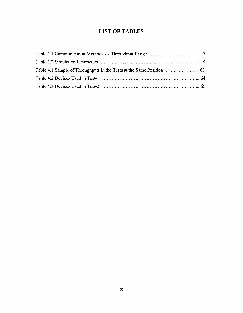
LIST OF TABLES
Table 3.1 Communication Methods vs. Throughput Range 45
Table 3.2 Simulation Parameters 48
Table 4.1 Sample of Throughputs in the Tests at the Same Position 63
Table 4.2 Devices Used in Test-1 64
Table 4.3 Devices Used in Test-2 66
x
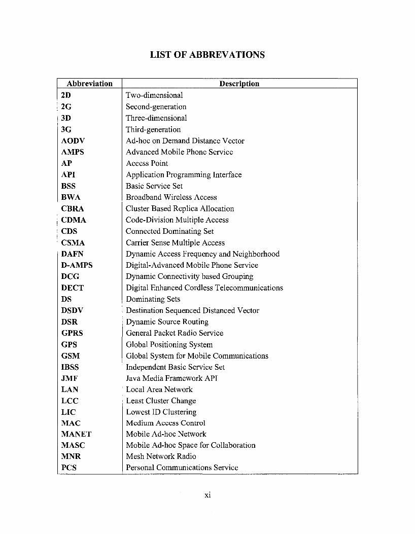
LIST OF ABBREVATIONS
Abbreviation
2D 2G 3D 3G AODV AMPS AP API BSS BWA CBRA CDMA CDS CSMA DAFN D-AMPS DCG DECT DS DSDV DSR GPRS GPS GSM IBSS JMF LAN LCC LIC MAC MANET MASC MNR PCS
Description Two-dimensional
Second-generation
Three-dimensional
Third-generation Ad-hoc on Demand Distance Vector Advanced Mobile Phone Service
Access Point
Application Programming Interface
Basic Service Set Broadband Wireless Access
Cluster Based Replica Allocation
Code-Division Multiple Access
Connected Dominating Set
Carrier Sense Multiple Access
Dynamic Access Frequency and Neighborhood Digital-Advanced Mobile Phone Service Dynamic Connectivity based Grouping
Digital Enhanced Cordless Telecommunications
Dominating Sets
Destination Sequenced Distanced Vector
Dynamic Source Routing
General Packet Radio Service
Global Positioning System
Global System for Mobile Communications
Independent Basic Service Set Java Media Framework API Local Area Network
Least Cluster Change Lowest ID Clustering Medium Access Control Mobile Ad-hoc Network Mobile Ad-hoc Space for Collaboration Mesh Network Radio
Personal Communications Service
XI

PDA
QoS RERR RREP RREQ RTP SAF SMS SSID TDMA TTL UAVs UHF VoIP VR W P N WCA WEP WiMAX WLAN WME WMM WNC ZRP
Personal Digital Assistant
Quality of Service
Route Error
Route Reply
Route request
Real-time Transport Protocol
Static Access Frequency
Short Message Service Service Set Identifier
Time Division Multiple Access Time To Live
Unmanned Aerial Vehicles
Ultra-high-frequency
Video and voice over IP
Virtual Reality Voice Virtual Private Network Weighted Cluster Algorithm
Wired Equivalent Privacy Worldwide Interoperability for Microwave Access
Wireless Local Area Networks Wireless Multimedia Extension
Wi-Fi Multimedia
Wireless Network Cells Zone Routing Protocol
xii

CHAPTER 1 INTRODUCTION
1.1 GENERAL BACKGROUND
Efficient collaboration among team members working in the field, such as inspection
teams, search and rescue teams after a disaster, and troops in the battle, is important to
realize the intended tasks. Real-time communication is necessary for those field workers
to enhance their collaborative efforts. Nowadays, several technologies are used on site,
such as cellular/mobile phones, digital enhanced cordless telecommunications (DECT),
voice virtual private networks (VVPN), wired local-area networks (LAN), and satellite
telecommunications. However, these technologies have some disadvantages, which may
affect the work on-site. Furthermore, all of the above technologies need some type of
infrastructure (e.g., wiring, routers, etc.). If the available infrastructure is damaged
because of natural or man-made disasters, all the on-site communications will stop, which
will lead to extra losses and, in some cases, additional casualties. Consequently, a
technique which does not need any infrastructures, and which is economical and efficient,
is needed.
Ad-hoc networking is an attractive solution for this problem because it allows field
workers using portable devices to communicate and keep in touch with each other when
they are performing their tasks. Many kinds of devices could be used as clients in an
ad-hoc wireless network, such as notebooks, tablet PCs, and PDAs. These devices have
wireless adapters with different standards (mainly IEEE 802.11a, b, and g), which include
encryption schemes to make the ad-hoc network as secure as the wired LAN.
1

Several research projects considered the usage of wireless networks to support on-site
communications, and some of them discussed a new approach to use ad-hoc networking
to support effective collaboration among first response organizations with high
performance of data accessibility. However, the research about the efficient usage of
ad-hoc networking in engineering applications is still limited. On the other hand, research
about new protocols aiming to improve the ad-hoc network performance is progressing
using several clustering and replication techniques. However, these protocols need
careful testing from the point-of-view of the engineering applications.
1.2 RESEARCH OBJECTIVES
This research aims to investigate the applicability of ad-hoc wireless networking for
supporting on-site communication. The research includes two parts: a prototype system
for supporting different communication methods using ad-hoc wireless networks and an
ad-hoc clustering simulation. The research has the following objectives:
(1) Defining the basic modes of communication which are common in on-site
applications;
(2) Implementing and testing these modes using a prototype system based on available
ad-hoc network protocols and using mobile devices; and
(3) Simulating the performance of a new protocol based on clustering to improve data
accessibility using different scenarios.
2

1.3 THESIS ORGANIZATION
This research will be presented as follows:
Chapter 2 Literature Review: This chapter presents most of the current wireless methods
for communication and collaboration. Many routing protocols for ad-hoc networks are
introduced, and a new approach of Cluster-based Replica Allocation (CBRA) is reviewed.
Furthermore, many popular simulation tools are compared. In addition, several test-beds
based on ad-hoc wireless networks are reviewed.
Chapter 3 Proposed approach: This chapter has two parts. In the first part, a system
design is presented for testing ad-hoc wireless communications. In order to test this
system, two types of tests are used with different routing solutions. In the second part,
simulation scenarios of a new clustering algorithm based on CBRA protocol to improve
data accessibility are presented.
Chapter 4 Implementation and testing: This chapter discusses the implementation details
of the proposed system called "Ad-hoc Messenger", the testing of this system, and the
simulation results of the CBRA protocol.
Chapter 5 Summary, Conclusions, and Future work: This Chapter summarizes the
presented research work, highlights the contributions, and suggests recommendations for
future research.
3
CHAPTER 2 LITERATURE REVIEW
2.1 WIRELESS NETWORKS
Wireless networks follow several standards such as IEEE 802.11. A basic such wireless
network consists of multiple stations communicating (enabling file sharing, printer
sharing, Internet connection, etc.) with radios that broadcast in either the 2.4 GHz or 5
GHz band. While the term wireless network may technically be used to refer to any type
of network that is wireless, the term is most commonly used to refer to a
telecommunications network whose interconnection between nodes is implemented
without the use of wires, such as a computer network. Wireless telecommunications
networks are generally implemented with some type of information transmission system
that uses electromagnetic waves, such as radio waves, for the carrier and this
implementation usually takes place at the physical layer of the network (Search Mobile
Computing, 2007). The following paragraphs briefly introduce examples of wireless
networks.
(1) Wireless LAN
A wireless LAN (Local Area Network) or WLAN is one in which a mobile user can
connect to a LAN through a wireless radio connection or infrared signals instead of
traditional network cabling over short distances. WLAN extends an existing wired LAN
by attaching an access point (AP) to the edge of the network. Clients connect with the AP
using a wireless network adapter that has the same function of a traditional Ethernet
adapter. The backbone network of WLAN usually uses cables, with one or more wireless
4

AP connecting the wireless users to the wired network. The area of WLAN may range
from a single room to an entire campus (About.com, 2007).
Wi-Fi is a term for certain types of WLAN that use specifications in the 802.11 family.
The term Wi-Fi was created by an organization called the Wi-Fi Alliance, which oversees
tests that certify product interoperability. A product that passes the alliance tests is given
the label "Wi-Fi certified" (a registered trademark). Originally, Wi-Fi certification was
applicable only to products using the 2.4 GHz 802.1 lb standard. Today, Wi-Fi can apply
to products that use any 802.11 standard. The particular specification under which a
Wi-Fi network operates is called the "flavor" of the network. Wi-Fi has gained
acceptance in many businesses, agencies, schools, and homes as an alternative to a wired
LAN. Many airports, hotels, and fast-food facilities offer public access to Wi-Fi networks.
These locations are known as hot spots, most of them are free (Wi-Fi, 2003).
(2) WiMAX (Worldwide Interoperability for Microwave Access)
WiMAX is a wireless industry coalition whose members work to advance IEEE 802.16
standards for broadband wireless access (BWA) networks. WiMAX was formed in April
2001, and until now, it is expected to provide up to 15 Mbps of capacity within a typical
cell radius deployment of up to three kilometers. WiMAX aims to provide wireless data
over long distances, in a variety of different ways, from point to point links to full mobile
cellular type access. Members of the WiMAX forum include Airspan, Alvarion, Analog
Devices, Aperto Networks, Ensemble Communications, Fujitsu, Intel, Nokia, OFDM
Forum, Proxim, and Wi-LAN. WiMAX Forum Certified™ systems can be expected to
5
deliver capacity of up to 40 Mbps per channel, for fixed and portable access applications
(WiMAX forum, 2007).
(3) Fixed Wireless Data
Fixed wireless data is a type of wireless data network that can be used to connect two or
more buildings together in order to extend or share the network bandwidth without
physically wiring the buildings together. Fixed wireless devices usually derive their
electrical power from the utility mains, unlike mobile wireless or portable wireless which
tend to be battery-powered. Although mobile and portable systems can be used in fixed
locations, efficiency and bandwidth are compromised compared with fixed systems (SR
Telecom, 2007).
(4) Digital mobile telephony systems
Several types of digital mobile telephony systems are available, such as Global System
for Mobile Communications (GSM), General Packet Radio Service (GPRS),
Code-Division Multiple Access (CDMA), and Digital Enhanced Cordless
Telecommunications (DECT).
GSM is a digital mobile telephony system that is widely used in Europe and other 200
countries of the world. It digitizes and compresses data, then sends it down a channel
with two other streams of user data, each in its own time slot. GSM uses a variation of
time division multiple access (TDMA) and is the most widely used of the three digital
wireless telephony technologies (TDMA, GSM, and CDMA). It operates at either the 900
MHz or 1800 MHz frequency band. The network of GSM is divided into three major
6

systems: the switching system, the base station system, and the operation and support
system (Search Mobile Computing, 2007).
GPRS is a mobile data service available to users of GSM and IS-136 mobile phones. It is
a packet-based wireless communication service that supports data rates from 56 up to 114
Kbps and continuous connection to the Internet for wireless devices, such as mobile
phone and mobile computer users. GPRS is based on GSM communication and
complements existing services, such as circuit-switched cellular phone connections and
the Short Message Service (SMS). The higher data rates allow GPRS users to take part in
video conferences and interact with multimedia web sites using wireless mobile devices
(Search Mobile Computing, 2007).
CDMA refers to any of several protocols used in so-called second-generation (2G) and
third-generation (3G) wireless communications. The technology is used in
ultra-high-frequency (UHF) cellular telephone systems in the 800-MHz and 1.9-GHz
bands. In order to carry many conversations over one frequency, CDMA sends all
communications in groups of bits mixed altogether, but tags each group belonging to a
specific communication, with a different code. Therefore, at the other end, each
communication can be rebuilt in the correct order based on the unique codes attached to
certain groups of bits (Wi-Fi planet, 2007).
DECT is a digital wireless telephone technology that is expected to make cordless phones
much more common in both businesses and homes in the future. Formerly called the
7
Digital European Cordless Telecommunications standard because it was developed by
European companies, DECT's present name reflects its global acceptance. Like GSM,
DECT uses TDMA to transmit radio signals to phones. Whereas GSM is optimized for
mobile travel over large areas, DECT is designed especially for a smaller area with a
large number of users, such as in cities and corporate complexes (Parks Associates,
2007).
2.2 AD-HOC NETWORKS
An ad-hoc network is a WLAN or other small network, especially one with wireless or
temporary plug-in connections, in which some of the network devices are part of the
network only for the duration of a communication session or, in the case of mobile or
portable devices, while in some close proximity to the rest of the network. In Latin,
ad-hoc literally means "for this," further meaning "for this purpose only," and thus
usually temporary. It is a peer-to-peer wireless network that transmits from computer to
computer without the use of a central base station (access point). The term has been
applied to future office or home networks in which new devices can be quickly added, for
example, Wi-Fi, and Bluetooth technology in which devices communicate with the
computer and other devices using wireless transmission (Search Mobile Computing,
2007).
2.2.1 CHARACTERISTICS OF AD-HOC NETWORKS
The main characteristics of ad-hoc networks are (ARC Communications Research
Network, 2006):
8

• Do not need complex pre-configuration, the network configuration and
management could be automatic and dynamic.
• Do not need any infrastructure, all the nodes can move randomly within the range
of wireless signal.
• Multi-hop routing: each node in the network works as a router.
• Low-cost devices: any mobile devices that have power and CPU processing, e.g.
laptops, PDAs and mobile phones can be used in ad-hoc networks.
• Resource limited wireless communications: e.g. all nodes should communicate
with the bandwidth of IEEE 802.11 b (11 Mbps) or 802.11 g (54 Mbps).
• Potentially large networks: e.g. a network of sensors may comprise thousands or
even tens of thousands of mobile nodes.
• © Command node
A Gateway i
V
Aerial picket
* '- t
Win fighter
s S s g S j ^ i - * Helicopter nw*ue
Police
Figure 2.1 Ad-hoc Networks (WMC, 2006)
9
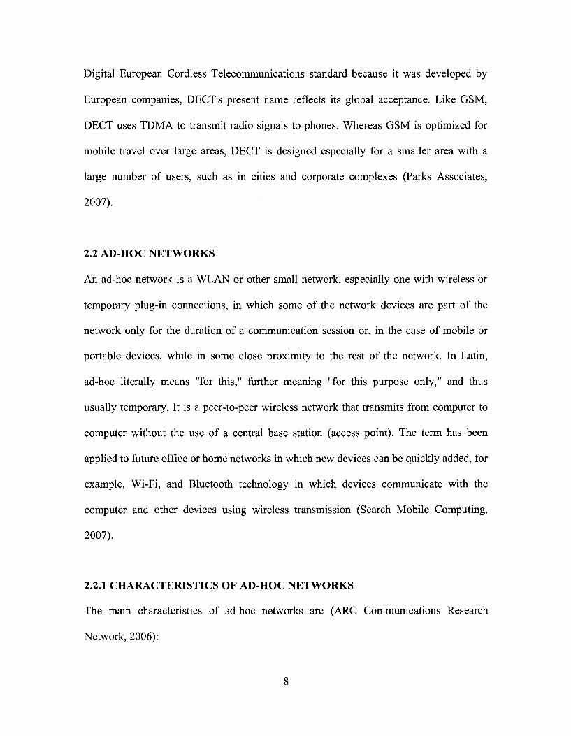
2.2.2 APPLICATIONS OF AD-HOC NETWORKS
The following fields and scenarios could be considered to use ad-hoc networks:
• Construction site: In a construction site, there might be no available
communication infrastructure. Ad-hoc networks could support the on-site
communication and collaboration.
• Emergency salvation: In a man-made or natural disaster, the current
communication infrastructure could be damaged. Ad-hoc networks could act as
the contingency solution for salvation teams (Figure 2.1).
• Sensor networks: Small sensor devices can be attached to animals or other
strategic locations that collectively, to monitor habitats and environmental
conditions.
• Automotive networks: The pre-installed ad-hoc network devices in vehicles can
provide the drivers with information about road conditions, congestions, and
accident-ahead warnings, helping to optimise traffic flow.
• Military applications: Armed forces can create a tactical ad-hoc network in
unfamiliar territory for communications and distribution of situational awareness
information.
2.2.3 SECURITY IN AD-HOC NETWORKS
(1) Link Level Security
In a wireless environment, the links are susceptible to attacks where eavesdropper can
easily spoof the on-going communication. As there is no protection like firewalls or
access control in ad-hoc network, any node can become vulnerable to attacks coming
10

from any direction or from any node. The results of such attacks include spoofing of the
node's identity, tampering with node's credentials, leaking of confidential information or
impersonating node. These types of attacks can easily compromise the basic security
aspects like confidentiality, integrity, and availability and privacy of the node. The
possible solution for link level security could be installing firewalls on each node (Aziz,
2007).
(2) Secure Routing
The routing part of an ad-hoc network is more vulnerable to attacks because each device
acts as a relay. Any tampering with routing information can compromise the whole
network. An attacker can insert rogue information within routing information or
introduce denial-of-service type attack by replaying old logged information. Also,
compromised node can route malicious information to other nodes, which can cause
serious damage. Selecting suitable routing protocols could reduce the potential threaten to
the ad-hoc networks (Vinayakray-Jani, 2002).
2.2.4 QUALITY OF SERVICE (QoS) IN AD-HOC NETWORKS
QoS is a guarantee that the network can satisfy a set of predetermined service
performance constraints for user in terms of the end-to-end delay statistics, available
bandwidth, probability of packet loss, and so on. QoS for a network is measured in terms
of guaranteed amount of data which a network transfers from one place to another in a
given time slot. In ad-hoc networks, the QoS could be measured by the quality of the
delivery of real-time communications such as audio and video. The size of the ad-hoc
network is directly related to the QoS of the network. If the size of the mobile ad-hoc
11

networks (MANETs) is large, it might make the problem of network control extremely
difficult. Communication in MANETs between two participating nodes can be seen as a
complex end-to-end channel that changes routes with time. QoS support in ad-hoc
networks encompasses issues at the application layer, transport layer, network layer,
medium access control (MAC) layer, and physical layer of the network infrastructure
(Computing unplugged, 2007).
2.2.4.1 QoS METRICS
QoS is usually defined as a set of service requirements that needs to be met by the
network while transporting a packet stream from a source to its destination. The network
is expected to guarantee a set of measurable specified service attributes to the user in
terms of end-to-end delay statistics, bandwidth, probability of packet loss, delay variance
(jitter), etc. Energy efficiency and service coverage are two other QoS attributes that are
more specific to wireless ad-hoc networks due to the limited battery source (Prasant,
2004).
The QoS metrics could be concave or additive. Bandwidth is concave in the sense that
end-to-end bandwidth is the minimum of all the links along the path. Delay and delay
jitter are additive. The end-to-end delay (jitter) is the accumulation of all delays (jitters)
of the links along the path. Furthermore, QoS metrics could be defined in terms of one of
the parameters or a set of parameters in varied proportions. Multi-constraint QoS aims to
optimize multiple QoS metrics while provisioning network resources, and is aomplex
problem. It has been proved that if QoS contains at least two additive metrics then the
QoS routing is an NP-complete (NP means non-deterministic polynomial time) problem.
12

Thus heuristic algorithms are usually developed for multi-constraints QoS routing (Li,
2006).
2.2.4.2 ISSUES OF QoS
The following are some of the major issues of QoS (Li, 2006):
• Unpredictable link properties: Wireless media is very unpredictable. Packet collision
is intrinsic to wireless network. Signal propagation faces difficulties such as signal
fading, interference, and multi path cancellation. All these properties make measures
such as bandwidth and delay of a wireless link unpredictable.
• Node mobility: Mobility of the nodes creates a dynamic network topology. Links will
be dynamically formed when two nodes come into the transmission range of each
other and are torn down when they move out of range.
• Limited battery life: Mobile devices generally depend on finite battery sources.
Resource allocation for QoS provisioning must consider residual battery power and
rate of battery consumption corresponding to resource utilization. Thus, all the
techniques for QoS provisioning should be power-aware and power efficient.
• Hidden and exposed terminal problems: In a MAC layer with the traditional carrier
sense multiple access (CSMA) protocol, multi-hop packet relaying introduces the
"hidden terminal" and "exposed terminal" problems. The hidden terminal problem
happens when signals of two nodes, say A and B, that are out of each other's
transmission ranges collide at a common receiver, say node C. With the same nodal
configuration, an exposed terminal problem will result from a scenario where node B
attempts to transmit data (to someone other than A or C) while node C is transmitting
13
to node A. In such a case, node B is exposed to the transmission range of node C and
thus defers its transmission even though it would not interfere with the reception at
node A.
• Route maintenance: The dynamic nature of the network topology and the changing
behavior of the communication medium make the precise maintenance of network
state information very difficult. Thus, the routing algorithms in MANETs have to
operate with inherently imprecise information. Furthermore, in ad-hoc networking
environments, nodes can join or leave at any time. The established routing paths may
be broken even during the process of data transfer. Thus, the need arises for
maintenance and reconstruction of routing paths with minimal overhead and delay.
• QoS-aware routing would require reservation of resources at the routers (intermediate
nodes). However, with the changes in topology the intermediate nodes also change,
and new paths are created. Thus, reservation maintenance with updates in the routing
path becomes cumbersome.
• Security: Security can be considered a QoS attribute. Without adequate security,
unauthorized access and usage may violate QoS negotiations. The nature of
broadcasts in wireless networks potentially results in more security exposure. The
physical medium of communication is inherently insecure, so we need to design
security-aware routing algorithms for MANETs.
14

2.3 ROUTING PROTOCOLS IN AD-HOC NETWORKS
One of the main characteristics of ad-hoc networks is the capability of each node to act as
a router. These routing functions are supported by the routing protocols of the network
layer. As the topology of the network is dynamic, it is a big challenge to design routing
protocols that can cope up with the changing topology. A path in an ad-hoc network
found from host to destination may not remain alive after few moments. To deal with
such situations, researchers have developed routing protocols for ad-hoc networks that
can be classified as proactive, reactive and hybrid (Lee et al., 2007).
(1) Proactive Protocols
Proactive protocols maintain routes to all nodes including nodes to which no packets are
scheduled for, e.g., destination sequenced distanced vector (DSDV) protocol. These
protocols have high overhead in maintaining and updating the whole topology
information periodically. When a packet transmission request is received, the updated
information about routes is searched in the source nodes' routing table and the packet is
transmitted based on the route information available. In case the entry for a route to
destination is not available in the routing table, network wide broadcast is initiated to find
the route.
(2) Reactive Protocols
A reactive protocol, on the contrary, establishes routes on demand. Examples of this
protocol class are ad-hoc on demand distance vector (AODV) and dynamic source
routing (DSR). Due to on-demand route search, these protocols introduce delay in packet
15
delivery. For these protocols whenever a packet has to be sent from source to destination,
route request (RREQ) messages are broadcasted by the source node. The very first of
RREQ message received by destination node prompts it to send the route reply (RREP)
message on the same path it received the RREQ. This process in association with some
other acknowledgement and hello messages allows route discovery for this class of
protocols.
(3) Hybrid Protocols
The third class of ad-hoc routing protocols, the hybrid protocols, combines the best of
proactive and reactive protocols, e.g., Zone Routing Protocol (ZRP). It uses
distance-vectors to determine the best paths to destination networks, and report routing
information only when there is a change in the topology of the network.
2.4 IEEE 802.11 STANDARDS
The IEEE 802.11 standards are widely used for wireless networks. These standards
support communication in two modes: infrastructure mode and ad-hoc mode. 802.11
networks are organized in two ways: in a Basic Service Set (BSS) one station acts as a
master with all the other stations associating to it; this is termed infrastructure mode and
the master station is termed an access point (AP). In BSS mode all communication passes
through the AP. In the second form of networks, there is no master station. This form of
networks is termed an Independent Basic Service Set (IBSS) and is commonly known as
an ad-hoc network (IEEE, 2006).
16

IEEE 802.11 networks were first created in the 2.4 GHz band using protocols defined by
the IEEE 802.11b standard. These specifications include the operating frequencies, MAC
layer characteristics including framing and transmission rates (communication can be
done at various rates). Later the IEEE 802.11a standard defined operation in the 5 GHz
band, including different signaling mechanisms and higher transmission rates. Still later
the 802.1 lg standard was defined to enable the use of 802.1 la signaling and transmission
mechanisms in the 2.4 GHz band in such a way as to be backwards compatible with
802.1 lb networks (IEEE, 2006).
IEEE 802.11 standards have provided some basic security mechanisms to make ad-hoc
networks less of a potential threat. For example, 802.11 access points (or sets of access
points) can be configured with a service set identifier (SSID). Additional security is
provided through the 802.11 specifications through the Wired Equivalent Privacy (WEP)
algorithm. WEP provides 802.11 with authentication and encryption services. The WEP
algorithm defines the use of a 40-bit secret key for authentication and encryption and
many IEEE 802.11 implementations also allow 104-bit secret keys. This algorithm
provides mostly protection against eavesdropping and physical security attributes
comparable to a wired network (IEEE, 2006).
Other than the above protocol standards, the other important standard to be aware of is
802.1 le. This defines protocols for deploying multi-media applications such as streaming
video and voice over IP (VoIP) in an 802.11 network. The 802.1 le has a precursor
17

specification termed Wireless Multimedia Extensions (WME) (and now Wi-Fi
Multimedia (WMM)) that has been defined by an industry group as a subset of 802.1 le
that can be implemented to enable multi-media applications while waiting for the final
ratification of 802.1 le. The most important thing to understand about 802.1 le and
WME/WMM is that they enable prioritized traffic use of a wireless network through
Quality of Service (QoS) protocols and enhanced media access protocols. Proper
implementation of these protocols enable high speed bursting of data and prioritized
traffic flow (IEEE, 2006).
2.5 NETWORK SIMULATION
Network simulation is a technique where a program manipulates simulated entities, such
as hosts and routers, in order to determine their behavior under various conditions. A
simulator is a device, computer program or system used during software verification,
which behaves or operates like a given system when provided with a set of controlled
inputs (IEEE, 2006). A key feature of network design is the estimation of the
performance of a proposed network design. In the case of realistic network topologies
and network applications, performance estimation is a difficult problem. As a result, a
number of powerful simulators have been developed that are capable of attacking these
problems. Three of the well-known simulators are Ns2, OPNET, and GloMoSim.
18

(1) NS2
Ns2 is a free and open-source network simulator. It is a discrete event simulator targeted
at networking research. Ns2 provides substantial support for simulation of TCP, routing,
and multicast protocols over wired and wireless (local and satellite) networks. Ns2 covers
a very large number of applications, protocols, network types, network elements and
traffic models. Ns2 is based on two languages: an object oriented simulator, written in
C++, and a OTcl (an object oriented extension of Tel) interpreter, used to execute user's
command scripts (USC, 2005).
Characteristics of NS2:
• The compiled C++ hierarchy allows it to achieve efficiency in the simulation and
faster execution time.
• Ns2 is a discrete event simulator, where the advance of time depends on the timing of
events which are maintained by a scheduler.
• Tel allows a fast development, provides a graphic interface, is compatible with many
platforms, and is flexible for integration (USC, 2005).
Because of its availability and the above characteristics, Ns2 is used in this research.
(2) OPNET
OPNET is the industry's leading simulator specialized in network research and
development (OPNET technologies, 2007). It allows users to design and study
communication networks, devices, protocols, and applications with great flexibility. It
provides a graphical editor interface to build models for various network entities from
19

physical layer modulator to application processes. All the components are modeled in an
object-oriented approach which gives intuitive easy mapping to real systems. OPNET
simulations are usually created and configured using a mix of graphical ditors,
state-diagrams and C++. The OPNET's discrete event engine for network simulations is
the fastest and most scalable commercially available solution. It usually takes just a few
minutes to complete simulations of most lab experiments (OPNET technologies, 2007).
(3) GloMoSim
GloMoSim is a scalable simulation environment for wireless and wired network systems.
It is being designed using the parallel discrete-event simulation capability provided by
Parsec. GloMoSim currently supports protocols for a purely wireless network.
GloMoSim allows the simulation of wired and wireless networks, and it is configured
through a configuration file and provides a reasonable number of readily available
protocols, radio layers, etc. (UCLA Parallel Computing Laboratory, 2007).
2.6 DATA REPLICATION AND CLUSTERING IN AD-HOC NETWORKS
2.6.1 DATA REPLICATION IN AD-HOC NETWORKS
In ad-hoc networks, since the nodes move freely, network divisions happen frequently,
which leads to lower data accessibility than that in wired networks. Therefore, an
efficient method that can backup the important data in ad-hoc networks is needed (Jiang
et al., 1999). In order to solve this problem, effective replica allocation can be used.
Several replica allocation methods have been proposed, such as Static Access Frequency
20

(SAF) method, Dynamic Access Frequency and Neighborhood (DAFN) method, and
Dynamic Connectivity based Grouping (DCG) method (Hara, 2001).
D; D< D-
/
D-Do
I>5 ' • A f c ^
DA
D* D ; ,
/ ^.M,: '{\r /
/
i>3 i>:
y
Figure 2.2 DCG Method (Hara, 2001)
The DCG method extended the SAF and DAFN methods; it divides the nodes into larger
groups based on biconnected components (Aho et al , 1974), and checks the replicas
between groups. Figure 2.2 shows the detailed method: First, at the relocation period,
each node broadcasts its identifier and information on data item access frequencies.
Second, the algorithm separate the nodes into groups based on biconnected components.
Third, each group calculates the sum of access frequencies of each data item. Fourth, in
the order of the access frequencies of the group, replicas of the original data in other
groups are allocated to the node which has higher access frequency of the data until
memory space of all nodes in the group becomes full. Finally, if there is free memory
space left in the group, replicas of the original data that in this group are allocated in the
order of access frequencies until the memory space is full. The DCG method shares
replicas in larger groups, so the network has higher stability. However, it uses lot of time
21

to exchange information among nodes and calculate access frequencies, so the overhead
and traffic are higher than other replication methods (Hara, 2001).
2.6.2 CLUSTERING IN AD-HOC NETWORKS
Large number of nodes in the same network could reduce the efficiency of the network.
Therefore, in order to improve the scalability of the network, it should be divided into
clusters, with every cluster having no more than 50 nodes (Xu and Hischke, 2003). The
clusters in the MANETs are groups of mobile nodes. These nodes move within or among
clusters with some special rules. Furthermore, nodes in the same cluster are assigned
different status and functions, such as cluster heads, cluster member, and gateway. The
current clustering methods in MANETs could be divided into the following categories:
(1) DS-based clustering
This clustering scheme tries to find a Dominating Set (DS) or Connected Dominating Set
(CDS) to reduce the number of nodes participating in route search or routing table
maintenance. In this scheme, routing is done through DS or CDS (Yu and Chong, 2005).
(2) Low-maintenance clustering
This clustering scheme provides a cluster infrastructure for upper layer applications with
little cluster maintenance cost (Yu and Chong, 2005). It tries to eliminate the control
overhead for clustering by constructing and maintaining cluster architecture based on data
traffic forwarding (Kwon et al., 2003). Examples of low-maintenance clustering are: LCC
22
(Least Cluster Change) (Chiang and Gerla, 1997), LIC (Lowest ID Clustering)
(Ephremides et al., 1987).
(3) Mobility-aware clustering
This clustering scheme utilizes the mobility behavior of mobile nodes for cluster
construction and maintenance, and assigns mobile nodes with low relative speed to the
same cluster to tighten the connection within the cluster. Therefore, the re-affiliation and
re-clustering rate can be reduced (Yu and Chong, 2005).
(4) Energy-efficient clustering
This clustering scheme avoids unnecessary energy consumption and balances energy
consumption for mobile nodes in order to prolong the lifetime of mobile nodes and the
whole network (Yu and Chong, 2005). Energy consumption of mobile nodes could lead
to network partition and communication interruption. Therefore, it is important to balance
the energy consumption among the whole network.
(5) Load-balancing clustering
This clustering scheme attempts to limit the number of mobile nodes in each cluster to a
defined range in order to keep all clusters with the similar size (Yu and Chong, 2005).
This method has upper and lower limits on the number of mobile nodes that a cluster can
deal with. Thus, the network loads can be more averagely distributed in each cluster.
23

(6) Combined-metrics-based clustering
This cluster scheme considers multiple metrics, such as, cluster size, mobility speed, and
battery energy in cluster configuration, and adjusts their weighting factors for different
application scenarios (Yu and Chong, 2005). This method aims to elect the most suitable
cluster head in a local area, and do not give preference to mobile nodes with certain
attributes, such as lowest ID or highest node degree. Example of combined-metrics-based
is: On-Demand WCA (Weighted Cluster Algorithm) (Chatterjee et al., 2000).
2.6.3 CLUSTER BASED REPLICA ALLOCATION (CBRA)
As reviewed in Section 2.6.1, the DCG method divides the nodes into larger groups based
on biconnected components (Aho et al., 1974), and checks the replicas between groups.
However, in real ad-hoc networks, all nodes move randomly, and it is possible that more
than one node disappear at the same time. If these nodes were in important positions in
the same group (For example, node 8, 9, 10, 11 in group II in Figure 2.3), then the new
partitions will happen.
Efficient clustering and routing protocols are important parts of the design of an ad-hoc
network (Macker, 1997). Clustering saves resources which may result from transmission
collisions. Clustering also improves routing performance through cluster heads and
gateway clients; therefore restricting the routing events to a set of clients. In addition, the
cluster structure makes an ad-hoc network appears smaller and stable from the point of
view of each mobile client because only clients belonging to the same cluster need to
24

update information. In order to avoid the problem in Figure 2.3, Mahboob (2005)
introduced a new replication method, CBRA, based on clustering.
Group 1
Figure 2.3 New Partitions in DCG Method (Mahboob, 2005)
In Section 2.6.2, many different cluster schemes were reviewed. All of these schemes
have their overhead and associated costs. In order to avoid the partitions within clusters
and keep message overhead under control, a hybrid grouping approach was selected
combining Least Cluster Change (LCC) (Chiang and Gerla, 1997) and Lowest ID
Clustering (LIC) (Ephremides et al , 1987) to form the clusters because of the simplicity
of operation and low cluster maintenance cost of CBRA protocol.
Comparing with other methods, CBRA makes the data replication among clusters. For
example, in Figure 2.4: Firstly, the algorithm divides the whole network into clusters, and
selects one node in each cluster as the cluster head; Secondly, at the relocation period,
each cluster member sends its identifier and information on data item access frequencies
to its cluster head; Thirdly, each cluster head calculates the sum of access frequencies of
each data item; Fourthly, in the order of the access frequencies of the cluster, replicas of
25

the original data in other clusters are allocated to the node which has higher access
frequency of the data until memory space of all nodes in the cluster becomes full; Finally,
if there is free memory space left in the cluster, replicas of the original data that in this
cluster are allocated in the order of access frequencies until the memory space is full
(Mahboob, 2005).
Figure 2.4 CBRA Algorithm (Mahboob, 2005)
With this method, the network in Figure 2.3 could be divided into three clusters (Figure
2.5). All data items are replicated among these three clusters, which limited the effects of
new partitioning. For example, if the new partition happens between cluster II and cluster
III, the whole network will not be disturbed and the data accessibility will not decrease,
because each cluster has the replication of other clusters.
26
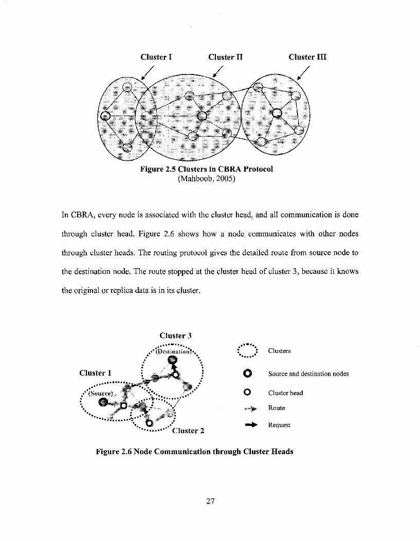
Cluster I Cluster II Cluster III
Figure 2.5 Clusters in CBRA Protocol (Mahboob, 2005)
In CBRA, every node is associated with the cluster head, and all communication is done
through cluster head. Figure 2.6 shows how a node communicates with other nodes
through cluster heads. The routing protocol gives the detailed route from source node to
the destination node. The route stopped at the cluster head of cluster 3, because it knows
the original or replica data is in its cluster.
Cluster 3
,•* (Destination)*,
V* /.»•
***•••'• * C l u s t e r 2
* Clusters
fjl Source and destination nodes
O Cluster head
Route
Request
Figure 2.6 Node Communication through Cluster Heads
27
Start
Data access request
Send request to cluster head
Yes
Send request to other cluster heads
Discard request
No
End
Send request to the node which has the data
The destination node sends reply to the source node
Data transferring
End
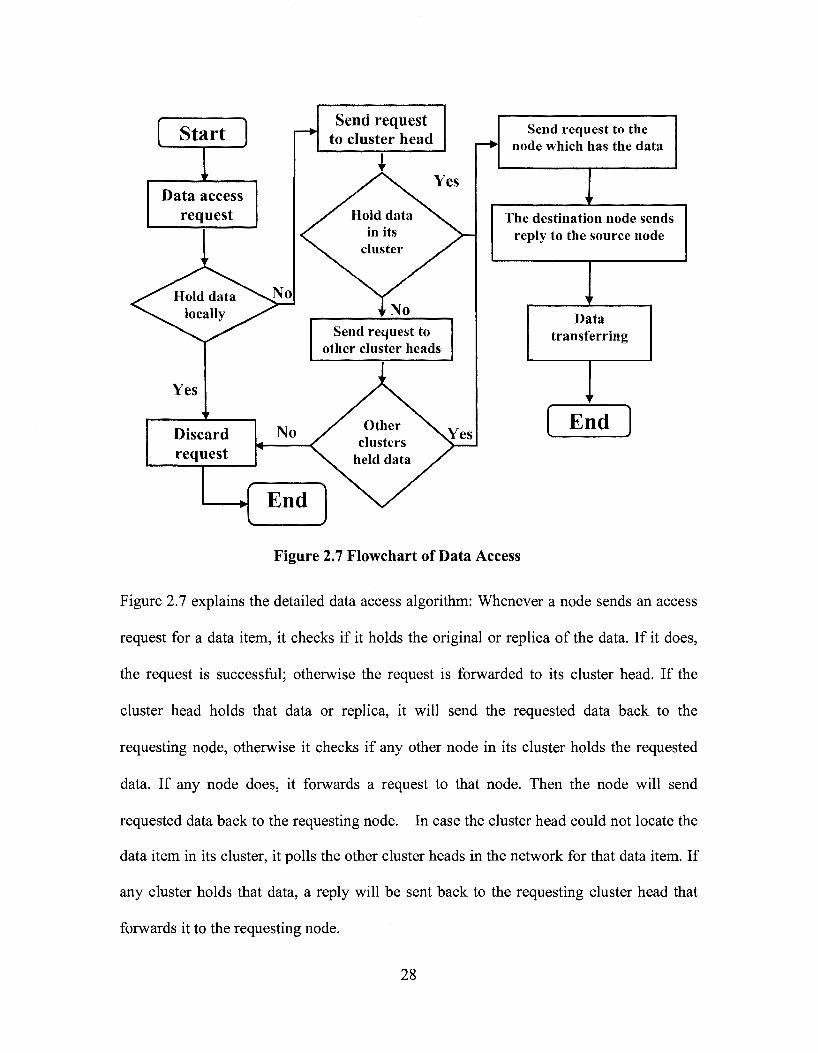
Figure 2.7 Flowchart of Data Access
Figure 2.7 explains the detailed data access algorithm: Whenever a node sends an access
request for a data item, it checks if it holds the original or replica of the data. If it does,
the request is successful; otherwise the request is forwarded to its cluster head. If the
cluster head holds that data or replica, it will send the requested data back to the
requesting node, otherwise it checks if any other node in its cluster holds the requested
data. If any node does, it forwards a request to that node. Then the node will send
requested data back to the requesting node. In case the cluster head could not locate the
data item in its cluster, it polls the other cluster heads in the network for that data item. If
any cluster holds that data, a reply will be sent back to the requesting cluster head that
forwards it to the requesting node.
28

2.7 MOBILE AD-HOC TEST-BEDS
A test-bed is a platform on which an assortment of experimental tools and products may
be deployed and allowed to interact in real-time (Buchegger et al., 2004). The following
are examples of ad-hoc wireless network test-beds.
2.7.1 WIRELESS AD-HOC NETWORK TEST-BED IN DUBLIN
This test-bed covers the centre of Dublin along a 2 km route. This area is seeded with a
number of custom-build wireless-enabled embedded PCs. These PCs are 3x3x6 inch
containers that accommodate a stack of PC/104 boards, WiFi PCMCIA cards, and a set of
antennae. The embedded PCs are hosted in apartments and shops, on traffic lights, and in
phone kiosks along the route to provide a minimum level of connectivity. The test-bed
can be further populated through the introduction of mobile nodes such as laptops, PDAs,
and other mobile devices with wireless connectivity. This ability to be configured in
various ways and to be populated with a variable number of nodes enables researchers to
develop and investigate protocols and applications that are specific to the area of ad hoc
networking (DSG, 2006).
2.7.2 AD-HOC NETWORK TEST-BED AT UNIVERSITY OF COLORADO
The test-bed at the University of Colorado is designed to facilitate experiments based on
wireless ad-hoc networks including radios mounted at fixed sites (Figure 2.8 (c)), on
ground vehicles (Figure 2.8 (b)), and in small Unmanned Aerial Vehicles (UAVs) (Figure
2.8 (a)). Jadhav et al., (2005) built a special device named Mesh Network Radio (MNR)
29

Components (Figure 2.8 (d)) inside the above positions. Furthermore, laptop computers,
PDAs, and special-purpose ad-hoc radios running the Dynamic Source Routing (DSR)
protocol over IEEE 802.1 lb serve as nodes in this test bed (Jadhav et al., 2005).
(a) Unmanned Aerial Vehicle (UAV) (b) Ground Mobile
(c) Fixed (d) Mesh network radio (MNR) components
Figure 2.8 Heterogeneous Ad-Hoc Radio Nodes of Colorado (Jadhav et al., 2005)
2.7.3 WIRELESS SHUTTLE BUS PROJECT AT JOHNS HOPKINS
UNIVERSITY (JHU)
This test-bed provides the JHU Security Department with the ability to track the speed
and location of the escort shuttles in real-time. They used Wave Relay Mobile Router to
connect the shuttle buses as an ad-hoc network. In order to locate the position of each bus,
they integrate GPS receivers with the system. The scenograph of the shuttle bus system is
shown in Figure 2.9. This project provides JHU students with wireless Internet access
30

while traveling on escort shuttles, and allows students to track current shuttle positions
online to determine pickup times. It provides a completely mobile test-bed for evaluating
the performance of MANET routing protocols (JHU, 2006).
Wave Relay Router
GPS Receiver
lahcrn.t I'm) „ . I — • p-lX/.hmo
*,&--5***--.-. ls-5- ;•-•---.:••--•• *.^-^~T»rtffira?T^ - ^ - s ..•• • • ' " " " " " , * * k * x * ^ p 4 i * .'• g "
Figure 2.9 Shuttle Bus Project in JHU (JHU, 2005)
2.7.4 WIRELESS DATA COLLECTION ON CONSTRUCTION SITES
This test-bed provides a system named Wireless Network Cells (WNC) to use wireless
network covering the whole site (Figure 2.10). The user on-site is equipped with a
touch-screen Windows CE tablet PC, which enables the user to gain access to the
server-based database over wireless network.
a a raH*Tf .»,,
Wireless Network Cell (WNC)
Site Office Rig "J."!
Figure 2.10 Wireless Network Cell Configuration (Ward et al., 2005)
Each WNC provides coverage to a certain area of the site allowing roaming users to
connect to the server-based database. Figures 2.11(a-d) show different types of WNC
connecting with the site office (Ward et al , 2004).
31

(c) Site Office (d) Fixed WNC Figure 2.11 Different Wireless Network Cell (WNC)
(Ward et al., 2005)
2.7.5 MOBILE AD-HOC SPACE FOR COLLABORATION TO SUPPORT
DISASTER RELIEF EFFORTS
This test-bed provides a reliable, transparent, and portable Mobile Ad-hoc Space for
Collaboration (MASC) based on a short range wireless communication platform
(Aldunate et al., 2006). MASC is a distributed system that provides several collaboration
capabilities, highly available memory services in a transparent way, and adequate
performance to distributed collaborative applications running on wearable or handheld
computers. The capabilities of MASC also support the tasks of civil engineers working in
disaster areas, through distributed retrieving/updating of information and the use of
collaborative software tools such as CAD, GIS and structural analysis tools. The
32

collaborative Infrastructure Status System was implemented on MASC and was coded
with Visual C++ for Windows and Windows CE. Figure 2.12 shows the system built
using the services provided by MASC, which presents the stability of the infrastructure in
the disaster area as assessed by the civil engineers in a first response team. Figure 2.13
shows three search and rescue exercises by using the MASC system (Aldunate et al.,
Figure 2.12 Shared Views for a First Response Team in a Simulated Disaster Area (Aldunate et al., 2006)
Figure 2.13 Search and Rescue Exercise Supported by MASC System (Aldunate et al , 2006)
2.8 SUMMARY AND CONCLUSIONS
In this chapter, the literature about the available types of wireless networks, related issues,
and their applications has been reviewed. Some of these wireless networks, such as
33

CDMA, are relatively costly and should depend on the service provider; Some wireless
networks, such as DECT, have limited coverage; Some wireless networks need some type
of infrastructure (e.g., signal tower, routers, etc.). If the available infrastructure is
damaged because of natural or man-made disasters, all the communications on-site will
stop, which will lead to extra losses and, in some cases, additional casualties.
Consequently, a technique which does not need any infrastructures, and which is
economical and efficient is needed. Furthermore, several research projects which
considered the usage of wireless networks to support on-site communications have been
reviewed. However, the research about the efficient usage of ad-hoc networking in
engineering applications is still limited. On the other hand, research about new protocols
aiming to improve the ad-hoc network performance is progressing using several
clustering and replication techniques. However, these protocols need careful testing from
the point-of-view of the engineering applications. Finally, these wireless networks have
some disadvantages that may not be suitable for some special scenarios, such as
construction site, emergency salvation, and military applications.
34
CHAPTER 3 PROPOSED APPROACH
3.1 INTRODUCTION
Efficient collaboration among team members working on site, such as inspection teams
and search and rescue teams after a disaster, is important to realize the intended tasks.
Real-time communication is necessary for those on-site workers to enhance their
collaborative efforts. As introduced in Chapter 2, several technologies are used on site.
However, these technologies have some disadvantages that may affect the work. For
example, satellite telecommunications is relatively costly, DECT has limited coverage,
GSM, GPRS, and CDMA depend on the service provider, and WLAN users are bounded
to certain locations (Beyh and Kagioglou, 2004). Furthermore, all of the above
technologies need some type of infrastructure (e.g., wiring, routers, etc.). If the available
infrastructure is damaged because of natural or man-made disasters, all the
communications on-site will stop, which will lead to extra losses and, in some cases,
additional casualties (Yang and Hammad, 2007). Consequently, a technique which does
not need any infrastructures, and which is economical and efficient is needed. Ad-hoc
networking is an attractive solution for this problem because it allows on-site workers
using portable devices to communicate and keep in touch with each other when they are
performing their tasks (Kuladinithi et al., 2003; 2004). Minimal configuration and quick
deployment make ad-hoc networks suitable for construction sites or emergency situations
(Chlamtac et al., 2003).
In Chapter 3, we will investigate the following problems of deploying ad-hoc wireless
networks for supporting on-site communication: (1) Defining the basic modes of
35

communication which are common in field applications and providing a platform for
testing several wireless ad-hoc communication modes under different conditions; (2)
Testing the CBRA protocol based on clustering to improve data accessibility and a
simulation algorithm based on CBRA. As explained in Section 2.2.4, QoS of MANETs
includes several issues, such as node mobility, route maintenance, limited battery life, etc.
In this research, the main focus is on testing the QoS properties of throughput and data
accessibility.
3.2 PROPOSED SYSTEM FOR TESTING AD-HOC WIRELESS
COMMUNICATIONS
Efficient communication and collaboration requires that team members should be able to
know about the location of each other, exchange information, communicate with each
other using different communication modes, and check the performance of the network to
decide what kind of communication is possible and efficient. Although most wireless
protocol testing can be done with software simulations for the initial design and
estimation of results, they do not realistically duplicate the physical layer. A software
simulator also ignores interlayer communication, which is integral to the effectiveness of
these protocols. This makes hardware testing critical (Sanghani, 2003). Therefore, in
order to test several on-site communication modes using mobile devices (e.g., laptops),
we developed a prototype system called Ad-hoc Messenger which allows users to
communicate with each other by using an ad-hoc wireless network. This system (Figure
3.1) is based on IEEE 802.11 standards, and it supports TCP/IP (IP v4 and v6). It uses
36
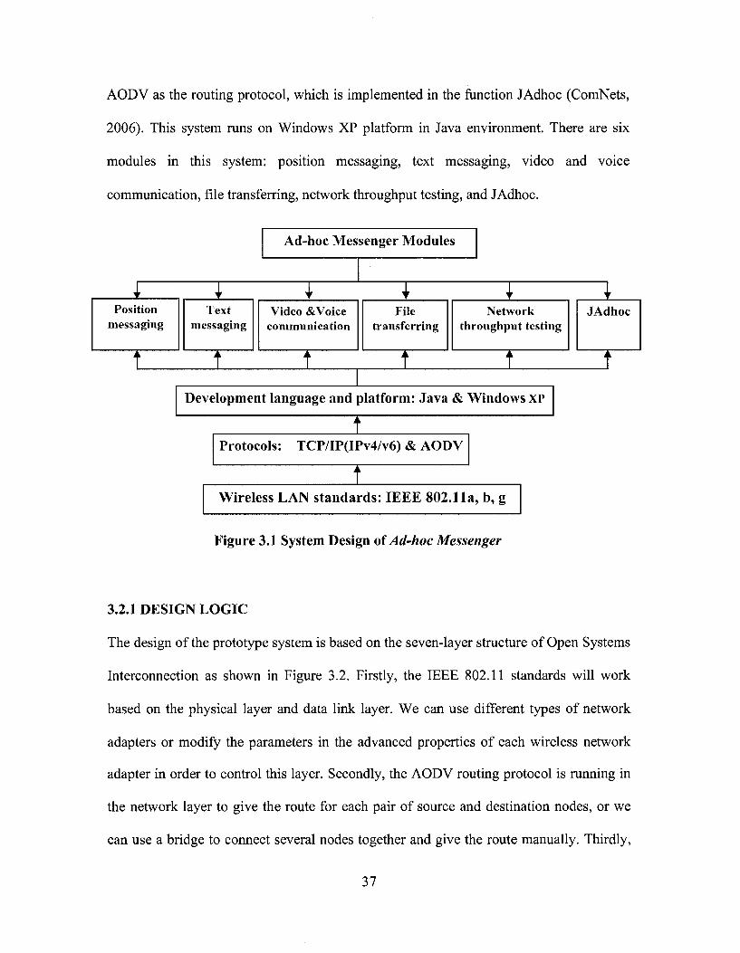
AODV as the routing protocol, which is implemented in the function JAdhoc (ComNets,
2006). This system runs on Windows XP platform in Java environment. There are six
modules in this system: position messaging, text messaging, video and voice
communication, file transferring, network throughput testing, and JAdhoc.
Ad-hoc Messenger Modules
Position messaging
Text messaging
Video & Voice communication
File transferring
Network throughput testing
JAdhoc
Development language and platform: Java & Windows XP
Protocols: TCP/IP(IPv4/v6) & AODV
Wireless LAN standards: IEEE 802.11a, b, g
Figure 3.1 System Design of Ad-hoc Messenger
3.2.1 DESIGN LOGIC
The design of the prototype system is based on the seven-layer structure of Open Systems
Interconnection as shown in Figure 3.2. Firstly, the IEEE 802.11 standards will work
based on the physical layer and data link layer. We can use different types of network
adapters or modify the parameters in the advanced properties of each wireless network
adapter in order to control this layer. Secondly, the AODV routing protocol is running in
the network layer to give the route for each pair of source and destination nodes, or we
can use a bridge to connect several nodes together and give the route manually. Thirdly,
37
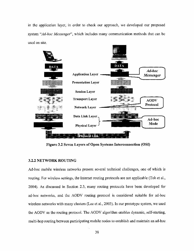
in the application layer, in order to check our approach, we developed our proposed
system "Ad-hoc Messenger", which includes many communication methods that can be
used on site.
Application Layer
Presentation Layer
Session Layer
Transport Layer
Network Layer —
Ad-hoc Messenger
Data Link Layer
Physical Layer } •*••>•. *• -»*«;
-r" Ad-hoc Mode
Physical Link
Figure 3.2 Seven Layers of Open Systems Interconnection (OSI)
3.2.2 NETWORK ROUTING
Ad-hoc mobile wireless networks present several technical challenges, one of which is
routing. For wireless settings, the Internet routing protocols are not applicable (Toh et al.,
2004). As discussed in Section 2.3, many routing protocols have been developed for
ad-hoc networks, and the AODV routing protocol is considered suitable for ad-hoc
wireless networks with many clusters (Lee et al , 2003). In our prototype system, we used
the AODV as the routing protocol. The AODV algorithm enables dynamic, self-starting,
multi-hop routing between participating mobile nodes to establish and maintain an ad-hoc
38

network. It allows mobile nodes to obtain routes quickly for new destinations, and does
not require nodes to maintain routes to destinations that are not in active communication.
In addition, it allows mobile nodes to respond to link breakages and changes in network
topology in a timely manner (Charles et al., 2003).
Start
Origin node requests a route to a destination node
Send RREQ to all neighbours and wait
for RREP
Intermediate node receives RREQ and
set up a reverse path
Send RREP to origin node
Generate a RREP to both origin node and
destination node
Send RERR to all origin nodes
Yes
All nodes in the active route send broadcasting
HELLO message
Origin node sends RREP-ACK to
destination node and set up the bi-directional path
Figure 3.3 Algorithm of JAdhoc Function (Adapted from ComNets, 2006)
39

In our system - Ad-hoc Messenger, we combined a function named JAdhoc into our
system. JAdhoc is a function developed at Bremen University in Germany (ComNets,
2006) as an implementation of the AODV routing protocol. In our system, this function
works on the network layer. When a node generates the access request, JAdhoc gives the
detailed route from the source node to the destination node in the ad-hoc network. The
basic algorithm of JAdhoc is explained in the following paragraph (Figure 3.3).
When a node needs a route to a destination node, it initiates a route discovery process.
The route manager class involves a network wide flood of RREQ targeting the
destination node and waiting for a RREP. If an intermediate node receives the RREQ, it
first sets up a reverse path to the origin node using the previous hop of the RREQ as the
next node hop on the reverse path. If the intermediate node has a valid route to the
destination node, it will generate a RREP to the origin node and a gratuitous RREP to the
destination node; else the RREQ is rebroadcast. Meanwhile, the duplicate copies of
RREQ received at any node are discarded (duplicate copies are identified by RREQ ID
maintained for the origin node).
When the destination receives a RREQ, it also generates a RREP. The RREP is routed
back to the origin node via the reverse path. As the RREP proceeds towards the origin
node, a forward path to the destination is established. The origin node can send
RREP-ACK to the destination upon receiving the RREP in order to assure the reliability
of the bi-directional path. At the same time, each node, which has active routes, starts
multicasting a special RREP message with a Time To Live (TTL) field set to 1. This is
40

called a HELLO message. The link layer connectivity to the immediate neighbors can be
detected using the link layer information or listening to HELLO messages. When a node
detects the link failure, a route error (RERR) is sent back via separately maintained
precursor lists to all origin nodes that are affected by the failed link. When the origin
node receives the RERR, it can start a route discovery process again. During the process,
unused routes in the routing table are expired using a timer-based technique (ComNets,
2006).
3.2.3 COMMUNICATION FUNCTIONS IN AD-HOC MESSENGER
The following information are wirelessly transmitted in Ad-hoc Messenger (Figure 3.1):
(1) The locations of team members within a 2D or 3D model of the site are tracked using
Global Positioning System (GPS) receivers or other tracking methods and communicated
to other members of the team; (2) The team members can exchange information in
different formats (text messages, voice, and video); (3) In order to share files, the users
can transmit files to each other; and (4) A user can test the throughput of the network, and
then decide which communication method he/she should use. This testing is important
because users may not know how far their colleagues are or if they can receive a large file
or communicate with text, voice, or video. Our system has a function to test the
throughput of the network between two devices using the average data transmission
speed of the current connection. Then, based on the measured throughput, the system
suggests a suitable combination of communication modes (text, voice, and video). The
text messaging function is a local area broadcasting system. Text messaging is preferable
when the distance between clients is long or their mobile devices do not have enough
41
battery. In other cases, the users can select video and/or voice communications depending
on the conditions (battery life, distance, etc.). In case a client disconnected from the
network because of mobility, the system will continuously check for other nodes and
re-establish the connection if a node became within range.
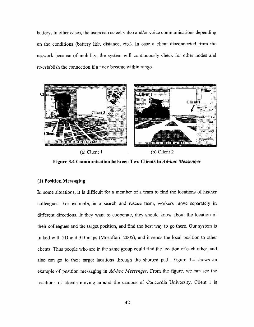
(a) Client 1 (b) Client 2
Figure 3.4 Communication between Two Clients in Ad-hoc Messenger
(1) Position Messaging
In some situations, it is difficult for a member of a team to find the locations of his/her
colleagues. For example, in a search and rescue team, workers move separately in
different directions. If they want to cooperate, they should know about the location of
their colleagues and the target position, and find the best way to go there. Our system is
linked with 2D and 3D maps (Mozaffari, 2005), and it sends the local position to other
clients. Thus people who are in the same group could find the location of each other, and
also can go to their target lacations through the shortest path. Figure 3.4 shows an
example of position messaging in Ad-hoc Messenger. From the figure, we can see the
locations of clients moving around the campus of Concordia University. Client 1 is
42

playing the role of the team leader, so he/she can see all clients from a high point of view.
This function is very useful in emergency situations, such as the shooting accident at
Dawson College, Montreal, September 2006. If the police officers have had a system
with similar functionalities, they might have easily found the cafeteria inside Dawson
College where the crime happened, and less people would have been hurt.
(a) Client 1 (b) Client 2
Figure 3.5 Text Messaging in Ad-hoc Messenger
(2) Text Messaging
The text messaging function of the system is a local area broadcasting system, which
means members of the same group can see the message on the messaging panel. Text
messaging is preferable over voice or video modes of communication when the distance
between clients is very long or their mobile devices do not have enough battery. Figure
3.5 shows an example of two clients using text messaging.
43

(3) Video and Voice Communication
In construction sites, emergency scenes, or battlefields, people need to talk with each
other and sometimes they need video communication. The users can select the suitable
mode of communication depending on the situation: video with voice, or only voice
communication. If the devices have enough battery, and the clients are within a suitable
communication distance, the system can support a good communication quality of
service. Figure 3.4 shows an example of two clients using video and voice
communication.
Jerry> Just log in Jerry> Hi, Antony, Antony> Hi, Jerry, Levesque Blvd.
where ace you I am ualklna o
100?
•i Guy stcee
^ • M M H S a j f ^ H B
ijMjg|gjgj]ja l^^^^tej jT '^" i f f l i iJ t |
^ffi^^^_^ttg^
*5fe3 . ^w^^^^^ ^twflgft '^J&||£|||||9|B
Bilk ^SSl *^j^^ l s | | |
11311
•^•i k?
2?«ii3 B i ?
Stkl
I?: llllpp*' P^^IggHijj
"•«iSlite,.,1*Sii • f c ^ B I H f c i f c ^
Figure 3.6 File Transferring in Ad-hoc Messenger
(4) File Transferring
Sharing files is an important function in field operations. Team members need to send
reports to the team leader, receive commands from the leader, or send images or video
44
clips to each other. Our system can support any file formats, from a small text file, to a
large video file of several gigabytes. Figure 3.6 shows an example of sending a file to
another client. The user can see the size of the file, the percentage of the transmitted part,
and lapsed time. If the connection is cut due to any reason, the user can restart the
transmission, and the system can find where the file was stopped, and continue to
transmit the file from that point.
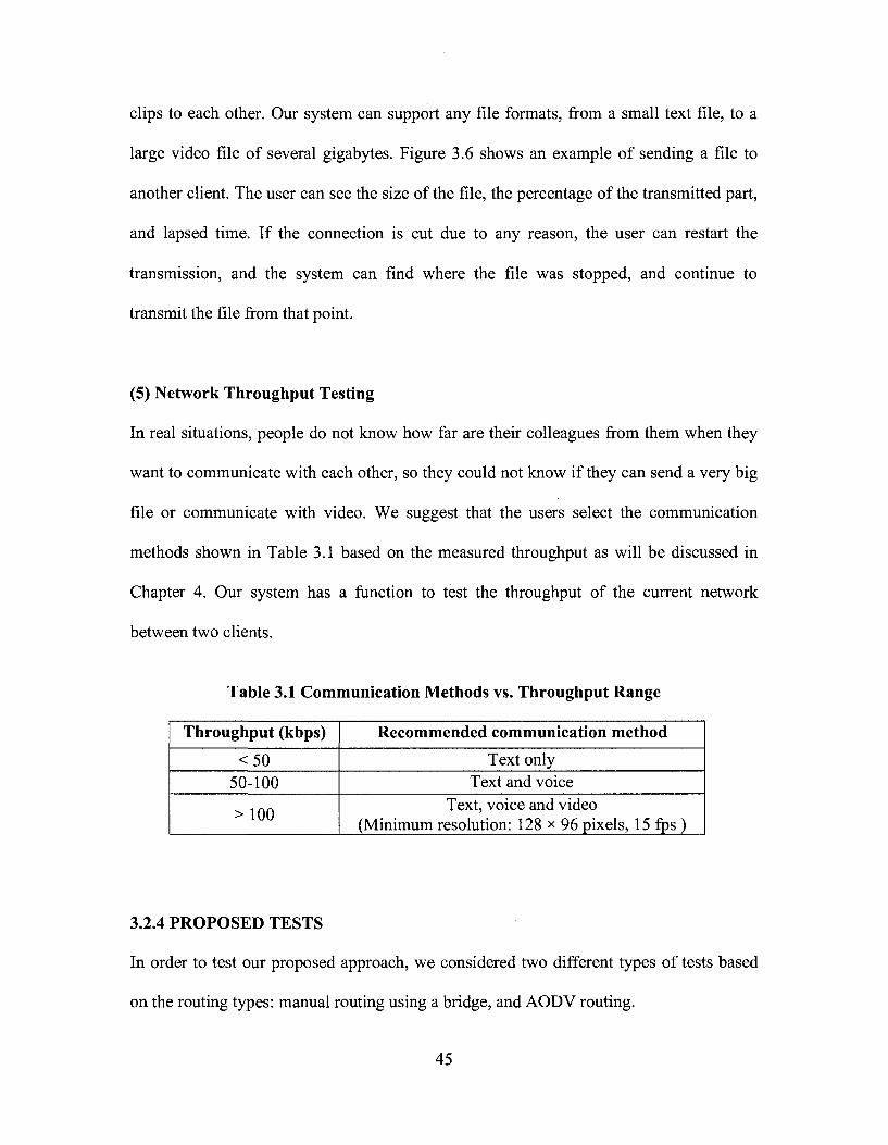
(5) Network Throughput Testing
In real situations, people do not know how far are their colleagues from them when they
want to communicate with each other, so they could not know if they can send a very big
file or communicate with video. We suggest that the users select the communication
methods shown in Table 3.1 based on the measured throughput as will be discussed in
Chapter 4. Our system has a function to test the throughput of the current network
between two clients.
Table 3.1 Communication Methods vs. Throughput Range
Throughput (kbps)
<50 50-100
> 100
Recommended communication method
Text only Text and voice
Text, voice and video (Minimum resolution: 128 x 96 pixels, 15 fps )
3.2.4 PROPOSED TESTS
In order to test our proposed approach, we considered two different types of tests based
on the routing types: manual routing using a bridge, and AODV routing.
45

3.2.4.1 TEST WITH A BRIDGE
The first test is using a bridge as the connection node between the source and destination
nodes. In this test, the bridge node should be a powerful portable device that has at least
two wireless network adapters. Furthermore, the communication route is already set up
manually by combining these two wireless adapters together as one bridge. Figure 3.7
shows how nodes communicate with each other through the bridge node. In this case, the
roles of the bridge and other nodes could not be exchanged, and all communication
between two domains is done through the bridge node (The detailed configuration is
explained in Appendix B).
Using a bridge has some disadvantages: (1) The intermediate node (the bridge) should be
configured in a specific way with two IP addresses, and if it is shut down, the whole
network will crash; and (2) The combination of two wireless adapters is difficult because
of the incompatibility of different types.
Bridge with two combined
Figure 3.7 Communications through a Bridge
3.2.4.2 TEST WITH AODV ROUTING PROTOCOL
The second test is using AODV routing protocol to solve the routing problems. In this
test, the nodes are self-organized, and the only requirement for the mobile nodes is to
46
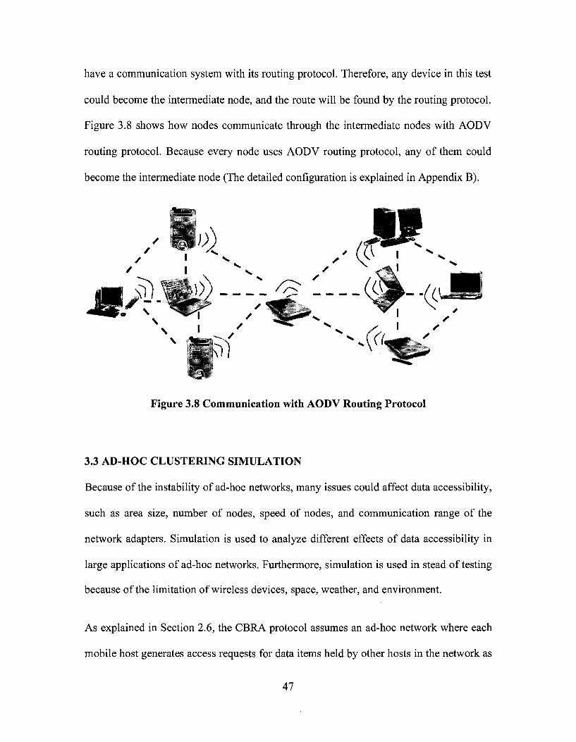
have a communication system with its routing protocol. Therefore, any device in this test
could become the intermediate node, and the route will be found by the routing protocol.
Figure 3.8 shows how nodes communicate through the intermediate nodes with AODV
routing protocol. Because every node uses AODV routing protocol, any of them could
become the intermediate node (The detailed configuration is explained in Appendix B).
Figure 3.8 Communication with AODV Routing Protocol
3.3 AD-HOC CLUSTERING SIMULATION
Because of the instability of ad-hoc networks, many issues could affect data accessibility,
such as area size, number of nodes, speed of nodes, and communication range of the
network adapters. Simulation is used to analyze different effects of data accessibility in
large applications of ad-hoc networks. Furthermore, simulation is used in stead of testing
because of the limitation of wireless devices, space, weather, and environment.
As explained in Section 2.6, the CBRA protocol assumes an ad-hoc network where each
mobile host generates access requests for data items held by other hosts in the network as
47

originals. The network protocol employs cluster-based routing and replication. Each host
in the network is associated with a cluster head, and inter-cluster communication goes
through cluster heads. Each host informs its cluster head when it generates a data item.
The access requests to a data item are successful in the following cases: (1) the mobile
host generating the request holds original/replica of the data item, or (2) any host within
the cluster holds the original/replica of the data item, or (3) any host in other clusters
holds original/replica for the data item.
Table 3.2 Simulation Parameters
Parameter Number of nodes
Number of clusters Number of nodes in each cluster
Area size Wireless range Moving speed
Simulation time Pause time
Number of original data items per node Data size
Memory size per node Replica allocation period
Range 14-50 nodes 3-10 clusters
4-5 nodes 50x50 - 600x600 m2
50-300 m l-30m/sec.
Default value 14 nodes
3 4,5,5
300x300 m2
100 m 2 m/sec.
500 sec. 2 sec.
3 lkb lOkb
100 sec.
In the simulation, we focused on how to implement CBRA protocol in Ns2 to compare
different scenarios and to improve data accessibility in MANETs. The ad-hoc network
model uses the following assumptions: (a) All nodes are assigned to clusters with a
maximum of 5 nodes per cluster; (b) The access frequency of each node is fixed; (c) All
the communications are done through the cluster heads; (d) The mobile clients are
distributed and move randomly in the testing area. Table 3.2 summarizes the parameters
of our simulation and their value ranges used to study the effects on data accessibility.
Data accessibility is defined as the ratio of number of successful requests to the total
48

number of requests during simulation time. When testing the effect of one parameter, we
gave the other parameters the default values shown in the table. We used data
accessibility to compare different results.
The simulation code includes the main program *.tcl file, routing protocol aodv.cc, and
other related programs. In order to get different results, we used the Ns2 commands to
generate different scenarios, and modified the code to get various values of the
parameters, such as the number of nodes, area size, moving speed, etc. The detailed
operation is explained in Appendix C.
Cluster 2 Client
© Ci titter i Che-j •
Clusters M- iJ
o © ©
c f i & J z Client ^ * * ^
(^«. - i . ..^oll^fe'nl^,;., t
CI uster 2 01 i*M 01 utter £ H*id
©
(a) Nodes are moving in the area (b) Nodes are sending broadcast
Figure 3.9 Simulation Animation
At the end of each simulation, several data files were generated, such as the trace file,
which contains all the data transmission information during the simulation, and the nam
file, which contains all the position and action information of each node during the
simulation. We developed a program in AWK language to extract some useful data from
the trace file, such as delivery ratio, delay time, throughput, etc. In order to visualize the
49

simulation results, we use a special Ns2 tool, the Network Animator nam to display an
animation of the simulation (Figure 3.9).
3.4 SUMMARY AND CONCLUSIONS
In the first part of Chapter 3, we presented a new approach to investigate problems
related to deploying ad-hoc wireless networks for supporting on-site communication and
collaboration. Several modes of communication which are common in field applications
have been considered including location information, text messaging, voice and video
communications, and file transmission. In addition, in order to verify our proposed
approach, two types of testing are considered by using different routing methods: bridge
(manual routing), and self-organized routing (AODV routing). This approach will be
implemented in Chapter 4. Furthermore, the proposed two test scenarios will be tested in
the real case studies. In the second part of Chapter 3, a simulation model based on CBRA
was used to test data accessibility. This approach will be implemented in Chapter 4 to
analyze which situation could be best for the application of ad-hoc networks.
50
CHAPTER 4 IMPLEMENTATION AND TESTING
4.1 INTRODUCTION
In the first part of this chapter, a prototype system is developed following the framework
architecture of the Ad-hoc Messenger introduced in Chapter 3. Then, two tests in
Concordia downtown campus are used to demonstrate the prototype system. In the
second part, based on CBRA protocol introduced in Chapter 2, a real-time clustering
simulation is implemented and the results are used to study the effects of data
accessibility.
4.2 SELECTION OF DEVELOPMENT TOOLS
Java is a network-oriented programming language invented by Sun Microsystems
specifically for writing programs that can be safely downloaded through the Internet and
immediately run without fear of viruses or other harms. The reason that we selected Java
as the development platform for our prototype system is that it is more stable than the
other program languages and it could be used on several operating systems, such as
Windows XP, Linux, Mac, etc. Java programs can be installed on most devices, such as
laptops, PDAs, and mobile cellule phones.
We selected JBuilder (2005 or 2006) from Borland as the development tool for Java.
Furthermore, we combined and modified part of the open source code of the JAdhoc
function from Bremen University to implement the AODV routing protocol. Detailed
instructions about the software requirements and installation are given in Appendix A.
51
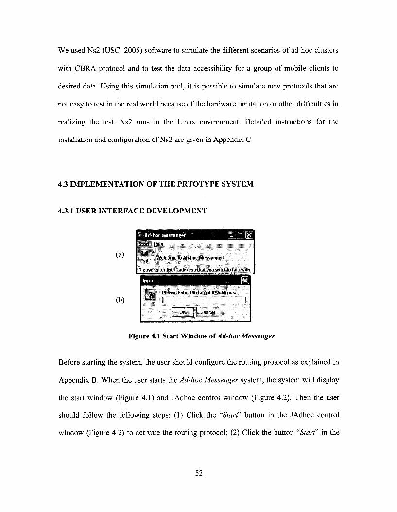
We used Ns2 (USC, 2005) software to simulate the different scenarios of ad-hoc clusters
with CBRA protocol and to test the data accessibility for a group of mobile clients to
desired data. Using this simulation tool, it is possible to simulate new protocols that are
not easy to test in the real world because of the hardware limitation or other difficulties in
realizing the test. Ns2 runs in the Linux environment. Detailed instructions for the
installation and configuration of Ns2 are given in Appendix C.
4.3 IMPLEMENTATION OF THE PRTOTYPE SYSTEM
4.3.1 USER INTERFACE DEVELOPMENT
| Welcome to Ah-hoc Messenger!
Please enter the IPaddress that you want to talk with
Figure 4.1 Start Window of Ad-hoc Messenger
Before starting the system, the user should configure the routing protocol as explained in
Appendix B. When the user starts the Ad-hoc Messenger system, the system will display
the start window (Figure 4.1) and JAdhoc control window (Figure 4.2). Then the user
should follow the following steps: (1) Click the "Start" button in the JAdhoc control
window (Figure 4.2) to activate the routing protocol; (2) Click the button "Start" in the
52
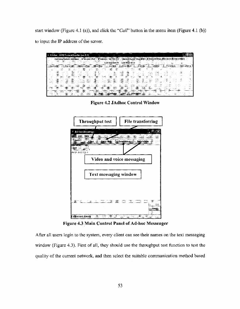
start window (Figure 4.1 (a)), and click the "Call" button in the menu item (Figure 4.1 (b))
to input the IP address of the server.
« J-Adltoc »ODV Protocol Handler (ver 0.2)
Operating System: Windows - IP Version: IPv4 - IP Address: 192.168.12,2
Last Seq Num; 0
Destination ] Sequence ] ^Sequence Flag i Route Flag j interface
| Start j t Configure j
I - IIDJIXJ
- Interface Name: tD<MceWF_{E?86257A.A36A-4BA1-9CE9-8C238C37fJESZ>
LastRREOIDrO
Hop Count ; Next Hop ] Lifetime | Precursors j Hello Lifetime j [
Quit j ^ information •
Figure 4.2 JAdhoc Control Window
Throughput test File transferring
tile luul llulp /
t lus t Sunil I ilus Semi Vuici! finijii VIIIKU
Hiscunntict
L>:n
•Jerry> Just log in
Video and voice messaging
Text messaging window
Connected: Antmry
siSiDfc
Figure 4.3 Main Control Panel of Ad-hoc Messenger
After all users login to the system, every client can see their names on the text messaging
window (Figure 4.3). First of all, they should use the throughput test function to test the
quality of the current network, and then select the suitable communication method based
53
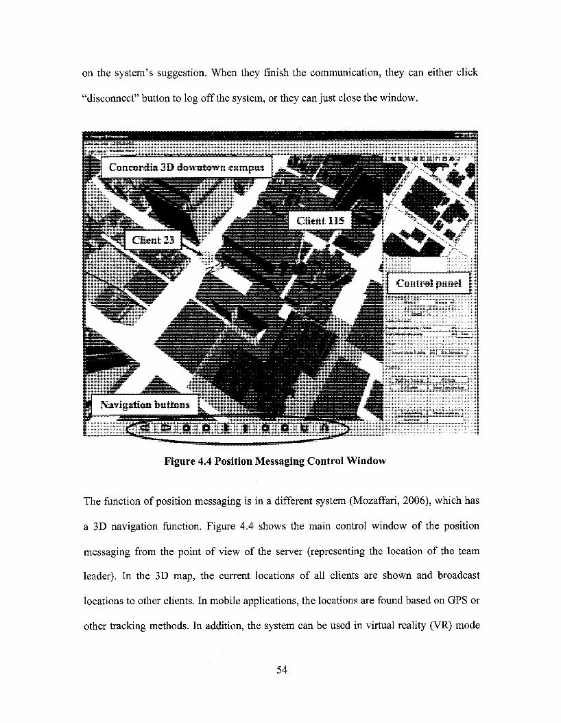
on the system's suggestion. When they finish the communication, they can either click
"disconnect" button to log off the system, or they can just close the window.
Figure 4.4 Position Messaging Control Window
The function of position messaging is in a different system (Mozaffari, 2006), which has
a 3D navigation function. Figure 4.4 shows the main control window of the position
messaging from the point of view of the server (representing the location of the team
leader). In the 3D map, the current locations of all clients are shown and broadcast
locations to other clients. In mobile applications, the locations are found based on GPS or
other tracking methods. In addition, the system can be used in virtual reality (VR) mode
54

for indoor applications, such as training of field workers before they go to the field.
Navigation buttons and the control panel can be used to navigate in the 3D model and the
location of the view platform is used to represent the current location of each user.
4.3.2 FUNCTIONS OF THE PROTOTYPE SYSTEM
(1) Position Messaging
The position messaging is server-client based system, which uses Java socket to transfer
data from the clients to the server. Java threads class is used to collect all information
from different clients. Furthermore, the server uses broadcasting to send location
information to all clients.
(a) Screenshot from Client 115 (b) Screenshot from Client 23
Figure 4.5 Client to Client Monitor
In order to visualize the movement of each client, we use balls to represent clients with
different colors and use their IP addresses as their names. In the system, each client can
see the movement of other clients on the screen using first person view (Figure 4.5). The
55

sever representing the team leader can monitor all clients and see their movements
(Figure 4.4).
S Ad-hoc Messenger
pol Help
Send Message
Jerry> Just log in Jerry> Hi, Antony, where are you now? Antony> Hi, Jerry, I am walking on Guy street, near^Rene Levesque Blvd.
Ok, I saw you
Connected: Jeiu>
I Send
Display window
Input window
Figure 4.6 Text Messaging
(2) Text messaging
The text messaging function is a broadcasting system. Each client types its message in the
input window. After clicking on the send button, all information, including the name and
IP address of the client, will be sent to the sever. Then, the sever uses MULTICAST_
ADDRESS to broadcast this message to all clients. Finally, all clients can see the
message in the display window (Figure 4.6).
(3) Video and Voice communication
In the video and voice communication, we mainly used two Java classes: Real-time
Transport Protocol (RTP) and Java Media Framework API (JMF). RTP has become a
widely implemented Internet-standard protocol for transport of real-time data, including
56

audio and video. It can be used for media-on-demand as well as interactive services such
as Internet telephony. RTP consists of a data and a control parts (RTP, 2006).
The JMF enables audio, video and other time-based media to be added to applications
and applets built on Java technology. This optional package, which can capture, playback,
stream, and transcode multiple media formats, extends the Java 2 Platform, Standard
Edition (J2SE) for multimedia developers, by providing a powerful toolkit to develop
scalable, cross-platform technology (JMF, 2006).
The video and voice communication function is a server-client based system. We used
JMF to capture the video through a digital camera, and then to display the video on the
monitors of other clients. We used RTP to transfer the video stream between clients
(Figure 3.4).
S2> £.3v:fl L_
File:
Size
Speed:
„lj I hl,> l , i . i (
' f, 1):AntoiiyAODVTest-AilhncMessenuer fiiial'ijeueivefileittiojava23.zip Exis
File,.. 11 Sesiri
Interce
i"mojava
ption Status
23.zip" from 192.168.1
Overwrite | Continue Cancel
I I PatiSt | ! Car
• •
6.2 IKI2.168.
•
16.2]:4.1MB..H5.
eel j
SMB
x)
1.
Figure 4.7 Break Point Continue Transmission
57
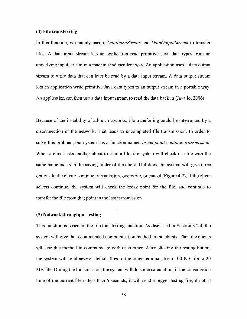
(4) File transferring
In this function, we mainly used a DatalnputStream and DataOutputStream to transfer
files. A data input stream lets an application read primitive Java data types from an
underlying input stream in a machine-independent way. An application uses a data output
stream to write data that can later be read by a data input stream. A data output stream
lets an application write primitive Java data types to an output stream in a portable way.
An application can then use a data input stream to read the data back in (Java.io, 2006).
Because of the instability of ad-hoc networks, file transferring could be interrupted by a
disconnection of the network. That leads to uncompleted file transmission. In order to
solve this problem, our system has a function named break point continue transmission.
When a client asks another client to send a file, the system will check if a file with the
same name exists in the saving folder of the client. If it does, the system will give three
options to the client: continue transmission, overwrite, or cancel (Figure 4.7). If the client
selects continue, the system will check the break point for the file, and continue to
transfer the file from that point in the last transmission.
(5) Network throughput testing
This function is based on the file transferring function. As discussed in Section 3.2.4, the
system will give the recommended communication method to the clients. Then the clients
will use this method to communicate with each other. After clicking the testing button,
the system will send several default files to the other terminal, from 100 KB file to 20
MB file. During the transmission, the system will do some calculation, if the transmission
time of the current file is less than 5 seconds, it will send a bigger testing file; if not, it
58

will stop the transmission. At the end of the test, the system will display the average
throughput of the current connection. Then the user can select the proper mode (text,
voice, or video) and whether he/she can send large files. Figure 4.8 shows an example of
throughput testing. Based on the current throughput, 10.8 MB/sec, the system suggests to
the user to use video communication (Using Table 3.1).
g*ff£Bg3E
msB, fcfll
File: Testingrile\20Mtest.txt
Size: 2O.OMBJ20.0MB
Speed: 10.8MB.'sec 00:00:02
.. i . . The speed is very good, you can use video charting and send big video files!
JPti
Figure 4.8 Throughput Testing in Ad-hoc Messenger
(6) JAdhoc
The original code was developed by Bremen University (ComNets, 2006), and was
modified and combined with our system.
4.4 TESTING THE AD-HOC MESSENGER
As explained in Section 2.2.4, QoS of MANETs includes several issues, such as node
mobility, route maintenance, limited battery life, etc. In this testing, the main focus is on
testing the QoS properties of throughput. The purpose of testing the Ad-hoc Messenger is
to measure the communication throughput of file transfer function under different
59
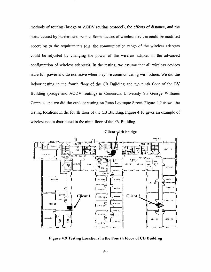
methods of routing (bridge or AODV routing protocol), the effects of distance, and the
noise caused by barriers and people. Some factors of wireless devices could be modified
according to the requirements (e.g. the communication range of the wireless adapters
could be adjusted by changing the power of the wireless adapter in the advanced
configuration of wireless adapters). In the testing, we assume that all wireless devices
have full power and do not move when they are communicating with others. We did the
indoor testing in the fourth floor of the CB Building and the ninth floor of the EV
Building (bridge and AODV routing) in Concordia University Sir George Williams
Campus, and we did the outdoor testing on Rene Levesque Street. Figure 4.9 shows the
testing locations in the fourth floor of the CB Building. Figure 4.10 gives an example of
wireless nodes distributed in the ninth floor of the EV Building.
Client with bridge
/ *"?«»- - • lO
i^.iJjWh, =
F=D=c
• \ m /
Client
•KPI-18-
Figure 4.9 Testing Locations in the Fourth Floor of CB Building
60
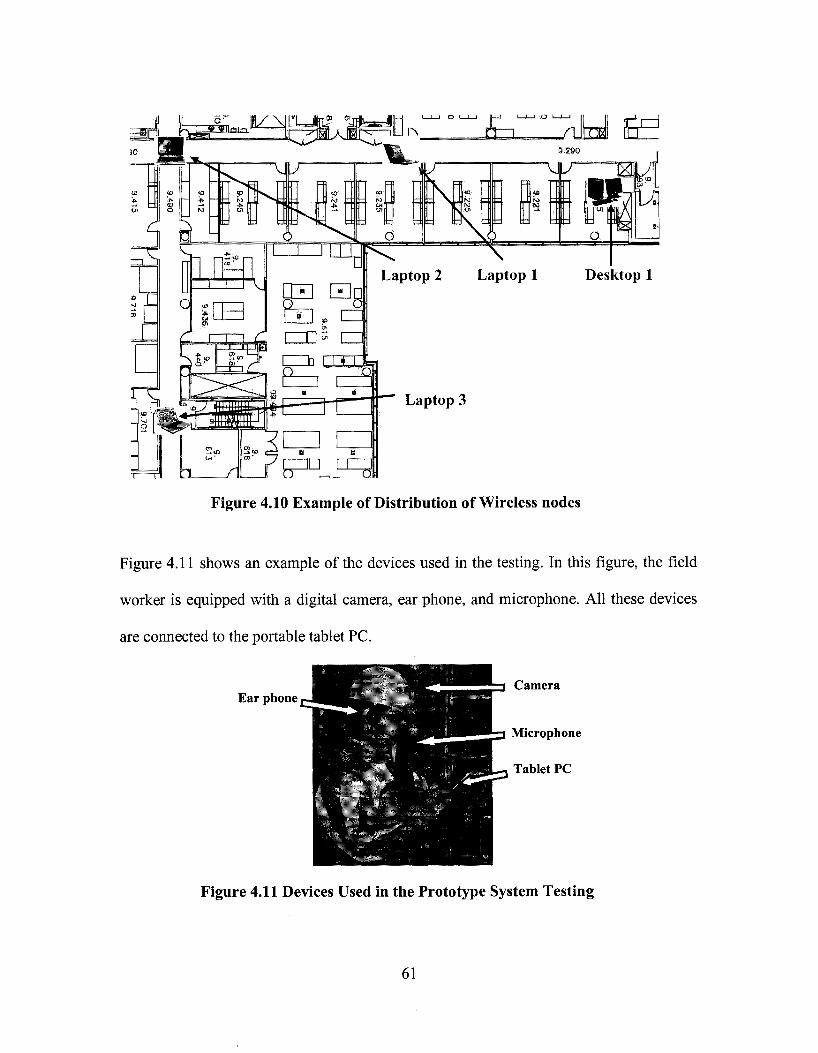
iLisassd!!^
Desktop 1
Figure 4.10 Example of Distribution of Wireless nodes
Figure 4.11 shows an example of the devices used in the testing. In this figure, the field
worker is equipped with a digital camera, ear phone, and microphone. All these devices
are connected to the portable tablet PC.
Ear phone Camera
Microphone
Tablet PC
Figure 4.11 Devices Used in the Prototype System Testing
61
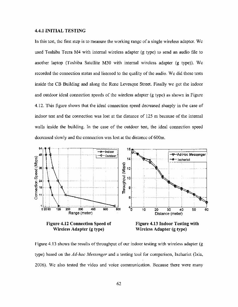
4.4.1 INITIAL TESTING
In this test, the first step is to measure the working range of a single wireless adapter. We
used Toshiba Tecra M4 with internal wireless adapter (g type) to send an audio file to
another laptop (Toshiba Satellite M30 with internal wireless adapter (g type)). We
recorded the connection status and listened to the quality of the audio. We did these tests
inside the CB Building and along the Rene Levesque Street. Finally we got the indoor
and outdoor ideal connection speeds of the wireless adapter (g type) as shown in Figure
4.12. This figure shows that the ideal connection speed decreased sharply in the case of
indoor test and the connection was lost at the distance of 125 m because of the internal
walls inside the building. In the case of the outdoor test, the ideal connection speed
decreased slowly and the connection was lost at the distance of 600m.
Range (meter) Distance (meter)
Figure 4.12 Connection Speed of Figure 4.13 Indoor Testing with Wireless Adapter (g type) Wireless Adapter (g type)
Figure 4.13 shows the results of throughput of our indoor testing with wireless adapter (g
type) based on the Ad-hoc Messenger and a testing tool for comparison, Ixchariot (Ixia,
2006). We also tested the video and voice communication. Because there were many
62

walls in CB Building, the maximum range of video and voice communication with
acceptable quality (Minimum resolution: 352 x 288) was about 25 meters.
In our tests, for each measurement, 20 readings have been collected and the average
values were used in the results. For example, the data in Table 4.1 were collected at the
distance of 20 meters between two wireless devices.
Table 4.1 Sample of Throughputs in the Tests at the Same Position
Throughput (Mbps)
12.459
12.388
11.571
12.352
11.359
11.927
11.383
11.655
11.593
11.951
11.71
12.516
12.585
12.679
11.365
12.549
11.964
12.272
12.3
12.39
11 11,5 12 12.5 Throughputs (Mbps)
Figure 4.14 Probability Density Estimate Curve
14
63

The mean value of these data is 12.048, and the standard deviation is 0.452. According to
these data and their mean and standard deviation we got the probability distribution
estimate curve (Figure 4.14).
Table 4.2 Devices Used in Test-1
Type Laptop 1
Laptop 2
Laptop 3
Wireless adapter 1 Digital camera
Device Dell Precision M65
DellXPSM1210
Toshiba Tecra A8
D-linkWUA-1340 Logitech-3000
Feature Intel Core Duo T2700 2.33GHz, 1GB RAM, a, b,g type Intel Core Duo T2600 2.16GHz, 1GB RAM, a, b,g type Intel(R) Core™ Duo T2400, 1.83 GHz, 1GB RAM, a, b, g type a, b, g type, Connectivity: USB Resolution : 640 x 480 @ 15 fps (video), Connectivity: USB
4.4.2 TEST-1: TEST WITH BRIDGE NODE
As discussed in Section 3.2.5, we introduced our bridge test. Table 4.2 shows the devices
used in this test.
In order to enlarge the communication range of two clients, we used bridge node as the
intermediate node between the clients. Because different wireless adapters form various
companies may not be compatible, we did many tests, and finally selected Laptop 2 and
Wireless adapter 1 to make the bridge. First, we configured these two adapters into two
different domains, and assigned their static IP addresses under ad-hoc mode. Then we let
other wireless devices (Laptop 1 and Laptop 3) join these two domains separately in
ad-hoc mode, and also assigned their static IP addresses. Finally, in Laptop 2, we
combined its two wireless adapters into one bridge, and assigned its static IP address
(details are given in Appendix B). Indoor testing can provide a realistic working
environment (Jadhav et al., 2005), but the internal walls can weaken the strength of the
64

signal. We tested our Ad-hoc Messenger with the bridge node in the EV Building (Figure
4.10), and got the relationship between throughput and distance when moving in the
corridor of the floor to avoid the effects of walls (Figure 4.15). In these tests, we let the
system on laptop3 send a 100 KB file 100 times, and measured the average value of
throughput at each testing position. From the results, we can see that the bridge enlarges
the communication range of wireless adapters compared with Figure 4.13.
4.4.3 TEST-2: TEST USING AODV ROUTING PROTOCOL
In order to avoid the problems of using a bridge as explained in Section 3.2.5, we
introduced another test using AODV routing protocol. In test-2, we tested this method on
the ninth floor of the EV Building of Concordia downtown campus (Figure 4.10). Table
4.3 shows the main devices that we used in this test. In the test, we configured the WEP
security protocol to ensure the security of our network.
Table 4.3 Devices Used in Test-2
Type Desktop 1
Laptop 1
Laptop 2
Laptop 3
Wireless adapter 2 Digital camera
Device IBM IntelliStation M Pro
Dell Precision M65
DellXPSM1210
Toshiba Tecra A8
D-linkWUA-1340 Logitech-3000
Feature Pentium(R) 4, 2.4 GHz, 768MB RAM Intel Core Duo T2700 2.33GHz, 1GB RAM, a, b,g type Intel Core Duo T2600 2.16GHz, 1GB RAM, a, b, g type Intel(R) Core™ Duo T2400, 1.83 GHz, 1GB RAM, a, b, g type a, b, g type, Connectivity: USB Resolution : 640 * 480 @ 15 fps (video), Connectivity: USB
65

In this test, we used desktop 1 connected with wireless adapter 2 (working as the fixed
node), and 2 laptops (working as the moving nodes). On each node, we installed and
configured our Ad-hoc Messenger using AODV routing protocol to connect the whole
wireless network. We distributed these moving nodes on the ninth floor of the EV
Building. The system on each node worked well, and all of them could find and
communicate with the destination node through our system.
In this test, within the range of 20 m, the moving node (Laptop 2) does not need the
intermediate node (Laptop 1) to connect with the destination node (Desktop 1). This is
because the indoor communication range with high ideal connection speed (as Figure
4.12) of a single wireless adapter is about 20 meters. Furthermore, due to the interference
of many factors inside the EV building (e.g. people, University's wireless signals, walls,
etc.), intermediate nodes may not be selected in the routes.
As in test-1, we let the system on laptop3 send a 100 KB file 100 times, and measured the
average value of throughput at each testing position. Figure 4.15 shows the results of our
Ad-hoc Messenger with AODV routing protocol compared with the previous results in
test-1 with a bridge. From the figure we can see that the overall performance of our
system with AODV routing protocol is similar to that with a bridge. However, the
throughput, when using a bridge, was slightly lower than when using AODV in most of
the cases. This could be explained by the internal hardware communications between the
two wireless adapters of the bridge. Few research results where found comparing the
performance of bridging vs. AODV routing in ad-hoc networks. Jacob and Zhou (2004)
66
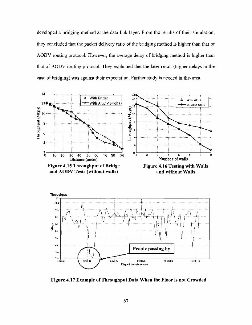
developed a bridging method at the data link layer. From the results of their simulation,
they concluded that the packet delivery ratio of the bridging method is higher than that of
AODV routing protocol. However, the average delay of bridging method is higher than
that of AODV routing protocol. They explained that the later result (higher delays in the
case of bridging) was against their expectation. Further study is needed in this area.
14
12 a e 10
a. 8
M £ 6
I
', •
i i I
1 1 1
-With Bridge -With AfinVMnHre
10 20 30 40 50 60 70 80 90 Distance (meter)
Figure 4.15 Throughput of Bridge and AODV Tests (without walls)
3 4 5 6 Number of walls
Figure 4.16 Testing with Walls and without Walls
Throughput u
0:00:00 0:00:08 0:0(1:10
Figure 4.17 Example of Throughput Data When the Floor is not Crowded
67

Throughput
0:00:00 0:00: 0:00:06 0:00:08 0:00:10 0:00:12 0:00:14 0:00:16 0:00:18 0:00:20 Etapscd time (tKintmss)
Figure 4.18 Example of Throughput Data When the Floor is Crowded
During the testing, we noticed that sometimes the data at the same position could vary
widely, and we found that sometimes the throughput of the system could be almost zero
because of the following factors: (1) The strong wireless signals of Concordia's wireless
network and other electromagnetic waves from other labs in the EV Building. Sometimes
these signals could occupy the channel of the ad-hoc network, which leads to zero
throughput of our system; (2) Walls: We did some tests to check the effect of the
interference of walls (Figure 4.16). The results show that the throughput with walls was
much lower than the throughput without walls; (3) Human bodies (especially in the case
of long range communication): Figures 4.17 and 4.18 show examples of the throughput
data between two clients at a distance of about fifty meters from each other under two
levels of number of people on the same floor. The average throughput values in these two
figures are 7.75 Mbps and 3.96 Mbps, respectively. Moreover, Figure 4.18 shows that the
movement of people near the wireless devices strongly affected the results. In addition,
68

we repeated test-1 and test-2 at different times (e.g. working day and holiday) in the EV
building and found that the throughputs are different at different periods because of
different levels of noise.
4.5 CLUSTERING SIMULATION RESULTS
As we reviewed in Section 2.6.3, many factors could affect the data accessibility. We
modified the code of the scenario file, tcl file, and the aodv file based on different
parameter, as was explained in Section 3.3, and run the simulation. Finally, the results
from the trace file were extracted to study the effects on data accessibilities. In the
simulation, we fixed the values of the following parameters (Table 3.2): total simulation
time is 500 seconds; pause time is 2 seconds; data size is 1 KB; number of original data
items per node is three; memory size of each node is 10 KB; replica allocation period is
100 seconds. In order to make the results more accurate, every simulation was run 5
times, and the average value was calculated as the final result. We analyzed the data
accessibility based on the following four factors:
69

(1) Effect of area size
Six different area sizes were used: 50 x 50 m2, 100 x 100 m2, 200 x 200 m2, 400 x 400
m2, 500 x 500 m2, and 600 x 600 m2, and the other parameters were kept as the default
values (Table 3.2). Figure 4.19(a) shows that the data accessibility depends on the area
size. As the area size increases, the data accessibility decreases.
50100 200 300 400 500 600
(a) Side length of simulation area (ni)
150 200 250
(b) Range (m)
75 r
]?65-
o
55-
50-
20 30 40 (c) Number of Nodes
50 45
0 12345 8 10 15 20 25
(d) Speed of Nodes (m/s)
300
30
Figure 4.19 Effects of Area Size, Range, Node Number, and Speed
(2) Effect of wireless range
Six wireless ranges were used: 50 m, 100 m, 150 m, 200 m, 250 m, and 300 m, and the
other parameters were kept as the default values (Table 3.2). In the real world testing, this
could be realized by changing the power of the wireless adapter in the advanced
70

configuration of wireless adapter. Figure 4.19(b) shows that as the wireless range
increases, the data accessibility increases.
(3) Effect of the number of nodes
Eight node numbers were used: 14, 20, 25, 30, 35, 40, 45, and 50, and the other
parameters were kept as the default values (Table 3.2). Figure 4.19(c) shows that as the
number of nodes increases, the data accessibility increases.
(4) Effect of node speed
Eleven speeds were used: 1 m/s, 2 m/s, 3m/s, 4 m/s, 5 m/s, 8 m/s, 10 m/s, 15 m/s, 20 m/s,
25 m/s, and 30 m/s, and the other parameters were kept as the default values (Table 3.2).
In the real world testing, we can realize these movements by walking, using bicycles, or
cars. Figure 4.19(d) shows that as the speed of the nodes increases, the data accessibility
decreases.
Figure 4.20 shows the screenshots of an animation. In this example, there are 3 clusters
marked with different colors: red, green, and blue. During the simulation, all nodes are
moving randomly, and sending data requests through their cluster heads. Because we
used low-maintenance clustering scheme, if the distance between the node and its cluster
head is too long (out of communication range), the data package will be dropped, which
will lead to the decrease of data accessibility. For example, at time 300 second (Figure
4.20 (a)), all nodes of cluster 3 (node 9, node 10, nodell, node 12, node 13) stayed
together. As time goes by, node 11 moved far away from its cluster head (node 9) as
shown in time 330 second (Figure 4.20 (b)) to time 390 second (Figure 4.20 (d)). During
71
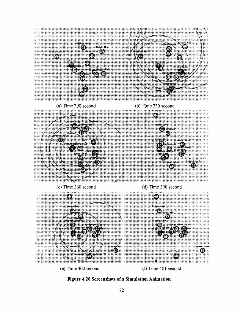
ciiHc-r£ Client
© Cluster! Client
C ustrr E I f r i d
© 0 _ S
c G 8 J z Client ^ " * '
(a) Time 300 second
(c) Time 360 second .;c*r .} •„!:*!•: =
ClUItf- l £ H r l d
(b) Time 330 second
"i Clyster ,* He ld
•Jt*r2CI.*rrt
• _ . u ; " i 1 :.i ••*••( C l u i t e r ^ f A ^ n t
J l t r r E Ci-ent
C lu i tPtVCfKent
© © LMjj'.i-r I C i «••:
ciusteri Client
(d) Time 390 second
Cluster! Held
© lusters Cl ient
© li
8E« 6,
CI lister 2 Client
Cluster HMWnt-•-,,"!?f.51C|;V!tei-icy
^
• ; i - i :**i ' 1 VI -w
•
(e) Time 400 second (f) Time 401 second
Figure 4.20 Screenshots of a Simulation Animation
CIu«et*i Client
©
72
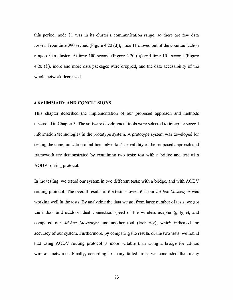
this period, node 11 was in its cluster's communication range, so there are few data
losses. From time 390 second (Figure 4.20 (d)), node 11 moved out of the communication
range of its cluster. At time 100 second (Figure 4.20 (e)) and time 101 second (Figure
4.20 (f)), more and more data packages were dropped, and the data accessibility of the
whole network decreased.
4.6 SUMMARY AND CONCLUSIONS
This chapter described the implementation of our proposed approach and methods
discussed in Chapter 3. The software development tools were selected to integrate several
information technologies in the prototype system. A prototype system was developed for
testing the communication of ad-hoc networks. The validity of the proposed approach and
framework are demonstrated by examining two tests: test with a bridge and test with
AODV routing protocol.
In the testing, we tested our system in two different tests: with a bridge, and with AODV
routing protocol. The overall results of the tests showed that our Ad-hoc Messenger was
working well in the tests. By analyzing the data we got from large number of tests, we got
the indoor and outdoor ideal connection speed of the wireless adapter (g type), and
compared our Ad-hoc Messenger and another tool (Ixchariot), which indicated the
accuracy of our system. Furthermore, by comparing the results of the two tests, we found
that using AODV routing protocol is more suitable than using a bridge for ad-hoc
wireless networks. Finally, according to many failed tests, we concluded that many
73

factors could affect the quality of ad-hoc wireless networks such as noise signals, walls,
and human bodies.
The real-time simulation of the CBRA protocol was implemented with Ns2 in Linux
environment. In the simulation, the effects on data accessibility were studied. The
following results were obtained from the simulation: (1) The data accessibility decreases
with the increase of the area size and the speed of the nodes; (2) The data accessibility
increases with the increase of wireless range and the number of nodes.
74

CHAPTER 5 SUMMARY, CONCLUSIONS, AND FUTURE WORK
5.1 SUMMARY
As we reviewed in Chapter 2, many communication technologies are used on a daily
basis for on-site communication and collaboration. However, many of them have some
disadvantages that may not be suitable for on-site engineering applications. Furthermore,
several routing protocols for ad-hoc networks and some ad-hoc test-beds were presented.
However, the research about the efficient usage of ad-hoc networking in engineering
applications is still limited.
This research presented a new approach to investigate problems related to deploying
ad-hoc wireless networks for supporting on-site communication and collaboration.
Several modes of communication which are common in on-site applications have been
considered including location information, text messaging, voice and video
communications, and file transmission. These modes have been integrated in a prototype
system which can be used for testing the performance based on available ad-hoc network
protocols and using different types of mobile devices. Furthermore, the prototype system
was tested large number of times with a bridge and with AODV routing protocol to test
its practicality and stability.
Finally, the CBRA protocol based on replication and clustering was simulated using Ns2
and tested to investigate the effect on data accessibility. The simulated results of the
performance of this protocol using different scenarios of ad-hoc clusters were analyzed.
75

The results showed the impact of the area size, wireless range, number of nodes, and
node speed on data accessibility.
5.2 CONCLUSIONS AND CONTRIBUTIONS
The conclusions and contributions of this research are grouped into the following items:
(1) A new testing approach was proposed to investigate problems related to deploying
ad-hoc wireless networks for supporting on-site communication and collaboration.
Several modes of communication which are common in on-site applications have
been considered including location information, text messaging, voice and video
communications, and file transmission. A system, Ad-hoc Messenger, which can
support several common modes of on-site communications was designed and
implemented using Java and AODV routing. A Java application, named Jadhoc was
studied and combined with our prototype system. Two types of tests were considered
by using different routing methods: a bridge (manual routing), and self-organized
routing (AODV routing).
(2) The different functions of the system were tested successfully (position and text
messaging, voice and video communications, throughput testing, and routing).
(3) Several wireless devices (laptops, tablet PCs, and different type of wireless adapters)
were used to investigate the effects of the distance, environment (indoor, outdoor,
noise), and routing methods (bridge or AODV routing) on the throughput. The overall
results of the tests showed that our Ad-hoc Messenger was working well on the tests.
76
By analyzing the data we got from large number of tests, we got the indoor and
outdoor ideal connection speed of the wireless adapter (g type), and compared of our
Ad-hoc Messenger and another tool (Ixchariot), which indicated the accuracy of our
system. Furthermore, by comparing the results of the two tests, we found that using
AODV routing protocol is much more suitable than using a bridge for ad-hoc wireless
networks. Finally, according to many failed tests, we concluded that many factors
could affect the quality of ad-hoc wireless networks such as noise signals and electric
waves, walls, and human bodies.
(4) A simulation model based on CBRA was used to test data accessibility. Different
simulation scenarios were applied based on a large number of simulation runs to
study the effects of area size, wireless range, number and speed of nodes on data
accessibility. The following results were obtained from the simulation: (1) The data
accessibility decreases with the increase of the area size and the speed of the nodes; (2)
The data accessibility increases with the increase of wireless range and the number of
nodes.
5.3 FUTURE WORK
While pursuing this research, several limitations have been identified related to the
requirements and the performance of the developed methods and techniques. Future work
will consider the following issues:
77

(1) Further development of the Ad-hoc Messenger system for simulating the CBRA
protocol in real test cases.
(2) The Ad-hoc Messenger video communication function is at present a point to point
system. Future work will extend it to support video broadcasting and multimedia
conferencing based on the mixer method (Khedher et al. 2006).
(3) Studying the effect of using antennas to increase the range of wireless
communication.
(4) Considering other issues of MANET, such as security.
78
REFERENCES
About.com (2007). "Wireless Networking". < http://compnetworking.about.com/ >. June
16th, 2007.
Acharya, S., Franklin, M., and Zdonik, S. (1996). "Prefetching from broadcast disks."
IEEE ICDE'96,276-285.
Aho, A.V., Hopcroft, J.E., and Ulman, J.D. (1974). "The Design and Analysis of
Computer Algorithms." Addison-Wesley, 1974.
Aldunate, R., Ochoa, S. F., Pena-Mora F., and Nussbaum, M. (2006). "Robust Mobile
Ad-hoc Space for Collaboration to Support Disaster Relief Efforts Involving
Critical Physical Infrastructure." ASCE Journal of Computing in Civil
Engineering, Vol. 20, No. 1, 13-27.
ARC Communications Research Network (2006). "Characteristics of Ad-hoc networks."
<http://www.acorn.net.au>. (March 6, 2006).
Aziz, M., and Al-Akaidi, M. (2007). "Security Issues in Wireless Ad-Hoc Networks and
the Application to the Telecare Project." Digital Signal Processing, 15th
International Conference on 1-4 July 2007, 491-494.
Beyh, S., and Kagioglou, M. (2004). "Construction Sites Communications Towards the
Integration of IP Telephony." Journal of Information Technology in Construction
(ITCon) Vol. 9, 325-344.
Buchegger, S., Eres, C , and Boudec, J. (2004). "A Test-Bed for Misbehavior Detection
in Mobile Ad-hoc Networks — How Much Can Watchdogs Really Do?" In Proc.
the Sixth IEEE Workshop on Mobile Computing Systems and Applications,
102-111.
79

Charles, E., Elizabeth, M., and Barbara, S. (2003). "Ad-hoc On-Demand Distance Vector
(AODV) Routing." <http://www.ee.iitb.ac.in/~comlab/seminar/nishantl_Refl .pdf
>.
Chatterjee, M., Das, S. K., and Turgut, D. (2000). "An On-Demand Weighted Clustering
Algorithm (WCA) for Ad-hoc Networks." In Proc. IEEE Globecom'00, 2000,
1697-1701.
Chiang, C. C , and Gerla, M. (1997). "Routing in Clustered Multi hop, Mobile Wireless
Networks with Fading Channel." Proc. IEEE SICON'97, 546-551.
Chlamtac, I., Conti, M., and Liu, J. J. N. (2003). "Mobile ad-hoc networking: Imperatives
and challenges." Ad-Hoc Networks, Vol. l,No. 1, 13-64.
ComNets (2006). "JAdhoc System Design Manual." Communication networks,
University of Bremen. <http://www.comnets.uni-bremen.de/typo3site/>.
(September, 6th, 2006).
Computing unplugged (2007). "Definition of Quality of services." (2007).
<http://www.computingunplugged.com>. (March 16, 2007).
DSG (2006). "Introduce of wireless Ad-hoc network for Dublin."
<http://www.dsg.cs.tcd.ie/dynamic/7category_id-2>. (June 12,2006).
Ephremides, A., Wieselthier, J. E., and Baker, D. J. (1987). "A Design Concept for
Reliable Mobile Radio Networks with Frequency Hopping Signaling." Proc.
IEEE, Vol. 75, 56-73.
Gerla, M., and Tsai, J.T.C. (1995). "Multicluster, mobile, multimedia radio network."
ACM-Baltzer Journal of Wireless Networks, Vol. 1, No. 3, 1995, 255-265.
IEEE (2006). "IEEE standards." <http://www.ieee.com>. (March 3, 2006)
80
Hara, T. (2001). "Effective Replica Allocation in Ad-hoc Networks for Improving Data
Accessibility." IEEE INFOCOM 2001, 1568-1576.
Hu, Y. (2006). "Mobile Location-Based Bridge Inspection Decision-Support System."
Master thesis in department of Building, Civil and Environmental Engineering,
Concordia University, February 2006.
Iglobility.com (2007). "Dedicated to Global Digital Mobility." <
http://www.iglobility.com>. June 16 , 2007.
Ixia (2006). "Ixia wireless solutions." <http://www.ixiacom.com/solutions/wireless>
(May 6, 2006).
Jacob, L., and Zhou, L. (2004). "A Bridging Method for Mobile Ad Hoc Network
Routing and its Performance." IASTED International Conference on Advances in
Computer Science and Technology (ACST 2004), US Virgin Island, Nov 2004.
Jadhav, S., Brown, T. X., Doshi, S., Henkel, D., and Thekkekunnel, R. G. (2005).
"Lessons Learned Constructing a Wireless Ad-Hoc Network Test Bed." In Pro.
the 1st International Workshop on Wireless Network Measurement (WiNMee),
Trentino, Italy, April 2005.
Java.io (2006). "Java IO package." < http://java.sun.eom/j2se/l.4.2/docs/api/java/io/
package-summary.html>. (May 22,2006).
Jiang, M., Li J., and Tay, Y. C. (1999). "Cluster Based Routing Protocol (CBRP)
Functional Specification." IETF Internet Draft, draft-ietfmanet-cbrp-spec-01.txt.
JHU (2006). "Shuttle Bus Project in JHU ." <http://wireless.cs.jhu.edu/mobile/>. (June
12, 2006).
81

JMF (2006). "Java Media Framework API (JMF)." < http://java.sun.com/products/java-
media/jmf/>. (March 8, 2006).
Khedher, D. B., Glitho, R. H., and Dssouli, R. (2006). "Media Handling Aspects of
Multimedia Conferencing in Broadband Wireless Ad-Hoc Networks." IEEE
Network, March/April, 2006,42-49.
Kuladinithi, K., Timm-Giel, A., and Gorg, C. (2003). "Potential Productivity Gains in the
Field through Wireless Technologies." In Pro. the 10th ISPE International
Conference on Concurrent Engineering, 725-731.
Kuladinithi, K., Timm-Giel, A., and Gorg, C. (2004). "Mobile Ad-hoc Communications
in AEC industry." Journal of Information Technology in Construction (ITcon)
Vol. 9,313-323.
Kwon, T. J., Gerla, M., Varma, V., Barton, M., and Hsing, T. R. (2003). "Efficient
Flooding with Passive Clustering - an Overhead-Free Selective Forward
Mechanism for Ad-hoc/Sensor Networks." In Proc. IEEE, Vol. 91, No. 8, August
2003, 1210-1220.
Lee, F., Kimm, H., and Reinhart, C. (2007). "A Globla On-Demand Routing Protocol for
Mobile Ad-Hoc Networks." Sixth IEEE International Symposium on Network
Computing and Applications, 0-7695-2922-4/07.
Lee, S.J., Royer, E. M., and Perkins, C. E. (2003). "Scalability Study of the Ad-Hoc
on-Demand Distance Vector Routing." ACM/Wiley International Journal of
Network Management, Vol. 13, 97-114.
Li, J. (2006). "Quality of Service (QoS) Provisioning in Multi hop Ad-Hoc Networks."
Ph.D. thesis of University of California, Computer Science Department.
82
Macker, J., and Corson, S. (1997). "Mobile Ad-Hoc Networks (MANET)." IETF WG
Charter, <http://www.ietf.org/html.charters/manet-charter.html>.
Mahboob, F. (2005). "Caching and Replication to Improve Data Accessibility in Mobile
Ad-hoc Networks." Internal report. Faculty of engineering and computer science,
Concordia University.
Mozaffari, E. (2005). "Virtual Reality Models for Location-Based Facilities Management
systems." 1st CSCE Specialty Conference on Infrastructure Technologies,
Management and Policy, Toronto, Ontario, Canada.
Mozaffari, E. (2006). "Creating and Testing Urban Virtual Reality Models for
Engineering Applications." Master thesis in department of Electrical and
Computer Engineering, Concordia University, May 2006.
OPNET Technologies (2007). "OPNET solutions." <http://www.opnet.com>. (May 8,
2007)
Parks Associates (2007). "Research and analysis for digital living technologies." <
http://www.parksassociates.com>. June 16th, 2007.
Prasant, M. (2004). "AD-HOC NETWORKS Technologies and Protocols." 2004, XXIV,
272 p., Hardcover. ISBN: 978-0-387-22689-7.
RTP (2006). "Java RTP implementation." <http://www.cs.columbia.edu/~hgs/teaching/
ais/1998/projects/java_rtp/report.htm>. (May 18, 2006).
Sanghani, S., Brown, T. X., Bhandare, S., and Doshi, S. (2003). "EWANT: The Emulated
Wireless Ad-Hoc Network Testbed." IEEE 0-7803-7701-X/03, 1844-1849.
Search Mobile Computing (2007). "Mobile computing Information resource."
<http://www.searchmobilecomputing.com>. (June 16, 2007).
83

SR Telecome (2007). "Fixed Wireless Data Networking Architecture Overview." <
http://www.srtelecom.com/en/products/whitepapers/Fixed-Wireless-Data-Networ
king.pdiX June 16th, 2007.
Toh, C.K., Lee, E. C , and Ramos, N. A. (2004). "Next-Generation Tactical Ad-Hoc
Mobile Wireless Networks." Technology Review Journal, Spring/Summer, 2004.
103-116.
UCLA Parallel Computing Laboratory (2007). "GloMoSim simulation tool."
<http://pcl.cs.ucla.edu/projects/ glomosim>. (May 9,2007).
USC (2005). "Ns simulation tool. " <http://www.isi.edu/nsnam/ns>. (Nov. 12, 2005).
Vinayakray-Jani, P. (2002). "Security within Ad-hoc Networks." Position Paper,
PAMPAS Workshop, September, 2002, London.
Ward, M., Thorpe, T., Price, A., and Wren, C. (2004). "Implementation and control of
wireless data collection on construction sites." ITcon Vol. 9, 297-311.
Wi-Fi (2003). "Securing WiFi Wireless Networks with Today's Technology." White
paper, WiFi Alliance, 6 February, 2003. <http://www.wifi.org>.
Wi-Fi planet (2007). "Top 40 Wireless Terms". < http://wi-fiplanet.webopedia.com/ >.
June 16th, 2007.
WiMAX forum (2007). "WiMAX Technology." <http://www.wimaxforum.org>. June
16th, 2007.
WMC (2006). "Wireless and Mobile Communications." <http://www.ti-wmc.nl/>. (Oct.
9th, 2006).
Xu, B., and Hischke, S. (2003). "The Role of Ad-hoc Networking in Future Wireless
Communications." In Pro. ICCT2003, 1353-1358.
84
Yang, L. and Hammad, A. (2007). "Ad-hoc Wireless Networking for Supporting
Communication and On-Site Data Collection", ASCE Workshop on Computing in
Civil Engineering 2007, July 2007, Pittsburgh, PA, U.S.A., 854-861.
Yu, J., and Chong, P. (2005). "A Survey of Clustering Schemes for Mobile Ad-hoc
Networks." IEEE Communication Surveys and Tutorials, First Quarter 2005, Vol.
7, No. 1,2005,32-48.
85

APPENDIX A SOFTWARE REQUIREMENTS AND INSTALLATION GUIDE OF THE PROTOTYPE SYSTEM
SOFTWAR REQUIREMENTS:
(1) Borland JBuilder 2006 Enterprise: used to develop and run the prototype system of Ad-hoc Messenger,
(2) Windows XP: used as the operating system.
INSTALLATION GUIDE:
Install the following software in the specified order: 1. Because the position messaging function is combined with our 3D maps of Concordia downtown campus, the installation guide of this part please read the thesis of Yongxin Hu, "Mobile Location-Based Bridge Inspection Decision-Support System", Appendix F. (Hu, 2006)
2. Drivers of the digital camera are required, which are used for the video communication.
3. JMF (Java Media Framework API) - version 2.1.1 Download the library form: http://java.sun.eom/products/java-media/jmf/2.1.1/
download.html and install it after you install the driver of the camera.
4. Jadhoc (AODV routing protocol) - version 0.2 Download the library form: http://www.aodv.org/modules.php?op-modload&name-
UpDownload&file=index&req:=viewdownload&cid=2 and install it according to the following instructions:
(1) Install WinPcap for Windows (http://winpcap.polito.it) and run the application WinPcap.exe;
(2) Install Jpcap (http://netresearch.ics.uci.edu/kfujii/jpcap/doc/index.html) and add its path to the JBuilder's library;
(3) Copy all application (*.exe) files in Awindows-xp-tools directory to the system commands directory specified in the JAdhoc configuration file. (C: \Windows\sy stem3 2);
(4) Set environment for JAdhoc, set JADHOC=C:\jadhoc-0.2, and set CLASSPATH= %JADHOC%;%JADHOC%\utils;%CLASSPATH%.
86
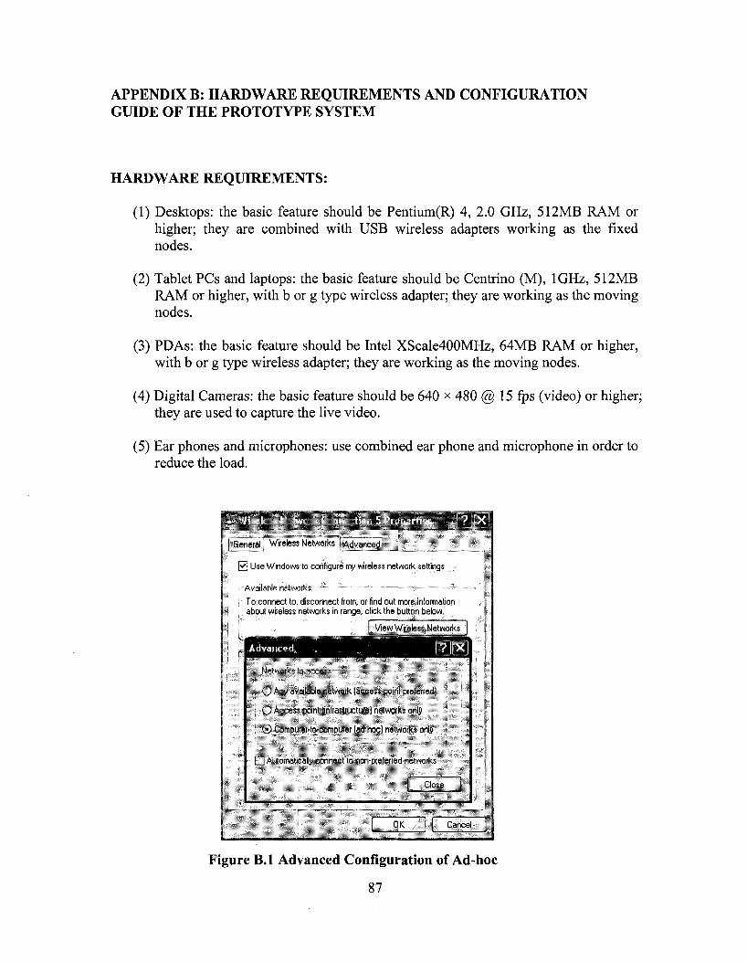
APPENDIX B: HARDWARE REQUIREMENTS AND CONFIGURATION GUIDE OF THE PROTOTYPE SYSTEM
HARDWARE REQUIREMENTS:
(1) Desktops: the basic feature should be Pentium(R) 4, 2.0 GHz, 512MB RAM or higher; they are combined with USB wireless adapters working as the fixed nodes.
(2) Tablet PCs and laptops: the basic feature should be Centrino (M), 1GHz, 512MB RAM or higher, with b or g type wireless adapter; they are working as the moving nodes.
(3) PDAs: the basic feature should be Intel XScale400MHz, 64MB RAM or higher, with b or g type wireless adapter; they are working as the moving nodes.
(4) Digital Cameras: the basic feature should be 640 x 480 @ 15 fps (video) or higher; they are used to capture the live video.
(5) Ear phones and microphones: use combined ear phone and microphone in order to reduce the load.
General Wireless Networks Advanced!
0 Use Windows to configure my wireless network settings
/ Available networks: • •
1 To connect to, disconnect from, or find out more information I about wireless networks in range, click the button below.
View Wireless Networks
Advanced
Networks So access
O Any available network (access point preferred]
O Access point (infrastructure) networks only
; © Computer-to-computer (ad hoc) networks only
• Automatically connect to non-preferred networks
Close
QK: Cancel
Figure B.l Advanced Configuration of Ad-hoc
87

CONFIGURATION GUIDE:
In the advanced configuration of the wireless adapter properties, "networks to access" should be changed from "Any available network (access point preferred) to "Computer -to-computer (ad-hoc) networks only (Figure B.l).
Furthermore, if the wireless device is the first device in the ad-hoc wireless network, a new wireless network domain should be initialized (e.g. in Figure 3.4, a new network domain named "Dlink"). Accordingly, Wired Equivalent Privacy (WEP) option should be added to the new network properties in order to provide security to the ad-hoc wireless network. In the properties of the new network, the "Network Authentication" should be changed to "Open", and the "Data encryption" should be changed to "WEP". Then the user can input the private "Network key" (Figure B.2).
Dlink properties
General | Wireless Networks [Advanced]
@ Use Windows to configure my wireless network settings
Available networks:
To connect to, disconnect from, or find out more information about wireless networks in range, click the button below.
View Wireless Networks
Preferred networks: • Automatical!1 connect to available networks in the order listed below:
3> Dlink (Automatic) M i.-"ii|i
M , A . J . W I
Add... Remove Properties
Learn about setting up wireless network configuration.
Advanced
OK Cancel
Association Authentication II Connection I
Network name (SSID): D!;i
Wireless network key
This network requires a key for the following:
Network Authentication:
Data encryption: I WEP
Network key:
Key index (advanced):
####«## ~™~,.~™~™.**, J
f~l The key is provided for me automatically
• 1 hie i; "J roinpt'tfr to co;ni«ircr ud hue I netful
OK | Cancel
Figure B.2 Configuration of Wireless Network
If the wireless device is not the first device in the ad-hoc network, after the ad-hoc mode was changed, the window system can detect the available ad-hoc networks (Figure B.3), then the user can select which ad-hoc wireless network should join, and input the correct network key (Figure B.4).
88
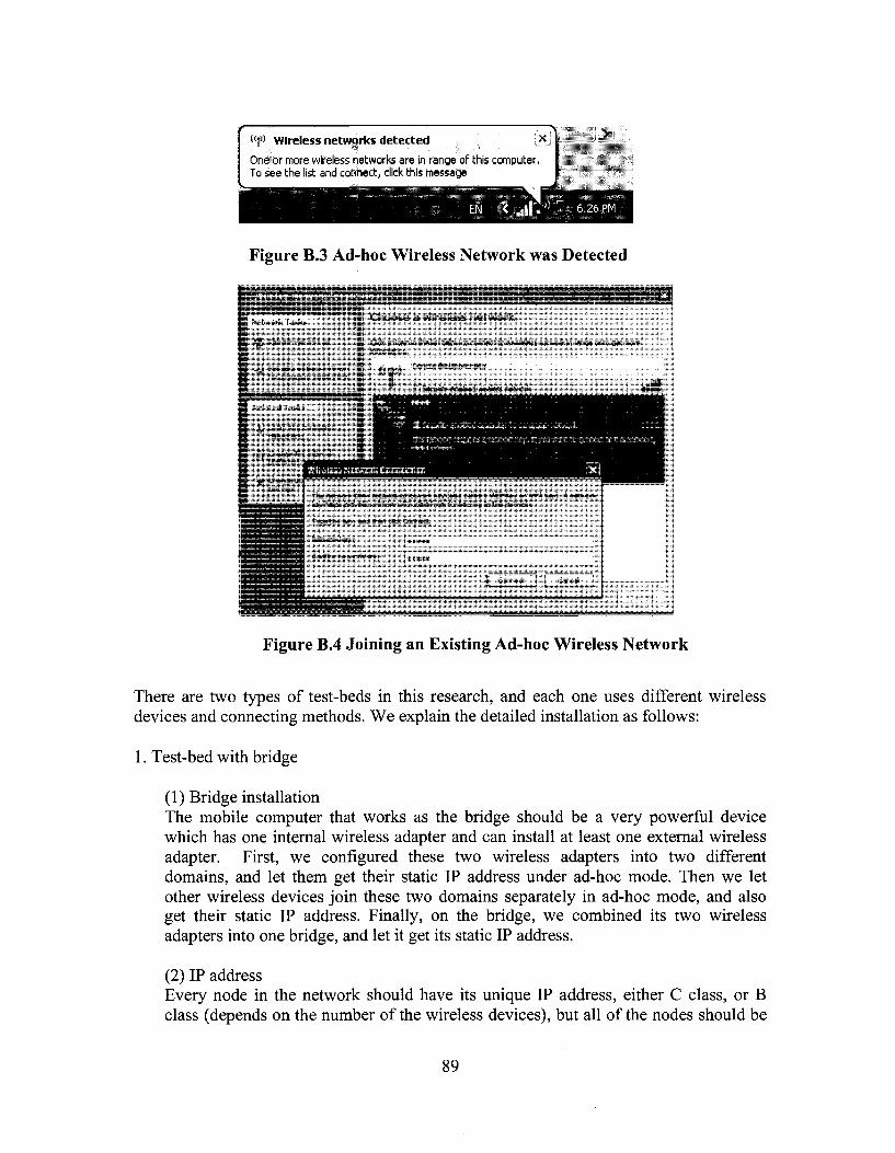
{<!» wireless networks detected I.5
One or more wireless networks are in range of this computer. To see the list and connect, click this message
' < . , l l l - ' ; ^ 6 | 2 6 P M
Figure B.3 Ad-hoc Wireless Network was Detected
tafeasDmmm I f Network Tasl
I..
y • '•'I l l i - l l l . i s k h
i * : v — •• • i"; LV ';(•:..-., r, : . ;—li-'r I
Choose a wireless network
Click an Item in the list below to connect to a wireless network in range or to get more information,
f,^',- Concordiallniversity
; !" " 7 Security-enabled wireless network I
f t Security-enabted computer-to-computer network " :;;J;
This network requires a n&toork. key. it; you want: to connect to this network,
SM:
Wireless Network Connection
The r.c:v.c-l- 'D n* recj-esaretAO^-jcy (alsc ca-ed a vVE3-je/0'WPA-jev!. AnetAorp -ey he 55 preverK jrk^cAT ir:rjce.-s f-err CDnne:t -g re this ie:v«-k.
T-*pecrekey, ard:l"eTd:kCcire:t
MstA-ois-jey. • • • • •
Col fi'rr rcl/.'C.*-'. *jc,-: « • • • «
[ Connect
Figure B.4 Joining an Existing Ad-hoc Wireless Network
There are two types of test-beds in this research, and each one uses different wireless devices and connecting methods. We explain the detailed installation as follows:
1. Test-bed with bridge
(1) Bridge installation The mobile computer that works as the bridge should be a very powerful device which has one internal wireless adapter and can install at least one external wireless adapter. First, we configured these two wireless adapters into two different domains, and let them get their static IP address under ad-hoc mode. Then we let other wireless devices join these two domains separately in ad-hoc mode, and also get their static IP address. Finally, on the bridge, we combined its two wireless adapters into one bridge, and let it get its static IP address.
(2) IP address Every node in the network should have its unique IP address, either C class, or B class (depends on the number of the wireless devices), but all of the nodes should be
89

in the same subnet domain. Usually, we assign the gateway IP address to the bridge node.
Examples:
C Class subnet: Bridge (Gateway):
Other nodes:
B Class subnet: Bridge (Gateway):
Other nodes:
IP address: 192.168.16.1 Subnet mask: 255.255.255.0 Gateway: 192.168.16.1
IP address: 192.168.16.* (2-254) Subnet mask: 255.255.255.0 Gateway: 192.168.16.1
IP address: 169.254.0.1 Subnet mask: 255.255.0.0 Gateway: 169.254.0.1
IP address: 169.254.*.* Subnet mask: 255.255.0.0 Gateway: 169.254.0.1
2. Test-bed with AODV routing protocol
In this test-bed, every node could become the intermediate node, so every one of them should install our prototype system, Ad-hoc Messenger (which includes JAdhoc function).
(1) IP address Each node in this test-bed could be assigned to the same subnet or to a different subnet (Depending on the number of the wireless devices), but the gateway IP address could not be used. We give examples of how we assign IP addresses to the nodes in our testing as follows:
Nodel:
Node 2:
Node 3:
IP address: 192.168.12.2 Subnet mask: 255.255.255.0 Gateway: 192.168.12.1
IP address: 192.168.16.2 Subnet mask: 255.255.255.0 Gateway: 192.168.16.1
IP address: 192.168.8.2
90
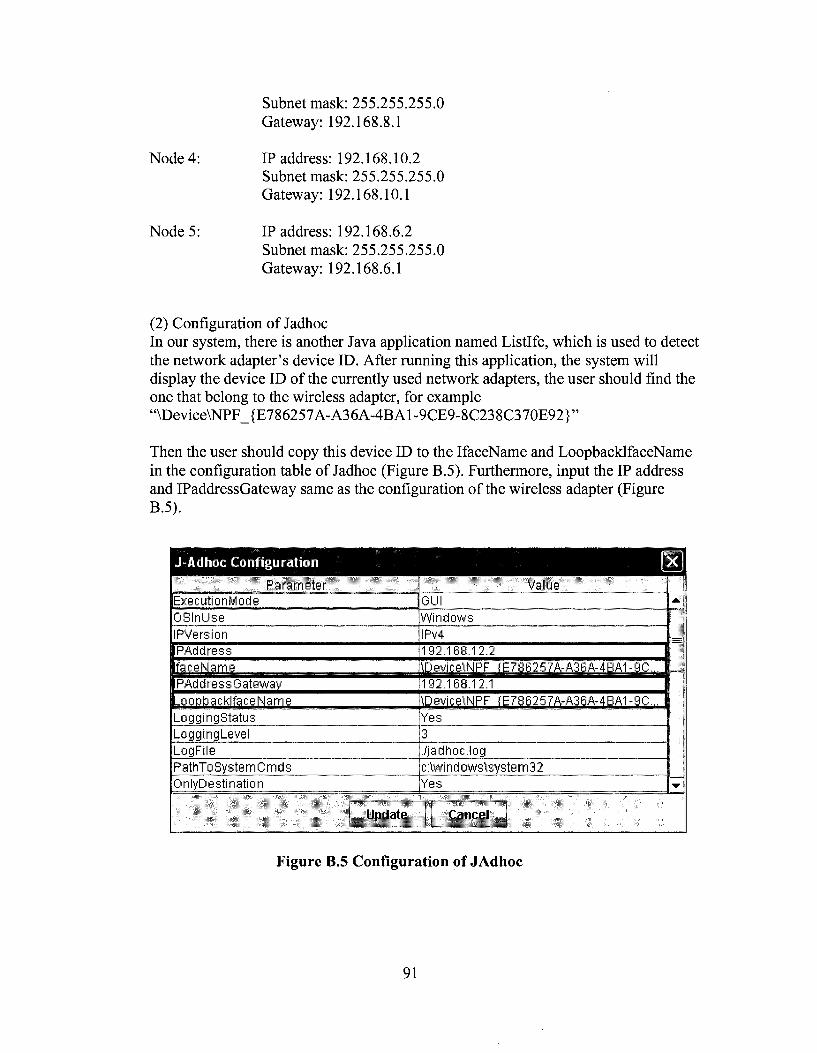
Subnet mask: 255.255.255.0 Gateway: 192.168.8.1
Node 4: IP address: 192.168.10.2 Subnet mask: 255.255.255.0 Gateway: 192.168.10.1
Node 5: IP address: 192.168.6.2 Subnet mask: 255.255.255.0 Gateway: 192.168.6.1
(2) Configuration of Jadhoc In our system, there is another Java application named Listlfc, which is used to detect the network adapter's device ID. After running this application, the system will display the device ID of the currently used network adapters, the user should find the one that belong to the wireless adapter, for example "\Device\NPF_{E786257A-A36A-4BAl-9CE9-8C238C370E92}"
Then the user should copy this device ID to the IfaceName and LoopbacklfaceName in the configuration table of Jadhoc (Figure B.5). Furthermore, input the IP address and IPaddressGateway same as the configuration of the wireless adapter (Figure B.5).
J-ft d hoc Configuration [l
Parameter ExecutionMode OSInUse IPVersion IPAddress faceNarne PAddressGatewav -ooobacklfaceName LoggingStatus LoggingLevel LogFile PathTo System Cmds OnlyDesti nation
Value GUI Windows IPv4 192.168.12.2 \Device\NPF (E786257A-A36A-4BA1-9C... 192.168.12.1 \Device\NPF (E786257A-A36A-4BA1-9C... Yes 3 ./jadhoc. log c:\windows\systern32 Yes
Update Cancel
Jk.
•w
Figure B.5 Configuration of JAdhoc
91

APPENDIX C: SIMULATION TOOLS AND INSTALLATION GUIDE
The simulation part of this research is the continuation of one of our previous colleague's work. Because he deleted all the system on his desktop, we had to spend a lot of time to install and configure the system. However, because both the Linux and Ns2 updated to new versions, we had to solve compatibility problems that new version of Ns2 could not run on new version of Linux. During this period, we also found other problems, for example, the previous coding has some problems, and could not be run.
In the following we will explain the detailed information, so the future researchers can continue this work smoothly.
1. Installation of Linux We used Fedora Linux Core 4.
2. Installation of Ns2
We used version Ns2.28 with the patch file for Fedora Linux Core 4.
In the windows interface of Linux:
(l)Unzip the file named "ns2.tar.gz" into the folder "ns".
(2) Run the Linux terminal (Figure C.l).
(3) Go to the directory "ns/ns-allinone2.28/", then type "./install".
(4) Copy the patch file named "ns2P.patch" to ns/ns-allinone-2.28/ns-2.28. (5) Configure the environment setting following the instruction of the terminal after
the installation is complete and successful.
(6) In the directory of ns/ns-allinone-2.28/ns-2.28, type "make clean".
(7) In the directory of ns/ns-allinone-2.28/ns-2.28, type "patch -pO < ns2P.patch.
(8) Go to ns/ns-allinone-2.28/ns-2.28 and type "./configure", then "make" command.
(9) The installation should be fine and to make sure that there will be no error when you run any simulation: go to ns/ns-allinone-2.28/ns-2.28 and type "./validate".
92

3. Example source code of modified version of the simulation code developed in
(Mahboob, 2005)
Clustering.tcl
1 by Linchuan Yang########
# Define options #
set val(chan) set val(prop) set val(netif) set val(raac) set val(ifq) set val(H) set val(ant) set val(x) topography set val(y) the topography set val(ifqlen) packet in ifq set val(seed)
Channel/WirelessChannel Propagation/TwoRayGround
Phy/WirelessPhy Mao/802_11
Queue/DropTail/PriQueue LL Antenna/OmniAntenna
300 ;# X dimension of the
300 ;# Y dimension of
100 ;# max
0.0 set val(adhocRouting) AODV set val(nn) 14 ;# how many nodes are simulated set val(cp) set val(sc) set val(stop) simulation time
#
mi
"./default-scene-14-cluster" 500.0 ;#
# Main Program #
Phy/WirelessPhy set Pt_ 10.5872e-3.1 #Mac/802 11 set dataRate l le6
# Initialize Global Variables #
# create simulator instance
set ns [new Simulator]
# set up for hierarchical routing #$ns_ node-config -addressType hierarchical AddrParams set domain_num_ 1 ;# number of domains lappend cluster_num 3 ;# number of clusters in each domain AddrParams set cluster_num_ Scluster_num lappend eilastlevel 4 5 5 ;# number of nodes in each cluster AddrParams set nodes_num_ Seilastlevel ;# of each
domain
# setup topography object
set topo [new Topography]
# create trace object for ns and nam
set tracefd [open replicationl4.tr w] $ns_ trace-all Stracefd #$ns_ use-newtrace
set namtrace [open replicationl4.nam w] $ns_ trace-all Stracefd $ns_ namtrace-all-wireless Snamtrace $val(x) $val(y)
# define topology
Stopo loadjlatgrid $val(x) $val(y)
# Create God
set god_ [create-god Sval(nn)]
set channel 1 [new Sval(chan)]
# define how node should be created # global node setting
$ns_ node-config -adhocRouting Sval(adhocRouting) \ -HType $val(ll) \ -macType $val(mac) \ -ifqType Sval(ifq) \ -ifqLen Sval(ifqlen) \ -antType Sval(ant) \ -propType Sval(prop) \ -phyType Sval(netif) \ -channel Schannell \
-topolnstance Stopo \ -agentTrace ON \
-routerTrace ON \ -macTrace ON \
# Create the specified number of nodes [Sval(nn)] and "attach" them # to the channel.
for {set j0} {$j < $val(nn)} {incrj} { set node_($j) [$ns_ node]
}
SnodeJO) label "Cluster 1 Head" SnodeJO) label-color "red" $node_(0) shape "box"
$node_(l) label "Cluster 1 Client" $node_(l) label-color "red"
$node_(2) label "Cluster 1 Client" $node_(2) label-color "red"
$node_(5) label "Cluster 1 Client" $node_(5) label-color "red"
$node_(3) label "Cluster 2 Head" $node_(3) label-color "blue" $node_(3) shape "box"
93

$nodeJ4) label "Cluster 2 Client" $node_(4) label-color "blue"
$node_(6) label "Cluster 2 Client" $node_(6) label-color "blue"
$node_(7) label "Cluster 2 Client" $node_(7) label-color "blue"
$node_(8) label "Cluster 2 Client" $node_(8) label-color "blue"
$node_(9) label "Cluster 3 Head" $node_(9) label-color "green" $node_(9) shape "box"
$node_(10) label "Cluster 3 Client" $node_(10) label-color "green"
$node_(l 1) label "Cluster 3 Client" $node_(l 1) label-color "green"
$node_(12) label "Cluster 3 Client" $node_(12) label-color "green"
$node_(13) label "Cluster 3 Client" $node_(13) label-color "green"
# Traffic
for {set c 0} {$c <= 13} {incr c} { set agent_($c) [new Agent/Ping]
}
for {set dO} {$d <= 13} {incrd} { $ns_ attach-agent Snode_($d)
$agent_($d) }
# Connecting Agents
for {setaO} {$a<= 13} {incr a} { forfsetbO} {$b<= 13} {incrb} {
Sns_ connect SagentJSa) SagentJSb)
#Schedule Events
for{setp0} {$p<= 13} {incrp} {
set e 0.0 while {$e <= 500} {
$ns_ at $e "SagentJ$p) sendO" set e [expr $e - (l/0.41)*log(rand())]
} }
# At 99 Sec.
# CM to CH
set ping_(0) [new Agent/Ping] $ns_ attach-agent SnodeJO) Sping JO) setping_(l) [new Agent/Ping] $ns_ attach-agent $node_(l) $ping_(l)
#Connect the two agents $ns_ connect $ping_(0) $ping_(l) #Schedule events $ns_ at 99.0 "Spingjl) send"
set ping_(5) [new Agent/Ping] $ns_ attach-agent $node_(5) $ping_(5) #Connect the two agents $ns_ connect $ping_(5) $ping_(0) #Schedule events $ns_ at 99.0 "$ping_(5) send"
set ping_(2) [new Agent/Ping] $ns_ attach-agent Snode_(2) $ping_(2) #Connect the two agents $ns_ connect $ping_(2) $ping_(0) #Schedule events $ns_ at 99.0 "$ping_(2) send"
set ping_(3) [new Agent/Ping] $ns_ attach-agent $node_(3) SpingJ3) set ping_(4) [new Agent/Ping] $ns_ attach-agent $node_(4) $ping_(4) #Connect the two agents $ns_ connect $ping_(4) $ping_(3) #Schedule events $ns_ at 99.0 "$ping_(4) send"
set ping_(6) [new Agent/Ping] $ns_ attach-agent $node_(6) $ping_(6) #Connect the two agents $ns_ connect $ping_(6) $ping_(3) #Schedule events $ns_ at 99.0 "$ping_(6) send"
set ping_(7) [new Agent/Ping] $ns_ attach-agent $node_(7) $ping_(7) #Connect the two agents $ns_ connect $ping_(7) $ping_(3) #Schedule events $ns_ at 99.0 "$ping_(7) send"
set ping_(8) [new Agent/Ping] $ns_ attach-agent $node_(8) SpingJ8) #Connect the two agents $ns_ connect $ping_(8) $ping_(3) #Schedule events $ns_ at 99.0 "$ping_(8) send"
set ping_(9) [new Agent/Ping] $ns_ attach-agent $node_(9) SpingJ9) set ping_(10) [new Agent/Ping] $ns_ attach-agent $node_(10) SpingJIO) #Connect the two agents $ns_ connect SpingJIO) $ping_(9) #Schedule events $ns_ at 99.0 "SpingJIO) send"
set ping J11) [new Agent/Ping] $ns_ attach-agent Snodejl 1) Spingjl 1) #Connect the two agents $ns_ connect Spingjl 1) Sping J 9 ) #Schedule events $ns_ at 99.0 "Spingjl 1) send"
set pingJ12) [new Agent/Ping] $ns_ attach-agent Snodejl2) Spingjl2) #Connect the two agents $ns_ connect Spingjl 2) SpingJ9) #Schedule events
94
$ns_ at 99.0 "SpingJ12) send"
set ping_(l 3) [new Agent/Ping] $ns_ attach-agent $node_(13) $ping_(13) #Connect the two agents $ns_ connect $ping_(13) $ping_(9) #Schedule events $ns_ at 99.0 "$ping_(13) send"
# CH to CH
$ns_ connect $ping_(0) $ping_(3) $ns_ connect $ping_(0) $ping_(9) #Schedule events $ns_ at 99.3 "SpingJO) sendl"
$ns_ connect $ping_(3) $ping_(0) $ns_ connect $ping_(3) $ping_(9) #Schedule events $ns_ at 99.3 "$ping_(3) sendl"
$ns_ connect $ping_(9) $ping_(0) $ns_ connect $ping_(9) $ping_(3) #Schedule events $ns_ at 99.3 "$ping_(9) sendl"
# CH to CM
#Schedule events $ns_ at 99.5 "SpingJO) send2" $ns_ at 99.5 "SpingJ3) send2" $ns_ at 99.5 "SpingJ9) send2"
# CH to CH
$ns_ connect $ping_(0) $ping_(3) $ns_ connect $ping_(0) $ping_(9) #Schedule events $ns_ at 99.5 "SpingJO) send3"
$ns_ connect $pingJ3) SpingJO) $ns_ connect $pingJ3) SpingJ9) #Schedule events $ns_ at 99.5 "$ping_(3) send3"
$ns_ connect $pingJ9) SpingJO) $ns_ connect $pingJ9) $pingJ3) #Schedule events $ns_ at 99.5 "$pingJ9) send3"
# CH to CM
#Schedule events $ns_ at 99.7 "SpingJO) send4" $ns_ at 99.7 "$ping_(3) send4" $ns_ at 99.7 "SpingJ9) send4" # Test - Access Log of Data
#At 199 Sec.
# CM to CH
set ping JO) [new Agent/Ping] $ns_ attach-agent SnodeJO) SpingJO) set p ingj l ) [new Agent/Ping] $ns_ attach-agent Snodejl) Spingjl) #Connect the two agents $ns_ connect SpingJO) Spingjl) #Schedule events
$ns_at 199.0 "Spingjl) send"
set ping J 5 ) [new Agent/Ping] $ns_ attach-agent SnodeJ5) SpingJ5) #Connect the two agents $ns_ connect SpingJS) SpingJO) #Schedule events $ns_ at 199.0 "$ping_(5) send"
set pingJ2) [new Agent/Ping] $ns_ attach-agent SnodeJ2) SpingJ2) #Connect the two agents $ns_ connect SpingJ2) SpingJO) #Schedule events $ns_at 199.0 "SpingJ2) send"
set pingJ3) [new Agent/Ping] $ns_ attach-agent SnodeJ3) SpingJ3) set ping J 4 ) [new Agent/Ping] $ns_ attach-agent Snode J 4 ) Sping J 4 ) #Connect the two agents $ns_ connect $pingJ4) SpingJ3) #Schedule events $ns_ at 199.0 "$ping_(4) send"
set pingJ6) [new Agent/Ping] $ns_ attach-agent SnodeJ6) SpingJ6) #Connect the two agents $ns_ connect SpingJ6) SpingJ3) #Schedule events $ns_ at 199.0 "SpingJ6) send"
set pingJ7) [new Agent/Ping] $ns_ attach-agent SnodeJ7) SpingJ7) #Connect the two agents $ns_ connect SpingJ7) SpingJ3) #Schedule events $ns_ at 199.0 "SpingJ7) send"
set ping J 8 ) [new Agent/Ping] $ns_ attach-agent SnodeJ8) SpingJ8) #Connect the two agents $ns_ connect SpingJ8) SpingJ3) #Schedule events $ns_ at 199.0 "SpingJ8) send"
set ping J 9 ) [new Agent/Ping] $ns_ attach-agent SnodeJ9) SpingJ9) set ping J10) [new Agent/Ping] $ns_ attach-agent Snode J10) Sping J10) #Connect the two agents $ns_ connect Sping J 1 0 ) SpingJ9) #Schedule events $ns_ at 199.0 "SpingJIO) send"
set pingj l 1) [new Agent/Ping] $ns_ attach-agent Snodejl 1) Spingjl 1) #Connect the two agents $ns_ connect Spingjl 1) SpingJ9) #Schedule events $ns_at 199.0 "Spingjll) send"
set pingjl2) [new Agent/Ping] $ns_ attach-agent Snodejl2) Spingjl2) #Connect the two agents $ns_ connect Spingjl2) SpingJ9) #Schedule events $ns_at 199.0 "SpingJU) send"
set pingJ13) [new Agent/Ping]
95
$ns_ attach-agent $node_(13) $ping_(13) #Connect the two agents $ns_ connect $ping_(13) $ping_(9) #Schedule events $ns_ at 199.0 "$ping_(13) send"
# CH to CH
$ns_ connect $ping_(0) $ping_(3) $ns_ connect $ping_(0) $ping_(9) #Schedule events $ns_ at 199.3 "SpingJO) sendl"
$ns_ connect $ping_(3) $ping_(0) $ns_ connect $ping_(3) $ping_(9) #Schedule events $ns_at 199.3 "$ping_(3) sendl"
$ns_ connect $ping_(9) $ping_(0) $ns_ connect $ping_(9) $ping_(3) #Schedule events $ns_at 199.3 "$ping_(9) sendl"
# CH to CM
#Schedule events $ns_ at 199.5 "SpingJO) send2" $ns_ at 199.5 "$ping_(3) send2" $ns_ at 199.5 "SpingJ9) send2"
# CH to CH
$ns_ connect $ping_(0) $ping_(3) $ns_ connect $ping_(0) $ping_(9) #Schedule events $ns_ at 199.5 "SpingJO) send3"
$ns_ connect $pingJ3) SpingJO) $ns_ connect SpingJ3) SpingJ9) #Schedule events $ns_ at 199.5 "$pingJ3) send3"
$ns_ connect SpingJ9) SpingJO) $ns_ connect SpingJ9) $pingJ3) #Schedule events $ns_ at 199.5 "SpingJ9) send3"
# CH to CM
#Schedule events $ns_ at 199.7 "SpingJO) send4" $ns_at 199.7 "$pingJ3) send4" $ns_at 199.7 "$ping_(9) send4"
# At 299 Sec.
# CM to CH
set pingJO) [new Agent/Ping] $ns_ attach-agent SnodeJO) SpingJO) set p ingj l ) [new Agent/Ping] $ns_ attach-agent Snodejl) Spingjl) #Connect the two agents $ns_ connect SpingJO) Spingjl) #Schedule events $ns_ at 299.0 "Spingjl) send"
set ping J 5 ) [new Agent/Ping]
$ns_ attach-agent $nodeJ5) $pingJ5) #Connect the two agents $ns_ connect $pingJ5) SpingJO) #Schedule events $ns_ at 299.0 "SpingJ5) send"
set ping J 2 ) [new Agent/Ping] $ns_ attach-agent SnodeJ2) $pingJ2) #Connect the two agents $ns_ connect SpingJ2) SpingJO) #Schedule events $ns_ at 299.0 "SpingJ2) send"
set pingJ3) [new Agent/Ping] $ns_ attach-agent SnodeJ3) SpingJ3) set ping J 4 ) [new Agent/Ping] $ns_ attach-agent $nodeJ4) $pingJ4) #Connect the two agents $ns_ connect SpingJ4) SpingJ3) #Schedule events $ns_ at 299.0 "SpingJ4) send"
set ping J 6 ) [new Agent/Ping] $ns_ attach-agent $nodeJ6) SpingJ6) #Connect the two agents $ns_ connect SpingJ6) SpingJ3) #Schedule events $ns_ at 299.0 "SpingJ6) send"
set pingJ7) [new Agent/Ping] $ns_ attach-agent SnodeJ7) Sping J 7 ) #Connect the two agents $ns_ connect SpingJ7) $pingJ3) #Schedule events $ns_ at 299.0 "SpingJ7) send"
set pingJ8) [new Agent/Ping] $ns_ attach-agent $nodeJ8) SpingJ8) #Connect the two agents $ns_ connect SpingJ8) SpingJ3) #Schedule events $ns_ at 299.0 "SpingJ8) send"
set pingJ9) [new Agent/Ping] $ns_ attach-agent SnodeJ9) SpingJ9) set ping J 1 0 ) [new Agent/Ping] $ns_ attach-agent SnodeJIO) Sping J10) #Connect the two agents $ns_ connect Sping J10) SpingJ9) #Schedule events $ns_ at 299.0 "SpingJIO) send"
set pingj l 1) [new Agent/Ping] $ns__ attach-agent Snodejl 1) Spingjl 1) #Connect the two agents $ns_ connect Spingjl 1) SpingJ9) #ScheduIe events $ns_ at 299.0 "Spingjl 1) send"
set pingjl2) [new Agent/Ping] $ns_ attach-agent Snodejl2) Spingjl2) #Connect the two agents $ns_ connect Spingjl2) SpingJ9) #Schedule events $ns__ at 299.0 "SpingJ12) send"
set pingjl3) [new Agent/Ping] $ns_ attach-agent SnodeJ13) SpingJB) #Connect the two agents $ns_ connect SpingJO) SpingJ9)
96

#Schedule events $ns_ at 299.0 "$ping_(13) send"
# CH to CH
$ns_ connect $ping_(0) $ping_(3) $ns_ connect $ping_(0) $ping_(9) #Schedule events $ns_ at 299.3 "SpingJO) sendl"
$ns_ connect Sping J 3 ) $ping_(0) $ns_ connect $ping_(3) $ping_(9) #Schedule events $ns_at 299.3 "Sping_(3) sendl"
$ns_ connect $ping_(9) $ping_(0) $ns_ connect $ping_(9) $ping_(3) #Schedule events $ns_ at 299.3 "$ping_(9) sendl"
# CH to CM
#Schedule events $ns_ at 299.5 "SpingJO) send2" $ns_ at 299.5 "SpingJ3) send2" Sns_ at 299.5 "$ping_(9) send2"
# CH to CH
$ns_ connect $ping_(0) $ping_(3) $ns_ connect $ping_(0) $ping_(9) #Schedule events $ns_ at 299.5 "SpingJO) send3"
$ns_ connect SpingJ3) SpingJO) $ns_ connect $pingJ3) SpingJ9) #Schedule events $ns_ at 299.5 "$pingJ3) send3"
$ns_ connect SpingJ9) SpingJO) $ns_ connect SpingJ9) SpingJ3) #Schedule events $ns_ at 299.5 "$pingJ9) send3"
# CH to CM
#Schedule events $ns_ at 299.7 "SpingJO) send4" $ns_ at 299.7 "SpingJ3) send4" $ns_ at 299.7 "$ping_(9) send4"
# At 399 Sec.
# CM to CH
set pingJO) [new Agent/Ping] $ns_ attach-agent SnodeJO) SpingJO) set p ingj l ) [new Agent/Ping] $ns_ attach-agent Snodejl) Spingjl) #Connect the two agents $ns_ connect SpingJO) Spingjl) #Schedule events $ns_ at 399.0 "Spingjl) send"
set pingJ5) [new Agent/Ping] $ns_ attach-agent SnodeJ5) SpingJ5) #Connect the two agents $ns_ connect SpingJ5) SpingJO) #Schedule events
Sns_ at 399.0 "Sping J 5 ) send"
set ping J 2 ) [new Agent/Ping] $ns_ attach-agent $nodeJ2) SpingJ2) #Connect the two agents $ns_ connect $pingJ2) SpingJO) #Schedule events $ns_ at 399.0 "$pingJ2) send"
set pingJ3) [new Agent/Ping] $ns_ attach-agent SnodeJ3) $pingJ3) set ping J 4 ) [new Agent/Ping] $ns_ attach-agent $nodeJ4) SpingJ4) #Connect the two agents $ns_ connect Sping J 4 ) Sping J 3 ) #Schedule events $ns_ at 399.0 "SpingJ4) send"
set pingJ6) [new Agent/Ping] $ns_ attach-agent SnodeJ6) SpingJ6) #Connect the two agents $ns_ connect SpingJ6) SpingJ3) #Schedule events $ns_ at 399.0 "SpingJ6) send"
set pingJ7) [new Agent/Ping] $ns_ attach-agent SnodeJ7) SpingJ7) #Connect the two agents $ns_ connect SpingJ7) SpingJ3) #Schedule events $ns_ at 399.0 "SpingJ7) send"
set ping J 8 ) [new Agent/Ping] $ns_ attach-agent SnodeJ8) SpingJ8) #Connect the two agents $ns_ connect SpingJ8) SpingJ3) #Schedule events $ns_ at 399.0 "SpingJ8) send"
set pingJ9) [new Agent/Ping] $ns_ attach-agent $nodeJ9) Sping J 9 ) set ping J10) [new Agent/Ping] $ns_ attach-agent SnodeJIO) SpingJIO) #Connect the two agents $ns_ connect SpingJIO) SpingJ9) #Schedule events $ns_ at 399.0 "SpingJIO) send"
set pingj l 1) [new Agent/Ping] $ns_ attach-agent Snodejl 1) Spingjl 1) #Connect the two agents $ns_ connect Spingjl 1) SpingJ9) #Schedule events $ns_ at 399.0 "Spingjl 1) send"
set pingjl2) [new Agent/Ping] $ns_ attach-agent SnodeJ12) SpingJ12) #Connect the two agents $ns_ connect Spingjl2) SpingJ9) #Schedule events $ns_ at 399.0 "Spingjl2) send"
set pingjl3) [new Agent/Ping] $ns_ attach-agent $nodeJ13) SpingJ13) #Connect the two agents $ns_ connect Spingjl3) SpingJ9) #Schedule events $ns_ at 399.0 "SpingJB) send"
# CH to CH
97
$ns_ connect $ping_(0) $ping_(3) $ns_ connect $ping_(0) $ping_(9) #Schedule events $ns_ at 399.3 "SpingJO) sendl"
$ns_ connect $ping_(3) $ping_(0) $ns_ connect $ping_(3) $ping_(9) #Schedule events $ns_ at 399.3 "$ping_(3) sendl"
$ns_ connect $ping_(9) $ping_(0) $ns_ connect $ping_(9) $ping_(3) #Schedule events $ns_ at 399.3 "$ping_(9) sendl"
# CH to CM
#Schedule events $ns_ at 399.5 "SpingJO) send2" $ns_ at 399.5 "$ping_(3) send2" $ns_ at 399.5 "$pingJ9) send2"
# CH to CH
$ns_ connect $ping_(0) $ping_(3) $ns_ connect $ping_(0) $ping_(9) #Schedule events $ns_ at 399.5 "SpingJO) send3"
$ns_ connect $ping_(3) $ping_(0) $ns_ connect $ping_(3) $ping_(9) ^Schedule events $ns_ at 399.5 "$ping_(3) send3"
$ns_ connect $ping_(9) $ping_(0) $ns_ connect $ping_(9) $ping_(3) #Schedule events $ns_ at 399.5 "$ping_(9) send3"
# CH to CM
#Schedule events $ns_ at 399.7 "SpingJO) send4" $ns_ at 399.7 "SpingJ3) send4" $ns_ at 399.7 "$ping_(9) send4"
# At 499 Sec.
# CM to CH
set pingJO) [new Agent/Ping] $ns_ attach-agent SnodeJO) SpingJO) set p ingj l ) [new Agent/Ping] $ns_ attach-agent Snodejl) Spingjl) #Connect the two agents $ns_ connect SpingJO) Spingjl) #Schedule events $ns_ at 499.0 "Spingjl) send"
set pingJ5) [new Agent/Ping] $ns_ attach-agent SnodeJ5) SpingJ5) #Connect the two agents $ns_ connect SpingJ5) SpingJO) #Schedule events $ns_ at 499.0 "SpingJ5) send"
set pingJ2) [new Agent/Ping] $ns_ attach-agent SnodeJ2) SpingJ2)
#Connect the two agents $ns_ connect SpingJ2) SpingJO) #Schedule events $ns_ at 499.0 "SpingJ2) send"
set pingJ3) [new Agent/Ping] $ns_ attach-agent SnodeJ3) SpingJ3) set pingJ4) [new Agent/Ping] $ns_ attach-agent SnodeJ4) SpingJ4) #Connect the two agents $ns_ connect SpingJ4) $pingJ3) #Schedule events $ns_ at 499.0 "SpingJ4) send"
set pingJ6) [new Agent/Ping] $ns_ attach-agent SnodeJ6) SpingJ6) #Connect the two agents $ns_ connect $pingJ6) $pingJ3) #Schedule events $ns_ at 499.0 "Sping J 6 ) send"
set ping J 7 ) [new Agent/Ping] $ns_ attach-agent $nodeJ7) $pingJ7) #Connect the two agents $ns_ connect $pingJ7) SpingJ3) #Schedule events $ns_ at 499.0 "SpingJ7) send"
set ping J 8 ) [new Agent/Ping] $ns_ attach-agent SnodeJ8) SpingJ8) #Connect the two agents $ns_ connect $pingJ8) SpingJ3) #Schedule events $ns_ at 499.0 "$ping_(8) send"
set pingJ9) [new Agent/Ping] $ns_ attach-agent SnodeJ9) SpingJ9) set ping J10) [new Agent/Ping] $ns_ attach-agent SnodeJIO) SpingJIO) #Connect the two agents $ns_ connect SpingJIO) SpingJ9) #Schedule events $ns_ at 499.0 "SpingJIO) send"
set pingj l 1) [new Agent/Ping] $ns_ attach-agent Snodejl 1) Spingjl 1) #Connect the two agents $ns_ connect Spingjl 1) SpingJ9) #Schedule events $ns_ at 499.0 "Spingjl 1) send"
set pingjl2) [new Agent/Ping] $ns_ attach-agent Snodejl2) Spingjl2) #Connect the two agents $ns__ connect Spingjl2) SpingJ9) #Schedule events $ns_ at 499.0 "SpingJ12) send"
set pingjl3) [new Agent/Ping] $ns_ attach-agent $nodeJ13) SpingJ13) #Connect the two agents $ns_ connect SpingJ13) SpingJ9) #Schedule events $ns_ at 499.0 "Spingjl3) send"
# CH to CH
$ns__ connect SpingJO) SpingJ3) $ns_ connect SpingJO) SpingJ9) #Schedule events
98
$ns_ at 499.3 "$ping_(0) sendl" # Define scenario model
$ns_ connect $ping_(3) $ping_(0) $ns_ connect $ping_(3) $ping_(9) #Schedule events $ns_ at 499.3 "$pingJ3) sendl"
$ns_ connect $ping_(9) $ping_(0) $ns_ connect $ping_(9) $ping_(3) #Schedule events $ns_ at 499.3 "$ping_(9) sendl"
# CH to CM
#Schedule events $ns_ at 499.5 "SpingJO) send2" $ns_ at 499.5 "SpingJ3) send2" $ns_ at 499.5 "SpingJ9) send2"
# CH to CH
Sns_ connect $ping_(0) $ping_(3) $ns_ connect $ping_(0) $ping_(9) #Schedule events $ns_ at 499.5 "SpingJO) send3"
$ns_ connect $ping_(3) $ping_(0) $ns_ connect $ping_(3) $ping_(9) #Schedule events $ns_ at 499.5 "$ping_(3) send3"
$ns_ connect $ping_(9) $ping_(0) $ns_ connect $ping_(9) $ping_(3) #Schedule events $ns_ at 499.5 "$ping_(9) send3"
# CH to CM
#Schedule events $ns_ at 499.7 "SpingJO) send4" $ns_ at 499.7 "SpingJ3) send4" $ns_ at 499.7 "$ping(9) send4"
puts "Loading scenario file..." source $val(sc)
# Define node initial position in nam
for {set i 0} {Si < Sval(nn)} {incr i} {
# 20 defines the node size in nam, must adjust it according to your scenario # The function must be called after mobility model is defined
$ns_ initial_node_pos SnodeJSi) 20 }
# Tell nodes when the simulation ends
for {set i 0} {$i < $val(nn) } {incr i} { $ns_ at $val(stop).0 "SnodeJSi) reset";
}
$ns_at$val(stop).0001 "stop" $ns_ at $val(stop).0002 "puts V'NS EXITING...\" ; $ns_ halt"
puts Stracefd "M 0.0 nn Sval(nn) x $val(x) y $val(y) rp $val(adhocRouting)" puts Stracefd "M 0.0 sc $val(sc) cp $val(cp) seed Sval(seed)" puts Stracefd "M 0.0 prop Sval(prop) ant Sval(ant)"
proc stop {} { global ns_ namtrace tracefd $ns_ flush-trace close Stracefd close Snamtrace
}
#Run the simulation $ns run
4. Running the simulation
(1) Before running the simulation, we should make some necessary modification according to the requirements of the aodv files, ping files, and ip files (Figure C.2). Then, copy the related files to the correct folders: aodv.h and aodv.cc to ns/ns-allinone-2.28/ns-2.28/aodv, ping.h and ping.cc to ns/ns-allinone-2.28/ ns-2.28/apps, ip.h and ip.cc to ns/ns-allinone-2.28/ns-2.28 /common.
(2) Generate the corresponding scenario file in the directory ns/ns-allinone-2.28/ ns-2.28/indep-utils/cmu-scen-gen/setdest, and type the command "./setdest -VI -n (how many nodes) -p (pause time) -M (node speed) - t (simulation time) -x (length of the simulation area) -y (width of the simulation area) > scenario file name. Then make the necessary modification according to requirements (Figure C.3). Finally, copy the scenario file to the folder where the user will run the simulation.
99

(3) At ns/ns-allinone-2.28/ns-2.28, retype the command "./configure" and "make".
(4) Copy the tcl file to the folder that the user will run the simulation (Figure C.4). At ns/ns-allinone-2.28/ns-2.28, type the command "ns *.tcl" to run the simulation.
(5) Some new files named *.nam and *.tr will be generated in the folder.
(6) At ns/ns-allinone-2.28/ns-2.28, type the command "awk -f cache_manet.awk *.tr" to get the results of the simulation (Figure C.5).
(7) At ns/ns-allinone-2.28/ns-2.28, type the command "nam *.nam" to play the animation of the whole simulation (Figure C.6).
. Applications Places Desklop S I ^ ^ S S S "
.•*nHM2y- i ;-Uw:,il!los(: - . 'duMei : r 's t / tc£fCf j
ENe fcolt $sw Ierminal Tafes tyolp
[antony@localhost -]$ dir
BackupNSALI clustertest d Debug Desktop hpux ns [antony^localhost -]$ cd clustertest/ [antony^Iocalhost clustertest]? dir gifmerge-1.33-src-10.1Q.tar,gz testOl (antony^localhost clustertest]$ cd testOl/ tantony©localhost testOljS dir cache-itmnet.awk replicationl410O.tcl wireless\ range default-scene-14-cluster replication.14.nam output 2 replication^, tr [antony@localhost testOl]$ nam replication^.nam [antony©localhost test01]$ |
«fcApplcaiions P.KCS Desktop j | l ^ ' 3 Q ^ C ? t
Eilc Edit Sins* Search Isel i Qocuniems, dap
B D . Q S New Open Save Print
iephca<Mnl41fl0.t<l * s jodv.ee « -r pln9.ee *
^ e c Cut Copv Paste
H I dcfaiili-icencM-chttter 1
S 9 Find Replace
PacketHeaderClosi i/it h d r _ a o d v : : o f f s e t _ ; \ U l n ( 1 J ^ AODVHeaderClass : pvibli p u b l i c .
AQDVHeaderClassO :' PacketHeaderClass("Pa(TktttH«!i(ier/AODV", s i xeo fChdr_a l l _aodv ) ) {
b i n d _ a f f s e t ( 4 h d r _ a o d v : : o f f s e t _ ) ; >
;} class_rtProtoAODV_hdr;
s t a t i c r]A<!» AODVelaas : p u b l i c Tc lC la s s { p u b l i c :
AODVclassQ : TclCl a ss ( "Agent/MsmT) {} TelObjec t* c r e a t e C l u t a r g c , c o a s t cfcs«ir*coHst* argv) {
aa se r tCa rgc == 5 ) ; / / r e t u r n (new AODV((nsaddr_t) a t o i . ( a r g v [ 4 ] ) ) ) ; r e t u r n (mew AODV((nsaddr„t) A d d r e s s : : i n s t a n c e ( ) . s t r 2 a d d r ( a r g v
"5t "iTntcn/ .• [ciiwt ;6"ttin IDI'MIOI i,1 [iiT TijaofeTp*BwrniTH^i ' ( t f t ^
Figure C.l Simulation Terminal Figure C.2 AODV Routing Protocol
£i!e £ « $ew SeaKh loote Qoeumeita tJeJp
B D „ Q a New Open Save Ptfnt Cot C(W
C Paste
Find Replace
I • i«R|i«*i»nM10a«l » . -V mdv.ee * i c &%**• * j =vf i^tc •* 1 (Mault-«ei«-i4<l«*t«' * [ $ns_"at 31.756015300670 "$god_ s e t - d i s t 6""l2 1"
::Sns_ at 32.762148083490 "$god_ e e t - d i s t 2 7 1" |$fl8_ at 3?.2091.41265599 "$»ode_(13) s e t d e s t 144,659854327950 193.361478582767 0.000000000000" $na_ at 38.962278732476 "$god_ aet-dist 3 12 2" 'lns_ at 39.209141265599 "$node_(1.3) setdest 96.559215100556 154.785879607187 10.2644357418.18" ::Sns_ at 39.353463814606 "$node_(10) setdest 40.690131756372 229.022743049248 (0.000000000000" !:Sns_ at 41.353463S3.4606 "$node_(10) setdest 166.362975445459 29.02S953737413 0.750444449040" Sns_ at 43.253023738013 "$node_(0) setdest 195.316634077080 282.713530795745 0.000000000000" $ns_ at 44.486703812758 $na_ at 44.554567312345 3.ns_ at 44.604923966924 0.000000000000" Jns_ at 45.253023738013 1.443604S26638"
"Jgod_ set-dist 5 11 1" "$god_ aet-dist 6 8 1" '$node_(3) setdest 178.545725144798 5,9953851.50202
'Snode_(0) setdeBt 121.355019635950 219.470430759212
"Sood « t - j i i « 1 JJLi"
'fb-'totw'Ts
Eile £* t J£i«v Search loot:
3 D . B New Open Save
«p itanoniitOO tc. *
Kft ViiL(prup) S«L va lCne t i f ) s e t vdl(mac)
' s e t v a l ( i f q ) iset v a l ( l l ) !«*-t v a l ( a n t )
valCx) va l (y) v a l t i t q l e n ) val(s«ed) vaKadhocRoiiti: val(nn) val(cp) v a l ( s c ) vo ics top)
^ © c a s Cut Copy Paste Find Replace
Propagation/TwoRayGround Phy/WirelesaPhy Mnc/802_11 Queue/OropTail/PriQueue LL Antenna/OmniAntenna
| :8«t
i s a t
I s e t
:Sfct
:set
300 300 100 0 .0 AODV
14
j# X diraension of the topography ;# Y dimension of the topography
;tt max packet in i fq
;# how many nodes are simulated
" , /defau l t~» i 3 0 0 . 0
{©ctetm- I H ^ V I
if Mam ProgrjiB rf = „-.- -• :.-_•- -=^^
7a
Figure C.3 Simulation Scenario Figure C.4 Simulation Program
100

•M Appivaiioiii Plot"! Daiktop (j
gte m Htaw.JEpArtl
============Siiiulatian » .»» .»» .» .*«» . t f r t .» . L Y
Simulat ion Tima: Offered Loud; Tota l Sent Packe t s : To ta l Received Packet6. To ta l Bytes Received: Tota l Dropped Packets :
Tab.
8<rMfe«b«fi£ _ £c«
&.-S t a t i s t i •• s****
* » * » . . . . » » » » . . » . S t a t i s t i c s MAC RTS: MAC CIS: .MAC DATA:
MAC ACK:
RTR AGDV REQ:
KIR AODV REPLY:
; 8TB AODV liKROR;
MAC DSR REQ:
MAC DSR REPLY:
MAC JJSR ERROR:
. . ! * « *********** n o m e
Delivery Ra t i o : ACT C o l l i s i o n s ; Mfi^(del.iy) Nin(delay) Av«rage«k ' lay) ;
4.90ms 478 S 4386 320264 401
**************** 0 0 0 0 385 140 3 C 1) 0
NnrnaHiBd Routing land: Throughput
# 3 anion*
0.016614 0 2.017040 0.001864 O.00679Z 0.1297^1 S U6185
£3 ciwwwsi | J fiMiCil] [Sl.vitamriViKJu
9 P"S»o 7. 3 13 PM 4 ) <fc AwJicnuurih Placa [ jg^ i&a-.Ei i^ Sep 7. '8:36 AM <$
nam' Kpllcaaoitl.'l.iuiH • .
D*B \javta finalyvb) i*plcatlta14ji«a
0 ©
0®
iMVBioped by UCB ami t in VINT, SAMAN, MHI comar prajMht at ISI .
Hum contains wurca coda with the following copyright*;
Copyright (c) 1S3M994 Rewntt or the Urtvertlty of CMlfomia. Copyright it) 1997-1939 Unhwvity of 3outhant California copyright (G) ZWB-ZQM uscnnrormation s c i m m Bwttwui
{mail mm
i. icplKtti. I D Nam CM IUC _•!.
Figure C.5 Simulation Result Figure C.6 NAM
101

PPENDIX D: LIST OF PUBLICATIONS
Yang, L. and Hammad, A. (2007). "Ad-hoc Wireless Networking for Supporting
Communication and On-Site Data Collection", ASCE Workshop on Computing in Civil
Engineering 2007, July 2007, Pittsburgh, PA, U.S.A. 854-861.
102