Embed Size (px)
Citation preview
ACX Series Cross Flow Induced Draft Cooling Towers
.
Engineering Data
AMERICAN COOLING TOWER INC. ACX SERIESComponents & Features
1 www.AmericanCoolingTower.com
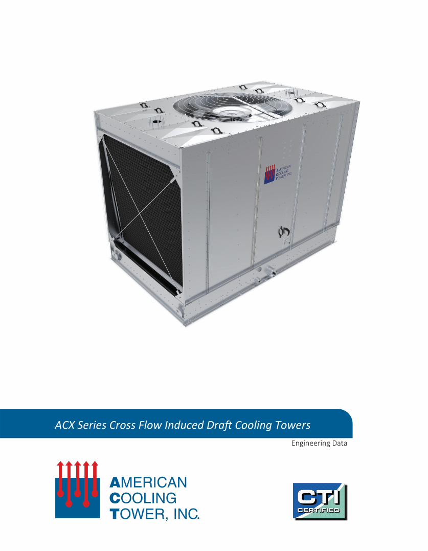
Overview
The ACX series induced draft cross flow cooling tower, manufactured by American Cooling Tower Inc., is a factory assembled cooling tower designed of heavy gauge steel construction which offers a diverse range of construction materials and accessories to accommodate virtually any project requirement.
Capacity
The ACX series cooling tower line offers 69 unique single cell models ranging from 102 to 1,074 nominal tons which have all been certified under CTI Standard 201. Through multiple cell configurations, American Cooling Tower offers added flexibility in design considerations to effectively manage footprint requirements while minimizing power consumption.
Proven Performance
The ACX series cooling tower has been offered through local representatives across the United States for the past several years with numerous installations in operation. These installations in conjunction with extensive factory testing allowed us to develop a cross flow unit which has documented performance and superior service life.
Technology & Partnerships
The ACX series design incorporates not just American Cooling Tower in house design team and engineering expertise, but also engaged our major component suppliers and utilized their extensive knowledge and experience. This process provided a method of verification across multiple designers, engineers, and companies to ensure that every aspect of the tower design is looked at and that the components chosen offer the best performance available in today’s marketplace.
Quality Control and Workmanship
American Cooling Tower has been providing custom designs for both packaged and field erect cooling towers for more than 30 years. Our team members are well experienced in the construction of cooling towers and have been thoroughly cross trained to maximize production efficiency and reliability. In conjunction with our highly experienced team members, American Cooling Tower also utilize a Total Quality Management (TQM) system when it comes to our purchasing, design, procurement, and quality control processes for all levels of operations. American Cooling Tower is able to closely monitor our entire system from start to finish to ensure the highest level of quality is always produced. Our TQM Process also include and encourage our customers, partners, and representatives to play an active role within our quality control processes so that all parties involved are able to actively participate within our management system.
Sustainability
American Cooling Tower continues their effort in utilizing sustainable and recycled materials within our product lines whenever it is feasible without sacrificing quality or performance. Through our steel and PVC materials alone, the ACX line is comprised of more than 70% recycled materials. While more must be done on a global scale, American Cooling Tower is continuing our own efforts to increase the percentage of recycled content within our products while also ensuring that our facilities are outfitted with the most energy efficient equipment, lighting, and tooling available.
AMERICAN COOLING TOWER INC. ACX SERIESComponents & Features
2www.AmericanCoolingTower.com
1
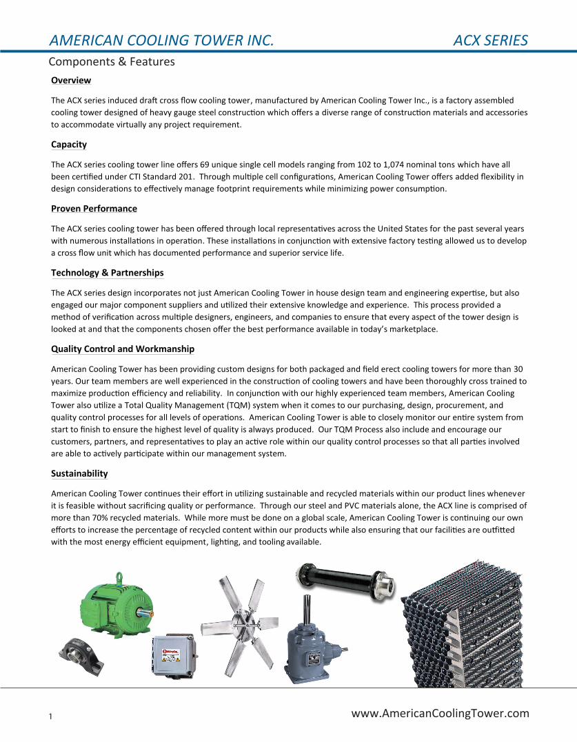
G235 galvanized steel orstainless steel 304/316 construction.
Large access doors locatedon both ends of unit withinternal walkway and optional elevated mechanical service platformsfor units over 14’ tall.
Powerband belt drive or right angle gear reducer mechanical systems.
Self-extinguishing PVC high performance cross flow fill media with integral louvers and eliminators.
Studded flange dual topinlets with optional singleside or bottom inlet connections available.
Removable hot water basincovers with ABS handles for ease of maintenance and inspection.
Removable OSHA compliant steel fan guards available in hotdipped galvanized (HDG) or stainless steel.
High grade marine aluminum 5052 constructionLow noise fan assembly, ‘SC’ fan with VTtip technology and resilient mount system for reduced sound levels and maximum operatingrange when used in conjunction with variable frequency drives. Dynamically balanced with adjustable pitch blades.
Internal mounted cooling tower duty, NEMA Premium efficient, MG1 Part 31 compliant motors suitable for operation with variable frequency drives, multi-voltage configuration. External motor mountconfigurations also available.
Standard connections include side outlet, make-up, drain, and overflow. Additional configurations available.
Giving you the ACTvantage you deserve!
The ACX Series offers a wide range of options and accessories along with multiple configurations to meet job specific demands.
Contact your representative today to learn more!
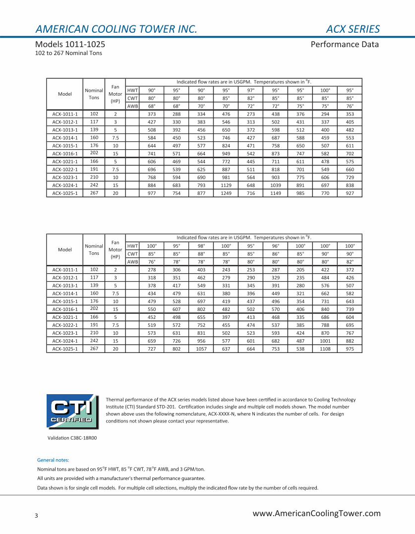
AMERICAN COOLING TOWER INC. ACX SERIESModels 1011-1025 Performance Data102 to 267 Nominal Tons
3 www.AmericanCoolingTower.com
HWT 90° 95° 90° 95° 97° 95° 95° 100° 95°CWT 80° 80° 80° 85° 82° 85° 85° 85° 85°AWB 68° 68° 70° 70° 72° 72° 75° 75° 76°
ACX-1011-1 102 2 373 288 334 476 273 438 376 294 353ACX-1012-1 117 3 427 330 383 546 313 502 431 337 405ACX-1013-1 139 5 508 392 456 650 372 598 512 400 482ACX-1014-1 160 7.5 584 450 523 746 427 687 588 459 553ACX-1015-1 176 10 644 497 577 824 471 758 650 507 611ACX-1016-1 202 15 741 571 664 949 542 873 747 582 702ACX-1021-1 166 5 606 469 544 772 445 711 611 478 575ACX-1022-1 191 7.5 696 539 625 887 511 818 701 549 660ACX-1023-1 210 10 768 594 690 981 564 903 775 606 729ACX-1024-1 242 15 884 683 793 1129 648 1039 891 697 838ACX-1025-1 267 20 977 754 877 1249 716 1149 985 770 927
HWT 100° 95° 98° 100° 95° 96° 100° 100° 100°CWT 85° 85° 88° 85° 85° 86° 85° 90° 90°AWB 76° 78° 78° 78° 80° 80° 80° 80° 82°
ACX-1011-1 102 2 278 306 403 243 253 287 205 422 372ACX-1012-1 117 3 318 351 462 279 290 329 235 484 426ACX-1013-1 139 5 378 417 549 331 345 391 280 576 507ACX-1014-1 160 7.5 434 479 631 380 396 449 321 662 582ACX-1015-1 176 10 479 528 697 419 437 496 354 731 643ACX-1016-1 202 15 550 607 802 482 502 570 406 840 739ACX-1021-1 166 5 452 498 655 397 413 468 335 686 604ACX-1022-1 191 7.5 519 572 752 455 474 537 385 788 695ACX-1023-1 210 10 573 631 831 502 523 593 424 870 767ACX-1024-1 242 15 659 726 956 577 601 682 487 1001 882ACX-1025-1 267 20 727 802 1057 637 664 753 538 1108 975
General notes:
Nominal tons are based on 95 oF HWT, 85 oF CWT, 78oF AWB, and 3 GPM/ton.
All units are provided with a manufacturer's thermal performance guarantee.
Data shown is for single cell models. For multiple cell selections, multiply the indicated �ow rate by the number of cells required.
Thermal performance of the ACX series models listed above have been certified in accordance to Cooling Technology Institute (CTI) Standard STD-201. Certification includes single and multiple cell models shown. The model number shown above uses the following nomenclature, ACX-XXXX-N, where N indicates the number of cells. For design conditions not shown please contact your representative.
Validation C38C-18R00
Nominal Tons
ModelFan
Motor (HP)
Indicated flow rates are in USGPM. Temperatures shown in oF.
ModelNominal
Tons
Fan Motor (HP)
Indicated flow rates are in USGPM. Temperatures shown in oF.
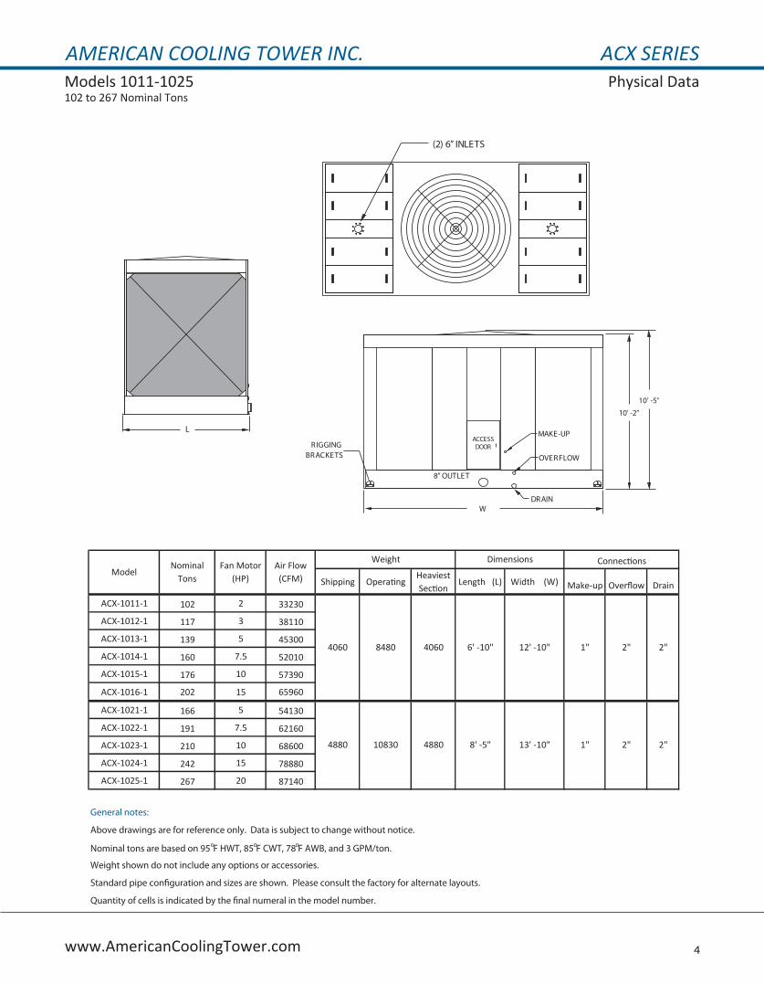
AMERICAN COOLING TOWER INC. ACX SERIESModels 1011-1025 Physical Data102 to 267 Nominal Tons
4www.AmericanCoolingTower.com
Shipping OperatingHeaviest Section
Length (L) Width (W) Make-up Overflow Drain
ACX-1011-1 102 2 33230
ACX-1012-1 117 3 38110
ACX-1013-1 139 5 45300
ACX-1014-1 160 7.5 52010
ACX-1015-1 176 10 57390
ACX-1016-1 202 15 65960
ACX-1021-1 166 5 54130
ACX-1022-1 191 7.5 62160
ACX-1023-1 210 10 68600
ACX-1024-1 242 15 78880
ACX-1025-1 267 20 87140
General notes:
Above drawings are for reference only. Data is subject to change without notice.
Nominal tons are based on 95oF HWT, 85oF CWT, 78oF AWB, and 3 GPM/ton.
Weight shown do not include any options or accessories.
Standard pipe con�guration and sizes are shown. Please consult the factory for alternate layouts.
Quantity of cells is indicated by the �nal numeral in the model number.
4880
1"
10830 4880 8' -5" 13' -10" 1"
Connections
2" 2"
2" 2"
ModelNominal
TonsFan Motor
(HP)Air Flow (CFM)
Weight Dimensions
4060 8480 4060 6' -10" 12' -10"
(2) 6” INLETS
L
W
10’ -2”
10’ -5”
OVERFLOW
DRAIN
8” OUTLET
MAKE-UPACCESSDOORRIGGING
BRACKETS

AMERICAN COOLING TOWER INC. ACX SERIESModels 1031-1046 Performance Data202 to 520 Nominal Tons
5 www.AmericanCoolingTower.com
HWT 90° 95° 90° 95° 97° 95° 95° 100° 95°CWT 80° 80° 80° 85° 82° 85° 85° 85° 85°AWB 68° 68° 70° 70° 72° 72° 75° 75° 76°
ACX-1031-1 202 5 727 571 657 918 544 849 735 583 693ACX-1032-1 231 7.5 834 655 753 1053 624 974 843 669 796ACX-1033-1 255 10 920 722 831 1162 689 1074 930 738 878ACX-1034-1 293 15 1057 829 954 1336 791 1235 1069 847 1008ACX-1035-1 324 20 1167 915 1053 1476 872 1364 1180 935 1113ACX-1036-1 349 25 1261 988 1138 1595 942 1474 1275 1010 1203ACX-1037-1 372 30 1344 1052 1212 1701 1003 1571 1358 1075 1281ACX-1038-1 411 40 1486 1163 1340 1882 1108 1738 1502 1188 1416ACX-1041-1 321 10 1148 911 1041 1437 871 1333 1161 932 1098ACX-1042-1 369 15 1321 1047 1196 1653 1000 1533 1335 1071 1263ACX-1043-1 408 20 1459 1157 1323 1828 1105 1695 1476 1183 1396ACX-1044-1 441 25 1578 1250 1430 1978 1194 1833 1596 1278 1509ACX-1045-1 470 30 1682 1332 1524 2110 1273 1955 1702 1363 1609ACX-1046-1 520 40 1862 1474 1687 2338 1408 2166 1884 1507 1781
HWT 100° 95° 98° 100° 95° 96° 100° 100° 100°CWT 85° 85° 88° 85° 85° 86° 85° 90° 90°AWB 76° 78° 78° 78° 80° 80° 80° 80° 82°
ACX-1031-1 202 5 553 605 786 489 507 571 417 822 730ACX-1032-1 231 7.5 635 694 902 561 582 655 478 943 837ACX-1033-1 255 10 700 766 994 618 642 722 527 1040 924ACX-1034-1 293 15 804 880 1143 710 737 829 605 1196 1061ACX-1035-1 324 20 887 971 1262 783 813 915 667 1321 1172ACX-1036-1 349 25 958 1049 1364 845 877 988 720 1427 1266ACX-1037-1 372 30 1020 1117 1454 900 934 1053 766 1521 1349ACX-1038-1 411 40 1127 1234 1608 994 1032 1163 846 1683 1492ACX-1041-1 321 10 886 964 1239 786 814 912 674 1294 1154ACX-1042-1 369 15 1018 1108 1425 903 935 1048 774 1489 1328ACX-1043-1 408 20 1124 1225 1576 998 1033 1158 855 1646 1468ACX-1044-1 441 25 1215 1324 1704 1078 1116 1251 923 1781 1587ACX-1045-1 470 30 1295 1411 1817 1148 1189 1334 983 1899 1693ACX-1046-1 520 40 1432 1561 2013 1270 1315 1475 1086 2104 1874
General notes:
Nominal tons are based on 95 oF HWT, 85oF CWT, 78oF AWB, and 3 GPM/ton.
All units are provided with a manufacturer's thermal performance guarantee.
Data shown is for single cell models. For multiple cell selections, multiply the indicated �ow rate by the number of cells required.
Validation C38C-18R00
Thermal performance of the ACX series models listed above have been certified in accordance to Cooling Technology Institute (CTI) Standard STD-201. Certification includes single and multiple cell models shown. The model number shown above uses the following nomenclature, ACX-XXXX-N, where N indicates the number of cells. For design conditions not shown please contact your representative.
ModelNominal
Tons
Fan Motor (HP)
Indicated flow rates are in USGPM. Temperatures shown in oF.
ModelNominal
Tons
Fan Motor (HP)
Indicated flow rates are in USGPM. Temperatures shown in oF.

AMERICAN COOLING TOWER INC. ACX SERIESModels 1031-1046 Physical Data202 to 520 Nominal Tons
6www.AmericanCoolingTower.com
Shipping OperatingHeaviest Section
Length (L) Width (W) Make-up Overflow Drain
ACX-1031-1 202 5 55430
ACX-1032-1 231 7.5 63590
ACX-1033-1 255 10 70120
ACX-1034-1 293 15 80540
ACX-1035-1 324 20 88900
ACX-1036-1 349 25 96000
ACX-1037-1 372 30 10260
ACX-1038-1 411 40 113000
ACX-1041-1 321 10 83840
ACX-1042-1 369 15 96370
ACX-1043-1 408 20 106500
ACX-1044-1 441 25 115110
ACX-1045-1 470 30 122700
ACX-1046-1 520 40 135750
General notes:
Above drawings are for reference only. Data is subject to change without notice.
Nominal tons are based on 95oF HWT, 85oF CWT, 78oF AWB, and 3 GPM/ton.
Weight shown do not include any options or accessories.
Standard pipe con�guration and sizes are shown. Please consult the factory for alternate layouts.
Quantity of cells is indicated by the �nal numeral in the model number.
8655 19230 8655 9' -10" 19' -6" 2" 3" 3"
ModelNominal
TonsFan Motor
(HP)Air Flow (CFM)
Weight Dimensions Connections
7430 16550 7430 8' -5" 17' -10" 1" 2" 2"
L
(2) 8” INLETS
W
11’ -11”
12’ -2“
OVERFLOW
DRAINACX-1031 TO 1038, 8” OUTLETACX-1041 TO 1046, 10” OUTLET
MAKE-UPACCESSDOORRIGGING
BRACKETS
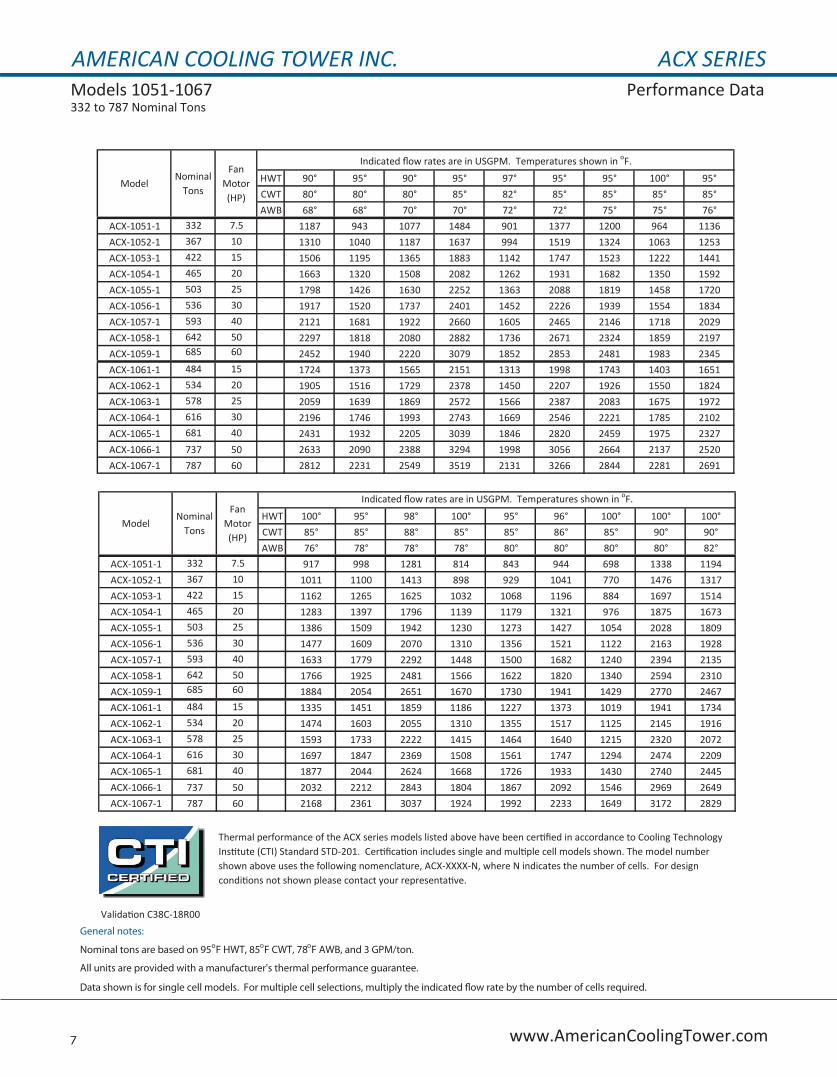
AMERICAN COOLING TOWER INC. ACX SERIESModels 1051-1067 Performance Data332 to 787 Nominal Tons
7 www.AmericanCoolingTower.com
HWT 90° 95° 90° 95° 97° 95° 95° 100° 95°CWT 80° 80° 80° 85° 82° 85° 85° 85° 85°AWB 68° 68° 70° 70° 72° 72° 75° 75° 76°
ACX-1051-1 332 7.5 1187 943 1077 1484 901 1377 1200 964 1136ACX-1052-1 367 10 1310 1040 1187 1637 994 1519 1324 1063 1253ACX-1053-1 422 15 1506 1195 1365 1883 1142 1747 1523 1222 1441ACX-1054-1 465 20 1663 1320 1508 2082 1262 1931 1682 1350 1592ACX-1055-1 503 25 1798 1426 1630 2252 1363 2088 1819 1458 1720ACX-1056-1 536 30 1917 1520 1737 2401 1452 2226 1939 1554 1834ACX-1057-1 593 40 2121 1681 1922 2660 1605 2465 2146 1718 2029ACX-1058-1 642 50 2297 1818 2080 2882 1736 2671 2324 1859 2197ACX-1059-1 685 60 2452 1940 2220 3079 1852 2853 2481 1983 2345ACX-1061-1 484 15 1724 1373 1565 2151 1313 1998 1743 1403 1651ACX-1062-1 534 20 1905 1516 1729 2378 1450 2207 1926 1550 1824ACX-1063-1 578 25 2059 1639 1869 2572 1566 2387 2083 1675 1972ACX-1064-1 616 30 2196 1746 1993 2743 1669 2546 2221 1785 2102ACX-1065-1 681 40 2431 1932 2205 3039 1846 2820 2459 1975 2327ACX-1066-1 737 50 2633 2090 2388 3294 1998 3056 2664 2137 2520ACX-1067-1 787 60 2812 2231 2549 3519 2131 3266 2844 2281 2691
HWT 100° 95° 98° 100° 95° 96° 100° 100° 100°CWT 85° 85° 88° 85° 85° 86° 85° 90° 90°AWB 76° 78° 78° 78° 80° 80° 80° 80° 82°
ACX-1051-1 332 7.5 917 998 1281 814 843 944 698 1338 1194ACX-1052-1 367 10 1011 1100 1413 898 929 1041 770 1476 1317ACX-1053-1 422 15 1162 1265 1625 1032 1068 1196 884 1697 1514ACX-1054-1 465 20 1283 1397 1796 1139 1179 1321 976 1875 1673ACX-1055-1 503 25 1386 1509 1942 1230 1273 1427 1054 2028 1809ACX-1056-1 536 30 1477 1609 2070 1310 1356 1521 1122 2163 1928ACX-1057-1 593 40 1633 1779 2292 1448 1500 1682 1240 2394 2135ACX-1058-1 642 50 1766 1925 2481 1566 1622 1820 1340 2594 2310ACX-1059-1 685 60 1884 2054 2651 1670 1730 1941 1429 2770 2467ACX-1061-1 484 15 1335 1451 1859 1186 1227 1373 1019 1941 1734ACX-1062-1 534 20 1474 1603 2055 1310 1355 1517 1125 2145 1916ACX-1063-1 578 25 1593 1733 2222 1415 1464 1640 1215 2320 2072ACX-1064-1 616 30 1697 1847 2369 1508 1561 1747 1294 2474 2209ACX-1065-1 681 40 1877 2044 2624 1668 1726 1933 1430 2740 2445ACX-1066-1 737 50 2032 2212 2843 1804 1867 2092 1546 2969 2649ACX-1067-1 787 60 2168 2361 3037 1924 1992 2233 1649 3172 2829
General notes:
Nominal tons are based on 95oF HWT, 85oF CWT, 78oF AWB, and 3 GPM/ton.
All units are provided with a manufacturer's thermal performance guarantee.
Data shown is for single cell models. For multiple cell selections, multiply the indicated �ow rate by the number of cells required.
Validation C38C-18R00
Thermal performance of the ACX series models listed above have been certified in accordance to Cooling Technology Institute (CTI) Standard STD-201. Certification includes single and multiple cell models shown. The model number shown above uses the following nomenclature, ACX-XXXX-N, where N indicates the number of cells. For design conditions not shown please contact your representative.
ModelNominal
Tons
Fan Motor (HP)
Indicated flow rates are in USGPM. Temperatures shown in oF.
ModelNominal
Tons
Fan Motor (HP)
Indicated flow rates are in USGPM. Temperatures shown in oF.
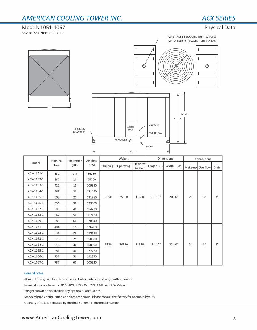
AMERICAN COOLING TOWER INC. ACX SERIESModels 1051-1067 Physical Data332 to 787 Nominal Tons
8www.AmericanCoolingTower.com
Shipping OperatingHeaviest Section
Length (L) Width (W) Make-up Overflow Drain
ACX-1051-1 332 7.5 86280
ACX-1052-1 367 10 95700
ACX-1053-1 422 15 109990
ACX-1054-1 465 20 121490
ACX-1055-1 503 25 131280
ACX-1056-1 536 30 139900
ACX-1057-1 593 40 154730
ACX-1058-1 642 50 167430
ACX-1059-1 685 60 178640
ACX-1061-1 484 15 126200
ACX-1062-1 534 20 139410
ACX-1063-1 578 25 150680
ACX-1064-1 616 30 160600
ACX-1065-1 681 40 177720
ACX-1066-1 737 50 192370
ACX-1067-1 787 60 205320
General notes:
Above drawings are for reference only. Data is subject to change without notice.
Nominal tons are based on 95oF HWT, 85oF CWT, 78oF AWB, and 3 GPM/ton.
Weight shown do not include any options or accessories.
Standard pipe con�guration and sizes are shown. Please consult the factory for alternate layouts.
Quantity of cells is indicated by the �nal numeral in the model number.
3" 3"
3" 3"13530
11650 25300 11650 11' -10" 20' -6" 2"
30610 13530 13' -10" 22' -0" 2"
ModelNominal
TonsFan Motor
(HP)Air Flow (CFM)
Weight Dimensions Connections
L
(2) 8” INLETS (MODEL 1051 TO 1059)(2) 10” INLETS (MODEL 1061 TO 1067)
W
11’ -11”
12’ -2”
OVERFLOW
DRAIN
10” OUTLET
MAKE-UPACCESSDOORRIGGING
BRACKETS
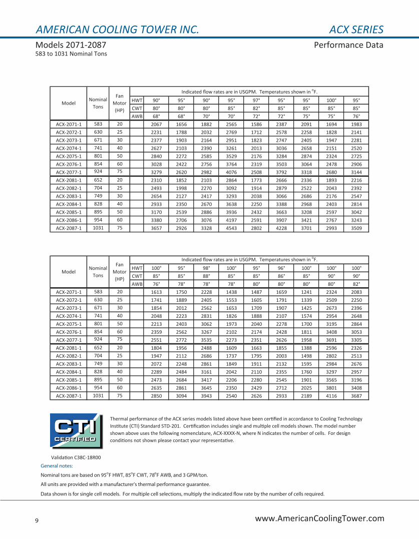
AMERICAN COOLING TOWER INC. ACX SERIESModels 2071-2087 Performance Data583 to 1031 Nominal Tons
9 www.AmericanCoolingTower.com
HWT 90° 95° 90° 95° 97° 95° 95° 100° 95°CWT 80° 80° 80° 85° 82° 85° 85° 85° 85°AWB 68° 68° 70° 70° 72° 72° 75° 75° 76°
ACX-2071-1 583 20 2067 1656 1882 2565 1586 2387 2091 1694 1983ACX-2072-1 630 25 2231 1788 2032 2769 1712 2578 2258 1828 2141ACX-2073-1 671 30 2377 1903 2164 2951 1823 2747 2405 1947 2281ACX-2074-1 741 40 2627 2103 2390 3261 2013 3036 2658 2151 2520ACX-2075-1 801 50 2840 2272 2585 3529 2176 3284 2874 2324 2725ACX-2076-1 854 60 3028 2422 2756 3764 2319 3503 3064 2478 2906ACX-2077-1 924 75 3279 2620 2982 4076 2508 3792 3318 2680 3144ACX-2081-1 652 20 2310 1852 2103 2864 1773 2666 2336 1893 2216ACX-2082-1 704 25 2493 1998 2270 3092 1914 2879 2522 2043 2392ACX-2083-1 749 30 2654 2127 2417 3293 2038 3066 2686 2176 2547ACX-2084-1 828 40 2933 2350 2670 3638 2250 3388 2968 2403 2814ACX-2085-1 895 50 3170 2539 2886 3936 2432 3663 3208 2597 3042ACX-2086-1 954 60 3380 2706 3076 4197 2591 3907 3421 2767 3243ACX-2087-1 1031 75 3657 2926 3328 4543 2802 4228 3701 2993 3509
HWT 100° 95° 98° 100° 95° 96° 100° 100° 100°CWT 85° 85° 88° 85° 85° 86° 85° 90° 90°AWB 76° 78° 78° 78° 80° 80° 80° 80° 82°
ACX-2071-1 583 20 1613 1750 2228 1438 1487 1659 1241 2324 2083ACX-2072-1 630 25 1741 1889 2405 1553 1605 1791 1339 2509 2250ACX-2073-1 671 30 1854 2012 2562 1653 1709 1907 1425 2673 2396ACX-2074-1 741 40 2048 2223 2831 1826 1888 2107 1574 2954 2648ACX-2075-1 801 50 2213 2403 3062 1973 2040 2278 1700 3195 2864ACX-2076-1 854 60 2359 2562 3267 2102 2174 2428 1811 3408 3053ACX-2077-1 924 75 2551 2772 3535 2273 2351 2626 1958 3691 3305ACX-2081-1 652 20 1804 1956 2488 1609 1663 1855 1388 2596 2326ACX-2082-1 704 25 1947 2112 2686 1737 1795 2003 1498 2802 2513ACX-2083-1 749 30 2072 2248 2861 1849 1911 2132 1595 2984 2676ACX-2084-1 828 40 2289 2484 3161 2042 2110 2355 1760 3297 2957ACX-2085-1 895 50 2473 2684 3417 2206 2280 2545 1901 3565 3196ACX-2086-1 954 60 2635 2861 3645 2350 2429 2712 2025 3801 3408ACX-2087-1 1031 75 2850 3094 3943 2540 2626 2933 2189 4116 3687
General notes:
Nominal tons are based on 95oF HWT, 85oF CWT, 78oF AWB, and 3 GPM/ton.
All units are provided with a manufacturer's thermal performance guarantee.
Data shown is for single cell models. For multiple cell selections, multiply the indicated �ow rate by the number of cells required.
Thermal performance of the ACX series models listed above have been certified in accordance to Cooling Technology Institute (CTI) Standard STD-201. Certification includes single and multiple cell models shown. The model number shown above uses the following nomenclature, ACX-XXXX-N, where N indicates the number of cells. For design conditions not shown please contact your representative.
Validation C38C-18R00
ModelNominal
Tons
Fan Motor (HP)
Indicated flow rates are in USGPM. Temperatures shown in oF.
ModelNominal
Tons
Fan Motor (HP)
Indicated flow rates are in USGPM. Temperatures shown in oF.
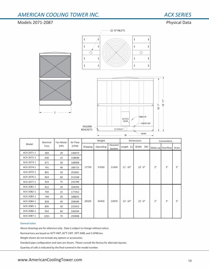
AMERICAN COOLING TOWER INC. ACX SERIESModels 2071-2087 Physical Data
10www.AmericanCoolingTower.com
Shipping OperatingHeaviest Section
Length (L) Width (W) Make-up Overflow Drain
ACX-2071-1 583 20 146973
ACX-2072-1 630 25 158698
ACX-2073-1 671 30 168998
ACX-2074-1 741 40 186725
ACX-2075-1 801 50 201841
ACX-2076-1 854 60 212168
ACX-2077-1 924 75 232789
ACX-2081-1 652 20 164293
ACX-2082-1 704 25 177352
ACX-2083-1 749 30 188835
ACX-2084-1 828 40 208589
ACX-2085-1 895 50 225453
ACX-2086-1 954 60 240294
ACX-2087-1 1031 75 259908
General notes:
Above drawings are for reference only. Data is subject to change without notice.
Nominal tons are based on 95oF HWT, 85oF CWT, 78oF AWB, and 3 GPM/ton.
Weight shown do not include any options or accessories.
Standard pipe con�guration and sizes are shown. Please consult the factory for alternate layouts.
Quantity of cells is indicated by the �nal numeral in the model number.
17750 37630 11450 11' -10" 22' -0" 2" 3" 3"
20105 43450 12870 13' -10" 22' -0" 2" 3" 3"
ModelNominal
TonsFan Motor
(HP)Air Flow (CFM)
Weight Dimensions Connections
(2) 10” INLETS
L
18’-7” 18’-11”
W
RIGGINGBRACKETS
ACCESSDOOR
MAKE-UP
OVERFLOW
DRAIN
12”OUTLET

AMERICAN COOLING TOWER INC. ACX SERIESModels 2091-2107 Performance Data630 to 1074 Nominal Tons
11 www.AmericanCoolingTower.com
HWT 90° 95° 90° 95° 97° 95° 95° 100° 95°CWT 80° 80° 80° 85° 82° 85° 85° 85° 85°AWB 68° 68° 70° 70° 72° 72° 75° 75° 76°
ACX-2091-1 630 20 2229 1788 2030 2764 1714 2573 2255 1829 2140ACX-2092-1 679 25 2404 1929 2191 2981 1849 2775 2434 1973 2310ACX-2093-1 723 30 2560 2053 2332 3173 1968 2954 2590 2100 2458ACX-2094-1 798 40 2852 2266 2574 3504 2172 3262 2859 2318 2714ACX-2095-1 862 50 3052 2446 2780 3786 2345 3524 3089 2503 2931ACX-2096-1 918 60 3252 2606 2961 4034 2498 3755 3291 2666 3123ACX-2097-1 993 75 3515 2816 3201 4362 2699 4060 3558 2881 3376ACX-2101-1 680 20 2408 1932 2193 2985 1852 2779 2436 1976 2312ACX-2102-1 734 25 2598 2085 2367 3221 1997 2998 2630 2132 2495ACX-2103-1 782 30 2765 2219 2519 3429 2126 3192 2799 2269 2656ACX-2104-1 863 40 3054 2449 2782 3786 2347 3525 3091 2505 2932ACX-2105-1 932 50 3299 2645 3005 4093 2535 3809 3340 2706 3168ACX-2106-1 993 60 3516 2818 3202 4363 2700 4060 3559 2883 3376ACX-2107-1 1074 75 3803 3046 3462 4718 2918 4391 3849 3116 3650
HWT 100° 95° 98° 100° 95° 96° 100° 100° 100°CWT 85° 85° 88° 85° 85° 86° 85° 90° 90°AWB 76° 78° 78° 78° 80° 80° 80° 80° 82°
ACX-2091-1 630 20 1743 1890 2403 1556 1608 1793 1344 2506 2247ACX-2092-1 679 25 1881 2038 2593 1679 1735 1935 1449 2703 2425ACX-2093-1 723 30 2001 2170 2760 1787 1846 2058 1543 2878 2581ACX-2094-1 798 40 2208 2395 3047 1971 2037 2271 1701 3177 2849ACX-2095-1 862 50 2385 2587 3292 2129 2200 2453 1837 3433 3078ACX-2096-1 918 60 2540 2755 3507 2266 2342 2613 1956 3659 3280ACX-2097-1 993 75 2745 2978 3792 2449 2531 2824 2113 3955 3546ACX-2101-1 680 20 1883 2042 2595 1680 1736 1936 1451 2706 2426ACX-2102-1 734 25 2032 2203 2800 1814 1874 2089 1566 2919 2619ACX-2103-1 782 30 2163 2345 2981 1930 1994 2224 1666 3108 2788ACX-2104-1 863 40 2387 2589 3291 2130 2202 2455 1839 3432 3078ACX-2105-1 932 50 2579 2797 3557 2301 2378 2652 1985 3709 3327ACX-2106-1 993 60 2747 2980 3791 2450 2532 2825 2114 3953 3546ACX-2107-1 1074 75 2969 3220 4099 2648 2737 3054 2284 4278 3835
General notes:
Nominal tons are based on 95oF HWT, 85oF CWT, 78oF AWB, and 3 GPM/ton.
All units are provided with a manufacturer's thermal performance guarantee.
Data shown is for single cell models. For multiple cell selections, multiply the indicated �ow rate by the number of cells required.
Validation C38C-18R00
Thermal performance of the ACX series models listed above have been certified in accordance to Cooling Technology Institute (CTI) Standard STD-201. Certification includes single and multiple cell models shown. The model number shown above uses the following nomenclature, ACX-XXXX-N, where N indicates the number of cells. For design conditions not shown please contact your representative.
ModelNominal
Tons
Fan Motor (HP)
Indicated flow rates are in USGPM. Temperatures shown in oF.
ModelNominal
Tons
Fan Motor (HP)
Indicated flow rates are in USGPM. Temperatures shown in oF.
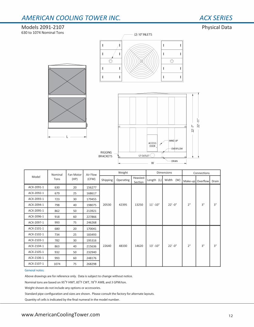
AMERICAN COOLING TOWER INC. ACX SERIESModels 2091-2107 Physical Data630 to 1074 Nominal Tons
12www.AmericanCoolingTower.com
Shipping OperatingHeaviest Section
Length (L) Width (W) Make-up Overflow Drain
ACX-2091-1 630 20 156277
ACX-2092-1 679 25 168617
ACX-2093-1 723 30 179455
ACX-2094-1 798 40 198075
ACX-2095-1 862 50 213921
ACX-2096-1 918 60 227866
ACX-2097-1 993 75 246268
ACX-2101-1 680 20 170041
ACX-2102-1 734 25 183493
ACX-2103-1 782 30 195316
ACX-2104-1 863 40 215636
ACX-2105-1 932 50 232940
ACX-2106-1 993 60 248176
ACX-2107-1 1074 75 268298
General notes:
Above drawings are for reference only. Data is subject to change without notice.
Nominal tons are based on 95oF HWT, 85oF CWT, 78oF AWB, and 3 GPM/ton.
Weight shown do not include any options or accessories.
Standard pipe con�guration and sizes are shown. Please consult the factory for alternate layouts.
Quantity of cells is indicated by the �nal numeral in the model number.
3" 3"22640 48330 14620 13' -10" 22' -0" 2"
ModelNominal
TonsFan Motor
(HP)Air Flow (CFM)
Weight Dimensions Connections
20530 42395 13250 11' -10" 22' -0" 2" 3" 3"
(2) 10” INLETS
L
22’-7” 22’-11”
W
RIGGINGBRACKETS
ACCESSDOOR
MAKE-UP
OVERFLOW
DRAIN
12”OUTLET
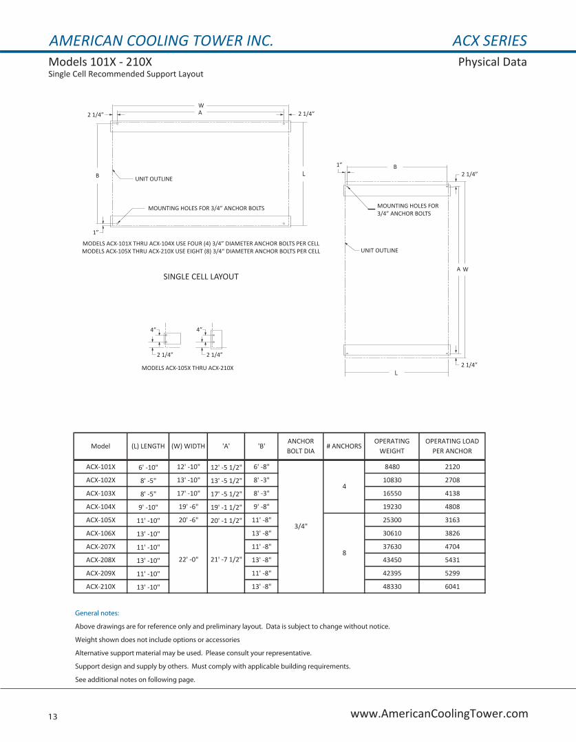
AMERICAN COOLING TOWER INC. ACX SERIESModels 101X - 210X Physical DataSingle Cell Recommended Support Layout
13 www.AmericanCoolingTower.com
ACX-101X 6' -10" 12' -10" 12' -5 1/2" 6' -8" 8480 2120
ACX-102X 8' -5" 13' -10" 13' -5 1/2" 8' -3" 10830 2708
ACX-103X 8' -5" 17' -10" 17' -5 1/2" 8' -3" 16550 4138
ACX-104X 9' -10" 19' -6" 19' -1 1/2" 9' -8" 19230 4808
ACX-105X 11' -10" 20' -6" 20' -1 1/2" 11' -8" 25300 3163
ACX-106X 13' -10" 13' -8" 30610 3826
ACX-207X 11' -10" 11' -8" 37630 4704
ACX-208X 13' -10" 13' -8" 43450 5431
ACX-209X 11' -10" 11' -8" 42395 5299
ACX-210X 13' -10" 13' -8" 48330 6041
General notes:
Above drawings are for reference only and preliminary layout. Data is subject to change without notice.
Weight shown does not include options or accessories
Alternative support material may be used. Please consult your representative.
Support design and supply by others. Must comply with applicable building requirements.
See additional notes on following page.
4
8
3/4"
21' -7 1/2"22' -0"
ANCHOR BOLT DIA
# ANCHORSOPERATING
WEIGHTOPERATING LOAD
PER ANCHORModel (L) LENGTH (W) WIDTH 'A' 'B'
4”
2 1/4” 2 1/4”
4”
MODELS ACX-105X THRU ACX-210X
MODELS ACX-101X THRU ACX-104X USE FOUR (4) 3/4” DIAMETER ANCHOR BOLTS PER CELLMODELS ACX-105X THRU ACX-210X USE EIGHT (8) 3/4“ DIAMETER ANCHOR BOLTS PER CELL
SINGLE CELL LAYOUT
2 1/4” 2 1/4”WA
1”
B LUNIT OUTLINE
MOUNTING HOLES FOR 3/4” ANCHOR BOLTS
2 1/4”
2 1/4”
WA
1” B
L
UNIT OUTLINE
MOUNTING HOLES FOR3/4” ANCHOR BOLTS
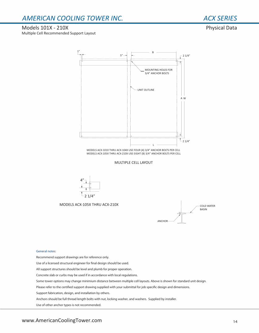
AMERICAN COOLING TOWER INC. ACX SERIESModels 101X - 210X Physical DataMultiple Cell Recommended Support Layout
14www.AmericanCoolingTower.com
General notes:
Recommend support drawings are for reference only.
Use of a licensed structural engineer for �nal design should be used.
All support structures should be level and plumb for proper operation.
Concrete slab or curbs may be used if in accordance with local regulations.
Some tower options may change minimium distance between multiple cell layouts. Above is shown for standard unit design.
Please refer to the certi�ed support drawing supplied with your submittal for job speci�c design and dimensions.
Support fabrication, design, and installation by others.
Anchors should be full thread length bolts with nut, locking washer, and washers. Supplied by installer.
Use of other anchor types is not recommended.
ANCHOR
COLD WATERBASIN
4”
2 1/4”
MODELS ACX-105X THRU ACX-210X
MULTIPLE CELL LAYOUT
MODELS ACX-101X THRU ACX-104X USE FOUR (4) 3/4” ANCHOR BOLTS PER CELLMODELS ACX-105X THRU ACX-210X USE EIGHT (8) 3/4“ ANCHOR BOLTS PER CELL
2 1/4”
2 1/4”
WA
1” B
L
UNIT OUTLINE
MOUNTING HOLES FOR3/4” ANCHOR BOLTS
5”
AMERICAN COOLING TOWER INC. ACX SERIESSample Specification
15 www.AmericanCoolingTower.com
GENERAL 1.0 SELECTION Furnish American Cooling Tower model ACX- cooling tower(s). The ACX series cooling tower is a factory assembled, induced draft, axial fan, cross flow cooling tower with vertical air discharge. The cooling tower’s overall dimensions shall not exceed in length X in width X in height. Each cooling tower shall consist of cell(s). 1.1 PERFORMANCE The cooling tower(s) shall be designed to provide USGPM of total cooling capacity based on an entering hot water temperature of oF with a leaving cold water temperature of oF and an entering ambient wet-bulb temperature of oF. The unit selected shall have had its published ratings and thermal performance tested and certified in accordance with CTI standard 201. In addition the CTI STD-201 certification the cooling tower shall be supplied with a manufacturer’s thermal performance guarantee that is backed by the CTI ATC-105 field acceptance test code. Units shall also comply with CTI ATC-128 for cooling tower sound performance and meet or exceed ASHRAE 90.1 energy efficiency standards. MATERIALS OF CONSTRUCTION 2.0 STRUCTURE The cooling tower shall be constructed out of a heavy-gauge steel design and engineered for maximum strength, durability, and service life. All cooling tower seams shall be sealed to provide watertight joints. The unit’s standard construction shall be designed for a maximum 60 PSF wind load or 1.0g seismic force. For locations which exceed these amounts, the unit will be supplied with Structural Enhancement ‘SE’ construction package which includes additional anchorage and internal bracing and permit the cooling tower to handle a maximum wind load of 145 PSF or 5.12g seismic rating. All serviceable platforms, ladders, and landings shall be designed for a maximum 60 PSF live load or 300 pound concentrated load. Units shall exceed NFPA 2.14 requirements for fire safety and not require the use of external sprinkler systems. 2.1 COLD WATER BASIN The cold water basin section shall be constructed of G-235 galvanized steel in accordance with ASTM A653/A653M to provide maximum durability and excellent resistance to rust and corrosion. G-235 designation represents that an average coating thickness of 2.35 ounces of zinc per square foot shall be applied to the steel surfaces. Units which utilize a designation less than G-235 shall not be acceptable. The cold water basin shall be designed with a tiered configuration allowing for reduced water volume to be retained in the basin which shall lower operating weight, and allow for easier maintenance. The cold water basin section shall include standard piping points of connection for the overflow, make-up, drain, and outlet connections. Outlet connection shall be beveled for weld and grooved for mechanical coupling (flanged to accept an ASME B16.5 Class 150 type flange). On multiple cell units an internal equalization system (external equalizer connections for field piping) shall be provided and allows isolation of individual cells for maintenance, and servicing.
2.1a (OPTION) TYPE SERIES 304 (316) STAINLESS STEEL COLD WATER BASIN WITH TRITEK SEAM PROTECTION The cold water basin section shall be constructed of stainless steel 304 (316) steel to provide superior service life, durability and excellent resistance to rust and corrosion. The cold water basin shall be designed with a tiered configuration allowing for reduced water volume to be retained in the basin which shall lower operating weight, and allow for easier maintenance. Stainless steel grade less than 304 (316) shall not be acceptable. The stainless steel basin seams shall be provided with the TRITEK protection system which incorporates a multi-layered seam sealant system guaranteed to be leak free for a period of five (5) years. The TRITEK system utilizes sealer tape installed within the seam joint and two layers of factory applied protection along the interior surface of the seam. Welded basin seams that are guaranteed to be leak free for five (5) years are an acceptable substitute. The cold water basin section shall include standard piping points of connection for the overflow, make-up, drain, and outlet connections. Outlet connection shall be beveled for weld and grooved for mechanical coupling (flanged to accept an ASME B16.5 Class 150 type flange). On multiple cell units an internal equalization system (external equalizer connections for field piping) shall be provided and allows isolation of individual cells for maintenance, and servicing.
2.1b (OPTION) TYPE 304 (316) STAINLESS STEEL COLD WATER BASIN - WELDED BASIN SEAMS The cold water basin section shall be constructed of stainless steel 304 (316) steel to provide superior service life, durability and superior resistance to rust and corrosion. The cold water basin shall be designed with a tiered configuration that is sloped to allow for reduced water volume to be retained in the basin which shall lower operating weight, and promote positive drainage of the unit. Stainless steel grade less than 304 (316) shall not be acceptable. The stainless steel basin seams shall be provided with continuous welded basin seams which shall be guaranteed to be leak free for a period of five (5) years. Bolted basins shall not be acceptable. The cold water basin section shall include standard piping points of connection for the overflow, make-up, drain, and outlet connections. Outlet connection shall be (beveled for weld and grooved for mechanical coupling (an ASME B16.5 Class 150 Flange). On multiple cell units, an internal equalization system (external field equalizer connections) shall be provided and allow isolation of individual cells for maintenance, and servicing.
AMERICAN COOLING TOWER INC. ACX SERIESSample Specification
16www.AmericanCoolingTower.com
2.2 CASING PANELS The casing panels shall be constructed of G-235 (ASTM A653/A653M) galvanized steel to maximize the life of the cooling tower and minimize rust and corrosion. The casing panels shall be designed with heavy-gauge steel that incorporates flanged edges with rounded corners for maximum strength and durability. The panels shall be fastened to the cooling tower structure with all seams sealed to provide watertight joints. 2.2 (OPTION) STAINLESS STEEL 304 (316) STAINLESS STEEL CASING PANELS
The casing shall be constructed of series 304 (316) stainless steel to maximize the life of the cooling tower and provide superior protection against rust and corrosion. The casing panels shall be designed with heavy-gauge steel that incorporates flanged edges with rounded corners for maximum strength and durability. The panels shall be fastened to the cooling tower structure utilizing stainless steel fasteners of the same grade as the panels. All seams shall be sealed to provide watertight joints. Self-tapping fasteners shall not be accepted.
2.3 INTERNAL SUPPORT MEMBERS The cooling tower shall be constructed of heavy-gauge G-235 (ASTM A653/A653M) galvanized steel for maximum strength and durability. All weight bearing support pieces will be fabricated from heavy gauge steel to ensure structural integrity of the unit throughout its service life. All supports will be fastened with galvanized hardware and fasteners. 2.3a (OPTION) STAINLESS STEEL 304 (316) INTERNAL SUPPORT MEMBERS
The cooling tower shall be constructed of heavy-gauge stainless steel 304 (316) steel to provide superior service life, durability and excellent resistance to rust and corrosion. All weight bearing support pieces will be fabricated from heavy gauge steel to ensure structural integrity of the unit throughout its service life. All supports will be fastened with stainless steel hardware.
MECHANICAL COMPONENTS 3.0 MECHANICAL BELT DRIVE SYSTEM The fan drive system shall be belt driven consisting of a multi-groove, solid back Banded V-belt with taper lock sheaves designed with a minimum service factor of 1.5 and designed to be utilized in conjunction with a variable frequency drive. Multiple single belt systems shall not be accepted. Large diameter driven sheaves shall be constructed of lightweight aluminum alloy for corrosion protection. 3.0a (OPTION) MECHANICAL GEAR DRIVE SYSTEM
The fan drive system shall be a right angle gear driven design consisting of a right angle gear drive assembly which meets AGMA and CTI standards. A high efficiency close coupler (on internally mounted motors) or composite drive shaft with stainless steel couplings (externally mounted motors) shall be designed for maximum transmission efficiency and performance. Gear driven mechanical systems shall be designed for a minimum 2.0 service factor and suitable for operation in conjunction with a variable frequency drive.
3.1 FAN MOTOR(S) HP NEMA Premium Efficiency totally enclosed fan cooled (T.E.F.C.) ball bearing fan motor(s) with a minimum 1.25 service factor shall be furnished and suitable for cooling tower service on 208-230/460 volts, 60 hertz, 3 phase. The fan motor shall be designed in accordance with MGI, part 31 suitable for inverter duty operation or in conjunction with a variable frequency drive. Motors shall be tested in accordance with IEEE 112, method B and efficiency values shall be certified by UL. The motor shall be designed specifically for use in cooling tower environments. Motor construction shall be provided with an interior and exterior epoxy coating to provide maximum protection against corrosion. The motor(s) shall be installed on an adjustable base for servicing and maintenance. A protective hinged cover shall shield externally mounted motors to protect them from the weather and to restrict accessibility to the rotating shaft, sheave, and belts for safety. When a gear drive system is chosen, the fan motors shall be mounted horizontally on a fixed motor base and shall be either close coupled internally or when mounted externally shall be provided with a removable shaft and coupling guard. 3.2 LOW NOISE ‘SC’ FAN WITH VT TIP TECHNOLOGY Fan(s) shall be low noise wide chord, axial propeller, adjustable pitch type, marine grade aluminum design, that are dynamically balanced. The fan(s) shall be supplied and installed by the manufacturer prior to shipping maintaining a strict tip clearance for maximum efficiency. Fans shall be constructed of 5052 high grade marine alloy aluminum for maximum protection against rust and corrosion. Fan blades shall be shall be designed with a resilient mounting system to eliminate the need to lockout variable frequency drive ranges. The fan(s) shall incorporate velocity tips for reduced sound. Fans constructed of galvanized steel or fixed pitch type shall not be acceptable. The fan shall be located within a fan stack that shall be designed out of G-235 galvanized steel (stainless steel type 304 (316)) and shall include a hot dipped galvanized steel (stainless steel) OSHA compliant fan guard that is securely fastened to the fan stack by fasteners during operation and can be removed for inspection or servicing.
AMERICAN COOLING TOWER INC. ACX SERIESSample Specification
17 www.AmericanCoolingTower.com
3.2a (OPTION) SUPER LOW NOISE ‘EC’ FAN WITH VE TIP TECHNOLOGY
Fan(s) shall be extended chord super low noise, axial propeller, adjustable pitch type, marine grade aluminum design that are dynamically balanced. The fan(s) shall be supplied and installed by the manufacturer prior to shipping maintaining a strict tip clearance for maximum efficiency. Fans shall be constructed of 5052 high grade marine alloy aluminum for maximum protection against rust and corrosion. Fan blades shall be shall be designed with a resilient mounting system to eliminate the need to lockout variable frequency drive ranges. The fan(s) shall incorporate velocity edge for reduced sound. Fans constructed of galvanized steel or fixed pitch type shall not be acceptable. The fan shall be located within a fan stack that shall be designed out of G-235 galvanized steel (stainless steel type 304 (316)) and shall include a hot dipped galvanized steel (stainless steel) OSHA compliant fan guard that is securely fastened to the fan stack by fasteners during operation and can be removed for inspection or servicing. The cooling tower’s fan stack shall be increased to accommodate the extended chord fan design for maximum efficiency.
3.3 BEARINGS Fan shaft bearings shall be heavy duty self-aligning ball type with self-locking collars and lube lines that extend to the outside of the unit near the access door for servicing. Bearings shall be designed for a minimum L10 life of 100,000 hours minimum and shall be guaranteed for a period of five (5) years under the mechanical warranty.
3.3a (OPTION) RIGHT ANGLE GEAR DRIVE The cooling tower shall be designed with a right angle gear drive which exceeds AGMA and CTI standards. Right angle gear drives shall be constructed of a heavy duty rigid case which is epoxy coated for maximum protection against rust and corrosion and designed to absorb internal and external loads with minimum deflection. The spiral bevel gears are precision machined from high grade alloy steel, case hardened, and lapped in pairs for maximum durability and efficiency. The gear drives internal bearings shall be designed for a 100,000 hour L10 life. Lubrication of the gear drive occurs by way of an internal slinger which incorporates a low speed function to eliminate minimum speed requirements and is suitable for operation in conjunction with a variable frequency drive. The gear drive utilizes a permanently mounted oil sight level gauge and is provided with an oil fill line and a drain line for servicing. Oil fill line shall be ran to the exterior of the cooling tower near the access door for servicing. Units which do not provide low speed options or extended oil fill lines shall not be accepted.
3.4 MECHANICAL WARRANTY Cooling tower fan drive components shall be covered by a five (5) year complete mechanical warranty. Drive components protected by this warranty shall include the fans, bearings, fan shafts, belts, sheaves, bushings, and fan motors. WATER DISTRIBUTION SYSTEM 4.1 WATER DISTRIBUTION SYSTEM The hot water distribution basins shall be constructed of heavy gauge G235 (ASTM A653/A653M) galvanized steel materials and shall be open gravity type for easy cleaning and maintenance. The basins must be accessible from outside the unit and serviceable during tower operation. The hot water distribution basins shall be designed with top inlet studded flange connections located above each fill region of the cooling tower. The studded connections will be supplied with flow control valves for water balancing and connection to field piping. Distribution covers shall be constructed out of identical materials and shall be removable during tower operation for inspection and servicing of the hot water basins. Plastic or FRP covers shall not be accepted.
4.1a (OPTION) STAINLESS STEEL 304 (316) WATER DISTRIBUTION SYSTEM
The hot water distribution basins shall be constructed of heavy gauge stainless steel 304(316) materials and shall be open gravity type for easy cleaning and maintenance. The basins must be accessible from outside the unit and serviceable during tower operation. The hot water distribution basins shall be designed with top inlet studded flange connections located above each fill region of the cooling tower. The studded connections will be supplied with flow control valves for water balancing and connection to field piping. Distribution covers shall be constructed out of identical materials and shall be removable during tower operation for inspection and servicing of the hot water basins. Plastic or FRP covers shall not be accepted.
4.2 (OPTION) SINGLE POINT INLET CONNECTION – SIDE INLET CONNECTION The cooling tower inlet piping shall be a single point connection type that is designed with factory installed piping to deliver balanced water flow to the hot water basins and simplify field piping of the cooling tower. The single inlet connection shall be side oriented with a beveled for weld and grooved connection type for mechanical coupling (flanged to accept an ASME B16.5 Class 150 type flange).
AMERICAN COOLING TOWER INC. ACX SERIESSample Specification
18www.AmericanCoolingTower.com
4.2 (OPTION) SINGLE POINT INLET CONNECTION – SIDE INLET CONNECTION The cooling tower inlet piping shall be a single point connection type that is designed with factory installed piping to deliver balanced water flow to the hot water basins and simplify field piping of the cooling tower. The single inlet connection shall be side oriented with a beveled for weld and grooved connection type for mechanical coupling (flanged to accept an ASME B16.5 Class 150 type flange). 4.2a(OPTION) SINGLE POINT INLET CONNECTION – BOTTOM INLET CONNECTION
The cooling tower inlet piping shall be a single point connection type that is designed with factory installed piping to deliver balanced water flow to the hot water basins and simplify field piping of the cooling tower. The single inlet connection shall be bottom oriented type flat face flange designed to accept an ASME B16.5 Class 150 type flange.
THERMAL COMPONENTS 5.1 FILL MEDIA The cooling tower fill shall be PVC (Polyvinyl Chloride) of herring bone design for maximum heat transfer. The PVC fill shall be self-extinguishing for fire resistance with a flame spread rating of 5 per ASTM E84-81a. It shall also be resistant to rot, decay and biological attack. The fill shall be able to withstand continuous hot water temperatures up to 140°F. Fill media shall be supported by fiberglass reinforced polyester FRP bottom support system designed to elevate the fill media off of the floor of the basin and permit water circulation while preventing debris accumulation under the fill media. 5.2 DRIFT ELIMINATORS Drift eliminators shall be designed for cross flow applications and shall be designed as an integral part of the fill media. Separate Drift Eliminators shall not be accepted. Maximum drift loss shall not exceed 0.0003% of total flow. 5.3 AIR INLET LOUVERS Air Inlet louvers shall be required and shall be an integral member of the fill media. Integral louvers shall have the same material properties as the fill media and shall be designed to prevent splash out from occurring while maximizing air flow through the unit. When separate sir inlet louvers are utilized, the air inlet louvers shall be constructed of noncorrosive fiberglass reinforced polyester material and can be removed and replaced for maintenance or cleaning. Air inlet louver supports shall be constructed out of the same material as the structural members of the cooling tower. 5.4 (OPTION) AIR INLET DEBRIS SCREENS The cooling tower’s air inlets shall be supplied with a factory installed debris screen designed to prevent entry of large debris or other unwanted foreign objects which may damage the fill media or enter the circulating water system. The air inlet debris screen shall be constructed of heavy gauge mesh with a maximum opening of 1” square and fastened to the cooling tower structure. The screens shall be easily removed for servicing and accessibility. Air inlet debris screen shall be constructed of hot dipped galvanized steel (HDG) (stainless steel) construction. PLENUM ACCESS 6.1 ACCESS DOORS Two hinged access doors shall be provided for access into the plenum section on the sides of the cooling tower supplied with a latching system to secure the doors during operation. 6.2 INTERNAL WALKWAY The cooling tower plenum region shall include a mechanical walkway running between each access door to permit access to the plenum region of the cooling tower. The walkway shall be constructed of heavy gauge G235 galvanized steel supports (Stainless Steel) with fiberglass reinforced polyester FRP walkway with is provided with an anti-skid surface and is slotted to prevent water accumulation. 6.3 (OPTION) INTERNAL ELEVATED MECHANICAL SERVICE PLATFORM [applicable to ACX-20XX models only] The cooling tower’s plenum region shall be supplied with an elevated service platform designed to provide safe access to the mechanical components of the cooling tower. The elevated service platform shall be accessible from the internal walkway within the cooling tower by way of a factory mounted ladder. The elevated service platform will include an anti-skid walking surface and supplied with a handrail system. The entire assembly shall be in compliance with OSHA requirements. The elevated platform shall be constructed from hot dipped galvanized (HDG) (Stainless Steel) and the ladder shall be constructed of aluminum.
AMERICAN COOLING TOWER INC. ACX SERIESSample Specification
19 www.AmericanCoolingTower.com
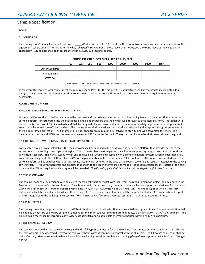
SOUND 7.1 SOUND LEVEL The cooling tower's sound levels shall not exceed dB at a distance of 5 (50) feet from the cooling tower in any cardinal direction or above the equipment. Where sound criteria is determined by job specific requirements, those levels shall not exceed the sound levels as indicated on the chart below. Sound data shall be in accordance with CTI ATC-128 test procedures.
SOUND PRESSURE LEVEL MEASURED AT 5 (50) FEET
63 125 250 500 1000 2000 4000 8000 dB(A)
AIR INLET SIDES
CASED SIDES
VERTICAL
Lp SOUND PRESSURE LEVELS ARE EXPRESSED IN (Db) REFERENCE 0.0002 MICROBAR
In the event the cooling tower cannot meet the required sound levels for the project, the manufacturer shall be required to incorporate a fan design that can meet the requirement or utilize sound attenuation as necessary. Units which do not meet the sound requirements are not acceptable. ACCESSORIES & OPTIONS 8.0 ACCESS LADDER & PERIMETER HAND RAIL SYSTEMS Ladders shall be installed to facilitate access to the mechanical drive system and access door of the cooling tower. In the event that an external service platform is incorporated into the overall design, the ladder shall be designed with a walk through to the access platform. The ladder shall be constructed to current OSHA standards and shall be designed of non-corrosive aluminum material with safety cage constructed of galvanized steel that adheres strictly to OSHA standards. The cooling tower shall be designed with a galvanized tube handrail system along the perimeter of the fan deck for fall protection. The handrail shall be designed from a minimum 1 ¼” galvanized steel tubing with galvanized fasteners. The handrail shall comply with OSHA requirements and we extend 42” from the fan deck. The system will include handrail, knee rail, and toe guard. 8.1 EXTERNAL COLD WATER BASIN SERVICE PLATFORM & LADDER For elevated cooling tower installations the cooling tower shall be supplied with a cold water basin service platform that provides access to the access door of the cooling tower’s plenum region. The cold water basin service platform shall be self-supporting design constructed of hot dipped galvanized steel (HDG) (Stainless Steel 304) with anti-skid walking surface and supplied with a complete handrail system which includes hand rail, knee rail, and toe guard. The platform shall be OSHA compliant and capable of a maximum 60 PSF live load or 300 pound concentrated load. The service platform will be supplied with a vertical access ladder which extends to the base of the cooling tower and is securely fastened to the cooling tower structure. Mounting hardware and brackets that attach to the cooling tower shall be made of identical materials of construction at the point of connection. When required a safety cages will be provided. (A self-closing gate shall be provided at the step through ladder location.) 8.2 VIBRATION SWITCH The cooling tower shall be designed with an electro-mechanical vibration switch with local reset, designed to monitor, detect, and de-energize the fan motor in the event of excessive vibration. The vibration switch shall be factory mounted to the mechanical support and designed for operation within the cooling tower plenum and housed within a NEMA 4/4X IP66 (CSA types 4 and 12) enclosure. The unit is supplied with a local reset button and adjustable sensitivity dial which offers a range of 0-7G. The mechanical switch shall be designed with dual SPDT capability and capable of being integrated to the building’s BMS system. (The switch shall be furnished a remote reset option in either 115 VAC or 24 VDC). 8.3 BASIN HEATERS The cooling tower shall be provided with kW basin heater(s) for cold climates that are prone to freezing conditions. The heater selection shall be made by the factory and will be designed to maintain a minimum cold water temperature of no less than 40oF at 0oF (-20oF/-40oF) ambient . The electric basin heater shall incorporate a low water cutout switch and an adjustable thermostat housed within a NEMA 4x enclosure. 8.4 FILL BYPASS CONNECTION The cooling tower cold water basin will be supplied with a fill bypass connection for use in cold weather climates or when conditions are such that the inlet water is to be diverted directly to the cold water basin without coming into contact with the fill media. The fill bypass connection shall be a side (bottom) oriented connection that is beveled for weld and grooved for mechanical coupling (flanged to accept an ASME B16.5 Class 150 type flange).
AMERICAN COOLING TOWER INC. ACX SERIESSample Specification
20www.AmericanCoolingTower.com
8.5 MECHANICAL DAVIT The cooling tower shall be supplied with a removable and portable light-weight aluminum davit that is designed to assist removal of the fan motor or fan assembly when servicing or maintenance is required. The davit shall be designed with a factory mounted fixed base, one per cell, constructed of identical materials as that of the upper section of the cooling tower and designed for a maximum weight load of 200% of the motor weight. 8.6 INTERNAL SWEEPER PIPING The cooling tower shall include an integrated internal sweeper piping system for connection to an external water filtration system. The internal sweeper piping shall be designed with separate supply and return lines which are constructed of schedule 40 PVC piping no less than 2” in diameter. The return piping shall be located in the depressed region of the cold water basin and shall incorporate a series of collection holes which are no less than 1/2” in diameter. The collection holes shall be located facing downwards, slightly elevated off the basin floor to allow debris to be pulled into the circulating water and directed back to the filter system. Points of connection shall be by PVC bulkhead fittings for galvanized cold water basins. Stainless steel cold water basins shall utilize stainless steel welded couplings which are of identical material to the basin.
8.6a EDUCTOR NOZZLES
The supply piping shall incorporate ABS sweeper jets designed to create a negative pressure region at the nozzle outlet to induce ambient basin water into the elliptical discharge of the nozzle and direct the water discharge to a return pipe located in the depressed area of the cold water basin. The nozzles shall be spaced evenly from the point of connection to the end of the supply pipe. Nozzles shall be swivel mounted so that they can be adjusted as needed. Nozzles which are fixed body type shall not be accepted.
8.7 ELECTRONIC WATER LEVEL CONTROL HIGH/LOW ALARM The cooling tower shall include an electric water level control device which is designed to operate by monitoring water levels within the cold water basin by way of stainless steel probes housed within an externally mounted stilling chamber. The probes shall be designed to monitor high and low water levels which will open and close the brass solenoid valve to regulate water levels within the cold water basin. The five probe system includes additional probes which are designed as high and low water level alarms for additional monitoring and protection. The control panel utilizes dry contact locations for remote monitoring and is provided with a 110 dB alarm at the control panel in the event that the low or high alarm is triggered. The electric water level controls shall be housed within a NEMA 4x enclosure designed for outdoor operation. 8.8 QUICK FILL LINE The cooling tower shall be provided with an external point of connection which can permit full flow filling capability of the cooling tower basin in addition to the make-up connection. The quick fill line shall be located adjacent to the make-up connection for ease of tie-in to make-up water line and is designed to help accelerate the filling of the cooling tower following shutdowns that require the system to be drained. The connection type shall be NPT and diameter shall match the make-up connection size of the specified model. 8.9 VARIABLE FREQUENCY DRIVE The cooling tower shall be furnished with a high quality, easy to use, variable frequency drive designed to monitor cold water basin temperatures and efficiently monitor fan power operation to minimize energy costs based on designated set points. The drive selection will be based on the electrical service and cooling tower horsepower as indicated on the mechanical schedule. The VFD Drive conforms to NEMA ICS 3.1 and shall be capable of operating without fault or failure when the voltage varies plus 10% or minus 15% from rating, and frequency variations of plus or minus 5%. The variable frequency drive shall be furnished in a NEMA 1 (NEMA 3R) (NEMA 12) enclosure and shall include a two contactor manual bypass when required. The VFD and bypass package shall be NEMA rated, fully pre-wired and read for installation as a single UL listed device. The VFD drive shall be furnished with a 2 year warranty and startup shall be conducted by an authorized local startup company. 8.10 SINGLE POINT CONTROL PANEL The cooling tower shall be furnished with a single point electrical supply control panel for the cooling tower cell(s) with features and functions in accordance to the plans and specifications. The minimum requirements of the control panel shall be to provide a single point of electrical power supply capable of operating the cooling tower fan motors and electrical accessories or components being supplied. The single point electrical panel shall provide branch circuit protection to each motor, controls transformer, and electric basin heaters when present. Panel shall provide visual indicator lights and alarm for signal an event associated with temperature, vibration, or power loss. Unit shall be supplied within a fused enclosure with lockable door and an HOA switch for motors. The enclosure shall be NEMA 1 (NEMA 3R) (NEMA 12) (NEMA 4X) type and provide scalable contact points for the accessories and options and permit signal wiring to be integrated to the panel for BMS monitoring. When a VFD is used in conjunction with the single point electrical panel, the VFD from section 9.10 shall be housed within the enclosure which is sized according to requirements. All panels shall be UL listed.
AMERICAN COOLING TOWER INC. ACX SERIESThermal Guarantee
21 www.AmericanCoolingTower.com
The ACX Series cooling tower models listed at http://www.cti.org/certification.shtml have had their published capacities certified under CTI Standard 201 Test Code and are listed under validation number C38C-18R00
The ACX series packaged cooling tower design manufactured by AMERICAN COOLING TOWER INC., is provided with a THERMAL GUARANTEE stating that based on design conditions presented in bid documents or requirements provided by the client, tower performance shall meet or exceed a minimum of 95% capacity as is acceptable under CTI Standards & Testing and verified by a Thermal Acceptance Test performed under CTI ATC-105 testing standards
certifying that the unit’s thermal performance has been tested and meets CTI standards for thermal capacity ratings.
Upon the owner’s request an ATC-105 thermal acceptance test can be provided at the owner’s expense if they suspect that the cooling tower is not meeting thermal performance as required by the technical specifications supplied. A thermal acceptance test shall be provided by a third party testing
agency to conduct the ATC-105 thermal acceptance per CTI requirements. Upon completion of the thermal test a report shall be provided to the customer confirming the results. This report will be furnished to both American Cooling Tower and the owner and is considered a legal document and will be
recognized as such by all parties involved.
In the event that the suspected unit(s) do not pass the CTI ATC-105 thermal acceptance test, American Cooling Tower, will be held responsible for making any and all changes to the existing cooling tower(s) or replacing the existing cooling tower(s) to bring the unit into an acceptable performance range as
defined by ATC-105 testing standards. In addition American Cooling Tower will be responsible for additional testing. If the unit(s) pass the ATC-105 test, the owner is responsible for all costs and fees associated with the conducting the test procedure.
Thermal Guarantees will be void should any design conditions be altered without the acknowledgement of American Cooling Tower. Any obstructions that limit air flow or cause air recirculation may also void thermal guarantees. American Cooling Tower provides a thermal guarantee under the assumption that
the customer will maintain preventative maintenance as instructed by AMERICAN COOLING TOWER and uses only Factory Authorized Parts supplied by American Cooling Tower. Any parts, accessories, or optional components not supplied by American Cooling Tower, which may affect cooling performance
will void thermal guarantee. The owner should consult with the factory prior to the installation of any components, platforms, ladders, or other accessories that may affect cooling tower performance.
ACX SERIES SINGLE & MULTIPLE CELL MODELS; STD-201 VALIDATION NUMBER C38C-18R00SOME OPTIONS AND ACCESSORIES MAY VOID 201 CERTIFICATION
AMERICAN COOLING TOWER ACX SERIES COOLING TOWER THERMAL GUARANTEE
AMERICAN COOLING TOWER INC. ACX SERIESWarranty
22www.AmericanCoolingTower.com
ACT OFFERS FLEXIBLE WARRANTY PLANS WHICH INCLUDE:
For more information please contact your representative or you can call 1-800-371-5959.
AMERICAN COOLING TOWER warrants the mechanical equipment of their ACX series packaged system which includes the bearings, fan(s), fan motor(s), pulley(s), shaft(s), and mechanical support(s) for a period of one (1) year from the date of shipment by AMERICAN COOLING TOWER. Warranty coverage ensures that the mechanical components of the ACX series cooling tower will be free of defects in materials and workmanship. Any component not mentioned previously will be guaranteed to be free of defects associated with materials or workmanship for a period of one (1) year from the date of installation or for a period of eighteen (18) months from the date of shipping, whichever time expires first, by AMERICAN COOLING TOWER. The components that are included in the one (1) year or eighteen (18) month coverage period include; fill media, structural components, drift eliminators, inlet louvers, fan belts, make-up valve(s), vibration switches, or any other component not included in the standard one (1) year mechanical warranty.
In addition to the equipment warranty, AMERICAN COOLING TOWER offers a performance guarantee which states that the cooling tower specified in the CERTIFIED UNIT DRAWING will meet the designed specifications as indicated for the project for a period of one (1) year from date of installation or eighteen (18) months from the date of shipping by AMERICAN COOLING TOWER, whichever time expires first. If after installation and startup, the tower is not operating as specified, at the customer’s request, AMERICAN COOLING TOWER technicians will perform a thorough inspection and performance test of the installed unit. The customer, consulting engineer, and manufacturer representative will be permitted access to observe the performance test and inspection. If the results of the performance test or the inspection show the equipment to be deficient, AMERICAN COOLING TOWER will make any necessary repairs or alterations to correct the problem at no additional cost to the owner. If following the inspection the unit is found to be in accordance with the certified drawings and stated performance, the owner will reimburse AMERICAN COOLING TOWER for all direct expenses associated with the performance test and inspection.
No other warranties written or verbal will supersede the above warranty statement. The sole remedy for breach of the warranty as stated above will be the repair or replacement of the equipment by AMERICAN COOLING TOWER at its option. Any third party labor or components that are installed onto the unit after unit is shipped by AMERICAN COOLING TOWER will void any warranty unless the components or accessories are approved in writing by AMERICAN COOLING TOWER. In addition, warranty coverage will be void if the owner does not perform preventative maintenance as recommended and operate the cooling tower in accordance to AMERICAN COOLING TOWERS’ operation and maintenance manual. AMERICAN COOLING TOWER standard warranty as stated above is void in the event of natural disasters, riots, wars, or acts of God which result in the loss of the cooling tower. Under no circumstances will AMERICAN COOLING TOWER be liable for lost profits, lost savings, personal injuries, incidental damages, economic loss, property damage, or any other consequential, incidental, special or contingent damages. In addition, AMERICAN COOLING TOWER shall not be responsible for any injuries or damages of any kind whatsoever under any theory of tort to the extent caused by misuse of the product by the buyer or any third party. Warranty EXCLUDES labor to perform the repairs and shall be at the OWNER’S expense unless otherwise agreed upon in writing by AMERICAN COOLING TOWER.
Owner agrees to all terms outlined above in the stated warranty and this agreement is acknowledged upon owner’s issuance of a purchase order and AMERICAN COOLING TOWER agrees to the above warranty at the time of purchase order acceptance.
AMERICAN COOLING TOWER STANDARD ACX SERIES COOLING TOWER WARRANTY STATEMENT
One Year Mechanical Warranty - One Year Total Product
5 Year mechanical / 1 Year total product (Parts Only)
5 Year mechanical / 1 Year total product (Parts & Labor)
5 Year Total Product (Parts Only)
5 Year Total Product (Parts & Labor)
Extended warranties beyond 5 years are also available

ACX Series Cross Flow Induced Draft Cooling Towers
.
Engineering Data
CORPORATE OFFICE:American Cooling Tower, Inc.6411 Maple AvenueWestminster , CA 92683800-371-5959www.americancoolingtower.com Member
YOUR REPRESENTATIVE IS:
Publication #ACX-132
Low Noise ‘SC’ fans with VT Technology fans come standard on all units and provide superior sound levels when compared to most competitor’s standard fan designs.
Xtreme Low Noise ‘XC’ Fans offer superior construction and sound levels without the use of expensive FRP sweeping blade fans which are prone to cracking and failure over time and are provided at a fraction of the cost.
Low Noise Options
American Cooling Tower provides the ACX Series cooling tower with several fan design options to help meet the growing need to provide units which operate at reduced sound levels. In the past and even today, many manufacturers have capitalized on sound requirements by charging top dollar for these options.
At American Cooling Tower, we do not believe that sound should come at a premium to our clients.
All of our fans are constructed from light-weight, high grade 5052 marine aluminum which offers maximum resistance to corrosion and reduced weights for longer mechanical life. In addition, all of the fan designs offered on our ACX series units incorporate a resilient mount system which allows the fan blades to automatically adjust based on speed variations associated with inverter duty operation. This feature reduces the need to lockout VFD ranges and permit clients with the ability to operate their towers across a wider range to maximize energy efficiency.
Whether you are looking at our Low Noise ‘SC’ Fans, Super Low Noise ‘EC’ Fans, or have a need for our Xtreme Low Noise ‘XC’ fan design, rest assured that American Cooling Tower will help you choose the right fan for your application.
*Some options and accessories are excluded from CTI STD-201 certification. This is subject to change without notice.