Embed Size (px)
Citation preview
NASA/TP--2000-210047
ACTS Ka-Band Earth Stations: Technology,Performance, and Lessons Learned
Richard C. Reinhart
Glenn Research Center, Cleveland, Ohio
Steven J. Struharik
COMSAT Laboratories, Clarksburg, Maryland
John J. Diamond
Analex Corporation, Brook Park, Ohio
David Stewart
GTE Technology Organization, Cleveland, Ohio
May 2000
https://ntrs.nasa.gov/search.jsp?R=20000076604 2018-09-07T08:27:58+00:00Z
The NASA STI Program Office... in Profile
Since its founding, NASA has been dedicated to
the advancement of aeronautics and spacescience. The NASA Scientific and Technical
Information (STI) Program Office plays a key part
in helping NASA maintain this important role.
The NASA STI Program Office is operated by
Langley Research Center, the Lead Center forNASA's scientific and technical information. The
NASA STI Program Office provides access to theNASA STI Database, the largest collection of
aeronautical and space science STI in the world.
The Program Office is also NASA's institutionalmechanism for disseminating the results of its
research and development activities. These resultsare published by NASA in the NASA STI Report
Series, which includes the following report types:
TECHNICAL PUBLICATION. Reports of
completed research or a major significantphase of research that present the results of
NASA programs and include extensive dataor theoretical analysis. Includes compilations
of significant scientific and technical data and
information deemed to be of continuingreference value. NASA's counterpart of peer-
reviewed formal professional papers buthas less stringent limitations on manuscript
length and extent of graphic presentations.
TECHNICAL MEMORANDUM. Scientific
and technical findings that are preliminary orof specialized interest, e.g., quick release
reports, working papers, and bibliographiesthat contain minimal annotation. Does not
contain extensive analysis.
CONTRACTOR REPORT. Scientific and
technical findings by NASA-sponsoredcontractors and grantees.
CONFERENCE PUBLICATION. Collected
papers from scientific and technical
conferences, symposia, seminars, or other
meetings sponsored or cosponsored byNASA.
SPECIAL PUBLICATION. Scientific,
technical, or historical information from
NASA programs, projects, and missions,often concerned with subjects having
substantial public interest.
TECHNICAL TRANSLATION. English-
language translations of foreign scientific
and technical material pertinent to NASA'smission.
Specialized services that complement the STI
Program Office's diverse offerings include
creating custom thesauri, building customizeddata bases, organizing and publishing researchresults.., even providing videos.
For more information about the NASA STI
Program Office, see the following:
• Access the NASA STI Program Home Pageat http://www.sti.nasa.gov
• E-mail your question via the Internet to
• Fax your question to the NASAAccess
Help Desk at (301) 621-0134
• Telephone the NASAAccess Help Desk at(301) 621-0390
Write to:
NASA Access Help Desk
NASA Center for AeroSpace Information7121 Standard Drive
Hanover, MD 21076
NASA/TP--2000-210047
ACTS Ka-Band Earth Stations: Technology,Performance, and Lessons Learned
Richard C. Reinhart
Glenn Research Center, Cleveland, Ohio
Steven J. Struharik
COMSAT Laboratories, Clarksburg, Maryland
John J. Diamond
Analex Corporation, Brook Park, Ohio
David Stewart
GTE Technology Organization, Cleveland, Ohio
Prepared for the
Sixth Ka-Band Utilization Conference
sponsored by the Istituto Internazionale delle Comunicazion
Cleveland, Ohio, May 31--June 2, 2000
National Aeronautics and
Space Administration
Glenn Research Center
May 2000
Acknowledgments
The authors wish to thank the many people and organizations who have contributed to the work described herein.
Throughout the ground-station development and operations, many technical and nontechnical contributionswere made. We would like to acknowledge the feedback from the experimenter community to improve
station operations, the industry partners who advanced Ka-band technologies, and the earth station
teams and all support personnel who implemented the experiments program.
NASA Center for Aerospace Information7121 Standard Drive
Hanover, MD 21076
Price Code: A03
Available from
National Technical Information Service
5285 Port Royal Road
Springfield, VA 22100Price Code: A03
ACTS Ka-Band Earth Stations:
Technology, Performance, and Lessons Learned
Richard C. Reinhart
National Aeronautics and Space AdministrationGlenn Research Center
Cleveland, Ohio 44135
Steven J. Struharik
COMSAT Laboratories,
Clarksburg, Maryland 20871
John J. Diamond
Analex Corporation
Brook Park, Ohio 44142
David Stewart
GTE Technology Organization
National Aeronautics and Space AdministrationGlenn Research Center
Cleveland, Ohio 44 135
Summary
The Advanced Communications Technology Satellite
(ACTS) Project invested heavily in prototype Ka-band satellite
ground terminals to conduct an experiments program withACTS. The A(_TS experiments program proposed to validate
Ka-band satellite and ground-station technology, demonstratefuture telecommunication services, demonstrate commercial
viability and market acceptability of these new services, evalu-
ate system networking and processing technology, and charac-
terize Ka-band propagation effects, including development of
techniques to mitigate signal fading.
This paper will present a summary of the fixed ground
terminals developed by the NASA Glenn Research Center and
its industry partners, emphasizing the technology and perfor-mance of the terminals and the lessons learned throughout their
6-year operation, including the inclined orbit phase-of-
operations. An overview of the Ka-band technology and com-
ponents developed for the ACTS ground stations is presented.
Next, the performance of the ground-station technology and its
evolution during the ACTS campaign are discussed to illustrate
the technical tradeoffs made during the program and highlight
technical advances by industry to support the ACTS experi-
ments program and terminal operations. Finally, lessons learned
during the development and operation of the user terminals are
discussed for consideration of commercial adoption into future
Ka-band systems.
The fixed ground stations used for experiments by government,academic, and commercial entities used reflector-based offset-
fed antenna systems with antennas ranging in size from 0.35 to
3.4 m in diameter. Gateway earth stations included two systemsreferred to as the NASA Ground Station (NGS) and the Link
Evaluation Terminal (LET). The NGS provides tracking, telem-
etry, and control (TT&C) and Time Division Multiple Access(TDMA) network control functions. The LET supports technol-
ogy verification and high-data-rate (HDR) experiments.
The ground stations successfully demonstrated many ser-
vices and applications at Ka band in three different modes-of-
operation: circuit-switched TDMA using the satellite onboard
processor, satellite-switched TDMA (SS-TDMA) applications
using the onboard Microwave Switch Matrix (MSM), andconventional transponder (bent-pipe) operation. Data rates
ranged from 4.8 kbps up to 622 Mbps. Experiments included (a)
a low rate (4.8 to 100 kbps) remote data acquisition and control
using small earth stations, (b) moderate rate (l to 45 Mbps)
experiments with full duplex voice and video conferencing and
both full duplex and asymmetric data rate protocol and network
evaluation using midsize ground stations, and {c) link charac-
terization experiments and HDR ( 155 to 622 Mbps) terrestrial
and satellite interoperability application experiments conducted
by a consortium of experimenters using the large transportable
ground stations.
Overview of Ground Stations
The ground stations developed by NASA Glenn ResearchCenter (GRC) and its industry partners included five different
NASA/TP-2000-210047 1
sizeterminals,eachwithuniquecapabilitiesdesignedtomeetasetofapplicationsforexperimentsanddemonstrationatKaband.Thelargeground-stationfacilitiesof theACTS/GRCprogramaretheNASAGroundStation(NGS)andtheLinkEvaluationTerminal(LET).TheNGSservesas(a)ACTSprimarytrackingtelemetryandcontrol(TT&C)station,(b)aBasebandProcessor(BBPI/VerySmallApertureTerminal(VSAT)TimeDivisionMultipleAccess(TDMA)networkreferencestation,(c)twoVSATtrafficterminals,and(d)abackupfacilityto theLETfor MicrowaveSwitchMatrix(MSM)experimentoperations.TheLETservesas(a)ahubfortheUltraSmallApertureTerminal(USAT)starnetworkex-periments,(b)ahigh-data-rate(HDR)terminalintheGigabitNetwork,(c)anexperimenterstationusedtoconducttechnol-ogyverificationexperimentssuchaswidebanddispersionandantennawetting,(d)anon-orbittestbedforACTSspacecraftcharacterizationmeasurementsincludingfrequencyresponseandmultibeamantennacharacterization,and(e)a backupfacilityfortheTT&CfunctionofACTS.
ThefamilyofexperimenterortransportablegroundstationsincludesVSAT,USAT,andtheHDRterminal.Eachterminalwasoriginallydesignedto supportcertainapplications.Asadvancesin technologyoccurredoverthecourseofthepro-gram,eachterminaldemonstratedmoreadvancedapplications,furtherdemonstratingthecapabilitiesofgroundstationsatKaband.TheVSATandACTSTDMAnetworkwereinitiallyusedfor1.544-Mbpsvideoconferencingandteleconferencingbasedon64-kbpschannelsandfadecompensationalgorithmevaluation.Overthecourseof the program the terminals were
deployed for protocol and network experiments, propagation
data collection and analysis, TDMA network availability ex-
periments, and technology experiments to evaluate the satellite
multibeam antenna performance. The USAT ground stations
were originally designed to demonstrate supervisory control
and data acquisition for remote electric utility stations and usedkbps data rates• Advances, primarily in solid-state amplifier
technology, enabled the stations to demonstrate > 1.544-Mbps
videoconferencing, highly asymmetric (1.544/45 Mbps) product
NAME MODE ANTENNA
(m)
NGS BBP
VSAT BBP
USAT MSM
HDR MSM
LET MSM
I-IPA
(Watt)
5.5 200
1.2, 2.4 12
0.6, t.2 .25, 1.0, 2.0
3.4 120
4.7 100
EIRP G/T
((mW) (dB/K)
78 30
60, 66 16-18
35-51 15, 21
76 28
78 27
and content distribution applications, and 2-Mbps full meshTDMA/FDMA Internet Protocol (IP) and asynchronous trans-
fer mode (ATM) network experiments. The HDR station was
first deployed to demonstrate interconnectivity of
supercomputers to conduct interactive computer modeling at
high data rates. Over the duration of the program the stations
were redeployed to demonstrate high-rate commercial IP aug-
mentation, optimized file transfer protocol (FTP), and technol-
ogy verification experiments and characterizations.
ACTS has two modes-of-operation: MSM and BBP. The
MSM mode-of-operation functions as a bent-pipe memoryless
repeater with frequency translation. A microwave switch at the
satellite Intermediate Frequency (IF) connects uplink antennas
to appropriate downlink antennas for static point-to-point con-
nections. The MSM may also be programmed using a repeating
uplink/downlink connection sequence for an SS-TDMA net-
work for HDR operations. The BBP provides onboard storage
and routing of baseband signals for the VSAT TDMA network.
Signals from each transmitting VSAT are demodulated by the
BBP aboard the satellite and routed to the appropriate receiving
station by illuminating the appropriate spot beams over the
respective transmitting and receiving stations. 1 The satellite
burst time plan dynamically updates based on orderwire re-
quests from stations entering the network or if existing stations• . . "_
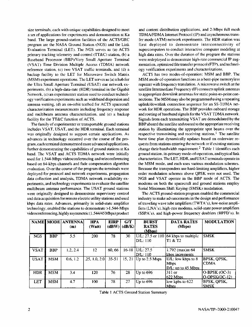
change their bandwidth reqmrement.- Table 1 identifies each
ground station, its primary mode-of-operation, and typical link
characteristics. The LET, HDR, and USAT terminals operate inthe MSM mode, and each uses various modulation schemes.
Because the transponders use hard-limiting amplifiers, higherorder modulation schemes above QPSK were not used. The
NGS and VSAT operate in the BBP mode of ACTS. The
modems on both the spacecraft and ground stations employ
Serial Minimum Shift Keying (SMSK) modulation.
The ACTS ground-station program enabled the commercial
industry to make advancements in the design and performance
of traveling wave tube amplifiers (TWTA's), low-noise ampli-
tiers (LNA's), high-rate modems, solid-state power amplifiers
(SSPA'sL and high-power frequency doublers (HPFD's). In
BURSTRATES
U/L: 27.5 or 110D/L: 110
U/L: 27.5D/L: 110
Up to 2.5 Msps
Up to 696
Up to 696
DATA RATES
(Mbps)
64 kbps to multipleT1 &T2
1.792 (max)at 64kbns increments
U/L: low kbps to 8MbpsD/L: up tO 45 Mbos311 or
622 Mbps
low kpbs to 622Mbps
Table 1 ACTS Ground Station Summary
MODULATION
SMSK
SMSK
BPSK, QPSK,CDMA
O-BPSK (OC-3)0-QPSK(OC-12)BPSK, QPSK,SMSK
2 NASA/TP-2000-210047
addition,althoughoutsidethescopeofthispaper,thedevelop-mentoftheonboardprocessingTDMA network enabled vari-
ous satellite and ground-station technologies not addressed
here. The implementation of commercial terrestrial interfaces
laid a foundation for terrestrial and satellite interoperability
experiments, commercial protocol research and augmentation,and other technical advancements. The radiofrequency (RF)
technologies developed for the ACTS ground terminals, with a
few exceptions, were mainly extensions of technologies devel-
oped at lower frequency bands. Still, the design challenges
were quite real and required significant engineering effort to
overcome. The final result was high-quality ground-station
equipment that continued to perform well beyond the intended
operational life of the system.
Ground-Station Technologies
Transmitter
Development and operation of the 30-GHz Ka-band travel-
ing wave tube amplifiers proved challenging in the early years
of ACTS. The NGS and LET were the first to procure 30-GHz
TWTA's. The NGS and LET began ground-station integration
and testing in the late 1980' s and early 1990's. Four 54-W units
were initially purchased for use in the NGS, followed by three60-W units for use in the LET, all from the same vendor. The
TWT designs used in the LET and NGS units were similar. The
TWT's were linear beam devices with a helix type slow-wavemicrowave circuit.
These first "I"WTA' s experienced several problems. The first
anomaly, a spontaneous shutdown of the TWTA protection
circuitry, was reported in 1992. 3 Testing revealed random
output power spikes ( 1- to 3-dB RF power fluctuations) present
at certain frequencies. Naturally, the random power spikescontributed to loss of data bits and resultant increase in bit error
rate (BER). The effect would appear in the 10 -8 BER range.
Strong spikes resulted in the spontaneous shutdown of the
TWTA. Test data and analysis provided to the vendor contrib-
uted to modifications in TWTA design to minimize the effect
of the power spikes. Although TWTA's in general experience
RF fluctuations, the low BER experiments conducted in the
ACTS program were more susceptible to these types of compo-
nent characteristics. Other problems that occurred were highhelix current shutoff and an inability to power a unit on. Over
time the latter problem was attributed to the operational proce-dure of the TWTA.
The operations procedure at the start of the program was to
allow the TWTA to run without RF drive during short periods
of inactivity and turn off the TWTA during longer periods ofinactivity (e.g., overnight). Regularly turning the unit off and
on or leaving the unit turned off for short periods of time tended
to create gas in the vacuum envelope of the tube. This resulted
in a high helix current causing the helix protection circuitry to
power the unit off or prevent the unit from turning on. It is also
believed that this operational practice led to shortened TWTA
life. These practices and the technical problems mentioned
resulted in regular occurrences of TWTA malfunctions and
lengthy repair cycles. The TWTA's were routinely sent to the
vendor to repair high-voltage components or to degas the unit.
Due to the sporadic shutoffs and operational difficulties, the
original TWTA's were never run to end-of-life and were
replaced by a next-generation TWT from the same vendor (forLET) and new TWTA's from other vendors for both NGS and
LET. The original TWTA's had 7000 to 10 000 hr beforeremoval from service.
The TWTA operations procedure for both LET and NGS was
changed such that energized tubes were never permitted to idle
for long periods of time without high voltage applied. Also,
they were always operated with an applied carrier, eitherradiated or transmitted into a load. Particular attention was also
paid to maintaining proper cooling. This resulted in a very
stable operating environment, significantly extending TWTAservice life.
The combination of change in operational procedures and
improvements made in the second-generation TWTA's used inthe LET increased TWTA service life. A new TWTA (from the
original vendor) was removed from service with over 20 000 hr
of operation. The helix current remained stable and only
increased near end-of-life, as expected. The LET TWTA from
the second vendor provided 100-W output power using a
120-W tube. Internal components, primarily the output isola-
tor. TWTA also employed a helix-type structure tube and
power supply in a single housing. The second vendor" s TWTA
has been in service at LET for over 22 000 hr as of this writing.
Replacement TWTA's for both the NGS and LET were
procured from new and different vendors than the original
TWTA's. The NGS tubes are capable of 200-W output power,
but internal component losses and biasing result in a saturated
power level of 150 W at the amplifier output. The slow-wave
structure of the tube is a coupled cavity, that is, the tube does not
have an actual helix but rather an interdigital delay line that
performs the same function as a helix. The circuit was devel-
oped as a better way of realizing the slow-wave structure, given
the high power level and the stringent size and accuracy
requirements in the millimeter wave range. This design is not
as broadband as tubes using actual helices. The NGS TWTA's
use a split mount design with separate units for the TWT and
power supply.The design life of the second-generation NGS TWT collec-
tors and electron guns are 20 000 to 30 000 hr. However,
original tubes delivered with the new TWTA's lasted only
10 000 to 12 000 hr with one premature failure at 2700 hr. The
failures occurred for various reasons including materials used
in the tube, mechanical shock, and the precision tolerances
required in the tube structure at Ka band. Another factor was the
stability of the delay line inside the tube. The attenuation of
each section must be stable over the operating temperature
NASA/TP-2000-210047 3
rangetoavoidproblemswithgainripple.AsexperiencewasgainedwithtubeoperationintheNGSandwithotherusers,thevendorexaminedtubefailuresandmadeimprovementsinthetubedesignandmaterialsused.Thedesignchangesresultedinsimilartubedesignlifeandachievedamuchlongeroperatinglife--closerto30000hr.
TheVSATtransmitterusedKu-bandTWT'soperatingat14.6GHzcombinedwithanHPFD.TheTWT,powersupply,andfaultcircuitswereenclosedin theIntermediatePowerAmplifier(IPAenclosure).Theunitproduced45-dBmoutputwitha -5-dBminputsignal.TheIPAdrivestheHPFDtoproducethefinaloutputfrequencyof29.2GHzat40.5dBm.TheIPAdutycyclewas25percentundernormaloperatingconditionsinTDMAburstmode.ACpowerisappliedtotheunitatalltimesandmonitoredonanhourmeter.TheaveragelifeofeachIPAisabout26000hror3years.TheIPApowersuppliesweretypicallythefirsttofail.RepairingthepowersupplyunitswouldextendtheTWTlifetoabout30000hr.
WiththedecisiontoextendtheACTSprograminlate1995,aftertheinitialexperimentphase(2years),mostVSATTWT'sandHPFD'swereintheirthirdyear.DuetotheIPAreachingend-of-lifeanddesignissueswiththeHPFD,atradeoffwasevaluated:whethertostaywiththeIPAandHPFDdesignorusenew30-GHzSSPA'scapableof therequired10-to 12-Woutputpower.TheSSPA'swereavailablefroma limitedsupplyof vendors.However,theoutputpowerspecificationwasdifficulttomeetandsomemanufacturerscouldnotguar-anteeareliableproduct.Becausethechangeintechnologieswouldincursubstantialcostandincreaserisk,theprojectstayedwiththeIPA/HPFDdesignandreplacedtheIPAentirelyandredesignedtheHPFD's.
ThefirstHPFD'susedin operationwerenotdesignedtooperatewithacontinuouswave(CW)signalapplied.Priortolaunch,theprojectidentifiedtheneedtocharacterizeandtesttheHPFD'swithaCWsignalduringoperations.A secondproblemwiththeoriginalHPFD'swasthattheyoperatedathightemperatures,andseveralunitsfailedafteronlyafewmonthsduetodiodefailures.EachHPFDhadfourdiodesthatproducedtheoutputpowerandfrequencydoubling.Thenewunitsproducedweredesignedfor CW, operated at lower
temperature, and used a different diode biasing design. Otherdesign changes included a new balanced diode assembly andadditional heat sinks applied to each individual diode. Reduced
VSWR made the diode less susceptible to standing waves and
voltage spikes. The entire fleet of VSAT's (19) was upgradedwith new HPFD's as the original units continued to fail.
Although the new HPFD design was more reliable than the
original, the units were still the source of many VSAT failures.Experience and testing with the VSAT's determined that the
IPA produced voltage spikes that degraded the HPFD's over
time. The IPA/HPFD redesign significantly improved the sys-
tem availability of the VSAT network. Although the technol-
ogy used required regular terminal maintenance, the reliability
data of both the IPA and HPFD enabled system engineers to
plan repairs and service each station before unexpected failures
occurred and reduced troubleshooting time to minimize impactto the experiments program.
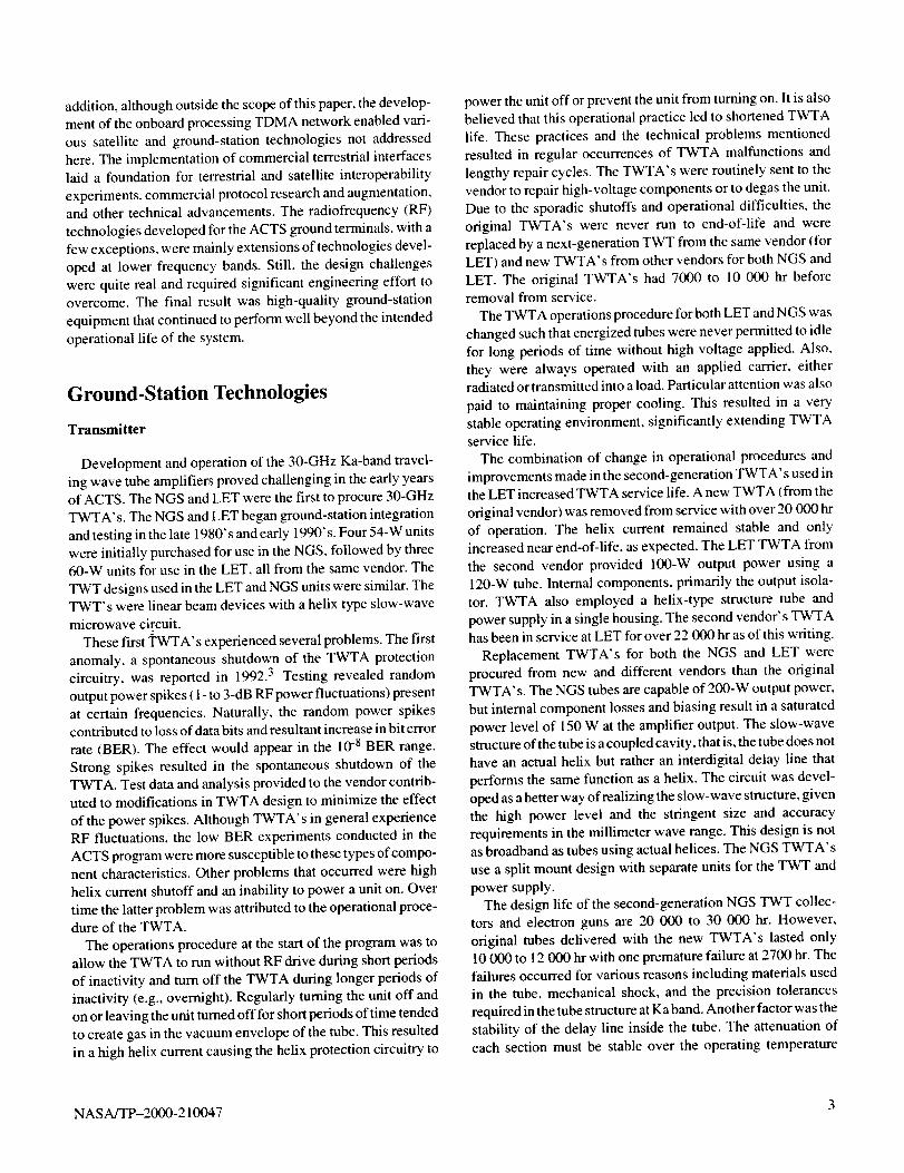
The USAT transmitters employed low-power SSPA' s. In the
early 1990's, cost and availability limited these discrete com-
ponent amplifiers to 0.25 W. Combined with a single-stage
upconverter from 800 MHz to 30 GHz, the resultant package
was a small 5- by 3- by l-in. upconverter/amplifier integratednear the feed of the antenna to minimize loss. As solid-state
technology matured, a second version of the block upconverterwas produced in 1997. The second generation used 1-W Mono-
lithic Microwave Integrated Circuit (MMIC) amplifiers with a
two-stage upconverter (70 MHz to 30 GHz), yet only a small
increase in size resulted. The new units measured 5 by 4 by 1 in.
as shown in figure I. In addition, 2-W units were also produced
in the same size package by combining two 1-W MMIC chips.
Two challenges of these higher power units were achieving
good component yield and hand selecting the highest power
chips for integration. This resulted in good overall performance
and stable operation over temperature with losses of only 1 to
1.5 dB at 80 °C. Solid-state amplifiers in the 4- to 10-W range
were also available in the late 1990's, but cost and integrationprohibited their use. The goal of the USAT was a modest data
rate (>1.544 Mbps) with small packaging, which was achievedwith the 1- and 2-W units. As successful as these units were in
size, operation, and performance, advances are still needed in
device yield and unit production and integration to make theseproducts affordable for the mass market.
The HDR station also employed 30-GHz high-power
TWTA's. The units were a split-mount design with a 12-m
cable to remotely control and supply power to the TWT. TheTWTA was mounted on the boom of the antenna near the feed
with the power supply and preamplifier rack mounted inside the
HDR equipment trailer. Like the LET TWT, the HDR TWT
was designed around a helix-type slow-wave microwave circuit
with an output of 100 to 120 W and >I-GHz bandwidth. Unlike
other terminals, the HDR TWTA remained powered down for
Figure I USAT 1-Watt upconverter/amplifler module.
4 NASA/TP-2000-210047
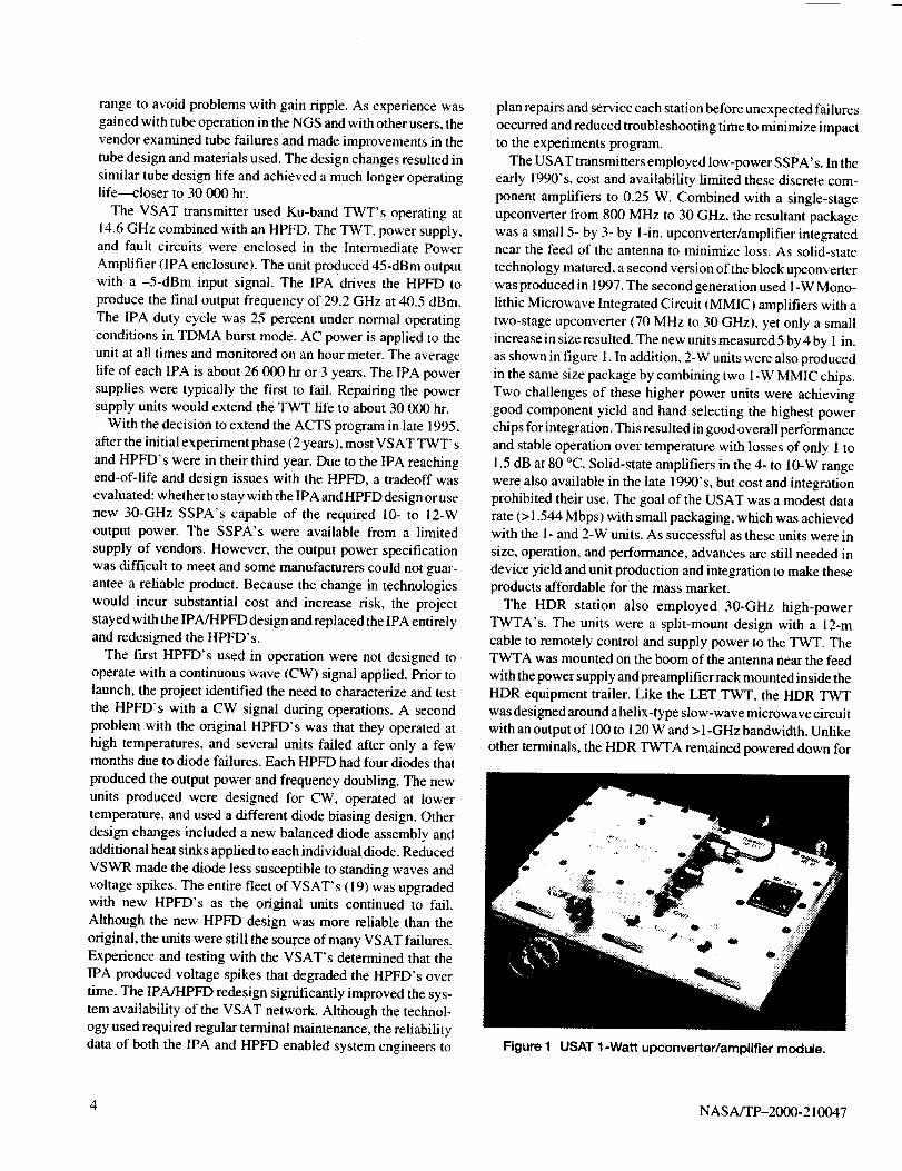
StationNGS
VSAT
USAT
HDR
LET
Technology54WattSingleChassis
150 Watt
TWTA-splitmount12 Watt Ku-
Band TWT,HPFD
.25-2 Watt
Solid State/
MMIC
120 Watt
TWTA-splitmount
60 Watt TWTA
Single Chassis
100 Watt
TWTA SingleChassis
Initial Issues
Sporadic shutdowns
RF power transients
Low reliabilityTWT failure at
10,000-12,000 hours
Cooling fans
HPFD reliability
Solid state andMMIC cost and
availability
Low reliability- Environmental
effects
Sporadic shutdowns
RF power transients
Low reliabilityNone
Advancements / Lessons Learned
Improved gun insulation and insulation application
procedure.
Modified tube design and operational changes led to>30,000-hour tube life with minimal service.
New HPFD diode and heat sink designTechnology gaps remain for affordable Ka-band10-12 Watt SSPA.
Single integrated block upconverter/amplifierAdvancements in MMIC made devices more
available.
Reduction in cost & integration required enablingconsumer terminals.
Identified potential high voltage interface issues of
outdoor installed split mount TWTAs.Environmental concerns remain for precision
tolerances required for Ka-band TWTA operation.
Improved gun insulation and insulation application
procedure.
Operational changes led to >22,000-hour tube lifewith minimal service.
Table 2 Transmitter Technology Summary
the majority of the time, as recommended by the TWTA vendor
(different from NGS and LET), despite the experience gained
in the NGS and LET operations. TWTA operations without
high voltage applied were limited to only a few minutes.
The TWTA used in the beginning of the project had an
extremely high failure rate. The high failure rate was attributed to
the following: (a) water penetrating the outdoor high-voltage
connectors and shorting out the power supply; (b) high-voltage
shotting out to chassis due to faulty potting; and (c) temperature
fluctuations causing the TWT to defocus. In addition to the failurerates, turnaround time on defective units was excessive. In mid-
1997, a different vendor was selected to provide TWTA for the
HDR project. TWTA performance and reliability improved.
Table 2 summarizes the transmitter technology used in each
ground station. A number of different approaches were taken
with each station because of experiment and application re-
quirements. Design changes in TWTA material and integra-
tion, changes to TWTA operation procedures, and advancements
by industry in solid-state and MMIC amplifiers were highlights
of this technology area.
Receiver
Receiver technology experienced modest advancements dur-
ing the ACTS program. The majority of LNA and low-noise
converters (LNC's) were built to specifications often at or
slightly in advance of state-of-the-art at the time. Most of the
devices used, with the exception of the VSAT LNC, were
technically good devices lasting for many years of service.
The NGS LNA employed quarter-micron HEMT FET, whichwere the state-of-the-art in the late 1980' s when the station was
built. Two sets of LNA are used: one at 20 GHz for the TDMA
downlink and telemetry beacons and one at 27.5 GHz for the
transmit band propagation beacon.
The 20-GHz LNA subassemblies are implemented in a
cascade of two stages, each with a gain of 30 dB and a noise
figure of 3.0 dB. The station employs three such LNA subas-
semblies in a redundancy configuration of three for two. The
total system noise temperature referenced to the antenna output
is 570 K. This value includes an antenna temperature of 123 K
and an effective system electronics temperature, including
waveguide loss, of 447 K.
The 27.5-GHz LNA also employ two stages each with a gain of
20 dB and a noise figure of 4.5 dB. The total system noise
temperature, referenced to the antenna output, is 1687 K. This
value includes an antenna temperature of 121 K and an effective
system electronics temperature, including waveguide loss, of1566 K.
The NGS LNA have been in nearly continuous operation,
either in test facilities or on the air, since 1991. They have
proven to be a robust technology. Few failures occurred over
their 9 years of operation, most explained by environmental
incidents, that is, periods of high ambient temperature due to
NASA/TP-2000-210047 5
facilityHVACfailuresorinadvertentsignaloverload,ratherthandevicefailure.Periodicmaintenancechecksindicatedlittleornodegradationindeviceperformanceovertheperiodofservice.
TheoriginalLET20-GHzreceiver/downconverterusedafour-stageHEMTLNAfollowedbyanMMICmixerandamplifierstagestodownconvertthesignalto anIF of 3 to4GHz.Therewerethreesuchunitsproducedunderaproof-of-concept(POC)developmenteffort. The LNA anddownconverterhadacombinednoisefigureofapproximately4to5.5dBwithanominalgainof25dB.WhilethePOCunitsexhibitedexcessivegainslopeacrossthefull I-GHzdownlinkband,theyexhibitedonlymodestgainslopeacrosstheiropera-tionalband(300MHz)andwerequiteusableforapplicationswithinthatbandwidth.Consequently,theywereincorporatedintotheinitialstationbuildupandusedforrelativelynarrowbandsignalapplicationsasanefficientuseofexistinghardwareandacost-savingsmeasureearlyin theprogram.However,becauseoftheirgainslopeacrossthefullband,thePOCunitsprovedunusableforwidebandapplicationssuchason-orbitlinkandspacecraftcharacterizationexperimentsoftheentiretransponderbandwidth,andemergingHDRmodemtechnol-ogyrequiringlargerbandwidthswithminimumgainslope.Toaccommodatethesewiderbandwidthapplications,it wasnec-essarytoreplacethePOCunitswithreceiverstailoredforthatpurpose.
TheLETreceiverswerereplacedwithcommerciallyavail-ableLNA'sandanin-house-designeddownconverter.TheLNA'sselectedwereidenticalto thoseusedin theHDRstations.TheLNAexhibitedanoisefigureof3.5dBand50dBofgainwithaminimalgainslopeacrosstheI-GHzband.TheLNAusedinHDRandLETprovedreliableovertheproject.Manyhavebeeninservicesince1995withlittleornoperfor-mancedegradation.Thefewfailuresthatdidoccurweremainlytheresultofphysicaldamagetotheamplifier.
TheVSATstationsencounteredsignificantchallengesinthereceiverdesignandperformance.TheVSATLNCisathree-stageHEMTLNA,RFbandpassfilter,mixer,siliconMMICIFamplifier,voltageregulator,andfaultcircuit.Developedintheearly1990's,thereceiversexhibitedawiderangeofperfor-mance.Thereceivergainwasspecifiedat45dB,andthenoisefigurewasspecifiedat5dB.Theperformancefromunittounitdifferedsignificantly.Eachunitwashandtunedatthefactoryasaresultoftheperformance.Thetotalreceivergain(multiplestages)ranged from 40 to 52 dB and the noise figure varied from
3 to 9 dB. These variations required that the downlink of each
station be adjustedto ensure like performance and operation
compared to other VSAT's. Because the receiver performancevaried so much between units, the entire receiver characteris-
tics drastically changed when different receivers were installed
due to failure or service. This lengthened the service time at a
particular station to allow time to make necessary adjustmentsto account for differences in the receivers.
The first-generation USAT ground stations that were used
combined LNA and single-stage block downconverters from 29GHz to 70 MHz. Performance, small size, and low cost were the
primary goals of the USAT low-noise downconverters (LND).
The original LND exhibited a 25- to 28-dB gain with a 4- to 4.5-
dB noise figure over a 40-MHz bandwidth. 4 The units measured
4.25 by 2.25 by 0.4 in. The LND could operate with 40-MHz
bandwidth increments from 19.7 to 20.4 GHz by varying the
downlink oscillator. The first-generation LND failed after 3 yearsof operation. Coincidentally, four of five units failed within the
same month after varying scenarios of operation. The fifth unitfailed a short time later. Each LND had a similar amount of
operation time but was often located in different geographical and
temperature locations. No particular operational parameter wasidentified as being the cause of these failures.
Improvements made by industry during the 1990's resulted
in improved performance for the second-generation LND.
With a similar size package, the new LND's had a 32-dB gainwith a 2- to 2.5-dB noise figure over a 50-MHz bandwidth. A
total of 15 units were purchased in 1997 with all units exhibiting
similar gain and noise figure performance. These units also
covered the 19.7- to 20.04-GHz spectrum but had larger receivebandwidths of 50 MHz (compared to 40 MHz). With the
improved noise figure, these units raised the available data rate
between small ground stations making them more adaptable toa variety of applications. 5
Antenna
All the antennas used with the transportable experimenterground stations were offset fed parabolic reflectors. The USAT
and VSAT reflectors were actually Ku-band reflectors, which
proved adequate for operation at Ka band. However, propaga-tion experiments conducted on the antennas revealed that wet
antenna effects of Ku-band antennas operating at Ka bandresulted in a greater loss due to the rainwater and the thickness
of the Ku-band dielectric. Minimizing the dielectric thickness
at Ka band is needed to reduce loss in the presence of water onthe reflector. 6 As much as 2 to 5 dB is lost due to wet antenna
and feed radome effects.
The HDR station was the only experimenter station antenna
in the ACTS program made up of individual panels. The USAT
and VSAT reflectors (0.6, 1.2, and 2.4 m) were all one-piece
structures. The 3.4-m HDR antenna was made up of four
individual panels. Station performance validated that using thistype of sectioned reflector is a viable alternative for Ka-hand
operation compared to a single piece reflector. Surface toler-
ance and feed alignment were adequate for operation.
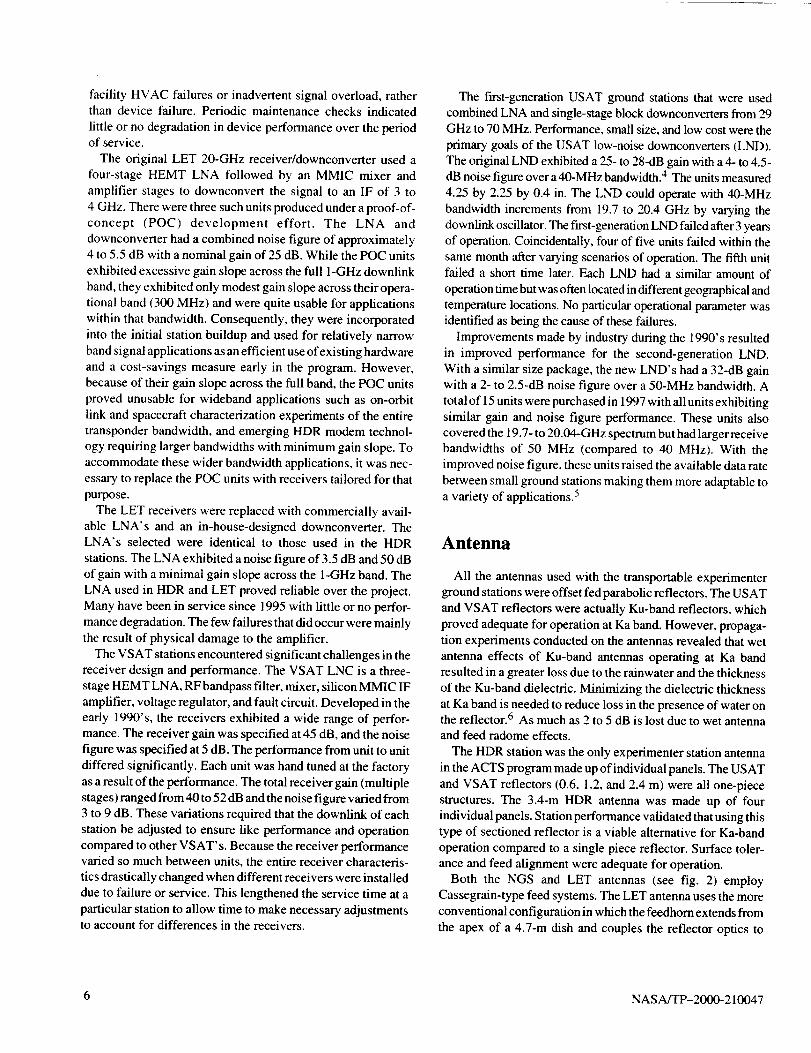
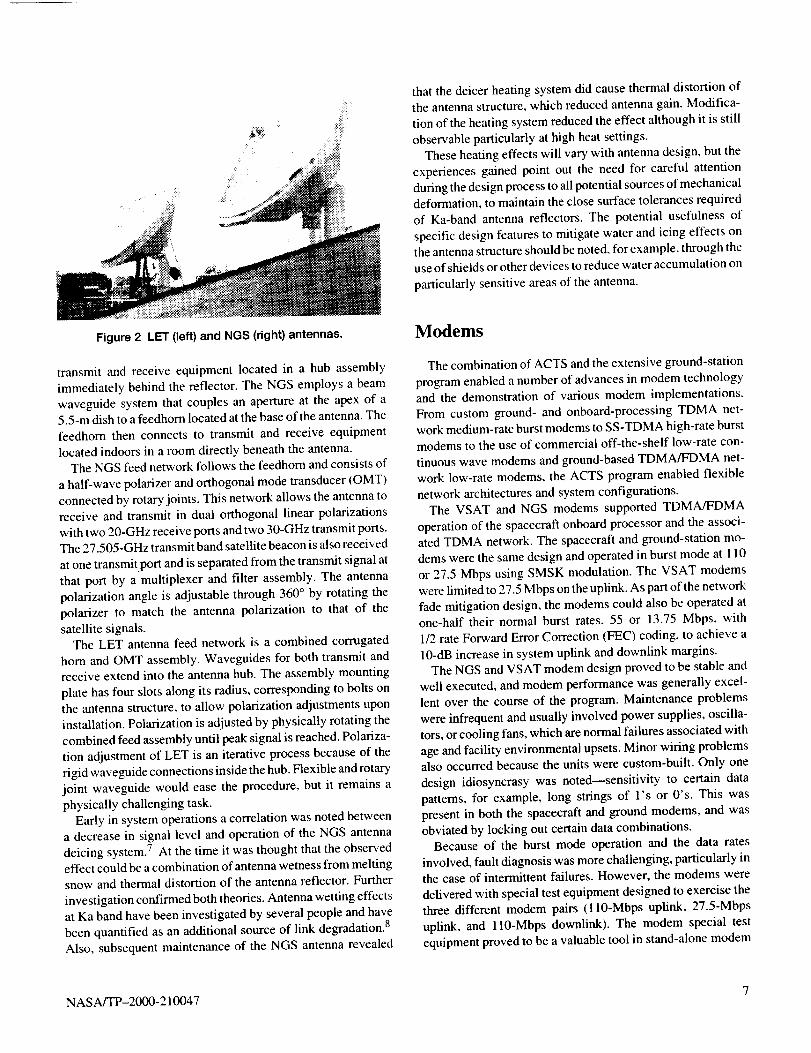
Both the NGS and LET antennas (see fig. 2) employCassegrain-type feed systems. The LET antenna uses the more
conventional configuration in which the feedhorn extends from
the apex of a 4.7-m dish and couples the reflector optics to
6 NASA/TP-2000-210047
thatthedeicerheatingsystemdidcausethermaldistortionof
the antenna structure, which reduced antenna gain. Modifica-
tion of the heating system reduced the effect although it is still
observable particularly at high heat settings.
These heating effects will vary with antenna design, but the
experiences gained point out the need for careful attention
during the design process to all potential sources of mechanical
deformation, to maintain the close surface tolerances required
of Ka-band antenna reflectors. The potential usefulness of
specific design features to mitigate water and icing effects on
the antenna structure should be noted, for example, through theuse of shields or other devices to reduce water accumulation on
particularly sensitive areas of the antenna.
Figure 2 LET (left) and NGS (right) antennas.
transmit and receive equipment located in a hub assembly
immediately behind the reflector. The NGS employs a beam
waveguide system that couples an aperture at the apex of a5.5-m dish to a feedhorn located at the base of the antenna. The
feedhorn then connects to transmit and receive equipment
located indoors in a room directly beneath the antenna.The NGS feed network follows the feedhorn and consists of
a half-wave polarizer and orthogonal mode transducer (OMT)
connected by rotary joints. This network allows the antenna to
receive and transmit in dual orthogonal linear polarizations
with two 20-GHz receive ports and two 30-GHz transmit ports.The 27.505-GHz transmit band satellite beacon is also received
at one transmitport and is separated from the transmit signal atthat port by a multiplexer and filter assembly. The antenna
polarization angle is adjustable through 360 ° by rotating the
polarizer to match the antenna polarization to that of the
satellite signals.
The LET antenna feed network is a combined corrugated
horn and OMT assembly. Waveguides for both transmit and
receive extend into the antenna hub. The assembly mounting
plate has four slots along its radius, corresponding to bolts on
the antenna structure, to allow polarization adjustments upon
installation. Polarization is adjusted by physically rotating the
combined feed assembly until peak signal is reached. Polariza-
tion adjustment of LET is an iterative process because of the
rigid waveguide connections inside the hub. Flexible and rotary
joint waveguide would ease the procedure, but it remains a
physically challenging task.
Early in system operations a correlation was noted between
a decrease in signal level and operation of the NGS antenna
deicing system. 7 At the time it was thought that the observed
effect could be a combination of antenna wetness from meltingsnow and thermal distortion of the antenna reflector. Further
investigation confirmed both theories. Antenna wetting effects
at Ka band have been investigated by several people and havebeen quantified as an additional source of link degradation. 8
Also, subsequent maintenance of the NGS antenna revealed
Modems
The combination of ACTS and the extensive ground-station
program enabled a number of advances in modem technology
and the demonstration of various modem implementations.
From custom ground- and onboard-processing TDMA net-
work medium-rate burst modems to SS-TDMA high-rate burstmodems to the use of commercial off-the-shelf low-rate con-
tinuous wave modems and ground-based TDMA/FDMA net-
work low-rate modems, the ACTS program enabled flexible
network architectures and system configurations.
The VSAT and NGS modems supported TDMA/FDMA
operation of the spacecraft onboard processor and the associ-
ated TDMA network. The spacecraft and ground-station mo-
dems were the same design and operated in burst mode at i 10
or 27.5 Mbps using SMSK modulation. The VSAT modems
were limited to 27.5 Mbps on the uplink. As part of the network
fade mitigation design, the modems could also be operated at
one-half their normal burst rates, 55 or 13.75 Mbps, with
1/2 rate Forward Error Correction (FEC) coding, to achieve a
10-dB increase in system uplink and downlink margins.
The NGS and VSAT modem design proved to be stable and
well executed, and modem performance was generally excel-
lent over the course of the program. Maintenance problems
were infrequent and usually involved power supplies, oscilla-
tors, or cooling fans, which are normal failures associated with
age and facility environmental upsets, Minor wiring problems
also occurred because the units were custom-built. Only one
design idiosyncrasy was noted--sensitivity to certain data
patterns, for example, long strings of l's or O's. This was
present in both the spacecraft and ground modems, and was
obviated by locking out certain data combinations.
Because of the burst mode operation and the data rates
involved, fault diagnosis was more challenging, particularly inthe case of intermittent failures. However, the modems were
delivered with special test equipment designed to exercise the
three different modem pairs (ll0-Mbps uplink, 27.5-Mbps
uplink, and 110-Mbps downlink). The modem special test
equipment proved to be a valuable tool in stand-alone modem
NASA/TP-2000- 210047 7
faultdiagnosis.However,it wasalsoincorporatedintothe
station test equipment suite so that the modems could be
exercised over the station transmit and receive paths to verify
overall station performance. Regular BER measurements were
performed as part of station periodic maintenance as a check on
both the modems and the amplitude and group delay character-
istics of the station transmit and receive equipment.
The HDR burst modem is a dual-mode device capable of
operating in offset binary phase-shift keying (OBPSK) or offsetquadrature phase-shift keying (OQPSK) modulation. The sym-
bol rate of the burst modem is 348 MS/s providing data rates of311 Mb/s in OBPSK or 622 Mb/s in OQPSK. Of the six
modems designed and built for the HDR program, three re-
mained in service and fully functional to the end of the inclined
orbit program operating for over 2 years without repair. Al-
though the modems performed soundly, it is believed the
addition of adaptive equalizers to the demodulator frontend to
compensate for the satellite nonlinear transponder and changes
in the system due to aging would have enhanced performance.
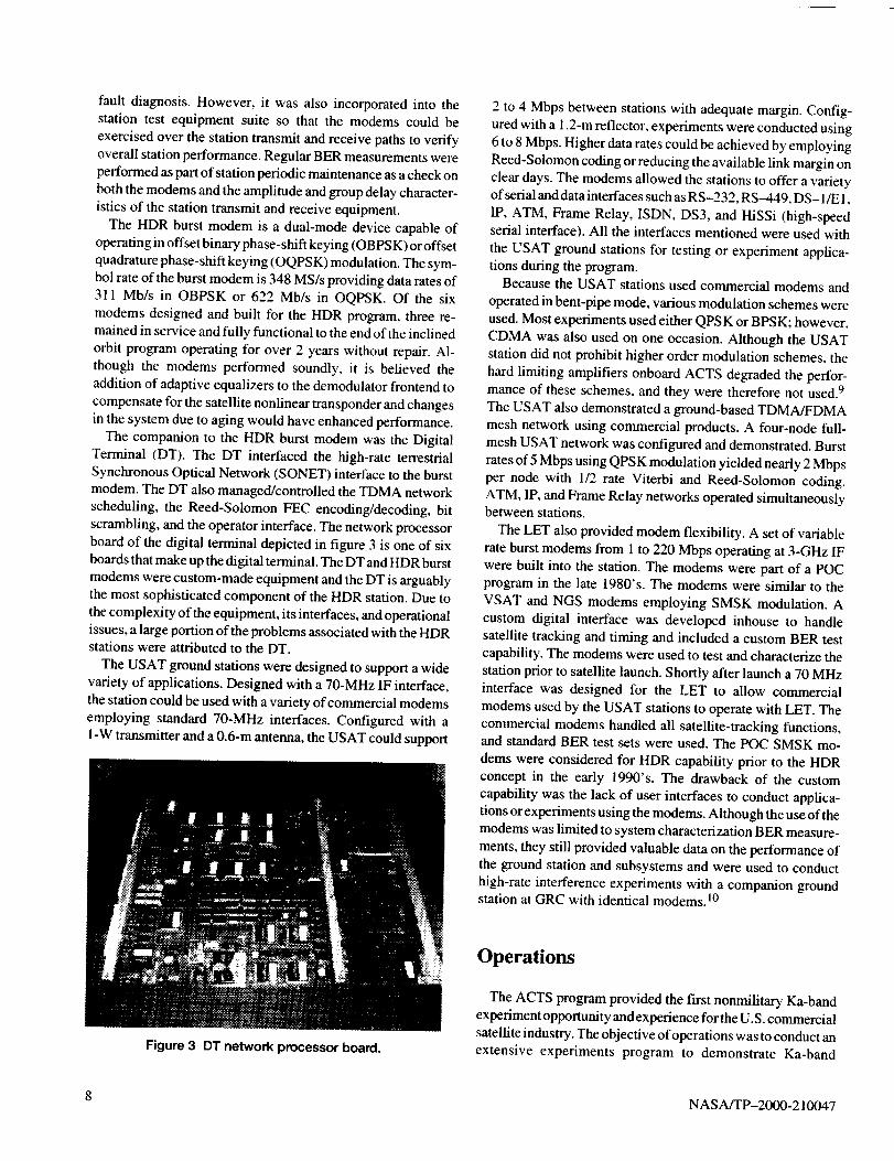
The companion to the HDR burst modem was the Digital
Terminal (DT). The DT interfaced the high-rate terrestrial
Synchronous Optical Network (SONET) interface to the burstmodem. The DT also managed/controlled the TDMA network
scheduling, the Reed-Solomon FEC encoding/decoding, bit
scrambling, and the operator interface. The network processor
board of the digital terminal depicted in figure 3 is one of six
boards that make up the digital terminal. The DT and HDR burst
modems were custom-made equipment and the DT is arguably
the most sophisticated component of the HDR station. Due to
the complexity of the equipment, its interfaces, and operational
issues, a large portion of the problems associated with the HDRstations were attributed to the DT.
The USAT ground stations were designed to support a wide
variety of applications. Designed with a 70-MHz IF interface,
the station could be used with a variety of commercial modems
employing standard 70-MHz interfaces. Configured with aI-W transmitter and a 0.6-m antenna, the USAT could support
2 to 4 Mbps between stations with adequate margin. Config-
ured with a 1.2-m reflector, experiments were conducted using
6 to 8 Mbps. Higher data rates could be achieved by employing
Reed-Solomon coding or reducing the available link margin on
clear days. The modems allowed the stations to offer a varietyof serial and data interfaces such as RS-232, RS-449, DS- 1/E 1,
IP, ATM, Frame Relay, ISDN, DS3, and HiSSi (high-speedserial interface). All the interfaces mentioned were used with
the USAT ground stations for testing or experiment applica-
tions during the program.Because the USAT stations used commercial modems and
operated in bent-pipe mode, various modulation schemes were
used. Most experiments used either QPSK or BPSK; however,
CDMA was also used on one occasion. Although the USAT
station did not prohibit higher order modulation schemes, the
hard limiting amplifiers onboard ACTS degraded the perfor-
mance of these schemes, and they were therefore not used. 9
The USAT also demonstrated a ground-based TDMA/FDMA
mesh network using commercial products. A four-node full-mesh USAT network was configured and demonstrated. Burst
rates of 5 Mbps using QPSK modulation yielded nearly 2 Mbpsper node with 1/2 rate Viterbi and Reed-Solomon coding.
ATM, IP, and Frame Relay networks operated simultaneouslybetween stations.
The LET also provided modem flexibility, A set of variable
rate burst modems from 1 to 220 Mbps operating at 3-GHz IFwere built into the station. The modems were part of a POC
program in the late 1980's. The modems were similar to the
VSAT and NGS modems employing SMSK modulation. A
custom digital interface was developed inhouse to handle
satellite tracking and timing and included a custom BER test
capability. The modems were used to test and characterize the
station prior to satellite launch. Shortly after launch a 70 MHz
interface was designed for the LET to allow commercial
modems used by the USAT stations to operate with LET. The
commercial modems handled all satellite-tracking functions,and standard BER test sets were used. The POC SMSK mo-
dems were considered for HDR capability prior to the HDR
concept in the early 1990's. The drawback of the custom
capability was the lack of user interfaces to conduct applica-
tions or experiments using the modems. Although the use of the
modems was limited to system characterization BER measure-
ments, they still provided valuable data on the performance of
the ground station and subsystems and were used to conduct
high-rate interference experiments with a companion groundstation at GRC with identical modems, l0
Figure 3 DT network processor board.
Operations
The ACTS program provided the first nonmilitary Ka-band
experiment opportunity and experience for the U.S. commercial
satellite industry. The objective of operations was to conduct an
extensive experiments program to demonstrate Ka-band
8 NASA/TP-2000-210047
operationandservicesandreduceperceivedrisktoKa-bandsatellitetechnologyandoperations.Theground-stationfleetwasanintegralpartof theexperimentsprogramprovidinglessonslearnedinterminalinstallationandoperation.Conduct-ingexperimentsandoperationsaroundthecountryentailedensuringsystemavailabilityandreliability,conductingremoteoperations,monitoringstationperformance,anticipatinghard-warefailures,andprovidingtestbedcapabilitiestoverifyandmaintainstationperformance.
TheVSATandHDRprojectshadthemostsophisticatedremoteoperationscapabilityof theexperimenterterminals.TheVSATreliedondedicateddial-upmodemaccesstoeachearthstationtoaccessstationcomputerstocontrolandconfig-urea hostof stationandTDMAnetworkparametersandmonitorstationBERperformance.TheHDRmanagementnetworkwasbasedontheSimpleNetworkManagementPro-tocol(SNMP)betweentheHDRnetworkmanagementtermi-nal(NMT,locatedat thecontrolcenter)andeachdigitalterminalfor theacquisitionprocess,terminalconfiguration,status,andcontrol.Thesystemincludedanover-the-satellite-signalingnetworkandbackupterrestrialInternet(IP-based)connectivity.TheUSATprojectuseddedicateddial-upaccessto queryandcontrolthecommercialmodem.USATstationparameterswerenotmonitoredremotely.All stationsuseddial-upcontrolforcyclingACpowertostationhardware.
TheVSAThasadatathroughputcapabilityof 1.792Mbpsdividedamongtheexperimenterandsystemneeds.Primarily,theexperimenterusedthefull 1.544MbpsorTI datarate(24channelsof64kbpseach)forexperimentactivitiesallowingfourchannelsforsystemandstationtesting,monitoring,andtroubleshooting.Of thefourchannels,theTDMAnetworkcomputerintheNGSusedtwo64-kbpschannelsforuplinkanddownlinkBERtesting,andonechannelwasusedforcallingintoeachearthstationtopolltheBERdatafromthestation.TheBERdatacollectedfromeachstationwasdownloadedtoadatabaseatthenetworkcontrolcenter.ThisBERversusEb/Nodatawascomparedtodailyweathermapstoanalyzerainfadeeventsandmonitorthestatusofeachearthstation.MonitoringandrecordingtheindependentuplinkanddownlinkBERofeachVSATstationallowedTDMAnetworksystempersonneltoobservetrendsinthedataindicatingpossibleequipmentdegra-dationorfailurebeforeit affectedtheexperimenter.
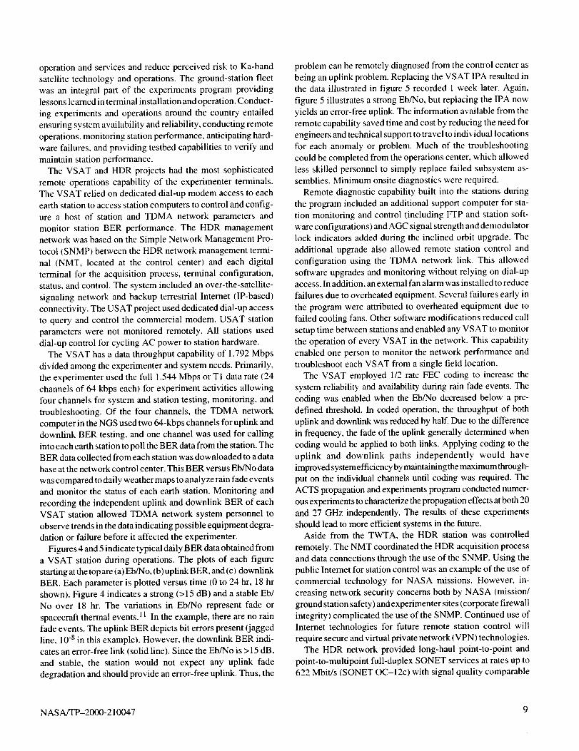
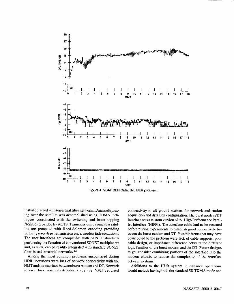
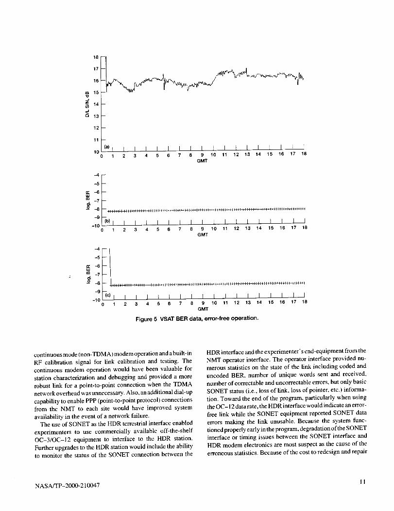
Figures4and5indicatetypicaldailyBERdataobtainedfromaVSATstationduringoperations.Theplotsof eachfgurestartingatthetopare(a)Eb/No,(b)upfinkBER,and(c)downlinkBER.Eachparameterisplottedversustime(0to24hr,18hrshown).Figure4indicatesastrong(>15dB)andastableEb/Noover18hr.Thevariationsin Eb/Norepresentfadeorspacecraftthermalevents.11Intheexample,therearenorainfadeevents.TheuplinkBERdepictsbiterrorspresent(jaggedline,10-8inthisexample).However,thedown[inkBERindi-catesanerror-freelink(solidline).SincetheEb/Nois>15dB,andstable,thestationwouldnotexpectanyuplinkfadedegradationandshouldprovideanerror-freeup[ink.Thus,the
problemcanberemotelydiagnosedfromthecontrolcenterasbeinganuplinkproblem.ReplacingtheVSATIPAresultedinthedataillustratedin figure5recorded1weeklater.Again,
figure 5 illustrates a strong Eb/No, but replacing the IPA now
yields an error-free uplink. The information available from the
remote capability saved time and cost by reducing the need for
engineers and technical support to travel to individual locationsfor each anomaly or problem. Much of the troubleshooting
could be completed from the operations center, which allowed
less skilled personnel to simply replace failed subsystem as-semblies. Minimum onsite diagnostics were required.
Remote diagnostic capability built into the stations during
the program included an additional support computer for sta-
tion monitoring and control (including FFP and station soft-
ware configurations) and AGC signal strength and demodulator
lock indicators added during the inclined orbit upgrade. The
additional upgrade also allowed remote station control and
configuration using the TDMA network link. This allowed
software upgrades and monitoring without relying on dial-upaccess. In addition, an external fan alarm was installed to reduce
failures due to overheated equipment. Several failures early in
the program were attributed to overheated equipment due to
failed cooling fans. Other software modifications reduced call
setup time between stations and enabled any VSAT to monitor
the operation of every VSAT in the network. This capability
enabled one person to monitor the network performance and
troubleshoot each VSAT from a single field location.
The VSAT employed 1/2 rate FEC coding to increase the
system reliability and availability during rain fade events. The
coding was enabled when the Eb/No decreased below a pre-defined threshold. In coded operation, the throughput of both
uplink and downlink was reduced by half. Due to the difference
in frequency, the fade of the uplink generally determined when
coding would be applied to both links. Applying coding to the
uplink and downlink paths independently would have
improved system efficiency by maintaining the maximum through-
put on the individual channels until coding was required. The
ACTS propagation and experiments program conducted numer-
ous experiments to characterize the propagation effects at both 20
and 27 GHz independently. The results of these experiments
should lead to more efficient systems in the future.Aside from the TWTA, the HDR station was controlled
remotely. The NMT coordinated the HDR acquisition process
and data connections through the use of the SNMP. Using the
public Intemet for station control was an example of the use of
commercial technology for NASA missions. However, in-
creasing network security concerns both by NASA (mission/
ground station safety) and experimenter sites (corporate firewall
integrity) complicated the use of the SNMP. Continued use ofInternet technologies for future remote station control will
require secure and virtual private network (VPN) technologies.The HDR network provided long-haul point-to-point and
point-to-multipoint full-duplex SONET services at rates up to622 Mbit/s (SONET OC-12c) with signal quality comparable
NASA/TP-2000-210047 9
8I17
¢= 15 zl
_ 14_i' ]i'°.j 111213 'l i i "'l
10 I I I I I I I I0 1 2 3 4 5 6 7 8 9 10 11 12 13 14 15 16 17 18
GMT
-4
-5
n- --614,1
m -7
-9
-10_)t t I I I I I I I I I I t I I I I I
1 2 3 4 5 6 7 8 9 10 11 12 13 14 15 16 17 18
GMT
-4
-5
re -6UJ
CO -7
o -8
-9
-100
(C) l I I I I I I I I I I t I I I I I I1 2 3 4 5 6 7 8 9 10 11 12 13 14 15 16 17 18
GMT
Figure 4 VSAT BER data, U/L BER problem,
to that obtained with terrestrial fiber networks. Data multiplex-
ing over the satellite was accomplished using TDMA tech-
niques coordinated with the switching and beam-hopping
facilities provided by ACTS. Transmissions through the satel-
lite are protected with Reed-Solomon encoding providing
virtually error-free transmission under modest fade conditions.
The user interfaces are compatible with SONET standards
performing the function of conventional SONET multiplexers
and, as such, can be readily integrated with standard SONETfiber-based terrestrial networks. ]2
Among the most common problems encountered during
HDR operations were loss of network connectivity with theNMT and the interface between burst modem and DT. Network
service loss was catastrophic since the NMT required
connectivity to all ground stations for network and station
acquisition and data link configuration. The burst modem/DT
interface was a custom version of the High Performance Paral-
lel Interface (HIPPI). The interface cable had to be reseated
before/during experiments to establish good connectivity be-
tween the burst modem and DT. Possible items that may have
contributed to the problem were lack of cable supports, poorcable design, or impedance difference between the different
logic families of the burst modem and the DT. Future designs
might consider combining portions of the interface into the
modem chassis to reduce the complexity of the interface
between systems.
Additions to the HDR system to enhance operationswould include having both the standard SS-TDMA mode and
10 NASA/TP-2000-210047
tn
r_
I'tL17
,+Lr" "M v'14
13
12
11
10(a) I
1
I I I I I I 1 I I I t I I t [ I ]2 3 4 5 6 7 8 9 10 11 12 13 14 15 16 17 18
GMT
-4 --
-5
w -6uJ
rn -7
-9
-100
(b) l I I I I I l I I L I I L I I I I I1 2 3 4 5 6 7 8 9 10 11 12 13 14 15 16 17 18
GMT
-4
-5
,,=,-6m -7
-9
-100
p
|;::::: :::; ',11]1t IIH4{.+ft+4{H+H4-H'4-+-14+'H44-H+i-H+ie4"-tr'I+ie_H_+H_444+44++{+{tH_4
(e) l I I I I I I I I I I I I I I I I I1 2 3 4 5 6 7 8 9 10 11 12 13 14 15 16 17 18
GMT
Figure 5 VSAT BER data, error-free operation.
continuous mode (non-TDMA) modem operation and a built-in
RF calibration signal for link calibration and testing. The
continuous modem operation would have been valuable for
station characterization and debugging and provided a more
robust link for a point-to-point connection when the TDMA
network overhead was unnecessary. Also, an additional dial-up
capability to enable PPP (point-to-point protocol) connections
from the NMT to each site would have improved system
availability in the event of a network failure.The use of SONET as the HDR terrestrial interface enabled
experimenters to use commercially available off-the-shelf
OC-3/OC-12 equipment to interface to the HDR station.
Further upgrades to the HDR station would include the abilityto monitor the status of the SONET connection between the
HDR interface and the experimenter's end-equipment from the
NMT operator interface. The operator interface provided nu-
merous statistics on the state of the link including coded and
uncoded BER, number of unique words sent and received,
number of correctable and uncorrectable errors, but only basic
SONET status (i.e., loss of link, loss of pointer, etc.) informa-
tion. Toward the end of the program, particularly when usingthe OC- 12 data rate, the HDR interface would indicate an error-
free link while the SONET equipment reported SONET data
errors making the link unusable. Because the system func-
tioned properly early in the program, degradation of the SONET
interface or timing issues between the SONET interface and
HDR modem electronics are most suspect as the cause of the
erroneous statistics. Because of the cost to redesign and repair
NASA/TP-2000-210047 11
theDTlate in the program, the systems were used"as is." Often,
resetting the SONET interface or rebooting the DT would
alleviate the problem.
From a system level, the basic USAT consisted of RF
electronics, power supply, antenna and mount, commercial
modem, and tracking controller. A support computer allowed
remote access to the tracking controller and modem. Due to the
simplicity of the stations, the USAT operations were relatively
easy compared to the other experimenter stations. The stations
were built to minimize cost and most resemble potential future
commercial terminals. Test ports and built-in diagnostic equip-
ment were not part of the USAT design. However, the use of
commercial modems provided adequate test capability using
the built-in CW or BER test capability. Dial-up access to each
USAT allowed ACTS network operators to remotely control
the modem for test configurations or obtain receive signal
characteristics provided by the modem (receive power, BER,
AGC, frequency offset, etc). Remotely controlling the USAT
modem allowed configuration changes between continuous
wave and modulated signals, data rate. and frequency changes.
A corresponding modem at the LET allowed full end-to-end
link analysis of remote USAT stations.
The USAT ground stations were generally used for experi-
ments on a short duration basis. The intermittent scheduling of
each station at varying locations made it difficult to trend
station performance for any length of time. Stations were
generally bench tested periodically to ensure operation when
deployed. Station and system designers must consider the cost
and necessity of implementing remote diagnostic capability
versus station complexity. For ACTS, the complexity of the
VSAT station and TDMA network fully warranted full remote
diagnostic capability. It was found to be invaluable for system
characterization, monitoring, and analysis in an experimental
system. In the case of USAT, the design simplicity allowed the
stations to operate without routine monitoring. The limited
remote diagnostics provided by the commercial modem proved
sufficient for reliable operations.
The NGS and LET are co-located in the same facility at GRCknown as the Master Ground Station (MGS). The MGS was
staffed on a 24-hr, 7-day basis and was the control center for
ACTS Operations. It is linked by terrestrial circuits with the
Lockheed Martin ACTS Spacecraft Operations Center (ASOC),
which provides spacecraft bus monitoring and control with theNGS providing the TT&C link to the spacecraft itself. A
redundant set of ASOC spacecraft monitoring and control
equipment is located in the MGS so that the spacecraft can also
be controlled entirely from the MGS.
MGS facilities include extensive automation and monitoring
capabilities for the NGS/LET stations, as well as for the entire
ACTS system, via satellite orderwire circuits and the terrestrialintemet. Status and controls are available at the two station
operation consoles for station RF and antenna systems, space-craft TT&C functions, and the ACTS BBP, HDR, and MSM
networks, including the spacecraft communications payload.
During most operations, one operator at the MGS and one at the
ASOC facility can operate the entire system. In addition to
system operations, station operators also perform data-
processing tasks for the enormous amounts of data collected
daily by the system.The extensive automation available could have allowed
unattended or remote operation. However, in practice it was
quickly found that while such automation was useful and good,
there is no replacement for a live operator onsite in main control
facilities. Protection of the considerable investment in space-
craft and ground system assets, and immediate service of
normal and extraordinary system needs including response to
system users, are best served with live around-the-clock staff-
ing. While relatively uncommon, there were several significant
occasions during the 7-year mission when incidents such as
facility roof leaks and air conditioning, power, computer, and
communication equipment faults were immediately handled
by the on-duty operator, minimizing system outages and con-taining potentially catastrophic equipment damage. The tradeoff
and cost of fully automated and call-in processes must be
compared with the value of immediate response times when
system availability and fault repair are considered. The ACTS
system and equipment, though designed as an experimental
system with limited redundancy, experienced excellent avail-
ability throughout the entire 7-year mission. This was due in
large part to the immediate availability of onsite support.System designers would do well to note this significant lessonlearned.
Integration
The integration of each ground station was unique to the
technology used and available during its development, costconsiderations, and common practice. Each field terminal and
gateway earth station had unique integration issues to resolve
or manage. Although the design and implementation of each
station is beyond the scope of this paper, examples of the
challenges or successes of each terminal are highlighted to
provide lessons learned for future Ka-band ground station and
system designers.
For the VSAT, the major challenge was the integration of theelectronics enclosure located at the feed of the antenna. The
enclosure contained the LNC, phase locked oscillator (PLO),
HPFD, voltage regulator, fault circuits, orthomode transducer,
feedhorn assembly, and various waveguide and filter assem-
blies both at 19 and 29 GHz. Experience with operating and
maintaining the station determined that the LNC was posi-tioned too close to the HPFD. As described earlier, the HPFD
operated at high temperature, even after redesign. The LNC
was installed directly above the HPFD exposing the receiver toexcessive heat without adequate air circulation or ventilation.
The excessive heat affected the receiver noise figure and gain,
decreasing the receiver sensitivity and increasing system noise.
12 NASA/TP-2000-210047
Combinedwithinconsistentreceiverperformance,theaddedheatfurthercomplicatedoperationsandadverselyaffectedperformance.To improve the design, the HPFD inside theelectronics enclosure could have been installed inside the IPA,
near the TWT. In that configuration the TWT could be moni-
tored for voltage spikes using protection circuits to protect the
HPFD input. This design change would have corrected two
problems: ( 1 ) heat adversely affecting the LNC and (2) addi-tional circuitry to protect the HPFD from TWT power fluctua-
tions (spikes). Due to implementation cost, the project used the
current configuration throughout the program. The link mar-
gins built into the systems were sufficient to conduct operations
without impact to experiments.
A second problem with the electronics enclosure was the
presence of moisture in the feedhorn and in the enclosure itself.
The feedhorn moisture was corrected by replacing the "O" ring
gaskets, using feedhorns with better window adhesive, and
pressure testing the membrane seal. The moisture inside the
enclosure was corrected by changing the feedhorns and seals,
changing the desiccant packs inside the unit, and replacing the
gasket inside the enclosure cover. The moisture inside the
enclosure damaged the various electronics inside. The HPFD
failed as moisture damaged the diodes. The LNC, PLO, and
voltage regulator performance were also affected by moisture.
The experience with the VSAT electronics enclosure illustrates
the need for careful moisture-proofing design in outdoor elec-
tronics and periodic maintenance of small but important details
such as feedhorn protective windows, O rings, and gaskets and
careful assembly.
A highlight of the NGS integration was extensive IF and RF
ioopback capability built into the NGS to permit off-the-air
performance verification of station transmit and receive pathsfor both TT&C and TDMA functions. These features were
useful for testing and fault isolation, particularly when used
with the modem test equipment. Also, since the ACTS BBP isa regenerative repeater, that is, the uplink cartier cannot be
observed on the downlink, they enabled link monitoring that
otherwise would not have been available. In practice; however,
the reliability of station equipment over the mission life was
very high, and aside from periodic maintenance checks and a
few troubleshooting episodes, the loopback features were rarely
used. However, the loopback paths were used extensively for
station characterization testing prior to launch.
The inclusion of a spacecraft simulator in the MGS station
test equipment proved to be more useful in practice than the
built-in loopback paths. The simulator is the engineering model
of the ACTS spacecraft communications package and contains
a single transponder with a baseband processor and microwave
switch matrix. The simulator is functionally equivalent to the
flight communications package. It was used as a testbed in the
development of the NGS and was then incorporated into the
station test equipment suite. Station transmit and receive pathswere connected to the simulator at both IF and RF. A VSAT
terminal located in the station was also connected to the
simulator to emulate a small TDMA network. The spacecraft
simulator allowed the NGS and VSAT to simulate BBP opera-
tions as a complete system, all within the station equipment.
Most importantly, it allowed network personnel to investigate
problems offline, with the spacecraft in use by MSM experi-
menters, thus, not requiring valuable spacecraft time for trouble-
shooting.
The integration, assembly, and maintenance of the USAT
stations, which consisted of only seven active components,
were relatively easy. The first-generation USAT (0.25-W
upconvener/amplifier) was configured using two enclosures.The first enclosure held the IF section of both the transmit and
receive and the first-stage uplink and reference oscillators. The
upconverter/amplifier, LND, and remaining oscillators wereinstalled in a second enclosure, The configuration made for
easy access to all components. Heat was dissipated through thebase of the aluminum enclosure and did not affect other
components. The drawback was the number of cables required
to interconnect both enclosures (Tx, Rx, ref LO, power) sincewith one enclosure mounted at the feed and the second on the
mount, the cables had to allow a small degree of movement for
station pointing and later inclined orbit satellite tracking.
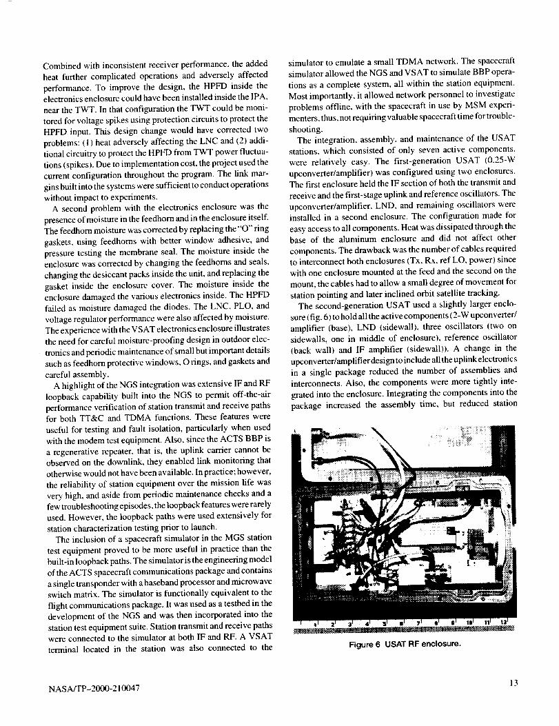
The second-generation USAT used a slightly larger enclo-
sure (fig. 6) to hold all the active components (2-W upconverter/
amplifier (base), LND (sidewall), three oscillators (two onsidewalls, one in middle of enclosure), reference oscillator
(back wall) and IF amplifier (sidewall)). A change in the
upconverter/amplifier design to include all the uplink electronic s
in a single package reduced the number of assemblies and
interconnects. Also, the components were more tightly inte-
grated into the enclosure. Integrating the components into the
package increased the assembly time, but reduced station
Figure 6 USAT RF enclosure.
NASA/TP-2000-210047 13
installationtimeandcomplexitybyeliminating one enclosure.
In both cases, the DC power supply used by the station was
separate from the electronics.
The LET was designed to evaluate the link between ground
station and satellite. Numerous test ports were designed into the
system such as receive, transmit (both before and after the
TWTA), loopback, calibration signal source, and all station
oscillators. Built-in test equipment provides power, frequency,
and spectrum measurement at each test port. Station modems
and built-in BER test system, described earlier, provide a
pseudorandom data source for detailed BER characterization.
Built-in Ioopback capability and RF connections to the MS M ofthe satellite simulator (ACTS transponder engineering model),
described earlier, proved valuable for offline system testing,
station checkout, and fault isolation. Access to test ports on
both uplink and downlink signal characteristics proved invalu-
able during system anomalies and characterization experiments.
As described earlier, LET station equipment was divided
between the antenna hub (directly behind the antenna reflector)
and an area directly below the roof under the antenna. The
receiver, TWTA, and portions of the upconverter are housed in
the hub, with the remaining components and all test equipment
located inside. An environmental control system and flexible
ductwork from the building to the antenna hub provided an
appropriate temperature-controlled environment for hub
electronics. The NGS beam waveguide antenna allowed all
transmit and receive equipment to be located indoors.
The LET electronics-in-hub configuration is the more eco-
nomical design, but is inconvenient to maintain when work is
required on the hub electronics, particularly in bad weather. A
small platform constructed on the back of the antenna structure
helped safety and stability, but accessing electronics inside the
hub was still difficult. The NGS beam waveguide design with
all equipment indoors allows easier and more immediate access
for maintenance and adjustments and direct access to antenna
input/output flanges for measurements and tests. The design
also allows implementation of more complex transmit/receive
systems and easier configuration changes. These features are
particularly well suited to experimental operations and in-orbit
test facilities. The disadvantage is the added expense of the
beam waveguide design. Station designers will need to weigh
the above factors against complexity required and intended
service in cost-benefit analysis of future designs.
Unlike the NGS and LET, the VSAT was not equipped with
loopback capabilities either at RF or IF. Lack of any loopback
capability made station testing difficult and relied upon the
TDMA network to evaluate station performance. Nonstandard
IF of 758 MHz (transmit) and 1620 MHz (receive) prohibited
loopback testing of the modems. Further, to contain costs, the
stations were not equipped with many test points. Test points in
both transmit and receive to measure various frequencies and
power levels throughout the system would have proved valu-
able and allowed easier alignment, troubleshooting, and testing
of the system.
The HDR stations were developed with TDMA Control Card
loopback (circuit card only), modem digital loopback (internal to
modem only), and IF loopback (external to modem). However,
the stations did not have an RF loopback capability. The loopback
functions were extremely useful to debug and test the ground
stations to isolate problems to either the digital terminal, the burst
modem, or to the RF system. RF Ioopback capability would have
been valuable to characterize individual station performance, but
again, cost and implementation must be considered.The electronics of the HDR station were divided between the
equipment trailer and the boom of the antenna. The upconverter
and downconverter electronics were installed in the equipmenttrailer with the LNA and TWTA mounted on the boom of the
antenna. As a result, both the transmit and receive paths had
approximately 12 m of waveguide between the equipmenttrailer electronics and the antenna feed electronics. The 750-MHz
bandwidth signals of the burst modems transmitted over these
long waveguide runs introduced crosstalk between the I and Q
channels of the OQPSK signal due to group delay dispersion of
the waveguide. 13 Custom waveguide equalizers with opposite
group delay were installed to mitigate the crosstalk and im-
prove station performance.
Inclined Orbit
By deleting the final north-south stationkeeping maneuver of
standard ACTS operations, ACTS experiment operations were
extended by operating in an inclined orbit. East-west
stationkeeping was maintained due to the small amount of fuel
required to execute east-west stationkeeping maneuvers. The
resulting orbital inclination increased at a rate of about 0.8 ° per
year, which made antenna tracking a requirement for all sta-
tions. Because of their aperture size, the LET and NGS antennas
already had existing tracking systems, which were used through-
out the ACTS program. Both systems operated in a step-
tracking mode using the 20-GHz telemetry beacon signal fromthe satellite. No modifications were made to the NGS-tracking
system. However, the LET-tracking system (and antenna) had
been developed under a POC contract more than 12 years
earlier. As with the LNA, the antenna and its tracker were put
into service without modification as a cost-savings measure.
Although the tracking system functioned technically well, a
new commercial system was installed to assure better system
availability (spare parts, current electrical equipment, etc.)
throughout the remaining program.
There were several impacts to the ground-station program that
resulted from inclined orbit operation. Each field station requirednew mounts and electronics to track the satellite. Also, the BBP
TDMA network and HDR network equipment required software
modifications to accommodate the increased range and range ratevariation in the inclined orbit. All modifications to the earth
stations were performed inhouse to reduce costs and to achieve
stringent pointing requirements for all stations.
14 NASA/TP-2000-210047
Becauseoftheincreasedrangeandrangeratevariationintheinclinedorbit,therewereimpactsontheBBPTDMAnetworkacquisitionprocess,whichpotentiallyrestrictedthetimesatwhichproperacquisitioncouldoccur.Tracking(oftiming)wasalsoaffected,whichlateinoperationsrestrictedthetimesthatsynchronizationcouldbemaintained.Thechangesweregradual;however,andoccurredaspredicted.Minorsoftwaremodifica-tionsweremadeto boththe VSAT and NGS software to
mitigate most of these effects, but complete mitigation would
have required additional software modifications to ground
equipment. Given the projected length of inclined orbit opera-tion, it was decided to work around the limitations when
necessary by modifying operating times and procedures. This
approach proved successful. No real limitations were encoun-
tered until very late in the program, as expected.
The HDR software system was expected to accommodate the
sate llite's increase in range rate and Doppler shift, but software
modifications were made to the acquisition process (range time
determination) algorithm. The initial round trip time (RTT)
was estimated based on the ground-station location and ephem-
eris data, with further RTT updates made once acquisition was
complete. After operating in inclined orbit, it was found that the
RTT software modifications functioned properly, but the in-
crease in range rate limited the times at which an HDR station
could acquire. Station acquisition was limited to the north and
south extremes of the satellite" s orbit. Once acquired: however,
the HDR stations maintained acquisition, even at the range rate
peak, through the center of the orbit. Review and analysis of the
HDR acquisition process revealed that the most likely cause of
the problem was a restriction in the acquisition software. Dueto cost and time to correct, the software was not modified.
Instead, the operations schedule was adjusted, with no impact
to station performance.
A commercial antenna-tracking controller was modified to
support remote configuration, control, and monitoring re-
quired by the field stations. The majority of system parameters
were programmable by dial-up modem or through support
computers using the existing station remote control capability.
The most significant feature implemented in the controller was
the ability to remotely upload and download the 24-hr history
and future movement of the antenna system. The ability toaccess and control this table allowed station personnel to
analyze ground-station position relative to satellite position
(download feature), program the antenna to move to predicted
positions in the case of a new installation (upload feature), or
repeat the past position for a specific time of day in the absence
of a received signal (memory track). Because of ACTS sched-
uling, the receive signal used by the VSAT and USAT stations
for closed-loop antenna tracking was not always available.
The memory track featured allowed the stations to use the lastknown position for a particular time slot. This feature main-
tained suitable pointing until the station was again scheduled
for experiments at which time the position table in memory
would update.
Each field terminal used the tracking controller for inclined
orbit operations. The controller required a 0- to 10-Vdc signal
input for closed-loop tracking. The memory table provided
open-loop tracking in the absence of a downlink signal. This
feature was often used due to ACTS scheduling of particular
earth stations. Each station addressed the closed-loop signal
requirement based on its system architecture and capabilities.
The VSAT used a feedback voltage from the automatic gain
control (AGC) card present within the VSAT as input to the
tracking controller. Minimal station design was required to
utilize the AGC feedback signal for the controller. However. to
ensure an accurate AGC feedback signal, the controller was
modified to accept a contact closure signal from the VSAT
indicating demodulator lock when synchronized with the BBP.
The AGC signal was only valid in this mode.Figure 7 illustrates a tracking signature of a VSAT 1.2-m
system compared to the NGS with both co-located at GRC. The
figure indicates accurate SAT tracking relative to the NGSreference with a maximum difference of<0.2 ° in either azimuth
or elevation, corresponding to <1 dB pointing loss.
Although the use of commercial modems gave the USAT
flexibility in modulation and data interfaces, the lack of a
digital interface posed a challenge for inclined orbit opera-
tions. To enable the USAT to track the satellite independently
of the modem used with the station, a separate circuit was
designed to provide the required analog input signal to the
tracking controller. Because the LND filtered the beacon
signal from the satellite, the analog signal was derived from the
70-MHz-received signal at the station. A series of narrow
bandpass filters and appropriate amplifiers followed by a
microwave detector followed by a narrow band digital filter
derived the required signal. The detector was operated in the
low-sensitivity region such that the voltage variation was
approximately linear with input power. Figure 8 illustrates a
typical tracking signature of a USAT with a 0.6-m reflector
compared to that of the NGS. Both are located at GRC. The
plot illustrates the ability of the USAT to follow the NGS
pattern from which satellite range and position data is verified.Also evident is the lack of resolution at the satellite location
extremes due to the larger beam width of the smaller USAT
aperture. Pointing error in the example is approximately 0.2 °azimuth and 0.4 ° elevation, which contribute approximately
l-dB pointing error loss.
Because the tracking signal was derived from the received
communications signal, the USAT antenna controllers were
configured to conduct their antenna peaking at alternating
intervals so that signal variations induced by uplink antenna
tracking did not confuse the downlink antenna-tracking pro-
cess ultimately causing both stations to mispoint.The USAT-tracking mount was an easily deployable termi-
nal with minimal impact to installation and little or no increase
in the overall terminal size once installed. Figures 9 and 10show the USAT mount before and after inclined orbit modifi-
cations, respectively. The fixed mount shown in figure 9 shows
NASA/TP-2000-210047 15
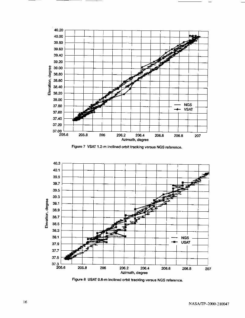
"O
[]
40.20
40.00
39.80
39.60
39.40
39.20
39.00
38.80
38.60
38.40
38.20
38.00
37.80
37.60
37.40
37.20
37.00205.6
NGS--e-- VSAT
205.8 206 206.2 206.4 206.6 206.8
Azimuth, degree
Figure 7 VSAT 1.2-m inclined orbit tracking versus NGS reference.
207
==
®1D
=-.o4-P
40.3
40.1
39.9
39.7
39.5
39.3
39.1
38.9
38.7
38.5
38.3
38.1
37.9
37.7
37.5
37.3
NGSUSAT--II--
205.6 205.8 206 206.2 206.4 206.6
Azimuth, degree
Figure 8 USAT 0.6-m inclined orbit tracking versus NGS reference.
206.8 207
16 NASA/TP-2000-210047
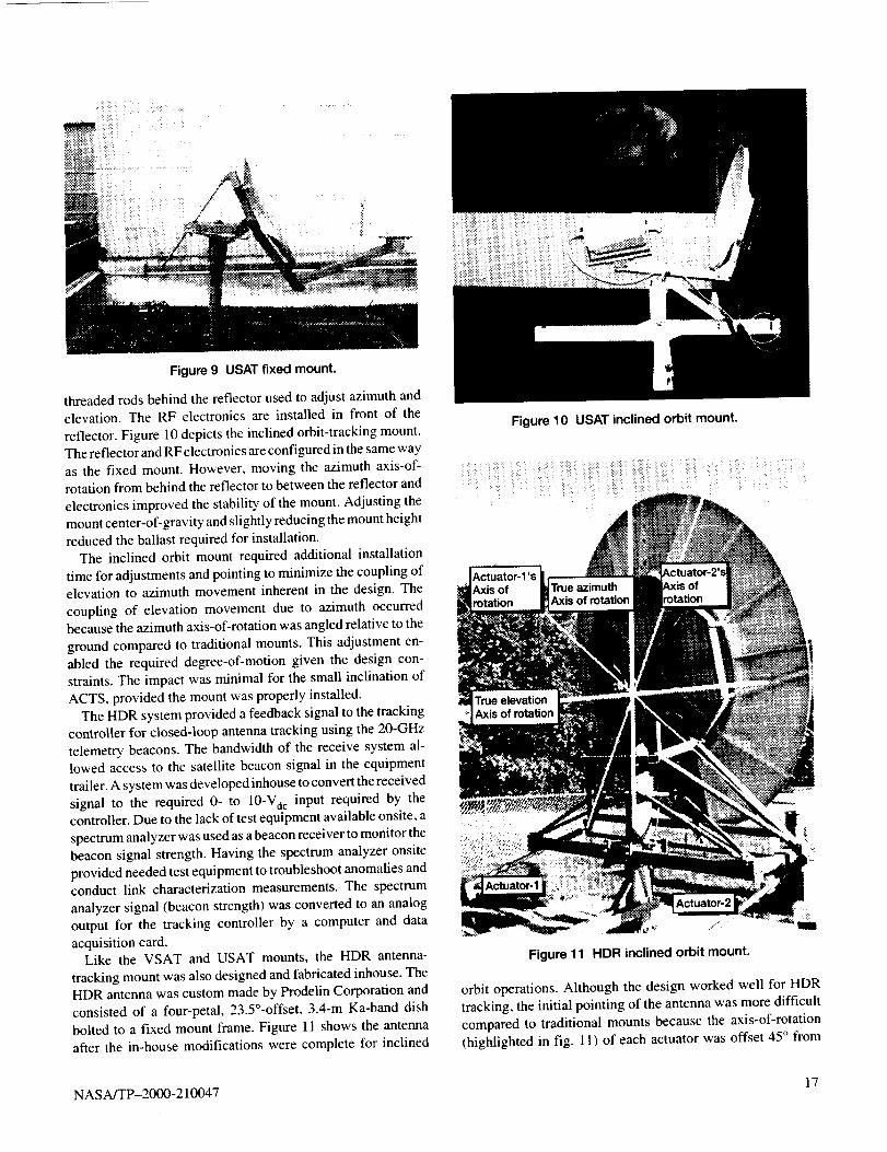
i:i!ii=iil:i : ilii i ¸ iil
Figure 9 USAT fixed mount.
threaded rods behind the reflector used to adjust azimuth andelevation. The RF electronics are installed in front of the
reflector. Figure 10 depicts the inclined orbit-tracking mount.
The reflector and RF electronics are configured in the same way
as the fixed mount. However, moving the azimuth axis-of-rotation from behind the reflector to between the reflector and
electronics improved the stability of the mount. Adjusting the
mount center-of-gravity and slightly reducing the mount height
reduced the ballast required for installation.
The inclined orbit mount required additional installation
time for adjustments and pointing to minimize the coupling ofelevation to azimuth movement inherent in the design. The
coupling of elevation movement due to azimuth occurred
because the azimuth axis-of-rotation was angled relative to the
ground compared to traditional mounts. This adjustment en-
abled the required degree-of-motion given the design con-
straints. The impact was minimal for the small inclination of
ACTS, provided the mount was properly installed.
The HDR system provided a feedback signal to the tracking
controller for closed-loop antenna tracking using the 20-GHz
telemetry beacons. The bandwidth of the receive system al-
lowed access to the satellite beacon signal in the equipmenttrailer. A system was developed inhouse to convert the received
signal to the required 0- to 10-Vetc input required by thecontroller. Due to the lack of test equipment available onsite, a
spectrum analyzer was used as a beacon receiver to monitor thebeacon signal strength. Having the spectrum analyzer onsite
provided needed test equipment to troubleshoot anomalies and
conduct link characterization measurements. The spectrum
analyzer signal (beacon strength) was converted to an analog
output for the tracking controller by a computer and data
acquisition card.Like the VSAT and USAT mounts, the HDR antenna-
tracking mount was also designed and fabricated inhouse. The
HDR antenna was custom made by Prodelin Corporation and
consisted of a four-petal, 23.5°-offset, 3.4-m Ka-band dish
bolted to a fixed mount frame. Figure 11 shows the antenna
after the in-house modifications were complete for inclined
Figure 10 USAT inclined orbit mount.
Figure 11 HDR inclined orbit mount.
orbit operations. Although the design worked well for HDR
tracking, the initial pointing of the antenna was more difficult
compared to traditional mounts because the axis-of-rotation
(highlighted in fig. 11 ) of each actuator was offset 45 ° from
NASA/TP-2000-210047 17
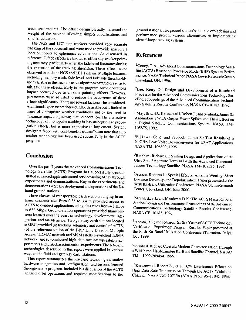
traditionalmounts.Theoffsetdesignpartiallybalancedthe
weight of the antenna allowing simpler modifications andsmaller actuators.
The NGS and LET step trackers provided very accurate
tracking of the spacecraft and were used to provide spacecraft
location inputs to ephemeris calculations. As discussed in
reference 7, fade effects are known to affect step tracker point-
ing accuracy, particularly when the fade level fluctuates during
the execution of the tracking algorithm. These effects were
observed in both the NGS and LET systems. Multiple features,
including memory track, fade level, and fade rate threshholds
are available in the trackers to set algorithm parameters so as to
mitigate these effects. Early in the program some operations
impact occurred due to antenna pointing effects. However,
parameters were adjusted to reduce the occurrence of these
effects significantly. There are several factors to be considered.
Additional experimentation would be desirable but is limited to
times of appropriate weather conditions and by the need to
minimize impact to gateway station operation. The alternative
technology of monopulse tracking is less susceptible to propa-
gation effects, but is more expensive to implement. System
designers faced with cost-benefits tradeoffs can note that step
tracker technology has been used successfully in the ACTS
program.
Conclusion
Over the past 7 years the Advanced Communications Tech-
nology Satellite (ACTS) Program has successfully demon-
strated advanced applications and services using ACTS through
experiments and demonstrations. Key to the experiments and
demonstrations were the deployment and operations of the Ka-
band ground stations.
Three classes of transportable earth stations ranging in an-tenna diameter size from 0.35 to 3.4 m provided access to
ACTS to conduct applications using data rates from 4.8 Kbps
to 622 Mbps. Ground-station operations provided many les-
sons learned over the years in technology development, inte-
gration, and maintenance. Two gateway earth stations located
at GRC provided (a) tracking, telemetry and control of ACTS,
(b) the reference station of the BBP Time Division MultipleAccess (TDMA) network and MSM satellite-switched TDMA
network, and (c) conducted high-data-rate interoperability ex-
periments and link characterization experiments. The Ka-bandtechnologies described in this report were applied in various
ways to the field and gateway earth stations.
This report summarizes the Ka-band technologies, station
hardware integration and configuration, and lessons learned
throughout the program. Included is a discussion of the ACTS
inclined orbit operations and required modifications to the
ground stations. The ground station's inclined orbit design and
performance present various alternatives to implementing
closed-loop-tracking systems.
References
IConey, T.A.: Advanced Communications Technology Satel-
lite (ACTS) Baseband Processor Mode (BBP) System Perfor-
mance. NASA Technical Paper, NASA Lewis Research Center.Cleveland, OH, 1996.
2Lee, Kerry D.: Design and Development of a Baseband
Processor for the Advanced Communications Technology Sat-
ellite. Proceedings of the Advanced Communication Technol-
ogy Satellite Results Conference, NASA CP-10183, 1996.
3May, Brian D.: Kerczewski, Robert J.; and Svoboda, James S.:
Anomalous TWTA Output Power Spikes and Their Effect on
a Digital Satellite Communications System. NASA TM-105875, 1992.
4Fijikawa, Gene; and Svoboda, James S.: Test Results of a
20 GHz, Low Noise Downconverter for USAT Applications.NASA TM-106892, 1995.
5Reinhart, Richard C.: System Design and Applications of the
Ultra Small Aperture Terminal with the Advanced Communi-
cations Technology Satellite. NASA TM-107536, 1997.
6Acosta, Roberto J.: Special Effects: Antenna Wetting, Short
Distance Diversity, and Depolarization. Paper presented at the
Sixth Ka-Band Utilization Conference, NASA Glenn Research
Center, Cleveland, OH, June 2000.
7Struharik, S.J.; and Meadows, D.N.: The ACTS Master Ground
Station Design and Performance. Proceedings of the Advanced
Communications Technology Satellite Results Conference,NASA CP-10183, 1996.
8Acosta, R.J.; and Johnson, S.: Six Years of ACTS Technology
Verification Experiment Program Results. Paper presented at
the Fifth Ka-Band Utilization Conference (Taormina, Italy),Oct. 1999.
9Reinhart, Richard C., et al.: Modem Characterization Througha Wideband, Hard-Limited Ka-Band Satellite Channel. NASA/
TM--1999-209454, 1999.
10Kerczewski, Robert K., et al.: CW Interference Effects on
High Data Rate Transmission Through the ACTS Wideband
Channel. NASA TM-107156 (AIAA Paper 96--1104), 1996.
18 NASA/TP-2000-210047
ItAcosta,RobertoJ.:AdvancedCommunicationTechnologySatellite(ACTS)MultibeamAntennaAnalysisandOn-OrbitPerformance.PresentedattheSecondKa-BandUtilizationConference(Florence,Italy),Sept.1996.
12Hoder,Douglas;andBergamo,Marcos:GigabitSatelliteNetworkforNASA'sAdvanced Communication Technology
Satellite (ACTS). Int. J. Satell. Commun., vol. 14, no. 3, 1996,
pp. 161-173.
13Kearney ' Brian; and Hoder, Douglas: High Data-Rate Ground
Station for the Acts Gigabit Satellite Network (GSN). Proceed-
ings of the Advanced Communication Technology SatelliteResults Conference, Part 1, NASA Lewis Research Center,
Cleveland, OH, 1996.
NASA/TP-2000-210047 19
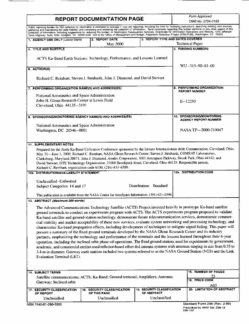
Form ApprovedREPORT DOCUMENTATION PAGE OMB No. 0704-0188
Public reporting burden for this collection of information is estimated to average 1 hour per response, including the time for reviewing instructions, searching existing data sources,
gathering and maintaining the data needed, and completing and reviewing the collection of information. Send comments regarding this burden estimate or any other aspect of this
collection of information, including suggestions for reducing this burden, to Washington Headquarters Services, Directorate for Information Operations and Reporls, 1215 Jefferson
Davis Highway, Suite 1204, Adiogton, VA 22202-4302, and to the Office of Management and Budget, Paperwork Reduction Project (0704-0188), Washinglon, DC 20503.
1. AGENCY USE ONLY (Leave blank) 2. REPORT DATE 3. REPORT TYPE AND DA]='-_ COVERED
May 2000 Technical Paper
4. TITLE AND SUBTITLE 5. FUNDING NUMBERS
ACTS Ka-Band Earth Stations: Technology, Performance, and Lessons Learned
6. AUTHOR(S)
Richard C. Reinhart, Steven J. Struharik, John J. Diamond, and David Stewart
7. PERFORMING ORGANIZATION NAME(S) AND ADDRESS(ES)
National Aeronautics and Space Administration
John H. Glenn Research Center at Lewis Field
Cleveland, Ohio 44135-3191
9. SPONSORING/MONITORING AGENCY NAME(S) AND ADDRESS(ES)
National Aeronautics and Space Administration
Washington, DC 20546- 0001
WU-315-90-81-4)0
8. PERFORMING ORGANIZATIONREPORT NUMBER
E-12250
10. SPONSORING/MONITORING
AGENCY REPORT NUMBER
NASA TP--2000-210047
11. SUPPLEMENTARY NOTES
Prepared for the Sixth Ka-Band Utilization Conference sponsored by the Istituto lnternazionale delle Comunicazion, Cleveland, Ohio,
May 3 l--June 2, 2000. Richard C. Reinhart, NASA Glenn Research Center; Steven J. Struharik, COMSAT Laboratories,
Clarksburg, Maryland 20871; John J. Diamond, Analex Corporation, 3001 Aerospace Parkway, Brook Park, Ohio 44142; and
David Stewart, GTE Technology Organization, 21000 Brookpark Road, Cleveland, Ohio 44 135. Responsible person,
Richard C. Reinhart, organization code 6130, (216) 433_588.
12a, DISTRIBUTION/AVAILABILITY STATEMENT
Unclassified - Unlimited
Subject Categories: 14 and 17 Distribution: Standard
This publication is available from the NASA Center for AeroSpace Information, (301J 621-0390.
12b. DISTRIBUTION CODE
13. ABSTRACT (Maximum 200 words)
The Advanced Communications Technology Satellite (ACTS) Project invested heavily in prototype Ka-band satellite
ground terminals to conduct an experiments program with ACTS. The ACTS experiments program proposed to validate
Ka-band satellite and ground-station technology, demonstrate future telecommunication services, demonstrate commer-
cial viability and market acceptability of these new services, evaluate system networking and processing technology, and
characterize Ka-band propagation effects, including development of techniques to mitigate signal fading. This paper will
present a summary of the fixed ground terminals developed by the NASA Glenn Research Center and its industry
partners, emphasizing the technology and performance of the terminals and the lessons learned throughout their 6-year
operation, including the inclined orbit phase-of-operations. The fixed ground stations used for experiments by government,
academic, and commercial entities used reflector-based offset-fed antenna systems with antennas ranging in size from 0.35 to
3.4 m in diameter. Gateway earth stations included two systems referred to as the NASA Ground Station (NGS) and the Link
Evaluation Terminal (LET).
14. SUBJECT TERMS
Satellite communications; ACTS; Ka-Band; Ground terminal; Amplifiers; Antenna;
Gateway; Inclined orbit
17. SECURITY CLASSIFICATIONOF REPORT
Unclassified
NSN 7540-01-280-5500
18. SECURITY CLASSIFICATIONOF THIS PAGE
Unclassified
19. SECURITY CLASSIFICATIONOF ABSTRACT
Unclassified
15. NUMBER OF PAGES
2516. PRICE CODE
A9320. LIMITATION OF ABSTRACT
Standard Form 298 (Rev. 2-89)Prescribed by ANSI Std. Z39-18
298-102
![4th Year - Deeniyat · khat kasheeda alfaaz mein kaun sa qaida hoga us par [P] ka nishaan lagaayein? 10 Tanween ka Idgaam. Tanween ka Ikhfaa. Tanween ka Izhaar Tanween ka Idgaam Tanween](https://img.pdfslide.us/doc/110x75/5f6039e7c988fa06d72aec6a/4th-year-deeniyat-khat-kasheeda-alfaaz-mein-kaun-sa-qaida-hoga-us-par-p-ka-nishaan.jpg)