Embed Size (px)
Citation preview

INN O VAT I O N mE A N S m OT I O N
pOlyAxIAl lOckINg SySTEm
DualTec System ®
ACTIVMOTIONHIgH TIbIAl OsTeOTOMy pl ATe
Anatomically contoured implant: proximal curvature and metaphyseal slope.Design and positioning perfectly adapted to the knee biomechanics.

INN O VAT I O N mE A N S m OT I O N
• ø4.5 mm reinforced core screws for optimal mechanical stability (progressive core diameter ø3.9 to 4.5 mm),
• Buried screws are used to minimize risks of soft tissue irritation.
FIxATION
HIgH TIBIAl OSTEOTOmy plATE
Anatomic asymmetrical implant (green anodized for right plate and blue anodized for left plate) Proximal curve Metaphyseal slope adapted to the anatomy 6 locking screws including 1 polyaxial screw Material: Titanium alloy
TEcHNIcAl FEATurES
AcTIVmOTION
Indications: The ACTIVMOTION range is indicated for high tibial osteotomy in adults.
Contra-indications: • Serious vascular deterioration, bone devitalization.• Pregnancy.• Acute or chronic local or systemic infections.• Lack of musculo-cutaneous cover, severe vascular deficiency touching the focus.• Insufficient bone quality preventing the correct insertion of the screws into the bone.• Muscular deficit, neurological deficiency or behavioural disorders, which could submit the implant to abnormal mechanical strains.• Allergy to one of the materials used or sensitivity to foreign bodies• Serious problems of non-compliance, mental or neurological disorders, failure to follow post-operative care recommendations.• Unstable physical and/or mental condition.
TeCHNICAl feATures pOlyAxIAl lOCkINg sysTeM 1 polyaxial locking hole (DTS®)
5 monoaxial locking holes (Oneclip®)
Possible angulation of the screw before locking (25° locking range) thanks to the DualTec System®.
25° degree cone
4
SElF lOckINg SySTEm
1
1
2
Results:
• Low profile construct:- The buried screw head thanks to the cap in the slot insuring the locking, (3)
- The screw head is buried in the plate (4).
• Construct limiting cold welding risks for improved removal properties: A perfect coaptation of both profiles when locking (5),
Features:
• The threaded sections under the screw head and inside the hole have strictly the same characteristics (1):
- Cylindrical internal thread profile,- Cylindrical external thread profile,• Screw head cap (2),• Plate and screw made from
the same material: titanium alloy.
3
5
INSTrumENTATION
A single instrument set for the whole ACTIVMOTION range, One type of screw (Ø4.5 mm) and one drill bit diameter (Ø4.0 mm) for simple and safe implant fitting, Osteotomy metallic wedges for progressive and safe opening of the osteotomy site.

B I O mEcH A NI cS O F T HE k NEE
MECHANICAL AXIS
INTERNAL STRESS = 100%
ANTERIOR VIEW
SAGITTAL VIEW
MECHANICAL AXIS
MEDIAL --
+3°
POSTERIOR --
LATERAL ++
ANTERIOR ++
STRESS DISTRIBUTION
STRESS DISTRIBUTION
MEDIAL ++
ANTERIOR VIEW
LATERAL --
SAGITTAL VIEW
MECHANICAL AXIS
POSTERIOR --ANTERIOR ++
STRESSDISTRIBUTION
NORMAL kNEE ALIGNMENT GENU VARUM
kNEE AfTER +3° VALGISATION CORRECTIONMECHANICAL AXIS
OPTIMAL IMPLANT POSITIONING. • The implant is fitted onto the antero-medial
surface of the tibia where the highest mechanical stress are registered.
• Screws are distributed following a 2 + 1 pattern: - 2 screws on the lateral tibial plateau - 1 screw on the medial tibial plateau
• Orientation of the screws in an antero-posterior direction allows for increased resistance to mechanical stress when the knee rolls back.

INN O VAT I O N mE A N S m OT I O N
S ur gI c A l T EcHNI q uE
surgICAl ApprOACH
2. An 8 cm slightly oblique vertical incision is made along the antero-medial surface, running over the joint space down to under the tibial tuberosity.
1. The patient is positioned supine on the operating table. The procedure is performed under pneumatic tourniquet and a small pillow is placed under the buttock of the operated side in order to maintain the limb in neutral rotation.
3. A single-plane incision is made through the periosteum; then the hamstring and the medial collateral ligament (MCL) are retracted posteriorly.
The larger the angular correction must be, the more the hamstring and MCL should be released distally.
4. An elevator is placed very carefully over the posterior surface of the tibial metaphysis and should remain in place as a protection during the osteotomy.
5. Clear the deepest part of the patellar tendon down to its attachment onto the tibial tuberosity, and protect it using a retractor during the osteotomy.
CAUTION : if the release is adequate, the opening of the osteotomy and the insertion of the bone graft can be performed with no risk of tearing the lateral cortical hinge. If it is not, forcing the graft in may tear the hinge, thus seriously jeopardizing complete bone mending.ie: pseudarthrosis.
1
2
HIgH TIbIAl OsTeOTOMy
B END IN g O F T HE p l AT E
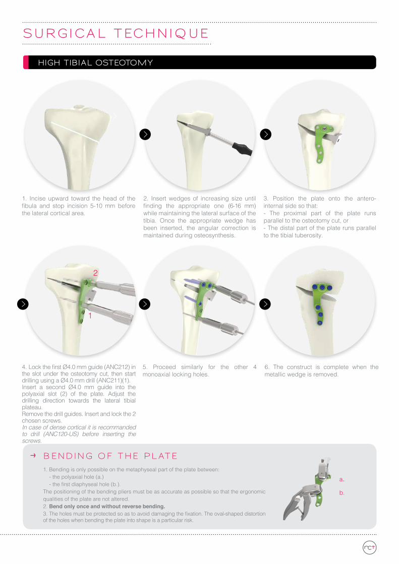
1. Bending is only possible on the metaphyseal part of the plate between:- the polyaxial hole (a.)- the first diaphyseal hole (b.).
The positioning of the bending pliers must be as accurate as possible so that the ergonomic qualities of the plate are not altered.2. Bend only once and without reverse bending. 3. The holes must be protected so as to avoid damaging the fixation. The oval-shaped distortion of the holes when bending the plate into shape is a particular risk.
a.b.
1. Incise upward toward the head of the fibula and stop incision 5-10 mm before the lateral cortical area.
2. Insert wedges of increasing size until finding the appropriate one (6-16 mm) while maintaining the lateral surface of the tibia. Once the appropriate wedge has been inserted, the angular correction is maintained during osteosynthesis.
3. Position the plate onto the antero-internal side so that: - The proximal part of the plate runs parallel to the osteotomy cut, or- The distal part of the plate runs parallel to the tibial tuberosity.
4. Lock the first Ø4.0 mm guide (ANC212) in the slot under the osteotomy cut, then start drilling using a Ø4.0 mm drill (ANC211)(1). Insert a second Ø4.0 mm guide into the polyaxial slot (2) of the plate. Adjust the drilling direction towards the lateral tibial plateau. Remove the drill guides. Insert and lock the 2 chosen screws.In case of dense cortical it is recommanded to drill (ANC120-US) before inserting the screws.
5. Proceed similarly for the other 4 monoaxial locking holes.
6. The construct is complete when the metallic wedge is removed.
S ur gI c A l T EcHNI q uE
INN O VAT I O N mE A N S m OT I O N
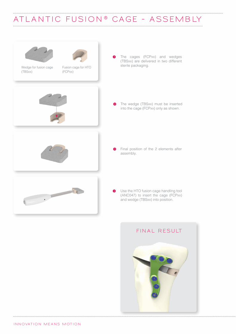
AT l A N T I c FuSI O N ® c A gE - A S SEmB ly
The cages (fCPxx) and wedges (TBSxx) are delivered in two different sterile packaging.Wedge for fusion cage
(TBSxx)fusion cage for HTO (fCPxx)
The wedge (TBSxx) must be inserted into the cage (fCPxx) only as shown.
final position of the 2 elements after assembly.
FIN A l r ES ulT
Use the HTO fusion cage handling tool (ANC047) to insert the cage (fCPxx) and wedge (TBSxx) into position.

Imp l A N TS r EFEr EN cES
OpENINg TIBIAl plATES*
Ref. DescriptionATDP1-ST Right opening tibial plate - size 1 - sterile
ATGP1-ST Left opening tibial plate - size 1 - sterile
ø4.5 mm DTS® SElF TAppINg ScrEwS*
Ref. DescriptionST4.5L30-ST DTS® self-tapping screw Ø4.5 mm - L30 mm - sterile
ST4.5L35-ST DTS® self-tapping screw Ø4.5 mm - L35 mm - sterile
ST4.5L40-ST DTS® self-tapping screw Ø4.5 mm - L40 mm - sterile
ST4.5L45-ST DTS® self-tapping screw Ø4.5 mm - L45 mm - sterile
ST4.5L50-ST DTS® self-tapping screw Ø4.5 mm - L50 mm - sterile
ST4.5L55-ST DTS® self-tapping screw Ø4.5 mm - L55 mm - sterile
ST4.5L60-ST DTS® self-tapping screw Ø4.5 mm - L60 mm - sterile
ST4.5L65-ST DTS® self-tapping screw Ø4.5 mm - L65 mm - sterile
ST4.5L70-ST DTS® self-tapping screw Ø4.5 mm - L70 mm - sterile
ST4.5L75-ST DTS® self-tapping screw Ø4.5 mm - L75 mm - sterile
ATlANTIc FuSION® cAgE AND wEDgE FOr FuSION cAgE rEFErENcES
ATlANTIc FuSION® cAgES*
Ref. DescriptionfCP06 fusion cage for HTO - 6 mm high
fCP08 fusion cage for HTO - 8 mm high
fCP10 fusion cage for HTO - 10 mm high
fCP12 fusion cage for HTO - 12 mm high
fCP14 fusion cage for HTO - 14 mm high
fCP16 fusion cage for HTO - 16 mm high
wEDgE FOr FuSION cAgES*
Ref. DescriptionTBS06 Wedge for fusion cage 6°
TBS08 Wedge for fusion cage 8°
TBS10 Wedge for fusion cage 10°
TBS12 Wedge for fusion cage 12°
TBS14 Wedge for fusion cage 14°
TBS16 Wedge for fusion cage 16°
* Sterile packaging
Manufacturer : BIOMATLANTE (FRANCE) Class : IIINotified body: TUV - 0123
Manufacturer : NEWCLIP TECHNICS (FRANCE) Class : IIbNotified body: SGS - 0120
Manufacturer : NEWCLIP TECHNICS (FRANCE) Class : IIbNotified body: SGS - 0120
Manufacturer : NEWCLIP TECHNICS (FRANCE) Class : IIbNotified body: SGS - 0120
ATDP1-STATGP1-ST

Broc
hure
EN
- Ac
tivm
otio
n - E
d.4-
04/
2015
- Re
ad la
belin
g an
d in
stru
ctio
ns b
efor
e us
e.
INST r umEN TS r EFEr EN cES
INSTrumENTS
Ref. Description QtyANC019 Metallic wedge 6 mm high 1
ANC020 Metallic wedge 8 mm high 1
ANC021 Metallic wedge 10 mm high 1
ANC022 Metallic wedge 12 mm high 1
ANC023 Metallic wedge 14 mm high 1
ANC024 Handle for metallic wedge and cutting guide 2
ANC025 Metallic wedge 16 mm high 1
ANC047 HTO fusion cage handling tool 1
ANC119-Sk 3.0 mm hexagonal screwdriver with quick coupling system 2
ANC120-US Ø4.2 mm reamer with US quick coupling system 1
ANC210 Length gauge for Ø4.5 mm screws 1
ANC211 Ø4.0 mm quick coupling drill bit 2
ANC212 Ø4.0 mm DTS® drill guide 2
ANC235 HTO Meary pliers 1
ANC240 Pliers for bending ACTIV plates 2
ANC312 3.0 mm quick coupling hexagonal screwdriver 1
ANC352 Ø6 mm US quick coupling handle 2
33.0222.150 k-wire -Trocar point/Round End - Ø2.2 L150 mm 3
The information presented in this brochure is intended to demonstrate a NEWCLIP TECHNICS product. Always refer to the package insert, product label and/or user instructions before using any NEWCLIP TECHNICS product. Surgeons must always rely on their own clinical judgment when deciding which products and techniques to use with their patients. Products may not be available in all markets. Product availability is subject to the regulatory or medical practices that govern individual markets. Please contact your NEWCLIP TECHNICS representative if you have questions about the availability of NEWCLIP TECHNICS products in your area.
Non
-con
tract
ual p
ictu
res.
INSERT (ANC279/I) BASE (ANC279/B)
rEmOVAl kIT
If you have to remove ACTIVMOTION implants, make sure to order the Newclip Technics removal set which includes the following instruments: - ANC119-Sk: 3.0 mm hexagonal screwdriver with quick coupling system- ANC352: Ø6 mm US quick coupling handle- ANC312: 3.0 mm quick coupling hexagonal screwdriver
NEWCLIP TECHNICSPA de la Lande Saint Martin - 45 rue des Garottières44115 Haute Goulaine (France)Tél. : +33 (0)2 28 21 37 12 - Fax : +33 (0)2 40 63 68 [email protected] - www.newcliptechnics.com
NEWCLIP USA642 Larkfield Center Santa Rosa CA 95403, USAPhone : + 1 707 230 [email protected] - www.newclipusa.com
![MM PAPER-1 PCM MM Roll No. AA€¦ · 1-AA ] [ 3 ] [ P.T.O. MM MM MM MM MM MM MM MM MM MM MM MM MM 002. Two children Ramesh (on path ARB) and Sohan (on path ASB), travel down slides](https://img.pdfslide.us/doc/110x75/5ec3c826fba71a6bb225c6e3/mm-paper-1-pcm-mm-roll-no-aa-1-aa-3-pto-mm-mm-mm-mm-mm-mm-mm-mm-mm-mm.jpg)