Embed Size (px)
Citation preview

Activity in the FID Detection Port: A Big Problem if UnderestimatedJaap de Zeeuw, Restek Corporation, Middelburg, The Netherlands
It is commonly known in gas chromatography, that many problems can be traced to the injection system (e.g. sample, syringe, inlet), which is often a primary place to look at possible issues. This is a valid statement, as 80% of “trouble” is related to injection conditions. One must also be aware that activity may be caused by other contributions. For instance, if we look at non-symmetrical peaks, there are more important area’s to look at. Not only the columns used can be overloaded or poorly deactivated, also the contribution of the detector has a huge impact on peak shape and response.Here it is shown that flame tips can adsorb up to 90% of component and cause tailing on polar as well as base/acidic components. Though it looks columns are not performing, it’s the detector that is the problem.
IntroductionThere is an ongoing need to measure lower levels of components in different kind of matrices. Often, troublesome components are more polar in nature, which challenges the analysis further, especially if lower concentrations are to be reported. In addition, in most labs, the user is given less time to optimize systems. Chromatography knowledge is fading and this is becoming an increasing challenge. It’s all about eluting and measuring a correct chromatographic peak.
Such a peak should look like a Gaussian curve. Any deformation from this curve is caused by an anomaly in the sampling and separation processes. The peak shape for a component in a typical GC can be affected in three ways:
• Injection and focusing• Separation• Detection
Injection and focusingAs stated before, 80% of “problems
Figure 1
Figure 1: Impact of column activity on peak height.

in GC” are caused by injection issues. Users need to understand the processes occurring in the injection port. These processes depend from the technique used. In splitted injection, the sample evaporates quickly and injection, evaporation, homogenization and splitting must be performed in a fraction of a second. Any interaction with liners, glass wool or residual septum particles will slow down the injection and peak shape will be affected. Split liners usually are narrow to get high speed and optimal splitting conditions. Because
the injection is performed as a narrow band, a focusing effect is not required. This is different when using the splitless, cold on-column or large volume injection techniques. Concentrations are lower and as the injection takes a longer time to get the components onto the column, there is also more time to interact.
SeparationThe separation pathway is very long, depending on the column used. Within the column, any residual active sites will deform the ideal
Figure 2
Figure 2: Impact of column activity on retention time of a polar analyte on columns with different deactivations.
Figure 3
Figure 3: A 30 m x 0.25 mm Rxi-5Sil MS column installed in correct position in the detector. Peaks are symmetrical and show correct response.
peak shape. Figure 1 shows what can happen when activity is present. Peaks start to become lower in height (lower sensitivity) and when they look like “shark-fins” we can expect impact on retention also. The retention time for a strong tailing peak depends on two mechanisms:1. Gas liquid interaction, which is responsible for the “normal” retention.2. Activity interaction, which is a different retention mechanism, based on adsorption. The degree of activity makes a peak elute at the “wrong” position.
An example is shown in Figure 2 where the same amount of alcohol is injected on different PONA columns. On a poorly deactivated surface, the alcohols elute at completely different retention times, due to activity. Only a proper deactivation makes sure alcohols elute at similar expected positions.
DetectionThe purpose of a detector is to detect the components. Usually the detector is set 10-20 ºC above the highest oven-temperature we use to elute the analytes from the column.
Sometimes detector temperatures are set above the maximum temperature of the stationary phase. For instance, polyethylene glycols will not be suitable at a temperature above 270 ºC: they will decompose rapidly forming activity. One must be very careful with that especially after reading the next paragraphs. How important is correct installation at the detection port? In the detector, there is always some distance between the end of the column and the actual detection. What can happen here? Looking in the literature there is very little
experimentation to find. It seems that activity at the end of the GC system is often neglected. Here we discuss the detector, but the same is also true for transfer lines, valves, connectors, flow-switching devices etc. Columns and transfer lines can develop high activity, just in standby position. This happens with any detector, where the carrier pressure is stopped and the detector gas-flows and temperatures are still high. For a FID, this is a big challenge and reason for doing some testing. What happens inside FID liner if you
Figure 4
Figure 4: Positioning the column outlet 1 cm lower in the 6890 FID, a big difference in response is observed. Also peak tailing starts to develop.
Figure 5
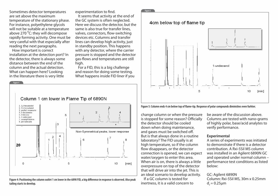
Figure 5: Column ends 4 cm below top of flame-tip. Response of polar compounds diminishes even furhter.
change column or when the pressure is stopped for some reason? Officially the detector should be cooled down when doing maintenance, and gases must be switched off. But is that always done in a routine laboratory? The FID usually is at high temperature, so if the column flow disappears, or the detector connection is opened, we can expect water/oxygen to enter this area. When air is on, there is always a little overpressure on top of the detector that will drive air into the jet. This is an ideal scenario to develop activity. If a GC column is tested for inertness, it is a valid concern to
be aware of the discussion above. Columns are tested with nano-grams of highly polar, base/acid analytes to verify performance.
ExperimentalA series of experiments was initiated to demonstrate if there is a detector contribution. A Rxi-5Sil MS column was installed in an Agilent 6890N GC and operated under normal column – performance test conditions as listed below:
GC: Agilent 6890NColumn: Rxi-5Sil MS, 30m x 0.25mm df = 0.25μm

Oven: 135 ºCCarrier gas : He, 22.9 psi, constant flowInjection: split, 200 mL/min, 0.6 μlTemp: 250 ºCSample: test mixture for Rxi column performance testingDetector: FID, temp. 300 ºC
The column was installed according to the manual: the column end positioned 1-2 mm from the top of the flame tip. We analysed the test mixture and obtained the chromatogram shown in Figure 3. The chromatogram looked as expected, with good response and good peak shapes. This became our
“baseline” chromatogram. Now we cooled the oven to 40 ºC, slightly opened the detector connection and pulled the column back proximate 10 mm. The connection was sealed again and oven temperature was restored. Figure 4 showed the impact of the 10 mm lower positioning of the column outlet in the FID. The last 10 mm of the FID caused a reduction in response for the polar analytes of almost a factor of 2. Note the response relative to peak 5 (tridecane). Also, significant tailing develope on the polar compounds 2,6-hexane diol, 4-chlorophenol,
1-decylamine and undecanol. No column would pass QA if it showed this behaviour. The last 10 mm of the flame tip in the 6890 was highly activated causing huge adsorption and loss of many components. To maximize impact of the detector the column was placed 4 cm lower in the detector. This would not be very realistic, but it provides a good example on what happens in the last 40 mm of transport. The problems increased significantly, (see Figure 5). As detectors are also used at lower temperatures, the temperature was lowered to 250 ºC. Now we see almost a loss of 85-90% response
(see Figure 6). The next step was to reinstall the column to the correct position. Figure 7 shows the chromatogram. The response was restored completely, demonstrating again the importance of correct position of the column outlet during installation.
Other systemsWe also checked an old HP-5890 system we use in our lab. Here another column was installed at different positions in the detector. Remarkably in this intance the position of the column in the detector did not make any difference
Figure 6
Figure 6: FID- detector cooled down from 300 to 250 ºC. Significant loss of response for polar compounds, caused by increased activity at lower temperature.
Figure 7
Figure 7: Column re-positioned near flame tip when detector was at 250 ºC. System performance is completely restored.

Figure 8: Standard test in HP-5890 GC using correct (black) and challenging (red) positions for column outlet. System response is perfect.
Figure 8
Comparison: correct installation and 5 cm below flame tip in old HP-5890
Figure 9
Figure 9: Example of SS and Siltek deactivated flame tips for agilent FID.
at any or temperature tested. Even when the column was cut 1 cm above the ferrule, the resulting chromatograms were very similar, see (Figure 8). The only difference with the newer systems, is the length of the FID-jet. The newer 6890 FIDs have a much shorter jet. However, this cannot explain the big differences observed. The activity /reactivity of the flame tip in FID always depend on the moment and can occur in any brand of GC. One can replace the flame tip
for special deactivated ones (there are Siltek deactivated tips available, see Figure 9), but activity in detection systems can also often be “masked” by conditioning columns at the upper temperature as some bleed products are formed. These bleed products can deactivate the detector, so it will perform OK. This “conditioning-deactivation” is a known method for deactivating transfer lines and traps for example, in SCLD and MS systems. Also one can assume when a GC
is used with adsorption columns (alumina, silica, porous polymers, charcoal or molecular sieves), it can be possible that some ‘dust’ particles will be retained in the flame tip. Such particles are highly active.
ConclusionFor good GC we need a fully inert gas path. Activity can be present not only in the injector and the column, but also in the detector. For many it may seem trivial to install columns the “correct” way; however, practically the importance of the position of column in a FID detector is underestimated. If detection ports are well deactivated, one will see no measurable impact. In contrast, if there is activity developing, only a
few millimeters of contact with the sample gas-path may lead to loss of components.The use of inert liners and inert columns, but for best results, one needs to be aware why columns are to be installed in the certain positions in injection and detection systems.
References1] J. de Zeeuw, R.Lautamo, G.Stidsen, C.English and S,Reese, American Lab, Vol. 40, nr.12, p.11-15.
This article was written by Jaapde Zeeuw. Jaap is a GC specialistworking for Restek.