Embed Size (px)
Citation preview
www.bonfiglioli.com
Bonfiglioli Riduttori S.p.A.Via Giovanni XXIII, 7/A40012 Lippo di Calderara di RenoBologna, Italy
tel: +39 051 647 3111fax: +39 051 647 [email protected]
VEC 557 R0
ACTIVE CUBEApplication manual - Crane drivesBrake control and load detectionConfigurations 160, 260 and 460
Bonfiglioli has been designing and developing innovative and reliable power transmission and control solutions for industry, mobile machinery and renewable energy applications since 1956.


110/07 10/07 1
General points on the documentation
The present documentation supplements the manual for hoisting and lift applications with extended brake control and the function for automatic load detection. The ap-plication manual documents the additional functionality of the frequency inverter in the software configurations 160, 260 and 460. These configurations extend the con-figurations 110, 210 and 410, which are described in the associated manual.
For better clarity, the user documentation is structured according to the customer-specific demands made of the frequency inverter.
Brief instructions The brief instructions “Quick Start Guide” describe the fundamental steps for me-
chanical and electrical installation of the frequency inverter. The guided commission-ing supports you in the selection of necessary parameters and the software configu-ration of the frequency inverter.
Operating instructions The operating instructions document the complete functionality of the frequency
inverter. The parameters necessary for specific applications for adaptation to the application and the extensive additional functions are described in detail.
Application manual The application manual supplements the documentation for purposeful installation
and commissioning of the frequency inverter. Information on various subjects con-nected with the use of the frequency inverter are described specific to the applica-tion.
Installation InstructionsComplementing the Brief Instructions and the Operating Instructions, the Installation Instructions provide information on how to install and use the additional/optional components.
The documentation and additional information can be requested via your local repre-sentation of the firm of BONFIGLIOLI. The following pictograms and signal words are used for the purposes of the present documentation:
Danger!means a directly threatening danger. Death, serious damage to persons and consid-erable damage to property will occur if the precautionary measure is not taken.
Warning!marks a possible threat. Death, serious damage to persons and considerable dam-age to property can be the consequence if attention is not paid to the text.
10/0722 10/07
Caution!refers to an indirect threat. Damage to people or property can be the result.
Attention!refers to a possible operational behavior or an undesired condition that can occur in accordance with the reference text.
Notemarks information that facilitates handling for you and supplements the correspond-ing part of the documentation.
Warning! In installation and commissioning, comply with the information in the documentation. You as a qualified person must read the documentation carefully before the start of the activity and obey the safety instructions. For the purposes of the instructions, "qualified person" designates a person acquainted with the erection, assembly, commissioning and op-eration of the frequency inverters and possessing the qualification corre-sponding to the activity.
310/07
10/07 3
Table of contents
1 General safety and application information .................................................................. 4 1.1 General information................................................................................................. 4 1.2 Proper use................................................................................................................ 4 1.3 Transport and storage ............................................................................................. 5 1.4 Handling and positioning......................................................................................... 5 1.5 Electrical connection................................................................................................ 5 1.6 Operation information ............................................................................................. 5 1.7 Maintenance and upkeep......................................................................................... 5
2 Technical data ................................................................................................................ 6 2.1 Requirements .......................................................................................................... 6 2.2 Control inputs and outputs...................................................................................... 7
2.2.1 VCB frequency inverter series ................................................................................... 7 2.2.2 ACU frequency inverter series ................................................................................... 8
3 Commissioning of the frequency inverter...................................................................... 8 3.1 Switch mains voltage on.......................................................................................... 8 3.2 Setup with the control unit...................................................................................... 9
4 Activation of a holding brake ....................................................................................... 10 4.1 Control inputs and outputs.................................................................................... 10
4.1.1 Digital outputs....................................................................................................... 10 4.2 Sequence control ................................................................................................... 11
4.2.1 Current monitoring ................................................................................................ 12 4.2.2 Frequency monitoring ............................................................................................ 12 4.2.3 Starting the drive................................................................................................... 13 4.2.4 Stopping the drive ................................................................................................. 14 4.2.5 Interrupting the start or stop process ...................................................................... 15 4.2.6 Occurrence of a malfunction ................................................................................... 15
5 Load detection for hoist application and luffing jib cranes ......................................... 16 5.1 Load detection for hoist application...................................................................... 16
5.1.1 Mechanical time constant ....................................................................................... 17 5.1.2 Turns per meter .................................................................................................... 18 5.1.3 Load estimate ....................................................................................................... 19 5.1.4 Speed switch-off limit............................................................................................. 20
5.2 Load detection for luffing jib cranes ..................................................................... 21 5.2.1 Torque-forming current Isq .................................................................................... 23
5.3 Limitation of the speed by fixed frequencies ........................................................ 25 5.4 Temperature adjustment....................................................................................... 25
6 Parameter list............................................................................................................... 26 6.1 Actual value menu (VAL) ....................................................................................... 26 6.2 Parameter menu (PARA) ....................................................................................... 26
10/074 4 10/07
1 General safety and application information
This documentation has been produced with the greatest of care and extensively and repeatedly checked. For reasons of clarity, not all the detailed information on all types of the product and also not every imaginable case of erection, operation or maintenance have been taken into account. If you require further information or if specific problems which are not dealt with extensively enough in the documentation exist, you can request the necessary information via the local representation of the firm of BONFIGLIOLI. We would also point out that the contents of this documentation are not part of a previous or existing agreement, assurance or legal relationship and are not intended to amend the same. All obligations of the manufacturer result from the underlying purchase contract, which also contains the complete and solely valid warranty regu-lation. These contractual warranty provisions are neither extended nor limited by the production of this documentation. The manufacturer reserves the right to correct or amend the contents and the prod-uct information as well as omissions without prior notification and assumes no kind of liability for damage, injuries or expenditure to be put down to the aforementioned reasons.
1.1 General information
Depending on their protection class, BONFIGLIOLI VECTRON frequency inverters can have live, also moving parts as well as hot surfaces during operation. In the event of inadmissible removal of the necessary covers, improper use, wrong installation or operation, there is the risk of serious damage to persons or property. In order to avoid serious physical damage or considerable damage to property, only qualified trained personnel may carry out the work for transport, installation, com-missioning and maintenance. The norms EN 50178, IEC 60364 (Cenelec HD 384 or DIN VDE 0100), IEC 60664-1 (Cenelec HD 625 or VDE 0110-1), BGV A2 (VBG 4) and national provisions are to be complied with. Qualified persons within the meaning of this principal safety information are people acquainted with the erection, fitting, commissioning and operating of frequency inverters or in possession of qualifications matching their activities.
1.2 Proper use
The frequency inverters are electrical drive components intended for installation in industrial plant or machines. Commissioning and start of intended operation are not allowed until it has been established that the machine corresponds to the provisions of the EC machine directive 98/37/EEC and EN 60204. According to the CE sign, the frequency inverters additionally fulfill the requirements of the low-voltage directive 73/23/EEC and the norms EN 50178 / DIN VDE 0160 and EN 61800-2. Responsibility for compliance with the EMC directive 89/336/EEC is with the user. Frequency in-verters are available in a limited way and as components exclusively intended for professional use within the meaning of the norm EN 61000-3-2. With the issue of the UL test sign according to UL508c, the requirements of the CSA Standard C22.2-No. 14-95 have also been fulfilled. The technical data and the information on connection and ambient conditions can be seen from the rating plate and the documentation and are to be complied with at all costs.
510/07 10/07 5
1.3 Transport and storage Transport and storage are to be done in an adequate way in the original packaging.
Storage shall be in dry rooms protected against dust and moisture with slight tem-perature fluctuations. Please observe the climatic conditions according to EN 50178 and the marking on the packaging. The duration of storage without connection to the admissible reference voltage may not exceed one year.
1.4 Handling and positioning
The frequency inverters are to be used according to the documentation, the direc-tives and the norms. Ensure careful handling and avoid mechanical overloading. In transport and handling, do not bend the construction elements or alter the insulation distances. Do not touch any electronic construction elements and contacts. The de-vices contain construction elements with a risk of electrostatic, which can easily be damaged by improper handling. Damaged or destroyed components may not be put into operation as they can be a risk to your health and compliance with the applied norms is not guaranteed.
1.5 Electrical connection
In work on the frequency inverters, please observe the applicable norms BGV A2 (VBG 4), VDE 0100 and other national directives. The information in the documenta-tion on electrical installation and the relevant directives are to be observed. Respon-sibility for compliance with and examination of the limit values of the EMC product norm EN 61800-3 for variable-speed electrical drive mechanisms is with the manu-facturer of the industrial plant or machine. The documentation contains information on installation correct for EMC. The wires connected to the frequency inverters may not be subjected to an insulation test with a high-test voltage without prior wiring measures.
1.6 Operation information
The frequency inverter may be connected to power supply every 60 s. Consider this for a jog operation of a mains contactor. For commissioning or after an emergency stop, a non-recurrent, direct restart is permissible. After a failure and restoration of the power supply, the motor may start unexpect-edly if the AutoStart function is activated. Install protective equipment if personal injury or material damage is possible. Before commissioning and the start of the intended operation, all the covers are to be attached and the terminals checked. Check additional monitoring and protective devices pursuant to EN 60204 and the safety directives applicable in each case (e.g. Working Machines Act, Accident Prevention Directives etc.). Before working on the frequency inverter, the latter must be switched off, and you are not allowed to touch live connections immediately as the capacitors can be charged up. Please observe the information and markings on the frequency inverter.
1.7 Maintenance and upkeep
Unauthorized opening and improper interventions can lead to physical injury or dam-age to property. Repairs on the frequency inverters may only be done by the manu-facturer or persons authorized by the latter. Check protective equipment regularly.
10/0766 10/07
2 Technical data
The technical data of the brief instructions and the operating instructions refer to the reference point of the frequency inverter. The reference point of the frequency in-verter is defined at the admissible mains voltage and a switching frequency of 2 kHz. This reference point is to be checked according to the requirements and redefined for the operating points of the application if need be.
2.1 Requirements
The functionality in the software configurations 160, 260 and 460 described in this application manual requires a distinct selection of the frequency inverters to be used. The criteria for the design of the frequency inverter relevant for the applica-tions are listed below.
Overload reserve In these applications, in particular with high-quality hoist application, there is the
requirement that the frequency inverter provides an increased overload reserve. The reference points of the frequency inverters and the matching overload for 60 sec-onds are described in the matching brief instructions and operating instructions.
Holding moment The change between the raising and lower operating points is to be done without
the holding brake, with a low speed of lowering being demanded for the positioning. In addition, an increased holding moment is necessary in order to vent (open) and close the brake free of wear and tear. In the design of the drive system, the avail-able reference current of the frequency inverter at a standstill (rotary frequency zero) is to be taken into account.
Brake transistor The generator operating point (braking operation) occurring in the applications in
which energy flows back into the frequency inverter leads to a rise in the DC link voltage. In order to limit the direct voltage, the frequency inverter adds an external brake resistor via the brake chopper transistor from a certain adjustable threshold value. The latter converts the excess energy into heat. The brake chopper transistor in the frequency inverter and the external resistor are to be dimensioned according to the braking energy to be expected.
Absolute figure or incremental speed sensor The software configurations described in the application manual differ in the control-
ler structure and the resultant operational behavior. According to the requirements, sensor-less control (configuration 110), sensor-less field-oriented control (configura-tion 410) or field-oriented control with speed sensor (configuration 210) is to be selected. Thanks to the modular hardware and software, the frequency inverters enable connection of the customary absolute figure or incremental speed sensors.
Warning! This information cannot take every imaginable case of erection, opera-tion or maintenance into account. If you require further information or if specific requirements not treated extensively enough in the application manual exist, you can request the necessary information from the local representation of the firm of VECTRON Elektronik.
710/07
10/07 7
2.2 Control inputs and outputs
The modular structure of the frequency inverters enables a wide range of applica-tions on the basis of the available hardware and software functionality. The function-ality of the control inputs and outputs described in the brief manual and the operat-ing instructions are extended in the configurations 160, 460 and 260.
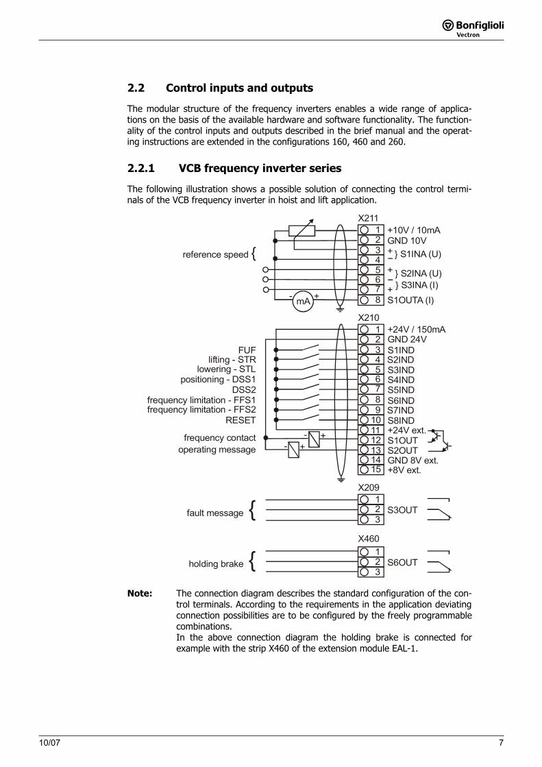
2.2.1 VCB frequency inverter series
The following illustration shows a possible solution of connecting the control termi-nals of the VCB frequency inverter in hoist and lift application.
+10V / 10mA12345678
GND 10V+
+
+
} S1INA (U)
} S2INA (U)} S3INA (I)
S1OUTA (I)
X211
9101112131415
S7INDS8IND+24V ext.S1OUTS2OUTGND 8V ext.+8V ext.
12345678
X210+24V / 150mAGND 24VS1INDS2INDS3INDS4INDS5INDS6IND
123
X209
S6OUT
mA +-
+-+-
fault message {
frequency contactoperating message
FUFlifting - STR
lowering - STLpositioning - DSS1
DSS2frequency limitation - FFS1frequency limitation - FFS2
RESET
reference speed {
X460
holding brake {
123
S3OUT
Note: The connection diagram describes the standard configuration of the con-trol terminals. According to the requirements in the application deviating connection possibilities are to be configured by the freely programmable combinations. In the above connection diagram the holding brake is connected for example with the strip X460 of the extension module EAL-1.
10/078
8 10/07
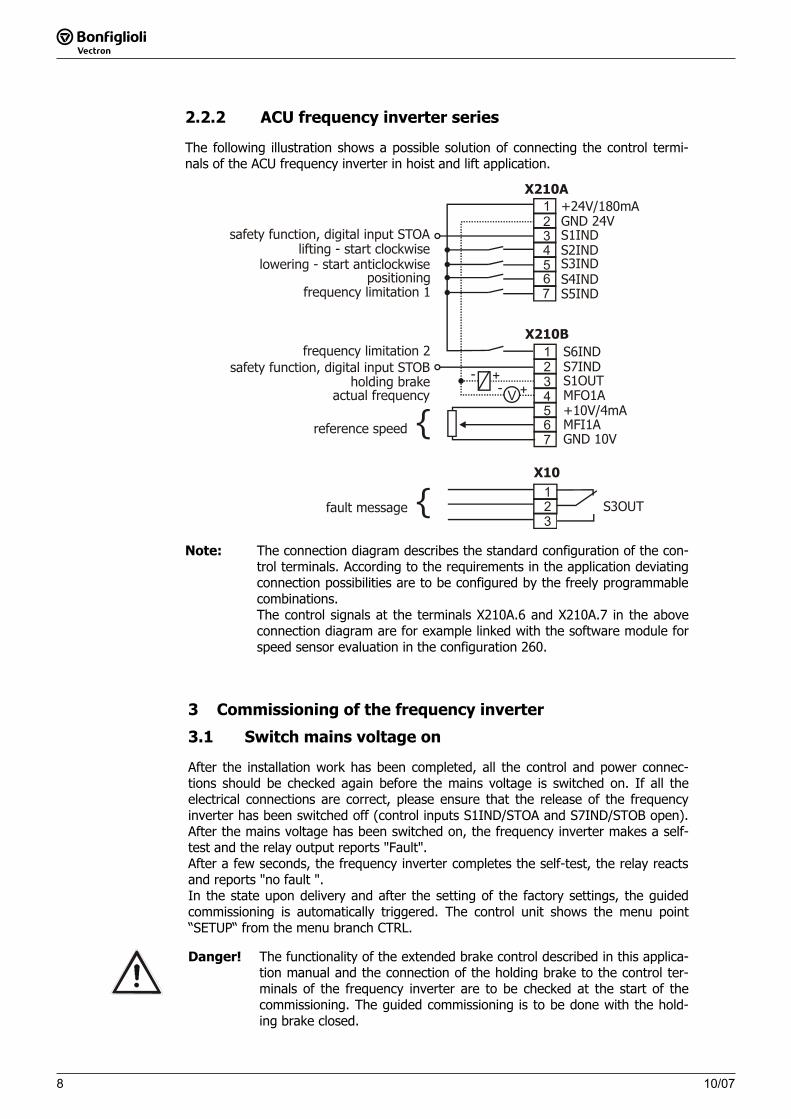
2.2.2 ACU frequency inverter series
The following illustration shows a possible solution of connecting the control termi-nals of the ACU frequency inverter in hoist and lift application.
S1OUTMFO1A+10V/4mA MFI1AGND 10V
1234567
X210A+24V/180mAGND 24VS1INDS2INDS3INDS4INDS5IND
S6INDX210B
1234567
V+
+--
safety function, digital input STOA
safety function, digital input STOB
lifting - start clockwiselowering - start anticlockwise
positioningfrequency limitation 1
frequency limitation 2
holding brakeactual frequency
123
S3OUT
X10
fault message {
reference speed {
S7IND
Note: The connection diagram describes the standard configuration of the con-trol terminals. According to the requirements in the application deviating connection possibilities are to be configured by the freely programmable combinations. The control signals at the terminals X210A.6 and X210A.7 in the above connection diagram are for example linked with the software module for speed sensor evaluation in the configuration 260.
3 Commissioning of the frequency inverter
3.1 Switch mains voltage on
After the installation work has been completed, all the control and power connec-tions should be checked again before the mains voltage is switched on. If all the electrical connections are correct, please ensure that the release of the frequency inverter has been switched off (control inputs S1IND/STOA and S7IND/STOB open). After the mains voltage has been switched on, the frequency inverter makes a self-test and the relay output reports "Fault". After a few seconds, the frequency inverter completes the self-test, the relay reacts and reports "no fault ". In the state upon delivery and after the setting of the factory settings, the guided commissioning is automatically triggered. The control unit shows the menu point “SETUP“ from the menu branch CTRL.
Danger! The functionality of the extended brake control described in this applica-tion manual and the connection of the holding brake to the control ter-minals of the frequency inverter are to be checked at the start of the commissioning. The guided commissioning is to be done with the hold-ing brake closed.
910/07
10/07 9
3.2 Setup with the control unit
The guided commissioning of the frequency inverter is described in the operating instructions among others for the configurations 110, 210 and 410. According to the operating instructions, the guided commissioning is to be done observing the safety information and further directives to be observed.
Attention! The guided commissioning contains the function for parameter identifi-cation. The parameters are determined and set accordingly by a meas-urement. Before the start of the measurement, the motor should not have been operated, as a part of the machine data is dependent upon the operating temperature.
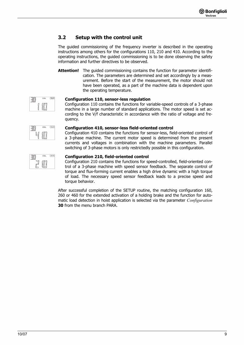
Configuration 110, sensor-less regulation Configuration 110 contains the functions for variable-speed controls of a 3-phase machine in a large number of standard applications. The motor speed is set ac-cording to the V/f characteristic in accordance with the ratio of voltage and fre-quency.
Configuration 410, sensor-less field-oriented control Configuration 410 contains the functions for sensor-less, field-oriented control of a 3-phase machine. The current motor speed is determined from the present currents and voltages in combination with the machine parameters. Parallel switching of 3-phase motors is only restrictedly possible in this configuration.
Configuration 210, field-oriented control Configuration 210 contains the functions for speed-controlled, field-oriented con-trol of a 3-phase machine with speed sensor feedback. The separate control of torque and flux-forming current enables a high drive dynamic with a high torque of load. The necessary speed sensor feedback leads to a precise speed and torque behavior.
After successful completion of the SETUP routine, the matching configuration 160, 260 or 460 for the extended activation of a holding brake and the function for auto-matic load detection in hoist application is selected via the parameter Configuration30 from the menu branch PARA.
10/0710
10 10/07
4 Activation of a holding brake
In some applications, for example hoist application, elevators or for some machine tools, activation of a holding brake demands an extended functionality for wear-free control of the brake. In addition, some applications demand, according to directives, that the motor is electrically separated from the frequency inverter by a safety contactor at a stand-still. These function modules of the software are activated by the configurations 160, 260 or 460 and supplement the control functions of configurations 110, 210, 410. The order of events during the start or stop process can be set with the help of the parameters described in the following chapters.
!Danger! If a dysfunction of the brake control can lead to major damage, in
particular damage to persons, a second independent device for closing the brake must exist. It cannot be ruled out that, for example by dam-age to the frequency inverter, the brake is released although the fre-quency inverter has been switched off.
4.1 Control inputs and outputs
The modular structure of the frequency inverters enables a broad spectrum of appli-cations on the basis of the available hardware and software functionality. The func-tionality of the control inputs and outputs described in the brief instructions and operating instructions is extended in configurations 160, 260 and 460.
4.1.1 Digital outputs
The function "Brake open" in the operating modes 40 and 140 of the digital outputs enables activation of a corresponding unit via the digital control outputs. The func-tion uses not only the control commands via the contact inputs but also the set starting and stopping behavior to control the parameterized digital output. These operating modes of the digital outputs are replaced by the Operation mode 41 for the extended brake control in configurations 160, 260 and 460. The function for the activation of the safety switch is to be assigned to one of the digital control outputs with Operation mode 42.
Operation mode Function
41 - Brake open The digital output becomes active (an open con-tact closes) when the brake is released.
42 - Safety contactor The digital output becomes active when the fre-quency inverter is connected to the motor (safety contactor on).
Attention! For safety reasons, the inverted Operation mode 141 is not avail-able. In this operation mode, the brake is not released with the digital output active. For example, this would also be the case with a voltage-free frequency inverter or during the initialization phase.
1110/07
10/07 11
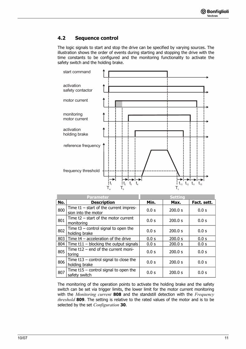
4.2 Sequence control
The logic signals to start and stop the drive can be specified by varying sources. The illustration shows the order of events during starting and stopping the drive with the time constants to be configured and the monitoring functionality to activate the safety switch and the holding brake.
Ta Tb Tc
t2t1 t3 t13 t11 t15t4
start command
activationsafety contactor
activationholding brake
motor current
monitoringmotor current
reference frequency
frequency threshold
t12
Parameter SettingNo. Description Min. Max. Fact. sett.
800 Time t1 – start of the current impres-sion into the motor
0.0 s 200.0 s 0.0 s
801 Time t2 – start of the motor current monitoring
0.0 s 200.0 s 0.0 s
802 Time t3 – control signal to open the holding brake
0.0 s 200.0 s 0.0 s
803 Time t4 – acceleration of the drive 0.0 s 200.0 s 0.0 s 804 Time t11 – blocking the output signals 0.0 s 200.0 s 0.0 s
805 Time t12 – end of the current moni-toring
0.0 s 200.0 s 0.0 s
806 Time t13 – control signal to close the holding brake
0.0 s 200.0 s 0.0 s
807 Time t15 – control signal to open the safety switch
0.0 s 200.0 s 0.0 s
The monitoring of the operation points to activate the holding brake and the safety switch can be set via trigger limits, the lower limit for the motor current monitoring with the Monitoring current 808 and the standstill detection with the Frequencythreshold 809. The setting is relative to the rated values of the motor and is to be selected by the set Configuration 30.
10/071212 10/07
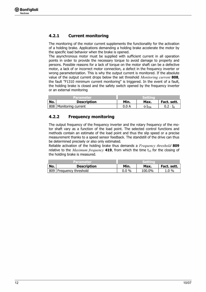
4.2.1 Current monitoring
The monitoring of the motor current supplements the functionality for the activation of a holding brake. Applications demanding a holding brake accelerate the motor by the specific load behavior when the brake is opened. The asynchronous motor must be supplied with sufficient current in all operation points in order to provide the necessary torque to avoid damage to property and persons. Possible reasons for a lack of torque on the motor shaft can be a defective motor, a lack of or incorrect motor connection, a defect in the frequency inverter or wrong parameterization. This is why the output current is monitored. If the absolute value of the output current drops below the set threshold Monitoring current 808,the fault "F1310 minimum current monitoring" is triggered. In the event of a fault, the holding brake is closed and the safety switch opened by the frequency inverter or an external monitoring
Parameter SettingNo. Description Min. Max. Fact. sett. 808 Monitoring current 0.0 A o⋅IFIN 0.2 ⋅ IR
4.2.2 Frequency monitoring
The output frequency of the frequency inverter and the rotary frequency of the mo-tor shaft vary as a function of the load point. The selected control functions and methods contain an estimate of the load point and thus the slip speed or a precise measurement thanks to a speed sensor feedback. The standstill of the drive can thus be determined precisely or also only estimated. Reliable activation of the holding brake thus demands a Frequency threshold 809relative to the Maximum frequency 419, from which the time t13 for the closing of the holding brake is measured.
Parameter SettingNo. Description Min. Max. Fact. sett.
809 Frequency threshold 0.0 % 100.0% 1.0 %
1310/0710/07 13
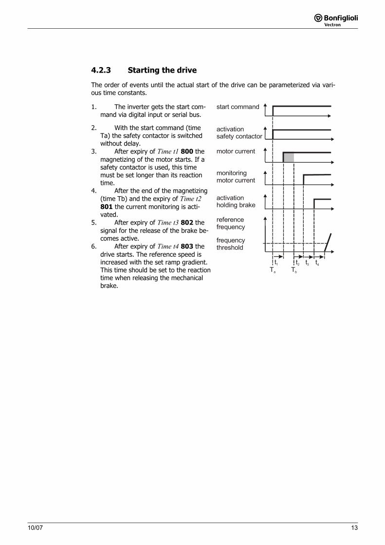
4.2.3 Starting the drive
The order of events until the actual start of the drive can be parameterized via vari-ous time constants.
1. The inverter gets the start com-mand via digital input or serial bus.
2. With the start command (time Ta) the safety contactor is switched without delay.
3. After expiry of Time t1 800 the magnetizing of the motor starts. If a safety contactor is used, this time must be set longer than its reaction time.
4. After the end of the magnetizing (time Tb) and the expiry of Time t2801 the current monitoring is acti-vated.
5. After expiry of Time t3 802 the signal for the release of the brake be-comes active.
6. After expiry of Time t4 803 the drive starts. The reference speed is increased with the set ramp gradient. This time should be set to the reaction time when releasing the mechanical brake.
Ta Tb
t2t1 t3 t4
start command
activationsafety contactor
activationholding brake
motor current
monitoringmotor current
referencefrequency
frequencythreshold
10/071414 10/07
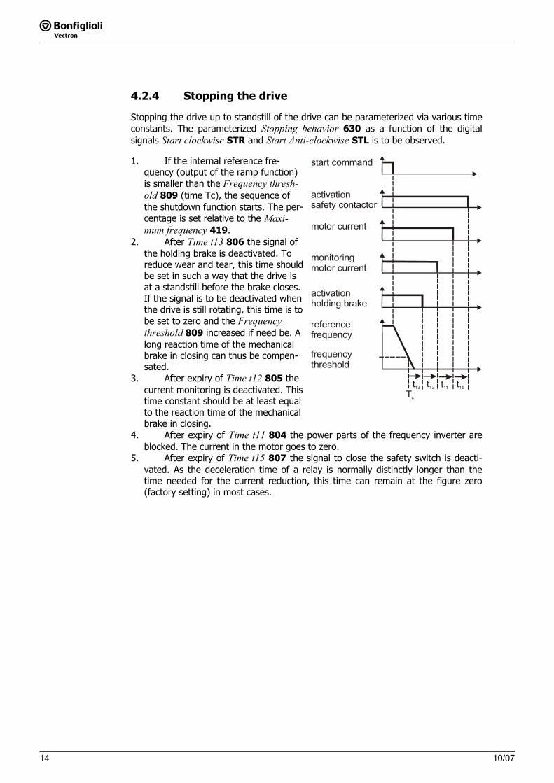
4.2.4 Stopping the drive
Stopping the drive up to standstill of the drive can be parameterized via various time constants. The parameterized Stopping behavior 630 as a function of the digital signals Start clockwise STR and Start Anti-clockwise STL is to be observed.
1. If the internal reference fre-quency (output of the ramp function) is smaller than the Frequency thresh-old 809 (time Tc), the sequence of the shutdown function starts. The per-centage is set relative to the Maxi-mum frequency 419.
2. After Time t13 806 the signal of the holding brake is deactivated. To reduce wear and tear, this time should be set in such a way that the drive is at a standstill before the brake closes.If the signal is to be deactivated when the drive is still rotating, this time is to be set to zero and the Frequencythreshold 809 increased if need be. A long reaction time of the mechanical brake in closing can thus be compen-sated.
3. After expiry of Time t12 805 the current monitoring is deactivated. This time constant should be at least equal to the reaction time of the mechanical brake in closing.
t13 t11 t15t12
Tc
start command
activationsafety contactor
activationholding brake
motor current
monitoringmotor current
referencefrequency
frequencythreshold
4. After expiry of Time t11 804 the power parts of the frequency inverter are blocked. The current in the motor goes to zero.
5. After expiry of Time t15 807 the signal to close the safety switch is deacti-vated. As the deceleration time of a relay is normally distinctly longer than the time needed for the current reduction, this time can remain at the figure zero (factory setting) in most cases.
1510/0710/07 15
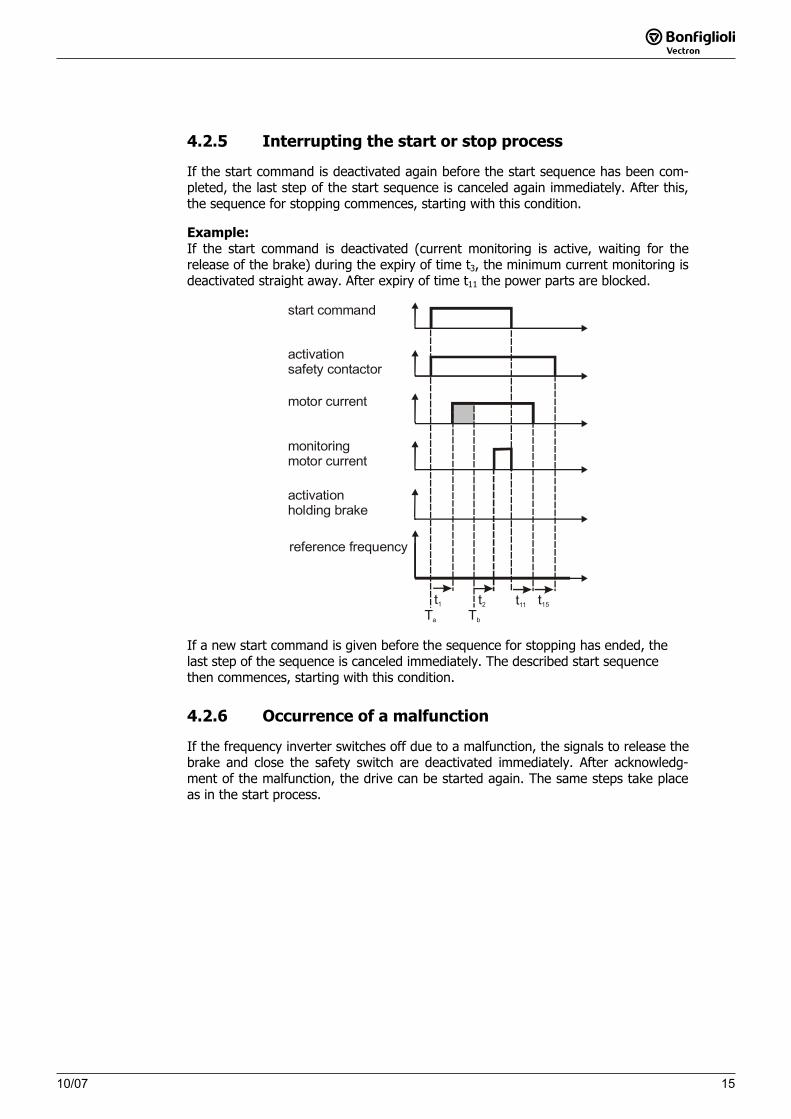
4.2.5 Interrupting the start or stop process
If the start command is deactivated again before the start sequence has been com-pleted, the last step of the start sequence is canceled again immediately. After this, the sequence for stopping commences, starting with this condition.
Example:If the start command is deactivated (current monitoring is active, waiting for the release of the brake) during the expiry of time t3, the minimum current monitoring is deactivated straight away. After expiry of time t11 the power parts are blocked.
Ta Tb
t2t1 t11 t15
start command
activationsafety contactor
activationholding brake
motor current
monitoringmotor current
reference frequency
If a new start command is given before the sequence for stopping has ended, the last step of the sequence is canceled immediately. The described start sequence then commences, starting with this condition.
4.2.6 Occurrence of a malfunction
If the frequency inverter switches off due to a malfunction, the signals to release the brake and close the safety switch are deactivated immediately. After acknowledg-ment of the malfunction, the drive can be started again. The same steps take place as in the start process.
10/071616 10/07
5 Load detection for hoist application and luffing jib cranes
The present documentation supplements the operating instructions for applications with an extended activation of a holding brake and the function for automatic load detection in hoist application and luffing jib cranes. The application manual documents the additional functionality of the frequency in-verters in the software configurations 160, 260 and 460. These configurations sup-plement the configurations 110, 210 and 410, which are described in detail in the operating instructions.
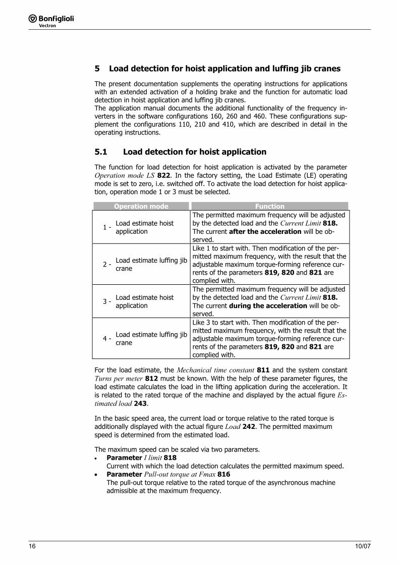
5.1 Load detection for hoist application
The function for load detection for hoist application is activated by the parameter Operation mode LS 822. In the factory setting, the Load Estimate (LE) operating mode is set to zero, i.e. switched off. To activate the load detection for hoist applica-tion, operation mode 1 or 3 must be selected.
Operation mode Function
1 - Load estimate hoist application
The permitted maximum frequency will be adjusted by the detected load and the Current Limit 818.The current after the acceleration will be ob-served.
2 - Load estimate luffing jib crane
Like 1 to start with. Then modification of the per-mitted maximum frequency, with the result that the adjustable maximum torque-forming reference cur-rents of the parameters 819, 820 and 821 are complied with.
3 - Load estimate hoist application
The permitted maximum frequency will be adjusted by the detected load and the Current Limit 818.The current during the acceleration will be ob-served.
4 - Load estimate luffing jib crane
Like 3 to start with. Then modification of the per-mitted maximum frequency, with the result that the adjustable maximum torque-forming reference cur-rents of the parameters 819, 820 and 821 are complied with.
For the load estimate, the Mechanical time constant 811 and the system constant Turns per meter 812 must be known. With the help of these parameter figures, the load estimate calculates the load in the lifting application during the acceleration. It is related to the rated torque of the machine and displayed by the actual figure Es-timated load 243.
In the basic speed area, the current load or torque relative to the rated torque is additionally displayed with the actual figure Load 242. The permitted maximum speed is determined from the estimated load.
The maximum speed can be scaled via two parameters. • Parameter I limit 818
Current with which the load detection calculates the permitted maximum speed.• Parameter Pull-out torque at Fmax 816
The pull-out torque relative to the rated torque of the asynchronous machine admissible at the maximum frequency.
1710/0710/07 17
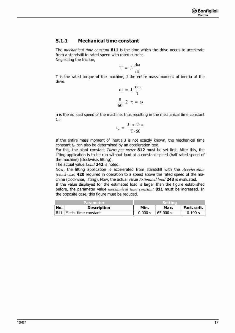
5.1.1 Mechanical time constant
The mechanical time constant 811 is the time which the drive needs to accelerate from a standstill to rated speed with rated current.
Neglecting the friction,
dtdωJT ⋅=
T is the rated torque of the machine, J the entire mass moment of inertia of the drive.
TdωJdt ⋅=
ωπ260n
=⋅⋅
n is the no load speed of the machine, thus resulting in the mechanical time constant tm:
60Tπ2nJtm ⋅⋅⋅⋅
=
If the entire mass moment of inertia J is not exactly known, the mechanical time constant tm can also be determined by an acceleration test. For this, the plant constant Turns per meter 812 must be set first. After this, the lifting application is to be run without load at a constant speed (half rated speed of the machine) (clockwise, lifting). The actual value Load 242 is noted. Now, the lifting application is accelerated from standstill with the Acceleration (clockwise) 420 required in operation to a speed above the rated speed of the ma-chine (clockwise, lifting). Now, the actual value Estimated load 243 is evaluated. If the value displayed for the estimated load is larger than the figure established before, the parameter value mechanical time constant 811 must be increased. In the opposite case, this figure must be reduced.
Parameter SettingNo. Description Min. Max. Fact. sett.
811 Mech. time constant 0.000 s 65.000 s 0.190 s
10/0718
18 10/07
5.1.2 Turns per meter
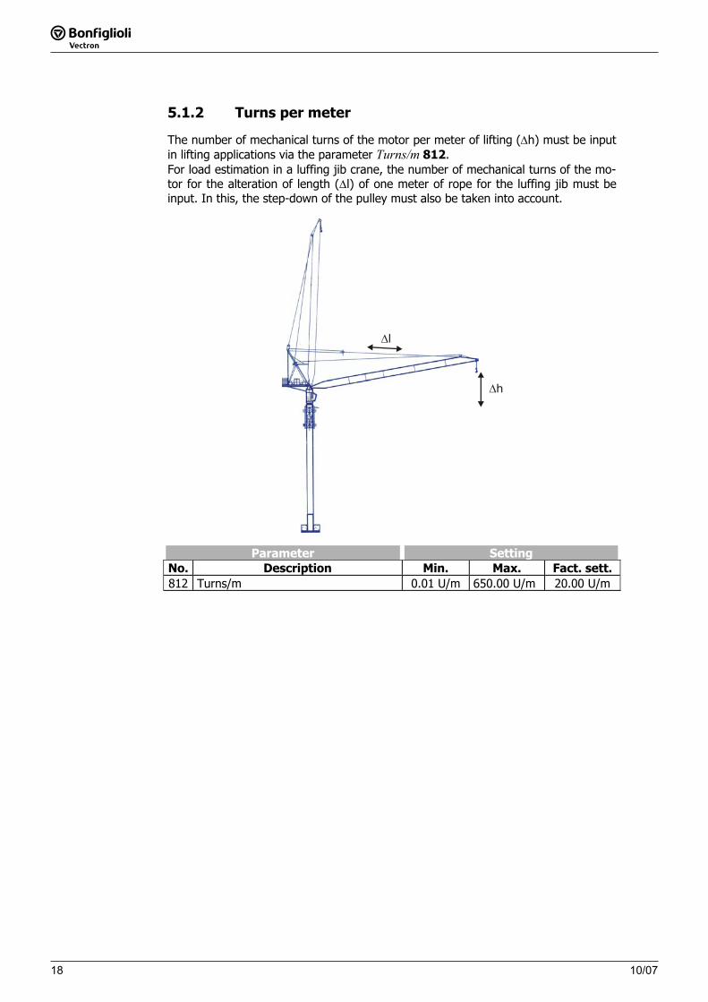
The number of mechanical turns of the motor per meter of lifting (Δh) must be input in lifting applications via the parameter Turns/m 812.
For load estimation in a luffing jib crane, the number of mechanical turns of the mo-tor for the alteration of length (Δl) of one meter of rope for the luffing jib must be input. In this, the step-down of the pulley must also be taken into account.
Δl
Δh
Parameter SettingNo. Description Min. Max. Fact. sett.
812 Turns/m 0.01 U/m 650.00 U/m 20.00 U/m
1910/07
10/07 19
5.1.3 Load estimate
The load estimate is done in the basic speed area. In order to avoid faults at a stand-still and very low speeds, the load estimate is only done above a rotary frequency limit, which can be set with the parameter Fm lower value LE 813. The value is input in per cent and is relative to the rated frequency of the machine.
Parameter SettingNo. Description Min. Max. Fact. sett.
813 Fm lower value LE 0 % 100 % 10 %
The load estimate starts above the rotary frequency given by the parameter Fmlower value LS 813. The maximum time of the load estimate can be set with the parameter Max Time LE 815. If the set time has been exceeded of if the basic speed area is left, the determined Load 243 is displayed. From it, the maximum admissible speed is calculated.
Parameter SettingNo. Description Min. Max. Fact. sett.
815 Max time LE 0.001 s 65.000 s 2.000 s
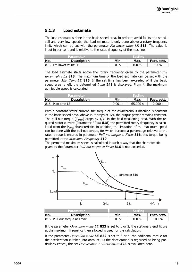
With a constant stator current, the torque of the asynchronous machine is constant in the basic speed area. Above it, it drops at 1/x, the output power remains constant. The pull-out torque (Tbreak) drops by 1/x² in the field-weakening area. With the re-quired stator current (Parameter I limit 818) the permitted rotary frequency is calcu-lated from the Pconst characteristic. In addition, the limitation of the maximum speed can be done with the pull-out torque, for which purpose a percentage relative to the rated torque is entered in parameter Pull-out torque at Fmax 816, this torque being permitted at the Maximum Frequency 419.The permitted maximum speed is calculated in such a way that the characteristic given by the Parameter Pull-out torque at Fmax 816 is not exceeded.
T
ffR 2 fR 3 fR 4 fR
Tconst
Pconst
Tbreak
parameter 816
fR
TR
Load
Parameter SettingNo. Description Min. Max. Fact. sett.
816 Pull-out torque at Fmax 0 % 100 % 100 %
If the parameter Operation mode LE 822 is set to 1 or 2, the stationary end figure at the maximum frequency then allowed is used for the calculation.
If the parameter Operation mode LE 822 is set to 3 or 4, the additional torque for the acceleration is taken into account. As the deceleration is regarded as being par-ticularly critical, the set Deceleration Anti-clockwise 423 is evaluated here.
10/0720
20 10/07
5.1.4 Speed switch-off limit
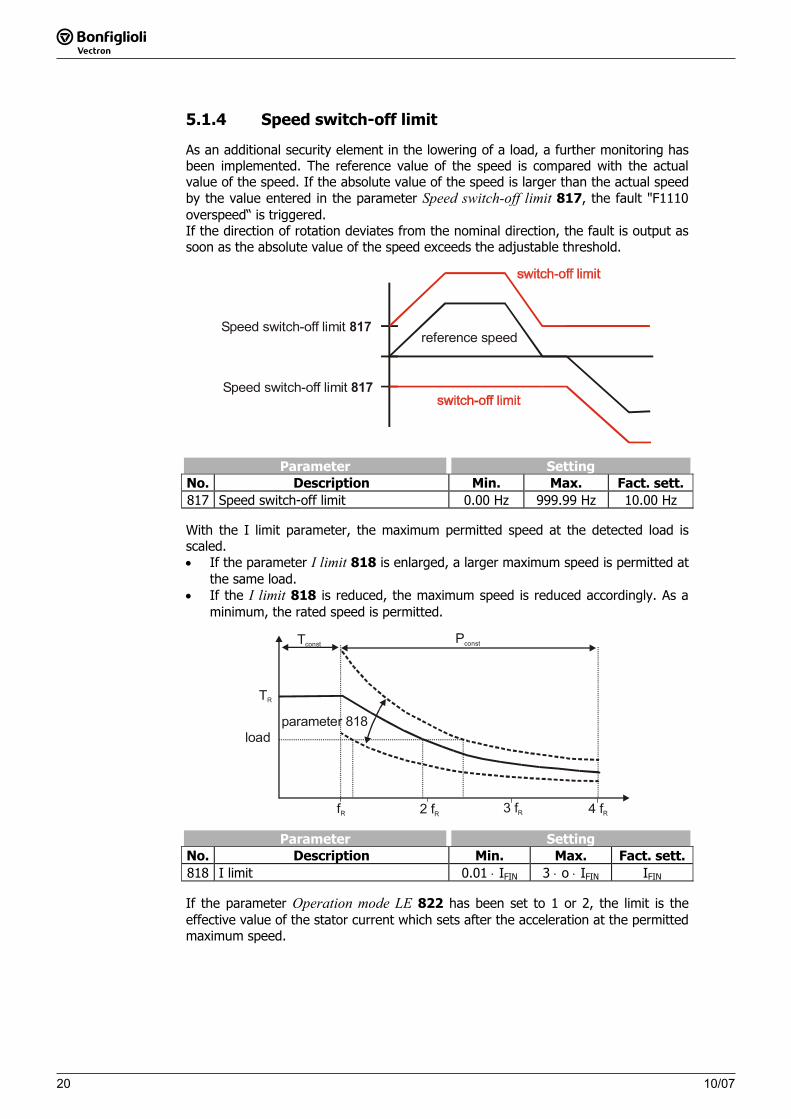
As an additional security element in the lowering of a load, a further monitoring has been implemented. The reference value of the speed is compared with the actual value of the speed. If the absolute value of the speed is larger than the actual speed by the value entered in the parameter Speed switch-off limit 817, the fault "F1110 overspeed“ is triggered. If the direction of rotation deviates from the nominal direction, the fault is output as soon as the absolute value of the speed exceeds the adjustable threshold.
reference speedSpeed switch-off limit 817
Speed switch-off limit 817
Parameter SettingNo. Description Min. Max. Fact. sett.
817 Speed switch-off limit 0.00 Hz 999.99 Hz 10.00 Hz
With the I limit parameter, the maximum permitted speed at the detected load is scaled. • If the parameter I limit 818 is enlarged, a larger maximum speed is permitted at
the same load. • If the I limit 818 is reduced, the maximum speed is reduced accordingly. As a
minimum, the rated speed is permitted.
fR 2 fR 3 fR 4 fR
Tconst Pconst
TR
parameter 818load
Parameter SettingNo. Description Min. Max. Fact. sett.818 I limit 0.01 ⋅ IFIN 3 ⋅ o ⋅ IFIN IFIN
If the parameter Operation mode LE 822 has been set to 1 or 2, the limit is the effective value of the stator current which sets after the acceleration at the permitted maximum speed.
10/07 21
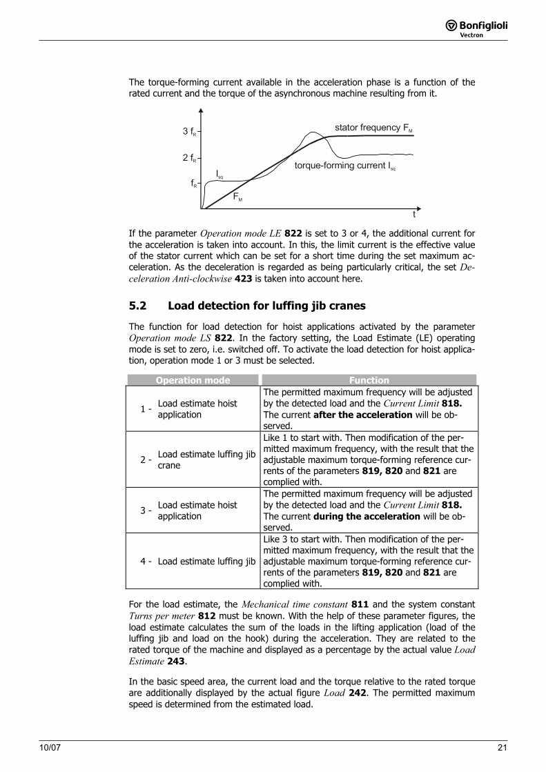
The torque-forming current available in the acceleration phase is a function of the rated current and the torque of the asynchronous machine resulting from it.
t
fR
3 fR
FM
Isq
stator frequency FM
2 fR torque-forming current Isq
If the parameter Operation mode LE 822 is set to 3 or 4, the additional current for the acceleration is taken into account. In this, the limit current is the effective value of the stator current which can be set for a short time during the set maximum ac-celeration. As the deceleration is regarded as being particularly critical, the set De-celeration Anti-clockwise 423 is taken into account here.
5.2 Load detection for luffing jib cranes
The function for load detection for hoist applications activated by the parameter Operation mode LS 822. In the factory setting, the Load Estimate (LE) operating mode is set to zero, i.e. switched off. To activate the load detection for hoist applica-tion, operation mode 1 or 3 must be selected.
Operation mode Function
1 - Load estimate hoist application
The permitted maximum frequency will be adjusted by the detected load and the Current Limit 818.The current after the acceleration will be ob-served.
2 - Load estimate luffing jib crane
Like 1 to start with. Then modification of the per-mitted maximum frequency, with the result that the adjustable maximum torque-forming reference cur-rents of the parameters 819, 820 and 821 are complied with.
3 - Load estimate hoist application
The permitted maximum frequency will be adjusted by the detected load and the Current Limit 818.The current during the acceleration will be ob-served.
4 - Load estimate luffing jib
Like 3 to start with. Then modification of the per-mitted maximum frequency, with the result that the adjustable maximum torque-forming reference cur-rents of the parameters 819, 820 and 821 are complied with.
For the load estimate, the Mechanical time constant 811 and the system constant Turns per meter 812 must be known. With the help of these parameter figures, the load estimate calculates the sum of the loads in the lifting application (load of the luffing jib and load on the hook) during the acceleration. They are related to the rated torque of the machine and displayed as a percentage by the actual value LoadEstimate 243.
In the basic speed area, the current load and the torque relative to the rated torque are additionally displayed by the actual figure Load 242. The permitted maximum speed is determined from the estimated load.
2110/07
10/07 21
The torque-forming current available in the acceleration phase is a function of the rated current and the torque of the asynchronous machine resulting from it.
t
fR
3 fR
FM
Isq
stator frequency FM
2 fR torque-forming current Isq
If the parameter Operation mode LE 822 is set to 3 or 4, the additional current for the acceleration is taken into account. In this, the limit current is the effective value of the stator current which can be set for a short time during the set maximum ac-celeration. As the deceleration is regarded as being particularly critical, the set De-celeration Anti-clockwise 423 is taken into account here.
5.2 Load detection for luffing jib cranes
The function for load detection for hoist applications activated by the parameter Operation mode LS 822. In the factory setting, the Load Estimate (LE) operating mode is set to zero, i.e. switched off. To activate the load detection for hoist applica-tion, operation mode 1 or 3 must be selected.
Operation mode Function
1 - Load estimate hoist application
The permitted maximum frequency will be adjusted by the detected load and the Current Limit 818.The current after the acceleration will be ob-served.
2 - Load estimate luffing jib crane
Like 1 to start with. Then modification of the per-mitted maximum frequency, with the result that the adjustable maximum torque-forming reference cur-rents of the parameters 819, 820 and 821 are complied with.
3 - Load estimate hoist application
The permitted maximum frequency will be adjusted by the detected load and the Current Limit 818.The current during the acceleration will be ob-served.
4 - Load estimate luffing jib
Like 3 to start with. Then modification of the per-mitted maximum frequency, with the result that the adjustable maximum torque-forming reference cur-rents of the parameters 819, 820 and 821 are complied with.
For the load estimate, the Mechanical time constant 811 and the system constant Turns per meter 812 must be known. With the help of these parameter figures, the load estimate calculates the sum of the loads in the lifting application (load of the luffing jib and load on the hook) during the acceleration. They are related to the rated torque of the machine and displayed as a percentage by the actual value LoadEstimate 243.
In the basic speed area, the current load and the torque relative to the rated torque are additionally displayed by the actual figure Load 242. The permitted maximum speed is determined from the estimated load.
10/072222 10/07
The maximum speed can be scaled via two parameters. • Parameter I limit 818
Current with which the load detection calculates the permitted maximum speed.• Parameter Pull-out torque at Fmax 816
The pull-out torque relative to the rated torque of the asynchronous machine admissible at the maximum frequency.
After this, the permitted maximum speed is modified as a function of the position of the luffing jib.
The parameters Mech. time constant 811, Turns/m 812, Fm lower value LE 813,Max time LE 815, Pull-out torque at Fmax 816, Speed switch-off limit 817 and Ilimit 818 are parameterized in a way comparable with the described settings for the load detection for the lifting crane.
In a crane with a luffing jib, the torque acting on the motor changes with the angle of the luffing jib. In order not to overload the motor in the field weakening area, the maximum permitted speed of the motor must therefore be adapted as a function of the angle of the luffing jib. These settings for the luffing jib are to be done via the parameters described below: Desired Isq up 819, Desired Isq down at FsR 820 and Desired Isq down at Fmax821.
2310/07
10/07 23
5.2.1 Torque-forming current Isq
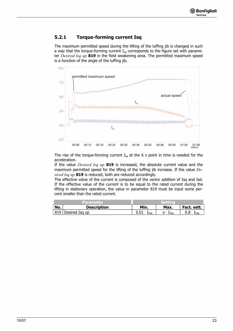
The maximum permitted speed during the lifting of the luffing jib is changed in such a way that the torque-forming current Isq corresponds to the figure set with parame-ter Desired Isq up 819 in the field weakening area. The permitted maximum speed is a function of the angle of the luffing jib.
min:s00:06 00:12 00:18 00:24 00:30 00:36 00:42 00:48 00:54 01:00 01:06
10,0
7,5
5,0
2,5
0,0
-2,5
Isq
Isd
permitted maximum speed
actual speed
The rise of the torque-forming current Isq at the 6 s point in time is needed for the acceleration. If the value Desired Isq up 819 is increased, the absolute current value and the maximum permitted speed for the lifting of the luffing jib increase. If the value De-sired Isq up 819 is reduced, both are reduced accordingly. The effective value of the current is composed of the vector addition of Isq and Isd. If the effective value of the current is to be equal to the rated current during the lifting in stationary operation, the value in parameter 819 must be input some per-cent smaller than the rated current.
Parameter SettingNo. Description Min. Max. Fact. sett.819 Desired Isq up 0.01 ⋅ IFIN o ⋅ IFIN 0.8 ⋅ IFIN
10/072424 10/07
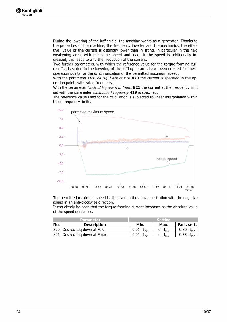
During the lowering of the luffing jib, the machine works as a generator. Thanks to the properties of the machine, the frequency inverter and the mechanics, the effec-tive value of the current is distinctly lower than in lifting, in particular in the field weakening area, with the same speed and load. If the speed is additionally in-creased, this leads to a further reduction of the current. Two further parameters, with which the reference value for the torque-forming cur-rent Isq is stated in the lowering of the luffing jib arm, have been created for these operation points for the synchronization of the permitted maximum speed. With the parameter Desired Isq down at FsR 820 the current is specified in the op-eration points with rated frequency. With the parameter Desired Isq down at Fmax 821 the current at the frequency limit set with the parameter Maximum Frequency 419 is specified. The reference value used for the calculation is subjected to linear interpolation within these frequency limits.
min:s00:30 00:36 00:42 00:48 00:54 01:00 01:06 01:12 01:18 01:24 01:30
10,0
7,5
5,0
2,5
0,0
-2,5
-5,0
-7,5
-10,0
permitted maximum speed
actual speed
Isq
Isd
The permitted maximum speed is displayed in the above illustration with the negative speed in an anti-clockwise direction. It can clearly be seen that the torque-forming current increases as the absolute value of the speed decreases.
Parameter SettingNo. Description Min. Max. Fact. sett.820 Desired Isq down at FsR 0.01 ⋅ IFIN o ⋅ IFIN 0.80 ⋅ IFIN
821 Desired Isq down at Fmax 0.01 ⋅ IFIN o ⋅ IFIN 0.55 ⋅ IFIN
2510/0710/07 25
5.3 Limitation of the speed by fixed frequencies
The maximum permitted speed can be limited by the parameters Fixed Frequency 1480, Fixed Frequency 2 481 , Fixed Frequency 3 482 and Fixed Frequency 3 483.For this, the parameter Frequency upper limit source 769 is to be set to the opera-tion mode 110. If the additional limitation has been activated, the maximum frequency (maybe per-mitted by the load detection or its modification during the movement of a luffing jib) is limited to the current fixed frequency. The limitation is effective for both clockwise and anti-clockwise.
Operation mode Function 0 - Off There is no additional speed limitation
110 - Fixed limit The selected fixed frequencies are taken into account for limitation
5.4 Temperature adjustment
The properties of the asynchronous machine change with the temperature and can be taken into account via a suitable measurement or estimate. Various methods and sources of actual values for temperature detection are to be selected via the pa-rameter Operation mode Temperature adjustment 465.The parameter Operation mode Temperature adjustment 465 is pre-set to the op-eration mode 4-temperature estimate in the configurations 260 and 460. In switch-ing on, the temperature of the asynchronous machine is estimated and taken into account for correct calculation. If this is not required, the parameter Operation mode Temperature adjustment 465must be parameterized to the operation mode 0-Off.
Operation mode Function 0 - Off The function is deactivated
1 - Temp. Detect. At AE1 Temperature synchronization (0 … 200°C => 0/2 … 10V),actual temperature value to multifunctional input 1
2 - Temp. Detect. At AE2 Temperature synchronization (0 … 200°C => 0/2 … 10V),actual temperature value to multifunctional input 2
3 - Temp. Detect. At AE3 Temperature synchronization (0 … 200°C => 0/2 … 10V),actual temperature value to multifunctional input 3
4 - Temperature estimate Temperature synchronization by estimation
11 to 13 Operation modes 1 to 3 with the VECTRON extension temperature synchronization (-26.0 … 207.8°C => 0 … 10V)
The Adjusting temperature 467 is to be set to the temperature at which the optimi-zation of the extended machine data has been carried out. The temperature can be read out via the actual value parameter Winding temperature 226 and can be used in the optimization for the parameter.
Parameter SettingNo. Description Min. Max. Fact. sett.
467 Adjusting temperature -50.0 °C 300.0 °C 100.0 °C
10/0726 26 10/07
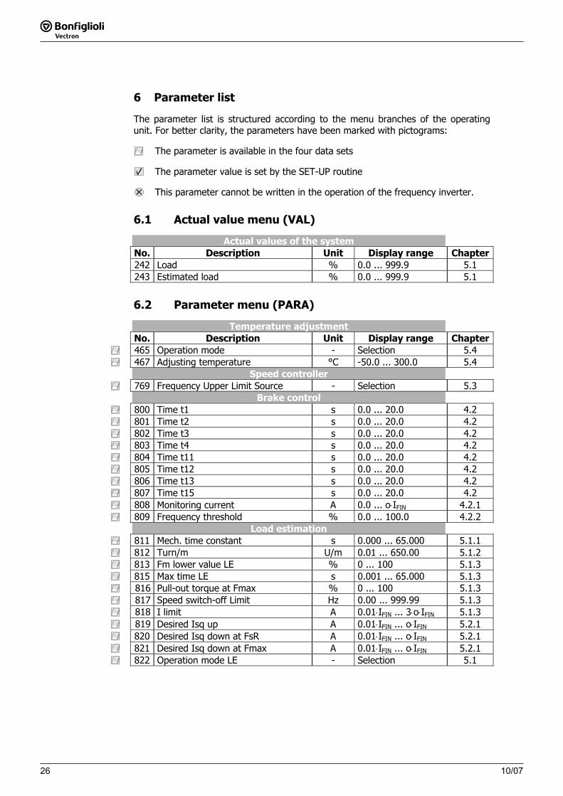
6 Parameter list
The parameter list is structured according to the menu branches of the operating unit. For better clarity, the parameters have been marked with pictograms:
The parameter is available in the four data sets
The parameter value is set by the SET-UP routine
This parameter cannot be written in the operation of the frequency inverter.
6.1 Actual value menu (VAL)
Actual values of the system No. Description Unit Display range Chapter
242 Load % 0.0 ... 999.9 5.1 243 Estimated load % 0.0 ... 999.9 5.1
6.2 Parameter menu (PARA)
Temperature adjustment No. Description Unit Display range Chapter465 Operation mode - Selection 5.4467 Adjusting temperature °C -50.0 ... 300.0 5.4
Speed controller 769 Frequency Upper Limit Source - Selection 5.3
Brake control 800 Time t1 s 0.0 ... 20.0 4.2801 Time t2 s 0.0 ... 20.0 4.2802 Time t3 s 0.0 ... 20.0 4.2803 Time t4 s 0.0 ... 20.0 4.2804 Time t11 s 0.0 ... 20.0 4.2805 Time t12 s 0.0 ... 20.0 4.2806 Time t13 s 0.0 ... 20.0 4.2807 Time t15 s 0.0 ... 20.0 4.2808 Monitoring current A 0.0 ... o⋅IFIN 4.2.1809 Frequency threshold % 0.0 ... 100.0 4.2.2
Load estimation 811 Mech. time constant s 0.000 ... 65.000 5.1.1812 Turn/m U/m 0.01 ... 650.00 5.1.2813 Fm lower value LE % 0 ... 100 5.1.3815 Max time LE s 0.001 ... 65.000 5.1.3816 Pull-out torque at Fmax % 0 ... 100 5.1.3817 Speed switch-off Limit Hz 0.00 ... 999.99 5.1.3818 I limit A 0.01⋅IFIN ... 3⋅o⋅IFIN 5.1.3819 Desired Isq up A 0.01⋅IFIN ... o⋅IFIN 5.2.1820 Desired Isq down at FsR A 0.01⋅IFIN ... o⋅IFIN 5.2.1821 Desired Isq down at Fmax A 0.01⋅IFIN ... o⋅IFIN 5.2.1822 Operation mode LE - Selection 5.1

26 10/07
6 Parameter list
The parameter list is structured according to the menu branches of the operating unit. For better clarity, the parameters have been marked with pictograms:
The parameter is available in the four data sets
The parameter value is set by the SET-UP routine
This parameter cannot be written in the operation of the frequency inverter.
6.1 Actual value menu (VAL)
Actual values of the system No. Description Unit Display range Chapter
242 Load % 0.0 ... 999.9 5.1 243 Estimated load % 0.0 ... 999.9 5.1
6.2 Parameter menu (PARA)
Temperature adjustment No. Description Unit Display range Chapter465 Operation mode - Selection 5.4467 Adjusting temperature °C -50.0 ... 300.0 5.4
Speed controller 769 Frequency Upper Limit Source - Selection 5.3
Brake control 800 Time t1 s 0.0 ... 20.0 4.2801 Time t2 s 0.0 ... 20.0 4.2802 Time t3 s 0.0 ... 20.0 4.2803 Time t4 s 0.0 ... 20.0 4.2804 Time t11 s 0.0 ... 20.0 4.2805 Time t12 s 0.0 ... 20.0 4.2806 Time t13 s 0.0 ... 20.0 4.2807 Time t15 s 0.0 ... 20.0 4.2808 Monitoring current A 0.0 ... o⋅IFIN 4.2.1809 Frequency threshold % 0.0 ... 100.0 4.2.2
Load estimation 811 Mech. time constant s 0.000 ... 65.000 5.1.1812 Turn/m U/m 0.01 ... 650.00 5.1.2813 Fm lower value LE % 0 ... 100 5.1.3815 Max time LE s 0.001 ... 65.000 5.1.3816 Pull-out torque at Fmax % 0 ... 100 5.1.3817 Speed switch-off Limit Hz 0.00 ... 999.99 5.1.3818 I limit A 0.01⋅IFIN ... 3⋅o⋅IFIN 5.1.3819 Desired Isq up A 0.01⋅IFIN ... o⋅IFIN 5.2.1820 Desired Isq down at FsR A 0.01⋅IFIN ... o⋅IFIN 5.2.1821 Desired Isq down at Fmax A 0.01⋅IFIN ... o⋅IFIN 5.2.1822 Operation mode LE - Selection 5.1


www.bonfiglioli.com
Bonfiglioli Riduttori S.p.A.Via Giovanni XXIII, 7/A40012 Lippo di Calderara di RenoBologna, Italy
tel: +39 051 647 3111fax: +39 051 647 [email protected]
VEC 557 R0
ACTIVE CUBEApplication manual - Crane drivesBrake control and load detectionConfigurations 160, 260 and 460
Bonfiglioli has been designing and developing innovative and reliable power transmission and control solutions for industry, mobile machinery and renewable energy applications since 1956.