Embed Size (px)
Citation preview
A/CServiceCenterVAS 581 001
Air conditioning service unitOperating manual

EN 3
VAS 581 001
Contents1 About this operating manual. . . . . . . . . . . . . . . . . . . . . . . . . . . .51.1 Hotline . . . . . . . . . . . . . . . . . . . . . . . . . . . . . . . . . . . . . . . . . . . . . . . . . . . 5
1.2 Explanation of symbols in this operating manual. . . . . . . . . . . . . . . . . . . 6
2 Safety. . . . . . . . . . . . . . . . . . . . . . . . . . . . . . . . . . . . . . . . . . . . . . .72.1 General safety instructions . . . . . . . . . . . . . . . . . . . . . . . . . . . . . . . . . . . 7
2.2 Operating the unit safely . . . . . . . . . . . . . . . . . . . . . . . . . . . . . . . . . . . . . 8
2.3 Handling refrigerant safely. . . . . . . . . . . . . . . . . . . . . . . . . . . . . . . . . . . . 9
2.4 Operational measures when using the unit . . . . . . . . . . . . . . . . . . . . . . 10
2.5 Warnings on the A/CServiceCenter . . . . . . . . . . . . . . . . . . . . . . . . . . . 11
2.6 Safety devices . . . . . . . . . . . . . . . . . . . . . . . . . . . . . . . . . . . . . . . . . . . . 11
3 Scope of delivery . . . . . . . . . . . . . . . . . . . . . . . . . . . . . . . . . . . .12
4 Accessories . . . . . . . . . . . . . . . . . . . . . . . . . . . . . . . . . . . . . . . .12
5 Proper use. . . . . . . . . . . . . . . . . . . . . . . . . . . . . . . . . . . . . . . . . .13
6 Overview of the A/CServiceCenter. . . . . . . . . . . . . . . . . . . . . .146.1 Front . . . . . . . . . . . . . . . . . . . . . . . . . . . . . . . . . . . . . . . . . . . . . . . . . . . 14
6.2 Rear and side view . . . . . . . . . . . . . . . . . . . . . . . . . . . . . . . . . . . . . . . . 15
7 Initial start-up . . . . . . . . . . . . . . . . . . . . . . . . . . . . . . . . . . . . . . .167.1 Procedure for the internal leak inspection . . . . . . . . . . . . . . . . . . . . . . . 16
7.2 Setting up and switching on. . . . . . . . . . . . . . . . . . . . . . . . . . . . . . . . . . 16
7.3 Standby menu . . . . . . . . . . . . . . . . . . . . . . . . . . . . . . . . . . . . . . . . . . . . 17
7.4 Language selection . . . . . . . . . . . . . . . . . . . . . . . . . . . . . . . . . . . . . . . . 18
7.5 Entering company data . . . . . . . . . . . . . . . . . . . . . . . . . . . . . . . . . . . . . 19
7.6 Entering the date and time. . . . . . . . . . . . . . . . . . . . . . . . . . . . . . . . . . . 20
7.7 Editing default values. . . . . . . . . . . . . . . . . . . . . . . . . . . . . . . . . . . . . . . 21
7.8 Inserting the containers for oil and UV additive . . . . . . . . . . . . . . . . . . . 22
7.9 Entering the container size . . . . . . . . . . . . . . . . . . . . . . . . . . . . . . . . . . 23
7.10 Analysing refrigerant . . . . . . . . . . . . . . . . . . . . . . . . . . . . . . . . . . . . . . . 24
7.11 Verifying the analysis unit . . . . . . . . . . . . . . . . . . . . . . . . . . . . . . . . . . . 26
7.12 Filling up the internal refrigerant container . . . . . . . . . . . . . . . . . . . . . . 27
8 Operation . . . . . . . . . . . . . . . . . . . . . . . . . . . . . . . . . . . . . . . . . .298.1 Short selection . . . . . . . . . . . . . . . . . . . . . . . . . . . . . . . . . . . . . . . . . . . . 29
8.2 User codes. . . . . . . . . . . . . . . . . . . . . . . . . . . . . . . . . . . . . . . . . . . . . . . 31
8.3 Creating a personal database . . . . . . . . . . . . . . . . . . . . . . . . . . . . . . . . 34
8.4 Displaying refrigerant consumption . . . . . . . . . . . . . . . . . . . . . . . . . . . . 35
8.5 Free selection . . . . . . . . . . . . . . . . . . . . . . . . . . . . . . . . . . . . . . . . . . . . 37
8.6 Flushing the air conditioning system . . . . . . . . . . . . . . . . . . . . . . . . . . . 41
EN
VAS 581 001
4
9 Service tasks. . . . . . . . . . . . . . . . . . . . . . . . . . . . . . . . . . . . . . . .449.1 Leak test . . . . . . . . . . . . . . . . . . . . . . . . . . . . . . . . . . . . . . . . . . . . . . . . .44
9.2 Calibrating the oil scales . . . . . . . . . . . . . . . . . . . . . . . . . . . . . . . . . . . .44
9.3 Changing the dryer filter . . . . . . . . . . . . . . . . . . . . . . . . . . . . . . . . . . . . .46
9.4 Filter maintenance . . . . . . . . . . . . . . . . . . . . . . . . . . . . . . . . . . . . . . . . .48
9.5 Calibrating the pressure transducer . . . . . . . . . . . . . . . . . . . . . . . . . . . .50
9.6 Changing the vacuum pump oil . . . . . . . . . . . . . . . . . . . . . . . . . . . . . . .51
9.7 Meter readings . . . . . . . . . . . . . . . . . . . . . . . . . . . . . . . . . . . . . . . . . . . .54
9.8 Correcting the filling quantity for long service hoses . . . . . . . . . . . . . . .55
9.9 Replacing the printer paper . . . . . . . . . . . . . . . . . . . . . . . . . . . . . . . . . .56
9.10 Changing the flash memory card . . . . . . . . . . . . . . . . . . . . . . . . . . . . . .56
9.11 Changing the drained oil receptacle. . . . . . . . . . . . . . . . . . . . . . . . . . . .58
9.12 Changing the power cable . . . . . . . . . . . . . . . . . . . . . . . . . . . . . . . . . . .60
9.13 Cleaning and maintenance. . . . . . . . . . . . . . . . . . . . . . . . . . . . . . . . . . .60
10 Disposal. . . . . . . . . . . . . . . . . . . . . . . . . . . . . . . . . . . . . . . . . . . .6110.1 Disposing of used fluids . . . . . . . . . . . . . . . . . . . . . . . . . . . . . . . . . . . . .61
10.2 Disposing of packaging material . . . . . . . . . . . . . . . . . . . . . . . . . . . . . .61
10.3 Scrapping the old unit. . . . . . . . . . . . . . . . . . . . . . . . . . . . . . . . . . . . . . .61
11 Troubleshooting . . . . . . . . . . . . . . . . . . . . . . . . . . . . . . . . . . . . .62
12 Technical data. . . . . . . . . . . . . . . . . . . . . . . . . . . . . . . . . . . . . . .67
EN 5
VAS 581 001 About this operating manual
1 About this operating manualThis operating manual describes the VAS 581 001 air conditioning ser-vice station (A/CServiceCenter).
The manual is for those who perform maintenance on vehicle air conditioning systems and have the expertise required to do so.
It contains all the instructions necessary for safe and effective operation of the air conditioning service station. Before starting the air conditioning service unit for the first time, read this operating manual carefully.
Also observe the following:
The Dometic WAECO training manual “Technical Specifications – Vehicle Air Conditioning”
The Dometic WAECO information brochure “Legal Specifications – Vehicle Air Conditioning”
Information from the refrigerant manufacturer
Information on handling flammable gases, such as from the refriger-ant manufacturer
Any specific instructions on servicing vehicle air conditioning systems which apply at your company
Keep this operating manual in the compartment of the A/CServiceCenter, so that any information you need is always at hand.
1.1 Hotline
If you need more information on the A/CServiceCenter that is not contained in this manual, please contact the
hotline (tel.: +49 (0) 25 72 / 8 79-1 91)
EN
About this operating manual VAS 581 001
6
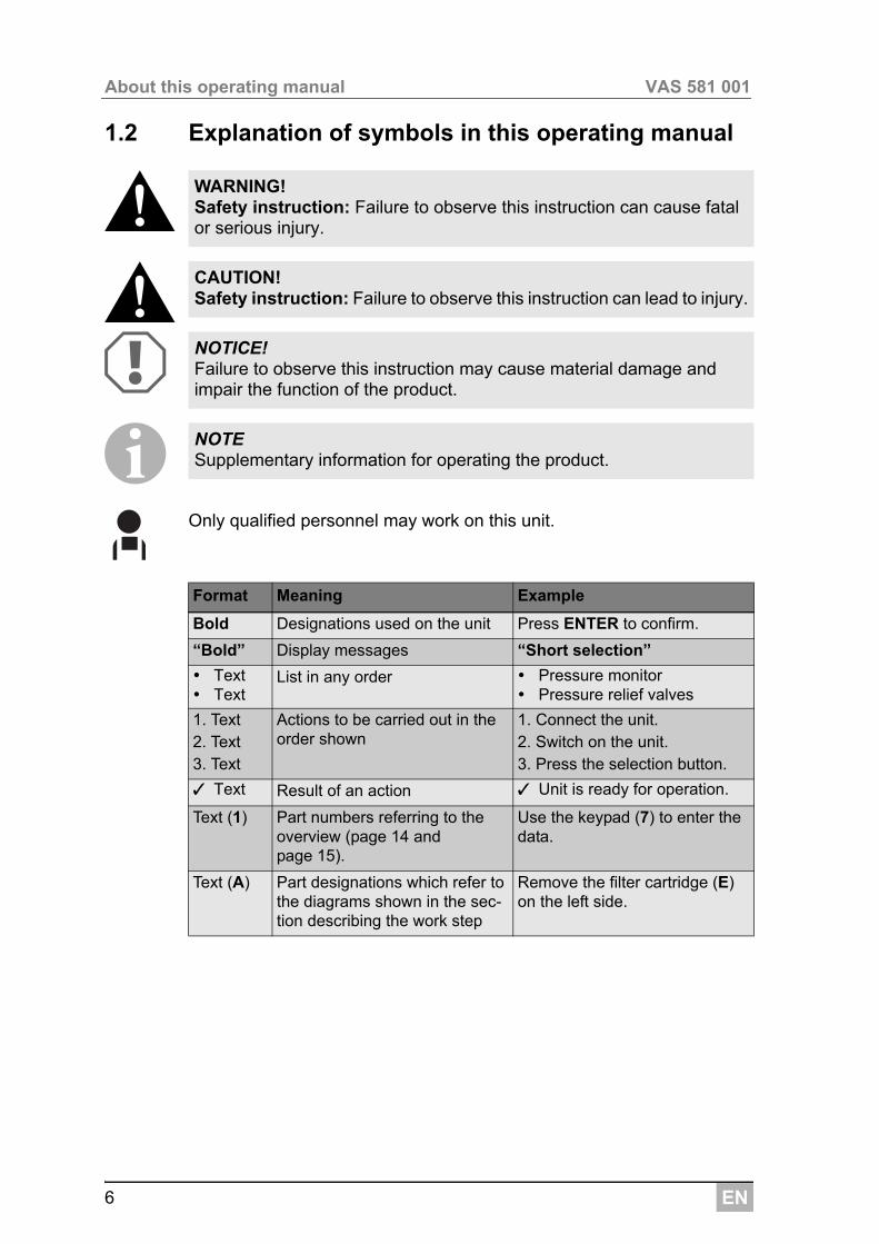
1.2 Explanation of symbols in this operating manual
!!AI
Only qualified personnel may work on this unit.
WARNING! Safety instruction: Failure to observe this instruction can cause fatal or serious injury.
CAUTION! Safety instruction: Failure to observe this instruction can lead to injury.
NOTICE! Failure to observe this instruction may cause material damage and impair the function of the product.
NOTE Supplementary information for operating the product.
Format Meaning Example
Bold Designations used on the unit Press ENTER to confirm.
“Bold” Display messages “Short selection”
Text Text
List in any order Pressure monitor Pressure relief valves
1. Text2. Text3. Text
Actions to be carried out in the order shown
1. Connect the unit.2. Switch on the unit.3. Press the selection button.
✓ Text Result of an action ✓ Unit is ready for operation.
Text (1) Part numbers referring to the overview (page 14 and page 15).
Use the keypad (7) to enter the data.
Text (A) Part designations which refer to the diagrams shown in the sec-tion describing the work step
Remove the filter cartridge (E) on the left side.
EN 7
VAS 581 001 Safety
2 SafetyThe manufacturer will not be held liable for claims for damage resulting from the following:
Damage to the unit resulting from mechanical influences and excess voltage
Alterations to the product without the express permission of the manufacturer
Use for purposes and operating equipment other than those described in the instruction manual
Repairs to the service unit which were not performed by qualified specialists
2.1 General safety instructions
The A/CServiceCenter may only be used by personnel who are able to demonstrate the appropriate specialist training and are familiar with the operation and basic principles of the A/CServiceCenter, air conditioning systems as well as refrigerant.
Read this operating manual carefully before starting up the A/CServiceCenter for the first time.
Only use the unit for its intended purpose.
Do not make modifications to the A/CServiceCenter.
Maintenance must not be carried out on the vehicle air conditioner when the engine is at operating temperature.
When performing maintenance on the vehicle air conditioner the surface temperature of attachment parts or surrounding parts must be less than 405 °C.
EN
Safety VAS 581 001
8
2.2 Operating the unit safely
Never expose the unit to heavy moisture.
Do not operate the unit outdoors when it is raining.
Do not operate the unit near heat sources (such as heaters) or in direct sunlight.
Do not operate the A/CServiceCenter in areas where there is a risk of explosion (for example battery charging rooms or spraying booths), see operating safety directive BGR 157/TRG 250, 280, 316.
Do not start up the A/CServiceCenter if it is damaged.
Each time you start up the unit or top up the A/CServiceCenter, first check whether the unit and all the service hoses are undamaged and that all valves are closed.
Always position the unit on level ground and secure the front wheels.
Only use approved refrigerant vessels with safety valves to refill the A/CServiceCenter.
Drain the service hoses before you undo the connections.
Only use R-1234yf refrigerant. If other refrigerants are mixed in, this can damage the A/CServiceCenter and the vehicle air conditioning system.
Only use WAECO UV additive. If you use other UV additives, it could cause damage to the A/CServiceCenter. This will invalidate any war-ranty.
Before you shut down the A/CServiceCenter, make sure that the selected programme has ended and that all valves are shut. Otherwise refrigerant can leak.
Always use the main switch of the A/CServiceCenter to switch it on and off. Do not leave the unit unattended when it is switched on.
Maintenance and repairs to the unit may only be performed by qualified and approved personnel from suitable and certified specialist companies.
Do not pump compressed air into the refrigerant lines of the A/CServiceCenter or the vehicle air conditioning system. A mixture of compressed air and refrigerant can be flammable or explosive.
EN 9
VAS 581 001 Safety
2.3 Handling refrigerant safely
Maintenance must not be carried out on the vehicle air conditioner when the engine is at operating temperature.
When performing maintenance on the vehicle air conditioner the surface temperature of attachment parts or surrounding parts must be less than 405 °C.
Wear personal safety equipment (safety goggles and protective gloves) and avoid coming into contact with the refrigerant. Contact with the refrig-erant draws out body heat and the affected areas can freeze.
Make sure that refrigerant is not able to escape and leak into the environ-ment during operation, when filling or draining refrigerant or during repair and service work. This adheres to environmental protection laws. It also avoids the difficulty or impossibility of detecting leaks in the vehicle or in the unit due to the presence of refrigerant in the vicinity of the unit.
Do not inhale refrigerant vapour. Although the vapour is non-toxic, it displaces the oxygen you need to breathe.
Refrigerant must not be used in low-lying spaces such as assembly pits or soakaways. Refrigerant is heavier than oxygen and therefore dis-places the air you need to breathe. This can cause a lack of oxygen when working in unventilated assembly pits.
Take suitable precautions to ensure that leaking refrigerant is not able to get into the drainage system.
Special information on refrigerant R-1234yf and safety measures as well as protecting personnel and objects, including fire protection can be found in the safety sheets of the refrigerant manufacturer.
EN
Safety VAS 581 001
10
2.4 Operational measures when using the unit
The operator must provide operating instructions according to TRG 402 for each filling system (A/CServiceCenter). These operating instructions must be used to train personnel in handling the unit.
The operator must ensure that personnel are instructed in the following points at least once a year:
Special dangers when dealing with compressed gases
Safety guidelines when dealing with compressed gases
Health precautions when dealing with compressed gases
Operating the unit and performing service work on the unit
The operator must ensure that personnel appointed to perform service and repair work as well as leak inspections are certified to deal with refrigerant and filling systems.
Certification and knowledge of the applicable guidelines and standards can be acquired from a training course at a chamber of trade, chamber of industry and commerce or at any other recognised training facility.
EN 11
VAS 581 001 Safety
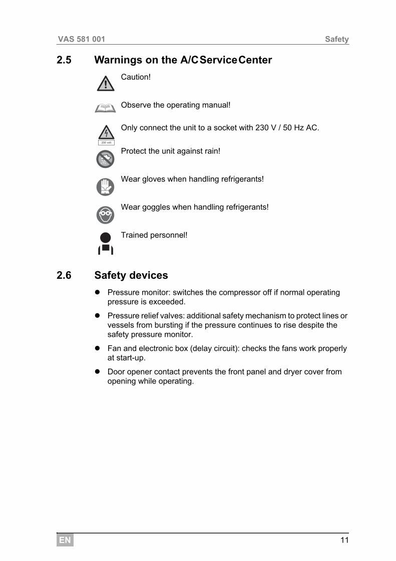
2.5 Warnings on the A/CServiceCenter
Caution!
Observe the operating manual!
Only connect the unit to a socket with 230 V / 50 Hz AC.
Protect the unit against rain!
Wear gloves when handling refrigerants!
Wear goggles when handling refrigerants!
Trained personnel!
2.6 Safety devices
Pressure monitor: switches the compressor off if normal operating pressure is exceeded.
Pressure relief valves: additional safety mechanism to protect lines or vessels from bursting if the pressure continues to rise despite the safety pressure monitor.
Fan and electronic box (delay circuit): checks the fans work properly at start-up.
Door opener contact prevents the front panel and dryer cover from opening while operating.
EN
Scope of delivery VAS 581 001
12
3 Scope of deliveryThe A/CServiceCenter and its accessories are carefully checked before shipping.
After delivery, check that all the parts listed below are present and undamaged.
If any parts are missing or damaged, notify the company responsible for transport immediately.
A
4 AccessoriesAvailable as accessories (not included in the scope of delivery):
Description
Bottle valve adapter for refrigerant bottles
Adapter for 500 ml fresh oil and UV contrast agent bottle
Closed, patented drained oil receptacle
Oil bottle 250 ml (2 items)
Protective unit cover
Goggles/gloves
Operating manual
NOTICE! For safe operation and calibration, you require R-1234yf refrigerant (not in scope of delivery).Refrigerant vessels are currently supplied with various connecting threads and adapters; these are not in the scope of delivery.
Description Item no.
Replacement filter with filter code for maintenance 4445900221
Protective unit cover 4445900081
Spare printer roll (thermal paper) (VPE 4) 4445900088
Safety goggles 8885400066
Protective gloves 8885400065
Vacuum pump oil (1000 ml) 8887200018
EN 13
VAS 581 001 Proper use
5 Proper useThe VAS 581 001 A/CServiceCenter (ASE 581 01 00 000) is designed for performing maintenance on vehicle air conditioning systems. The unit is designed for commercial use.
The A/CServiceCenter may only be operated by personnel who have the expertise required for servicing air conditioning systems.
This A/CServiceCenter may only be used to service vehicle air condition-ing systems in which R-1234yf refrigerant is used.
The A/CServiceCenter is only suitable for approved operating fluids.
EN
Overview of the A/CServiceCenter VAS 581 001
14
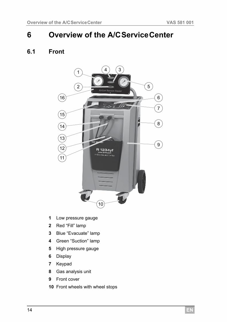
6 Overview of the A/CServiceCenter
6.1 Front
1 Low pressure gauge
2 Red “Fill” lamp
3 Blue “Evacuate” lamp
4 Green “Suction” lamp
5 High pressure gauge
6 Display
7 Keypad
8 Gas analysis unit
9 Front cover
10 Front wheels with wheel stops
14
13
34
5
10
8
9
7
6
2
16
12
11
15
1
EN 15
VAS 581 001 Overview of the A/CServiceCenter
11 Service hose for low pressure connection (blue)
12 Service hose for high pressure connection (red)
13 Service coupling for high pressure connection (red)
14 Service coupling for low pressure connection (blue)
15 Printer
16 Display unit
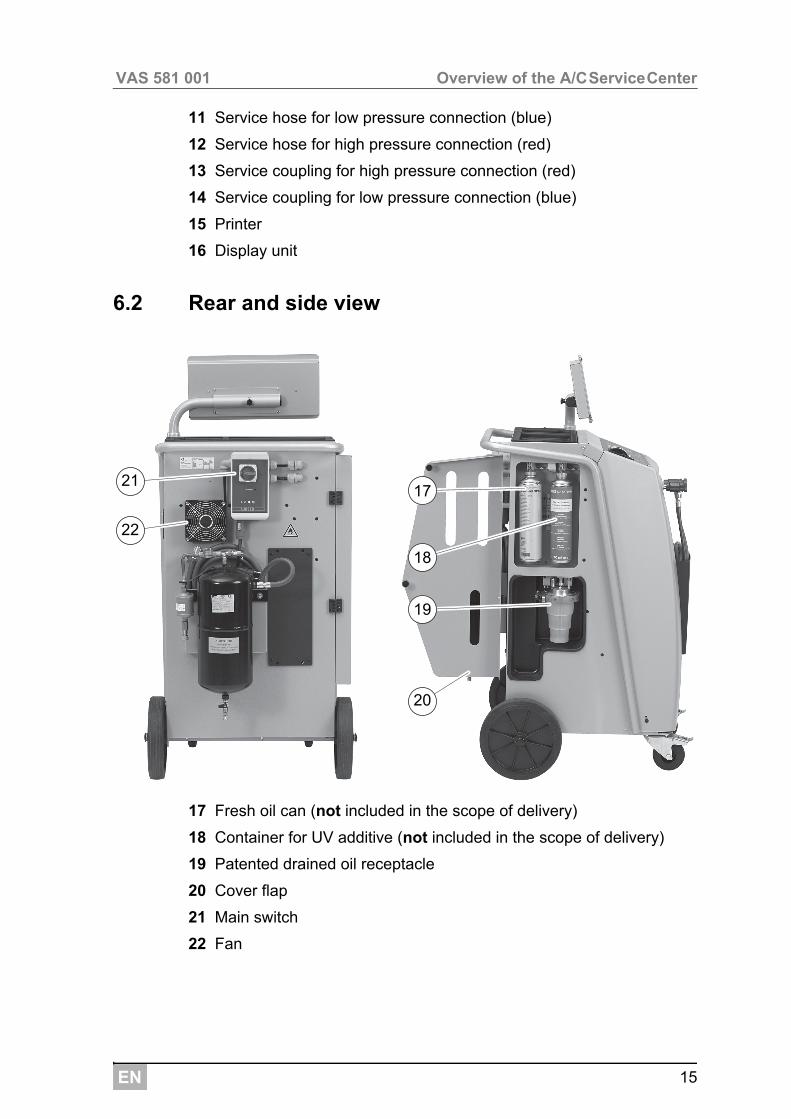
6.2 Rear and side view
17 Fresh oil can (not included in the scope of delivery)
18 Container for UV additive (not included in the scope of delivery)
19 Patented drained oil receptacle
20 Cover flap
21 Main switch
22 Fan
19
18
17
20
22
21
EN
Initial start-up VAS 581 001
16
7 Initial start-up
7.1 Procedure for the internal leak inspection
The internal unit pressure test is performed automatically once a day.
Firstly, the service hose connections to an air conditioning system are checked and to see whether the service connectors are installed.
If pressure is still in the hoses, it causes an error. If the service hoses are full, a refrigerant analysis is performed and the refrigerant is then recycled if the “Analysis OK” message appears. Afterwards, the vacuum test is performed. Several parts of the unit are evacuated. Once the vacuum test has been carried out successfully, the parts of the unit are filled with refrigerant – now a 6 minute pressure test is done with all the solenoid valves open to immediately determine a drop in pressure. After successful completion, the refrigerant is suctioned off and the unit is available for service work.
7.2 Setting up and switching on
1. Wheel the A/CServiceCenter to the workplace and lock the front wheels (10).
I2. Connect the A/CServiceCenter to the mains.
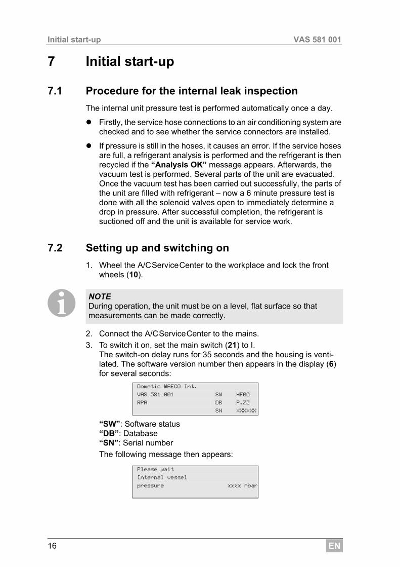
3. To switch it on, set the main switch (21) to I. The switch-on delay runs for 35 seconds and the housing is venti-lated. The software version number then appears in the display (6) for several seconds:
“SW”: Software status“DB”: Database“SN”: Serial number
The following message then appears:
NOTE During operation, the unit must be on a level, flat surface so that measurements can be made correctly.
Dometic WAECO Int.
VAS 581 001 SW HF00
RPA DB P.ZZ
SN XXXXXX
Please wait
Internal vessel
pressure xxxx mbar
EN 17
VAS 581 001 Initial start-up
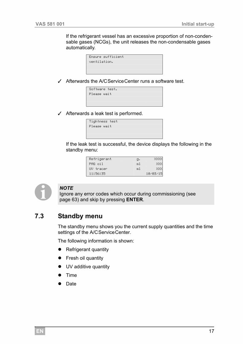
If the refrigerant vessel has an excessive proportion of non-conden-sable gases (NCGs), the unit releases the non-condensable gases automatically.
✓ Afterwards the A/CServiceCenter runs a software test.
✓ Afterwards a leak test is performed.
If the leak test is successful, the device displays the following in the standby menu:
I7.3 Standby menu
The standby menu shows you the current supply quantities and the time settings of the A/CServiceCenter.
The following information is shown:
Refrigerant quantity
Fresh oil quantity
UV additive quantity
Time
Date
Ensure sufficient
ventilation.
Software test.
Please wait
Tightness test
Please wait
Refrigerant g. XXXX
PAG oil ml XXX
UV tracer ml XXX
11:56:35 10/03/15
NOTE Ignore any error codes which occur during commissioning (see page 63) and skip by pressing ENTER.
EN
Initial start-up VAS 581 001
18
7.4 Language selection
1. Press the cursor keys or to access the basic menu.
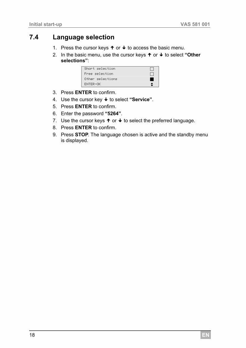
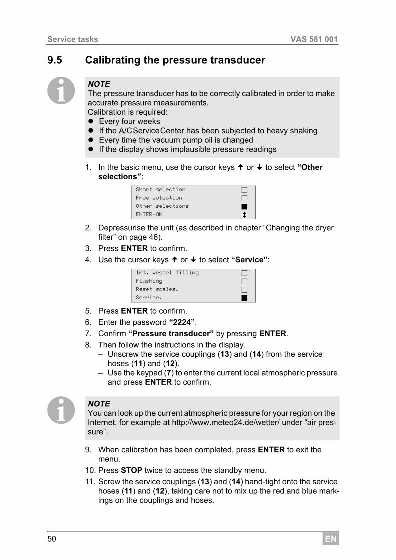
2. In the basic menu, use the cursor keys or to select “Other selections”:
3. Press ENTER to confirm.
4. Use the cursor key to select “Service”.
5. Press ENTER to confirm.
6. Enter the password “5264”.
7. Use the cursor keys or to select the preferred language.
8. Press ENTER to confirm.
9. Press STOP. The language chosen is active and the standby menu is displayed.
Short selection
Free selection
Other selections
ENTER-OK
EN 19
VAS 581 001 Initial start-up
7.5 Entering company data
The company data is printed out with every service log.
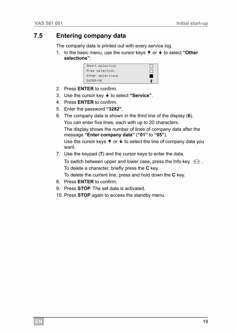
1. In the basic menu, use the cursor keys or to select “Other selections”:
2. Press ENTER to confirm.
3. Use the cursor key to select “Service”.
4. Press ENTER to confirm.
5. Enter the password “3282”.
6. The company data is shown in the third line of the display (6).
You can enter five lines, each with up to 20 characters.
The display shows the number of lines of company data after the message “Enter company data” (“01” to “05”).
Use the cursor keys or to select the line of company data you want.
7. Use the keypad (7) and the cursor keys to enter the data.
To switch between upper and lower case, press the Info key .
To delete a character, briefly press the C key.
To delete the current line, press and hold down the C key.
8. Press ENTER to confirm.
9. Press STOP. The set data is activated.
10. Press STOP again to access the standby menu.
Short selection
Free selection
Other selections
ENTER-OK
EN
Initial start-up VAS 581 001
20
7.6 Entering the date and time
The date and the time are printed along with the company data on every service log.
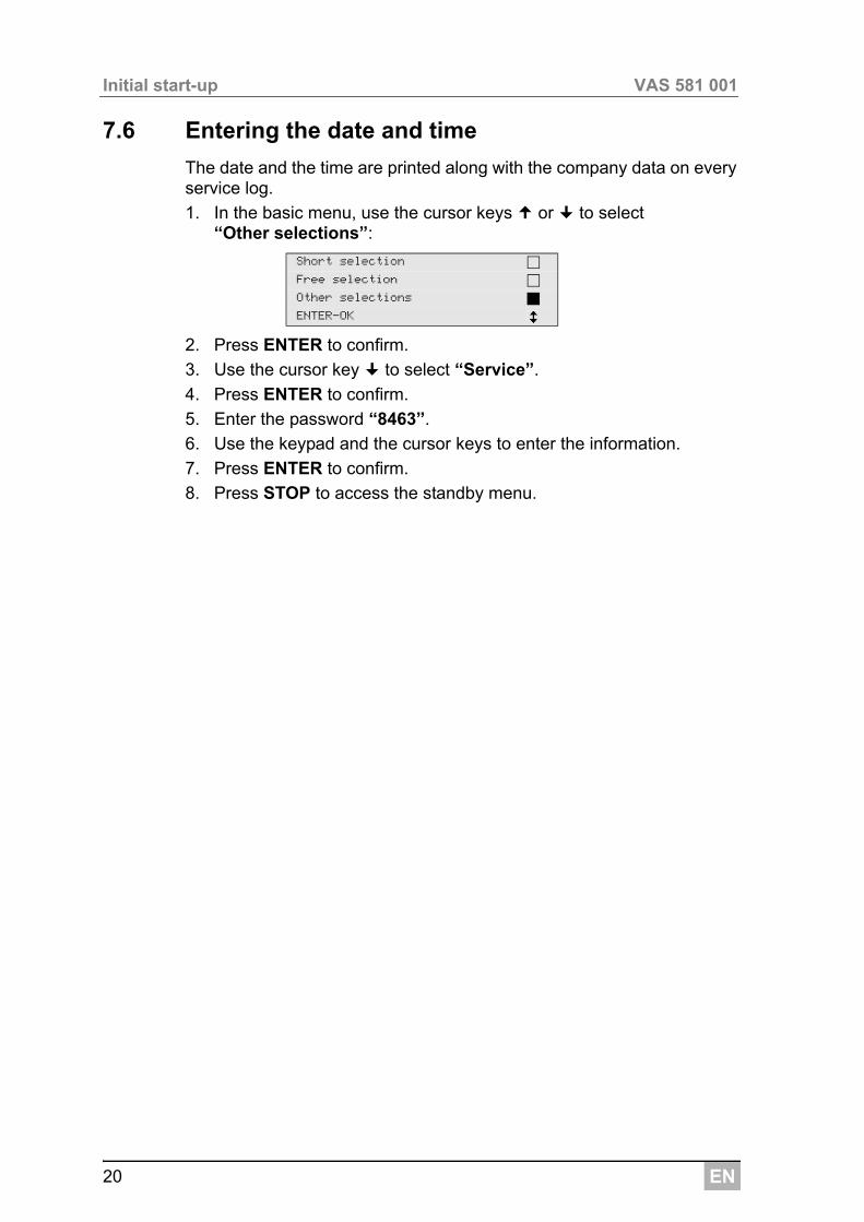
1. In the basic menu, use the cursor keys or to select “Other selections”:
2. Press ENTER to confirm.
3. Use the cursor key to select “Service”.
4. Press ENTER to confirm.
5. Enter the password “8463”.
6. Use the keypad and the cursor keys to enter the information.
7. Press ENTER to confirm.
8. Press STOP to access the standby menu.
Short selection
Free selection
Other selections
ENTER-OK
EN 21
VAS 581 001 Initial start-up
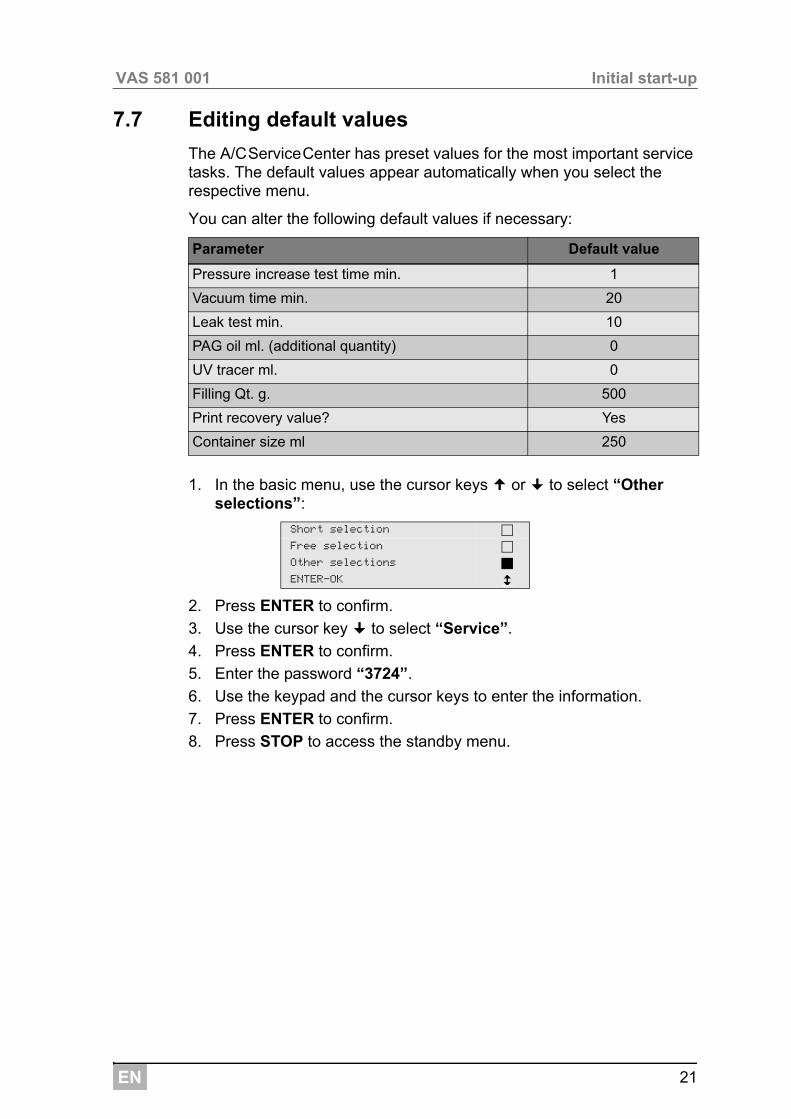
7.7 Editing default values
The A/CServiceCenter has preset values for the most important service tasks. The default values appear automatically when you select the respective menu.
You can alter the following default values if necessary:
1. In the basic menu, use the cursor keys or to select “Other selections”:
2. Press ENTER to confirm.
3. Use the cursor key to select “Service”.
4. Press ENTER to confirm.
5. Enter the password “3724”.
6. Use the keypad and the cursor keys to enter the information.
7. Press ENTER to confirm.
8. Press STOP to access the standby menu.
Parameter Default value
Pressure increase test time min. 1
Vacuum time min. 20
Leak test min. 10
PAG oil ml. (additional quantity) 0
UV tracer ml. 0
Filling Qt. g. 500
Print recovery value? Yes
Container size ml 250
Short selection
Free selection
Other selections
ENTER-OK
EN
Initial start-up VAS 581 001
22
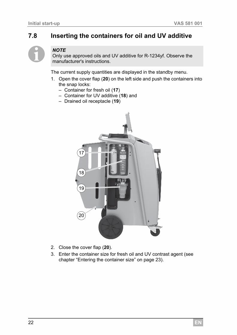
7.8 Inserting the containers for oil and UV additive
IThe current supply quantities are displayed in the standby menu.
1. Open the cover flap (20) on the left side and push the containers into the snap locks:– Container for fresh oil (17)– Container for UV additive (18) and– Drained oil receptacle (19)
2. Close the cover flap (20).
3. Enter the container size for fresh oil and UV contrast agent (see chapter “Entering the container size” on page 23).
NOTE Only use approved oils and UV additive for R-1234yf. Observe the manufacturer's instructions.
19
18
17
20
EN 23
VAS 581 001 Initial start-up
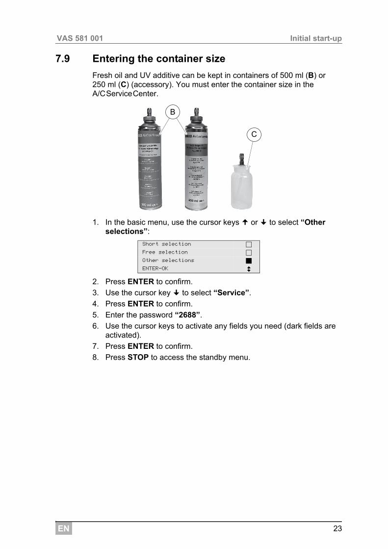
7.9 Entering the container size
Fresh oil and UV additive can be kept in containers of 500 ml (B) or 250 ml (C) (accessory). You must enter the container size in the A/CServiceCenter.
1. In the basic menu, use the cursor keys or to select “Other selections”:
2. Press ENTER to confirm.
3. Use the cursor key to select “Service”.
4. Press ENTER to confirm.
5. Enter the password “2688”.
6. Use the cursor keys to activate any fields you need (dark fields are activated).
7. Press ENTER to confirm.
8. Press STOP to access the standby menu.
Short selection
Free selection
Other selections
ENTER-OK
C
B
EN
Initial start-up VAS 581 001
24
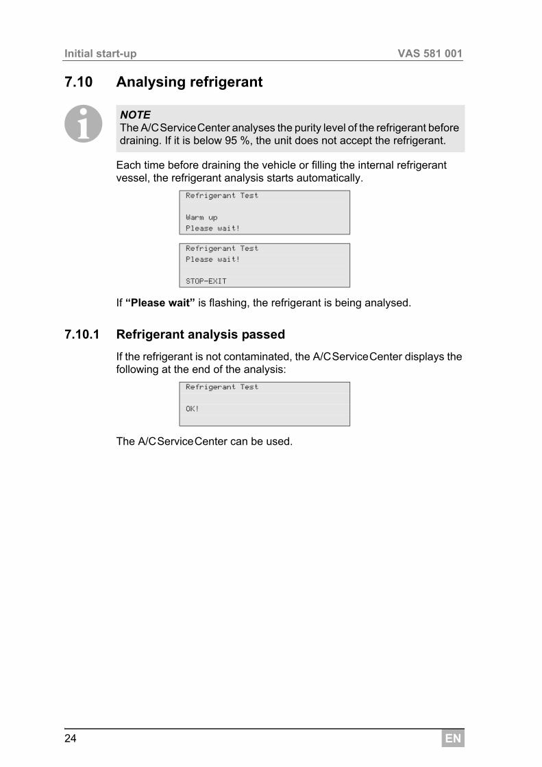
7.10 Analysing refrigerant
IEach time before draining the vehicle or filling the internal refrigerant vessel, the refrigerant analysis starts automatically.
If “Please wait” is flashing, the refrigerant is being analysed.
7.10.1 Refrigerant analysis passed
If the refrigerant is not contaminated, the A/CServiceCenter displays the following at the end of the analysis:
The A/CServiceCenter can be used.
NOTE The A/CServiceCenter analyses the purity level of the refrigerant before draining. If it is below 95 %, the unit does not accept the refrigerant.
Refrigerant Test
Warm up
Please wait!
Refrigerant Test
Please wait!
STOP-EXIT
Refrigerant Test
OK!
EN 25
VAS 581 001 Initial start-up
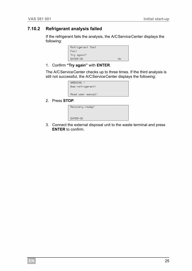
7.10.2 Refrigerant analysis failed
If the refrigerant fails the analysis, the A/CServiceCenter displays the following:
1. Confirm “Try again” with ENTER.
The A/CServiceCenter checks up to three times. If the third analysis is still not successful, the A/CServiceCenter displays the following:
2. Press STOP.
3. Connect the external disposal unit to the waste terminal and press ENTER to confirm.
Refrigerant Test
Fail
Try again?
ENTER-OK No
WARNING !
Bad refrigerant!
Read user manual!
Recovery ready?
ENTER-OK
EN
Initial start-up VAS 581 001
26
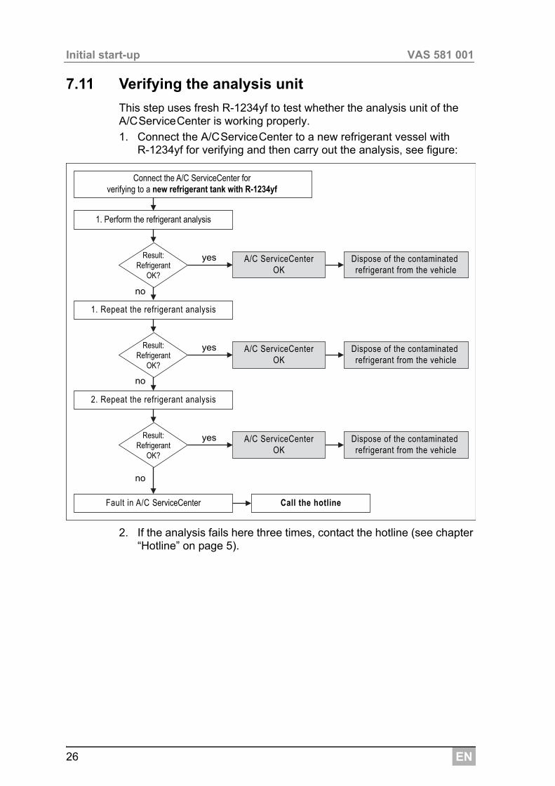
7.11 Verifying the analysis unit
This step uses fresh R-1234yf to test whether the analysis unit of the A/CServiceCenter is working properly.
1. Connect the A/CServiceCenter to a new refrigerant vessel with R-1234yf for verifying and then carry out the analysis, see figure:
2. If the analysis fails here three times, contact the hotline (see chapter “Hotline” on page 5).
yes
no
no
no
yes
yes
A/C ServiceCenterOK
A/C ServiceCenterOK
A/C ServiceCenterOK
1. Perform the refrigerant analysis
Connect the A/C ServiceCenter for verifying to a new refrigerant tank with R-1234yf
Result:Refrigerant
OK?
Result:Refrigerant
OK?
Result:Refrigerant
OK?
1. Repeat the refrigerant analysis
2. Repeat the refrigerant analysis
Fault in A/C ServiceCenter Call the hotline
Dispose of the contaminated refrigerant from the vehicle
Dispose of the contaminated refrigerant from the vehicle
Dispose of the contaminated refrigerant from the vehicle
EN 27
VAS 581 001 Initial start-up
7.12 Filling up the internal refrigerant container
IWhen the A/CServiceCenter is started for the first time, the internal refrig-erant vessel must be filled from an external refrigerant vessel with at least 2000 g of refrigerant.
The unit displays error message 12.
Press STOP to confirm.
IThe current supply quantities are displayed in the standby menu.
There are three different types of refrigerant vessel available:
Refrigerant vessels without rising pipe:These refrigerant vessels have one connection.When filling the A/CServiceCenter, the connection must be on the bottom (turn the vessel upside down).
Refrigerant vessels with rising pipe:These refrigerant vessels have one connection.When filling the A/CServiceCenter, the connection must be at the top (place the vessel).
Refrigerant vessels with rising pipe:These refrigerant vessels have two connections. To top up the A/CServiceCenter, use the connection marked with L (= liquid).When filling the A/CServiceCenter, the connection must be at the top (place the vessel).
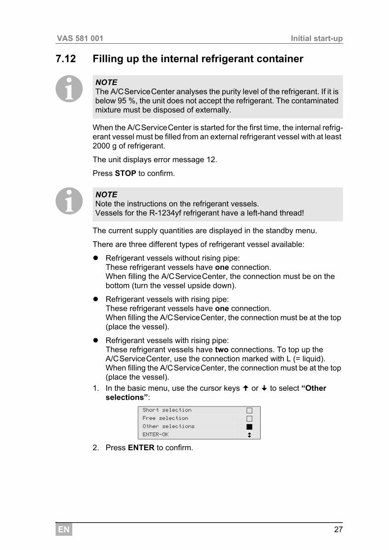
1. In the basic menu, use the cursor keys or to select “Other selections”:
2. Press ENTER to confirm.
NOTE The A/CServiceCenter analyses the purity level of the refrigerant. If it is below 95 %, the unit does not accept the refrigerant. The contaminated mixture must be disposed of externally.
NOTE Note the instructions on the refrigerant vessels. Vessels for the R-1234yf refrigerant have a left-hand thread!
Short selection
Free selection
Other selections
ENTER-OK
EN
Initial start-up VAS 581 001
28
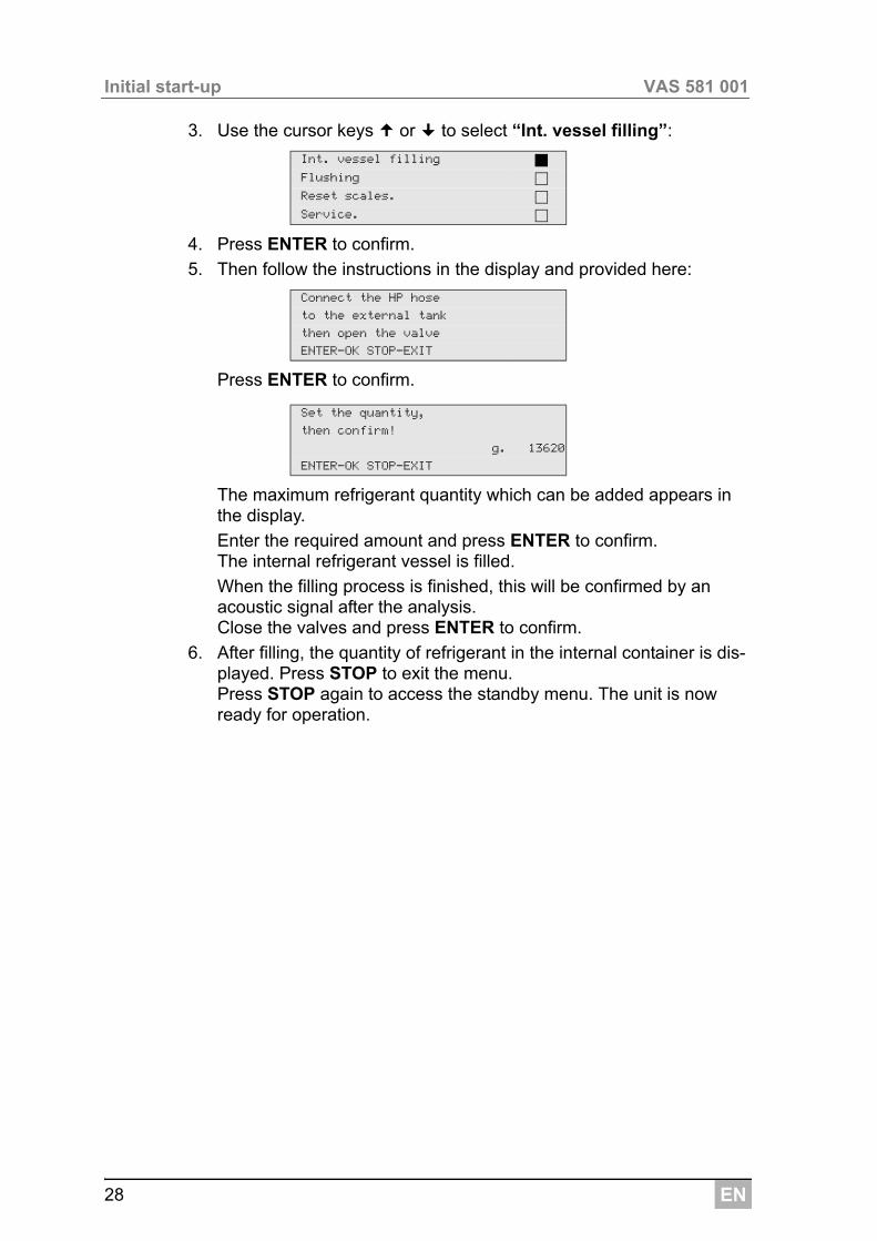
3. Use the cursor keys or to select “Int. vessel filling”:
4. Press ENTER to confirm.
5. Then follow the instructions in the display and provided here:
Press ENTER to confirm.
The maximum refrigerant quantity which can be added appears in the display.
Enter the required amount and press ENTER to confirm.The internal refrigerant vessel is filled.
When the filling process is finished, this will be confirmed by an acoustic signal after the analysis.Close the valves and press ENTER to confirm.
6. After filling, the quantity of refrigerant in the internal container is dis-played. Press STOP to exit the menu.Press STOP again to access the standby menu. The unit is now ready for operation.
Int. vessel filling
Flushing
Reset scales.
Service.
Connect the HP hose
to the external tank
then open the valve
ENTER-OK STOP-EXIT
Set the quantity,
then confirm!
g. 13620
ENTER-OK STOP-EXIT
EN 29
VAS 581 001 Operation
8 Operation
A8.1 Short selection
I
1. First fit the service hoses for the A/CServiceCenter to the vehicle air conditioning system, and open the service couplings.
2. Press the cursor key or to access the basic menu.
NOTICE! When the air conditioning system is being serviced, the engine and the air conditioning unit must be switched off.
NOTE A fully automatic air conditioning service is started using the “Short selection” menu. You only have to enter the filling quantity as shown on the label in the vehicle.The following actions are performed automatically in succession in the “Short selection” menu: Performing the refrigerant analysis (see chapter “Analysing
refrigerant” on page 24) Extraction of the refrigerant Recycling the refrigerant (purity = SAE J 2099) Pressure rise test Draining the used oil Evacuating the system Before working on the vehicle air conditioner, a leak inspection must
be carried out. The air conditioner is filled with a sample refrigerant. The pressure in the air conditioner must remain constant over a period of 5 minutes. The air conditioning unit can only be completely filled if this test has been successfully completed. The sample filling is then drained and the air conditioner evacuated. The final filling quantity is completely filled up to ensure high filling accuracy.
Leak test / vacuum check Filling with new oil to the required quantity Filling with UV additive Filling of refrigerantAfter each process has been performed, a service report is printed. Subsequent actions are only initiated once the preceding action has been completed successfully.
EN
Operation VAS 581 001
30
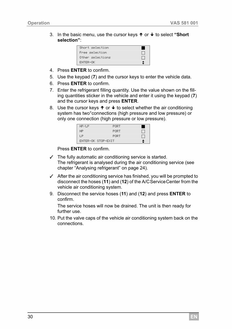
3. In the basic menu, use the cursor keys or to select “Short selection”:
4. Press ENTER to confirm.
5. Use the keypad (7) and the cursor keys to enter the vehicle data.
6. Press ENTER to confirm.
7. Enter the refrigerant filling quantity. Use the value shown on the fill-ing quantities sticker in the vehicle and enter it using the keypad (7) and the cursor keys and press ENTER.
8. Use the cursor keys or to select whether the air conditioning system has two°connections (high pressure and low pressure) or only one connection (high pressure or low pressure).
Press ENTER to confirm.
✓ The fully automatic air conditioning service is started. The refrigerant is analysed during the air conditioning service (see chapter “Analysing refrigerant” on page 24).
✓ After the air conditioning service has finished, you will be prompted to disconnect the hoses (11) and (12) of the A/CServiceCenter from the vehicle air conditioning system.
9. Disconnect the service hoses (11) and (12) and press ENTER to confirm.
The service hoses will now be drained. The unit is then ready for further use.
10. Put the valve caps of the vehicle air conditioning system back on the connections.
Short selection
Free selection
Other selections
ENTER-OK
HP/LP PORT
HP PORT
LP PORT
ENTER-OK STOP-EXIT
EN 31
VAS 581 001 Operation
8.2 User codes
It is possible to protect the air conditioning service station from unauthor-ised access using personal user codes. When this function is activated, the system queries the user code after being switched on, and the station cannot be started without it. Up to 10 different users can be created with individual codes.
8.2.1 Creating user codes
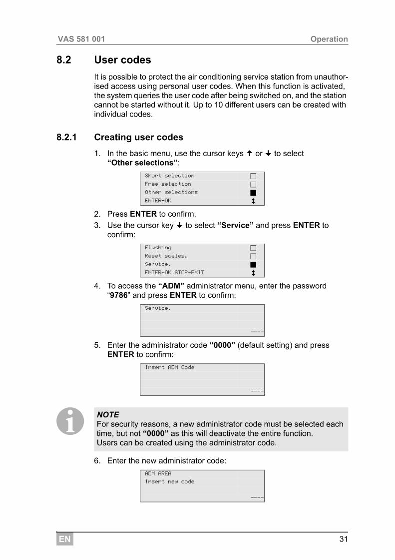
1. In the basic menu, use the cursor keys or to select “Other selections”:
2. Press ENTER to confirm.
3. Use the cursor key to select “Service” and press ENTER to confirm:
4. To access the “ADM” administrator menu, enter the password “9786” and press ENTER to confirm:
5. Enter the administrator code “0000” (default setting) and press ENTER to confirm:
I6. Enter the new administrator code:
Short selection
Free selection
Other selections
ENTER-OK
Flushing
Reset scales.
Service.
ENTER-OK STOP-EXIT
Service.
----
Insert ADM Code
----
NOTE For security reasons, a new administrator code must be selected each time, but not “0000” as this will deactivate the entire function.Users can be created using the administrator code.
ADM AREA
Insert new code
----
EN
Operation VAS 581 001
32
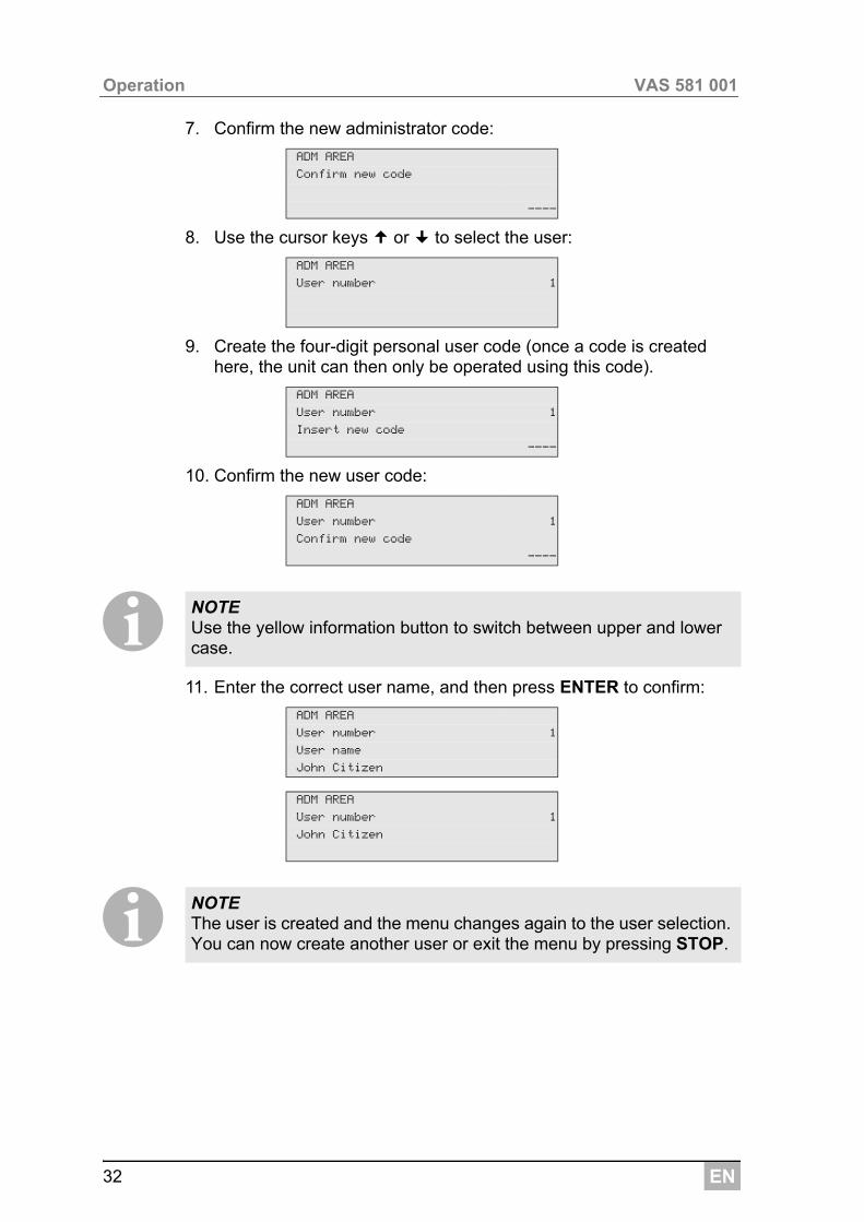
7. Confirm the new administrator code:
8. Use the cursor keys or to select the user:
9. Create the four-digit personal user code (once a code is created here, the unit can then only be operated using this code).
10. Confirm the new user code:
I11. Enter the correct user name, and then press ENTER to confirm:
I
ADM AREA
Confirm new code
----
ADM AREA
User number 1
ADM AREA
User number 1
Insert new code
----
ADM AREA
User number 1
Confirm new code
----
NOTE Use the yellow information button to switch between upper and lower case.
ADM AREA
User number 1
User name
John Citizen
ADM AREA
User number 1
John Citizen
NOTE The user is created and the menu changes again to the user selection. You can now create another user or exit the menu by pressing STOP.
EN 33
VAS 581 001 Operation
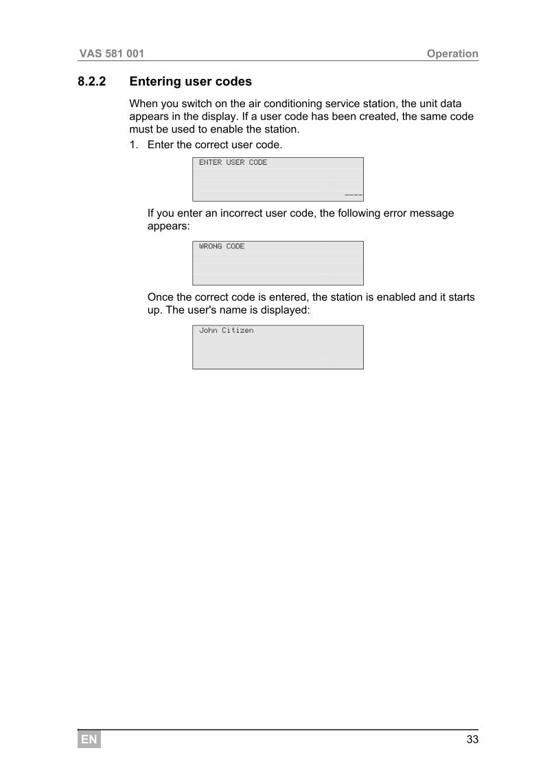
8.2.2 Entering user codes
When you switch on the air conditioning service station, the unit data appears in the display. If a user code has been created, the same code must be used to enable the station.
1. Enter the correct user code.
If you enter an incorrect user code, the following error message appears:
Once the correct code is entered, the station is enabled and it starts up. The user's name is displayed:
ENTER USER CODE
----
WRONG CODE
John Citizen
EN
Operation VAS 581 001
34
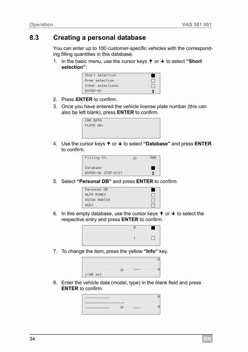
8.3 Creating a personal database
You can enter up to 100 customer-specific vehicles with the correspond-ing filling quantities in this database.
1. In the basic menu, use the cursor keys or to select “Short selection”:
2. Press ENTER to confirm.
3. Once you have entered the vehicle license plate number (this can also be left blank), press ENTER to confirm.
4. Use the cursor keys or to select “Database” and press ENTER to confirm.
5. Select “Personal DB” and press ENTER to confirm.
6. In this empty database, use the cursor keys or to select the respective entry and press ENTER to confirm.
7. To change the item, press the yellow “Info” key.
8. Enter the vehicle data (model, type) in the blank field and press ENTER to confirm.
Short selection
Free selection
Other selections
ENTER-OK
CAR DATA
PLATE NR:
Filling Qt. g. 500
Database
ENTER-OK STOP-EXIT
Personal DB
ALFA ROMEO
ASTON MARTIN
AUDI
0
1
0
g. --- 0
i-DB set
____________ 0
___________________
____________ g. ___ 0
EN 35
VAS 581 001 Operation
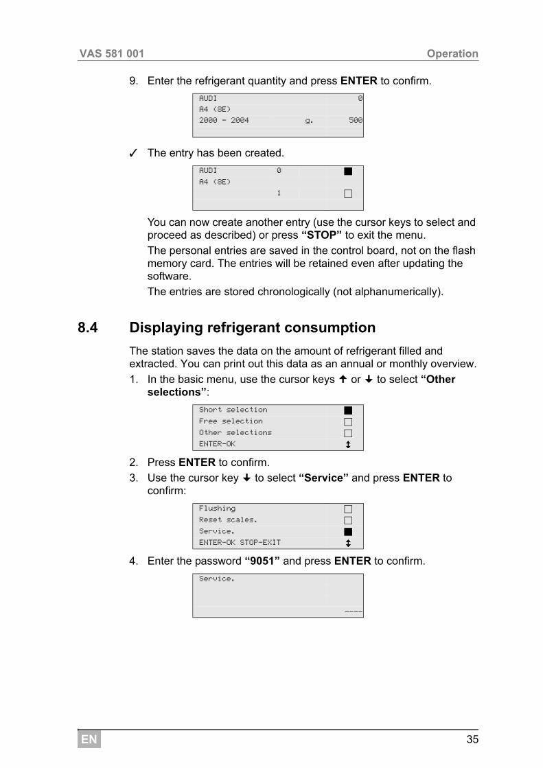
9. Enter the refrigerant quantity and press ENTER to confirm.
✓ The entry has been created.
You can now create another entry (use the cursor keys to select and proceed as described) or press “STOP” to exit the menu.
The personal entries are saved in the control board, not on the flash memory card. The entries will be retained even after updating the software.
The entries are stored chronologically (not alphanumerically).
8.4 Displaying refrigerant consumption
The station saves the data on the amount of refrigerant filled and extracted. You can print out this data as an annual or monthly overview.
1. In the basic menu, use the cursor keys or to select “Other selections”:
2. Press ENTER to confirm.
3. Use the cursor key to select “Service” and press ENTER to confirm:
4. Enter the password “9051” and press ENTER to confirm.
AUDI 0
A4 (8E)
2000 - 2004 g. 500
AUDI 0
A4 (8E)
1
Short selection
Free selection
Other selections
ENTER-OK
Flushing
Reset scales.
Service.
ENTER-OK STOP-EXIT
Service.
----
EN
Operation VAS 581 001
36
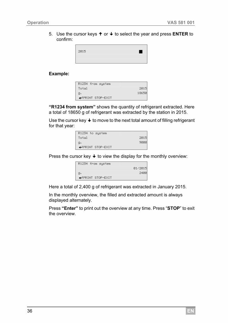
5. Use the cursor keys or to select the year and press ENTER to confirm:
Example:
“R1234 from system” shows the quantity of refrigerant extracted. Here a total of 18650 g of refrigerant was extracted by the station in 2015.
Use the cursor key to move to the next total amount of filling refrigerant for that year:
Press the cursor key to view the display for the monthly overview:
Here a total of 2,400 g of refrigerant was extracted in January 2015.
In the monthly overview, the filled and extracted amount is always displayed alternately.
Press “Enter” to print out the overview at any time. Press “STOP” to exit the overview.
2015
R1234 from system
Total 2015
g. 18650
PRINT STOP-EXIT
R1234 to system
Total 2015
g. 9000
PRINT STOP-EXIT
R1234 from system
01/2015
g. 2400
PRINT STOP-EXIT
EN 37
VAS 581 001 Operation
8.5 Free selection
I
The following three processes can performed individually in the “Free selection” menu:
Recycling phase: analysing the refrigerant (see chapter “Analysing refrigerant” on page 24), extraction, recycling of the refrigerant, pres-sure rise test, draining the waste oil.
Vacuum phase: evacuating the system, leak test / vacuum check.
Filling phase: Before working on the vehicle air conditioner, a leak inspection must be carried out. The air conditioner is filled with a sample of refrigerant. The pressure in the air conditioner must remain constant over a period of 5 minutes. The air conditioner can only be completely filled if this test has been successfully completed. The sample filling is then drained and the air conditioner evacuated. The final filling quantity is completely filled up to ensure high filling accuracy.Filling with fresh oil, filling of UV additive, filling of refrigerant.
After each process has been performed, a service report is printed.
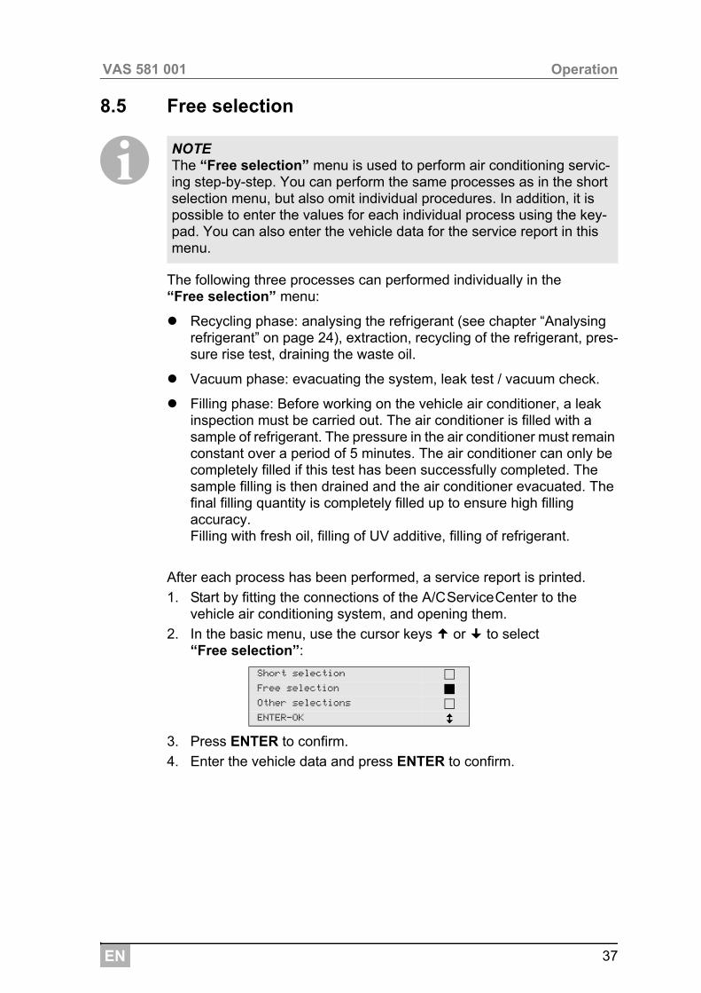
1. Start by fitting the connections of the A/CServiceCenter to the vehicle air conditioning system, and opening them.
2. In the basic menu, use the cursor keys or to select “Free selection”:
3. Press ENTER to confirm.
4. Enter the vehicle data and press ENTER to confirm.
NOTE The “Free selection” menu is used to perform air conditioning servic-ing step-by-step. You can perform the same processes as in the short selection menu, but also omit individual procedures. In addition, it is possible to enter the values for each individual process using the key-pad. You can also enter the vehicle data for the service report in this menu.
Short selection
Free selection
Other selections
ENTER-OK
EN
Operation VAS 581 001
38
8.5.1 Recovery phase
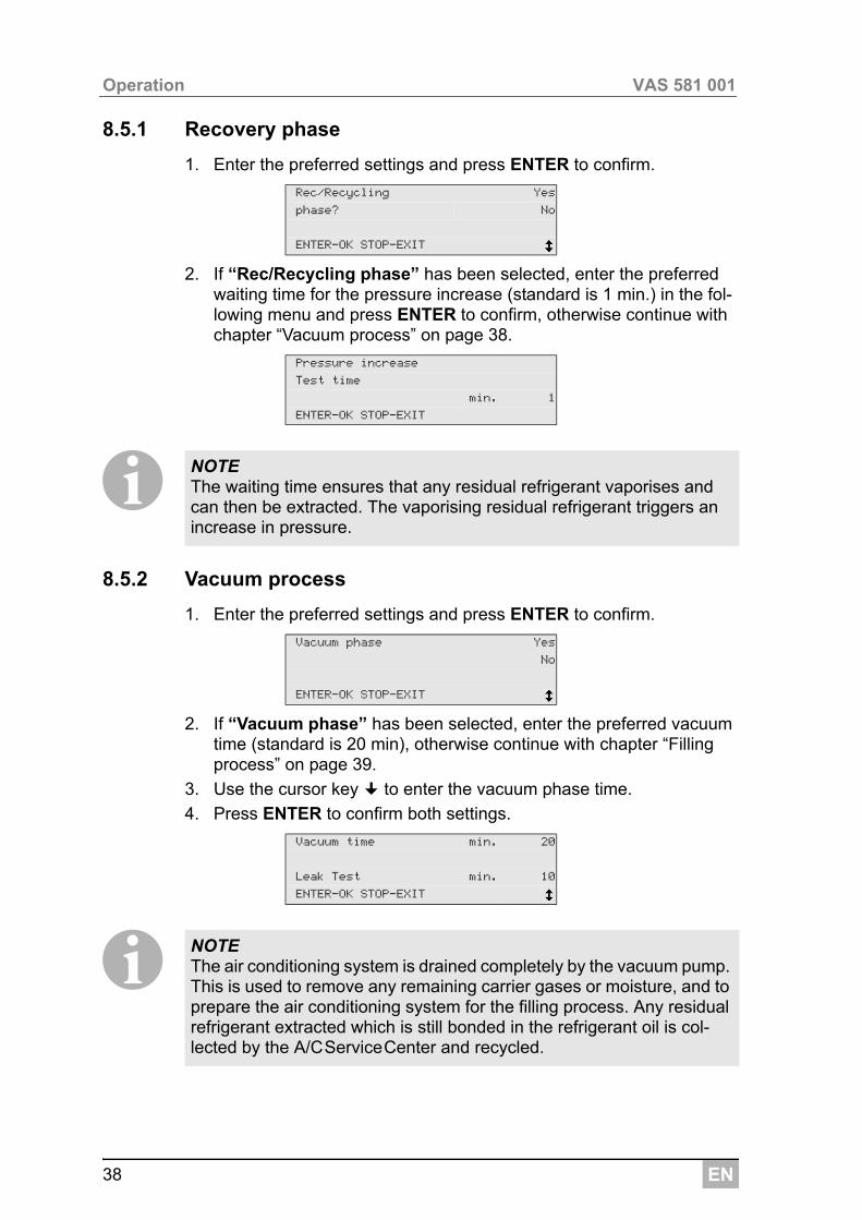
1. Enter the preferred settings and press ENTER to confirm.
2. If “Rec/Recycling phase” has been selected, enter the preferred waiting time for the pressure increase (standard is 1 min.) in the fol-lowing menu and press ENTER to confirm, otherwise continue with chapter “Vacuum process” on page 38.
I8.5.2 Vacuum process
1. Enter the preferred settings and press ENTER to confirm.
2. If “Vacuum phase” has been selected, enter the preferred vacuum time (standard is 20 min), otherwise continue with chapter “Filling process” on page 39.
3. Use the cursor key to enter the vacuum phase time.
4. Press ENTER to confirm both settings.
I
Rec/Recycling Yes
phase? No
ENTER-OK STOP-EXIT
Pressure increase
Test time
min. 1
ENTER-OK STOP-EXIT
NOTE The waiting time ensures that any residual refrigerant vaporises and can then be extracted. The vaporising residual refrigerant triggers an increase in pressure.
Vacuum phase Yes
No
ENTER-OK STOP-EXIT
Vacuum time min. 20
Leak Test min. 10
ENTER-OK STOP-EXIT
NOTE The air conditioning system is drained completely by the vacuum pump. This is used to remove any remaining carrier gases or moisture, and to prepare the air conditioning system for the filling process. Any residual refrigerant extracted which is still bonded in the refrigerant oil is col-lected by the A/CServiceCenter and recycled.
EN 39
VAS 581 001 Operation
8.5.3 Filling process
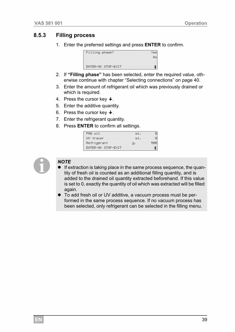
1. Enter the preferred settings and press ENTER to confirm.
2. If “Filling phase” has been selected, enter the required value, oth-erwise continue with chapter “Selecting connections” on page 40.
3. Enter the amount of refrigerant oil which was previously drained or which is required.
4. Press the cursor key .
5. Enter the additive quantity.
6. Press the cursor key .
7. Enter the refrigerant quantity.
8. Press ENTER to confirm all settings.
I
Filling phase? Yes
No
ENTER-OK STOP-EXIT
PAG oil ml. 0
UV tracer ml. 0
Refrigerant g. 500
ENTER-OK STOP-EXIT
NOTE If extraction is taking place in the same process sequence, the quan-
tity of fresh oil is counted as an additional filling quantity, and is added to the drained oil quantity extracted beforehand. If this value is set to 0, exactly the quantity of oil which was extracted will be filled again.
To add fresh oil or UV additive, a vacuum process must be per-formed in the same process sequence. If no vacuum process has been selected, only refrigerant can be selected in the filling menu.
EN
Operation VAS 581 001
40
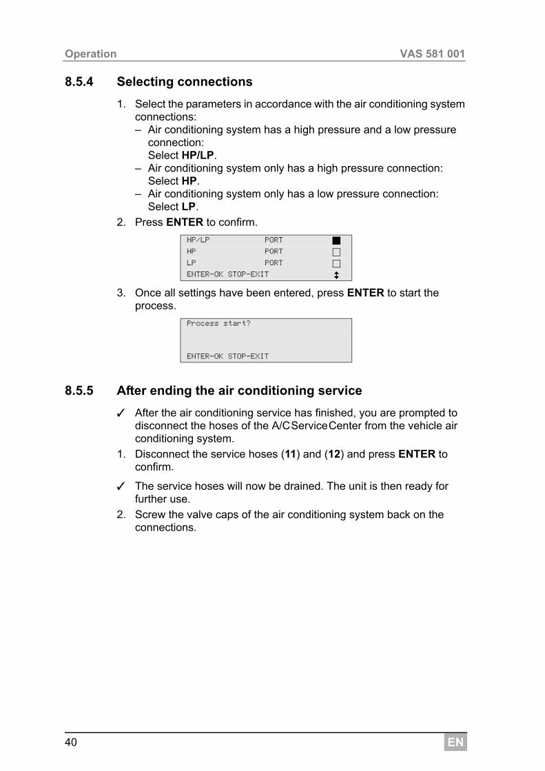
8.5.4 Selecting connections
1. Select the parameters in accordance with the air conditioning system connections:– Air conditioning system has a high pressure and a low pressure
connection: Select HP/LP.
– Air conditioning system only has a high pressure connection: Select HP.
– Air conditioning system only has a low pressure connection: Select LP.
2. Press ENTER to confirm.
3. Once all settings have been entered, press ENTER to start the process.
8.5.5 After ending the air conditioning service
✓ After the air conditioning service has finished, you are prompted to disconnect the hoses of the A/CServiceCenter from the vehicle air conditioning system.
1. Disconnect the service hoses (11) and (12) and press ENTER to confirm.
✓ The service hoses will now be drained. The unit is then ready for further use.
2. Screw the valve caps of the air conditioning system back on the connections.
HP/LP PORT
HP PORT
LP PORT
ENTER-OK STOP-EXIT
Process start?
ENTER-OK STOP-EXIT
EN 41
VAS 581 001 Operation
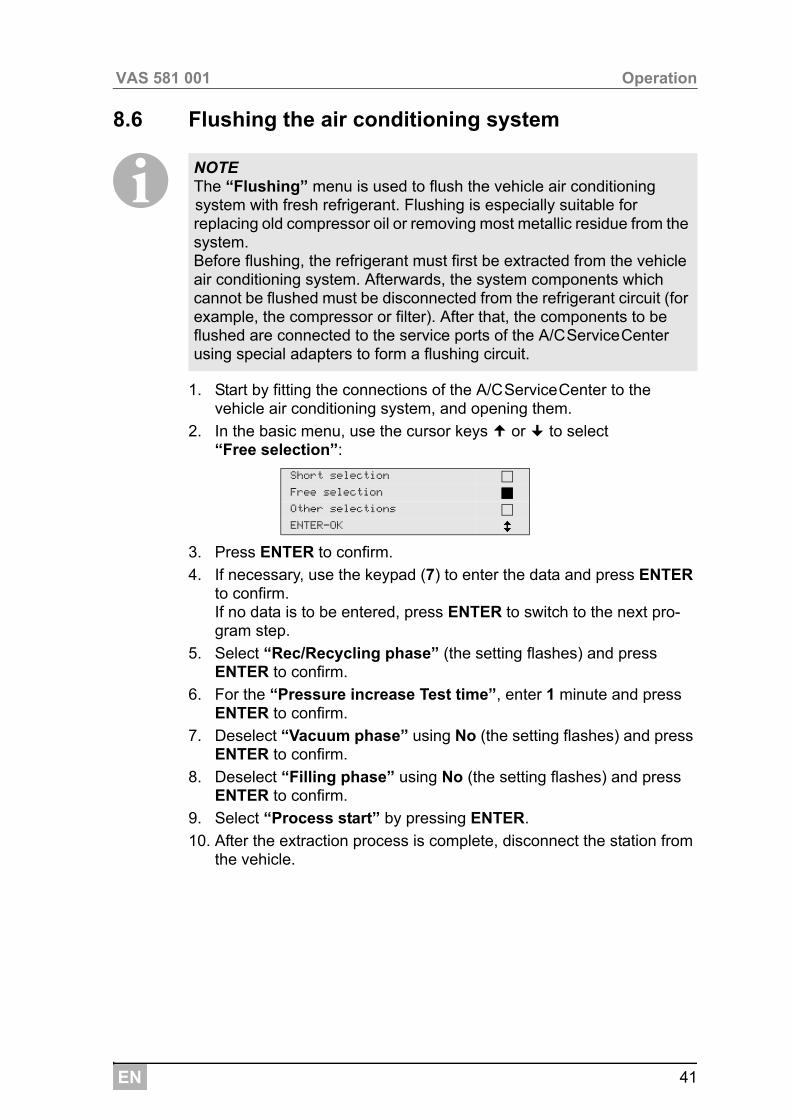
8.6 Flushing the air conditioning system
I
1. Start by fitting the connections of the A/CServiceCenter to the vehicle air conditioning system, and opening them.
2. In the basic menu, use the cursor keys or to select “Free selection”:
3. Press ENTER to confirm.
4. If necessary, use the keypad (7) to enter the data and press ENTER to confirm.If no data is to be entered, press ENTER to switch to the next pro-gram step.
5. Select “Rec/Recycling phase” (the setting flashes) and press ENTER to confirm.
6. For the “Pressure increase Test time”, enter 1 minute and press ENTER to confirm.
7. Deselect “Vacuum phase” using No (the setting flashes) and press ENTER to confirm.
8. Deselect “Filling phase” using No (the setting flashes) and press ENTER to confirm.
9. Select “Process start” by pressing ENTER.
10. After the extraction process is complete, disconnect the station from the vehicle.
NOTE The “Flushing” menu is used to flush the vehicle air conditioning system with fresh refrigerant. Flushing is especially suitable for replacing old compressor oil or removing most metallic residue from the system.Before flushing, the refrigerant must first be extracted from the vehicle air conditioning system. Afterwards, the system components which cannot be flushed must be disconnected from the refrigerant circuit (for example, the compressor or filter). After that, the components to be flushed are connected to the service ports of the A/CServiceCenter using special adapters to form a flushing circuit.
Short selection
Free selection
Other selections
ENTER-OK
EN
Operation VAS 581 001
42
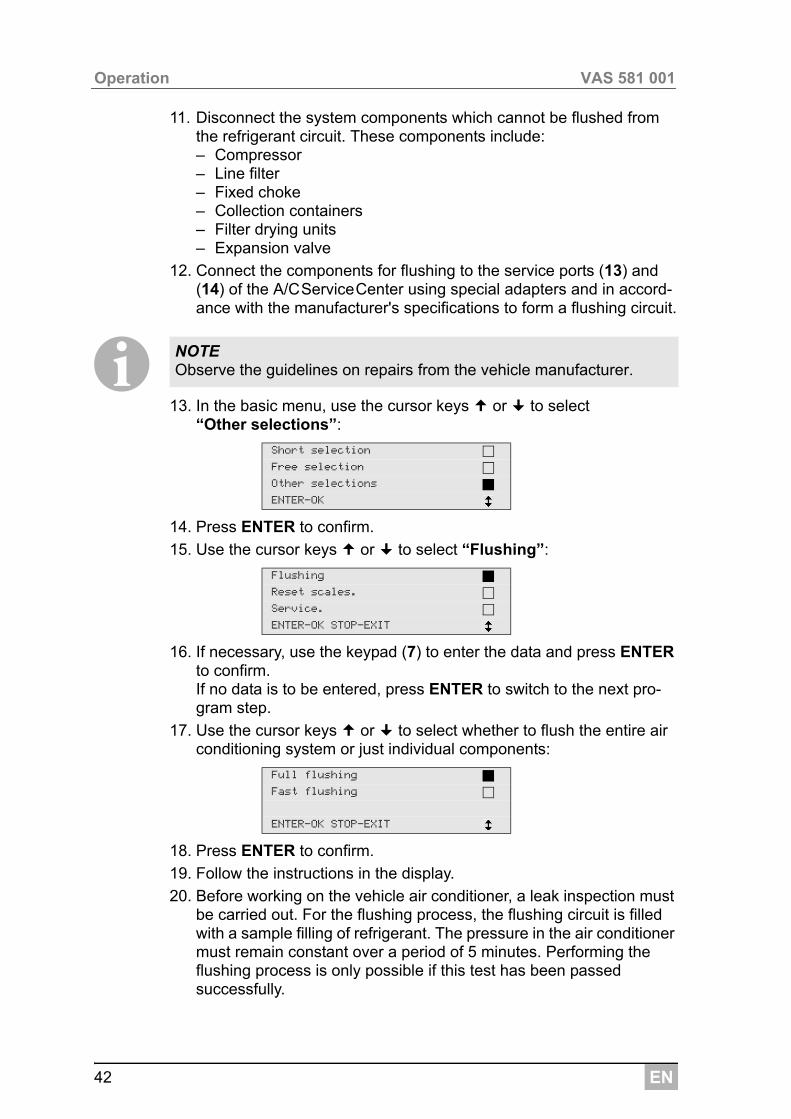
11. Disconnect the system components which cannot be flushed from the refrigerant circuit. These components include:– Compressor– Line filter– Fixed choke– Collection containers– Filter drying units– Expansion valve
12. Connect the components for flushing to the service ports (13) and (14) of the A/CServiceCenter using special adapters and in accord-ance with the manufacturer's specifications to form a flushing circuit.
I13. In the basic menu, use the cursor keys or to select
“Other selections”:
14. Press ENTER to confirm.
15. Use the cursor keys or to select “Flushing”:
16. If necessary, use the keypad (7) to enter the data and press ENTER to confirm.If no data is to be entered, press ENTER to switch to the next pro-gram step.
17. Use the cursor keys or to select whether to flush the entire air conditioning system or just individual components:
18. Press ENTER to confirm.
19. Follow the instructions in the display.
20. Before working on the vehicle air conditioner, a leak inspection must be carried out. For the flushing process, the flushing circuit is filled with a sample filling of refrigerant. The pressure in the air conditioner must remain constant over a period of 5 minutes. Performing the flushing process is only possible if this test has been passed successfully.
NOTE Observe the guidelines on repairs from the vehicle manufacturer.
Short selection
Free selection
Other selections
ENTER-OK
Flushing
Reset scales.
Service.
ENTER-OK STOP-EXIT
Full flushing
Fast flushing
ENTER-OK STOP-EXIT
EN 43
VAS 581 001 Operation
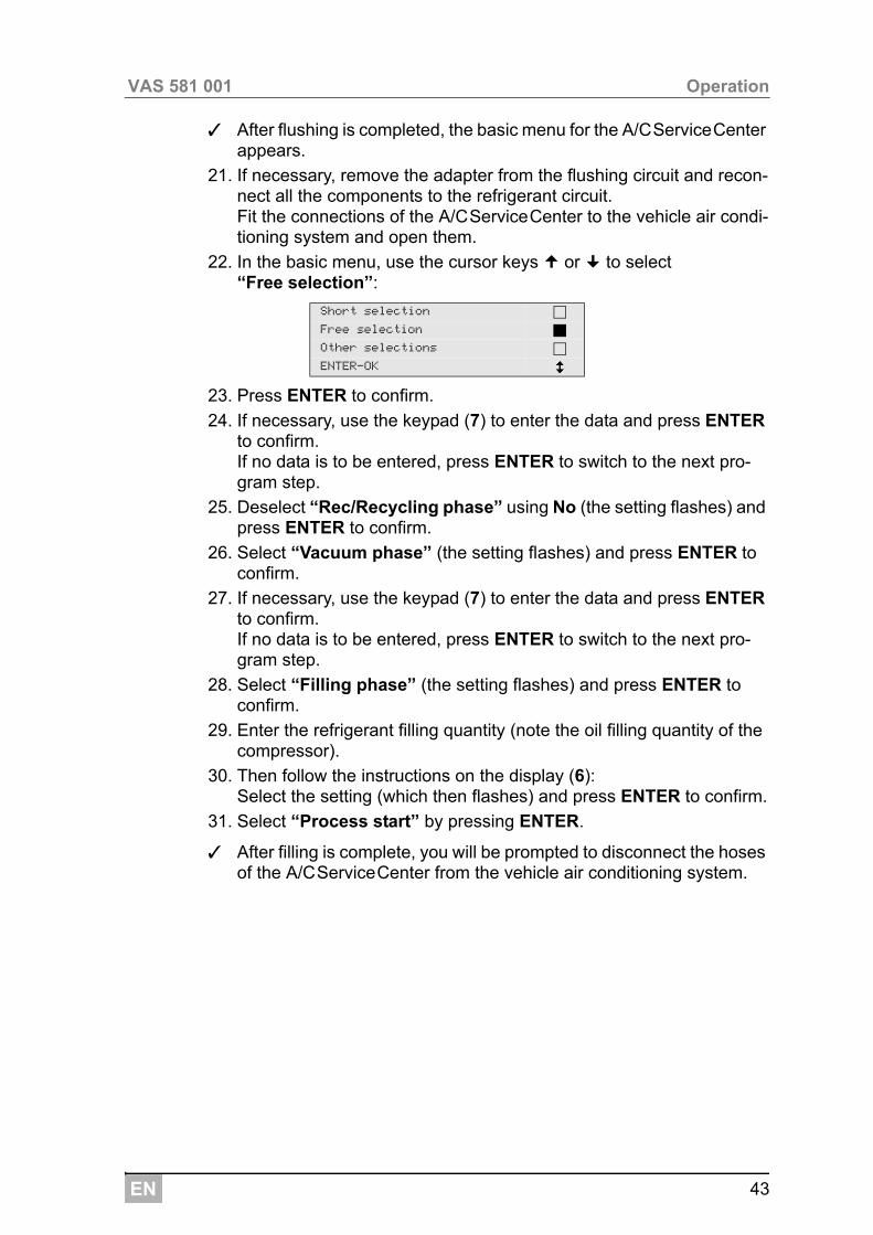
✓ After flushing is completed, the basic menu for the A/CServiceCenter appears.
21. If necessary, remove the adapter from the flushing circuit and recon-nect all the components to the refrigerant circuit. Fit the connections of the A/CServiceCenter to the vehicle air condi-tioning system and open them.
22. In the basic menu, use the cursor keys or to select “Free selection”:
23. Press ENTER to confirm.
24. If necessary, use the keypad (7) to enter the data and press ENTER to confirm.If no data is to be entered, press ENTER to switch to the next pro-gram step.
25. Deselect “Rec/Recycling phase” using No (the setting flashes) and press ENTER to confirm.
26. Select “Vacuum phase” (the setting flashes) and press ENTER to confirm.
27. If necessary, use the keypad (7) to enter the data and press ENTER to confirm.If no data is to be entered, press ENTER to switch to the next pro-gram step.
28. Select “Filling phase” (the setting flashes) and press ENTER to confirm.
29. Enter the refrigerant filling quantity (note the oil filling quantity of the compressor).
30. Then follow the instructions on the display (6):Select the setting (which then flashes) and press ENTER to confirm.
31. Select “Process start” by pressing ENTER.
✓ After filling is complete, you will be prompted to disconnect the hoses of the A/CServiceCenter from the vehicle air conditioning system.
Short selection
Free selection
Other selections
ENTER-OK
EN
Service tasks VAS 581 001
44
32. Disconnect the service hoses (11) and (12) and press ENTER to confirm. The service hoses will now be drained. The unit is then ready for further use.
33. Put the valve caps of the vehicle air conditioning system back on the connections.
9 Service tasks
9.1 Leak test
In addition to the internal leak test, perform a leak test in the A/CServiceCenter every six months with an electric leak detector.
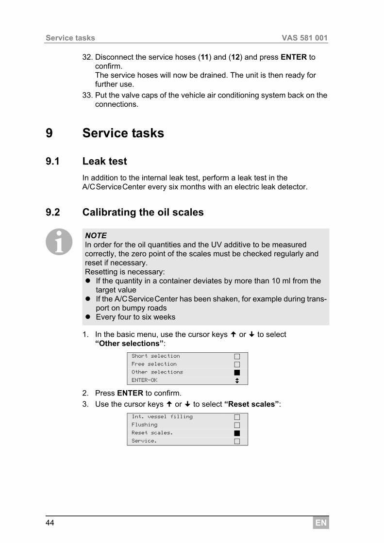
9.2 Calibrating the oil scales
I
1. In the basic menu, use the cursor keys or to select “Other selections”:
2. Press ENTER to confirm.
3. Use the cursor keys or to select “Reset scales”:
NOTE In order for the oil quantities and the UV additive to be measured correctly, the zero point of the scales must be checked regularly and reset if necessary. Resetting is necessary: If the quantity in a container deviates by more than 10 ml from the
target value If the A/CServiceCenter has been shaken, for example during trans-
port on bumpy roads Every four to six weeks
Short selection
Free selection
Other selections
ENTER-OK
Int. vessel filling
Flushing
Reset scales.
Service.
EN 45
VAS 581 001 Service tasks
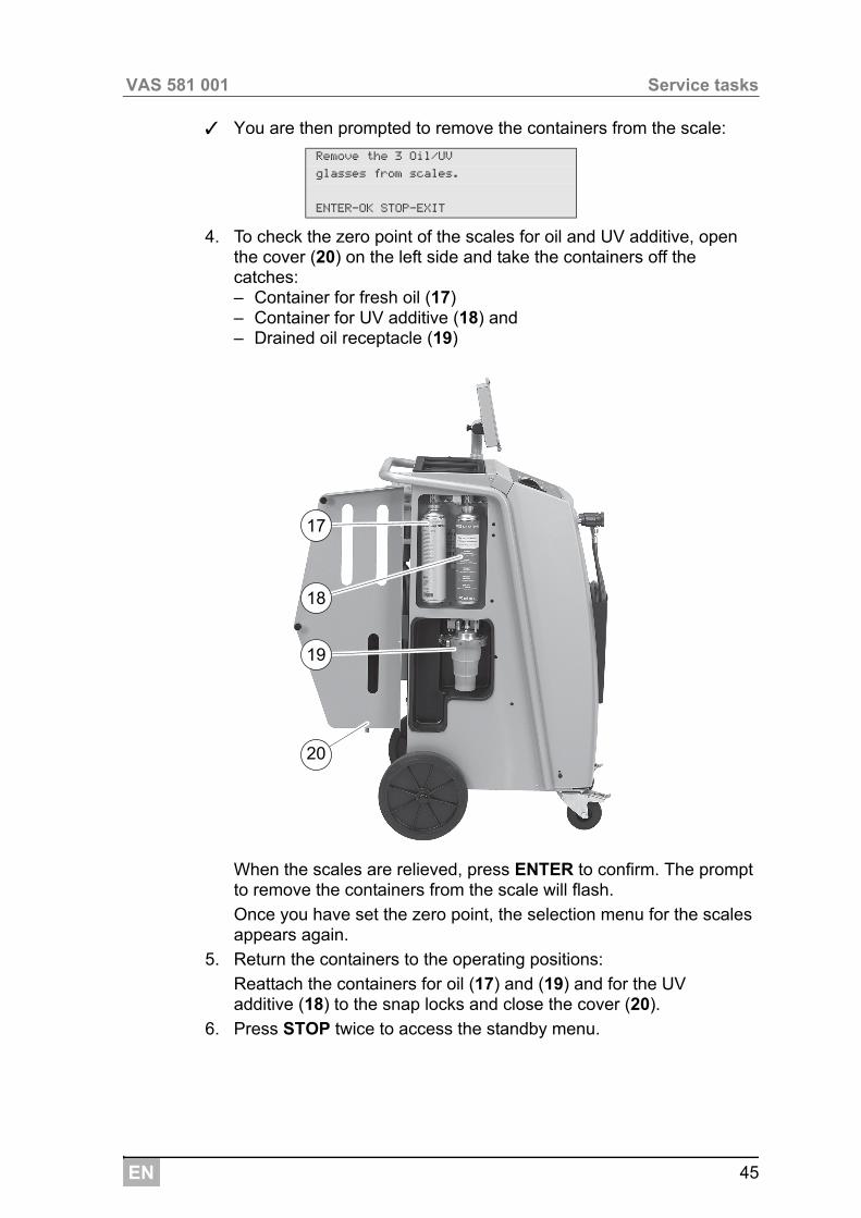
✓ You are then prompted to remove the containers from the scale:
4. To check the zero point of the scales for oil and UV additive, open the cover (20) on the left side and take the containers off the catches:– Container for fresh oil (17)– Container for UV additive (18) and– Drained oil receptacle (19)
When the scales are relieved, press ENTER to confirm. The prompt to remove the containers from the scale will flash.
Once you have set the zero point, the selection menu for the scales appears again.
5. Return the containers to the operating positions:
Reattach the containers for oil (17) and (19) and for the UV additive (18) to the snap locks and close the cover (20).
6. Press STOP twice to access the standby menu.
Remove the 3 Oil/UV
glasses from scales.
ENTER-OK STOP-EXIT
19
18
17
20
EN
Service tasks VAS 581 001
46
9.3 Changing the dryer filter
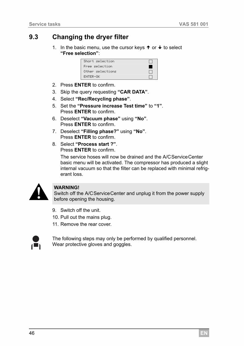
1. In the basic menu, use the cursor keys or to select “Free selection”:
2. Press ENTER to confirm.
3. Skip the query requesting “CAR DATA”.
4. Select “Rec/Recycling phase”.
5. Set the “Pressure increase Test time” to “1”. Press ENTER to confirm.
6. Deselect “Vacuum phase” using “No”. Press ENTER to confirm.
7. Deselect “Filling phase?” using “No”. Press ENTER to confirm.
8. Select “Process start ?”.Press ENTER to confirm.
The service hoses will now be drained and the A/CServiceCenter basic menu will be activated. The compressor has produced a slight internal vacuum so that the filter can be replaced with minimal refrig-erant loss.
!9. Switch off the unit.
10. Pull out the mains plug.
11. Remove the rear cover.
The following steps may only be performed by qualified personnel.Wear protective gloves and goggles.
Short selection
Free selection
Other selections
ENTER-OK
WARNING! Switch off the A/CServiceCenter and unplug it from the power supply before opening the housing.
EN 47
VAS 581 001 Service tasks
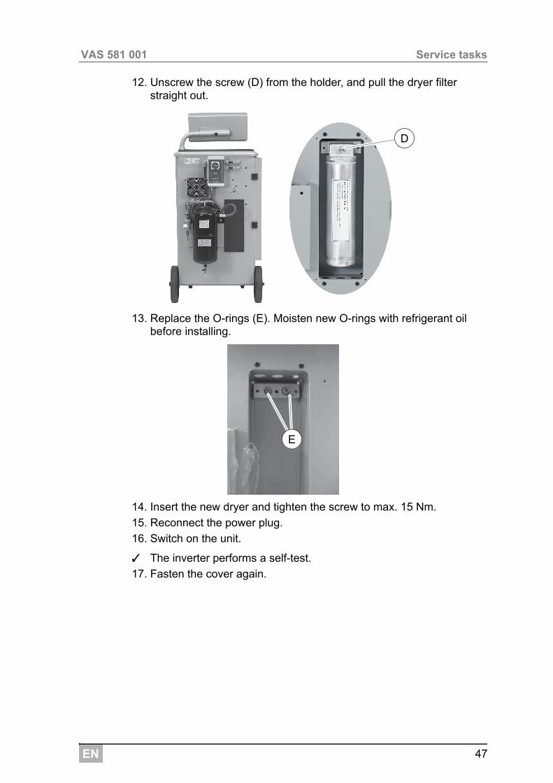
12. Unscrew the screw (D) from the holder, and pull the dryer filter straight out.
13. Replace the O-rings (E). Moisten new O-rings with refrigerant oil before installing.
14. Insert the new dryer and tighten the screw to max. 15 Nm.
15. Reconnect the power plug.
16. Switch on the unit.
✓ The inverter performs a self-test.
17. Fasten the cover again.
D
E
EN
Service tasks VAS 581 001
48
9.4 Filter maintenance
I
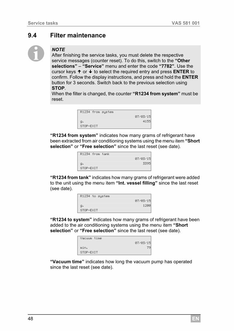
“R1234 from system” indicates how many grams of refrigerant have been extracted from air conditioning systems using the menu item “Short selection” or “Free selection” since the last reset (see date).
“R1234 from tank” indicates how many grams of refrigerant were added to the unit using the menu item “Int. vessel filling” since the last reset (see date).
“R1234 to system” indicates how many grams of refrigerant have been added to the air conditioning systems using the menu item “Short selection” or “Free selection” since the last reset (see date).
“Vacuum time” indicates how long the vacuum pump has operated since the last reset (see date).
NOTE After finishing the service tasks, you must delete the respective service messages (counter reset). To do this, switch to the “Other selections” – “Service” menu and enter the code “7782”. Use the cursor keys or to select the required entry and press ENTER to confirm. Follow the display instructions, and press and hold the ENTER button for 3 seconds. Switch back to the previous selection using STOP.When the filter is changed, the counter “R1234 from system” must be reset.
R1234 from system
07/03/15
g. 4155
STOP-EXIT
R1234 from tank
07/03/15
g. 3395
STOP-EXIT
R1234 to system
07/03/15
g. 1200
STOP-EXIT
Vacuum time
07/03/15
min. 79
STOP-EXIT
EN 49
VAS 581 001 Service tasks
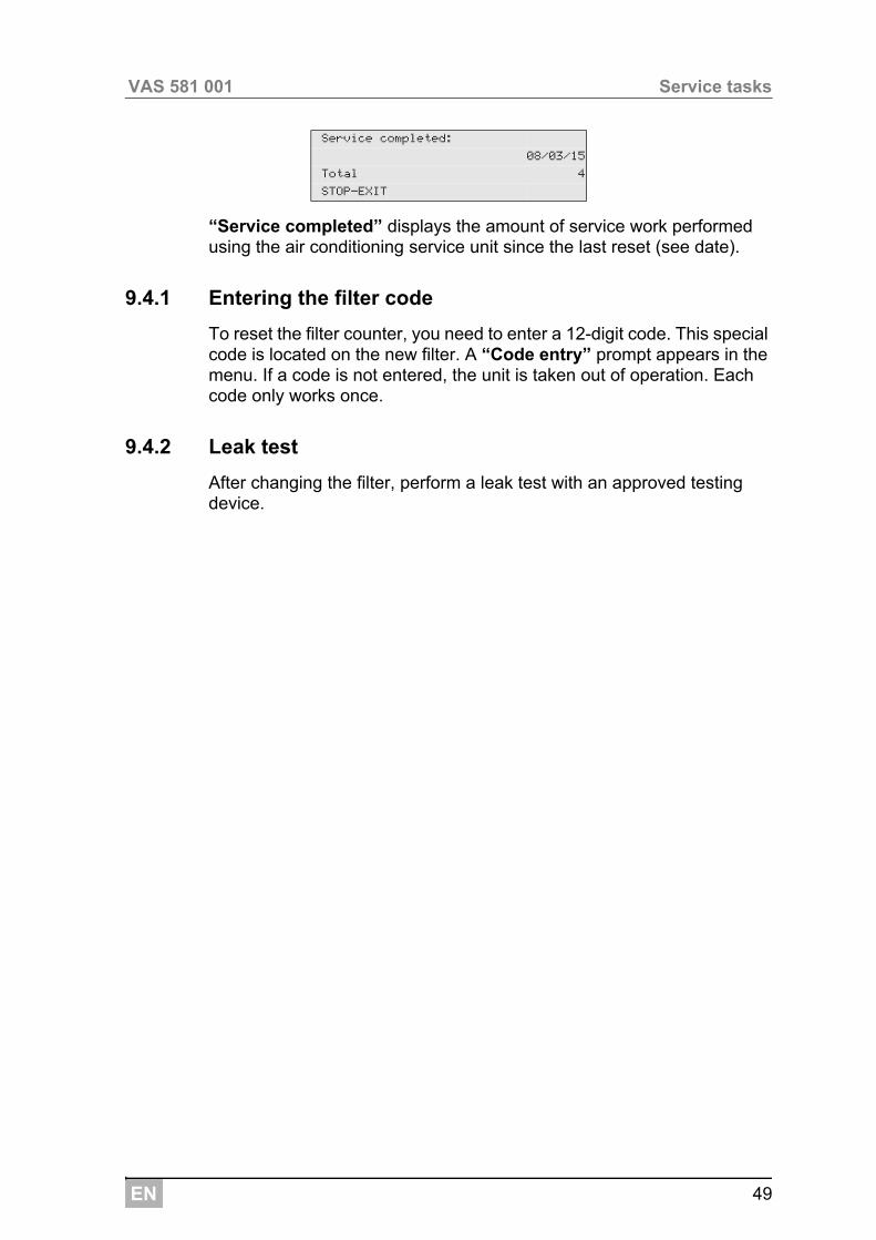
“Service completed” displays the amount of service work performed using the air conditioning service unit since the last reset (see date).
9.4.1 Entering the filter code
To reset the filter counter, you need to enter a 12-digit code. This special code is located on the new filter. A “Code entry” prompt appears in the menu. If a code is not entered, the unit is taken out of operation. Each code only works once.
9.4.2 Leak test
After changing the filter, perform a leak test with an approved testing device.
Service completed:
08/03/15
Total 4
STOP-EXIT
EN
Service tasks VAS 581 001
50
9.5 Calibrating the pressure transducer
I
1. In the basic menu, use the cursor keys or to select “Other selections”:
2. Depressurise the unit (as described in chapter “Changing the dryer filter” on page 46).
3. Press ENTER to confirm.
4. Use the cursor keys or to select “Service”:
5. Press ENTER to confirm.
6. Enter the password “2224”.
7. Confirm “Pressure transducer” by pressing ENTER.
8. Then follow the instructions in the display.– Unscrew the service couplings (13) and (14) from the service
hoses (11) and (12).– Use the keypad (7) to enter the current local atmospheric pressure
and press ENTER to confirm.
I9. When calibration has been completed, press ENTER to exit the
menu.
10. Press STOP twice to access the standby menu.
11. Screw the service couplings (13) and (14) hand-tight onto the service hoses (11) and (12), taking care not to mix up the red and blue mark-ings on the couplings and hoses.
NOTE The pressure transducer has to be correctly calibrated in order to make accurate pressure measurements.Calibration is required: Every four weeks If the A/CServiceCenter has been subjected to heavy shaking Every time the vacuum pump oil is changed If the display shows implausible pressure readings
Short selection
Free selection
Other selections
ENTER-OK
Int. vessel filling
Flushing
Reset scales.
Service.
NOTE You can look up the current atmospheric pressure for your region on the Internet, for example at http://www.meteo24.de/wetter/ under “air pres-sure”.
EN 51
VAS 581 001 Service tasks
9.6 Changing the vacuum pump oil
!1. Before changing the oil, let the vacuum pump run for about 10 min-
utes (manually, via the menu).
The following steps may only be performed by qualified personnel.
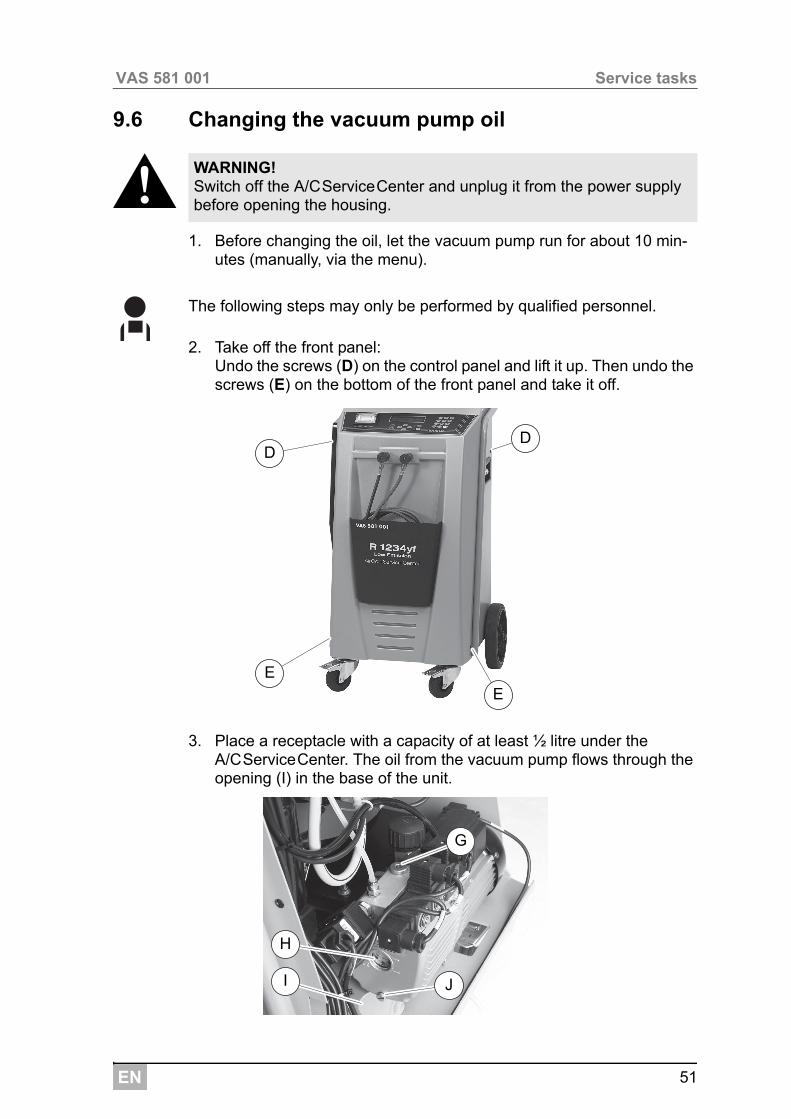
2. Take off the front panel: Undo the screws (D) on the control panel and lift it up. Then undo the screws (E) on the bottom of the front panel and take it off.
3. Place a receptacle with a capacity of at least ½ litre under the A/CServiceCenter. The oil from the vacuum pump flows through the opening (I) in the base of the unit.
WARNING! Switch off the A/CServiceCenter and unplug it from the power supply before opening the housing.
D
E
D
E
G
H
JI
EN
Service tasks VAS 581 001
52
4. Unscrew the oil filling plug (G).
5. To drain the oil, unscrew the oil drain plug (J).
6. Once the oil has been completely drained from the pump housing, screw the oil drain plug (J) back in.
7. Top up with new vacuum pump oil to the middle of the sight glass (H) and screw the oil filling plug (G) back in.
8. Put the front panel and control panel back on and reconnect the power plug.
INOTE After finishing the service tasks, you must delete the respective service messages (counter reset). To do this, switch to the “Other selections” – “Service” menu and enter the code “7782”. Use the cursor keys or to select the required entry and press ENTER to confirm. Follow the display instructions, and press and hold the ENTER button for 3 seconds. Switch back to the previous selection using STOP.When changing the vacuum pump oil, the counter “Vacuum time” must be reset.
EN 53
VAS 581 001 Service tasks
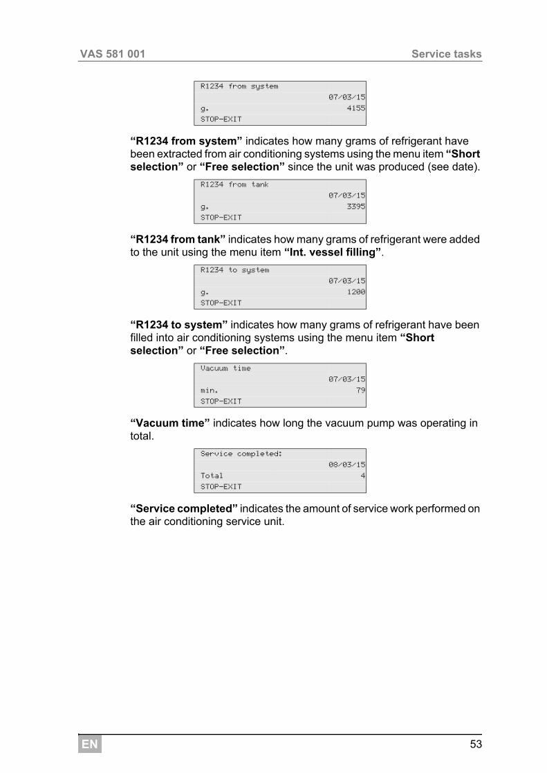
“R1234 from system” indicates how many grams of refrigerant have been extracted from air conditioning systems using the menu item “Short selection” or “Free selection” since the unit was produced (see date).
“R1234 from tank” indicates how many grams of refrigerant were added to the unit using the menu item “Int. vessel filling”.
“R1234 to system” indicates how many grams of refrigerant have been filled into air conditioning systems using the menu item “Short selection” or “Free selection”.
“Vacuum time” indicates how long the vacuum pump was operating in total.
“Service completed” indicates the amount of service work performed on the air conditioning service unit.
R1234 from system
07/03/15
g. 4155
STOP-EXIT
R1234 from tank
07/03/15
g. 3395
STOP-EXIT
R1234 to system
07/03/15
g. 1200
STOP-EXIT
Vacuum time
07/03/15
min. 79
STOP-EXIT
Service completed:
08/03/15
Total 4
STOP-EXIT
EN
Service tasks VAS 581 001
54
9.7 Meter readings
I
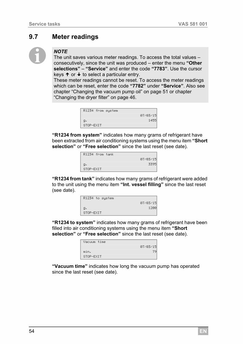
“R1234 from system” indicates how many grams of refrigerant have been extracted from air conditioning systems using the menu item “Short selection” or “Free selection” since the last reset (see date).
“R1234 from tank” indicates how many grams of refrigerant were added to the unit using the menu item “Int. vessel filling” since the last reset (see date).
“R1234 to system” indicates how many grams of refrigerant have been filled into air conditioning systems using the menu item “Short selection” or “Free selection” since the last reset (see date).
“Vacuum time” indicates how long the vacuum pump has operated since the last reset (see date).
NOTE The unit saves various meter readings. To access the total values – consecutively, since the unit was produced – enter the menu “Other selections” – “Service” and enter the code “7783”. Use the cursor keys or to select a particular entry.These meter readings cannot be reset. To access the meter readings which can be reset, enter the code “7782” under “Service”. Also see chapter “Changing the vacuum pump oil” on page 51 or chapter “Changing the dryer filter” on page 46.
R1234 from system
07/03/15
g. 1455
STOP-EXIT
R1234 from tank
07/03/15
g. 3395
STOP-EXIT
R1234 to system
07/03/15
g. 1200
STOP-EXIT
Vacuum time
07/03/15
min. 79
STOP-EXIT
EN 55
VAS 581 001 Service tasks
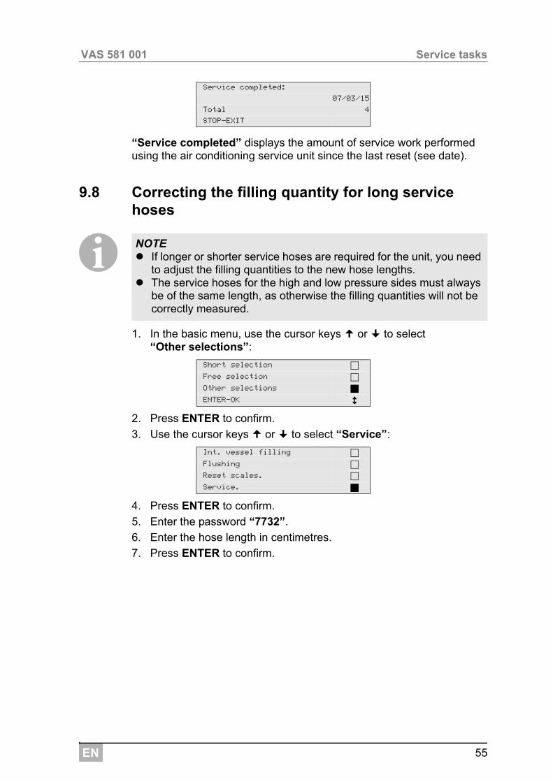
“Service completed” displays the amount of service work performed using the air conditioning service unit since the last reset (see date).
9.8 Correcting the filling quantity for long service hoses
I
1. In the basic menu, use the cursor keys or to select “Other selections”:
2. Press ENTER to confirm.
3. Use the cursor keys or to select “Service”:
4. Press ENTER to confirm.
5. Enter the password “7732”.
6. Enter the hose length in centimetres.
7. Press ENTER to confirm.
Service completed:
07/03/15
Total 4
STOP-EXIT
NOTE If longer or shorter service hoses are required for the unit, you need
to adjust the filling quantities to the new hose lengths. The service hoses for the high and low pressure sides must always
be of the same length, as otherwise the filling quantities will not be correctly measured.
Short selection
Free selection
Other selections
ENTER-OK
Int. vessel filling
Flushing
Reset scales.
Service.
EN
Service tasks VAS 581 001
56
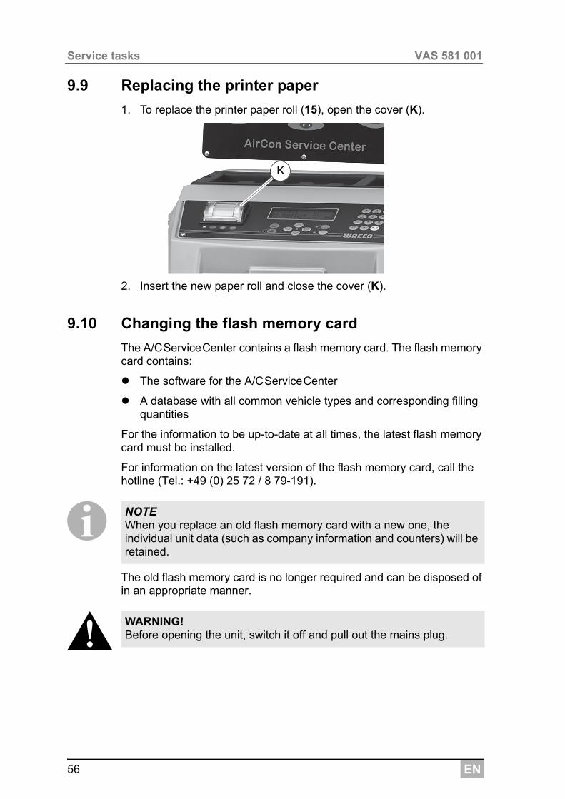
9.9 Replacing the printer paper
1. To replace the printer paper roll (15), open the cover (K).
2. Insert the new paper roll and close the cover (K).
9.10 Changing the flash memory card
The A/CServiceCenter contains a flash memory card. The flash memory card contains:
The software for the A/CServiceCenter
A database with all common vehicle types and corresponding filling quantities
For the information to be up-to-date at all times, the latest flash memory card must be installed.
For information on the latest version of the flash memory card, call the hotline (Tel.: +49 (0) 25 72 / 8 79-191).
IThe old flash memory card is no longer required and can be disposed of in an appropriate manner.
!
NOTE When you replace an old flash memory card with a new one, the individual unit data (such as company information and counters) will be retained.
WARNING! Before opening the unit, switch it off and pull out the mains plug.
K
EN 57
VAS 581 001 Service tasks
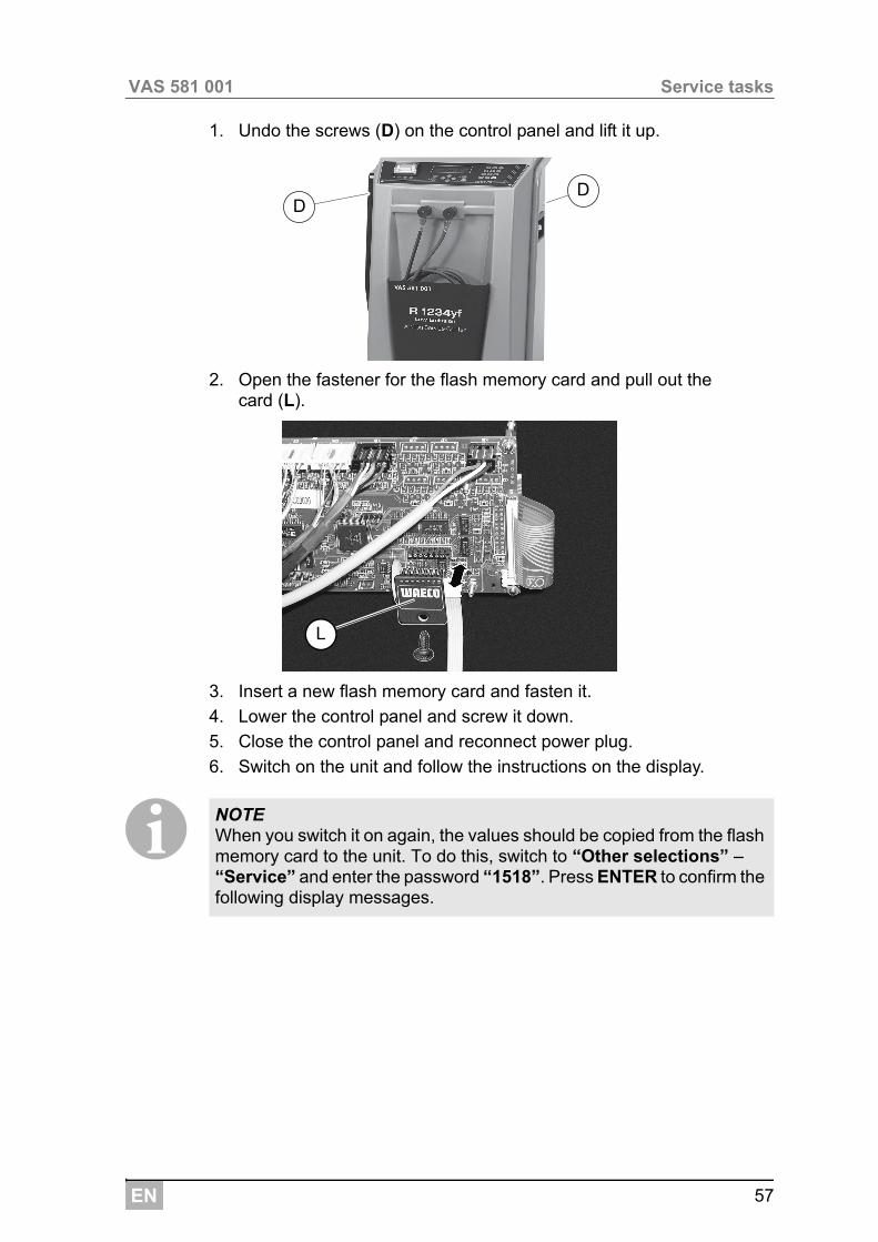
1. Undo the screws (D) on the control panel and lift it up.
2. Open the fastener for the flash memory card and pull out the card (L).
3. Insert a new flash memory card and fasten it.
4. Lower the control panel and screw it down.
5. Close the control panel and reconnect power plug.
6. Switch on the unit and follow the instructions on the display.
INOTE When you switch it on again, the values should be copied from the flash memory card to the unit. To do this, switch to “Other selections” – “Service” and enter the password “1518”. Press ENTER to confirm the following display messages.
DD
L
EN
Service tasks VAS 581 001
58
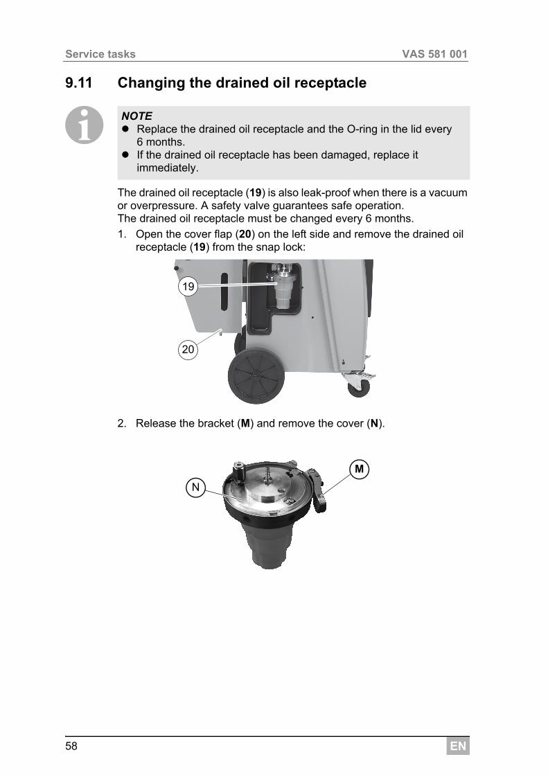
9.11 Changing the drained oil receptacle
IThe drained oil receptacle (19) is also leak-proof when there is a vacuum or overpressure. A safety valve guarantees safe operation.The drained oil receptacle must be changed every 6 months.
1. Open the cover flap (20) on the left side and remove the drained oil receptacle (19) from the snap lock:
2. Release the bracket (M) and remove the cover (N).
NOTE Replace the drained oil receptacle and the O-ring in the lid every
6 months. If the drained oil receptacle has been damaged, replace it
immediately.
19
20
M
N
EN 59
VAS 581 001 Service tasks
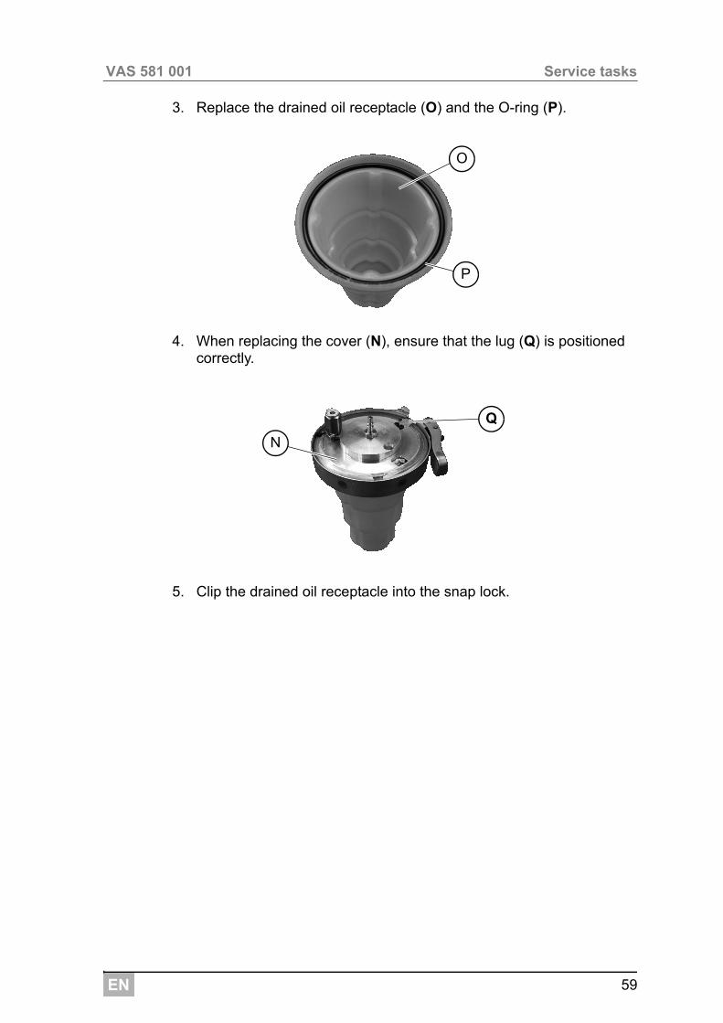
3. Replace the drained oil receptacle (O) and the O-ring (P).
4. When replacing the cover (N), ensure that the lug (Q) is positioned correctly.
5. Clip the drained oil receptacle into the snap lock.
O
P
Q
N
EN
Service tasks VAS 581 001
60
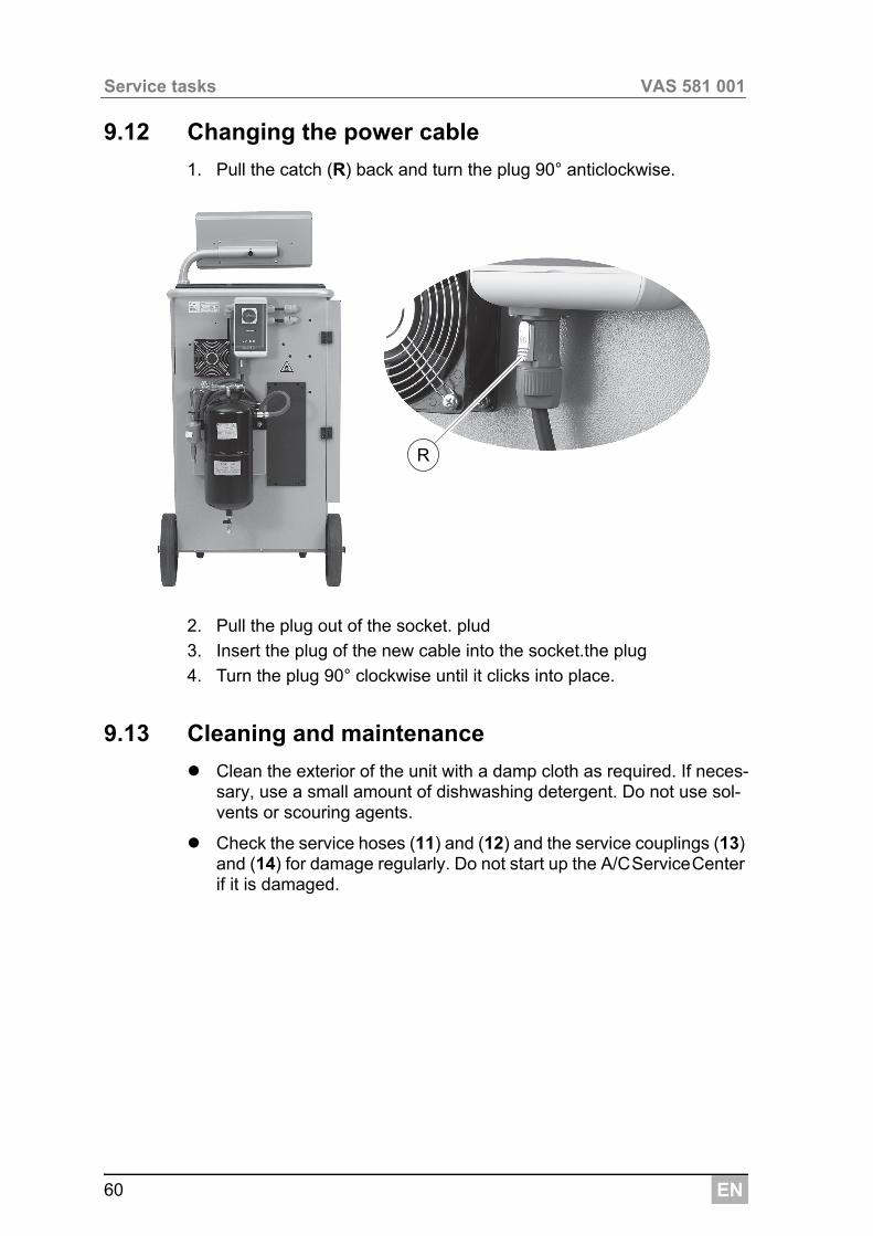
9.12 Changing the power cable
1. Pull the catch (R) back and turn the plug 90° anticlockwise.
2. Pull the plug out of the socket. plud
3. Insert the plug of the new cable into the socket.the plug
4. Turn the plug 90° clockwise until it clicks into place.
9.13 Cleaning and maintenance
Clean the exterior of the unit with a damp cloth as required. If neces-sary, use a small amount of dishwashing detergent. Do not use sol-vents or scouring agents.
Check the service hoses (11) and (12) and the service couplings (13) and (14) for damage regularly. Do not start up the A/CServiceCenter if it is damaged.
R
EN 61
VAS 581 001 Disposal
10 Disposal
10.1 Disposing of used fluids
I10.2 Disposing of packaging material
The cardboard packaging material should be disposed of with other waste paper.
Plastic packaging material should be added to other recyclable waste.
10.3 Scrapping the old unit
If you wish to scrap the A/CServiceCenter, first completely drain it of all liquids and dispose of them in an environmentally responsible manner.
M Take the old unit to your nearest recycling centre or contact the
customer service.
NOTE Used oil is hazardous waste.Do not mix used oil with other fluids.Keep used oil in suitable containers prior to disposal.
EN
Troubleshooting VAS 581 001
62
11 Troubleshooting
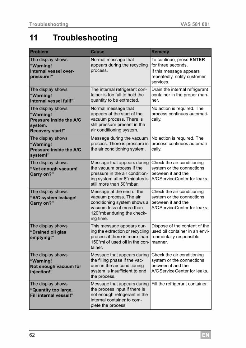
Problem Cause Remedy
The display shows“Warning! Internal vessel over-pressure!”
Normal message that appears during the recycling process.
To continue, press ENTER for three seconds.If this message appears repeatedly, notify customer services.
The display shows“Warning!Internal vessel full!”
The internal refrigerant con-tainer is too full to hold the quantity to be extracted.
Drain the internal refrigerant container in the proper man-ner.
The display shows“Warning! Pressure inside the A/C system.Recovery start!”
Normal message that appears at the start of the vacuum process. There is still pressure present in the air conditioning system.
No action is required. The process continues automati-cally.
The display shows“Warning! Pressure inside the A/C system!”
Message during the vacuum process. There is pressure in the air conditioning system.
No action is required. The process continues automati-cally.
The display shows“Not enough vacuum!Carry on?”
Message that appears during the vacuum process if the pressure in the air condition-ing system after 8°minutes is still more than 50°mbar.
Check the air conditioning system or the connections between it and the A/CServiceCenter for leaks.
The display shows“A/C system leakage!Carry on?”
Message at the end of the vacuum process. The air conditioning system shows a vacuum loss of more than 120°mbar during the check-ing time.
Check the air conditioning system or the connections between it and the A/CServiceCenter for leaks.
The display shows“Drained oil glas emptying!”
This message appears dur-ing the extraction or recycling process if there is more than 150°ml of used oil in the con-tainer.
Dispose of the content of the used oil container in an envi-ronmentally responsible manner.
The display shows“Warning!Not enough vacuum for injection!”
Message that appears during the filling phase if the vac-uum in the air conditioning system is insufficient to end the process.
Check the air conditioning system or the connections between it and the A/CServiceCenter for leaks.
The display shows“Quantity too large.Fill internal vessel!”
Message that appears during the process input if there is not enough refrigerant in the internal container to com-plete the process.
Fill the refrigerant container.
EN 63
VAS 581 001 Troubleshooting
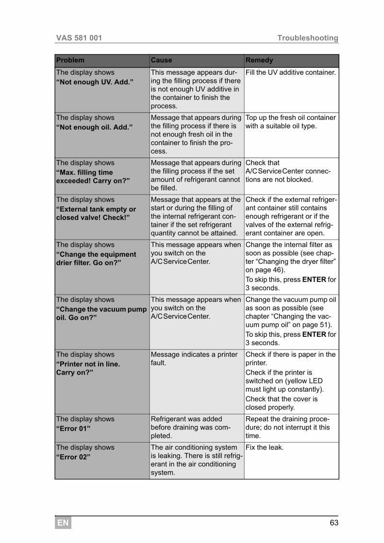
The display shows“Not enough UV. Add.”
This message appears dur-ing the filling process if there is not enough UV additive in the container to finish the process.
Fill the UV additive container.
The display shows“Not enough oil. Add.”
Message that appears during the filling process if there is not enough fresh oil in the container to finish the pro-cess.
Top up the fresh oil container with a suitable oil type.
The display shows“Max. filling time exceeded! Carry on?”
Message that appears during the filling process if the set amount of refrigerant cannot be filled.
Check that A/CServiceCenter connec-tions are not blocked.
The display shows“External tank empty or closed valve! Check!”
Message that appears at the start or during the filling of the internal refrigerant con-tainer if the set refrigerant quantity cannot be attained.
Check if the external refriger-ant container still contains enough refrigerant or if the valves of the external refrig-erant container are open.
The display shows“Change the equipment drier filter. Go on?”
This message appears when you switch on the A/CServiceCenter.
Change the internal filter as soon as possible (see chap-ter “Changing the dryer filter” on page 46).To skip this, press ENTER for 3 seconds.
The display shows“Change the vacuum pump oil. Go on?”
This message appears when you switch on the A/CServiceCenter.
Change the vacuum pump oil as soon as possible (see chapter “Changing the vac-uum pump oil” on page 51).To skip this, press ENTER for 3 seconds.
The display shows“Printer not in line. Carry on?”
Message indicates a printer fault.
Check if there is paper in the printer.Check if the printer is switched on (yellow LED must light up constantly).Check that the cover is closed properly.
The display shows“Error 01”
Refrigerant was added before draining was com-pleted.
Repeat the draining proce-dure; do not interrupt it this time.
The display shows“Error 02”
The air conditioning system is leaking. There is still refrig-erant in the air conditioning system.
Fix the leak.
Problem Cause Remedy
EN
Troubleshooting VAS 581 001
64
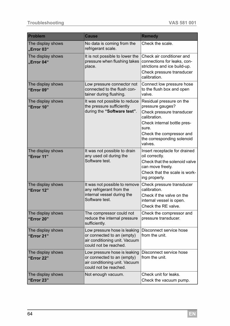
The display shows„Error 03“
No data is coming from the refrigerant scale.
Check the scale.
The display shows„Error 04“
It is not possible to lower the pressure when flushing takes place.
Check air conditioner and connections for leaks, con-strictions and ice build-up.Check pressure transducer calibration.
The display shows“Error 09”
Low pressure connector not connected to the flush con-tainer during flushing.
Connect low pressure hose to the flush box and open valve.
The display shows“Error 10”
It was not possible to reduce the pressure sufficiently during the “Software test”.
Residual pressure on the pressure gauges?Check pressure transducer calibration.Check internal bottle pres-sure.Check the compressor and the corresponding solenoid valves.
The display shows“Error 11”
It was not possible to drain any used oil during the Software test.
Insert receptacle for drained oil correctly.Check that the solenoid valve can move freely.Check that the scale is work-ing properly.
The display shows“Error 12”
It was not possible to remove any refrigerant from the internal vessel during the Software test.
Check pressure transducer calibration.Check if the valve on the internal vessel is open.Check the RE valve.
The display shows“Error 20”
The compressor could not reduce the internal pressure sufficiently.
Check the compressor and pressure transducer.
The display shows“Error 21”
Low pressure hose is leaking or connected to an (empty) air conditioning unit. Vacuum could not be reached.
Disconnect service hose from the unit.
The display shows“Error 22”
Low pressure hose is leaking or connected to an (empty) air conditioning unit. Vacuum could not be reached.
Disconnect service hose from the unit.
The display shows“Error 23”
Not enough vacuum. Check unit for leaks.Check the vacuum pump.
Problem Cause Remedy
EN 65
VAS 581 001 Troubleshooting
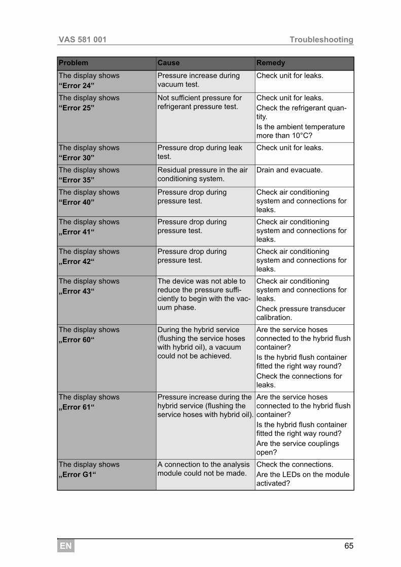
The display shows“Error 24”
Pressure increase during vacuum test.
Check unit for leaks.
The display shows“Error 25”
Not sufficient pressure for refrigerant pressure test.
Check unit for leaks.Check the refrigerant quan-tity.Is the ambient temperature more than 10°C?
The display shows“Error 30”
Pressure drop during leak test.
Check unit for leaks.
The display shows“Error 35”
Residual pressure in the air conditioning system.
Drain and evacuate.
The display shows“Error 40”
Pressure drop during pressure test.
Check air conditioning system and connections for leaks.
The display shows„Error 41“
Pressure drop during pressure test.
Check air conditioning system and connections for leaks.
The display shows„Error 42“
Pressure drop during pressure test.
Check air conditioning system and connections for leaks.
The display shows„Error 43“
The device was not able to reduce the pressure suffi-ciently to begin with the vac-uum phase.
Check air conditioning system and connections for leaks.Check pressure transducer calibration.
The display shows„Error 60“
During the hybrid service (flushing the service hoses with hybrid oil), a vacuum could not be achieved.
Are the service hoses connected to the hybrid flush container?Is the hybrid flush container fitted the right way round?Check the connections for leaks.
The display shows„Error 61“
Pressure increase during the hybrid service (flushing the service hoses with hybrid oil).
Are the service hoses connected to the hybrid flush container?Is the hybrid flush container fitted the right way round?Are the service couplings open?
The display shows„Error G1“
A connection to the analysis module could not be made.
Check the connections.Are the LEDs on the module activated?
Problem Cause Remedy
EN
Troubleshooting VAS 581 001
66
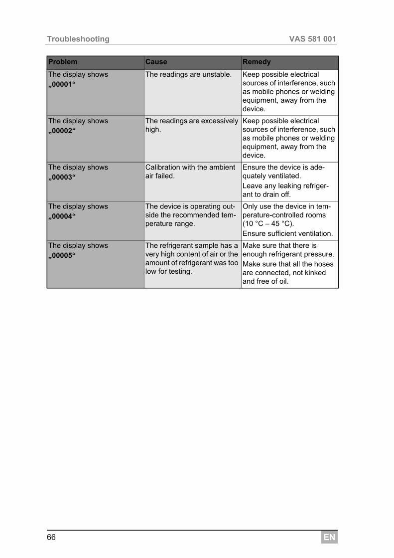
The display shows„00001“
The readings are unstable. Keep possible electrical sources of interference, such as mobile phones or welding equipment, away from the device.
The display shows„00002“
The readings are excessively high.
Keep possible electrical sources of interference, such as mobile phones or welding equipment, away from the device.
The display shows„00003“
Calibration with the ambient air failed.
Ensure the device is ade-quately ventilated.Leave any leaking refriger-ant to drain off.
The display shows„00004“
The device is operating out-side the recommended tem-perature range.
Only use the device in tem-perature-controlled rooms (10 °C – 45 °C).Ensure sufficient ventilation.
The display shows„00005“
The refrigerant sample has a very high content of air or the amount of refrigerant was too low for testing.
Make sure that there is enough refrigerant pressure.Make sure that all the hoses are connected, not kinked and free of oil.
Problem Cause Remedy
EN 67
VAS 581 001 Technical data
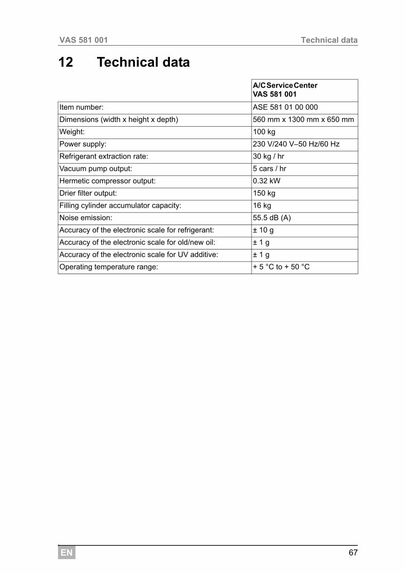
12 Technical data
A/CServiceCenter VAS 581 001
Item number: ASE 581 01 00 000
Dimensions (width x height x depth) 560 mm x 1300 mm x 650 mm
Weight: 100 kg
Power supply: 230 V/240 V–50 Hz/60 Hz
Refrigerant extraction rate: 30 kg / hr
Vacuum pump output: 5 cars / hr
Hermetic compressor output: 0.32 kW
Drier filter output: 150 kg
Filling cylinder accumulator capacity: 16 kg
Noise emission: 55.5 dB (A)
Accuracy of the electronic scale for refrigerant: ± 10 g
Accuracy of the electronic scale for old/new oil: ± 1 g
Accuracy of the electronic scale for UV additive: ± 1 g
Operating temperature range: + 5 °C to + 50 °C
AUSTRALIADometic Australia Pty. Ltd.1 John Duncan CourtVarsity Lakes QLD 4227 1800 212121 +61 7 55076001Mail: [email protected]
AUSTRIADometic Austria GmbHNeudorferstrasse 1082353 Guntramsdorf +43 2236 908070 +43 2236 90807060Mail: [email protected]
BENELUXDometic Benelux B.V.Ecustraat 3NL-4879 NP Etten-Leur +31 76 5029000 +31 76 5029090Mail: [email protected]
Dometic Branch Office BelgiumZinkstraat 13B-1500 Halle +32 2 3598040 +32 2 3598050Mail: [email protected]
BRAZILDometic DO Brasil LTDAAvenida Paulista 1754, conj. 151SP 01310-920 Sao Paulo +55 11 3251 3352 +55 11 3251 3362Mail: [email protected]
CHINAWAECO Impex Ltd.Shenzhen Futian office (WIE)1402-1404 1 D/F, Zhou Yue BuildningFu Hua Road, Futian Central Zone518048 Shenzhen +86 755 2560 7722
DENMARKDometic Denmark A/SNordensvej 15, TaulovDK-7000 Fredericia +45 75585966 +45 75586307Mail: [email protected]
FINLANDDometic Finland OYMestarintie 4FIN-01730 Vantaa +358 20 7413220 +358 9 7593700Mail: [email protected]
FRANCEDometic S.N.C.ZA du Pré de la Dame JeanneF-60128 Plailly +33 3 44633500 +33 3 44633518Commercial : [email protected]/Technique : [email protected]
HONG KONGWAECO Impex Ltd.Suites 2207-2211 · 22/F · Tower 1The Gateway · 25 Canton Road,Tsim Sha Tsui · Kowloon +852 24611386 +852 24665553Mail: [email protected]
ITALYDometic Italy S.r.l.Via Virgilio, 3I-47100 Forlì +39 0543 754901 +39 0543 756631Mail: [email protected]
MEXICODometic ABCircuito Médicos No. 6 Local 1Colonia Ciudad SatéliteCP 53100 Naucalpan de Juárez +52 55 5374 4108 +52 55 5374 4106 +52 55 5393 4683Mail: [email protected]
NORWAYDometic Norway ASSkolmar 24N-3232 Sandefjord +47 33428450 +47 33428459Mail: [email protected]
POLANDDometic Poland Sp. z o.o.Ul. Puławska 435A02-801 Warszawa +48 22 414 32 00 +48 22 414 32 01Mail: [email protected]
RUSSIADometic RUS LLCKomsomolskaya square 6-1107140 Moscow +7 495 780 79 39 +7 495 916 56 53Mail: [email protected]
SINGAPOREDometic Pte Ltd18 Boon Lay Way 06-140 Trade Hub 21Singapore 609966 +65 6795 3177 +65 6862 6620Mail: [email protected]
SLOVAKIADometic Slovakia Sales Office BratislavaNádražná 34/A900 28 Ivanka pri Dunaji +421 2 45 529 680 +421 2 45 529 680Mail: [email protected]
SOUTH AFRICADometic (Pty) Ltd. Regional OfficeSouth Africa & Sub-Saharan AfricaP. O. Box 25622008 Bedfordview +27 11 4504978 +27 82 4504976Mail: [email protected]
SPAINDometic Spain S.L.Avda. Sierra del Guadarrama, 16E-28691 Villanueva de la CañadaMadrid +34 902 111 042 +34 900 100 245Mail: [email protected]
SWEDENDometic Scandinavia ABGustaf Melins gata 7S-42131 Västra Frölunda (Göteborg) +46 31 7341100 +46 31 7341101Mail: [email protected]
SWITZERLANDDometic Switzerland AGRiedackerstrasse 7aCH-8153 Rümlang (Zürich) +41 44 8187171 +41 44 8187191Mail: [email protected]
UNITED ARAB EMIRATESDometic Middle East FZCOP. O. Box 17860S-D 6, Jebel Ali FreezoneDubai +971 4 883 3858 +971 4 883 3868Mail: [email protected]
UNITED KINGDOMDometic UK Ltd.Dometic House · The BreweryBlandford St. MaryDorset DT11 9LS +44 844 626 0133 +44 844 626 0143Mail: [email protected]
www.airconservice.de
GermanyDometic WAECO International GmbHHollefeldstraße 63D-48282 Emsdetten +49 (0) 2572 879-195 +49 (0) 2572 879-322Mail: [email protected]: www.dometic-waeco.de
4445
1013
34E
N10
/201
5