Embed Size (px)
Citation preview
8/3/2019 Acoustic Tamper Detection Sensor With Very Low False Alarm
http://slidepdf.com/reader/full/acoustic-tamper-detection-sensor-with-very-low-false-alarm 1/4
Acoustic Tamper Detection Sensor with Very LowFalse Alarm Rate
Lawrence Muijlwijk, and Jonathan ScottDepartment of Engineering, The University of Waikato
Private Bag 3105, Hamilton, 3240, New Zealand
Email: [email protected]
Abstract—We describe a device designed to detect interference(vandalism or tampering) by acoustic means. The design em-ploys both a piezoelectric vibration transducer and a commonmicrophone in a novel mechanical arrangement. In contrast toconventional acoustic sensors that simply respond to vibrationsabove a threshold, this design analyses the outputs of the two totrigger an alarm. The method confers a near-zero susceptibilityto triggering by external loud noises. No complex calculationsare required so that only a low-cost, embedded microcontrolleris required and the whole sensor can be very cheap. Extreme
sensitivity can be achieved with little risk of false alarms.
I. INTRODUCTION
Tamper detection systems based on acoustic vibration have
been used to detect interference with vehicles, fences, doors,
gates, and enclosures for many decades. [1], [2] A piezoelec-
tric transducer, alternately called a “shock sensor” or “reso-
nance microphone”, is often used to pick up the sound. The
main problem with this type of system is a high false alarm
rate. The basic system triggers when peak or averaged energy
exceeds a threshold, and external events can convey more
energy than some interference events, so that the selection
of the threshold level becomes a tradeoff between sensitivity
and susceptibility to false alarms. A well-known manifestationof this is car alarms going off because of a thunder clap or
similar loud noise. Various schemes have been employed over
the years to differentiate between geniune events and false
alarms, both analog and using considerable DSP capability.
[3]–[5] These transducers are now mostly confined to glass
breakage applications, where the intensity and spectrum of
the event makes it relatively easy to distinguish from ambient
sounds so that false alarms are minimised. [6], [7]
A number of schemes have appeared that effectively try
to minimise false alarms by dynamically adjusting the detec-
tion threshold, for example as a funcion of weather [8] or
sound measured elsewhere [9]. Our solution resembles these
approaches, but contains two transducers within a single smallunit.
I I . THE PROPOSED DESIGN
We note that a physical impact on the object to which a
sensor is attached tends to transfer a lot more energy to the
sensor as opposed to an ambient loud noise. This is because the
sound waves travel much more efficiently in a solid material.
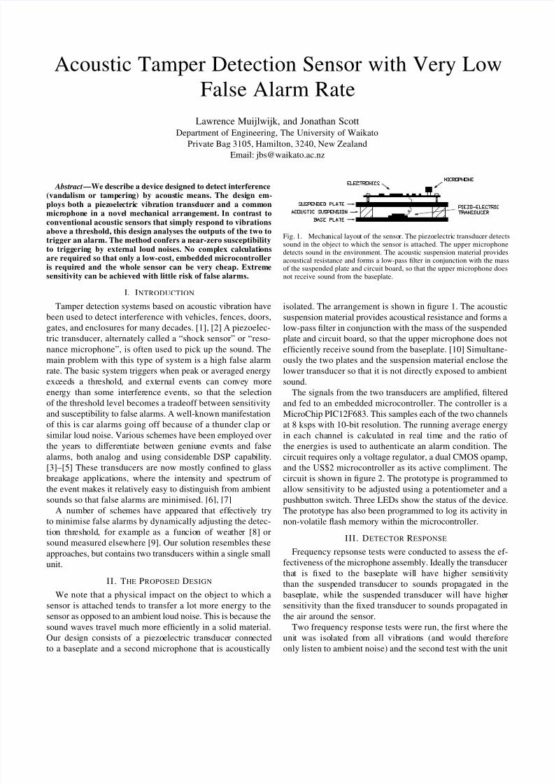
Our design consists of a piezoelectric transducer connected
to a baseplate and a second microphone that is acoustically
Fig. 1. Mechanical layout of the sensor. The piezoelectric transducer detectssound in the object to which the sensor is attached. The upper microphonedetects sound in the environment. The acoustic suspension material providesacoustical resistance and forms a low-pass filter in conjunction with the massof the suspended plate and circuit board, so that the upper microphone does
not receive sound from the baseplate.
isolated. The arrangement is shown in figure 1. The acoustic
suspension material provides acoustical resistance and forms a
low-pass filter in conjunction with the mass of the suspended
plate and circuit board, so that the upper microphone does not
efficiently receive sound from the baseplate. [10] Simultane-
ously the two plates and the suspension material enclose the
lower transducer so that it is not directly exposed to ambient
sound.
The signals from the two transducers are amplified, filtered
and fed to an embedded microcontroller. The controller is a
MicroChip PIC12F683. This samples each of the two channelsat 8 ksps with 10-bit resolution. The running average energy
in each channel is calculated in real time and the ratio of
the energies is used to authenticate an alarm condition. The
circuit requires only a voltage regulator, a dual CMOS opamp,
and the US$2 microcontroller as its active compliment. The
circuit is shown in figure 2. The prototype is programmed to
allow sensitivity to be adjusted using a potentiometer and a
pushbutton switch. Three LEDs show the status of the device.
The prototype has also been programmed to log its activity in
non-volatile flash memory within the microcontroller.
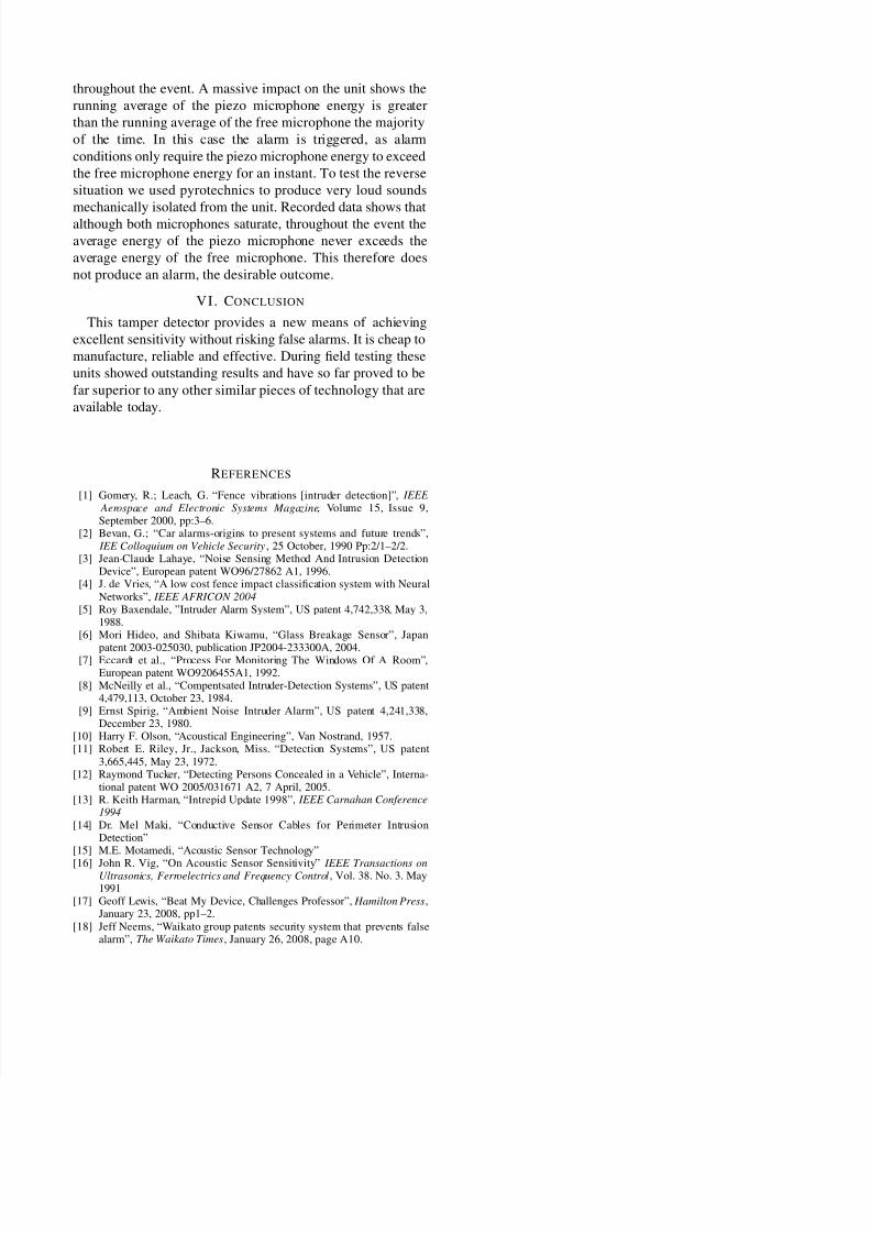
III. DETECTOR RESPONSE
Frequency repsonse tests were conducted to assess the ef-fectiveness of the microphone assembly. Ideally the transducer
that is fixed to the baseplate will have higher sensitivity
than the suspended transducer to sounds propagated in the
baseplate, while the suspended transducer will have higher
sensitivity than the fixed transducer to sounds propagated in
the air around the sensor.
Two frequency response tests were run, the first where the
unit was isolated from all vibrations (and would therefore
only listen to ambient noise) and the second test with the unit
8/3/2019 Acoustic Tamper Detection Sensor With Very Low False Alarm
http://slidepdf.com/reader/full/acoustic-tamper-detection-sensor-with-very-low-false-alarm 2/4
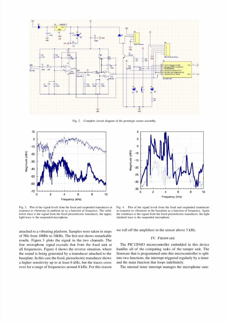
Fig. 2. Complete circuit diagram of the prototype sensor assembly.
Fig. 3. Plot of the signal levels from the fixed and suspended transducers inresponse to vibrations in ambient air as a function of frequency. The solid,lower trace is the signal from the fixed piezoelectric transducer, the upper,light trace is the suspended microphone.
attached to a vibrating platform. Samples were taken in steps
of 5Hz from 100Hz to 10kHz. The first test shows remarkable
results. Figure 3 plots the signal in the two channels. The
free microphone signal exceeds that from the fixed unit at
all frequencies. Figure 4 shows the reverse situation, where
the sound is being generated by a transducer attached to the
baseplate. In this case the fixed, piezoelectric transducer shows
a higher sensitivity up to at least 6 kHz, but the traces cross
over for a range of frequencies around 8 kHz. For this reason
Fig. 4. Plot of the signal levels from the fixed and suspended transducersin response to vibrations in the baseplate as a function of frequency. Againthe solidtrace is the signal from the fixed piezoelectric transducer, the light(dashed) trace is the suspended microphone.
we roll off the amplifiers in the sensor above 3 kHz.
IV. FIRMWARE
The PIC12F683 microcontroller embedded in this device
handles all of the computing tasks of the tamper unit. The
firmware that is programmed onto this microcontroller is split
into two functions, the interrupt triggered regularly by a timer
and the main function that loops indefinitely.
The internal timer interrupt manages the microphone sam-

8/3/2019 Acoustic Tamper Detection Sensor With Very Low False Alarm
http://slidepdf.com/reader/full/acoustic-tamper-detection-sensor-with-very-low-false-alarm 3/4
pling, alarm decisions and pushbutton routine. Figure 5 shows
a simplified flow chart of the internal timer interrupt.
The first step is to sample each of the microphones. This
is performed with the built in analogue to digital converter
in the microchip. A computationally cheap running average
of the energy of each microphone is then computed and
compared to operator defined thresholds. If the alarm con-
ditions are met then an alarm flag is triggered, that is; the
Piezo Microphone energy is greater than the Piezo threshold
AND the Piezo Microphone energy is x (operater defined)
times the Free Microphone energy. In reality these steps
are performed slighly out of synchronisation to maximise
efficiency through performing operations while the analogue
to digital convertor settles. This allows an 8kHz sample rate
in each channel running at 4 MIPS on the microcontroller’s
internally-generated clock.
The pushbutton routine that enables an operator to set
threshold values is also controlled within this interrupt. When
pushbutton activity is detected we can temporarily disregard
any alarm activity as this means there is currently an operator
present at the unit.The main loop simply performs the statistical logging and
alarm handling functions. On detection of the alarm trigger
flag the relay and LED are turned on.
In adition to the main workings of the unit, the prototype
units have had statistical logging functions included in their
firmware. Statitics such as piezo microphone events, micro-
phone saturations, alarms, number of powerups and seconds
of power applied are updated every 15 seconds while not
currently in an event. A tally of alarms per quarter hour is
also logged so data can be better analysed. These statistics are
all stored in the non-volatile flash memory in the PIC12F683
chip.
In order to ensure a quick enough microphone sampling ratein order that no events are missed, the timer interrupt is called
every 128 µs. The interupt function takes 90 µs to complete,
meaning the program is interrupt dominated, and is only in
the main loop for 30 percent of the time. However, this is not
a problem as none of the vital operations are performed in the
main loop, as explained above.
V. FIELD TESTS
To determine how the units would function in the field
several prototypes were deployed at various locations includ-
ing bus shelters, road signs, roading barriers, doors, vending
machines and a chain link fence. These locations involved a
large variation of human activity. During the field testing, asmall coin (weight 3.30 grams, slightly heavier than a US
penny) was dropped from measured heights onto the object
being monitored in order to measure sensitivity.
In the case of the steel roading barrier unit, the device was
set as sensitive as possible (a drop of less than half an inch
or ≈1 cm with the coin would set it off). This was sensitive
enough so that without the inhibition process a passing vehicle
would set the alarm off. However with the test units deployed
no alarms were reported, despite this extreme sensitivity.
Fig. 5. A simplified flow chart of the timer interrupt used in the tamperingdetector.
An experiment was conducted with one of the bus shelter
units. This unit was attached to the steel bench seat of the
bus shelter and was set intially with a low enough sensitivity
so without the inhibit process employed by our sensor, one
would not expect to observe false alarms. This corresponded
to a sensitivity that required roughly a 5 inch (13 cm) drop with
the coin for an alarm. After two days in the field the statistics
reported zero alarms. The same unit was then reinstalled with
maximum sensitivity (< 0.5 inch or ≈1 cm coin drop). After
two days the unit reported several alarms. This proved that
it could pick up events (with an almost zero false alarm
rate) where a similar unit without inhibition properties would
produce numerous false alarms.
A unit was deployed on a chain link fence as part of achallenge that could be attempted by the general public [17],
[18]. The fence was located in a public place where anybody
could access it. This was a two part challenge—the first part
being a prize for anyone who could successfully climb the
fence without triggering an alarm. The second part of the
challenge involved a more substantial prize for anyone who
could set off the alarm without any physical impact on the
fence (e.g. by means of loud noise, shaking the ground, etc).
Despite the challenge running for several weeks(??), no
prizes were awarded. Climbing the fence proved to be ex-
tremely difficult due to the high sensitivity that could be
achieved on the unit. Ultimately nobody was confident enough
that they would be able to perform the task infront of anofficial in order to claim the prize. Triggering an alarm without
touching the fence was also never achieved despite numerous
attempts.
As a supplement to this challenge, loud noise tests were
performed. The object of these tests were to saturate (overload)
both microphones by a considerable amount and see how the
unit behaved. The results showed that despite both micro-
phones saturating their respective op-amps, the sensor behaves
well. One channel registers more average energy than the other
8/3/2019 Acoustic Tamper Detection Sensor With Very Low False Alarm
http://slidepdf.com/reader/full/acoustic-tamper-detection-sensor-with-very-low-false-alarm 4/4
throughout the event. A massive impact on the unit shows the
running average of the piezo microphone energy is greater
than the running average of the free microphone the majority
of the time. In this case the alarm is triggered, as alarm
conditions only require the piezo microphone energy to exceed
the free microphone energy for an instant. To test the reverse
situation we used pyrotechnics to produce very loud sounds
mechanically isolated from the unit. Recorded data shows that
although both microphones saturate, throughout the event the
average energy of the piezo microphone never exceeds the
average energy of the free microphone. This therefore does
not produce an alarm, the desirable outcome.
VI . CONCLUSION
This tamper detector provides a new means of achieving
excellent sensitivity without risking false alarms. It is cheap to
manufacture, reliable and effective. During field testing these
units showed outstanding results and have so far proved to be
far superior to any other similar pieces of technology that are
available today.
REFERENCES
[1] Gomery, R.; Leach, G. “Fence vibrations [intruder detection]”, IEEE
Aerospace and Electronic Systems Magazine, Volume 15, Issue 9,September 2000, pp:3–6.
[2] Bevan, G.; “Car alarms-origins to present systems and future trends”, IEE Colloquium on Vehicle Security, 25 October, 1990 Pp:2/1–2/2.
[3] Jean-Claude Lahaye, “Noise Sensing Method And Intrusion DetectionDevice”, European patent WO96/27862 A1, 1996.
[4] J. de Vries, “A low cost fence impact classification system with NeuralNetworks”, IEEE AFRICON 2004
[5] Roy Baxendale, ”Intruder Alarm System”, US patent 4,742,338, May 3,1988.
[6] Mori Hideo, and Shibata Kiwamu, “Glass Breakage Sensor”, Japan
patent 2003-025030, publication JP2004-233300A, 2004.[7] Eccardt et al., “Process For Monitoring The Windows Of A Room”,
European patent WO9206455A1, 1992.[8] McNeilly et al., “Compentsated Intruder-Detection Systems”, US patent
4,479,113, October 23, 1984.[9] Ernst Spirig, “Ambient Noise Intruder Alarm”, US patent 4,241,338,
December 23, 1980.[10] Harry F. Olson, “Acoustical Engineering”, Van Nostrand, 1957.[11] Robert E. Riley, Jr., Jackson, Miss. “Detection Systems”, US patent
3,665,445, May 23, 1972.[12] Raymond Tucker, “Detecting Persons Concealed in a Vehicle”, Interna-
tional patent WO 2005/031671 A2, 7 April, 2005.[13] R. Keith Harman, “Intrepid Update 1998”, IEEE Carnahan Conference
1994[14] Dr. Mel Maki, “Conductive Sensor Cables for Perimeter Intrusion
Detection”[15] M.E. Motamedi, “Acoustic Sensor Technology”
[16] John R. Vig, “On Acoustic Sensor Sensitivity” IEEE Transactions onUltrasonics, Ferroelectrics and Frequency Control, Vol. 38. No. 3. May1991
[17] Geoff Lewis, “Beat My Device, Challenges Professor”, Hamilton Press,January 23, 2008, pp1–2.
[18] Jeff Neems, “Waikato group patents security system that prevents falsealarm”, The Waikato Times, January 26, 2008, page A10.