Embed Size (px)
Citation preview

FREEDOM® DISC COUPLINGSA new degree of freedom from maintenance

FALK FREEDOM® DISC COUPLINGSFreedom from buckling and fretting corrosion
FD06A10
As the recognized innovator in coupling design, Falk now takes overall“no-lube” coupling value to a new level with the latest Freedom FDG &FDP Disc Couplings.
Freedom FDG & FDP design advancements prevent buckling underload and eliminate fretting corrosion, setting new standards for “no-lube” coupling longevity and reliability. It’s a new degree of freedomfrom maintenance available exclusively from Falk.
Lower maintenanceFreedom Disc Couplings have nomoving parts, so there is no needfor lubrication. They are unaffectedby extreme temperature andmoisture. Plus, they can be visuallyinspected and discpacks replacedwithout moving connectedequipment.
No EnvironmentalLimitationsDisc couplings aren’t limited by theoperating range of greases. There isnothing to leak or becomecontaminated. Ozone, sunlight, ormoisture do not affect it’s lifespan.Disc couplings are not sensitive totemperature variations.
High Operating SpeedsBody-bound drive bolts and preci-sion registration give Disc couplingssuperior balance qualities to minimize vibrations for smooth running and optimum equipmentlife.
Precision SynchronizationDisc couplings do not have back-lash and do not wind-up torsionallyunder varying loading conditionsmaking them the ideal choice forprinting presses or machine toolswhere exact timing is required.Since they do not create torque ripples, they allow for a uniformthickness or gauge of productssuch as paper, plastics, glass, film,and sheet steel.
Long LifeIf you want to save parts, labor,inventory, and downtime try FalkFreedom Disc couplings. The flex-ing member in a Disc coupling is ofan all-steel construction, with excellent fatique properties. In fact,a properly selected and alignedcoupling may never need replacement parts.
FDG31AA SPACER DESIGN

FDG GeneralPurpose DesignsFalk FDG couplings utilize a single,thick 301 stainless steel disc toeliminate buckling in the compres-sive leg under load. This results inmore uniform stress distribution andlonger life. The load-carrying dischas been shot-peened for addedfatigue strength and has a scallopedoutside diameter for stress reductionand flexibility. The single disc elimi-nates rubbing contact and resultingfretting corrosion since there is onlyone blade. This design is the mosteconomical selection for general-purpose industrial applica-tions up to 12,390 lb.-in. of torque and shaft sizes up to 3.625”.
FDP HighPerformance DesignsThe FDP Series of couplings offersincreased torque capacities. It usesthe same hubs and spacercomponents as the FDG Series witha supercharged unitized discpackconsisting of several, thick 301stainless scalloped steel discs thathave been shot-peened foradditional fatigue strength. Theindividual discs are separated bythin washers to eliminate the disccontact that can result in frettingcorrosion in conventional discpacks.
FDP couplings are available to torque capacities of
153,000 lb.-in. and 6.875” bore
capacity.
FD06A10 SPACER DESIGN
Improved FastenersTo further reduce maintenanceneeds, the drive bolts for the FDG& FDP are coated with Dacromet®.This exceptional quality coatingdelivers 4-way corrosion resistance,including self-repairing properties.Any way you look at it, this cou-pling redefines freedom from main-tenance. Freedom Disc Couplings...one more reason you can’t affordnot to use Falk.
Dacromet propertiesSalt spray performance: 500 hrs minimum
Heat resistance: 550° F (287° C) to 650°
F (343° C)
Coating thickness: 0.2-0.3 mils
FD DesignsFalk’s original spacer couplingdesign provides still higher torqueand bore capacities for heavy-dutyapplications. This design uses manythin discs in unitized packs to providegenerous misalignment capacity andhigh torque ratings. FD designs areavailable up to 2,772,000 lb.-in.torque and bores up to 15.75”.

Spacer CouplingsFDG & FDP Series couplings featurea 3-piece spacer spool design. Theheavy walled spacer tube is regis-tered to the flanges. The assemblymeets AGMA 9000 Balance Class 9and allows for manufacturingversatility to produce any lengthspacer (within catalog limits) whilemaintaining short lead times.
Type 31 spacer designs includeanti-fly adapters as a standardfeature to meet API specifications.This feature prevents the spacerassembly from being thrown in theevent of a catastrophic failure of thediscs and bolts.
Close-Connected CouplingsFalk close-connected couplingsfeature a split spacer spool to allowfor the removal and replacement ofthe disc or discpack without theneed to move connected equip-ment. The short gaps of thesecouplings allow them to be used inplace of common gear and gridcouplings as well as other close-connect disc designs.
FDG10CC CLOSE COUPLED
FDG31AA SPACER DESIGN
FD06A10 SPACER DESIGN
Freedom Disc Coupling Product Types

Table of ContentsAvailable Designs . . . . . . . . . . . . . . . . . . . . . . 6
How to Select . . . . . . . . . . . . . . . . . . . . . . . . 7
Quick Selection Method . . . . . . . . . . . . . . . . . 8 & 9
Service Factors . . . . . . . . . . . . . . . . . . . . . . . 10
How to Order . . . . . . . . . . . . . . . . . . . . . . . 11
Dimensions & Specifications
Series FDG
Nomenclature . . . . . . . . . . . . . . . . . . . . . . . 12
Type FDG10CC, 11CC & 12CC . . . . . . . . . . . . . . 13
Type FDG10DD, 11DD & 12DD. . . . . . . . . . . . . . . 14
Type FDG30NN . . . . . . . . . . . . . . . . . . . . . . 15
Type FDG31AA, AL, LL . . . . . . . . . . . . . . . . . . . 16
Type FDG20NN . . . . . . . . . . . . . . . . . . . . . . 17
Type FDG20AN . . . . . . . . . . . . . . . . . . . . . . 18
Type FDG50NN, 55NN. . . . . . . . . . . . . . . . . . . 19
Type FDG50AA, 55AA . . . . . . . . . . . . . . . . . . . 20
Series FDP
Nomenclature . . . . . . . . . . . . . . . . . . . . . . . 21
Type FDP10CC, 11CC & 12CC . . . . . . . . . . . . . . . 22
Type FDP30NN . . . . . . . . . . . . . . . . . . . . . . . 23
Type FDP31AA, AL, LL. . . . . . . . . . . . . . . . . . . . 24
Type FDP20NN . . . . . . . . . . . . . . . . . . . . . . . 25
Type FDP20AN . . . . . . . . . . . . . . . . . . . . . . . 26
Type FDP50NN, 55NN . . . . . . . . . . . . . . . . . . . 27
Type FDP50AA, 55AA . . . . . . . . . . . . . . . . . . . . 28
Type FDP55GG, 55HH . . . . . . . . . . . . . . . . . . . 29
Series FD
Available Designs. . . . . . . . . . . . . . . . . . . . . . 30
Nomenclature . . . . . . . . . . . . . . . . . . . . . . . 31
Type FD - N10 . . . . . . . . . . . . . . . . . . . . . . . 32
Type FD - A10 . . . . . . . . . . . . . . . . . . . . . . . 33
Type FD - M10 . . . . . . . . . . . . . . . . . . . . . . . 34
Type FD - N20 . . . . . . . . . . . . . . . . . . . . . . . 35
Type FD - N50, N55 . . . . . . . . . . . . . . . . . . . . 36
Type FD - A50, A55. . . . . . . . . . . . . . . . . . . . . 37
Type FD - M20 . . . . . . . . . . . . . . . . . . . . . . . 38
Type FDC -10 . . . . . . . . . . . . . . . . . . . . . . . 39
Type FD - A51, A52 . . . . . . . . . . . . . . . . . . 40 & 41
Engineering Data
Coupling Application Data Sheet . . . . . . . . . . . . . . 42
Recommended Commercial Keys . . . . . . . . . . . . . . 43
Shaft Diameters & Ratings for Electric Motors . . . . . . . . . 43
Maximum Bores Types FDG/FDP - N & A Hubs. . . . . . . . 44
Maximum Bores Types FDG/FDP - C, D & L Hubs . . . . . . 45
Torsional Stiffness Types FDG/FDP . . . . . . . . . . . . . . 46
Puller Bolt Holes Types FDG/FDP . . . . . . . . . . . . . . 46
Misalignment Capacities Types FDG/FDP . . . . . . . . . . 46
Taper-Lock® Bushings Types FDG/FDP . . . . . . . . . . . . 47
Maximum Bores Type FD - N & A Hubs . . . . . . . . . . . 48
Bushing Selections Type FD . . . . . . . . . . . . . . . . . 49
Torsional Stiffness Type FD. . . . . . . . . . . . . . . . . . 49
Taper & Counterbore Limitations Type FD . . . . . . . . . . 50
Puller Bolt Holes Type FD . . . . . . . . . . . . . . . . . . 50
Misalignment Capacities Type FD . . . . . . . . . . . . . . 50
Recommended Bores (Inches) . . . . . . . . . . . . . . . . 51
Floating Shaft Balancing . . . . . . . . . . . . . . . . . . 51
Recommended Bore (Millimeters). . . . . . . . . . . . 52 & 53
Custom Design Couplings. . . . . . . . . . . . . . . . . . 54
Headquarters & Global Sales Offices . . . . . . . . . . . . 55
Falk Factory Warranty We’re so confident in the performanceand reliability of our latest generation of Falk heavy-duty productsthat we’re backing this comprehensive offering with the beststandard warranty in the business. Our full, 3-year Heavy-DutyWarranty provides “shaft-to-shaft” protection on all Falkcomponents – including bearings and seals. It’s an industry first...and one more powerful reason why Falk is your ultimatebottom-line drive and coupling value.�
© The Falk Corporation, 2002, 2004. (471-710) 5
Selection Guide 471-710, November 2004
� Warranty extends for 3 years from date of shipment. Does not apply to FalkOmnibox, Ultramite, Fluid Couplings, Renew and spare parts. Warranty appliesto Steelflex and Lifelign couplings with the use of Falk Long Term grease.
Copyright 2002, 2004 The Falk Corporation. All Rights Reserved. Litho in U.S.A.FALK, A-PLUS, FREEDOM, LIFELIGN, OMNIBOX, RAM, RENEW, STEELFLEX,ULTRAMITE, and “a good name in industry” are registered trademarks. Taper-Lock isa registered trademark of a bushing under license. Viton is a registered trademark ofthe DuPont Do.The contents of this selection guide are subject to change without notice or obligation.Information contained herein should be confirmed before placing orders.

6 (471-710) © The Falk Corporation, 2002, 2004.
F A L K
A double flexing, close-coupled design for use in four bearingsystems. Popular on Pumps, compressors, fans & blowers. Type DDis a wide gap design for replacement of Rex/Thomas ® Type DBZcoupling. (See Pages 13, 14 & 22)
A double flexing, general purpose spacer design for use in fourbearing systems where a larger “BE” dimension or shaft gap is desiredto facilitate driven equipment adjustment, maintenance, and repair.Spacers available in common ANSI and API lengths. Typicalapplications include pumps, compressors, fans, blowers, turbines, etc.Conforms to API-610 when specified. (See Pages 15 & 23)
Similar to the Type 30 design but offers a factory assembledcenter section. Features an “Anti-Fly” adapter that retains thespacer should a discpack failure occur. Spacers available incommon ANSI and API lengths. Typical applications includepumps, compressors, fans, blowers, turbines, speed increasers,etc. Conforms to API-610 when specified. Large hubs areavailable which increases the bore capacity. (See Pages 16 & 24)
Single flex designs that accommodate angular misalignment only.Handles radial loads as found in single bearing generators, or otherthree bearing applications. Typically used in pairs to build longfloating shaft assemblies. Type 20AN must be paired with anothersingle flex coupling to facilitate assembly.(See Pages 17, 18, 25, & 26)
Full floating shaft assemblies consisting of two single flexingcouplings connected by a factory furnished solid (Type 50) or weldedtube (Type 55) shaft. Couplings used are 20NN (50, 55) or 20AN(50, 55). Commonly found on cooling towers, blowers, fans,compressors, printing machines, paper machine, etc.(See Pages 19, 20, 27 & 28)
FDG/FDP10CC, 11CC, 12CC &FDG10DD, 11DD, 12DD
FDG/FDP30NN
FDG/FDP31AA (31AL, 31LL)
FDG/FDP20NN & FDG/FDP20AN
FDG/FDP50NN (55NN) & FDG/FDP50AA (55AA)
ADDITIONAL DESIGNS: Consult Falk for electrically insulated, flange or flywheel mounting, disc brake, shear pin, shaft-hub lockingdevices, composite shafting, stainless steel, etc. See Pages 52 & 53 for custom designs.
Type FDG & FDP Designs

How to SelectStandard Selection MethodThe standard selection method can be used for most motor,turbine, or engine driven applications. The following information isrequired to select a Freedom disc coupling:
� Power (Hp) or torque.
� Running rpm.
� Application or type of equipment to be connected (motor topump, gear drive to conveyor, etc.).
� Shaft diameters
� Shaft gaps
� Physical space limitations.
� Special bore or finish information and type of fit.Exceptions are High Peak Loads and Brake Applications. Forthese conditions use the Formula Selection Method in thenext column, or consult your local Falk Representative forassistance.
1. RATING: Determine system torque. If torque is not given,calculate as shown below:
System Torque (lb - in) =Hp x 63,000
rpm
Where: Hp is the actual or transmitted power required by theapplication (if unknown, use the motor or turbine nameplaterating) and RPM is the actual speed the coupling is rotating.Applications that require rapid changes in direction or torquereversals should be referred to Falk Engineering.
2. SERVICE FACTOR: Determine appropriate service factor fromTable 1, Page 8.
3. REQUIRED MINIMUM COUPLING RATING: Determine therequired minimum coupling rating as shown below:
Minimum Coupling Rating = S.F. (Service Factor) x Torque
4. TYPE: Refer to Page 6 and select the appropriate coupling type.
5. SIZE: Turn to appropriate pages shown on Page 6 and tracedown the torque column to a value that is equal or greater thanthat determined in Step 3 above. The coupling size is shown in thefirst column.
6. CHECK: Check speed (rpm), bore, gap, and dimensions.
Standard Selection Example:Select a coupling to connect a 75hp, 1750 rpm electric motordriving a lobe type blower. Motor shaft diameter is 2.375"; blowershaft diameter is 1.750". Shaft extensions are 5.375" and 4.500".Selection is replacing a gear type coupling with a .125" gap.
1. DETERMINE REQUIRED RATING:
System Torque (lb - in) =75hp x 63,000
1,750 rpm= 2,700 lb - in
2. SERVICE FACTOR: From Table 1 = 1.25
3. REQUIRED MINIMUM COUPLING RATING:
1.25 x 2,700 lb.-in. = 3,375 lb.-in.
4. TYPE: Correct coupling type is an FDG10
5. SIZE: From Page 13 a Size 60FDG10CC is the properselection based on a torque rating of 7,744 lb-in exceeding therequired minimum coupling rating of 3,375 lb-in
6. CHECK: Allowable speed capacity of 4,200 rpm exceedsrequired speed of 1,750 rpm. Maximum bore capacity of 2.625"exceeds the actual shaft diameters.
Formula Selection MethodThe Standard Selection Method can be used for most couplingselections. The procedure below should be used for:
� High Peak Loads.
� Brake Applications (where the brake disc or brake wheel is tobe an integral part of the coupling, consult the Factory fordesign options).
Providing system peak torque and frequency, duty cycle, and braketorque rating will allow for a more refined selection using theFormula Selection Method.1. HIGH PEAK LOADS: Use one of the following formulas for
applications using motors, with torque characteristics that arehigher than normal; applications with intermittent operations,shock loading, inertia effects due to starting and stopping andor system induced repetitive high peak torque. System PeakTorque is the maximum torque that can exist in the system.Select a coupling with a torque rating equal to or greater thanselection torque calculated below.A. NON-REVERSING HIGH PEAK TORQUE
Selection Torque = System Peak Torque or
System Torque (lb - in) =Hp x 63,000
rpm
B. REVERSING HIGH PEAK TORQUESelection Torque (lb.-in.) = 1.5 x System Peak Torque or
System Torque (lb - in) =1.5 x Peak hp x 63,000
rpm
C. OCCASIONAL PEAK TORQUES (Non-Reversing)If a system peak torque occurs less than 1000 times duringthe expected coupling life, use the following formula:Selection Torque (lb.-in.) = 0.5 x System Peak Torque or
System Torque (lb - in) =0.5 x Peak hp x 63,000
rpm
For reversing service select per step B above.2. BRAKE APPLICATIONS: If the torque rating of the brake
exceeds the motor torque use the brake rating as follows:
Selection Torque (lb.-in.) = Brake Torque Rating x S.F.
Formula Selection Example — High Peak Load:Select a coupling for reversing service to connect a gear drive lowspeed shaft to a runout mill table roll. The electric motor rating is 50hp at the base speed and the system peak torque at the coupling isestimated to be 100,000 pound-inches. Coupling speed is 77 rpm atthe motor base speed. The drive shaft diameter is 4.000" with akeyway of 1.000" x .500". The runout table roll shaft diameter is5.000" with a keyway of 1.250" x .625". Required shaft gap is 9.00".The motor and drive shaft extensions are each 7.00" long.
1. From Page 6, to connect a gear reducer low speed shaft to arunout mill table roll (9.00" gap), the FDP is the proper selection.
2. Use the reversing high peak torque formula in step 1B.
1.5 x 100,000 = 150,000 (lb.-in.) Selection Torque
3. From Page 23 Size 125FDP with a rating of 153,300 (lb.-in.)exceeds the selection torque of 150,000 lb.-in. The allowablespeed of 3600 rpm for a 125FDP30NN and the required BEdimension of 9.00 can be accommodated. The N hubmaximum bore of 6.875 with one square key willaccommodate both shaft diameters.
© The Falk Corporation, 2002, 2004. (471-710) 7

Quick Selection Method1. Select Coupling Type
Refer to Page 6 and select the type of coupling to suit yourapplication. If an application requires a special purposecoupling, refer application details to the local FalkRepresentative.
2. Determine Service Factor.A. For MOTOR or TURBINE driven applications, see Table 4 or
the general service factor guide at the top of Page 11. ForENGINE drive applications, see Table 5.
B. For BRAKE or HIGH PEAK LOAD applications, refer to theFormula Selection Method shown on Page 7.
3. Determine Equivalent Horsepower.Refer to Table 1 — Under the actual hp required and oppositethe service factor determined in Step 2, read the equivalent hp.
4. Determine Coupling Size.
A. Refer to Table 2 for FDG series selections or Table 3 for FDPseries selections — Trace horizontally from the requiredspeed to a hp value equal to or larger than the equivalenthp determined in Step 3. Read the coupling size at top ofcolumn. For larger couplings, see the selection guide pageson the FD series.
B. Check bore capacity.
8 (471-710) © The Falk Corporation, 2002, 2004.
F A L K
TABLE 2 — Type FDG Quick Selection Table
20 30 40 50 60 70 80 90 100 110
Max. Bore (in) FDG10 Close Connect 1.125 1.625 1.875 2.250 2.625 3.000 3.500 4.000 4.500 5.000Max. Bore (in), N or A Hub 1.625 2.000 2.250 2.750 3.250 3.625 3.500 4.000 4.500 5.000
Max. Bore (in), L Hub 2.250 2.750 3.375 4.125 4.625 5.250 6.000 6.750 7.250 8.250Max Speed (rpm) FDG10 7900 6800 5500 4700 4200 3600 3200 2850 2650 2300
Max. Speed (rpm) FDG30/31 9925 8560 7100 5900 5250 4500 4000 3600 3300 2900Torque (lb-in) 840 1550 2740 5090 7740 12,390 13,000 23,000 33,600 44000HP / 100 rpm 1.33 2.46 4.35 8.08 12.28 19.7 20.6 36.5 53.3 70
RPM HP Ratings
4500 60.0 110.7 196 363 553 8853600 48.0 88.5 157 291 442 708 743 13103000 40.0 73.8 130 242 368 590 619 1090 16002500 33.3 61.5 109 202 307 491 516 912 1330 17502100 28.0 51.6 91.3 170 258 413 433 766 1120 1470
1800 24.0 44.3 78.3 145 221 354 371 657 960 12601750 23.3 43.0 76.1 141 215 344 361 639 933 12201450 19.3 35.7 63.0 117 178 285 299 529 773 10101170 15.6 28.8 50.9 94.5 144 230 241 427 624 8171000 13.3 24.6 43.5 80.8 123 197 206 365 533 698
870 11.6 21.4 37.8 70.3 107 171 179 317 464 607720 9.60 17.7 31.3 58.1 88.4 142 149 263 384 503650 8.66 16.0 28.3 52.5 79.8 128 134 237 347 454580 7.73 14.3 25.2 46.8 71.2 114 120 212 309 405520 6.93 12.8 22.6 42.0 63.9 102 107 190 277 363
420 5.60 10.3 18.3 33.9 51.6 82.6 86.6 153 224 293350 4.66 8.61 15.2 28.3 43.0 68.8 72.2 128 187 244280 3.73 6.89 12.2 22.6 34.4 55.0 57.8 102 149 195230 3.07 5.66 10.0 18.6 28.2 45.2 47.4 83.9 123 161190 2.53 4.67 8.26 15.3 23.3 37.4 39.2 69.3 101 133
155 2.07 3.81 6.74 12.5 19.0 30.5 32.0 56.6 82.6 108125 1.67 3.07 5.43 10.1 15.4 24.6 25.8 45.6 66.6 87.3100 1.33 2.46 4.35 8.08 12.3 19.7 20.6 36.5 53.3 69.8
84 1.12 2.07 3.65 6.78 10.3 16.5 17.3 30.7 44.8 58.668 0.906 1.67 2.96 5.49 8.35 13.4 14.0 24.8 36.3 47.5
56 0.746 1.38 2.43 4.52 6.88 11.0 11.6 20.4 29.9 39.145 0.600 1.11 1.96 3.63 5.53 8.85 9.28 16.4 24.0 31.437 0.493 0.910 1.61 2.99 4.54 7.27 7.63 13.5 19.7 25.830 0.400 0.738 1.30 2.42 3.68 5.90 6.19 10.9 16.0 20.925 0.333 0.615 1.09 2.02 3.07 4.91 5.16 9.12 13.3 17.5
20 0.267 0.492 0.869 1.62 2.46 3.93 4.13 7.30 10.7 14.016.5 0.220 0.406 0.717 1.33 2.03 3.24 3.40 6.02 8.8 11.513.5 0.180 0.332 0.587 1.09 1.66 2.65 2.78 4.93 7.20 9.4211 0.147 0.271 0.478 0.888 1.35 2.16 2.27 4.01 5.86 7.68
9 0.120 0.221 0.391 0.727 1.11 1.77 1.86 3.28 4.80 6.287.5 . . . 0.184 0.326 0.606 0.921 1.47 1.55 2.74 4.00 5.245 0.067 0.123 0.217 0.404 0.614 0.983 1.03 1.82 2.67 3.49
FDG 30/31 only in shaded area.
TABLE 1 — Equivalent Horsepower = (Actual hp x Service Factor)
ServiceFactor
‡
Actual HP
3/4 1 1 1/2 2 3 5 7 1/2 10 15 20 25 30 40 50 60 75 100 125 150 200 250 300 350 400 450 500
1.00 .75 1.0 1.5 2.0 3.0 5.0 7.5 10 15 20 25 30 40 50 60 75 100 125 150 200 250 300 350 400 450 5001.25 .94 1.25 1.9 2.5 3.8 6.3 9.4 12.5 19 25 31 38 50 63 75 94 125 156 188 250 312 375 438 500 563 6251.50 1.1 1.5 2.3 3.0 4.5 7.5 11.3 15 23 30 38 45 60 75 90 113 150 188 225 300 375 450 525 600 675 7501.75 1.3 1.8 2.6 3.5 5.3 8.8 13.1 18 26 35 44 53 70 88 105 131 175 219 262 350 438 525 613 700 787 875
2.00 1.5 2.0 3.0 4.0 6.0 10.0 15.0 20 30 40 50 60 80 100 120 150 200 250 300 400 500 600 700 800 900 10002.50 1.9 2.5 3.8 5.0 7.5 12.5 18.8 25 38 50 63 75 100 125 150 187 250 312 375 500 625 750 875 1000 1125 12503.00 2.3 3.0 4.5 6.0 9.0 15.0 22.5 30 45 60 75 90 120 150 180 225 300 375 450 600 750 900 1050 1200 1350 15003.50 2.6 3.5 5.3 7.0 10.5 17.5 26.2 35 52 70 87 105 140 175 210 262 350 437 525 700 875 1050 1225 1400 1575 1750
‡ For service factor not listed, Equivalent hp = Actual hp x Service Factor.

C. Check the required speed against the allowable speedshown in Table 2 or Table 3 for the type of couplingselected.For Type Floating Shaft design, check the allowable speedfrom the appropriate dimension pages.Higher speeds may be obtained thru balancing ofassemblies, refer application details to Falk.
D. Check application dimension requirements against selectedcoupling type dimensions.
Example:
Select a Freedom Disc coupling to connect an electric motor to awinder in a paper mill. The motor is 100 hp at 1750 rpm. Themotor shaft is 2.872” in diameter and the compressor shaft is2.375” in diameter. The shaft gap has not been determined yet.
1. Select Coupling Type — To connect close coupled shafts andto accommodate anticipated shaft misalignment, the doubleengagement Type FDG general purpose series or Type FDPperformance series couplings should be considered. Spacerdesigns are the most economical choice for most disc couplingapplications.
2. Determine Service Factor — From Table 4, Page 10, theservice factor is 1.5
3. Determine Equivalent HP — From Table 1, Page 8, theequivalent hp is 150 (100 hp x 1.5 SF).
4. Select coupling Size — (A) From Table 2, Page 8, the couplingsize is 50FDG or from Table 3, Page 9, the size is a 40FDP. (B)Check bore capacities from the top of Table 2 & 3. A largersize coupling must be selected to accommodate theconnected shaft diameters. The final selections would be a60FDG or a 60 FDP based on bore capacity. (C) Speeds areOK per the selections tables. (D) Check other dimensionalinformation on Page 15 for FDG30NN design or Page 23 forFDP30NN design against the available shaft lengths, shaftgaps, and diameter restrictions.
Recommendation: In this case the same size was selected for boththe FDG and FDP designs. The FDG General Purpose series willbe a lower priced selection and therefore would be therecommended selection. However, frequently a FDP selection willresult in a smaller size and therefore a lower price. This will varyfrom application to application.
© The Falk Corporation, 2002, 2004. (471-710) 9
TABLE 3 — Type FDP Quick Selection Table
20 30 40 50 60 70 85 95 105 115 125
Max. Bore (in) FDP10 Close Connect 1.125 1.625 1.875 2.250 2.625 3.000 3.500 4.000 4.500 5.000 6.000Max. Bore (in), N Hub 1.625 2.000 2.250 2.750 3.250 3.625 4.250 4.625 5.250 5.875 6.875Max. Bore (in), A Hub 1.625 2.000 2.250 2.750 3.250 3.625 5.000 5.250 6.000 6.500 7.500Max. Bore (in), L Hub 2.250 2.750 3.375 4.125 4.625 5.250 6.250 6.750 7.500 8.500 9.500
Max Speed (rpm) FDP10 7900 6800 5500 4700 4200 3600 3100 2850 2550 2300 2000Max. Speed (rpm) FDP30/31 11000 10000 9300 8500 7600 6900 6300 6000 5500 5100 4900
Torque (lb-in) 1285 2200 4960 8850 14700 23,000 44,250 61,950 84,520 110,200 153300HP / 100 rpm 2.04 3.49 7.87 14.0 23.3 36.5 70.2 98.3 134 175 243
RPM HP Ratings
4500 91.7 157 354 632 1050 1640 3160 4420 6030 7870 109003600 73.4 126 283 506 840 1310 2530 3540 4830 6290 87603000 61.2 105 236 421 700 1090 2110 2950 4020 5250 73002500 51.0 87.3 197 351 583 912 1760 2460 3350 4370 60802100 42.8 73.3 165 295 490 766 1470 2060 2820 3670 5110
1800 36.7 62.8 142 253 420 657 1260 1770 2410 3150 43801750 35.7 61.1 138 246 408 639 1230 1720 2350 3060 42601450 29.6 50.6 114 204 338 529 1020 1430 1940 2540 35301170 23.9 40.8 92.1 164 273 427 821 1150 1570 2050 28501000 20.4 34.9 78.7 140 233 365 702 983 1340 1750 2430
870 17.7 30.4 68.5 122 203 317 611 855 1170 1520 2120720 14.7 25.1 56.7 101 168 263 506 708 966 1260 1750650 13.3 22.7 51.2 91.3 152 237 456 639 872 1140 1580580 11.8 20.2 45.6 81.4 135 212 407 570 778 1010 1410520 10.6 18.2 40.9 73.0 121 190 365 511 697 909 1260
420 8.56 14.7 33.1 59.0 98.0 153 295 413 563 734 1020350 7.14 12.2 27.5 49.1 81.6 128 246 344 469 612 851280 5.71 9.77 22.0 39.3 65.3 102 197 275 375 490 681230 4.69 8.03 18.1 32.3 53.6 83.9 161 226 308 402 559190 3.87 6.63 15.0 26.7 44.3 69.3 133 187 255 332 462
155 3.16 5.41 12.2 21.8 36.2 56.6 109 152 208 271 377125 2.55 4.36 9.84 17.6 29.2 45.6 87.8 123 168 219 304100 2.04 3.49 7.87 14.0 23.3 36.5 70.2 98.3 134 175 243
84 1.71 2.93 6.61 11.8 19.6 30.7 59.0 82.6 113 147 20468 1.39 2.37 5.35 9.55 15.9 24.8 47.7 66.8 91.2 119 165
56 1.14 1.95 4.41 7.86 13.1 20.4 39.3 55.0 75.1 97.9 13645 0.917 1.57 3.54 6.32 10.5 16.4 31.6 44.2 60.3 78.7 10937 0.754 1.29 2.91 5.20 8.63 13.5 26.0 36.4 49.6 64.7 90.030 0.612 1.05 2.36 4.21 7.00 10.9 21.1 29.5 40.2 52.5 73.025 0.510 0.873 1.97 3.51 5.83 9.12 17.6 24.6 33.5 43.7 60.8
20 0.408 0.698 1.57 2.81 4.66 7.30 14.0 19.7 26.8 35.0 48.616.5 0.336 0.576 1.30 2.32 3.85 6.02 11.6 16.2 22.1 28.9 40.113.5 0.275 0.471 1.06 1.90 3.15 4.93 9.48 13.3 18.1 23.6 32.811 0.224 0.384 0.866 1.54 2.57 4.01 7.72 10.8 14.8 19.2 26.89 0.183 0.314 0.708 1.26 2.10 3.28 6.32 8.85 12.1 15.7 21.97.5 . . . 0.262 0.590 1.05 1.75 2.74 5.27 7.37 10.1 13.1 18.25 0.102 0.175 0.393 0.702 1.17 1.82 3.51 4.91 6.71 8.74 12.2
FDP 30/31 only in shaded area.

Service Factors
10 (471-710) © The Falk Corporation, 2002, 2004.
F A L K
TABLE 4 — Disc Coupling Service Factors for Motor † and Turbine Drives
Service factors listed are typical values based on normal operation of the drive systems.
Alphabetical listing of applications
Service ServiceFactor Factor
Service ServiceFactor Factor
Alphabetical listing of industries
† For engine drives, refer to Table 5. Electric motors, generators, engines,compressors and other machines fitted with sleeve or straight roller bearings,usually require limited end float couplings. If in doubt, provide axial clearances andcentering forces for application engineering check.
� For balanced opposed design, Refer to Falk.� If people are occasionally transported, Refer to Falk for the selection of the proper
size coupling.� For high peak load applications (such as Metal Rolling Mills) refer to Falk.
TABLE 5 ‡ — Engine Drive Service Factors
Service Factors for engine drives are those required forapplications where good flywheel regulation prevents torquefluctuations greater than ±20%. For drives where torquefluctuations are greater or where the operation is near a seriouscritical or torsional vibration, a mass elastic study is necessary.
No. of Cylinders 4 or 5 ‡ 6 or more ‡
Table 1 S.F. 1.0 1.25 1.5 1.75 2.0 1.0 1.25 1.5 1.75 2.0
Engine S.F. 2.0 2.25 2.5 2.75 3.0 1.5 1.75 2.0 2.25 2.5
� To use Table 5, first determine application service factor from Table 4. Use thatfactor to determine ENGINE Service Factor from Table 5. When service factor fromTable 4 is greater than 2.0 or where 1, 2 or 3 cylinder engines are involved, refercomplete application details to Falk Engineering.
AERATOR...........................................2.0AGITATORS
Vertical and HorizontalScrew, Propeller, Paddle.................1.0
BARGE HAUL PULLER .......................1.5BLOWERS
Centrifugal .......................................1.0Lobe or Vane....................................1.25
CAR DUMPERS ..................................2.5CAR PULLERS ....................................1.5CLARIFIER OR CLASSIFIER................1.0COMPRESSORS
Centrifugal .......................................1.0Rotary, Lobe or Vane.........................1.25Rotary, Screw....................................1.0ReciprocatingDirect Connected ...................Refer to FalkWithout Flywheel ....................Refer to Falk
�With Flywheel and Gearbetween Compressorand Prime Mover1 cylinder, single acting..............3.01 cylinder, double acting ............3.02 cylinders, single acting.............3.02 cylinders, double acting...........3.03 cylinders, single acting.............3.03 cylinders, double acting...........2.04 or more cly., single act. ...........1.754 or more cyl., double act. .........1.75
�CONVEYORSApron, Assembly, Belt, Chain,
Flight, Screw .................................1.0Bucket..............................................1.25Live Roll, Shaker and
Reciprocating ................................3.0��CRANES AND HOIST
Main Hoist ....................................1.75�Skip Hoist......................................1.75�Slope ...............................................1.5Bridge, Travel or Trolley.....................1.75
DYNAMOMETER ...............................1.0ELEVATORS
Bucket, Centrifugal Discharge ............1.25Freight or Passenger .........Not ApprovedGravity Discharge .............................1.25
ESCALATORS ................... Not ApprovedEXCITER, GENERATOR...................... 1.0EXTRUDER, PLASTIC ......................... 1.5FANS
Centrifugal .......................................1.0Cooling Tower..................................2.0Forced Draft — Across the
Line start.......................................1.5Forced Draft Motor
Driven thru fluid orelectric slip clutch ..........................1.0
Gas Recirculating..............................1.5Induced Draft with damper
control or blade cleaner.................1.25Induced Draft without controls............2.0
FEEDERSApron, Belt, Disc, Screw.....................1.0Reciprocating ...................................2.5
GENERATORSEven Load ........................................1.0Hoist or Railway Service.....................1.5Welder Load.....................................2.0
HAMMERMILL ...................................1.75LAUNDRY WASHER OR
TUMBLER........................................2.0LINE SHAFTS
Any Processing Machinery..................1.5MACHINE TOOLS
Auxiliary and Traverse Drive ...............1.0Bending Roll, Notching Press,
Punch Press, Planer, PlateReversing ......................................1.75
Main Drive .......................................1.5MAN LIFTS ....................... Not ApprovedMETAL FORMING MACHINES
Draw Bench Carriage andMain Drive....................................2.0
Extruder ...........................................2.0Farming Machine and
Forming Mills ................................2.0Slitters ..............................................1.0Wire Drawing or Flattening ................1.75Wire Winder .....................................1.5Coilers and Uncoilers ........................1.5
MIXERS (see Agitators)Concrete ..........................................1.75Muller ..............................................1.5
PRESS, PRINTING.............................. 1.5PUG MILL ..........................................1.75PULVERIZERS
Hammermill and Hog........................1.75Roller ...............................................1.5
PUMPSBoiler Feed.......................................1.5Centrifugal —
Constant Speed.............................1.0Frequent Speed Changes
under Load................................1.25Descaling, with accumulators.............1.25Gear, Rotary, or Vane .......................1.25Reciprocating
1 cyl., single or double act. ............3.02 cyl., single acting........................2.02 cyl., double acting ......................1.753 or more cylinders........................1.5
SCREENSAir Washing......................................1.0Grizzly..............................................2.0Rotary Coal or Sand..........................1.5Vibrating ..........................................2.5Water ..............................................1.0
SKI TOWS & LIFTS ............Not ApprovedSTEERING GEAR ...............................1.0STOKER .............................................1.0TUMBLING BARREL........................... 1.75WINCH, MANEUVERING
Dredge, Marine ................................1.5WINDLASS ........................................1.5WOODWORKING
MACHINERY ..................................1.0WORK LIFT PLATFORMS...Not Approved
AGGREGATE PROCESSING,CEMENT, MINING KILNS;TUBE, ROD AND MALL MILLSDirect or on L.S. shaft of
Reducer, with final driveMachined Spur Gears....................2.0Single Helical or
Herringbone Gears ....................1.75Conveyors, Feeders, Screens,
Elevators ..................See General ListingCrushers, Ore or Stone .....................2.5Dryer, Rotary ....................................1.75Grizzly..............................................2.0Hammermill or Hog ..........................1.75Tumbling Mill or Barrel......................1.75
BREWING AND DISTILLINGBottle and Can
Filling Machines ............................1.0Brew Kettle .......................................1.0Cookers, Continuous Duty .................1.25Lauter Tub........................................1.5Mash Tub.........................................1.25Scale Hopper, Frequent Peaks............1.75
CLAY WORKING INDUSTRYBrick Press, Briquette Machine,
Clay Working Machine,Pug Mill ........................................1.75
DREDGESCable Reel .......................................1.75Conveyors ........................................1.25Cutter head, Jig Drive .......................2.0Maneuvering Winch ..........................1.5Pumps (uniform load) ........................1.5Screen Drive, Stacker ........................1.75Utility Winch .....................................1.5
FOOD INDUSTRYBeet Slicer ........................................1.75Bottling, Can Filling Machine .............1.0Cereal Cooker..................................1.25Dough Mixer, Meat Grinder...............1.75
LUMBERBand Resaw......................................1.5Circular Resaw, Cut-off .....................1.75Edger, Head Rig, Hog .......................2.0Gang Saw
(Reciprocating).................Refer to FalkLog Haul ..........................................2.0Planer ..............................................1.75Rolls, Non-Reversing .........................1.25Rolls, Reversing.................................2.0Sawdust Conveyor ............................1.25Slab Conveyor ..................................1.75Sorting Table ....................................1.5Trimmer ...........................................1.75
�METAL ROLLING MILLSCoilers (Up or Down) Cold
Mills only ......................................1.5Coilers (Up or Down) Hot
Mills only ......................................2.0Coke Plants
Pusher Ram Drive ..........................2.5Door Opener ................................2.0Pusher or Larry Car
Traction Drive ............................3.0Cold Mills —Strip Mills............................Refer to FalkTemper Mills .......................Refer to FalkCooling Beds....................................1.5Drawbench.......................................2.0Feed Rolls - Blooming Mills................3.0Furnace Pushers................................2.0Hot and Cold Saws ...........................2.0Hot Mills —
Strip or Sheet Mills ...........Refer to FalkReversing Blooming..........Refer to Falkor Slabbing Mills ..............Refer to FalkEdger Drives ....................Refer to Falk
Ingot Cars ........................................2.0Manipulators ....................................3.0Merchant Mills .......................Refer to FalkMill Tables
Roughing BreakdownMills .........................................3.0
Hot Bed or Transfer,non-reversing ............................1.5
. Runout, reversing...........................3.0Runout, non-reversing,
non-plugging.............................2.0Reel Drives .......................................1.75Rod Mills ...............................Refer to FalkScrewdown.......................................2.0Seamless Tube Mills
Piercer..........................................3.0Thrust Block ..................................2.0
Tube Conveyor Rolls ......................2.0Reeler...........................................2.0Kick Out .......................................2.0
Sideguards .......................................3.0Skelp Mills .............................Refer to FalkSlitters, Steel Mill only........................1.75Soaking Pit Cover Drives —
Lift................................................1.0Travel ...........................................2.0
Straighteners.....................................2.0Unscramblers (Billet Bundle
Busters).........................................2.0Wire Drawing Machinery ...................1.75
OIL INDUSTRYChiller..............................................1.25Oilwell Pumping (not over
150% peak torque)........................2.0Paraffin Filter Press ............................1.5Rotary Kiln........................................2.0
PAPER MILLSBarker Auxiliary, Hydraulic .................2.0Barker, Mechanical ...........................2.0Barking Drum
L.S. shaft of reducer withfinal drive - Helicalor Herringbone Gear .................2.0Machined Spur Gear..................2.5Cast Tooth Spur Gear ................3.0
Beater & Pulper.................................1.75Bleachers, Coaters ............................1.0Calender & Super Calender...............1.75Chipper ...........................................2.5Converting Machine..........................1.25Couch .............................................1.75Cutter, Felt Whipper..........................2.0Cylinder, Dryer .................................1.75Felt Stretcher.....................................1.25Fourdrinier .......................................1.75Jordan .............................................2.0Log Haul ..........................................2.0Line Shaft .........................................1.5Press ................................................1.75Pulp Grinder.....................................1.75Reel, Rewinder, Winder .....................1.5Stock Chest, Washer,
Thickener......................................1.5Stock Pumps, Centrifugal
Constant Speed.............................1.0Frequent Speed Changes
Under Load ...............................1.25Suction Roll ......................................1.75
RUBBER INDUSTRYCalender..........................................2.0Cracker, Plasticator ...........................2.5Extruder ...........................................1.75Intensive or Banbury Mixer .................2.5Mixing Mill, Refiner or Sheeter
One or two in line .........................2.5Three or four in line .......................2.0Five or more in line........................1.75
Tire Building Machine........................2.5Tire & Tube Press Opener
(Peak Torque)................................1.0Tuber, Strainer, Pelletizer ...................1.75Warming Mill
One or two Mills in line..................2.0Three or more Mills in line..............1.75
Washer ............................................2.5SEWAGE DISPOSAL EQUIPMENT
Bar Screen, Chemical Feeders,Collectors, DewateringScreen, Grit Collector ....................1.0
SUGAR INDUSTRYCane Carrier & Leveler......................1.75Cane Knife & Crusher .......................2.0Mill Stands, Turbine Driver
With all helical orHerringbone gears.........................1.5
Electric Drive or Steam EngineDrive with Helical,Herringbone, or Spur Gearswith any Prime Mover.....................1.75
TEXTILE INDUSTRYBatcher ............................................1.25Calender, Card Machine...................1.5Cloth Finishing Machine ....................1.5Dry Can, Loom.................................1.5Dyeing Machinery .............................1.25Knitting Machine ....................Refer to FalkMangle, Napper, Soaper...................1.25Spinner, Tenter Frame, Winder...........1.5

How to OrderThe following information is necessary to quote or ship to yourexact requirements. Prompt service is assured if this information isgiven on your inquiry or order.1. Application: Driver & Driven
2. Power: Normal (HP), Maximum (HP), or Torque (lb-in)
3. Speed (RPM)
4. Quantity
5. Coupling Size and Type e.g., Size 40FDG, Type 30, Hubs NN
6. Gap or distance between shaft ends (BE Dimension)
7. Bore Sizes: Unless otherwise specified, disc coupling hubs willbe bored per Table 25, Page 51 as follows:FDG/FDP20, 30, 31, 50, 55 Type — Interference fit withoutsetscrewFDG10, 11, 12 Type — Clearance fit with setscrewFDP10, 11, 12 Type — Interference fit without setscrew
8. Shaft Dimensions as follows:
For Straight Shafts:Driving Diameter U Driven Diameter UShaft Length V Shaft Length V
Keyway Keyway
NOTE: Provide shaft tolerances if different than those shown inTable 25, Page 51. Unless otherwise specified, keyway sizes ininch shafts will be furnished based on key sizes listed in Table 6,Page 43, to Falk tolerances; metric keyways will be furnished perISO/R773-1969 and JS9 width tolerances. For other shaft/borerequirements, consult Falk.
For Taper Shafts: keyway is assumed to be parallel to the bore.
Diameter U Across FlatsLength V Corners ZWLength W Taper per FootLength X KeywayLength Y
© The Falk Corporation, 2002, 2004. (471-710) 11
Typical applications forelectric motor or
turbine driven equipment
TypicalServiceFactor
Constant Torque such asCentrifugal Pumps, Blowers, andCompressors.
1.0
Continuous duty with sometorque variations includingExtruders, Forced Draft Fans.
1.5
Light shock loads fromBriquetting Machine, RubberCalender, or Crane and Hoist.
2.0
Moderate shock loading asexpected from a Car Dumper, BallMill, or Vibrating Screen.
2.5
Heavy shock load with somenegative torques from Crushers,Hammer Mill, and BarkingDrum.
3.0
Applications like ReciprocatingCompressors with frequenttorque reversals, which do notnecessarily cause reverserotations.
ConsultFalk
Engineering
SERVICE FACTORS: are a guide based on experience of thecoupling catalog rating to the system characteristics which are bestmeasured with a torque meter.
TorqueDemands
Driven Machine
V
V
Y W
X
U UZW
GAPIF MACHINES AREIN PLACE FURNISHGAP DIMENSION. TAPER PER LENGTH
ON DIAMETER

Freedom Disc CouplingType FDG (Pages 12 thru 20)
� Ideally suited for applications requiring less than 44,000 lb-in
� One piece, single disc, made from 301 grade stainless forcorrosion resistance
� Dacromet® coated drive bolts
� Non-lubricated, low maintenance design for improvedproductivity
� Manufactured to meet the following AGMA balance classType 10 – AGMA 8Type 30 – AGMA 9Type 31 – AGMA 9
� Zero backlash for precise synchronization and timing ofequipment
� Conformance to API610 8th or 9th edition when specified
� Can be visually inspected
� Discpacks can be removed and replaced without moving theconnected equipment
� Suitable for vertical operation without modification
Freedom Disc CouplingNomenclature20 FDG 10 CC B A
SIZE PRODUCT COUPLING HUB 1 & HUB 220 CLASSIFICATION TYPE EACH HUB DESCRIPTION FEATURE MODELThru Freedom Disc 10 = Close Coupled A = Adapter Type B = Balanced A, B etc.110 General 11 = Close Coupled, C = Close Coupled Type P = Electrically
One hub reversed Narrow Gap (Long Hubs) Insulated12 = Close Coupled only used on 10 Series V = Vertical
Two hubs reversed D = Close Coupled Type S = Special20 = Single Flexing. Wide Gap (Short Hubs)
This type must always DBZ Interchange only usedcontain one “N” non- on 10 Seriesadapter type hub in the G = Gear Coupling Retrofithub description block Exposed, normally used
30 = Spacer - Non Adapter Style on floating shafts31 = Spacer - Adapter Style H = Gear Coupling Retrofit50 = Floating Shaft - Solid Shrouded, normally used55 = Floating Shaft - Tubular on floating shafts
L = Large Hub Adapter TypeN = Non-Adapter Type
12 (471-710) © The Falk Corporation, 2002, 2004.
F A L K

Type FDG10CC, 11CC & 12CCDimensions — Inches
Sizes 20-70
Sizes 80-110
© The Falk Corporation, 2002, 2004. (471-710) 13
SIZE�
TorqueRating †
(lb-in)
AllowableSpeed ‡
rpm
MaxBore �
Cplg Wtw/o Bore
(lb)
Cplg WR2
w/o Bore(lb-in2)
A
B
C D H M
Gap AxialDeflec-tion �+/–
SIZE�FDG10 FDG11 FDG12 FDG10 FDG11 FDG12
20 840 7900 1.125 5.97 7.29 3.46 3.94 4.90 5.87 1.91 1.57 0.26 . . . 0.12 1.08 2.05 0.071 2030 1550 6800 1.625 9.52 14.9 4.02 4.06 5.08 6.10 1.97 2.32 0.26 . . . 0.12 1.14 2.17 0.047 3040 2740 5500 1.875 17.3 44.3 4.84 4.92 6.10 7.28 2.40 2.76 0.28 . . . 0.12 1.30 2.48 0.055 40
50 5090 4700 2.250 29.5 96.1 5.79 5.94 7.40 8.86 2.91 3.23 0.35 . . . 0.12 1.57 3.03 0.063 5060 7740 4200 2.625 49.6 214 6.54 7.36 9.17 10.98 3.62 3.82 0.39 . . . 0.12 1.93 3.74 0.079 6070 12390 3600 3.000 74.6 457 7.56 8.19 10.37 12.56 4.04 4.41 0.51 . . . 0.12 2.30 4.49 0.094 70
80 13000 3200 3.500 95.6 765 8.58 8.03 11.28 14.53 3.96 5.04 0.61 0.669 0.12 3.37 6.61 0.102 8090 23000 2850 4.000 130 1310 9.61 8.82 12.42 16.02 4.31 5.75 0.61 0.709 0.20 3.80 7.40 0.118 90
100 33800 2650 4.500 170 2000 10.31 9.69 13.52 17.36 4.74 6.38 0.61 0.866 0.20 4.04 7.87 0.134 100110 44000 2300 5.000 232 3610 11.89 10.24 14.33 18.43 5.00 6.93 0.75 0.984 0.24 4.33 8.43 0.150 110
� Dimensions are for reference only and are subject to change without notice unless certified.† Peak torque capacity is two times rated capacity.‡ Standard couplings are manufactured to AGMA 9000 balance class 8. Speeds shown are for applications with average system sensitivity. For other system sensitivities or
balancing recommendations, contact Falk Engineering.� Hubs are furnished with clearance fits per AGMA 9002 class 1 with one setscrew over the keyway unless otherwise specified.� Values shown are based on no angular misalignment. The axial centering force restricts motor end float and satisfies the requirements of NEMA standards MG1-14.37, 1-20.81
and 1-21.81.
FDG10Standard Hub Configuration
FDG11One Hub Reversed
FDG12Two Hubs Reversed
H
D
B
A
GAPC C
H
D
B
A
GAPC C
H
D
B
A
GAPC C
FDG10Standard Hub Configuration
FDG11One Hub Reversed
FDG12Two Hubs Reversed
H
D
B
AC
GAP
M
M
C
H
B
A
GAP
DC C
M H
D
B
AC
GAPC

Type FDG10DD, 11DD & 12DDDimensions — Inches
Sizes 20-70
Sizes 80-110
14 (471-710) © The Falk Corporation, 2002, 2004.
F A L K
SIZE�
TorqueRating †
(lb-in)
AllowableSpeed ‡
rpm
MaxBore �
Cplg Wtw/o Bore
(lb)
Cplg WR2
w/o Bore(lb-in2)
A
B
C D H M
Gap AxialDeflec-tion �+/–
SIZE�FDG10 FDG11 FDG12 FDG10 FDG11 FDG12
20 840 7900 1.125 5.40 7.22 3.46 3.94 4.62 5.30 1.63 1.57 0.26 . . . 0.69 1.37 2.05 0.071 2030 1550 6800 1.625 8.06 13.5 4.02 4.06 4.67 5.28 1.56 2.32 0.26 . . . 0.94 1.55 2.17 0.047 3040 2740 5500 1.875 15.2 42.3 4.84 4.92 5.69 6.46 1.99 2.76 0.28 . . . 0.94 1.71 2.48 0.055 40
50 5090 4700 2.250 26.0 92.2 5.79 5.94 6.99 8.03 2.50 3.23 0.35 . . . 0.94 1.99 3.03 0.063 5060 7740 4200 2.625 43.5 202 6.54 7.36 8.64 9.91 3.09 3.82 0.39 . . . 1.19 2.46 3.74 0.079 6070 12390 3600 3.000 65.6 413 7.56 8.19 9.78 11.37 3.44 4.41 0.51 . . . 1.31 2.90 4.49 0.094 70
80 13000 3200 3.500 87.9 741 8.58 8.03 10.59 13.15 3.27 5.04 0.61 0.669 1.50 4.06 6.61 0.102 8090 23000 2850 4.000 119 1270 9.61 8.82 11.63 14.45 3.52 5.75 0.61 0.709 1.77 4.59 7.40 0.118 90
100 33800 2650 4.500 154 2000 10.31 9.69 12.66 15.63 3.88 6.38 0.61 0.866 1.93 4.90 7.87 0.134 100110 44000 2300 5.000 212 3500 11.89 10.24 13.39 16.54 4.06 6.93 0.75 0.984 2.13 5.28 8.43 0.150 110
� Dimensions are for reference only and are subject to change without notice unless certified.† Peak torque capacity is two times rated capacity.‡ Standard couplings are manufactured to AGMA 9000ance class 8. Speeds shown are for applications with average system sensitivity. For other system sensitivities or
balbalancing recommendations, contact Falk Engineering.� Hubs are furnished with clearance fits per AGMA 9002 class 1 with one setscrew over the keyway unless otherwise specified.� Values shown are based on no angular misalignment. The axial centering force restricts motor end float and satisfies the requirements of NEMA standards MG1-14.37, 1-20.81
and 1-21.81.
FDG10Standard Hub Configuration
FDG11One Hub Reversed
FDG12Two Hubs Reversed
H
D
B
AC
GAPC
H
D
B
AC
GAPC
H
B
GAP
A DC C
FDG10Standard Hub Configuration
FDG11One Hub Reversed
FDG12Two Hubs Reversed
H
DA
B
CGAP
C
M
M
H
D
B
AC
GAPC
MH
B
GAP
A DC C

Type FDG30NNDimensions — Inches
© The Falk Corporation, 2002, 2004. (471-710) 15
CPLGSIZE
Standard “BE” Spacers
3.50 5.00 7.00
20 x x
30 x x
40 x x x
50 . . . x x
60 . . . x x
70 . . . . . . x
80 . . . . . . x
90 . . . . . . x
100 . . . . . . x
110 . . . . . . x
SIZE�
TorqueRating †
(lb-in)
AllowableSpeedrpm ‡
MaxBore �N-Hub
MinBE
MaxBE
Cplg Wt �w/o Bore
(lb)
Cplg WR2 �
with no Bore(lb-in2) A
C
D
AxialDeflec-tion �+/–
SIZE�
BasicCplg
lb perin of BE
BasicCplg
WR2 perin of BE
StdN-Hub
LongN-Hub
20 840 9925 1.625 2.97 13.2 6.43 0.426 7.43 0.175 3.46 1.77 3.15 2.30 0.071 2030 1550 8560 2.000 2.95 13.2 8.81 0.808 11.7 0.796 4.02 1.77 3.15 2.74 0.047 3040 2740 7100 2.250 3.39 13.4 14.5 0.989 34.0 1.43 4.84 1.97 3.54 3.23 0.055 40
50 5090 5900 2.750 3.78 13.6 23.1 1.54 71.7 3.07 5.79 2.36 3.94 3.84 0.063 5060 7740 5250 3.250 4.37 14.2 39.2 1.85 169 4.95 6.54 2.76 4.33 4.45 0.079 6070 12390 4500 3.625 5.35 14.4 64.0 2.64 350 9.82 7.56 3.74 5.31 5.20 0.094 70
80 13000 4000 3.500 5.51 14.4 77.1 2.64 540 9.82 8.58 3.96 5.53 5.04 0.102 8090 23000 3600 4.000 5.51 14.4 105 2.64 890 9.82 9.61 4.31 5.89 5.75 0.118 90
100 33600 3300 4.500 5.91 14.6 145 3.13 1460 16.3 10.31 4.74 6.32 6.38 0.134 100110 44000 2900 5.000 5.91 14.6 192 3.13 2520 16.3 11.89 5.00 6.57 6.93 0.150 110
� Dimensions are for reference only and are subject to change without notice unless certified.† Peak torque capacity is two times rated capacity.‡ Standard couplings are manufactured to AGMA 9000 balance class 9. Speeds shown are for applications with average system sensitivity. For other system sensitivities or
balancing recommendations, contact Falk Engineering.� Hubs are furnished with interference fit per Table 25 on Page 51 unless otherwise specified.� To obtain total weight: Basic Coupling + BE times lbs. per inch of BE.� To obtain total WR2: Basic Coupling + BE times WR2 per inch of BE.� Values shown are based on no angular misalignment. The axial centering force restricts motor end float and satisfies the requirements of NEMA
standards MG1-14.37, 1-20.81 and 1-21.81.
A D
C BE C
N-HUB N-HUB

Type FDG31AA, LL, & ALDimensions — Inches
16 (471-710) © The Falk Corporation, 2002, 2004.
F A L K
CPLGSIZE
Standard “BE” Spacers
3.50 5.00 7.00 8.00
20 x x
30 x x
40 x x x
50 . . . x x
60 . . . x x
70 . . . . . . x
80 . . . . . . x
90 . . . . . . x
100 . . . . . . x
110 . . . . . . . . . x
SIZE�
TorqueRating †
(lb-in)
AllowableSpeedrpm ‡
MaxBore �
StdA-Hub
MaxBore �LargeL-Hub
MinBE
MaxBE
Cplg Wt �w/o Bore
(lb)
Cplg WR2 �
w/o Bore(lb-in2) A
C
D M
AxialDeflec-tion �+/–
SIZE�
BasicCplg
lb perin of BE
BasicCplg
WR2 perin of BE
StdA-Hub
LargeL-Hub
20 840 9925 1.625 2.250 2.73 13.58 7.75 0.426 10.3 0.175 3.46 1.77 1.73 2.30 0.59 0.071 2030 1550 8560 2.000 2.750 2.72 13.58 10.4 0.808 18.5 0.796 4.02 1.77 2.13 2.74 0.59 0.047 3040 2740 7100 2.250 3.375 3.43 13.98 17.9 0.989 47.6 1.43 4.84 1.97 2.28 3.23 0.79 0.055 40
50 5090 5900 2.750 4.125 3.74 14.17 29.4 1.54 112 3.07 5.79 2.36 2.95 3.84 0.79 0.063 5060 7740 5250 3.250 4.625 4.84 14.76 47.6 1.85 235 4.95 6.54 2.76 3.58 4.45 1.18 0.079 6070 12390 4500 3.625 5.250 5.67 15.16 77.3 2.64 484 9.82 7.56 3.74 3.94 5.20 1.18 0.094 70
80 13000 4000 3.500 6.000 5.91 15.16 87.8 2.64 709 9.82 8.58 3.94 4.21 5.04 1.38 0.102 8090 23000 3600 4.000 6.750 5.91 15.16 119 2.64 1150 9.82 9.61 4.33 4.57 5.75 1.38 0.118 90
100 33600 3300 4.500 7.250 6.89 15.75 165 3.13 1930 16.3 10.31 4.76 4.76 6.38 1.57 0.134 100110 44000 2900 5.000 8.250 6.89 15.75 225 3.13 3510 16.3 11.89 5.00 5.79 6.93 1.97 0.150 110
� Dimensions are for reference only and are subject to change without notice unless certified.† Peak torque capacity is two times rated capacity.‡ Standard couplings are manufactured to AGMA 9000 balance class 9. Speeds shown are for applications with average system sensitivity. For other system sensitivities or
balancing recommendations, contact Falk Engineering.� Hubs are furnished with interference fit per Table 25 on Page 51 unless otherwise specified.� To obtain total weight: Basic Coupling + BE times lbs. per in. of BE.� To obtain total WR2: Basic Coupling + BE times WR2 per in. of BE.� Values shown are based on no angular misalignment. The axial centering force restricts motor end float and satisfies the requirements of NEMA
standards MG1-14.37, 1-20.81 and 1-21.81.
ANTI-FLYADAPTER(SIZES 20-70)
CBEC
DA
STANDARDADAPTER(SIZES 80-110)
M
M
M
A-HUB A-HUB
L-HUB L-HUB
A-HUBL-HUB
TWO STANDARD HUBS (AA)
TWO LARGE HUBS (LL)
ONE STANDARD & ONE LARGE HUB (AL)
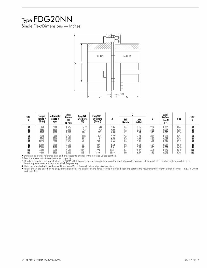
Type FDG20NNSingle Flex/Dimensions — Inches
© The Falk Corporation, 2002, 2004. (471-710) 17
SIZE�
TorqueRating †
(lb-in)
AllowableSpeed ‡
rpm
MaxBore �
StdN-Hub
Cplg Wtw/o Bore
(lb)
Cplg WR2
w/o Bore(lb-in2)
A
C
D
AxialDeflec-tion �+/–
GapSIZE
�StdN-Hub
LongN-Hub
20 840 5800 1.625 5.19 5.08 3.46 1.77 3.15 2.36 0.035 0.264 2030 1550 5600 2.000 7.28 7.39 4.02 1.77 3.15 2.76 0.024 0.256 3040 2740 4600 2.250 11.4 22.2 4.84 1.97 3.54 3.23 0.028 0.276 40
50 5090 3900 2.750 18.8 46.5 5.79 2.36 3.94 3.94 0.031 0.354 5060 7740 3500 3.250 31.1 113 6.54 2.76 4.33 4.53 0.039 0.394 6070 12390 3000 3.625 53.1 240 7.56 3.74 5.31 5.20 0.047 0.512 70
80 13000 2700 3.500 60.4 337 8.58 3.96 5.53 5.04 0.051 0.610 8090 23000 2400 4.000 82.2 562 9.61 4.31 5.89 5.75 0.059 0.610 90
100 33600 2200 4.500 112 924 10.31 4.74 6.32 6.38 0.067 0.610 100110 44000 1900 5.000 145 1540 11.89 5.00 6.57 6.93 0.075 0.748 110
� Dimensions are for reference only and are subject to change without notice unless certified.† Peak torque capacity is two times rated capacity.‡ Standard couplings are manufactured to AGMA 9000 balance class 7. Speeds shown are for applications with average system sensitivity. For other system sensitivities or
balancing recommendations, contact Falk Engineering.� Hubs are furnished with interference fit per Table 25 on Page 51 unless otherwise specified.� Values shown are based on no angular misalignment. The axial centering force restricts motor end float and satisfies the requirements of NEMA standards MG1-14.37, 1-20.81
and 1-21.81.
GAPCC
A D
N-HUB N-HUB

Type FDG20ANSingle Flex/Dimensions — Inches
18 (471-710) © The Falk Corporation, 2002, 2004.
F A L K
GAP
A D D
CC
A HUBN HUB
SIZE�
TorqueRating †
(lb-in)
AllowableSpeed ‡
rpm
Max Bore �Cplg Wtw/o Bore
(lb)
Cplg WR2
w/o Bore(lb-in2)
A
C D AxialDeflec-tion �+/–
GapSIZE
�N Hub A HubStd
N HubStd
A HubLong
N-HubLong
A-HubN Hub A Hub
20 840 5800 1.625 1.625 5.91 6.55 3.46 1.77 1.77 3.15 3.15 2.36 2.36 0.035 0.618 2030 1550 5600 2.000 2.000 8.16 10.7 4.02 1.77 1.77 3.15 3.15 2.76 2.76 0.024 0.610 3040 2740 4600 2.250 2.250 13.2 30.7 4.84 1.97 1.97 3.54 3.54 3.23 3.23 0.028 0.748 40
50 5090 3900 2.750 2.750 22.4 65.2 5.79 2.36 2.36 3.94 3.94 3.94 3.94 0.031 0.906 5060 7740 3500 3.250 3.250 36.1 147 6.54 2.76 2.76 4.33 4.33 4.53 4.53 0.039 1.063 6070 12390 3000 3.625 3.625 60.4 311 7.56 3.74 3.74 5.31 5.31 5.20 5.20 0.047 1.260 70
80 13000 2700 3.500 3.500 68.0 429 8.58 3.96 3.96 5.53 5.53 5.04 5.04 0.051 1.437 8090 23000 2400 4.000 4.000 91.4 701 9.61 4.31 4.31 5.89 5.89 5.75 5.75 0.059 1.437 90
100 33600 2200 4.500 4.500 126 1180 10.31 4.74 4.74 6.32 6.32 6.38 6.38 0.067 1.614 100110 44000 1900 5.000 5.000 165 2050 11.89 5.00 5.00 6.57 6.57 6.93 6.93 0.075 1.949 110
� Dimensions are for reference only and are subject to change without notice unless certified.† Peak torque capacity is two times rated capacity.‡ Standard couplings are manufactured to AGMA 9000 balance class 7. Speeds shown are for applications with average system sensitivity. For other system sensitivities or
balancing recommendations, contact Falk Engineering.� Hubs are furnished with interference fit per Table 25 on Page 51 unless otherwise specified.� Values shown are based on no angular misalignment. The axial centering force restricts motor end float and satisfies the requirements of NEMA standards MG1-14.37, 1-20.81
and 1-21.81.

Type FDG50NN, 55NNFloating Shaft Assemblies/Dimensions — Inches
© The Falk Corporation, 2002, 2004. (471-710) 19
BEC
SDDA
GAPGAP
Type N50
N-HUB N-HUB
SIZEType
ofShaft
Floating Shafts
Max BE for Various rpm’s �
1800 1500 1200 900 750 600540 &Less
20 Solid 48 52 58 68 74 83 87
Tube 60 67 74 86 94 105 111
30 Solid 52 57 64 74 81 91 96
Tube 75 82 91 105 115 129 136
40 Solid 58 64 72 83 91 102 107
Tube 82 90 100 116 127 142 150
50 Solid 60 66 74 86 94 105 111
Tube 90 99 110 128 140 156 165
60 Solid 68 74 83 96 105 117 124
Tube 93 102 114 131 144 161 170
70 Solid 74 81 91 105 115 129 136
Tube 106 116 130 150 164 183 193
� Interpolate for intermediate speeds. Max. BE is based on 70% of the lateral criticalspeed. Refer to Table 26 on Page 51 to determine if solid shaft requires balancing.Contact Falk for speeds in excess of 1800 rpm or lengths longer than shown.
SIZE�
TorqueRating †
(lb-in)
MaxBore �
StdN-Hub
Typeof
Shaft
MinBE
Weight (lb) � WR2 (lb-in2) �
Axial �Deflection
+/–A
C
D Gap
Floating Shaft
SIZE�Basic Cplg
w/No Bore
lbper inof BE
Basic Cplgw/No Bore
WR2
per inof BE
StdN-Hub
LongN-Hub
OD SD
20 840 1.625Solid 4.094 8.98 0.34 9.88 0.07
0.071 3.46 1.77 3.15 2.30 0.264. . . 1.250 20
Tube 13.189 7.23 0.11 7.90 0.06 1.500 . . .
30 1550 2.000Solid 4.094 12.5 0.50 14.2 0.14
0.047 4.02 1.77 3.15 2.74 0.256. . . 1.500 30
Tube 13.189 10.7 0.22 14.3 0.26 2.250 . . .
40 2740 2.250Solid 4.488 19.3 0.78 42.8 0.34
0.055 4.84 1.97 3.54 3.23 0.276. . . 1.875 40
Tube 13.386 17.3 0.34 39.5 0.61 2.750 . . .
50 5090 2.750Solid 5.433 32.7 0.90 90.7 0.44
0.063 5.79 2.36 3.94 3.84 0.354. . . 2.000 50
Tube 13.583 28.0 0.67 85.6 1.70 3.375 . . .
60 7740 3.250Solid 6.299 53.4 1.40 218 1.09
0.079 6.54 2.76 4.33 4.45 0.394. . . 2.500 60
Tube 14.173 45.6 0.56 190 1.52 3.500 . . .
70 12390 3.625 Solid 8.504 89.2 2.02 461 2.24 0.094 7.56 3.74 5.31 5.20 0.512 . . . 3.000 70Tube 14.370 75.6 0.73 404 3.34 4.500 . . .
� Dimensions are for reference only and are subject to change without notice unless certified.† Peak torque capacity is two times rated capacity.� Hubs are furnished with interference fit per Table 25 on Page 51 unless otherwise specified.� To obtain total weight: Basic Coupling + BE times Lbs. per in. of BE.� To obtain total WR2: Basic Coupling + BE times WR2 per in. of BE.
� Values shown are based on no angular misalignment. The axial centering force restricts motor end float and satisfies the requirements of NEMA standards MG1-14.37, 1-20.81and 1-21.81.
OD
BEC
DA
GAPGAP
Type N55
N-HUB N-HUB

Type FDG50AA, 55AAFloating Shaft Assemblies/Dimensions — Inches
20 (471-710) © The Falk Corporation, 2002, 2004.
F A L K
SIZEType
ofShaft
Floating Shafts
Max BE for Various rpm’s �
1800 1500 1200 900 750 600540 &Less
20 Solid 48 52 58 68 74 83 87
Tube 60 67 74 86 94 105 111
30 Solid 52 57 64 74 81 91 96
Tube 75 82 91 105 115 129 136
40 Solid 58 64 72 83 91 102 107
Tube 82 90 100 116 127 142 150
50 Solid 60 66 74 86 94 105 111
Tube 90 99 110 128 140 156 165
60 Solid 68 74 83 96 105 117 124
Tube 93 102 114 131 144 161 170
70 Solid 74 81 91 105 115 129 136
Tube 106 116 130 150 164 183 193
� Interpolate for intermediate speeds. Max. BE is based on 70% of the lateral criticalspeed. Refer to Table 26 on Page 51 to determine if solid shaft requires balancing.Contact Falk for speeds in excess of 1800 rpm or lengths longer than shown.
Type A50
SD
BECC
DDAA
GAP GAP
A-HUB A-HUB
OD
Type A55BECC
DDAA
GAP GAP
A-HUB A-HUB
SIZE�
TorqueRating †
(lb-in)
MaxBore �
StdHub
Typeof
Shaft
MinBE
Weight (lb) � WR2 (lb-in2) �
Axial �Deflection
+/–
A-Hub
Gap
Floating Shaft
SIZE�AA
CC
DDBasic Cplgw/No Bore
lbper inof BE
Basic Cplgw/No Bore
WR2
per inof BE
StdHub
LongHub
OD SD
20 840 1.625Solid 4.803 10.17 0.34 12.73 0.07
0.071 3.46 1.77 3.15 2.30 0.618. . . 1.250 20
Tube 13.583 8.58 0.11 10.62 0.06 1.500 . . .
30 1550 2.000Solid 4.803 13.9 0.50 20.7 0.14
0.047 4.02 1.77 3.15 2.74 0.610. . . 1.500 30
Tube 13.583 12.3 0.22 20.1 0.26 2.250 . . .
40 2740 2.250Solid 5.433 22.1 0.78 59.2 0.34
0.055 4.84 1.97 3.54 3.23 0.748. . . 1.875 40
Tube 13.976 20.5 0.34 53.9 0.61 2.750 . . .
50 5090 2.750Solid 6.535 38.9 0.90 127 0.44
0.063 5.79 2.36 3.94 3.84 0.906. . . 2.000 50
Tube 14.173 34.4 0.67 115 1.70 3.375 . . .
60 7740 3.250Solid 7.638 61.5 1.40 285 1.09
0.079 6.54 2.76 4.33 4.45 1.063. . . 2.500 60
Tube 14.764 54.8 0.56 250 1.52 3.500 . . .
70 12390 3.625 Solid 10.000 101 2.02 597 2.24 0.094 7.56 3.74 5.31 5.20 1.260 . . . 3.000 70Tube 15.157 89.2 0.73 522 3.34 4.500 . . .
� Dimensions are for reference only and are subject to change without notice unless certified.† Peak torque capacity is two times rated capacity.� Hubs are furnished with interference fit per Table 25 on Page 51 unless otherwise specified.� To obtain total weight: Basic Coupling + BE times Lbs. per in. of BE.� To obtain total WR2: Basic Coupling + BE times WR2 per in. of BE.
� Values shown are based on no angular misalignment. The axial centering force restricts motor end float and satisfies the requirements of NEMA standards MG1-14.37, 1-20.81and 1-21.81.

Freedom Disc CouplingType FDP (Pages 21 thru 29)
� Ideally suited for applications requiring less than 153,000 lb-in
� Multiple discs made from 301 grade stainless for corrosionresistance. Separated by washers to prevent fretting corrosionbetween disc blades
� Dacromet® coated drive bolts
� Non-lubricated, low maintenance design for improvedproductivity
� Manufactured to meet the following AGMA balance classType 10 – AGMA 8Type 30 – AGMA 9Type 31 – AGMA 9
� Zero backlash for precise synchronization and timing ofequipment
� Conformance to API 610 8th or 9th edition when specified
� Can be visually inspected
� Discpacks can be removed and replaced without moving theconnected equipment
� Suitable for vertical operation without modification
Freedom Disc Coupling Nomenclature20 FDP 10 CC B A
PRODUCT COUPLING HUB 1 & HUB 2SIZE CLASSIFICATION TYPE EACH HUB DESCRIPTION FEATURE MODEL20 Freedom Disc 10 = Close Coupled A = Adapter Type B = Balanced A, B etc.Thru Performance 11 = Close Coupled, C = Close Coupled Type P = Electrically125 One hub reversed Narrow Gap (Long Hubs) Insulated
12 = Close Coupled only used on 10 Series V = VerticalTwo hubs reversed D = Close Coupled Type S = Special
20 = Single Flexing. Wide Gap (Short Hubs)This type must always DBZ Interchange only usedcontain one “N” non- on 10 Seriesadapter type hub in the G = Gear Coupling Retrofithub description block Exposed, normally used
30 = Spacer - Non Adapter Style on floating shafts31 = Spacer - Adapter Style H = Gear Coupling Retrofit50 = Floating Shaft - Solid Shrouded, normally used55 = Floating Shaft - Tubular on floating shafts
L = Large Hub Adapter TypeN = Non-Adapter Type
© The Falk Corporation, 2002, 2004. (471-710) 21

Type FDP10CC, 11CC & 12CCDimensions — Inches
22 (471-710) © The Falk Corporation, 2002, 2003.
F A L K
SIZE�
TorqueRating †
(lb-in)
AllowableSpeed ‡
rpm
MaxBore �
Cplg Wtw/o Bore
(lb)
Cplg WR2
w/o Bore(lb-in2)
A
B
C D H
Gap AxialDeflec-tion �+/–
SIZE�FDP10 FDP11 FDP12 FDP10 FDP11 FDP12
20 1285 7900 1.125 6.02 7.32 3.46 3.94 4.80 5.67 1.81 1.57 0.26 0.31 1.18 2.05 0.094 2030 2200 6800 1.625 9.56 15.0 4.02 4.06 4.98 5.91 1.87 2.32 0.26 0.31 1.24 2.17 0.079 3040 4960 5500 1.875 17.5 40.2 4.84 4.92 5.98 7.05 2.28 2.76 0.28 0.35 1.42 2.48 0.094 4050 8850 4700 2.250 29.8 97.1 5.79 5.94 7.28 8.62 2.76 3.23 0.35 0.43 1.77 3.11 0.102 5060 14700 4200 2.625 49.8 261 6.54 7.36 9.04 10.71 3.44 3.82 0.39 0.47 2.15 3.82 0.118 6070 23000 3600 3.000 75.4 463 7.56 8.19 10.14 12.09 3.80 4.41 0.51 0.59 2.54 4.49 0.157 70
85 44250 3100 3.500 104.3 801 8.82 9.41 11.69 13.98 4.41 4.92 0.55 0.59 2.87 5.16 0.157 8595 61950 2850 4.000 157 1150 9.61 10.91 13.39 15.87 5.12 5.91 0.61 0.67 3.15 5.63 0.173 95
105 84520 2550 4.500 202 2700 10.75 11.85 14.49 17.13 5.51 6.46 0.75 0.83 3.46 6.10 0.205 105115 110200 2300 5.000 269 3900 11.93 12.83 15.79 18.74 5.98 7.09 0.79 0.87 3.82 6.77 0.260 115125 153300 2000 6.000 374 6780 13.39 13.78 16.77 19.76 6.46 8.43 0.79 0.87 3.86 6.85 0.268 125
� Dimensions are for reference only and are subject to change without notice unless certified.† Peak torque capacity is two times rated capacity.‡ Standard couplings are manufactured to AGMA 9000 balance class 8. Speeds shown are for applications with average system sensitivity. For other system sensitivities or
balancing recommendations, contact Falk Engineering.� Hubs are furnished with interference fit per Table 25 on Page 51 unless otherwise specified.� Values shown are based on no angular misalignment. The axial centering force restricts motor end float and satisfies the requirements of NEMA standards MG1-14.37, 1-20.81
and 1-21.81.
FDP10Standard Hub Configuration
FDP11One Hub Reversed
FDP12Two Hubs Reversed
H
D
B
A
GAPC C
D
B
A
GAP
C
H
C
H
D
B
A
GAP
C C

Type FDP30NNDimensions — Inches
© The Falk Corporation, 2002, 2004. (471-710) 23
CPLGSIZE
Standard “BE” Spacers
3.50 5.00 7.00 9.00
20 x x
30 x x
40 x x x
50 . . . x x
60 . . . x x
70 . . . . . . x
85 . . . x x
95 . . . . . . x
105 . . . . . . x
115 . . . . . . . . . x
125 . . . . . . . . . x
SIZE�
TorqueRating †
(lb-in)
AllowableSpeedrpm ‡
MaxBore �
StdN-Hub
MinBE
MaxBE
Cplg Wt �w/o Bore
(lb)
Cplg WR2 �
with no Bore(lb-in2) A
C
D
AxialDeflec-tion �+/–
SIZE�
BasicCplg
lb perin of BE
BasicCplg
WR2 perin of BE
StdN-Hub
LongN-Hub
20 1285 11000 1.625 2.97 13.2 6.48 0.426 7.46 0.175 3.46 1.77 3.15 2.30 0.094 2030 2200 10000 2.000 2.95 13.2 8.85 0.808 11.8 0.796 4.02 1.77 3.15 2.74 0.079 3040 4960 9300 2.250 3.39 13.4 14.7 0.989 34.7 1.43 4.84 1.97 3.54 3.23 0.094 4050 8850 8500 2.750 3.78 13.6 23.4 1.54 72.8 3.07 5.79 2.36 3.94 3.84 0.102 5060 14700 7600 3.250 4.37 14.2 39.5 1.85 216 4.95 6.54 2.76 4.33 4.45 0.118 6070 23000 6900 3.625 5.35 14.4 64.9 2.64 356 9.82 7.56 3.74 5.31 5.20 0.157 70
85 44250 6300 4.250 5.00 14.6 91.2 3.13 782 16.3 8.82 3.74 5.31 5.96 0.157 8595 61950 6000 4.625 6.57 15.0 131 4.35 1250 30.3 9.61 4.33 5.91 6.75 0.173 95
105 84520 5500 5.250 7.09 15.4 176 4.85 2110 41.6 10.75 4.92 6.50 7.46 0.205 105115 110200 5100 5.875 7.48 15.6 245 5.50 3670 60.7 11.93 5.51 7.09 8.33 0.260 115125 153300 4900 6.875 8.66 15.7 356 7.42 6880 109 13.39 6.30 7.87 9.63 0.268 125
� Dimensions are for reference only and are subject to change without notice unless certified.† Peak torque capacity is two times rated capacity.‡ Standard couplings are manufactured to AGMA 9000 balance class 9. Speeds shown are for applications with average system sensitivity. For other system sensitivities or
balancing recommendations, contact Falk Engineering.� Hubs are furnished with interference fit per Table 25 on Page 51 unless otherwise specified.� To obtain total weight: Basic Coupling + BE times lbs. per inch of BE.� To obtain total WR2: Basic Coupling + BE times WR2 per inch of BE.� Values shown are based on no angular misalignment. The axial centering force restricts motor end float and satisfies the requirements of NEMA
standards MG1-14.37, 1-20.81 and 1-21.81.
BE CC
A D
N-HUB N-HUB

Type FDP31AA, LL, & ALDimensions — Inches
24 (471-710) © The Falk Corporation, 2002, 2004.
F A L K
CPLGSIZE
Standard “BE” Spacers
3.50 5.00 7.00 8.00 9.00
20 x x
30 x x
40 x x x
50 . . . x x
60 . . . x x
70 . . . . . . x
85 . . . . . . x
95 . . . . . . . . . x
105 . . . . . . . . . x
115 . . . . . . . . . . . . x
125 . . . . . . . . . . . . x
SIZE�
TorqueRating †
(lb-in)
AllowableSpeedrpm ‡
MaxBore �
StdA-Hub
MaxBore �LargeL-Hub
MinBE
MaxBE
Cplg Wt �w/o Bore
(lb)
Cplg WR2 �
w/o Bore(lb-in2) A
C
D M
AxialDeflec-tion �+/–
SIZE�
BasicCplg
lb perin of BE
BasicCplg
WR2 perin of BE
StdA-Hub
LargeL-Hub
20 1285 11000 1.625 2.250 2.73 13.58 7.79 0.426 10.3 0.175 3.46 1.77 1.73 2.30 0.59 0.094 2030 2200 10000 2.000 2.750 2.72 13.58 10.4 0.808 18.6 0.796 4.02 1.77 2.13 2.74 0.59 0.079 3040 4960 9300 2.250 3.375 3.43 13.98 18.1 0.989 48.3 1.43 4.84 1.97 2.28 3.23 0.79 0.094 4050 8850 8500 2.750 4.125 3.74 14.17 29.7 1.54 113 3.07 5.79 2.36 2.95 3.84 0.79 0.102 5060 14700 7600 3.250 4.625 4.84 14.76 47.8 1.85 281 4.95 6.54 2.76 3.58 4.45 1.18 0.118 6070 23000 6900 3.625 5.250 5.67 15.16 78.2 2.64 490 9.82 7.56 3.74 3.94 5.20 1.18 0.157 70
85 44250 6300 5.000 6.250 6.02 15.55 123 3.13 992 16.3 8.82 3.74 4.17 6.89 1.38 0.098 8595 61950 6000 5.250 6.750 7.20 16.14 167 4.35 1710 30.3 9.61 4.33 4.41 7.48 1.57 0.110 95
105 84520 5500 6.000 7.500 7.87 16.54 234 4.85 3020 41.6 10.75 4.92 5.12 8.47 1.77 0.102 105115 110200 5100 6.500 8.500 8.50 16.93 318 5.50 4980 60.7 11.93 5.51 5.75 9.25 1.97 0.118 115125 153300 4900 7.500 9.500 9.02 17.32 456 7.42 9330 109 13.39 6.30 6.46 10.63 1.97 0.134 125
� Dimensions are for reference only and are subject to change without notice unless certified.† Peak torque capacity is two times rated capacity.‡ Standard couplings are manufactured to AGMA 9000 balance class 9. Speeds shown are for applications with average system sensitivity. For other system sensitivities or
balancing recommendations, contact Falk Engineering.� Hubs are furnished with interference fit per Table 25 on Page 51 unless otherwise specified.� To obtain total weight: Basic Coupling + BE times lbs. per in. of BE.� To obtain total WR2: Basic Coupling + BE times WR2 per in. of BE.� Values shown are based on no angular misalignment. The axial centering force restricts motor end float and satisfies the requirements of NEMA
standards MG1-14.37, 1-20.81 and 1-21.81.
ANTI-FLYADAPTER
CBEC
DA
M
M
M
L-HUB L-HUB
A-HUB
L-HUB
A-HUB
A-HUB
TWO STANDARD HUBS (AA)
TWO LARGE HUBS (LL)
ONE STANDARD & ONE LARGE HUB (AL)

Type FDP20NNSingle Flex/Dimensions — Inches
© The Falk Corporation, 2002, 2004. (471-710) 25
SIZE�
TorqueRating †
(lb-in)
AllowableSpeed ‡
rpm
MaxBore�
StdN-Hub
Cplg Wtw/o Bore
(lb)
Cplg WR2
w/o Bore(lb-in2)
A
C
D
AxialDeflec-tion �+/–
GapSIZE
�StdN-Hub
LongN-Hub
20 1285 7900 1.625 5.22 5.09 3.46 1.77 3.15 2.30 0.047 0.264 2030 2200 6800 2.000 7.32 7.45 4.02 1.77 3.15 2.74 0.039 0.256 3040 4960 5500 2.250 11.4 22.5 4.84 1.97 3.54 3.23 0.047 0.276 4050 8850 4700 2.750 18.7 47.0 5.79 2.36 3.94 3.84 0.051 0.354 5060 14700 4200 3.250 31.2 136 6.54 2.76 4.33 4.45 0.059 0.394 6070 23000 3600 3.625 53.4 243 7.56 3.74 5.31 5.20 0.079 0.512 70
85 44250 3100 4.250 74.7 650 8.82 3.74 5.31 5.96 0.079 0.551 8595 61950 2850 4.625 108 1010 9.61 4.33 5.91 6.75 0.087 0.610 95
105 84520 2550 5.250 147 1740 10.75 4.92 6.50 7.46 0.102 0.748 105115 110200 2300 5.875 205 3030 11.93 5.51 7.09 8.33 0.130 0.787 115125 153300 2000 6.875 303 5850 13.39 6.30 7.87 9.63 0.134 0.787 125
� Dimensions are for reference only and are subject to change without notice unless certified.† Peak torque capacity is two times rated capacity.‡ Standard couplings are manufactured to AGMA 9000 balance class 7. Speeds shown are for applications with average system sensitivity. For other system sensitivities or
balancing recommendations, contact Falk Engineering.� Hubs are furnished with interference fit per Table 25 on Page 51 unless otherwise specified.� Values shown are based on no angular misalignment. The axial centering force restricts motor end float and satisfies the requirements of NEMA standards MG1-14.37, 1-20.81
and 1-21.81.
GAPCC
DA
N-HUB N-HUB

Type FDP20ANSingle Flex/Dimensions — Inches
26 (471-710) © The Falk Corporation, 2002, 2004.
F A L K
GAPCC
DDA
N HUB A HUB
SIZE�
TorqueRating †
(lb-in)
AllowableSpeed ‡
rpm
Max Bore �Cplg Wtw/o Bore
(lb)
Cplg WR2
w/o Bore(lb-in2)
A
C D AxialDeflec-tion �+/–
GapSIZE
�N Hub A Hub N Hub A Hub N Hub A Hub
20 1285 7900 1.625 1.625 5.22 5.09 3.46 1.77 1.77 2.30 2.30 0.047 0.618 2030 2200 6800 2.000 2.000 7.32 7.4 4.02 1.77 1.77 2.74 2.74 0.039 0.610 3040 4960 5500 2.250 2.250 11.4 22.5 4.84 1.97 1.97 3.23 3.23 0.047 0.748 4050 8850 4700 2.750 2.750 18.7 47.0 5.79 2.36 2.36 3.84 3.84 0.051 0.906 5060 14700 4200 3.250 3.250 31.2 136 6.54 2.76 2.76 4.45 4.45 0.059 1.063 6070 23000 3600 3.625 3.625 53.4 243 7.56 3.74 3.74 5.20 5.20 0.079 1.260 70
85 44250 3100 4.250 5.000 74.7 650 8.82 3.74 3.74 5.96 6.89 0.079 1.417 8595 61950 2850 4.625 5.250 108 1010 9.61 4.33 4.33 6.75 7.48 0.087 1.614 95
105 84520 2550 5.250 6.000 147 1740 10.75 4.92 4.92 7.46 8.46 0.102 1.831 105115 110200 2300 5.875 6.500 205 3030 11.93 5.51 5.51 8.33 9.25 0.130 1.988 115125 153300 2000 6.875 7.500 303 5850 13.39 6.30 6.30 9.63 10.63 0.134 2.067 125
� Dimensions are for reference only and are subject to change without notice unless certified.† Peak torque capacity is two times rated capacity.‡ Standard couplings are manufactured to AGMA 9000 balance class 7. Speeds shown are for applications with average system sensitivity. For other system sensitivities or
balancing recommendations, contact Falk Engineering.� Hubs are furnished with interference fit per Table 25 on Page 51 unless otherwise specified.� Values shown are based on no angular misalignment. The axial centering force restricts motor end float and satisfies the requirements of NEMA standards MG1-14.37, 1-20.81
and 1-21.81.

Type FDP50NN, 55NNFloating Shaft Assemblies/Dimensions — Inches
© The Falk Corporation, 2002, 2004. (471-710) 27
SIZEType
ofShaft
Floating Shafts
Max BE for Various rpm’s �
1800 1500 1200 900 750 600540 &Less
20 Solid 48 52 58 68 74 83 87
Tube 60 67 74 86 94 105 111
30 Solid 52 57 64 74 81 91 96
Tube 75 82 91 105 115 129 136
40 Solid 58 64 72 83 91 102 107
Tube 82 90 100 116 127 142 150
50 Solid 60 66 74 86 94 105 111
Tube 90 99 110 128 140 156 165
60 Solid 68 74 83 96 105 117 124
Tube 93 102 114 131 144 161 170
70 Solid 74 81 91 105 115 129 136
Tube 106 116 130 150 164 183 193
85 Solid 80 88 98 113 124 139 147
Tube 111 122 136 157 172 193 203
95 Solid 86 94 105 121 133 149 157
Tube 122 134 150 173 190 212 223
105 Solid 88 97 108 125 137 153 161
Tube 128 140 156 180 198 221 233
115 Solid 91 100 111 129 141 158 166
Tube 134 146 164 189 207 232 244
125 Solid 99 109 122 141 154 172 182
Tube 145 159 178 206 225 252 266
� Interpolate for intermediate speeds. Max. BE is based on 70% of the lateral criticalspeed. Refer to Table 26 on Page 51 to determine if solid shaft requires balancing.Contact Falk for speeds in excess of 1800 rpm or lengths longer than shown.
BEC
DA SD
GAPGAPGAPGAP
Type N50
N-HUB N-HUB
SIZE�
TorqueRating †
(lb-in)
MaxBore �
StdN-Hub
Typeof
Shaft
MinBE
Weight (lb) � WR2 (lb-in2) �
Axial �Deflection
+/–A
C
D Gap
Floating Shaft
SIZE�Basic Cplg
w/No Bore
lbper inof BE
Basic Cplgw/No Bore
WR2
per inof BE
StdN-Hub
LongN-Hub
OD SD
20 1285 1.625Solid 4.094 9.02 0.34 9.91 0.07
0.094 3.46 1.77 3.15 2.30 0.264. . . 1.250 20
Tube 13.189 7.27 0.11 7.92 0.06 1.500 . . .
30 2200 2.000Solid 4.094 12.6 0.50 14.3 0.14
0.079 4.02 1.77 3.15 2.74 0.256. . . 1.500 30
Tube 13.189 10.8 0.22 14.4 0.26 2.250 . . .
40 4960 2.250Solid 4.488 19.4 0.78 43.5 0.34
0.094 4.84 1.97 3.54 3.23 0.276. . . 1.875 40
Tube 13.386 17.4 0.34 40.2 0.61 2.750 . . .
50 8850 2.750Solid 5.433 32.7 0.90 91.7 0.44
0.102 5.79 2.36 3.94 3.84 0.354. . . 2.000 50
Tube 13.583 27.9 0.67 86.6 1.70 3.375 . . .
60 14700 3.250Solid 6.299 53.7 1.40 265 1.09
0.118 6.54 2.76 4.33 4.45 0.394. . . 2.500 60
Tube 14.173 45.8 0.56 237 1.52 3.500 . . .
70 23000 3.625Solid 8.504 89.9 2.02 468 2.24
0.157 7.56 3.74 5.31 5.20 0.512. . . 3.000 70
Tube 14.370 76.3 0.73 410 3.34 4.500 . . .
85 44250 4.250Solid 8.583 126 2.69 1260 4.15
0.157 8.82 3.74 5.31 5.96 0.551. . . 3.500 85
Tube 14.567 106 1.06 869 5.95 5.000 . . .
95 61950 4.625Solid 9.882 181 3.53 1950 7.09
0.173 9.61 4.33 5.91 6.75 0.610. . . 4.000 95
Tube 14.961 155 1.29 1350 10.55 6.000 . . .
105 84520 5.250Solid 11.339 249 3.98 3380 9.03
0.205 10.75 4.92 6.50 7.46 0.748. . . 4.250 105
Tube 15.354 204 1.40 2390 13.54 6.500 . . .
115 110200 5.875Solid 12.598 353 4.48 5910 11.37
0.260 11.93 5.51 7.09 8.33 0.787. . . 4.500 115
Tube 15.551 274 2.30 4100 27.07 7.250 . . .
125 153300 6.875 Solid 14.173 516 6.38 11400 23.09 0.268 13.39 6.30 7.87 9.63 0.787 . . . 5.375 125Tube 15.748 404 2.69 7700 44.65 8.500 . . .
� Dimensions are for reference only and are subject to change without notice unless certified.† Peak torque capacity is two times rated capacity.� Hubs are furnished with interference fit per Table 25 on Page 51 unless otherwise specified.� To obtain total weight: Basic Coupling + BE times Lbs. per in. of BE.� To obtain total WR2: Basic Coupling + BE times WR2 per in. of BE.
� Values shown are based on no angular misalignment. The axial centering force restricts motor end float and satisfies the requirements of NEMA standards MG1-14.37, 1-20.81and 1-21.81.
OD
BEC
DA
GAPGAP
Type N55
N-HUB N-HUB

Type FDP50AA, 55AAFloating Shaft Assemblies/Dimensions — Inches
28 (471-710) © The Falk Corporation, 2002, 2004.
F A L K
Type A50
SD
BECC
DDAA
GAP GAP
A-HUB A-HUB
OD
Type A55BECC
DDAA
GAP GAP
ANTI-FLYADAPTER
A-HUB
A-HUB
SIZEType
ofShaft
Floating Shafts
Max BE for Various rpm’s �
1800 1500 1200 900 750 600540 &Less
20 Solid 48 52 58 68 74 83 87
Tube 60 67 74 86 94 105 111
30 Solid 52 57 64 74 81 91 96
Tube 75 82 91 105 115 129 136
40 Solid 58 64 72 83 91 102 107
Tube 82 90 100 116 127 142 150
50 Solid 60 66 74 86 94 105 111
Tube 90 99 110 128 140 156 165
60 Solid 68 74 83 96 105 117 124
Tube 93 102 114 131 144 161 170
70 Solid 74 81 91 105 115 129 136
Tube 106 116 130 150 164 183 193
85 Solid 80 88 98 113 124 139 147
Tube 111 122 136 157 172 193 203
95 Solid 86 94 105 121 133 149 157
Tube 122 134 150 173 190 212 223
105 Solid 88 97 108 125 137 153 161
Tube 128 140 156 180 198 221 233
115 Solid 91 100 111 129 141 158 166
Tube 134 146 164 189 207 232 244
125 Solid 99 109 122 141 154 172 182
Tube 145 159 178 206 225 252 266
� Interpolate for intermediate speeds. Max. BE is based on 70% of the lateral criticalspeed. Refer to Table 26 on Page 51 to determine if solid shaft requires balancing.Contact Falk for speeds in excess of 1800 rpm or lengths longer than shown.
SIZE�
TorqueRating †
(lb-in)
MaxBore �
StdA-Hub
Typeof
Shaft
MinBE
Weight (lb) � WR2 (lb-in2) �
Axial �Deflection
+/–AA
CC
DD Gap
Floating Shaft
SIZE�Basic Cplg
w/No Bore
lbper inof BE
Basic Cplgw/No Bore
WR2
per inof BE
StdA-Hub
LongA-Hub
OD SD
20 1285 1.625Solid 4.803 10.2 0.34 12.8 0.07
0.094 3.46 1.77 3.15 2.30 0.618. . . 1.250 20
Tube 13.583 8.63 0.11 10.7 0.06 1.500 . . .
30 2200 2.000Solid 4.803 14.0 0.50 20.9 0.14
0.079 4.02 1.77 3.15 2.74 0.610. . . 1.500 30
Tube 13.583 12.3 0.22 20.3 0.26 2.250 . . .
40 4960 2.250Solid 5.433 22.3 0.78 60.2 0.34
0.094 4.84 1.97 3.54 3.23 0.748. . . 1.875 40
Tube 13.976 20.7 0.34 54.9 0.61 2.750 . . .
50 8850 2.750Solid 6.535 39.2 0.90 128 0.44
0.102 5.79 2.36 3.94 3.84 0.906. . . 2.000 50
Tube 14.173 34.6 0.67 117 1.70 3.375 . . .
60 14700 3.250Solid 7.638 61.8 1.40 333 1.09
0.118 6.54 2.76 4.33 4.45 1.063. . . 2.500 60
Tube 14.764 55.1 0.56 298 1.52 3.500 . . .
70 23000 3.625Solid 10.000 102 2.02 607 2.24
0.157 7.56 3.74 5.31 5.20 1.260. . . 3.000 70
Tube 15.157 90.0 0.73 531 3.34 4.500 . . .
85 44250 5.000Solid 10.315 155 2.69 1490 4.15
0.157 8.82 3.74 5.31 6.89 1.417. . . 3.500 85
Tube 15.551 138 1.06 1060 5.95 5.000 . . .
95 61950 5.250Solid 11.890 213 3.53 2410 7.09
0.173 9.61 4.33 5.91 7.48 1.614. . . 4.000 95
Tube 16.142 192 1.29 1740 10.55 6.000 . . .
105 84520 6.000Solid 13.504 302 3.98 4330 9.03
0.205 10.75 4.92 6.50 8.47 1.831. . . 4.250 105
Tube 16.535 262 1.40 3230 13.54 6.500 . . .
115 110200 6.500Solid 15.000 419 4.48 7300 11.37
0.260 11.93 5.51 7.09 9.25 1.988. . . 4.500 115
Tube 16.929 346 2.30 5260 27.07 7.250 . . .
125 153300 7.500 Solid 16.732 603 6.38 13900 23.09 0.268 13.39 6.30 7.87 10.63 2.067 . . . 5.375 125Tube 17.323 500 2.69 9880 44.65 8.500 . . .
� Dimensions are for reference only and are subject to change without notice unless certified.† Peak torque capacity is two times rated capacity.� Hubs are furnished with interference fit per Table 25 on Page 51 unless otherwise specified.� To obtain total weight: Basic Coupling + BE times Lbs. per in. of BE.� To obtain total WR2: Basic Coupling + BE times WR2 per in. of BE.
� Values shown are based on no angular misalignment. The axial centering force restricts motor end float and satisfies the requirements of NEMA standards MG1-14.37, 1-20.81and 1-21.81.

Type FDP55GG, 55HHGear to Disc Retrofit Assemblies/Dimensions — Inches
© The Falk Corporation, 2002, 2004. (471-710) 29
BE
OD
HCC
F D
LIFELIGN GEARCPLG SIZE �
FREEDOM DISCCPLG SIZE �
Assy Torque Rating(lb-in)
Adapter Style FD
(Ref.)CC
MinBE
H
1010G50FDP 8,850 1 5.79
4.564.37 12.52 0.35
60FDP 10,080 2 6.54 4.13 12.64 0.39
1015G60FDP 14,700 1 6.54
6.004.33 13.04 0.39
70FDP 20,790 2 7.56 6.06 17.47 0.51
1020G70FDP 23,000 1 7.56
7.006.06 17.47 0.51
85FDP 37,800 2 8.82 5.94 17.71 0.55
1025G85FDP 44,250 1 8.82
8.376.05 17.93 0.55
95FDP 61,950 2 9.61 5.74 18.05 0.61
1030G105FDP 84,520 1 10.75
9.445.46 18.01 0.75
115FDP 107,100 2 11.93 7.30 22.09 0.79
1035G115FDP 110,200 1 11.93
11.007.56 22.61 0.79
125FDP 153,300 2 13.39 7.44 23.55 0.79
1040G 125FDP 153,300 1 13.39 12.50 7.44 23.55 0.79� Dimensions are for reference only and are subject to change without notice unless certified.
Gear-to-disc coupling floating shaft conversions replacelubricated, maintenance intensive gear coupling floating shaftswith non-lubricated Freedom disc couplings. Utilizing adapterplates or spools, these low maintenance assemblies bolt up to theexisting gear coupling rigid hubs. Can be furnished with or withoutshafts. Most commonly found on in-shafts to paper machines.
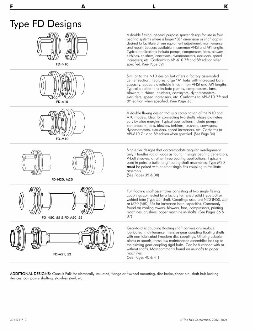
Type FD Designs
30 (471-710) © The Falk Corporation, 2002, 2004.
F A L K
FD-N10
FD-A10
FD-M10
FD-N20, M20
FD-N50, 55 & FD-A50, 55
FD-A51, 52
A double flexing, general purpose spacer design for use in fourbearing systems where a larger “BE” dimension or shaft gap isdesired to facilitate driven equipment adjustment, maintenance,and repair. Spacers available in common ANSI and API lengths.Typical applications include pumps, compressors, fans, blowers,turbines, crushers, conveyors, dynamometers, extruders, speedincreasers, etc. Conforms to API-610 7th and 8th edition whenspecified. (See Page 32)
Similar to the N10 design but offers a factory assembledcenter section. Features large “A” hubs with increased borecapacity. Spacers available in common ANSI and API lengths.Typical applications include pumps, compressors, fans,blowers, turbines, crushers, conveyors, dynamometers,extruders, speed increasers, etc. Conforms to API-610 7th and8th edition when specified. (See Page 33)
A double flexing design that is a combination of the N10 andA10 models. Ideal for connecting two shafts whose diametersvary by wide margins. Typical applications include pumps,compressors, fans, blowers, turbines, crushers, conveyors,dynamometers, extruders, speed increasers, etc. Conforms toAPI-610 7th and 8th edition when specified. (See Page 34)
Single flex designs that accommodate angular misalignmentonly. Handles radial loads as found in single bearing generators,V-belt sheaves, or other three bearing applications. Typicallyused in pairs to build long floating shaft assemblies. Type M20must be paired with another single flex coupling to facilitateassembly.(See Pages 35 & 38)
Full floating shaft assemblies consisting of two single flexingcouplings connected by a factory furnished solid (Type 50) orwelded tube (Type 55) shaft. Couplings used are N20 (N50, 55)or M20 (A50, 55) for increased bore capacities. Commonlyfound on cooling towers, blowers, fans, compressors, printingmachines, crushers, paper machine in-shafts. (See Pages 36 &37)
Gear-to-disc coupling floating shaft conversions replacelubricated, maintenance intensive gear coupling floating shaftswith non-lubricated Freedom disc couplings. Utilizing adapterplates or spools, these low maintenance assemblies bolt up tothe existing gear coupling rigid hubs. Can be furnished with orwithout shafts. Most commonly found on in-shafts to papermachines.(See Pages 40 & 41)
ADDITIONAL DESIGNS: Consult Falk for electrically insulated, flange or flywheel mounting, disc brake, shear pin, shaft-hub lockingdevices, composite shafting, stainless steel, etc.

Freedom Disc CouplingType FD (Pages 31 thru 41)
� Ideally suited for applications requiring more than 153,000lb-in
� Multiple discs made from 301 grade stainless for corrosionresistance.
� High strength drive bolts for greater reliability
� Non-lubricated, low maintenance design for improvedproductivity
� Manufactured to meet the following AGMA balance classType N10 – AGMA 8Type A10 – AGMA 9
� Zero backlash for precise synchronization and timing ofequipment
� Conformance to API 610 8th or 9th edition when specified
� Can be visually inspected
� Discpacks can be removed and replaced without moving theconnected equipment
� Suitable for vertical operation without modification
Freedom Disc Coupling Nomenclature2500 FD 06 N 10 B 1
SIZE PRODUCT NUMBER HUB MODIFI-
Refers to HP per CLASSIFICATION OF BOLTS DESCRIPTION TYPE CATIONS MODEL
1000 RPM. Falk Disc 04, 06, 08, A = Adapter 10 = Spacer B = Balanced 1, 2, 3,Example: 2500 10, or 12 C = Close 20 = Single Flex I = Insulated etc.rates 2500 HP Coupled 25 = Radial Load L = Limitedper 1000 RPM. M = Mixed 45 = Shear Pin End Float
N = General 50 = Solid Floating Shaft S = SpecialPurpose 51 = Gear to Disc Retrofit T = Thrust
(Shrouded Bolts) Transmitting52 = Gear to Disc Retrofit V = Vertical
(Exposed Bolts)55 = Tubular Floating Shaft56 = Tubular Floating Shaft
(Plugged Ends)57 = Tubular Floating Shaft
(One End Plugged)61 = Brakewheel63 = Disc Brake80 = Low Speed90 = Flywheel
© The Falk Corporation, 2002, 2004. (471-710) 31

Type FD-N10Large Sizes/Dimensions — Inches
32 (471-710) © The Falk Corporation, 2002, 2004.
F A L K
SIZE�
TorqueRating †
(lb-in)
Allowable Speedrpm ‡ Max
Bore �Recom
Key
MinBore
MinBE
MaxBE
Wt (lb) �at Max Bore
WR2 (lb-in2) �
at Max.Bore
A
C
D
AxialDeflec-tion �+/–
SIZE�AGMA
Class 8AGMAClass 9
BasicCplg
lbPer inof BE
BasicCplg
WR2
Per inof BE
StdN-Hub
2500FD08 157,600 4,420 6,400 5.000 2.50 9.00 19.0 138 1.65 2,000 9.22 10.85 5.00 7.18 .170 2500FD083160FD08 199,100 4,140 5,700 6.000 2.75 9.25 21.0 191 1.74 3,740 13.9 12.13 5.75 8.41 .196 3160FD08
4630FD08 291,800 3,560 5,700 6.875 3.00 9.75 24.0 265 2.36 6,540 26.6 13.63 6.50 9.46 .231 4630FD086470FD08 407,800 3,520 5,200 7.500 3.50 11.87 26.0 345 2.95 10,160 41.2 14.76 6.75 10.27 .243 6470FD088770FD08 552,700 3,310 4,700 8.250 4.00 12.50 28.0 445 3.53 16,500 56.7 16.15 7.50 11.08 .255 8770FD08
11000FD08 693,300 3,200 4,330 8.750 4.50 15.25 32.0 600 4.22 27,900 95.6 18.50 9.00 12.70 .327 11000FD0813000FD08 819,300 3,050 4,221 10.000 4.50 15.50 35.0 735 4.67 43,100 129 20.10 10.00 13.15 .364 13000FD0814000FD10 882,000 3,070 4,330 8.500 4.50 15.25 32.0 685 6.20 29,600 133 18.50 10.94 11.70 .283 14000FD10
15300FD08 964,300 2,910 3,580 11.000 5.00 17.00 37.5 925 5.11 64,000 169 21.90 10.50 14.35 .382 15300FD0816800FD10 1,058,000 2,900 3,990 9.750 4.50 15.50 35.0 890 6.80 46,400 181 20.10 12.29 13.15 .264 16800FD1017200FD12 1,084,000 3,020 4,330 8.500 4.50 15.25 32.0 685 8.00 29,300 164 18.50 10.94 11.70 .179 17200FD12
18500FD08 1,166,000 2,780 3,350 11.500 5.00 17.75 39.5 1130 6.09 93,200 236 23.10 11.00 15.05 .414 18500FD0819700FD10 1,241,000 2,760 3,660 10.750 5.00 17.00 37.5 1130 7.50 69,700 239 21.90 13.50 14.35 .283 19700FD1020000FD12 1,260,000 2,880 3,990 9.750 4.50 15.50 35.0 890 8.10 46,100 208 20.10 12.29 13.15 .199 20000FD12
23800FD10 1,499,000 2,690 3,470 11.500 5.00 17.75 39.5 1260 8.20 92,500 308 23.10 14.01 15.05 .299 23800FD1024000FD12 1,512,000 2,740 3,660 10.750 5.00 17.00 37.5 1130 8.90 69,200 276 21.90 13.50 14.35 .212 24000FD1224000FD08 1,512,600 2,640 3,240 12.000 5.00 19.00 42.5 1360 7.14 125,000 273 24.75 11.50 15.70 .434 24000FD08
28000FD08 1,764,700 2,580 3,110 13.000 5.00 19.25 44.0 1500 7.71 131,000 345 25.75 12.00 16.50 .484 28000FD0829000FD12 1,827,000 2,670 3,470 11.500 5.00 17.75 39.5 1260 9.70 91,900 357 23.10 14.01 15.05 .223 29000FD1231000FD10 1,953,000 2,530 3,240 11.500 5.00 19.00 42.5 1640 9.80 127,000 394 24.75 14.65 15.70 .315 31000FD10
36000FD10 2,268,000 2,480 3,110 12.750 5.00 19.25 44.0 1780 11.60 158,000 492 25.75 15.36 16.50 .335 36000FD1037700FD12 2,375,000 2,510 3,240 11.500 5.00 19.00 42.5 1640 12.40 126,000 478 24.75 14.65 15.70 .234 37700FD1244000FD12 2,772,000 2,450 3,110 12.750 5.00 19.25 44.0 1780 14.20 157,000 582 25.75 15.36 16.50 .248 44000FD12
� Dimensions are for reference only and are subject to change without notice unless certified.† Peak torque capacity is two times rated capacity.‡ Standard couplings are manufactured to AGMA 9000 balance class 8. Maximum speeds are AGMA Class 9. Speeds shown are for applications with average system sensitivity.
For other system sensitivities or balancing recommendations, contact Falk Engineering.� Hubs are furnished with interference fit per Table 25 on Page 51 unless otherwise specified.� To obtain total weight: Basic Coupling + BE times lbs. per in. of BE.� To obtain total WR2: Basic Coupling + BE times WR2 per in. of BE.� Values shown are based on no angular misalignment. The axial centering force restricts motor end float and satisfies the requirements of NEMA standards MG1-14.37, 1-20.81
and 1-21.81.
DA
C BE C
N-HUBN-HUB
CPLGSIZE
Standard “BE” Spacers
9.00 9.25
2500FD08 x3160FD08 x
4630FD08Not Stocked6470FD08
8770FD08

Type FD-A10Large Sizes/Dimensions — Inches
© The Falk Corporation, 2002, 2004. (471-710) 33
SIZE�
TorqueRating †
(lb-in)
Allowable Speedrpm ‡ Max
Bore �Recom
Key
MinBore
MinBE
MaxBE
Wt (lb) �at Max Bore
WR2 (lb-in2) �
at Max Bore
AA
CC
DD
AxialDeflec-tion �+/–
SIZE�AGMA
Class 8AGMAClass 9
BasicCplg
lbPer inof BE
BasicCplg
WR2
Per inof BE
StdA-Hub
2500FD08 157,600 . . . 5,910 5.875 2.50 9.00 22 188 1.65 3,120 9.22 10.85 5.08 8.38 .170 2500FD083160FD08 199,100 . . . 5,470 7.000 2.75 9.75 24 275 1.74 5,950 13.9 12.13 5.83 9.96 .196 3160FD08
4630FD08 291,800 . . . 5,100 8.000 3.00 10.75 27 365 2.36 10,180 26.6 13.63 6.58 11.02 .231 4630FD086470FD08 407,800 . . . 4,750 8.750 3.50 12.25 30 500 2.95 16,410 41.2 14.76 6.83 12.40 .243 6470FD088770FD08 552,700 . . . 4,460 9.625 4.00 14.00 33 665 3.53 26,670 56.7 16.15 7.58 13.46 .255 8770FD08
11000FD08 693,300 2,860 4,330 11.125 4.50 15.38 37 1,020 4.22 52,600 95.6 18.50 9.08 15.59 .327 11000FD0813000FD08 819,300 2,730 3,990 12.500 4.50 16.28 40 1,260 4.67 79,600 129 20.10 10.08 17.32 .364 13000FD0815300FD08 964,300 2,580 3,580 13.625 5.00 16.74 43 1,650 5.11 122,000 169 21.90 10.58 19.06 .382 15300FD08
18500FD08 1,166,000 2,120 3,350 14.250 5.00 18.10 46 1,940 6.09 160,000 236 23.10 11.08 19.84 .414 18500FD0824000FD08 1,512,600 2,380 3,240 14.250 5.00 19.84 49 2,320 7.14 208,000 273 24.75 11.58 20.08 .434 24000FD0828000FD08 1,764,700 2,300 3,110 15.750 5.00 20.64 51 2,680 7.71 272,000 345 25.75 12.08 22.05 .484 28000FD08
� Dimensions are for reference only and are subject to change without notice unless certified.† Peak torque capacity is two times rated capacity.‡ Standard couplings are manufactured to AGMA 9000 balance class 9. Speeds shown are for applications with average system sensitivity. For other system sensitivities or
balancing recommendations, contact Falk Engineering.� Hubs are furnished with interference fit per Table 25 on Page 51 unless otherwise specified.� To obtain total weight: Basic Coupling + BE times lbs. per in. of BE.� To obtain total WR2: Basic Coupling + BE times WR2 per in. of BE.� Values shown are based on no angular misalignment. The axial centering force restricts motor end float and satisfies the requirements of NEMA standards MG1-14.37, 1-20.81
and 1-21.81.
DDAA
CC BE CC
A-HUB A-HUB
CPLGSIZE
Standard “BE” Spacers
11.46 12.17
2500FD08 x
3160FD08 . . . x
4630FD08Not Stocked6470FD08
8770FD08

Type FD-M10Large Sizes/Dimensions — Inches
34 (471-710) © The Falk Corporation, 2002, 2004.
F A L K
SIZE�
TorqueRating †
(lb-in)
AllowableSpeed – rpm ‡
Max Bore �Recom Key
MinBore
MinBE
MaxBE
Wt (lb) �at Max Bore
WR2 (lb-in2) �
at Max BoreA-Hub N-Hub
AxialDeflect-
ion �+/–
SIZE�AGMA
Class 8AGMAClass 9
AHub
NHub
BasicCplg
lbPer inof BE
BasicCplg
WR2
Per inof BE
AA
CC
DD A
C
DStdHub
StdHub
2500FD08 157,600 4,240 6,400 5.875 5.000 2.50 10.23 21.00 161 1.65 2,560 9.22 10.85 5.08 8.38 10.85 5.00 7.18 .170 2500FD083160FD08 199,100 4,110 5,700 7.000 6.000 2.75 10.71 23.00 263 1.74 4,850 13.9 12.13 5.83 9.96 12.13 5.75 8.41 .196 3160FD08
4630FD08 291,800 3,830 5,700 8.000 6.875 3.00 11.39 25.00 315 2.36 8,360 26.6 13.63 6.58 11.02 13.63 6.50 9.46 .231 4630FD086470FD08 407,800 3,580 5,200 8.750 7.500 3.50 13.76 28.00 420 2.95 13,280 41.2 14.76 6.83 12.40 14.76 6.75 10.27 .243 6470FD088770FD08 552,700 3,360 4,700 9.625 8.250 4.00 14.72 31.00 550 3.53 21,580 56.7 16.15 7.58 13.46 16.15 7.50 11.08 .255 8770FD08
11000FD08 693,300 2,870 4,330 11.125 8.750 4.50 16.40 34.00 809 4.22 40,400 95.6 18.50 9.08 15.59 18.50 9.00 11.70 .327 11000FD0813000FD08 819,300 2,730 3,990 12.500 10.000 4.50 17.30 37.00 979 4.67 61,800 129 20.10 10.08 17.32 20.10 10.00 13.15 .364 13000FD0815300FD08 964,300 2,580 3,660 13.625 11.000 5.00 17.70 40.00 1,290 5.11 93,800 169 21.90 10.58 19.06 21.90 10.50 14.35 .382 15300FD08
18500FD08 1,166,000 2,480 3,470 14.250 11.500 5.00 19.00 43.00 1,530 6.09 127,400 236 23.10 11.08 19.84 23.10 11.00 15.05 .414 18500FD0824000FD08 1,512,600 2,380 3,240 14.250 12.000 5.00 20.80 46.00 1,830 7.14 167,360 273 24.75 11.58 20.08 24.75 11.50 15.70 .434 24000FD0828000FD08 1,764,700 2,300 3,110 15.750 13.000 5.00 21.50 48.00 2,100 7.71 203,600 345 25.75 12.08 22.05 25.75 12.00 16.50 .484 28000FD08
� Dimensions are for reference only and are subject to change without notice unless certified.† Peak torque capacity is two times rated capacity.‡ Standard couplings are manufactured to AGMA 9000 balance class 8. Speeds shown are for applications with average system sensitivity. For other system sensitivities or
balancing recommendations, contact Falk Engineering.� Hubs are furnished with interference fit per Table 25 on Page 51 unless otherwise specified.� To obtain total weight: Basic Coupling + BE times lbs. per in. of BE.� To obtain total WR2: Basic Coupling + BE times WR2 per in. of BE.� Values shown are based on no angular misalignment. The axial centering force restricts motor end float and satisfies the requirements of NEMA standards MG1-14.37, 1-20.81
and 1-21.81.
A D
C BE CC
DD AA
N-HUB
A-HUB
CPLGSIZE
Standard “BE” Spacers
10.23 10.71
2500FD x3160FD . . . x
4630FDNot Stocked6470FD
8770FD

Type FD-N20Single Flex Large Sizes/Dimensions — Inches
© The Falk Corporation, 2002, 2004. (471-710) 35
SIZE�
TorqueRating †
(lb-in)
AllowableSpeedrpm ‡
MaxBore �Recom
Key
MinBore
MaxRadialLoad(lb)
Wt(lb)
at MaxBore
WR2
(lb-in2)at MaxBore
A
C
D
AxialDeflec-tion �+/–
GapSIZE
�StdN-Hub
2500FD08 157,600 3,080 5.000 2.50 1600 95.9 1,280 10.85 5.00 7.18 .085 .895 2500FD083160FD08 199,100 2,850 6.000 2.75 1600 134 2,380 12.13 5.75 8.41 .098 .851 3160FD08
4630FD08 291,800 2,650 6.875 3.00 2100 187 4,180 13.63 6.50 9.46 .116 .851 4630FD086470FD08 407,800 2,510 7.500 3.50 2700 237 6,370 14.76 6.75 10.27 .122 1.060 6470FD088770FD08 552,700 2,380 8.250 4.00 3400 302 9,875 16.15 7.50 11.08 .128 1.095 8770FD08
11000FD08 693,300 2,530 8.750 4.50
ConsultFalk
456 17,300 18.50 9.00 11.70 .164 1.230 11000FD0813000FD08 819,300 2,380 10.000 4.50 596 27,800 20.10 10.00 13.15 .182 1.230 13000FD0814000FD10 882,000 2,570 8.500 4.50 428 15,100 18.50 10.94 11.70 .142 1.230 14000FD10
15300FD08 964,300 2,280 11.000 5.00 722 40,100 21.90 10.50 14.35 .191 1.230 15300FD0816800FD10 1,058,000 2,400 9.750 4.50 571 24,700 20.10 12.29 13.15 .132 1.230 16800FD1017200FD12 1,084,000 2,580 8.500 4.50 419 14,500 18.50 10.94 11.70 .090 1.230 17200FD12
18500FD08 1,166,000 2,180 11.500 5.00 875 54,300 23.10 11.00 15.05 .207 1.275 18500FD0819700FD10 1,241,000 2,280 10.750 5.00 722 37,200 21.90 13.50 14.35 .142 1.230 19700FD1020000FD12 1,260,000 2,420 9.750 4.50 559 24,000 20.10 12.29 13.15 .100 1.230 20000FD12
23800FD10 1,499,000 2,220 11.500 5.00 810 47,500 23.10 14.81 15.05 .150 1.275 23800FD1024000FD12 1,512,000 2,300 10.750 5.00 701 35,500 21.90 13.50 14.35 .106 1.230 24000FD1224000FD08 1,512,600 2,110 12.000 5.00 1,020 71,100 24.75 11.50 15.70 .217 1.380 24000FD08
28000FD08 1,764,700 2,060 13.000 5.00 1,140 88,800 25.75 12.00 16.50 .242 1.410 28000FD0829000FD12 1,827,000 2,240 11.500 5.00 787 45,600 23.10 14.81 15.05 .112 1.275 29000FD1231000FD10 1,953,000 2,110 11.500 5.00 1,030 65,500 24.75 14.65 15.70 .158 1.380 31000FD10
36000FD10 2,268,000 2,080 12.750 5.00 1,080 79,100 25.75 15.36 16.50 .168 1.410 36000FD1037700FD12 2,375,000 2,120 11.500 5.00 1,000 63,400 24.75 14.65 15.70 .117 1.380 37700FD1244000FD12 2,772,000 2,100 12.750 5.00 1,050 76,300 25.75 15.36 16.50 .124 1.410 44000FD12
� Dimensions are for reference only and are subject to change without notice unless certified.† Peak torque capacity is two times rated capacity.‡ Allowable speed is for AGMA 9000 balance class 7. Allowable speed is for applications with average system sensitivity and is based on use with floating shafts.Maximum
operating speed of floating shaft assemblies is dependent on the lateral critical speed of the shaft.� Hubs are furnished with interference fit per Table 25 on Page 51 unless otherwise specified.� Values shown are based on no angular misalignment. The axial centering force restricts motor end float and satisfies the requirements of NEMA standards MG1-14.37, 1-20.81
and 1-21.81.
A D
C C
GAP
N-HUB N-HUB

Type FD-N50, N55Floating Shaft Assemblies/Dimensions — Inches
36 (471-710) © The Falk Corporation, 2002, 2004.
F A L K
SIZEType
ofShaft
Floating Shafts
Max BE for Various rpm’s �
1800 1500 1200 900 750 600540 &Less
2500FD08Solid 101 112 123 143 157 175 182Tube 132 146 161 180 180 180 180
3160FD08Solid 104 115 127 147 162 180 187Tube 142 158 174 180 180 180 180
4630FD08Solid 111 122 135 157 172 192 198Tube 150 166 180 180 180 180 180
6470FD08Solid 123 136 150 174 191 200 200Tube 160 176 180 180 180 180 180
8770FD08 Solid 123 136 150 174 191 200 200Tube 168 180 180 180 180 180 180
� Interpolate for intermediate speeds. Max. BE is based on 70% of thelateral critical speed. Refer to Table 26 on Page 51 to determine if solidshaft requires balancing. Contact Factory for speeds in excess of 1800rpm or lengths longer than shown.
SIZE�
TorqueRating †
(lb-in)
MaxBore �Recom
Key
Typeof
Shaft
MinBE
Weight (lb) � WR2 (lb-in2) �
Axial �Deflection
+/–
N-Hub Floating Shaft
SIZE�
Basic Cplgw/Max Bore
N-Hub
lbper inof BE
Basic Cplgw/Max Bore
N-Hub
WR2
per inof BE
AC
D OD SDStd Hub
2500FD08 157,600 5.000Solid
15178 6.42 2,490 23.20
.170 10.85 5.00 7.18. . . 5.38
2500FD08Tube 218 2.89 2.370 30.50 7.00 . . .
3160FD08 199,100 6.000Solid
17266 7.35 4,770 30.00
.196 12.13 5.75 8.41. . . 5.75
3160FD08Tube 326 2.54 4.680 36.80 8.00 . . .
4630FD08 291,800 6.875Solid
19375 9.40 8,335 49.00
.231 13.63 6.50 9.46. . . 6.50
4630FD08Tube 455 3.78 8.055 68.00 9.00 . . .
6470FD08 407,800 7.500Solid
20420 14.23 12,145 114.00
.243 14.76 6.75 10.27. . . 8.00
6470FD08Tube 580 4.22 12.440 95.00 10.00 . . .
8770FD08 552,700 8.250 Solid 23 585 14.23 19,715 114.00 .255 16.15 7.50 11.08 . . . 8.00 8770FD08Tube 750 4.67 19.475 128.00 11.00 . . .
� Dimensions are for reference only and are subject to change without notice unless certified.† Peak torque capacity is two times rated capacity.� Hubs are furnished with interference fit per Table 25 on Page 51 unless otherwise specified.� To obtain total weight: Basic Coupling + BE times Lbs. per in. of BE.� To obtain total WR2: Basic Coupling + BE times WR2 per in. of BE.� Values shown are based on no angular misalignment. The axial centering force restricts motor end float and satisfies the requirements of NEMA standards MG1-14.37, 1-20.81
and 1-21.81.
SD
A D
C BE
A D
C BE
OD
N-HUB N-HUB
N-HUB N-HUB
Type N50
Type N55

Type FD-A50, A55Floating Shaft Assemblies/Dimensions — Inches
© The Falk Corporation, 2002, 2004. (471-710) 37
SD
AA
AA
DD
DD
CC
CC
BE
BE
OD
A-HUB A-HUB
A-HUB A-HUB
Type A50
Type A55
SIZEType
ofShaft
Floating Shafts
Max BE for Various rpm’s �
1800 1500 1200 900 750 600540 &Less
2500FD08Solid 104 114 126 145 159 177 185Tube 134 148 164 180 180 180 180
3160FD08Solid 108 119 131 151 166 184 191Tube 145 161 177 180 180 180 180
4630FD08Solid 115 126 139 161 176 196 200Tube 153 170 180 180 180 180 180
6470FD08Solid 127 140 154 178 195 200 200Tube 163 180 180 180 180 180 180
8770FD08 Solid 128 141 155 179 196 200 200Tube 172 180 180 180 180 180 180
� Interpolate for intermediate speeds. Max. BE is based on 70% of the lateralcritical speed. Refer to Table 26 on Page 51 to determine if solid shaftrequires balancing. Contact Factory for speeds in excess of 1800 rpm orlengths longer than shown.
SIZE�
TorqueRating †
(lb-in)
MaxBore �Recom
Key
Typeof
Shaft
MinBE
Weight (lb) � WR2 (lb-in2) �Axial
Deflec-tion �+/–
A-Hub Floating Shaft
SIZE�
Basic Cplgw/Max Bore
A-Hub
lbPer inof BE
Basic Cplgw/Max Bore
A-Hub
WR2
Per inof BE
AACC
DD OD SDStd Hub
2500FD08 157,600 5.875Solid
15218 6.42 3,740 23.20
.170 10.85 5.08 8.38. . . 5.38
2500FD08Tube 263 2.89 3,600 30.50 7.00 . . .
3160FD08 199,100 7.000Solid
17330 7.35 7,235 30.00
.196 12.13 5.83 9.96. . . 5.75
3160FD08Tube 405 2.54 7,125 36.80 8.00 . . .
4630FD08 291,800 8.000Solid
19450 9.40 12,330 49.00
.231 13.63 6.58 11.02. . . 6.50
4630FD08Tube 550 3.78 11,990 68.00 9.00 . . .
6470FD08 407,800 8.750Solid
20535 14.23 18,935 114.00
.243 14.76 6.83 12.40. . . 8.00
6470FD08Tube 730 4.22 19,300 95.00 10.00 . . .
8770FD08 552,700 9.625 Solid 23 760 14.23 30,910 114.00 .255 16.15 7.58 13.46 . . . 8.00 8770FD08Tube 965 4.67 30,610 128.00 11.00 . . .
� Dimensions are for reference only and are subject to change without notice unless certified.† Peak torque capacity is two times rated capacity.� Hubs are furnished with interference fit per Table 25 on Page 51 unless otherwise specified.� To obtain total weight: Basic Coupling + BE times Lbs. per in. of BE.� To obtain total WR2: Basic Coupling + BE times WR2 per in. of BE.� Values shown are based on no angular misalignment. The axial centering force restricts motor end float and satisfies the requirements of NEMA
standards MG1-14.37, 1-20.81 and 1-21.81.

Type FD-M20Single Flex Large Sizes/Dimensions — Inches
38 (471-710) © The Falk Corporation, 2002, 2004.
F A L K
A
D
C GAP CC
DD AA
N-HUB
A-HUB
SIZE�
TorqueRating †
(lb-in)
AllowableSpeed rpm
‡
Max Bore �Recom Key
MinBore
MaxRadialLoad(lb)
Wt(lb)
at MaxBore
WR2
(lb-in2)at MaxBore
A – Hub N – HubAxial
Deflec-tion �+/–
GapSIZE
�AHub
NHub
AA
CC
DD A
C
DStdHub
StdHub
2500FD08 157,600 3,360 5.875 5.000 2.50 1600 124 1,850 10.85 5.08 8.38 10.85 5.00 7.18 .085 2.125 2500FD083160FD08 199,100 3,070 7.000 6.000 2.75 1600 178 3,500 12.13 5.83 9.96 12.13 5.75 8.41 .098 2.311 3160FD08
4630FD08 291,800 2,880 8.000 6.875 3.00 2100 240 6,040 13.63 6.58 11.02 13.63 6.50 9.46 .116 2.491 4630FD086470FD08 407,800 2,690 8.750 7.500 3.50 2700 320 9,575 14.76 6.83 12.40 14.76 6.75 10.27 .122 2.950 6470FD088770FD08 552,700 2,520 9.625 8.250 4.00 3400 420 15,090 16.15 7.58 13.46 16.15 7.50 11.08 .128 3.315 8770FD08
11000FD08 693,300 2,220 11.125 8.750 4.50
ConsultFalk
638 29,200 18.50 9.08 15.59 18.50 9.00 11.70 .164 10.15 11000FD0813000FD08 819,300 2,090 12.500 10.000 4.50 825 46,000 20.10 10.08 17.32 20.10 10.00 13.15 .182 11.15 13000FD0815300FD08 964,300 1,990 13.625 11.000 5.00 1030 68,300 21.90 10.58 19.06 21.90 10.50 14.35 .191 12.15 15300FD08
18500FD08 1,166,000 1,920 14.250 11.500 5.00 1210 89,400 23.10 11.08 19.84 23.10 11.00 15.05 .207 13.10 18500FD0824000FD08 1,512,600 1,840 14.250 12.000 5.00 1430 115,000 24.75 11.58 20.08 24.75 11.50 15.70 .217 13.00 24000FD0828000FD08 1,764,700 1,780 15.750 13.000 5.00 1650 151,000 25.75 12.08 22.05 25.75 12.00 16.50 .242 14.03 28000FD08
� Dimensions are for reference only and are subject to change without notice unless certified.† Peak torque capacity is two times rated capacity.‡ Allowable speed is for AGMA 9000 balance class 7. Allowable speed is for applications with average system sensitivity and is based on use with floating shafts.
Maximum operating speed of floating shaft assemblies is dependent on the lateral critical speed of the shaft.� Hubs are furnished with interference fit per Table 25 on Page 51 unless otherwise specified.� Values shown are based on no angular misalignment. The axial centering force restricts motor end float and satisfies the requirements of NEMA
standards MG1-14.37, 1-20.81 and 1-21.81.
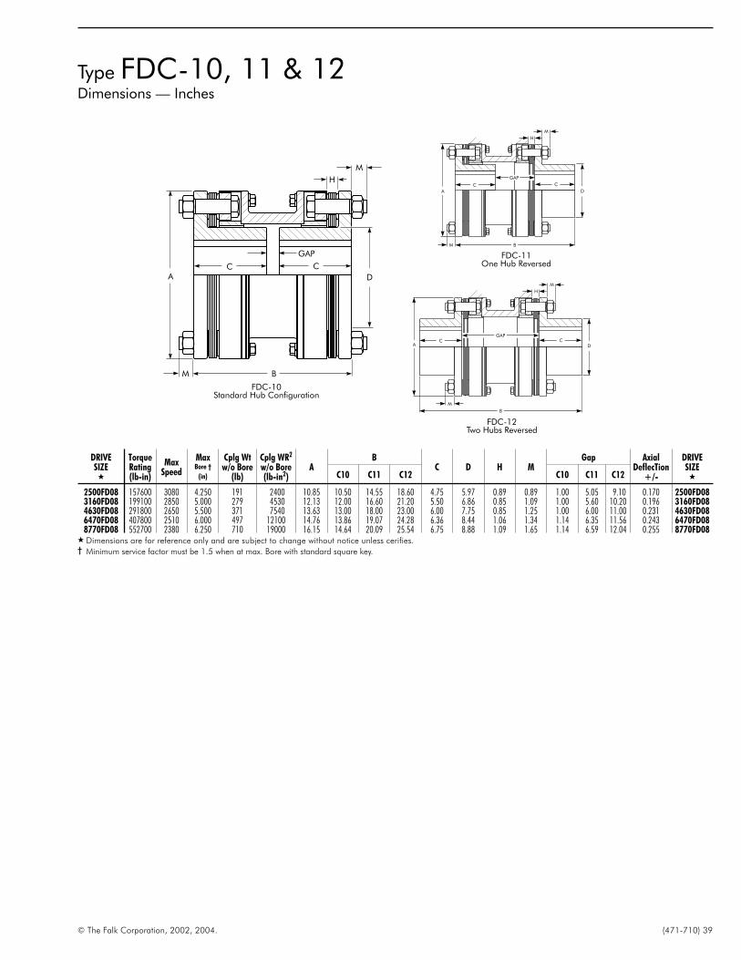
Type FDC-10, 11 & 12Dimensions — Inches
© The Falk Corporation, 2002, 2004. (471-710) 39
H
GAP
M
M
CC
D
B
A
FDC-10Standard Hub Configuration
H
M
M
CC
D
B
A
FDC-11One Hub Reversed
GAP
H
M
M
CCD
B
A
FDC-12Two Hubs Reversed
GAP
DRIVESIZE
�
TorqueRating(lb-in)
MaxSpeed
MaxBore †
(in)
Cplg Wtw/o Bore
(lb)
Cplg WR2
w/o Bore(lb-in2)
AB
C D H MGap Axial
DeflecTion+/-
DRIVESIZE
�C10 C11 C12 C10 C11 C12
2500FD08 157600 3080 4.250 191 2400 10.85 10.50 14.55 18.60 4.75 5.97 0.89 0.89 1.00 5.05 9.10 0.170 2500FD083160FD08 199100 2850 5.000 279 4530 12.13 12.00 16.60 21.20 5.50 6.86 0.85 1.09 1.00 5.60 10.20 0.196 3160FD084630FD08 291800 2650 5.500 371 7540 13.63 13.00 18.00 23.00 6.00 7.75 0.85 1.25 1.00 6.00 11.00 0.231 4630FD086470FD08 407800 2510 6.000 497 12100 14.76 13.86 19.07 24.28 6.36 8.44 1.06 1.34 1.14 6.35 11.56 0.243 6470FD088770FD08 552700 2380 6.250 710 19000 16.15 14.64 20.09 25.54 6.75 8.88 1.09 1.65 1.14 6.59 12.04 0.255 8770FD08
� Dimensions are for reference only and are subject to change without notice unless cerifies.† Minimum service factor must be 1.5 when at max. Bore with standard square key.

Type FD-A51, A52Gear to Disc Retrofit Assemblies/Dimensions — Inches
40 (471-710) © The Falk Corporation, 2002, 2003.
F A L K
A
A
D
D
BC
BC
CCC PLATE ADAPTER
RIGIDCOUPLINGHUB
BE
TYPE A51 SHROUDED BOLTS
SPOOLADAPTERCC C
F
SD
SD
SOLID SHAFT DESIGN�
GEAR CPLG SIZE FALKDISCCPLGSIZE
�
AssyTorqueRating †
(lb-in)
N-Hub Bore �
AdapterStyle
A
BE Min
C
CC
D(Ref)Falk
IndustryDesignation
MaxRecom
KeyMin
A51Shrouded
Bolt
A52Exposed
Bolt
A51Shrouded
Bolt
A52Exposed
Bolt
1040G 42500FD08 157,600 5.000 2.50 Spool 12.75 25.50 26.50 5.00 7.715 8.545 12.5003160FD08 199,100 6.000 2.75 Spool 12.75 27.30 28.40 5.75 7.871 8.411 12.5004630FD08 270,900 ‡ 6.875 3.00 Spool 12.75 29.20 32.20 6.50 8.091 9.591 12.500
1045G 4 ½
2500FD08 157,600 5.000 2.50 Spool 14.00 25.50 26.50 5.00 7.715 8.245 13.6253160FD08 199,100 6.000 2.75 Spool 14.00 27.30 28.40 5.75 7.871 8.401 13.6254630FD08 291,800 6.875 3.00 Spool 14.00 29.20 30.30 6.50 8.091 8.631 13.6256470FD08 371,700 ‡ 7.500 3.50 Spool 14.00 31.70 32.80 6.75 9.080 9.610 13.625
1050G 5
2500FD08 157,600 5.000 2.50 Plate 15.69 15.00 15.00 5.00 2.405 2.405 15.3133160FD08 199,100 6.000 2.75 Spool 15.69 28.60 29.60 5.75 8.501 9.041 15.3134630FD08 291,800 6.875 3.00 Spool 15.69 30.50 31.60 6.50 8.731 9.270 15.3136470FD08 407,800 7.500 3.50 Spool 15.69 32.70 34.00 6.75 9.600 10.250 15.3138770FD08 500,900 ‡ 8.250 4.00 Spool 15.69 34.90 36.20 7.50 9.915 10.565 15.313
� Dimensions are for reference only and are subject to change without notice unless certified.† Maximum operating speed of floating shaft assemblies is dependent on the lateral critical speed of the shaft. See floating shaft table on Page 34 for maximum BE’s at various
speeds.‡ Rated by gear coupling rigid hubs and bolts.� Hubs are furnished for interference fit per Table 25 on Page 51 unless otherwise specified.� Shaft design must be specified on order. For dimensions SD and OD, see table on bottom of Pages 36 & 37.

© The Falk Corporation, 2002, 2004. (471-710) 41
A D
D
BC
BC
CC PLATE ADAPTER
RIGIDCOUPLINGHUB
BE
TYPE A51 SHROUDED BOLTS
SPOOLADAPTERCC
FA
OD
OD
WELDED TUBE SHAFT DESIGN�
Gear Cplg Disc Cplg � FALKDISCCPLGSIZE
�
GEAR CPLG SIZE
A51 A52
F
A51 A52Industry
DesignationFalk
BCBolts
BCBolts
Wt (lb) WR2 Wt (lb)WR2
(lb-in2)Qty Dia — UNC Qty Dia — UNC
10.625 14 .625-11 11.000 8 .750-10 10.85 140 1,730 145 1,870 2500FD084 1040G10.625 14 .625-11 11.000 8 .750-10 12.13 190 2,690 195 2,830 3160FD08
10.625 14 .625-11 11.000 8 .750-10 13.63 250 4,220 260 4,420 4630FD08
11.750 14 .625-11 12.000 10 .750-10 10.85 145 2,040 155 2,240 2500FD08
4 ½ 1045G11.750 14 .625-11 12.000 10 .750-10 12.13 195 3,010 205 3,210 3160FD0811.750 14 .625-11 12.000 10 .750-10 13.63 255 4,540 260 4,750 4630FD0811.750 14 .625-11 12.000 10 .875-9 14.76 315 6,480 325 6,700 6470FD08
13.188 14 .750-10 13.500 8 .875-9 10.85 125 2,640 125 2,640 2500FD08
5 1050G13.188 14 .750-10 13.500 8 .875-9 12.13 220 4,000 240 4,550 3160FD0813.188 14 .750-10 13.500 8 .875-9 13.63 280 5,540 295 6,080 4630FD0813.188 14 .750-10 13.500 8 .875-9 14.76 340 7,480 360 8,060 6470FD0813.188 14 .750-10 13.500 8 .875-9 16.15 430 10,550 450 11,150 8770FD08
� Dimensions are for reference only and are subject to change without notice unless certified.�Weight and WR2 values include an adapter, one disc pack, one N-hub (no bore) and hardware.� Shaft design must be specified on order. For dimensions SD and OD, see table on bottom of Pages 36 & 37.

Coupling Application Data Sheet
Company _____________________________________________Address _____________________________________________
__________________________________________________________________________________________
Date ________________________________________________Phone ________________________________________________Fax ________________________________________________Response Req’d By _______________________________________Submitted By ____________________________________________
42 (471-710) © The Falk Corporation, 2002, 2004.
F A L K
SKETCH AREA
COUPLING DESIGN:Disc � Grid � Gear � Elastomer �
Horizontally Mounted � Vertically Mounted �
COUPLING TYPE:Close Coupled � Spacer � Other
SECTION I — PRIME MOVER:Type: Electric Motor �
Rating (hp, kW) ___________________
Engine � (No. of Cyl.) _______________Diesel � Gasoline � Gas �
Base Speed (rpm) ___________________
Turbine �
Steam � Air � Gas �
Maximum Speed (rpm) _______________
SECTION II — APPLICATION DATADescription
Duty Cycle: Continuous � Intermittent �
Load Characteristics:Unidirectional � Reversing �
Smooth � Light Shock � Heavy Shock �
Little Vibration � Med. Vibration � Hvy. Vibration �
Environmental Concerns (Temperature, Moisture, Dust, Corrosive Materials) _____________________________________________________________________________________________________________________________________________________________________
SECTION III — COUPLING SELECTION DATA
hp/bhp/kW ________________Torque _____________________
Coupling Speed ____________rpm
Distance Between Shaft Ends or Shaft Gap _________________
Driver Shaft Diameter _______Key ________________________
Fit: Clearance � Interference � Other _______________
Driven Shaft Diameter ______ Key ________________________
Fit: Clearance � Interference � Other _______________
Specifications Applicable:
API-610 � API-671 � Others ______________________
Service Factor:
AGMA Recommended � Other _______________________
Competitive Data:
Make _________________________________________________
Size & Type ____________________________________________
Bores _____________________ & _________________________
Price _____________________
Additional Comments: __________________________________
_______________________________________________________
_______________________________________________________
_______________________________________________________
_______________________________________________________
Design Requirements: Balance Class _______________________
Weight ____________________WR2 ________________________
Stiffness ___________________
Misalignment:
Angular ___________________Offset_______________________
Axial _____________________

Engineering Data — FDG, FDP & FD
© The Falk Corporation, 2002, 2004. (471-710) 43
MILLIMETERS (Per ISO R773 Standard)
6 8 2 x 2 38 44 12 x 8 95 110 28 x 16 260 290 63 x 328 10 3 x 3 44 50 14 x 9 110 130 32 x 18 290 330 70 x 36
10 12 4 x 4 50 58 16 x 10 130 150 36 x 20 330 380 80 x 4012 17 5 x 5 58 65 18 x 11 150 170 40 x 22 380 440 90 x 4517 22 6 x 6 65 75 20 x 12 170 200 45 x 25 440 500 100 x 5022 30 8 x 7 75 85 22 x 14 200 230 50 x 28 . . . . . . . . .30 38 10 x 8 85 95 25 x 14 230 260 56 x 32 . . . . . . . . .
50 HERTZ METRIC MOTORS (kW)
Frame Size 80 90S 90L 100L 112M 132S 132M 160M 160L 180M 180L 200M/L 225S 225M 250S 250M 280S 280M
Shaft Dia 19 24 24 28 28 38 38 42 42 48 48 555560
5560
60, 6570
60, 6570
65, 7580
65, 7580
3000 RPM0,751,10 1,5 2,2 3,0 4
5,57,5
1115
18,5 223037
45 45 555575
7590
90110
1500 RPM0,550,75 1,1 1,5
2,23,0
4 5,5 7,5 11 15 18,5 22 303745
45 555575
7590
90110
1000 RPM0,370,55 0,75 1,1 1,5 2,2 3
45,5
7,5 11 1518,522
30 30 373745
4550
5575
750 RPM0,180,25 0,37 0,55
0,751,1
1,5 2,2 34
5,57,5 11 15 18,5 22 30
3037
3745
4555
TABLE 6 — Recommended Commercial Keys for Bores with One Key — Inches & Millimeters
INCHES (Per ANSI B17.1 Standard)
Shaft DiaKey
Shaft DiaKey
Shaft DiaKey
Shaft DiaKey
Over Through Over Through Over Through Over Through
.438 .562 .125 x .125 1.750 2.250 .500 x .500 4.500 5.500 1.250 x 1.250 11.000 13.000 3.000 x 2.000
.562 .875 .188 x .188 2.250 2.750 .625 x .625 5.500 6.500 1.500 x 1.500 13.000 15.000 3.500 x 2.500
.875 1.250 .250 x .250 2.750 3.250 .750 x .750 6.500 7.500 1.750 x 1.500 15.000 18.000 4.000 x 3.0001.250 1.375 .312 x .312 3.250 3.750 .875 x .875 7.500 9.000 2.000 x 1.500 . . . . . . . . .1.375 1.750 .375 x .375 3.750 4.500 1.000 x 1.000 9.000 11.000 2.500 x 1.750 . . . . . . . . .
TABLE 7 — Shaft Diameters & Ratings for NEMA 60 Hertz & 50 Hertz Metric Motors
NEMA 60 HERTZ MOTORS (hp)
Frame SizeT Frames TS Frames
143 145 182 184 213 215 254 256 284 286 324 326 364 365 404 405 444 445 284 286 324 326 364 365 404 405 444 445
Shaft Dia .88 .88 1.13 1.13 1.38 1.38 1.63 1.63 1.88 1.88 2.13 2.13 2.38 2.38 2.88 2.88 3.38 3.38 1.63 1.63 1.88 1.88 1.88 1.88 2.13 2.13 2.38 2.38
3600 RPMDrip Proof 1 1/2 2-3 5 7 1/2 10 15 20 25 30 40 50 60 75 100 125 150 200 250 30 40 50 60 75 100 125 150 200 250
Enclosed 1 1/2 2 3 5 7 1/2 10 15 20 25 30 40 50 60 75 . . . 100 125 150 25 30 40 50 60 75 . . . 100 125 150
1800 RPMDrip Proof 1 1 1/2-2 3 5 7 1/2 10 15 20 25 30 40 50 60 75 100 125 150 200 25 30 40 50 60 75 100 125 150 200
Enclosed 1 1 1/2-2 3 5 7 1/2 10 15 20 25 30 40 50 60 75 . . . 100 125 150 25 30 40 50 60 75 . . . 100 125 150
1200 RPMDrip Proof& Enclosed
3/4 1 1 1/2 2 3 5 7 1/2 10 15 20 25 30 40 50 60 75 100 125 15 20 25 30 40 50 60 75 100 125
900 RPMDrip Proof& Enclosed
1/2 3/4 1 1 1/2 2 3 5 7 1/2 10 15 20 25 30 40 50 60 75 100 10 15 20 25 30 40 50 60 75 100

Engineering Data — FDG & FDP
44 (471-710) © The Falk Corporation, 2002, 2004.
F A L K
Y — SHAFTX — HUB
CHECK KEY STRESSES
W
OVERHANGING HUBS — Hubs may beoverhung on the shafting provided there is morethan one shaft diameter of hub/shaft engagementfor clearance fits or more than 0.75 times shaftdiameter hub/shaft engagement for interferencefits. If hub engagement is less than what isrequired, long hubs must be used as follows:
FDG: Reverse hubs or consult FalkCAUTION: The effect of open keyways oncoupling balance should always be considered.
Dimension L must be equal toor greater than Dimension SDfor clearance fits, or greaterthan Dimension SD times .75for interference fits.
Example: SD = 4"; then L mustbe 4" or more for clearance fitsor 3" or more for interferencefits.
SD SD
L L
TABLE 9 — Type FDG/FDP A-Hub Maximum Bores — Inches & Millimeters
SIZE
INCHES MILLIMETERS — Fits Per Table 27
With One Square Key With One Rectangular Key Max Bore Max Bore
StdBore
Fits PerTable 27
Int Fit w/Setscrew
OverKeyway
MaxBore
Y=XMaxBore
Y=X †
MaxBore
Y=W/2 ‡ Int Fit w/Setscrew
OverKeyway
With StdPullerBolt
Holes
With APIPuller Bolt
HolesW X W X W X
20FDG/P 1.625 .375 .188 1.750 .375 .125 1.750 .375 .062 1.500 1.625 1.625 45 3930FDG/P 2.000 .500 .250 2.000 .500 .188 2.125 .500 .125 1.750 2.000 2.000 50 4640FDG/P 2.250 .500 .250 2.375 .625 .219 2.500 .625 .125 2.125 2.250 2.250 60 5450FDG/P 2.750 .625 .312 2.750 .625 .219 3.000 .750 .125 2.500 2.750 2.750 75 6460FDG/P 3.250 .750 .375 3.250 .750 .250 3.375 .875 .187 3.000 3.250 3.250 90 7470FDG/P 3.625 .875 .438 3.750 .875 .312 3.875 1.000 .250 3.500 3.625 3.625 100 88
80FDG 3.500 .875 .438 3.750 .875 .312 3.875 1.000 .250 3.375 3.500 3.500 95 8590FDG 4.000 1.000 .500 4.250 1.000 .375 4.500 1.000 .250 3.750 4.000 4.000 110 97
100FDG 4.500 1.000 .500 4.750 1.250 .438 5.000 1.250 .250 4.250 4.500 4.500 121 108110FDG 5.000 1.250 .625 5.375 1.250 .438 5.625 1.500 .250 4.625 5.000 5.000 137 117
85FDP 5.000 1.250 .625 5.250 1.250 .438 5.750 1.500 .250 4.500 5.000 5.000 125 11695FDP 5.250 1.250 .625 5.500 1.500 .500 6.000 1.500 .250 5.000 5.250 5.250 135 126
105FDP 6.000 1.500 .750 6.500 1.500 .500 6.500 1.500 .250 5.625 6.000 6.000 155 143115FDP 6.500 1.500 .750 7.000 1.750 .750
For Bores Over 6.5”, Y=X6.125 6.500 6.500 170 156
125FDP 7.500 1.750 .750 8.000 2.000 .750 7.000 7.500 7.500 190 180† Square keys are standard for bores 6.500" and smaller.‡ Rectangular key in square key shaft key seat.
Shaded areas indicate maximum bores using standard recommended keys shown in Table 6, Page 43.
TABLE 8 — Type FDG/FDP N-Hub Maximum Bores — Inches & Millimeters
SIZE
INCHES MILLIMETERS — Fits Per Table 27
With One Square Key With One Rectangular Key Max Bore Max Bore
StdBore
Fits PerTable 27
Int Fit w/Setscrew
OverKeyway
MaxBore
Y=XMaxBore
Y=X †
MaxBore
Y=W/2 ‡ Int Fit w/Setscrew
OverKeyway
With StdPuller Bolt
Holes
With APIPuller Bolt
HolesW X W X W X
20FDG/P 1.625 .375 .188 1.750 .375 .125 1.750 .375 .062 1.500 1 .625 1.625 45 3930FDG/P 2.000 .500 .250 2.000 .500 .188 2.125 .500 .125 1.750 2.000 2.000 50 4640FDG/P 2.250 .500 .250 2.375 .625 .219 2.500 .625 .125 2.125 2.250 2.250 60 5450FDG/P 2.750 .625 .312 2.750 .625 .219 3.000 .750 .125 2.500 2.750 2.750 75 6460FDG/P 3.250 .750 .375 3.250 .750 .250 3.375 .875 .187 3.000 3.250 3.250 90 7470FDG/P 3.625 .875 .438 3.750 .875 .312 3.875 1.000 .250 3.500 3.625 3.625 100 88
80FDG 3.500 .875 .438 3.750 .875 .312 3.875 1.000 .250 3.375 3.500 3.500 95 8590FDG 4.000 1.000 .500 4.250 1.000 .375 4.500 1.000 .250 3.750 4.000 4.000 110 97
100FDG 4.500 1.000 .500 4.750 1.250 .438 5.000 1.250 .250 4.250 4.500 4.500 121 108110FDG 5.000 1.250 .625 5.375 1.250 .438 5.625 1.500 .250 4.625 5.000 5.000 137 117
85FDP 4.250 1.000 .500 4.375 1.000 .375 4.500 1.250 .250 4.000 4.250 4.250 105 10195FDP 4.625 1.250 .625 4.750 1.250 .438 4.875 1.250 .250 4.500 4.625 4.625 120 114
105FDP 5.250 1.250 .625 5.375 1.250 .438 5.750 1.500 .250 5.000 5.250 5.250 135 126115FDP 5.875 1.500 .750 6.000 1.500 .500 6.250 1.500 .250 5.500 5.875 5.875 150 141125FDP 6.875 1.750 .875 7.000 1.750 .750 For Bores Over 6.5”, Y=X 6.500 6.875 6.875 175 163
† Square keys are standard for bores 6.500" and smaller.‡ Rectangular key in square key shaft key seat.
Shaded areas indicate maximum bores using standard recommended keys shown in Table 6, Page 43.

Engineering Data — FDG & FDP
© The Falk Corporation, 2002, 2004. (471-710) 45
TABLE 10 — Type FDG/FDP C & D-Hub Maximum Bores — Inches & Millimeters
SIZE
INCHES MILLIMETERS — Fits Per Table 27
With One Square Key With One Rectangular Key Max Bore Max Bore
MaxBore
Y=XMaxBore
Y=X †
MaxBore
Y=W/2 ‡ Int Fit w/Setscrew
OverKeyway
With StdPuller Bolt
Holes
With APIPuller Bolt
Holes
StdBore
Fits PerTable 27
Int Fitw/Setscrew
OverKeyway
W X W X W X
20FDG/P 1.125 .250 .125 1.188 .250 .094 1.250 .250 .062 1.000 1.125 . . . 28 2630FDG/P 1.625 .375 .188 1.750 .375 .125 1.750 .375 .062 1.500 1.625 1.625 43 3940FDG/P 1.875 .500 .250 2.000 .500 .188 2.125 .500 .125 1.750 1.875 1.875 50 4650FDG/P 2.250 .500 .250 2.375 .625 .219 2.500 .625 .125 2.125 2.250 2.250 60 5460FDG/P 2.625 .625 .313 2.750 .625 .219 3.000 .750 .125 2.500 2.625 2.625 70 6470FDG/P 3.000 .750 .375 3.250 .750 .250 3.375 .875 .187 2.875 3.000 3.000 82 74
80FDG 3.500 .875 .438 3.750 .875 .312 3.875 1.000 .250 3.375 3.500 3.500 95 8590FDG 4.000 1.000 .500 4.250 1.000 .375 4.500 1.000 .250 3.750 4.000 4.000 110 97
100FDG 4.500 1.000 .500 4.750 1.250 .438 5.000 1.250 .250 4.250 4.500 4.500 121 108110FDG 5.000 1.250 .625 5.375 1.250 .438 5.625 1.500 .250 4.625 5.000 5.000 137 117
85FDP 3.500 .875 .438 3.625 1.000 .375 3.750 1.000 .250 3.250 3.500 3.500 95 8395FDP 4.000 1.000 .500 4.125 1.000 .375 4.375 1.000 .250 4.000 4.000 4.000 110 100
105FDP 4.500 1.000 .500 4.750 1.250 .438 5.000 1.250 .250 4.250 4.500 4.500 120 109115FDP 5.000 1.250 .625 5.250 1.250 .438 5.750 1.500 .250 4.750 5.000 5.000 140 120125FDP 6.000 1.500 .750 6.500 1.500 .500 6.500 1.500 .250 5.500 6.000 6.000 165 142
† Square keys are standard for bores 6.500" and smaller.‡ Rectangular key in square key shaft key seat.
Shaded areas indicate maximum bores using standard recommended keys shown in Table 6, Page 43.
TABLE 11 — Type FDG/FDP L-Hub Maximum Bores — Inches & Millimeters
SIZE
INCHES MILLIMETERS — Fits Per Table 27
With One Square Key With One Rectangular Key Max Bore Max. Bore
MaxBore
Y=XMaxBore
Y=X †
MaxBore
Y=W/2 ‡ Int Fit w/Setscrew
OverKeyway
With StdPuller Bolt
Holes
With APIPuller Bolt
Holes
StdBore
Fits PerTable 27
Int Fitw/Setscrew
OverKeyway
W X W X W X
20FDG/P 2.250 .625 .375 2.500 .625 .125 2.750 .750 .125 2.250 2.250 2.250 60 5830FDG/P 2.750 .625 .375 2.875 .750 .125 3.250 .750 .125 2.625 2.750 2.750 70 6840FDG/P 3.375 .875 .438 3.500 .875 .187 3.875 1.000 .250 3.250 3.375 3.375 80 8250FDG/P 4.125 1.000 .500 4.125 1.000 .250 4.500 1.000 .250 3.875 4.250 4.250 100 9860FDG/P 4.625 1.250 .625 4.750 1.250 .250 5.375 1.250 .250 4.250 4.625 4.625 110 11070FDG/P 5.250 1.250 .625 5.500 1.250 .250 6.125 1.500 .250 5.000 5.250 5.250 130 128
80FDG 6.000 1.500 .750 6.500 1.500 .500 6.500 1.500 .250 5.750 6.000 6.000 150 14591FDG 6.750 1.750 .875 7.000 1.750 .750
For Bores Over 6.5”, Y=X
6.375 6.750 6.750 170 160100FDG 7.250 1.750 .875 7.500 1.750 .750 6.750 7.250 7.250 180 170110FDG 8.500 2.000 1.000 8.750 2.000 .750 8.000 8.500 8.500 215 200
85FDP 6.250 1.500 .750 6.500 1.500 .500 6.500 1.500 .500 5.875 6.250 6.250 160 14995FDP 6.750 1.750 .750 6.875 1.750 .750
For Bores Over 6.5”, Y=X
6.375 6.750 6.750 174 162105FDP 7.500 1.750 .750 8.000 2.000 .750 7.000 7.500 7.500 195 182115FDP 8.500 2.000 .750 9.000 2.000 .750 7.750 8.500 8.500 216 202125FDP 9.500 2.500 .875 10.000 2.500 .875 9.000 9.500 9.500 242 226
† Square keys are standard for bores 6.500" and smaller.‡ Rectangular key in square key shaft key seat.
Shaded areas indicate maximum bores using standard recommended keys shown in Table 6, Page 43.

Engineering Data — FDG & FDP
46 (471-710) © The Falk Corporation, 2002, 2004.
F A L K
TABLE 15 — FDG/FDP Angular MisalignmentCapacity �
Installation Operational Design
.1° .25° .5°� Degrees listed are per disc pack.
TABLE 14 — FDG/FDP API 610 Puller BoltHoles – Inches
SIZE
N-Hub A-Hub ‡ C-Hub
BoltCircle
TapSize †
MaxBore
BoltCircle
TapSize †
MaxBore
BoltCircle
TapSize †
MaxBore
30 3.47 .375-16 1.125 3.47 .375-16 2.000 1.86 .375-16 1.62540 4.26 .375-16 1.625 4.26 .375-16 2.250 2.13 .375-16 1.87550 5.12 .375-16 2.250 5.12 .375-16 2.750 2.60 .375-16 2.25060 5.79 .375-16 2.938 5.79 .375-16 3.250 3.04 .375-16 2.62570 6.70 .375-16 3.625 6.70 .375-16 3.625 3.63 .375-16 3.000
80 7.52 .375-16 3.500 7.52 .375-16 3.500 7.52 .375-16 3.50090 8.50 .375-16 4.000 8.50 .375-16 4.000 8.50 .375-16 4.000
100 9.05 .375-16 4.500 9.05 .375-16 4.500 9.05 .375-16 4.500110 10.51 .375-16 5.000 10.51 .375-16 5.000 10.51 .375-16 5.000
85 7.80 .375-16 4.000 7.80 .375-16 5.000 4.14 .375-16 3.50095 8.59 .375-16 4.750 8.59 .375-16 5.250 5.12 .375-16 4.000
105 9.61 .375-16 5.125 9.61 .375-16 6.000 5.67 .375-16 4.500115 10.67 .375-16 5.750 10.67 .375-16 6.500 6.15 .375-16 5.000125 11.93 .375-16 6.875 11.93 .375-16 7.500 9.37 .375-16 6.000
† Drill and tap thru flange between existing holes.‡ Metric puller holes meeting API610 are standard and included with A hubs.
TABLE 12 — FDG Coupling Factors & SpacerFactors for Torsional Stiffness(x 106 lb-in/Radian)
SIZE
Coupling Factor (CF) SpacerFactor(DF)
N10, A10,L10, H10
30NN 31AA 30LL 30AL 10CC 11CC 12CC 20NN 20AN
20 0.391 0.404 0.416 0.409 0.347 0.337 0.327 0.731 0.726 7.330 1.205 1.221 1.287 1.253 1.097 1.074 1.052 2.224 2.198 33.340 2.200 2.216 2.367 2.289 1.966 1.919 1.875 4.066 3.966 60.0
50 4.098 4.182 4.473 4.322 3.650 3.548 3.451 7.488 7.386 128.660 6.478 6.723 7.136 6.923 5.754 5.592 5.439 11.695 11.637 207.070 9.992 10.156 10.925 10.527 9.071 8.833 8.608 18.029 17.705 411.1
80 12.054 12.587 14.021 13.265 11.646 11.554 11.464 20.882 20.771 411.190 17.737 18.933 21.175 19.991 16.903 16.785 16.670 30.430 30.272 411.1
100 22.006 23.408 25.526 24.421 20.968 20.819 20.671 38.463 38.294 680.0
Calculate Coupling Assembly Torsional Stiffness as Follows:
Where:KA = Torsional Stiffness of Coupling AssemblyCF = Coupling FactorDF = Spacer FactorBE = Distance Between Shaft Ends
KH1 & KH2 = See 1/3 Penetration Effect below.
1/3 Shaft Penetration Effect
KH =(Bore
Hub Length
4
( . ))
116 1036
x
x
KH1 uses bore and hub length for one hubKH2 uses bore and hub length for other hub
Types 30 & 31
KA =1
1
KH KH CF
BE
DF1 2
� � �1 1
Types 10, 11, 12 & 20
KA =1
1
KH KH
1
CF1 2
� �1
TABLE 13 — FDP Coupling Factors & SpacerFactors for Torsional Stiffness(x 106 lb-in/Radian)
SIZE
Coupling Factor (CF) SpacerFactor(DF)
30 & 3130NN 31AA 30LL 30AL 10CC 11CC 12CC 20NN 20AN
20 0.972 1.052 1.138 1.093 0.739 0.695 0.655 1.657 1.632 7.330 2.615 2.691 3.031 2.851 2.152 2.065 1.985 4.422 4.322 33.340 8.798 9.057 12.266 10.420 5.958 5.550 5.194 13.251 12.238 60.0
50 11.833 12.563 15.608 13.921 8.738 8.174 7.679 18.588 17.976 128.660 16.621 18.334 21.776 19.908 12.567 11.818 11.153 26.037 25.754 207.070 32.607 34.415 45.202 39.078 24.487 22.830 21.383 48.162 45.919 411.1
85 104.442 178.505 197.325 187.444 55.092 48.782 43.770 129.570 143.940 680.095 135.867 201.303 228.947 214.237 86.934 78.003 70.737 175.102 188.485 1269.6
105 189.574 309.259 348.688 327.792 119.593 106.812 96.498 234.417 258.634 1742.6115 291.607 494.219 608.767 545.545 163.395 143.466 127.870 345.544 375.407 2540.1125 343.477 496.292 536.894 515.795 235.597 212.606 193.703 457.369 495.589 4576.0
TABLE 14A — FDG/FDP Standard Puller BoltHoles – Metric
SIZE
N-Hub A-Hub ‡ C-Hub
BoltCircle
TapSize
MaxBore
BoltCircle
TapSize
MaxBore
BoltCircle
TapSize
MaxBore
20 74 M6-1.0-6H 45 74 M5-0.8-6H 45 28 M6-1.0-6H 2830 88 M10-1.5-6H 50 88 M10-1.5-6H 50 47 M6-1.0-6H 4340 108 M10-1.5-6H 60 108 M10-1.5-6H 60 54 M10-1.5-6H 5050 130 M10-1.5-6H 75 130 M10-1.5-6H 75 66 M10-1.5-6H 6060 147 M10-1.5-6H 90 147 M10-1.5-6H 90 77 M10-1.5-6H 7070 170 M10-1.5-6H 100 170 M10-1.5-6H 100 92 M10-1.5-6H 82
80 191 M12-1.75-6H 95 191 M12-1.75-6H 95 191 M12-1.75-6H 9590 216 M14-2.0-6H 110 216 M14-2.0-6H 110 216 M14-2.0-6H 110
100 230 M16-2.0-6H 121 230 M16-2.0-6H 121 230 M16-2.0-6H 121110 267 M16-2.0-6H 137 267 M16-2.0-6H 137 267 M16-2.0-6H 137
85 198 M12-1.75-6H 105 198 M12-1.75-6H 125 105 M10-1.5-6H 9595 218 M12-1.75-6H 120 218 M12-1.75-6H 135 130 M10-1.5-6H 110
105 244 M14-2.0-6H 135 244 M14-2.0-6H 155 144 M10-1.5-6H 120115 271 M16-2.0-6H 150 271 M16-2.0-6H 170 156 M12-1.75-6H 140125 303 M16-2.0-6H 175 303 M16-2.0-6H 190 190 M12-1.75-6H 165
‡ Metric puller holes are standard and included with A hubs.Shaded sizes don’t meet API 610 standards.

Engineering Data — FDG & FDP
© The Falk Corporation, 2002, 2004. (471-710) 47
TABLE 16 — Taper-Lock® Bushings for Type FDG A, N & C Hubs
SIZE
A Hub N Hub C Hub
Taper-Lock® BushingL
(Inches)
Taper-Lock® BushingL
(Inches)
Taper-Lock® BushingL
(Inches)BushingNumber
Bore Range(inches)
Torque(lb·in)
BushingNumber
Bore Range(inches)
Torque(lb·in)
BushingNumber
Bore Range(inches)
Torque(lb·in)
20 1108 0.500 to 1.125 840
REFERTO
FALK
1108 0.500 to 1.125 840
REFERTO
FALK
. . . . . . . . . . . .30 1215 0.500 to 1.250 1550 1108 0.500 to 1.125 1300 1108 0.500 to 1.125 1300
REFERTO
FALK
40 1615 0.500 to 1.625 2740 1215 0.500 to 1.250 2740 1215 0.500 to 1.250 2740
50 2012 0.500 to 2.000 5090 1615 0.500 to 1.625 4300 1615 0.500 to 1.625 430060 2525 0.750 to 2.500 7740 2012 0.500 to 2.000 7150 2012 0.500 to 2.000 715070 2525 0.750 to 2.500 11300 2525 0.750 to 2.500 11300 2525 0.750 to 2.500 11300
80 2525 0.750 to 2.500 11300 2525 0.750 to 2.500 11300 2525 0.750 to 2.500 1130090 3030 0.938 to 3.000 23000 3030 0.938 to 3.000 23000 3030 0.938 to 3.000 23000
100 3535 1.188 to 3.500 33800 3535 1.188 to 3.500 33800 3535 1.188 to 3.500 33800110 3535 1.188 to 3.500 44000 3535 1.188 to 3.500 44000 3535 1.188 to 3.500 44000
TABLE 17 — Taper-Lock® Bushings for Type FDP A, N & C Hubs
SIZE
A Hub
L(Inches)
N Hub
L(Inches)
C Hub
L(Inches)
Taper-Lock® Bushing Taper-Lock® Bushing Taper-Lock® Bushing
BushingNumber
Bore Range(inches)
Torque(lb·in)
BushingNumber
Bore Range(inches)
Torque(lb·in)
BushingNumber
Bore Range(inches)
Torque(lb·in)
20 1108 0.500 to 1.125 1285
REFERTO
FALK
1108 0.500 to 1.125 1285
REFERTO
FALK
. . . . . . . . . . . .30 1215 0.500 to 1.250 2200 1108 0.500 to 1.125 1300 1108 0.500 to 1.125 1300
REFERTO
FALK
40 1615 0.500 to 1.625 4300 1215 0.500 to 1.250 2740 1215 0.500 to 1.250 3550
50 2012 0.500 to 2.000 7150 1615 0.500 to 1.625 4300 1615 0.500 to 1.625 430060 2525 0.750 to 2.500 11300 2012 0.500 to 2.000 7150 2012 0.500 to 2.000 715070 2525 0.750 to 2.500 11300 2525 0.750 to 2.500 11300 2525 0.750 to 2.500 11300
85 3535 1.188 to 3.500 44250 2525 0.750 to 2.500 11300 2525 0.750 to 2.500 1130095 4040 1.188 to 3.500 61950 3030 0.938 to 3.000 24000 3030 0.938 to 3.000 24000105 4545 1.938 to 4.500 84520 3535 1.188 to 3.500 44800 3535 1.188 to 3.500 44800115 5050 2.438 to 5.000 110200 3535 1.188 to 3.500 44800 3535 1.188 to 3.500 44800125 5050 2.438 to 5.000 126000 4545 1.938 to 4.500 110000 4545 1.938 to 4.500 110000
N HUB
LL
A HUB C HUB
L

Engineering Data — FD
48 (471-710) © The Falk Corporation, 2002, 2004.
F A L K
Y — SHAFTX — HUB
CHECK KEY STRESSES
W
OVERHANGING HUBS — Hubs may beoverhung on the shafting provided there is morethan one shaft diameter of hub/shaft engagementfor clearance fits or more than 0.75 times shaftdiameter hub/shaft engagement for interferencefits. If hub engagement is less than what isrequired, long hubs must be used as follows:
FD: See Table 20 on Page 49CAUTION: The effect of open keyways oncoupling balance should always be considered.
Dimension L must be equal toor greater than Dimension SDfor clearance fits, or greaterthan Dimension SD times .75for interference fits.
Example: SD = 4"; then L mustbe 4" or more for clearance fitsor 3" or more for interferencefits.
SD SD
L L
TABLE 18 — Type FD N-Hub Maximum Bores — Inches & Millimeters
SIZE
INCHES MILLIMETERS — Fits Per Table 20
With One Square Key With One Rectangular Key Max Bore
MinBore
Max Bore
MaxBore
Y=XMaxBore
Y=XMaxBore
Y=W/2 Int Fit w/Setscrew
OverKeyway
With StdPullerBolt
Holes
StdBore
Fits PerTable 20
Int Fitw/Setscrew
OverKeyway
WithPuller
Holes PerTable 16
W X W X W X
2500FD08 5.000 1.250 .625 5.250 1.250 .438 5.750 1.500 .250 4.750 5.000 64 140 120 1303160FD08 6.000 1.500 .750 6.500 1.500 .500 6.500 1.500 .250 5.375 6.000 70 165 140 150
4630FD08 6.625 1.750 .875 6.875 1.750 .750
For BoresOver
6.500"Y=X
6.000 6.875 77 190 160 1606470FD08 7.250 1.750 .875 7.500 1.750 .750 6.625 7.500 89 200 175 1808770FD08 7.750 2.000 1.000 8.250 2.000 .750 7.000 8.250 102 220 185 200
11000FD08 8.250 2.000 1.000 8.750 2.000 .750 . . . 8.100 115 230 195 195
13000FD08 9.750 2.500 1.250 10.500 2.500 .875 . . . 9.100 115 260 220 23014000FD10 8.000 2.000 1.000 8.500 2.000 .750 . . . . . . 115 225 195 19515300FD08 10.500 2.500 1.250 11.000 2.500 .875 . . . 10.000 127 290 240 26016800FD10 9.000 2.500 1.250 9.750 2.500 .875 . . . . . . 115 260 220 230
17200FD12 8.000 2.000 1.000 8.500 2.000 .750 . . . . . . 115 225 195 19518500FD08 11.000 2.500 1.250 11.500 3.000 1.000 . . . 10.375 127 305 255 26019700FD10 10.250 2.500 1.250 10.750 3.000 1.000 . . . . . . 127 285 240 26020000FD12 9.000 2.500 1.250 9.750 2.500 .875 . . . . . . 115 260 220 230
23800FD10 11.000 2.500 1.250 11.500 3.000 1.000 . . . . . . 127 305 255 26024000FD12 10.250 2.500 1.250 10.750 3.000 1.000 . . . . . . 127 285 240 26024000FD08 11.000 2.500 1.250 12.000 3.000 1.000 . . . 10.850 127 320 265 27528000FD08 12.000 3.000 1.500 13.000 3.000 1.000 . . . 11.375 127 340 275 290
29000FD12 11.000 2.500 1.250 11.500 3.000 1.000 . . . . . . 127 305 255 26031000FD10 11.000 2.500 1.250 11.500 3.000 1.000 . . . . . . 127 305 265 27536000FD10 12.000 3.000 1.500 12.750 3.000 1.000 . . . . . . 127 335 275 29537700FD12 11.000 2.500 1.250 11.500 3.000 1.000 . . . . . . 127 305 265 27544000FD12 12.000 3.000 1.500 12.750 3.000 1.000 . . . . . . 127 335 275 295
Shaded areas indicate maximum bores using standard recommended keys shown in Table 1, Page 41.
TABLE 19 — Type FD A-Hub Maximum Bores — Inches & Millimeters
SIZE
INCHES MILLIMETERS — Fits Per Table 20
With One Square Key With One Rectangular Key Max Bore
MinBore
Max. Bore
Int Fit w/Setscrew
OverKeyway
With StdPullerBolt
Holes
MaxBore
Y=XMaxBore
Y=XMaxBore
Y=W/2 StdBore
Fits PerTable 20
Int Fitw/Setscrew
OverKeyway
WithPuller
Holes PerTable 16
W X W X W X
2500FD08 5.875 1.500 .750 6.000 1.500 .500 6.000 1.500 .250 5.375 5.875 64 150 135 1503160FD08 7.000 1.750 .875 7.000 1.750 .750 . . . . . . . . . 6.375 7.000 70 180 160 170
4630FD08 7.750 2.000 1.000 8.000 2.000 .750
For BoresOver
6.500"Y=X
7.000 8.000 77 200 175 2006470FD08 8.750 2.000 1.000 8.750 2.000 .750 8.000 8.750 89 220 200 2158770FD08 9.500 2.500 1.250 9.625 2.500 .875 8.750 9.625 102 240 215 240
11000FD08 10.500 2.500 1.250 11.125 3.000 1.000 . . . 11.125 115 280 250 275
13000FD08 12.000 3.000 1.500 12.500 3.000 1.000 . . . 12.500 115 320 275 28015300FD08 13.500 3.500 1.750 13.875 3.500 1.250 . . . 13.875 127 340 300 28018500FD08 14.000 3.500 1.750 14.250 3.500 1.250 . . . 14.250 127 360 315 30024000FD08 14.000 3.500 1.750 14.250 3.500 1.250 . . . 14.250 127 360 320 31028000FD08 14.750 3.500 1.750 15.750 4.000 1.500 . . . 15.750 127 400 350 360

Engineering Data — FD
© The Falk Corporation, 2002, 2004. (471-710) 49
Calculate Coupling Assembly Torsional Stiffness as Follows:
Where:KA = Torsional Stiffness of Coupling AssemblyCF = Coupling FactorDF = Spacer FactorBE = Distance Between Shaft Ends
KH1 & KH2 = See 1/3 Penetration Effect below.
1/3 Shaft Penetration Effect
KH = (1.16 x 10³ x (Bore
Hub Length
64
))
KH1 uses bore and hub length for one hubKH2 uses bore and hub length for other hub
Types N10 & A10
KA =1
1
KH KH CF
BE
DF1 2
� � �1 1
Type M10
KA =1
1
KH KH 2 x CF 2 x CF
BE
DF1 2 (A10) (N10)
� � � �1 1 1
Types N20 & M20
KA =1
1
KH KH
1
CF1 2
� �1
TABLE 20 — FD Taper-Lock Bushing Selection �
SIZE
A-Hub N-HubSpeedrpm
BushingNumber
BoreRange †
(Inches)
Torque ‡
(lb–in)BushingNumber
BoreRange †
(Inches)
Torque ‡
(lb–in)
Max �A10, N10, &
M10
2500FD08 4040 1.438 - 4.000 77,300 3535 1.188 - 3.500 44,800 29003160FD08 5050 2.438 - 5.000 126,000 3535 1.188 - 3.500 44,800 27004630FD08 5050 2.438 - 5.000 126,000 4040 1.438 - 4.000 77,300 25006470FD08 5050 2.438 - 5.000 126,000 4545 1.938 - 4.500 110,000 2400
8770FD08 5050 2.438 - 5.000 126,000 5050 2.438 - 5.000 126,000 220011000FD08 8065 5.438 - 8.000 456,000 5050 2.438 - 5.000 126,000 200013000FD08 8065 5.438 - 8.000 456,000 5050 2.438 - 5.000 126,000 190015300FD08 8065 5.438 - 8.000 456,000 6050 4.438 - 6.000 282,000 1800
18500FD08 10085 7.000 - 10.000 869,000 7060 4.938 - 7.000 416,000 175024000FD08 10085 7.000 - 10.000 869,000 8065 5.438 - 8.000 456,000 170028000FD08 10085 7.000 - 10.000 869,000 8065 5.438 - 8.000 456,000 1650
� CAUTION: Cast iron bushings are not recommended for shock load, reversing load or any application whichrequires a 1.75 or higher service factor.
† The use of Taper-Lock bushings results in a smaller bore capacity than in straight bored hubs.‡ The use of Taper-Lock bushings results in a derating of most size couplings. The bushed coupling ratings are shown above.� Maximum rpm for floating shaft assemblies will be the same as the Type M20 or N20 or as listed for the floating shaft
assembly based on critical speed.
TABLE 21 — FD Coupling Factors & SpacerFactors for Torsional Stiffness(x 106 lb-in/Radian)
SIZECoupling Factor (CF) Spacer Factor
(DF)N10, A10 & M10N10 A10 N20 M20
2500FD08 –1140 –135 245 274 3843160FD08 –4630 –186 352 388 5814630FD08 1750 –409 497 538 11106470FD08 3200 –507 675 746 1720
8770FD08 2830 –610 824 912 236011000FD08 663 790 922 1112 399013000FD08 787 909 1213 1428 538015300FD08 909 1040 1516 1763 7070
18500FD08 1040 1170 1803 2303 987024000FD08 1400 1600 2180 2492 11,40028000FD08 1580 1820 2544 2990 14,400

Engineering Data — FD
50 (471-710) © The Falk Corporation, 2002, 2004.
F A L K
UHUG
Z
UH
UG
Z
P P
N-HUB A-HUB
TABLE 22 — FD Taper & Counterbore Limitations — Inches
SIZEN-Hub A-Hub
P Max ‡ UH Max UG Min Z Max P Max ‡ UH Max UG Min Z Max
2500FD 6.75 5.000 2.50 5.500 6.60 5.875 2.50 6.1203160FD 6.75 6.000 2.75 6.750 6.75 7.000 2.75 7.120
4630FD 6.75 6.875 3.00 7.625 7.40 8.000 3.00 8.1206470FD 7.40 7.500 3.50 8.250 7.50 8.750 3.75 9.0008770FD 7.50 � 8.250 4.00 8.750 7.58 � 9.625 4.00 9.620
‡ Standard long hub length.� Standard hub.
TABLE 23 — FD Puller Bolt Holes — Inches
SIZEA-Hub N-Hub
B.C. † Tap Size — UNC B.C. † Tap Size — UNC
2500FD08 7.250 .500-13 x 1.0 6.600 .375-16 x .753160FD08 8.600 .625-11 x 1.2 7.400 .500-13 x 1.0
4630FD08 9.750 .625-11 x 1.2 8.200 .625-11 x 1.26470FD08 10.750 .750-10 x 1.5 8.800 .625-11 x 1.28770FD08 11.750 .750-10 x 1.5 9.600 .625-11 x 1.2
† Locate Puller Bolt holes 90° from keyway.
TABLE 24 — FD Angular Misalignment Capacity �
No of Bolts Installation Operational Design
FD08 .12° .25° .50°FD10 .09° .18° .37°FD12 .06° .12° .25°
� Degrees listed are per disc pack.

Engineering Data
© The Falk Corporation, 2002, 2004. (471-710) 51
ShaftDia
Clearance Fit Interference Fit
HubBore
Clear-ance
HubBore
Inter-ference
+.0000 +.0010 .0000 +.0005 .0000– .0005 – .0000 .0015 – .0000 .0010
.5000 .5000 .4990
.5625 .5625 .5615
.6250 .6250 .6240
.6875 .6875 .6865
.7500 .7500 .7490
.8125 .8125 .8115
.8750 .8750 .8740
.9375 .9375 .9365
1.0000 1.0000 .99901.0625 1.0625 1.06151.1250 1.1250 1.12401.1875 1.1875 1.1865
1.2500 1.2500 1.24901.3125 1.3125 1.31151.3750 1.3750 1.37401.4375 1.4375 1.43651.5000 1.5000 1.4990
+.0000 +.0010 .0000 +.0005 .0000– .0010 – .0000 .0020 – .0000 .0015
1.5625 1.5625 1.56101.6250 1.6250 1.62351.6875 1.6875 1.68601.7500 1.7500 1.7485
1.8125 1.8125 1.81101.8750 1.8750 1.87351.9375 1.9375 1.93602.0000 2.0000 1.9985
+.0000 +.0015 .0000 +.0005 .0000– .0010 – .0000 .0025 – .0000 .0015
2.0625 2.0625 2.06102.1250 2.1250 2.12352.1875 2.1875 2.1860
ShaftDia
Clearance Fit Interference Fit
HubBore
Clear-ance
HubBore
Inter-ference
+.0000 +.0015 .0000 +.0010 .0000– .0010 – .0000 .0025 – .0000 .0020
2.2500 2.2500 2.24802.3125 2.3125 2.31052.3750 2.3750 2.37302.4375 2.4375 2.4355
2.5000 2.5000 2.49802.5625 2.5625 2.56052.6250 2.6250 2.62302.6875 2.6875 2.6855
2.7500 2.7500 2.74802.8125 2.8125 2.81052.8750 2.8750 2.87302.9375 2.9375 2.93553.0000 3.0000 2.9980
+.0000 +.0015 .0000 +.0010 .0005– .0010 – .0000 .0025 – .0000 .0025
3.0625 3.0625 3.06003.1250 3.1250 3.12253.1875 3.1875 3.18503.2500 3.2500 3.2475
3.3125 3.3125 3.31003.3750 3.3750 3.37253.4375 3.4375 3.43503.5000 3.5000 3.4975
3.5625 3.5625 3.56003.6250 3.6250 3.62253.6875 3.6875 3.68503.7500 3.7500 3.7475
3.8125 3.8125 3.81003.8750 3.8750 3.87253.9375 3.9375 3.93504.0000 4.0000 3.9975
� For shaft diameters larger than 17.000, use an average interference fit of .0005"per inch of shaft diameter with the following bore tolerances:+.0025, –.0000 for over 17 to 20 dia. incl.+.003, –.000 for over 20 to 30 dia. incl.+.004, –.000 for over 30 to 40 dia. incl.Tolerances and fits comply with, or are within, AGMA 9002-A86 standard (class1 clearance fit).
ShaftDia
Clearance Fit Interference Fit
HubBore
Clear-ance
HubBore
Inter-ference
+.0000 +.0015 .0000 +.0015 .0010– .0010 – .0000 .0025 – .0000 .0035
4.0625 4.0625 4.05904.1250 4.1250 4.12154.1875 4.1875 4.18404.2500 4.2500 4.2465
4.3125 4.3125 4.30904.3750 4.3750 4.37154.4375 4.4375 4.43404.5000 4.5000 4.4965
4.5625 4.5625 4.55904.6250 4.6250 4.62154.6875 4.6875 4.68404.7500 4.7500 4.7465
4.8125 4.8125 4.80904.8750 4.8750 4.87154.9375 4.9375 4.93405.0000 5.0000 4.9965
5.0625 5.0625 5.0585 .00155.1250 5.1250 5.1210 .00405.1875 5.1875 5.18355.2500 5.2500 5.2460
5.3125 5.3125 5.30855.3750 5.3750 5.37105.4375 5.4375 5.43355.5000 5.5000 5.4960
5.5625 5.5625 5.55855.6250 5.6250 5.62105.6875 5.6875 5.68355.7500 5.7500 5.7460
5.8125 5.8125 5.80855.8750 5.8750 5.87105.9375 5.9375 5.93356.0000 6.0000 5.9960
6.2500 6.2500 6.24606.5000 6.5000 6.4960
ShaftDia
Interference Fit
HubBore
Inter-ference
+.0000 +.0015 .0015– .0010 – .0000 .0040
6.7500 6.74607.0000 6.9960
+.0000 +.0020 .0020– .0010 – .0000 .0050
7.250 7.24507.500 7.49507.750 7.74508.000 7.9950
8.250 8.2445 .00258.500 8.4945 .00558.750 8.74459.000 8.9945
9.250 9.2440 .00309.500 9.4940 .00609.750 9.7440
10.000 9.9940
10.250 10.2435 .003510.500 10.4935 .006510.750 10.743511.000 10.9935
11.250 11.2430 .004011.500 11.4930 .007011.750 11.743012.000 11.9930
12.500 12.4925 .004513.000 12.9925 .0075
13.500 13.4920 .005014.000 13.9920 .0080
14.500 14.4915 .005515.000 14.9915 .0085
+.000 +.0025 .0055– .001 – .0000 .009015.500 15.491016.000 15.9910
16.500 16.4905 .006017.000 16.9905 .0095
�
TABLE 25 — Recommended Bores for Falk Steel Coupling Hubs — Inches
2000
1500
1000
500
10 20 30 40 50 60 70 80
DISTANCE BETWEEN SHAFT ENDS – INCHES
OPERATIN
GSPEED
–RPM
BALANCINGNORMALLY NOTREQUIRED
BALANCING OFSHAFT REQUIRED
TABLE 26 — Floating Shaft (Solid) Balancing

Engineering Data
52 (471-710) © The Falk Corporation, 2002, 2004.
F A L K
TABLE 27 — Recommended Bore Tolerances FalkSteel Coupling Hubs — Millimeters
Shaft Diameter(ISO/R775-1969)
Bore Diameter Tolerance
Nominal Tolerance Clearance Transitional Interference
6 to 30 j6 / k6 † F7 H7 M6
Over 30 to 50 k6 F7 H7 K6
Over 50 to 80 m6 F7 H7 K7
Over 80 to 100 m6 F7 H7 M7
Over 100 to 200 m6 F7 H7 P7
Over 200 to 355 m6 F7 H7 R7
Over 355 to 500 m6 F7 H7 R8
† Per DIN 748 — Differs with ISO/R775
TABLE 28 — Recommended Bores for Metric Shafts per ISO/R775–1969 �
Shaft DiameterClearance Fit Transitional Fit Interference Fit
Hub Bore Fit � Hub Bore Fit � Hub Bore Fit �
j6 F7 +.008 H7 – .008 M6 – .023MM +.008 / – .003 +.016 / +.034 +.037 +.000 / +.018 +.021 – .015 / – .064 – .00112 0.4727 / 0.4724 0.4731 / 0.4737 +.0003 0.4725 / 0.4731 – .0003 0.4718 / 0.4723 – .000914 0.5515 / 0.5511 0.5518 / 0.5525 +.0015 0.5512 / 0.5519 +.0008 0.5506 / 0.5511 +.000016 0.6302 / 0.6298 0.6306 / 0.6312 0.6300 / 0.6306 0.6293 / 0.629818 0.7089 / 0.7066 0.7093 / 0.7100 0.7087 / 0.7093 0.7080 / 0.7085
j6 F7 +.011 H7 – .009 M6 – .026MM 0.009 / – .004 +.020 / +.041 +.045 +.000 / +.021 +.025 – .017 / – .004 +.00019 0.7483 / 0.7479 0.7488 / 0.7496 +.0004 0.7481 / 0.7488 – .0004 0.7473 / 0.7479 – .001020 0.7877 / 0.7873 0.7882 / 0.7890 +.0018 0.7874 / 0.7882 + .0010 0.7867 / 0.7873 +.000022 0.8665 / 0.8660 0.8670 / 0.8677 0.8662 / 0.8669 0.8654 / 0.866024 0.9452 / 0.9448 0.9457 / 0.9465 0.9449 / 0.9457 0.9442 / 0.944825 0.9846 / 0.9841 0.9851 / 0.9858 0.9843 / 0.9850 0.9835 / 0.984128 1.1027 / 1.1022 1.1032 / 1.1039 1.1024 / 1.1032 1.1017 / 1.102230 1.1814 / 1.1810 1.1819 /1.1827 1.1811 / 1.1819 1.1804 / 1.1810
>30 k6 F7 +.007 H7 – .018 K6 – .031MM +.018 / +.002 +.025 / +.050 +.048 +.000 / +.025 +.023 – .013 / +.003 +.00132 1.2605 / 1.2600 1.2609 / 1.2618 +.0003 1.2599 / 1.2608 – .0007 1.2593 / 1.2600 – .001235 1.3786 / 1.3781 1.3790 / 1.3799 +.0019 1.3780 / 1.3789 +.0009 1.3774 / 1.3781 +.000038 1.4967 / 1.4962 1.4971 / 1.4980 1.4961 / 1.4970 1.4955 / 1.496240 1.5755 / 1.5749 1.5758 / 1.5767 1.5748 / 1.5758 1.5743 / 1.576042 1.6542 / 1.6537 1.6546 / 1.6555 1.6536 / 1.6545 1.6530 / 1.653745 1.7723 / 1.7718 1.7727 / 1.7736 1.7717 / 1.7726 1.7711 / 1.771848 1.8904 / 1.8899 1.8908 / 1.8917 1.8898 / 1.8907 1.8892 / 1.889950 1.9692 / 1.9686 1.9695 / 1.9704 1.9685 / 1.9695 1.9680 / 1.9687
>50 m6 F7 +.000 H7 – .030 K7 – .051MM +.030 / +.011 +.030 / +.060 +.049 +.000 / +.030 +.019 – .021 / +.009 – .00255 2.1665 / 2.1658 2.1666 / 2.1677 +.0000 2.1654 / 2.1665 – .0012 2.1645 / 2.1657 – .002056 2.2059 / 2.2052 2.2059 / 2.2071 +.0019 2.2047 / 2.2059 +.0007 2.2039 / 2.2051 – .000160 2.3634 / 2.3627 2.3634 / 2.3645 2.3622 / 2.3634 2.3614 / 2.362663 2.4815 / 2.4808 2.4815 / 2.4827 2.4803 / 2.4815 2.4795 / 2.480765 2.5602 / 2.5595 2.5603 / 2.5614 2.5591 / 2.5602 2.5582 / 2.559470 2.7571 / 2.7564 2.7571 / 2.7582 2.7559 / 2.7571 2.7551 / 2.756371 2.7964 / 2.7957 2.7965 / 2.7976 2.7953 / 2.7964 2.7944 / 2.795775 2.9539 / 2.9532 2.9540 / 2.9551 2.9528 / 2.9539 2.9519 / 2.953180 3.1508 / 3.1501 3.1508 / 3.1519 3.1469 / 3.1508 3.1488 / 3.1500
>80 m6 F7 +.001 H7 – .035 M7 – .070MM +035 / +.013 +.036 / +.071 +.058 +.000 / +.035 +.022 – .035 / +.000 – .01385 3.3478 / 3.3470 3.3479 / 3.3492 +.0000 3.3465 / 3.3478 – .0014 3.3451 / 3.3465 – .002890 3.5447 / 3.5438 3.5447 / 3.5461 +.0023 3.5433 / 3.5447 +.0009 3.5419 / 3.5433 – .000595 3.7415 / 3.7407 3.7416 / 3.7429 3.7402 / 3.7415 3.7388 / 3.7402
100 3.9384 / 3.9375 3.9384 / 3.9398 3.9370 / 3.9384 3.9356 / 3.9370
>100 m6 F7 H7 P7 – .094MM +.035 / +.013 +.036 / +0.071 +.000 / +.035 – .059 / – .024 – .037110 4.3321 / 4.3312 4.3321 / 4.3335 4.3307 / 4.3321 4.3284 / 4.3298 – .0037120 4.7258 / 4.7249 4.7258 / 4.7272 4.7244 / 4.7258 4.7221 / 4.7235 – .0015
>120 m6 F7 +.003 H7 – .040 P7 – .108MM 0.040 / +.015 +.043 / +.083 +.068 +.000 / +.040 +.025 – .068 / – .028 – .043125 4.9228 / 4.9219 4.9230 / 4.9245 +.0001 4.9213 / 4.9228 – .0016 4.9186 / 4.9202 – .0043130 5.1197 / 5.1187 5.1198 / 5.1214 +.0027 5.1181 / 5.1197 +.0010 5.1154 / 5.1170 – .0017140 5.5134 / 5.5124 5.5135 / 5.5151 5.5118 / 5.5134 5.5091 / 5.5107150 5.9071 / 5.9061 5.9072 / 5.9088 5.9055 / 5.9071 5.9028 / 5.9044160 6.3008 / 6.2998 6.3009 / 6.3025 6.2992 / 6.3008 6.2965 / 6.2981170 6.6945 / 6.6935 6.6946 / 6.6962 6.6929 / 6.6945 6.6902 / 6.6918180 7.0882 / 7.0872 7.0883 / 7.0899 7.0866 / 7.0882 7.0839 / 7.0855
� Dimensions shaded are in millimeters. Non–shaded are in inches. Inch hub bore rounding practice per ISO 370-1975 (E) Method A.� Positive values are clearance, negative values are interference. For reference only.
Continued on Page 53

Engineering Data
© The Falk Corporation, 2002, 2004. (471-710) 53
TABLE 28 — Recommended Bores for Metric Shafts per ISO/R775–1969 � (Continued)
Shaft DiameterClearance Fit Transitional Fit Interference Fit
Hub Bore Fit � Hub Bore Fit � Hub Bore Fit �
>180 m6 F7 +.004 H7 – .046 P7 .125MM +.046 / +.017 +.050 / +.096 +.079 +.000 / +.046 +.029 – .079 / – .033 – .050190 7.4821 / 7.4810 7.4823 / 7.4841 +.0002 7.4803 / 7.4821 – .0018 7.4772 / 7.4790 – .0049200 7.8758 / 7.8747 7.8760 / 7.8778 +.0031 7.8740 / 7.8758 +.0011 7.8709 / 7.8727 – .0020
>200 m6 F7 H7 R7 – .155MM +.046 / +.017 +.050 / +.096 +.000 / +.046 – .109 /– .063 – .080210 8.2695 / 8.2684 8.2697 / 8.2715 8.2677 / 8.2695 8.2634 / 8.2652 – .0061220 8.6632 / 8.6621 8.6634 / 8.6652 8.6614 / 8.6632 8.6571 / 8.6589 – .0031225 8.8601 / 8.8589 8.8602 / 8.8620 8.8583 / 8.8601 8.8540 / 8.8558
>225 m6 F7 H7 R7 – .159MM +.046 / +.017 +.050 / +.096 +.000 / +.046 – .113 / – .067 – .084230 9.0569 / 9.0558 9.0571 / 9.0589 9.0551 / 9.0569 9.0507 / 9.0525 – .0063240 9.4506 / 9.4495 9.4508 / 9.4526 9.4488 / 9.4506 9.4444 / 9.4462 – .0033250 9.8443 / 9.8432 9.8445 / 9.8463 9.8425 / 9.8443 9.8381 / 9.8399
>250 m6 F7 +.004 H7 – .052 R7 – .178MM +.052 / +.020 +.056 / +.108 +.088 +.000 . +.052 +.032 – .126 / – .074 – .094260 10.2383 / 10.2370 10.2384 / 10.2405 +.0002 10.2362 / 10.2383 – .0020 10.2313 / 10.2333 – .0070270 10.6320 / 10.6307 10.6321 / 10.6342 +.0035 10.6299 / 10.6320 +.0013 10.6250 / 10.6270 – .0037280 11.0257 / 11.0244 11.0258 / 11.0279 11.0236 / 11.0257 11.0187 / 11.0207
>280 m6 F7 H7 R7 – .182MM +.052 / +.020 +.056 / +.108 +.000 / +.052 – .130 /– .078 – .098290 11.4194 / 11.4181 11.4195 / 11.4216 11.4173 / 11.4194 11.4122 / 11.4123 – .0072300 11.8131 / 11.8118 11.8132 / 11.8153 11.8110 / 11.8131 11.8059 / 11.8080 – .0039310 12.2068 / 12.2055 12.2069 / 12.2090 12.2047 / 12.2068 12.1996 / 12.2017315 12.4036 / 12.4024 12.4038 / 12.4058 12.4016 / 12.4036 12.3965 / 12.3985
>315 m6 F7 +.005 H7 – .057 R7 – .201MM .+057 / +.021 +.062 / +.119 +.098 +.000 / +.057 +.036 – .144 / – .187 – .108320 12.6007 / 12.5993 12.6009 / 12.6031 +.0039 12.5984 / 12.6007 – .0022 12.5928 / 12.5950 – .0079330 12.9944 / 12.9930 12.9946 / 12.9968 12.9921 / 12.9944 +.0014 12.9865 / 12.9887 – .0043340 13.3881 / 13.3867 13.3883 / 13.3905 13.3858 / 13.3881 13.3802 / 13.3824350 13.7818 / 13.7804 13.7820 / 13.7842 13.7795 / 13.7818 13.7739 / 13.7761355 13.9786 / 13.9772 13.9788 / 13.9811 13.9764 / 13.9786 13.9707 / 13.9730
>355 m6 F7 H7 R8 – .260MM +.057 / +.021 +.062 / +.119 +.000 / +.057 – .203 / – .114 – .135360 14.1755 / 14.1741 14.1757 / 14.1779 14.1732 / 14.1755 14.1652 / 14.1687 – .0102370 14.5692 / 14.5678 14.5694 / 14.5716 14.5669 / 14.5692 14.5589 / 14.5624 – .0053380 14.9629 / 14.9615 14.9631 / 14.9653 14.9606 / 14.9629 14.9526 / 14.9561390 15.3566 / 15.3552 15.3568 / 15.3590 15.3543 / 15.3566 15.3463 / 15.3498400 15.7503 / 15.7489 15.7505 / 15.7527 15.7480 / 15.7503 15.7400 / 15.7435
>400 m6 F7 +.005 H7 – .063 R8 – .286MM +.063 / +.023 +.068 / +.131 +.108 +.000 / +.063 +.040 – .223 / – .126 – .149410 16.1442 / 16.1426 16.1444 / 16.1469 +.0002 16.1417 / 16.1442 – .0025 16.1330 / 16.1368 – .0113420 16.5379 / 16.5363 16.5381 / 16.5406 +.0043 16.5354 / 16.5379 +.0016 16.5267 / 16.5305 – .0059430 16.9316 / 16.9300 16.9378 / 16.9343 16.9291 / 16.9316 16.9204 / 16.9242440 17.3253 / 17.3237 17.3255 / 17.3280 17.3228 / 17.3253 17.3141 / 17.3179450 17.7190 / 17.7174 17.7192 / 17.7217 17.7165 / 17.7190 17.7078 / 17.7116
>450 m6 F7 H7 R8 – .292MM +.063 / +.023 +.068 / +.131 +.000 / +.063 – .229 / – .132 – .155460 18.1127 / 18.1111 18.1129 / 18.1154 18.1102 / 18.1127 18.1012 / 18.1050 – .0115470 18.5064 / 18.5048 18.5066 / 18.5091 18.5039 / 18.5064 18.4949 / 18.4987 – .0061480 18.9001 / 18.8985 18.9003 / 18.9028 18.8976 / 18.9001 18.8886 / 18.8924490 19.2938 / 19.2922 19.2940 / 19.2965 19.2913 / 19.2938 19.2823 / 19.2861500 19.6875 / 19.6859 19.6877 / 19.6902 19.6850 / 19.6875 19.6760 / 19.6798
� Dimensions shaded are in millimeters. Non–shaded are in inches. Inch hub bore rounding practice per ISO 370-1975 (E) Method A.� Positive values are clearance, negative values are interference. For reference only.
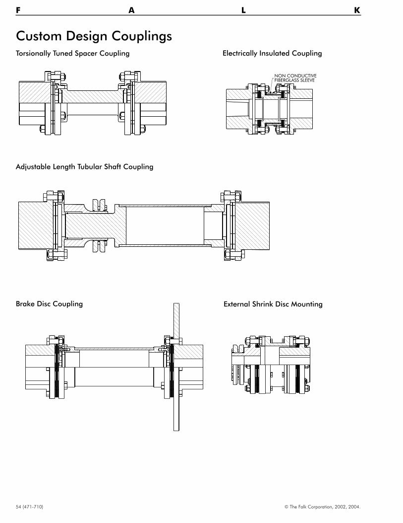
54 (471-710) © The Falk Corporation, 2002, 2004.
F A L K
Custom Design Couplings
Brake Disc Coupling
Electrically Insulated Coupling
aaabbb
aaabbb
NON CONDUCTIVEFIBERGLASS SLEEVE
External Shrink Disc Mounting
Torsionally Tuned Spacer Coupling
Adjustable Length Tubular Shaft Coupling

THE FALK CORPORATION
Plant Locations
Global Sales Offices
United States
Main
P.O. Box 492 Zip 53201-04923001 W. Canal StreetZip 53208-4200
Milwaukee, WI USAPhone: 1-800-852-FALK (3255) or414-342-3131FAX: 414-937-4359E-mail: [email protected]: www.falkcorp.com
Falk Capitol Drive12001 West Capitol DriveMilwaukee, WI 53222-1003414-438-3031FAX: 414-438-3049
Falk Auburn1600 Pumphrey Ave.Auburn, AL 36832334-321-9120FAX: 334-821-9103
Falk Renew1903 South Moorland BlvdNew Berlin, WI 53151262-317-1420FAX: 262-317-1428
Falk Australia Pty.34-36 Broadmeadow RdBroadmeadow, NSW 229461-2-4962-8000FAX: 61-2-4962-8001
Atlanta, GA334-728-0747
Baltimore, MD717-993-5144
Birmingham, AL205-661-3933
Charleston, WV304-595-1394
Charlotte, NC704-531-9250
Chicago, IL847-677-6492
Cincinnati, OH513-563-9699
Cleveland, OH330-528-1557
Dallas, TX469-556-7313
Denver, CO303-980-5131
Detroit, MI248-969-2553
Houston, TX469-556-7313
Kansas City, KS913-685-3254
Memphis, TN901-309-0340
Miami, FL954-436-6055
Milwaukee, WI262-646-4346
Minneapolis, MN763-522-0994
New Orleans, LA504-832-1448
Northeast860-355-0478
Northwest360-546-3411
Omaha, NE402-896-4520
Phoenix, AZ480-460-7188
Pittsburgh, PA412-563-1754
Richmond, VA804-747-8241
Rochester, NY585-223-5205
St. Louis, MO636-256-7600
Salt Lake City, UT801-268-4419
Tampa, FL941-358-1045
Victorville, CA760-401-0749
Vancouver, WA360-944-6780
Calgary, AB403-225-6630
Montreal, PQ450-424-7100
Toronto, ON416-674-0346
Vancouver, BC604-946-8506
Mexico, D.F.52-5-333-2500
Santiago, Chile56-2-231-5647
Sao Paulo, Brazil55-11-882-1000
Canada
Latin America
Europe
Asia/Pacific
Distribution Centers
Brighouse, United Kingdom44-1484-401872
Korea82-42-603-5644
Newcastle, Australia61-2-4962-8000
Perth, Australia61-8-9414-7800
Shanghai, China86-21-6219-6847
Singapore65-444-0388
Taiwan886-7-556-0263
Auburn, ALPH 334-821-9100FAX 414-937-4003
Doncaster, United KingdomPH 44-1484-401872FAX 44-1484-401341
Milwaukee, WIPH 414-342-3131FAX 414-937-4359
Sacramento, CAPH 877-937-6744FAX 414-937-4444
Toronto, ONPH 416-675-6071FAX 416-213-1020
South Africa
Gauteng, SA27-11-422-2496