Embed Size (px)
Citation preview
GEOTHERMAL TRAINING PROGRAMME Reports 2012 Orkustofnun, Grensasvegur 9, Number 20 IS-108 Reykjavik, Iceland
419
ACID STIMULATION OF GEOTHERMAL WELLS IN MEXICO, EL SALVADOR AND THE PHILIPPINES
Lilibeth Morales Alcalá Comisión Federal de Electricidad, GPG Alejandro Volta 655, Col. Electricistas
Morelia, Michoacán MEXICO
ABSTRACT
Acid treatments are among the most common treatments used for increasing formation permeability in undamaged wells, as well as in removing formation damage. This is due to the acid’s ability to dissolve depositions of minerals that cause decreased mass flow rate or low injection capacity. One of the acid treatments is called matrix acidizing, which is a technique that involves the injection of acid into the formation through the well at a pressure below the pressure at which a fracture can be opened. In several countries such as Mexico, El Salvador and the Philippines, this stimulation technique has been used for several years, in both production and injection wells with successful results. Although the matrix acidizing technique applied in each country is based on the same treatment, there are differences between them. The main differences consist of the injected acid concentration and the volume used in each stage. Other variations include the omission of post-flush in the Philippines and also in some cases in El Salvador, and the use of fresh water for the over-flush in El Salvador and the Philippines while geothermal water is used in Mexico. Some wells in El Salvador and also in the Philippines have been treated with sandstone acid (RPHF) instead of hydrochloric acid (HCl), as is used in regular mud acid for the main flush, and that is probably the most important difference between the treatment design in Mexico and that in the other two countries.
1. INTRODUCTION The key issue in geothermal development, with respect to generating electricity, is the ability to reach formations with sufficient flow (steam or brine) and storage capacity that can provide fluids with sufficient energy to drive a surface turbine to generate electricity for a long enough period of time to make the project economically viable. Unfortunately, during long-term production the mass or production rates decline. These changes in the geothermal wells can be caused by several reasons, e.g. effects of a lack of connectivity to main fluid conduits or formation damage due to sedimentation in the casing and/or in the feedzones surrounding the well (Flores and Morales, 2012).
Morales Alcalá 420 Report 20
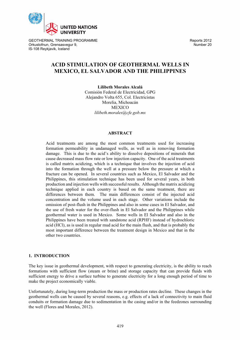
Stimulation techniques have the potential to increase formation permeability and remove the damage in the formation which causes low flow-rate in the well. Low productivity, due to lack of communication with the naturally occurring main conduits for fluid flow, can be improved by cleaning and by thermal and/or hydraulic fracturing of the wells, usually applied at the end of drilling. Sometimes it is necessary to treat damages due to mud invasion into open fractures, blocked pores or minor flow channels present in the host rock, or sedimentation problems. These problems can be reduced with an acid job at the end of drilling, or later during the well‘s production lifespan (Flores et al., 2005). Acids have been used due to their ability to dissolve minerals and drilling mud. The treatments which use acid, called acid treatments, are of two kinds: matrix acidizing and acid fracturing. In many countries these techniques have been applied, mainly matrix acidizing, in order to maintain or increase the flow rate. This treatment consists mainly of injecting a mixture of acid into the formation around the well, with the aim of dissolving calcite or silica scaling, or drilling mud that causes a decrease in the production or injection capacity of the well. In Mexico, several acidizing jobs have been carried out since the year 2000, with excellent results, both in production wells and injection wells. El Salvador and the Philippines are two other countries where matrix acidizing has been applied with similar success. The main design of the treatment is similar, but there are notable differences which will be analysed later in this paper along with the main results. The following study starts with a general description of acid treatments, followed by an overview of acid treatments in Mexico, including a case study. Then overviews are presented on acid stimulation in El Salvador and the Philippines, followed by a comparison of the acid treatments in the three countries. Finally, conclusions are presented. 2. ACID TREATMENTS Acids have the ability to dissolve formation minerals and foreign material, such as drilling mud, which may be introduced into the formation during well drilling or work over procedures, as well as precipitated minerals during production. This is the reason for utilizing acids to stimulate geothermal wells, to increase flow production or injection capacity (Williams et al., 1979). The different techniques fall into one of two categories: matrix acidizing and acid fracturing.
Matrix acidizing consists of injecting acid into the formation of the well at a pressure below the pressure at which a fracture can be opened. This technique is presented in more detail in Chapter 2.1. In acid fracturing, the acid injected into the formation must have high enough pressure to fracture the formation or open existing fractures. Two of the most important characteristics for each technique are show in Figure 1 (André et al., 2006). Due to its success in eliminating the damage in wells, matrix acidizing has become one of the most used stimulation techniques in treatments of geothermal wells around the world, for example in Mexico, El Salvador and the Philippines.
FIGURE 1: Acid treatment techniques: matrix acidizing and fracture acidizing
(modified from André et al., 2006)
Report 20 421 Morales Alcalá
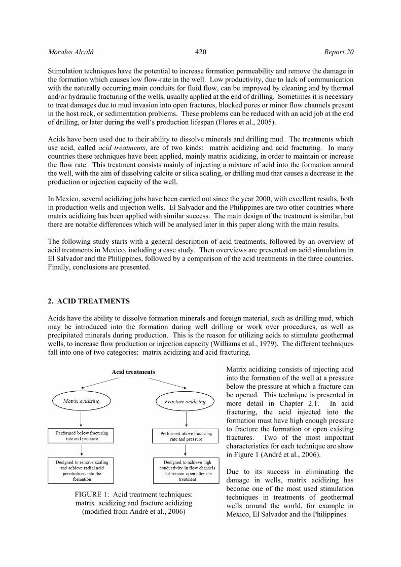
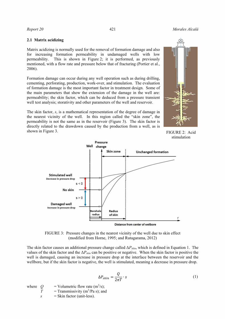
2.1 Matrix acidizing Matrix acidizing is normally used for the removal of formation damage and also for increasing formation permeability in undamaged wells with low permeability. This is shown in Figure 2; it is performed, as previously mentioned, with a flow rate and pressure below that of fracturing (Portier et al., 2006). Formation damage can occur during any well operation such as during drilling, cementing, perforating, production, work-over, and stimulation. The evaluation of formation damage is the most important factor in treatment design. Some of the main parameters that show the extension of the damage in the well are: permeability; the skin factor, which can be deduced from a pressure transient well test analysis; storativity and other parameters of the well and reservoir. The skin factor, s, is a mathematical representation of the degree of damage in the nearest vicinity of the well. In this region called the “skin zone”, the permeability is not the same as in the reservoir (Figure 3). The skin factor is directly related to the drawdown caused by the production from a well, as is shown in Figure 3.
FIGURE 3: Pressure changes in the nearest vicinity of the well due to skin effect (modified from Horne, 1995; and Rutagarama, 2012)
The skin factor causes an additional pressure change called ΔPskin, which is defined in Equation 1. The values of the skin factor and the ΔPskin can be positive or negative. When the skin factor is positive the well is damaged, causing an increase in pressure drop at the interface between the reservoir and the wellbore, but if the skin factor is negative, the well is stimulated, meaning a decrease in pressure drop.
∆2
∙ (1)
where Q = Volumetric flow rate (m3/s); T = Transmissivity (m3/Pa s); and s = Skin factor (unit-less).
FIGURE 2: Acid stimulation
Morales Alcalá 422 Report 20
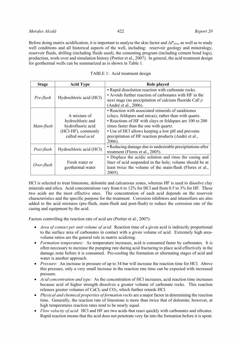
Before doing matrix acidification, it is important to analyse the skin factor and ΔPskin, as well as to study well conditions and all historical aspects of the well, including: reservoir geology and mineralogy, reservoir fluids, drilling (including fluids used), the cementing program (including cement bond logs), production, work-over and simulation history (Portier et al., 2007). In general, the acid treatment design for geothermal wells can be summarized as is shown in Table 1.
TABLE 1: Acid treatment design
Stage Acid Type Role played
Pre-flush Hydrochloric acid (HCl)
▪ Rapid dissolution reaction with carbonate rocks. ▪ Avoids further reaction of carbonates with HF in the next stage (no precipitation of calcium fluoride CaF2) (André et al., 2006).
Main-flush
A mixture of hydrochloric and hydrofluoric acid
(HCl-HF), commonly called mud acid
▪ Reaction with associated minerals of sandstones (clays, feldspars and micas), rather than with quartz. ▪ Reactions of HF with clays or feldspars are 100 to 200 times faster than the one with quartz. ▪ Use of HCl allows keeping a low pH and prevents precipitation of HF reaction products (André et al., 2006).
Post-flush Hydrochloric acid (HCl) ▪ Reducing damage due to undesirable precipitations after treatment (Flores et al., 2005).
Over-flush Fresh water or
geothermal water
▪ Displace the acidic solution and rinse the casing and liner of acid suspended in the hole; volume should be at least twice the volume of the main-flush (Flores et al., 2005).
HCl is selected to treat limestone, dolomite and calcareous zones, whereas HF is used to dissolve clay minerals and silica. Acid concentrations vary from 6 to 12% for HCl and from 0.5 to 3% for HF. These two acids are the most effective ones. The concentration of each acid depends on the reservoir characteristics and the specific purpose for the treatment. Corrosion inhibitors and intensifiers are also added to the acid mixtures (pre-flush, main-flush and post-flush) to reduce the corrosion rate of the casing and equipment by the acid. Factors controlling the reaction rate of acid are (Portier et al., 2007):
Area of contact per unit volume of acid: Reaction time of a given acid is indirectly proportional to the surface area of carbonates in contact with a given volume of acid. Extremely high area-volume ratios are the general rule in matrix acidizing.
Formation temperature: As temperature increases, acid is consumed faster by carbonates. It is often necessary to increase the pumping rate during acid fracturing to place acid effectively in the damage zone before it is consumed. Pre-cooling the formation or alternating stages of acid and water is another approach.
Pressure: An increase in pressure of up to 34 bar will increase the reaction time for HCl. Above this pressure, only a very small increase in the reaction rate time can be expected with increased pressure.
Acid concentration and type: As the concentration of HCl increases, acid reaction time increases because acid of higher strength dissolves a greater volume of carbonate rocks. This reaction releases greater volumes of CaCl2 and CO2, which further retards HCl.
Physical and chemical properties of formation rocks are a major factor in determining the reaction time. Generally, the reaction rate of limestone is more than twice that of dolomite; however, at high temperatures reaction rates tend to be nearly equal.
Flow velocity of acid: HCl and HF are two acids that react quickly with carbonates and silicates. Rapid reaction means that the acid does not penetrate very far into the formation before it is spent.
Report 20 423 Morales Alcalá
In fracture acidizing, an increase in the pumping rate increases fracture width. This decreases the area-volume ratio, thereby increasing acid reaction time.
Geothermal wells that are candidates for acidizing are, for example: those which have been damaged by drilling mud, those in which drill cuttings have been lost into the formation fractures, or those with scaling (calcium carbonate, silica, calcium sulphate, and mixtures). In order to make the most of acidizing, the acid treatment process must be carefully planned. The general approach is as follows (Portier et al., 2007):
a) Select an appropriate well for stimulation; b) Design an effective treatment; and c) Monitor the treatment for subsequent improvement.
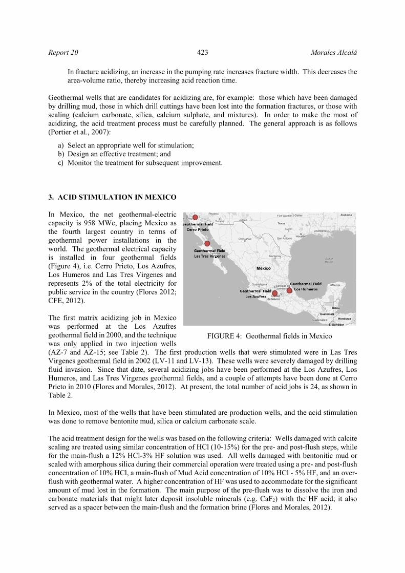
3. ACID STIMULATION IN MEXICO In Mexico, the net geothermal-electric capacity is 958 MWe, placing Mexico as the fourth largest country in terms of geothermal power installations in the world. The geothermal electrical capacity is installed in four geothermal fields (Figure 4), i.e. Cerro Prieto, Los Azufres, Los Humeros and Las Tres Virgenes and represents 2% of the total electricity for public service in the country (Flores 2012; CFE, 2012). The first matrix acidizing job in Mexico was performed at the Los Azufres geothermal field in 2000, and the technique was only applied in two injection wells (AZ-7 and AZ-15; see Table 2). The first production wells that were stimulated were in Las Tres Virgenes geothermal field in 2002 (LV-11 and LV-13). These wells were severely damaged by drilling fluid invasion. Since that date, several acidizing jobs have been performed at the Los Azufres, Los Humeros, and Las Tres Virgenes geothermal fields, and a couple of attempts have been done at Cerro Prieto in 2010 (Flores and Morales, 2012). At present, the total number of acid jobs is 24, as shown in Table 2. In Mexico, most of the wells that have been stimulated are production wells, and the acid stimulation was done to remove bentonite mud, silica or calcium carbonate scale. The acid treatment design for the wells was based on the following criteria: Wells damaged with calcite scaling are treated using similar concentration of HCl (10-15%) for the pre- and post-flush steps, while for the main-flush a 12% HCl-3% HF solution was used. All wells damaged with bentonitic mud or scaled with amorphous silica during their commercial operation were treated using a pre- and post-flush concentration of 10% HCl, a main-flush of Mud Acid concentration of 10% HCl - 5% HF, and an over-flush with geothermal water. A higher concentration of HF was used to accommodate for the significant amount of mud lost in the formation. The main purpose of the pre-flush was to dissolve the iron and carbonate materials that might later deposit insoluble minerals (e.g. CaF2) with the HF acid; it also served as a spacer between the main-flush and the formation brine (Flores and Morales, 2012).
FIGURE 4: Geothermal fields in Mexico

Morales Alcalá 424 Report 20
TABLE 2: Acid stimulations in geothermal wells in México
Los
Azu
fres
Well name
Year Type of
well Placement technique
Type of damage
AZ-7 2000 Injection Drill pipe Silica scaling AZ-15 2000 Injection Drill pipe Silica scaling AZ-64 2005 Production Drill pipe Mud damage AZ-9AD 2005 Production Drill pipe Mud damage AZ-8 2005 Injection Drill pipe Silica scaling AZ-9A 2006 Production Drill pipe Mud damage AZ-56R 2006 Production Drill pipe Mud damage AZ-52 2008 Injection Coiled tubing Silica scaling AZ-25 2008 Production Coiled tubing Silica scaling AZ-68D 2008 Production Coiled tubing Mud damage AZ-57 2010 Production Coiled tubing Silica scaling AZ-36 2010 Production Coiled tubing Silica scaling AZ-51 2010 Production Coiled tubing Silica scaling
Las
Tre
s V
irge
nes
LV-13 2002 Production Coiled tubing Mud damage LV-11 2002 Production Coiled tubing Mud damage LV-4 2004 Production Coiled tubing Calcite scaling LV-13 2004 Production Coiled tubing Calcite scaling LV-3 2006 Production Coiled tubing Calcite scaling LV-4A 2007 Production Coiled tubing Mud damage LV-13D 2007 Production Coiled tubing Mud damage LV-6 2010 Production Coiled tubing Mud damage
Los
H
um
eros
H-1D 2010 Production Drill pipe Silica and calcite
scaling
H-33 2012 Production Bull Heading Silica and calcite
scaling H-41 2012 Production Bull Heading Low permeability
Cer
ro
Pri
eto 307 2010 Production Coiled tubing Mud damage
208 2010 Production Coiled tubing Mud damage
After the matrix stimulations, significant increases in production were measured. The results were encouraging, showing production increases of up to 540%. Some of the results from the acidizing jobs in Los Azufres geothermal field, where most of the wells treated in Mexico are located, are shown in Tables 3 and 4. As observed in Table 3, greater improvement in production wells was obtained in wells damaged due to mud drilling, irrespective of the placement technique (drill pipe or coiled tubing). In injection wells (Table 4), wells AZ-8 and AZ-52 showed an improvement of more than 100% in injection capacity. At the beginning of 2012, an economic analysis was done in order to estimate the cost-benefits of acidizing with different placement techniques (Table 5). A comparison between using a drill pipe or coiled tubing showed that the average improvement in steam production, obtained after matrix acidizing, was greater with a drill pipe than with coiled tubing, as shown in Table 5, but also that the cost of the operation was more expensive for a drill pipe than for coiled tubing. Only two acidizing jobs using bull heading were done, and both of them were much less expensive, since it did not require major equipment. But further investigation needs to be done to evaluate cost versus results in terms of production improvement (Flores and Morales, 2012).

Report 20 425 Morales Alcalá
TABLE 3: Results of acid jobs in production wells in México
Production well
Drilling date
Acidizing date
Steam flowrate (t/h) Improvement (%)
Post acidizing compared to: Type of
damage Post
drillingPre
acidizingPost
acidizingPost
drilling Pre
acidizing AZ-9AD 2003 2005 22 22 68 209% 209% Mud damageAZ-9A 2001 2006 15 25 67 347% 168% Mud damageAZ-56R 2002 2006 15 15 70 367% 367% Mud damageAZ-25 1985 2008 40 16 30 ----- 88% Silica scalingAZ-68D 2006 2008 10 10 64 540% 540% Mud damageAZ-57 1989 2010 25 15 20 ----- 33% Silica scalingAZ-36 1982 2010 44 15 35 ----- 133% Silica scalingAZ-51 1986 2010 37 17 42 13% 147% Silica scaling
TABLE 4: Results of acid jobs in injection wells in México
Injection well
Drilling date
Acidizing date
Injection capacity (t/h) Improvement (%)
Post acidizing compared to: Type of
damage Post
drillingPre
acidizingPost
acidizingPost
drilling Pre
acidizing AZ-7 1992 2000 600 750 850 42% 13% Silica scaling AZ-15 1980 2000 350 340 450 29% 32% Silica scaling AZ-8 1988 2005 290 180 410 41% 128% Silica scaling AZ-52 1987 2008 350 70 170 ------ 143% Silica scaling
TABLE 5: Cost and average improvement for different placement techniques
(Flores and Morales, 2012)
Placement technique
Average price 2011 (USD)
Average improvement
Drilling pipe 1 195 339 249% Coiled Tubing 866 181 158% Bull heading 81 660 25%
3.1 A case study of acid treatment of well H-1D, Los Humeros geothermal field Candidate wells chosen for stimulation show either some damage at the end of the drilling (for new wells) or a decrease in the flow production, pressure or decreased capacity of injection, in the case of long-time production or injection. The history of production or injection and injection tests give the first indications of damage inside the well or in the nearest vicinity of the well. In 2012, 3 wells in the geothermal field Los Humeros were selected for stimulation, H-1D, H-33 and H-41. The stimulation process for well H-1D is described below. Well H-1D was the first production well in Los Humeros geothermal field, drilled in October 1985, to a depth of 1458 m (Figure 5a) and in 1995 was drilled as a directional well to 1850 m depth. H-1D is a high temperature well, and it was chosen for acidizing due to the decrease in the production rate. The feed zones are located in the interval of 1250-1850 m depth (Figure 5b).
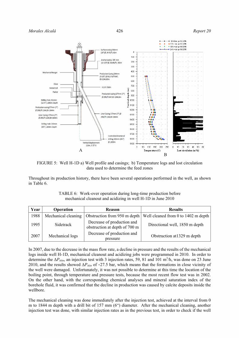
Morales Alcalá 426 Report 20
A B
FIGURE 5: Well H-1D a) Well profile and casings; b) Temperature logs and lost circulation data used to determine the feed zones
Throughout its production history, there have been several operations performed in the well, as shown in Table 6.
TABLE 6: Work-over operation during long-time production before mechanical cleanout and acidizing in well H-1D in June 2010
Year Operation Reason Results
1988 Mechanical cleaning Obstruction from 950 m depth Well cleaned from 0 to 1402 m depth
1995 Sidetrack Decrease of production and
obstruction at depth of 700 m Directional well, 1850 m depth
2007 Mechanical logs Decrease of production and
pressure Obstruction at1329 m depth
In 2007, due to the decrease in the mass flow rate, a decline in pressure and the results of the mechanical logs inside well H-1D, mechanical cleanout and acidizing jobs were programmed in 2010. In order to determine the ∆Pskin, an injection test with 3 injection rates, 59, 81 and 101 m3/h, was done on 23 June 2010, and the results showed ∆Pskin of +27.5 bar, which means that the formations in close vicinity of the well were damaged. Unfortunately, it was not possible to determine at this time the location of the boiling point, through temperature and pressure tests, because the most recent flow test was in 2002. On the other hand, with the corresponding chemical analyses and mineral saturation index of the borehole fluid, it was confirmed that the decline in production was caused by calcite deposits inside the wellbore. The mechanical cleaning was done immediately after the injection test, achieved at the interval from 0 m to 1844 m depth with a drill bit of 157 mm (6“) diameter. After the mechanical cleaning, another injection test was done, with similar injection rates as in the previous test, in order to check if the well
Report 20 427 Morales Alcalá
had improved. The results showed that the damage was eliminated; the obtained result was ∆Pskin of -4.8 bar. In order to eliminate the calcite scaling, the acid concentration in the main-flush was HCl 12% - HF 3% (Mud Acid), and 10% HCl for the pre- and post-flush, and finally geothermal water as the over-flush. The injection in each step of the acid stimulation was done through a drilling pipe. The drilling pipe was stopped at each one of the intervals to be treated. The intervals were 1250-1300, 1350-1400, 1550-1600 and 1700-1750 m, corresponding to the feed zones. The operation parameters are shown in Table 7.
TABLE 7: Operation parameters for each step and interval to be treated during acid stimulations on 13 July 2010
Depth (m)
Injected flow Volume injected
(m3)
Flow rate (m3/h)
Pressure (bar-a)
1250-1300
10% HCl Pre-flush 31 131 139 12% HCl-3% HF 47 135 141 10% HCl Post-flush 6.5 134 111 Divergent 13% HCl (in gel phase) 16 135 93 Over-flush 94 138 103
1350-1400
10% HCl Pre-flush 31 128 114 12% HCl-3% HF 47 135 115 10% HCl Post-flush 6.5 135 113 Over-flush 94 137 110
1550-1600
10% HCl Pre-flush 31 132 117 12% HCl-3% HF 47 136 120 10% HCl Post-flush 6.5 137 117 Over-flush 94 138 110
1700-1750
10% HCl Pre-flush 31 129 114 12% HCl-3% HF 47 137 115 10% HCl Post-flush 6.5 136 113 Over-flush 94 136 117
After the acid stimulation, it was impossible to do an injection test, although it had been planned, due to steam requirements for the generation units, but the improvement in the mass flow rate was very clear. On 15 July, two days after the stimulation, the steam flow rate was 18 t/h and the brine flow rate was 56 t/h, with 8.7 bar-a wellhead pressure (8 bar-a separation pressure). In September, 10 weeks after the stimulation, the steam production of the well increased to 46 t/h steam flow, and the wellhead pressure was 21 bar-a. With this improvement, the well was able to generate 3.3 MWe. These values represent an increase of about 7% with respect to the original steam flow rate (42 t/h) from the well, and more than a 600% increase, with respect to the production rate before stimulation (6 t/h). It was therefore concluded that the mechanical cleaning and acid stimulation were successful. Figure 6 shows the evolution of the long-term production rates as well as the wellhead pressure, orifice and the enthalpy. The vertical line in 2010 in Figure 6 shows the time of the mechanical cleanout and acid stimulation, where the improvements are outstanding, especially the increase in the mass production rate (Figure 6b).

Morales Alcalá 428 Report 20
FIGURE 6: Well H-1D from 2003 to 2011; a) Well head pressure (bar-a), orifice (inches), b) Mass flow rate (t/h) and steam flow rate (t/h), c) Enthalpy (kJ/kg), steam fraction
4. ACID STIMULATION IN EL SALVADOR Geothermal energy production in El Salvador dates back to 1975, with the first 30 MWe unit in Ahuachapán. Geothermal energy has gradually become one of the main sources of electricity in the country, where two geothermal fields are in operation (Figure 7): Ahuachapán and Berlín with an installed capacity of 95 MWe and 109 MWe, respectively, placing El Salvador as the tenth largest country in terms of geothermal installations in the world. Two more geothermal projects are being developed in the areas of San Vicente and Chinameca. At present, almost 26% of the utilization of electricity in El Salvador is from geothermal resources (Guidos and Burgos, 2012). Stimulation techniques have been applied in both of the geothermal fields in El Salvador, to production wells with damage due to mud or drill cuttings or calcite scaling or silica scaling, and to treat mud damage in injection wells. The number of stimulation treatments is around 50, in 20 production and 22 injection wells, as is shown in Tables 8 and 9. Some of them were treated with mechanical intervention as well as chemical stimulation and others only with chemical stimulation. The production wells which have been stimulated were usually mechanically cleaned before the acid stimulation. The mechanical cleaning is sometimes done using a drill rig or coil tubing unit. The use of different placement
Wel
lhea
dpr
essu
re(b
ara)
Orif
ice
(inch
es)
Ent
halp
y(k
J/kg
)
Ste
amfr
actio
n
Flo
wra
te(t
/h)
FIGURE 7: Geothermal fields in El Salvador
Report 20 429 Morales Alcalá
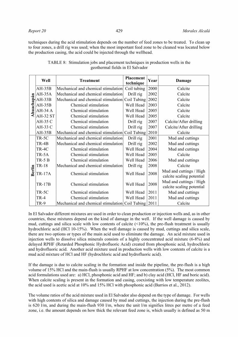
techniques during the acid stimulation depends on the number of feed zones to be treated. To clean up to four zones, a drill rig was used; when the most important feed zone to be cleaned was located below the production casing, the acid could be injected through the wellhead.
TABLE 8: Stimulation jobs and placement techniques in production wells in the geothermal fields in El Salvador
Ah
uac
hap
án
Well Treatment Placement technique
Year Damage
AH-35B Mechanical and chemical stimulation Coil tubing 2000 Calcite AH-35A Mechanical and chemical stimulation Drill rig 2002 Calcite AH-33B Mechanical and chemical stimulation Coil Tubing 2002 Calcite AH-35B Chemical stimulation Well Head 2003 Calcite AH-34 A Chemical stimulation Well Head 2005 Calcite AH-32 ST Chemical stimulation Well Head 2005 Calcite AH-35 C Chemical stimulation Drill rig 2007 Calcite/After drilling AH-33 C Chemical stimulation Drill rig 2007 Calcite/After drilling AH-35B Mechanical and chemical stimulation Coil Tubing 2010 Calcite
Ber
lín
TR-5C Mechanical and chemical stimulation Drill rig 2001 Mud and cuttings TR-4B Mechanical and chemical stimulation Drill rig 2002 Mud and cuttings TR-4C Chemical stimulation Well Head 2004 Mud and cuttings TR-5A Chemical stimulation Well Head 2005 Calcite TR-5 B Chemical stimulation Well Head 2006 Mud and cuttings TR-18 Mechanical and chemical stimulation Drill rig 2008 Calcite
TR-17A Chemical stimulation Well Head 2008Mud and cuttings / High calcite scaling potential
TR-17B Chemical stimulation Well Head 2008Mud and cuttings / High calcite scaling potential
TR-5C Chemical stimulation Well Head 2011 Mud and cuttings TR-4 Chemical stimulation Well Head 2011 Mud and cuttings TR-9 Mechanical and chemical stimulation Coil Tubing 2011 Calcite
In El Salvador different mixtures are used in order to clean production or injection wells and, as in other countries, these mixtures depend on the kind of damage in the well. If the well damage is caused by mud, cuttings and silica scale with low contents of calcite (<10%), the pre-flush treatment is usually hydrochloric acid (HCl 10-15%). When the well damage is caused by mud, cuttings and silica scale, there are two options or types of the main acid used to eliminate the damage. An acid mixture used in injection wells to dissolve silica minerals consists of a highly concentrated acid mixture (6-8%) and delayed RPHF (Retarded Phosphonic Hydrofluoric Acid) created from phosphonic acid, hydrochloric and hydrofluoric acid. Another acid mixture used in production wells with low contents of calcite is a mud acid mixture of HCl and HF (hydrochloric acid and hydrofluoric acid). If the damage is due to calcite scaling in the formation and inside the pipeline, the pre-flush is a high volume of 15% HCl and the main-flush is usually RPHF at low concentration (5%). The most common acid formulations used are: a) HCl, phosphonic acid and HF; and b) clay acid (HCl, HF and boric acid). When calcite scaling is present in the formation and casing, coexisting with low temperature zeolites, the acid used is acetic acid at 10% and 15% HCl with phosphonic acid (Barrios et al., 2012). The volume ratios of the acid mixture used in El Salvador also depend on the type of damage. For wells with high contents of silica and damage caused by mud and cuttings, the injection during the pre-flush is 620 l/m, and during the main-flush 930 l/m, where the unit l/m signifies litres per metre of a feed zone, i.e. the amount depends on how thick the relevant feed zone is, which usually is defined as 50 m
Morales Alcalá 430 Report 20
for the acidizing work. On the other hand, for wells with a potential for calcite and mud damage, the pre-flush injection is 1240-1490 l/m and for the main-flush it is 930 l/m.
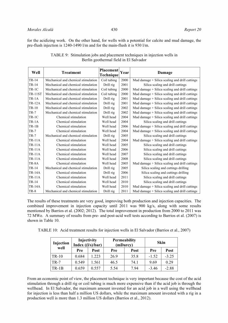
TABLE 9: Stimulation jobs and placement techniques in injection wells in
Berlín geothermal field in El Salvador
Well Treatment PlacementTechnique
Year Damage
TR-14 Mechanical and chemical stimulation Coil tubing 2000 Mud damage + Silica scaling and drill cuttings TR-14 Mechanical and chemical stimulation Drill rig 2001 Silica scaling and drill cuttings TR-1C Mechanical and chemical stimulation Coil tubing 2000 Mud damage + Silica scaling and drill cuttings TR-11ST Mechanical and chemical stimulation Coil tubing 2000 Mud damage + Silica scaling and drill cuttings TR-1A Mechanical and chemical stimulation Drill rig 2001 Mud damage + Silica scaling and drill cuttings TR-12A Mechanical and chemical stimulation Drill rig 2001 Mud damage + Silica scaling and drill cuttings TR-10 Mechanical and chemical stimulation Drill rig 2002 Mud damage + Silica scaling and drill cuttings TR-7 Mechanical and chemical stimulation Drill rig 2002 Mud damage + Silica scaling and drill cuttings TR-1C Chemical stimulation Well head 2004 Mud damage + Silica scaling and drill cuttings TR-1A Chemical stimulation Well head 2004 Silica scaling and drill cuttings TR-1B Chemical stimulation Well head 2006 Mud damage + Silica scaling and drill cuttings TR-7 Chemical stimulation Well head 2004 Mud damage + Silica scaling and drill cuttings TR-7 Mechanical and chemical stimulation Drill rig 2005 Silica scaling and drill cuttings TR-11A Chemical stimulation Well head 2004 Mud damage + Silica scaling and drill cuttings TR-11A Chemical stimulation Well head 2005 Silica scaling and drill cuttings TR-11A Chemical stimulation Well head 2006 Silica scaling and drill cuttings TR-11A Chemical stimulation Well head 2007 Silica scaling and drill cuttings TR-11A Chemical stimulation Well head 2008 Silica scaling and drill cuttings TR-8A Chemical stimulation Well head 2005 Mud damage + Silica scaling and drill cuttings TR-14 Mechanical and chemical stimulation Drill rig 2005 Silica scaling and cuttings drilling TR-14A Chemical stimulation Drill rig 2006 Silica scaling and cuttings drilling TR-11A Chemical stimulation Well head 2011 Silica scaling and drill cuttings TR-14 Chemical stimulation Well head 2010 Silica scaling and drill cuttings TR-14A Chemical stimulation Well head 2010 Mud damage + Silica scaling and drill cuttings TR-8 Mechanical and chemical stimulation Drill rig 2011 Mud damage + Silica scaling and drill cuttings
The results of these treatments are very good, improving both production and injection capacities. The combined improvement in injection capacity until 2011 was 900 kg/s, along with some results mentioned by Barrios et al. (2002; 2012). The total improvement in production from 2000 to 2011 was 72 MWe. A summary of results from pre- and post-acid well tests according to Barrios et al. (2007) is shown in Table 10.
TABLE 10: Acid treatment results for injection wells in El Salvador (Barrios et al., 2007)
Injection well
Injectivity Index ((l/s)/bar)
Permeability (mDarcy)
Skin
Pre Post Pre Post Pre Post
TR-10 0.684 1.223 26.9 35.8 -1.52 -3.25
TR-7 0.549 1.561 46.5 74.1 9.69 0.29
TR-1B 0.659 0.557 5.54 7.94 -3.46 -2.88
From an economic point of view, the placement technique is very important because the cost of the acid stimulation through a drill rig or coil tubing is much more expensive than if the acid job is through the wellhead. In El Salvador, the maximum amount invested for an acid job in a well using the wellhead for injection is less than half a million US dollars, while the maximum amount invested with a rig in a production well is more than 1.3 million US dollars (Barrios et al., 2012).

Report 20 431 Morales Alcalá
5. ACID STIMULATION IN THE PHILIPPINES According to the Geothermal Energy Association (2012), the Philippines are the second-largest producer of geothermal electric energy in the world, and have at present 1,972 MWe installed in seven geothermal areas named Bac-Man, Leyte, Mindanao, Northern Negros, South Negros, Mak-Ban and Tiwi, as shown in Figure 8. Geothermal exploration started in 1962 and, at present, around 12% of the electricity consumption in the Philippines is from geothermal resources. As in other countries, mechanical cleanout and acid stimulation are done in the Philippines in order to keep or increase the production rate or the injection capacity. In some cases, mechanical drill-out of the mineral blockage within the wellbore is almost a pre-requisite to reduce the bulk of mineral blockage and reduce the cost of the acid treatment. But where mineral deposits were inside the production liner or nearby in the wellbore formation, enhanced permeability could not be achieved by mechanical cleaning. The production wells selected for work-over must fulfil at least one of these criteria:
The well’s output was reduced by at least 50%; The decline is not primarily attributed to reservoir
pressure drawdown; The obstruction is purely mineral deposition or a
damaged casing; and The integrity of the production casing warrants a drill string in order to be able to penetrate past
the obstruction.
To give an example, treatment for production wells with calcite scaling damage, located in South Negros geothermal area, was carried out in three stages: 1) pre-flush, that usually consisted of 10% hydrochloric acid (10% HCl) and inhibitors; 2) main-flush, where the mixture usually consisted of 12% hydrochloric acid and 5% hydrofluoric acid (12% HCl - 5% HF); and 3) over-flush, which was pure water. The injection at each step of the acid stimulation was usually done through a drilling pipe; the rate of the acid injection had to be as fast as possible in order to attain effective reaction with the scaling. The drilling pipe was run into the depths or intervals to be treated, starting from the topmost target zone, and going down one by one to the deepest zone (Amistoso et al., 2005). The treatment for injection wells with silica scaling damage, for example in Leyte geothermal area, is similar to the treatment for production wells, but some differences are to be found in the mixture injected during the main-flush. The acid used for injection wells consists of 10% hydrochloric acid (HCl) and 5% hydrofluoric acid (HF), and in the pre-flush and over-flush a similar solution is used as for production wells, i.e. 10% HCl and fresh water, respectively. A diverter is used for a dosing rate of more than 7 kilograms of benzoic acid per metre of feed zone (Malate et al., 1997). Some geothermal wells in the Philippines have been stimulated with sandstone acid, which is also used for treating sandstone formations in El Salvador. In the Bacman II Geothermal Field, a couple of production wells were treated with sandstone acid, a technique that is based on using a retarded HF acid mixture, and a phosphonic acid complex (HEDP) is used to hydrolyse the fluoride salt (NH4HF2) instead of the HCl which is used in regular mud acid (Di Lullo and Rae, 1996). The flow rate of the sandstone acid mixture of 10% HCl - 3% HF used for production wells OP-3D and OP-5DA was similar to that used for regular mud acid in a 930 l/m thick feed zone (Malate et al, 1998).
FIGURE 8: Geothermal fields in the Philippines

Morales Alcalá 432 Report 20
The results from the stimulations were successful for both production (Table 11) and injection wells (Table 12), as well as for both techniques, a traditional mud acid and sandstone acid. Sandstone acid was effective in treating sandstone formations in wells OP-3D and OP-5DA with production improvement of 104% and 173%, respectively according to Malate et al. (1998). They pointed out that reduction in downhole pressure caused a decline in the flow resistance and improved the wells’ acceptance, which was the case for these two wells. They improved significantly more than similar mud-damaged production wells previously treated with mud acid.
TABLE 11: Acid treatment results for production wells in the Philippines (Amistoso et al., 2005; and Malate et al., 1998)
Production well
Output (MW)
Pre acidizing
Post acidizing
Improvement%
PN31D 6 8.3 38 PN27D 5.1 4.5 ----- LG4D 3.9 6.7 72 PN13D 2.1 2.1 ----- OP-3D* 2.7 5.5 104 OP-5DA* 1.5 4.1 173
* Treated with sandstone acid
TABLE 12: Acid treatment results for injection wells in the Philippines (Malate et al., 1997)
Injection well
Injectivity Index ((l/s)/MPa)
Injection capacity (kg/s)
Skin
Pre acidizing
Post acidizing
Pre acidizing
Post acidizing
Pre acidizing
Post acidizing
MG7RD 15.2-15.6 108-120 81 370 6.2 -2.2 4R7D 6.8 17.7 36 91 3.2 1.8
4R12D 30.1 58.4 149 264 9.9 1
6. ANALYSIS AND COMPARISON A comparison between acidizing jobs that have been done in geothermal wells in the three countries discussed above, shows that similar acid mixtures are injected into the wells, in each step of the acidizing program, although the acid volumes are different for some of the stages. All this information is shown in Tables 13 and 14. In Mexico and the Philippines, in the treatment for production wells with calcite scaling damage (Table 13), the pre-flush consists of 10% of hydrochloric acid with a volume of 31 m3. In El Salvador the pre-flush can be of two types, 10-15% of hydrochloric acid or 5% RPHF (retarded phosphonic hydrofluoric acid), as was explained in Section 4, and the volume injected is different, i.e. from 62 m3 to 75 m3, which is higher than in the other countries. The volume for the mud acid or main-flush is similar for each one of the techniques applied in the three countries, which is a mixture of 10-12% HCl and 2-5% HF. The main difference is that in the Philippines and El Salvador the main-flush could be of two types: the previously mentioned mud acid and sandstone acid (RPHF); in geothermal wells in Mexico the mixture of 12% HCl-3% HF is the only mixture injected. The post-flush is only done in well treatments on a regular basis in Mexico and, generally, the acid used is similar to the acid used in the pre-flush (10% HCl). In some cases, the post-flush stage is also applied in El Salvador, but the fluid injected is either

Report 20 433 Morales Alcalá
only water mixed with the remaining HCl or, on certain occasions, 3% HCl. The last step in acidizing wells with calcite damage is the over-flush. In El Salvador and the Philippines, the fluid injected is fresh or pure water, whereas the injected fluid in Mexico consists of geothermal water. The volume is slightly different, as well, for each country. For example, 94 m3 (or two times the volume of the main-flush) of geothermal water is used in Mexico; almost the same volume (about 100 m3) is used in El Salvador; and finally for the Philippines, the volume must be at least equivalent to the drill string.
TABLE 13: Overview of the techniques applied for acid treatment in wells damaged due to calcite scaling in El Salvador, Mexico and the Philippines
Country Pre-flush Main-flush Post-flush Over-flush
Acid Vol. Acid Vol. Acid Vol. Acid Vol.
Mexico 10% HCl 31 m3 12% HCl - 3% HF 47 m3 10% HCl 6.5 m3 Geothermal water
94 m3
El Salvador a) 10-15% HCl b) Sandstone acid 5% (RPHF)
62-75 m3
a) 10% HCl - 5% HF (little calcite and damage by drilling mud and cuttings) b) Sandstone acid 5% (RPHF)
47 m3 3% HCl ---
Fresh water (condensed steam from
power plant)
About 100 m3
The Philippines
10% HCl 31 m3 a) 12% HCl - 5% HF b) Sandstone acid
47 m3 --- --- Pure water
At least equivalent to drill string
volume
TABLE 14: Overview of the techniques applied for acid treatment in El Salvador, Mexico
and the Philippines in wells damaged by silica scaling
The pre-flush, in the treatment for wells damaged due to silica scaling, is very similar in the three countries: the acid injected is 10-15% of hydrochloric acid, and the volume is the same, 31 m3. For the main-flush step, one difference is notable between El Salvador and the other countries, i.e. while mud acid is used in the main-flush in Mexico and the Philippines, the main-flush acid injection in El Salvador consists of 10% HCl - 5% HF or sandstone acid 7-8% (RPHF). In all three countries, the volume of acid injected in this step is similar, 47 m3. As for wells damaged with calcite scaling, a similarity between countries was found in the silica scaling treatment but also between the treatment of the calcite and silica scaling. In Mexico and sometimes in El Salvador the post-flush is applied in the treatment of silica scaling with 10% HCl acid injected (a similar concentration as in the pre-flush) with a volume of 6.5 m3 for Mexico, and a concentration of 3% HCl, with a variable volume of injection for El Salvador. In the over-flush for silica scaling or mud damage, both in El Salvador and the Philippines, the fluid injected is fresh or pure water, whereas the injected fluid in Mexico consists of geothermal water; the volume is slightly different as well for each country, as shown in Table 14. This is similar to the treatment for calcite scaling.
Country Pre-flush Main-flush Post-flush Over-flush
Acid Vol. Acid Vol. Acid Vol. Acid Vol. Mexico 10% HCl 31 m3 10% HCl - 5% HF 47 m3 10% HCl 6.5 m3 Geothermal water 94 m3
El Salvador 10-15%
HCl 31 m3
a) 10% HCl - 5% HFb) Sandstone acid 7- 8% (RPHF)
47 m3 3% HCl --- Fresh water
(condensed steam from power plant)
About 100 m3
The Philippines
10% HCl 31 m3 10% HCl-5%HF 47 m3 --- --- Pure water At least equivalent to drill string vol.
Morales Alcalá 434 Report 20
7. CONCLUSIONS Acid stimulations, due to their ability to dissolve formation minerals, depositions and foreign material, can potentially increase formation permeability, and remedy the damage in the geothermal well formation which causes low and decreased flow-rate in the well; this damage includes drilling mud which may be introduced into the formation during drilling or work-over procedures, and scales formed during production or injection. Matrix acidizing has become one of the most used stimulation techniques in the treatment of geothermal wells around the world, based on the excellent results achieved for both production and injection wells. Matrix acidizing consists of injecting a specific mixture of acid into a well, usually in three or four stages (pre-flush, main-flush, post-flush and over-flush). The most important factor in treatment design is the evaluation of formation damage. The decision of which acid to use, the acid concentration, and how much volume should be injected all depend on the type of damage. Mexico is one of the countries in which matrix acidizing has been applied in several wells with very good results. To give an example, in 2010 well H-1D was stimulated and the steam production increased about 7%, with respect to the original steam flow rate from the well, and more than a 600% increase with respect to the production rate just before stimulation. The results are also very good in El Salvador and the Philippines. The technique applied in each country is similar, but there are some differences in the concentrations of the injected acids and the volumes. For treatments of wells damaged due to calcite scaling, the pre-flush stages are very similar in Mexico and the Philippines. In El Salvador, the pre-flush can be done with two types of acids, and the injected volume is approximately twice that in the other countries. In the main-flush, the volume is similar in the three countries but the acid concentration differs a little in each country. Additionally, both in El Salvador and the Philippines, the main-flush can consist of sandstone acid or mud acid, whereas only mud acid is injected in Mexico. The post-flush and over-flush are also different. In Mexico, the post-flush is always performed, in El Salvador it is often omitted, and it is not performed at all in the Philippines. The over-flush is applied in all three countries, but in Mexico the over-flush consists of geothermal water, while in the other two countries, fresh water is injected. For wells damaged due to silica scaling or mud damage, the pre-flush in the treatment is similar in the three countries; both the acids injected and the volumes are the same. Regular mud acid is most often used in the main-flush in all three countries; the only difference is that in El Salvador sometimes sandstone acid is used as well. The similarities and differences of the post- and over-flush stages are similar to what applies for the treatment of calcite scaling. The cost of acid treatments varies between 0.5 and 1.3 M USD per treatment, as shown in an economic analysis for Mexico and El Salvador (Flores and Morales, 2012; Barrios et al., 2012). The placement technique directly affects the cost of the acid stimulation as it is more expensive when a drill rig or coiled tubing is used, than acidizing through the wellhead. On the other hand, in Mexico, the results are usually better when injecting the acid through the more expensive techniques, i.e. using the drill rig or the coiled tubing, probably because the injected acid is placed directly into the feed zones. As a result of this study, it is suggested that Mexico consider the operational parameters of the acidizing treatment in the two other countries. For example, removing the post-flush state and using fresh or pure water instead of geothermal water in the over-flush are advised in order to analyse whether these modifications would bring some production and economic benefits. The efficiency of the use of sandstone acid in the main-flush in geothermal wells in Mexico is something that should be studied carefully with regard to the type of rock formation of each geothermal field.

Report 20 435 Morales Alcalá
ACKNOWLEDGEMENTS I would like to express my sincere gratitude to the United Nations University Geothermal Training Programme and to specially thank the UNU staff: Dr. Ingvar Birgir Friðleifsson, Director; Mr. Lúdvík S. Georgsson, Deputy Director; Mr. Ingimar G. Haraldsson, Mr. Markús A.G. Wilde, Ms. Thórhildur Ísberg, and Ms. Málfrídur Ómarsdóttir. Thank you for all the help, assistance and care throughout the training. I am sincerely thankful to my supervisors: Dr. Svanbjörg Helga Haraldsdóttir, Mr. Sigvaldi Thordarson, Mr. Benedikt Steingrímsson, and Mr. Sverrir Þórhallsson, for their advice and patient dedication. Special thanks to my employer, Comisión Federal de Electricidad, to Ms. Magaly Flores Armenta for her support and encouragement to improve my knowledge and skills. Finally, I express my deepest gratitude to my family, friends and co-workers.
REFERENCES
Amistoso, A.E., Aqui, A.R., Yglopaz, D.M., and Malate, R.C.M, 2005: Sustaining steam supply in Palinpinon I production field, Southern Negros geothermal project, Philippines. Proceedings of the World Geothermal Congress 2005, Antalya, Turkey, 5 pp. André, L., Fritz, B., and Vuataz, F.D., 2006; Overview of chemical stimulations of EGS and non EGS reservoirs. Proceedings of the Engine Launching Conference, Orléans, France, 4-12. Barrios, L.A., Guerra, E., Jacobo P., and Mayorga, H., 2012: Acid stimulation of geothermal reservoirs. Paper presented at “Short Course on Geothermal Development and Geothermal Wells”, organized by UNU-GTP and LaGeo, Santa Tecla, El Salvador, 12 pp. Barrios, L.A., Quijano, J.E., Guerra, E., Mayorga, H., Rodriguez, A., Romero, R., 2007: Injection improvements in low permeability and negative skin wells, using mechanical cleanout and chemical stimulation, Berlin geothermal field, El Salvador. Geothermal Resources Council Transactions, 31, 141-146. Barrios, L.A., Quijano, J.E., Romero, R.E., Mayorga, H., Castro, M., and Caldera, J., 2002: Enhanced permeability by chemical stimulation at the Berlin geothermal field, El Salvador. Geothermal Resources Council, Transactions, 26, 73-78. CFE, 2012: CFE - statistics on generation (in Spanish). Comisión Federal de Electricidad, Mexico. Website: www.cfe.gob.mx/ConoceCFE/1_AcercadeCFE/Estadisticas/Paginas/Generacion.aspx Di Lullo, G., and Rae, P., 1996: A new acid for true stimulation of sandstone reservoirs. Proceedings of the 6th International Asia Pacific Oil & Gas Conference, Adelaide, Australia, 10 pp. Flores Armenta, M., 2012: Geothermal activity and development in Mexico - Keeping the production going. Paper presented at the “Short Course on Geothermal Development and Geothermal Wells”, Santa Tecla, El Salvador, 12 pp. Flores Armenta, M., Davies, D., Pálsson, B., 2005: Stimulation of geothermal wells, can we afford it? Proceedings of the World Geothermal Congress, Antalya, Turkey, 8 pp. Flores Armenta, M., and Morales, A.L., 2012: How much stimulation can we afford? Paper presented at the “Short Course on Geothermal Development and Geothermal Wells”, organized by UNU-GTP and LaGeo, Santa Tecla, El Salvador, 12 pp.
Morales Alcalá 436 Report 20
Geothermal Energy Association, 2012: Geothermal: international market overview report. Geothermal Energy Association, 26 pp. Website: www.geo-energy.org/pdf/reports/2012-GEA_International_Overview.pdf Guidos, J. and Burgos, J., 2012: Geothermal activity and development in El Salvador - producing and developing. Paper presented at the “Short Course on Geothermal Development and Geothermal Wells”, Santa Tecla, El Salvador, 12 pp. Horne, R.N., 1995: Modern well test analysis, a computer aided approach (2nd ed.). Petroway Inc., USA, 257 pp. Malate, R.C.M, Austria, J.J.C., Sarmiento, Z.F., Di Lullo, G., Sookprasong, P.A., and Francia, E.S., 1998: Matrix stimulation treatment of geothermal wells using sandstone acid. Proceedings of the 23rd Workshop on Geothermal Reservoir Engineering, Stanford University, Stanford, CA, 375-378. Malate, R.C.M, Yglopaz, D.M., Austria, J.J.C., Lacanilao, A.M. and Sarmiento, Z.F., 1997: Acid stimulation of injection wells in the Leyte geothermal power project, Philippines. Proceedings of the 22nd Workshop on Geothermal Reservoir Engineering, Stanford University, Stanford, CA, 267-272. Portier, S., André, L., and Vuataz, F.D., 2006: Modelling geochemical effects of acid treatments and comparison with field observations at Soultz-sous-Forêts geothermal site. Proceedings of the ENGINE – Enhanced Geothermal Innovative Network for Europe, Workshop 3, Stimulation of Reservoir and Microseismicity, Zürich, Switzerland, 13 pp. Portier, S., André, L., and Vuataz, F.D, 2007: Review on chemical stimulation techniques in oil industry and applications to geothermal systems. Proceedings of the ENGINE – Enhanced Geothermal Innovative Network for Europe, Workshop 4, Drilling, Stimulation and Reservoir Assessment, Zürich, Switzerland, 32 pp. Rutagarama, U., 2012: The role of well testing in geothermal resource assessment. University of Iceland, School of Engineering and Natural Sciences, Faculty of Earth Sciences, MSc. thesis, UNU-GTP report 2, 71 pp. Williams, B.B., Gidley, L.J., Schechter, S.R., 1979: Acidizing fundamentals. Society of Petroleum Engineers of AIME, NY, 1979, 123 pp.