Embed Size (px)
Citation preview
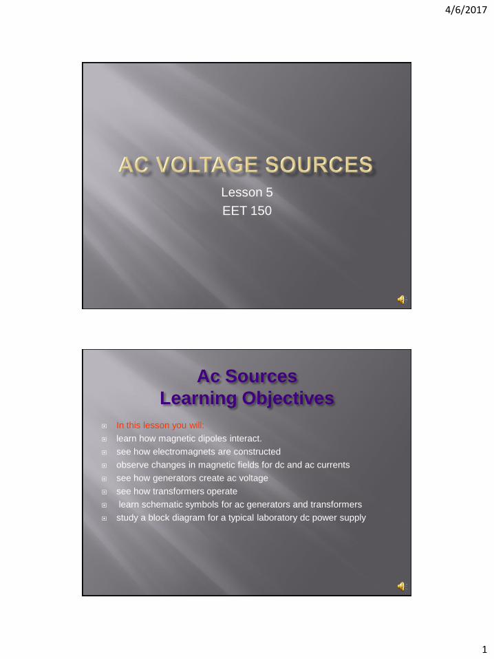
4/6/2017
1
Lesson 5
EET 150
Ac Sources
Learning Objectives
In this lesson you will:
learn how magnetic dipoles interact.
see how electromagnets are constructed
observe changes in magnetic fields for dc and ac currents
see how generators create ac voltage
see how transformers operate
learn schematic symbols for ac generators and transformers
study a block diagram for a typical laboratory dc power supply

4/6/2017
2
Magnetic fields exert force on objects
S N S N Opposite
Poles
Attract Force Force
S N S N Like Poles
Repel
Force Force
Magnetic
flux
Currents flowing in wires produce magnetic flux
Voltage
Source, V
Current
I
X1 I into
page
X1 X1 Y1 Y1
Y1 I into
page

4/6/2017
3
Coiling wire focuses flux
Dc current produces
constant flux
I
Magnetic
Field
Ac current produces alternating
flux
I
I
N
S
N
S
S
N
S N
A
B
C
D
Conductor
Loop
V
Time
Vo
lta
ge
, V
A
B
C
D
Rotating a conductor through a magnetic field produces an Ac voltage
generators (Alternators)
4/6/2017
4
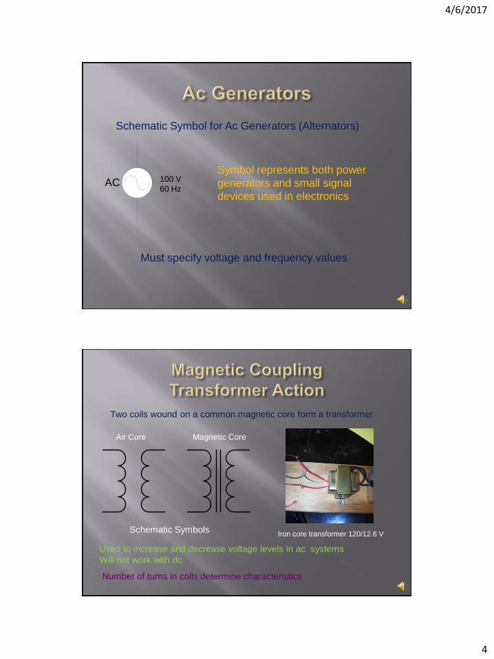
Schematic Symbol for Ac Generators (Alternators)
AC 100 V
60 Hz
Symbol represents both power
generators and small signal
devices used in electronics
Must specify voltage and frequency values
Two coils wound on a common magnetic core form a transformer
Number of turns in coils determine characteristics
Used to increase and decrease voltage levels in ac systems
Will not work with dc
Air Core Magnetic Core
Schematic Symbols Iron core transformer 120/12.6 V
4/6/2017
5
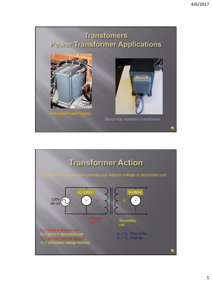
Industrial Power Supply
Bench-top Isolation Transformer
120V
60 HzV V
Magnetic field produced in primary coil induces voltage in secondary coil
Vp Vs
Primary
coil Secondary
coil
Vp=120 V Vs=60 V
Np = turns in primary coil
Ns = turns in secondary coil
Vp = primary voltage applied
Vs = secondary voltage induced
Vs < Vp Step-down
Vs > Vp Step-up
4/6/2017
6
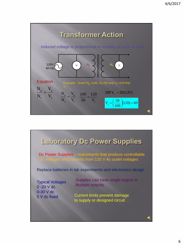
120V
60 HzV VNp Ns
Induced voltage is proportional to number of turns in coils
s
p
s
p
V
V
N
N
Equation Example: Given Np =100, Ns=50 and Vp=120 find
Vs
s
p
s
p
V
V
N
N
sV
120
50
100
)120(50V100 s
60)120(100
50Vs
Dc Power Supplies – Instruments that produce controllable
dc voltages and currents from 120 V Ac outlet voltages
Replace batteries in lab experiments and electronics design
Typical Voltages
0 -20 V dc
0-30 V dc
5 V dc fixed
Supplies can have single output or
Multiple outputs
Current limits prevent damage
to supply or designed circuit
4/6/2017
7
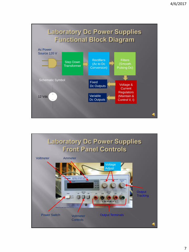
Step Down
Transformer
Rectifiers
(Ac to Dc
Conversion)
Filters
(Smooth
Pulsing Dc)
Voltage &
Current
Regulators
(Maintain &
Control V, I)
Ac Power
Source 120 V
Fixed
Dc Outputs
Variable
Dc Outputs
Schematic Symbol
12 Vdc
Power Switch
Voltmeter
Voltmeter
Controls
Output Terminals
Output
Tracking
Voltage
Adjust
Ammeter
4/6/2017
8
End Lesson 5 EET 150
Coming Next: Simple Circuit Analysis
Using Ohm’s Law