Embed Size (px)
Citation preview
Combining Battery and AC Sources for More Reliable Control Power
Edmund O. Schweitzer, III, David E. Whitehead, Michael Thompson, Krishnanjan Gubba Ravikumar, Austin Wade, Bruce Hall, and Sean Robertson
Schweitzer Engineering Laboratories, Inc.
Revised edition released May 2021
Previously presented at the 74th Annual Conference for Protective Relay Engineers, March 2021
Originally presented at the 47th Annual Western Protective Relay Conference, October 2020
1
Combining Battery and AC Sources for More Reliable Control Power
Edmund O. Schweitzer, III, David E. Whitehead, Michael Thompson, Krishnanjan Gubba Ravikumar, Austin Wade, Bruce Hall, and Sean Robertson, Schweitzer Engineering Laboratories, Inc.
Abstract—Technological advances have placed growing demands on control power for critical infrastructure. Station battery power used to be needed only for operating circuit breakers. Today it is different: the battery must also provide power to protective relays, meters, automation controllers, communications equipment, and computers. Even brief interruptions of control power are troublesome, as many devices have short ride-through times and long startup times. For example, a computer can take minutes to restart after a short interruption of power.
This paper presents a simple, yet novel approach to increasing the reliability of auxiliary dc control circuits by combining multiple sources and providing ride-through capabilities in the event of a loss of all input sources. The paper further highlights technical benefits and applications while showing how increased source diversity can improve the availability of dc control power for protection and control and mitigate the impact of failure or degradation of the auxiliary dc supply, as well as for tripping circuit breakers.
I. INTRODUCTION Historically, the auxiliary dc control power system (in this
paper referred to as the dc system) only had to provide power to breaker trip coils and panel indication lights. Electromechanical relays were only dependent on the power system secondary quantities to operate by employing electromagnetic attraction or induction to close the trip contacts. Today, it is different; the dc system must also provide power to various intelligent electronic devices (IEDs), such as protective relays, meters, automation controllers, communications equipment, GPS clocks, and computers. Unlike electromechanical relays, these devices are reliant on control power to operate. If the control power is lost or momentarily disrupted, the relay may take several seconds to restart and enable. Computers, automation controllers, and network switches take even longer to restart. With the increasing use of microprocessor-based relays, communications network-based protection schemes, and special protection and control schemes, the need for reliable control power has never been more critical.
The last several decades have seen multiple innovations in protective relaying, including microprocessor-based relays, new algorithms, increased speed, and reporting functions. However, in this same period, the dc system has seen few changes or innovation. In fact, if protection engineers from the 1950s were to enter a modern substation, they would see practically no changes in the dc system.
The dc system can easily be overlooked by protection engineers who are focused on understanding the power system
and apparatus to be protected, fault studies, and schematic design. Reliability may be assumed or ignored. This may be attributed to the division of ownership and/or responsibility of the dc system where a different department or group is responsible for the dc system and battery maintenance or an outside consultant deems the dc system outside the scope of a protection upgrade.
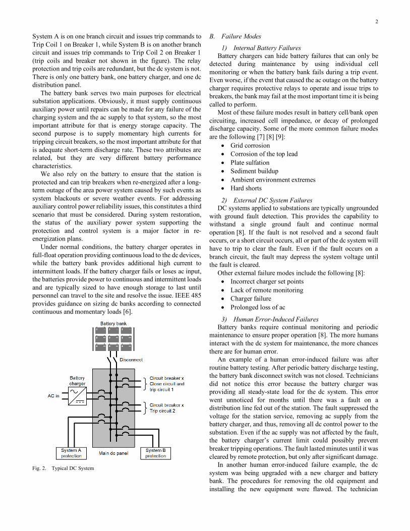
A single battery bank is often used due to the “relatively high cost of battery systems and the high reliability that experience has shown can be obtained … with good maintenance and monitoring practices” [1]. While the complete loss of the dc system may be a low-probability event, it can have extreme consequences. Failures in the dc system can result in significant equipment and property damage and possibly endanger human lives. Reference [2] provides an example where a dc system failed in a distribution substation, and remote backup relays were unable to detect the event. The result was a complete catastrophic loss of the substation. The event was captured on camera (see Fig. 1) and has since gained over 215,000 views on YouTube [3].
Fig. 1. Loss of a Substation Transformer After a DC System Failure
II. DC SYSTEMS, FAILURES, AND INTERRUPTIONS
A. DC System Overview We generally do not power protection and control systems
from the power system being protected because a short circuit on the power system can remove the source of control power at the time needed to isolate the fault. Thus, most electrical substations include a battery bank to supply auxiliary power.
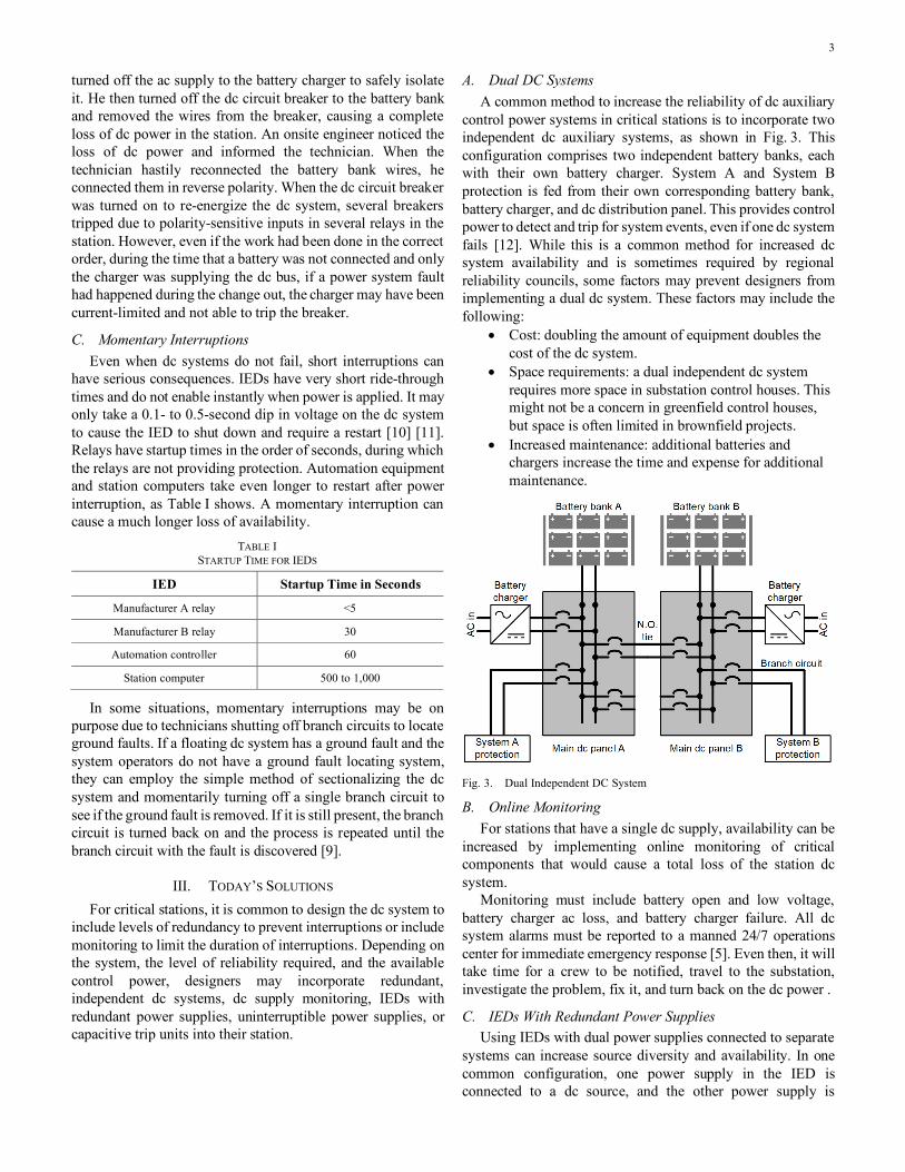
A typical dc system comprises dc supply and control circuitry. The dc supply includes a battery bank and charger. The dc control circuitry comprises a distribution panel, branch circuits, protective devices, and monitoring equipment [4] [5]. Fig. 2 shows a typical dc system with redundant protection.
2
System A is on one branch circuit and issues trip commands to Trip Coil 1 on Breaker 1, while System B is on another branch circuit and issues trip commands to Trip Coil 2 on Breaker 1 (trip coils and breaker not shown in the figure). The relay protection and trip coils are redundant, but the dc system is not. There is only one battery bank, one battery charger, and one dc distribution panel.
The battery bank serves two main purposes for electrical substation applications. Obviously, it must supply continuous auxiliary power until repairs can be made for any failure of the charging system and the ac supply to that system, so the most important attribute for that is energy storage capacity. The second purpose is to supply momentary high currents for tripping circuit breakers, so the most important attribute for that is adequate short-term discharge rate. These two attributes are related, but they are very different battery performance characteristics.
We also rely on the battery to ensure that the station is protected and can trip breakers when re-energized after a long-term outage of the area power system caused by such events as system blackouts or severe weather events. For addressing auxiliary control power reliability issues, this constitutes a third scenario that must be considered. During system restoration, the status of the auxiliary power system supporting the protection and control system is a major factor in re-energization plans.
Under normal conditions, the battery charger operates in full-float operation providing continuous load to the dc devices, while the battery bank provides additional high current to intermittent loads. If the battery charger fails or loses ac input, the batteries provide power to continuous and intermittent loads and are typically sized to have enough storage to last until personnel can travel to the site and resolve the issue. IEEE 485 provides guidance on sizing dc banks according to connected continuous and momentary loads [6].
Fig. 2. Typical DC System
B. Failure Modes
1) Internal Battery Failures Battery chargers can hide battery failures that can only be
detected during maintenance by using individual cell monitoring or when the battery bank fails during a trip event. Even worse, if the event that caused the ac outage on the battery charger requires protective relays to operate and issue trips to breakers, the bank may fail at the most important time it is being called to perform.
Most of these failure modes result in battery cell/bank open circuiting, increased cell impedance, or decay of prolonged discharge capacity. Some of the more common failure modes are the following [7] [8] [9]:
• Grid corrosion • Corrosion of the top lead • Plate sulfation • Sediment buildup • Ambient environment extremes • Hard shorts
2) External DC System Failures DC systems applied to substations are typically ungrounded
with ground fault detection. This provides the capability to withstand a single ground fault and continue normal operation [8]. If the fault is not resolved and a second fault occurs, or a short circuit occurs, all or part of the dc system will have to trip to clear the fault. Even if the fault occurs on a branch circuit, the fault may depress the system voltage until the fault is cleared.
Other external failure modes include the following [8]: • Incorrect charger set points • Lack of remote monitoring • Charger failure • Prolonged loss of ac
3) Human Error-Induced Failures Battery banks require continual monitoring and periodic
maintenance to ensure proper operation [8]. The more humans interact with the dc system for maintenance, the more chances there are for human error.
An example of a human error-induced failure was after routine battery testing. After periodic battery discharge testing, the battery bank disconnect switch was not closed. Technicians did not notice this error because the battery charger was providing all steady-state load for the dc system. This error went unnoticed for months until there was a fault on a distribution line fed out of the station. The fault suppressed the voltage for the station service, removing ac supply from the battery charger, and thus, removing all dc control power to the substation. Even if the ac supply was not affected by the fault, the battery charger’s current limit could possibly prevent breaker tripping operations. The fault lasted minutes until it was cleared by remote protection, but only after significant damage.
In another human error-induced failure example, the dc system was being upgraded with a new charger and battery bank. The procedures for removing the old equipment and installing the new equipment were flawed. The technician
3
turned off the ac supply to the battery charger to safely isolate it. He then turned off the dc circuit breaker to the battery bank and removed the wires from the breaker, causing a complete loss of dc power in the station. An onsite engineer noticed the loss of dc power and informed the technician. When the technician hastily reconnected the battery bank wires, he connected them in reverse polarity. When the dc circuit breaker was turned on to re-energize the dc system, several breakers tripped due to polarity-sensitive inputs in several relays in the station. However, even if the work had been done in the correct order, during the time that a battery was not connected and only the charger was supplying the dc bus, if a power system fault had happened during the change out, the charger may have been current-limited and not able to trip the breaker.
C. Momentary Interruptions Even when dc systems do not fail, short interruptions can
have serious consequences. IEDs have very short ride-through times and do not enable instantly when power is applied. It may only take a 0.1- to 0.5-second dip in voltage on the dc system to cause the IED to shut down and require a restart [10] [11]. Relays have startup times in the order of seconds, during which the relays are not providing protection. Automation equipment and station computers take even longer to restart after power interruption, as Table I shows. A momentary interruption can cause a much longer loss of availability.
TABLE I STARTUP TIME FOR IEDS
IED Startup Time in Seconds
Manufacturer A relay <5
Manufacturer B relay 30
Automation controller 60
Station computer 500 to 1,000
In some situations, momentary interruptions may be on purpose due to technicians shutting off branch circuits to locate ground faults. If a floating dc system has a ground fault and the system operators do not have a ground fault locating system, they can employ the simple method of sectionalizing the dc system and momentarily turning off a single branch circuit to see if the ground fault is removed. If it is still present, the branch circuit is turned back on and the process is repeated until the branch circuit with the fault is discovered [9].
III. TODAY’S SOLUTIONS For critical stations, it is common to design the dc system to
include levels of redundancy to prevent interruptions or include monitoring to limit the duration of interruptions. Depending on the system, the level of reliability required, and the available control power, designers may incorporate redundant, independent dc systems, dc supply monitoring, IEDs with redundant power supplies, uninterruptible power supplies, or capacitive trip units into their station.
A. Dual DC Systems A common method to increase the reliability of dc auxiliary
control power systems in critical stations is to incorporate two independent dc auxiliary systems, as shown in Fig. 3. This configuration comprises two independent battery banks, each with their own battery charger. System A and System B protection is fed from their own corresponding battery bank, battery charger, and dc distribution panel. This provides control power to detect and trip for system events, even if one dc system fails [12]. While this is a common method for increased dc system availability and is sometimes required by regional reliability councils, some factors may prevent designers from implementing a dual dc system. These factors may include the following:
• Cost: doubling the amount of equipment doubles the cost of the dc system.
• Space requirements: a dual independent dc system requires more space in substation control houses. This might not be a concern in greenfield control houses, but space is often limited in brownfield projects.
• Increased maintenance: additional batteries and chargers increase the time and expense for additional maintenance.
Fig. 3. Dual Independent DC System
B. Online Monitoring For stations that have a single dc supply, availability can be
increased by implementing online monitoring of critical components that would cause a total loss of the station dc system.
Monitoring must include battery open and low voltage, battery charger ac loss, and battery charger failure. All dc system alarms must be reported to a manned 24/7 operations center for immediate emergency response [5]. Even then, it will take time for a crew to be notified, travel to the substation, investigate the problem, fix it, and turn back on the dc power .
C. IEDs With Redundant Power Supplies Using IEDs with dual power supplies connected to separate
systems can increase source diversity and availability. In one common configuration, one power supply in the IED is connected to a dc source, and the other power supply is
4
connected to an ac source. This is often the case with automation and networking equipment. Requiring dual power supplies in each IED and has several downsides, such as the following:
• A second power supply in each IED increases the cost. • IEDs become inefficient, creating more heat in
equipment and control houses. • Not every IED supports dual power supplies. • Redundant power supplies in IEDs do not efficiently
or significantly address the common-mode failure problem of the loss of the dc source.
D. Capacitive Trip Units Some small or remote distribution stations do not have a dc
system and use fuses for power transformer protection and reclosers as distribution feeder breakers. These locations require that capacitive trip units (CTU) provide energy to energize trip coils in the case of a loss of ac control power. CTUs are also often used in industrial and mining facilities.
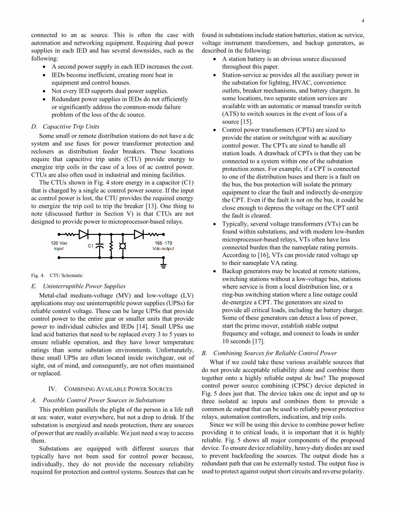
The CTUs shown in Fig. 4 store energy in a capacitor (C1) that is charged by a single ac control power source. If the input ac control power is lost, the CTU provides the required energy to energize the trip coil to trip the breaker [13]. One thing to note (discussed further in Section V) is that CTUs are not designed to provide power to microprocessor-based relays.
Fig. 4. CTU Schematic
E. Uninterruptible Power Supplies Metal-clad medium-voltage (MV) and low-voltage (LV)
applications may use uninterruptible power supplies (UPSs) for reliable control voltage. These can be large UPSs that provide control power to the entire gear or smaller units that provide power to individual cubicles and IEDs [14]. Small UPSs use lead acid batteries that need to be replaced every 3 to 5 years to ensure reliable operation, and they have lower temperature ratings than some substation environments. Unfortunately, these small UPSs are often located inside switchgear, out of sight, out of mind, and consequently, are not often maintained or replaced.
IV. COMBINING AVAILABLE POWER SOURCES
A. Possible Control Power Sources in Substations This problem parallels the plight of the person in a life raft
at sea: water, water everywhere, but not a drop to drink. If the substation is energized and needs protection, there are sources of power that are readily available. We just need a way to access them.
Substations are equipped with different sources that typically have not been used for control power because, individually, they do not provide the necessary reliability required for protection and control systems. Sources that can be
found in substations include station batteries, station ac service, voltage instrument transformers, and backup generators, as described in the following:
• A station battery is an obvious source discussed throughout this paper.
• Station-service ac provides all the auxiliary power in the substation for lighting, HVAC, convenience outlets, breaker mechanisms, and battery chargers. In some locations, two separate station services are available with an automatic or manual transfer switch (ATS) to switch sources in the event of loss of a source [15].
• Control power transformers (CPTs) are sized to provide the station or switchgear with ac auxiliary control power. The CPTs are sized to handle all station loads. A drawback of CPTs is that they can be connected to a system within one of the substation protection zones. For example, if a CPT is connected to one of the distribution buses and there is a fault on the bus, the bus protection will isolate the primary equipment to clear the fault and indirectly de-energize the CPT. Even if the fault is not on the bus, it could be close enough to depress the voltage on the CPT until the fault is cleared.
• Typically, several voltage transformers (VTs) can be found within substations, and with modern low-burden microprocessor-based relays, VTs often have less connected burden than the nameplate rating permits. According to [16], VTs can provide rated voltage up to their nameplate VA rating.
• Backup generators may be located at remote stations, switching stations without a low-voltage bus, stations where service is from a local distribution line, or a ring-bus switching station where a line outage could de-energize a CPT. The generators are sized to provide all critical loads, including the battery charger. Some of these generators can detect a loss of power, start the prime mover, establish stable output frequency and voltage, and connect to loads in under 10 seconds [17].
B. Combining Sources for Reliable Control Power What if we could take these various available sources that
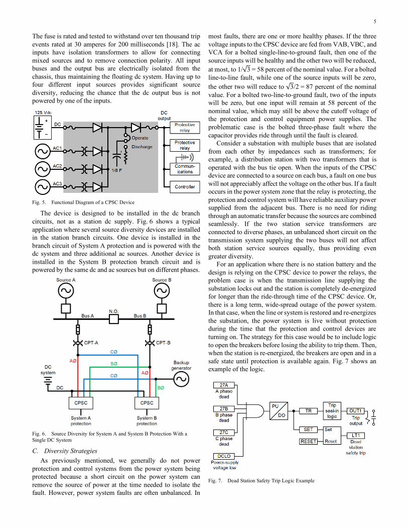
do not provide acceptable reliability alone and combine them together onto a highly reliable output dc bus? The proposed control power source combining (CPSC) device depicted in Fig. 5 does just that. The device takes one dc input and up to three isolated ac inputs and combines them to provide a common dc output that can be used to reliably power protective relays, automation controllers, indication, and trip coils.
Since we will be using this device to combine power before providing it to critical loads, it is important that it is highly reliable. Fig. 5 shows all major components of the proposed device. To ensure device reliability, heavy-duty diodes are used to prevent backfeeding the sources. The output diode has a redundant path that can be externally tested. The output fuse is used to protect against output short circuits and reverse polarity.
5
The fuse is rated and tested to withstand over ten thousand trip events rated at 30 amperes for 200 milliseconds [18]. The ac inputs have isolation transformers to allow for connecting mixed sources and to remove connection polarity. All input buses and the output bus are electrically isolated from the chassis, thus maintaining the floating dc system. Having up to four different input sources provides significant source diversity, reducing the chance that the dc output bus is not powered by one of the inputs.
Fig. 5. Functional Diagram of a CPSC Device
The device is designed to be installed in the dc branch circuits, not as a station dc supply. Fig. 6 shows a typical application where several source diversity devices are installed in the station branch circuits. One device is installed in the branch circuit of System A protection and is powered with the dc system and three additional ac sources. Another device is installed in the System B protection branch circuit and is powered by the same dc and ac sources but on different phases.
Fig. 6. Source Diversity for System A and System B Protection With a Single DC System
C. Diversity Strategies As previously mentioned, we generally do not power
protection and control systems from the power system being protected because a short circuit on the power system can remove the source of power at the time needed to isolate the fault. However, power system faults are often unbalanced. In
most faults, there are one or more healthy phases. If the three voltage inputs to the CPSC device are fed from VAB, VBC, and VCA for a bolted single-line-to-ground fault, then one of the source inputs will be healthy and the other two will be reduced, at most, to 1/√3 = 58 percent of the nominal value. For a bolted line-to-line fault, while one of the source inputs will be zero, the other two will reduce to √3/2 = 87 percent of the nominal value. For a bolted two-line-to-ground fault, two of the inputs will be zero, but one input will remain at 58 percent of the nominal value, which may still be above the cutoff voltage of the protection and control equipment power supplies. The problematic case is the bolted three-phase fault where the capacitor provides ride through until the fault is cleared.
Consider a substation with multiple buses that are isolated from each other by impedances such as transformers; for example, a distribution station with two transformers that is operated with the bus tie open. When the inputs of the CPSC device are connected to a source on each bus, a fault on one bus will not appreciably affect the voltage on the other bus. If a fault occurs in the power system zone that the relay is protecting, the protection and control system will have reliable auxiliary power supplied from the adjacent bus. There is no need for riding through an automatic transfer because the sources are combined seamlessly. If the two station service transformers are connected to diverse phases, an unbalanced short circuit on the transmission system supplying the two buses will not affect both station service sources equally, thus providing even greater diversity.
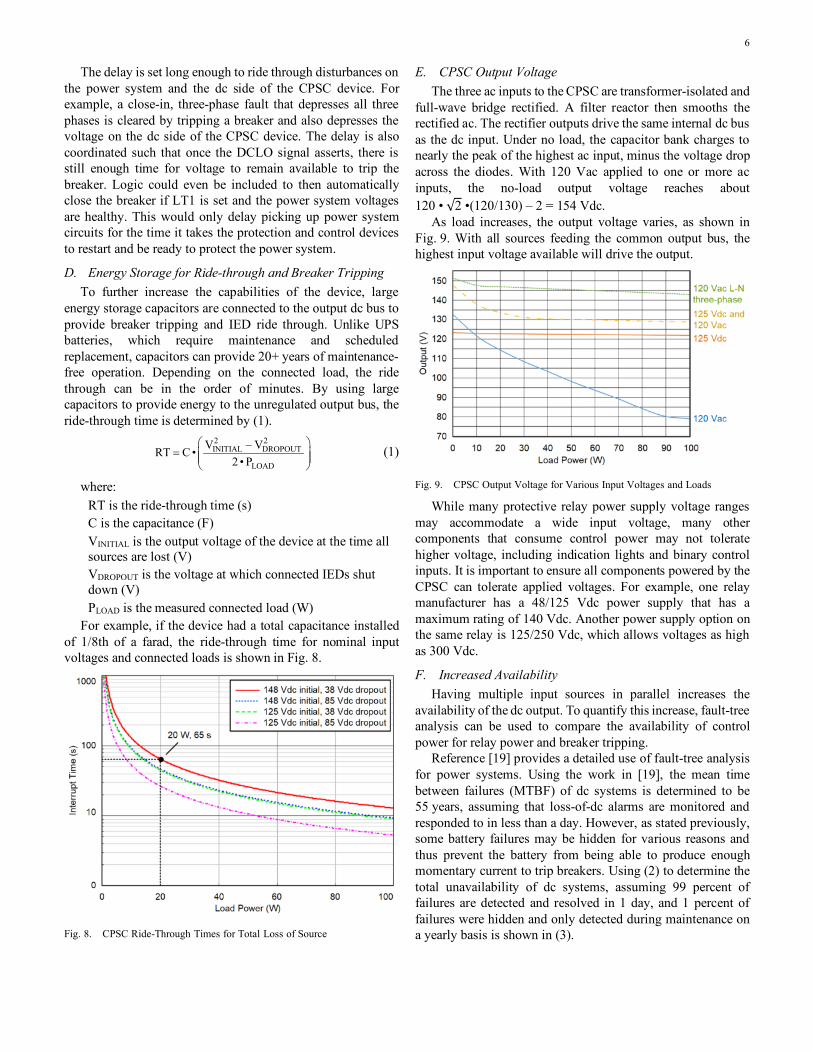
For an application where there is no station battery and the design is relying on the CPSC device to power the relays, the problem case is when the transmission line supplying the substation locks out and the station is completely de-energized for longer than the ride-through time of the CPSC device. Or, there is a long term, wide-spread outage of the power system. In that case, when the line or system is restored and re-energizes the substation, the power system is live without protection during the time that the protection and control devices are turning on. The strategy for this case would be to include logic to open the breakers before losing the ability to trip them. Then, when the station is re-energized, the breakers are open and in a safe state until protection is available again. Fig. 7 shows an example of the logic.
Fig. 7. Dead Station Safety Trip Logic Example
6
The delay is set long enough to ride through disturbances on the power system and the dc side of the CPSC device. For example, a close-in, three-phase fault that depresses all three phases is cleared by tripping a breaker and also depresses the voltage on the dc side of the CPSC device. The delay is also coordinated such that once the DCLO signal asserts, there is still enough time for voltage to remain available to trip the breaker. Logic could even be included to then automatically close the breaker if LT1 is set and the power system voltages are healthy. This would only delay picking up power system circuits for the time it takes the protection and control devices to restart and be ready to protect the power system.
D. Energy Storage for Ride-through and Breaker Tripping To further increase the capabilities of the device, large
energy storage capacitors are connected to the output dc bus to provide breaker tripping and IED ride through. Unlike UPS batteries, which require maintenance and scheduled replacement, capacitors can provide 20+ years of maintenance-free operation. Depending on the connected load, the ride through can be in the order of minutes. By using large capacitors to provide energy to the unregulated output bus, the ride-through time is determined by (1).
2 2INITIAL DROPOUT
LOAD
V VRT C •2 • P
−=
(1)
where: RT is the ride-through time (s) C is the capacitance (F) VINITIAL is the output voltage of the device at the time all sources are lost (V) VDROPOUT is the voltage at which connected IEDs shut down (V) PLOAD is the measured connected load (W)
For example, if the device had a total capacitance installed of 1/8th of a farad, the ride-through time for nominal input voltages and connected loads is shown in Fig. 8.
Fig. 8. CPSC Ride-Through Times for Total Loss of Source
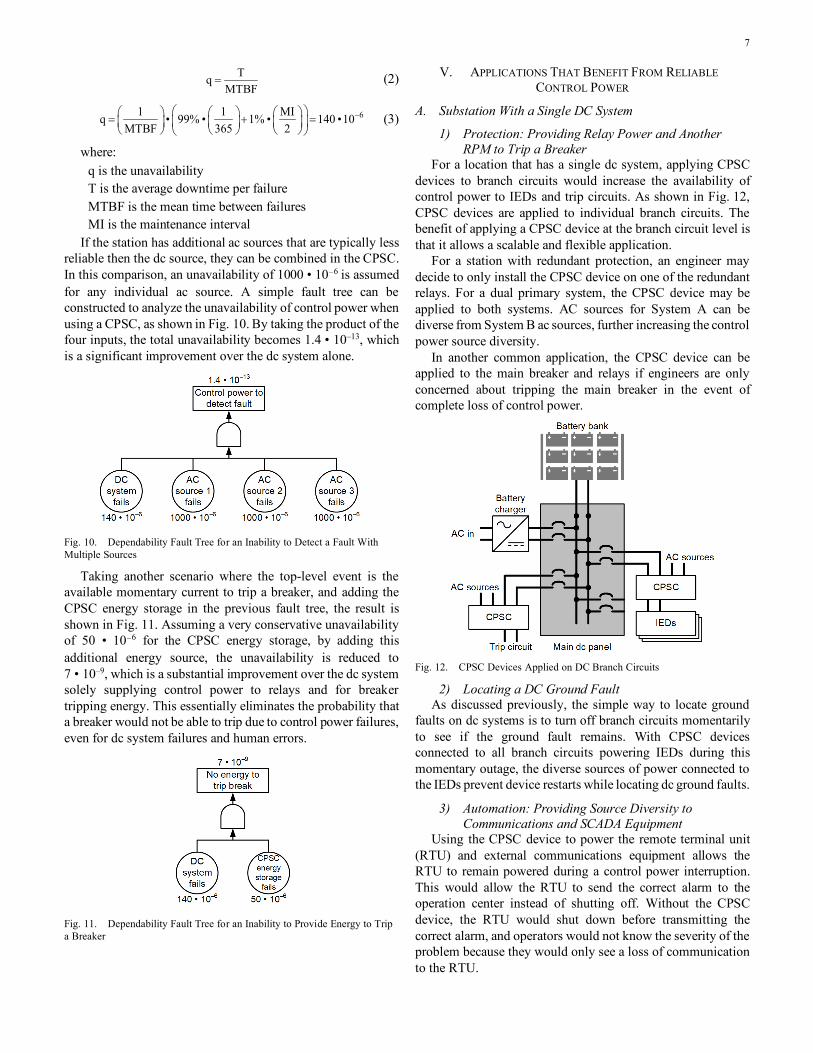
E. CPSC Output Voltage The three ac inputs to the CPSC are transformer-isolated and
full-wave bridge rectified. A filter reactor then smooths the rectified ac. The rectifier outputs drive the same internal dc bus as the dc input. Under no load, the capacitor bank charges to nearly the peak of the highest ac input, minus the voltage drop across the diodes. With 120 Vac applied to one or more ac inputs, the no-load output voltage reaches about 120 • √2 •(120/130) – 2 = 154 Vdc.
As load increases, the output voltage varies, as shown in Fig. 9. With all sources feeding the common output bus, the highest input voltage available will drive the output.
Fig. 9. CPSC Output Voltage for Various Input Voltages and Loads
While many protective relay power supply voltage ranges may accommodate a wide input voltage, many other components that consume control power may not tolerate higher voltage, including indication lights and binary control inputs. It is important to ensure all components powered by the CPSC can tolerate applied voltages. For example, one relay manufacturer has a 48/125 Vdc power supply that has a maximum rating of 140 Vdc. Another power supply option on the same relay is 125/250 Vdc, which allows voltages as high as 300 Vdc.
F. Increased Availability Having multiple input sources in parallel increases the
availability of the dc output. To quantify this increase, fault-tree analysis can be used to compare the availability of control power for relay power and breaker tripping.
Reference [19] provides a detailed use of fault-tree analysis for power systems. Using the work in [19], the mean time between failures (MTBF) of dc systems is determined to be 55 years, assuming that loss-of-dc alarms are monitored and responded to in less than a day. However, as stated previously, some battery failures may be hidden for various reasons and thus prevent the battery from being able to produce enough momentary current to trip breakers. Using (2) to determine the total unavailability of dc systems, assuming 99 percent of failures are detected and resolved in 1 day, and 1 percent of failures were hidden and only detected during maintenance on a yearly basis is shown in (3).
7
TqMTBF
= (2)
61 1 MIq • 99% • 1% • 140 •10MTBF 365 2
− = + =
(3)
where: q is the unavailability T is the average downtime per failure MTBF is the mean time between failures MI is the maintenance interval
If the station has additional ac sources that are typically less reliable then the dc source, they can be combined in the CPSC. In this comparison, an unavailability of 1000 • 10–6 is assumed for any individual ac source. A simple fault tree can be constructed to analyze the unavailability of control power when using a CPSC, as shown in Fig. 10. By taking the product of the four inputs, the total unavailability becomes 1.4 • 10–13, which is a significant improvement over the dc system alone.
Fig. 10. Dependability Fault Tree for an Inability to Detect a Fault With Multiple Sources
Taking another scenario where the top-level event is the available momentary current to trip a breaker, and adding the CPSC energy storage in the previous fault tree, the result is shown in Fig. 11. Assuming a very conservative unavailability of 50 • 10–6 for the CPSC energy storage, by adding this additional energy source, the unavailability is reduced to 7 • 10–9, which is a substantial improvement over the dc system solely supplying control power to relays and for breaker tripping energy. This essentially eliminates the probability that a breaker would not be able to trip due to control power failures, even for dc system failures and human errors.
Fig. 11. Dependability Fault Tree for an Inability to Provide Energy to Trip a Breaker
V. APPLICATIONS THAT BENEFIT FROM RELIABLE CONTROL POWER
A. Substation With a Single DC System
1) Protection: Providing Relay Power and Another RPM to Trip a Breaker
For a location that has a single dc system, applying CPSC devices to branch circuits would increase the availability of control power to IEDs and trip circuits. As shown in Fig. 12, CPSC devices are applied to individual branch circuits. The benefit of applying a CPSC device at the branch circuit level is that it allows a scalable and flexible application.
For a station with redundant protection, an engineer may decide to only install the CPSC device on one of the redundant relays. For a dual primary system, the CPSC device may be applied to both systems. AC sources for System A can be diverse from System B ac sources, further increasing the control power source diversity.
In another common application, the CPSC device can be applied to the main breaker and relays if engineers are only concerned about tripping the main breaker in the event of complete loss of control power.
Fig. 12. CPSC Devices Applied on DC Branch Circuits
2) Locating a DC Ground Fault As discussed previously, the simple way to locate ground
faults on dc systems is to turn off branch circuits momentarily to see if the ground fault remains. With CPSC devices connected to all branch circuits powering IEDs during this momentary outage, the diverse sources of power connected to the IEDs prevent device restarts while locating dc ground faults.
3) Automation: Providing Source Diversity to Communications and SCADA Equipment
Using the CPSC device to power the remote terminal unit (RTU) and external communications equipment allows the RTU to remain powered during a control power interruption. This would allow the RTU to send the correct alarm to the operation center instead of shutting off. Without the CPSC device, the RTU would shut down before transmitting the correct alarm, and operators would not know the severity of the problem because they would only see a loss of communication to the RTU.
8
B. Ride-Through Power for Generator Startup For substations that may have a backup generator, the CPSC
device could be used to ensure that protection and control equipment can ride through a loss-of-station-service event. If station service is lost, the CPSC devices could provide backup power to the battery bank while the generator starts up and provides power to the station.
C. Ride-Through Power for Station Service Reclose For a station that relies on station service from a source that
is subject to line trip and reclose events, the CPSC device can help increase reliability by providing another source of relay power supply energy and tripping current in the event the battery system fails; for example, a station fed from a radial subtransmission line, or a station that relies on a distribution line from another station to supply station service. Using (1) or Fig. 8, the protection ride through could be designed long enough to allow for the remote substation that is providing station services to reclose.
D. Battery Maintenance Periodic maintenance must be completed to ensure proper
operation and service life of substation battery banks. One periodic test is capacity testing. In this test, the bank may be isolated, a load applied, and discharge rates compared to a baseline [20]. Discharge testing can be time-consuming and can possibly introduce a failure into the dc system. For stations with dual dc systems, isolating a battery bank is relatively simple. In most of these installations there is a tie breaker between the two dc systems providing the ability to make a closed transition from two battery banks to a single bank [12].
For stations with a single dc system, this maintenance task is more difficult. To complete discharge testing, the sole battery bank must be disconnected from the rest of the system, which is a problem because most battery chargers are not rated to provide high momentary currents for tripping such as a bus trip event. If a fault occurs during this time, the battery charger may not provide enough current to actuate all required trip coils. This could endanger personnel and damage equipment. Even if the charger is rated to provide momentary load surges, the dc system is still vulnerable to the reliability of the ac supply to the battery charger.
To mitigate these risks, during battery maintenance on single dc systems, a portable battery bank is transported to the site and connected to the dc system prior to disconnecting the bank to be maintained. These portable banks can be as small as a cart or as large as a trailer weighing hundreds of pounds.
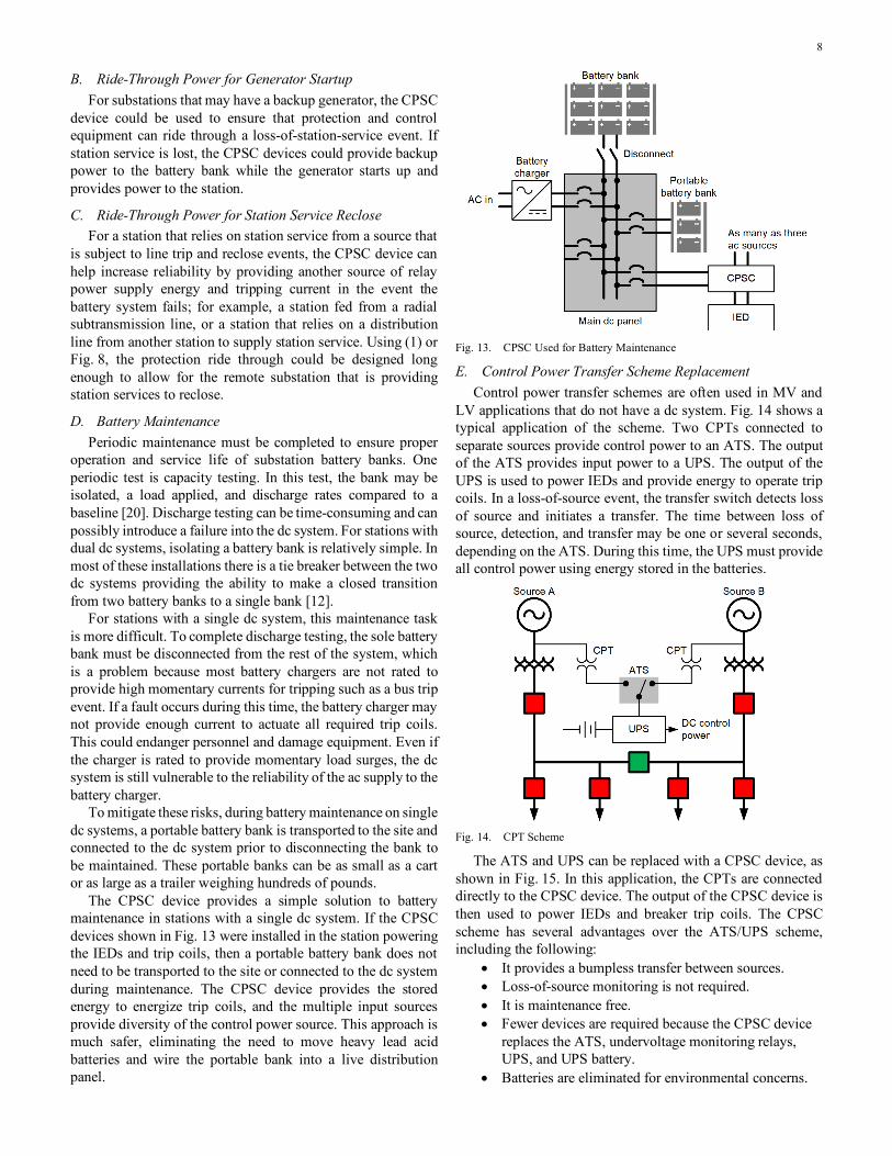
The CPSC device provides a simple solution to battery maintenance in stations with a single dc system. If the CPSC devices shown in Fig. 13 were installed in the station powering the IEDs and trip coils, then a portable battery bank does not need to be transported to the site or connected to the dc system during maintenance. The CPSC device provides the stored energy to energize trip coils, and the multiple input sources provide diversity of the control power source. This approach is much safer, eliminating the need to move heavy lead acid batteries and wire the portable bank into a live distribution panel.
Fig. 13. CPSC Used for Battery Maintenance
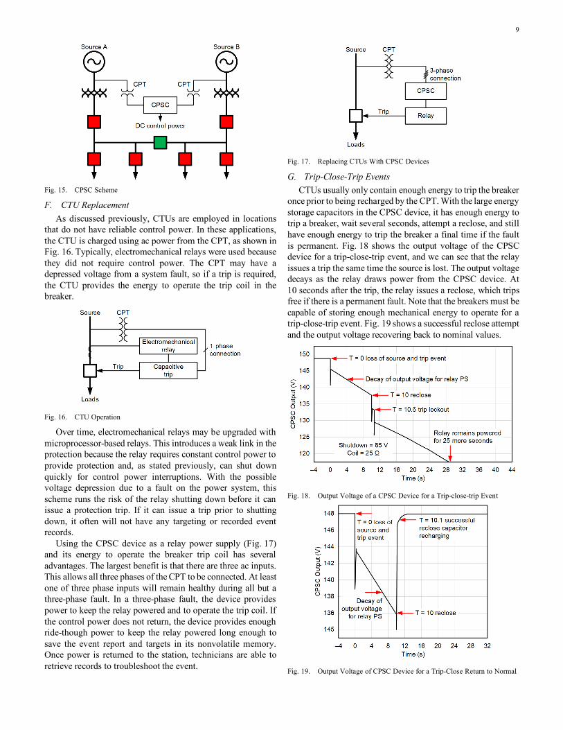
E. Control Power Transfer Scheme Replacement Control power transfer schemes are often used in MV and
LV applications that do not have a dc system. Fig. 14 shows a typical application of the scheme. Two CPTs connected to separate sources provide control power to an ATS. The output of the ATS provides input power to a UPS. The output of the UPS is used to power IEDs and provide energy to operate trip coils. In a loss-of-source event, the transfer switch detects loss of source and initiates a transfer. The time between loss of source, detection, and transfer may be one or several seconds, depending on the ATS. During this time, the UPS must provide all control power using energy stored in the batteries.
Fig. 14. CPT Scheme
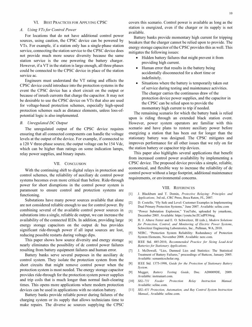
The ATS and UPS can be replaced with a CPSC device, as shown in Fig. 15. In this application, the CPTs are connected directly to the CPSC device. The output of the CPSC device is then used to power IEDs and breaker trip coils. The CPSC scheme has several advantages over the ATS/UPS scheme, including the following:
• It provides a bumpless transfer between sources. • Loss-of-source monitoring is not required. • It is maintenance free. • Fewer devices are required because the CPSC device
replaces the ATS, undervoltage monitoring relays, UPS, and UPS battery.
• Batteries are eliminated for environmental concerns.
9
Fig. 15. CPSC Scheme
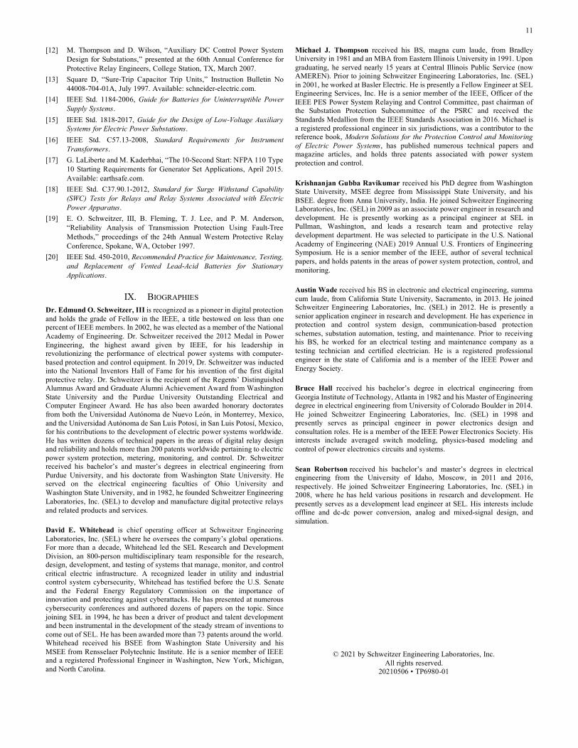
F. CTU Replacement As discussed previously, CTUs are employed in locations
that do not have reliable control power. In these applications, the CTU is charged using ac power from the CPT, as shown in Fig. 16. Typically, electromechanical relays were used because they did not require control power. The CPT may have a depressed voltage from a system fault, so if a trip is required, the CTU provides the energy to operate the trip coil in the breaker.
Fig. 16. CTU Operation
Over time, electromechanical relays may be upgraded with microprocessor-based relays. This introduces a weak link in the protection because the relay requires constant control power to provide protection and, as stated previously, can shut down quickly for control power interruptions. With the possible voltage depression due to a fault on the power system, this scheme runs the risk of the relay shutting down before it can issue a protection trip. If it can issue a trip prior to shutting down, it often will not have any targeting or recorded event records.
Using the CPSC device as a relay power supply (Fig. 17) and its energy to operate the breaker trip coil has several advantages. The largest benefit is that there are three ac inputs. This allows all three phases of the CPT to be connected. At least one of three phase inputs will remain healthy during all but a three-phase fault. In a three-phase fault, the device provides power to keep the relay powered and to operate the trip coil. If the control power does not return, the device provides enough ride-though power to keep the relay powered long enough to save the event report and targets in its nonvolatile memory. Once power is returned to the station, technicians are able to retrieve records to troubleshoot the event.
Fig. 17. Replacing CTUs With CPSC Devices
G. Trip-Close-Trip Events CTUs usually only contain enough energy to trip the breaker
once prior to being recharged by the CPT. With the large energy storage capacitors in the CPSC device, it has enough energy to trip a breaker, wait several seconds, attempt a reclose, and still have enough energy to trip the breaker a final time if the fault is permanent. Fig. 18 shows the output voltage of the CPSC device for a trip-close-trip event, and we can see that the relay issues a trip the same time the source is lost. The output voltage decays as the relay draws power from the CPSC device. At 10 seconds after the trip, the relay issues a reclose, which trips free if there is a permanent fault. Note that the breakers must be capable of storing enough mechanical energy to operate for a trip-close-trip event. Fig. 19 shows a successful reclose attempt and the output voltage recovering back to nominal values.
Fig. 18. Output Voltage of a CPSC Device for a Trip-close-trip Event
Fig. 19. Output Voltage of CPSC Device for a Trip-Close Return to Normal
10
VI. BEST PRACTICES FOR APPLYING CPSC
A. Using VTs for Control Power For locations that do not have additional control power
sources, using caution, the CPSC device can be powered by VTs. For example, if a station only has a single-phase station service, connecting the station service to the CPSC device does not provide much more source diversity because the same station service is the one powering the battery charger. However, if a VT in the station is large enough, all three phases could be connected to the CPSC device in place of the station service ac.
Engineers must understand the VT rating and effects the CPSC device could introduce into the protection systems in the event the CPSC device has a short circuit on the output or because of inrush currents that charge the capacitor. It may not be desirable to use the CPSC device on VTs that also are used for voltage-based protection schemes, especially high-speed protection schemes such as distance elements, unless loss-of-potential logic is also implemented.
B. Unregulated DC Output The unregulated output of the CPSC device requires
ensuring that all connected components can handle the voltage levels at the output of the device. For example, if connected to a 120 V three-phase source, the output voltage can be 154 Vdc, which can be higher than ratings on some indication lamps, relay power supplies, and binary inputs.
VII. CONCLUSION With the continuing shift to digital relays in protection and
control schemes, the reliability of auxiliary dc control power systems becomes even more critical than before. Ride-through power for short disruptions in the control power system is paramount to ensure control and protection systems are functioning.
Substations have many power sources available that alone are not considered reliable enough to use for control power. By combining several of the available control power sources in substations into a single, reliable dc output, we can increase the availability of the connected IEDs. In addition, providing large energy storage capacitors on the output dc bus provides significant ride-through power if all input sources are lost, reducing possible restarts during voltage dips.
This paper shows how source diversity and energy storage nearly eliminates the possibility of dc control power failures resulting from battery equipment failures and human error.
Battery banks serve several purposes in the auxiliary dc control system. They isolate the protection system from the short circuits that might remove control power when the protection system is most needed. The energy storage capacitor provides ride-through for the protection system power supplies and trip coils that is much longer than normal fault-clearing times. This opens more applications where modern protection devices can be used in applications with no station battery.
Battery banks provide reliable power during failures of the charging system or its supply that allows technicians time to make repairs. The diverse ac sources supplying the CPSC
covers this scenario. Control power is available as long as the station is energized, even if the charger or its supply is not available.
Battery banks provide momentary high current for tripping breakers that the charger cannot be relied upon to provide. The energy storage capacitor of the CPSC provides this as well. This mitigates the following issues:
• Hidden battery failures that might prevent it from providing high current.
• Human error that results in the battery being accidentally disconnected for a short time or indefinitely.
• Situations where the battery is temporarily taken out of service during testing and maintenance activities. The charger carries the continuous draw of the protection device power supplies, and the capacitor in the CPSC can be relied upon to provide the momentary high current to trip if needed.
The remaining scenario for which the battery bank is relied upon is riding through an extended black station event. However, power system operators are familiar with this scenario and have plans to restore auxiliary power before energizing a station that has been out for longer than the stationary battery was designed. The CPSC mitigates and improves performance for all other issues that we rely on for the station battery or capacitor trip devices.
This paper also highlights several applications that benefit from increased control power availability by implementing a CPSC device. The proposed device provides a simple, reliable, economical, and flexible way to increase the reliability of dc control power without a large footprint, additional maintenance requirements, or environmental concerns.
VIII. REFERENCES [1] J. Blackburn and T. Domin, Protective Relaying: Principles and
Applications, 3rd ed., CRC Press, Boca Raton, FL, 2007. [2] D. Costello, “Fly Safe and Level: Customer Examples in Implementing
Dual Primary Protection Systems,” June 2007. Available: selinc.com [3] “Power Substation Explosion,” YouTube, uploaded by ymarkone,
December 2005. Available: https://youtu.be/ZCzdPFJ4tog. [4] H. J. Altuve Ferrer and E. O. Schweitzer, III (eds.), Modern Solutions
for Protection, Control, and Monitoring of Electric Power Systems, Schweitzer Engineering Laboratories, Inc., Pullman, WA, 2010.
[5] NERC, “Protection System Reliability: Redundancy of Protection System Elements, November 2008. Available: nerc.com.
[6] IEEE Std. 485-2010, Recommended Practice for Sizing Lead-Acid Batteries for Stationary Applications.
[7] J. McDowall, “Lies, Damned Lies and Statistics: The Statistical Treatment of Battery Failures,” proceedings of Battcon, January 2005. Available: semanticscholar.org.
[8] IEEE Std. 1375-1998, Guide for the Protection of Stationary Battery System.
[9] Megger, Battery Testing Guide, Doc. AD0009DE, 2009. Available: instrumart.com.
[10] SEL-751 Feeder Protection Relay Instruction Manual. Available: selinc.com.
[11] SEL-451 Protection, Automation, and Bay Control System Instruction Manual,. Available: selinc.com.
11
[12] M. Thompson and D. Wilson, “Auxiliary DC Control Power System Design for Substations,” presented at the 60th Annual Conference for Protective Relay Engineers, College Station, TX, March 2007.
[13] Square D, “Sure-Trip Capacitor Trip Units,” Instruction Bulletin No 44008-704-01A, July 1997. Available: schneider-electric.com.
[14] IEEE Std. 1184-2006, Guide for Batteries for Uninterruptible Power Supply Systems.
[15] IEEE Std. 1818-2017, Guide for the Design of Low-Voltage Auxiliary Systems for Electric Power Substations.
[16] IEEE Std. C57.13-2008, Standard Requirements for Instrument Transformers.
[17] G. LaLiberte and M. Kaderbhai, “The 10-Second Start: NFPA 110 Type 10 Starting Requirements for Generator Set Applications, April 2015. Available: earthsafe.com.
[18] IEEE Std. C37.90.1-2012, Standard for Surge Withstand Capability (SWC) Tests for Relays and Relay Systems Associated with Electric Power Apparatus.
[19] E. O. Schweitzer, III, B. Fleming, T. J. Lee, and P. M. Anderson, “Reliability Analysis of Transmission Protection Using Fault-Tree Methods,” proceedings of the 24th Annual Western Protective Relay Conference, Spokane, WA, October 1997.
[20] IEEE Std. 450-2010, Recommended Practice for Maintenance, Testing, and Replacement of Vented Lead-Acid Batteries for Stationary Applications.
IX. BIOGRAPHIES Dr. Edmund O. Schweitzer, III is recognized as a pioneer in digital protection and holds the grade of Fellow in the IEEE, a title bestowed on less than one percent of IEEE members. In 2002, he was elected as a member of the National Academy of Engineering. Dr. Schweitzer received the 2012 Medal in Power Engineering, the highest award given by IEEE, for his leadership in revolutionizing the performance of electrical power systems with computer-based protection and control equipment. In 2019, Dr. Schweitzer was inducted into the National Inventors Hall of Fame for his invention of the first digital protective relay. Dr. Schweitzer is the recipient of the Regents’ Distinguished Alumnus Award and Graduate Alumni Achievement Award from Washington State University and the Purdue University Outstanding Electrical and Computer Engineer Award. He has also been awarded honorary doctorates from both the Universidad Autónoma de Nuevo León, in Monterrey, Mexico, and the Universidad Autónoma de San Luis Potosí, in San Luis Potosí, Mexico, for his contributions to the development of electric power systems worldwide. He has written dozens of technical papers in the areas of digital relay design and reliability and holds more than 200 patents worldwide pertaining to electric power system protection, metering, monitoring, and control. Dr. Schweitzer received his bachelor’s and master’s degrees in electrical engineering from Purdue University, and his doctorate from Washington State University. He served on the electrical engineering faculties of Ohio University and Washington State University, and in 1982, he founded Schweitzer Engineering Laboratories, Inc. (SEL) to develop and manufacture digital protective relays and related products and services.
David E. Whitehead is chief operating officer at Schweitzer Engineering Laboratories, Inc. (SEL) where he oversees the company’s global operations. For more than a decade, Whitehead led the SEL Research and Development Division, an 800-person multidisciplinary team responsible for the research, design, development, and testing of systems that manage, monitor, and control critical electric infrastructure. A recognized leader in utility and industrial control system cybersecurity, Whitehead has testified before the U.S. Senate and the Federal Energy Regulatory Commission on the importance of innovation and protecting against cyberattacks. He has presented at numerous cybersecurity conferences and authored dozens of papers on the topic. Since joining SEL in 1994, he has been a driver of product and talent development and been instrumental in the development of the steady stream of inventions to come out of SEL. He has been awarded more than 73 patents around the world. Whitehead received his BSEE from Washington State University and his MSEE from Rensselaer Polytechnic Institute. He is a senior member of IEEE and a registered Professional Engineer in Washington, New York, Michigan, and North Carolina.
Michael J. Thompson received his BS, magna cum laude, from Bradley University in 1981 and an MBA from Eastern Illinois University in 1991. Upon graduating, he served nearly 15 years at Central Illinois Public Service (now AMEREN). Prior to joining Schweitzer Engineering Laboratories, Inc. (SEL) in 2001, he worked at Basler Electric. He is presently a Fellow Engineer at SEL Engineering Services, Inc. He is a senior member of the IEEE, Officer of the IEEE PES Power System Relaying and Control Committee, past chairman of the Substation Protection Subcommittee of the PSRC and received the Standards Medallion from the IEEE Standards Association in 2016. Michael is a registered professional engineer in six jurisdictions, was a contributor to the reference book, Modern Solutions for the Protection Control and Monitoring of Electric Power Systems, has published numerous technical papers and magazine articles, and holds three patents associated with power system protection and control.
Krishnanjan Gubba Ravikumar received his PhD degree from Washington State University, MSEE degree from Mississippi State University, and his BSEE. degree from Anna University, India. He joined Schweitzer Engineering Laboratories, Inc. (SEL) in 2009 as an associate power engineer in research and development. He is presently working as a principal engineer at SEL in Pullman, Washington, and leads a research team and protective relay development department. He was selected to participate in the U.S. National Academy of Engineering (NAE) 2019 Annual U.S. Frontiers of Engineering Symposium. He is a senior member of the IEEE, author of several technical papers, and holds patents in the areas of power system protection, control, and monitoring.
Austin Wade received his BS in electronic and electrical engineering, summa cum laude, from California State University, Sacramento, in 2013. He joined Schweitzer Engineering Laboratories, Inc. (SEL) in 2012. He is presently a senior application engineer in research and development. He has experience in protection and control system design, communication-based protection schemes, substation automation, testing, and maintenance. Prior to receiving his BS, he worked for an electrical testing and maintenance company as a testing technician and certified electrician. He is a registered professional engineer in the state of California and is a member of the IEEE Power and Energy Society.
Bruce Hall received his bachelor’s degree in electrical engineering from Georgia Institute of Technology, Atlanta in 1982 and his Master of Engineering degree in electrical engineering from University of Colorado Boulder in 2014. He joined Schweitzer Engineering Laboratories, Inc. (SEL) in 1998 and presently serves as principal engineer in power electronics design and consultation roles. He is a member of the IEEE Power Electronics Society. His interests include averaged switch modeling, physics-based modeling and control of power electronics circuits and systems.
Sean Robertson received his bachelor’s and master’s degrees in electrical engineering from the University of Idaho, Moscow, in 2011 and 2016, respectively. He joined Schweitzer Engineering Laboratories, Inc. (SEL) in 2008, where he has held various positions in research and development. He presently serves as a development lead engineer at SEL. His interests include offline and dc-dc power conversion, analog and mixed-signal design, and simulation.
© 2021 by Schweitzer Engineering Laboratories, Inc. All rights reserved.
20210506 • TP6980-01