Embed Size (px)
Citation preview
Regional Telecom Training Centre, BSNL-Hyderabad B.Tech Project Abstracts 2019-20
Page 1 of 32 continued…
ABSTRACT of Project No. 1
Convergence of IPv6 Network through IPv4 Network
Importance of Network.
The Internet is a worldwide publicly accessible system of interconnected computer
networks, since IPV4 in network enables data sharing between two or more computers,
which minimize time and energy wastages.
Limitation. The existing IPv4 network has the following limitations
� More latency,
� Less security
� Less address space and
� No auto configuration facility.
Proposed system: IPv6 network is proposed in this in these projects that overcomes all the limitation
available in existing network
Hardware: � Host, Switches and Routers
Software: � System software-Router ver 12.2 and Host – OS ver. window 7
� Simulation software – GNS-3 and
Problem definition When any organization wants to implement ipv6 network in his service area, it is
not possible to implement all of sudden in entire area. It needs slowly migration from ipv4
to ipv6 without much affecting service.
Solution: The Dual stack and tunneling concept is proposed in this project to transmit IPv6
packet through IPv4 Network that enables and achieves fully convergence in IPv6 network.
Future scope This concept involves less nos. of commands and it is very simple to configure and
not add any extra cost. So all network developer may use this concept
Regional Telecom Training Centre, BSNL-Hyderabad B.Tech Project Abstracts 2019-20
Page 2 of 32 continued…
ABSTRACT of Project No. 2
Implementation of IPv6 Internet services (6PE) over existing MPLS Network
Importance of Network.
This project work is about implementation of IPV6 in MPLS network. As the IPv6
has been deployed in the Internet core networks and many content providers provide
service using the new protocol, various Internet Service Providers (ISPs) are lifted behind
due to the high cost of migration especially for MPLS core. Therefore, the Internet
Engineering Task force provides a solution to be utilized during the transition period, which
is 6PE. This method treats IPv6 as a label in MPLS routing and can achieve rapid
deployment without any change in the core network.
Proposed system: 6PE offers the following benefits to service providers:
1. Minimal operational cost and risk:
� No impact on existing IPv4 and MPLS services
� Only provider edge routers require upgrade
� A 6PE router can be an existing PE router or a new one dedicated to IPv6
traffic.
2. No impact on IPv6 customer edge (CE) routers. The ISP can connect to any
CE router running Static, IGP or EGP.
3. Production services ready. An ISP can delegate IPv6 prefixes.
Problem definition IPv6 introduction into existing MPLS service—6PE routers can be added at any
time. This feature relies heavily on multiprotocol Border Gateway Protocol (BGP)
extensions in the IPv4 network configuration on the provider edge (PE) router to
exchange IPv6 reachability information (in addition to an MPLS label) for each IPv6
address prefix. Edge routers are configured as dual-stack, running both IPv4 and IPv6,
and use the IPv4 mapped IPv6 address for IPv6 prefix reachability exchange.
Solution:
The objective of this project is how ISPs implement 6PE services to customers by
designing a small ISP network using a GNS3 software tool.
Regional Telecom Training Centre, BSNL-Hyderabad B.Tech Project Abstracts 2019-20
Page 3 of 32 continued…
ABSTRACT of Project No. 3
Implementation of MPLS L2 VPN
Importance of Network. MPLS technology is being widely adopted by service providers worldwide to implement
VPNs to connect geographically separated customer sites. VPNs were originally introduced to
enable service providers to use common physical infrastructure to implement emulated point-to-
point links between customer sites. A customer network implemented with any VPN technology
would contain distinct regions under the customer's control called the customer sites connected
to each other via the service provider network.
Limitation. In traditional router based networks, different sites belonging to the same customer were
connected to each other using dedicated point-to-point links. The cost of implementation
depended on the number of customer sites to be connected with these dedicated links. A full
mesh of connected sites would consequently imply an exponential increase in the cost
associated. Frame Relay and ATM were the first technologies widely adopted to implement
VPNs. These networks consisted of various devices, belonging to either the customer or the
service provider, that were components of the VPN solution.
Proposed system: Depending on the service provider's participation in customer routing, the VPN
implementations can be classified broadly into one of the following Overlay model, Peer-to-peer
model.
The Service Provider initially implemented overlay VPNs by providing either Layer 1
(physical layer) connectivity or a Layer 2 transport circuit between customer sites. In the
Layer 1 implementation, the Service Provider would provide physical layer connectivity between
customer sites, and the customer was responsible for all other layers. In the Layer 2
implementation the Service Provider was responsible for transportation of Layer 2 frames (or
cells) between customer sites, which was traditionally implemented using either Frame Relay or
ATM switches as Provider Edge devices.
Layer2 VPNs implemented on MPLS backbone of service providers are referred as
“MPLS L2 VPNs” or AToM (Any Transport over MPLS). The implementation of MPLS L2
VPNs can be done in point to point (Virtual Private Wire Service) and point to multi point
configuration (Virtual Private LAN Service). Implementation of AToM can be like to like circuits
or any to any circuits. Customers when sending traffic can use any of the technologies like
Ethernet, Frame Relay, ATM, PPP, HDLC etc layer-2 switching technologies and service
providers create different virtual circuits accordingly with the technology implemented for the sites
connectivity of the customers in the service provider routers for optimal paths.
Practical / Hands-on: In this project trainee will do the following:
1. A small ISP network and customer network with few number of routers.
2. Configure the Routing protocols, MPLS in that ISP network routers.
3. Configure VPN customer branch routing at different locations towards service
provider domain.
4. Configure VPN customer in ISP routers and check for end-to-end connectivity of
the branches.
Trainee can simulate the network with software tool: GNS3
Regional Telecom Training Centre, BSNL-Hyderabad B.Tech Project Abstracts 2019-20
Page 4 of 32 continued…
ABSTRACT of Project No. 4
MPLS Traffic Engineering
Importance of Network. Multiprotocol Label Switching (MPLS) has evolved from being a buzzword in the
networking industry to a widely deployed technology in service provider (SP) networks.
MPLS is a contemporary solution to address a multitude of problems faced by present-day
networks: speed, scalability, quality of service (QoS) management, and traffic engineering.
Traffic Engineering is the process of steering traffic across to the backbone to
facilitate efficient use of available bandwidth between a pair of routers. Prior to MPLS TE,
traffic engineering was performed either by IP or by ATM, depending on the protocol in
use between two edge routers in a network. Though the term "traffic engineering" has
attained popularity and is used more in the context of MPLS TE today, traditional TE in IP
networks was performed either by IP or by ATM.TE with IP was mostly implemented by
manipulation of interface cost when multiple paths existed between two endpoints in the
network.
MPLS uses extensions to a link-state based Interior Gateway Protocol (IGP), such
as Intermediate System-to-Intermediate System (IS-IS) or Open Shortest Path First
(OSPF). MPLS calculates TE tunnels at the LSP head based on required and available
resources (constraint-based routing). If configured, the IGP automatically routes the traffic
onto these LSPs. Typically, a packet that crosses the MPLS TE backbone travels on a
single LSP that connects the ingress point to the egress point. MPLS TE automatically
establishes and maintains the LSPs across the MPLS network by using the
Resource Reservation Protocol (RSVP).
Proposed system: MPLS TE does the following-
� Source-based routing is applied to the traffic from the headend router (source of
MPLS TE tunnel). An explicitly defined path can be configured on the headend
router through which the traffic for a particular LSP must follow.
� MPLS TE provides efficient way of forwarding traffic throughout the network,
avoiding over-utilized and under-utilized links.
� MPLS TE adapts to changing bandwidth.
� MPLS TE takes into account configured bandwidth of the links.
Practical / Hands-on: In this project the trainee will be doing the following tasks with GNS3 software:
1. Design an ISP network with few Routers.
2. Configuring the IP addresses on the LAN / WAN interfaces.
3. Configuring and verification of Routing Protocol.
4. Configuring & verification of MPLS in ISP Routers.
5. Establishing and verifying the connectivity from Customer to ISP network.
6. Configuring a customer in MPLS domain of the ISP.
7. Creating the Traffic Engineering Tunnels in the ISP Routers with RSVP Protocol.
8. Verification of the Tunnels formation & load balancing etc.
Regional Telecom Training Centre, BSNL-Hyderabad B.Tech Project Abstracts 2019-20
Page 5 of 32 continued…
ABSTRACT of Project No. 5
Inter provider VPN
Importance of Network. MPLS technology is being widely adopted by service providers worldwide to implement VPNs
to connect geographically separated customer sites. VPNs were originally introduced to enable
service providers to use common physical infrastructure to implement emulated point-to-point links
between customer sites. A customer network implemented with any VPN technology would contain
distinct regions under the customer's control called the customer sites connected to each other via
the service provider network.
Limitation. In traditional router based networks, different sites belonging to the same customer were
connected to each other using dedicated point-to-point links. The cost of implementation depended
on the number of customer sites to be connected with these dedicated links. A full mesh of
connected sites would consequently imply an exponential increase in the cost associated. Frame
Relay and ATM were the first technologies widely adopted to implement VPNs. These networks
consisted of various devices, belonging to either the customer or the service provider, that were
components of the VPN solution. Depending on the service provider's participation in customer
routing, the VPN implementations can be classified broadly into one of the following Overlay model,
Peer-to-peer model.
Overlay VPNs were initially implemented by the Service Provider by providing either Layer 1
(physical layer) connectivity or a Layer 2 transport circuit between customer sites. In the Layer 1
implementation, the Service Provider would provide physical layer connectivity between customer
sites, and the customer was responsible for all other layers. In the Layer 2 implementation the
Service Provider was responsible for transportation of Layer 2 frames (or cells) between customer
sites, which was traditionally implemented using either Frame Relay or ATM switches as Provider
Edge devices.
Proposed system: The peer-to-peer model was developed to overcome the drawbacks of the Overlay model
and provide customers with optimal data transport via the Service Provider backbone. Hence, the
service provider would actively participate in customer routing. In the peer-to-peer model, routing
information is exchanged between the customer routers and the service provider routers, and
customer data is transported across the service provider's core, optimally. Customer routing
information is carried between routers in the provider network and customer network The peer-to-
peer model, consequently, does not require the creation of virtual circuits.
Practical / Hands-on: Inter-Provider VPN using BACK TO BACK VRF METHOD with GNS3 software:
The VRF-to-VRF approach is the simplest method for allowing MPLS VPN providers to
exchange VPN routing information for CE sites in different MPLS domains. In this approach, the
border provider edge (PE) routers residing in different autonomous systems function as ASBRs.
These ASBRs are interconnected either via a single link consisting of logical sub-interfaces or via
multiple physical links. VRFs are configured on the ASBRs to collect VPN client routes. Each sub-
interface or interface connected between the ASBRs is dedicated to a single client VRF. The single
client VRF can run eBGP, RIPv2, EIGRP, OSPF, or static routing to distribute the VPN routes to
its adjacent peer. The use of eBGP is, however, the most common in back-to-back VRF method
because eBGP scales best to this type of application, retaining the type of the route and offering
better policy, scalability, and security mechanisms. In this method, the LSP paths in adjacent MPLS
VPN autonomous systems are interconnected using the IP forwarding mechanism between the AS
border routers.
Regional Telecom Training Centre, BSNL-Hyderabad B.Tech Project Abstracts 2019-20
Page 6 of 32 continued…
ABSTRACT of Project No. 6
Implementation IPv6 VPN Services (6VPE) over MPLS
Importance of Network. This project work is about implementation of IPV6 in MPLS network. As the IPv6
has been deployed in the Internet core networks and many content providers provide
service using the new protocol, various Internet Service Providers (ISPs) are lifted behind
due to the high cost of migration especially for MPLS core. Therefore, the Internet
Engineering Task force provides a solution to be utilized during the transition period, which
is 6PE. This method treats IPv6 as a label in MPLS routing and can achieve rapid
deployment without any change in the core network.
Proposed system: 6VPE offers the following benefits to service providers:
1. Minimal operational cost and risk:
� No impact on existing IPv4 and MPLS services
� Only provider edge routers require upgrade
� A 6PE and 6VPE router can be an existing PE router or a new one
dedicated to IPv6 traffic.
2. No impact on IPv6 customer edge (CE) routers. The ISP can connect to any
CE router running Static, IGP or EGP.
3. Production services ready. An ISP can delegate IPv6 prefixes.
Problem definition
IPv6 introduction into an existing MPLS service?? 6PE routers can be added at
any time. This feature relies heavily on multiprotocol Border Gateway Protocol (BGP)
extensions in the IPv4 network configuration on the provider edge (PE) router to
exchange IPv6 reachability information (in addition to an MPLS label) for each IPv6
address prefix. Edge routers are configured as dual-stack, running both IPv4 and IPv6,
and use the IPv4 mapped IPv6 address for IPv6 prefix reachability exchange. 6PE offers
Internet services to the customers, then is VPN services can be offered to customers on
Ipv6??
Solution:
6VPE is the Virtual Private Netowrk (VPN) service offered by ISP using 6PE
network. ISP will l assign Unique local addresses to the different branches of Customers
and route between their branches using the dual stack routers placed at their edge
network. The objective of this project is how ISPs implement 6VPE services to customers
by designing a small ISP network using a GNS3 software tool.

Regional Telecom Training Centre, BSNL-Hyderabad B.Tech Project Abstracts 2019-20
Page 7 of 32 continued…
ABSTRACT of Project No. 7
Implementation of VPLS over MPLS
Importance of Network. Virtual Private LAN Services (VPLS) enables enterprises to link together their
Ethernet-based LANs from multiple sites via the infrastructure provided by their service
provider. From the enterprise perspective, the service provider’s public network looks like
one giant Ethernet LAN. For the service provider, VPLS provides an opportunity to deploy
another revenue-generating service on top of the existing network without major capital
expenditures. Operators can extend the operational life of equipment in their network. VPLS
uses the provider core to join multiple attachment circuits together to simulate a virtual
bridge that connects the multiple attachment circuits together. From a customer point of
view, there is no topology for VPLS. All customer edge (CE) devices appear to connect
to a logical bridge emulated by the provider core.
Proposed system: In this project trainee will do the following:
1. A small ISP network and customer network with few number of routers.
2. Configure the Routing protocols, MPLS in that ISP network routers.
3. Configure VPN customer branch routing at different locations towards service
provider domain.
4. Using Oracle Virtual Box Software creates a VM of CSR-1000V Router and
configure the VPLS.
5. Check the outputs & Results
Practical / Hands-on: � Trainee can simulate the network with software tool: GNS3, Oracle Vbox,
CSR-1000V
� Requirement: PC with 8 GB RAM Compulsory
Regional Telecom Training Centre, BSNL-Hyderabad B.Tech Project Abstracts 2019-20
Page 8 of 32 continued…
ABSTRACT of Project No. 8
Implementing Layer 3 VPNs over Layer 2 VPN Topologies and
Providing L2 VPN Redundancy
Importance of Network. MPLS technology is being widely adopted by service providers worldwide to
implement VPNs to connect geographically separated customer sites. VPNs were originally
introduced to enable service providers to use common physical infrastructure to implement
emulated point-to-point links between customer sites. A customer network implemented with
any VPN technology would contain distinct regions under the customer's control called the
customer sites connected to each other via the service provider network.
Limitation. In traditional router based networks, different sites belonging to the same customer
were connected to each other using dedicated point-to-point links. The cost of
implementation depended on the number of customer sites to be connected with these
dedicated links. A full mesh of connected sites would consequently imply an exponential
increase in the cost associated. Frame Relay and ATM were the first technologies widely
adopted to implement VPNs. These networks consisted of various devices, belonging to
either the customer or the service provider, that were components of the VPN solution.
Proposed system: Depending on the service provider's participation in customer routing, the VPN
implementations can be classified broadly into one of the following Overlay model, Peer-to-
peer model.
Overlay VPNs were initially implemented by the Service Provider by providing either
Layer 1 (physical layer) connectivity or a Layer 2 transport circuit between customer sites.
In the Layer 1 implementation, the Service Provider would provide physical layer connectivity
between customer sites, and the customer was responsible for all other layers. In the
Layer 2 implementation the Service Provider was responsible for transportation of Layer 2
frames (or cells) between customer sites, which was traditionally implemented using either
Frame Relay or ATM switches as Provider Edge devices. Layer2 VPNs implemented on
MPLS backbone of service providers are referred as “ MPLS L2 VPNs”.
The peer-to-peer model was developed to overcome the drawbacks of the Overlay
model and provide customers with optimal data transport via the Service Provider backbone.
Hence, the service provider would actively participate in customer Layer 3 routing. In the
peer-to-peer model, routing information is exchanged between the customer routers and the
service provider routers, and customer data is transported across the service provider's
core, and routed optimally between the different sites as per the requirements of the
customer.
Customer Layer 3 routing information is carried between routers in the provider
network and customer network. The peer-to-peer model, consequently, does not require the
creation of virtual circuits. Layer 3 VPNs implemented on MPLS backbone of service
providers are referred as “MPLS L3 VPNs”.
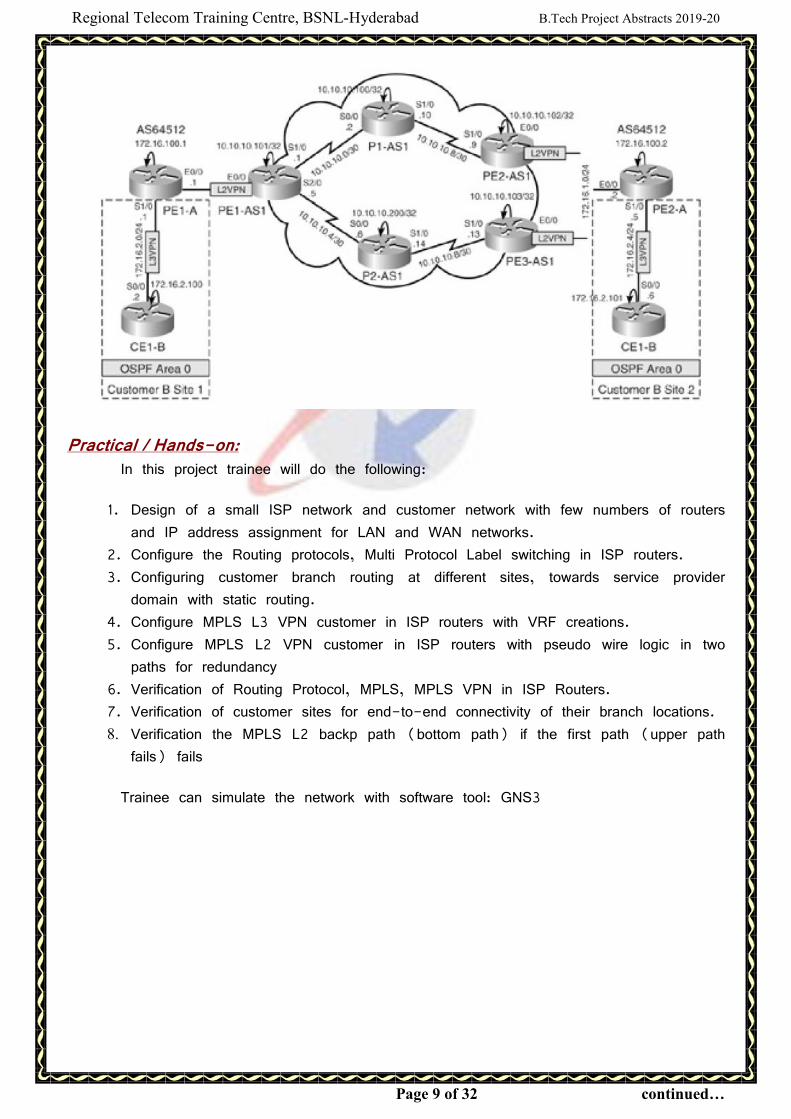
This project deals with configuration of MPLS L3 VPN over MPLS Layer 2 VPN
Topologies and Providing MPLS L2 VPN Redundancy as shown in the figure below.
Regional Telecom Training Centre, BSNL-Hyderabad B.Tech Project Abstracts 2019-20
Page 9 of 32 continued…
Practical / Hands-on: In this project trainee will do the following:
1. Design of a small ISP network and customer network with few numbers of routers
and IP address assignment for LAN and WAN networks.
2. Configure the Routing protocols, Multi Protocol Label switching in ISP routers.
3. Configuring customer branch routing at different sites, towards service provider
domain with static routing.
4. Configure MPLS L3 VPN customer in ISP routers with VRF creations.
5. Configure MPLS L2 VPN customer in ISP routers with pseudo wire logic in two
paths for redundancy
6. Verification of Routing Protocol, MPLS, MPLS VPN in ISP Routers.
7. Verification of customer sites for end-to-end connectivity of their branch locations.
8. Verification the MPLS L2 backp path (bottom path) if the first path (upper path
fails) fails
Trainee can simulate the network with software tool: GNS3
Regional Telecom Training Centre, BSNL-Hyderabad B.Tech Project Abstracts 2019-20
Page 10 of 32 continued…
ABSTRACT of Project No. 9
Implementing Layer 2 VPNs over Inter-AS Topologies
Using Layer 2 VPN Pseudo-Wire Switching with Ethernet
Importance of Network.
MPLS technology is being widely adopted by service providers worldwide to
implement VPNs to connect geographically separated customer sites. VPNs were originally
introduced to enable service providers to use common physical infrastructure to implement
emulated point-to-point links between customer sites. A customer network implemented with
any VPN technology would contain distinct regions under the customer's control called the
customer sites connected to each other via the service provider network.
In traditional router based networks, different sites belonging to the same customer
were connected to each other using dedicated point-to-point links. The cost of
implementation depended on the number of customer sites to be connected with these
dedicated links. A full mesh of connected sites would consequently imply an exponential
increase in the cost associated. Frame Relay and ATM were the first technologies widely
adopted to implement VPNs. These networks consisted of various devices, belonging to
either the customer or the service provider, that were components of the VPN solution.
Depending on the service provider's participation in customer routing, the VPN
implementations can be classified broadly into one of the following Overlay model, Peer-to-
peer model.
Overlay VPNs were initially implemented by the Service Provider by providing either
Layer 1 (physical layer) connectivity or a Layer 2 transport circuit between customer sites.
In the Layer 1 implementation, the Service Provider would provide physical layer connectivity
between customer sites, and the customer was responsible for all other layers. In the
Layer 2 implementation the Service Provider was responsible for transportation of Layer 2
frames (or cells) between customer sites, which was traditionally implemented using either
Frame Relay or ATM switches as Provider Edge devices.
The peer-to-peer model was developed to overcome the drawbacks of the Overlay
model and provide customers with optimal data transport via the Service Provider backbone.
Hence, the service provider would actively participate in customer routing. In the peer-to-
peer model, routing information is exchanged between the customer routers and the service
provider routers, and customer data is transported across the service provider's core,
optimally. Customer routing information is carried between routers in the provider network
and customer network
Project salient points Several requirements have resulted from the sudden growth in VPN deployments.
One such requirement is that VPNs need to reside on different service provider networks in
different geographic areas or extend across multiple service providers. To enable continuity
of VPN services across multiple service providers, the VPN information has to be mutually
redistributed. The Inter-AS or Inter-Provider VPN feature allows the VPN information to be
redistributed between adjacent MPLS VPN entities so that client sites dispersed across
multiple service provider backbones can communicate with each other.
Regional Telecom Training Centre, BSNL-Hyderabad B.Tech Project Abstracts 2019-20
Page 11 of 32 continued…
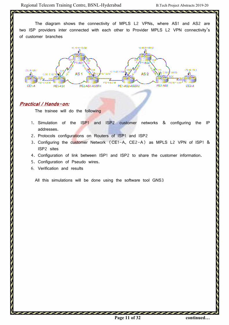
The diagram shows the connectivity of MPLS L2 VPNs, where AS1 and AS2 are
two ISP providers inter connected with each other to Provider MPLS L2 VPN connectivity’s
of customer branches
Practical / Hands-on: The trainee will do the following
1. Simulation of the ISP1 and ISP2 customer networks & configuring the IP
addresses.
2. Protocols configurations on Routers of ISP1 and ISP2
3. Configuring the customer Network (CE1-A, CE2-A) as MPLS L2 VPN of ISP1 &
ISP2 sites
4. Configuration of link between ISP1 and ISP2 to share the customer information.
5. Configuration of Pseudo wires.
6. Verification and results
All this simulations will be done using the software tool GNS3
Regional Telecom Training Centre, BSNL-Hyderabad B.Tech Project Abstracts 2019-20
Page 12 of 32 continued…
ABSTRACT of Project No. 10 Implementation and analysis of Fraud Management and Control Centre (FMCC)
in Real time Mobile network
Fraud in Telecom is an act committed to deprive the rightful revenue to the telecom service
provider, which affects the profit margin of the service provider. Besides revenue loss, it spoils the
reputation of a service provider and creates slack of confidence in the genuine subscribers. The
objective of Fraud Management and Control Centre (FMCC) is to detect, analyse and control
various frauds in a telecommunication network.
The FMCC system collects the CDRs from the various network elements like MSCs, IN,
SGSN, SMSC, GGSN etc. and collects the subscriber profile from the various Billing Systems. It
also collects live ISUP(BICC-ISUP,SIP) data from the various tapped SS7 signaling links and
constructs CDRs for cross checking with the Billing data. Frauds are manipulation of databases
(billing, charging, routing, etc.) through man-machine commands by authorised /unauthorised
persons.
Fraud detection techniques based on the analysis of messages on the CCS7 signaling links.
These links are monitored in a non-intrusive manner by connecting probes with high-impedance in
parallel to the CCS7 signalling links. FMCC builds Call Detail Records (CDR) in real time by
analysis of various call related parameters like calling number, called number etc. in CCS7
messages. Fraud detection is possible by analysis of usage profile, call patterns, calling trends
derived from CDRs and correlation of certain user defined parameters using software models. The
detection is achieved through various techniques: FMCC contains mainly three parts Remote site
equipment, central site equipment and Wide area network(WAN). On detection of a suspected
fraud, FMCC generates alerts to the manager. Based on the criteria defined by the manager,
alerts are converted into detailed cases, which include all relevant information needed to facilitate
investigation by manager, who can initiate manually initiated actions. Automatic actions by the
system are also possible
The FMCC can detect crossing of certain thresholds, which are user programmable.
Subscribers can be divided into groups like Home Group, Office Group, Business Group etc.
Thresholds can be set separately for any subscriber group. Subscription Frauds: Fraudster registers
for off-peak period) phone service, makes large number of calls (callselling) and runs away,
Large number of STD/ISD, calls will be made to the PRS and bills will not be paid but service
provider collects revenue share from network operator.
Handson / Practical: � Complete understanding of GSM/UMTS/LTE core networks working nature
� Different methods of network interrogation / Control Plane (Signalling) data analysis
� Different methods of Replication of sensitive data
� Offline/online data collection procedure
� Collection, conversion and loading various CDRs, profiles into database.
� Investigation and analysis of abnormal data
� Reports generation Through FMCC GUI.
� Reports creation and querying using sqlplus
Report: Final report preparation

Regional Telecom Training Centre, BSNL-Hyderabad B.Tech Project Abstracts 2019-20
Page 13 of 32 continued…
ABSTRACT of Project No. 11
Implementation of various Voice call features (CSFB, VoLTE, SRVCC, eSRVCC)
and Security features in 4G-LTE Packet core Network
Regardless of the pace of LTE networks deployment around the world the number
of users with 4G devices is intensively growing with lower costs - due to the gain of
production scale, and also by encouraging migration to 4G plans - offered by operators
who already have an available network, more and more people have access to new
services and benefits that this technology offers. However, as much as the current data
services are improved, and that progress in the area lead to the adoption of new
services, a basic necessity should still continue to exist at least for a while voice calls!
While making a voice call may seem simple, largely depends on the scenario where the
user is, and alternatives available for its completion. So it is necessary to understand well
what are the possibilities and the most important concepts of these key scenarios.
In the first generation of cellular networks, the communication through voice calls
was the main goal, and was based on a circuit switched topology or 'channels'.Over time,
the need for other services (data!) has emerged. Voice calls have come into existence
with these new services. As demand increasead, these new services were supported by a
new domain, the IP-based packet-switched (PS Packet Switched).
And in LTE (4G) system has another great change that CS domain has been
extinguished! LTE networks are based exclusively on the PS domain, and voice services
should be carried out in other ways. But regardless of network topologies, voice services
are still needed. With the continue growth of LTE networks, need to more the concepts,
alternatives and solutions for any user to make a voice call on an LTE network with
mobility support among legacy networks 2G/3G.
Circuit Switch Fall Back (CSFB): This is applicable to Operators where LTE is launched but VoLTE is still not
supported. Since LTE itself doesn’t support voice & its all IP to IP Network, It uses
legacy 3G / 2G network for providing voice services to user.
Voice over Long-Term Evolution (VoLTE) is a standard for high-speed wireless
communication for mobile phones and data terminals—including IoT devices and wearables.
It is based on the IP Multimedia Subsystem (IMS) network, with specific profiles for
control and media planes of voice service on LTE.This approach results in the voice
service (control and media planes) being delivered as data flows within the LTE data
bearer. This means that there is no dependency onthe legacy circuit-switched voice
network to be maintained. VoLTE has up to three times more voice and data capacity
than 3G UMTS and up to six times more than 2G GSM. Furthermore, it frees up
bandwidth because VoLTE’s packets headers are smaller than those of unoptimized
VoIP/LTE.
Regional Telecom Training Centre, BSNL-Hyderabad B.Tech Project Abstracts 2019-20
Page 14 of 32 continued…
Single Radio Voice Call Continuity (SRVCC): Basically, SRVCC is a call transfer method or handover, which is implemented in a
simplified and reliable manner used. When an LTE user has an active voice session in
IMS and is moving to areas, which have legacy 2G/3G coverage, and does not have
LTE coverage. For Example, The user moving to this Area will loose LTE coverage and
uses SRVCC for continuing voice VoLTE Call initiated earlier in LTE Coverage area.
eSRVCC is introduced to shorten the speech gap caused by SRVCC handovers.
LTE introduced a new set of cryptographic algorithms and a significantly different key
structure than that of GSM and UMTS. There are 3 sets of cryptographic algorithms for
both confidentiality and integrity termed EPS Encryption Algorithms (EEA) and EPS
Integrity Algorithms (EIA). While these new algorithms have been introduced in LTE,
network implementations commonly include older algorithms for backward compatibility for
legacy devices and cellular deployments. Many keys in LTE are 256-bits long, but in
some current implementations only the 128 least significant bits are used. The specification
has allowed for a system-wide upgrade from 128-bit to 256-bit keys.2 In LTE, the
control and user planes may use different algorithms and key sizes.
Practical/ Handson:
� Glance on the available GSM/UMTS/LTE core networks
� Observations on real time network.
� Analysys of Configutaion LTE network for voice calls using real time network
� Analysys of new security features LTE network using traces from real time
network
Report:
Final report preparation.
Regional Telecom Training Centre, BSNL-Hyderabad B.Tech Project Abstracts 2019-20
Page 15 of 32 continued…
ABSTRACT of Project No. 12 Design of Voice over WiFi system in VOIP network using CISCO 2811 Routers
with SIM less app based calling features
Existing system uses SIM card for utilising services by providing Authentication and
Authorisation of concerned subscriber. Based on the User profile the provider will provide different
services. Problem with existing system is user has to get the signal concerned service provider
and user unable make or receive call when he is out of coverage area .It requires physical SIM
slot is required in the mobile handset to utilize the mobile services. Disadvantage of Existing
System is Not suitable for IP environment, No convergence features, High CAPEX & OPEX and
Large Power, Cooling requirements.
Proposed system: PDSN Data Network: This network was basically designed for accessing remote files and
servers for defense people and universities but now a days nobody can think of living with data
network services. The basic and most popular application of data networks is Internet. VOIP is an
acronym for Voice Over Internet Protocol, or in more common terms phone service over the
Internet. Other terms commonly associated with VoIP are IP telephony, telephony Internet
telephony, telephony broadband telephony, elephony and broadband phone service. A VoIP phone
is necessary to connect to a VoIP service provider. As the term says VoIP tries to let go voice
(mainly human) through IP packets and, in definitive through Internet.
VoIP can use accelerating hardware to achieve this purpose and can also be used in a
Mobile and PC environment. The app can also be configured to be used on a computer by
downloading the SIP Client (App) that it will make use of any Internet Connection like
broadband, Wi-Fi, 3G/4G data network of any operator for placing calls. This means that one
can expect robust network connectivity in areas where cellular network is patchy but there is a
good Wi-Fi connection available. The service will enable consumers to make calls even in areas
with erratic network supply. Authentication is provided by using user id and password and
authorization provided based on the user id.
Cisco 2801, Cisco 2811, Cisco 2821, and Cisco 2851. The 2800 Series provides increased
security, voice, and overall performance, embedded service options, and dramatically increased slot
performance and density, as compared to older 2600 Series models Cisco Systems ®, Inc.
redefined best-in-class enterprise and small- to- midsize business routing with a new line of
integrated services routers that are optimized for the secure, wire-speed delivery of concurrent
data, voice, video, and wireless services. intelligently embed data, security, voice, and wireless
services into a single, resilient system for fast, scalable delivery of mission-critical business
applications. The unique integrated systems architecture of the Cisco 2800 Series delivers
maximum business agility and investment protection.
Practical/ Handson: � Preparation Project Design
� Configuration of VoIP server,
� Creation of nodes, Routing the calls, preparation of Call detailed records
Project requirements: � Front end: Smart phones, IPods, Laptops any WIFI enabled user devices.
Report: Final report preparation.
Regional Telecom Training Centre, BSNL-Hyderabad B.Tech Project Abstracts 2019-20
Page 16 of 32 continued…
ABSTRACT of Project No. 13
Design and implementation of ‘Connected Smart Campus’ on IoT platform
using Raspberry Pi by using Python & MySql technologies
A Smart campus intended connecting the worldwide educational resources to faculty
and students contributing in intellectual development. A smart campus should provide various
services to students, which makes the students campus life easier, comfortable and
attractive. These services are not just for academic life but also for socializing, moving
around, sharing events. Student’s thinking is impacted atleast in three directions: academic,
practical and social ways. Existing campuses could think of alternatives for positively
impacting the student in these three ways for a better socio-economic society tomorrow.
Campus to be provided with the facilities with broader scope to the student by
providing facility to listen, access and interact with the eminent faculty with broader
backgrounds .As student enters into the campus he has connected campus network using
wireless network using his smart phone with limited facilities. First he has to register
himself so that it is used show presence in the campus as also it used as attendance.
Concerned authority may check presence of users at any time in the campus. Users can
makes the audio and video calls to the to other users who are registered in the network
without any cost by using pre assigned numbers and they may have group discussion
using conference and chatting.
Campus requires IVRS system to update the day-to-day academic activities instead
of displaying in the notice board such as classes schedule, exam results and any important
events and announcements. Registered user should dial the pre-defined number to access
latest updates of campus related activities. Suitable menu based activity system required to
navigate it. Some times we require to inform important information like circulars like exam
schedule, social gathering and campus interviews. This can be implemented by making
outbound calls by dialing to the registered users by playing informative announcement by
using text to speech converters. Lecturers required to know their load such as classes on
that date and other works assigned to him.
As laptops, iPads and Smartphones have become more prevalent, there are
dramatic increases in WIFI usage. These features implemented by enabling the entire
campus with wifi access to get the services by installing access points at suitable locations
with wired back bone network. Backbone network connected to the VoIP server .All features
are initiated by using SIP protocol. One of the main advantage of WIFI having limited
coverage suitable for near field communication, unlicensed spectrum no need to purchase
the spectrum and we can have own frequency planning and greater bandwidth.
Regional Telecom Training Centre, BSNL-Hyderabad B.Tech Project Abstracts 2019-20
Page 17 of 32 continued…
In this project you are going use Raspberry Pi as server. The Raspberry Pi is a
series of small single-board computers developed in the United Kingdom by the Raspberry
Pi Foundation. This model became far more popular than anticipated, selling outside its
target market for uses such as robotics. Here we are using Raspberry PI as VoIP server,
which is economical and consumes less power compared to the traditional Desktop/Servers.
This project in also useful to make Private branch exchange PBX network for Small
Scale Industries, Apartments and College Campus
Project requirements:
� Front end: Smart phones, IPods, Laptops any WIFI enabled user devices
� Back end: WIFI hotspots, Raspberry Pi VoIP Server, SIP Protocol, My SQL
database, PHP.
� Services: IVRS, Outbound dialing, Push services, Conference, Voice and video
calls without the ISP
Practical/ Handson:
� Preparation Project Design
� Configuration of Raspberry Pi as VoIP server
� Creation of nodes • Routing the calls, preparation of Call detailed records
Observations:
In this is project student can able to develop monitoring and alerting system and
tests on Real time Network elements Router/Switches and its analysis.
Report:
Final report preparation.
Regional Telecom Training Centre, BSNL-Hyderabad B.Tech Project Abstracts 2019-20
Page 18 of 32 continued…
ABSTRACT of Project No. 14
Automated Monitoring of Physical environment in Telecom Networks using light
weight MQTT protocol implemented in Raspberry Pi with IoT approach
A recent huge interest in Machine-to-Machine communication is known as the
Internet of Things (IoT), to allow the possibility for autonomous devices to use Internet for
exchanging the data. Internet of Things (IoT) involves connecting physical objects to the
Internet to provide opportunities to build smart systems or applications. IoT paradigm
assumes many devices connected over conventional intent network. These devices usually
have restricted resources, so moving part of the service implementation to a cloud
infrastructure is a prominent solution.
This work presents design and execution of real time monitoring temperatures and
humidity in Telecom network Electronic soft switch rooms. The sensors used to
detect/identify unauthorized movement and any person/object being within a certain range
to critical network elements and to give an alert when ever any one approaching near by
hazardous elements like Battery and Power supply.
Maintenance staff have to manually look at it 24X7 and take the necessary steps
but by using this project we can minimize working efforts and improve accuracy, stability,
efficiency in unmanned timings also. In this project, sensors are used to sense the main
parameters of equipment such temperatures, humidity and motion. This sensed Raspberry Pi
reads data and this controller checks parameter limits which further send to the IoT web
server using IoT module. The information is in the hand to the Maintenance
personal/operator and they can make useful decisions before any catastrophic failure on
basis of that data/parameters. The humidity and temperature measurements are stored in a
Mysql database, which is installed on the web server. Over a dynamic web page the data
can be retrieved from almost every place in the world.
MQTT is a machine-to-machine (M2M)/"Internet of Things" connectivity protocol.
It was designed as an extremely lightweight publish/subscribe messaging transport. It is
useful for connections with remote locations where a small code footprint is required and/or
network bandwidth is at a premium
The Raspberry Pi is a series of small single-board computers developed in the
United Kingdom by the Raspberry Pi Foundation. This model became far more popular than
anticipated, selling outside its target market for uses such as robotics
Practical/ Handson:
� Preparation Project Design
� Configuration of Raspberry Pi, MySql,and Web server using MQTT protocol
� Interfacing with sensors
� Integration of IoT elements
Report:
Final report preparation.
Regional Telecom Training Centre, BSNL-Hyderabad B.Tech Project Abstracts 2019-20
Page 19 of 32 continued…
ABSTRACT of Project No. 15
Automated Monitoring of Physical environment in Telecom Networks
using Arduino Uno with IoT approach
A recent huge interest in Machine-to-Machine communication is known as the
Internet of Things (IoT), to allow the possibility for autonomous devices to use Internet for
exchanging the data. Internet of Things (IoT) involves connecting physical objects to the
internet to provide opportunities to build smart systems or applications. IoT paradigm
assumes many devices connected over conventional intent network. These devices usually
have restricted resources, so moving part of the service implementation to a cloud
infrastructure is a prominent solution.
This work presents design and execution of real time monitoring temperatures and
humidity in Telecom network Electronic soft switch rooms. The sensors used to
detect/identify unauthorized movement and any person/object being within a certain range
to critical network elements and to give an alert when ever any one approaching near by
hazardous elements like Battery and Power supply.
Maintenance staff have to manually look at it 24x7 and take the necessary steps
but by using this project we can minimize working efforts and improve accuracy, stability,
efficiency in unmanned timings also. In this project, sensors are used to sense the main
parameters of equipment such temperatures, humidity and motion. This sensed data is read
by Arduino Uno and this controller checks parameter limits which further send to the IoT
web server using IoT module. The information is in the hand to the Maintenance
personal/operator and they can make useful decisions before any catastrophic failure on
basis of that data/parameters. The humidity and temperature measurements are stored in a
MySql database, which is installed on the web server. Over a dynamic web page the data
can be retrieved from almost every place in the world.
Arduino UNO is a widely used open-source micro controller board based on the
Microchip ATmega328P micro controller and developed by Arduino.cc. The board is
equipped with sets of digital and analog input/output (I/O) pins that may be interfaced to
various expansion boards (shields) and other circuits.It can be powered by a USB cable
or by an external 9 volt battery, though it accepts voltages between 7 and 20 volts. It is
also similar to the Arduino Nano and Leonardo. The hardware reference design is
distributed under a Creative Commons Attribution Share-Alike 2.5 license and is available
on the Arduino website
Practical/ Handson:
� Preparation Project Design
� Interfacing with sensors &Actuators
� Integration of Arduino, ESP01 and sensors and actuators
Report:
Final report preparation.
Regional Telecom Training Centre, BSNL-Hyderabad B.Tech Project Abstracts 2019-20
Page 20 of 32 continued…
ABSTRACT of Project No. 16
Automated Monitoring of Physical environment in Telecom Networks using
NodeMCU with IoT approach by light weight MQTT protocol
using Micro Python programing A recent huge interest in Machine-to-Machine communication is known as the
Internet of Things (IoT), to allow the possibility for autonomous devices to use Internet for
exchanging the data. Internet of Things (IoT) involves connecting physical objects to the
Internet to provide opportunities to build smart systems or applications. IoT paradigm
assumes many devices connected over conventional intent network. These devices usually
have restricted resources, so moving part of the service implementation to a cloud
infrastructure is a prominent solution.
This work presents design and execution of real time monitoring temperatures and
humidity in Telecom network Electronic soft switch rooms. The sensors used to
detect/identify unauthorized movement and any person/object being within a certain range
to critical network elements and to give an alert when ever any one approaching near by
hazardous elements like Battery and Power supply.
Maintenance staff have to manually look at it 24X7 and take the necessary steps
but by using this project we can minimize working efforts and improve accuracy, stability,
efficiency in unmanned timings also. In this project, sensors are used to sense the main
parameters of equipment such temperatures, humidity and motion. This sensed data is read
by NodeMCU and this controller checks parameter limits which further send to the IoT web
server using IoT module. The information is in the hand to the Maintenance
personal/operator and they can make useful decisions before any catastrophic failure on
basis of that data/parameters. The humidity and temperature measurements are stored in a
Mysql database, which is installed on the web server. Over a dynamic web page the data
can be retrieved from almost every place in the world.
NodeMCU is an open source IoT platform It includes firmware which runs on the
ESP8266 Wi-Fi SoC from Espressif Systems, and hardware which is based on the ESP-
12 module.[ The term "NodeMCU" by default refers to the firmware rather than the
development kits. The firmware uses the Lua scripting language. It is based on the eLua
project, and built on the Espress if Non-OS SDK for ESP8266. It supports other
Programming languages/scripts such as Micro Python and Arduino(C++)
MicroPython is a lean and efficient implementation of the Python 3 programming
language that includes a small subset of the Python standard library and is optimised to
run on micro controllers and in constrained environments
Practical/ Handson: � Configuration of Raspberry Pi, MySql,and Web server
� Programming with Micro Python and Arduino(C++)
� Interfacing with sensors
� Integration of IoT elements
Report: Final report preparation.
Regional Telecom Training Centre, BSNL-Hyderabad B.Tech Project Abstracts 2019-20
Page 21 of 32 continued…
ABSTRACT of Project No. 17
Mobile Cellular Network based Smart Home with Google Assistant by
usingNode MCU with IOT approach Home automation evolution starts with some basic ideas. It minimizes the human
efforts and it can be deployed in a lot of fields like military, surveillance application is
developed in the modern world. Now a day’s Home automation is developed by using
Wireless technology. Wireless technology in Home automation starts with Bluetooth, WI-FI,
and Zigbee Communication. Blynk is a Popular App used in this Project it has a lot of
Features like buttons, gauges, Sliders and Plotting Features also. By using Wi-Fi
technology we can connect a greater number of Home automation to control it very useful
for surveillance application.
The main objective of this project is to develop a home automation system using
an Node MCU board with Internet being remotely controlled by any Android OS smart
phone. As technology is advancing so houses are also getting smarter. Modern houses are
gradually shifting from conventional switches to centralized control system, involving remote
controlled switches. Presently, conventional wall switches located in different parts of the
house makes it difficult for the user to go near them to operate. Even more it becomes
more difficult for the elderly or physically handicapped people to do so. Remote controlled
home automation system provides a most modern solution with smart phones.
In order to achieve this, a relay module is interfaced to the Node MCU board at
the receiver end while on the transmitter end, a GUI application on the cell phone sends
ON/OFF commands to the receiver where loads are connected. By touching the specified
location on the GUI, the loads can be turned ON/OFF remotely through this technology.
The loads are operated by IoT board through Relay Module
GSM module is used to send / receive messages and make / receive calls as
a mobile phone a SIM card from network source. The module uses the SIMComm function.
It is be able to communicate easily with the module through AT commands. GSM library
contains several methods of communication with the module. The GSM modem can work
with any GSM network operator SIM card like a mobile phone with its own unique
telephone number. The advantage of this modem is the RS232 interface can be used to
communicate and develop integrated applications. Control applications such as SMS, data
transmission, remote monitoring and recording can be easily developed with this. GPRS
mode can also connect to an FTP server and files for data download this GSM modem
registration is a GSM Modem SIM900A Quad-band GSM modem and run very flexible for
easy integration with direct applications. It supports functions like voice, SMS, data / FAX,
GPRS and integrated TCP / IP stack. Up to a mobile network can be connected; the
module requires a SIM card provided by a network provider.
Practical/ Handson: � Preparation Project Design
� Configuration of Node MCU
� Interfacing with GSM SIM 900 module
� Interfacing with sensors
Report: Final report preparation.

Regional Telecom Training Centre, BSNL-Hyderabad B.Tech Project Abstracts 2019-20
Page 22 of 32 continued…
Introduction for Optical Fiber Communication /Transmission Projects.
(Common for projects No. 3 to No.6)
In telecommunications Optical fibers plays an important role because it carries the
data from transmitter to the receiver very effectively than other wired networks.
Optical fibers can be used to transmit light and thus information over long distances at
higher bandwidths. In most of the optical networks, silica fibers are used. The capacity of
fibers for data transmission is huge: a single silica fiber can carry lacks of telephone
channels. The cost per transported channel can be extremely low. The losses for light
propagating in fibers are amazingly small: ≈0.25 dB/km for modern single-mode silica
fibers, so that many tens of kilometers can be bridged without regenerating /amplifying the
signals.
Today, optical fibers are not only used in telecommunication links but also used
Local area networks (LAN), Gigabit Ethernet, SDH/SONET, ATM, ESCON, Fiber Channel
and CATV. Currently the optical fiber used in to access networks. The “last mile” to
business and home subscribers through FTTH services like IPTV/RF Video, VOIP, High
Speed Internet and future advanced services with High quality of service, high reliability,
flexibility, all in IP, future proof and using the network resources effectively.
To develop multimedia telecommunication networks as an infrastructure, it is
necessary to install the highly reliable optical fiber cable network architecture along with
traditional SDH, Next Generation SDH, and Dense Wave Length Division Multiplexing
(DWDM) Systems. Wavelength Division Multiplexing (WDM) is an effective technique for
utilizing the large bandwidth of an optical fiber.
The thrust of this project is on OFC/SDH/DWDM technology and it will create
awareness to the service provider network architecture, principles of OFC, different SDH
systems namely STM-4/16 of vendor name Tejas. In this project the real time environment
with hands on exposure to readily install and working OFC/STM-4/STM-16 systems along
with necessary Testing Instruments is covered. This project gives the complete details about
the theoretical and practical background to various OFC/SDH systems.
If desired to build awareness in telecom and enhance career prospects in the
Telecom industry especially in transmission specialization, this is the best-suited project.
Regional Telecom Training Centre, BSNL-Hyderabad B.Tech Project Abstracts 2019-20
Page 23 of 32 continued…
ABSTRACT of Project No. 18
Overview on Fibre Network and FTTH
Objective: This project involves the study of Optical Fiber characteristics, Splicing of OF cable,
Termination of OF Cable in TJB and Installation of FDF and extending of Fibers to
Systems and installation of 1:8 Spliiet for extending the Fiber to the Home connectivity for
the Splitter to the ONT and Various OF Measurements
Hardware:
1. 24 F Cable 2. Joint closure 3. 1:8 Splitter 4. Splicing Machine 5. Optical Power meter 6. OTDR 7. TJB 8. FDF 9. Various Patch cards and Pigtails.
Short Glance Of Project 1. Awarenes of OF cable structure 2. Types of OF cables and their applications in the field 3. Splicing of OF cable 4. Extending the connectivity to Splitter from OLT 5. Extending the connectivity to ONT/ ONU 6. Measurement of Optical Power 7. OF cable characteristics verification through OTDR
Final Review
Participant will be able to build a Fiber Optic network and get good acquaintance
with Fiber to the Home technologies.

Regional Telecom Training Centre, BSNL-Hyderabad B.Tech Project Abstracts 2019-20
Page 24 of 32 continued…
ABSTRACT of Project No. 19
Overview of Optical Fiber Cable Network maintenance with the help of
Instruments like Power Meter and OTDR
Objective:
This project involves the study of Optical Fiber History, Optical Fiber cable
characteristics, Different types of Splicing techniques, Splicing of OF cable, Termination of
OF Cable in TJB and Installation of FDF, extending of Fibers to Systems, study cable
diagrams, study of OTDR and power meter
Hardware:
1. 24 F Cable
2. Joint closure kit
3. Tools required for Splicing preperation
4. Splicing Machine
5. Optical Power meter
6. OTDR
7. TJB
8. FDF
9. Various Patch cards and Pigtails.
10. Various connectors.
Short Glance Of Project 1. Awareness of OF cable structure 2. Types of OF cables and their applications in the field 3. Splicing of OF cable 4. Termination of OF cable at TJB and FDF 5. Measurement of Optical Power 6. OF cable characteristics verification through OTDR
Final Review
Participant will be able to build a Fiber Optic network and get good acquaintance
with power meter and OTDR
Regional Telecom Training Centre, BSNL-Hyderabad B.Tech Project Abstracts 2019-20
Page 25 of 32 continued…
ABSTRACT of Project No. 20
Design and Implementation of High Bandwidth to Corporate Network between
Two Next Generation SDH (STM-4) Nodes
Objective: Synchronous Digital Hierarchy (SDH) is a standard for telecommunications transport
formulated by the International Telecommunication Union (ITU). It is deployed at all levels
of the network infrastructure including the access network and the long-distance trunk
network. It is based on synchronous multiplexed signal onto a light stream transmitted over
Optical fiber. SDH improves the configuration flexibility and bandwidth availability over the
conventional Telecom transmission system.
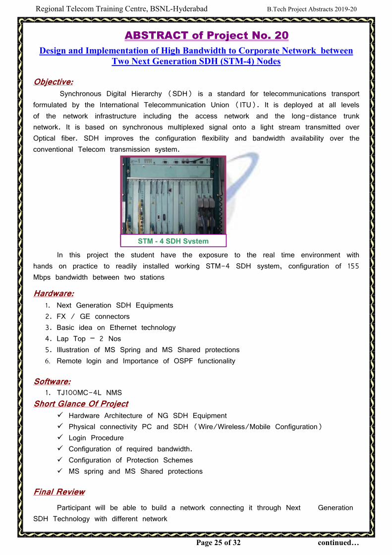
In this project the student have the exposure to the real time environment with
hands on practice to readily installed working STM-4 SDH system, configuration of 155
Mbps bandwidth between two stations
Hardware:
1. Next Generation SDH Equipments
2. FX / GE connectors
3. Basic idea on Ethernet technology
4. Lap Top – 2 Nos
5. Illustration of MS Spring and MS Shared protections
6. Remote login and Importance of OSPF functionality
Software: 1. TJ100MC-4L NMS
Short Glance Of Project � Hardware Architecture of NG SDH Equipment
� Physical connectivity PC and SDH (Wire/Wireless/Mobile Configuration)
� Login Procedure
� Configuration of required bandwidth.
� Configuration of Protection Schemes
� MS spring and MS Shared protections
Final Review
Participant will be able to build a network connecting it through Next Generation
SDH Technology with different network
STM - 4 SDH System
Regional Telecom Training Centre, BSNL-Hyderabad B.Tech Project Abstracts 2019-20
Page 26 of 32 continued…
ABSTRACT of Project No. 21
Design & implementation of 2 Mbps bandwidth to Corporate Sector by using SDH
Technology in with Protection
Objective: Synchronous Digital Hierarchy (SDH) is a standard for telecommunications transport
formulated by the International Telecommunication Union (ITU). It is deployed at all levels
of the network infrastructure including the access network and the long-distance trunk
network. It is based on synchronous multiplexed signal onto a light stream transmitted over
Optical fiber. SDH improves the configuration flexibility and bandwidth availability over the
conventional Telecom transmission system.
In this project the student have the exposure to the real time environment with
hands on practice to readily installed working STM-4 SDH system, configuration of
2 Mbps, 10 Mbps between two stations along with protection and Testing with Digital
Transmission Analyze.
Hardware:
1. Next Generation SDH Equipments
2. PC
3. PCM Cable
4. DDF
5. CAT-5/6 RJ 45 Cable
6. Laptops- 2 Nos for pinging
Software: 1. TJ100MC-4L NMS
Short Glance Of Project
� PCM Basic prinicples, Introduction of SDH , NGSDH
� Hardware Architecture of SDH & NG SDH Equipment
� Physical Wiring of PCM Cable
� Physical connectivity PC and SDH (Wire/Wireless/Mobile Configuration)
� Login Procedure
� Configuration of 2Mbps bandwidth
� Configuration of 10Mbps bandwidth
� Configuration of Protection Schemes
� Significance of Virtual concatenation and Link capacity adjustment scheme
Final Review
Participant will be able to build a network with Optical fibre cable, connecting nodes
within Ring and able to create different bandwidths between 2 NG SDH Transmission
systems

Regional Telecom Training Centre, BSNL-Hyderabad B.Tech Project Abstracts 2019-20
Page 27 of 32 continued…
ABSTRACT of Project No. 22
Integrated Network platform for Next Generation Telecom network (NGN)
Introduction: India's telecommunication network is the second largest in the world based on the
total number of telephone users (both fixed and mobile phone). The concept of Next
Generation Network (NGN) was conceived since 2005 onwards as an integrated solution
to combine the quality and features of the PSTN with the low cost and routing flexibility of
the Internet to provide a single infrastructure for the future public network. This carrier
grade Internet solution calls for the creation of a consolidated, packet transport and
switching infrastructure and the development of a flexible, open, software switch
(softswitch) to handle voice telephony as well as multimedia services. Almost all the
telecom equipment manufacturers as well as some Internet equipment vendors immediately
subscribed to this vision and joined the race to create convergent products for the NGN
market. NGN project is being implemented by many service providers in INDIA and also in
western countries. It is being implementing in a phased manner.
Existing System: Presently telecommunications system employs one of the three types of the following
networks based on the end-user requirements. Those are
1. PSTN: Public Switch Telephone Network was basically developed and engineered for giving
voice connectivity to the wire line subscribers. The network consists of Local
exchange/RSU as a part of Access Network and TAXs as a part of core Network.
Already huge amount of money has been invested in PSTN setup. Because of tough
competition from Mobile & Voice over IP, it is becoming white elephant day by day for
the operators. Another fact about PSTN is that most of its equipments are going to
exhaust their lives in coming years.
2. PLMN:(Public Land Mobile Network): PLMN has been developed to provide voice services
for wireless subscribers. PLMN includes BTS/BSC as access network and MSC as a core
Network.
3. Data Network: This network was basically designed for accessing remote files and servers
for defense people and universities but now a days nobody can think of living with data
network services. The basic and most popular application of data networks
is Internet. Other applications include E-commerce, online banking, online gaming,
E-shopping, IPTV Video on demand and many more. Data network is an assembly of
routers, which are responsible for forwarding information from one end to other.
Disadvantage of Existing System: 1. Slow to develop new technologies
2. Not compatible for IP platform
3. No convergence features
4. High CAPEX & OPEX due to maintenance of different networks for different services.
5. Large Power, Cooling requirements.
Regional Telecom Training Centre, BSNL-Hyderabad B.Tech Project Abstracts 2019-20
Page 28 of 32 continued…
Proposed System: Proposed system is a single converged network that supports all telecom
requirements like voice, data, mobility, video etc. and works on packet switching technology
and IP compatible. This emerging network for Telecommunications is called as Next
Generation Network (NGN), which is the future telecom network
NGN Definition: A Next Generation Network (NGN) is a packet-based network able to provide
Telecommunication Services to users and able to make use of multiple broadband, QoS-
enabled transport technologies and in which service-related functions are independent of the
underlying transport-related technologies. It enables unfettered access for users to networks
and to competing service providers and services of their choice. It supports generalized
mobility, which will allow consistent and ubiquitous provision of services to users.
[ITU-T Recommendation Y.2001-General overview of NGN] NGN Architecture:
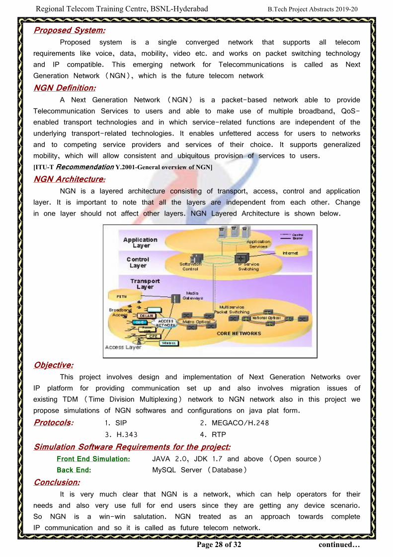
NGN is a layered architecture consisting of transport, access, control and application
layer. It is important to note that all the layers are independent from each other. Change
in one layer should not affect other layers. NGN Layered Architecture is shown below.
Objective:
This project involves design and implementation of Next Generation Networks over
IP platform for providing communication set up and also involves migration issues of
existing TDM (Time Division Multiplexing) network to NGN network also in this project we
propose simulations of NGN softwares and configurations on java plat form.
Protocols: 1. SIP 2. MEGACO/H.248
3. H.343 4. RTP
Simulation Software Requirements for the project: Front End Simulation: JAVA 2.0, JDK 1.7 and above (Open source)
Back End: MySQL Server (Database)
Conclusion: It is very much clear that NGN is a network, which can help operators for their
needs and also very use full for end users since they are getting any device scenario.
So NGN is a win-win salutation. NGN treated as an approach towards complete
IP communication and so it is called as future telecom network.
Regional Telecom Training Centre, BSNL-Hyderabad B.Tech Project Abstracts 2019-20
Page 29 of 32 continued…
ABSTRACT of Project No. 23
Implementation of Mobile Number Portability in PSTN switch
Introduction “Mobile Number Portability"(MNP) means the facility which allows a subscriber of
a mobile telephone service to retain his mobile telephone number when he moves from one
mobile telephone service provider to another, irrespective of the mobile technology or from
one mobile technology to another of the same mobile telephone service provider, within
such limits as may be permitted by the licensor”
� Portability of Mobile Numbers between all GSM and CDMA operators within the same
Service Area.
� A Mobile subscriber can change his/her operator within the same Service Area without
changing his/her number.
� No Portability beyond Service Area.
� Portability between GSM and CDMA network of same operator in same service area
possible.
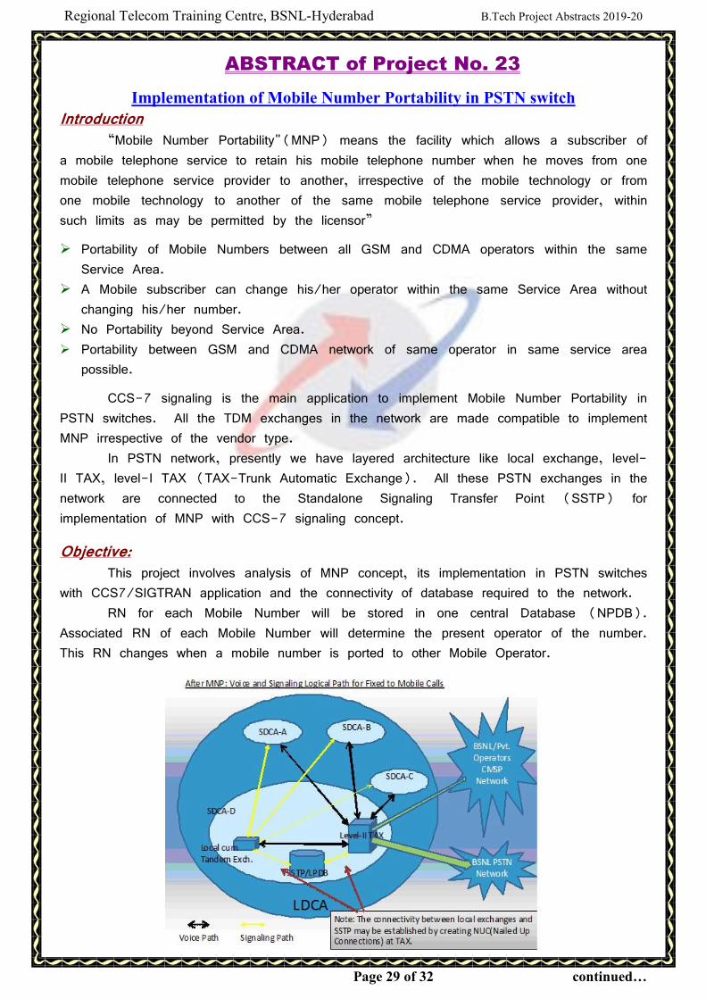
CCS-7 signaling is the main application to implement Mobile Number Portability in
PSTN switches. All the TDM exchanges in the network are made compatible to implement
MNP irrespective of the vendor type.
In PSTN network, presently we have layered architecture like local exchange, level-
II TAX, level-I TAX (TAX-Trunk Automatic Exchange). All these PSTN exchanges in the
network are connected to the Standalone Signaling Transfer Point (SSTP) for
implementation of MNP with CCS-7 signaling concept.
Objective: This project involves analysis of MNP concept, its implementation in PSTN switches
with CCS7/SIGTRAN application and the connectivity of database required to the network.
RN for each Mobile Number will be stored in one central Database (NPDB).
Associated RN of each Mobile Number will determine the present operator of the number.
This RN changes when a mobile number is ported to other Mobile Operator.

Regional Telecom Training Centre, BSNL-Hyderabad B.Tech Project Abstracts 2019-20
Page 30 of 32 continued…
“IAM Relay” method is used for implementing MNP in BSNL. In IAM Relay
method SSTP must intercept all IAMs for fixed to mobile calls originating from local
exchanges and prefix the RN number with B party number in the IAM before sending the
same to Level-I/II Taxs/Tandems. This RN+B number information used by Level I/II
Taxs/Tandems to route the call to correct service provider. Necessary creation of routing
and charging information is required to be done at Level I/II Taxs. This method requires
connecting all the local exchanges with SSTP.
Conclusion: In this project we analyze the concept of IAM Relay method in SSTP, and concept
of CCS7 signaling implementation in all the TDM local/Tax exchanges in the network by
connecting it to SSTP and we will establish MNP on CCS-7 platform is useful to both
end-users as well as network provides.
Regional Telecom Training Centre, BSNL-Hyderabad B.Tech Project Abstracts 2019-20
Page 31 of 32 continued…
ABSTRACT of Project No. 24
Implementation of efficient signaling scheme i.e Session Initiation Protocol
than traditional TDM based SS7 for Telecom networks
Introduction Telecom Signaling refers to exchange of information between call components
required to provide and maintain service. Efficiency of Telecom networks i.e voice or data
depends of proper signaling schemes used and ultimately should meet the emergent
customer requirements. Signaling System No. 7(SS7) is a set of telephony signaling
protocols, which are being used to set up most of the world's public switched telephone
network (PSTN) telephone calls. The main purpose is to set up and tear down legacy
voice calls. Other uses include number translation, local number portability, prepaid billing
mechanisms, short message service(SMS), and a variety of other mass-market services.
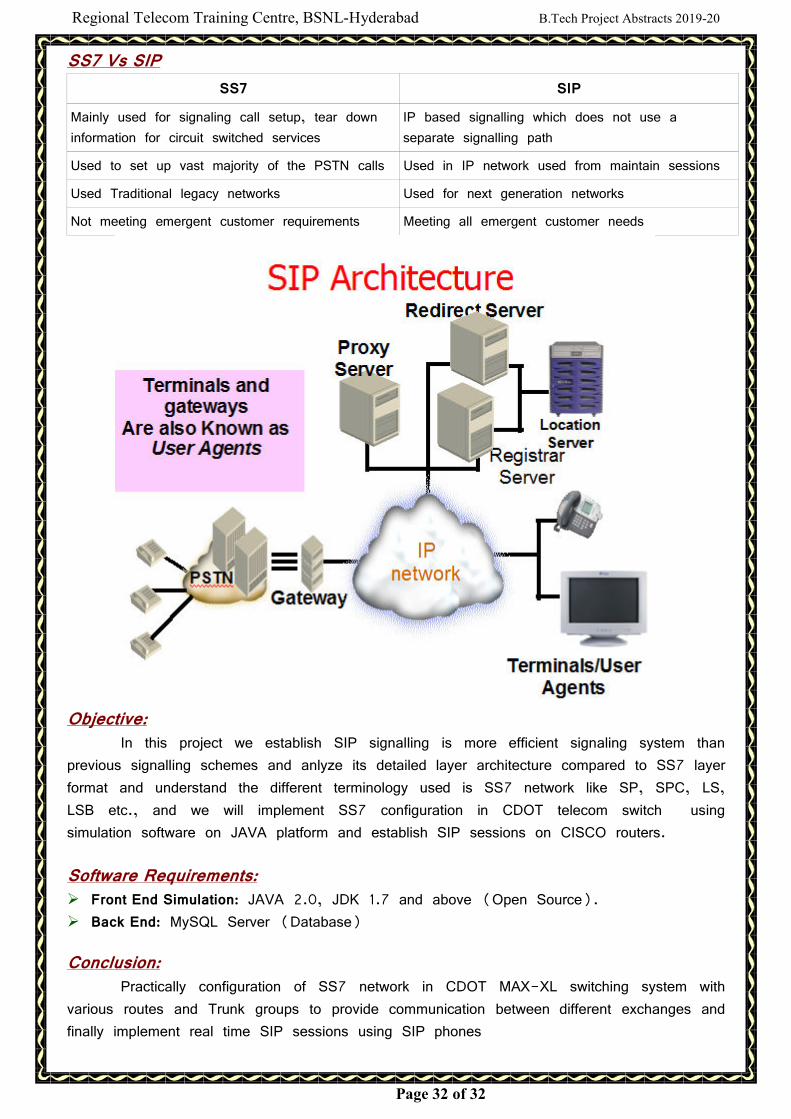
Session Initiation protocol (SIP) is an efficient signalling protocol works on packet
based environment to deliver the emergent customer needs I.e initiating, maintaining and
terminating real-time sessions that include voice, video VOIP applications.
It is usually referenced as Signalling System No. 7 or Signalling System #7, or
simply abbreviated to SS7. In North America it is often referred to as CCSS7, an
abbreviation for Common Channel Signalling System 7. In some European countries,
specifically the United Kingdom, it is sometimes called C7 (CCITT number 7) and is also
known as number 7 and CCIS7 (Common Channel Interoffice Signaling 7). In Germany it
is often called N7 (Signalisierungssystem Number 7).
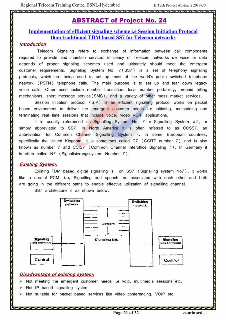
Existing System: Existing TDM based digital signalling is on SS7 (Signalling system No7), it works
like a normal PCM. i.e, Signalling and speech are associated with each other and both
are going in the different paths to enable effective utilization of signalling channel.
SS7 architecture is as shown below.
Disadvantage of existing system: � Not meeting the emergent customer needs I.e voip, multimedia sessions etc.
� Not IP based signalling system
� Not suitable for packet based services like video conferencing, VOIP etc.
Regional Telecom Training Centre, BSNL-Hyderabad B.Tech Project Abstracts 2019-20
Page 32 of 32 continued…
SS7 Vs SIP
SS7 SIP
Mainly used for signaling call setup, tear down
information for circuit switched services
IP based signalling which does not use a
separate signalling path
Used to set up vast majority of the PSTN calls Used in IP network used from maintain sessions
Used Traditional legacy networks Used for next generation networks
Not meeting emergent customer requirements Meeting all emergent customer needs
Objective: In this project we establish SIP signalling is more efficient signaling system than
previous signalling schemes and anlyze its detailed layer architecture compared to SS7 layer
format and understand the different terminology used is SS7 network like SP, SPC, LS,
LSB etc., and we will implement SS7 configuration in CDOT telecom switch using
simulation software on JAVA platform and establish SIP sessions on CISCO routers.
Software Requirements: � Front End Simulation: JAVA 2.0, JDK 1.7 and above (Open Source).
� Back End: MySQL Server (Database)
Conclusion: Practically configuration of SS7 network in CDOT MAX-XL switching system with
various routes and Trunk groups to provide communication between different exchanges and
finally implement real time SIP sessions using SIP phones