Embed Size (px)
Citation preview
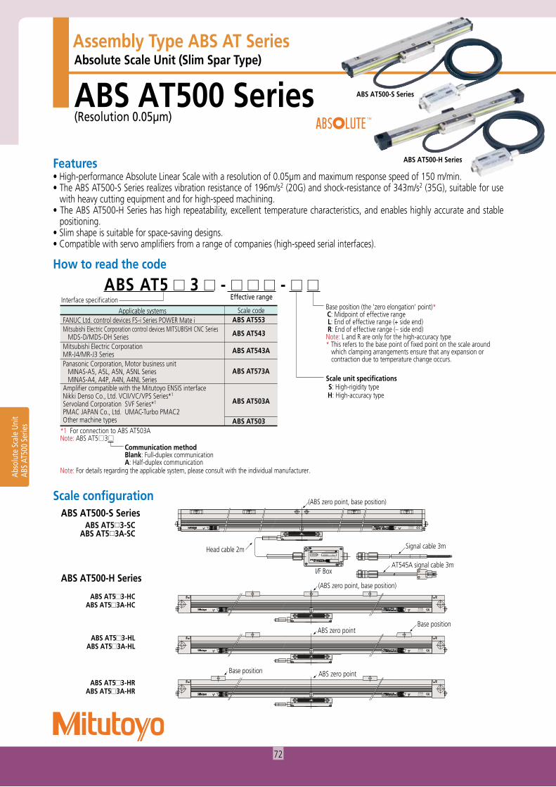
Absolute Scale Unit (Slim Spar Type)
ABS AT500 Series(Resolution 0.05μm)
Assembly Type ABS AT Series
ABS AT5 3 - - Interface specification Effective range
Base position (the 'zero elongation' point)* C: Midpoint of effective range L: End of effective range (+ side end) R: End of effective range (– side end)Note: L and R are only for the high-accuracy type* This refers to the base point of fixed point on the scale around
which clamping arrangements ensure that any expansion or contraction due to temperature change occurs.
Scale unit specifications S: High-rigidity type H: High-accuracy type
Applicable systemsFANUC Ltd. control devices FS-i Series POWER Mate i Mitsubishi Electric Corporation control devices MITSUBISHI CNC Series MDS-D/MDS-DH SeriesMitsubishi Electric Corporation MR-J4/MR-J3 SeriesPanasonic Corporation, Motor business unit MINAS-A5, A5L, A5N, A5NL Series MINAS-A4, A4P, A4N, A4NL SeriesAmplifier compatible with the Mitutoyo ENSIS interfaceNikki Denso Co., Ltd. VCII/VC/VPS Series*1
Servoland Corporation SVF Series*1
PMAC JAPAN Co., Ltd. UMAC-Turbo PMAC2Other machine types
Note: ABS AT5 3
Note: For details regarding the applicable system, please consult with the individual manufacturer.
*1 For connection to ABS AT503A
Communication methodBlank: Full-duplex communicationA: Half-duplex communication
Scale code ABS AT553
ABS AT543
ABS AT543A
ABS AT573A
ABS AT503A
ABS AT503
MADE IN JAPAN
AT500
SERIALNo.1234567ALARM
ModelAT���
Mitutoyo Corporation
MADE IN JAPAN
AT500
MADE IN JAPAN
AT500
AT500MADE IN JAPAN
(ABS zero point, base position)
I/F Box
(ABS zero point, base position)
ABS zero point
ABS zero point
Base position
Base position
Signal cable 3mHead cable 2m
AT545A signal cable 3m
Abso
lute
Sca
le U
nit
ABS
AT50
0 Se
ries
ABS AT500-S Series
ABS AT500-H Series
• High-performance Absolute Linear Scale with a resolution of 0.05μm and maximum response speed of 150 m/min.• The ABS AT500-S Series realizes vibration resistance of 196m/s2 (20G) and shock-resistance of 343m/s2 (35G), suitable for use
with heavy cutting equipment and for high-speed machining.• The ABS AT500-H Series has high repeatability, excellent temperature characteristics, and enables highly accurate and stable
positioning.• Slim shape is suitable for space-saving designs.• Compatible with servo amplifiers from a range of companies (high-speed serial interfaces).
Features
How to read the code
ABS AT500-S Series
ABS AT500-H Series
ABS AT5 3-SCABS AT5 3A-SC
ABS AT5 3-HCABS AT5 3A-HC
ABS AT5 3-HLABS AT5 3A-HL
ABS AT5 3-HRABS AT5 3A-HR
Scale configuration
72
Feedback cable
SERIALNo.1234567ALARM
ModelAT∃∃∃
Mitutoyo CorporationMADE IN JAPAN
Scale unit
Head cable
I/F Box Signal cable
(Grounding conductor)
Mitsubishi Electric CorporationMR-J4/MR-J3
Connector AConnector B
SERIALNo.1234567ALARM
ModelAT∃∃∃
Mitutoyo CorporationMADE IN JAPAN
Scale unit
Head cable
I/F Box Signal cable
Connector C Feedback cable
Connector A
(Control device)
(Grounding conductor)
Connector B
SERIALNo.1234567ALARM
ModelAT���
Mitutoyo Corporation
MADE IN JAPAN
AT500
Scale unit
Head cable
I/F BoxSignal cable
(Grounding conductor)
(Control device)
Connector A
Notes1. Connector A is to be prepared by the user.2. Connector A and the grounding conductor are to be connected by the user.3. In the above configuration, the maximum cable length is 10m for the head cable and 10m for the signal cable (total 20m). (Specifications other than the standard cable length are special order.)
[ABS AT543A]
Feedback cable
SERIALNo.1234567ALARM
ModelAT∃∃∃
Mitutoyo CorporationMADE IN JAPAN
Scale unit
Head cable
I/F Box Signal cable
(Grounding conductor)
Mitsubishi Electric CorporationMR-J4/MR-J3
Connector AConnector B
SERIALNo.1234567ALARM
ModelAT∃∃∃
Mitutoyo CorporationMADE IN JAPAN
Scale unit
Head cable
I/F Box Signal cable
Connector C Feedback cable
Connector A
(Control device)
(Grounding conductor)
Connector B
Abso
lute
Sca
le U
nit
ABS
AT50
0 Se
ries
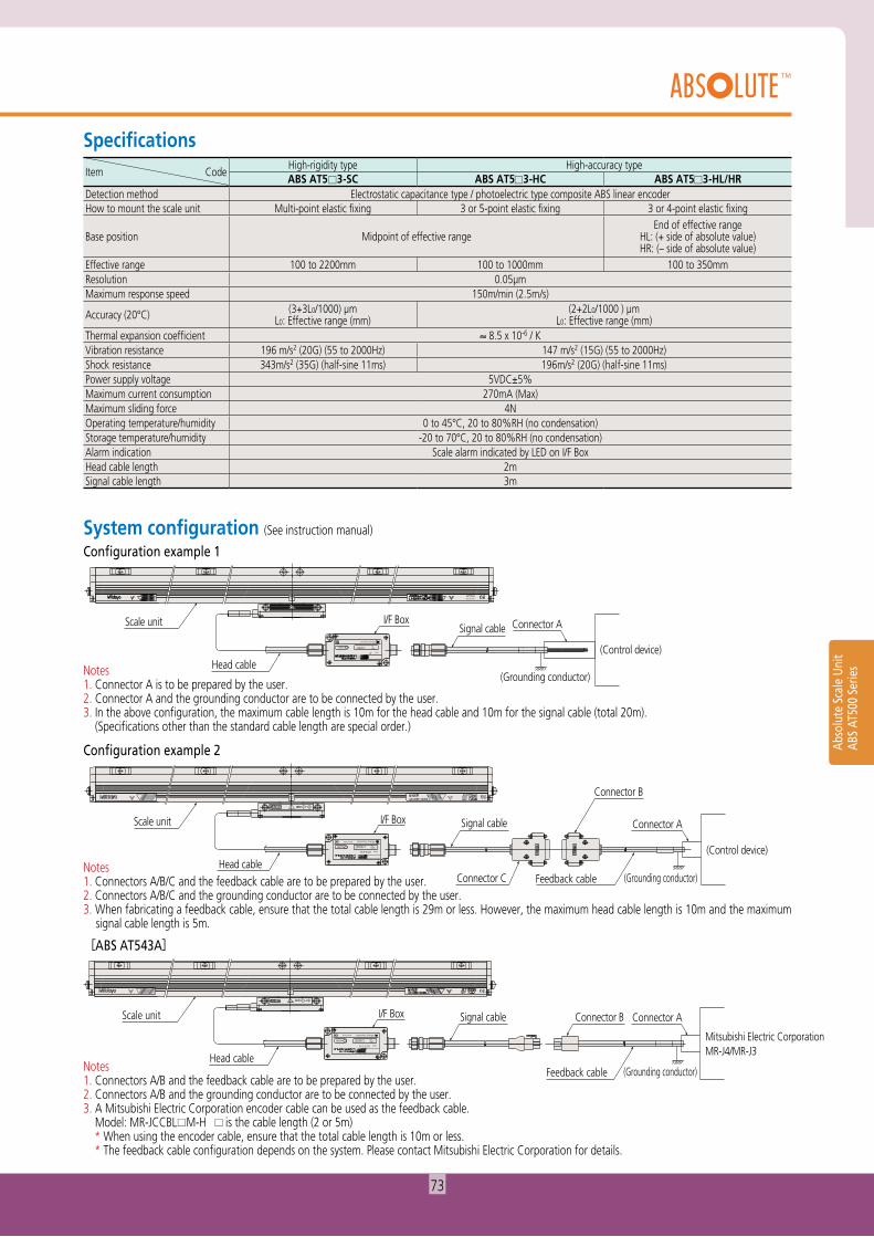
SpecificationsCodeItem
High-rigidity type High-accuracy typeABS AT5 3-SC ABS AT5 3-HC ABS AT5 3-HL/HR
Detection method Electrostatic capacitance type / photoelectric type composite ABS linear encoderHow to mount the scale unit Multi-point elastic fixing 3 or 5-point elastic fixing 3 or 4-point elastic fixing
Base position Midpoint of effective rangeEnd of effective range
HL: (+ side of absolute value)HR: (– side of absolute value)
Effective range 100 to 2200mm 100 to 1000mm 100 to 350mmResolution 0.05μmMaximum response speed 150m/min (2.5m/s)
Accuracy (20°C) (3+3L0/1000) μmL0: Effective range (mm)
(2+2L0/1000 ) μmL0: Effective range (mm)
Thermal expansion coefficient ≈ 8.5 x 10⁻⁶ / KVibration resistance 196 m/s2 (20G) (55 to 2000Hz) 147 m/s2 (15G) (55 to 2000Hz)Shock resistance 343m/s2 (35G) (half-sine 11ms) 196m/s2 (20G) (half-sine 11ms)Power supply voltage 5VDC±5%Maximum current consumption 270mA (Max)Maximum sliding force 4NOperating temperature/humidity 0 to 45°C, 20 to 80%RH (no condensation)Storage temperature/humidity -20 to 70°C, 20 to 80%RH (no condensation)Alarm indication Scale alarm indicated by LED on I/F BoxHead cable length 2mSignal cable length 3m
Configuration example 1
Notes1. Connectors A/B/C and the feedback cable are to be prepared by the user.2. Connectors A/B/C and the grounding conductor are to be connected by the user.3. When fabricating a feedback cable, ensure that the total cable length is 29m or less. However, the maximum head cable length is 10m and the maximum
signal cable length is 5m.
Configuration example 2
Notes1. Connectors A/B and the feedback cable are to be prepared by the user.2. Connectors A/B and the grounding conductor are to be connected by the user.3. A Mitsubishi Electric Corporation encoder cable can be used as the feedback cable. Model: MR-JCCBL M-H is the cable length (2 or 5m) * When using the encoder cable, ensure that the total cable length is 10m or less. * The feedback cable configuration depends on the system. Please contact Mitsubishi Electric Corporation for details.
System configuration (See instruction manual)
73
L=3m 43L=2m
1550 L=3m 43
ø17
13.419.4 0.8
L=2m
ø6.5
ø6.5
ø17
40
19.2
19.6
SERIALNo. 1234567 ALARM
Model AT���
Mitutoyo Corporation MADE IN JAPAN
Head cable (minimum bend radius R=50 [fixed], R=100 [moving])PVC sheathed
Signal cable (minimum bend radius R=50 [fixed], R=100 [moving])PVC sheathed
Signal cable (minimum bend radius R=50 [fixed], R=100 [moving])PVC sheathed
Head cable (minimum bend radius R=50 [fixed], R=100 [moving])PVC sheathed
MADE IN JAPANMitutoyo Corporation
AT���Model
ALARM1234567No.SERIAL
Round waterproof connector
Mini•Universal Mate-N-Lock Connector 9P (pin type)Applicable housing: 172161-9 (Tyco Electronics Japan or equivalent)
Round waterproof connector
4.5
80103
4.5
40 31±0
.2
71±0.2
ø6.5
Alarm display LED
M6, through holeHex socket headed screw M4×16 (small round plain washer, spring washer)
Alarm display LED
M6, through holeHex socket headed screw M4×16 (small round plain washer, spring washer)
ø6.5
13.419.4 0.8
4.5
80103
4.5
40 31±0
.2
71±0.2
Unit: mm
Abso
lute
Sca
le U
nit
ABS
AT50
0 Se
ries
1 3
7 9
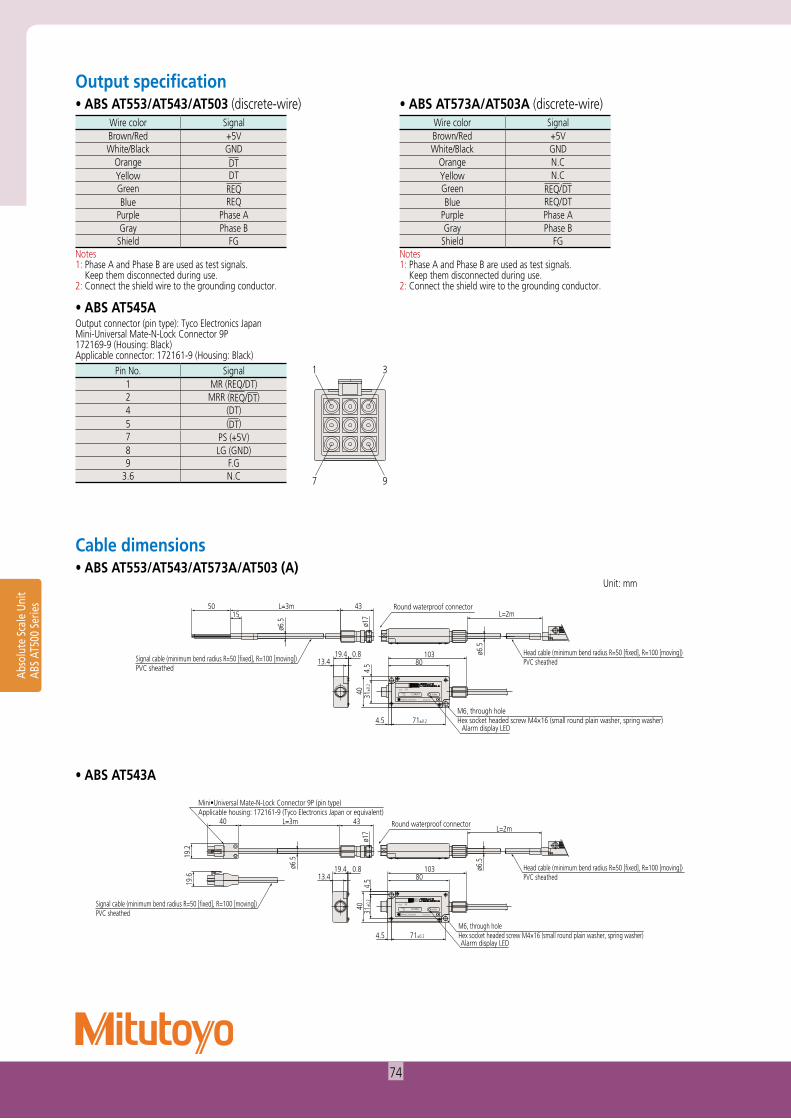
• ABS AT553/AT543/AT503 (discrete-wire)
• ABS AT545A
• ABS AT553/AT543/AT573A/AT503 (A)
• ABS AT543A
• ABS AT573A/AT503A (discrete-wire)Output specification
Cable dimensions
Wire color SignalBrown/Red +5VWhite/Black GND
Orange DTYellow DTGreen REQBlue REQ
Purple Phase AGray Phase B
Shield FGNotes1: Phase A and Phase B are used as test signals. Keep them disconnected during use.2: Connect the shield wire to the grounding conductor.
Output connector (pin type): Tyco Electronics JapanMini-Universal Mate-N-Lock Connector 9P172169-9 (Housing: Black)Applicable connector: 172161-9 (Housing: Black)
Pin No. Signal1 MR (REQ/DT)2 MRR (REQ/DT)4 (DT)5 (DT)7 PS (+5V)8 LG (GND)9 F.G
3.6 N.C
Wire color SignalBrown/Red +5VWhite/Black GND
Orange N.CYellow N.CGreen REQ/DTBlue REQ/DT
Purple Phase AGray Phase B
Shield FGNotes1: Phase A and Phase B are used as test signals. Keep them disconnected during use.2: Connect the shield wire to the grounding conductor.
74
Effective range L0
4.5
L4
Maximum travel length L1
ABS zero point, base position
Alarm display LED
ø6.5
0.819.4 (103)80
71±0.2
31±0
.240
4.5
9284
L2
23
15.7
13.4
(L3)
Details of elastically secured portion
Stainless steel bushingAluminum frame
Hex socket headed screw M4×25(small round plain washer, spring washer)
Special leaf spring
*Mounting mating surface
1.5±0
.2(G
ap be
twee
n dete
ctor h
ead
and a
luminu
m fra
me)1±0.1
(Step between detector head and aluminum frame)
*Adju
sted w
ith sp
ecial
jig
*Special leaf spring used (long dashed double-dotted line)
1234567
1234567
ALARM
AT���
Mitutoyo Corporation
AT500AIR
(P±0.2×n)
(Detector head)
(Aluminum frame)
P0.10.05/500
Q
G
G0.05/5000.1
R
0.1 P
*Aluminum frame surface
*Aluminum frame surface
*Mounting mating surface
R0.1*Longitudinal direction
S
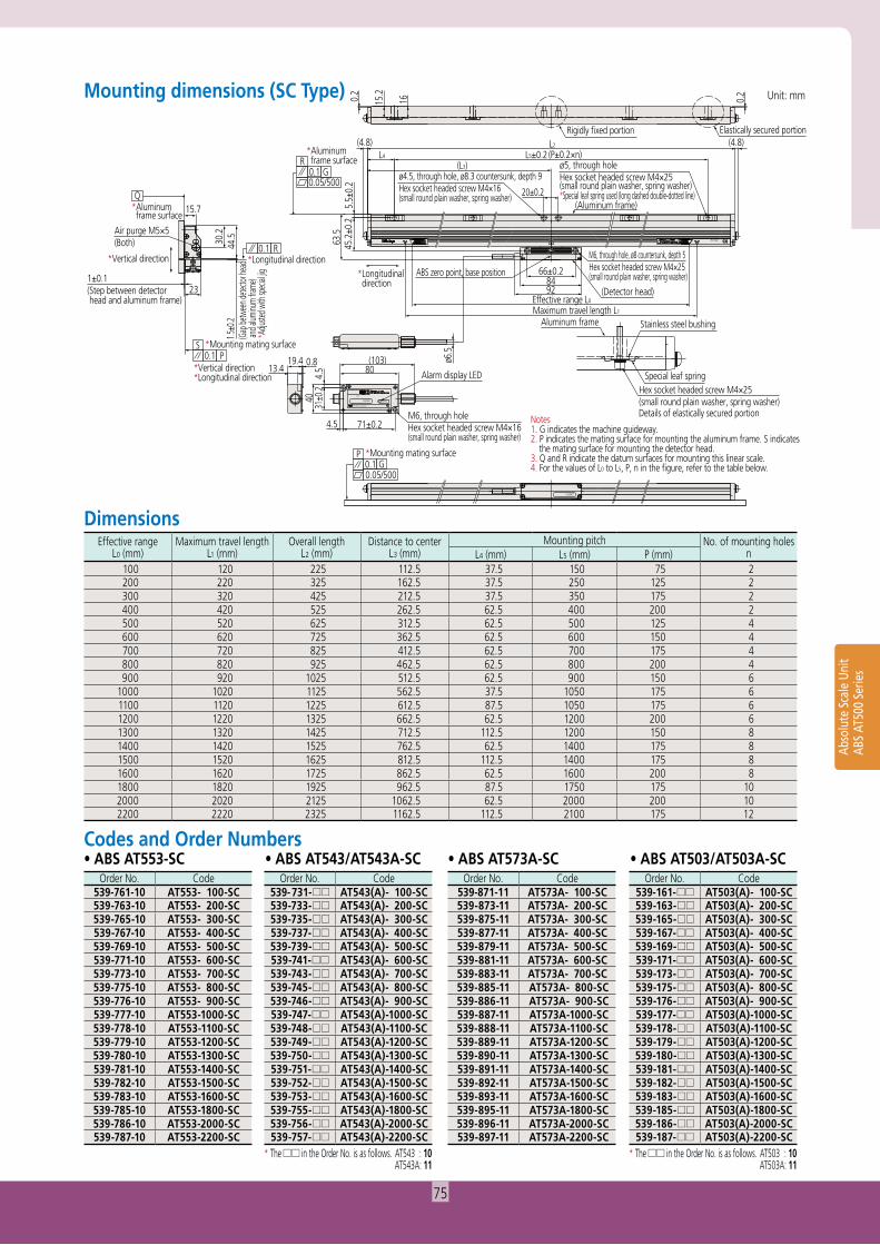
Notes1. G indicates the machine guideway.2. P indicates the mating surface for mounting the aluminum frame. S indicates
the mating surface for mounting the detector head.3. Q and R indicate the datum surfaces for mounting this linear scale.4. For the values of L0 to L5, P, n in the figure, refer to the table below.
Rigidly fixed portion Elastically secured portion
1615.20.2
0.2
Air purge M5×5(Both)
*Vertical direction
*Vertical direction*Longitudinal direction
44.530
.2
(4.8) (4.8)
5.5±
0.2
L5±0.2
20±0.2
66±0.2
45.2
±0.2
63.5
*Longitudinal direction
ø4.5, through hole, ø8.3 countersunk, depth 9Hex socket headed screw M4×16(small round plain washer, spring washer)
M6, through hole, ø8 countersunk, depth 5Hex socket headed screw M4×25(small round plain washer, spring washer)
M6, through holeHex socket headed screw M4×16(small round plain washer, spring washer)
ø5, through holeHex socket headed screw M4×25(small round plain washer, spring washer)
Unit: mm
Abso
lute
Sca
le U
nit
ABS
AT50
0 Se
ries
Mounting dimensions (SC Type)
Dimensions
• ABS AT553-SC • ABS AT543/AT543A-SC • ABS AT503/AT503A-SC• ABS AT573A-SCCodes and Order Numbers
Order No. Code539-761-10 AT553- 100-SC539-763-10 AT553- 200-SC539-765-10 AT553- 300-SC539-767-10 AT553- 400-SC539-769-10 AT553- 500-SC539-771-10 AT553- 600-SC539-773-10 AT553- 700-SC539-775-10 AT553- 800-SC539-776-10 AT553- 900-SC539-777-10 AT553-1000-SC539-778-10 AT553-1100-SC539-779-10 AT553-1200-SC539-780-10 AT553-1300-SC539-781-10 AT553-1400-SC539-782-10 AT553-1500-SC539-783-10 AT553-1600-SC539-785-10 AT553-1800-SC539-786-10 AT553-2000-SC539-787-10 AT553-2200-SC
Order No. Code539-731- AT543(A)- 100-SC539-733- AT543(A)- 200-SC539-735- AT543(A)- 300-SC539-737- AT543(A)- 400-SC539-739- AT543(A)- 500-SC539-741- AT543(A)- 600-SC539-743- AT543(A)- 700-SC539-745- AT543(A)- 800-SC539-746- AT543(A)- 900-SC539-747- AT543(A)-1000-SC539-748- AT543(A)-1100-SC539-749- AT543(A)-1200-SC539-750- AT543(A)-1300-SC539-751- AT543(A)-1400-SC539-752- AT543(A)-1500-SC539-753- AT543(A)-1600-SC539-755- AT543(A)-1800-SC539-756- AT543(A)-2000-SC539-757- AT543(A)-2200-SC
* The in the Order No. is as follows. AT543 : 10 AT543A: 11
Order No. Code539-871-11 AT573A- 100-SC539-873-11 AT573A- 200-SC539-875-11 AT573A- 300-SC539-877-11 AT573A- 400-SC539-879-11 AT573A- 500-SC539-881-11 AT573A- 600-SC539-883-11 AT573A- 700-SC539-885-11 AT573A- 800-SC539-886-11 AT573A- 900-SC539-887-11 AT573A-1000-SC539-888-11 AT573A-1100-SC539-889-11 AT573A-1200-SC539-890-11 AT573A-1300-SC539-891-11 AT573A-1400-SC539-892-11 AT573A-1500-SC539-893-11 AT573A-1600-SC539-895-11 AT573A-1800-SC539-896-11 AT573A-2000-SC539-897-11 AT573A-2200-SC
Order No. Code539-161- AT503(A)- 100-SC539-163- AT503(A)- 200-SC539-165- AT503(A)- 300-SC539-167- AT503(A)- 400-SC539-169- AT503(A)- 500-SC539-171- AT503(A)- 600-SC539-173- AT503(A)- 700-SC539-175- AT503(A)- 800-SC539-176- AT503(A)- 900-SC539-177- AT503(A)-1000-SC539-178- AT503(A)-1100-SC539-179- AT503(A)-1200-SC539-180- AT503(A)-1300-SC539-181- AT503(A)-1400-SC539-182- AT503(A)-1500-SC539-183- AT503(A)-1600-SC539-185- AT503(A)-1800-SC539-186- AT503(A)-2000-SC539-187- AT503(A)-2200-SC
* The in the Order No. is as follows. AT503 : 10 AT503A: 11
Effective rangeL0 (mm)
Maximum travel lengthL1 (mm)
Overall lengthL2 (mm)
Distance to centerL3 (mm)
Mounting pitch No. of mounting holesnL4 (mm) L5 (mm) P (mm)
100 120 225 112.5 37.5 150 75 2200 220 325 162.5 37.5 250 125 2300 320 425 212.5 37.5 350 175 2400 420 525 262.5 62.5 400 200 2500 520 625 312.5 62.5 500 125 4600 620 725 362.5 62.5 600 150 4700 720 825 412.5 62.5 700 175 4800 820 925 462.5 62.5 800 200 4900 920 1025 512.5 62.5 900 150 6
1000 1020 1125 562.5 37.5 1050 175 61100 1120 1225 612.5 87.5 1050 175 61200 1220 1325 662.5 62.5 1200 200 61300 1320 1425 712.5 112.5 1200 150 81400 1420 1525 762.5 62.5 1400 175 81500 1520 1625 812.5 112.5 1400 175 81600 1620 1725 862.5 62.5 1600 200 81800 1820 1925 962.5 87.5 1750 175 102000 2020 2125 1062.5 62.5 2000 200 102200 2220 2325 1162.5 112.5 2100 175 12
75
4.5
22
13.4 80(103)19.4 0.8
29
17.58
L2
8
11.6
24
Elastically secured portionElastically secured portionRigidly fixed portion
Mitutoyo Corporation
AT���
ALARM1234567
(Scale unit)
1234567
Cumulative tolerance for L5 and L6: ±0.3
AT500
P0.1 G0.05/1000
*Mounting mating surface
R
0.05/1000G0.1
*Aluminum frame surface
Q *Mounting block surface
(Mounting block)(Mounting block)(Mounting block)(Mounting block)
(Mounting block)
S0.1 P
*Mounting mating surface
0.1 R
Notes 1. G indicates the machine guideway.2. P indicates the mating surface for mounting the unit. S indicates the mating
surface for mounting the detector head.3. Q and R indicate the datum surfaces for mounting this linear scale.4. For the values of L0 to L6 in the figure, refer to the table below.
Air purge M5×5(Both)
*Vertical direction
Step between detector head and aluminum frame
1.6±0.1
27.8
(6.7
)36
.8(6
2)
3.2±
0.1
17.9
±0.1
24.1
±0.1
0.5
(4.3)
L5±0.2L4±0.3
L6±0.2
L3±0.3
L6±0.2
7.2
35.8
ø4.6Hex socket headed screw M4x25(small round plain washer, spring washer)
(4.3)
ø7.5, through hole, ø14 countersunk, depth 9.5Hex socket headed screw M6×25(small round plain washer, spring washer)*Vertical direction
*Longitudinal direction
4.5
4031
±0.2
71±0.2
Alarm display LED
M6, through holeHex socket headed screw M4×16(small round plain washer, spring washer)
ø6.5
8492
Effective range L0
Maximum travel length L1
54.8
1.5±
0.2 66±0.2
*Longitudinal direction
Gap be
tween
detect
or hea
d and
alumin
um fra
me
(Detector head)
M6, through hole, ø8 countersunk, depth 5Hex socket headed screw M4x25(small round plain washer, spring washer)
ABS zero point, base position0.
623
Unit: mm
Abso
lute
Sca
le U
nit
ABS
AT50
0 Se
ries
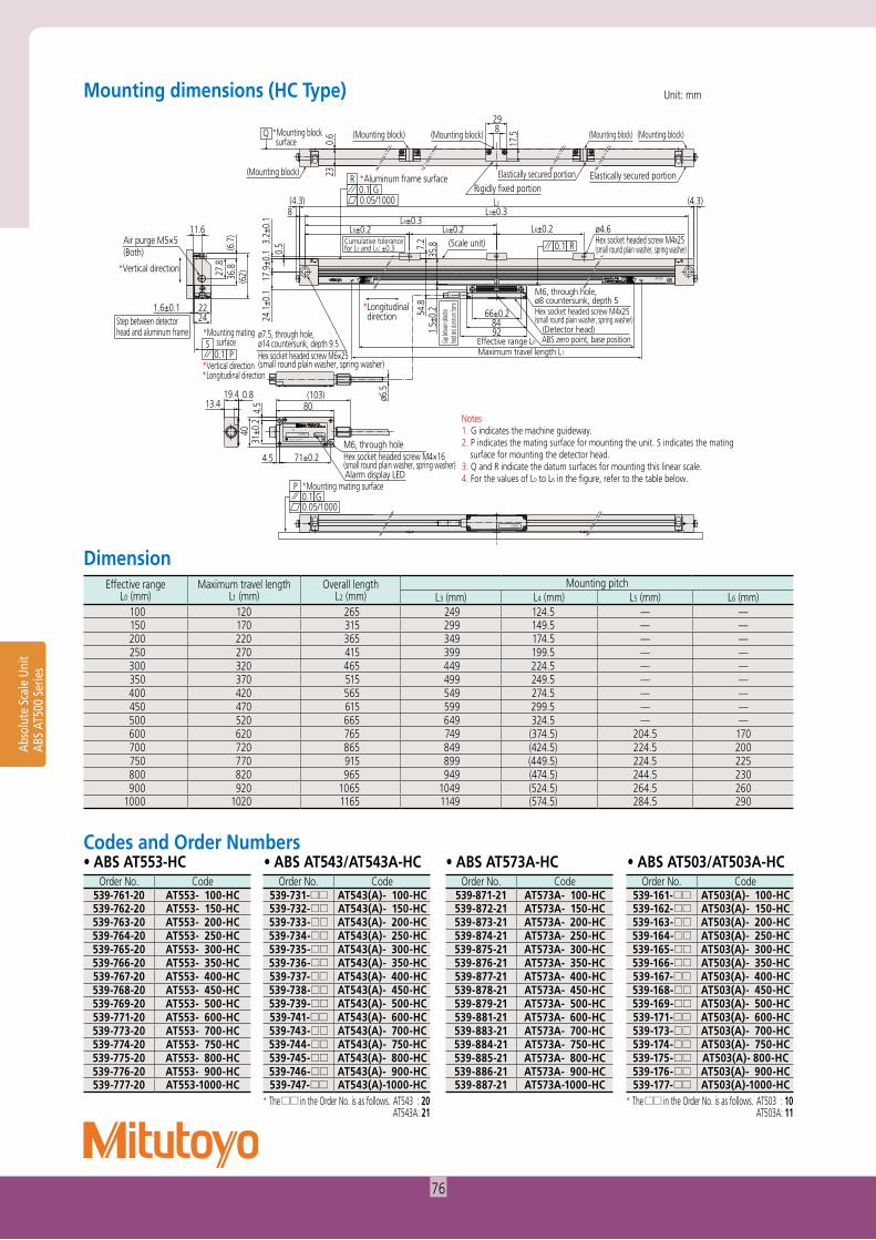
Mounting dimensions (HC Type)
Dimension
• ABS AT553-HC • ABS AT543/AT543A-HC • ABS AT503/AT503A-HC• ABS AT573A-HCCodes and Order Numbers
Order No. Code539-761-20 AT553- 100-HC539-762-20 AT553- 150-HC539-763-20 AT553- 200-HC539-764-20 AT553- 250-HC539-765-20 AT553- 300-HC539-766-20 AT553- 350-HC539-767-20 AT553- 400-HC539-768-20 AT553- 450-HC539-769-20 AT553- 500-HC539-771-20 AT553- 600-HC539-773-20 AT553- 700-HC539-774-20 AT553- 750-HC539-775-20 AT553- 800-HC539-776-20 AT553- 900-HC539-777-20 AT553-1000-HC
Order No. Code539-731- AT543(A)- 100-HC539-732- AT543(A)- 150-HC539-733- AT543(A)- 200-HC539-734- AT543(A)- 250-HC539-735- AT543(A)- 300-HC539-736- AT543(A)- 350-HC539-737- AT543(A)- 400-HC539-738- AT543(A)- 450-HC539-739- AT543(A)- 500-HC539-741- AT543(A)- 600-HC539-743- AT543(A)- 700-HC539-744- AT543(A)- 750-HC539-745- AT543(A)- 800-HC539-746- AT543(A)- 900-HC539-747- AT543(A)-1000-HC
* The in the Order No. is as follows. AT543 : 20 AT543A: 21
Order No. Code539-871-21 AT573A- 100-HC539-872-21 AT573A- 150-HC539-873-21 AT573A- 200-HC539-874-21 AT573A- 250-HC539-875-21 AT573A- 300-HC539-876-21 AT573A- 350-HC539-877-21 AT573A- 400-HC539-878-21 AT573A- 450-HC539-879-21 AT573A- 500-HC539-881-21 AT573A- 600-HC539-883-21 AT573A- 700-HC539-884-21 AT573A- 750-HC539-885-21 AT573A- 800-HC539-886-21 AT573A- 900-HC539-887-21 AT573A-1000-HC
Order No. Code539-161- AT503(A)- 100-HC539-162- AT503(A)- 150-HC539-163- AT503(A)- 200-HC539-164- AT503(A)- 250-HC539-165- AT503(A)- 300-HC539-166- AT503(A)- 350-HC539-167- AT503(A)- 400-HC539-168- AT503(A)- 450-HC539-169- AT503(A)- 500-HC539-171- AT503(A)- 600-HC539-173- AT503(A)- 700-HC539-174- AT503(A)- 750-HC539-175- AT503(A)- 800-HC539-176- AT503(A)- 900-HC539-177- AT503(A)-1000-HC
* The in the Order No. is as follows. AT503 : 10 AT503A: 11
Effective rangeL0 (mm)
Maximum travel lengthL1 (mm)
Overall lengthL2 (mm)
Mounting pitchL3 (mm) L4 (mm) L5 (mm) L6 (mm)
100 120 265 249 124.5 — —150 170 315 299 149.5 — —200 220 365 349 174.5 — —250 270 415 399 199.5 — —300 320 465 449 224.5 — —350 370 515 499 249.5 — —400 420 565 549 274.5 — —450 470 615 599 299.5 — —500 520 665 649 324.5 — —600 620 765 749 (374.5) 204.5 170700 720 865 849 (424.5) 224.5 200750 770 915 899 (449.5) 224.5 225800 820 965 949 (474.5) 244.5 230900 920 1065 1049 (524.5) 264.5 260
1000 1020 1165 1149 (574.5) 284.5 290
76
4.5
22
0.819.4 (103)8013.4
(L4)8(4.3) (4.3)
8
17.5
29
230.
624
11.6
8492
Effective range L0
Maximum travel length L1
L2
Rigidly fixed portionElastically secured portion
Elastically secured portion Elastically secured portion
1234567 ALARM
AT���
Mitutoyo Corporation
Base position
(Mounting block)
(Mounting block)
Cumulative tolerance for L5 and L6: ±0.3
Notes 1. G indicates the machine guideway.2. P indicates the mating surface for mounting the unit. S indicates
the mating surface for mounting the detector head.3. Q and R indicate the datum surfaces for mounting this linear scale.4. For the values of L0 to L4 and L6 in the figure, refer to the table
below.
*Longitudinal direction
*Vertical direction
Step between detector head and aluminum frame
R0.1
*Mounting mating surfaceP0.1
S
*Mounting block surface
Q
*Aluminum frame surface0.1 G0.05/1000
R
*Mounting mating surface
0.05/1000G0.1
P
AT500
1234567
(Detector head)ABS zero point, base position
(Scale unit)
(Mounting block) (Mounting block)
ø7.5, through hole, ø14 countersunk, depth 9.5Hex socket headed screw M6×25(small round plain washer, spring washer)
ø4.6Hex socket headed screw M4×25 (small round plain washer, spring washer)
L3±0.3
L6±0.274.5±0.2 (L5)
7.2
35.8
3.2±
0.1
17.9
±0.1
24.1
±0.1
Gap bet
ween de
tector
head an
d alumi
num fra
me
0.5
M6, through hole, ø8 countersunk, depth 5Hex socket headed screw M4x25(small round plain washer, spring washer)54
.81.
5±0.
2
66±0.2
Air purge M5×5(Both)
*Vertical direction*Longitudinal direction
(6.7
)36
.827
.8
(62)
1.6±0.1
31±0
.240
4.5
71±0.2
Alarm display LED
M6, through holeHex socket headed screw M4×16(small round plain washer, spring washer)
ø6.5
Unit: mm
Abso
lute
Sca
le U
nit
ABS
AT50
0 Se
ries
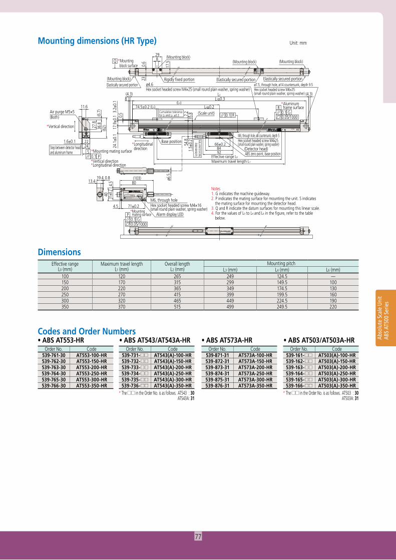
Mounting dimensions (HR Type)
Dimensions
• ABS AT553-HR • ABS AT543/AT543A-HR • ABS AT503/AT503A-HR• ABS AT573A-HRCodes and Order Numbers
Order No. Code539-761-30 AT553-100-HR539-762-30 AT553-150-HR539-763-30 AT553-200-HR539-764-30 AT553-250-HR539-765-30 AT553-300-HR539-766-30 AT553-350-HR
Order No. Code539-731- AT543(A)-100-HR539-732- AT543(A)-150-HR539-733- AT543(A)-200-HR539-734- AT543(A)-250-HR539-735- AT543(A)-300-HR539-736- AT543(A)-350-HR
* The in the Order No. is as follows. AT543 : 30 AT543A: 31
Order No. Code539-871-31 AT573A-100-HR539-872-31 AT573A-150-HR539-873-31 AT573A-200-HR539-874-31 AT573A-250-HR539-875-31 AT573A-300-HR539-876-31 AT573A-350-HR
Order No. Code539-161- AT503(A)-100-HR539-162- AT503(A)-150-HR539-163- AT503(A)-200-HR539-164- AT503(A)-250-HR539-165- AT503(A)-300-HR539-166- AT503(A)-350-HR
* The in the Order No. is as follows. AT503 : 30 AT503A: 31
Effective rangeL0 (mm)
Maximum travel lengthL1 (mm)
Overall lengthL2 (mm)
Mounting pitchL3 (mm) L4 (mm) L6 (mm)
100 120 265 249 124.5 —150 170 315 299 149.5 100200 220 365 349 174.5 130250 270 415 399 199.5 160300 320 465 449 224.5 190350 370 515 499 249.5 220
77
4.5
404.
531
±0.2
71±0.2
22
0.819.4 (103)80
Alarm display LED
M6, through holeHex socket headed screw M4×16(small round plain washer, spring washer)
13.4
(L4)
24
11.6Air purge M5×5(Both)
Step between detector head and aluminum frame
8492
Effective range L0
Maximum travel length L1
L2
7.2
54.8
1.5±
0.2
35.8
L3±0.3
L6±0.2
66±0.2
74.5±0.2 (L5)
298
8
Elastically secured portion(4.3) (4.3)
Elastically secured portionø4.6Hex socket headed screw M4×25 (small round plain washer, spring washer)
1234567 ALARM
AT���
Mitutoyo Corporation
Base position
Cumulative tolerance for L5 and L6: ±0.3
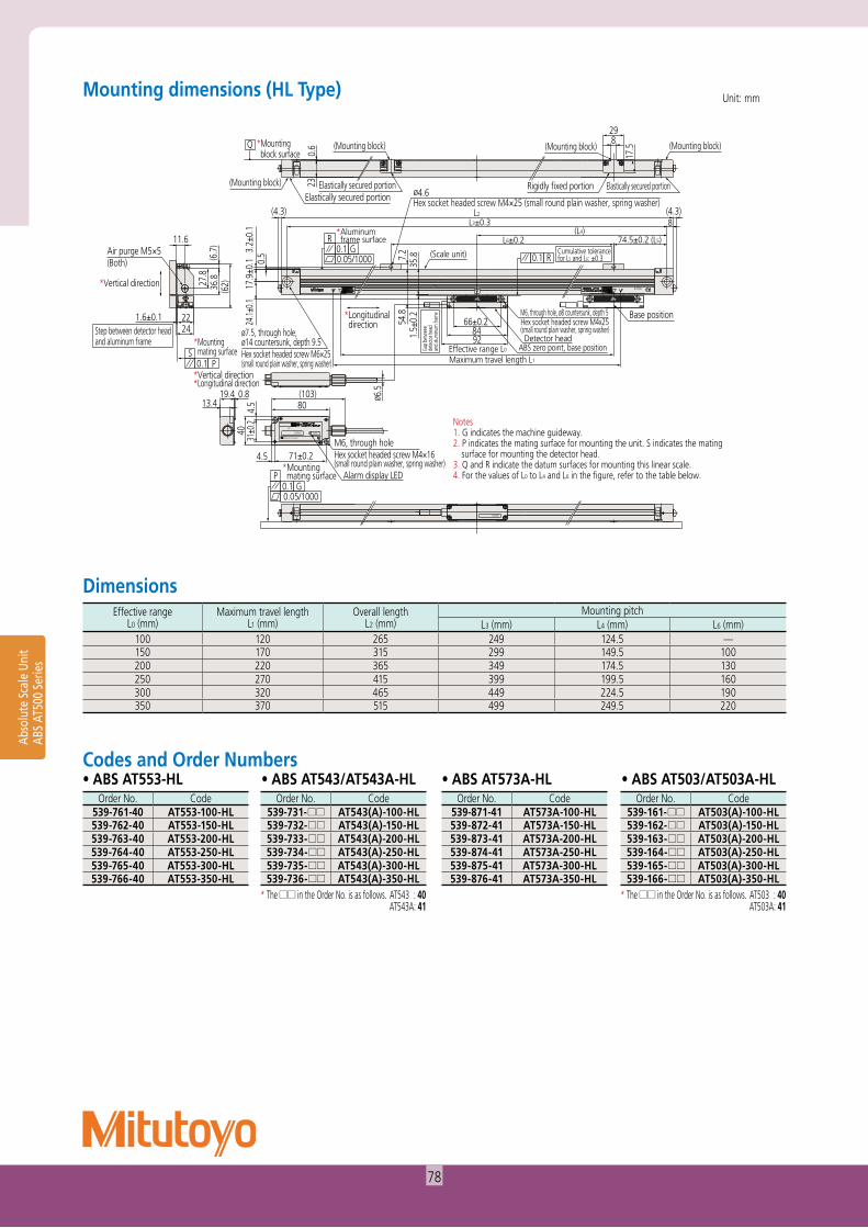
Notes1. G indicates the machine guideway.2. P indicates the mating surface for mounting the unit. S indicates the mating
surface for mounting the detector head.3. Q and R indicate the datum surfaces for mounting this linear scale.4. For the values of L0 to L4 and L6 in the figure, refer to the table below.
*Longitudinal direction
*Vertical direction
R0.1
*Mounting mating surface
*Vertical direction*Longitudinal direction
P0.1S
(Mounting block)
(Mounting block)*Mounting block surface 0.
6
3.2±
0.1
17.9
±0.1
24.1±
0.1
Gap
betw
een
dete
ctor h
ead
and
alum
inum
fram
e
ø 6.5
0.5(6.7
)36
.827.8
(62)
23
Q
*Aluminum frame surface
ø7.5, through hole, ø14 countersunk, depth 9.5Hex socket headed screw M6×25(small round plain washer, spring washer)
0.1 G0.05/1000
R
*Mounting mating surface
0.05/1000G0.1
P
AT500
1234567
Detector head
M6, through hole, ø8 countersunk, depth 5Hex socket headed screw M4x25(small round plain washer, spring washer)
ABS zero point, base position
(Scale unit)
Elastically secured portionRigidly fixed portion
(Mounting block)
17.5(Mounting block)
1.6±0.1
Unit: mmMounting dimensions (HL Type)
Dimensions
• ABS AT553-HL • ABS AT543/AT543A-HL • ABS AT503/AT503A-HL• ABS AT573A-HLCodes and Order Numbers
Order No. Code539-761-40 AT553-100-HL539-762-40 AT553-150-HL539-763-40 AT553-200-HL539-764-40 AT553-250-HL539-765-40 AT553-300-HL539-766-40 AT553-350-HL
Order No. Code539-731- AT543(A)-100-HL539-732- AT543(A)-150-HL539-733- AT543(A)-200-HL539-734- AT543(A)-250-HL539-735- AT543(A)-300-HL539-736- AT543(A)-350-HL
* The in the Order No. is as follows. AT543 : 40 AT543A: 41
Order No. Code539-871-41 AT573A-100-HL539-872-41 AT573A-150-HL539-873-41 AT573A-200-HL539-874-41 AT573A-250-HL539-875-41 AT573A-300-HL539-876-41 AT573A-350-HL
Order No. Code539-161- AT503(A)-100-HL539-162- AT503(A)-150-HL539-163- AT503(A)-200-HL539-164- AT503(A)-250-HL539-165- AT503(A)-300-HL539-166- AT503(A)-350-HL
* The in the Order No. is as follows. AT503 : 40 AT503A: 41
Effective rangeL0 (mm)
Maximum travel lengthL1 (mm)
Overall lengthL2 (mm)
Mounting pitchL3 (mm) L4 (mm) L6 (mm)
100 120 265 249 124.5 —150 170 315 299 149.5 100200 220 365 349 174.5 130250 270 415 399 199.5 160300 320 465 449 224.5 190350 370 515 499 249.5 220
Abso
lute
Sca
le U
nit
ABS
AT50
0 Se
ries
78