Embed Size (px)
Citation preview
ABSOLUTE MEASUREMENTS OF THE ACTIVITY OF RADIONUCLIDES
I - The Defined Solid Angle Method with Geiger Mflller Counters
Dagmar C. C. Reis and Lais P. de Moura Absolute Measurements Laboratory - Nuclear Physios Division
I.E.A.
Divisao de Flsica Nuclear Instituto de Energia Atomica
Sao Paulo - Brasil
Publioagao IEA n? Ilk
Dezembro - 1 9 0
C O W S S A O N A C I O N M D E N U O E M V S P - f f i l
ABSOLUTE MEASUREMENTS OF THE ACTIVITY OF RADIONUCLIDES
I - The Defined Solid Angle Method with Gelger Mflller Counters
Dagmar C. C Reis and Lais P. de Moura Absolute Measurements Laboratory - Nuclear Physios Division
I.E.A.
Divisao de Ffsica Nuclear Instituto de Energia Atomica
Sao Paulo - Brasil'
Publioagao IEA n9 Ilk
Dezembro - 1965
C O M I S S X O W A C I O N A L D E C ^
Comissão Nacional de Energia Nuclear
Presidente: Prof. Luiz Cintra do Prado
Universidade de Sao Paulo
Reitor: Prof. Luiz Antonio da Gama e Silva
Instituto de Energia Atómica
Diretor: Prof. Rómulo Ribeiro Pieroni
Conselho Técnico-Científico do IEA
Prof. Hélio Lourenço de Oliveira ) ) pela USP
Prof. Walter Borzani )
Prof. Rui Ribeiro Franco ) ) pela CNEN
Prof. Theodoreto H.I. de Arruda Souto )
COMISSÃO NACIONAL DE ENERVA N1.ICLF.AR/SP-IPEM
ABSOLUTE MEASUREMENTS OF THE ACTIVITY OF RADIONUCLIDES
I - The Defined Solid Angle Method with Geiger MÜller Counters
by
Dagmar C. C. Heis and Lais P. de Moura
Absoluto Measurements Laboratory - Nuclear Physlos Division
I.E.A.
RESUMO
No- presente trabalho, os autores descrevem o sistema de
medidas absolutas de atividades de radionuclídeos por meio de con
tadores Geiger MÜller, com angulo sólido definido em relação à
fonte. 0 sistema empregado no Laboratório de Medidas Absolutas dá
Divisão de Física Nuclear do IEA é objeto de discussão pormenori
zada e é dada ênfase especial à neoessidade de fixar a geometria
do sistema e o tempo morto independentemente do contador.
Apesar de sua precisão ser limitada, o sistema apresen
ta vantagens pela sua simplicidade e estabilidade e é suscetível
de fornecer resultados de apreciável precisão desde que os diver
sos fatores que afetam as medidas sejam determinados cuidadosamen
te.
RESUME
Dans ce travail est présentée la méthode du compteur
Geiger MÜller avec angle solide défini, pour la mesure absolue de
radionuclides. On décrit le système utilisé au Laboratoire de Me
sures Absolues de cet Institut, dans lequel la géométrie et le
temps mort son définis indépendamment du compteur. D'autre part,
on analyse soigneusement les facteurs qui affectent l'efficacité
totale du système.
. 2 .
Bien que la précision de cette méthode soit limitée, el
le est cependant très suffisante pour des mesures de routine. ,
étant donnée sa simplicité.
ABSTRACT
In this paper a detailed account of the defined solid
angle method with Geiger Mûller counters is presented, as used at
the absolute measurements laboratory of this Institute. A system
is described in which both the geometry and dead time are defined
independently of the counter and the influence of the different
factors which affect the overall efficiency is analysed.
Because of its reliability and simplicity the method is
largely used for routine measurements, in spite of its limited
precision.
INTRODUCTION
There is a wide field of nuclear research In which the
absolute disintegration rate of a radioactive source need only be
known approximately in order to design experiments and in which
only relative measurements need be made with any degree of
precision.
There are, however, a few important applications which
demand a precise knowledge of the disintegration rate.
As a general rule, those are the problems in which the
radiations emitted by a source are used as projectiles and not
merely as units to be counted. Problems such as the determination
of the neutron flux, the absolute measurement of the number of
neutrons or gamma rays emitted by a source, nuclear cross-sections
measurements, the determination of the disintegration constants of
radioactive nuclides, fission product studies and so on. In the
problems of nuclear energy, where a precise knowledge of the
nuclear constants of several materials used in moderators, fuel
. 3 •
elements, structural materials and others, the influence of small uncertainties in the value of those parameters can affect seriously the results of the calculations and reactor design.
Due to the complexities involved In the precise determina tion of the absolute disintegration rate and the consideration that there is already a wide field of activities which require the determination of the counting rate of a source with a fairly good degree of accuracy, such as its applications in soil and fertilizer research, in measurements of the metabolic rate of isotopes or labeled molecules etc., the need has arisen of fabricating reference standard sources of several nuclides. Since through the use of such standard sources accurate measurements of the disintegration rate of an unknown source can be made with a end window Geiger Mttller counter if special precautions are taken, a detailed knowledge of the physical and geometric factors which influence such measurements is necessary.
The absolute measurement of the disintegration rate of a radioactive nuclide has the main purpose of obtaining, with the maximum possible accuracy, the specific disintegration rate of the isotope under study.
Whenever a radioactive source is being measured in a © counting system it is imperative that the efficiency of the system be known accurately. Such an efficiency can be evaluated by the knowledge of several factors which influence the measurements and which can be fairly well calculated when the characteristics of the measuring system and the disintegration scheme of the radionuclide are known. Whenever a very high degree of accuracy is wanted, however, the use of special and delicate techniques used in the preparation of the sources, of particle detectors specially designed for that purpose and the use of suitable electronic systems, allow measurements with an efficiency much higher than the one obtained with the conventional Geiger Mttller counter system.
COMISSAONACIONALDEENEWtAWJCLEAR/SP-IPEN..
k
The most suitable method of measurement to be used for that purpose depends on the properties of the nuclide under study and a previous knowledge of its disintegration scheme is imperative.
For the measurement of beta active nuclides, the use of the method of the defined solid angle with Geiger Muller counters, described in this paper, will allow measurements to be made with an accuracy between 5 and 10$ under the best experimental conditions; its main merit is, however, its extreme simplicity and the high accuracy of the results which can be obtained when only relative measurements are the main purpose of an experiment.
The use of a hXi proportional counter shows a much higher accuracy (between 1$ and yf>) but the measurements require special techniques for the preparation of the sources.
When the nuclide under study emits beta rays followed by gamma rays the use of the method of coincidences between the beta and the gamma rays, as measured in a hu beta-gamma system gives the highest accuracy obtainable to date (of the order of 0.1$),but it involves the same care in the preparation of samples which is required for the kn counting systems.
The properties and main characteristics of the proportional ki\ counting system, of a 2 ff beta-gamma coincidence system and the techniques used in the preparation of sources and in the preparation of thin films for source deposition, used at the IEA will be described in other publications.
GETGER-MflT.LKR COUNTER WITH DEFINED GEOMETRY In the measurements of activities with a Geiger Mttller
end window counter, there are several factors which must be taken into account in order that the absolute activity of the source can be evaluated. Among those, the geometry factor is the most difficult to be evaluated due to uncertainties in the determination
of the sensitive volume of the counter. One way to overcome this difficulty is to allow only a cone of particles to reach the counter in the neighbourhood of the wire^1^. Die geometry of the system can be very accurately known and the uncertainties due to the sensitive region of the counter eliminated by providing the counting system with a ciroular diaphragm provided with a central circular hole, of a diameter somewhat smaller than that of the counter, located between the source and the counter window, so as to allow only particles within a narrow cone to reach the counter window. Such a baffle plate is usually made of brass and its thickness should be sufficiently large to absorb all the beta rays emitted by the source which should not reach the counter sensitive area.
Another source of error are the losses due to the dead time of the counter, since it is known that it varies under the influence of factors such as the gas pressure inside the counter, the nature of the gases used in filling the counter, the value of the potential applied between the counter cathode and anode, the age of the counter and also the counting rate. Since the correction of those factors is difficult, the electronic counting circuit is usually provided with a gate that blocks the counter operation during a time interval not smaller than its dead time.
EXPERIMENTAL ARRANGEMEMT (fig. l)
The Geiger Mttller tube used is a type I8526 (Philips), of 27 mm of diameter and provided with a mica window of 1,8 mg/cm. The counter is mounted inside a lead castle of 55 nan thickness, lined with 1 mm thick aluminium. The system is provided with an aluminium rack in which the baffle plate and the source holder can be placed in various positions, 1 cm apart from each other (fig.2). The 1,6 mm thick brass diaphragm is provided with a carefully machined hole of 18 mm diameter, and is located at 1 cm from the counter window (our lead castle is a standard Lemer Nantes, of the
COMiSSAQ NACIQNAL D£ FMfSf l t t M; if, F A p / c p m
6
same type made for the "Commissariat a. I 1 Sergio Atomique^, It is important to bear in mind that a precise evalua
tion of the geometry factor depends critically on the diameter of the diaphragm hole, an error of 0,1 mm in the value of its radius giving rise to an uncertainty of 2,5 # in the above factor.
ELECTRONIC SYSTEM The electronic system used is schematically represented
in figure 3. It consists essentially of. - Stabilized power supply (250 V. D.C.) type TALS. - Electronic timer, with a provision for pre-set time and pre-set count measurements (TTCPl).
- Scaler T2D1. - Geiger circuit TEGM-1. - Pre-amplifier for the Geiger tube (GMP 3) .
The unit TEGM-1 consists of the following main circuits: - A monostable trigger circuit to define the dead time (overall).
- A circuit for lowering the potential applied on the wire after a pulse is counted.
- A high voltage stabilized circuit. - Au output circuit to operate the mechanical register. - A control circuit. The main feature of this circuit is to help the quench
ing of discharge by lowering the potential applied in the counter wire (anode) during a pre-set time and to block the scaler input circuit during the same time interval. Since the potential drop at the tube anode is of about 400 volts, the Geiger Mttller counter becomes insensitive to any ionizing radiation which might enter the tube in this time interval. The dead time can be varied at will according to the following values? 100, 250, 500 and 1000 microseconds.
In our measurements, the dead time is usually fixed in 500 microseconds, since the tube dead time is of about 200 microseconds.
CORRECTION FACTORS
The real disintegration rate of a source can be evaluat ed by dividing the measured counting rate of the sample by the overall efficiency of the counting system.
D - C . (9)
£, can be calculatedv ' from the equation
e a f_ f f, f f. f S G m ? w b s where
e^ is the intrinsic efficiency of the detector for beta particles.
f^ is the geometry factor for the counting system, f is the factor due to multiple discharges in the Geiger
counter* f^ is the factor corresponding to the losses due to the
dead time of the counter, f is the factor corresponding to the absorption of the W
beta ray energy in the air layer between source and counter window and the window absorption.
ffe is the baok-scattering factor due to the source support. f ' is the self absorption factor due to the finite thick -s
ness of the source. There are other factors which are not taken in considers
tion due to their smallness when the counter system is lined with materials of a low atomic number, such as is the case in lead castles lined with aluminium or lucite and when the same materials are used in the construction of the source mounting trays and
COMiSSAO NACIONAL D E E N £ S « A N U C L E A R / S P - i P E M 1
8
racks. For the above reason, the Influence on the overall efficiency due to air scattering, scattering in the supporting frames and so on are neglected.
In the following lines the influence of the correction factors will be discussed with some detail.
a) Geiger Mflller,counter efficiency
For beta rays, of the energies usually found in radioisotope activity measurements, the efficiency of the Geiger counter is taken as
• f - 1
Biis value is a very good approximation for counters fill, ed with a gas pressure not smaller than 10 cm Hg of such an active*: length that the incoming particle travels not less than 2 cm through the sensitive volume of the counter which is assumed to show a good plateau.
b) Geometry factor
Although a source emits radiation with spherical symmetry (this is true only when both the source and its supporting film are of negligible thickness), only the rays emitted'within the solid angle subtended by the source and the detector and defined by the diaphragm are detected.
The geometry factor f„ is defined as the solid angle subtended between the counter and the source.
By assuming that the emission of the radiation by the source is spherically symmetrical about the source, its value gives the fraction of the emitted rays which can enter into the sensitive volume of the counter (neglecting the influence of other factors which will be taken into consideration later).
For a point source or for a source with a negligible
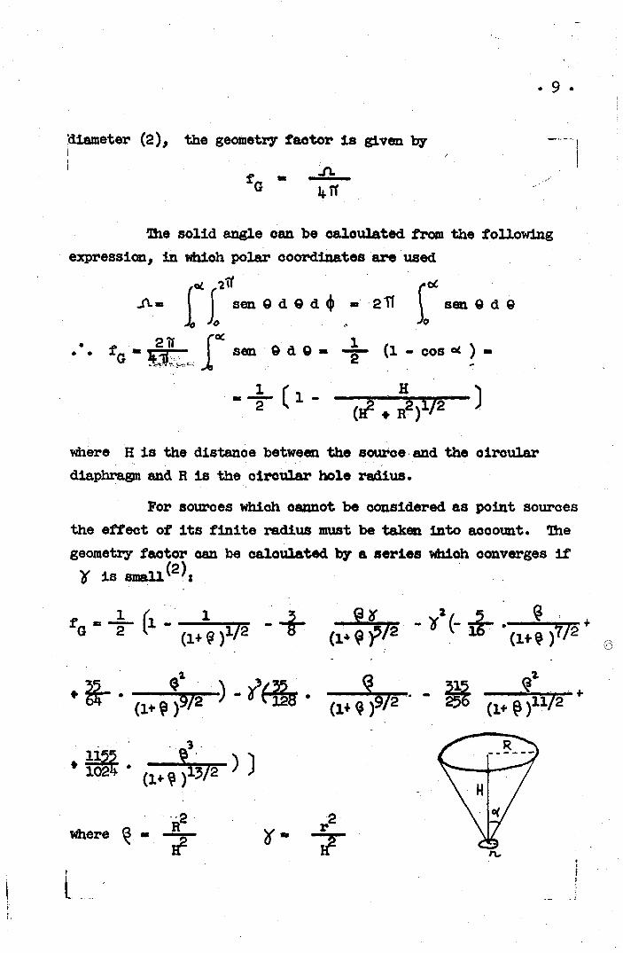
diameter (2), the geometry factor is given by -
' f - -CL. G 4 IT
Bie solid angle can be calculated from the following expression, in whioh polar coordinates are used
f* r a t f
sen 9 d 9 d (j) - 2 sen Q d 9 Jo
fG " l ^ - - ^ sen © d © - -|- (1 - cos « ) -
i -(H 2 . Ra)V2
where H is the distance between the source and the oiroular diaphragm and R is the oiroular hole radius.
For sources whioh oannot be considered as point sources the effect of its finite radius must be taken into aooount. 3he geometry factor can be calculated by a series whioh converges if y is small^j
' ) " ^ 2 * ' (i+^)9/2 ^ (l^) n/2
where ^ R a 2 7"
. 10 ,
In fig. If, one can see the variation of the geometry-factor with the distance between the source and the diaphragm. °) Factor due to multiple discharges in the Geiger Muller tube
The factor ftakes into account the increase in the counting rate due to multiple discharges in the Geiger Muller tube. It is known that this factor increases with the excess of voltage above the counter threshold, with the counter age (due to the decomposition of the quenching gas molecules under electrical discharges) and with the counting rate, since it is of a statistical naturej it is the main factor responsible, for the slope of the Geiger counter plateau. New counters with plateau showing a negligible slope should be used and the high voltage applied to the counter anode should be as stable as possible, in order to minimize the influence of those spurious discharges| under the above hypothesis we could take
as a very good approximation. The counting rates of the source should not be so large as to introduce errors due to its dead time, since the observation shows that, under those conditions, the probability of multiple pulse formation is negligible. d) Factor due to the dead time of the counter
The dead time of a counter is defined as the minimum time interval required by the counter to start a new avalanche after a discharge initiated by another particle has taken place.
During the time in which the electron avalanches are occuring, the counter is obviously insensitive to any ionizing particle which traverses its sensitive volume. After a discharge has taken place, the counter anode potential raises to its previous value exponentially with the time and it may occur that the field
1 1 ,
' . r i l l r . o t b e ivJly r o i t c - r e d bsy*cr-3 m o t h e r p a r t i c l e pi -cduocrs a f e w
l o r . v:r v ir :r . i? i t h e s c u r r ; ^ * D«s t o t h e p r&ce»23 o f t h e p o s i t i v e
i o - : s a n d / o r t h e t i r . i « t ' ^ ^ p i r o d f o r t h e snode t o r e a c h i t s f o r m e r
v a l u e . , r h v : )u?^o f o r c e d ;;tV:.r t h o s e c o n d i t i o n s w i l l h a v e a s n i l l e r
a m p l i t u d e <• s o t h a t t t u - o o v i i t i n g r a t e r e g i s t e r e d w i l l b e d e p e n d e n t
on t h e &ain o f t h e srt>3 I f y i n s s v & t a a . l a o r d e r t . - a v o i d t h i s
scivr-ca o f error, i t i s K - :ual t o p r e r i d * t h s c o u n t e r w i t h a q u e n c h
ing ; system w h i c h w i l l h . r e r i t a a n o d e p o t e n t i a l d u r i n g a t i m e
l a r g e r t h a n i t s i n t r i n s i c d e e d t i m e *
I t i s a l s o itfi;! "c tc ; ' t b t o b o a r tin m i n d t h a t t h e r e a r e
o t h e r p a r t s o f t h e ;;vu. i c i n g c i r c u i t w h i c h s h o w e. f i n i t e r e s o l u t i o n
t i m e w h i c h s h o u l d b ^ i n t o a c c o x m t . I n o r d e r t o e l i m i n a t e
G•..•>-!: s o u r c e : * o f o\- r e : . Mor i fa*; t o r s , i u i o u s u a l t o u s e t i m e
c o n s t a n t s :hi t h e e l s c t r o a i o .n .^cuxt .3 . - v . l l e r t h a n t h e t o t a l d e a d
t i m e c f t h e e . o u r . t e i s ' ^ l d ^ r t h o s e h y p o t h e s i s , t h e o n l y c o r r e c t i o n
r e c m i r & i i « t h e o n e h u e t o t h e f i n i t e d e a d t i m e o f t h e c o u n t e r „
h . l f; d i ' - , / ' > b s t h e t r u e c o u n t i n g r a t e o f t h e
?::cvj.*c^ ("••.-!-re t b - r ^ h l i r r . b ^ r o f p a r t i c l e s e m i t t e d b y t h e
i v x i r c e u . : d . r <.hc s r ^ l i d £ u i £ i s ^ u b x e n d e d b y "the e ^ u r t e r ? t h i s n u m b e r
v /ou ld b e .;\;/.u?J t o t h h i ^ c h - s r o f p a r t i c l e s r e g i s t e r e d i f n o l o s s e s
vre-.oe p r e c ^ r t ) ,
•h\e -ciirt* h i ; : ' i ' ^ t>hi A t h s c o « x t e r i s i a s o a s i t i v c i s
0 ? ' f s e c o n d . The; o f t u r t l e l * s l o ^ t i n e a c h s e c o n d i s
D O ? i b-jc t h i s a u t t h w i s -^quai. t o D~C S '
I; - C « 0 C £
v.'h'..-r-^ C i.a cho n'Mher- o f a g i s t e r a 1 . a r t i c l e s * We h a v e t h e n
12 .
'Kiere are several ways-by means of which the resolution time of the system can be measuredj among those deserve special consideration the methods of direct measurement of the dead time by means of an oscilloscope, the method of paired sources, the method of .the areas and the method of the radioactive decay of a strong source of short half-life<, She last two are the most interesting since they afford a simple way to determine the resolu tion time for sources of different disintegration rateso
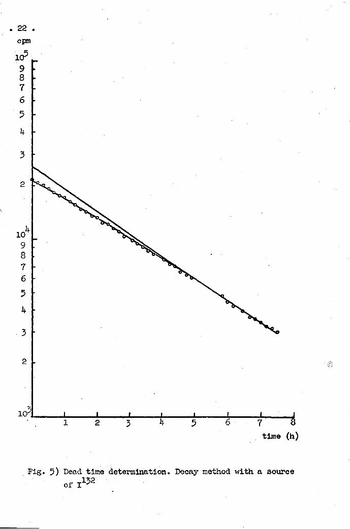
I. Method of the Fadioactiye Ifecay of a Source Since the activity of an isotope decays exponentially
with the time, a plot of the logarithm of the recorded intensity against time should appear as a straight line« However, if the source intensity is high enough, the recorded counting rates are smaller than what they should be owing to the finite resolution time of the equipment* As a result, the observed points lie below the straight line extrapolated towards the time t - 0. Die dead time of the system can be computed by taking into account the differences between the' observed and the true (extrapolated) counting rateso
In order to determine the resolving' time by this method, one should use a strong source (of the order of one microcurie) of an isotope of short lifea Figo 5 shows the results obtained with the decay of 1XJ&,
II... ^^^^^f_2ncreQ^ixi^ Areas If one considers a source uniformllly spread over an
area, the specific counting rate (that is, the counting rate per unit of area) should be a constant. Therofore_, by increasing the area of the source by known amounts, its activity should be proportional to the total area of the source«
Ihe recorded counting rate, however, follows this rule as a first approxijnation only, since a correction due to the
13
finite size of the source should be taken into account. In order to perform those measurements, it is important
to use radioactive sources with a fairly long half life, such as UX2 in equilibrium from a uranium oxide source. The results obtained with this source are represented in fig. 6.
Since the dead time of the counter depends on its counting rate and can vary with the time, it is a regular procedure to use an electronic circuit to make it a constant (usually slightly larger than the maximum dead time observed by one of the above methods). e) Absorption factor due to the air layer between the source and
the counter and the influence of the counter window. Before entering into the sensitive volume of the counter,
a particle emitted by the source will travel through the intervening air layer and the counter window before it can give'rise to a pair of ions in the counter filling gas.
Since the total equivalent thickness is small, the absorp_ tion can be calculated with a good approximation by the formula
f - e'^ st w 2
where M is the mass absorption coefficient (in cm /mg) and s. is 2
the total thickness of the absorbers (air plus window)(in mg/cm ). The absorption coefficient can be evaluated from empirical expressions:
JJ » 0,022 (Em)"*1'55 0,5 < Em < 6 Mev ref. (13) JJ- » 0,017 (Em)"1'^5 0,15 < Em < 3,5 Mev réf. (l) / ; = 0,0155 (Em)"1'1*1 ref. (8) / / = 0,0119 (Em)" 1' 8 5 ref. (12)
where Em is the maximum energy of the beta rays in Mev.
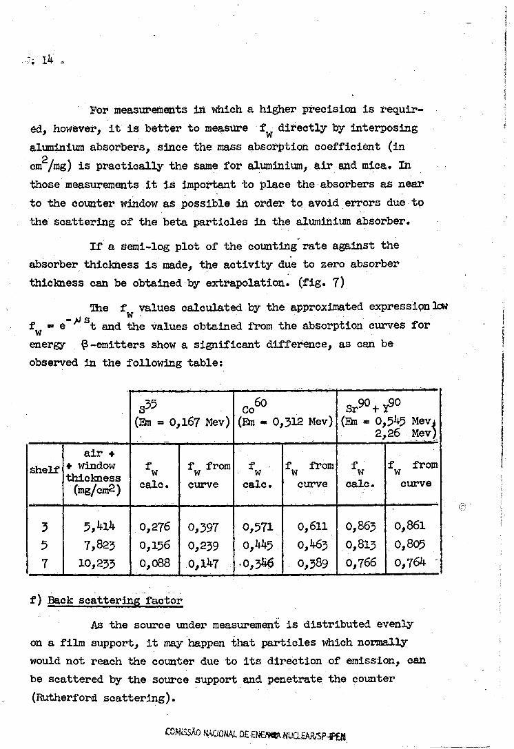
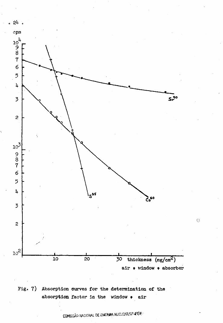
For measurements in which a higher precision is required, however, it is better to measure f directly by interposing
. • w aluminium absorbers, since the mass absorption coefficient (in cm /mg) is practically the Same for aluminium, air and mica. In those measurements it is important to place the absorbers as near to the counter window as possible in order to avoid errors due to the scattering of the beta particles in the aluminium absorber.
If a semi-log plot of the counting rate against the absorber thickness is made, the activity due to zero absorber thickness can be obtained by extrapolation, (fig. 7)
Ihe f values calculated by the approximated expression low f « e n t and the values obtained from the absorption curves for w energy £-emitters show a significant difference, as can be observed in the following table:
(Em = 0,167 Mev) n 60 Co (Em = 0,312 Mev) (Em - 0,545 Mev*
2,26 Mev)
shelf air •
• window thickness (ing/cm2)
f w
calc.
f from w curve
fw calc.
f from w curve
f w calc.
f from w curve
3 5,4l4 0,276 0,397 0,571 0,611 0,863 0,861
5 7,823 0,156 0,239 0,445 0,463 0,813 0,805
7 10,233 0,088 0,147 •0,340 0,389 0,766 0,764 -
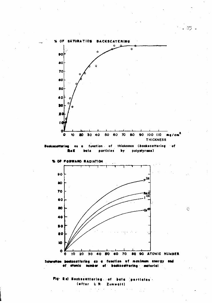
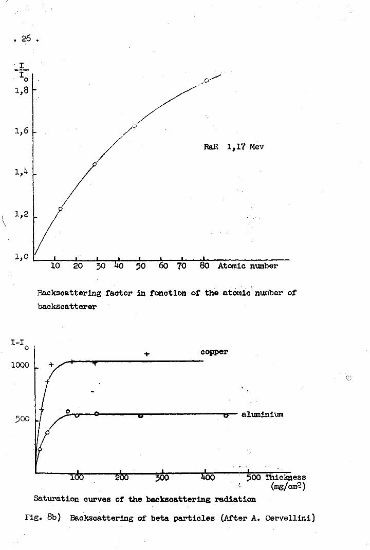
f) Back scattering factor
As the source under measurement is distributed evenly on a film support, it may happen that particles which normally would not reach the counter due to its direction of emission, can be scattered by the source support and penetrate the counter (Rutherford scattering).
. 15 -
The backscattering factor is, therefore, larger than one (usually its value is between 1 and 2, depending on the thick hess and on the atomic number of the source supporting film).
Since f changes rapidly with the support film thickness, i t is usual to employ either films of negligible thickness in order that ffe = 1, or infinitely thick (as compared with the particles range in the material) in order that the saturation backscattering factors found in tables can be used.
(a) Backscattering is estimated from the results of Zumwalt '
(Ik) and Cervellini ' whose curves are reproduced in fig. 8.
If one assumes for those corrections that the backing material is thin, then the percentage of the backscattered beta rays is a function only of its thickness in terms of an absorption half-thickness and, under those assumptions, the known results for polystyrene can be applied to any material.
g) Factor due to self-absorption
Since the sources always have a finite thickness, there are losses due to the absorption of emitted rays by the source material located between the disintegrating atom and the counter. This influence is greater when the maximum energy of the beta rays is small. ®
Let CQ be the counting rate per unit time under the hypothesis that the self absorption can be neglected. If one supposes that the thickness s of the souroe is uniform, the activity which goes through a layer of thickness dx at a distance x from the source will be:
C e- ' x . d c „ _° c ±2L-
The activity of the source at its surface will be
16
f can be directly measured by a number of diluted samples in
which the inactive material and the source material are mixed in
such a way that the total activity is maintained.
For absolute measurements, however, it is recommended
that special source preparation techniques be used so as to keep
f «=1: the use of carrier-free sources and a small amount of a s
wetting agent such as insulin will usually provide sources of a
high specific activity with a negligible self absorption. If a
thin support film is used, the influence of the two last factors
can be neglected.
PBETIMINARY MEASUREMENTS
In order to check the conditions of operation of the
counting system, there are some measurements which should be made
periodically.
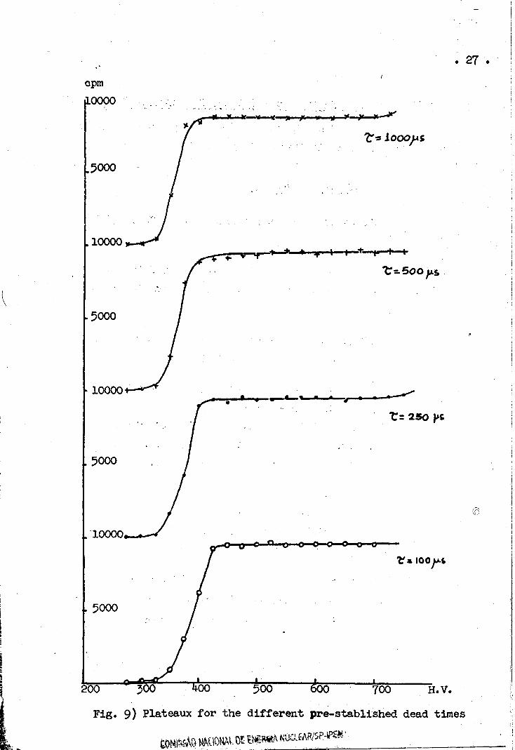
Plateaux The working condition of the Geiger MÜller tube can be
controlled periodically by determining its plateau (the
plot of the counting rate against the applied high voltage on the
counter wire) and observing its length and slope (fig* 9)» As it
is well-known, counters with deteriorated quenching mixture or
showing inhomogeneities in the wire surface will give rise to a
short plateau and a high slope due to the formation of multiple
discharges.
Statistical distribution A source of long half-life is used and
several measurements are made (obvious
ly, the larger the number of such measurements the better will be
' COMISSÃO NACIONAL DE EN£R«A NUCLEAR/SP-tPEN
. 17 .
the meaning of this test). When a source is not very active, the observed data will fit a Poisson distribution, whereas for strong sources a Gauss distribution is found. If a deviation of the statistical distribution is found, the equipment is not working properly.
Background All the counting systems show a certain background counting rate due to a number of causes such as
cosmic ray3, room and air or walls radioactivity due to natural radio-emitters, and contamination in the support, trays and walls of the counter.
The background counting rate is usually decreased by shielding the counter and source with a lead castle, lined with aluminium, lucite or other materials of low atomic number whose function is to absorb any ionizing particles from the lead contamination and to minimize scattering.
Periodical tests of the background counting rate will show, the casual presence of radioactive contamination in the counter system or a disturbance in the operating conditions of the pulse amplifying and registering systems.
The authors express their appreciation to Prof. M.D, de Souza Santos for many helpful suggestions and discussions, to Mr. José Ferreira for tho design and construction of several components at the IEA machine shop and to Miss Cleide Renner for her cooperation in making several measurements and calculations.
REFERENCES
1. Gleason.; Gol.î Taylor, J.D. ; Tabern, D.L. - "Absolute ? Counting at Defined Geometries" - Nuoleonics, 8, ne 5, PS« 12 (1951)-
. 18 .
2. Bsrtt , B.P. - "Absolute § •> r.t/>'. cloonics, 5 n* 2,
pg. 28 (August, 19^9).
3» Segre - E>rp-- Huele ¿r Physic^ .vol- 3 p?j, -\?fi,
if. Taylor a Í :7.¿v¡ - ri-Ih<3 Kea&urc-ff' .vt oi' ñ...ux ^.iotcp«=s".
5° Siguier, ,-Golds-nith - "Experimental lfc:3l*,va. 'es" - Mnohar-t &
Company, Xv>rîi_, ïfoir x-vl: - >üa Priuvixi;¿ «- i i ^ o ) .
6. Qldano, C.¿ Pnsquarelli, 'A. - "Self Abso^ n and Sslf-
-Scattering Sffects in Ç Particles Som*c&&* » Nuclear
Instruments and Methods 56 (190 ) pg* 3.92»
7. üpson, - "Beba Energ> Dependent la Er.d-\Ii.:dow íí,K- ï 'Aes"
ïïuoleonivVÍ„ vo l . 1 1 , Ir., y-> 49
8. Baker, RoG.j Katz, L . - S,.\scduic Ç Ccuutts.g of Kviclc Pl&nar Samples" - r.vilecnios 1 1 , : v r.. pg. 1 : (1>5~;).<
9. Zumwalt, L,R> - "Absolute § : ave ¿213 .-'.ra ¿ E>«d-Wiadov C»»M,
Counters and Experimental Lv-.ta o:,, $ - A'?:, .-ti-ola Seatiiring
Effects" - AECD - 567 (1950).
10. Gray - "General Crüv-.iples of Assay a:\i 3 ctuídardizaticn of
Radioactive Isotopos" - Bri t , I^cU B a l i , , 8, 115 (195?).
11 . Baptista, A . M . - ''"isdidas Absolutas de fíaSioauolídoos Snlssores
Beta" - Rev. Fao» 'Cienoie,s Lisboa ( 2 B ) .
12. Roalsvig, J , P . | Haslam, R„r.H. - , !/b-::.luts ( ; Counting !.n a
Proportional 3 ov--Cour.ter!; - aîaadiu.«. Jo-Atsaf.l of Physics, 3?
pg. IJ-99 (1959)«
13« Evans, R»D» - l?'i2iô Sc-.oaec and &tg!U:d<.-rl£g ..?f KvUIt-Jir ?o;^r ! i
(Addison-Vssl^y Press, Ctosbrid^s r^ss,) py, ;v3 (19**7 )«
Corvalliai , À. - "Estudo ¿a¿cx\CuVJLcito Áugular di Es?.dia«¿5-,o Beta" - c-aae - Escola Superior de Agriera tura "Luií- de Quoiroz" (1952). -
20
Power
T A U S - 2 50V
S c a \ « r * i revit"
TrcPi T 2^i * i revit"
Tri
Fig. Ja) Block diagram of the electronic system
Y* Pre-
MV.
circuit
v.
Output
Mono*-
J~L Clrewi+ fa*
lowering
4k* MV.
Fig. 3b) TECM - 1 unit
COMISSAO NACIONM. D£ ENEMA NUCLÉMVSP-«E«:
o 23. o
time (h)
Pig. 5) Dead time determination. Decay method with a source Of
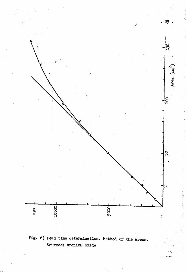
Fig. 6) Dead time determination. Method of the areas. Sources; uranium oxide
2k
îpm
10 20 30 thickness (mg/cnr) air t window * absorber
Fig. 7) Absorption ciurves for the determination of the absorption factor in the window * air
COMISSAO NACIONAL. DE ENBWW NUOEAR/SP-íW '
% Or SATURATION BACKSCATERIN6
0 K> 00 30 4 0 60 60 TO SO 90 100 (10 ma/em* THICKNESS
Boekocoffariaf. at a function of thickness (bacfcscaftorina of 11« I bata porticlos by potystyreaa)
% OP f OHWARO RADIATION
10 20 30 40 VO 60 • 0 90 ATOMIC NUMBER
SatartMo* »Mftt««tttriM •» • f«Mtlen of maximum tMrgy —4 • f atomic M M * * of ••cktaattarlita. material
Fig- l a ) • • e k t « a t t « r i « « . of a«ta pa r t l o l o t (a f t t r L R- Zumwalt)
. 26 .
I
10 20 50 ko 50 60 70 80 Atomic number
Backscattering faotor in fonction of the atomic number of backscatterer
I-I copper
: (mg/cni2) Saturation curves of the backscattering radiation
Fig. 8b) Backscattering of beta particles (After A. Cervellini)
. 2 7 .
cpra 10000
28
INSTITUTO DE ENERGIA ATÓMICA - DIVISÃO DE FÍSICA NUCLEAR
List of papers published by the D.F.N, (including paper in coopera
tion with other research divisions of the I.E.A.)
n9 1 . Reator de Pesquisas (1958).
n» 2. Radioisótopos Artificiáis Preparados com o Reator IEAR-1
(1958).
n? 5. A Power Calibration Method Using the Xenon Poisoning -
Marcello Damy de Souza Sanots, Paulo Saraiva de Toledo
(1958).
n9 1 1 . The Brazilian Research Reaotor - Marcello Damy de Souza
Santos, Paulo Saraiva de Toledo (1958).
nff 13. Preliminary Results of 5 MW Operation with the Brazilian
Swimming pool Reactor - Marcello Damy de Souza Santos ,
Paulo Saraiva de Toledo, C.C. Cardwell, I.e. Nascimento,
C.Z. Dib, A.R. Fransoino, H.P. Heilmann, A.C. Penteado
Filho, F.W. Lima, A. Abrao, R. Brenner, E.W. Cybulska ,
CR. Pereira (1958).
n? Ik. Determination of Cr-51 and Fe-59 Contained in Samples of
Biological Materials - Study of Some Techniques - R.R.
Pieroni, S.B. Herdade, V. Maspes (i960).
n« l6. Radiation Intensity Levels and Air and Water activities
Observed with the IEAR-1 Swimming Pool Reaotor at 5 MW.-
R.R. Pieroni, S.B. Herdade, W.S.C. Hehl, CR. Pereira
(1958)
n9 17. A New Method for the Individual Detection of Failed Fuel
Elements in Swimming Pool Reactors - Paulo Saraiva de
Toledo, Marcello Damy de Souza Santos, Raul Brenner - ,:
. 29 •
A.C. Penteado Filho (i960).
n9 34. Níveis de Radiação Observados com o Reator IEAR-1 Operan
do em Potencia - R.R. Pieroni, Silvio B. Herdade, Wilma
S.C. Hehl, Dirceu M. Viz eu (i960).
n« 44. Operational Experience and utilization of the Brazilian
5 MW Swimming Pool Reactor - Azor C. Penteado Filho,
Marcello Damy de Souza Santos (1961).
n? 51. Secções de Choque para Neutrons do Praseodímio, Itlrbio
e Lutécio - Robert Zimmerman, Oliver Martins, Manuel de
Abreu, Marieta de Camargo Mattos (1962).
n? 66. Simplified Proton Recoil "Telescope" for Reactor Beam
Fast Neutron Spectrometry - Silvio B. Herdade, Silvestre ,
Paiano, A.A. Suarez, Olga Y. Mafra (1963).
n« 75. Neutron Cross Sections of Praseodymium, Ytterbium and
Lutetium - R. Zimmermann, 0. Martins, M. Abreu,
C. Matos (1964).
nf.76. Neutron Velocity Selector of the Instituto de Energia Ato 5 """"
mica Mechanical Design and Eletronic Control - -
Raul Brenner, R.L. Zimmerman'. (1964) ®
ne 78. IEA Neutron Velocity Selector theory and Calibration -
F.G. Bianchini, M. Abreu, L.Q. Amaral, O.W. Martins (1964)
n? 83. Measurement of Fast Neutron Fluxes and Spectra at the IEA
5 MW Reactor - S.B. Herdade, A.A. Suarez, O.Y. Mafra, D.C.
da Cunha Reis, L.P. de Moura (1964).
n? 84. Magnetic Scattering of Neutron in Ferromagnetic Samples
Containing Absorbed Hydrogen - Achilles A. Suarez, Olga Y.
Mafra, Silvio B. Herdade (1964)
30
n« 86. Total Neutron^Cross Sections of Praseodymium, Ytterbium, Lutetium and Erbium - L.Q. Amaral, M. Abreu, F.G. Bianchini, M.C Mattos (1963).
n« 96. Étude des Cascades Gamma-Gamma dans la Desintegration du Noyau Composé Formé par Capture Neutronique, a l'Aide d1
un Circuit de Hoogenboom - Manoel Américo Nogueira de Abreu (1965).
n* 99« Paramagnetic Studies of Holmium by Neutron Total Cross Section Measurements - Marieta C. Mattos (1965).
nç IO8. Une Nouvelle Methode d'utilisation des Cristaux de Nal(Tl) dans la Detection de Rayons Gamma de Haute Energie-Manoel A.N. de Abreu et H. Nifenecker - (I965)
Papers in course of publication
Absolute Measurement of the Activity of Radionuclides II - The Use of a Proportional Counter - Lais P. de Moura, Dagmar C.C. Reis (1965).
utilisation d'un Eclair Lumineux pour la Stabilisation d'un Spectrometre de Scintillation - Manoel Américo Nogueira de Abreu (1966)
mm mmM mm