Embed Size (px)
Citation preview

We reserve all rights in this document and in the information contained therein. Reproduction, use or disclosure to third parties without express authority is strictly forbidden. Copyright 2003 ABB
Type des. Part no. Prep. PTUSM / Ivo Mueller 2003-07-22 Doc. kind Technical Specification No. of p.
Appr. PTUSE-Q/ Robert Dähler Approved Resp. dept PTUSM
Title Ref. design. for secondary equipment and functions in substations
38
Doc. no. Lang. Rev. ind. Page
ABB Switzerland Ltd 1KHF305297 en F 1
�������� � � � � � �� � �� � ���� � � � � ���� � � ����� � � ������ � ! " # $ � � # % &' " � # � �� � &� ��% � ����( ) ���������% * �$ ����� +� + � � � ����� �� � � � �
RReeffeerreennccee ddeessiiggnnaattiioonnss ffoorr sseeccoonnddaarryy eeqquuiippmmeenntt aanndd ffuunnccttiioonnss iinn ssuubbssttaattiioonnss
Guidance for engineering, reading and understanding of reference designation used in MSS (according to the normative standard IEC 61346)

Doc. no. Lang. Rev. ind. Page
ABB Switzerland Ltd 1KHF305297 en F 2
�������� � � � � � �� � �� � ���� � � � � ���� � � ����� � � ������ � ! " # $ � � # % &' " � # � �� � &� ��% � ����( ) ���������% * �$ ����� +� + � � � ����� �� � � � �
Contents Page
1. Purpose .................................................................................................................... 3
2. Referring documents and normative references ................................................... 3
3. General ..................................................................................................................... 4 3.1 Definitions .................................................................................................... 4 3.2 List of abbreviations in alphabetical order..................................................... 4
4. Purpose of reference designations ........................................................................ 5
5. Aspects..................................................................................................................... 5
6. General designation principles............................................................................... 6 6.1 Aspect designation and separation............................................................... 6 6.2 Single- and multi-level designation ............................................................... 7 6.3 Double structures ......................................................................................... 7 6.4 Transition from one aspect structure to an other .......................................... 8 6.5 Absolute designations .................................................................................. 9
7. Structuring principles............................................................................................ 10 7.1 General ...................................................................................................... 10 7.2 Main structures........................................................................................... 10 7.3 Structuring object levels ............................................................................. 11
8. Codes for structuring ............................................................................................ 12 8.1 Format of reference designations ............................................................... 12 8.2 Reference designation set.......................................................................... 12 8.3 Designation of level 1 ................................................................................. 13 8.4 Designation of level 2 ................................................................................. 13 8.5 Designation of level 3 or lower.................................................................... 13 8.6 Designation of protection functions and functions running on IEDs ............ 13
9. Reference designation rules for secondary equipment in substations ............. 14 9.1 Functional designations.............................................................................. 14 9.2 Product designations.................................................................................. 15 9.3 Location designations................................................................................. 15
9.3.1 Location designation for terminal groups and mounting rails......... 16 9.3.2 Location designations for objects in swing frame .......................... 17 9.3.3 Location (and product) designations within a combiflex-rack ........ 17 9.3.4 Location designation example ...................................................... 17
10. Reference designation examples for secondary equipment in substations...... 18 10.1 Example for relays placed in cubicles with different function allocation....... 18 10.2 Structuring example for one BCS in one cubicle......................................... 19 10.3 Structuring example for two BCS in one cubicle ......................................... 19 10.4 Structuring example for an SAS ................................................................. 20 10.5 Function designation examples for HV equipment...................................... 21 10.6 Function designation example for a function block diagram........................ 23
11. Code tables ............................................................................................................ 24 11.1 Letter codes for infrastructure objects......................................................... 24 11.2 Letter codes for objects according to their purpose or task......................... 26 11.3 Letter codes for functions running on IEDs and protection functions .......... 29 11.4 Ddesignations for primary equipment in substations................................... 37
Doc. no. Lang. Rev. ind. Page
ABB Switzerland Ltd 1KHF305297 en F 3
�������� � � � � � �� � �� � ���� � � � � ���� � � ����� � � ������ � ! " # $ � � # % &' " � # � �� � &� ��% � ����( ) ���������% * �$ ����� +� + � � � ����� �� � � � �
1. Purpose
The purpose of this document is a tool to understand the MSS application and the interpretation of the international standard IEC 61346.
The document contains chosen reference designations and structuring of objects in substations for the distribution of electrical energy. The goal is a clearly structured documentation with reference to the structures of the station. The designation of neutral documents is also made possible.
2. Referring documents and normative references
At the time of writing, the following standards were applicable or were to be published shortly. Standards can change with time. Users must always be familiar with the current standards.
IEC 61082-1: 1991 Preparation of documents used in electrotechnology - Part 1: General requirements
IEC 61082-2: 1993 Preparation of documents used in electrotechnology - Part 2: Function-oriented diagrams
IEC 61082-3: 1993 Preparation of documents used in electrotechnology - Part 3: Connection diagrams, tables and lists
IEC 61082-4: 1996 Preparation of documents used in electrotechnology - Part 4: Location and installation documents
IEC 61175:1993 Designations for signals and connections
IEC 61346-1 : 1996, Structuring principles and reference designations – Part 1: Basic rules
IEC 61346-2 : 2000 Structuring principles and reference designations – Part 2: Classification of objects and codes for classes
IEC 61346-3 : 2000 Structuring principles and reference designations – Part 3: Application guidelines
IEC 61346-4 : 1998 Structuring principles and reference designations – Part 4: Discussion of concepts
IEC 61355: 1997 Classification and designation of documents for plants, systems and equipment
IEC 61850-5 :2003 Communication networks and systems in substations Part 5: Communication requirements for functions and device models
IEC 61850-6 :2003 Communication networks and systems in substations Part 6: Configuration description language for communication in electrical substations related to IEDs
IEC 61850-7-4: 2003 Communication networks and systems in substations Part 7-4: Basic communication structure for substation and feeder equipment – Compatible logical node classes and data classes
1HVE 000036: 2001 Reference designations in Substations – Electrical engineering guidance, for designating substations (ABB Transmission and Distribution Engineering Guideline)
1HVE 000071: 2001 Reference designations in Substations – A general overview (ABB Transmission and Distribution Engineering Guideline)
Doc. no. Lang. Rev. ind. Page
ABB Switzerland Ltd 1KHF305297 en F 4
�������� � � � � � �� � �� � ���� � � � � ���� � � ����� � � ������ � ! " # $ � � # % &' " � # � �� � &� ��% � ����( ) ���������% * �$ ����� +� + � � � ����� �� � � � �
3. General
3.1 Definitions
For the purpose of this paper, the following terms apply. Note: Definitions from other sources are not always quoted exactly.
Object Entity treated in the process of design, engineering, realisation, operation, maintenance and demolition. This entity may refer to a physical or non-physical “thing”, or to a set of information associated with it. Depending on its purpose, an object may be viewed in different ways called "aspects."
Aspect Specific way of selecting information to an object, describing or influence an object or a system. Such ways according IEC61346 may be: - What the system or object is doing (functional viewpoint); - How the system or the object is constructed (product viewpoint) - Where the system or object is located (location viewpoint).
Structure Organization of relations among objects of a system, describing constituency-relationships.
Function Purpose related to an object. I.e. what the object does
Location Location of product of function
Product Intended or accomplished result of labour, or of a natural artificial process. A technical system or plant can be considered as a product.
Reference designation
Identifier of a specific object with respect to the system, of which the specific object is a constituent of, based on one ore more aspects of that system.
Single-level ref. designation
Reference designation assigned with respect to the object of which the specific object is a direct constituent.
Multi-level ref. designation
Reference designation derived from a structural path through an overall system.
Reference designation set
Set of reference designations of which at least one unambiguously identifies the object of interest. A multi-level reference designation or several designations of one object, where at least one designation clearly identifies the object.
System Set of interrelated objects. When a system is part of an other system, it may be considered as an object.
3.2 List of abbreviations in alphabetical order
BCS Bay Control Solution BPS Bay Protection Solution GIS Gas Insulated Switchgear IED Intelligent Electronic Device LN Logical Node MCB Miniature Circuit Breaker MSS Modular Scalable Solution SAS Substation Automation System TCS Trip Circuit Supervision

Doc. no. Lang. Rev. ind. Page
ABB Switzerland Ltd 1KHF305297 en F 5
�������� � � � � � �� � �� � ���� � � � � ���� � � ����� � � ������ � ! " # $ � � # % &' " � # � �� � &� ��% � ����( ) ���������% * �$ ����� +� + � � � ����� �� � � � �
4. Purpose of reference designations
Each object (component or functional unit) in a substation is given an “object reference designation”. This document explains the use of object reference designations out of the perspective of electrical designers of MSS solutions. The designations are according to the standard IEC 61346 and relevant sections in IEC 61082, IEC61175 and IEC61666.
The reference designation is the main basis for different designation tasks. By this, it establishes a recognizable link between information in a database an its appearance in different documents an objects in reality. The reference designation plays an important role, especially in the case of document designation according to IEC 61355. With this, it is possible to relate documents and information directly to an object in the engineering process. It also enables the user to define selection criteria with the purpose of finding the right documents for a specific purpose i.e. components, documents, signals, plug connector pins, objects (information sets) in a data base, etc.
IEC 61346
Objects in a database =, +, - Reference designation
Components =, +, - Reference designation
Terminals (IEC 61666) =, +, - Reference designation : Terminal designation
Documents (IEC 61355) =, +, - Reference designation & DCC and counting number
Signals (IEC 61175) =, +, - Reference designation ; Signal name
I/O channels # I/O signal names
5. Aspects
When looking at an object in a substation, it can view in many ways called aspects, such as:.
- what purpose it has (functional aspect)
- what it is (product aspect)
- where it is located (location aspect)
The normative standard IEC 61346 makes it possible to view a system under certain aspects and to designate objects occurring in these aspects of the system. The standard says that within an aspect of a system an object may be subdivided into its constituent objects. The successive use of such subdivision (structuring) will give a tree-like structure.
Doc. no. Lang. Rev. ind. Page
ABB Switzerland Ltd 1KHF305297 en F 6
�������� � � � � � �� � �� � ���� � � � � ���� � � ����� � � ������ � ! " # $ � � # % &' " � # � �� � &� ��% � ����( ) ���������% * �$ ����� +� + � � � ����� �� � � � �
6. General designation principles
6.1 Aspect designation and separation
Each object (component or functional unit) in a substation is given an “object reference designation”. The following prefixes are used in order to distinguish the kind of aspect of designation, i.e. which structure the designation refers to:
= Function (ex. =E1)
- Product (ex. –E1)
+ Location (ex. +E1)
Structure designations can be created for each of these aspects in such way that each object in a substation will get it’s unique designation when concatenating (add the structure) the designations.
For separation between designations when using multi-level reference designations in the same aspect, use
. (dot) (ex. =E1.Q1, dot is preferably used in MSS), or (nothing) (ex. =E1Q1, whereas =E1 and =Q1 are separate levels)
= (aspect prefixes) (ex. =E1=Q1 or –C1-FP1, depending on the aspect)
For separation between designations when transition from one structure aspect to another, use (more about transition in chapter 6.5): 1
=- (function to product) (ex. =-QA1 as in =E1.Q1-QA1)
=- (product to function) (ex. -=QA1 as in -E1.Q1=QA1)
-+ (product to location) (ex. -+QA1 as in -E1.Q1+QA1)
+- (location to product) (ex. +-QA1 as in +E1.Q1-QA1)
When having an absolute reference designation; when the reference designation of the object is not part of the higher-level object in which the objects is shown (e.g. when the reference designation of the object is else then the sheet common reference designation), then use:
> (absolute, not part of) (ex. >=E1.Q1)
Terminals of an apparatus are designated according to IEC 61666. Terminals are separated by:
: (colon) (ex. –C1.CP1.X1:12)
The signals are coded based on IEC 61175. Signals are depending on the reference designation (function aspect) and are separated by:
; (semi-colon) (ex. = E1.Q1;CB_OPEN)
The I/O channels include designations (addresses) within the control structure. These designations have the prefix:
# (bracket) (ex. #AI8)
Document kinds are coded based on IEC 61355. The document kinds are related to the reference designation of the object and then it is separated by: 2
& (and) (ex. = E1.Q1&EFS)
1 This notation is used in diagrams for identification of transition objects. However this identification method is not defined in IEC 61346. 2 The separator and code may be added to the object reference designation regardless of aspect (=, -, +)
Doc. no. Lang. Rev. ind. Page
ABB Switzerland Ltd 1KHF305297 en F 7
�������� � � � � � �� � �� � ���� � � � � ���� � � ����� � � ������ � ! " # $ � � # % &' " � # � �� � &� ��% � ����( ) ���������% * �$ ����� +� + � � � ����� �� � � � �
6.2 Single- and multi-level designation
An object in a substation can be identified by the reference designation that is given. The reference can be of single-level type or multi-level type. The single-level reference designation is the designation of an object regardless of where it is placed in any structure (independent of the structure):
= Q1 (ex. a switchgear bay)
A multi-level designation of an object is obtained by using the designations of the complete structure. This kind of designation will indicate of what the object is a part of:
=E1.Q1 (ex. a switchgear bay at voltage level 123kV)
6.3 Double structures
At some occasions, there can be an advantage to use several reference designations for an object. It can be used when the different kinds of aspects of an object are not the same or when there are different purposes of the item designation. When manufacturing a relay or control cubicle in a workshop it is an advantage to have product or location oriented reference designations. But out of a customer perspective it would be better to see the functions included for each bay and therefore it is an advantage to also be able to view the cubicles out of a function perspective. It is of course not necessary to see all types of reference designations on all drawings, but the drawings for a certain purpose should contain the reference designations that are used.
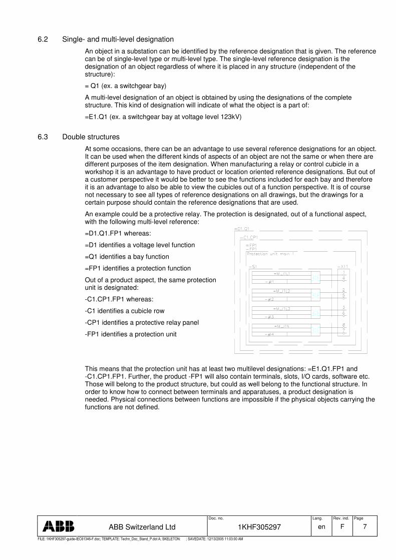
An example could be a protective relay. The protection is designated, out of a functional aspect, with the following multi-level reference:
=D1.Q1.FP1 whereas:
=D1 identifies a voltage level function
=Q1 identifies a bay function
=FP1 identifies a protection function
Out of a product aspect, the same protection unit is designated:
-C1.CP1.FP1 whereas:
-C1 identifies a cubicle row
-CP1 identifies a protective relay panel
-FP1 identifies a protection unit
This means that the protection unit has at least two multilevel designations: =E1.Q1.FP1 and -C1.CP1.FP1. Further, the product -FP1 will also contain terminals, slots, I/O cards, software etc. Those will belong to the product structure, but could as well belong to the functional structure. In order to know how to connect between terminals and apparatuses, a product designation is needed. Physical connections between functions are impossible if the physical objects carrying the functions are not defined.

Doc. no. Lang. Rev. ind. Page
ABB Switzerland Ltd 1KHF305297 en F 8
�������� � � � � � �� � �� � ���� � � � � ���� � � ����� � � ������ � ! " # $ � � # % &' " � # � �� � &� ��% � ����( ) ���������% * �$ ����� +� + � � � ����� �� � � � �
6.4 Transition from one aspect structure to an other
It is not always possible, nor suitable, to identify an object in the considered system by one aspect only. Therefore the object can have multiple multi-level reference designations, identifying the position of the object of interest within the different structures. A reason to use different structure may be that different departments or organisations make different parts of a substation, where some parts are handled and produced as products and other parts are documented as co-operating functions. In a typical project management process is the higher level design work function oriented but the detailed engineering is documented in a product oriented way.
Transitions have nothing to do with structuring. It is only a method for achieving unambiguous reference designations utilizing given structures. Transitions are only to be used if necessary and should be omitted if possible.
For example, the integration of predefined solutions into given structures (e.g. primary equipment structure) without the possibility of changing the given structures or of introducing new structures. If e.g. a product-oriented unit (object) will be arranged as a sub-object to an object in a function oriented structure a transition is required from the function-oriented structure to the product oriented structure used in the actual unit. A transition object must be defined in which the transition between the structures (aspects) will be possible.
A method of identification of transition objects in documents is to show both the prefix of the structure (aspect) from which the transition is made and the structure is goes to. The both prefixes are written before the reference designation of the transition object 3. Example: =E1.Q1-QA1, whereas:
=E1 identifies a voltage level function
=Q1 identifies a bay function
=-QA1 identifies the product circuit breaker and its function referring to the function structure
Both types of prefix are used, e.g. =-QA1, in order to indicate that the object –QA1 is a product belonging to a functional structure.
Since the product designation for levels higher then the apparatus itself is of less interest, the product -QA1 will in this case be identified as a sub-object in the functional structure.
The requirement of a transition object is that the object is completely defined as one object in both the structures involved in the transition. E.g. if a transition from function structure to product structure is required then the transition object must be a product that includes the full function of the object in the function structure. The product must not include any other functions, which can be found in other paths of the function structure. It is obvious by this description that the transition object is one and the same object with a function oriented and a product oriented reference designation. The parts of the product (transition object) will be unambiguously designated by the "internal" product structure even if the object itself is identified in the substation by a function oriented reference designation.
In circuit diagram and other documents it could be necessary to specific identify such transition object. A method of identification is to show both the prefix of the structure (aspect) from which the transition is made and the structure is goes to. The both prefixes are written before the reference designation of the transition object 4.
3. The method of using double prefixes to identify a transition object has been established because the feature has not been defined in any IEC standard so far. 4 Transition from structure to structure may be possible even if the object is not defined with double prefixes.
Doc. no. Lang. Rev. ind. Page
ABB Switzerland Ltd 1KHF305297 en F 9
�������� � � � � � �� � �� � ���� � � � � ���� � � ����� � � ������ � ! " # $ � � # % &' " � # � �� � &� ��% � ����( ) ���������% * �$ ����� +� + � � � ����� �� � � � �
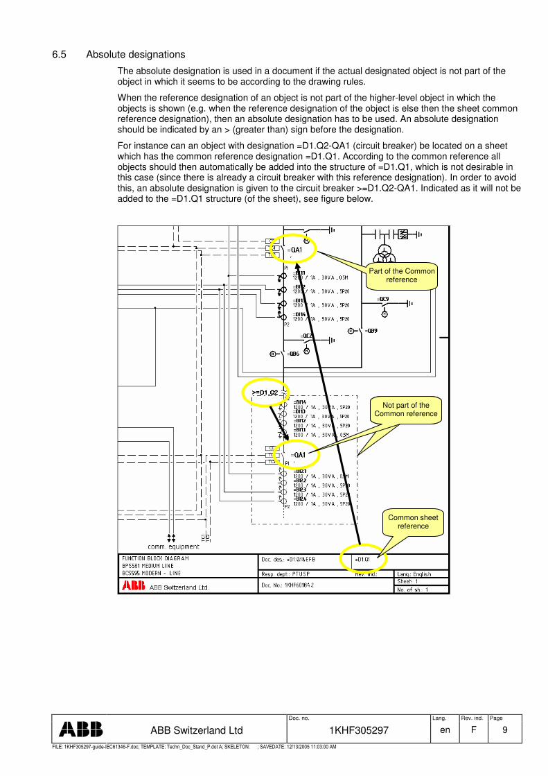
6.5 Absolute designations
The absolute designation is used in a document if the actual designated object is not part of the object in which it seems to be according to the drawing rules.
When the reference designation of an object is not part of the higher-level object in which the objects is shown (e.g. when the reference designation of the object is else then the sheet common reference designation), then an absolute designation has to be used. An absolute designation should be indicated by an > (greater than) sign before the designation.
For instance can an object with designation =D1.Q2-QA1 (circuit breaker) be located on a sheet which has the common reference designation =D1.Q1. According to the common reference all objects should then automatically be added into the structure of =D1.Q1, which is not desirable in this case (since there is already a circuit breaker with this reference designation). In order to avoid this, an absolute designation is given to the circuit breaker >=D1.Q2-QA1. Indicated as it will not be added to the =D1.Q1 structure (of the sheet), see figure below.
Not part of the Common reference
Common sheet reference
Part of the Common reference
Not part of the Common reference
Doc. no. Lang. Rev. ind. Page
ABB Switzerland Ltd 1KHF305297 en F 10
�������� � � � � � �� � �� � ���� � � � � ���� � � ����� � � ������ � ! " # $ � � # % &' " � # � �� � &� ��% � ����( ) ���������% * �$ ����� +� + � � � ����� �� � � � �
7. Structuring principles
7.1 General
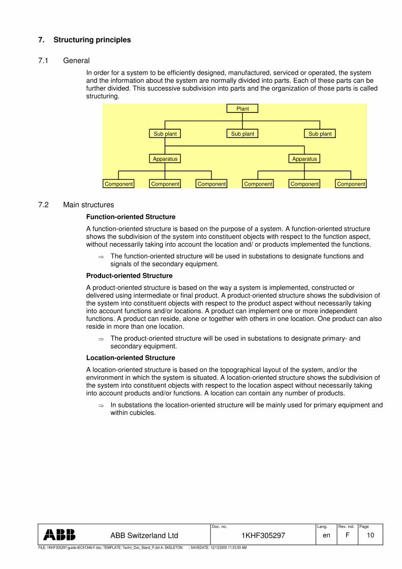
In order for a system to be efficiently designed, manufactured, serviced or operated, the system and the information about the system are normally divided into parts. Each of these parts can be further divided. This successive subdivision into parts and the organization of those parts is called structuring.
Plant
Sub plant Sub plant Sub plant
Apparatus Apparatus
Component Component Component Component Component Component
7.2 Main structures
Function-oriented Structure
A function-oriented structure is based on the purpose of a system. A function-oriented structure shows the subdivision of the system into constituent objects with respect to the function aspect, without necessarily taking into account the location and/ or products implemented the functions.
� The function-oriented structure will be used in substations to designate functions and signals of the secondary equipment.
Product-oriented Structure
A product-oriented structure is based on the way a system is implemented, constructed or delivered using intermediate or final product. A product-oriented structure shows the subdivision of the system into constituent objects with respect to the product aspect without necessarily taking into account functions and/or locations. A product can implement one or more independent functions. A product can reside, alone or together with others in one location. One product can also reside in more than one location.
� The product-oriented structure will be used in substations to designate primary- and secondary equipment.
Location-oriented Structure
A location-oriented structure is based on the topographical layout of the system, and/or the environment in which the system is situated. A location-oriented structure shows the subdivision of the system into constituent objects with respect to the location aspect without necessarily taking into account products and/or functions. A location can contain any number of products.
� In substations the location-oriented structure will be mainly used for primary equipment and within cubicles.
Doc. no. Lang. Rev. ind. Page
ABB Switzerland Ltd 1KHF305297 en F 11
�������� � � � � � �� � �� � ���� � � � � ���� � � ����� � � ������ � ! " # $ � � # % &' " � # � �� � &� ��% � ����( ) ���������% * �$ ����� +� + � � � ����� �� � � � �
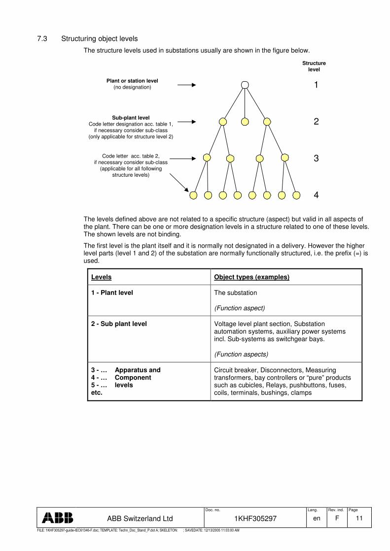
7.3 Structuring object levels
The structure levels used in substations usually are shown in the figure below.
Plant or station level(no designation)
Sub-plant levelCode letter designation acc. table 1,
if necessary consider sub-class(only applicable for structure level 2)
Code letter acc. table 2,if necessary consider sub-class
(applicable for all followingstructure levels)
Structurelevel
2
3
4
1
The levels defined above are not related to a specific structure (aspect) but valid in all aspects of the plant. There can be one or more designation levels in a structure related to one of these levels. The shown levels are not binding.
The first level is the plant itself and it is normally not designated in a delivery. However the higher level parts (level 1 and 2) of the substation are normally functionally structured, i.e. the prefix (=) is used.
Levels Object types (examples)
1 - Plant level The substation
(Function aspect)
2 - Sub plant level Voltage level plant section, Substation automation systems, auxiliary power systems incl. Sub-systems as switchgear bays.
(Function aspects)
3 - … Apparatus and 4 - … Component 5 - … levels etc.
Circuit breaker, Disconnectors, Measuring transformers, bay controllers or “pure” products such as cubicles, Relays, pushbuttons, fuses, coils, terminals, bushings, clamps

Doc. no. Lang. Rev. ind. Page
ABB Switzerland Ltd 1KHF305297 en F 12
�������� � � � � � �� � �� � ���� � � � � ���� � � ����� � � ������ � ! " # $ � � # % &' " � # � �� � &� ��% � ����( ) ���������% * �$ ����� +� + � � � ����� �� � � � �
8. Codes for structuring
8.1 Format of reference designations
A reference designation assigned to an object shall consist of a prefix sign followed either by:
- a letter code, or - a letter code followed by a number code, or - a number code
Prefix = / + / - AAAnn . AAAnn
Prefix: The following prefixes are used in order to distinguish the kind of aspect of designation = Function aspect - Product aspect + Location aspect
AAA Letter code. The letter code may indicate the object or indicate the class of object. Each object can be classified according to table 1 and table 2 and be coded with the associated letter codes. A letter code may consist of any number of letters. In a letter code consisting of multiple letters, the second (third, etc.) letter shall indicate a subclass of the class indicated by the first (second, etc.) letter. Letter codes shall be formed using capital letters A to Z (excluding special national letters). Letters I and O shall not be used if confusion with digits 1 (one) and o (zero) is likely.
nn: Number code. Counting number or predefined number. Numbers may contain leading zeros. If both a letter code and a number are used, then the number shall follow the letter code.
. (dot). For separation between designations when using multi-level reference designations in the same aspect
In order to aid readability it is recommended that numbers and letter codes are kept as short as practicable.
8.2 Reference designation set
It is not always possible, nor suitable, to identify an object in the considered system by one aspect only. Therefore the object can have multiple multi-level reference designations, identifying the position of the object of interest within the different aspect structures.
If these multi-level reference designations need to be indicated for a certain purpose, for example to indicate both the position of the object of interest within the product oriented structure, and where the object if interest is located, a reference designation set shall be provided. For a reference designation set, the following apply:
� At least one reference designation in a set needs to be unambiguous.
� Each reference designation shall be clearly separated from the others.
Example for a reference designation set of a bay control unit (IED):
=D1.Q2 -C1.CC1.A1
+C1.CC1.U.30
The function-oriented reference designation is not unambiguous for the bay control unit because it is assumed that also other equipment (i.e. switchgear) adds to the realization of the task “power feeding on 220kV”. The location oriented reference designation is not unambiguous because the bay control unit is not (or may not) the only assembly in this place. In this case the only unambiguous identifier is the product-oriented reference designation.
Doc. no. Lang. Rev. ind. Page
ABB Switzerland Ltd 1KHF305297 en F 13
�������� � � � � � �� � �� � ���� � � � � ���� � � ����� � � ������ � ! " # $ � � # % &' " � # � �� � &� ��% � ����( ) ���������% * �$ ����� +� + � � � ����� �� � � � �
8.3 Designation of level 1
The first level is the plant itself and it is normally not designated in a delivery.
8.4 Designation of level 2
The normative standard IEC 61346-2 provides a frame for the classification of infrastructure objects.
The classification according to the table 1 (classification of infrastructure objects) will exclusively be used for structure level 2 within a substation.
8.5 Designation of level 3 or lower
The normative standard IEC 61346-2 provides the letter codes for the classification of objects according their purpose or task.
The classification of objects according to table 2 (classification of objects according their purpose or task) will be used for objects of all levels except level 2. Note: A separate code is used for functions running on IEDs and protection functions (table 3).
8.6 Designation of protection functions and functions running on IEDs
The detailed functions running on an intelligent electronic device (including a communication interface) are designated according to IEC 61850-5 and IEC 61850-7-4 (Normative standard for communication networks and systems in substations). All other protection functions are designated by numbers, with appropriate suffix letters (when necessary) according to extract from IEEE C37.2-1996(R2001).
According to IEC61850 functions are tasks, which are performed by the substation automation system. A logical node (LN) is the smallest part of a function that exchanges data. A LN represents the function within a physical device; it performs some operations for that function. A LN is an object defined by its data and methods. Logical nodes related to primary equipment are not the primary equipment itself but its intelligent part or image in the secondary system, i.e. local or remote I/Os, intelligent sensors and actuators, etc.

Doc. no. Lang. Rev. ind. Page
ABB Switzerland Ltd 1KHF305297 en F 14
�������� � � � � � �� � �� � ���� � � � � ���� � � ����� � � ������ � ! " # $ � � # % &' " � # � �� � &� ��% � ����( ) ���������% * �$ ����� +� + � � � ����� �� � � � �
9. Reference designation rules for secondary equipment in substations
Object reference designations are mainly used for apparatus or units with electrical functions. The reference designations are function, product or location oriented. All types are built up of levels in a structural way. One or several of the three types of designations may be used to identify an item.
The planning of a substation starts with a functional design.
� The function-oriented reference designation allows a systematic storage of information on a process task without knowing how the task described will be achieved. It will be decided in a later stage of the engineering process which equipment is to be used for the implementation. Information on this equipment may be referenced with the help of product-oriented reference designations.
� The relationship between the product-oriented reference designation and the function-oriented reference designation is kept in the database and supplemented with a location-oriented reference designation. Later, it will be easy to obtain which products are involved in the realisation of a specific process task and where they are located from the database. It is also possible to evaluate which different tasks are realized by a specific product.
The user has to decide which type of aspect is relevant:
� The base design will probably start with the definition of the objects that are based on process tasks. It is necessary to at least provide information on the process task itself and on the constituent tasks. In addition, information may be provided on equipment intended to realize the process task and also on the foreseen location.
� An experienced planning engineer will probably start with the definition of the objects based on equipment, as he already knows the technical solution.
9.1 Functional designations
The functional structure is useful to describe the purpose or tasks to be performed in a substation, without necessarily taking in account the location and/or the products implementing the function. It is used in an early planning phase of the substation. Functional references designations for substations are mainly used for the primary process objects.
The substation is normally broken down into a functional structure based on transmission and/or distribution systems with different voltage levels. The transmission and distribution switchgear assemblies are divided into busbars and bays (feeders).The first level in the structure is the plant itself, which is not designated. The objects in the second level can be voltage level units, common plant systems, transforming bays, switchgear bays and busbars. The bay function can consist of one or several switching devices and are then defined as power switching functions. Those without switching devices, but still are carrying energy, are defined as busbars. Usually are only the function designations used at this level, although products and locations also do exist as aspects. But the later ones are not used.
For the secondary equipment the functional designation is used to designate functions and signals unambiguous.
Functional reference designation example for a 150kV busbar 2 disconnector of power feeder 3:
=E1.Q3.QB2

Doc. no. Lang. Rev. ind. Page
ABB Switzerland Ltd 1KHF305297 en F 15
�������� � � � � � �� � �� � ���� � � � � ���� � � ����� � � ������ � ! " # $ � � # % &' " � # � �� � &� ��% � ����( ) ���������% * �$ ����� +� + � � � ����� �� � � � �
9.2 Product designations
A product-oriented structure is based on the way a system is implemented, constructed or delivered using intermediate or final products. Products usually are the things that can be seen, like apparatuses and components, but also software. The product reference designation needs to be unambiguous in a reference designation set for designating a product. A product can implement one or more independent functions. A product can reside, alone or together with others in one location. One product can also reside in more than one location. A product does often have an article number or serial number and can be an individual.
For the secondary equipment a cubicle shall be designated as an independent product. The equipment built in the cubicle are designated as sub products of the cubicle.
If a cubicle holds equipment for controlling (or protecting) for more than only one power feeder then the product “cubicle” implements more than one independent function. The equipment used for controlling (or protecting) of each power feeder will be treated as modules within the cubicle. The modules are treated as sub-products of the product “cubicle”. This modules can be identified either by a counting number or by the power feeder name to which the module it belongs to.
For the secondary equipment the product designation is used to designate the products unambiguous.
Product reference designation example for a main 1 protection relay as part of the 2nd protection panel of the 1st cubicle row:
-C1.CP2.FP1
9.3 Location designations
Location reference designations should be seen as a positioning system by using a co-ordinate system or similar. The switchyard area can be defined in co-ordinates as well as the houses included in plant and further on the rooms. The location designation can also be a reference to another product, which has a pre-defined location.
For the secondary equipment in a substation, the location structure is mostly used in the relay and control cubicles, where the control devices, relays and protective relays can be located by the means of their reference designation. I.e. the reference designation will be a guide to the objects position.
Doc. no. Lang. Rev. ind. Page
ABB Switzerland Ltd 1KHF305297 en F 16
�������� � � � � � �� � �� � ���� � � � � ���� � � ����� � � ������ � ! " # $ � � # % &' " � # � �� � &� ��% � ����( ) ���������% * �$ ����� +� + � � � ����� �� � � � �
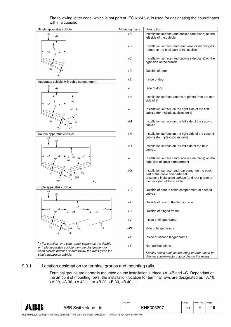
The following letter code, which is not part of IEC 61346-2, is used for designating the co-ordinates within a cubicle:
Single apparatus cubicle: Mounting plane Description
+U
+V
+E
+D
+K+H
+B+A +C
Apparatus cubicle with cable compartment:
+U
+V
+E
+D
+K+H
+B+A +C
+S
+Q
+J
+F
+W
Double apparatus cubicle:
+U
+V
+E
+D
+K+H
+B+A +C+L +M
+U2
+V2
+D2
+A
+F
+W
*) Triple apparatus cubicle:
+U
+V
+E
+D
+K+H
+B+A +N
+S
+C
+T
+L+M +O
+F
+W
*) If a partition- or a side- panel separates the double or triple apparatus cubicle then the designation for each cubicle partition should follow the rules given for single apparatus cubicle.
+A
+B
+C
+D
+E
+F
+H
+L
+M
+N
+O
+J
+Q
+S
+T
+U
+V
+W
+X
+Y
Installation surface (and cubicle side plane) on the left side of the cubicle Installation surface (and rear plane or rear hinged frame) on the back part of the cubicle Installation surface (and cubicle side plane) on the right side of the cubicle Outside of door Inside of door Side of door Installation surface (and extra plane) from the rear side of B Installation surface on the right side of the first cubicle (for multiple cubicles only) Installation surface on the left side of the second cubicle Installation surface on the right side of the second cubicle (for triple cubicles only) Installation surface on the left side of the third cubicle. Installation surface (and cubicle side plane) on the right side of cable compartment Installation surface (and rear plane) on the back part of the cable compartment or second installation surface (and rear plane) on the back part of the cubicle Outside of door in cable compartment or second cubicle Outside of door of the third cubicle Outside of hinged frame Inside of hinged frame Side of hinged frame Inside of second hinged frame Non-defined plane
Special cases such as mounting on roof has to be defined supplementary according to the needs.
9.3.1 Location designation for terminal groups and mounting rails
Terminal groups are normally mounted on the installation surface +A, +B and +C. Dependant on the amount of mounting rows, the installation location for terminal rows are designated as +A.10, +A.20, +A.30, +A.40, … or +B.20, +B.30, +B.40, …
Doc. no. Lang. Rev. ind. Page
ABB Switzerland Ltd 1KHF305297 en F 17
�������� � � � � � �� � �� � ���� � � � � ���� � � ����� � � ������ � ! " # $ � � # % &' " � # � �� � &� ��% � ����( ) ���������% * �$ ����� +� + � � � ����� �� � � � �
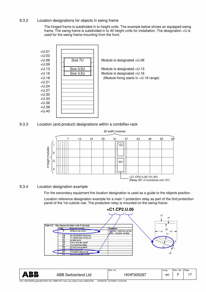
9.3.2 Location designations for objects in swing frame
The hinged frame is subdivided in to height units. The example below shows an equipped swing frame. The swing frame is subdivided in to 40 height units for installation. The designation +U is used for the swing frame-mounting from the front.
+U.01 +U.03 +U.06 Size 7U Module is designated +U.06 +U.09 +U.13 Size 3,5U Module is designated +U.13 +U.16 Size 3,5U Module is designated +U.16 +U.18 (Module-fixing starts in +U.16 range) +U.21 +U.24 +U.27 +U.30 +U.33 +U.36 +U.38 +U.40
9.3.3 Location (and product) designations within a combiflex-rack
101
301
4 he
ight
mod
ules
9.3.4 Location designation example
For the secondary equipment the location designation is used as a guide to the objects position.
Location reference designation example for a main 1 protection relay as part of the 2nd protection panel of the 1st cubicle row. The protection relay is mounted on the swing-frame:
+C1.CP2.U.06
+U
+V
+E
+D
+K+H
+B+A +C
1 7 13 19 25 31 37 43 49 55 60
60 width modules
1
2
3
4
+C1.CP2.U.30.131.301 (Relay 301 in functional unit 131)
Doc. no. Lang. Rev. ind. Page
ABB Switzerland Ltd 1KHF305297 en F 18
�������� � � � � � �� � �� � ���� � � � � ���� � � ����� � � ������ � ! " # $ � � # % &' " � # � �� � &� ��% � ����( ) ���������% * �$ ����� +� + � � � ����� �� � � � �
10. Reference designation examples for secondary equipment in substations
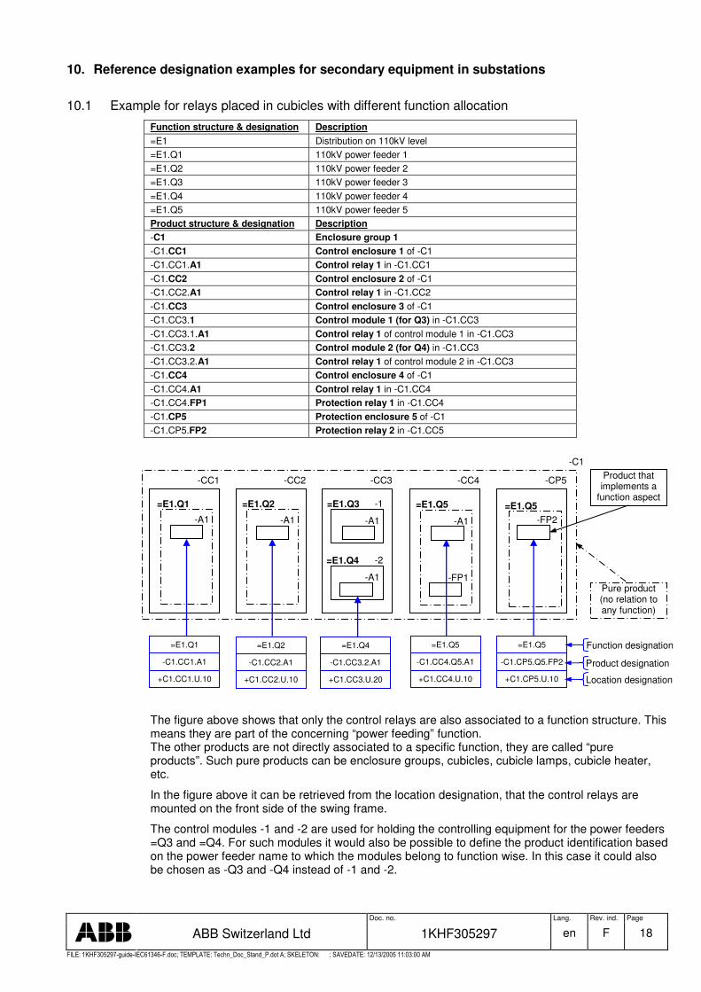
10.1 Example for relays placed in cubicles with different function allocation
Function structure & designation Description =E1 Distribution on 110kV level =E1.Q1 110kV power feeder 1 =E1.Q2 110kV power feeder 2 =E1.Q3 110kV power feeder 3 =E1.Q4 110kV power feeder 4 =E1.Q5 110kV power feeder 5 Product structure & designation Description -C1 Enclosure group 1 -C1.CC1 Control enclosure 1 of -C1 -C1.CC1.A1 Control relay 1 in -C1.CC1 -C1.CC2 Control enclosure 2 of -C1 -C1.CC2.A1 Control relay 1 in -C1.CC2 -C1.CC3 Control enclosure 3 of -C1 -C1.CC3.1 Control module 1 (for Q3) in -C1.CC3 -C1.CC3.1.A1 Control relay 1 of control module 1 in -C1.CC3 -C1.CC3.2 Control module 2 (for Q4) in -C1.CC3 -C1.CC3.2.A1 Control relay 1 of control module 2 in -C1.CC3 -C1.CC4 Control enclosure 4 of -C1 -C1.CC4.A1 Control relay 1 in -C1.CC4 -C1.CC4.FP1 Protection relay 1 in -C1.CC4 -C1.CP5 Protection enclosure 5 of -C1 -C1.CP5.FP2 Protection relay 2 in -C1.CC5
The figure above shows that only the control relays are also associated to a function structure. This means they are part of the concerning “power feeding” function. The other products are not directly associated to a specific function, they are called “pure products”. Such pure products can be enclosure groups, cubicles, cubicle lamps, cubicle heater, etc.
In the figure above it can be retrieved from the location designation, that the control relays are mounted on the front side of the swing frame.
The control modules -1 and -2 are used for holding the controlling equipment for the power feeders =Q3 and =Q4. For such modules it would also be possible to define the product identification based on the power feeder name to which the modules belong to function wise. In this case it could also be chosen as -Q3 and -Q4 instead of -1 and -2.
=E1.Q2 =E1.Q1
-CC1
-A1
-CC2 -CC3
-1
-2
-A1
-A1
-CC4 -CP5
-C1
=E1.Q1
-C1.CC1.A1
=E1.Q5
-C1.CC4.Q5.A1
=E1.Q5
-C1.CP5.Q5.FP2 Product designation
Product that implements a
function aspect
Pure product (no relation to any function)
+C1.CC1.U.10
=E1.Q2
-C1.CC2.A1
+C1.CC2.U.10
=E1.Q4
-C1.CC3.2.A1
+C1.CC3.U.20 +C1.CC4.U.10 +C1.CP5.U.10
Function designation
Location designation
-A1 =E1.Q5
-FP2
=E1.Q3
=E1.Q4
-A1
-FP1
=E1.Q5

Doc. no. Lang. Rev. ind. Page
ABB Switzerland Ltd 1KHF305297 en F 19
�������� � � � � � �� � �� � ���� � � � � ���� � � ����� � � ������ � ! " # $ � � # % &' " � # � �� � &� ��% � ����( ) ���������% * �$ ����� +� + � � � ����� �� � � � �
10.2 Structuring example for one BCS in one cubicle
The following table shows a structuring example for a bay control solutions which is built in one cubicle. Note: Wavy line indicates that the function structure is not applicable for the shown product.
Function structure Product structure Location structure =E1 Voltage level function 110kV
=Q2 Power feeder function -C1 Enclosure group (cubicle row 1) +C1 -CC2 Control cubicle no.2 +CC2 -F11 DC1 MCB 1 +U0 -X11 DC1 distribution terminal group 1 +V0 -A1 Bay control unit (IED) +U21 -A2 Bay control mimic +U09 -S10 Control mode switch -S20 Interlock by-pass switch -P1 Measuring device -QA1 Circuit breaker control module -K1 SF6 block trip 1 relay +B20 -K2 SF6 block trip 2 relay +B20 -1 Phase L1 control -X1 Process interface 1 +B40 -X2 Process interface 2 +B40 -QB1 Busbar 1 disconnector control module -X1 Process interface 1 +B60 -X2 Process interface 2 +B50
10.3 Structuring example for two BCS in one cubicle
The following table shows a structuring example for two bay control solutions that are built in one cubicle. The product structure in the table below is structured as similar as possible according to the function structure. The reason is that the product is built on modules that are designed to serve or to support a primary process function. An advantage is that unique designations are only needed within the modules. If it is not convenient for the cubicle designer to use the modules (functional split) within the product structure then the modules can be omitted from the product structure.
Note: Wavy line indicates that the function structure is not applicable for the shown product.
Function structure Product structure Location structure =E1 Voltage level function 110kV
-C1 Enclosure group (cubicle row 1) +C1 -CC3 Control cubicle no.2 +CC3 -F11 DC1 MCB 1 +U0 -X11 DC1 distribution terminal group 1 +V0 =Q3 Power feeder function 3 -1 Power feeder control module 1 -A1 Bay control unit (IED) +U11 -QA1 Circuit breaker control module -K1 SF6 block trip 1 relay +B10 -K2 SF6 block trip 2 relay +B10 -1 -X1 Process interface 1 +B20 -X2 Process interface 2 +B20 -QB1 Busbar 1 disconnector control module -X1 Process interface 1 +B20 -X2 Process interface 2 +B20 =Q4 Power feeder function 4 -2 Power feeder control module 2 -A1 Bay control unit (IED) +U22 -QA1 Circuit breaker control module -K1 SF6 block trip 1 relay +B30 -K2 SF6 block trip 2 relay +B30 -1 -X1 Process interface 1 +B40 -X2 Process interface 2 +B40 -QB1 Busbar 1 disconnector control module -X1 Process interface 1 +B40 -X2 Process interface 2 +B40
The reference designation set of this selected product is:
=E1.Q4 -C1.CC3.2.QA1.K2
+C1.CC3.B.30
Doc. no. Lang. Rev. ind. Page
ABB Switzerland Ltd 1KHF305297 en F 20
�������� � � � � � �� � �� � ���� � � � � ���� � � ����� � � ������ � ! " # $ � � # % &' " � # � �� � &� ��% � ����( ) ���������% * �$ ����� +� + � � � ����� �� � � � �
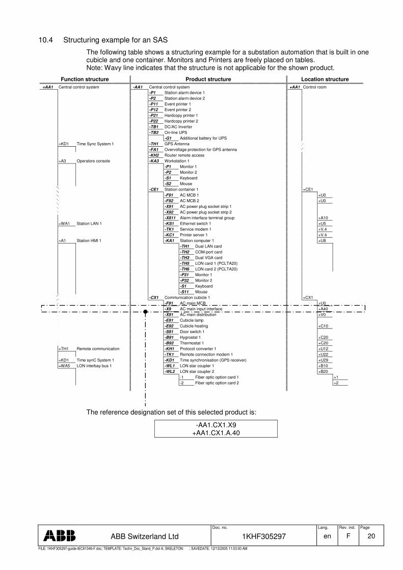
10.4 Structuring example for an SAS
The following table shows a structuring example for a substation automation that is built in one cubicle and one container. Monitors and Printers are freely placed on tables. Note: Wavy line indicates that the structure is not applicable for the shown product.
Function structure Product structure Location structure =AA1 Central control system -AA1 Central control system +AA1 Control room
-P1 Station alarm device 1 -P2 Station alarm device 2 -P11 Event printer 1 -P12 Event printer 2 -P21 Hardcopy printer 1 -P22 Hardcopy printer 2 -TB1 DC/AC Inverter -TB2 On-line UPS -G1 Additional battery for UPS =KD1 Time Sync System 1 -TH1 GPS Antenna -FA1 Overvoltage protection for GPS antenna -KH2 Router remote access =A3 Operators console -KA3 Workstation 1 -P1 Monitor 1 -P2 Monitor 2 -S1 Keyboard -S2 Mouse -CE1 Station container 1 +CE1 -F91 AC MCB 1 +U0 -F92 AC MCB 2 +U0 -X91 AC power plug socket strip 1 -X92 AC power plug socket strip 2 -X811 Alarm interface terminal group +A10 =WA1 Station LAN 1 -KS1 Ethernet switch 1 +U5 -TK1 Service modem 1 +V.4 -KC1 Printer server 1 +V.4 =A1 Station HMI 1 -KA1 Station computer 1 +U8 -TH1 Dual LAN card -TH2 COM-port card -TH3 Dual VGA card -TH5 LON card 1 (PCLTA20) -TH6 LON card 2 (PCLTA20) -P31 Monitor 1 -P32 Monitor 2 -S1 Keyboard -S11 Mouse -CX1 Communication cubicle 1 +CX1 -F91 AC main MCB +U0 -X9 AC main input interface +A40 -X91 AC main distribution +V0 -E91 Cubicle lamp -E92 Cubicle heating +C10 -S91 Door switch 1 -B91 Hygrostat 1 +C20 -B92 Thermostat 1 +C20 =TH1 Remote communication -KH1 Protocol converter 1 +U12 -TK1 Remote connection modem 1 +U22 =KD1 Time synC System 1 -KD1 Time synchronisation (GPS receiver) +U29 =WA5 LON interbay bus 1 -WL1 LON star coupler 1 +B10 -WL2 LON star coupler 2 +B20 -1 Fiber optic option card 1 +1 -2 Fiber optic option card 2 +2
The reference designation set of this selected product is:
-AA1.CX1.X9 +AA1.CX1.A.40

Doc. no. Lang. Rev. ind. Page
ABB Switzerland Ltd 1KHF305297 en F 21
�������� � � � � � �� � �� � ���� � � � � ���� � � ����� � � ������ � ! " # $ � � # % &' " � # � �� � &� ��% � ����( ) ���������% * �$ ����� +� + � � � ����� �� � � � �
10.5 Function designation examples for HV equipment
The following figures show the functional item designations for some typical bays. The used designations are based on table 4 of this document. Example for typical double busbar bays:
=QB1 =QB2
=QA1
=QB9
=QC1
=QC2
=QC9
Line feeder
=BI1
=BI2
=BU1
=Q1
=WA1
=WA2
Busbar 1
Busbar 2
=QB1 =QB2
=QA1
=QC1
=QC2
Transformer feeder
=BI1
=Q1
=WA1
=WA2
Busbar 1
Busbar 2
=T1
=BI1
=BI2
=T1
=N1
=BI3
=QB1 =QB2
Bus coupler
=Q1
=WA1
=WA2
Busbar 1
Busbar 2
=QA1
=QC1 =QC2
=BI1
Bus section
=QB1 =QB2
=Q2
=WA2.1
=QA1
=QC1
=QC2
=BI1
=QC22
=BU22
=QC21
=BU21
=QC11
=BU11
=QC12
=BU12
=QB1
=WA1.1=WA2.2=WA1.2
=Q1

Doc. no. Lang. Rev. ind. Page
ABB Switzerland Ltd 1KHF305297 en F 22
�������� � � � � � �� � �� � ���� � � � � ���� � � ����� � � ������ � ! " # $ � � # % &' " � # � �� � &� ��% � ����( ) ���������% * �$ ����� +� + � � � ����� �� � � � �
Example for 1 ½- breaker system
=QA1
=QA1
=QA1
=QB1
=QC1
=QB6
=QB9
=QC9
=QC3
=QC2
=QB61
=QB62
=QC1
=QC2
=QB9
=QC9
=QC3
=QC2
=QC1
=QB6
=QB2
1 1/2 - Breaker system
=Q3
=Q2
=Q1
Busbar 1
Busbar 2

Doc. no. Lang. Rev. ind. Page
ABB Switzerland Ltd 1KHF305297 en F 23
�������� � � � � � �� � �� � ���� � � � � ���� � � ����� � � ������ � ! " # $ � � # % &' " � # � �� � &� ��% � ����( ) ���������% * �$ ����� +� + � � � ����� �� � � � �
10.6 Function designation example for a function block diagram
comm. equipment comm. equipment
-C1.CP1
Rem
ote
Trip
���������������������� ����� ���
������� �
������� �
�
����������������
� ����������������
�
����������������
������ ����� ����� ����� �������������� ��
����������������
�����������������
�����������������
�
����������������
���� ����� ����� ����� �����������������
���� ����� ����� ����� �����������������
��
���� ����� ����� ����� �����������������
TC1
TC2
CC
Busbar 1
Busbar 2
=PBDFU187B
=RBRFU151BF
=PTRCTRIP
=PTOCU151EFP
TCTRNCT
TCTRL3CT
TCTRL2CT
=TCTRL1CT
=RPSB168
=PPBV147VTS
=PDEF167N
=RDRE195DR
=TVTRU1VT
=TVTRU2VT
=PSCHZ<21
=RFLO121FL
=PTOV159
=PTOC151
=PSCHEF67N
=PTRCTRIP
TCTRL3CT
TCTRL2CT
=TCTRL1CT
TVTRL3VT
TVTRL2VT
=TVTRL1VT
PDISZ521
PDISZ421
PDISZ321
PDISZ221
=PDISZ121
=RPSB168
=PPBV147VTS
=PDEF167N
=RDRE195DR
=PSCHZ<21
=RFLO121FL
=PTOV159
=PTOC151
=PSCHEF67N
=PTRCTRIP
PDISZ521
PDISZ421
PDISZ321
PDISZ221
=PDISZ121
TCTRNCT
TCTRL3CT
TCTRL2CT
=TCTRL1CT
TVTRL3VT
TVTRL2VT
=TVTRL1VT
=RDRE195DR
=27TCS27
=27TCS27
Opt
ical
Inte
face
-C1.CP1.FP1
-C1.CP1.FP3
LD1 / LON Main 1 protection unit
LD1 / LON Station bay protection unit
-C1.CP1.FP2LD1 / LON Main 2 protection unit
The functions shown in the function block diagram are designated according to table 3 of this document. Functions running on a IED are designated according to IEC 61850 (e.g. =PTOC). Others are designated according to IEEE Std C37.2-1996 (e.g. =27).
Doc. no. Lang. Rev. ind. Page
ABB Switzerland Ltd 1KHF305297 en F 24
�������� � � � � � �� � �� � ���� � � � � ���� � � ����� � � ������ � ! " # $ � � # % &' " � # � �� � &� ��% � ����( ) ���������% * �$ ����� +� + � � � ����� �� � � � �
11. Code tables
11.1 Letter codes for infrastructure objects
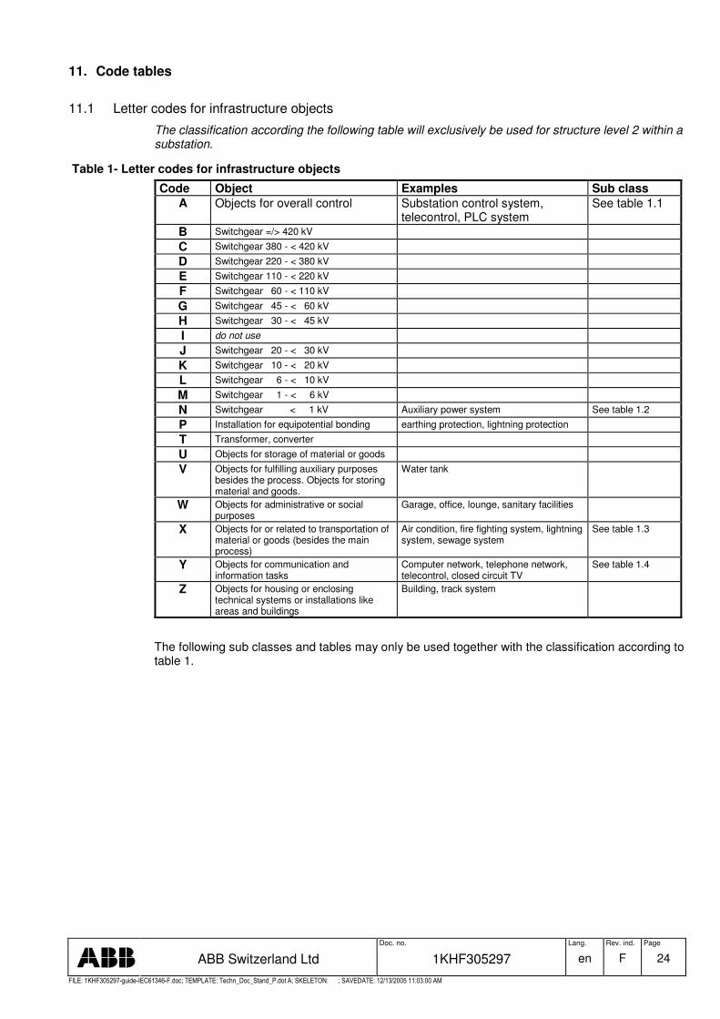
The classification according the following table will exclusively be used for structure level 2 within a substation.
Table 1- Letter codes for infrastructure objects
Code Object Examples Sub class A Objects for overall control Substation control system,
telecontrol, PLC system See table 1.1
B Switchgear =/> 420 kV
C Switchgear 380 - < 420 kV
D Switchgear 220 - < 380 kV
E Switchgear 110 - < 220 kV
F Switchgear 60 - < 110 kV
G Switchgear 45 - < 60 kV
H Switchgear 30 - < 45 kV
I do not use
J Switchgear 20 - < 30 kV
K Switchgear 10 - < 20 kV
L Switchgear 6 - < 10 kV
M Switchgear 1 - < 6 kV
N Switchgear < 1 kV Auxiliary power system See table 1.2
P Installation for equipotential bonding earthing protection, lightning protection
T Transformer, converter
U Objects for storage of material or goods
V Objects for fulfilling auxiliary purposes besides the process. Objects for storing material and goods.
Water tank
W Objects for administrative or social purposes
Garage, office, lounge, sanitary facilities
X Objects for or related to transportation of material or goods (besides the main process)
Air condition, fire fighting system, lightning system, sewage system
See table 1.3
Y Objects for communication and information tasks
Computer network, telephone network, telecontrol, closed circuit TV
See table 1.4
Z Objects for housing or enclosing technical systems or installations like areas and buildings
Building, track system
The following sub classes and tables may only be used together with the classification according to table 1.
Doc. no. Lang. Rev. ind. Page
ABB Switzerland Ltd 1KHF305297 en F 25
�������� � � � � � �� � �� � ���� � � � � ���� � � ����� � � ������ � ! " # $ � � # % &' " � # � �� � &� ��% � ����( ) ���������% * �$ ����� +� + � � � ����� �� � � � �
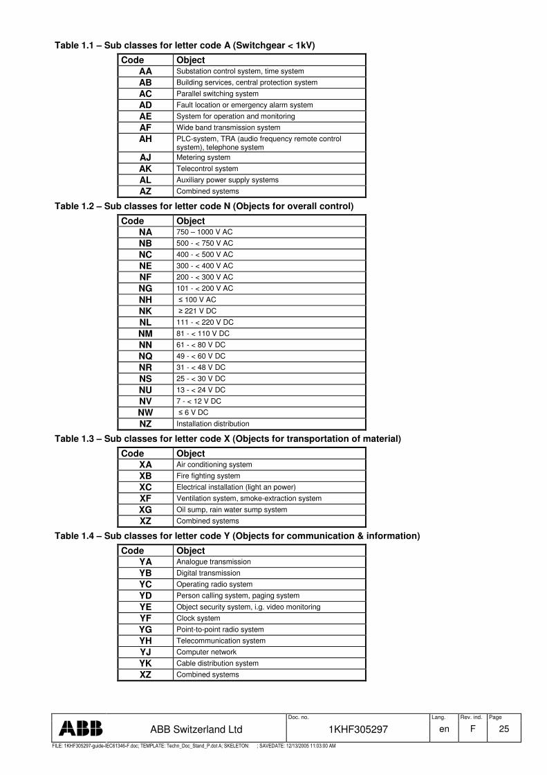
Table 1.1 – Sub classes for letter code A (Switchgear < 1kV)
Code Object AA Substation control system, time system
AB Building services, central protection system
AC Parallel switching system
AD Fault location or emergency alarm system
AE System for operation and monitoring
AF Wide band transmission system
AH PLC-system, TRA (audio frequency remote control system), telephone system
AJ Metering system
AK Telecontrol system
AL Auxiliary power supply systems
AZ Combined systems
Table 1.2 – Sub classes for letter code N (Objects for overall control)
Code Object NA 750 – 1000 V AC
NB 500 - < 750 V AC
NC 400 - < 500 V AC
NE 300 - < 400 V AC
NF 200 - < 300 V AC
NG 101 - < 200 V AC
NH � 100 V AC
NK � 221 V DC
NL 111 - < 220 V DC
NM 81 - < 110 V DC
NN 61 - < 80 V DC
NQ 49 - < 60 V DC
NR 31 - < 48 V DC
NS 25 - < 30 V DC
NU 13 - < 24 V DC
NV 7 - < 12 V DC
NW � 6 V DC
NZ Installation distribution
Table 1.3 – Sub classes for letter code X (Objects for transportation of material)
Code Object XA Air conditioning system
XB Fire fighting system
XC Electrical installation (light an power)
XF Ventilation system, smoke-extraction system
XG Oil sump, rain water sump system
XZ Combined systems
Table 1.4 – Sub classes for letter code Y (Objects for communication & information)
Code Object YA Analogue transmission
YB Digital transmission
YC Operating radio system
YD Person calling system, paging system
YE Object security system, i.g. video monitoring
YF Clock system
YG Point-to-point radio system
YH Telecommunication system
YJ Computer network
YK Cable distribution system
XZ Combined systems
Doc. no. Lang. Rev. ind. Page
ABB Switzerland Ltd 1KHF305297 en F 26
�������� � � � � � �� � �� � ���� � � � � ���� � � ����� � � ������ � ! " # $ � � # % &' " � # � �� � &� ��% � ����( ) ���������% * �$ ����� +� + � � � ����� �� � � � �
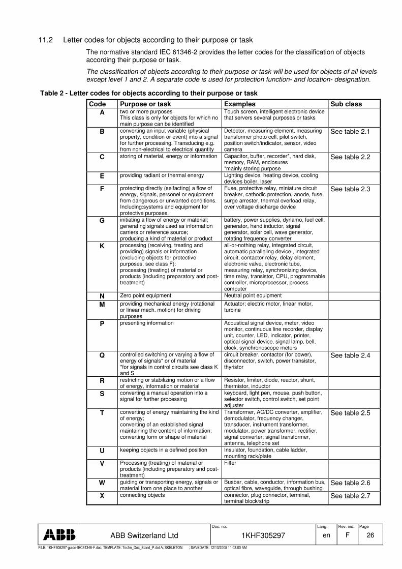
11.2 Letter codes for objects according to their purpose or task
The normative standard IEC 61346-2 provides the letter codes for the classification of objects according their purpose or task.
The classification of objects according to their purpose or task will be used for objects of all levels except level 1 and 2. A separate code is used for protection function- and location- designation.
Table 2 - Letter codes for objects according to their purpose or task
Code Purpose or task Examples Sub class A two or more purposes
This class is only for objects for which no main purpose can be identified
Touch screen, intelligent electronic device that servers several purposes or tasks
B converting an input variable (physical property, condition or event) into a signal for further processing. Transducing e.g. from non-electrical to electrical quantity
Detector, measuring element, measuring transformer photo cell, pilot switch, position switch/indicator, sensor, video camera
See table 2.1
C storing of material, energy or information Capacitor, buffer, recorder*, hard disk, memory, RAM, enclosures *mainly storing purpose
See table 2.2
E providing radiant or thermal energy Lighting device, heating device, cooling devices boiler, laser
F protecting directly (selfacting) a flow of energy, signals, personel or equipment from dangerous or unwanted conditions. Including:systems and equipment for protective purposes.
Fuse, protective relay, miniature circuit breaker, cathodic protection, anode, fuse, surge arrester, thermal overload relay, over voltage discharge device
See table 2.3
G initiating a flow of energy or material; generating signals used as information carriers or reference source; producing a kind of material or product
battery, power supplies, dynamo, fuel cell, generator, hand inductor, signal generator, solar cell, wave generator, rotating frequency converter
K processing (receiving, treating and providing) signals or information (excluding objects for protective purposes, see class F): processing (treating) of material or products (including preparatory and post-treatment)
all-or-nothing relay, integrated circuit, automatic paralleling device , integrated circuit, contactor relay, delay element, electronic valve, electronic tube, measuring relay, synchronizing device, time relay, transistor, CPU, programmable controller, microprocessor, process computer
N Zero point equipment Neutral point equipment M providing mechanical energy (rotational
or linear mech. motion) for driving purposes
Actuator; electric motor, linear motor, turbine
P presenting information Acoustical signal device, meter, video monitor, continuous line recorder, display unit, counter, LED, indicator, printer, optical signal device, signal lamp, bell, clock, synchronoscope meters
Q controlled switching or varying a flow of energy of signals* or of material *for signals in control circuits see class K and S
circuit breaker, contactor (for power), disconnector, switch, power transistor, thyristor
See table 2.4
R restricting or stabilizing motion or a flow of energy, information or material
Resistor, limiter, diode, reactor, shunt, thermistor, inductor
S converting a manual operation into a signal for further processing
keyboard, light pen, mouse, push button, selector switch, control switch, set point adjuster
T converting of energy maintaining the kind of energy; converting of an established signal maintaining the content of information; converting form or shape of material
Transformer, AC/DC converter, amplifier, demodulator, frequency changer, transducer, instrument transformer, modulator, power transformer, rectifier, signal converter, signal transformer, antenna, telephone set
See table 2.5
U keeping objects in a defined position Insulator, foundation, cable ladder, mounting rack/plate
V Processing (treating) of material or products (including preparatory and post-treatment)
Filter
W guiding or transporting energy, signals or material from one place to another
Busbar, cable, conductor, information bus, optical fibre, waveguide, through bushing
See table 2.6
X connecting objects connector, plug connector, terminal, terminal block/strip
See table 2.7
Doc. no. Lang. Rev. ind. Page
ABB Switzerland Ltd 1KHF305297 en F 27
�������� � � � � � �� � �� � ���� � � � � ���� � � ����� � � ������ � ! " # $ � � # % &' " � # � �� � &� ��% � ����( ) ���������% * �$ ����� +� + � � � ����� �� � � � �
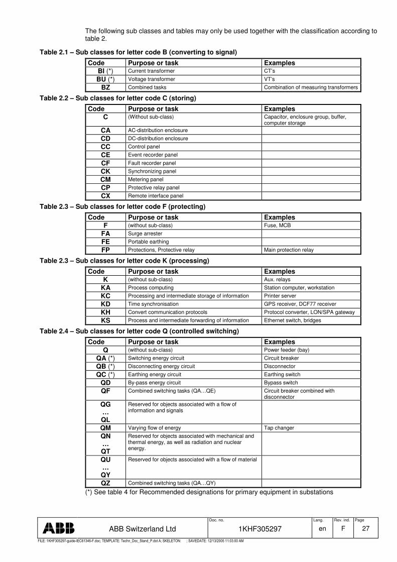
The following sub classes and tables may only be used together with the classification according to table 2.
Table 2.1 – Sub classes for letter code B (converting to signal)
Code Purpose or task Examples BI (*) Current transformer CT’s
BU (*) Voltage transformer VT’s
BZ Combined tasks Combination of measuring transformers
Table 2.2 – Sub classes for letter code C (storing)
Code Purpose or task Examples C (Without sub-class) Capacitor, enclosure group, buffer,
computer storage CA AC-distribution enclosure
CD DC-distribution enclosure
CC Control panel
CE Event recorder panel
CF Fault recorder panel
CK Synchronizing panel
CM Metering panel
CP Protective relay panel
CX Remote interface panel
Table 2.3 – Sub classes for letter code F (protecting)
Code Purpose or task Examples F (without sub-class) Fuse, MCB
FA Surge arrester
FE Portable earthing
FP Protections, Protective relay Main protection relay
Table 2.3 – Sub classes for letter code K (processing)
Code Purpose or task Examples K (without sub-class) Aux. relays
KA Process computing Station computer, workstation
KC Processing and intermediate storage of information Printer server
KD Time synchronisation GPS receiver, DCF77 receiver
KH Convert communication protocols Protocol converter, LON/SPA gateway
KS Process and intermediate forwarding of information Ethernet switch, bridges
Table 2.4 – Sub classes for letter code Q (controlled switching)
Code Purpose or task Examples Q (without sub-class) Power feeder (bay)
QA (*) Switching energy circuit Circuit breaker
QB (*) Disconnecting energy circuit Disconnector
QC (*) Earthing energy circuit Earthing switch
QD By-pass energy circuit Bypass switch
QF Combined switching tasks (QA…QE) Circuit breaker combined with disconnector
QG … QL
Reserved for objects associated with a flow of information and signals
QM Varying flow of energy Tap changer
QN … QT
Reserved for objects associated with mechanical and thermal energy, as well as radiation and nuclear energy.
QU … QY
Reserved for objects associated with a flow of material
QZ Combined switching tasks (QA…QY)
(*) See table 4 for Recommended designations for primary equipment in substations
Doc. no. Lang. Rev. ind. Page
ABB Switzerland Ltd 1KHF305297 en F 28
�������� � � � � � �� � �� � ���� � � � � ���� � � ����� � � ������ � ! " # $ � � # % &' " � # � �� � &� ��% � ����( ) ���������% * �$ ����� +� + � � � ����� �� � � � �
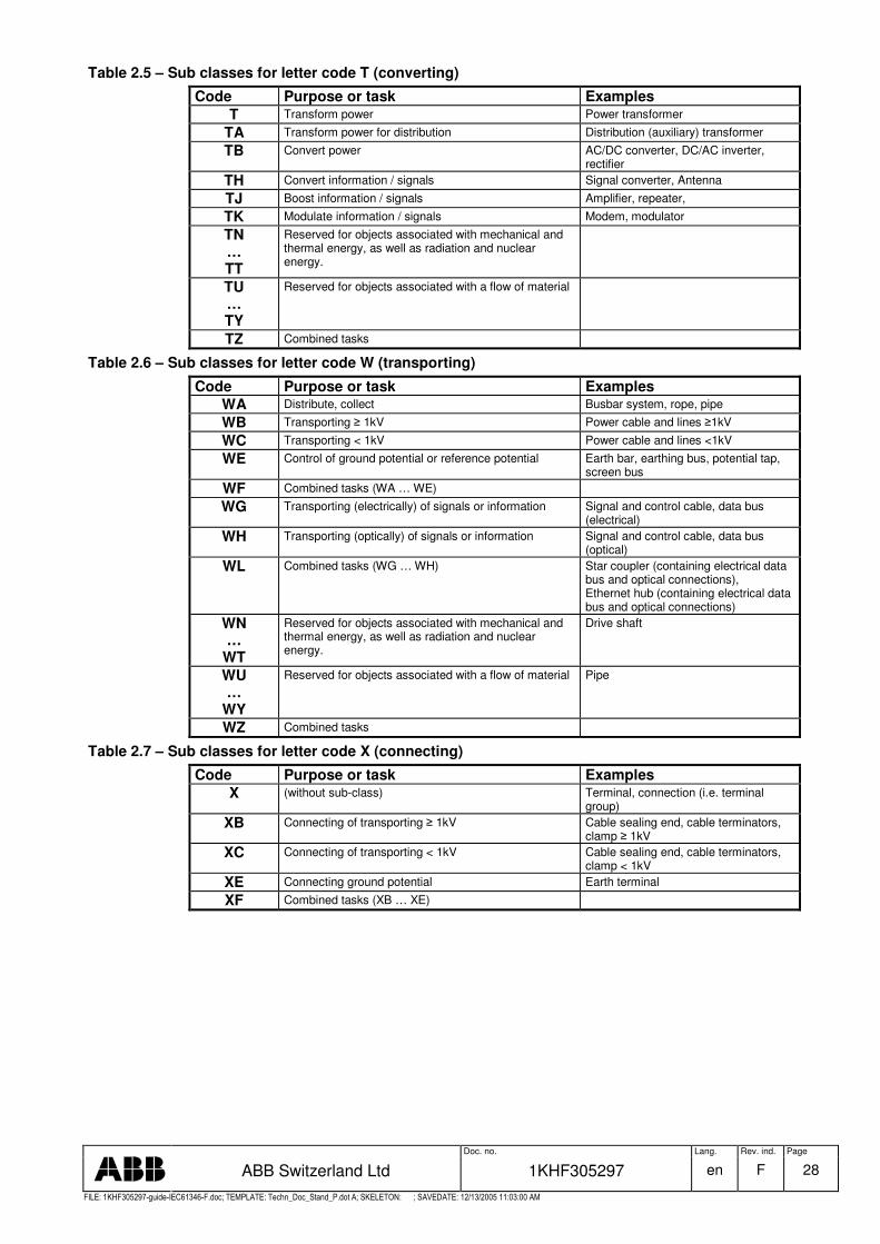
Table 2.5 – Sub classes for letter code T (converting)
Code Purpose or task Examples T Transform power Power transformer
TA Transform power for distribution Distribution (auxiliary) transformer
TB Convert power AC/DC converter, DC/AC inverter, rectifier
TH Convert information / signals Signal converter, Antenna
TJ Boost information / signals Amplifier, repeater,
TK Modulate information / signals Modem, modulator
TN … TT
Reserved for objects associated with mechanical and thermal energy, as well as radiation and nuclear energy.
TU … TY
Reserved for objects associated with a flow of material
TZ Combined tasks
Table 2.6 – Sub classes for letter code W (transporting)
Code Purpose or task Examples WA Distribute, collect Busbar system, rope, pipe
WB Transporting � 1kV Power cable and lines �1kV
WC Transporting < 1kV Power cable and lines <1kV
WE Control of ground potential or reference potential Earth bar, earthing bus, potential tap, screen bus
WF Combined tasks (WA … WE)
WG Transporting (electrically) of signals or information Signal and control cable, data bus (electrical)
WH Transporting (optically) of signals or information Signal and control cable, data bus (optical)
WL Combined tasks (WG … WH) Star coupler (containing electrical data bus and optical connections), Ethernet hub (containing electrical data bus and optical connections)
WN …
WT
Reserved for objects associated with mechanical and thermal energy, as well as radiation and nuclear energy.
Drive shaft
WU …
WY
Reserved for objects associated with a flow of material Pipe
WZ Combined tasks
Table 2.7 – Sub classes for letter code X (connecting)
Code Purpose or task Examples X (without sub-class) Terminal, connection (i.e. terminal
group) XB Connecting of transporting � 1kV Cable sealing end, cable terminators,
clamp � 1kV XC Connecting of transporting < 1kV Cable sealing end, cable terminators,
clamp < 1kV XE Connecting ground potential Earth terminal
XF Combined tasks (XB … XE)

Doc. no. Lang. Rev. ind. Page
ABB Switzerland Ltd 1KHF305297 en F 29
�������� � � � � � �� � �� � ���� � � � � ���� � � ����� � � ������ � ! " # $ � � # % &' " � # � �� � &� ��% � ����( ) ���������% * �$ ����� +� + � � � ����� �� � � � �
11.3 Letter codes for functions running on IEDs and protection functions
The detailed functions running on an intelligent electronic device (including a communication interface) are designated according to IEC 61850-5 and IEC 61850-7-4 (Normative standard for communication networks and systems in substations). All other protection functions are designated by numbers, with appropriate suffix letters (when necessary) according to extract from IEEE C37.2.
61850 means abbreviation/acronyms with a systematic syntax used by IEC 61850
IEEE means device function numbers and contact designations used in IEEE Std C37.2-1996 Electric Power System Device Function Numbers and Contact Designation, if applicable
Functions shown in brackets and light grey are functions that are only defined in IEC 61850-5. This part is not used for communication and therefore these functions have to modeled according to IEC 61850-7-4.
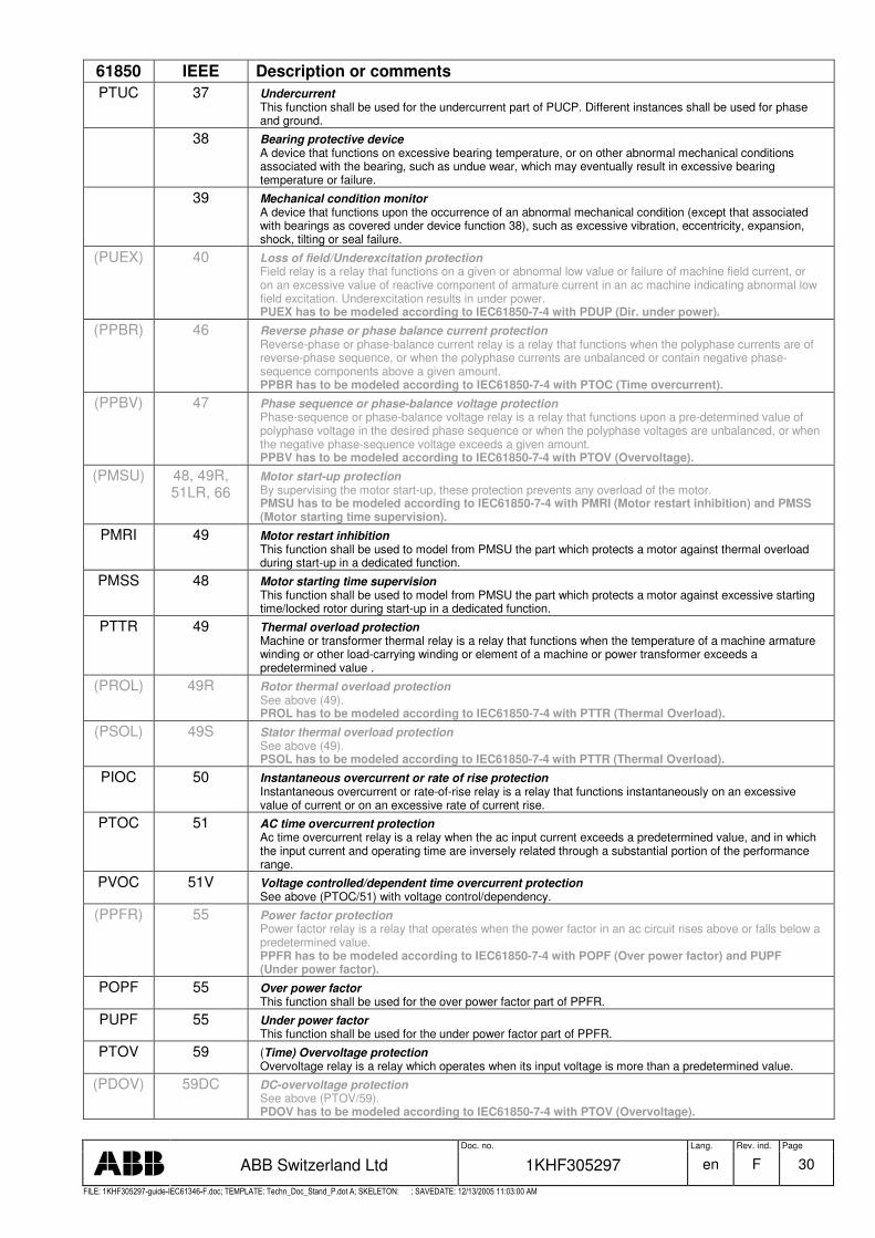
Table 3 - Letter codes for functions running on IEDs and protection functions
61850 IEEE Description or comments PROTECTION FUNCTIONS
PTEF Transient earthfault protection Transient earth faults happen if there is a fault to ground (isolation breakdown) in compensated networks. The fault disappears very fast since there is not sufficient current to feed it. No trip happens but the fault direction/location has to be detected to repair the faulted part. At least the degradation of the impacted line/cable is reported.
12 Overspeed device Usually a direct-connected speed switch that functions on machine overspeed.
PZSU 14 Zero speed and underspeed protection Underspeed device is a device that functions when the speed of a machine falls below a pre-determined value
PDIS 21 Distance protection Distance relay is a relay that functions when the circuit admittance, impedance, or reactance increases or decreases beyond a predetermined value. The change of the impedance seen by PDIS is caused by a fault. The impedance characteristic is a closed line set in the complex impedance plane. - The reach of the distance protection is normally split into different zones (e.g. 1…4 forward and 1 backward) represented by dedicated characteristics. PDIS has to be modeled according to IEC61850-7-4 with one instance of PDIS per zone and with PSCH (Protection scheme).
PVPH 24 Volt per Hz protection Voltage per Hertz relay is a relay that functions when the ratio of voltage to frequency exceeds a preset value. The relay may have an instantaneous or a time characteristic.
PTUV 27 (Time) Undervoltage protection Undervoltage relay is a relay that operates when its input voltage is less than a predetermined value.
(PDPR)
32, 32R Directional power (32) /reverse power protection (32R) Directional power relay is a relay which operates on a predetermined value of power flow in a given direction, or upon reverse power flow such as that resulting from the motoring of a generator upon loss of its prime mover. PDPR has to be modeled according to IEC61850-7-4 with either PDOP (Dir. over power) or PDUP (Dir. under power).
PDOP 32, 32R Directional over power This function shall be used for the overpower part of PDPR. Additionally PDOP is used to model a reverse overpower function (32R).
PDUP 32 Directional under power This function shall be used for the underpower part of PDPR, PUCP and PUEX.
(PWDE) 32 Directional earth fault protection for compensated networks based on wattmetric principle This directional power relay is a relay, which operates on a predetermined value of earth fault power flow in a given direction in compensated networks. Depending on protection philosophy and quality of current transducers it is used as fault indication only or for tripping also. PWDE has to be modeled according to IEC61850-7-4 with PSDE (Sensitive earth fault protection).
PSDE 32 Sensitive earth fault protection This function is used for directional earthfault handling in compensated and isolated networks. For compensated networks, this function is often called wattmetric directional earthfault. The very high accuracy needed for fault current measurement in compensated networks may require phase angle compensation. This shall be realised by the related TCTR.
(PUCP) 37 Undercurrent/underpower protection Undercurrent or underpower relay is a relay that functions when the current or power flow decreases below a predetermined value. PUCP has to be modeled according to IEC61850-7-4 with PTUC (Undercurrent) and PDUP (Under power).
Doc. no. Lang. Rev. ind. Page
ABB Switzerland Ltd 1KHF305297 en F 30
�������� � � � � � �� � �� � ���� � � � � ���� � � ����� � � ������ � ! " # $ � � # % &' " � # � �� � &� ��% � ����( ) ���������% * �$ ����� +� + � � � ����� �� � � � �
61850 IEEE Description or comments PTUC 37 Undercurrent
This function shall be used for the undercurrent part of PUCP. Different instances shall be used for phase and ground.
38 Bearing protective device A device that functions on excessive bearing temperature, or on other abnormal mechanical conditions associated with the bearing, such as undue wear, which may eventually result in excessive bearing temperature or failure.
39 Mechanical condition monitor A device that functions upon the occurrence of an abnormal mechanical condition (except that associated with bearings as covered under device function 38), such as excessive vibration, eccentricity, expansion, shock, tilting or seal failure.
(PUEX) 40 Loss of field/Underexcitation protection Field relay is a relay that functions on a given or abnormal low value or failure of machine field current, or on an excessive value of reactive component of armature current in an ac machine indicating abnormal low field excitation. Underexcitation results in under power. PUEX has to be modeled according to IEC61850-7-4 with PDUP (Dir. under power).
(PPBR) 46 Reverse phase or phase balance current protection Reverse-phase or phase-balance current relay is a relay that functions when the polyphase currents are of reverse-phase sequence, or when the polyphase currents are unbalanced or contain negative phase-sequence components above a given amount. PPBR has to be modeled according to IEC61850-7-4 with PTOC (Time overcurrent).
(PPBV) 47 Phase sequence or phase-balance voltage protection Phase-sequence or phase-balance voltage relay is a relay that functions upon a pre-determined value of polyphase voltage in the desired phase sequence or when the polyphase voltages are unbalanced, or when the negative phase-sequence voltage exceeds a given amount. PPBV has to be modeled according to IEC61850-7-4 with PTOV (Overvoltage).
(PMSU) 48, 49R, 51LR, 66
Motor start-up protection By supervising the motor start-up, these protection prevents any overload of the motor. PMSU has to be modeled according to IEC61850-7-4 with PMRI (Motor restart inhibition) and PMSS (Motor starting time supervision).
PMRI 49 Motor restart inhibition This function shall be used to model from PMSU the part which protects a motor against thermal overload during start-up in a dedicated function.
PMSS 48 Motor starting time supervision This function shall be used to model from PMSU the part which protects a motor against excessive starting time/locked rotor during start-up in a dedicated function.
PTTR 49 Thermal overload protection Machine or transformer thermal relay is a relay that functions when the temperature of a machine armature winding or other load-carrying winding or element of a machine or power transformer exceeds a predetermined value .
(PROL) 49R Rotor thermal overload protection See above (49). PROL has to be modeled according to IEC61850-7-4 with PTTR (Thermal Overload).
(PSOL) 49S Stator thermal overload protection See above (49). PSOL has to be modeled according to IEC61850-7-4 with PTTR (Thermal Overload).
PIOC 50 Instantaneous overcurrent or rate of rise protection Instantaneous overcurrent or rate-of-rise relay is a relay that functions instantaneously on an excessive value of current or on an excessive rate of current rise.
PTOC 51 AC time overcurrent protection Ac time overcurrent relay is a relay when the ac input current exceeds a predetermined value, and in which the input current and operating time are inversely related through a substantial portion of the performance range.
PVOC 51V Voltage controlled/dependent time overcurrent protection See above (PTOC/51) with voltage control/dependency.
(PPFR) 55 Power factor protection Power factor relay is a relay that operates when the power factor in an ac circuit rises above or falls below a predetermined value. PPFR has to be modeled according to IEC61850-7-4 with POPF (Over power factor) and PUPF (Under power factor).
POPF 55 Over power factor This function shall be used for the over power factor part of PPFR.
PUPF 55 Under power factor This function shall be used for the under power factor part of PPFR.
PTOV 59 (Time) Overvoltage protection Overvoltage relay is a relay which operates when its input voltage is more than a predetermined value.
(PDOV) 59DC DC-overvoltage protection See above (PTOV/59). PDOV has to be modeled according to IEC61850-7-4 with PTOV (Overvoltage).

Doc. no. Lang. Rev. ind. Page
ABB Switzerland Ltd 1KHF305297 en F 31
�������� � � � � � �� � �� � ���� � � � � ���� � � ����� � � ������ � ! " # $ � � # % &' " � # � �� � &� ��% � ����( ) ���������% * �$ ����� +� + � � � ����� �� � � � �
61850 IEEE Description or comments (PVCB) 60 Voltage or current balance protection
Voltage or current balance relay is a relay that operates on a given difference on voltage, or current input or output, of two circuits. PVCB has to be modeled according to IEC61850-7-4 with either PTOV (Overvoltage) or PTOC (Time overcurrent) regarding the magnitude of the difference.
PHIZ 64 Earth fault protection/Ground detection Ground detector relay is a relay that operates on failure of machine or other apparatus insulation to ground.
(PREF) 64R Rotor earth fault protection See above (PHIZ/64). PREF has to be modeled according to IEC61850-7-4 with PTOC (Time overcurrent).
(PSEF) 64S Stator earth fault protection See above (PHIZ/64). PSEF has to be modeled according to IEC61850-7-4 with PTOC (Time overcurrent).
(PITF) 64W Interturn fault protection See above (PHIZ/64) PITF has to be modeled according to IEC61850-7-4 with PTOC (Time overcurrent).
(PDOC) 67 AC directional overcurrent protection Ac directional overcurrent relay is a relay that functions on a desired value of ac overcurrent flowing in a predetermined direction PDOC has to be modeled according to IEC61850-7-4 with PTOC (Time overcurrent).
(PDEF) 67N Directional earth fault protection See above (PDOC/67) PDEF has to be modeled according to IEC61850-7-4 with PTOC (Time overcurrent).
(PDCO) 76 DC time overcurrent protection Dc overcurrent relay is a relay that functions when the current in a dc circuit exceeds a given value. PDCO has to be modeled according to IEC61850-7-4 with PTOC (Time overcurrent).
PPAM 78 Phase angle or out-of-step protection Phase-angle measuring or out-of-step protective relay is a relay that functions at a predetermined phase angle between two voltages or between two currents or between voltage and current
(PFRQ) 81 Frequency protection Frequency relay is a relay that responds to the frequency of an electric quantity, operating when the frequency or change of frequency exceeds or is less than a predetermined value. PFRQ has to be modeled according to IEC61850-7-4 with PTOF (Over frequency) and PTUF (Under frequency) and PFRC (Rate of change of frequency).
PTOF 81 Overfrequency This function shall be used for the overfrequency factor part of PPFR.
PTUF 81 Underfrequency This function shall be used for the underfrequency factor part of PPFR.
PFRC 81 Rate of change of frequency This function shall be used for the rate of change of frequendy factor part of PPFR.
PDIF 87 Differential protection Differential protective relay is a protective relay that functions on a percentage or phase angle or other quantitative difference of two currents or some other electrical quantities.
(PPDF) 87P Phase comparison protection See above (PDIF/87) PPDF has to be modeled according to IEC61850-7-4 with PDIF (Differential).
(PLDF) 87L Differential line protection See above (PDIF/87) LPDF has to be modeled according to IEC61850-7-4 with PDIF (Differential).
(PNDF) 87N Restricted earth fault protection See above (PDIF/87). PNDF has to be modeled according to IEC61850-7-4 with PDIF (Differential).
(PTDF) 87T Differential transformer protection See above (PDIF/87) – Special for transformers are inrush currents with dedicated harmonics, which have to be considered by the transformer protection. PTDF has to be modeled acc. to IEC61850-7-4 with PDIF (Differential) and PHAR (Harmonic restraint).
PHAR Harmonic restraint This function shall be used to represent the harmonic restraint data of the transformer differential protection (PTDF) in a dedicated node. There may be multiple instantiations of this function with different settings.
(PMDF) 87M Motor differential protection See above (PDIF/87). PMDF has to be modeled according to IEC61850-7-4 with PDIF (Differential).
(PGDF) 87G Generator differential protection See above (PDIF/87). PGDF has to be modeled according to IEC61850-7-4 with PDIF (Differential).
(PBDF) 87B Busbar protection See above (PPDF/87) – The complexity of the busbar node with changing topology up to a split into two or more nodes needs special means like a dynamic busbar image.- It has to be considered that at least a
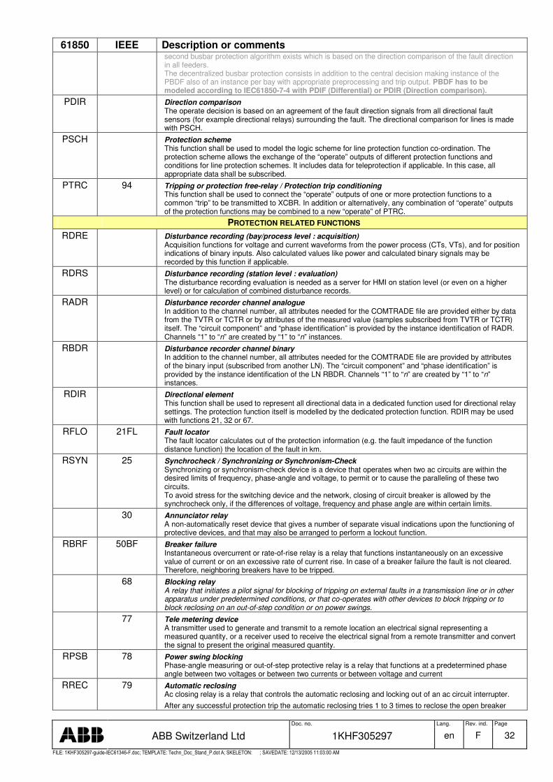
Doc. no. Lang. Rev. ind. Page
ABB Switzerland Ltd 1KHF305297 en F 32
�������� � � � � � �� � �� � ���� � � � � ���� � � ����� � � ������ � ! " # $ � � # % &' " � # � �� � &� ��% � ����( ) ���������% * �$ ����� +� + � � � ����� �� � � � �
61850 IEEE Description or comments second busbar protection algorithm exists which is based on the direction comparison of the fault direction in all feeders. The decentralized busbar protection consists in addition to the central decision making instance of the PBDF also of an instance per bay with appropriate preprocessing and trip output. PBDF has to be modeled according to IEC61850-7-4 with PDIF (Differential) or PDIR (Direction comparison).
PDIR Direction comparison The operate decision is based on an agreement of the fault direction signals from all directional fault sensors (for example directional relays) surrounding the fault. The directional comparison for lines is made with PSCH.
PSCH Protection scheme This function shall be used to model the logic scheme for line protection function co-ordination. The protection scheme allows the exchange of the “operate” outputs of different protection functions and conditions for line protection schemes. It includes data for teleprotection if applicable. In this case, all appropriate data shall be subscribed.
PTRC 94 Tripping or protection free-relay / Protection trip conditioning This function shall be used to connect the “operate” outputs of one or more protection functions to a common “trip” to be transmitted to XCBR. In addition or alternatively, any combination of “operate” outputs of the protection functions may be combined to a new “operate” of PTRC.
PROTECTION RELATED FUNCTIONS RDRE Disturbance recording (bay/process level : acquisition)
Acquisition functions for voltage and current waveforms from the power process (CTs, VTs), and for position indications of binary inputs. Also calculated values like power and calculated binary signals may be recorded by this function if applicable.
RDRS Disturbance recording (station level : evaluation) The disturbance recording evaluation is needed as a server for HMI on station level (or even on a higher level) or for calculation of combined disturbance records.
RADR Disturbance recorder channel analogue In addition to the channel number, all attributes needed for the COMTRADE file are provided either by data from the TVTR or TCTR or by attributes of the measured value (samples subscribed from TVTR or TCTR) itself. The “circuit component” and “phase identification” is provided by the instance identification of RADR. Channels “1” to “n” are created by “1” to “n” instances.
RBDR Disturbance recorder channel binary In addition to the channel number, all attributes needed for the COMTRADE file are provided by attributes of the binary input (subscribed from another LN). The “circuit component” and “phase identification” is provided by the instance identification of the LN RBDR. Channels “1” to “n” are created by “1” to “n” instances.
RDIR Directional element This function shall be used to represent all directional data in a dedicated function used for directional relay settings. The protection function itself is modelled by the dedicated protection function. RDIR may be used with functions 21, 32 or 67.
RFLO 21FL Fault locator The fault locator calculates out of the protection information (e.g. the fault impedance of the function distance function) the location of the fault in km.
RSYN 25 Synchrocheck / Synchronizing or Synchronism-Check Synchronizing or synchronism-check device is a device that operates when two ac circuits are within the desired limits of frequency, phase-angle and voltage, to permit or to cause the paralleling of these two circuits. To avoid stress for the switching device and the network, closing of circuit breaker is allowed by the synchrocheck only, if the differences of voltage, frequency and phase angle are within certain limits.
30 Annunciator relay A non-automatically reset device that gives a number of separate visual indications upon the functioning of protective devices, and that may also be arranged to perform a lockout function.
RBRF 50BF Breaker failure Instantaneous overcurrent or rate-of-rise relay is a relay that functions instantaneously on an excessive value of current or on an excessive rate of current rise. In case of a breaker failure the fault is not cleared. Therefore, neighboring breakers have to be tripped.
68 Blocking relay A relay that initiates a pilot signal for blocking of tripping on external faults in a transmission line or in other apparatus under predetermined conditions, or that co-operates with other devices to block tripping or to block reclosing on an out-of-step condition or on power swings.
77 Tele metering device A transmitter used to generate and transmit to a remote location an electrical signal representing a measured quantity, or a receiver used to receive the electrical signal from a remote transmitter and convert the signal to present the original measured quantity.
RPSB 78 Power swing blocking Phase-angle measuring or out-of-step protective relay is a relay that functions at a predetermined phase angle between two voltages or between two currents or between voltage and current
RREC 79 Automatic reclosing Ac closing relay is a relay that controls the automatic reclosing and locking out of an ac circuit interrupter. After any successful protection trip the automatic reclosing tries 1 to 3 times to reclose the open breaker

Doc. no. Lang. Rev. ind. Page
ABB Switzerland Ltd 1KHF305297 en F 33
�������� � � � � � �� � �� � ���� � � � � ���� � � ����� � � ������ � ! " # $ � � # % &' " � # � �� � &� ��% � ����( ) ���������% * �$ ����� +� + � � � ����� �� � � � �
61850 IEEE Description or comments again with different time delays assuming a transient fault.
(RCPW) 85 Carrier or pilot wire protection Carrier or pilot-wire receiver relay is a relay that is operated or restrained by a signal used in connection with carrier-current or dc pilot-wire fault relaying. PDEF has to be modeled according to IEC61850-7-4 with PSCH (Protection scheme). PSCH is used for line protection schemes instead of RCPW.
86 Lockout relay A hand or electrical reset auxiliary relay that is operated upon the occurrence of abnormal conditions to maintain associated equipment or devices inoperative unit it is reset..
CONTROL FUNCTIONS CALH Alarm handling (Creation of group alarms and group events)
For the communication, there is no difference between alarms and events, if a time tag is added to any data transmitted. If several events or alarms have to be combined to group alarms, a separate, configurable function is needed. The related function may be used to calculate new data out of individual data from different functions. Remote acknowledgement with different priority and authority shall be possible. The definition and handling of alarms is an engineering issue.
CSWI Switch controller Controls any switchgear, i.e. the devices described by XCBR and XSWI. The switch control function handles all switchgear operations from the operators and from related automatics. It checks the authorization of the commands. It supervises the command execution and gives an alarm in case if improper ending of the command. It asks for releases from interlocking, synchrocheck, autoreclosure, etc. if applicable.
CPOW Point-on-wave breaker controller. Controls a circuit breaker with point-on-wave switching capability. The point-on-wave breaker controller function provides all functionality to close or open a circuit breaker at a certain instant of time, i.e. a certain point of the voltage or current wave. It is started by request either from CSWI or RREC. For closing it compares similar as RSYN the voltages on both sides of the breaker to get the minimum stress. This holds also if one of the voltages is zero. For opening the point of minimum stress is calculated referring to the current wave. The selection command activates the voltage selection. It calculates the point of minimum stress and issues a closing or opening (depending on the intended command) execute command with an absolute time referring to the requested point-on-wave. For these calculations the conditions in all three phases are considered. If switching per phase is applicable three execution times are provided.
CILO 3 Interlocking function at station and/or bay level Interlocking may be totally centralized or totally decentralized. Since the interlocking rules are basically the same on bay and station level and based on all related position indications the different interlocking logical nodes may be seen as instances of the same logical node interlocking. 1) Interlocking of switchgear at bay level: All interlocking rules referring to a bay are included in this LN. Releases or blockings of requested commands are issued. In case of status changes affecting interlocking blocking commands are issued. 2) Interlocking of switchgear at station level: All interlocking rules referring to the station are included in this LN. Releases or blockings of requested commands are issued. Information with the LN bay interlocking is exchanged
CCGR Cooling group control This function shall be used to control the cooling equipment. One instance per cooling group shall be used.
INTERFACING AND ARCHIVING FUNCTIONS 74 Alarm relay
A relay other than an annunciator, as covered under device function 30, that is used to operate, or to operate in connection with a visual or audible alarm.
IHMI Operator interface Front-panel operator interface at bay level to be used for configuration, etc. and local control. Local operator interface at station level to be used as work place for the station operator. The role of the different HMI is not fixed for most of the functions and is defined in the engineering phase
ITCI Remote control interface or Telecontrol interface Telecontrol interface to be used for remote control from higher control level. Basically, the TCI will communicate the same data as the station level HMI or a subset of these data. The role of the different interfaces is not fixed for most of the functions and defined in the engineering phase
ITMI Remote monitoring interface / Telemonitoring interface Telemonitoring interface to be used for remote monitoring and maintenance using a subset of all information available in the substation and allows no control. The role of the different interfaces is not fixed for most of the functions and def. in the engineering phase
IARC Archiving Archiving to be used as sink and source for long-term historical data, normally used globally for the complete substation on station level.
AUTOMATIC PROCESS CONTROL FUNCTIONS 84 Operating mechanism
The complete electrical mechanism or servomechanism, including the operating motor, solenoids, position switches, etc, for a tap changer, including regulator, or any similar piece of apparatus which otherwise has no device function number.
ATCC 84 Automatic tap changer control Automatics to maintain the voltage of a busbar within a specific range using tap changers. This node
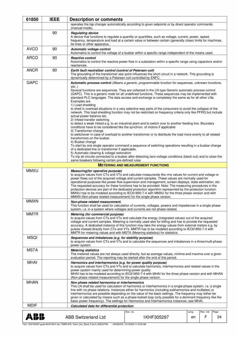
Doc. no. Lang. Rev. ind. Page
ABB Switzerland Ltd 1KHF305297 en F 34
�������� � � � � � �� � �� � ���� � � � � ���� � � ����� � � ������ � ! " # $ � � # % &' " � # � �� � &� ��% � ����( ) ���������% * �$ ����� +� + � � � ����� �� � � � �
61850 IEEE Description or comments operates the tap changer automatically according to given setpoints or by direct operator commands (manual mode).
90 Regulating device A device that functions to regulate a quantity or quantities, such as voltage, current, power, speed, frequency, temperature and load at a certain value or between certain (generally close) limits for machines, tie lines or other apparatus.
AVCO 90 Automatic voltage control Automatics to control the voltage of a busbar within a specific range independent of the means used.
ARCO 90 Reactive control Automatics to control the reactive power flow in a substation within a specific range using capacitors and/or reactances.
ANCR 90 Earth fault neutralizer control (control of Petersen coil) The grounding of the transformer star point influences the short circuit in a network. This grounding is dynamically determined by a Petersen coil controlled by ENFC.
GAPC Automatic process control (Means a generic, programmable function for sequences, unknown functions, etc. ) Several functions are sequences. They are collected in the LN type Generic automatic process control (GAPC). This is a generic node for all undefined functions. These sequences may be implemented with standard PLC languages. The data access and exchange is completely the same as for all other LNs. Examples are 1) Load shedding to shed in overload situations in a very selective way parts of the consumers to avoid the collapse of the network. This load-shedding function may not be restricted on frequency criteria only like PFRQ but include actual power balance etc. 2) Infeed transfer switching to detect a weak infeed e.g. to an industrial plant and to switch over to another feeding line. Boundary conditions have to be considered like the synchron. of motors if applicable 3) Transformer change to switchover in case of overload to another transformer or to distribute the load more evenly to all related transformers on the busbar. 4) Busbar change To start by one single operator command a sequence of switching operations resulting in a busbar change of a dedicated line or transformer if applicable. 5) Automatic clearing & voltage restoration To trip all circuits connected to a busbar after detecting zero-voltage conditions (black-out) and to close the same breakers following certain pre-defined rules
METERING AND MEASUREMENT FUNCTIONS MMXU Measuring(for operative purpose)
to acquire values from CTs and VTs and calculate measurands like rms values for current and voltage or power flows out of the acquired voltage and current samples. These values are normally used for operational purposes like power flow supervision and management, screen displays, state estimation, etc. The requested accuracy for these functions has to be provided. Note: The measuring procedures in the protection devices are part of the dedicated protection algorithm represented by the protection function. MMXU has to be modeled according to IEC61850-7-4 with MMXU for the three phase version and with MMXN (Non-phase related measurement) for the single phase version.
MMXN Non-phase related measurement. This function shall be used for calculation of currents, voltages, powers and impedances in a single phase system, i.e. in a system where voltages and currents are not phase-related.
MMTR Metering (for commercial purpose) to acquire values from CTs and VTs and calculate the energy (integrated values) out of the acquired voltage and current samples. Metering is normally used also for billing and has to provide the requested accuracy. A dedicated instance of this function may take the energy values from external meters e.g. by pulses instead directly from CTs and VTs. MMTR has to be modeled according to IEC61850-7-4 with MMTR for metering values and with MSTA (Metering statistics) for statistics.
MSQI Sequences and imbalances (e.g. for stability purpose) to acquire values from CTs and VTs and to calculate the sequences and imbalances in a three/multi-phase power system.
MSTA Metering statistics The metered values are not always used directly, but as average values, minima and maxima over a given evaluation period. The reporting may be started after the end of this period.
MHAI Harmonics and interharmonics (e.g. for power quality purpose) to acquire values from CTs and VTs and to calculate harmonics, interharmonics and related values in the power system mainly used for determining power quality. MHAI has to be modeled according to IEC61850-7-4 with MHAI for the three phase version and with MHAN (Non-phase related measurement) for the single phase version.
MHAN Non phase related harmonics or interharmonics This LN shall be used for calculation of harmonics or interharmonics in a single-phase system, i.e. a single line with no phase relations. Instances either for harmonics (including subharmonics and multiples) or interharmonics are possible depending on the value of the basic settings. The frequency may either be given or calculated by means such as a phase-locked loop (only possible for a dominant frequency like the basic power frequency). The settings for Harmonics and Interharmonics instances, see MHAI.
MDIF Calculated data for differential protection
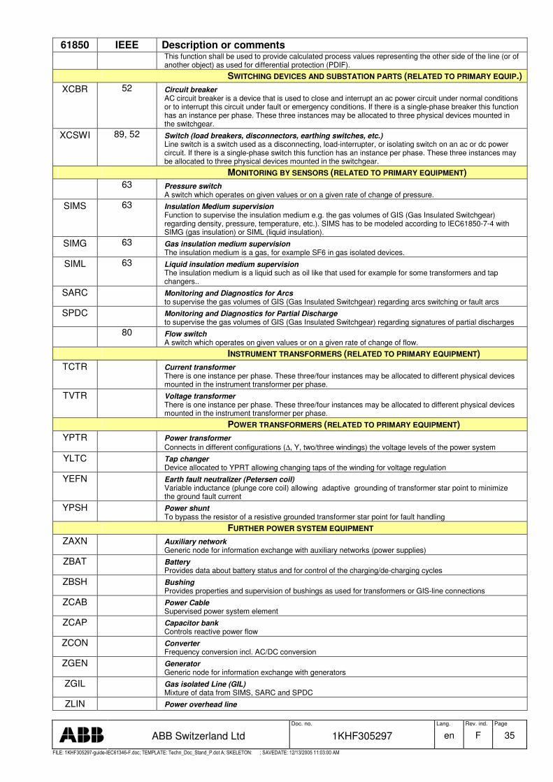
Doc. no. Lang. Rev. ind. Page
ABB Switzerland Ltd 1KHF305297 en F 35
�������� � � � � � �� � �� � ���� � � � � ���� � � ����� � � ������ � ! " # $ � � # % &' " � # � �� � &� ��% � ����( ) ���������% * �$ ����� +� + � � � ����� �� � � � �
61850 IEEE Description or comments This function shall be used to provide calculated process values representing the other side of the line (or of another object) as used for differential protection (PDIF).
SWITCHING DEVICES AND SUBSTATION PARTS (RELATED TO PRIMARY EQUIP.) XCBR 52 Circuit breaker
AC circuit breaker is a device that is used to close and interrupt an ac power circuit under normal conditions or to interrupt this circuit under fault or emergency conditions. If there is a single-phase breaker this function has an instance per phase. These three instances may be allocated to three physical devices mounted in the switchgear.
XCSWI 89, 52 Switch (load breakers, disconnectors, earthing switches, etc.) Line switch is a switch used as a disconnecting, load-interrupter, or isolating switch on an ac or dc power circuit. If there is a single-phase switch this function has an instance per phase. These three instances may be allocated to three physical devices mounted in the switchgear.
MONITORING BY SENSORS (RELATED TO PRIMARY EQUIPMENT) 63 Pressure switch
A switch which operates on given values or on a given rate of change of pressure.
SIMS 63 Insulation Medium supervision Function to supervise the insulation medium e.g. the gas volumes of GIS (Gas Insulated Switchgear) regarding density, pressure, temperature, etc.). SIMS has to be modeled according to IEC61850-7-4 with SIMG (gas insulation) or SIML (liquid insulation).
SIMG 63 Gas insulation medium supervision The insulation medium is a gas, for example SF6 in gas isolated devices.
SIML 63 Liquid insulation medium supervision The insulation medium is a liquid such as oil like that used for example for some transformers and tap changers..
SARC Monitoring and Diagnostics for Arcs to supervise the gas volumes of GIS (Gas Insulated Switchgear) regarding arcs switching or fault arcs
SPDC Monitoring and Diagnostics for Partial Discharge to supervise the gas volumes of GIS (Gas Insulated Switchgear) regarding signatures of partial discharges
80 Flow switch A switch which operates on given values or on a given rate of change of flow.
INSTRUMENT TRANSFORMERS (RELATED TO PRIMARY EQUIPMENT) TCTR Current transformer
There is one instance per phase. These three/four instances may be allocated to different physical devices mounted in the instrument transformer per phase.
TVTR Voltage transformer There is one instance per phase. These three/four instances may be allocated to different physical devices mounted in the instrument transformer per phase.
POWER TRANSFORMERS (RELATED TO PRIMARY EQUIPMENT) YPTR Power transformer
Connects in different configurations (∆, Y, two/three windings) the voltage levels of the power system
YLTC Tap changer Device allocated to YPRT allowing changing taps of the winding for voltage regulation
YEFN Earth fault neutralizer (Petersen coil) Variable inductance (plunge core coil) allowing adaptive grounding of transformer star point to minimize the ground fault current
YPSH Power shunt To bypass the resistor of a resistive grounded transformer star point for fault handling
FURTHER POWER SYSTEM EQUIPMENT ZAXN Auxiliary network
Generic node for information exchange with auxiliary networks (power supplies)
ZBAT Battery Provides data about battery status and for control of the charging/de-charging cycles
ZBSH Bushing Provides properties and supervision of bushings as used for transformers or GIS-line connections
ZCAB Power Cable Supervised power system element
ZCAP Capacitor bank Controls reactive power flow
ZCON Converter Frequency conversion incl. AC/DC conversion
ZGEN Generator Generic node for information exchange with generators
ZGIL Gas isolated Line (GIL) Mixture of data from SIMS, SARC and SPDC
ZLIN Power overhead line
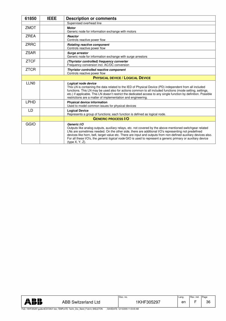
Doc. no. Lang. Rev. ind. Page
ABB Switzerland Ltd 1KHF305297 en F 36
�������� � � � � � �� � �� � ���� � � � � ���� � � ����� � � ������ � ! " # $ � � # % &' " � # � �� � &� ��% � ����( ) ���������% * �$ ����� +� + � � � ����� �� � � � �
61850 IEEE Description or comments Supervised overhead line
ZMOT Motor Generic node for information exchange with motors
ZREA Reactor Controls reactive power flow
ZRRC Rotating reactive component Controls reactive power flow
ZSAR Surge arrestor Generic node for information exchange with surge arrestors
ZTCF (Thyristor controlled) frequency converter Frequency conversion incl. AC/DC conversion
ZTCR Thyristor controlled reactive component Controls reactive power flow
PHYSICAL DEVICE / LOGICAL DEVICE LLN0 Logical node device
This LN is containing the data related to the IED of Physical Device (PD) independent from all included functions. This LN may be used also for actions common to all included functions (mode setting, settings, etc.) if applicable. This LN doesn’t restrict the dedicated access to any single function by definition. Possible restrictions are a matter of implementation and engineering.
LPHD Physical device information Used to model common issues for physical devices
LD Logical Device Represents a group of functions; each function is defined as logical node.
GENERIC PROCESS I/O GGIO Generic I/O
Outputs like analog outputs, auxiliary relays, etc. not covered by the above-mentioned switchgear related LNs are sometimes needed. On the other side, there are additional I/O's representing not predefined devices like horn, bell, target value etc. There are input and outputs from non-defined auxiliary devices also. For all these I/O's, the generic logical node GIO is used to represent a generic primary or auxiliary device (type X, Y, Z).
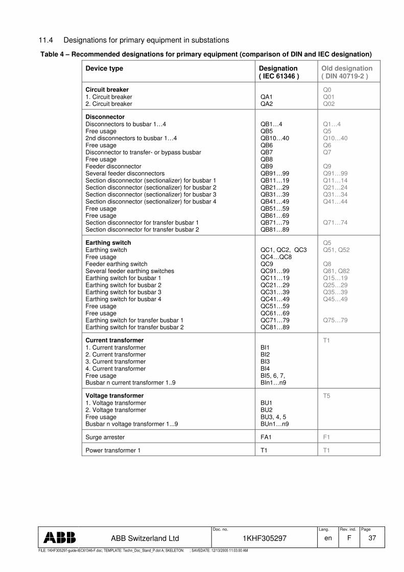
Doc. no. Lang. Rev. ind. Page
ABB Switzerland Ltd 1KHF305297 en F 37
�������� � � � � � �� � �� � ���� � � � � ���� � � ����� � � ������ � ! " # $ � � # % &' " � # � �� � &� ��% � ����( ) ���������% * �$ ����� +� + � � � ����� �� � � � �
11.4 Designations for primary equipment in substations
Table 4 – Recommended designations for primary equipment (comparison of DIN and IEC designation)
Device type Designation ( IEC 61346 )
Old designation ( DIN 40719-2 )
Circuit breaker 1. Circuit breaker 2. Circuit breaker
QA1 QA2
Q0 Q01 Q02
Disconnector Disconnectors to busbar 1…4 Free usage 2nd disconnectors to busbar 1…4 Free usage Disconnector to transfer- or bypass busbar Free usage Feeder disconnector Several feeder disconnectors Section disconnector (sectionalizer) for busbar 1 Section disconnector (sectionalizer) for busbar 2 Section disconnector (sectionalizer) for busbar 3 Section disconnector (sectionalizer) for busbar 4 Free usage Free usage Section disconnector for transfer busbar 1 Section disconnector for transfer busbar 2
QB1…4 QB5 QB10…40 QB6 QB7 QB8 QB9 QB91…99 QB11…19 QB21…29 QB31…39 QB41…49 QB51…59 QB61…69 QB71…79 QB81…89
Q1…4 Q5 Q10…40 Q6 Q7 Q9 Q91…99 Q11…14 Q21…24 Q31…34 Q41…44 Q71…74
Earthing switch Earthing switch Free usage Feeder earthing switch Several feeder earthing switches Earthing switch for busbar 1 Earthing switch for busbar 2 Earthing switch for busbar 3 Earthing switch for busbar 4 Free usage Free usage Earthing switch for transfer busbar 1 Earthing switch for transfer busbar 2
QC1, QC2, QC3 QC4…QC8 QC9 QC91…99 QC11…19 QC21…29 QC31…39 QC41…49 QC51…59 QC61…69 QC71…79 QC81…89
Q5 Q51, Q52 Q8 Q81, Q82 Q15…19 Q25…29 Q35…39 Q45…49 Q75…79
Current transformer 1. Current transformer 2. Current transformer 3. Current transformer 4. Current transformer Free usage Busbar n current transformer 1..9
BI1 BI2 BI3 BI4 BI5, 6, 7, BIn1…n9
T1
Voltage transformer 1. Voltage transformer 2. Voltage transformer Free usage Busbar n voltage transformer 1...9
BU1 BU2 BU3, 4, 5 BUn1…n9
T5
Surge arrester FA1 F1
Power transformer 1 T1 T1
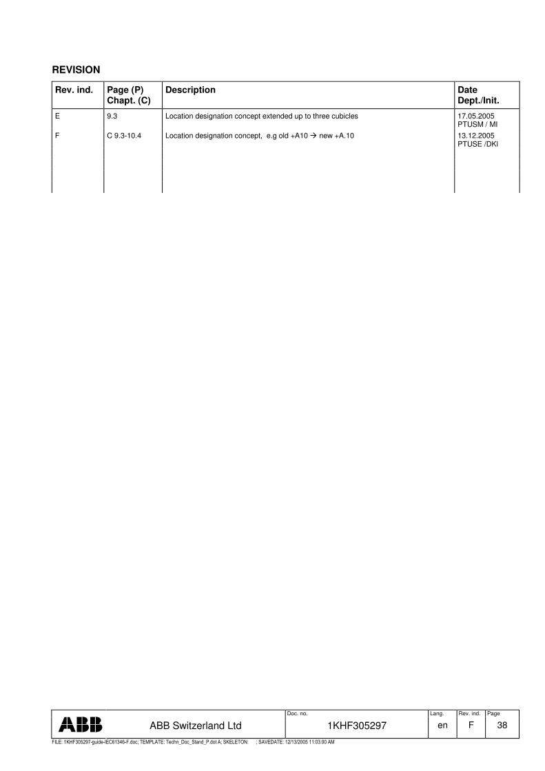
Doc. no. Lang. Rev. ind. Page
ABB Switzerland Ltd 1KHF305297 en F 38
�������� � � � � � �� � �� � ���� � � � � ���� � � ����� � � ������ � ! " # $ � � # % &' " � # � �� � &� ��% � ����( ) ���������% * �$ ����� +� + � � � ����� �� � � � �
REVISION
Rev. ind. Page (P) Chapt. (C)
Description Date Dept./Init.
E 9.3 Location designation concept extended up to three cubicles 17.05.2005 PTUSM / MI
F C 9.3-10.4 Location designation concept, e.g old +A10 � new +A.10 13.12.2005 PTUSE /DKl