Embed Size (px)
Citation preview

© ABB Group May 18, 2015 | Slide 1
ABB AlamoDry (Oil-less) bushingsTutorial
MEA – Springfield, IL – May 2015
David M. Geibel, Tecnical Director

Introduction - Transformer
Big Gray
Box
Spark Plugs

We have been “bushings” for a long time

© ABB Group May 18, 2015 | Slide 4
ABB Alamo: World Leader - OIP Condenser Bushings
Standards: IEEE and CSA
25 kV through 550 kV
400 A through 21,500 A

Bushings!
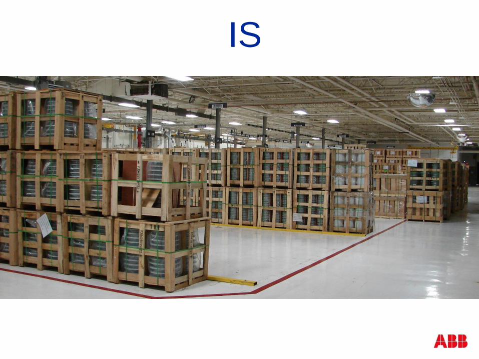
IS

WHO
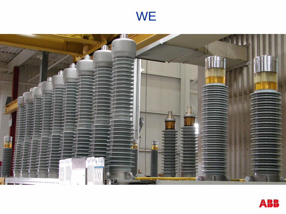
WE

ARE!!!

© ABB Group May 18, 2015 | Slide 10
Why Dry? Why Silicon? Why RIS?
No oil to leak
No oil to contaminate
No oil to burn
No pressure vessel to rupture
High seismic performance
Long life
Easy Storage
100,000+ dry bushings produced

Dry Bushings
Advantages
Reduced risk of fire
Oil leakage is eliminated
Mechanically rigid design and no need for
oil supervision
Seals the transformer and reduces
the down-time in the event of major
TFO failures
Lightweight and compact, less than 50% of
OIP
Transported, stored and installed at
any angle
Can be energized immediately
after installation
Important
Needs to be stored properly long-term
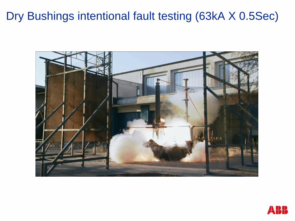
Dry Bushings intentional fault testing (63kA X 0.5Sec)

Voltage Distribution
75%
50%
25%
25%50%
75%
Uncontrolled field follows the laws of nature unequally
stressing porcelain, oil, epoxy and/or paper insulation
system
Field controlled by capacitive
grading follows controlled
contours making effective use of
all insulation
No Capacitive
Grading (bulk
bushing)
Capacitive
Grading (condenser
bushing)

Function of High Voltage Bushing
Capacity-controlled
electrical field
Uncontrolled
(natural) electrical field
0%
voltage
100%
voltage

Electric Field Distribution in and around Bushings
Grounded
flange

Oil Impregnated Paper (OIP)
15 kV to 800 kV
Plain paper condenser body
Core impregnated with hot oil under vacuum
Aluminum foil or ink print gradients
Partial discharge 10 pc at 1.5 times line to ground
Power factor requirements – less than .50%
Resin Bonded Paper (RBP)
Cast Epoxy
Resin Impregnated Paper (RIP)
Resin Impregnated Synthetic (RIS)
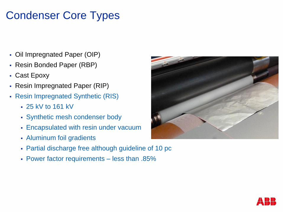
Condenser Core Types

Oil Impregnated Paper (OIP)
Resin Bonded Paper (RBP)
15 kV to 230 kV
Resin treated plain paper condenser body
Dry processed with varnish dipped core
Aluminum foil gradients
Partial discharge 100 pc at 1.5 times line to ground
Power factor requirements – less than 2.0%
Cast Epoxy
Resin Impregnated Paper (RIP)
Resin Impregnated Synthetic (RIS)
Condenser Core Types

Condenser Core Types
Oil Impregnated Paper (OIP)
Resin Bonded Paper (RBP)
Westinghouse type S and OS
Cast Epoxy
Resin Impregnated Paper (RIP)
Resin Impregnated Synthetic
(RIS)

Oil Impregnated Paper (OIP)
Resin Bonded Paper (RBP)
Cast Epoxy
15 kV – 138 kV
Metal screen mesh graded
Epoxy resin condenser body
Partial discharge 25 pc at 1.5 times line to ground
Power factor requirements – less than 1.0%
Resin Impregnated Paper (RIP)
Resin Impregnated Synthetic (RIS)
Condenser Core Types

Oil Impregnated Paper (OIP)
Resin Bonded Paper (RBP)
Cast Epoxy
Resin Impregnated Paper (RIP)
15 kV to 800 kV
Crepe paper condenser body
Resin impregnated core under vacuum
Aluminum foil gradients
Partial discharge free although guideline of 10 pc
Power factor requirements – less than .85%
Resin Impregnated Synthetic (RIS)
Condenser Core Types

Resin Impregnated Paper (RIP)
Condenser Core Types
Oil Impregnated Paper (OIP)
Resin Bonded Paper (RBP)
Cast Epoxy
Resin Impregnated Paper (RIP)
Resin Impregnated Synthetic (RIS)
25 kV to 161 kV
Synthetic mesh condenser body
Encapsulated with resin under vacuum
Aluminum foil gradients
Partial discharge free although guideline of 10 pc
Power factor requirements – less than .85%
Condenser Core Types

Oil Impregnated Paper (OIP)
Resin Bonded Paper (RBP)
Cast Epoxy
Resin Impregnated Paper (RIP)
Resin Impregnated Synthetic (RIS)
Molded design condenser body
Condenser Core Types

RIP vs. OIP technology

RIP Technology
tube / conductor
main insulation
RIP body with
fine gradingdry filling
Micagel
porcelain or
composite insulator test tap
flangeair side
oil side
R esin
I mpregnated
P aper

RIP Technology
Tube / conductor
Main insulation
RIP body with
fine grading
Dry filling
Micagel
Porcelain or
composite
insulator
Flange
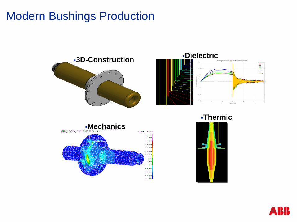
Modern Bushings Production
3D-ConstructionDielectric
Mechanics
Thermic

Modern RIP Bushings Production
Conductor:
- Al, Cu,
- solid, tube
Special
crepe paper
Aluminium
foils

Modern Bushings Production
Winding-Process
Paper -Drying
Resin-Impregnating
Curing Process

RIP Bushings Technical Facts
Low dielectric losses (Power Factor < 0,4%)
PD “free“up to double service voltage
Excellent mechanical strength
Excellent Siemic withstand capablity
Fire resistant (oil free)
High thermal strength (class E, 120°C )
No oil to leak out, contaminate, degrade
High design flexiblity for custom mechanical fit

SeismicRIP® Bushings
SeismicRIP® Bushings
New line of SeismicRIP® Oil/Air Bushings
Satisfing the highest requests as perIEEE Standard 693
Nominal voltages from 69 up to 550kV
RIP technology with composite insulator
Delivered to Californian utilities

Transformer BushingsOil – Air application
High Voltage Bushings
24-550 kV
up to 5,000 A
with
porcelain or
silicone composite insulator
SeismicRIP ® Bushings
69-550 kV
up to 5,000 A
only with silicone composite insulator

Transformer BushingsOil – Oil bushings
for cable box
72.5 – 550 kV
up to 4000 A
with double flange available

Transformer BushingsOil – SF 6 application
For GIS connection
72.5 – 550 kV
Up to 4000 A

GSU Transformer BushingsOil – Air high current
17,5 – 52 kV
Up to 40kA
With
Porcelain
Silicone composite
insulators

Three Gorges Project – China
Micafil supplied:
SF6/Air bushings550 kV, 4000 A
Transformer high current bushings24 kV, 35,000 A

© ABB Group May 18, 2015 | Slide 37
ABB Alamo: O Plus Dry™
Standards: IEEE
2015
25 kV through 138 kV
400 A through 1,200 A
By late 2015
25 kV through 138 kV
2000 & 3000 Ampere
Coming soon:
230kV (800 – 5,000 Amp)
69kV
400/1200A

Same condenser theory
1 2
4 56
1
2
4
5
3
6
2 4 53 61
V/6
V/6
V/6
V/6
V/6
V/6
V
2 4 5 631
6/6 V
5/6 V
4/6 V
3/6 V
2/6 V
1/6 V
Effect of Capacitive Grading
Capacitive Layer
3
CL

EasyDry Bushing Construction Synthetic mesh fabric
Used in winding
condenser
Provides structure &
supports foils that form
condenser
Open structure allows
easy impregnation
Synthetic material
does not absorb
moisture

EasyDry Bushing Construction Isolation of conductor

EasyDry Bushing Construction Synthetic mesh fabric winding

EasyDry Bushing Construction Foil “Equalizers”

© ABB Group May 18, 2015 | Slide 43
New CondenserType O Plus Dry™
Windings
Conductor
Isolator
Synthetic Mesh
Equalizer Foils
Tap connections
Condenser
Winding
Filled Epoxy
No Machining
Condenser
Winding

EasyDry Bushing Construction Critical Resin Curing

EasyDry Bushing Construction Epoxy “factory”

© ABB Group May 18, 2015 | Slide 46
New CondenserType O Plus Dry™
Windings
Conductor
Isolator
Synthetic Mesh
Equalizer Foils
Tap connections
Condenser
Winding
Filled Epoxy
No Machining
Condenser
Winding

EasyDry Bushing Construction Flange Installation
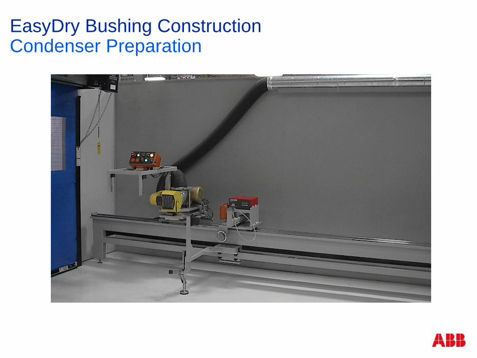
EasyDry Bushing Construction Condenser Preparation

© ABB Group May 18, 2015 | Slide 49
New Manufacturing PracticesType O Plus Dry™ Weather shed extruder
World class silicon
High Temperature Vulcanized
Modern shed profile
Infinitely variable
Reduced lead time
© ABB Group May 18, 2015 | Slide 50
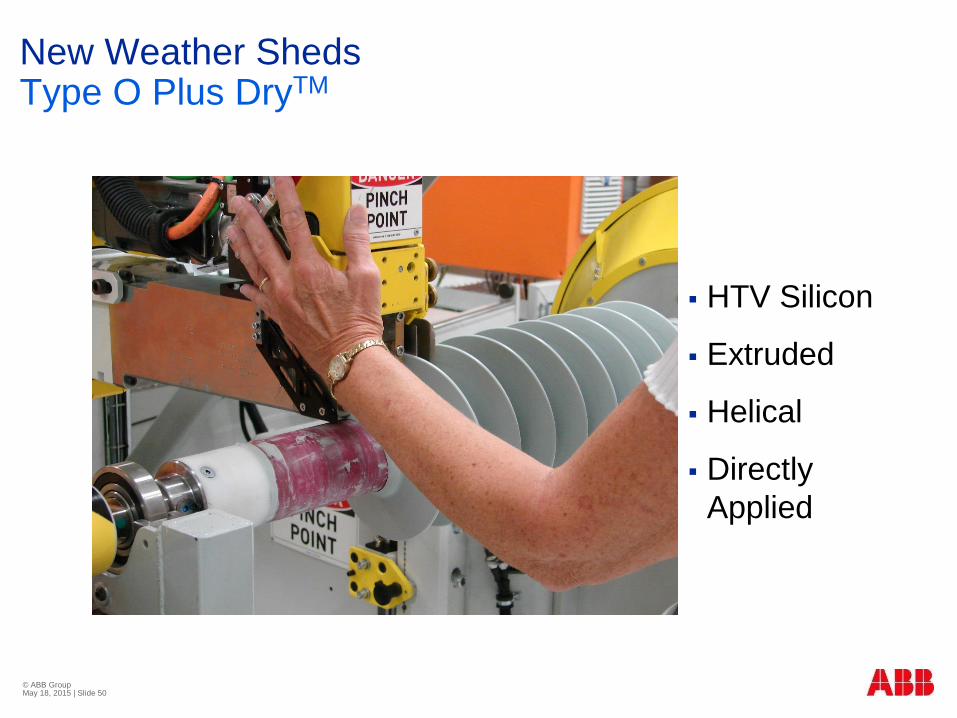
New Weather Sheds Type O Plus DryTM
HTV Silicon
Extruded
Helical
Directly
Applied

© ABB Group May 18, 2015 | Slide 51
New Weather Sheds Type O Plus DryTM
“Homogeneous”
turn-to-turn joint
(Undetectable
joint)

EasyDry Bushing Construction Final Assembly

Resin Impregnated Synthetic

Circuit
BreakersCable
Terminations
Instrument
Transformers
Bushings Surge
Arresters
Composite Insulator Aplication through 1200kV AC/DC

Just ABB Service experience
World wide in > 60 countries and >80 000 composite
insulators

Glass fiber reinforced
epoxy resin tube
Silicone rubber sheds
Aluminum end fitting
Composite insulatorsOne-piece design

Glass fiber reinforced epoxy resin tube using wet filament winding technique
Tailored mechanical and electrical performance
Continuous one-piece tube design for length >15 m (no gluing of tube segments)
Conical and cylindrical design available in length >15 m
Glass fiber composite tubeOne-piece design
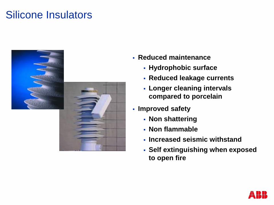
Silicone Insulators
Reduced maintenance
Hydrophobic surface
Reduced leakage currents
Longer cleaning intervals
compared to porcelain
Improved safety
Non shattering
Non flammable
Increased seismic withstand
Self extinguishing when exposed
to open fire

Hydrophobicity
Silicone is by nature more
hydrophobic than porcelain or
other polymers
Constant diffusion of silicones to
the surface
Water on a hydrophobic surface
stays as water droplets and does
not form a continuous film
Automatic hydrophobicity recovery
after possible temporary reduction
under constant heavy pollution
No ageing effect on hydrophobicity
Gives excellent pollution
performance with minimum
maintenance

Maintenance of HTV shed bushings
Self-Cleaning(Hydrophobic = self cleaning)
Degrees of hydrophobic performance
Good Bad

Advantages with Silicone Rubber Sheds
Flashover resistant
Insulator surface hydrophobic
Water stays as droplets
The leakage currents are suppressed
Tracking resistant
Ageing withstand
Less discharge activity in case of severe
pollution
UV stability
Max. absorption below wavelength
of natural UV-light
Mechanical strength
Elastic and stable over a wide
temperature range

Composite insulatorsManufacturing processes

One continuous seamless outer silicone housing for length >15 m
Manufacturing in one step without parting lines/ mold lines or joints
Flexible production method for different diameters, lengths, shapes and creepage distances
Silicone rubber housing Seamless helical extrusion process

Shed tip with large radius and “drip edge” to minimize the electrical field and the risk of flashover
Inclined bottom surface gives high protective creepagedistance and lowest possible leakage currents
Special shed profile fulfilling requirements for 800 kV UHVDC
Silicone rubber housing Optimized shed profiles
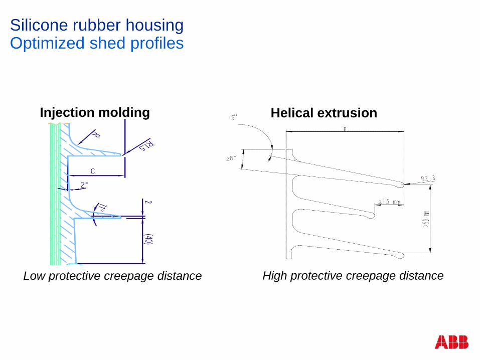
Injection molding Helical extrusion
High protective creepage distanceLow protective creepage distance
Silicone rubber housing Optimized shed profiles

Injection
moldingHelical
extrusion
No mold linesMold lines
Low electrical fieldHigh electrical field
Shed profile ≠ Shed profile
Silicone rubber housing Optimized shed profiles

ExperienceWell verified design
Quality and -50°C performance approved by Hydro Quebec
Pressure cycling test ANSI C37.09
10 000 cycles 0 to MSP at -40°C
90 000 cycles 0 to MSP at +100°C
Performed on several insulators, including the most severely loaded tube and joint in pressure
Tube surge arresters qualified for -60°C IEC60099-4
Performed on the most severely loaded joint in bending
Long term performance verified in field and test stations
Dungeness, UK
Guangzhou, CN
Ludvika (800 kV DC), SE
Koeberg (KIPTS), ZA

Silicone rubber materialHTV for reliable performance
Silicone rubber usually discussed in 3
general classes
RTV - Room temperature
vulcanizing
LSR - Liquid silicone rubber
HTV - High temperature vulcanizing
ABB HTV Insulator after 1 year KIPTS test
Lower quality Insulator after 1 year KIPTS test
Silicone Rubber ≠ Silicone
Rubber

Koeberg Insulator Pollution Test Station (KIPTS)ESKOM, ZA
Severe test station for pollution and ageing performance of insulators
Very harsh environment for insulators:
Salt fog
Strong UV light
Sand
Industrial pollution
Pollution level up to 6 times “very heavy” from IEC 60815
12 month test cycle

Severe service experience Long term test at KIPTS
Composite
Insulators tested
successfully at
Koeberg Insulator
Pollution Test
Station (KIPTS)
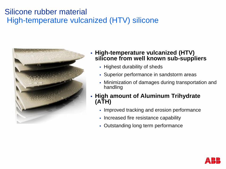
High-temperature vulcanized (HTV) silicone from well known sub-suppliers
Highest durability of sheds
Superior performance in sandstorm areas
Minimization of damages during transportation and handling
High amount of Aluminum Trihydrate(ATH)
Improved tracking and erosion performance
Increased fire resistance capability
Outstanding long term performance
Silicone rubber materialHigh-temperature vulcanized (HTV) silicone

Bushing after 4 years at coastal testing station
(IEC pollution level IV - Very Heavy)
Severe service experience Long term test at Dungeress, UK

ABB Composite Insulator Training
Handling, cleaning, repair

Handling
Put slings around flanges, never on silicone
Be careful with sealing surfaces and silicone
Protect sheds during assembly, construction and
maintenance
Picture courtesy of CIGRE WG3.21

Maintenance of HTV shed bushings
Cleaning
Hydrophobic and self cleaning
The right Alcohol!!
Denatured Alcohol is poisoned ethanol (poisoned with
what???)
Methanol is not recommended
Use Isopropyl Alcohol contaminated/diluted only with
water.
Water with or without mild detergent is ok if rinsed.
Repair?

On site repairable damage types
Type A. Cut or crack at shed tip
Type B. Closed cut or crack
in shed
Type C. Piece of shed is
broken

ABB Composite Insulator Training
Summary
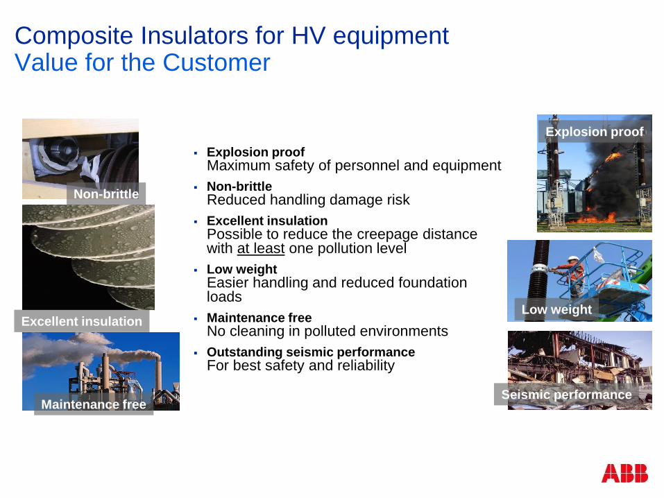
Explosion proofMaximum safety of personnel and equipment
Non-brittleReduced handling damage risk
Excellent insulationPossible to reduce the creepage distance with at least one pollution level
Low weightEasier handling and reduced foundation loads
Maintenance freeNo cleaning in polluted environments
Outstanding seismic performanceFor best safety and reliability
Explosion proof
Non-brittle
Excellent insulationLow weight
Maintenance freeSeismic performance
Composite Insulators for HV equipment Value for the Customer
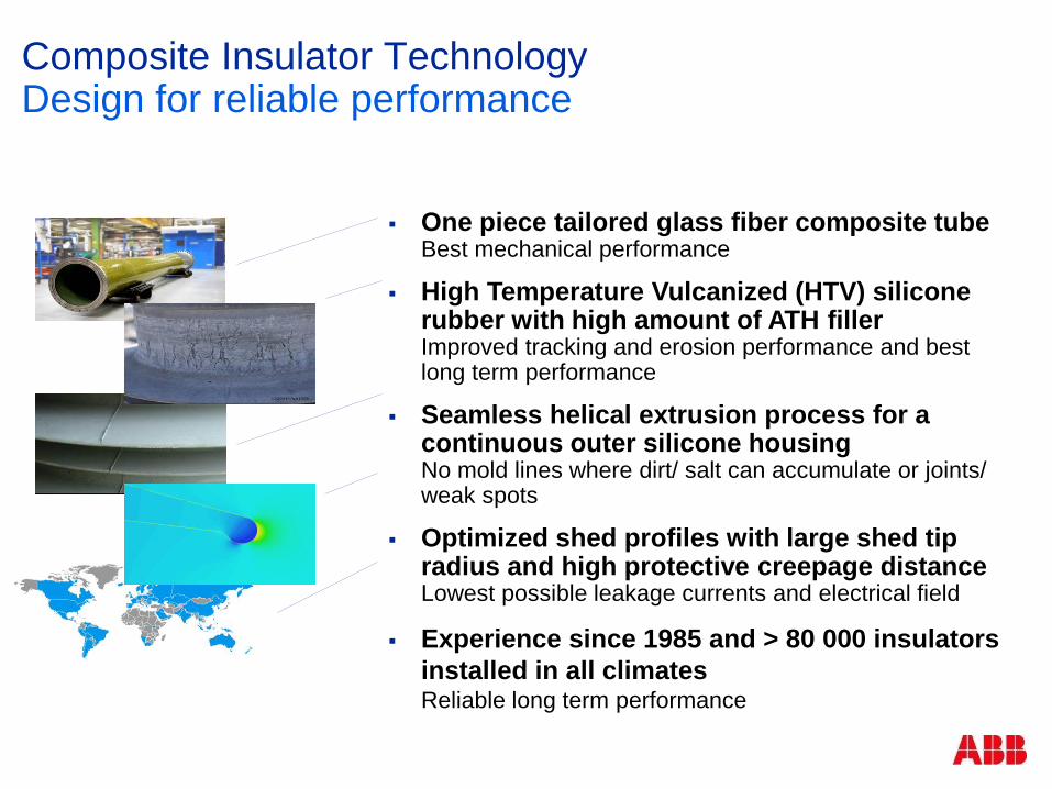
One piece tailored glass fiber composite tubeBest mechanical performance
High Temperature Vulcanized (HTV) silicone rubber with high amount of ATH fillerImproved tracking and erosion performance and best long term performance
Seamless helical extrusion process for a continuous outer silicone housingNo mold lines where dirt/ salt can accumulate or joints/ weak spots
Optimized shed profiles with large shed tip radius and high protective creepage distance Lowest possible leakage currents and electrical field
Experience since 1985 and > 80 000 insulators
installed in all climatesReliable long term performance
Composite Insulator TechnologyDesign for reliable performance

© ABB Group May 18, 2015 | Slide 80
Applying Mature Weather Shed TechnologyType O Plus DryTM

© ABB Group May 18, 2015 | Slide 81
Applying Mature Weather Shed TechnologyType O Plus DryTM
© ABB Group May 18, 2015 | Slide 82
Applying Mature Weather Shed TechnologyType O Plus DryTM
Recent Cigre paper concludes life of HTV
weather sheds good for life of bushing
(copies available).
This field study indicates “in service”
insulators in good condition under various
conditions.
Holding up well even in the most severe
environments.

1100 kV Oil-less wall bushings

600 kV DC Dry bushing.

© ABB Group May 18, 2015 | Slide 85
Applying Mature Weather Shed TechnologyType O Plus DryTM
No mold linesMold lines
Low electrical fieldHigh electrical field
Shed profile ≠ Shed profile
Injection
moldingHelical
extrusion

Short term storage of RIP/RIS bushings
Short term = less than one year
Store indoors in the original packaging materials
• Store where wildlife cannot
damage silicon sheds (rats,
birds etc.)

Longer term storage of RIP/RIS bushings
RIP condensers contain paper and are
machined to finished shape exposing paper
Store indoors away from direct sunlight
Store with silicon sheds not supporting
weight of bushing
Where wildlife cannot damage silicon
sheds (rats, birds etc.)
Must be stored in moisture tight bag or
metal tank over lower end and protected
from all moisture

Longer term storage of RIP/RIS bushings
RIS condensers contain no paper and are not
machined to finished shape
Store indoors away from direct sunlight
Store with silicon sheds not supporting weight of
bushing
Store where wildlife cannot damage silicon
sheds (rats, birds etc.)
Currently recommending moisture tight bag over
lower end

Permanent storage options

Permanent storage options

Wide range of applications

RIP applicable to bus duct installations

Development testing more intense
PD levels
Essentially none
Thermal testing
Specific to materials
Mechanical testing
To Fracture
CAT scans (void detection)
Dielectric testing
Extensive
Long term withstand
Proof of Altitude

New Routine testingType O Plus Dry™
Partial discharge:
Essentially background level of
facility (<5 pc) at 2xLG
Withstand extended (5 min.)
Leak tests:
No oil to leak from bushing
Test must ensure xfmr oil cannot
pass through bushing
Helium testing vac&press
Molded condenser verification:
Glass transition temp
Close SPC and chemical
verification

OIP has loss of life as insulation polymer chains
disintegrate, but this is function of time and temperature.
Dry bushings made with polymers, such as epoxy, are
much more sensitive to temperature for short times (like the
gaskets in OIP).
When the epoxy reaches glass transition temperature (Tg),
it begins to quickly turn into something(?) new and
dielectric performance is lost. No oil to fill voids. Damage
is irreversible.
Dry bushing Overload?
© ABB Group May 18, 2015 | Slide 96
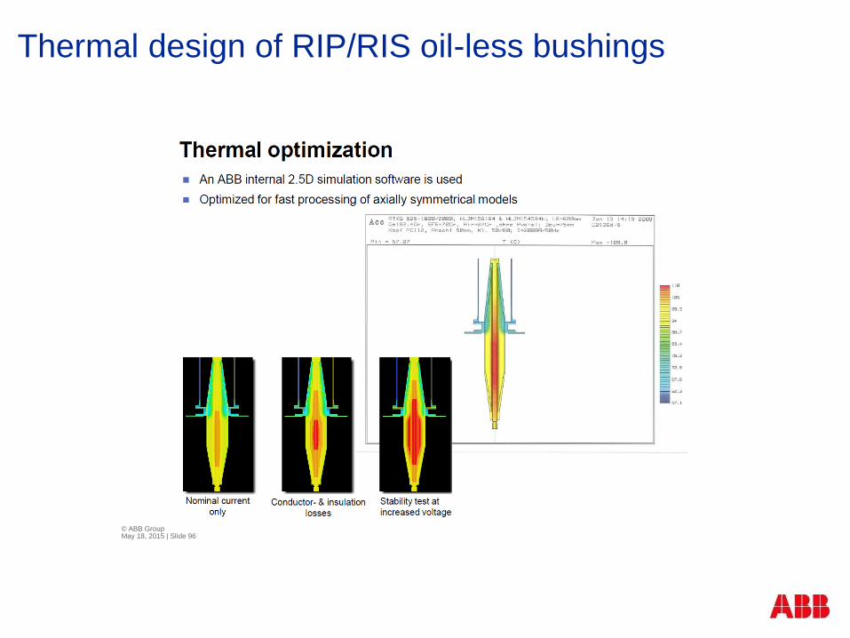
Thermal design of RIP/RIS oil-less bushings

Glass transition vs thermal rating
Tg?
The users does
not know the
thermal margin of
each design.

Thermal Conclusions.
Plan your overload need when you spec your bushings.
Remember that bushings rating rarely are at ratings of
transformer.
Relatively short excursions may compromise the
reliability of a bushing with no obvious evidence.
Be certain about bus/terminal temperatures &
connections
Dry bushing Overload?

Power Factor and Capacitance is still your best indicator
Capacitance increase indicates shorted layer
5% increase investigate and trend
10% remove from service
Power Factor increase indicates losses increase in
insulation
Thermal damage
Partial discharge in voids
50% investigate and trend
100% increase remove from service
Field assessment of RIP/RIS oil-less bushings

Power Factor and Capacitance is still your best indicator
Test before installation to match Name Plate
Test after installation to establish baseline
Test at 15 years in service
Test each five years thereafter
Test after long term storage
Thermal scan annually and after first loading
Visual inspection annually
Field assessment of RIP/RIS oil-less bushings

Monitoring devices are available
Power Factor
Capacitance
Partial Discharge
Lab testing can be performed if suspect:
AC
Withstand at 85% of original withstand with PD
Extended 1.5 X L-G with PD
Impulse
Lightning (1.5 X 50μs)
Switching surge at 85% original levels
Field assessment of RIP/RIS oil-less bushings
Technical limits of Dry
RIP lower ends absorb moisture
Hard limit for temperature
Order to Overload requirements
Vulnerable to rough handling

Your ABB Guardian Angel (or Transformer Troll?)
Michelin Man??
© ABB Group May 18, 2015 | Slide 104