Embed Size (px)
Citation preview

Transformer bushings, type GOH
Installation and maintenance guide
2750 515-85 en, Rev. 7, 2006-10-15

This document must not be copied without our written permission, and the
contents thereof must not be imparted to a third party nor be used for any
unauthoriszed purpose. Contravention will be prosecuted.

Safety informationKeep this instruction available to those responsible for the installation, maintenance,
and operation of the bushing.
The installation, operation, and maintenance of a bushing present numerous potential
unsafe conditions, including, but not limited to, the following:
High pressures
Lethal voltages
Moving machinery
Heavy components
Slip, stumble or fall
Specialized procedures and instructions are required and must be adhered to when
working on such apparatus. Failure to follow the instructions could result in severe
personal injury, death, and/or product or property damage.
Additionally, all applicable safety procedures such as regional or local safety rules and
regulations, safe working practices, and good judgement must be used by the
personnel when installing, operating, maintaining and/or disposing such equipment.
Safety, as defined in this instruction, involves two conditions:
1. Personal injury or death.
2. Product or property damage (includes damage to the bushing or other property,
and reduced bushing life).
Safety notations are intended to alert personnel of possible personal injury, death or
property damage. They have been inserted in the instructional text prior to the step in
which the condition is cited.
The safety conditions are headed by one of the three hazard intensity levels which are
defined as follows:
DANGER
Immediate hazard which will result in severe personal injury, death, or property
damage.
WARNING
Hazard or unsafe practice which could result in severe personal injury, death, or
property damage.
CAUTION: Hazard or unsafe practice which could result in minor personal injury, or
property damage.

4 2750 515-85 en, Rev. 7

52750 515-85 en, Rev. 7
Contents
1 Description ____________________________________________ 6
1.1 Design ________________________________________________ 6
1.2 Operating conditions _____________________________________ 9
1.3 Mechanical loading ______________________________________ 9
1.4 Spare parts _____________________________________________ 9
2 Installation _____________________________________________ 10
2.1 Tools _________________________________________________ 10
2.2 Consumables ___________________________________________ 10
2.3 Transport and handling ___________________________________ 10
2.4 Lifting from the box _____________________________________ 11
2.5 Mounting ______________________________________________ 11
2.5.1 Vertical mounting _______________________________________ 12
2.5.2 Horizontal mounting _____________________________________ 12
2.5.3 Inclined mounting _______________________________________ 12
2.5.4 Oil-filling without vacuum (inclined and horizontal mounting) ____ 13
2.5.5 Dismantling ____________________________________________ 13
2.5.6 Connections ____________________________________________ 13
2.6 Flange earthing _________________________________________ 15
2.7 Waiting time before energizing _____________________________ 15
2.8 Recommended tests before energizing _______________________ 16
2.8.1 Tightness test between transformer and bushing _______________ 16
2.8.2 Measurement of capacitance and tan δ _______________________ 16
2.8.3 Check of through resistance _______________________________ 18
3 Maintenance ___________________________________________ 19
3.1 Recommended maintenance and supervision __________________ 19
3.1.1 Cleaning of insulator surface _______________________________ 19
3.1.2 Measurement of capacitance and tan δ ______________________ 19
3.1.3 Thermovision (infrared camera) check for local overheating
on connectors ___________________________________________ 19
3.1.4 Check for leakage _______________________________________ 19
3.1.5 Checking and adjustment of the oil level _____________________ 20
3.2 Disposal after end of service life ____________________________ 20

6 2750 515-85 en, Rev. 7
1 Description
1 Description
1.1 Design
The GOH bushings are of the capacitance graded oil-impegnated paper type. The
conductor consists of a solid aluminium cylinder with cooling flanges at the oil side.
The design and dimensions of bushings type GOH are given in the Technical Guide,
1ZSE 2750-107. The design principle is also shown in Figs 1a-c. The air-side terminal
plates and the oil-side connections surfaces are, as standard, plated with a tin-zink
alloy, called firinite. Both sides of the terminal plates at the air-side, are plated and
can be used for connection. All GOH bushings are equipped with a test tap, see Figs.
2a-b, connected to the outer layer of the condenser body. The test tap can be used for
checking of the bushing insulation by capacitance and dissipation factor
measurements. The maximum test voltage for the test tap is 2 kV, one minute at 50 to
60 Hz. It serves as a test tap, and in connection with an external capacitance it can be
used as a voltage tap. The operation voltage is limited to 600 V. For connection of the
test cable an adapter, according to Fig. 3, should be used. An adapter is available for
permanent connection to measuring circuits, see Fig. 4.
goh_0001
11) Capacitance graded body
12) Sealing
13) Bottom plate
14) Guiding ring
15) Press ring
16) Locking ring
17) Spring device
18) Locking screws
19) Oil side terminal
and cooling flanges
20) Lifting eye
21) Radial sealing
Fig. 1a. Design principle
1) Outer terminal plates
2) Oil filling and venting plug M8,
2522 731-A
3) Expansion space
4) Oil
5) Porcelain insulator
6) Air side oil plug, M8, for separate
expansion tank, 2522 731-A
7) Mounting flange with one M12
threaded hole for earth connection
8) Test tap
9) Oil side plug, M8, for connection to
the transformer 2522 731-A
10) Porcelain insulator

72750 515-85 en, Rev. 7
1 Description
Fig. 1b. Previous design of sealing plug 2522 731-A.
1) Hexagon socket screw, 2121 738-4
2) Gasket, 2152 899-132
3) Conical spring washer, 2154 4004-3
Fig. 2b. Previous design of test tap 2769 518-A (self-earthing)
1) Cap nut, 2126 774-33
2) Gasket, 2152 795-5
3) Spring loaded earthing contact
4) Bushing, 2769 506-A
5) Mounting flange
6) Outer layer of condenser body
7) Threaded sleeve, 2129 702-2, 5/8" UNC
1325746
gob_0009
Fig. 1c. New design of sealing plug 2522 731-A.
1) Bolt with flange DIN 6921, 2121 738-18
2) Gasket, 2152 899-132
goh_0007
Fig. 2a. New design of test tap 2769 531-B (not self-earthing)
1) Bushing for test tap
2) Disc spring
3) Press nut
4) Cover 2749 528-B with O-ring 2152 484-2
5) Contact pin, 4 mm
6) O-ring
7) O-ring
8) Cable

8 2750 515-85 en, Rev. 7
Fig. 4a. New design of adapter for permanent
connection to measuring circuits 2769 531-D.
1) Cover
2) Box
3) Cable gland Pr (screwed steel conduit) 22.5
(Pg 16 acc. to DIN 40430)
4) Protecting resistor, 10 kW, 5 W
5) Earthing connection (to be removed
before connection of outer cable)
6) Nut
7) Belleville spring washer
8) Connector to test tap
9) O-ring
Fig. 3. Previous design of adapter for temporary
connection to test equipment 2643 762-A.
1) Clamp nut for test cable
2) Insulation sleeve
3) Barrel nut°�°�°������81&
goh_0008
gob_0003
3 2 1
1 Description
Fig. 4b. Previous design of adapter for permanent
connection to measuring circuits 2769 513-A.
1) Cover
2) Box
3) Cable gland Pr (screwed steel conduit) 22.5
(Pg 16 acc. to DIN 40430)
4) Protecting resistor, 10 kW, 5 W
5) Earthing connection (to be removed
before connection of outer cable)
6) Nut
7) Belleville spring washer
8) Connector to test tap
gob_0004

92750 515-85 en, Rev. 7
1.2 Operating conditions
The table below show the standard technical specifications for the GOH Oil - Air
bushings. For conditions exceeding the below values, please contact ABB.
Common specifications:
Application: Transformers
Classification: Oil impregnated paper, capacitance graded,
outdoor-immersed bushing
Ambient temperature: +40 to -40 °C, minimum value as per temperature
class 2 of IEC 60137 1
Altitude of site: < 1 000 m
Level of rain and humidity: 1-2 mm rain/min horizontally and vertically, as per
IEC 60060-1
Pollution level: According to specified creepage distance and
IEC 60815 2
Type of immersion medium: Transformer oil 1
Mounting angle: 0-45° from vertical or horizontal
Oil level below bushing flange: Maximum 25 mm
Max. pressure of medium: 100 kPa overpressure
Markings: Conforming to IEC/ IEEE
1 See Technical Guide, 1ZSE 2750-107, section Conductor loading.
2 IEC 60815 "Guide for the selection of insulators in respect of polluted conditions".
1.3 Mechanical loading
The bushings are designed for the following cantilever loads applied to the midpoint
of the top end terminal, perpendicularly to the bushing axis. The bushing mounting
angle can be 0-45° from vertical or horisontal.
Table 1. Mechanical loading
Bushing Type test load 1 minute (N) Max. service load (N)
GOH 170/10 10000 1500
GOH 170/16 10000 1500
GOH 170/25 10000 1500
1.4 Spare parts
In case of major damage to the bushing we recommend that it is sent back to ABB for
possible repair and re-testing. Certain parts (Figs. 1, 2, 8 and 9), which may be
damaged or lost during transport or installation, can be ordered from ABB.
1 Description

10 2750 515-85 en, Rev. 7
2 Installation
2 Installation
2.1 Tools
Soft slings
Torque wrench key for hexagon head screws, head width 18 mm (M12)
Key for hexagon socket head cap screw 6 mm. (Only for previous design of test
tap cover)
2.2 Consumables
Water free vaseline, Mobilgrease 28 or other lubricant not harmful to the trans-
former oil, to lubricate screws that come into contact with the transformer oil.
Mobilgrease 28 or other suitable grease to lubricate and protect the earthing
screw.
2.3 Transport and handling
CAUTION: The bushing shall be transported and stored vertically, with the top end
upwards. Keep the bushings dry and clean and protected against mechanical damage.
Keep the bushings protected from penetrating water when stored outdoors. This
means that the case must not be stored in areas where it can be foreseen that the
ground will be wet and muddy during heavy rains. Shelter the case from rain and
snow with a tarpaulin or roofing.
Carefully inspect the bushing on receiving with regard to shipping damage. Please
note that the bushing has been routine tested in oil and some oil may be left, especially
in the narrow opening between condenser body and flange.
The bushings are normally delivered from ABB in wooden boxes. The boxes are
marked with "Top End". All terminal contact surfaces are greased with vaseline before
delivery.
112750 515-85 en, Rev. 7
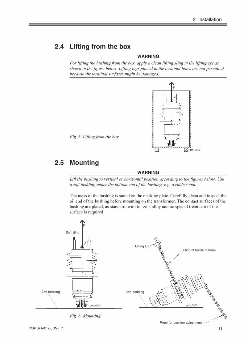
2.4 Lifting from the box
WARNING
For lifting the bushing from the box, apply a clean lifting sling in the lifting eye as
shown in the figure below. Lifting lugs placed in the terminal holes are not permitted
because the terminal surfaces might be damaged.
Fig. 5. Lifting from the box.
123456789012345678912345678901234567891234567890123456789123456789012345678912345678901234567891234567890123456789123456789012345678912345678901234567891234567890123456789123456789012345678912345678901234567891234567890123456789123456789012345678912345678901234567891234567890123456789123456789012345678912345678901234567891234567890123456789123456789012345678912345678901234567891234567890123456789123456789012345678912345678901234567891234567890123456789123456789012345678912345678901234567891234567890123456789123123123
121212 goh_0002
F
Fig. 6. Mounting.
Soft bedding
goh_0003
Sling of textile materialLifting lug
Soft bedding
goh_0002
2.5 Mounting
WARNING
Lift the bushing to vertical or horizontal position according to the figures below. Use
a soft bedding under the bottom end of the bushing, e.g. a rubber mat.
The mass of the bushing is stated on the marking plate. Carefully clean and inspect the
oil end of the bushing before mounting on the transformer. The contact surfaces of the
bushing are plated, as standard, with tin-zink alloy and no special treatment of the
surface is required.
F
Soft sling
Rope for position adjustment
2 Installation

12 2750 515-85 en, Rev. 7
2 Installation
2.5.1 Vertical mounting
If the bushing is vertically mounted the own expansion system of the bushing shall be
used. The sealing plug on the oil side (Fig. 8, Pos. 2) shall not be removed.
2.5.2 Horizontal mounting
If the bushing is horizontally mounted, the oil side plug at the flange (Fig. 8, Pos. 2)
shall be removed with the hole in the upward position in the transformer. The plug
shall be placed in the tapped hole at the flange edge.
At the oil filling of the transformer under vacuum, the bushing will be completely oil
filled and therefore no venting will be needed afterwards. The expansion of the
bushing oil will be taken care of by the main oil system of the transformer.
For filling without vacuum, see instruction below.
The sealing plugs on the
mounting flange shall be
turned upwards.
Fig. 7. Horisontal mounting.
2.5.3 Inclined mounting
The bushing can also be mounted up to 45o angle to the vertical. Larger angles may be
avoided as it is impossible to vent and fill the bushing without vacuum.
For inclined mounting the oil side plug (Fig. 8, Pos. 2) shall be removed and with the
hole in downward position in the transformer. The plug shall be placed in the tapped
hole at the flange edge. The hole in the top end plate is thus at the highest possible
position.
At the oil filling under vacuum the bushing will be completely oil filled and therefore
no venting is needed afterwards.
For filling without vacuum, see section 2.5.4.
goh_0004
Fig. 8. Opening at flange.
1) Sealing plug, air side, 2522 731-A
2) Sealing plug, oil side, 2522 731-A
3) Tapped storage hole for sealing plug
goh_0005

132750 515-85 en, Rev. 7
2.5.4 Oil-filling without vacuum
(inclined and horizontally mounted)
CAUTION: When the bushing is mounted more than 45° to the vertical it is not
permitted to fill without vacuum. The location of the venting holes makes it impossible
to vent the bushing at this inclination.
In cases when the transformer is not filled under vacuum (e.g. at exchange of bushing
at remote places) and the bushing oil system is connected to the main oil system of the
transformer, the following instructions are valid.
When the transformer has been filled with oil to the right level, the bushing must be
vented. A horizontally mounted bushing shall be vented by the hole on the air side of
the flange (Fig. 8, Pos. 1). For inclined up to 45° the bushing shall be vented by the
hole in the top end plate. When it is assured that the bushing is filled, the plug is
tightened.
2.5.5 Dismantling
Storing a bushing without expansion space could result in a high internal pressure. For
bushings mounted vertically no special precautionary measures are needed after
removal, because the bushing is completely closed. For bushings mounted horizontally
or inclined, the oil side hole at the flange (Fig. 8, Pos. 2) must be plugged after rem-
oval of the bushing. Then place the bushing vertically and adjust the oil level
according to Fig. 1 and Table 3. Correct expansion space is important to avoid high
excess pressure during storage and transportation.
2.5.6 Connections
CAUTION: Mounting of the conductors must be performed according to the
procedure below. The contact surfaces must be clean. The oxide on connected termin-
als is to be removed according to the instructions below. Failure to perform a proper
connection may result in overheating.
Do not use screw of stainless steel or screw with a coating at the oil side terminal.
For the long term stability, it is an advantage to limit the number of materials in the
contact. The GOH bushings have contact surfaces of aluminium with a coating of tin
and zinc. To get an optimal contact, use aluminium contacts with tin coating. It is not
recommended to use bare aluminium because the tin layer does not break through the
aluminium oxide. If bare aluminium is used, be sure to remove the oxide as described
below. Connections may also be made of copper or copper with tin coating. Silver
coating on aluminium or copper may also be used if the adhesion to the substrate can
be guaranteed in the actual environment.
Surface treatment method for uncoated surfaces: Use abrasive cloth, type scotch-brite
(brown) (first choice) or a steel brush. Apply contact grease (vaseline) on the entire
surface and rub (or brush) the surface in two directions until the entire surface has
been treated. Remove all the contemned grease and apply new contact grease on the
surface and remove the excess.
2 Installation

14 2750 515-85 en, Rev. 7
2 Installation
The GOH terminal is provided with many bolt holes for the connection to create a
number of distinct areas with defined and relatively high pressure. We recommend a
thickness of the opposite contact that is less than the radius of the plain washer. We
recommend a flatness deviation not exceeding 0.1 mm and a relatively high surface
roughness (Ra 6.3).
Electrical joint compound: For use at the air side we recommend penetrox A (Burndy)
or Nikkei S -200 or equal. For use at the terminal inside the transformer, we
recommend only unfilled vaseline.
The total contact pressure shall be at least 10 Newton/Ampere. For the M12 screws,
we recommend a tightening torque of 60 Nm. All screws shall be lubricated before
tightening. We recommend the use of a torque wrench. Use only grease not harmful to
the transformer oil.
The oil side terminal bolt holes are furnished with thread inserts the length of the
screw must be minimum 18 and maximum 30 mm below the contact surfaces, see
Fig. 9. Use only untreated black screw of steel (property class 8.8) at the oil side
terminal.
In order to maintain a sufficient permanent contact pressure, every screw at the termi-
nal shall be furnished with spring washers. At the air side, use spring washers on both
sides of the terminal plate. Every spring washer shall be placed on a flat washer with
larger diameter, see Fig. 9.
Fig. 9. Connections
a) Air side b) Oil side
1) Flexible connector
2) Terminal plate
3) Screw M12 or 1/2"
4) Nut
5) Flat washer 13 x 34 x 3
6) Spring washer 13 x 29 x 3 (34100 N)
7) Screw M12, K = min. 18, max. 30
goh_0006
Material combination in contacts
Aluminium (no plating)
Aluminium + tin plating
Aluminium + silver plating
Copper (no plating)
Copper + tin plating
Copper + silver plating
- Not recommended
++ Preferred choice
+ Good
+ Good
+ Good
+ Good
152750 515-85 en, Rev. 7
2.6 Flange earthing
The bushing flange is provided with a tapped hole M12. After tightening the bolts fixing
the bushing to the transformer tank, the flange should be earthed. This prevents
electrical discharges between bushing flange and transformer tank under normal
service conditions.
Alternative 1
Insert a heavily greased (Mobilgrease 28 recommended) pointed set screw M12
(stainless steel A4-80 preferrably). Tighten to 40 Nm, penetrating the paint of the
transformer tank down to the metal underneath. This makes an electrical connection
between the bushing and the transformer tank, keeping them at the same voltage.
Alternative 2
Apply a flexible cable between the M12 earthing hole in the bushing flange and a
corresponding connection point in the transformer. Grease the screw (Mobilgrease 28
recommended) and tighten the M12 in the bushing to 40 Nm. Connect the other end of
the cable to the transformer.
2.7 Waiting time before energizing
CAUTION: When a bushing has been stored horizontally, it must be raised with the
top up for at least 12 hours before service voltage is applied and 24 hours before test
voltage is applied. If, by mistake, the bushing has been stored horizontally more than
one year, it must be placed in the vertical position for at least one week before
energizing. Some waiting time may be necessary before energizing in order to avoid
flashovers or partial discharges due to airbubbles at the bushing surface. Choose a
suitable procedure below.
Vacuum filled transformer
No waiting time is necessary from the bushing point of view.
De-gassed oil-filled transformer
During mounting, use a clean and dry paintbrush to release surface bubbles. Wait 6
hours before energizing.
Gas-saturated oil-filled transformer
During mounting, use a clean and dry paintbrush to release surface bubbles. Wait 24
hours before energizing.
De-gassed oil filled transformer with reduced oil-level
After restoring the oil-level, wait 24 hours before energizing.
For all alternatives except vacuum-filled transformer, the oil should be allowed to enter
the centre tube to at least flange height by releasing the outer terminal sealing system
and allowing air to escape this way.
2 Installation

16 2750 515-85 en, Rev. 7
2 Installation
2.8 Recommended tests before energizing
The following tests may be performed to check the insulation, sealing and current path
of the bushing. The tests should be made after mounting, but before connecting the
outer terminal of the bushing to the rest of the switchyard power circuit.
1. Tightness test between transformer and bushing flange.
2. Measurement of capacitance and tan δ.
3. Check of through-resistance.
2.8.1 Tightness test between transformer and bushing flange
Several different methods may be used and we thus refer to instructions given by the
company responsible for the field erection. As a simple example, the tightness of the
seal between transformer and bushing flange may be checked when the transformer is
oil-filled by using chalk or, perhaps easier, with paper strips.
2.8.2 Measurement of capacitance and tan δδδδδWARNING
The new design of test tap is not self-earthing.
Since C2 usually is relatively small, the test tap must never be open-circuited when
applying a voltage to the bushing. It shall always be earthed or connected to an
external impedance. No connection may destroy the bushing.
CAUTION: When not measuring, always make sure that the cap nut is properly
tightened with the gasket in place. This is to prevent dust and water from coming in to
the test tap.
After mounting, a capacitance measurement is recommended. Connect a measuring
bridge between the outer terminal and the test tap by using a ø 4 mm lead coupler or
ABB's test tap adapter 2749 510-U. This is possible without removing the bushing as
the bushing has an insulated test tap, see Fig. 10. More details can be found in the
product information 2750 515-142, "Bushing diagnostics and conditioning".
Fig. 10a. New design of test tap 2769 531-B (not self-earthing)
goh_0009

172750 515-85 en, Rev. 7
With the transformer de-energized and the bushing outer terminal disconnected, the
test tap cover is removed. The measuring equipment is connected to the test tap and
the measuring voltage source to the bushing terminal.
The capacitances C1 between the centre tube and the tap, and the capacitance C
2,
between the test tap and earth are marked on the marking plate. The nominal
capacitances C1 of the different bushing types are listed in Table 2. C
2 is highly
dependent on the surrounding parts inside the transformer and it is not possible to give
a nominal value valid for all service conditions.
Table 2. Nominal capacitances in pF (Manufacturing tolerances for C1 ± 10%).
Type Catalogue No. Nominal capacitance (pF)
C1
C2
GOH 170/10 LF 126 007- 400 415
GOH 170/16 LF 126 008- 570 510
GOH 170/25 LF 126 009- 765 540
The dissipation factor varies with the temperature of the bushing body, and the
measured value should thus be multiplied with the correction factor (multiplier) given
in Table 3.
Table 3. Dissipation factor variations as a function of temperature.
Bushing body temperature °C Multiplier to 20 °C
3-7 0.85
8-12 0.90
13-17 0.95
18-22 1.00
23-27 1.05
28-32 1.10
33-37 1.15
38-42 1.20
43-47 1.25
48-52 1.30
2 Installation
Fig. 10b. Previous design of test tap 2769 518-A (self-earthing)
gob_0009

18 2750 515-85 en, Rev. 7
2 Installation
2.8.3 Check of through resistance
The through-resistance measurement method depends on the design of the trans-
former. Generally, a current is applied from bushing to bushing. The voltage drop
from outer terminal to outer terminal is measured. The resistance is calculated with
Ohm’s law, U = R·I. (U: Measured voltage drop. I: Through current. R: Total circuit
resistance.)
The total through resistance is the sum of the transformer winding and lead resistance
and the bushing conductor and contact resistance. The additional resistance from he
bushing conductor should not be more than 10 ... 100 mΩ. Since the through
resistance of the HV winding of a typical power transformer is in the order of
0.1 ..1 Ω, this is a very rough method that can only be used to detect very large faults
in the current path, such as disruptions.
Less-than-perfect contacts can only be detected by making a sensitive measurement
across each connection point, or by measuring the temperature increase during opera-
tion with an infrared sensitive camera (thermovision).

192750 515-85 en, Rev. 7
3 Maintenance
3 MaintenanceThe GOH bushings are maintenance-free.
DANGER
No work at all can be performed on the bushing while it is energised or not
earthed.
3.1 Recommended maintenance and supervision
1. Cleaning of insulator surface
2. Measurement of capacitance and tan δ
3. Thermovision (infrasred camera) check for local overheating on connectors
4. Check for leakage
5. Checking and adjustment of the oil level
3.1.1 Cleaning of insulator surface
CAUTION: Avoid having solvent on the bushing gaskets.
Under conditions of extreme pollution it may be necessary to clean the porcelain
insulator surface. This should be done by water-jet or by wiping with a moist cloth. If
necessary, ethyl-alcohol or ethyl-acetate may be used.
3.1.2 Measurement of capacitance and tan δδδδδPlease refer to Chapter 2 Installation.
3.1.3 Thermovision (infrared camera) check for local
overheating on connectors
At maximum rated current, the bushing outer terminal normally takes a temperature of
about 35 to 45 °C above the ambient air. Significantly higher temperatures, especially
at lower current loading, can be a sign of bad connections.
3.1.4 Check for leakage
Make a visual inspection for oil leakage during normal station supervision.

20 2750 515-85 en, Rev. 7
3 Maintenance
3.1.5 Checking and adjustment of the oil level
CAUTION: Oil sampling and dissolved gas in oil analysis.
Normally we do not recommend taking oil samples or opening our bushings. The
bushing is sealed and tightness tested at the time of manufacturing. An oil sampling
means that the bushing has to be opened. Thus, there is also a risk of improper
sealing after the sampling is finished. However, when a problem is known, for
example high power factor over C1 or visible leakage, there might be a need for oil
sampling and gas analysis or oil level check. In this case, ask for product information
2750 515-142 "Bushing diagnostics and conditioning".
The oil level in bushings may be checked through the oil filling hole at the top end. A
dry and clean dipstick should be used. In the hole there is a rubber plug. This plug
may be pressed down into the bushing so that checking of the oil level can be carried
out. Correct oil level is shown in Table 3. If the oil level is too high, oil can be sucked
out by means of a narrow hose. If the oil level is too low, clean and dry transformer oil
must be added. Adjustment of oil level is allowed only when the temperature of the
bushing is +5 °C to +35 °C. It is recommended that the sealing plug be provided with a
new gasket after the check. The sealing plug is to be tightened with 20 Nm. For
further information on oil sampling, see product information 2750 515-142.
For topping-up of the bushing, any clean and dry transformer oil available at site may
be used.
Table 3. Oil level for bushings without oil level gauge
Type Oil level at 20 ±10 °C, mm Oil level change
GOH Fig. 1 mm/10 °C *)
170/10 95 ±5 2.5
170/16 95 ±5 2.5
170/25 95 ±5 2.5
*) The bushing in vertical position.
3.2 Disposal after end of service life
The bushing consists of the following material:
- Conductor of low-alloy aluminium.
- Terminals of low-alloy aluminium plated with tin-zink.
- Transformer oil as per IEC 60296, class 2.
- Transformer oil impregnated condenser body consists of paper and 1 % Al foils.
- Spring device (rings) consist of Al alloys.
- Spring washers and cylindrical pins of steel.
- Previous design of test tap cap consists of plated brass. New design consists of
stainless steel.
- Insulators consist of quartz or alumino silicate based porcelain.

212750 515-85 en, Rev. 7


27
50
51
5-8
5 e
n, R
ev. 7
, 2
00
6-1
0-1
5
ABB Power Technologies ABComponentsVisiting address: Lyviksvägen 10Postal address: SE-771 80 Ludvika, SWEDENTel.+46 240 78 20 00Fax +46 240 121 57E-mail: [email protected]/electricalcomponents