Embed Size (px)
Citation preview

AARON 655 FM/ Rebroadcast Receiver
Installation & User Guide
www.inovonicsbroadcast.com


Installation & Operation User Guide
AARON 655
FM/ Rebroadcast Receiver
May, 2017 Firmware Rev. 1.0.0.0
Inovonics, Inc. 5805 Highway 9 Felton, CA 95018
Tel: (831) 458-0552 Fax: (831) 458-0554 Register online at www.inovonicsbroadcast.com
PRODUCT REGISTRATION RECORD
AARON 655 – Serial No. _____________
Purchase Date _____________________
Warranty Registered? Web
Reg. Date __________ By: ____________

HD Radio Technology is manufactured under license from iBiquity Digital Corporation. U.S. and Foreign Patents apply. For patents see http://patents.dts.com/. HD Radio and the HD, HD Radio and “ARC” logos are registered trademarks of iBiquity Digital Corporation in the United States and/or other countries.

— 3 —
TABLE OF CONTENTS
Section I – INTRODUCTION AARON 655 PRODUCT DESCRIPTION .......................................... 7
Features
AARON 655 TECHNICAL SPECIFICATIONS .................................. 8 General Performance Inputs & Outputs Failover Audio Protection Audio Processing RDS/RBDS Encoder BandScanner™ Alarms and Logs Miscellaneous
BLOCK DIAGRAM ............................................................................ 9
Section II – INSTALLATION GENERAL ........................................................................................ 11 UNPACKING AND INSPECTION .................................................... 11 MOUNTING ..................................................................................... 11
Rack Requirement Heat Dissipation
AC (MAINS) POWER ....................................................................... 12 RADIO FREQUENCY INTERFERENCE (RFI) ................................ 12
Location Ground Loops
ANTENNA INPUT ............................................................................ 12 PROGRAM LINE INPUTS ............................................................... 13
Analog Line Input Unbalanced Operation AES Digital Line Input
PROGRAM LINE OUTPUTS ........................................................... 13 Analog Line Outputs Unbalanced Operation AES Digital Line Output
COMPOSITE/MPX OUTPUT ........................................................... 14 NETWORK PORT ............................................................................ 14 GPIOs .............................................................................................. 14

— 4 —
Section III – SETUP AND OPERATION NAVIGATING THE MENUS ............................................................ 15
Graphic Display ‘VU’ Meters Local Alarms The Jog-Wheel Knob The Back Button Menu Timeout and Screensaver
THE AARON 655 MENU TREE ....................................................... 16 AARON 655 READOUTS AND METERING ................................... 17
The Now-Playing Screen Program Source Selection Backup Sources and ‘Failover’
SETTING UP THE RADIO .............................................................. 19 Tuning and Program Selection Radio Audio Levels Radio Audio Loss Alarm Radio Low Signal Alarm RDS Error Alarm Pilot Loss Alarm HD Loss Alarm Radio Settings RDS Info HD Info BandScanner™
ANALOG & DIGITAL LINE-SETUP ................................................ 22 STREAMED PROGRAM SOURCES ............................................. 22 THE AUDIO PROCESSOR ............................................................ 23
Metering Processing Presets Setting Input Levels AGC Leveling Equalization Multiband Processing Crossovers ‘Master’ and Band Drives Band Uncoupling Bass Punch Limiting WB Release HF Limiting and Clipping Composite Clipping Processor Bypass Test Oscillator

— 5 —
DAYPARTING ................................................................................. 27 THE FM STEREO GENERATOR ................................................... 27
Pre-Emphasis Transmission Mode Multiplex Output
THE RDS ENCODER ..................................................................... 29 Subcarrier Injection Static RDS Data Entry Options Scrolling Speed Alternative Frequencies HD to RDS Streaming to RDS Telnet
PROGRAM LINE OUTPUTS .......................................................... 31 NETWORK SETUP .......................................................................... 31
DHCP IP Assignment Manual IP Setup Assigning a Hostname Remote Access Dynamic DNS Timekeeping Setup Network Status
SNMP OPERATION ....................................................................... 33 SNMP Overview SNMP Mode SNMP Security SNMP Ports SNMP Traps
ALARMS AND NOTIFICATIONS ..................................................... 34 Alarm ‘Tallies’ Email & Text Notifications SMTP Setup Alarm Log Settings
MISCELLANEOUS SETTINGS ........................................................ 36 Passwords Lost Password (Hard Reset) Display Settings About Headphone Volume

— 6 —
Section IV – THE WEB INTERFACE GENERAL ....................................................................................... 38 CONNECTING TO THE AARON 655 ............................................... 38 THE WEB INTERFACE PAGES ...................................................... 39
Remote Listening ‘VU’ Meter
THE MENU LIST ............................................................................. 40 Tuning the Radio Inputs Outputs Audio Processing RDS Encoder Alarms Network Settings Downloading the MIB File Admin Settings
THE HARDWARE PROFILE ........................................................... 41 UPDATING FIRMWARE .................................................................. 42
APPENDIX INOVONICS WARRANTY ................................. (INSIDE BACK COVER)

— 7 —
Section I
INTRODUCTION
AARON 655 PRODUCT DESCRIPTION
Inovonics’ AARON 655 is a professional-grade FM and FM/HD-Radio™ rebroadcast receiver.
Although a primary application for the AARON 655 is FM ‘translator’ service, this receiver finds use in other program-origination and audio processing situations.
Features Leading features of the Inovonics AARON 655:
All-digital “SDR” (Software-Defined Radio) off-air re-ception of analog-FM and HD Radio programs HD1-HD8.
Accepts off-air program sources, plus streamed con-tent and analog L/R and AES digital program feeds.
Automatic failover program backup sequences to mul-tiple alternate program sources.
Built-in scheduler for dayparting.
Comprehensive and versatile multiband audio pro-cessing for all sources with both factory-defined and user-programmable processing presets.
Intuitive, menu-driven front-panel setup, plus a built-in Web server for full remote operation over any IP net-work. Supports dynamic DNS and SNMP remote moni-toring.
Local, remote and self-logging alarms for audio loss in all modes, plus RF loss, RDS error or ‘hijacking’, stereo pilot loss and HD Radio carrier loss. Alarms include email or text-message notification.
A BandScanner™ utility gives a spectrum plot of the entire FM band or a specific portion.
The AARON 655 boots or resets in less than one second and draws only 12 watts from the AC mains.

— 8 —
AARON 655 TECHNICAL SPECIFICATIONS
Certain technical specs of the AARON 655 are either difficult to quantify in tabular form, or they do not adequately reflect overall performance in a real-world broadcasting situation. Manual text further explains features and performance aspects in appropriate sections of the text.
GENERAL PERFORMANCE Tuning Range: 87.5MHz-107.9MHz in
100kHz steps Sensitivity/Noise Performance: 5dBuV for
50dB unweighted, monaural analog-FM SNR
Off-Air Frequency Response: Analog FM: 20Hz-15kHz, ±0.5dB HD Radio: 20Hz-20kHz (per certification
spec.) FM De-emphasis: 75µs or 50µs, menu-
selectable Stereo Separation (at 1kHz):
Analog FM: >50dB HD Radio: >90dB Line-In Sources: >120dB
Radio Data System: Analog FM: RDS/RBDS, menu-selectable HD Radio: “PAD”
Program Signal Latency (Delay): Analog FM or Line-In Sources: 3.7ms to
analog line out, 4.53ms to digital line out, 4.1ms to MPX out
HD Radio Source: Subject to typical 8 se-cond program path delay
INPUTS & OUTPUTS Antenna Input: 50-ohm ‘N’ Composite/MPX Output: Unbalanced 75-
ohm (BNC), 1V p-p to 6V p-p for ±75kHz FM carrier deviation
Program Line Inputs: Analog: Active-balanced (XLR) accepts
‘0VU’ line levels between –15dBu and +15dBu; +24dBu clipping
AES Digital: Balanced (XLR) accepts peak line levels between –30dBFS and 0dBFS at sampling rates between 32kHz and 96kHz
IP Streaming: Accepts Icecast/SHOUTcast MP3, Ogg and AAC streams
Program Line Outputs: Characteristic: Analog and digital pro-
gram line outputs may be switched be-tween FM-pre-emphasized or FM ‘nor-malized’ (flat) response
Analog: Active-balanced (XLR) delivers –12dBu to +18dBu at 100% modulation; +18dBu clipping; 200-ohm source
AES Digital: (XLR) 24-bit, 44.1kHz sam-pling; delivers –30dBFS to 0dBFS at 100% modulation
Streaming: MP3-encoded for remote IP/browser monitoring
Network Port: RJ45 jack TCP/IP network connection for remote setup and opera-tion; supports SNMP
GPIO: 4 GPI, 6 GPO screw-terminal connec-tions, menu-assignable with selectable logic polarity
Headphone Jack: ¼-inch front-panel (TRS)
FAILOVER AUDIO PROTECTION Four progressive (sequential) failovers may be selectively programmed to respond to au-dio loss, carrier loss, FM pilot loss, HD carrier loss or RDS mismatch as appropriate to the source fault
AUDIO PROCESSING AGC: Gated, ‘gain-riding’ AGC with ±15dB
capture range; dual-rate ‘windowed’ opera-tion
Leveling: Variable ‘syllabic’ 2:1 compression normalizes dialog and music sources
Parametric EQ: 4 sections with variable fre-quency, ‘Q’ and gain
Bass ‘Punch’: Variable bass-attack enhancement
Compression: 3 band r.m.s./peak compres-sion with selectable crossovers; variable master and band drive controls
Final Peak Control: Feed-forward final peak limiting; independent HF limiter for FM
Composite Clipper: 0dB-3dB clipping depth Processing Presets: 10 factory, 10 user-
defined

— 9 —
RDS/RBDS ENCODER Fields Supported: PI, PTY, PS, RT, M/S, TP,
DI, CT, AF HD ‘PAD’ to RDS: HD Radio Name, Slogan,
Artist, Title, Album and Genre may be converted to the RDS scrolling-PS and RT fields
Streaming Audio Metadata to RDS: Streamed Name, Metadata, Description and Genre may be converted to the scroll-ing-PS and RT fields
Telnet to RDS: Accepts dynamic PS and RadioText updates via IP; connect with station automation
BANDSCANNER™ An internal spectrum analyzer utility sweeps the entire FM band (or a selected portion) and presents a graphic display of all signals re-ceived, including RSSI values and HD Radio transmission identification
ALARMS AND LOGS Alarms: Fault alarms include radio audio
loss, analog line-in audio loss, digital line-in audio loss, stream audio loss, low sig-nal, RDS loss/error, stereo pilot loss and HD Radio channel loss. Alarms trigger front-panel indicators, local (GPO) clo-sures, browser interface notations, SMS-text/email dispatches, SNMP
Alarm Logs: Alarms are logged and may be downloaded as daily, weekly or monthly CSV files
SNMP: All setup and operating controls and alarm functions are under SNMP manage-ment
MISCELLANEOUS Internal Test Tone Generator: 20Hz-20kHz;
30dB attenuator Power Requirement: 88VAC-264VAC, 48Hz-
63Hz; (‘universal’); 12W. Operating Environment: 32°F/0°C-
122°F/50°C; 0% - 95% non-condensing relative humidity; 10,000ft/3048m
Conformances:
EN50081-1 EN50082-1 93/68/EEC
2002/95/EC
BLOCK DIAGRAM
As a rebroadcast receiver, the AARON 655 incorporates a Software-Defined Radio (SDR), and including all other elements of its design is almost entire-ly DSP-based. Virtually all its functionality is provided through firmware coding. The Block Diagram presented on the following page illustrates product basics, but has been deliberately organized as if the AARON 655 were instead a perhaps more familiar analog design. This should give the reader a more understandable functional representation of the product, although the actual signal path deviates appreciably from what’s shown.

— 10 —

— 11 —
Section II
INSTALLATION
GENERAL
This section of the manual addresses the physical installation of the AARON 655 at its operating location, the ‘nuts and bolts’ of connecting the unit. This section also references pages where pertinent setup adjustments are discussed.
UNPACKING AND INSPECTION
As soon as the equipment is received, inspect carefully for any shipping damage. If damage is found or suspected, notify the carrier at once, and then contact Inovonics.
We recommend that you retain the original shipping carton and packing materials for return or transshipment if necessary. If returned for Warranty repair, shipping damage sustained as a result of improper packing for return may invalidate the War-ranty!
IT IS IMPORTANT to register the Warranty of your AARON 655. This assures coverage of the equipment under terms of the Warranty, provides a means of tracing lost or stolen gear, and adds the user to a database to receive specific service instruc-tions or software/firmware updates when issued. Register online at: www.inovonicsbroadcast.com/product registration.
NOTE: Many users choose first to familiarize themselves with equipment on the bench or at their desk, in which case they may immediately turn to Section III that describes AARON 655 setup and use. When the time comes, do please refer back to this section to confirm proper physical installation and inter-connection with other station equipment.
MOUNTING
Rack Requirement
The AARON 655 mounts in a standard 19-inch equipment rack and requires only 1¾ inches (1U) of vertical rack space. We recommend using plastic or fiber washers to protect the paint-ed finish around the mounting holes.
Heat Dissipation Consuming miniscule energy that belies its powerful perfor-mance, the AARON 655 itself generates negligible heat, thus it has no noisy internal fan and bothersome filter to change or

— 12 —
wash. The unit is specified for operation within an ambient temperature range between freezing and 120°F/50°C. Because adjacent gear may radiate substantial heat, be sure that the equipment rack is adequately ventilated to keep internal tem-perature below the specified maximum ambient.
AC (MAINS) POWER
The AARON 655 has an internal ‘universal’ switching power supply that accommodates main voltages between 88VAC and 264VAC. Self-protection circuits obviate the need for an exter-nal fuse.
The detachable IEC-type power cord supplied with the product is fitted with a North-American-standard male plug. If you need to replace the mains plug with another, you will find that the individual cord conductors are color-coded in one of two ways. US standards specify black for AC ‘hot,’ white for AC neutral and green for earth ground. European CEE standards specify brown for AC ‘hot,’ blue for AC neutral and green with a yellow stripe for earth ground. Please keep these straight.
RADIO FREQUENCY INTERFERENCE (RFI)
Location Although it is expected that the AARON 655 will be co-located with FM transmission equipment, do practice care and common sense in locating the unit away from abnormally high RF fields.
Ground Loops Because the unbalanced composite/MPX output of the AARON 655 is referenced to chassis ground, a mains frequency or RF ground loop could be formed between cable shield grounds and the AC power cord ground. A ‘ground-lifting’ AC adapter may remedy such a situation, although the chassis must somehow be returned to earth ground for safety. Generally, being screwed-down in the equipment rack will satisfy the safety re-quirement.
ANTENNA INPUT
The rear-panel ANTENNA connector is a 50-ohm ‘N’ input to the receiver. An ‘N’ to ‘F’ adapter is supplied, and adapters to other connector types are readily available.
Many factors will guide your selection of an antenna, not the least of which is the level and purity of the off-air signal. Alt-hough the selectivity of the AARON 655 is remarkably good, it’s not impossible that a band-pass or band-stop filter may be re-quired for situations where the receiver is co-located with high power transmitters.

— 13 —
PROGRAM LINE INPUTS
Analog Line Inputs
Left- and right-channel ANALOG INPUTS are high-impedance ‘bridging’ and electronically-balanced. Under the Set-up/Inputs/Analog Input/Analog Input Level menu these may be ad-justed for “0-VU” program levels between –15dBu and +15dBu.
Unbalanced Operation
The AARON 655 is able to accept low-level, unbalanced con-sumer-grade inputs if necessary. Connect the center conductor of the shielded input lead to Pin 2 of the XLR connector. Split the shield and connect it to both Pin 1 and Pin 3.
AES Digital Line Input
The AES DIGITAL INPUT is a balanced, transformer-coupled dig-ital stereo program input conforming to AES3 specifications. This 16/24-bit input accommodates sampling rates between 32kHz and 96kHz. Under Setup/Inputs/Digital Input/Digital Input Level, gain may be set for program feeds with peak levels that range between –30dBFS and 0dBFS.
PROGRAM LINE OUTPUTS
AARON 655 digital and analog line outputs are available simul-taneously, each with its independent settings.
Analog Line Outputs
Male XLR left- and right-channel ANALOG OUTPUTS on the rear panel are electronically-balanced. This means that they are ground-referenced and not transformer-isolated.
Under the Setup/Outputs/Analog Audio Output menu, analog line outputs may be adjusted to any level between –12dBu and +18dBu, corresponding to 100% modulation. The dB levels shown below the slider control represent the unloaded output level. These outputs have a resistive source impedance of 200 ohms. Feeding a 600-ohm load will drop the actual dBm level 2.5dB below the Analog Level shown under the slider.
This menu also sets the output characteristic. FM-Pre imparts the 50µs or 75µ pre-emphasis curve to the output signal. FM-Flat is a ‘normalized’ output with a flat frequency response, yet it conforms to the overload limits of the pre-emphasis curve. Your selection will depend on whether an exciter fed by the AARON 655 requires a pre-emphasized feed or has internal pre-emphasis.
Unbalanced Operation
If the analog line outputs of the AARON 655 are connected to low-level, unbalanced inputs of consumer-grade equipment, connect the center conductor of the shielded output lead to Pin 2 of the XLR connector and the shield to Pin 1. Leave Pin 3 un-connected.
Driving unbalanced lines, the actual output level will be 6dB lower than the Analog Level shown in the Analog Audio Output menu, as only one side of the bridge-configuration output stage is being used.
— 14 —
AES Digital Line Output
The male XLR connector labeled AES DIGITAL OUTPUT is a bal-anced, transformer-coupled digital AES3 stereo program out-put. This is a 24-bit output at the 44.1kHz sampling rate com-mon to HD Radio plant practices.
The digital output level is set on the Setup/Outputs/Digital Audio Output menu. The dB notation below the slider control corre-sponds to the level of program peaks at 100% modulation (±75kHz carrier deviation), adjustable between 0dBFS and –30dBFS.
Just as described above for the Analog Line Output, an FM-Pre (pre-emphasized) or an FM-Flat output characteristic may be se-lected here.
COMPOSITE/MPX OUTPUT
MPX OUT is an unbalanced BNC composite/MPX source at a 75-ohm impedance. The level is adjusted under the Setup/Outputs/ Stereo Generator/Multiplex Out menu, and the open-circuit (unload-ed) peak-to-peak voltage is indicated below the slider. This can be adjusted between 1V p-p and 6V p-p, corresponding to ±75kHz carrier deviation.
The S+S’ component of the composite/MPX signal may optional-ly be subjected to a selected degree of composite clipping (see Page 27).
NETWORK PORT
A standard RJ-45 network jack is used to connect the AARON 655 to a Local Area Network (LAN) or to the Internet. Network-ing permits full remote control and input/output audio stream-ing, plus full SNMP functionality. Networking setup is ex-plained starting on Page 31.
GPIOs
A removable screw-terminal strip on the rear panel gives access to four GPI (General-Purpose Input) and six GPO (General-Purpose Output) terminals. GPOs may be assigned to reception and other fault alarms; their programming is detailed under Alarm ‘Tallies’ on Page 34. GPIs are thoughtfully included for fu-ture applications.

— 15 —
Section III
SETUP AND OPERATION
For most of its functionality, the AARON 655 may be placed in service either through local, front-panel setup or by using the Web interface, admittedly a quicker and easier option. Never-theless, despite our having become adept at pointing and click-ing, some familiarity with the jog-wheel knob and menu tree is encouraged, as you’ll need to gather information from the front panel anyhow before you can point your browser at the AARON 655 Webpages.
NOTE: Some setup items with just a mention in this section will be detailed in the next, which assumes connection to a network and deals exclusively with those procedures involving network applications of the AARON 655.
‘Boot’ (startup) time of AARON 655 is about one second. When AC power is first applied, or following a power interruption, the unit is back in full operation almost immediately. Setup and reception parameters in use previous to the power glitch are re-loaded instantly from non-volatile memory into the processing core.
NAVIGATING THE MENUS
All setup and operating adjustments of the AARON 655 are un-der firmware control. There are no jumpers, switches or me-chanical potentiometers, only the front-panel jog-wheel knob A and Back button B identified in the illustration.
E D C B A Graphic Display
The OLED graphic display screen C presents the intuitive setup menu tree in an easy-to-follow format. The display uses a screen saver, so if the screen goes dim or dark, simply push the jog-wheel knob or Back button once to bring it back to life. No selection or change is made with this ‘wake-up call.’
‘VU’ Meters LED-segment meters D are peak-responding and have nonlinear scaling to optimize range and resolution. These meters bridge the input of the AARON 655 audio processing section.

— 16 —
Because it is peak- rather than VU-responding, this metering has a built-in offset based on an approximate 10dB ‘crest fac-tor’ (average/peak ratio) of typical program material. Hence the use of actual program material for level-setting is preferred to tests using steady-state sinewave tones
Local Alarms Four front-panel LEDs E give immediate indication of critical reception errors, HD Radio digital-lock and HD multicasting.
The Jog-Wheel Knob
Turn the jog-wheel knob to cycle among highlighted menu items, and then push it to select or adjust the highlighted item. There may be multiple menu levels for the item you need to reach. Once you do reach a submenu that allows control over a function, you turn the knob to position brackets around the ad-justable function, push it once more to make a selection or to gain control of an adjustable parameter.
After dialing-in a specific ‘incremental’ value (audio level, alarm threshold, etc.), it’s a good idea to push the knob a final time to commit that value to memory. If you dawdle, or simply walk away, after 30 seconds of no further knob activity the AARON 655 will assume that the new setting is what you want and will enter it into memory automatically as the screen is ‘deselected.’
The Back Button The Back button will always return you to the previous menu screen. Push it repeatedly to go back to the Main Menu.
If you make a mistake (for example, you might push the knob slightly off-center, which could also rotate the knob and bring up the wrong menu), simply push the Back button to return to the previous menu and try again.
Menu Timeout and Screensaver
After making and saving a setting, you may press the Back but-ton to return to the Main Menu screen, or simply leave any cur-rent screen showing. After 30 seconds, the current screen will ‘deselect,’ and the knob will no longer respond to an adjust-ment command without reselecting that screen.
After a programmed interval (see Display Settings on Page 37) the screen will either dim or go dark to help prolong the life of the OLED display. At any time, however you can press the jog-wheel knob or Back button to bring the menu back up.
THE AARON 655 MENU TREE
The several levels of front-panel setup and operating menus are laid out in an intuitive and easy-to-manage fashion. The com-plete Menu Tree is shown and explained below.
Menu Titles are shown here in a font similar to the OLED display font. Main Menu items are against the left margin, submenu levels are indented appropriately.
‘Action’ menu levels will indicate whether that menu level is a readout (display) of some parameter, or if it accepts some form of

— 17 —
user entry. (set) generally signifies an on/off or enable/disable function, and (select) denotes user control over multiple or mul-tiple-choice selections, or adjusting some value in very small increments. (data entry) calls for alphanumeric character entry in-to data fields. Data entry is cumbersome with the jog-wheel knob and is much more easily done through the Web interface.
AARON 655 FRONT-PANEL MENU TREE Now Playing (display) Input Sources Primary Source Audio (select) RDS: (select) Triggers to Next Source: (select) Backup Source 1-3 (same setup as Primary) Processor Meters (display) Presets (select) AGC & Leveling (display & set) Parametric EQ EQ Enable (select) EQ Parameters (set & display) Multiband Bass Punch (set) Band Drive (display & set) Band Uncoupling (set & display) Crossovers (set) Limiting Tri-Drive & RMS/Peak (display & set) Final Limiter (display & set) MPX Clipping (set) Daypart (select) Bypass (select) Test Oscillator (select and set) Setup Inputs Radio Tuner (select & display) Radio Audio Input (display & set) Radio Alarms Radio Audio Loss (set) Low Signal (select & set) RDS Error (select & set) Pilot Loss (select & set) HD Loss (select & set) Radio Settings RDS/RBDS (select) FM Blend Mode (select) RDS Info Decoded RDS (display) Radio Text Plus (display) RDS Groups (display) Alternative Freqs (display) Open Data Apps (display)
(Setup/Inputs/Radio—continued) HD Info HD SIS (display) HD PSD (display) BandScanner (set & display) Analog Input Analog Input Level (display & set) Analog Audio Loss (set) Digital Input Digital Input Level (display & set) Digital Audio Loss (set) Stream Input Stream URL (data entry & select) Stream Info (display) Stream Input Level (display & set) Stream Audio Loss (set) General Purpose Inputs (select) Outputs Stereo Generator Pre-Emphasis (select) Stereo/Mono Mode (select) Pilot Injection (set) Multiplex Out (set) RDS Encoder RDS Injection (set) RDS Data (set) RDS Options (select) PS Scroll Speed (set) AF List (data entry) HD to RDS HD DPS (data entry) HD Radio Text (data entry) Stream to RDS Stream DPS (data entry) Stream Radio Text (data entry) Telnet (select & set) Analog Audio Output (set & select) Digital Audio Output (set & select) General Purpose Outputs (select) Network IP Settings (display & set) Hostname (data entry) Dynamic DNS (set & data entry) Time Time Zone & DST (select)

— 18 —
(Setup/Network/Time—continued) Time Server (data entry) SNMP Mode & Communities (select) SNMP Ports (data entry) Trap Destinations (data entry) Status (display) Email Preferences SMTP Server (data entry & select) Sender (data entry) Recipients (select & data entry) Send Test Email (select)
Alarms & Notifications Email Notifications (select) Alarm Log Settings (select) Alarm Log (display) Admin Security (data entry) Display (set & select) About (display) Headphones (set & select)
AARON 655 READOUTS AND METERING
The AARON 655 offers an array of OLED and Web interface me-ters and data readouts useful for setup and for monitoring in-coming and outgoing signal parameters. The front-panel OLED display offers exceptional resolution for a 1U presentation, and the Web interface echoes the same information in similar syn-tax on any PC, tablet or mobile phone with network access.
The Now-Playing Screen
Now Playing is at the top of the Main Menu. The display will al-ways give particulars associated with the program source cur-rently selected. The upper example here shows an off-air HD2 program source, with HD2 for the audio pro-gram and RDS data convert-ed from the HD2 PAD in-formation. The second ex-ample shows an analog line input for audio and internal-ly-generated, static entries in the PS and RT fields.
Other screens will be shown and discussed as they come up in the discussion of AARON 655 setup and use.
Program Source Selection
The Input Sources menu not only lets you select what goes out over the air as pro-gram audio and metadata, but also what ‘failover’ op-tions you may choose.
Primary Source is the default, initial ‘go-to’ source for the rebroadcast signal. This is the first selection under Input Sources. In this example, we have selected Radio as the audio source (actually HD2 program audio in this case) and are reconfiguring HD PAD data from the HD2 broadcast into the RDS data format for rebroadcast. Here

— 19 —
we have optionally elected to use Radio Audio Loss as a ‘trigger’ for the AARON 655 to ‘failover’ to Backup Source 1.
Backup Sources and ‘Failover’
In our example here, Backup Source 1 has been program-med to replace off-air radio audio with the Analog line input when Primary Source radio audio is lost, and to replace the incoming HD PAD con-version with static Internal messaging. Backup Source 1 can, in turn, be set to trigger a second backup, and so-on.
Whenever a higher-priority source returns and its alarm resets, the AARON 655 will automatically go back and reestablish that source as the on-air feed.
SETTING UP THE RADIO
Tuning and Program
Selection
The Setup/Inputs/Radio/Tuner screen displays the r eceive frequency, and how many HD Radio program channels are available. Here you can bracket either the frequency or the program selection box to choose a station and program channel (FM, HD1, HD2, etc.) for rebroadcast. The readouts on the right are a display of recep-tion parameters, including the incoming signal level RSSI in dBµV, and DQ, a relative ‘robustness’ percentage figure for the HD Radio signal, if applicable.
NOTE: When the AARON 655 is tuned to an HD Radio broad-cast and the digital signal is lost, the receiver does not revert to analog-FM reception. The selection box at the bottom of the display sets the reception mode between FM and HD1 through HD8. This selection is ‘global’ and will determine the single off-air channel that will be received.
Radio Audio Level
The Setup/Inputs/Radio/Radio Audio Input menu includes a bargraph presentation of the off-air audio levels. A float-ing peak-hold segment and numerical readout lends further accuracy to the measurement. Input Level is a trim adjustment with a ±15dB range. Generally, a 0.0dB setting here will be close to optimum if the incoming carrier is properly modulated.
Keep in mind that FM and HD1 channels are traditionally modu-lated quite aggressively in deference to the questionable con-cept of ‘market domination’ couched in a loudness-war mentali-ty. An aggressively-processed program may call for a –3dB In-put Level setting, while a modestly-processed HD2 or HD3
— 20 —
channel may suggest as much as several dB of gain here. Refer to Setting Input Levels on Page 24.
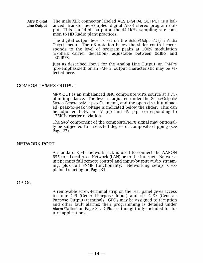
Radio Audio Loss Alarm
The Setup/Inputs/Radio/Radio Audio Loss screen is typical of AARON 655 setup for any audio-loss alarm. Setup will be de-tailed here and serve as a tutorial for all rebroadcast sources.
The Alarm checkbox simp-ly ‘arms’ the alarm. If this box is not checked, there will be no alarm indication by the front-panel AUDIO LOSS LED or the corresponding indicator on the Web interface Now Playing screen. Also there will be no closure at a rear-panel GPO terminal, nor will the AARON 655 send SMS/text or Email alerts to station personnel. Moreover, if failover to a secondary program feed depends on radio audio loss, that function will be inhibited as well. In short, the Alarm box must be checked for any audio-loss (or other) alarm to activate.
Threshold On and Threshold Off windows display the current level of the off-air program audio as a dim bargraph. Threshold On is the set point that the program must go below to trigger an alarm and must remain below this set point for the number of seconds programmed into in the Time On window. For the alarm to reset, the program level must re-attain the Threshold Off value and remain above that point for the number of seconds set in the Time Off window. In this example, the program must fall below –25dB for a full 15 seconds to give an alarm. Then when the program returns, it must stay above –20dB for 5 se-conds to reset the alarm.
Radio Low Signal Alarm
This alarm is similar to one just discussed for audio loss. The Alarm box must be checked to enable the alarm. Checking the Mute box will squelch audio during the entire alarm interval.
This keeps FM ‘interstation hiss’ from being rebroadcast, along with HD Radio audio that might be heard as an intermittent staccato until the alarm resets.
The incoming carrier level in dBµV is shown as a dim bargraph, and the set points for Threshold On, Threshold Off, Time On and Time Off may be programmed in much the same manner as the audio-loss alarm just discussed.
RDS Error Alarm Checking Alarm in the RDS Error menu will give an alarm when the RDS subcarrier simply goes missing. Checking PI Error in addition to Alarm will initiate an alarm if RDS is received with a PI code mismatch.
RDS data transmitted with an FM broadcast contains a PI code unique to that sta-

— 21 —
tion. The AARON 655 can use this to authenticate reception and guard against intentional signal ‘hijacking,’ or keep from rebroadcasting another station sharing the same frequency should the primary signal be lost. This is useful whether you are rebroadcasting the analog-FM or an HD Radio program. For this to work, enter the station’s true PI code in the PI Code box. The code being received at the moment is shown to the right of this box; simply enter the hex value as shown. The usual Time On and Time Off parameters of the other alarms apply.
Pilot Loss Alarm Another alarm, albeit of limited utility, indicates the loss of the FM stereo pilot. This could be used for failover to an alternate program source if, for some inexplicable reason, an incoming FM transmission mysteriously switched itself into monaural.
HD Loss Alarm This alarm indicates loss of the HD Radio carrier associated with the program being received. This alarm is somewhat re-dundant to audio loss, but may prove of some value. Other than what triggers it, this works like the pilot loss alarm.
Radio Settings RDS/RBDS sets the RDS mode to either the European RDS or the North American RBDS standard.
The default setting for FM Blend Mode is Stereo in normal opera-tion. Alternatives are Forced Mono or Blend, one of which might reduce noise for analog-FM reception in a low-signal or multi-path situation, although this should be considered only a tem-porary fix.
RDS Info Submenus under this heading display Decoded RDS data from the principal RDS data groups. Also shown are Radio Text Plus ‘tags,’ and a list the RDS Groups being transmitted, along with their percent-of-total figures. Push the knob to reset the RDS Groups data. You can also see a list of any Alternative Frequencies that carry main-channel programming and identify Open Data Applications channels. For in-depth coverage of the RDS/RBDS system, please refer to the applicable Standard.
HD Info The HD SIS screen displays Station Information Service, or the data that each broadcaster transmitting HD Radio program-ming is obliged to provide. HD PSD is more of a ‘now playing’ screen and shows particulars about the program.
BandScanner™ The BandScanner utility of the AARON 655 is essentially a sim-ple RF spectrum analyzer. You may specify the Center Freq and Step Size to cover the entire band or to zero-in on a frequency of interest.
Here are two BandScanner™ plots. One displays the Los Ange-les area FM band, the other zooms-in on a jazz station at 88.1MHz, showing the HD Radio carrier ‘shoulders’.

— 22 —
Although not visible in this snapshot, HD Radio stations ‘blink’ for identification on the OLED display, and RSSI levels may be read by positioning the cursor over the carrier frequency. The Web interface gives a more impressive display; a blue marker denoting an HD Radio broadcast:
NOTE: The band-scanning function mutes the receiver audio during the scan cycle. Use this function only when off-air pro-gramming is not the source for the rebroadcast audio.
ANALOG & DIGITAL LINE-IN SETUP
All program sources are selected under Input Sources in the Main Menu by programming the Primary Source and Backup Source submenus, exactly as described previously for the off-air radio feed.
One feature of the AARON 655 is that any program input may be preset and level-trimmed offline, without it serving as the rebroadcast source during setup.
Under the Setup/Inputs menu, you may preview and adjust the Radio/Radio Audio Input, Analog Input, Digital Input and Stream Input levels. Under any of these source submenus, select the (Name) Input Level submenu, and with a valid program feed adjust the Input Level slider to bring program peaks into the –3dB range. (See Setting Input Levels on Page 24.) You can also set the (Name) Audio Loss alarm parameters at the same time, as instructed for the Radio Audio Loss Alarm on Page 20.
STREAMED PROGRAM SOURCES
The AARON 655 can accept MP3, Ogg and AAC streaming in-puts for rebroadcast. From the Setup/Input/Stream Input menu, bring up the Stream URL submenu and enter the Stream Address of the streaming source. A checkbox selects full-time connec-tion to the stream, or connection only when the stream is se-lected as the rebroadcast source. The menu has a Connect but-ton, and a Status display to confirm connection.

— 23 —
The Stream Info submenu shows pertinent stream information, plus any metadata associated with the stream. The AARON 655 can convert this metadata into the RDS format for rebroadcast; this is set up under the Input Sources menu. Stream Input Level and Stream Audio Loss are programmed in the same manner as other inputs described above.
THE AUDIO PROCESSOR
The AARON 655 has internal audio processing that is surpris-ingly comprehensive and remarkably effective. Audio pro-cessing is active with any input source selected, and can be ad-justed conservatively, to protect the rebroadcast signal from overmodulation, or quite aggressively to reach the ‘perceived loudness’ levels of other stations in the market.
Processing parameters are easily found under the Processor submenu of both the front-panel menu tree and the Web inter-face.
Metering From the Main Menu select Processor/Meters. This front-panel display gives an over-all picture of audio pro-cessing action. The Web in-terface gives a 2-color dis-play that additionally pro-vides audio level and gain reduction annotation. The two examples here reflect the same program, but not at quite the same moment.
Processing Presets
The AARON 655 comes with ten factory-programmed pro-cessing presets and ten empty registers where you can save your own, customized ones. We recommend that you start with one of ‘ours’ and nurse it into something that sounds best for your programming and market demographics.
In this example, the station’s P.D., ‘Bob,’ has developed his own version of our own (F) Country preset, and has re-named it Country-2 (Bob’s). All processing parameters are saved in each preset, and presets are saved along with all other user settings when you download a Hardware Profile backup (see Page 41).
Creating presets is easy. After you have nursed-in just the right sound for your station, scroll to the top of the Presets menu to Save Preset. Push the knob and, as instructed, Name Your Preset. Finish with a Save. You’ll find your new preset at the bottom of the list.

— 24 —
To delete a custom preset, scroll to the bottom of the list and select Delete. Navigate the flashing X to the preset to delete and push the knob. Factory presets cannot be deleted.
Setting Input Levels
Adjust the appropriate Input Level under Setup/Inputs/ and whichever input (Analog, Digital or Stream) applies.
Setting the level of the program source involves matching the dynamics of the incoming program audio to those of the ‘gain-riding,’ slow-AGC function. It’s best to use program audio for this, rather than tones. With moderately processed off-air feeds and contemporary music releases, program peaks should consistently reach –3dB on the front-panel LED meters. Heavily processed music may need to be backed-down so peaks don’t go above –6dB. Material with a wide dynamic range may occa-sionally reach 0dB. For a definitive measurement, go to Set-up/Processor/Meters and check AGC meter action. The aim is to keep this meter hovering right around 0dB (center-scale) most of the time.
AGC AGC and Leveling are grouped together in the AARON 655 menus.
AGC is a slow, wideband ‘gain-riding’ circuit that presents subsequent processing stages with a uniform level based on both the peak and the average levels of the audio program. AGC is a ‘gated’ function, preventing ‘gain runaway’ during silent periods; the AGC designation below the meter grays-out during pauses in the program. AGC action is ‘windowed’ as well, ‘makeup gain’ happening somewhat faster when the required amount of correction exceeds a ±5dB window around the 0dB target value.
AGC is enabled AGC by default, but may be turned off for classical or jazz music to preserve pianissimo passages.
As hinted earlier, the AGC is the final arbiter of level setting for any input source; the meter should hover around 0dB.
Leveling The AGC feeds a 2:1 compressor that has ‘syllabic,’ ‘VU’-meter response to program dynamics. It gives gentle, unobtrusive dynamic range compression that actually makes very little difference in program loudness. Leveling decreases the overall long-term dynamic range of music programming without ‘pumping,’ and can normalize dialog among several speakers in a roundtable discussion.
With Leveling Drive turned all the way down to 0dB, the stage is essentially out of the circuit and seldom give any meter action. Increased Leveling will ‘collapse’ fades at the end of songs, and extraneous noise in the studio may be more noticeable in the background. Think of leveling as a fast, ungated AGC.
— 25 —
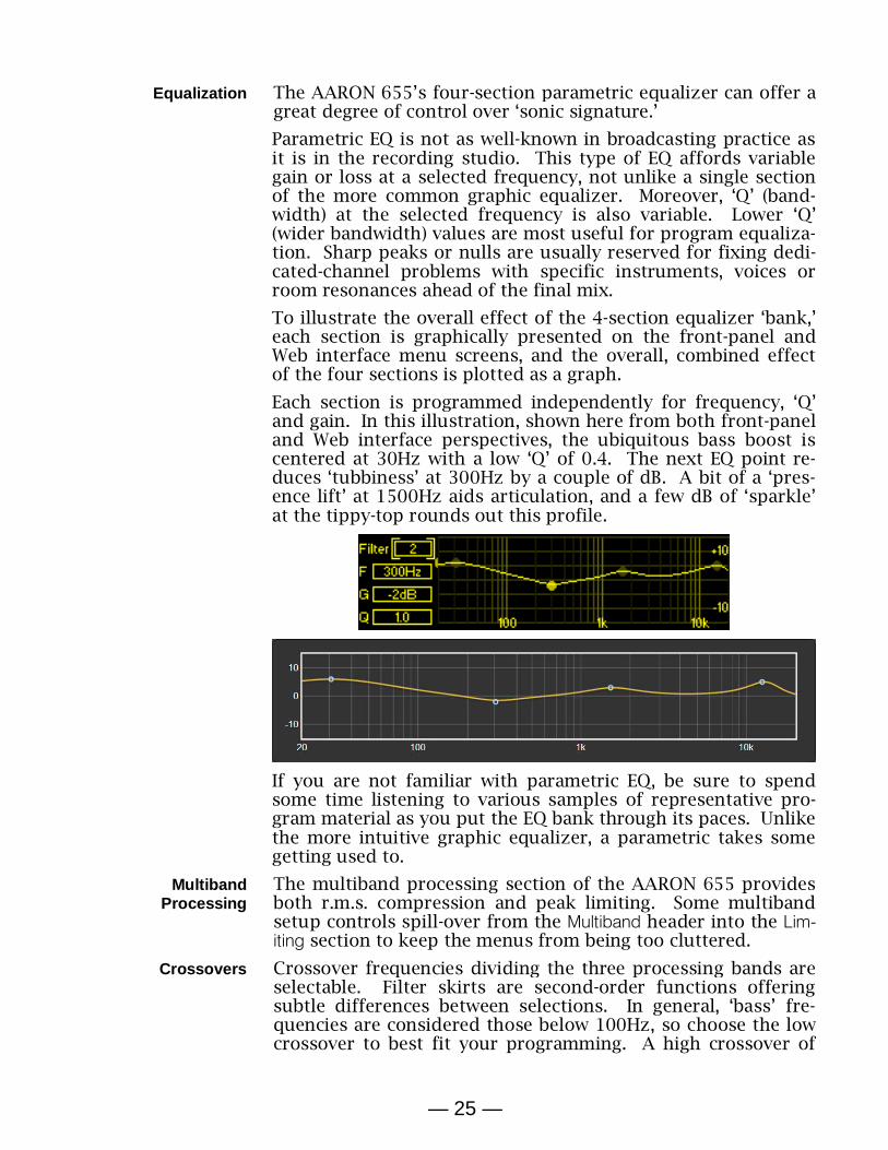
Equalization The AARON 655’s four-section parametric equalizer can offer a great degree of control over ‘sonic signature.’
Parametric EQ is not as well-known in broadcasting practice as it is in the recording studio. This type of EQ affords variable gain or loss at a selected frequency, not unlike a single section of the more common graphic equalizer. Moreover, ‘Q’ (band-width) at the selected frequency is also variable. Lower ‘Q’ (wider bandwidth) values are most useful for program equaliza-tion. Sharp peaks or nulls are usually reserved for fixing dedi-cated-channel problems with specific instruments, voices or room resonances ahead of the final mix.
To illustrate the overall effect of the 4-section equalizer ‘bank,’ each section is graphically presented on the front-panel and Web interface menu screens, and the overall, combined effect of the four sections is plotted as a graph.
Each section is programmed independently for frequency, ‘Q’ and gain. In this illustration, shown here from both front-panel and Web interface perspectives, the ubiquitous bass boost is centered at 30Hz with a low ‘Q’ of 0.4. The next EQ point re-duces ‘tubbiness’ at 300Hz by a couple of dB. A bit of a ‘pres-ence lift’ at 1500Hz aids articulation, and a few dB of ‘sparkle’ at the tippy-top rounds out this profile.
If you are not familiar with parametric EQ, be sure to spend some time listening to various samples of representative pro-gram material as you put the EQ bank through its paces. Unlike the more intuitive graphic equalizer, a parametric takes some getting used to.
Multiband Processing
The multiband processing section of the AARON 655 provides both r.m.s. compression and peak limiting. Some multiband setup controls spill-over from the Multiband header into the Lim-iting section to keep the menus from being too cluttered.
Crossovers Crossover frequencies dividing the three processing bands are selectable. Filter skirts are second-order functions offering subtle differences between selections. In general, ‘bass’ fre-quencies are considered those below 100Hz, so choose the low crossover to best fit your programming. A high crossover of

— 26 —
2kHz complements the US 75-microsecond pre-emphasis char-acteristic, although a 3kHz choice may give a less pronounced midrange. 3kHz matches the European 50µs curve.
‘Master’ and Band Drives
Adjust overall Drive to the triband section under the Limiter sub-menu. This also is where you’ll find a slider to set the ratio of r.m.s. to peak limiting in the three bands. r.m.s G/R (gain re-duction) is shown by the solid or yellow portion of the LO/MID/HI G/R meters, and peak limiting by the floating seg-ment or blue portion of the bar.
Drive and RMS/Peak will have greatest effect over how ‘busy’ the program sounds. Multiband processing fills voids in the pro-gram spectrum. r.m.s. control will give a smoother sound and peak-based control a greater spectral density.
Under Multiband/Band Drive, independent control over the input to each band gives a certain degree of static equalization, plus an ability to normalize compression and limiting among the three bands.
Band Uncoupling
With most program material, the mid band contains the highest energy and is thus considered the ‘master’ band in the multi-band section. Band Uncoupling allows you to slave the action of the low and hi bands to that of the mid band. When fully cou-pled (0% Uncoupling), mid-band G/R will also reduce gain in the slaved bands, giving more of a single-band processor action. The slaved bands will still be able to reduce gain above the midband G/R level, but will not release to a value lower than that of the mid band. As Uncoupling is advanced, you get more of a multiband effect.
Bass Punch This is a bass-enhancement feature that accentuates the initial impact of drums or the pluck of a bass guitar string. This is a dynamic function and will have no effect on sustained bass ma-terial. Bass Punch bypasses the multiband section, so its action will not be evident in the multiband metering.
Limiting In addition to the Triband Drive and RMS/Peak adjustments above, the Limiting submenu has a few more user controls.
WB Release WB Release establishes a dual-release function and will have the greatest effect over perceived loudness in the rebroadcast pro-gram.
The time-averaged value of final limiting establishes a release ‘platform.’ Program peaks quickly release to this platform, which itself then releases at a slower rate. WB Release sets the platform level with relation to peak gain reduction. The plat-form is the solid or yellow portion of WB metering, fast peak re-lease is seen as the hovering segment or blue section of the display. A default value of ‘0’ is a safe compromise between ‘smooth’ (–10) and ‘loud’ (+10). Your station programming and personal preference will dictate a proper setting for your pur-poses.

— 27 —
HF Limiting and Clipping
FM broadcasting is a transmission system that employs com-plementary pre-emphasis and de-emphasis, requiring an inde-pendent high-frequency limiter to avoid overmodulation. The AARON 655 uses both HF limiting and distortion-cancelling HF clipping to meet this requirement.
HF Limit-Clip covers the range between full limiting (–10) to most-ly-clipping (+10), with ‘0’ being the default compromise. Full HF limiting can sound somewhat dull. But even with distortion-reduction techniques, HF clipping can put an ‘edge’ on vocals and various other sounds rich in high frequencies. Be sure to listen to a representative sample of your programming before settling on an adjustment here.
Composite Clipping
A modest increase in ‘modulation efficiency’ may be gained through judicious clipping of the composite multiplex wave-form. This must of course be effected before adding the 19kHz stereo pilot and any subcarriers to the baseband signal.
MPX Clipping is adjustable between 0dB and 3dB. Clipping on the order of 1dB is nearly always safe from a sonic and spec-trum-clutter standpoint.
Processor Bypass
The Bypass mode simply removes the entire audio processing function from the program signal path. Composite Clipping is bypassed as well.
Test Oscillator Engaging the Test Oscillator disconnects program audio from the input of the audio processing section and allows you to feed this point with a tone. Default is Off, of course, and the oscil-lator tone may be fed to left L only or right R only channels independently or to both L+R program channels.
The Frequency and the Level of the tone are both adjustable from this menu. A Level setting of –10dB is equivalent to a con-sole ‘zero-VU’ level and will center the gain-riding AGC func-tion. Depending on the processor setup you may see little oth-er meter action with a tone, as subsequent stages respond pri-marily to program peaks.
DAYPARTING
NOTE: The daypart scheduler relies on at least an initial net-work connection to sync with Internet time, and with the prop-er time zone and other options selected. See Timekeeping Setup on Page 33.
As many as 20 ‘dayparts’ (changes in a station’s programming) may be scheduled by this built-in feature of the AARON 655. Audio processing presets may be called-up for scheduled devia-tions in the station’s format during the broadcast day. A sta-tion might depart from jazz music to a big-band segment, for example, or from music to regularly-scheduled talk program-ming or a satellite-delivered news feed.

— 28 —
From the Processor/Daypart menu, enter a processing Preset that you have selected for the scheduled program-ming segment. You may se-lect one or more Days of the week that the segment will be aired, and the Hour and Min (minute) it begins, AM or PM. In this example the station airs a religious roundtable discussion on Sunday at 11:00AM. A second daypart, to return to the sta-tion’s music format will have been set for noon.
Once a programmed daypart begins it will continue indefinitely. Thus it is important to set up your ‘normal’ processing as a daypart as well, and program the scheduler to switch back when the alternative programming ends.
THE FM STEREO GENERATOR
Setups of the stereo-gen and RDS encoder are performed under the Setup/Outputs/Stereo Generator menu.
NOTE: The AARON 650 features a multiplex ‘servo’ utility that maintains a constant composite/MPX output despite ste-reo/mono switching or pilot and RDS injection level changes.
Pre-Emphasis The Pre-Emphasis submenu allows selection of either the 50µs European or the 75µs North American transmission characteris-tic.
Transmission Mode
Under Stereo/Mono, normal operation is, of course, Stereo, alt-hough you may force monaural operation by selecting one of three options.
Mono L+R sums the left and right channels for retransmis-sion without the stereo subcarrier and 19kHz pilot. This is the default mono mode, of use with talk programming or to extend the noise-free coverage area of the station at the expense of stereophony. But because dropping one channel would result in a drop in total modulation to 50%, two other choices are available.
Mono L and Mono R allow monaural transmission at full car-rier deviation from either the left-only or the right-only chan-nel. This could be of value if, for example, one STL channel goes dead, or a stereo STL has to be used in an emergency situ-ation to feed two transmitters with different programming.
Pilot Injection is an adjustment under this same menu subhead. Normal 19kHz stereo pilot injection is 9%, although the actual injection may be set between 6% and 12%.
Multiplex Output The Multiplex Out submenu is for setting the composite/MPX output of the AARON 655 to a precise level for 100% modula-tion of the FM carrier. This control has a range of 1.00Vpp to 6.00Vpp, and the MPX adjustment slider gives logarithmic (dB)

— 29 —
control between these levels with an exact volts peak-to-peak indication below. The value shown is the open-circuit voltage output from a 75-ohm source impedance.
THE RDS ENCODER
The RDS Encoder menu is under Stereo Generator and facilitates setup of the ‘internal’ RDS message, or of reformatted metadata from a selected input that allows this option.
Subcarrier Injection
The Injection slider sets the percentage injection of the RDS sub-carrier with respect to total carrier modulation. A typical value is 5%.
The RDS subcarrier is enabled, or not, when the Input Source is selected. From the Main Menu, under Input Sources, set RDS: None to disable the RDS subcarrier.
Static RDS Data Entry
RDS Data is a data-entry field for the ‘Internal’ fixed RDS mes-saging.
A PI hex value should always be entered. This is essentially the station’s ‘digital address,’ used by some consumer radios to au-to-tune to a station’s translator(s).
NOTE: Your rebroadcast translator may require a PI code that is different from the main channel. That PI code should be en-tered into the PI box, even if RDS is reformatted from an input source.
If you are receiving and rebroadcasting the station’s FM signal, with an input source selection of RDS: FM RDS, the PI code entered here will be broadcast instead of the PI code of the main signal if the Use new PI Code (FM) box is checked (see Options, below).
With an HD Radio channel, line input or streaming input as the signal source, the PI code of the main FM signal should be entered if RDS is being transmitted by your re-broadcast translator.
Similarly, PTY identifies the station’s format. Radios use this to search-out and tune-to a listener’s program preferences.
PS, or the Program Service Name can be either a static, 8-character station ID: LIVE 105, or a slogan or promo up to 128 characters (including spaces). Messages exceeding 8 characters will scroll across the faceplate of any RDS receiver: BOSS-FM, ON THE AIR EVERYWHERE.
The same applies to RT, or Radio Text, which is a 64-character scrolling message that can be read on some radios. This usual-ly lists the station’s Website and phone number, or promotes an upcoming event.

— 30 —
Housekeeping ‘flags’ include M/S, identifying the program as Music or Speech, TP to identify a station that broadcasts traffic information, and DI to denote Stereo or Mono programming.
Options RDS Options includes Use new PI Code (FM) to separate a trans-lator’s ID from that of the main transmitter. Send time group broadcasts the date and local time, using the Internet as a time standard and updating the clock on consumer radios.
If you elect to Send time group, be sure to set the AARON 655 real-time clock parameters. Offset from UTC, Stand-ard/Daylight settings and at least initial sync with the Internet time server are covered under Setup/Network/Time/Time Zone & DST (see Page 33).
Scrolling Speed PS Scroll Speed sets the scrolling rate of an internal PS message consisting of more than the eight static characters that would be displayed on a consumer radio. A midway setting of 5 is usually safe, but scrolling the PS message too fast can display gibberish on some radios.
Alternative Frequencies
In the AF List, checkmark the frequency of any and all transla-tors that rebroadcast the same programming as you main sig-nal. Be sure to enter the frequency of your main signal as well. Radios use this information for ensuring the best reception as a mobile listener encounters varying signal conditions.
HD to RDS HD to RDS reformats incom-ing HD Radio PAD data to outgoing RDS. In the HD DPS example here, we have interspersed text entered into the boxes on the left with off-air HD Radio PAD data from categories in the boxes on the right. In this example, the RDS PS field will scroll: We are KRTH-FM Now Playing U2 …The
Greatest Hits on Earth! The off-air PAD Name follows the first text block, the PAD Artist follows the second one. Finally, an ellipsis (the three periods) is followed by the off-air PAD Slo-gan. HD Radio Text is programmed in exactly the same manner.
Streaming to RDS
Stream to RDS conversion is identical to the above. (All of this is most easily set-up using the AARON 655 Web interface.)
Telnet Telnet allows data incoming from the Web to update RDS PS and Radio Text fields ‘on the fly.’ Conceivably the station automa-tion playout system could send dynamic data to the AARON 655 for scrolling artist and title. This is an unusual task for a rebroadcast receiver. Nevertheless, note the info below.
The incoming data syntax for scrolling PS requires a preamble of DPS=, followed by the artist and title and concluded with an Enter (‘carriage return’) ASCII symbol. Here’s an example:
DPS=Staying Alive by the Bee Gees
The same goes for Radio Text, except the preamble is TEXT=. For example:

— 31 —
TEXT=BOSS-FM Plays your requests: 1-800-555-1212
To put the same information into both fields, the preamble is DPSTEXT=
You must check the Enable box under Telnet, and either verify the default Port: number or enter a proper one.
PROGRAM LINE OUTPUTS
Setup of the analog and digital program line outputs was de-tailed beginning on Page 13.
NETWORK SETUP
DHCP IP Assignment
With the AARON 655 LAN jack connected to your net-work, navigate from the Main Menu to Setup/Network/ IP Settings. Here you may se-lect: DHCP to have your router automatically assign an IP ad-dress to the receiver. Once DHCP connection is established, the fields on the right-hand side of the screen will populate auto-matically.
Manual IP Setup
For any of several reasons you may need to set the IP address of the AARON 655 manually. Select the Static IP radio button and use the knob to bracket the various network setup options. Use Backspace to erase an entry or to make corrections, and when you’re finished be sure to Save each new entry.
It is not within the scope of this discussion to detail the com-plete static-IP setup procedure, but a competent IT professional should be familiar with the intricacies of this operation.
Assigning a Hostname
Setup/Network/Hostname lets you assign a specific name to the AARON 655 to identify it on your network. You may change the default name AARON655 to personalize the equipment name, or to differentiate one AARON655 from another on the same network.
Enter a hostname in all-capital letters. The Hostname assign-ment cannot include spaces. Be sure to Save the name once you’ve entered it.
It is not necessary to use all-caps when addressing the mon-itor, however. Under Windows operating systems you may ac-cess the AARON 655 through a Web browser on the same net-work simply by typing its name and a forward-slash into the browser address bar as shown here.

— 32 —
Non-Windows browsers may require you to enter the complete IP address of the unit, which you may find by front-panel navi-gating to Setup/Network/IP Settings.
Remote Access
On a common local network (LAN), access the receiver’s Web interface by entering its IP address or, under Windows, its Host Name into your browser’s address bar as shown above. To ad-dress the AARON 655 from the Internet the unit must have a static IP address. If your router makes DHCP assignments for other equipment on the network, simply assign the receiver a static IP that is outside the router’s DHCP range. This is an easy matter with the aid of the router’s Help utility.
You also need to open a specific port for the AARON 655 on the net-work router. Within the router’s Port Forwarding utility you will be able to enter your static IP ad-dress for the unit (Internal IP), followed by a colon and a port number. The port number may be any number in the router’s range. If your Internet Service Provider (ISP) assigns you a stat-ic IP address, then it is a simple matter to address the receiver from anywhere. Just type the IP address and port number into your browser as shown in this example .
But if your ISP provides you a dynamic IP, which is most often the case, this mandates ‘Dynamic DNS’ operation, using the services of an IP-forwarding provider.
Dynamic DNS IP-forwarding providers available on the Internet will allow you to address equipment behind a dynamic IP address. Their ser-vice will allow the AARON 655 to keep the provider apprised of its reassigned IP address each time your ISP updates it. The service intercepts data attempting to connect with your AARON 655 and converts the IP address to the updated one.
There are three popular DNS service providers on the Internet. Their basic service (all you really need) may be free of charge, but advanced features may command a nominal annual fee. All services require registration on the appropriate Website.
Under the Setup/Network/Dynamic DNS menu, Disabled is the de-fault Mode: selection. Scroll through the options and jot down the three popular providers shown. Do a Web search to learn more about their services and to register with your choice.
When you register, the pro-vider will issue you a Host-name, Username and Pass-word. Use the front-panel knob to enter these into the Host:, User: and Pass: fields. When finished, the screen should look something like the example shown.

— 33 —
Timekeeping Setup
Under Setup/Network/Time/Time Zone & DST, use the Time Zone slider to select your local zone with respect to UTC.
An Internet connection will sync the internal real-time clock with the online time server. Today’s date and the local time should appear at the bottom of the menu. Maintaining an In-ternet connection will assure that time will remain correct.
Auto DST is the default set-ting for Daylight Saving time. Force DST by checking the
DST box. Uncheck both boxes to ignore DST com-pletely.
Network Status Setup/Network/Status brings up a screen that gives full particu-lars of the network connection. This screen is useful for trou-bleshooting and for verifying connection parameters.
SNMP OPERATION
SNMP Overview SNMP (Simple Network Management Protocol) allows other TCP/UDP/IP equipment on the same Local Area Network (LAN) to communicate directly with the AARON 655, and for the unit itself to initiate an alarm on the network.
The AARON 655 will interface directly with a network control-ler, technically known as the SNMP ‘Manager.’ The AARON 655 incorporates an embedded ASCII text file called a Management Information Base, or MIB. In setting up for SNMP operation, the MIB file will have to be downloaded from the AARON 655 using the Web interface (see Page 41), and uploaded to the SNMP Manager.
SNMP Mode Go to Setup/Network/SNMP/ Mode & Communities. The default set-ting for Mode: is Disabled, which inhibits communication be-tween the AARON 655 and the SNMP Manager.
Changing Mode: to Read Only allows the AARON 655 to be inter-rogated by the SNMP Manager, so that stream metadata, alarms, etc. can be integrated with other equipment on the network.
Setting the Mode: to Read & Write allows the SNMP Manager to send commands to the AARON 655.
SNMP Security SNMP ‘Communities’ serve as passwords for this function. Go into the Mode & Communities Read: and Write: boxes to enter text that is specified for the read/write strings on the SNMP Manag-er monitoring device. As with similar text-entry screens, exe-cute a Save after entering.

— 34 —
SNMP Ports The default SNMP Ports, General Port: 161 and Trap Port: 162, are customary for a majority of SNMP operations. These may be changed as required.
SNMP Traps When the AARON 655 initiates an alarm, rather than being que-ried or polled for one, the alarm is known as a ‘trap.’ Navigate to Setup/Network/SNMP/Trap Destinations. Here three local net-work IP addresses may be entered, each corresponding to other devices on the LAN that want to be apprised of alarms.
NOTE: This is an abbreviated discussion of SNMP operation. SNMP is a complex utility, managed exclusively by whatever SNMP ‘Manager’ (monitoring equipment) is employed. Refer to all instructions for the SNMP Manager in setting-up the AARON 655. From the active AARON 655 browser screen, download the MIB file for further clarification (see Page 41).
ALARMS AND NOTIFICATIONS
Basic setup of AARON 655 alarms was described earlier as part of the Program Failover feature. Refer back to margin headings with the word Alarm beginning on Page 19 for instructions on setting alarm parameters. The balance of this discussion re-volves around how the various alarms are directed and logged.
Alarm ‘Tallies’ The rear-panel GPOs (General Purpose Outputs) give access to closures (or opens) to ground for any of the various alarms. Open the submenu at Setup/Outputs/General Purpose Outputs.
There are six GPOs, any of which may be assigned to any of the alarm functions. In the example shown, Out-put: 1 will be taken to ground when the Radio Audio Loss is activated per the parameters set on Page 20. The other five, Output: 2 to Output: 5, may be assigned to other alarms (Type: Analog Audio Loss / Digital Audio Loss / Stream Audio Loss / Low Signal / RDS Error / Pilot Loss / HD Loss), and the alarm polarity set to Active Ground or Active Open.
Email & Text Notifications
NOTE: The time-stamp feature for email notifications and the Alarm Log depends on at least an initial network connection to sync with Internet time, and the proper time zone and other options selected. See Timekeeping Setup on Page 33.
Once connected to the Internet, the AARON 655 can send email or SMS/text notifications to one or more recipients. Which alarms go to whom is a programmable function as well.
SMTP Setup The AARON 655 must first be properly programmed to send mail under the Setup/Email Preferences menu. You need to set up an actual email account, the elements of which are just like any other email account setup. This information depends on the provider you choose. When you apply for the account, much of

— 35 —
this information will be assigned to you.
NOTE: As of initial product release, some email servers may not support SMTP mail dispatch from the AARON 655. This situation is in a state of flux at present. The TLS1.2 standard is supported, STARTTLS is not. A simple and free Gmail account would be a good choice if your in-house mail system fails to send mail due to this issue.
Under SMTP Server, enter the provided outgoing mail SMTP Serv-er info (e.g. smtp.gmail.com), the required Port: number and whether or not to Use SSL.
Under Sender, From: is the ‘friendly’ name that will identify the AARON 655 to the email or SMS/text recipient. User: is the full email address of the unit, and Pass: is the password you’ve as-signed to the account.
Next enter email recipients separately under the Set-up/Email Preferences/Recipients menu. You may enter up to ten separate email address-es.
Sequentially, choose Select: 1. through 10., enter the Ad-dress: field, type-in the email address, then select Save.
Then from the Main Menu open Alarms & Notifications/ Email Notifications. Here you can pull-up any recipient in the list you’ve created and select which alarm or alarms sends that person an email alert. From that same list you may also send the same person a com-plete log of all alarms. Scroll down and check your preference of a Daily, Weekly or Monthly Alarm Log.
Finally, use the Send Test Email utility to ensure that the AARON 655 is capable of sending mail properly to all recipients.
Alarm Log Settings
Under Setup/Alarm Log Settings you’ll find a Status: notation of how full the log is at the moment. Although the log is capable of containing a couple of thousand events, it might be im-portant to know when you have accumulated a certain number of entries, as this could be an indication of some recurring problem. Enter the Email When: box and set a number. A set-ting of 10% equates to about 200 log entries.
The Alarm Log will continue to accumulate entries, but you may manually clear it at any time. Under Alarm Log Settings, go to Clear Log at the

— 36 —
bottom of the screen. Bracket and select the box, and when prompted push the knob again to delete all alarm history. The AARON 655 Web interface provides means of downloading the alarm log for study and analysis if desired.
MISCELLANEOUS SETTINGS
Passwords All AARON 655 settings may be protected by a password, which must then be entered before any subsequent changes can be made. Either the same or separate passwords may be assigned to lock out the front-panel and Web interface access.
From the Main Menu, navigate to Admin/Security. Enter either or both boxes to manually enter a password for Front Panel: or Webpages: with the jog-wheel knob. Highlight Save and push the knob to set the password in memory.
Passwords will be displayed on the setup screen, but only au-thorized users will be able to open that screen to see them. Ac-tivate and test password access by holding down the Back but-ton for a few seconds.
Once the password is saved, the Now Playing screen will be the only menu item available. Press the Back button to sign-in.
The AARON 655 will lock any time the screen times-out (goes dim or dark) after the unit is untouched for the programmed timeout period. It may be locked immediately by holding down the Back button.
Once password protection is in place, you will be prompted to enter the password before any menu can be accessed and any adjustments made. After entering the password, highlight: Done and push the knob. This will be necessary each time the unit is awakened from a dark screen. Similarly, the Webpages: password must be entered on the controlling computer when-ever connection is made via the Web.
When working on a protected unit over an extended period, you can obviate the frustration of having to keep re-entering a password by resetting the Admin/Display/Timeout setting to 60 min. From the Admin/Security screen you could also Backspace to delete the password, but of course jot it down first so you can re-enter it when finished.
Lost Password (Hard Reset)
To recover control of the AARON 655 if the password is lost, you must do a “hard reset.” This is accomplished by holding down the Back button as you power-cycle the unit (disconnect and then reconnect AC-mains power).
NOTE: A hard reset deletes not only the password, but will also return the AARON 655 to all-factory-default values. All User settings will be lost! This illustrates the importance of keeping a Hardware Profile current (see Page 41).

— 37 —
Display Settings
The Admin/Display menu offers a Brightness choice for the OLED menu screen. You may change this from a 60% default value to a higher or lower setting. We don’t recommend a much higher setting because this may shorten the life of the OLED graphic display module, and it doesn’t really look much brighter any-way. A lower setting actually appears a bit sharper and kinder on the eyes in subdued lighting.
Timeout programs the interval between last use of the jog-wheel knob and the screen’s going into its ‘screen-saver’ dark or dim mode. This may be set in 5-minute increments between 5 min and 60 min. You may put the unit into the screen-saver mode manually by holding-down the Back button.
Check Dim to keep the screen from blacking-out entirely at the end of the Timeout interval.
About The About screen shows the current Firmware Rev:, Serial #: of your unit, Ethernet: port status, the and Uptime:, or how long the AARON 655 has been running since power was last applied.
Headphone Volume
Headphones rarely needs to be brought up manually as this menu automatically pops up whenever a pair of headphones is plugged into the front panel jack.
Headphones/Volume adjusts listening level, and a Source: selec-tion allows you to preview any of the individual program input choices without putting them on air. The default Source: selec-tion is Proc. Out, the output of the audio processing section.

— 38 —
Section IV
THE WEB INTERFACE
GENERAL
The ‘responsive’ design of the AARON 655 Web interface pro-vides an optimal viewing experience across a wide range of de-vices. A minimum of resizing, panning or scrolling is required with any device, from desktop computer monitors to tablets to mobile phones.
The previous section of the manual detailed setup of the AARON 655 using front-panel ‘knob and button’ data entry. Suffice it to say that setup is easier and faster with a conven-tional keyboard, once the unit’s Webpages can be brought up in a computer browser.
Because the functionality of the Web interface is identical to what can be accomplished from the front panel, it would be confusing and redundant to detail each Web screen here. All functions of the AARON 655 have already been covered from a front-panel perspective. If you have a question that is not an-swered in this section, consult the Table of Contents for a dis-cussion of your query in the previous Section III.
The Web interface menu is arranged in much the same order as the front-panel menu tree, but you will find some functions or-ganized a bit differently between various presentations on a desktop PC, tablet or mobile device. All menus are available remotely, however, so if one seems to be missing, just look around… it’s there.
CONNECTING TO THE AARON 655
Once you have a computer, tablet or mobile device connected to the same network as the AARON 655, from a Windows-environment browser type in the Host Name followed by a / (forward slash). Otherwise enter the full IP address of the re-ceiver, found under Setup/Network/IP Settings. This will take you to the AARON 655 main Now Playing Webpage shown on the next page.

— 39 —
THE WEB INTERFACE PAGES
Each of the individual AARON 655 Webpages will feature the main menu down the left side of the screen. It follows the front-panel menu tree with only occasional meandering. For computer or tablet browser screens with good resolution we are able to consolidate menu functions, so Web interface Menu choices may be greater (or fewer!) for different Web-enabled devices. Everything will be there somewhere, however, so scan the various screens to learn the correlation between front-panel menu choices and what is displayed on your Web-enabled de-vice.
The main Now Playing screen pictured features level metering at the top, along with the remote listening function. These two utilities appear at the top of every Web screen.
Now Playing also shows the status of basic alarms, and shows info about the program source and its metadata. The layout of this page will change somewhat, depending on what program source is currently selected. This is also where you assign pri-orities to Input Sources and their triggers for program failover.
Remote Listening
Click the loudspeaker icon at the top of the screen to listen to the audio program. The 128 box to the left of the icon sets the audio monitor streaming rate. 128kbps is default, but this can be lowered to 64kbps or even 32kbps if your network connec-tion is very slow. The box a bit more to the left, marked Pro-cessor, is for selecting the source you are actually listening to. The output of the processing section is the default, but you can
— 40 —
listen to any of the incoming ‘raw’ program sources without changing or interrupting the actual rebroadcast program source.
‘VU’ Meter As explained earlier, the on-screen meter emulates a ‘VU’ me-ter, but does not have proper ‘VU’ ballistics. It is peak-responding with a 10dB calibration offset to compensate for program waveform crest factor. This meter always bridges the gain-trimmed program feed at the input to the audio pro-cessing section.
THE MENU LIST
Tuning the Radio
Under the Radio menu you’ll find all options having to do with off-air reception, including the regional RDS/RBDS: selection and the BandScanner utility. The radio may be tuned either with the Frequency (MHz): slider, or by clicking the slider knob and then using the keyboard < and > cursor buttons to incre-ment tuning, or by entering a frequency directly into the box left of the slider. This screen makes it easy to set up radio alarm parameters too, and gives a comprehensive display of FM and HD Radio metadata.
Inputs All AARON 655 inputs are concentrated under the one Inputs menu. Analog, Digital, Stream, all their alarms setups, and even General Purpose Inputs appear and may be assigned or adjusted here.
Outputs The Outputs menu contains all setup parameters for the Stereo Generator (except for RDS setup, which has its own menu), Ana-log and Digital outputs, and the General Purpose Outputs with their function and polarity selections.
Audio Processing
Details regarding the AARON 655’s audio processing section begin on Page 23. The Web interface Processor settings, con-trols and menu organization are nearly identical.
RDS Encoder RDS Encoder is a menu item unto itself in the Web interface. All RDS-related items (see Page 29) will be found on this one Webpage.
Alarms The Alarms Webpage only indicates Alarm Status and gives ac-cess to the Alarm Log. Alarm setup is still found on the Webpage associated with the individual function. For example, setup of the Digital Audio Loss alarm is done under In-puts/DIGITAL/Digital Audio Loss.
Network Settings The Network Webpage combines the front-panel IP Settings and Hostname menu items. Dynamic DNS and the Time settings are as straightforward as detailed in Section III. SNMP places all settings related to this feature on this one Webpage, but also addresses the SNMP/MIB File, discussed next.
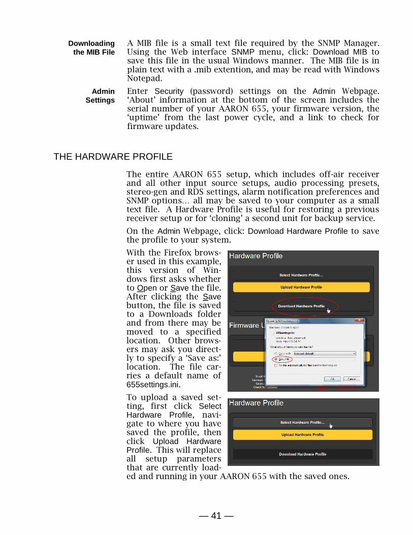
— 41 —
Downloading the MIB File
A MIB file is a small text file required by the SNMP Manager. Using the Web interface SNMP menu, click: Download MIB to save this file in the usual Windows manner. The MIB file is in plain text with a .mib extention, and may be read with Windows Notepad.
Admin Settings
Enter Security (password) settings on the Admin Webpage. ‘About’ information at the bottom of the screen includes the serial number of your AARON 655, your firmware version, the ‘uptime’ from the last power cycle, and a link to check for firmware updates.
THE HARDWARE PROFILE
The entire AARON 655 setup, which includes off-air receiver and all other input source setups, audio processing presets, stereo-gen and RDS settings, alarm notification preferences and SNMP options… all may be saved to your computer as a small text file. A Hardware Profile is useful for restoring a previous receiver setup or for ‘cloning’ a second unit for backup service.
On the Admin Webpage, click: Download Hardware Profile to save the profile to your system.
With the Firefox brows-er used in this example, this version of Win-dows first asks whether to Open or Save the file. After clicking the Save button, the file is saved to a Downloads folder and from there may be moved to a specified location. Other brows-ers may ask you direct-ly to specify a ‘Save as:’ location. The file car-ries a default name of 655settings.ini. To upload a saved set-ting, first click Select Hardware Profile, navi-gate to where you have saved the profile, then click Upload Hardware Profile. This will replace all setup parameters that are currently load-ed and running in your AARON 655 with the saved ones.

— 42 —
NOTE: Uploading a Hardware Profile reboots the AARON 655. After the reboot, an information screen pops up to remind you of important operating procedures and to guide you through any problems that might have arisen after the reboot, or give you the option of restoring factory default settings.
UPDATING FIRMWARE
AARON 655 firmware and Web interface pages are easily up-loaded to the unit when updates are issued by Inovonics.
NOTE: It would be a very good idea to update your Hardware Profile as a firmware update may affect some user settings.
Updates are issued as small .bin files which may be downloaded to your computer Desktop or placed in any convenient folder. From the Firmware Update utility at the bottom of the Admin screen, click Select Firmware File… and then navigate to the downloaded file and double-click it. This will transfer the file, name to the updater as shown here.
Click Update Firmware and follow prompts to complete the pro-cess. Updating takes a couple of minutes and will return you to the Web interface pages once the operation is complete.
any problems that might have arisen after the reboot, or give you the option of restoring factory default settings.

INOVONICS WARRANTY
I TERMS OF SALE: Inovonics products are sold with an understand-ing of “full satisfaction”; that is, full credit or refund will be issued for products sold as new if returned to the point of purchase within 30 days following their receipt, provided that they are returned complete and in an “as received” condition.
II CONDITIONS OF WARRANTY: The following terms apply unless amended in writing by Inovonics, Inc. A. Register the Warranty online at www.inovonicsbroadcast.com
within 10 days of delivery. B. This Warranty applies only to products sold “as new.” It is ex-
tended only to the original end-user and may not be transferred or assigned without prior written approval by Inovonics.
C. This Warranty does not apply to damage caused by misuse, abuse, accident or neglect. This Warranty is voided by unau-thorized attempts at repair or modification, or if the serial identifi-cation label has been removed or altered.
III TERMS OF WARRANTY: Inovonics, Inc. products are warranted to be free from defects in materials and workmanship. A. Any discrepancies noted within THREE YEARS of the date of
delivery will be repaired free of charge, or will be replaced with a new or remanufactured product at Inovonics’ option.
B. Parts and labor for factory repair required after the three-year Warranty period will be billed at prevailing prices and rates.
IV RETURNING GOODS FOR FACTORY REPAIR: A. Equipment will not be accepted for Warranty or other repair with-
out a Return Authorization (RA) number issued by Inovonics pri-or to its return. An RA number may be obtained by calling the factory. The number should be prominently marked on the out-side of the shipping carton.
B. Equipment must be shipped prepaid to Inovonics. Shipping charges will be reimbursed for valid Warranty claims. Damage sustained as a result of improper packing for return to the factory is not covered under terms of the Warranty and may occasion additional charges.
Revised May, 2017 INOVONICS, INC. +(831) 458-0552