Embed Size (px)
Citation preview
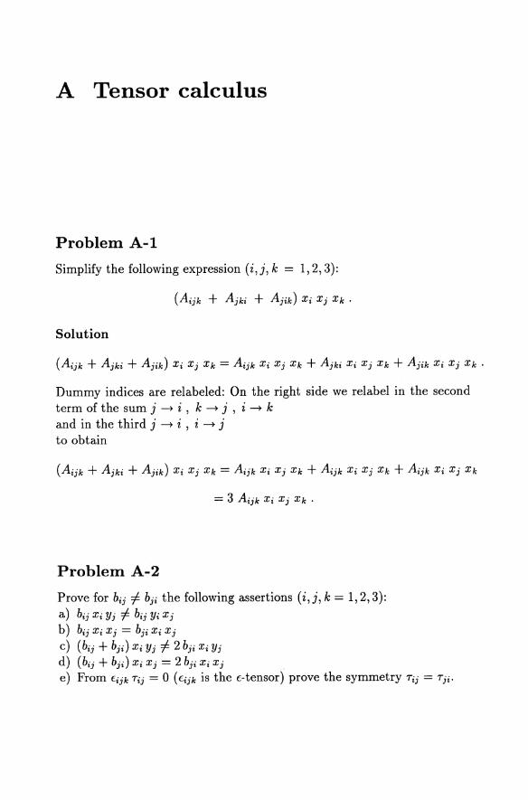
A Tensor calculus
Problem A-l
Simplify the following expression (i,j, k = 1,2,3):
Solution
( k-k + kk- + k-k) x- x- Xk - k-k x- x- Xk + kk- x- x- Xk + A--k x- x- Xk 'J J ' J' 'J - '3 , J J' , 3 3" J .
Dummy indices are relabeled: On the right side we relabel in the second term of the sum j --t i , k --t j , i --t k and in the third j --t i , i --t j to obtain
Problem A-2
Prove for bij =f. bji the following assertions (i,j, k = 1,2,3): a) bij Xi Yj =f. bij Yi Xj
b) b--x-x--b--x-x-'3 , 3 - J' , J
c) (bij + bji ) Xi Yj =f. 2 bji Xi Yj
d) (bij + bji ) Xi Xj = 2 bji Xi Xj
e) From fijk Tij = 0 (fijk is the f- tensor) prove the symmetry Tij = Tji.
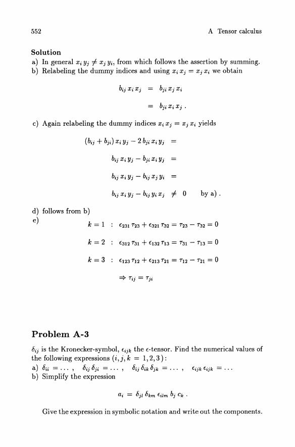
552 A Tensor calculus
Solution a) In general Xi Yj =1= Xj Yi, from which follows the assertion by summing. b) Relabeling the dummy indices and using Xi X j = X j Xi we obtain
c) Again relabeling the dummy indices Xi X j = X j Xi yields
(b·· + b··) X· y' - 2 b·· X· y' IJ J' 1 J JI 1 J
by a) .
d) follows from b)
e) k = 1
k=2 t312 731 + t132 713 = 731 - 713 = 0
k=3
Problem A-3
bij is the Kronecker-symbol, tijk the t-tensor. Find the numerical values of the following expressions (i, j, k = 1, 2, 3 ) : a) bii = ... , bij bji = . . . bij bik bjk ... , b) Simplify the expression
Give the expression in symbolic notation and write out the components.
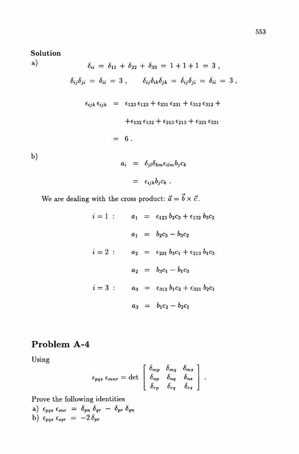
Solution a) 8ii = 811 + 822 + 833 = 1 + 1 + 1 = 3 ,
b)
6.
a· •
We are dealing with the cross product: a = b x c.
i = 1 : al E123 b2C3 + E132 b3 C2
al b2C3 - b3C2
i=2 a2 E231 b3 Cl + E213 b1 C3
a2 = b3Cl - b 1C3
i = 3 a3 E312 b 1 C2 + E321 b2Cl
a3 b1C2 - b 2Cl
Problem A-4
Using
Prove the following identities a) Epqs Esnr = 8pn 8qr - 8pr 8qn
b) Epqs Esqr = -28pr
553
554
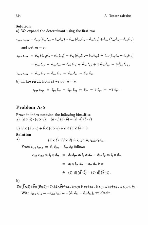
Solution a) We expand the determinant using the first row
and put m = s:
b) In the result from a) we put n = q:
Problem A-5
Prove in index notation the following identities: a) (a x b) . (e x d) = (a· C) (J. b) - (a . d) (b . C)
b) a x (b x C) + b x (e x a) + e x (a x b) = 0
Solution a)
b)
A Tensor calculus
ax (bx C)+bx (ex a)+ex (ax b)~flkn al fijk bi Cj+flkn bl fijk Ci aj+flkn Cl fijk ai bj .
With flkn fijk = -fink fkij = -( 8li 8nj - 8lj 8ni ), we obtain
Problem A-6
Show that Wik = Eikm Xm is an antisymmetric tensor of second order.
Solution
555
For Wik to be a second order tensor the equation w~s = air aks Wik must be satisfied where aij are the elements of the rotation matrix. Since Xm is a first order tensor and Eikm a third order tensor we have
hence Wik obeys the transformation rule for second order tensors. If Wik is anti symmetric then Wik = -Wki. Since Wik = Eikm X m , Wki = Ekim Xm and Ekim = -Eikm we get
i. e. Wik is antisymmetric.
Problem A-7
Show that the i-th component of
v X (V X it) equals 8Xi8Xj
556 A Tensor calculus
Solution The i-th component of \7 X (\7 X it) is
With Eijk Eklm = bilbjm - bim bjl from Problem A-4 a) we now find
Problem A-8
a) For the relation A = Aij Xi Xj , where Aij is constant, show
(1)
b) Prove that the gradient of the scalar function A = Aij Xi X j is a tensor of first order (Aij is a second order tensor).
Solution a)
By bik = ox;joxk therefore
On the right hand we relabel the summation index of the second term:
We now use k for the free index i and take Xj outside the bracket
557
b) We wish to show that the gradient transforms as a first order tensor
(~:J' = apl :~ .
Using
I Xm atm Xt ,
A:nl = arm asl Ars ,
A;m apl a qm Apq
we transform the right side of (1) into the new coordinate system:
1. e.
Problem A-9
Show, using cartesian coordinates that the identity
-+ -+ 1-+ n x (n x i) = - 2" \7 (n x i) 2
holds (see F. M. (4.~7)). iTo prove this it is not necessary to eliminate the E-tensor. But note: n f= n(i).)
Solution
The k-th component of (n x i) is Eijk ni Xj , and so the r-th component of f and 11:
558 A Tensor calculus
Since 0 =1= O(x)
1 a IIr = --E;J'k fmlk ftnm -(x' Xl) 2 . . aXr J
Problem A-lO
For the scalar field ~(r), with r = Jx; Xi show that a2~ ~'( X;Xj) X;Xj " '() d~ a) a a = - bij - -2- +-2- ~ ,where ~ r = -d ,and further Xi Xj r r r r
that
a2~ b) is a tensor of second order whose contraction is given by
aXjaXj
a2~ c)
aXiaXi
Solution a)
r
a~ ar d~ ar
aX; ar ax; dr ax; ,
where in the last term the partial derivative has been replaced by a total derivative since ~ = ~(r) only. Using
ar a 1 1/2 Xi ax; = ax/JXj Xj) = '2 (Xj Xjt 2 Xi = --:;:
we have a~ _ d~x; _ ~,Xi ax; - Tr--:;: - --:;:.
Differentiation with respect to Xj yields
a2~ _ ~ (~' Xi) aXiaXj - aXj r
if..11 Xi Xj if..,8ij if..' Xi Xj 'l" -+'l"--'l"-
r2 r r3 '
559
(P(P b) We wish to show that 8 8 transforms like a second order tensor
Xk XI
82(P 82(P = aki alj •
8xi8xj 8xk 8xI
With the orthogonal transformation Xk = aki xi we find
8xi
8x~8x'· , J
c) Laplace operator on (P(r):
(P' (c Xi Xi) if..11 Xi Xi Qii - -2- + 'l" -2-
r r r
(P' (3 - 1) + (p" r
~ (2 (p' + r (Pll) r
1 d ( ') = --(P+r(P , r dr
560 A Tensor calculus
Problem A-11
For a scalar field cI>(X', t) and the vector field a(X', t) = Ul el + U2 e2 + U3 e3 in cartesian coordinates a) show that
curl( cI> a) = cI> curl a + grad cI> x a . (1)
b) Write equation (1) using the Nabla operator V. c) Prove equation (1) in index notation.
Solution a)
curl
cI> curl '11 + grad cI> xu.
b) Equation (1) using the Nabla operator
reads V' x (cI> '11) = cI> V' x '11 + V' cI> xu.
c) The k-th component of (1) is
8( cI> Uj) 8uj 8cI> f.ijk 8 = cI> f.ijk -8 + f.ijk -8 Uj
Xi Xi Xi
For k = 1, 2, 3 we get:
k = 1:
k = 2:
k = 3:
561
B Examination problems
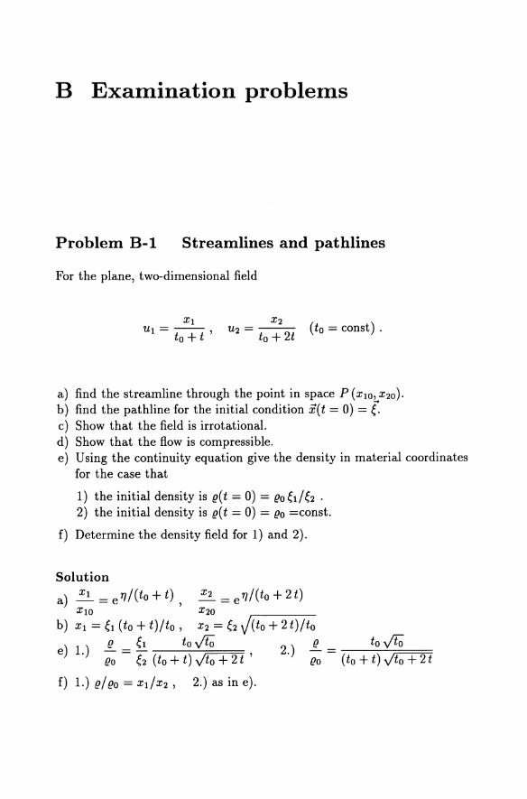
Problem B-1 Streamlines and pathlines
For the plane, two-dimensional field
Xl U --
I - to + t ' (to = const) .
a) find the streamline through the point in space P (XlO' X20)'
b) find the pathline for the initial condition x( t = 0) = (. c) Show that the field is irrotational. d) Show that the flow is compressible. e) Using the continuity equation give the density in material coordinates
for the case that
1) the initial density is e(t = 0) = eo6/6 . 2) the initial density is e(t = 0) = eo =const.
f) Determine the density field for 1) and 2).
Solution
a) ~ = e TJ / (to + t), ~ = e TJ / (to + 2 t) XIO X20
b) Xl = 6 (to + t)/to , X2 = 6 J(to + 2t)/to
e) 1.) ~ = 6 to 00 , 2.) ~ eo 6 (to + t) Jto + 2 t eo (to + t) Jto + 2 t
f) 1.) e/ eo = XdX2' 2.) as in e).
563
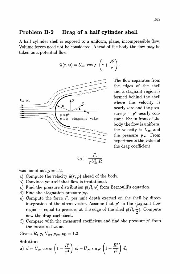
Problem B-2 Drag of a half cylinder shell
A half cylinder shell is exposed to a uniform, plane, incompressible flow. Volume forces need not be considered. Ahead of the body the flow may be taken as a potential flow:
q,(r,cp) = Uoo coscp (r + ~2).
x
stagnant wake
was found as CD = 1.2.
The flow separates from the edges of the shell and a stagnant region is formed behind the shell where the velocity is nearly zero and the pressure p = p* nearly constant. Far in front of the body the flow is uniform, the velocity is Uoo and the pressure Poo. From experiments the value of the drag coefficient
a) Compute the velocity u(r, cp) ahead of the body. b) Convince yourself that flow is irrotational. c) Find the pressure distribution p(R,cp) from Bernoulli's equation. d) Find the stagnation pressure ps. e) Compute the force Fx per unit depth exerted on the shell by direct
integration of the stress vector. Assume that p* in the stagnant flow region is equal to pressure at the edge of the shell p( R, i). Compute
now the drag coefficient. f) Compare with the measured coefficient and find the pressure p* from
the measured value.
Given: R, (!, Uoo , Poo, CD = 1.2
Solution
a) u = U 00 cos cp (1 - ~:) er - U 00 sin cp (1 + ~:) e~
564
c) p( R, cp) = ~ u! + Poo - 2 (! U! sin2 cp
d) Ps = ~ U! + Poo
) 8 2 e Fx = 3" (! U 00 R ,
8 CD = - = 2 66 3 .
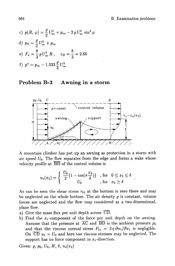
Problem B-3 Awning in a storm
D -----~-------
p= const control volume
awning H
Xz
B Examination problems
/
A mountain climber has put up an awning as protection in a storm with air speed Uo. The flow separates from the edge and forms a wake whose velocity profile at BD of the control volume is
As can be seen the shear stress 721 at the bottom is zero there and may be neglected on the whole bottom. The air density (! is constant, volume forces are neglected and the flow may considered as a two-dimensional, plane flow. a) Give the mass flux per unit depth across CD. b) Find the xl-component of the force per unit depth on the awning.
Assume that the pressure at AC and BD is the ambient pressure Po and that the viscous normal stress Pll = 2 Tf 8uI/8xI is negligible. On CD UI = Uo and here too viscous stresses may be neglected. The support has no force component in Xl-direction.
Given: (!, Po, Uo, H, 8, Uo(X2)
565
Solution 1
a) mCD = '2 (JUob
b) (P. .. awning) Xl = (J U6 ~
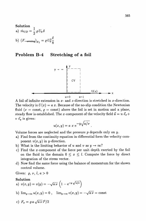
Problem B-4 Stretching of a foil
y y --> 00 1--1
I I I I I cv I I I I I L __ ~ U(x)
~--------------~------------~~~--~x x=O x=l
A foil of infinite extension in x- and z-direction is stretched in x-direction. The velocity is U(x) = a x. Because of the no-slip condition the Newtonian fluid (v = const, (J = const) above the foil is set in motion and a plane, steady flow is established. The x-component of the velocity field 11 = u ex + v ey is given:
u(x, y) = a x e -yJa/v .
Volume forces are neglected and the pressure p depends only on y. a) Find from the continuity equation in differential form the velocity com
ponent v(x,y) in y-direction. b) What is the limiting behavior of u and v as y ---+ oo? c) Find the x-component of the force per unit depth exerted by the foil
on the fluid in the domain 0 :::; x :::; l. Compute the force by direct integration of the stress vector.
d) Now find the same force using the balance of momentum for the shown control volume.
Given: (J, v, I, a > 0
Solution a) v(x, y) = v(y) = -0iV (1 - e-Y#) b) limy-+oou(x,y) = 0, liffiy-+oov(x,y) = -0iV = const
566 B Examination problems
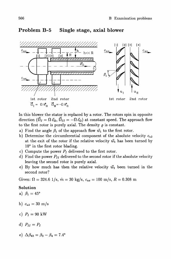
Problem B-5 Single stage, axial blower
1st rotor 2nd rotor
Or = 0 eo 0n=-O eo
[1] [2] [3] [4]
1st rotor 2nd rotor
In this blower the stator is replaced by a rotor. The rotors spin in opposite direction (01 = 0 en, OIl = -0 en) at constant speed. The approach flow to the first rotor is purely axial. The density (! is constant. a) Find the angle (31 of the approach flow tih to the first rotor. b) Determine the circumferential component of the absolute velocity Cu 2
at the exit of the rotor if the relative velocity WI has been turned by 10° in the first rotor blading.
c) Compute the power PI delivered to the first rotor. d) Find the power PIl delivered to the second rotor if the absolute velocity
leaving the second rotor is purely axial. e) By how much has then the relative velocity WI been turned in the
second rotor?
Given: 0 = 324.6 l/s, m = 30 kg/s, Cax = 100 mis, R = 0.308 m
Solution a) (31 = 45°
b) Cu 2 = 30 m/s
c) PI = 90 kW
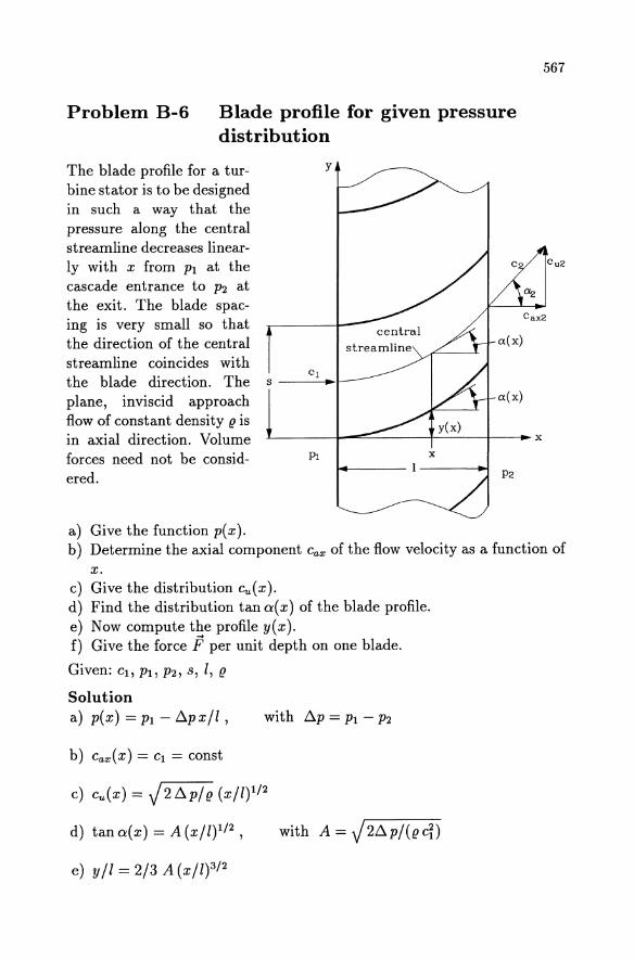
Problem B-6 Blade profile for given pressure distribution
The blade profile for a turbine stator is to be designed in such a way that the pressure along the central streamline decreases linearly with x from PI at the cascade entrance to P2 at the exit. The blade spacing is very small so that the direction of the central streamline coincides with
y
Cl the blade direction. The s ---~+-~ plane, inviscid approach flow of constant density u is in axial direction. Volume forces need not be considered.
a) Give the function p(x).
L----~~----r--_+-~x
PI
567
b) Determine the axial component Cax of the flow velocity as a function of x.
c) Give the distribution cu(x). d) Find the distribution tan a( x) of the blade profile. e) Now compute the profile y(x). f) Give the force F per unit depth on one blade.
Given: CI, PI, P2, S, 1, u
Solution a) p(x) = PI - t::..px/l , with t::..p = PI - P2
b) Cax ( x) = CI = const
c) cu(x) = J2t::..p/u (x/l)I/2
d) tan a(x) = A (X/l)I/2 , with A = J2t::..p/(ucD
e) y/l = 2/3 A (X/W/2
568 B Examination problems
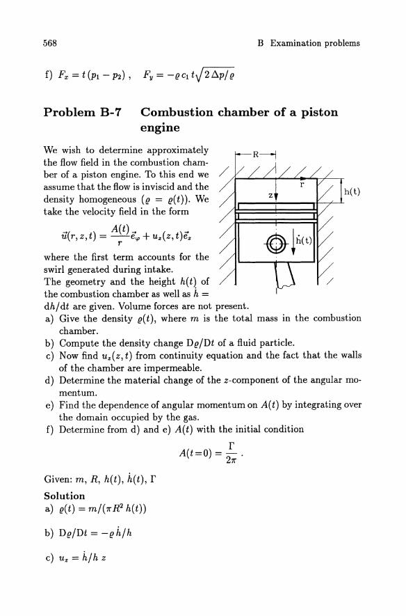
Problem B-7 Combustion chamber of a piston . engine
We wish to determine approximately the flow field in the combustion chamber of a piston engine. To this end we assume that the flow is inviscid and the density homogeneous (g = g(t)). We take the velocity field in the form
.... ( ) A(t).... () .... ur,z,t =--ecp+uzz,tez r
where the first term accounts for the swirl generated during intake. The geometry and the height h(t) of the combustion chamber as well as h = dh/dt are given. Volume forces are not present.
h(t)
a) Give the density g(t), where m is the total mass in the combustion chamber.
b) Compute the density change Dg/Dt of a fluid particle. c) Now find uz(z, t) from continuity equation and the fact that the walls
of the chamber are impermeable. d) Determine the material change of the z-component of the angular mo
mentum. e) Find the dependence of angular momentum on A(t) by integrating over
the domain occupied by the gas. f) Determine from d) and e) A(t) with the initial condition
Given: m, R, h(t), h(t), r Solution a) g(t) = m/(1l'R2 h(t))
b) Dg/Dt = -gh/h
c) U z = h/h z
r A(t=O) = -.
21l'
569
D d) Dt(Dz ) = 0
e) Dz = A(t) m
f) A=fj(211")
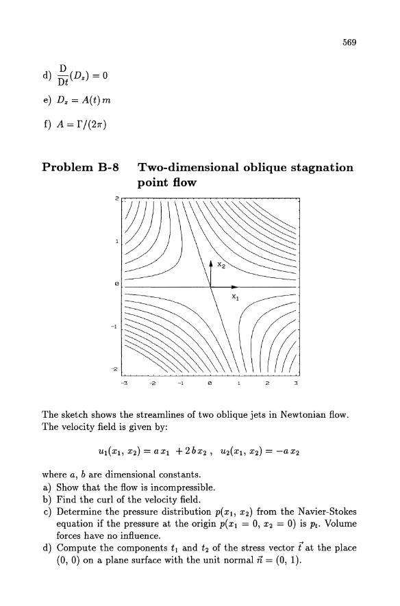
Problem B-8 Two-dimensional oblique stagnation point flow
o ______________ ~\ __ ~ __ -----------
-3 -2 -1 o 2 3
The sketch shows the streamlines of two oblique jets in Newtonian flow. The velocity field is given by:
where a, b are dimensional constants. a) Show that the flow is incompressible. b) Find the curl of the velocity field. c) Determine the pressure distribution p(Xl, X2) from the Navier-Stokes
equation if the pressure at the origin P(Xl = 0, X2 = 0) is Pt. Volume forces have no influence.
d) Compute the components tl and t2 of the stress vector t at the place (0, 0) on a plane surface with the unit normal ii = (0, 1).
570 B Examination problems
e) Find the pathline in parameter form and then explicit X2 = f(xI). Give the equation for the streamlines.
Given: (!, 'f/, a, b, Pt
Solution b) curl u = - 2 b e3
2
c) P(Xl' X2) = Pt - (! ~ (X~ + x~) d) t1(O, 0) = 2'f/ b, t2(0, 0) = -Pt - 2'f/ a
a with D = -AC
b
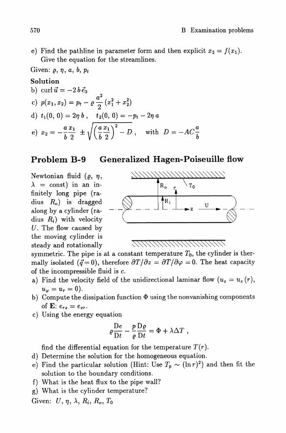
Problem B-9 Generalized Hagen-Poiseuille flow
Newtonian fluid ((!, 'f/, >. = const) in an infinitely long pipe (radius Ro) is dragged along by a cylinder (radius Ri) with velocity U. The flow caused by the moving cylinder is
u
steady and rotationally ~~~~~~~~~"0. symmetric. The pipe is at a constant temperature To, the cylinder is thermally isolated (cf=O), therefore 8T/8z = 8T/8cp =0. The heat capacity of the incompressible fluid is c. a) Find the velocity field of the unidirectional laminar flow (u z = U z (r),
Ucp = U r = 0). b) Compute the dissipation function cI> using the nonvanishing components
of E: erz = ezr •
c) Using the energy equation
De P D(! (!- - -- = cI> + >'I:l.T
Dt (! Dt
find the differential equation for the temperature T(r). d) Determine the solution for the homogeneous equation. e) Find the particular solution (Hint: Use Tp '" (In r )2) and then fit the
solution to the boundary conditions. f) What is the heat flux to the pipe wall? g) What is the cylinder temperature?
Given: U, 'f/, >., R;, Ro , To
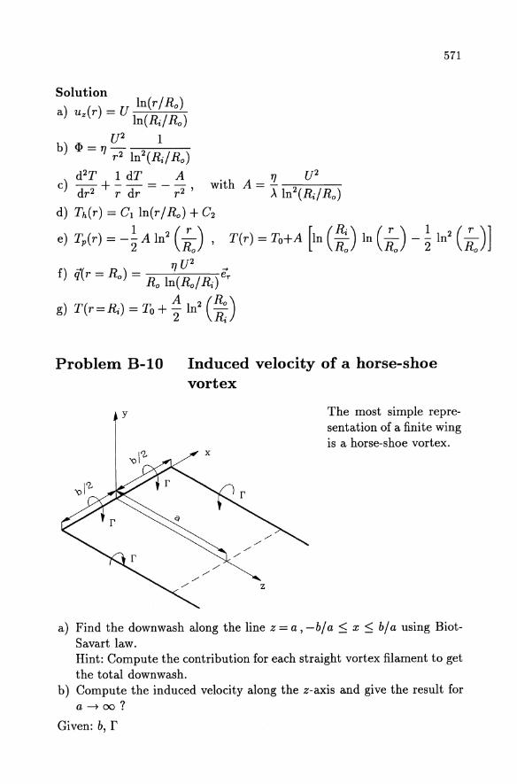
Problem B-IO
y
Induced velocity of a horse-shoe vortex
571
The most simple representation of a finite wing is a horse-shoe vortex.
a) Find the downwash along the line z = a, -b/a :::; x ~ b/a using BiotSavart law. Hint: Compute the contribution for each straight vortex filament to get the total downwash.
b) Compute the induced velocity along the z-axis and give the result for a-+oo?
Given: b, r
572 B Examination problems
Solution a) il = - (Iill(l) + lilb) + lilb)) ey , with
b)
lill(l) = r 1 (1 a ) 411" b/2 + x + ja2 + (b/2 + x)2
lill(2) = r 1 ( b/2 - x b/2 + x )
411" ~ ja2 + (b/2 - x)2 + ja2 + (b/2 + X)2
lilb) = - 1+ r 1 ( a ) 411" b/2-x ja2+(b/2-x)2'
il(x=O, a) = -~ (~ + ~ . la2 + (b/2)2) e , 47r babY y
il(x=O,a -t 00) 2f ~
--e 11" b y
(1)
(2)
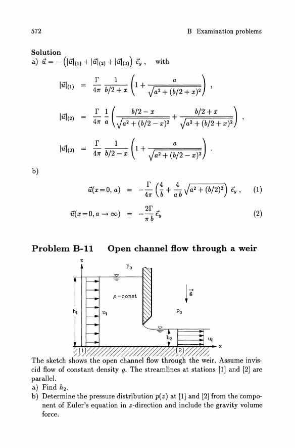
Problem B-11 Open channel How through a weir z
Po
p=const
Po
f----+j U2
~/~[1+]~~~~~~~~/~/[2~]~~//~X /// //// //
The sketch shows the open channel flow through the weir. Assume invis-cid flow of constant density (!. The streamlines at stations [1 J and [2J are parallel. a) Find h2 •
b) Determine the pressure distribution p( z) at [1 J and [2J from the component of Euler's equation in z-direction and include the gravity volume force.
573
c) Does the ambient pressure Po make a contribution to the force in xdirection?
d) Compute the force Fx per unit depth on the weir.
Given: Po, g, hI, UI, U2, 9
Solution
a) h2 = UI hI U2
b) PI = Po + g 9 (hI - z), P2 = Po + g 9 (h2 - z)
c) No
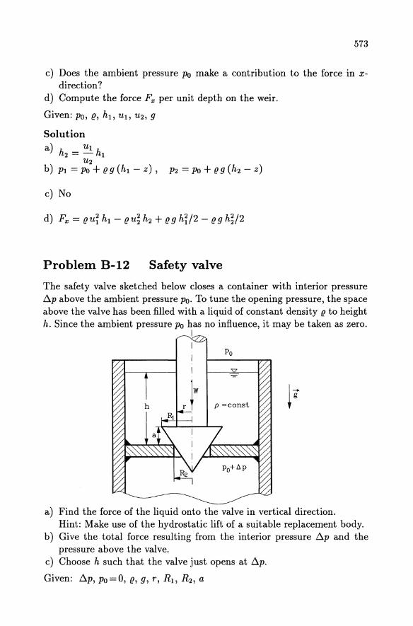
Problem B-12 Safety valve
The safety valve sketched below closes a container with interior pressure /j,p above the ambient pressure Po. To tune the opening pressure, the space above the valve has been filled with a liquid of constant density g to height h. Since the ambient pressure Po has no influence, it may be taken as zero.
I
Po
-
h P =const ~g
a) Find the force of the liquid onto the valve in vertical direction. Hint: Make use of the hydrostatic lift of a suitable replacement body.
b) Give the total force resulting from the interior pressure /j,p and the pressure above the valve.
c) Choose h such that the valve just opens at /j,p.
Given: /j,p, Po=O, g, g, r, RI , R2 , a
574 B Examination problems
Solution a) Fz = (!g [-h7l" (R~ - r2) - a7l"r2 + 7l"/3 a(R~ + Rl R2 + RDl
b) Fz tot = Fz + ~ P 7l" R~
c) h= (~P7l"R~-W)/((!g)-a7l"r2+7l"/3a(Ri+RIR2+RD 7l" (R~ - r2 )
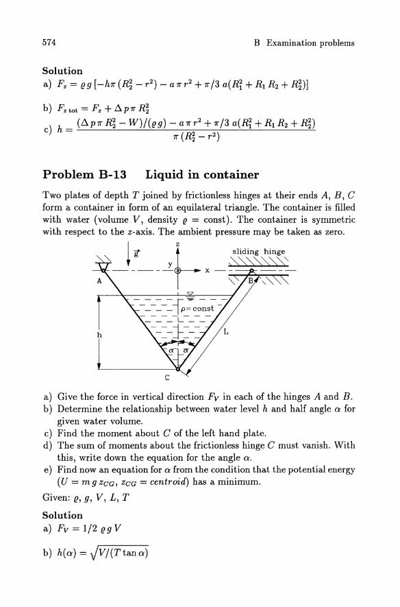
Problem B-13 Liquid in container
Two plates of depth T joined by frictionless hinges at their ends A, B, C form a container in form of an equilateral triangle. The container is filled with water (volume V, density (! = const). The container is symmetric with respect to the z-axis. The ambient pressure may be taken as zero.
'" t y ~~~"'0"\ " ------ x -- ---
I g f-Z sliding hinge
A , 8 ~
h
a) Give the force in vertical direction Fv in each of the hinges A and B. b) Determine the relationship between water level h and half angle a for
given water volume. c) Find the moment about C of the left hand plate. d) The sum of moments about the frictionless hinge C must vanish. With
this, write down the equation for the angle a. e) Find now an equation for a from the condition that the potential energy
(U = m 9 ZCG, ZCG = centroid) has a minimum.
Given: (!, g, V, L, T
Solution a) Fv = 1/2 (! 9 V
b) h(a) = JV/(T tan a)
575
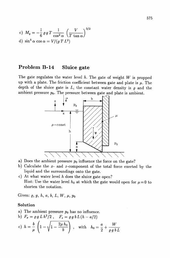
Problem B-14 Sluice gate
The gate regulates the water level h. The gate of weight W is propped up with a plate. The friction coefficient between gate and plate is fl. The depth of the sluice gate is L, the constant water density is g and the ambient pressure Po. The pressure between gate and plate is ambient.
z I; ~_b_-... • Po
x
p=const
h
Po
'" a) Does the ambient pressure Po influence the force on the gate? b) Calculate the x- and z-component of the total force exerted by the
liquid and the surroundings onto the gate. c) At what water level h does the sluice gate open?
Hint: Use the water level ho at which the gate would open for fl = 0 to shorten the notation.
Given: g, g, h, a, b, L, W, fl, Po
Solution
a) The ambient pressure Po has no influence. b) Fx =ggLh2 /2, Fz =ggbL(h-a/2)
b(.~ . c) h =; 1 - VI - -----z;--b-) , wIth a W
ho=-+--2 ggbL
576 B Examination problems
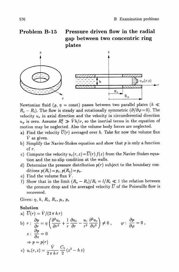
Problem B-15 Pressure driven flow in the radial gap between two concentric ring plates
z z
------ h
r
Newtonian fluid (g, 'T/ = const) passes between two parallel plates (h ~ Ro - R;). The flow is steady and rotationally symmetric (8j8rp=0). The velocity U z in axial direction and the velocity in circumferential direction Ucp is zero. Assume R; ~ Vhjv, so the inertial terms in the equation of motion may be neglected. Also the volume body forces are neglected. a) ~ind the velocity U(r) averaged over h. Take for now the volume flux
F as given. b) Simplify the N avier-Stokes equation and show that P is only a function
of r. c) Compute the velocity ur(r, z) =U(r) J(z) from the Navier-Stokes equa
tion and the no-slip condition at the walls. d) Determine the pressure distribution p(r) subject to the boundary con
ditions p(Ri) = Pi, p(Ro) = Po· e) Find the volume flux V. f) Show that in the limit (Ro - Ri)j Ri = lj Ri ~ 1 the relation between
the pressure drop and the averaged velocity U of the Poiseuille flow is recovered.
Given: 'T/, h, Ri, Ro, Pi, Po
Solution a) U(r) = Vj(27rhr)
b) r: 8p = 'T/ (82Ur + ~ 8ur _ Ur 82ur) # 0 , 8r 8r2 r 8r r2 8z2 8p
z: -=0 8z
=> p = p(r) . V C1 2
c) Ur (r, z) = 2 7r h r 2 (z - h z)
8p rp: -=0,
8rp
577
In(r/ R;) d) p(r) = (Po - Pi) In(Ro / Ri) + Pi
V = 7r h3 Pi - Po e) 617 In(Ro/ Ri )
f) Pi - Po = U 12 17 I h2
Problem B-16 Pressure driven channel flow with variable viscosity
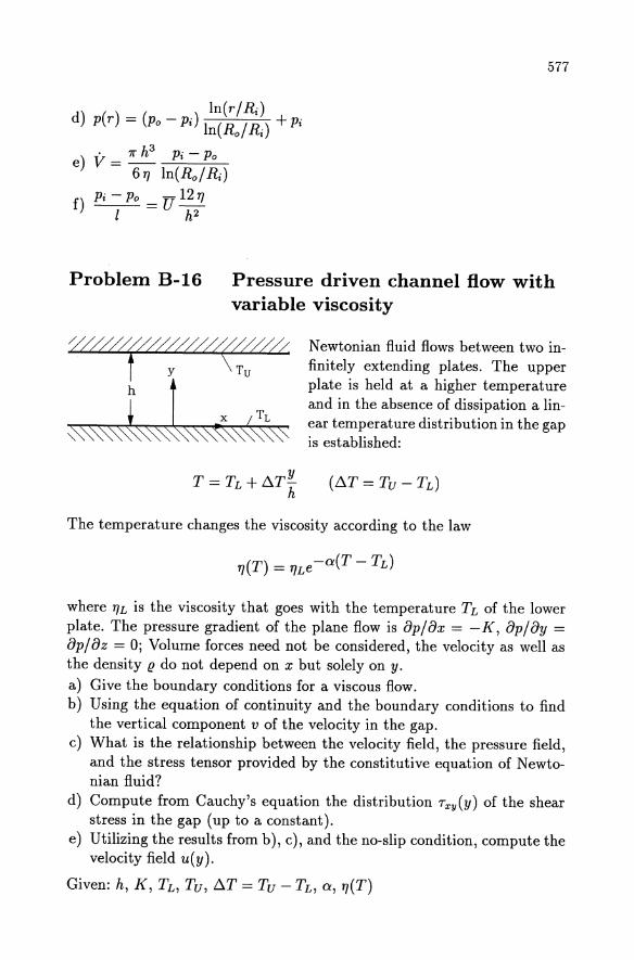
-////ij~/uu//~/ffi y Tu
~~t~t~~~~~ Newtonian fluid flows between two infinitely extending plates. The upper plate is held at a higher temperature and in the absence of dissipation a linear temperature distribution in the gap is established:
(!::"T = Tv - TL)
The temperature changes the viscosity according to the law
where 17L is the viscosity that goes with the temperature TL of the lower plate. The pressure gradient of the plane flow is op/ox = -K, op/oy = op/ oz = 0; Volume forces need not be considered, the velocity as well as the density (! do not depend on x but solely on y.
a) Give the boundary conditions for a viscous flow. b) Using the equation of continuity and the boundary conditions to find
the vertical component v of the velocity in the gap. c) What is the relationship between the velocity field, the pressure field,
and the stress tensor provided by the constitutive equation of Newtonian fluid?
d) Compute from Cauchy's equation the distribution Txy(y) of the shear stress in the gap (up to a constant).
e) Utilizing the results from b), c), and the no-slip condition, compute the velocity field u(y).
Given: h, K, TL, Tv, !::"T = Tv - TL, a, 17(T)
578 B Examination problems
Solution a) No-slip condition: u(y = 0) = 0, u(y = h) = 0 ,
1. e. y = 0 : u = v = 0; y = h : u = v = 0 b) v == 0
c) T xx = Tyy = - P ,
d) Txy = -K y + C1
8u Txy = Tyx = 'TI-
8y
e) u(y) = ~ K h2 {eOit:.T y/h - 1 _ JL eOit:.TY1h}
'TIL a t::..T 1 - e-Oi t:.T h
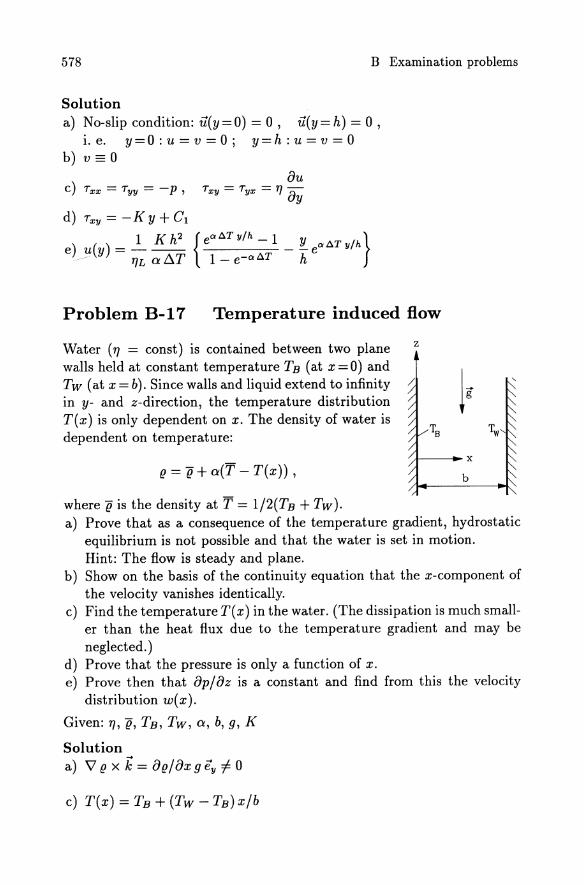
Problem B-17 Temperature induced flow
Water ('TI = const) is contained between two plane walls held at constant temperature TB (at x=O) and Tw (at x = b). Since walls and liquid extend to infinity in y- and z-direction, the temperature distribution T( x) is only dependent on x. The density of water is dependent on temperature:
(! = g+ a(T - T(x)) ,
where g is the density at T = 1/2(TB + Tw).
z
/
A----__ x
b
a) Prove that as a consequence of the temperature gradient, hydrostatic equilibrium is not possible and that the water is set in motion. Hint: The flow is steady and plane.
b) Show on the basis of the continuity equation that the x-component of the velocity vanishes identically.
c) Find the temperature T( x) in the water. (The dissipation is much smaller than the heat flux due to the temperature gradient and may be neglected. )
d) Prove that the pressure is only a function of x. e) Prove then that 8p/8z is a constant and find from this the velocity
distribution w( x).
Given: 'TI, g, TB, Tw, a, b, g, K
Solution a) \7 (! X k = 8(!/8xgey f= 0
c) T(x) = TB + (Tw - TB) x/b
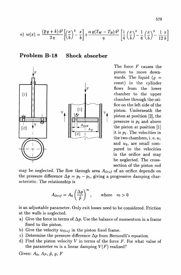
Problem B-18 Shock absorber
[1]
579
The force F causes the piston to move downwards. The liquid (g =
const) in the cylinder flows from the lower chamber to the upper chamber through the orifice on the left side of the
vt
Vt
piston. Underneath the piston at position [2], the pressure is P2 and above the piston at position [1 J
[2] it is Pl. The velocities in the two chambers, i. e. Ul
and U2, are small compared to the velocities in the orifice and may be neglected. The crosssection of the piston rod
may be neglected. The flow through area AOriJ of an orifice depends on the pressure difference b..p = P2 - PI, giving a progressive damping characteristic. The relationship is
( b..p)m AOriJ = Ao T ' where m > 0
is an adjustable parameter. Only exit losses need to be considered. Friction at the walls is neglected. a) Give the force in terms of b..p. Use the balance of momentum in a frame
fixed to the piston. b) Give the velocity WOriJ in the piston fixed frame. c) Determine the pressure difference b..p from Bernoulli's equation. d) Find the piston velocity V in terms of the force F. For what value of
the parameter m is a linear damping V(F) realized?
Given: Ao, Ap , p, g, F
580 B Examination problems
Solution a) F = b..pAp
Ap (b..p,p)-m b) WOri! = V Ao ~
1
c) b..p = P (~ i V 2 (~: r) 2m+l
( F )m+l/2 fiP Ao
d) V = Ap P V g Ap
::::} linear damping for m = 1/2.
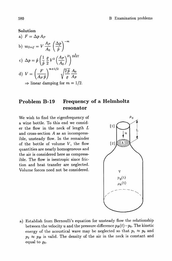
Problem B-19 Frequency of a Helmholtz resonator
We wish to find the eigenfrequency of a wine bottle. To this end we consider the flow in the neck of length L and cross-section A as an incompressible, unsteady flow. In the remainder of the bottle of volume V, the flow quantities are nearly homogeneous and the air is considered here as compressible. The flow is isentropic since friction and heat transfer are neglected. Volume forces need not be considered.
Po
-----------., /' ~
I '
a) Establish from Bernoulli's equation for unsteady flow the relationship between the velocity u and the pressure difference PB(t)-PO' The kinetic energy of the acoustical wave may be neglected so that Pl ~ Po and P2 ~ PB is valid. The density of the air in the neck is constant and equal to (lo.
581
b) From the continuity equation, find the relationship between u and the change of density (!B(t) in the bottle. (To do this compute the mass flux at [2] using (! = (!o!)
c) Replace the density change from b) by the pressure change using the definition of the sound speed. In the bottle the sound speed is aB ~ const.
d) Insert the pressure change into the differential equation from part a) and give the eigenfrequency w of this homogeneous equation.
e) Give the frequency f of the oscillator for the values V = 0.75 1, A =
5 cm2 , L = 5 cm, aB = 370 mls ?
Given: (!o, Po, V = 0.751, A = 5 cm2 , L = 5 cm, aB = 370 mls Solution du
a) PB(t) - Po = -(!o L dt
d{!B b) V dt = (!ouA
dPB 2 c) V cit = (!OaB uA
d2u d) dt2 + w2u = 0 , . h Ja1A
WIt w = V L
e) f = 215 Hz
582 B Examination problems
Problem B-20 Chamber and exhaust pipe of an internal combustion engine
The sketch shows piston, cylinder, and exhaust pipe. During exhaust, the piston moves upward driven by the crankshaft rotating at angular speed O. The piston pushes the fluid of constant density f! through the open exhaust valve into the pipe and in the surroundings. During exhaust the valve remains in the open position. The flow cross-section changes from AE (positon [ED to the cross-section of the pipe A (The thickness of the valve stem is neglected.). The ambient pressure Po is constant. The piston area Ap, the exit area AE of the valve and the pipe cross-section are all known. The distance between cylinder head and piston may be described by the relation h(t) = ho + r (1 -cos 0 t). The pressure losses of this unsteady flow may be approximately described by the corresponding losses in steady flow. Pressure
Po
losses by wall friction and volume forces are neglected. a) Find the piston velocity Up,
b) the velocity UE at [E] and the velocity U in the pipe.
stem
c) Calculate the pressure loss D.Pl of the flow from the cylinder to the surroundings.
d) Give the pressure difference D.p = P2 - Po as the piston pushes the fluid to the outside. Hint: Since A ~ A p , the velocity in the chamber may be neglected. Furthermore it is sufficient to account for the change with time of the velocity in the exhaust pipe only.
Given: Ap, A, (with A ~ Ap), AE, r, L, 0, Po, f!
Solution a) Up = -rO sin Ot
b) UE = - ~: rOsin 0 t , Ap n . n
U = - A r H SIn H t
) f!(. 2 [(Ap)2 ( AE)2 (Ap)2] C b..Pl = 2" r 0 sm 0 t) AE 1 - A + A
A [(AAEP )2 (1 _ AAE) 2 + (AAP )2] d) P2-PO = - f! L : r 0 2 cos 0 t+~ (r 0 sin 0 t)2
583
Problem B-21 Pump-turbine storage plant
The sketch shows a pump-turbine storage plant, consisting of a lower reservoir, an upper reservoir with a distance between head water level and tail gate level of H = 250 m, a duct (length L = 350 m, diameter d = 0.5 m, roughness k/d = 2*10-4 ) and a pump-turbine with an efficiency of 17p = 0.8 in the pump mode and an efficiency of 17T = 0.9 in the turbine mode. In times of low demand the water (density (! = 103 kg/ m3 , kinematic viscosity v = 10-6 m2 / s) is pumped from the lower reservoir into the upper. The volume flux is Vp = 0.393 m3 / s. In times of high demand the flow direction is reversed and operation is in turbine mode. The volume flux in turbine mode is 1.4 times that in pump mode: VT = 1.4 Vp = 0.55 m3 / s. a) Find the average velocity U and Reynolds number Re in the duct for
both turbine and pump mode. b) Compute the pressure losses LlPlD in the duct for both operation modes. c) What are the exit losses LlPIE in both modes? d) What ppwer must be supplied to the fluid and what power is required
for the pump-turbine? e) Give the power of the fluid in turbine mode and the shaft power of the
turbine. f) Find the hydraulic efficiency 17h of the plant, i. e. the ratio of rejected
turbine power to required pump power for the same volume flux.
Given: 9 = 9.81 m/s2 , H = 250 m, L = 350 m, d = 0.5 m, k/d = 2 * 10-4 ,
17p = 0.8, 17T = 0.9, (! = 103 kg/m3 , v = 10-6 m2/s, Vp = 0.393 m3 /s,
584
VT = 1.4 Vp = 0.55 m3 /s Solution a) to e)
pump turbine
f) 1Jh = 0.70
B Examination problems
Re I b.PID [bar] I b.P1E [bar] I Padd/rej [kW]
1.0 * 106 0.206 0.020 1216 1.4 * 106 0.390 0.039 1193
Problem B-22 Overexpanded Laval nozzle
[3] Pitot-tube
o L
Pl3
Ideal gas flows from a large reservoir with total pressure PtR through a Laval nozzle into a pipe with constant cross-section A3 •
For the divergent part of the Laval nozzle, the cross-sectional area distribution is
A normal shock wave is positioned at x = Xs. The flow is steady and with exception of the shock itself isentropic. At [3] the total pressure Pt3 = 1.2 bar has been measured using a Pitot-tube. a) Find the Mach number Ml in front of a shock positioned at Xs = 0.8 L.
Determine the Mach number behind the shock and the ratio of total pressure Pt2/Ptl across the shock.
b) What is the reservoir pressure PtR for a total pressure Pt3 = 1.2 bar measured at [3]? Calculate the pressure p* at the throat of the nozzle.
c) Find the new reference area A; after the shock, the Mach number M3 and the pressure P3.
585
d) Calculate the x-component of the force acting on the nozzle between the throat and position [3]. Use the balance of momentum from stream filament theory and remember that for ideal gas we have gu2 = 1M2 p. Give the relationship Fx/(p* A*).
Given: L, A*, A3 = 3A*, I = 1.4, Pt3 = 1.2 bar
Solution a) Ml = 1.97 , M2 = 0.582 , Pt2/Ptl = 0.735
b) PtR = 1.633 bar, p* = 0.862 bar
c) A; = 1.353 A*, M3 = 0.27, P3 = 1.14 bar
) Fx P3 2 d -A = I + 1- 3 - (t M3 + 1) = -1.972
p* * p*
Problem B-23 Nozzle inlet
The inlet of a supersonic nozzle is exposed to a supersonic stream of an ideal gas with Mach number Ml = 3. A shock has positioned itself ahead of the inlet. At the central streamline the shock is a normal shock. The flow is isentropic with the exception of the shock itself.
The cross-sectional area of the throat at position [3] is A = 0.2m2 . Downstream of the throat and in the divergent part of the nozzle the Mach number at position [4] is larger than one. The total temperature Ttl and pressure Ptl at position [1] are gIVen.
a) Calculate the temperature Tl and velocity Ul at [1]. b) Calculate the Mach number M2, pressure P2, and the velocity U2 behind
the shock. c) Find the Mach number M3 at [3], further the velocity U3, temperature
T3, and pressure P3. d) How large is the mass flux m through the nozzle?
Given: I = 1.4, R = 287 J/kgK, Ml = 3, Ptl = 1 bar, Ttl A = 0.2 m2
295 K,
586 B Examination problems
Solution
a) TI = 105.4 K, UI = 617.3 m/s
b) M2 = 0.475, P2 = 0.28 bar, U2 = 159.9 m/s
c) M3 = 1, U3 = 314.3 mis, T3 = 245.9 K, P3 = 0.173 bar
d) m = 15.41 kg/s
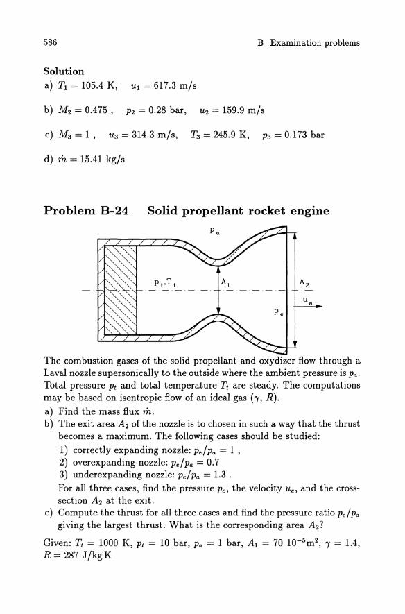
Problem B-24 Solid propellant rocket engine
The combustion gases of the solid propellant and oxydizer flow through a Laval nozzle supersonically to the outside where the ambient pressure is Pa. Total pressure Pt and total temperature Tt are steady. The computations may be based on isentropic flow of an ideal gas (-y, R). a) Find the mass flux m. b) The exit area A2 of the nozzle is to chosen in such a way that the thrust
becomes a maximum. The following cases should be studied:
1) correctly expanding nozzle: Pe / Pa = 1 , 2) overexpanding nozzle: Pe/Pa = 0.7 3) underexpanding nozzle: Pe/Pa = 1.3 . For all three cases, find the pressure Pe, the velocity Ue, and the crosssection A2 at the exit.
c) Compute the thrust for all three cases and find the pressure ratio Pe/Pa giving the largest thrust. What is the corresponding area A2?
Given: Tt = 1000 K, Pt = 10 bar, Pa = 1 bar, Al = 70 1O-5m2, 'Y = 1.4, R = 287 J/kgK
587
Solution a) m = 0.895 kg/s b) c)
Pa/Pe /I Pe [barJ I U e [m/sJ I A2 [m2J I F [NJ 1 1 985 135 10 5 881
0.7 0.7 1035 16710-5 876 1.3 1.3 942 117 10-5 878
::::} A2 = 13510-5 m 2
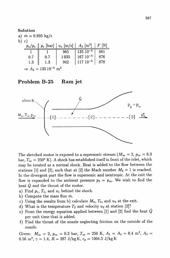
Problem B-25 Ram jet
shock
--Moo, Too, Poo . _. -[1]- ----- - -[2J- - - - -- --[3J ~
The sketched motor is exposed to a supersonic stream (Moo = 2, Poo = 0.3 bar, Too = 2500 K). A shock has established itself in front ofthe inlet, which may be treated as a normal shock. Heat is added to the flow between the stations [1 J and [2J, such that at [2J the Mach number M2 = 1 is reached. In the divergent part the flow is supersonic and isentropic. At the exit the flow is expanded to the ambient pressure P3 = Poo. We wish to find the heat Q and the thrust of the motor. a) Find PI, Tl, and UI behind the shock. b) Compute the mass flux m. c) Using the results from b) calculate M3 , T3 , and U3 at the exit. d) What is the temperature T2 and velocity U2 at station [2J? e) From the energy equation applied between [1 J and [2J find the heat Q
per unit time that is added. f) Find the thrust of the nozzle neglecting friction on the outside of the
nozzle.
Given: Moo = 2, Poo = 0.3 bar, Too = 250 K, Al = A2 = 0.4 m 2 , A3 =
0.56 m 2, I = 1.4, R = 287 J/kgK, cp = 1004.5 J/kgK
588 B Examination problems
Solution a) PI = 1.35 bar, TI = 421.8 K, UI = 237.5 m/s
b) m = 106 kg/s
c) M3 = 1.76, T3 = 379.9 K, U3 = 687.6 m/s
d) T2 = 512.9 K, U2 = 454.0 m/s
e) Q = 17630 kJ/s
f) § = -5692 N ex
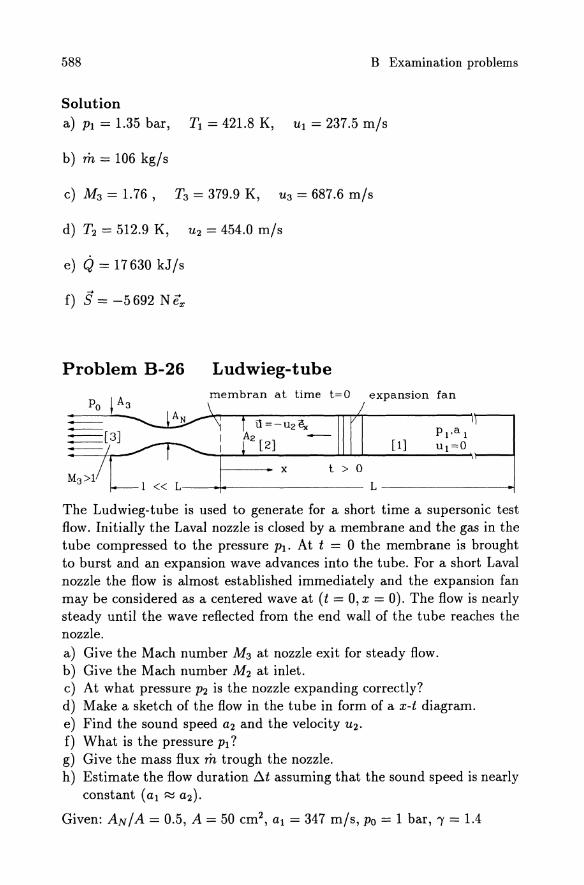
Problem B-26 Ludwieg-tube membran at time t=O expansion fan
[1]
x t > 0
---I----------L----------i
The Ludwieg-tube is used to generate for a short time a supersonic test flow. Initially the Laval nozzle is closed by a membrane and the gas in the tube compressed to the pressure Pl' At t = 0 the membrane is brought to burst and an expansion wave advances into the tube. For a short Laval nozzle the flow is almost established immediately and the expansion fan may be considered as a centered wave at (t = 0, x = 0). The flow is nearly steady until the wave reflected from the end wall of the tube reaches the nozzle. a) Give the Mach number M3 at nozzle exit for steady flow. b) Give the Mach number M2 at inlet. c) At what pressure P2 is the nozzle expanding correctly? d) Make a sketch of the flow in the tube in form ofax-t diagram. e) Find the sound speed a2 and the velocity U2'
f) What is the pressure PI? g) Give the mass flux m trough the nozzle. h) Estimate the flow duration /)"t assuming that the sound speed is nearly
constant (al ~ a2)'
Given: AN/A = 0.5, A = 50 cm2, al = 347 m/s, Po = 1 bar, I = 1.4
Solution
a) M3 = 2.2 b) M2 = 0.3 c) P2 = 10.05 bar d) x-t diagram
t
[ 1]
tube
end
589
o x o L
e) a2 = 327.4 mis, U2 = 98.2 m/s f) PI = 15.1 bar g) m = 6.446 kg/s h) tit ~ 2 L/al
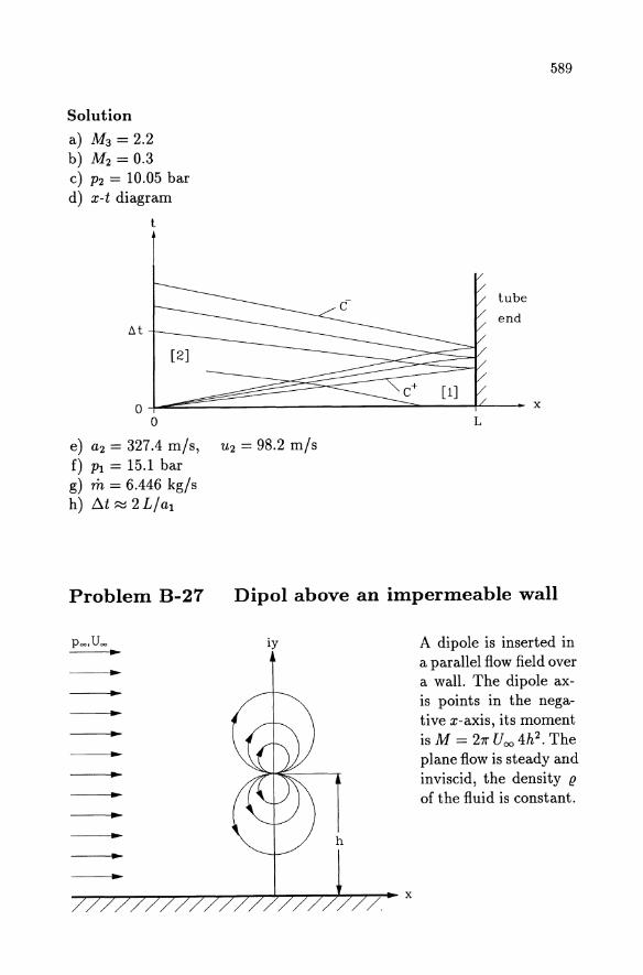
Problem B-27 Dipol above an impermeable wall
iy A dipole is inserted in a parallel flow field over a wall. The dipole axis points in the negative x-axis, its moment is M = 271" Uoo 4h2 . The plane flow is steady and inviscid, the density {!
of the fluid is constant.
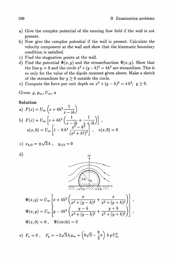
590 B Examination problems
a) Give the complex potential of the ensuing flow field if the wall is not present.
b) Now give the complex potential if the wall is present. Calculate the velocity component at the wall and show that the kinematic boundary condition is satisfied.
c) Find the stagnation points at the wall. d) Find the potential <I> (x, y) and the streamfunction \lI(x, y). Show that
the line y = 0 and the circle x2 + (y - h)2 = 4h2 are streamlines. This is so only for the value of the dipole moment given above. Make a sketch of the streamlines for y :2: 0 outside the circle.
e) Compute the force per unit depth on x2 + (y - h)2 = 4h2; y:2: o.
Given: e, POC)) Uoo , a
c) Xl/2 = ±.J3 h, Yl/2 = 0
d) iy
<I>(x,y) = Uoo [x + 4h2 (x2 + (~_ h)2 + x2 + (~+ h)2)] ,
\lI(x,Y)=Uoo[Y-4h2(X2:(~~h)2+ X2:(;~h)2)]' \lI(x,O) = 0, \lI(circle) = 0
591
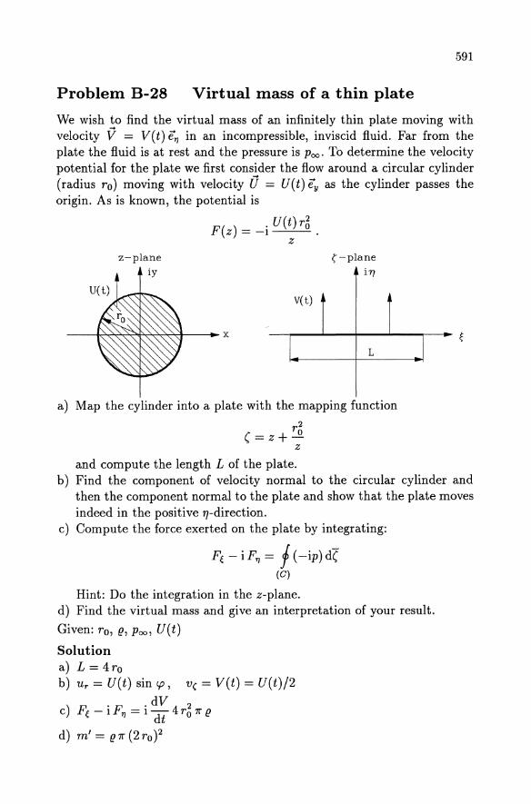
Problem B-28 Virtual mass of a thin plate
We wish to find the virtual mass of an infinitely thin plate moving with velocity V = V(t) ETJ in an incompressible, inviscid fluid. Far from the plate the fluid is at rest and the pressure is Poo. To determine the velocity potential for the plate we first consider the flow around a circular cylinder (radius ro) moving with velocity 0 = U(t) Ey as the cylinder passes the origin. As is known, the potential is
z-plane iy
F(z) = -i U(t) r~ . z
V(t)
I
(-plane
i1)
L
a) Map the cylinder into a plate with the mapping function
r2 (=z+...Q
z
and compute the length L of the plate.
I
b) Find the component of velocity normal to the circular cylinder and then the component normal to the plate and show that the plate moves indeed in the positive 1]-direction.
c) Compute the force exerted on the plate by integrating:
Fe - iFTJ = f (-ip)d( (C)
Hint: Do the integration in the z-plane. d) Find the virtual mass and give an interpretation of your result.
Given: ro, (!, Poo, U(t)
Solution a) L = 4ro b) U r = U(t) sin cp, v( = V(t) = U(t)/2
) F . F . dV 4 2 C e - 1 TJ = 1 dt rO 7r (!
d) m' = (!7r (2rO)2
592 B Examination problems
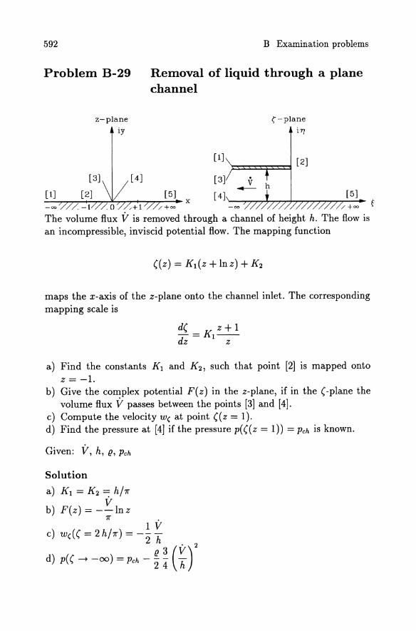
Problem B-29 Removal of liquid through a plane channel
z-plane
iy
[ 4]
[5]
[1]
[3]
x [ 4]
(-plane
iry
[2]
h [5]
maps the x-axis of the z-plane onto the channel inlet. The corresponding mapping scale is
a) Find the constants Kl and K 2 , such that point [2] is mapped onto z =-1.
b) Give the complex potential F( z) in the z-plane, if in the (-plane the volume flux V passes between the points [3] and [4].
c) Compute the velocity w( at point ((z = 1). d) Find the pressure at [4] if the pressure p(((z = 1)) = Pch is known.
Given: V, h, (!, Pch
Solution
a) Kl = K2 =: h/7r V
b) F(z) = --lnz 7r •
1 V c) W((( = 2 h/7r) = -- -
2 h . 2
d) p(( --t -00) = Pch - ~ ~ (~)
Problem B-30
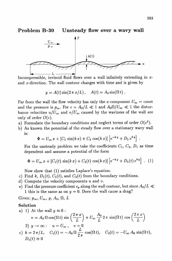
.. Unsteady flow over a wavy wall
y
~---L------.I
593
Incompressible, inviscid fluid flows over a wall infinitely extending in x-and z-direction. The wall contour changes with time and is given by
y=A(t)sin(27rx/L), A(t)=Aosin(Ot).
Far from the wall the flow velocity has only the x-component Uoo = const and the pressure is Poo. For E = Ao / L ~ 1 and AoO / U 00 ~ 1 the disturbance velocities u/Uoo and v/Uoo caused by the waviness of the wall are only of order O(E). a) Formulate the boundary conditions and neglect terms of order O(E2). b) As known the potential of the steady flow over a stationary wavy wall
IS:
<I> = Uoo x + [Gl sin(k x) + G2 cos(k x)] [e-ky + Dl ekY ] .
For the unsteady problem we take the coefficients Gl , G2 , Dl as time dependent and assume a potential of the form
Now show that (1) satisfies Laplace's equation. c) Find k, Dl(t), G1(t), and G2(t) from the boundary conditions. d) Compute the velocity components u and v. e) Find the pressure coefficient Cp along the wall contour, but since Ao/ L ~
1 this is the same as on y = O. Does the wall cause a drag?
Given: poo, Uoo , (!, Ao, 0, L
Solution a) 1) Atthewally~O:
v = Ao 0 cos(O t) sin C ~ X) + Uoo ~o 27r sin(O t) cos (2 ~ X) 2) y --t 00: u = Uoo , v = 0
L c) k = 27r/L, G1(t) = -AoO 27r cos(Ot), G2(t) = -Uoo Ao sin(Ot),
Dl(t) == 0
594 B Examination problems
d) u = Uoo - (AoO cos(nt) cos C~X) + - Uoo 27rLAo sin(nt) sin C~X)) e-27ry/L
v = (Ao n cos(n t) sin (2 ~ X) + Uoo 27rLAo sin(n t) cos C ~ X)) e-27ry/L
4Ao n (27r X) (47r Ao Ao02 L) . . (27r X) e) cp = ---u:- cos(n t) cos L + -L- - 7r U! sm(n t) sm L
The first term on the right hand side is phase shifted by 7r /2 compared to the wall contour and causes therefore a drag force. The second term is in phase with the wall and causes no drag.
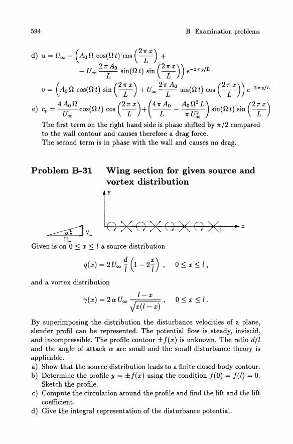
Problem B-31
~Voo u=
Wing section for given source and vortex distribution y
Given is on 0 ~ X ~ I a source distribution
and a vortex distribution
1- X "Y(x)= 2aUoo j ,
x(l-x)
By superimposing the distribution the disturbance velocities of a plane, slender profil can be represented. The potential flow is steady, inviscid, and incompressible. The profile contour ±f(x) is unknown. The ratio d/l and the angle of attack a are small and the small disturbance theory is applicable. a) Show that the source distribution leads to a finite closed body contour. b) Determine the profile y = ±f(x) using the condition f(O) = f(l) = O.
Sketch the profile. c) Compute the circulation around the profile and find the lift and the lift
coefficient. d) Give the integral representation of the disturbance potential.
595
e) Find the disturbance velocities u(x,O+) on the upper and u(x,O-) on the lower side of the wing section. Hint:
Prove that the difference u(x,O+) - u(x, 0-) vanishes at the trailing edge.
Given: a, Ucm I, d, (!
Solution 1
a) J q(x')dx' = 0
o
b) y=±d/l(x-x2 /1)
Y wing section
~ 2 /"/"/"? ~ -? //// /- 1
c) r = - mr U 00 I, F L = mr (! U! 1 , cL = 271"a
1 Jl d ( X') { , 2 2}1/2 , d) cp(x, y) = 271" 2 Uooy 1 - 2 T In (x - x) + y dx + o
1
1 J 1- x' ( y ) , -- 2aUoo J arctan -- dx 271" x'(I-x') x-x'
o
± _ 1 d [ ( X) (X)] 1 - x e) u (x, 0 ) - 1f U 00 1 2 + 1 - 2 Y In 1 _ x ± a U 00 J x (l _ x)
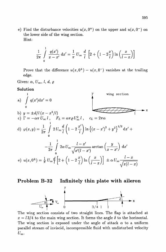
Problem B-32 Infinitely thin plate with aileron
The wing section consists of two straight lines. The flap is attached at x = 13/4 to the main wing section. It forms the angle 8 to the horizontal. The wing section is exposed under the angle of attack a to a uniform parallel stream of inviscid, incompressible fluid with undisturbed velocity Uoo .
596 B Examination problems
a) Determine the coefficients Ao, AI, A2 in the vortex distribution (see F. M. (10.384)-(10.385)) for the given wing section. Use the transformation x = 1/2 (1 + cos <p).
b) Find the lift coefficient CL( a, 8) and the moment coefficient CM( a, 8). c) Determine the center of pressure Xp as function of 8 and a. d) Assume that for 8 = 0 the weight of the aircraft acts at x = 1/4.
Show that the wing for 8/a = 1/2 pitches to the right if the lift equals the weight.
Given: Z, a ~ 1, 8 ~ 1, Uoo
Solution 1 V3 V3
a) Ao = a - -8, Al = --8 , A2 = --8 3 7r 27r
b) cL=27ra-(~7r+V3)8, cM=-ia+8(~+~V3) Xp 1 - 8/a(1/3 + 5/4 V3/7r)
c) -Z = 4 - 8/a(4/3 + 2V3/7r) d) xp/l = 0.176 < 1/4 :::} pitching to the right.
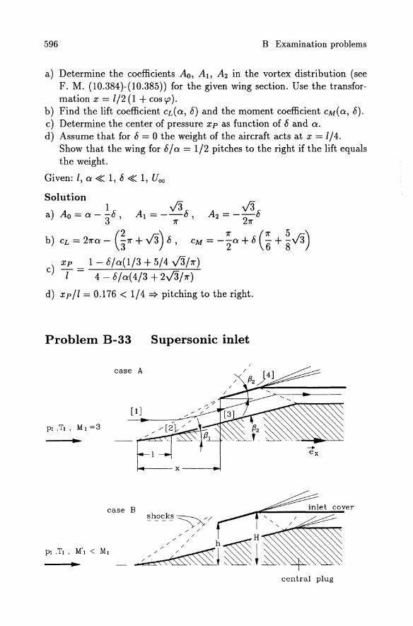
Problem B-33 Supersonic inlet
case A
[1J
...
14--- x ----.!
case B ~h~~.k~~/
/' /
/' / H
~J~i~ ... central plug
597
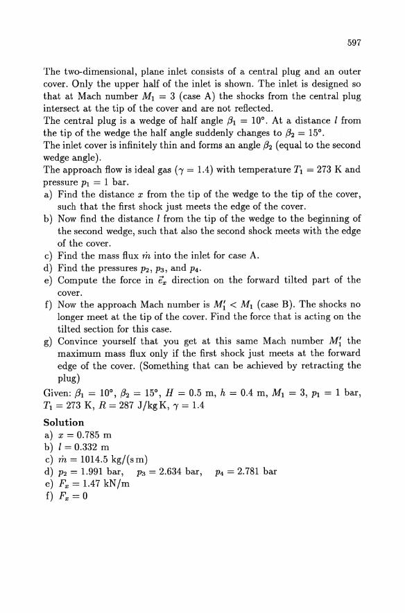
The two-dimensional, plane inlet consists of a central plug and an outer cover. Only the upper half of the inlet is shown. The inlet is designed so that at Mach number Ml = 3 (case A) the shocks from the central plug intersect at the tip of the cover and are not reflected. The central plug is a wedge of half angle (31 = 10°. At a distance I from the tip of the wedge the half angle suddenly changes to (32 = 15°. The inlet cover is infinitely thin and forms an angle (32 (equal to the second wedge angle). The approach flow is ideal gas (-y = 1.4) with temperature Tl = 273 K and pressure PI = 1 bar. a) Find the distance x from the tip of the wedge to the tip of the cover,
such that the first shock just meets the edge of the cover. b) Now find the distance I from the tip of the wedge to the beginning of
the second wedge, such that also the second shock meets with the edge of the cover.
c) Find the mass flux m into the inlet for case A. d) Find the pressures P2, P3, and P4. e) Compute the force in ex direction on the forward tilted part of the
cover. f) Now the approach Mach number is M~ < Ml (case B). The shocks no
longer meet at the tip of the cover. Find the force that is acting on the tilted section for this case.
g) Convince yourself that you get at this same Mach number M~ the maximum mass flux only if the first shock just meets at the forward edge of the cover. (Something that can be achieved by retracting the plug)
Given: (31 = 10°, (32 = 15°, H = 0.5 m, h = 0.4 m, Ml = 3, PI = 1 bar, Tl = 273 K, R = 287 J/kgK, , = 1.4
Solution a) x = 0.785 m b) 1= 0.332 m c) m = 1014.5 kg/(sm) d) P2 = 1.991 bar, P3 = 2.634 bar, P4 = 2.781 bar e) Fx = 1.47 kN/m f) Fx = 0
598
g)
B Examination problems
I
~-----------------------------~
~ ~/
/ / / ,/ / ./ /
- /// ,/ .. - /// . / .
At the position of the plug shown on the left the total inlet cross-section is larger by 2!l.h :::} mlejt > mright.
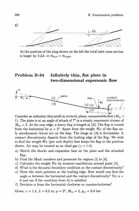
Problem B-34 Infinitely thin, flat plate in two-dimensional supersonic flow
7°
contact discontinuity
--,-..;-~~CP -=1 =
Consider an infinitely thin profil in inviscid, plane, compressible flow (Moo > 1). The plate is at an angle of attack of 7° in a steady, supersonic stream of Moo = 2. At the rear edge, a heavy flap is hinged at [A]. The flap is turned from the horizontal by cp = 2°. Apart from the weight WF of the flap only aerodynamic forces act on the flap. The hinge at [A] is frictionless. A contact discontinuity departs from the trailing edge of the flap. We wish to find the weight WF (per unit depth) that keeps the flap in the position shown. Air may be treated as an ideal gas (-y = 1.4).
a) Sketch the shocks and expansion fans on the plate and the attached flap.
b) Find the Mach numbers and pressures for regions [1] to [4]. c) Calculate the weight WF by moment equilibrium around point [A]. d) What is the dynamic boundary condition on the contact discontinuity? e) Show the wave patterns at the trailing edge. How would you find the
angle a between the horizontal and the contact discontinuity? Try a = o and see if the condition from d) is satisfied.
f) Deviates a from the horizontal clockwise or counterclockwise?
Given: I = 1.4, L = 0.5 m, cp = 2°, Moo = 2, Poo = 0.8 bar
Solution a) Wave pattern
contact discontinuity
--~~--..;j~~-[~ [6]
599
b) MI = 2.26 , M3 = 2.08,
PI = 0.5329 bar, M2 = 1.75 P2 = 1.1884 bar, P3 = 0.7051 bar, M4 = 1.92 , P4 = 0.9155 bar
c) WF = 10.53 N/m
d) P5 = Ps
e) a = 0: P5 = 0.7722 bar, Ps = 0.8213 bar
f) counterclockwise.
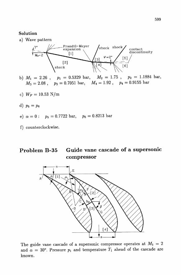
Problem B-35 Guide vane cascade of a supersonic compressor
The guide vane cascade of a supersonic compressor operates at MI = 2 and a = 30°. Pressure PI and temperature TI ahead of the cascade are known.
600 B Examination problems
The leading edge angles of the vane profiles (point [A] and [E]) are zero. The sections EF and BC of the profiles are formed as streamlines of a centered (point [0]) Prandtl-Meyer wave. The sections CD and FG are straight lines parallel to each other. The flow from [1] to [2] is turned by the Prandtl-Meyer waves and compressed. Between positions [2] and [3] is a normal shock and between [3] and [4] the flow is turned into the axial direction. The flow of the ideal gas is isentrop apart from the shock. a) Find the Mach number M2 behind the Prandtl-Meyer wave. Calculate
the angles III and 112 between the first and the second Mach line resp. and the flow direction.
b) Calculate the pressure P2 and the temperature T2 behind the PrandtlMeyer wave. Give the blade spacing h2 •
c) Determine Mach number, pressure, and temperature behind the shock. d) Find the pressure, temperature, and Mach number at the exit of the
cascade (position [4]). Given: Ml = 2, a = 30°, (3 = 52.822°, Pl = 2 bar, Tl = 250 K, R = 287 J/kgK, 'Y = 1.4, s = 0.15 m
Solution a) M2 = 1.2, III = 30°, 112 = 56.44° b) P2 = 6.435 bar, T2 = 349 K, h2 = 4.58 cm c) P3 = 9.7655 bar, T3 = 394 K, M3 = 0.842 d) P4 = 15.17 bar, T4 = 447 K, M4 = 0.18
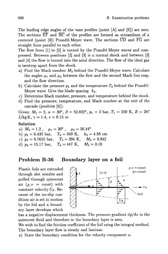
Problem B-36 Boundary layer on a foil
Plastic foils are extruded through slot nozzles and pulled through quiescent air (e, v = const) with constant velocity UFo Because of the no-slip condition air is set in motion by the foil and a boundary layer develops which
u=o p,V =const
p=const
-UF
foil
has a negative displacement thickness. The pressure gradient dp/dx in the quiescent fluid and therefore in the boundary layer is zero. We wish to find the friction coefficient of the foil using the integral method. The boundary layer flow is steady and laminar. a) State the boundary condition for the velocity component u.
601
b) For the velocity distribution in the boundary layer
;F = a + b ~ + C (~r find the constant a, b, and C from boundary conditions and from the assumption, that the shear stress vanishes at the edge of the boundary layer (8 is the boundary layer thickness). The momentum thickness 82
is introduced as 6
82 U; = J (U - u) u dy .
o
c) Show that with 82 the momentum equation can be brought to the form
d82 Tw
dx
d) For the given velocity distribution find the ratio 82/8. e) Give the relationship between wall shear stress Tw and the momentum
thickness 82 •
f) Find the ordinary differential equation for 8~ from the equation given in part c). Solve the equation subject to 82(x=0)=0.
g) Determine the coefficient of friction
C JUFX = Tw JUFX j v fl U'fr /2 v
and compare with the exact result ( Cj JUF x/v = 0.8875).
Given: fl, v, U F
Solution a) u(x=O, y) = 0, u(x, y=O) = UF, u(x, y=8) = U = 0
b)a=l, b=-2, c=l
d) 82/8 = -1/5
2 "lUF e) Tw = sT
f) ~ ~(82) = ~. ~ 8 = J~ VX 2 dx 2 5 U F' 2 5 U F
g) Cj JU:x = If = 0.8944
The power of CFD
The book provides an elementary tutorial pre en
tation on computational Ruid dynamics (CFD). emphasizing the fundamental and urveying a variety of olution techniques whose application range from low peed incompressible Row to hypersonic Row. It is aimed at per ons who have little or no experience in thi field. both recent graduates as well a professional engineers. and will provide an insight to the phi losophy and power of CFD. an under tanding of the mathematical nature of the fluid dynamics equation. and a famil iarity with various solution technique. For the econd edition the text ha been revi ed and updated. and Chapter 9 has been completely rewritten.
., ... the book is highly recommended a an introduction for engineer. phy ici ts and applied mathematician to CFD."
Spnngtr·\'C'rl.tg. P. O. Box 11 IJ ",0. 0 ,106.41 ~rhn. G~rrn.1ny,
J.F. Wendt (Ed.)
Computational Fluid Dynamics An Introduction
2nd. ed. t996. XII, 301 pages. Hardcover OM 148.-ISBN 3-540-59471-X
"'kr ~~llo , ..... w~lhov. DUlIU. In U.l ,wnlt"..lN Iau1 \'At tI~II\.II"".
Please order by Fax: +49 - 30 · 827 - 87 - 101 e-mail: [email protected] or through your bookseller
• •••••••••
Springer
Common roots I.H. Feniger, M. Peri,
Computational Methods for Fluid Dynamics 1!}!}6. XIV, 356 pages. !}5 ligures. Soflcove r D M 74,-ISBN 3'540'59434'5
Price iubJ~1 t.o Ch,llIlgC' Wltl'ioul no\ict'. In E..U countrit1o Ih.t' lonl VAT i:!li ~ffKti'''f'.
PI@ase order by Fax: +49 . 30 ·827 87 - 301 e· rnai I: arde rs@ls:pringer.de or Ihrou 9 h you r boo kselle r
.~ The book offers an over-view of the techniques used to solve problems in Auid mechanics on computers and describes in detail those most often used in practice. Included are advanced technique in computational fluid dynamics, like direct and large-eddy simulation of turbulence, multigrid methods, parallel
computing, moving grids, structured. block-structured and unstructured boundary-Ii ned grids, free surface flows. The book shows common roots and basic principles for many apparently different methods. The book also contains a great deal of practical advice for code developers and users, it is designed to be equally useful to beginners and experts.
• •••••••••
Springer
Springer and the
environ meat 4tSpringer we firmly believe that an
illtetnational science publisher has a
sp~ial obligation to the environment,
~iJ1d:J)Ur corporate policies consistently
reflect this conviction.
We also expect our business partners -
paper mills, printers, packaging
manufacturers, etc. - to commit
themselves to using materials and
production processes that do not harm
the environment. The paper in this
book is made from low- or no-chlorine
pulp and is acid free, in conformance
with international standards for paper
permanency.
Springer