Embed Size (px)
Citation preview
A sun® • microsystems
·~J~ ~ . ~ - \ . .
16 Channel Asynchronous Line Multiplexer-2
Field Service Manual · and Installation Notes
Part No: 813-1029-05 Revision: A of December 7, 1987
L~:
~~SUD® ~" ' · ~ microsystems
16 Channel Asynchronous Line Multiplexer-2
Field Service Manual and Installation Notes

Credits and Trademarks
Multibus is a trademark of Intel Corporation.
VMEbus is a trademark of Motorola, Inc. :!;>
Sun Microsystems and Sun Workstation are registered trademarks of Sun Microsystems, Incorporated. Sun-2, Sun2 Sun-2/xxx, Sun-3, Sun3, Sun-3/xxx, Deskside, SunStation, Sun Core, Sun Windows, and DVMA are trademarks of Sun Microsystems, Incorporated.
UNIX is a trademark of AT&T Bell Laboratories.
This equipment generates, uses, and can radiate radio frequency energy and if not installed and used in accordance with the instructions manual, may cause interference to radio communications. It has been tested and found to comply with the limits for a Class A computing device pursuant to Subpart J of Part 15 of FCC Rules, which are designed to provide reasonable protection against such interference when (~') operated in a commercial environment. Operation of this equipment in a residential area is likely to cause interference in which case the user at his own expense will be required to take whatever measures may be required to correct the interference.
Copyright © 1987 by Sun Microsystems, Inc.
This publication is protected by Federal Copyright Law, with all rights reseived. No part of this publication may be reproduced, stored in a retrieval system, translated, transcribed, or transmitted, in any form, or by any means manual, electric, electronic, electro-magnetic, mechanical, chemical, optical, or otherwise, without prior explicit written permission from Sun Microsystems.
-ii-
(~

u
u
Contents
Chapter 1 Inspection and Unpacking ........................................................................ 3 1.1. Inspection............................................................................................................................. 3
1.2. Unpacking............................................................................................................................ 3
Chapter 2 General Description and Cautions ...................................................... 7 2.1. General Description ...................................................................................................... .
Test Equipment ............................................................................................................. .
2.2. Important Cautions during Installation .............................................................. .
Power Off Caution ...................................................................................................... .
Electrostatic Discharge Caution .......................................................................... .
Springfinger Caution .................................................................................................. .
7
7
8
8
8
8
Chapter 3 Board Location and Installation Instructions ............................. 13 3.1. Tools Required .................................................................................................................. 13 3.2. Board Location and Addressing .............................................................................. 13
3.3. Board Installation ............................................................................................................ 13
Graceful Power-Down ·······································································.·~~H~~'.'............... 13
3.4. s=~::~~-~:~;:~~~·:::::::::::::::::::::::::::::::::::::::;:;:;~~~~!~l~~~i~l:~;!!'.:.... ~: Board Removal (if necessary) ······························.·~·~~J.::.~,~·:m'L:.~ ... ~U~~;~t>».: .. :.:.:.:.;,l:.; ... ::::;;;::Y L?. Installation of Additional Controller Board(~)J'.t:~····~@E~;~~~t ..... J~~U,~,~~U;~: .. :'.>t:: 1:6\
3.5. Operating System Configuration .............................. :dlE .. ~~~.E~.~ .. ~ . .i.C~Ib,,_::dC:.; :}/f6
19
-iii-

Contents-Continued
Chapter 5 Device Connector Assembly - Wall or Floor (j
Mounting ................................................................................................................. . 23
Chapter 6 Connecting External Devices to the ALM-2 ................................ . 27
Chapter 7 RS-232 Loopback Diagnostics ................................................................ . 33 7.1. Tools Required ................................................................................................................. . 33
7 .2. RS-232 Loopback Connectors ................................................................................ . 33
7.3. The RS-232 Loopback Program ............................................................................ . 33
Software Requirements ............................................................................................ . 34
Running the RS-232 Loopback Program ....................................................... . 34
Loopback Status Messages ..................................................................................... . 34
Test Completion ...................................................... ~ .................................................... . 35
Chapter 8 Printer Port Loopback Diagnostics ................................................... . 39 8.1. Tools Required ................................................................................................................. . 39
8.2. Printer Port Loopback Connectors ........................................................................ . 39
8.3. The Printer Port Loopback Program .................................................................... .
Software Requirements ............................................................................................ . 39n 39
Running the Printer Port Loopback Program .............................................. . 39
Test Completion ........................................................................................................... . 40
Appendix A Support Aids .................................................................................................. . 43 A.1. Software System Configuration Aids ................................................................. . 43
/dev File System Modifications ........................................................................... . 43
Results of the Previous Step .................................................................................. . 44
-iv-

l_)
Figures
Figure 1-1 Unpacking tl1e ALM-2 ........................................................................................... 4
Figure 3-1 Backplane Jumper Locations ........................................................................... 15
Figure 4-1 OCA Assembly - Rack Mount .......................................................................... 19
Figure 4-2 OCA Installation - Rack Mount ....................................................................... 20
Figure 5-1 OCA Assembly - Floor or Wall Mount ....................................................... 23
u Figure 6-1 Connecting External Devices to the ALM-2 ............................................. 27
-v-

i.:w! '·. I
i

{ ~)
Tables
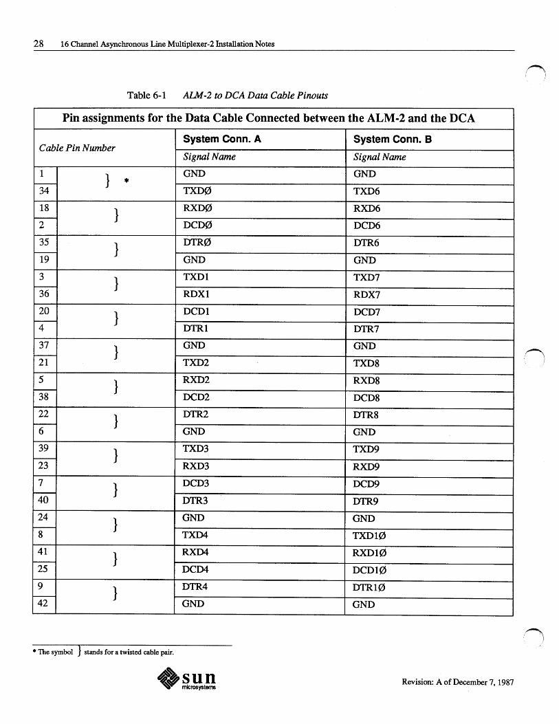
Table 6-1 ALM-2 to DCA Data Cable Pinouts ............................................................. 28
Table 6-2 ALM-2 to DCA Data Cable Pinouts Continued... .............................. 29
Table 6-3 Printer Port Pinouts ................................................................................................. 30
Table A-1 Field Replaceable Units for the ALM-2 .................................................... 43
-vii-

n
(j l

/ I
\_,,I
u
~)
Purpose
Other Documentation You Will Need
Pref ace
This manual contains infonnation about the installation and use of the 16 Channel Asynchronous Line Multiplexer-2. It also contains an Appendix containing data intended for Sun Customer Service Engineers.
o Card Cage Slot Assignments and Backplane Configuration Procedures Sun PIN 813-2004-XX
o Card Cage Slot Assignments and Backplane Configuration Procedures for the 16 Channel Asynchronous Line Multiplexer-2
D
D
D
D
D
Sun PIN 813-2045-XX
16 Channel Asynchronous Line Multiplexer-2 Configuration Procedures Sun PIN 813-2042-XX
Installation Manual Addendum for the Sun-3/180 Rackmounted System Sun PIN 800-1362-XX
Installing UNIX on the Sun Workstation Sun PIN 800-1158-XX
System Administration for the Sun Workstation Sun PIN 800-1323-XX
Sun System Diagnostics Manual Sun PIN 800-2111-XX
-ix-

:f} I)
:fj
r'T) ]'

( \_.,,;!
u
1 Inspection and Unpacking
Inspection and Unpacking..................................................................................................... 3
1.1. Ins:Pection ............................................................................................................................. 3
1.2. Unpacking ............................................................................................................................ 3

;n )
n /

/ .
~;
/ \
\~
1.1. Inspection
1.2. Unpacking
1 Inspection and Unpacking
When you receive your shipment, inspect all shipping cartons immediately for any evidence of damage. If any carton is severely damaged, request that the carrier's agent be present when the carton is opened. If the carrier's agent is not present when a carton is opened and the contents are found to be damaged, keep all contents and packing materials for the agent's inspection.
The Figure on the following page shows the Packing Box in its most complex and complete configuration. You would receive this box if you ordered the ALM-
2 as a separate addition to your Sun Logic Enclosure. If you already have an ALM-2 (or other related equipment), you may receive an abbreviated version of this Packing Box.
Save the packing materials for future use.
3 Revision: A of December 7, 1987

4 16 Channel Asynchronous Line Multiplexer-2 Installation Notes
Figure 1-1 Unpacking theALM-2
Installation Manual
Beg with Hardware -----~r.
ALM -2 Board
~~r--.:....Foam
~:;.-r~:'.l!~~f--!.-T~e
I~ i
DCA
1 . 75 inch Filler Panel
,() /
Revision: A of December 7, 1987

( i
\__/
./
( \_,)
( \
\_____.,,)
2 General Description and Cautions
General Description and Cautions ................................................................................... 7
2.1. General Description ....................................................................................................... 7
Test Equipment .............................................................................................................. 7
2.2. Important Cautions during Installation ............................................................... 8
Power Off Caution ...................................................................................................... .
Electrostatic Discharge Caution .......................................................................... .
Springfinger Caution .................................................................................................. .
8
8
8

(~ I

2.1. General Description
Test Equipment
2 General Description and Cautions
The 16 Channel Asynchronous Line Multiplexer-2 (ALM-2) is a serial communications subsystem assembly. It provides an interface between the VME bus and the sixteen RS-232-C serial ports and the single (Centronics compatible) parallel printer port.
The ALM-2 consists of a Controller board, a Device Connector Assembly (DCA), and two Data cables to connect the Controller board to the DCA.
o The ALM-2 Controller board provides the interface between the VME bus and the DCA. The Controller board also has a Centronics compatible parallel printer port.
o The rack or wall mountable DCA has sixteen RS-232-C/RS-423 ports for connection to customer equipment, and two Data ports for connection to the Controller board.
o The two Data cables are 2.4 meters in length, and connect the Controller board to the DCA (a cable is not provided for the printer port).
The ALM-2 is a slave-only VME device, and uses Direct Memory Access from its on-board RAM to communicate with the serial ports. It uses full-duplex signalling, and has a maximum data transfer rate of 19200 baud (forRS-232) or 38400 baud (forRS-423) on all 16 serial channels. Asynchronous devices using the RS-232-C standard signal levels can be connected to the ALM-2 assembly. Sun software can configure each channel separately to work with serial devices at any of the following baud rates:
50, 75, 110, 134.5, 150, 300, 600, 1200, 1800, 2400, 4800, 9600, 19200 and 38400.
Loopback Connectors are provided for the RS-232 ports, and a special Loopback Connector is provided for the Printer port.
7 Revision: A of December 7, 1987

8 16 Channel Asynchronous Line Multiplexer-2 Installation Notes
2.2. Important Cautions during Installation
Power Off Caution
Electrostatic Discharge Caution
Springfinger Caution
Turn off the power and disconnect the power cord from the Logic Enclosure before inserting or removing any boards.
Electrostatic Discharge Caution - Some of the devices on Sun boards are very sensitive to electrostatic discharge (they can be permanently damaged). An electrostatic charge can build up in the human body and then discharge when you touch the board. Before handling any board, make sure that you have placed your hand on a conductive surface that is grounded to a common earth ground, (such as the metal screws on an AC receptacle cover) to discharge the static electricity present in your body.
Springfinger Caution - Springfingers are metal strips that are installed between the edge of the PC board and the outer panel to reduce RPI emissions. Serrated metal ''fingers'' protrude from either side of the strip.
If a board WITH springfingers is installed next to a board WITHOUT springfingers, the insulator shield on the outside of the fingers MUST be present to prevent possible shorting of component leads to the springfingers.
Installation of a board WITHOUT springfingers may affect RPI emissions and may therefore affect FCC compliance. Sun will no longer be responsible for FCC compliance if non-springfingered boards are added to a system originally shipped WITH springfingers and FCC approval.
If a logic enclosure contains boards WITH and WITHOUT springfingers, use the following guidelines:
o Before removing a board WITHOUT springfingers, remove the board below it (or to the left of it for pedestal mode) ifthat board is equipped WITH springfingers and an outer insulator shield.
o Replace any filler panel equipped WITH springfingers by pulling out the air restrictor panel far enough to allow the springfingers to lay against the filler panel. Push both units into place simultaneously, and secure with the appropriate fasteners. This procedure makes replacement of the filler panels easier, and reduces the possibility of damage to the springfingers.
o Always install a board WITHOUT springfingers first, and then replace the board WITH springfingers and insulator shield in the slot below it (or to the left).
If a board WITH springfingers is installed next to a board or filler panel also equipped WITH springfingers, the outside insulator shields should be removed.
Ensure that the insulator strip between the inner side of the springfingers and the
:~ !
PC board is intact· at all times. .~ I \
~~sun ~~ microsystems Revision: A of December 7, 1987

Chapter 2 - General Description and Cautions 9
When removing and replacing boards with springfingers, check the condition of the insulator strip/shield(s) and replace if damaged.
Call 800 USA-4SUN with any questions, or for information on how to obtain additional insulator strips or shields.
Revision: A of December 7, 1987

3 Board Location and Installation Instructions
Board Location and Installation Instructions .......................................................... 13
3.1. Tools Required.................................................................................................................. 13
3.2. Board Location and Addressing.............................................................................. 13
3.3. Board mstallation ............................................................................................................ 13
Graceful Power-Down .............................................................................................. 13
Installation ........................................................................................................................ 13
3.4. System Hardware Configuration ............................................................................. 15
Board Removal (if necessary) ............................................................................... 16
Installation of Additional Controller Board(s) ............................................. 16
3.5. Operating System Configuration ............................................................................ 16

~)
()

/ \_,i
u
3.1. Tools Required
3.2. Board Location and Addressing
3.3. Board Installation
Graceful Power-Down
Installation
3 Board Location and Installation
Instructions
The following tools will be needed to install the ALM-2 Controller Board:
o Set of Metric hexagonal (Allen) wrenches, including 2.5mm.
o Phillips screwdrivers #1 and #2.
o Standard blade screwdriver.
Refer to the Card Cage Slot Assignments and Backplane Con.figuration Procedures for the 16 Channel Asynchronous Line Multiplexer-2 for information and cautions about Logic Enclosure backplane jumpering and location of the ALM-2
Controller Board in your particular Sun system.
If the system is running and you want to power-down, ensure that the system administrator has performed the following steps.
1. W amed clients or other workstation users to log out.
2. As super-user, entered a command such as:
/etc/halt or /etc/fasthalt
The program called by this command ensures that all data in the buffers is written to the disk before UNIX is halted.
When UNIX is halted, you may tum the system power off.
1. Power-down the Sun Logic Enclosure, and unplug the AC Line cord.
2. Remove the anti-static bag from the Controller board.
3. Refer to the 16 Channel Asynchronous Line Multiplexer-2 Configuration Procedures, and verify that the jumper and switch settings are set to the correct positions for your application.
13 Revision: A of December 7, 1987

14 16 Channel Asynchronous Line Multiplexer-2 Installation Notes
4. Using the Card Cage Slot Assignments and Backplane Configuration Procedures for the 16 Channel Asynchronous Line Multiplexer-2, choose the target slot in the Logic Enclosure card cage. Using the 2.5mm hexagonal wrench, remove the filler panel on the rear of the card cage corresponding to the target slot (save the screws). For Sun-3 models, remove the air restrictor also.
5. Insert the ALM-2 Controller Board into the the cardcage so that the component side faces towards the right (when viewed from the rear). The board should slide into the cardcage slot with little resistance and fit snugly when seated into the backplane connectors. While a moderate amount of force is required to seat the board, anything in excess of this is cause for inspection. Check the cardcage slot for any obvious obstructions, and both the board and the backplane for damage (bent connector pins, etc.).
6. Using the hex head screws from step 4, secure the board to the card cage.
Revision: A of December 7, 1987
!~ ! J

3.4. System Hardware Configuration
Chapter 3 - Board Location and Installation Instructions 15
1. Power-down the system, and unplug the AC Line cord.
2. Gain access to the solder side of the cardcage backplane in order to check the backplane jumpers (Correct location of the system backplane jumpers is described in the Card Cage Slot Assignments and Backplane Configuration Procedures for the 16 Channel Asynchronous Line Multiplexer-2) .
• • If you have a pedestal-type system, unsnap the front bezel and unfasten the four screws holding the hinged power supply panel in place. Insert a large, flat-blade screwdriver in the openings between the panel and the sides of the pedestal to release the panel from the pedestal. Gently lower the power supply tray.
• If the system is rackmounted, unsnap the bezel and remove the 12 screws that secure the RFI shield. Ensure that all backplane jumpers are configured as indicated in the Cardcage Slot Assignments and Backplane Configuration Procedures and the special Cardcage Slot Assignments and Backplane Configuration Procedures for the 16 Channel Asynchronous Line Multiplexer-2. Figure 3-1 illustrates the backplane jumpers.
Figure 3-1 Backplane Jumper Locations
r---,
Pl
L---
0 : PXOO
® (!)
: PXOl
® 0
: PX02
® (!)
: PX03
~
~PX04 ~
Slot X (any slot in the Sun cardcage) As viewed from the front of the system
3. Close up the host system Logic Enclosure.
Revision: A of December 7, 1987
16 16 Channel Asynchronous Line Multiplexer-2 Installation Notes
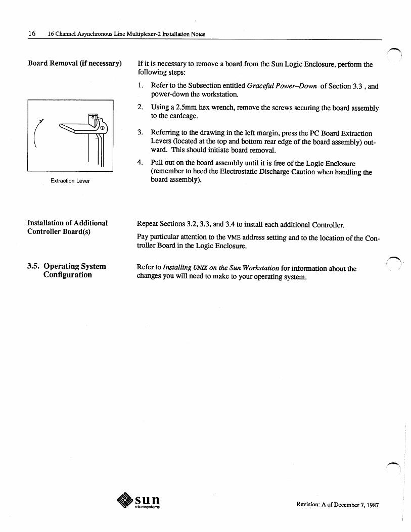
Board Removal (if necessary)
( Extraction Lever
Installation of Additional Controller Board(s)
3.5. Operating System Configuration
If it is necessary to remove a board from the Sun Logic Enclosure, perform the following steps:
1. Refer to the Subsection entitled Graceful Power-Down of Section 3.3 , and power-down the workstation.
2. Using a 2.5mm hex wrench, remove the screws securing the board assembly to the cardcage.
3. Referring to the drawing in the left margin, press the PC Board Extraction Levers (located at the top and bottom rear edge of the board assembly) outward. This should initiate board removal.
4. Pull out on the board assembly until it is free of the Logic Enclosure (remember to heed the Electrostatic Discharge Caution when handling the board assembly).
Repeat Sections 3.2, 3.3, and 3.4 to install each additional Controller.
Pay particular attention to the VME address setting and to the location of the Controller Board in the Logic Enclosure.
Refer to Installing UNIX on the Sun Workstation for information about the changes you will need to make to your operating system.
Revision: A of December 7, 1987
\.._)
Device Connector Assembly - Rack Installation
4
Device Connector Assembly - Rack Installation ............................................. 19

()
I~ I

u 4
Device Connector Assembly - Rack Installation
If you are going to install the Device Connector Assembly (DCA) into a Sun Rack, perfonn the following instructions.
1. Using four 8mm M3 screws, attach the long brackets to the DCA as shown in Figure 4-1.
2. Remove the highest available filler panel from the rear of the rack (see Figure 4-2).
NOTE The DCA is 5 114 inches high, and a large percentage of Sun-3 Racks have 7 inch filler panels; therefore, a 1 314 inch filler panel (with 2 mounting screws) is shipped with the ALM-2 to cover this extra space. If you have one of the newest Sun Racks, it will have 5 114 inch filler panels, and you may discard the 1 314 inch filler panel.
NOTE If there is no space in the rear of the Rack for the DCA (for example, if there are already three ALM-ls installed), see Chapter 5 - Device Connector Assembly -Wall or Floor Mounting/or alternative mounting instructions.
Figure 4-1 DCA Assembly - Rack Mount
__ .....
19 Revision: A of December 7, 1987

20 16 Channel Asynchronous Line Multiplexer-2 Installation Notes
3. Using four 10-32 oval head screws, secure the DCA to the rack in the space made available by removing the filler panel in Step 2.
Figure 4-2 DCA Installation - Rack Mount
Cable Management
Bar
Fear RETMA Ra.I
Feusable Tie Wra
NOTE The Data cables referred to in Steps 4 and 5 must be routed down the LEFT side of the Rack (when viewed from the rear). Figure 4-2 shows the correct cable routing.
4. Connect a 50-Pin Data cable from the connector labelled SYSTEM CONN A on the DCA to the connector labelled SYSTEM CONN A on the Controller Board.
5. Connect a 50-Pin Data cable from the connector labelled SYSTEM CONN B on the DCA to the connector labelled SYSTEM CONN B on the Controller Board.
6. Repeat Steps 1 through 5 for each additional DCA.
Revision: A of December 7, 1987
,!)
(\ ' /

u
~I
5 Device Connector Assembly - Wall or Floor Mounting
Device Connector Assembly-Wall or Floor Mounting ............................ 23


u
5 Device Connector Assembly - Wall or
Floor Mounting
If it is not applicable or possible to mount the DCA into a Rack (a Pedestal or DeskTop installation, or if the rear of the Rack is full), then it may be installed onto the wall or floor. To mount the DCA to the wall or floor, perform the following steps.
1. Using the four 8mm M3 screws provided, attach the short brackets to the Device Connector Assembly (DCA) as shown in Figure 5-1.
2. Using mounting screws appropriate for your application, secure the DCA to the wall or floor by inserting your mounting screws through the four slots in the mounting bracket and into the wall or floor.
CAUTION Before installing the DCA, select a location that will provide physical safety for the DCA, the cables and, above all, any personnel working in the area.
Figure 5-1 DCA Assembly - Floor or Wall Mount
•
+~.!! 23 Revision: A of December 7, 1987

24 16 Channel Asynchronous Line Multiplexer-2 Installation Notes
3. Connect a 50-Pin Data cable from the connector labelled SYSTEM CONN A on the DCA to the connector labelled SYSTEM CONN A on the Controller Board.
4. Connect a 50-Pin Data cable from the connector labelled SYSTEM CONN B on the DCA to the connector labelled SYSTEM CONN B on the Controller Board.
5. Repeat Steps 1 through 4 for each additional DCA.
Revision: A of December 7, 1987.
(~ !, i
It]
/
( ·~
I
\ .. _)
Connecting External Devices to the ALM-2
6
Connecting External Devices to the ALM-2 .............................................................. 27

~ !
/~ I
Ir;

u
Figure 6-1
{ I
i I
~
6 Connecting External Devices to the
ALM-2
The ALM-2 ports are configured as Data Terminal Equipment (DTE) ports (as are most ASCII terminals). These ports are designed to communicate with other Data Terminal Equipment as well as Data Communication Equipment (DCE) using RS-232 signalling conventions. Figure 6-1 shows examples of how the ALM-2's DCA ports connect to various types of DTE and DCE devices. Tables 6-1, 6-2 and 6-3 show the connector pinouts for cables that connect directly to the ALM-2.
Connecting External Devices to the ALM-2
The simplest cable for connectinq a terminal to the ALM-2 would be wired like this:
ALM-2 Termnal
(DTE) (DTE)
TXD 2 3
RXD 3 2
GAD 7 7
If a terminal or printer requires additional siqnals to operate, such as DCD or DTR, the cable connections would look like this:
ALM-2 Termnal
(DTE) (DTE)
TXD 2 3
RXD 3 2
GAD 7 7
OCD 8 20
DTR 20 8
A cable for a modem would be wired like this:
ALM-2 Modem
(DTE) (DCE)
TXD 2 2
RXD 3 3
GAD 7 7
OCD 8 8
DTR 20 20
27 Revision: A of December 7, 1987
28 16 Channel Asynchronous Line Multiplexer-2 Installation Notes
Table 6-1 AIM-2 to DCA Data Cable Pinouts
Pin assignments for the Data Cable Connected between the ALM-2 and the DCA
Cable Pin Number System Conn. A System Conn. B
Signal Name Signal Name
1 } GND GND - * 34 TXD0 TXD6
18 } RXD0 RXD6 -2 DCD0 DCD6
35 } DTR0 DTR6 -
19 GND GND
3 } TXDl TXD7 -36 RDXl RDX7
20 } DCDl DCD7 -4 DTRl DTR7
37 } GND GND ,___
21 TXD2 TXD8 (~
5 } RXD2 RXD8 -38 DCD2 DCD8
22 } DTR2 DTR8 -6 GND GND
39 } TXD3 TXD9 -23 RXD3 RXD9
7 } DCD3 DCD9 -40 DTR3 DTR9
24 } GND GND
-8 TXD4 TXD10
41 } RXD4 RXD10 -25 DCD4 DCD10
9 } DTR4 DTR10 -42 GND GND
• The symbol } stands for a twisted cable pair.
Revision: A of December 7, 1987

Chapter 6 - Connecting External Devices to the ALM-2 29
Table 6-2 AIM-2 to DCA Data Cable Pinouts Continued ...
Pin assignments for the Data Cable Connected between the ALM-2 and the DCA
Cable Pin Number System Conn. A System Conn. B
Signal Name Signal Name
26 } TXD5 TXDll - * 10 RXD5 RXDll
43 } DCD5 DCDll -27 DTR5 DTRll
11 } RTS0 GND
-44 CTS0 TXD12
28 } DSR0 RXD12 -
12 TXC0 DCD12
45 } RXC0 DTR12 -29 RTSl GND
u 13 } CTSl TXD13 -46 DSRl RXD13
30 } TX Cl DCD13 -14 RX Cl DTR13
47 } RTS2 GND -31 CTS2 TXD14
15 } DSR2 RXD14 -48 TXC2 DCD14
32 } RXC2 DTR14 -
16 RTS3 GND
49 } CTS3 TXD15 -
33 DSR3 RXD15
17 } TXC3 DCD15 ......_
50 RXC3 DTR15
u * The symbol } stands for a twisted cable pair.
Revision: A of December 7, 1987

30 16 Channel Asynchronous Line Multiplexer-2 Installation Notes
Table 6-3 Printer Port Pinouts
Pin Assignments for the Parallel Printer Port (DB25 Connector)
Pin Number Signal Name
1 STRB
2 DATABIT0
3 DATA BIT 1
4 DATABIT2
5 DATABIT3
6 DATABIT4
7 DATABIT5
8 DATABIT6
9 DATABIT7
10 ACK
12 PE
13 SLCT
18 thru 24 GND
()
Revision: A of December 7, 1987
7 RS-232 Loopback Diagnostics
RS-232 I..oopback Diagnostics.............................................................................................. 33
7.1. Tools Required.................................................................................................................. 33
7.2. RS-232 Loopback Connectors ................................................................................. 33
7.3. The RS-232 Loopback Program ............................................................................. 33
Software Requirements ............................................................................................. 34
Running the RS-232 Loopback Program ........................................................ 34
Loopback Status Messages ...................................................................................... 34 / " \_,;
1 Test Completion ............................................................................................................ 35
u

0i ' /
u
\ \ ·~
u
7 .1. Tools Required
7.2. RS-232 Loopback Connectors
7 RS-232 Loopback Diagnostics
o ALM-2 RS-232 Loopback Connectors (ALM-1 loopback connectors will not work.).
The RS-232 Loopback Connector is a 25-Pin Sub-D connector that has its outputs wired back to its inputs. Therefore, the data that is written to the serial port is immediately read back (and should be exactly the same).
NOTE The ALM-2 RS-232 Loopback Connector and the Printer Port Loopback Connector look very similar. The RS-232 Loopback Connector can be recognized by the fact that it has only three wires connected to six pins. The Printer Port Loopback Connector has ten wires connected to twenty pins.
An RS-232 Loopback Connector is wired as follows:
o Pin 2 is connected to Pin 3
o Pin 4 is connected to Pin 5
o Pin 8 is connected to Pin 20
7 .3. The RS-232 Loop back Program
Used in conjunction with the RS-232 Loopback Connectors, this Loopback Program compares the data being written to the serial ports with the data being read back from them. If the data does not match or is not present, the test will stop and an error message will be reported.
The program sets the input mode to RAW (unprocessed), and sends the the numbers 0 through 255 (in a binary code) to the serial port(s). The program will write to all the serial ports, or it will write to individual ports as specified by the user.
33 Revision: A of December 7, 1987

34 16 Channel Asynchronous Line Multiplexer-2 Installation Notes
Software Requirements
Running the RS-232 Loopback Program
NOTE In the following descriptions and procedures the # is shown before commands you are to enter. This symbol represents the 'single user' system prompt. Do not enter this symbol as a part of the command.
The RS-232 Loopback Program runs under control of the UNIX operating system. To avoid conflicts with UNIX system login or shell processing, the file I etc It t y s should be copied. To copy the file, enter the command
# cp /etc/ttys /etc/ttys-
N ow that the original file has been copied, edit I etc It t y s and change the file status for each port you wish to test to 0. For example: 12ttyh0 should be changed to 02ttyh0. If this step is not performed, UNIX will 'steal' characters when it attempts to process commands, and the test will fail.
After you have finished editing I etc/ttys, you need to notify 'init' that the new I etc It t y s file is ready for the loopback test. Enter the command: # kill -1 1
To run the RS-232 Loopback Program you need to do two things. First, insert the RS-232 Loopback connector into the DCA port(s) to be tested. Second, enter the command loopback followed by the name of the port (device) that you wish to test. For example, to test port 0 of the ALM-2, you would enter the line: # loopback /dev/ttyhO
NOTE Be sure that you enter the port name exactly as it appears in the directory I dev
If no ports are named after the loopback command, you will be asked to name one.
Loopback Status Messages The RS-232 Loopback Program can generate four types of status messages. Three of the messages indicate errors; the fourth type of message indicates that the program has run successfully.
For example, if the test on port zero is successful, the message /dev/ttyhO tested OK will be displayed.
The three error messages are:
[port] does not exist [port] does not respond [port] data does not match
/~ l I
~l I
The does not exist error message will occur ifthe program cannot find (r) the port. The following are some probable causes of this condition.
Revision: A of December 7, 1987

u
( \) Test Completion ~
u
Chapter 7 - RS-232 Loopback Diagnostics 35
o The specified port is not found in the I de v directory.
o The major device number of the I dev directory is incorrect.
o The ALM-2 is not configured in the kernel.
The does not respond error message will occur if data was sent to the port but no data returned. The following are some probable causes of this condition.
o The port on the DCA may be broken.
o The RS-232 loopback connector may be missing or broken.
o The Data cable between the ALM-2 and the DCA may be poorly connected or broken.
The data does not mat ch error message will occur if the data read back from the port does not match the data written to it (the command Xor will list the bits that are different). The following are some probable causes of this condition.
o A 'noisy' Data cable.
o A framing error.
o The I etc/ttys file status is incorrect.
After completing the Loopback test(s), it is very important that you restore the /etc/ttys file to its original content. To do this, simply enterthe command # mv /etc/ttys- /etc/ttys
Once the I etc It t y s file is restored to its original state, you need to notify 'init' that this has been done. Enter the command: # kill -1 1
Remove any RS-232 Loopback Connectors from the DCA.
The RS-232 Loopback test is now complete.
+~.!! Revision: A of December 7, 1987

() /

u 8
Printer Port Loopback Diagnostics
Printer Port Loopback Diagnostics................................................................................. 39
8.1. Tools Required.................................................................................................................. 39
8.2. Printer Port Loopback Connectors ......................................................................... 39
8.3. The Printer Port Loopback Program ..................................................................... 39
Software Requirements ............................................................................................. 39
Running the Printer Port Loopback Program ............................................... 39
Test Completion ............................................................................................................ 40
u


Li
( ~i ~I
u
8.1. Tools Required
8.2. Printer Port Loop back Connectors
NOTE
8.3. The Printer Port Loopback Program
Software Requirements
Running the Printer Port Loopback Program
8 Printer Port Loopback Diagnostics
o ALM-2 Printer Port Loopback Connector (ALM-1 connectors will not work).
The Printer Port Loopback Connector is a 25-Pin Sub-D connector that has its output routed back to its input. Therefore, the data that is written to the printer port is immediately read back (and should be exactly the same).
The ALM-2 Printer Port Loopback Connector and the RS-232 Loopback Connector look very similar. The Printer Port Loopback Connector can be recognized by the fact that it has ten wires connected to twenty pins. The RS-232 Loopback Connector has only three wires connected to six pins.
Used in conjunction with the Printer Port Loopback Connector, the Printer Port Loopback Program compares the data being written to the printer port with the data being read back from it. If the data does not match or is not present, the test will stop and an error message will be reported.
The only software requirement is that you be running Sun software release 3.5 or later. With the 3.5 software release you will have received a manual entitled Sun System Diagnostics Manual (Sun PIN 800-2111-XX). This manual describes in great detail how to run the system diagnostics, and the ALM-2 prin~r port loopback program is a part of these system diagnostics.
To run the Printer Port Loopback Program perform the following steps.
1. Read the Sun System Diagnostics Manual carefully.
2. Insert the Printer Port Loopback connector into the printer port on the ALM-
2 's back panel.
3. After having read the Sun System Diagnostics Manual, select the Options menu from the System Diagnostics Main menu.
4. Select the intervention tests from the Options menu.
5. Select pp (printer port) from among the inteivention tests.
~~sun • microsystems
39 Revision: A of December 7, 1987

40 16 Channel Asynchronous Line Multiplexer-2 Installation Notes
Test Completion After completing the Printer Port Loopback test, remove any Printer Port Loopback Connectors from the ALM-2's back panel.
The Printer Port Loopback test is now complete.
Revision: A of December 7, 1987
(~ , I
,f') \ /

A Support Aids
Support Aids ..................................................................................................................................... 43
A.1. Software System Configuration Aids.................................................................. 43
/dev File System Modifications ............................................................................ 43
Results of tlle Previous Step ................................................................................... 44
u

u
( '
\_)
A Support Aids
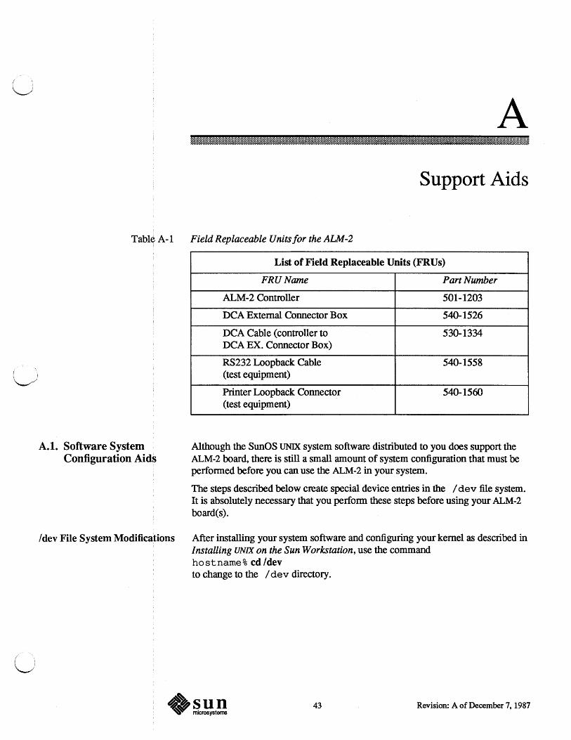
Table A-1 Field Replaceable Units for the ALM-2
A.1. Software System Configuration Aids
List of Field Replaceable Units (FR Us)
FRUName Part Number
ALM-2 Controller 501-1203
DCA External Connector Box 540-1526
DCA Cable (controller to 530-1334 DCA EX. Connector Box)
RS232 Loopback Cable 540-1558 (test equipment)
Printer Loopback Connector 540-1560 (test equipment)
Although the SunOS UNIX system software distributed to you does support the ALM-2 board, there is still a small amount of system configuration that must be performed before you can use the ALM-2 in your system.
The steps described below create special device entries in the I dev file system. It is absolutely necessary that you perform these steps before using your ALM-2 board(s).
/dev File System Modifications After installing your system software and configuring your kernel as described in Installing UNIX on the Sun Workstation, use the command hostname% cd /dev to change to the I dev directory.
43 Revision: A of December 7, 1987

44 16 Channel Asynchronous Line Multiplexer-2 Installation Notes
Determine how many ALM-2 boards are present in your system. (There will be between 1and4.) Run MAKEDEV with arguments corresponding to the boards in your system. Examples are shown below:
NOTE The command MAKEDEV is used to create the necessary special device entries for Sun standard and optional hardware. Also, the ALM-2 is known internally to the system as mcp.
Results of the Previous Step The previous step will have created a set of device entries of the form /dev/ttyxy where x will be one of the letters h, i, j, or k. These letters refer to each ALM-2 board: h refers to the first board (mcpO), i refers to the second board, and so on. y is a hexadecimal digit (in the range 0-9 a-f) which specifies which of the sixteen serial lines on an ALM-2 board is being accessed. Thus the third serial line on the third board is I dev /ttyj 2, and the twelfth serial line on the first board is /dev/ttyhb.
!~ )
For more information on installing modems, configuring terminal lines, and so !~ on, refer to System Administration for the Sun Workstation-Adding Hardware to Your System.
/~ I
Revision: A of December 7, 1987

( .
\__,,,i
Revision History
Dash Revision Number
01 1
01 2
01 3
02 50
05 A
L~
(_,1
Date Comments
March 13, 1987 Review Copy
April 10, 1987 Review Copy
June 6, 1987 Review Copy
September 11, 1987 Inclusion of Field Service Data
December 7, 1987 Production Release
Revision: A of December 7, 1987

",~ \ /

Corporate Headquarters Sun Microsystems, Inc. 2550.Garcia Avenue Mountain View, CA 94043 415 960-1300 TLX 37-29639 For U.S. Sales Office locations, call: 800821-4643 In CA: 800 821-4642
European Headquarters Sun Microsystems Europe, Inc. Sun House 31-41 Pembroke Broadway Camberley Surrey GU15 3XD England 027662111 TLX859017
Australia: (02) 436 4699 Canada: 416 477-6745 France: ( 1) 46 30 23 24 Germany: (089) 95094-0 Japan: (03) 221-7021 Nordic Countries: (08) 764 78 10 Switzerland: (1) 82 89 555 The Netherlands: 02155 24888 UK: 0276 62111
Europe, Middle East, and Africa, call European Headquarters: 027662111
Elsewhere in the world, call Corporate Headquarters: 415 960-1300 Intercontinental Sales