Embed Size (px)
Citation preview

Mälardalen University Licentiate ThesisNo.44
A Software ComponentTechnology for Vehicle
Control Systems
Mikael Åkerholm
February 2005
Department of Computer Science and ElectronicsMälardalen University
Västerås, Sweden

Copyright c© Mikael Åkerholm, 2005ISSN 1651-9256ISBN 91-88834-92-1Printed by Arkitektkopia, Västerås, SwedenDistribution: Mälardalen University Press
Abstract
Software is fantastic! Numereous modern high-tech products incorporate soft-ware. This thesis focus on software for vehicles. As high-tech products, mod-ern vehicles contain much software that provides advanced functionality, e.g.,efficient engine control, anti-spin systems, and adaptive-cruise control.
However, software engineering is not without problems! Software can con-tain errors, is often delivered later than promised and the cost of its devel-opment constitutes a major part of the total development cost of the vehicle.These problems are consequences of the complexity of the systems we buildwith software, in combination with the immaturity of an evolving discipline.
We therefore need improved approaches to software engineering. Comp-onent-based software engineering is a promising approach. It is analogous withapproaches used in other engineering domains. For examples, mechanical en-gineers build systems using well-specified components such as nuts and bolts,and the building industry uses components as large as walls and roofs (in turnassembled from smaller components). It has proven to be effective in applica-tion domains such as desktop and web-applications. However, it has not yetbeen widely adopted for use in the development of vehicular software; one ofthe reasons being that the commercial component technologies are developedspecifically for other domains and to support other types of applications.
This research aims at developing a component technology for embeddedcontrol systems in vehicles. Such a technology would enable software engi-neers in the vehicular domain to make use of component-based software engi-neering. We have addressed questions concerning quality attributes, and howcomponent-based applications should be built and modelled, in the context ofvehicular systems. Furthermore, based on our answers we have implemented,and evaluated a prototype component technology in cooperation with industry.The results confirm the suitability of our prototype, but also show that it mustbe further developed if it is to meet wider industrial requirements.
i


Till Jenny och Lucas

Preface
I have learned much during my two years as Ph.D. student, but most importantduring the journey has been all workmates that has made it such a good and funtime. Thank you all! That include all personnel at the Department of ComputerScience and Engineering, in the SAVE project, and people at companies I havebeen in contact with.
I especially want to thank my supervisors Prof. Ivica Crnkovic and Dr.Kristian Sandström. I have really appreciated to work with you, you are thebest! I also want thank Prof. Hans Hansson, Dr. Mikael Nolin, and Prof.Christer Norström for your advices and invaluable guidance during the time.
This work had not been possible without all fruitful cooperation and dis-cussions with my fellow Ph.D. students. The closest cooperation has been withJohan Fredriksson and Anders Möller. Thank you both!
Thanks also to Jörgen Hansson and Ken Lindfors at CC Systems for invit-ing us to test our ideas. To Johan Strandberg and Fredrik Löwenhielm at CCSystems for all time and energy spent on all our technical questions. Amongall helpful people I have met at different companies I want to thank JoakimFröberg, Jakob Axelsson, Mattias Ekman, Ola Larses, Bo Neidenström, andBertil Emmertz, for your time discussing my questions.
Finally, I want to thank my mother and father, relatives and friends, for allyour love and support.
Mikael ÅkerholmVästerås, January, 2005
v

List of Publications
Reports included in the thesis
Conferences and Workshops
Paper A Anders Möller, Mikael Åkerholm, Johan Fredriksson, and MikaelNolin, Evaluation of Component Technologies with Respect to IndustrialRequirements, In Euromicro Conference, Component-Based SoftwareEngineering Track Rennes, France, August 2004.
This paper is an evaluation of the suitability of exiting component tech-nologies for vehicular systems. The evaluation is based on a literaturesurvey of existing component technologies for embedded systems, anda study based on interviews capturing requirements on component tech-nologies from the vehicle industry.
Mikael’s part of the work has been to provide knowledge about the com-ponent technologies and participate in the evaluation process. He hasnot participated in collection of the industrial requirements, but he hasadopted and used the requirements in this work.
Paper B Mikael Åkerholm, Johan Fredriksson, Kristian Sandström, and IvicaCrnkovic, Quality Attribute Support in a Component Technology for Ve-hicular Software, In Fourth Conference on Software Engineering Re-search and Practice in Sweden Linköping, Sweden, October 2004.
This paper is based on a survey were representatives from different ve-hicular companies have placed priorities on a list of quality attributes.The paper presents the results of the survey, and in addition, a discus-sion of how the quality attributes could be supported by a componenttechnology.
vii
viii
Mikael has been involved in all parts of the work in this paper; he hasinitiated the study and led the process.
Paper C Hans Hansson, Mikael Åkerholm, Ivica Crnkovic, and Martin Törn-gren, SaveCCM - a component model for safety-critical real-time sys-tems, In Euromicro Conference, Special Session Component Models forDependable Systems Rennes, France, September 2004.
This paper presents the SaveCCM component model, intended for em-bedded control applications in vehicular systems. SaveCCM is a simplemodel in which flexibility is limited to facilitate analysis of real-time anddependability.
This paper is based on discussions within a group of researchers’, evenlarger than the set of authors. Mikael has participated in the discussions,and in the writing process.
Paper D Kristian Sandström, Johan Fredriksson, and Mikael Åkerholm, In-troducing a Component Technology for Safety Critical Embedded Real-Time Systems, In International Symposium on Component-based Soft-ware Engineering (CBSE7) Edinburgh, Scotland, May 2004.
In this paper we show how to use component based software engineeringfor low footprint embedded systems. The key concept is to provide ex-pressive design time models and yet resource effective run-time modelsby statically resolve resource usage and timing by powerful compile-time techniques.
The compile-time method is based on earlier research, in particular ex-periences from Kristian’s (first author) previous work. Mikael has beeninvolved in all parts of the work, with focus on the component modeland compile-time step.
Paper E Mikael Åkerholm, Anders Möller, Hans Hansson, and Mikael Nolin,Towards a Dependable Component Technology for Embedded SystemApplications, In Tenth IEEE International Workshop on Object-orientedReal-time Dependable Systems (WORDS2005), Sedona, Arizona, febru-ary, 2005
This paper describes a prototype component technology developed forcontrol applications in vehicles. The component technology has beenevaluated with an application in cooperation with industry.
Mikael’s main contribution to this work is implementation of the com-ponent model, and the compile-time allocation to the operating systems.
ix
There has been an equal amount of efforts between Anders and Mikaelin implementation of the test application, and evaluation of the result.
Other reports, not included in the thesis
Conferences and Workshops
• Jan Carlson, and Mikael Åkerholm, An event algebra extension of thetriggering mechanism in a component model for embedded systems, InFormal Foundations of Embedded Software and Component-Based Soft-ware Architectures (FESCA), Edinburgh, Scotland, April 2005.
• Johan Fredriksson, Mikael Åkerholm, and Kristian Sandström, Calcu-lating Resource Trade-offs when Mapping Component Services to Real-Time Tasks, In Fourth Conference on Software Engineering Researchand Practice in Sweden Linköping, Sweden, October 2004.
• Anders Möller, Mikael Åkerholm, Johan Fredriksson, and Mikael Nolin,Software Component Technologies for Real-Time Systems - An IndustrialPerspective, In WiP Session of Real-Time Systems Symposium (RTSS)Cancun, Mexico, December 2003.
• Johan Fredriksson, Mikael Åkerholm, Kristian Sandström, and RaduDobrin, Attaining Flexible Real-Time Systems by Bringing Together Com-ponent Technologies and Real-Time Systems Theory, In Proceedings ofthe 29th Euromicro Conference, Component Based Software Engineer-ing Track Belek, Turkey, September 2003.
• Tobias Samuelsson, Mikael Åkerholm, Peter Nygren, Johan Stärner, andLennart Lindh, A Comparison of Multiprocessor Real-Time OperatingSystems Implemented in Hardware and Software, In International Work-shop on Advanced Real-Time Operating System Services (ARTOSS)Porto, Portugal, July 2003.
• Ivica Crnkovic, Igor Cavrak, Johan Fredriksson, Rikard Land, MarioZagar, and Mikael Åkerholm, On the Teaching of Distributed SoftwareDevelopment, In 25th International Conference Information TechnologyInterfaces Dubrovnik, Croatia, June 2003.

x
Technical Reports
• Mikael Åkerholm, Anders Möller, Hans Hansson, and Mikael Nolin,SaveComp - a Dependable Component Technology for Embedded Sys-tems Software, MRTC Report ISSN 1404-3041 ISRN MDH-MRTC-165/2004-1-SE, Mälardalen Real-Time Research Centre, Mälardalen Univer-sity, December 2004.
• Mikael Åkerholm, Kristian Sandström, and Johan Fredriksson, Interfer-ence Control for Integration of Vehicular Software Components, MRTCReport ISSN 1404-3041 ISRN MDH-MRTC-162/2004-1-SE,MälardalenReal-Time Research Centre, Mälardalen University, May 2004.
• Anders Möller, Mikael Åkerholm, Johan Fredriksson, and Mikael No-lin, An Industrial Evaluation of Component Technologies for Embedded-Systems, MRTC Report ISSN 1404-3041 ISRN MDH-MRTC-155/2004-1-SE, Mälardalen Real-Time Research Centre, Mälardalen University,February 2004.
• Mikael Nolin, Johan Fredriksson, Jerker Hammarberg, Joel G Huselius,John Håkansson, Annika Karlsson, Ola Larses, Markus Lindgren, GoranMustapic, Anders Möller, Thomas Nolte, Jonas Norberg, Dag Nyström,Aleksandra Tesanovic, and Mikael Åkerholm, Component Based Soft-ware Engineering for Embedded Systems - A literature survey, MRTCReport ISSN 1404-3041 ISRN MDH-MRTC-102/2003-1-SE,MälardalenReal-Time Research Centre, Mälardalen University, June 2003.
• Ivica Crnkovic, Goran Mustapic, and Mikael Åkerholm, Modern tech-nologies for modeling and development of process information systems,MRTC Report ISSN 1404 - 3041 ISRN MDH - MRTC - 100/2003 -1 - SE, Mälardalen Real-Time Research Centre, Mälardalen University,May 2003.
• Mikael Åkerholm, and Johan Fredriksson, A Sample of Component Tech-nologies for Embedded Systems, Technical Report, Mälardalen Univer-sity, November 2004.

Contents
I Thesis 1
1 Introduction 31.1 Component Technology Terminology . . . . . . . . . . . . . 5
1.2 Vehicle Electronic Systems . . . . . . . . . . . . . . . . . . . 7
1.3 Outline of Thesis . . . . . . . . . . . . . . . . . . . . . . . . 9
2 Research Summary 112.1 Methodology . . . . . . . . . . . . . . . . . . . . . . . . . . 11
2.2 Problem Definition . . . . . . . . . . . . . . . . . . . . . . . 12
2.3 Research Questions . . . . . . . . . . . . . . . . . . . . . . . 14
2.4 Contributions . . . . . . . . . . . . . . . . . . . . . . . . . . 16
3 Related work 213.1 Component Technologies in Different Domains . . . . . . . . 21
3.1.1 Vehicular Systems . . . . . . . . . . . . . . . . . . . 21
3.1.2 Consumer Electronics . . . . . . . . . . . . . . . . . 22
3.1.3 Automation Systems . . . . . . . . . . . . . . . . . . 23
3.2 Domain Independent CBSE Research . . . . . . . . . . . . . 25
3.2.1 Quality Attribute Prediction . . . . . . . . . . . . . . 25
3.2.2 Adopting General Purpose Technologies . . . . . . . . 26
4 Conclusions and Future Work 29
Bibliography 31
xi

xii Contents
II Included Papers 37
5 Paper A:Evaluation of Component Technologies with Respect to IndustrialRequirements 395.1 Introduction . . . . . . . . . . . . . . . . . . . . . . . . . . . 415.2 Requirements . . . . . . . . . . . . . . . . . . . . . . . . . . 42
5.2.1 Technical Requirements . . . . . . . . . . . . . . . . 425.2.2 Development Requirements . . . . . . . . . . . . . . 445.2.3 Derived Requirements . . . . . . . . . . . . . . . . . 45
5.3 Component Technologies . . . . . . . . . . . . . . . . . . . 465.3.1 PECT . . . . . . . . . . . . . . . . . . . . . . . . . . 475.3.2 Koala . . . . . . . . . . . . . . . . . . . . . . . . . . 485.3.3 Rubus Component Model . . . . . . . . . . . . . . . 495.3.4 PBO . . . . . . . . . . . . . . . . . . . . . . . . . . . 505.3.5 PECOS . . . . . . . . . . . . . . . . . . . . . . . . . 515.3.6 CORBA Based Technologies . . . . . . . . . . . . . 52
5.4 Summary of Evaluation . . . . . . . . . . . . . . . . . . . . 535.5 Conclusion . . . . . . . . . . . . . . . . . . . . . . . . . . . 55Bibliography . . . . . . . . . . . . . . . . . . . . . . . . . . . . . 55
6 Paper B:Quality Attribute Support in a Component Technology for Vehicu-lar Software 596.1 Introduction . . . . . . . . . . . . . . . . . . . . . . . . . . . 616.2 Method . . . . . . . . . . . . . . . . . . . . . . . . . . . . . 626.3 Results . . . . . . . . . . . . . . . . . . . . . . . . . . . . . . 656.4 Discussion of the results . . . . . . . . . . . . . . . . . . . . 67
6.4.1 Safety . . . . . . . . . . . . . . . . . . . . . . . . . . 676.4.2 Reliability . . . . . . . . . . . . . . . . . . . . . . . . 686.4.3 Predictability . . . . . . . . . . . . . . . . . . . . . . 696.4.4 Usability . . . . . . . . . . . . . . . . . . . . . . . . 696.4.5 Extendibility . . . . . . . . . . . . . . . . . . . . . . 706.4.6 Maintainability . . . . . . . . . . . . . . . . . . . . . 706.4.7 Efficiency . . . . . . . . . . . . . . . . . . . . . . . . 716.4.8 Testability . . . . . . . . . . . . . . . . . . . . . . . . 716.4.9 Security . . . . . . . . . . . . . . . . . . . . . . . . . 726.4.10 Flexibility . . . . . . . . . . . . . . . . . . . . . . . . 72
Contents xiii
6.4.11 Quality Attribute Support in a Component Technologyfor the Automotive Domain . . . . . . . . . . . . . . 72
6.5 Future Work . . . . . . . . . . . . . . . . . . . . . . . . . . . 74
6.6 Conclusions . . . . . . . . . . . . . . . . . . . . . . . . . . . 74Bibliography . . . . . . . . . . . . . . . . . . . . . . . . . . . . . 74
7 Paper C:SaveCCM a Component Model for Safety-Critical Real-Time Sys-tems 797.1 Introduction . . . . . . . . . . . . . . . . . . . . . . . . . . . 81
7.2 Related work . . . . . . . . . . . . . . . . . . . . . . . . . . 82
7.3 The SAVE project . . . . . . . . . . . . . . . . . . . . . . . . 83
7.4 Application Characteristics . . . . . . . . . . . . . . . . . . . 84
7.5 The SAVEComp Component Model . . . . . . . . . . . . . . 86
7.5.1 Architectural Elements . . . . . . . . . . . . . . . . . 86
7.5.2 Specification and Composition Language . . . . . . . 897.5.3 Graphical Language . . . . . . . . . . . . . . . . . . 91
7.5.4 Simple examples . . . . . . . . . . . . . . . . . . . . 92
7.6 The Cruise Control Example . . . . . . . . . . . . . . . . . . 94
7.7 Conclusions and further work . . . . . . . . . . . . . . . . . . 98
Bibliography . . . . . . . . . . . . . . . . . . . . . . . . . . . . . 98
8 Paper D:Introducing a Component Technology for Safety Critical Embed-ded Real-Time Systems 1018.1 Introduction . . . . . . . . . . . . . . . . . . . . . . . . . . . 103
8.2 Component Technology . . . . . . . . . . . . . . . . . . . . . 105
8.3 Component Model . . . . . . . . . . . . . . . . . . . . . . . 1068.4 Model Transformation . . . . . . . . . . . . . . . . . . . . . 110
8.4.1 Task Allocation . . . . . . . . . . . . . . . . . . . . . 111
8.4.2 Attribute Assignment . . . . . . . . . . . . . . . . . . 112
8.4.3 Real-Time Analysis . . . . . . . . . . . . . . . . . . . 115
8.5 Synthesis . . . . . . . . . . . . . . . . . . . . . . . . . . . . 116
8.6 Conclusions and Future Work . . . . . . . . . . . . . . . . . . 118
Bibliography . . . . . . . . . . . . . . . . . . . . . . . . . . . . . 118
xiv Contents
9 Paper E:Towards a Dependable Component Technology for Embedded Sys-tem Applications 1239.1 Introduction . . . . . . . . . . . . . . . . . . . . . . . . . . . 1259.2 CBSE for Embedded Systems . . . . . . . . . . . . . . . . . 1269.3 Our Component Technology . . . . . . . . . . . . . . . . . . 127
9.3.1 Design-Time - The Component Model . . . . . . . . . 1299.3.2 Compile-Time Activities . . . . . . . . . . . . . . . . 1329.3.3 The Run-Time System . . . . . . . . . . . . . . . . . 134
9.4 Application Example . . . . . . . . . . . . . . . . . . . . . . 1359.4.1 Introduction to ACC functionality . . . . . . . . . . . 1359.4.2 Implementation using SaveCCM . . . . . . . . . . . . 1369.4.3 Application Test-Bed Environment . . . . . . . . . . 138
9.5 Evaluation and Discussion . . . . . . . . . . . . . . . . . . . 1389.5.1 Structural Properties . . . . . . . . . . . . . . . . . . 1399.5.2 Behavioural Properties . . . . . . . . . . . . . . . . . 1409.5.3 Process Related . . . . . . . . . . . . . . . . . . . . . 141
9.6 Conclusions and Future Work . . . . . . . . . . . . . . . . . . 141Bibliography . . . . . . . . . . . . . . . . . . . . . . . . . . . . . 142

I
Thesis
1

Chapter 1
Introduction
Building systems from components is an old engineering practice. Cars havebeen assembled from components since Henry Ford built the first T-Ford at thebeginning of the 20th century. The component-based assembly of computerscan be considered to have been begun in the 1950’s when several transistorswere first integrated in a single circuit. Software itself has also been built formany years using a component-based strategy. The development of complexprograms has been made possible through the development of sub-programs,in a system decomposition process, e.g., client-server, and object-oriented de-sign [1]. However, with a few exceptions e.g., mathematical and graphicalfunction-libraries, the component-based strategy has, historically, not been assuccessful in the software industry, as in the examples from other industries,previously mentioned. This is, perhaps, mostly because attempts to reuse soft-ware components have resulted in serious problems due to architectural mis-matches between components or components and the surrounding environment[2]. Before software engineering can be a mature, well founded discipline,these issues must be resolved. As stated by Szyperski [3]:
Building, using and reusing components is what all other engi-neering disciplines have done when they have become mature, thesoftware discipline should also follow.
Szyperski
Research in the Component-Based Software Engineering (CBSE) commu-nity is concerned with developing theories, processes, technologies, and tools
3
4 Chapter 1. Introduction
supporting and enhancing a component-based design strategy for software [4].In an idealized view of traditional software development, the software is devel-oped in a sequential process from requirement definition to delivery. CBSE, onthe other hand, includes two separate development processes. A component-based approach distinguishes component development from system develop-ment. Component development is the process of creating components that canbe used and reused in many applications. System development with compo-nents is concerned with assembling components into applications that meetthe system requirements. The overall principles of CBSE are realised throughcomponent technologies. A component technology provides support for as-sembling component-based software. It includes models for how componentscan be assembled, as well as the necessary run-time support that includes com-ponent deployment and interoperation between components. Some of the mostwidely known component technologies are COM [5] and .NET [6] from Mi-crosoft, and Enterprise JavaBeans [7] from Sun Microsystems.
CBSE has been successfully used in several software development projects,mainly in the domains of desktop and e-business applications, less frequentlyin embedded applications. This thesis addresses the problem of defining acomponent technology suitable for the development of software for embeddedcontrol-systems in vehicles. The underlying assumption is that one reason forthe limited success of CBSE practice in the embedded systems domain hasbeen the inability of commercially available component technologies to pro-vide solutions that meet typical requirements of embedded applications e.g.,resource-efficiency (the consumption of a minimum of resources in achievingan objective), predictability, and safety. In brief, we have addressed the prob-lem through development of a prototype component technology for embeddedvehicular systems, and the suitability of the result has been evaluated by meansof an experiment in cooperation with industry.
The work has been carried out within the SAVE project [8]. The main goalof the project is to begin establishing an engineering discipline for system-atic development of component-based software for safety-critical embeddedsystems. The focus of the project is on a single application area (vehicularsystems), to reduce the overall project complexity to a manageable level. Thecomponent-technology presented in this thesis can be seen as one of the coreparts of the project, other results from the project being integrated in futurework.
The two sections following immediately provide introductions to basic tech-nical concepts of component technologies, and vehicular systems, as a founda-tion for reading the rest of the thesis.
1.1 Component Technology Terminology 5
1.1 Component Technology Terminology
This section provides a brief introduction to central technical concepts of com-ponent technologies frequently used in the remainder of the thesis. For moreinformation about CBSE and component technologies refer to, e.g., Heinemanand Councill’s book [9], Szypeki’s book [3], or Crnkovic and Larsson’s book[4].
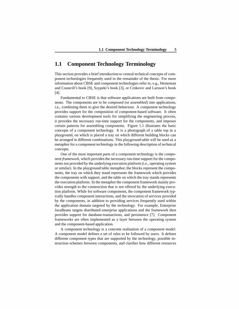
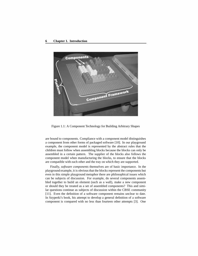
Fundamental to CBSE is that software applications are built from compo-nents. The components are to be composed (or assembled) into applications,i.e., combining them to give the desired behaviour. A component technologyprovides support for the composition of component-based software. It oftencontains various development tools for simplifying the engineering process,it provides the necessary run-time support for the components, and imposescertain patterns for assembling components. Figure 1.1 illustrates the basicconcepts of a component technology. It is a photograph of a table top in aplayground, on which is placed a tray on which different building blocks canbe arranged in different combinations. This playground table will be used as ametaphor for a component technology in the following description of technicalconcepts.
One of the most important parts of a component technology is the compo-nent framework, which provides the necessary run-time support for the compo-nents not provided by the underlying execution platform (i.e., operating systemor similar). In the playground table metaphor, the blocks represent the compo-nents, the tray on which they stand represents the framework which providesthe components with support, and the table on which the tray stands representsthe execution platform. In the metaphor the component framework mainly pro-vides strength to the construction that is not offered by the underlying execu-tion platform. While for software components, the component framework typ-ically handles component interactions, and the invocation of services providedby the components, in addition to providing services frequently used withinthe application domain targeted by the technology. For example, EnterpriseJavaBeans targets distributed enterprise applications and the framework thenprovides support for database-transactions, and persistence [7]. Componentframeworks are often implemented as a layer between the operating systemand the component-based application.
A component technology is a concrete realisation of a component model.A component model defines a set of rules to be followed by users. It definesdifferent component types that are supported by the technology, possible in-teraction schemes between components, and clarifies how different resources
6 Chapter 1. Introduction
Components
Component Framework
Platfo
rm
Components
Component Framework
Platfo
rm
Figure 1.1: A Component Technology for Building Arbitrary Shapes
are bound to components. Compliance with a component model distinguishesa component from other forms of packaged software [10]. In our playgroundexample, the component model is represented by the abstract rules that thechildren must follow when assembling blocks because the blocks can only beassembled in a certain pattern. The supplier of the blocks also follows thecomponent model when manufacturing the blocks, to ensure that the blocksare compatible with each other and the tray on which they are supported.
Finally, software components themselves are of basic importance. In theplayground example, it is obvious that the blocks represent the components buteven in this simple playground metaphor there are philosophical issues whichcan be subjects of discussion. For example, do several components assem-bled together to build an element (such as a wall), make a new componentor should they be treated as a set of assembled components? This and simi-lar questions continue as subjects of discussion within the CBSE community[11]. Even the definition of a software component remains unclear to date.In Szyperki’s book, his attempt to develop a general definition of a softwarecomponent is compared with no less than fourteen other attempts [3]. One
1.2 Vehicle Electronic Systems 7
can always question the need for one common component definition, since thecomponent model defines components for a particular technology. Technolo-gies might in turn be intended for different purposes, and as a consequence,different types of components might be suitable. Heineman and Councill pro-pose the following definition, extracted from other definitions, which tries tobe consistent with the majority of these [9]:
A software component is a software element that conforms to acomponent model and can be independently deployed and com-posed without modification according to a composition standard.
Heineman and Councill
From a practical point of view, components should have well-specified in-terfaces and be easy to understand, adapt and transfer between organisations.Components should have well-specified interfaces, since CBSE relies heav-ily on interfaces. The interfaces must handle all properties that lead to inter-component dependencies, since the rest of the component is often hidden fromthe developer. Components should also be easy to understand, since once cre-ated, they are intended to be reused by other developers. The possibilities ofreuse of a component are enhanced if it is easy to adapt the component for usein different environments and in combination with different software architec-tures and other components.
1.2 Vehicle Electronic Systems
The application domain in this thesis is embedded control systems in modernvehicles, e.g., in passenger cars, trucks, and heavy vehicles. Modern vehiclescontain electronics that can be classified as follows [12]:
Power train and chassis systems. These include systems that are highly crit-ical for the vehicles functionality, controlling, e.g., engine, brakes, andsteering. They are characterised by high demands on safety, reliability,and hard real-time constraints.
Cabin systems. Less critical systems, that also are core parts of the function-ality, e.g., dashboard instruments, electrically powered windows, and air-conditioning.
8 Chapter 1. Introduction
Infotainment systems. Systems dedicated to information processing, enter-tainment, and communication with others outside the vehicle, e.g., audio,video, and satellite-navigation systems. These systems are not closelyintegrated with the core functionality of the vehicle and are easier to re-place, supplement and remove.
We concentrate on the power train and chassis, and use the common termvehicular systems, when referring to these systems in different classes of ve-hicles, e.g., cars, and heavy vehicles. The focus is chosen because these sys-tems are the most critical for the functionality of the vehicle, with maximumdemands on qualities beyond functionality such as timeliness, safety, and re-liability. It is these qualities that are not addressed by existing commercialcomponent technologies (e.g., .NET [6], and Enterprise JavaBeans [7]), andconsequently cannot be developed with the existing commercial componenttechnologies. We observe however that the existing technologies might bewell-suited in the development of infotainment applications, which are simi-lar to desktop- and web-applications for personal computers.
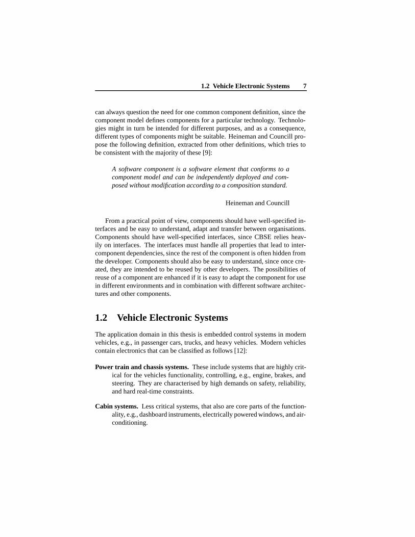
Figure 1.2: Overview of the electronic system architecture in Volvo XC90
1.3 Outline of Thesis 9
The physical architecture of the electronic system in vehicles is a complexdistributed computer system. The computer nodes are designated ElectronicControl Units (ECUs), and are often developed by different vendors and usedifferent hardware. The ECUs are interconnected by one or several networks,and often different network technologies are used within the same vehicle. Asexamples, Volvo Truck Corporation uses two different network technologiesand has six to eight external suppliers of ECUs, depending on the type of ve-hicle, and Volvo Car Corporation uses four different network technologies, de-pending on model, and has more than ten suppliers of ECUs [13]. In figure 1.2from [13], the electronic architecture of a Volvo XC90 is shown. The figureshows the approximate location of the forty ECUs in the vehicle, and to whichnetworks each ECU is connected. The location of each ECU is primarily deter-mined by where the controlled object is in the vehicle to minimize the lengthof wiring to sensors and actuators, e.g., the engine controller is placed close tothe engine. Interconnection networks permit the implementation of functionsthrough collaboration between several ECUs, e.g., the Electronic Stability Pro-gram (ESP) developed by Mercedes-Benz [14]. ESP utilises ECUs controllingthe engine and brakes, to assist the driver in situations in which the vehicleskids.
1.3 Outline of Thesis
The remainder of Part I is outlined as follows. Chapter 2 is a summary of theresearch. It contains research questions, and summarizes the contributions ofthe published papers constituting this licentiate thesis. In Chapter 3, relatedwork is summarized. Finally, Chapter 4 contains conclusions and discussespossibilities for future work. Part II, contains the papers included in Chapter 5to Chapter 9.

Chapter 2
Research Summary
This chapter contains a summary of the research methods, questions, and con-tributions relevant to the thesis. The research methodology is described in Sec-tion 2.1. Section 2.2 presents the general picture, i.e., the real-world problemthat the contribution of this thesis helps to solve. Section 2.3 presents the focusof the thesis, in terms of research questions that define the research setting. Fi-nally, Section 2.4 presents the contributions of the thesis, how the results havebeen obtained, and how they have been evaluated.
2.1 Methodology
We have adopted the research methodology described by Shaw in [15]. Themethodology is derived from experience of more than a decade of the actualperformance of software architecture research. The main activities are:
1. Identification of research problems from real-world software engineer-ing. Such problems are often complex, and not suitable subjects fordirect research. The research problem is discussed in Section 2.2.
2. Transfer the problem to a research setting, and define research questions.The research setting is a simplification of the real-world problem, oftenfocusing on certain aspects of the problem. There are several differentclasses of research settings, each associated with different types of prob-lems, e.g., determining the feasibility of an approach, finding methods toaccomplish some goal, or selection between alternative approaches. Thedetails are discussed in Section 2.3.
11
12 Chapter 2. Research Summary
3. Answering the research questions. In this phase, the work is aimed at awell-defined problem suitable for research, and, depending on the natureof the problem, different methods can be selected. There is a wide rangeof different methods, from descriptive models of observations to the de-velopment of new techniques. Section 2.4 describes the methods and theanswers obtained in this thesis.
4. The research results are validated by demonstrating that the results sat-isfactorily answer the research questions. This can be done in differentways, e.g., by formal proofs, by implementation of a prototype, by de-scribing experiences, and by persuasion through argumentation. Valida-tion is also addressed in Section 2.4.
2.2 Problem Definition
This thesis addresses the problem of defining a component technology for em-bedded control systems in vehicles. There are several challenges related tothe problem, in an area relatively unexplored in comparison with componenttechnologies for desktop- and web-applications.
The existing commercial component technologies have been developedwithin the PC domain, which is a domain with requirements fundamentallydifferent from those of vehicular systems. In comparison with PC software, thesafety requirement for vehicular software is much greater. Unsafe behaviourof a moving vehicle can result in injury, even death, to persons. The demandfor software reliability is greater since failure could result in financial loss orloss of goodwill. A minimum of resource consumption is required to minimizevehicle production-cost. Vehicles are often produced in large numbers, in thecase of cars, often of the order of millions per year. Finally, vehicular systemsare real-time systems, due to temporal requirements based on the vehicle func-tions. Consider the software for an Anti-lock Brake System (ABS). When thebrake on one wheel locks, the system must release the brake pressure withina certain time for the driver to remain in control of the steering. On the otherhand, certain systems cannot respond too soon. When a collision occurs, thesoftware controlling an air-bag must be activated within a certain time-interval;it is useless if it is activated too late or too early.
The overall industrial problem is to define a component technology thatprovides methods to accomplish the main application requirements as dis-cussed above, and also supports typical engineering activities in the vehicular

2.2 Problem Definition 13
domain. Wolf [16] defines the primary objectives for engineers in the embed-ded systems domain, in which vehicular systems are a specialisation, with thesubjects: architecture, analysis, modelling, verification, and application orien-tation. Some of these subjects are involved in all software engineering, butthe approach to them and their purposes distinguishes the software in embed-ded systems from other classes of software. Each subject might in turn havea different importance and slightly different meaning in different domains ofembedded systems.
System Architecture. Architectures for embedded systems are defined to servethe functions of a particular application using resources efficiently. Thiscalls for specialised component technologies which use resources effi-ciently, to meet the demands of the vehicular domain, not for a broadrange of (embedded) applications [17]. This argument is also supportedby Larn and Vickers when they describe the risk of performance compro-mises in the architecture, due to support for reusability of general com-ponents [18]. Furthermore, Crnkovic identifies key priorities in researchto establish a CBSE engineering discipline for embedded systems. Oneof these is the development of component run-time frameworks whichrequire a minimum of resources [19].
Analysis. A suitable component technology should provide support for rea-soning about such quality attributes as the performance and size of sys-tems at an early stage in the design process. This is a goal the designersof embedded systems strive to achieve. The need for predictable compo-nent technologies in the automotive domain is stressed in, e.g., [20, 19].
Modelling. To simplify analysis and understanding of the system, developersneed models of different aspects of applications at a higher abstractionlevel than the source code provides. For instance, architectural modelsfor analysing and understanding basic functionality, timing models forreal-time analysis, and behaviour models of the system in its intendedenvironment for safety analysis. In a component-based approach, the de-scription of the component assembly serves as an architectural model ofthe application. The architectural model can be supplemented with othermodelling aspects, or with additional models. Möller et al., have ob-tained further requirements of the component modelling language fromindustry, observing that it should follow commercially supported stan-dards [20].
14 Chapter 2. Research Summary
Verification. Applications must be verified in accordance with functional andnon-functional specifications. For a component technology, predictabil-ity to enable the use of formal methods, complemented by practicallyoriented simulation and test support are needed to meet these constraints.Much research performed by the CBSE community addresses the predic-tion of different quality attributes of component based applications, e.g.,[21, 22, 23, 24, 25].
Application orientation. The control of the vehicle dynamics is not the onlyfunctionality to be considered. The control-related part of the applica-tion is its core but is in fact only a small part of the whole vehicle ap-plication. The component technology must provide support for morethan the implementation of control systems. Typical functionality thatcoexists in the same environment includes fault tracing and handling,monitoring and logging for diagnostics during service, and human inter-action through displays and controls. There is an increasing number ofinfotainment applications in modern vehicles, but this functionality oftenremains separate from the vehicle control system.
2.3 Research Questions
The research contributes towards a solution to the problem described in thepreceding section. We have limited the complexity of the real-world problem,through a research setting defined by the research questions. The research isbased on two fundamental assumptions that motivated the thesis:
1. The use of CBSE in the domain is limited by the inability of existingcommercial technologies to support the requirements of embedded ve-hicular applications.
2. Despite the different demands on embedded vehicular software as com-pared with other software, CBSE is an attractive engineering approach.
As noted in the preceding section, commercially available technologies arenot suitable for the vehicular domain, which is a logical reason for the compa-nies to approach CBSE with caution.
The validity of the second concept is demonstrated however by the effortsthe vehicular industry is actually making in CBSE related projects, e.g., EAST[26], and AUTOSAR [27]. The amount of functionality implemented with
2.3 Research Questions 15
software in vehicles continues to increase leading to increased software com-plexity. Combined with requirements for lower costs and shorter developmenttime (as in all industrial segments), there is a need for better systematic engi-neering approaches. CBSE is one candidate approach but, however, for it to beutilised efficiently, a mature component technology with good domain-specificsupport is needed.
With these assumptions in mind, the main research question (Q) is formu-lated as follows:
How can a component technology for vehicular software be implemented, toprovide the functionality desired for vehicular applications, with support forthe important quality attributes essential in the vehicular domain?
(Q)
The main question is broad, and admits the possibility of different answers.We intend to explore one of the possibilities, but to do this thoroughly by an-swering separately a number of sub-questions addressing component models,frameworks, and quality attributes. The sub-questions are formulated:
Which quality attributes are the most important in the vehicular domain, andhow do they relate to a component technology?
(Q1)
Quality attributes define the quality of software. Quality attributes for theevaluation of software have been standardised in [28]. The top-level attributesin the standard are functionality, reliability, usability, efficiency, maintainabil-ity, and portability. This sub-question seeks to establish domain-specific prior-ities of different quality attributes, and it is reasonable to expect that attributescan have different priorities in different software domains. The second partof the question addresses the relations between a component technology andthe quality attributes that are important in the domain. We expect that somequality attributes are more dependent on the choice of component technologythan others. Furthermore, it is known that quality attributes are interdependent,and that some contradictoty attributes are difficult to support simultaneously[29, 30]. Therefore, the establishment of domain-specific attribute prioritiescan be used as guidance when resolving conflicts.
How can a component model support predictability of important quality at-
16 Chapter 2. Research Summary
tributes and be suitable for expressing common functionality in vehicular con-trol systems?
(Q2)
This question calls for an approach by defining components and possibili-ties for component interaction, with respect to ease of implementing vehicularcontrol systems, and support for prediction of quality attributes considered im-portant in the domain (identified in (Q1)). The general approach to increasingthe predictability of software is to limit its flexibility. For example, pre-run-time scheduling limits the arrangement of activities to a pre-defined schema.The execution path for such systems is easier to predict than that of flexiblerun-time scheduled systems. However, flexibility increases the possibilities forengineers when implementing applications. This question seeks the trade-offbetween the predictability desirable and the flexibility necessary when definingapplications in the context of vehicular control systems.
How can an efficient utilisation of resources be achieved in component basedapplications?
(Q3)
By resources we mean shared limited run-time resources, e.g., processorand memory capacity. Resource-efficiency, (the consumption of a minimum ofresources in achieving an objective) is a quality attribute that has received spe-cial attention in this work. This focus is based on the belief that poor resourceefficiency is an important reason for vehicular companies not choosing to uti-lize commercial component technologies. Commercial technologies are de-veloped for use with personal computers and network servers, where resourceconsumption is a minor concern, e.g., Enterprise JavaBeans in the J2EE 1.3.1release requires 128 MB RAM [31], while typical hardware used in vehicularsystems can have 128 kB [32].
2.4 Contributions
To address the above questions, we have conducted literature surveys, devel-oped new methods, implemented a prototype for evaluation, and also utilisedexperience from earlier work by senior researchers. The work has also includedindustrial involvement. Interviews with technical staff regarding current sys-tem engineering methods were carried out early in the project as orientation
2.4 Contributions 17
for the initial research steps. Representatives of different vehicular companieshave been consulted regarding the priority given to software quality attributes.Finally, validation of the early results has been performed in cooperation withindustry.
The contributions and validation of the research are presented with thequestions as starting points. The results provide answers to the research ques-tions, but are subject to certain limitations, which are also discussed and aresuitable for further research. There are more detailed presentations of the con-tributions in the five papers referred to in the presentation.
Contributions answering Q
How can a component technology for vehicular software be implemented, to provide thefunctionality desired for vehicular applications, with support for the important qualityattributes essential in the vehicular domain?
Paper A addresses the main question by evaluating existing componenttechnologies intended for embedded systems. The evaluation is based on a lit-erature survey of different component technologies [33]. The literature surveyis compared with a study based on interviews to determine the requirementsof the vehicle industry for component technologies [20]. One of our conclu-sions is that none of the technologies studied completely satisfies the industryrequirements. Furthermore, no single technology stands out as being a signifi-cantly better choice than the others; each technology has its own pros and cons.However, worth notice is that two of the technologies investigated (i.e. Koala[34], and Rubus CM [35]) are actually used successfully in practice by industrywithout meeting all the requirements specified in the evaluation.
The prototype component technology described and evaluated in Paper E,shows how far we have reached in finding an answer to the main question. Theprototype is based on the component model described in Paper C, and compile-time techniques from Paper D. The component technology was developed forcontrol applications in vehicles, providing both support for predictability ofquality attributes and typical functionality in vehicular control applications.The component technology has been evaluated with an application in coop-eration with industry. The conclusion from the evaluation is that our initialstudy provides positive evidence, but that the technology needs to be furtherdeveloped to be applicable in an industrial context.
There are several assumptions and limitations in the answer that need to beaddressed in future work. The suggested component technology is a promising
18 Chapter 2. Research Summary
prototype including only the core functionality. It needs to be extended withsupporting tools for modelling and configuration management. Furthermore,a vehicular function is often distributed across several interconnected physicalnodes. Support for distribution of components would therefore be a valuableextension of the prototype. The question also addresses support for importantquality attributes. This support has not been fully implemented and evaluated,but an initial suggestion is described in Paper B.
Contributions answering Q1
Which quality attributes are the most important in the vehicular domain, and how dothey relate to a component technology?
This question is the main topic of Paper B. The paper is based on a sur-vey in which representatives of different vehicle companies have allocated pri-orities in a list of quality attributes considered to be of particular interest tothem. In order to reduce the number of attributes, those with obvious similari-ties in their definitions have been grouped in more generic types of properties;e.g., portability and scalability are considered to be covered by maintainabil-ity. The result shows that the companies involved give approximately the samepriorities to quality attributes. Reasonably, the most important concerns arerelated to dependability characteristics, e.g., safety, and reliability. Usabilityis a property important to the customers but also crucial in competition on themarket. Slightly less important attributes are related to the product life cycle(extendibility, maintainability).
The second part of the paper continues with a discussion relating qualityattributes to a component technology, and a suggestion of quality attribute sup-port in a component technology suitable for the vehicle domain. In addition,it discusses where in the technology the support should be implemented: in-side or outside the components, in the component framework, on the systemarchitecture level, or if the quality attributes are usage-dependent.
There are several questions respecting the validity of the study. Is the listof quality attributes that we have given to the companies appropriate? Have wecaptured the companies view or the representatives view? Is it a coincidencethat we obtained similar priorities from the different companies in the study,or is it a common opinion? Even if such questions are motivated, the researchresults put focus on the main concerns. They can be used as initial guidance forfurther development of component technologies suitable for vehicular systems.To continue the investigation and resolve certain questions, a future workshop
2.4 Contributions 19
could be organized at which the representatives interviewed and possibly otherstakeholders from industry could discuss and expand upon the results.
Contributions answering Q2
How can a component model support predictability of important quality attributes inthe domain, and be suitable for expressing common functionality in vehicular controlsystems?
Paper C presents the SaveCCM component model, intended for embed-ded control applications in vehicular systems. SaveCCM is a simple model inwhich flexibility is limited to facilitate the analysis of real-time and depend-ability. The architectural elements are components, switches, and assemblies.Components are the basic units in a design, and shall give the desired function-ality. Switches are special components used to statically (during design-time),or dynamically (during run-time), (re)configure component interconnections.Assemblies represent sub-systems and are aggregated behaviour from a set ofcomponents, switches, and possibly other assemblies. The interface of all ar-chitectural elements is a set of ports, which are points of interaction betweenthe elements. We distinguish between input- and output-ports, and the com-plementary aspects data transfer (data-flow) and execution triggering (control-flow).
The component model has been designed to easily express common func-tionality in vehicular systems. Some specific examples of key functionality are:feedback control, system mode changes, and static configuration for product-line architectures.
The component model is limited to simplify future analysis of differentproperties, e.g., real-time, reliability, and safety properties. It may, however,be too restrictive, and should be expanded. Paper E contains an evaluation ofour prototype implementation of a component technology using the SaveCCMcomponent model, which we found to be sufficiently expressive. We studiedonly a single application, and are not able to generalise and claim that it is arepresentative case. If future studies indicate that we must extend SaveCCM,this will be done, maintaining predictability as far as possible.
Contributions answering Q3
How can resource efficiency of component-based applications be achieved?
20 Chapter 2. Research Summary
This question is mainly treated in Paper D. In commercial component tech-nologies the component-based approach is made possible by powerful run-timemechanisms, which for resource-limited systems have the disadvantage of in-creased resource utilisation. In this paper, we show how a component-basedapproach is permitted by the use of powerful compile-time techniques. The keyconcept is the clear distinctions between design-time, compile-time, and run-time. The method allows both expressive design-time models and resource-effective run-time models by statically resolving resource usage and timingduring compile-time. This results in a component technology with resource-effective mapping of a component model to a commercial real-time operatingsystem. The evaluation of the prototype technology in Paper E proves thatthe compile-time methods are able to generate resource-efficient systems fromcomponent-based designs.
The strategy is to resolve as much as possible during compile-time andto utilise resource-efficient platforms during execution. To further improveresource-efficiency, the compile-time mapping can be further optimised; moreefficient platforms (operating systems) will result in more efficient applica-tions. A drawback with the method (as with all compilation) is that traceabilitybetween the application behaviour during run-time and the design descriptionis decreased, since the compile-time method transforms the component-baseddesign to the execution model of the underlying operating-system. However,this problem is solvable with the techniques used today by debuggers to linkexecution behaviour to source code.
Chapter 3
Related work
Recently component technologies for different classes of embedded systemshave been developed both in academia and in industry. Some of them arediscussed in Section 3.1, together with related projects within the differentdomains. Section 3.2 addresses CBSE research not targeting particular do-mains, but that are important ingredients to enable CBSE for embedded sys-tems. We review basic research regarding predictability of quality attributes ofcomponent-based systems, and some efforts to enable use of existing commer-cial component technologies in embedded systems.
3.1 Component Technologies in Different Domains
In this section some examples of component technologies from different do-mains of embedded systems are discussed. We discuss vehicular systems, con-sumer electronics, and automation systems, in separate subsections.
3.1.1 Vehicular Systems
A component technology for vehicular software must focus on safety and de-pendability. Software engineers in the vehicular domain create software for,e.g., cars, trains, trucks, and heavy vehicles. These software systems havemuch in common, but also some differences. They have high demands onsafety and dependability, since moving vehicles can be dangerous. The em-bedded computer systems often consist of several tens of interconnected Elec-tronic Control Units (ECUs). The ECUs are either developed in-house or by
21
22 Chapter 3. Related work
sub-contractors, and often has to cooperate in order to solve a task, e.g., ananti-spin system in a car often consists of collaborating ECUs at each wheel.Therefore coping with interconnection networks is also a basic requirement forthe software. One of the biggest differences with the software for differentvehicles comes from the production volume of the intended vehicle. Cars aretypically produced in the order of millions per year, and thus it is beneficialto spend large engineering efforts that lower the production cost, e.g., optimis-ing the code for smaller memory consumption can enable the use of a smallerand cheaper memory. While heavy vehicles as wheel-loaders are produced insmaller quantities, consequently it is not cost-efficient to spend the same effortson optimisation.
The Rubus Component technology is a commercial technology that is usedfor heavy vehicles. It is shipped, and tightly integrated, with the Rubus operat-ing system [35, 36]. Rubus is not only tailored for automotive systems, it ad-dresses resource limited systems with real-time requirements. The purpose andmain objective with the component technology is to support reuse, and prod-uct line management. A component consists of one or more tasks, which arethe run-time entities executed, by the operating system. Aggregate componentscan also be specified, called composite which is a logical design-time composi-tion of one or more components. Interaction between components is achievedby connecting data ports, forming a control-flow (pipes and filters) pattern.Rubus components are statically scheduled, and sophisticated timing require-ments can be specified, i.e, release-time, deadline, worst-case execution-timeand period-time. The main limitation is that only periodic activation is possiblewith the static scheduling approach.
Within the vehicle domain there is one major project focusing on softwarecomponents. AUTOSAR [27] is a global project with some of the major ac-tors; it can be seen as an extension of EAST-EAA [26]. It is a standardizationproject with the goal to provide an open standard component technology forautomotive electronic equipment.
3.1.2 Consumer Electronics
Product line management is important in a component technology for con-sumer electronics. Consumer electronics software is software embedded in,e.g., television equipment, audio equipment, and kitchen appliances. Theseproducts are usually produced in very high volumes, and the customers areprice- and design-sensitive. Therefore production cost, and time to developnew products that meet new trends are important. To cope with this, prod-
3.1 Component Technologies in Different Domains 23
uct families with small differences in functionality are common. The softwareis often organised in a base-line variant, which is configured or extended torapidly provide new products from the same product family. The requirementson safety and reliability are not as high as for vehicular systems.
Koala [37] is a component technology developed and used by Philips. TheKoala components are encapsulated units, with all interaction between its in-terfaces. There are separate interfaces for which services a component provideand which services it requires from its surrounding. Furthermore, componentscan have multiple interfaces, which is a way for handling evolution. Compo-nents interact through their interfaces, using a client-server pattern. Aggre-gation of components is also possible. Component binding flexibility can beachieved with switches. A switch chooses between interfaces offered by dif-ferent components at run time, with possible static reduction at compile-time.
Space4U [38] is a continuation of the ROBOCOP project [39], which inturn was a continuation to enhance the Koala model. The major actors arePhilips Electronics, Technical University of Eindhoven, and Nokia. The goalof the ROBOCOP project was to develop a middleware-architecture for highvolume consumer electronics, supporting robust, reliable and manageable useof software components. A main extension to Koala was the introduction ofmodels associated with components. Each component has a set of models,where each model provides different information about the component. Themodels may be in different forms, e.g., textual, or binary form. They maymodel functional and non-functional properties of a component, e.g., function-ality of the component, timing, reliability, and memory usage. The followingactive project Space4U has the goal to complete and extend the ROBOCOPprototype with, e.g., fault prevention, power management and terminal man-agement aspects.
3.1.3 Automation Systems
The diversity of systems within the automation industry will most likely re-quire several different component technologies. The automation industry in-cludes a broad range of software, from software in small field devices to op-erator stations. The diversity of the requirements for the software in differentapplications is wide. The automation industry deal with software that is verysafety critical and has high demands on temporal correctness and reliability,e.g., software for controlling temperature and heat in sensitive chemical pro-cesses. It also includes software with focus on usability rather than safety ordependability, e.g., production planning applications. The production volume

24 Chapter 3. Related work
of automation equipment is also varying, from customized site specific soft-ware, to more general purpose.
IEC 61131-3 [40], is a set of standard programming languages for Pro-grammable Logic Controllers (PLCs). The standard defines three graphicaland two text-based languages. IEC 61131-3 concentrates on the syntax, butleaves the semantics less definitive. The graphical Function Block Diagram(FBD) language can be treated as a component composition language. Com-ponents (control blocks) have a set of in and out data-ports as external interface,and a hidden internal implementation. System implementation is done by con-necting in and output ports, forming a control flow (pipes and filters) pattern.Components can also be aggregated from sub-components. The componentframework is not standardized; it is assumed that components are allocated tothreads scheduled by an assumed operating system. There are some restrictionsof the underlying operating system like no pre-emption of tasks.
Port Based Objects (PBO) [41] is a component technology specialised onreconfigurable robotics applications, from the Advanced Manipulators Labora-tory at Carnegie Mellon University. A component is defined as an object, withan arbitrary number of input, output, and resource ports. Input and output portsare used for communication between objects, while resource ports are aimedfor communication with sensors, actuators or other external devices or sub-systems. The component model uses the control flow (pipe and filter) pattern.It is aimed for multiprocessor systems, to support distribution the connectionsare implemented as global variables. The technology is focused on control ap-plications, and has support for modelling output response from given inputs ofclosed or open loop systems by applying transfer functions. Timing analysisand analysis of the state variable communication are also supported. The PBOmodel uses the Chimera multiprocessor operating system [42] during run-time.
PECOS [43] was a collaborative project between ABB and academia. Thegoal was to develop a component technology for field devices. The projecttried to consider non-functional properties very thoroughly in order to enableassessment of the properties during construction time. Components have dataports for interactions, and connecting them forms a control-flow (pipes andfilters) pattern. Besides data ports, the components also have interfaces to ex-press arbitrary non-functional properties and constraints. Components can beof passive-, active-, or event-type. Passive components does not have an ownexecution thread, they are only utilised by other types of components. Ac-tive components have their own thread that is periodically scheduled. Eventcomponents are components that are triggered by an external event and have athread of control. Components can also be aggregated, these components are
3.2 Domain Independent CBSE Research 25
called composite while non-aggregated are called leaf-components. There isno special component framework in the PECOS project, too meet industrialrequirements on platform independency, or at least portability.
3.2 Domain Independent CBSE Research
There are a lot of basic and domain independent research within the CBSEcommunity. Here we focus on efforts especially interesting for embedded sys-tems. Analysis and support for different quality attributes are discussed insection 3.2.1, and some efforts to enable the use of existing commercial com-ponent technologies in embedded systems are reviewed in Section 3.2.2.
3.2.1 Quality Attribute Prediction
In the CBSE community, a lot of research efforts address prediction of qual-ity attributes of component-based applications. The efforts are motivated bythe assumption that component-based systems are a suitable base for qualityattribute prediction. The key idea is that quality attributes is easier to assignto components than to whole systems, and that components can provide suffi-cient information to reason about quality attributes of the system. In the ISO9126 standard [28], six quality attributes (functionality, reliability, usability,efficiency, maintainability, and portability) are defined for evaluation of soft-ware quality, where each of these attributes can be divided into a number ofsub-attributes.
Predictable Assembly from Certifiable Components (PACC) [44], is a proj-ect at the Software Engineering Institute (SEI). The project focuses on how acomponent technology can be extended or restricted to achieve predictable as-sembly from certifiable components, and one of the results is the Prediction-Enabled Component Technology (PECT) [24]. It is a development infrastruc-ture that incorporates a component technology, development tools and analysistechniques. The idea is that any component technology can be used in the bot-tom but composition rules enforced by the development tools guarantee criticalruntime properties, e.g., PECT enforces that predictable construction patternsare used. What is allowed for a user and what is required by the underlyingcomponent technology are determined by the available analysis methods andprediction goals.
In the Ph.D. thesis by Larsson [45], prediction of quality attributes is themain topic. In his work there is a division of quality attributes based on how
26 Chapter 3. Related work
they can be predicted on the system level. Directly composable attributes, arepossible to analyze given the same quality attributes from the components. Ar-chitecture related attributes, are possible to analyze given this attribute for thecomponents and the assembly architecture. Derived attributes, are possible toanalyze from several attributes from the involved components. Usage depen-dent attributes, need a usage profile to enable analysis. System environmentcontext dependent attributes, are only possible to analyze given environmentattributes.
Reussner et al [22] shows how reliability can be calculated using Markovchains. One known problem in the use of Markov chains is the rapid growthof the chain and complexity. The component-based approach gives a solution,it permits a hierarchical approach. The system reliability can be analyzed byusing and reusing the reliability information of the components.
Furthermore, among other contributions in the field of quality attributes ofcomponent-based applications, real-time attributes are considered in [46], andmemory consumption attributes in [47].
3.2.2 Adopting General Purpose Technologies
The most widely used component technologies are either intended for desk-top applications (e.g., COM [5], and JavaBeans [48]), or for development ofdistributed large scale applications (e.g., CCM [49], EJB [7], and .NET [6]).However, certain efforts have been made to adopt and tune these types of tech-nologies for embedded systems.
In Lüders licentiate thesis [50] COM has been adopted for parts of an in-dustrial control system at ABB. However, it is mainly the component interfacespecification parts of COM that has been adopted. Furthermore, it is not a com-mercial implementation of COM that has been used, they have implemented anown custom run-time framework. The main conclusion from the study is thatthe efforts to implement new parts of the system have decreased from one thirdup to one half of the former efforts, after the introduction of a component-based approach. It has also resulted in a better documented and more modu-larised system. Concerning COM as a technique for industrial control systems,the study shows that it is possible. However, they have only used a sub-set ofCOM, and still emphasise the importance of careful application design to avoidoverheads that cause variability. Furthermore, due to the run-time binding ofinterfaces to components, the study observes that COM introduces a potentialsource of run-time errors.
Sun Microsystems provide three different versions of the Java 2 platform,

3.2 Domain Independent CBSE Research 27
enterprise edition [31] for distributed large scale applications, standard edition[51] for desktop applications, and micro edition [52] for embedded devices.Enterprise JavaBeans is their component technology for distributed web-basedapplications provided for the J2EE platform. JavaBeans is their componenttechnology for desktop applications, provided under the J2SE release. Themost suitable Java version for embedded systems (J2ME) does on the otherhand not contain any component technology. However, it might be possible toadd support for their component technologies by installing extra packages andextensions, resulting in a customised version reminding of the services pro-vided by J2SE or J2EE. The suitability of such a configuration is an interestingtarget for future evaluation.
Microsoft has two main platforms for embedded devices. Windows XPembedded [53] that is a scalable version of Windows XP, that allows usersto omit certain parts of the operating system to obtain smaller applications.However, Windows CE [54] is Microsoft’s operating system targeting real-time requirements, and in combination with the .NET component technology,it might be a good candidate for the types of applications considered in thisthesis. Studies of earlier versions of Windows CE has shown that Windows CEcause unpredictable timing behaviour [55], even if real-time performance hasbeen promised. Worth to notice is that the real-time performance has improvedwith new releases of the operating system, and it becomes more and moresuitable for real-time applications.
CORBA Component Model (CCM) is standard from OMG, for a compo-nent model utilising the CORBA platform [49]. CCM as CORBA is intendedfor transparent interaction over networks in an object-oriented style. The goalis that objects (components in case of CCM) can be physically located at anynode in the network, and still be accessed like if they were local objects atthe caller’s node. CCM and CORBA are not originally designed for real-timeor embedded systems. However, OMG has two additional standards for thesepurposes. Minimum CORBA [56] is a standard that omits computation in-tensive dynamic features and focus on less resource consumption. Real-TimeCORBA [57] include additions to standard CORBA for real-time performance.The problem is that they are separate standards, so network applications thatare both resource limited and have real-time constraints would require a com-bination of both standards.

Chapter 4
Conclusions and FutureWork
The overall contribution of this thesis is a prototype containing the core partsof a component technology for vehicular software. The technology incorpo-rates a component model, which we propose to use together with compile-timetechniques to achieve run-time efficient, and platform independent component-based applications.
The component model has been designed to easily express common func-tionality in vehicular systems. The component model is based on the control-flow (pipes and filters) interaction model, combined with additional supportfor domain specific key functionality, e.g., feedback control, system modechanges, and static configuration for product-line architectures. The compo-nent model is restrictive compared to most commercial component modelsintended for other types of software (e.g., desktop and distributed enterpriseapplications). The limited flexibility is motivated by the high requirements ofanalysability of safety, timing, and reliability properties for vehicular softwaresystems.
The compile-time techniques enable a component-based approach duringdesign-time, combined with resource effective run-time models of real-timeoperating systems, by statically resolve resource usage and timing during com-pilation. In contrast to commercial component technologies where the comp-onent-based approach is facilitated by powerful run-time mechanisms, whichfor resource limited systems has the disadvantage of increased resource utilisa-tion. The key concept is clear distinctions between design-time, compile-time,
29
30 Chapter 4. Conclusions and Future Work
and run-time.The conducted evaluation of our prototype component technology in co-
operation with industry indicates that the component technology is promisingand efficient for vehicular applications. The expressiveness of the componentmodel seemed to be sufficient for efficient practice of component-based prin-ciples. The evaluation also proved that the compile-time methods are able togenerate resource efficient systems from component-based designs.
This work covers the core parts of our component technology. In futurework, we will include support for important quality attributes in the domain,which also has been treated within this thesis. We have presented a survey,where vehicular companies have placed priorities on a list of quality attributes.The result shows that the most important concerns are related to dependabilitycharacteristics, e.g., safety, and reliability. Usability is a property importantfor the customers but also crucial in competition on the market. Slightly lessimportant attributes are related to the product life cycle (e.g., extendibility,maintainability). Based on the results from the survey, we have discussed howquality attribute support in a component technology for the vehicular domaincould be implemented in our future work.
In future work we will also integrate the technology with supporting tools(new or existing) for, e.g., graphical modelling and configuration management.New mechanisms like databases for structured handling of shared data, andrun-time monitoring and test support are also targets for future work. Further-more, we will also address the communication network in the vehicles, sincemuch functionality in the vehicles are utilising the network. However, in allsuch extensions we will still prioritise predictability in the trade-off betweenmore expressiveness, and keeping the predictability high.
Bibliography
[1] S. L. Pfleger. Software Enginnering Theory and Practice. Prentice Hall,2001. ISBN 0-13-029049-1.
[2] D. Garlan, R. Allen, and J. Ockerbloom. Architectural mismatch or whyit’s hard to build systems out of existing parts. In Proceedings of the Sev-enteenth International Conference on Software Engineering, April 1995.
[3] C. Szyperski. Component Software - Beyond Object-Oriented Program-ming, Second Edition. Pearson Education Limited, 2002. ISBN: 0-201-74572-0.
[4] I. Crnkovic and M. Larsson. Building Reliable Component-Based Soft-ware Systems. Artech House publisher, 2002. ISBN 1-58053-327-2.
[5] D. Box. Essential COM. Addison-Wesley, 1998. ISBN: 0-201-63446-5.
[6] J. Conard, P. Dengler, B. Francis, J. Glynn, B. Harvey, B. Hollis, R. Ra-machandran, J. Schenken, S. Short, and C. Ullman. Introducing .NET.Wrox Press Ltd, 2000. ISBN: 1-861004-89-3.
[7] R. Monson-Haefel. Enterprise JavaBeans, Third Edition. O’Reilly &Assiciates, Inc., 2001. ISBN: 0-596-00226-2.
[8] Save project. http://www.mrtc.mdh.se/SAVE/ (Last Accessed: 2005-01-18).
[9] G. T. Heineman and W. T. Councill. Component-based Software Engi-neering, Putting the Pieces Together. Prentice-Hall, 2001. ISBN: 0-201-70485-4.
31
32 Bibliography
[10] F. Bachmann, L. Bass, C. Buhman, S. Comella-Dorda, F. Long, J. Robert,R. Seacord, and K. Wallnau. Technical concepts of component-basedsoftware engineering, volume ii. Technical report, Software EngineeringInstitute, Carnegie-Mellon University, May 2000. CMU/SEI-2000-TR-008.
[11] I. Crnkovic, J. Stafford, H. Schmidt, and K. Wallnau, editors. Component-based Software engineering - CBSE 2004 Sympoisum. Springer Verlag,2004. LNCS 3054 2004-05-17 ISBN: 3-540-21998-6.
[12] A. Sangiovanni-Vincentelli. Automotive electronics: Trends and chal-lenges. In Convergence 2000. SAE, October 2000.
[13] J. Fröberg. Engineering of Vehicle Electronic Systems: RequirementsReflected in Architecture. Technical report, Technology Licentiate ThesisNo.26, ISSN 1651-9256, ISBN 91-88834-41-7, Mälardalen Real-TimeReseach Centre, Mälardalen University, March 2004.
[14] Mercedes-Benz. Mercedes-benz recent developments, safety.http://www.mercedes-benz.com/mbcom (Last Accessed: 2005-01-17).
[15] M. Shaw. The coming age of software architecture resreach. In Pro-ceedings of the 23rd International Conference on Software Engineering(ICSE), 2001.
[16] W. Wolf. What is embedded computing? IEEE Computer, 35(1):136–137, January 2002.
[17] H. Hansson, M. Åkerholm, I. Crnkovic, and M. Törngren. SaveCCM -a Component Model for Safety-Critical Real-Time Systems. In Proceed-ings of 30th Euromicro Conference, Special Session Component Modelsfor Dependable Systems, September 2004.
[18] W. Lam and A.J. Vickers. Managing the Risks of Component-Based Soft-ware Engineering. In Proceedings of the 5th International Symposium onAssessment of Software Tools, June 1997.
[19] I. Crnkovic. Componet-Based Approach for Embedded Systems. InProceedings of 9th International Workshop on Component-Oriented Pro-gramming, June 2004.

Bibliography 33
[20] A. Möller, J. Fröberg, and M. Nolin. Industrial Requirements on Com-ponent Technologies for Embedded Systems. In Proceedings of the 7thInternational Symposium on Component-Based Software Engineering.2004 Proceedings Series: Lecture Notes in Computer Science, Vol. 3054,May 2004.
[21] I. Crnkovic and M. Larsson. Classification of quality attributes for pre-dictability in component-based systems. In In DSN 2004 Workshop onArchitecting Dependable Systems, June 2004.
[22] R.H. Reussner, H.W. Schmidt, and I. Poernomo. Reliability predictionfor component-based software architectures. Journal of Systems and Soft-ware, 66(3):241–252, 2003.
[23] F. Duclos, J. Estublier, and P. Morat. Describing and using non func-tional aspects in component based applications. In Proceedings of the 1stinternational conference on Aspect-oriented software development, 2002.
[24] K. C. Wallnau. Volume III: A Component Technology for PredictableAssembly from Certifiable Components. Technical report, Software En-gineering Institute, Carnegie Mellon University, April 2003.
[25] G.A. Moreno, S.A. Hissam, and K.C. Wallnau. Statistical models forempirical component properties and assembly-level property predictions:Towards standard labeling. In Proceedings of 5th Workshop on compo-nent based software engineering, 2002.
[26] East, embedded electronic architecture project. http://www.east-eea.net/(Last Accessed: 2005-01-18).
[27] Autosar project. http://www.autosar.org/ (Last Accessed: 2005-01-18).
[28] ISO/IEC. Software engineering – Product quality – Part 1: Qualitymodel, ISO/IEC 9126-1, 2001.
[29] M. Barbacci, M. H. Klein, T. A. Longstaff, and C. B. Weinstock. Qual-ity attributes. Technical report, Software Engineering Institute, CarnegieMellon University, 1995.
[30] D. Haggander, L. Lundberg, and J. Matton. Quality attribute conflicts -experiences from a large telecommunication application. In Proceedingsof the 7th IEEE International Conference on Engineering of ComplexComputer Systems, 2001.
34 Bibliography
[31] Sun Microsystems. Java 2 platform, enterprise edition (j2ee). URL:http://java.sun.com/j2ee/index.jsp (Last Accessed: 2005-01-17).
[32] Dag Nyström, Aleksandra Tesanovic, Christer Norström, Jörgen Hans-son, and Nils-Erik Bånkestad. Data management issues in vehicle controlsystems: a case study. In Euromicro Real-Time Conference 2002, June2002.
[33] M. Åkerholm and J. Fredriksson. A sample of component technologiesfor embedded systems. Technical report, MRTC, Mälardalen University,2004.
[34] R. van Ommering, F. van der Linden, and J. Kramer. The koala compo-nent model for consumer electronics software. In IEEE Computer, pages78–85. IEEE, March 2000.
[35] K.L. Lundbäck and J. Lundbäck and M. Lindberg. Component-BasedDevelopment of Dependable Real-Time Applications. Arcticus Systems:http://www.arcticus.se (Last Accessed: 2005-01-18).
[36] K.L. Lundbäck. Rubus OS Reference Manual – General Concepts. Arcti-cus Systems: http://www.arcticus.se (Last Accessed: 2005-01-18).
[37] R. van Ommering et al. The Koala Component Model for ConsumerElectronics Software. IEEE Computer, 33(3):78–85, March 2000.
[38] Space4u, software platform and component environment 4 you.http://www.extra.research.philips.com/euprojects/space4u/index.htm(Last Accessed: 2005-01-18).
[39] Robocop, robust open component based soft-ware architecture for configurable devices project.http://www.extra.research.philips.com/euprojects/robocop/index.htm(Last Accessed: 2005-01-18).
[40] IEC. International Standard IEC 1131, Programmable controllers, 1992.
[41] D.B. Stewart, R.A. Volpe, and P.K. Khosla. Design of DynamicallyReconfigurable Real-Time Software Using Port-Based Objects. IEEETransactions on Software Engineering, pages pages 759 – 776, December1997.

Bibliography 35
[42] P.K. Khosla et al. The Chimera II Real-Time Operating System for Ad-vanced Sensor-Based Control Applications. IEEE Transactions on Sys-tems, 1992. Man and Cybernetics.
[43] O. Nierstrass, G. Arevalo, S. Ducasse, , R. Wuyts, A. Black, P. Müller,C. Zeidler, T. Genssler, and R. van den Born. A Component Model forField Devices. In Proceedings of the First International IFIP/ACM Work-ing Conference on Component Deployment, June 2002.
[44] Pacc project, predictable assembly from certified components.http://www.sei.cmu.edu/pacc (Last Accessed: 2005-01-18).
[45] M. Larsson. Predicting Quality Attributes in Component-based SoftwareSystems. PhD thesis, Mälardalen University, March 2004.
[46] E. Bondarev, J. Muskens, P. de With, M. Chaudron, and J. Lukkien.Predicting real-time properties of component assemblies: a scenario-simulation approach. In Proceedings of the 30th Euromicro Conference,Sep. 2004.
[47] A.V. Fioukov, E.M. Eskenazi, D.K. Hammer, and M. Chaudron. Evalua-tion of Static Properties for Component-Based Architetures. In Proceed-ings of 28th Euromicro Conference, September 2002.
[48] P. Coffee, M. Morrison, R. Weems, and J. Leong. How to Program Jav-abeans. Ziff Davis, 1997. ISBN: 1562765213.
[49] J. Siegel. CORBA 3 Fundamentals and Progamming, Second Edition.John Wiley & Sons, Inc., 2000. ISBN: 0-471-29518-3.
[50] F. Lüders. Use of component-based software architectures in industrialcontrol systems. Technical report, Licentiate Thesis, Mälardalen Univer-sity Press, December 2003.
[51] Sun Microsystems. Java 2 platform, standard edition (j2se). URL:http://java.sun.com/j2se/index.jsp (Last Accessed: 2005-01-17).
[52] Sun Microystems. Java 2 platform, micro edition (j2me). URL:http://java.sun.com/j2me/index.jsp (Last Accessed: 2005-01-17).
[53] Microsoft Corporation. Windows xp embedded home page. URL: http://-msdn.microsoft.com/embedded/windowsxpembedded/default.aspx (LastAccessed: 2005-01-17).
[54] Microsoft Corporation. Windows ce homepage. URL: http:// msdn.-microsoft.com/embedded/windowsce/default.aspx (Last Accessed:2005-01-17).
[55] C. M. Netter and L. F. Baceller. Assessing the real-time properties of win-dows ce 3.0. In Proceedings of Fourth IEEE International Symposium onObject-Oriented Real-Time Distributed Computing (ISORC 2001), May2001.
[56] Object Management Group. MinimumCORBA 1.0. http://-www.omg.org/technology/documents/formal/minimum_CORBA.htm(Last Accessed: 2005-01-17).
[57] Object Management Group. Real-Time Corba. URL:http://www.omg.org/technology/documents/formal/real-time_CORBA.htm (Last Accessed: 2005-01-17).

II
Included Papers
37

Chapter 5
Paper A:Evaluation of ComponentTechnologies with Respect toIndustrial Requirements
Anders Möller, Mikael Åkerholm, Johan Fredriksson, and Mikael NolinIn Euromicro Conference, Component-Based Software Engineering Track Rennes,France, August 2004
39

Abstract
We compare existing component technologies for embedded systems with re-spect to industrial requirements. The requirements are collected from the ve-hicular industry, but our findings are applicable to similar industries developingresource constrained safety critical embedded distributed real-time computersystems.
One of our conclusions is that none of the studied technologies is a per-fect match for the industrial requirements. Furthermore, no single technologystands out as being a significantly better choice than the others; each technol-ogy has its own pros and cons.
The results of our evaluation can be used to guide modifications or ex-tensions to existing technologies, making them better suited for industrial de-ployment. Companies that want to make use of component-based softwareengineering as available today can use this evaluation to select a suitable tech-nology.
5.1 Introduction 41
5.1 Introduction
Component-Based Software Engineering (CBSE) has received much attentionduring the last couple of years. However, in the embedded-system domain, useof component technologies has had a hard time gaining acceptance; software-developers are still, to a large extent, using monolithic and platform-dependentsoftware technologies.
We try to find out why embedded-software developers have not embracedCBSE as an attractive tool for software development. We do this by evaluat-ing a set of component technologies with respect to industrial requirements.The requirements have been collected from industrial actors within the busi-ness segment of heavy vehicles, and have been presented in our previous work[1]. Examples of heavy vehicles include wheel loaders, excavators, forest har-vesters, and combat vehicles. The software systems developed within thismarket segment can be characterised as resource constrained, safety critical,embedded, distributed, real-time, control systems. Our findings in this studyshould be applicable to other domains with similar characteristics.
Our evaluation, between requirements and existing technologies, does notonly help to answer why component-based development has not yet been em-braced by the embedded-systems community. It also helps us to identify whatparts of existing technologies could be enhanced, to make them more appropri-ate for embedded-system developers. Specifically, it will allow us to select acomponent technology that is a close match to the requirements, and if needed,guide modifications to that technology.
The reason for studying component-based development in the first place,is that software developers can achieve considerable business benefits in termsof reduced costs, shortened time-to-market and increased software quality byapplying a suitable component technology. The component technology shouldrely on powerful design and compile-time mechanisms and simple and pre-dictable run-time behaviour.
There is however significant risks and costs associated with the adoption ofa new development technique (such as component-based development). Thesemust be carefully evaluated before introduced in the development process. Oneof the apparent risks is that the selected component technology turns out to beinappropriate for its purpose; hence, the need to evaluate component technolo-gies with respect to requirements expressed by software developers.
42 Paper A
5.2 Requirements
The requirements discussed and described in this section are based on a previ-ously conducted investigation [1]. The requirements found in that investigationare divided into two main groups, the technical requirements (Section 5.2.1)and the development process related requirements (Section 5.2.2). In addition,Section 5.2.3 contains derived requirements, i.e. requirements that we havesynthesised from the requirements in Sections 5.2.1 and 5.2.2 but that are notexplicitly stated requirements from the vehicular industry [1].
5.2.1 Technical Requirements
The technical requirements describe industrial needs and desires regardingtechnical aspects and properties of a component technology.
Analysable
System analysis, with respect to non-functional properties, such as timing be-haviour and memory consumption is considered highly attractive. In fact, it isone of the single most distinguished requirements found in our investigation.
When analysing a system built from well-tested, functionally correct, com-ponents, the main issue is associated with composability. The compositionprocess must ensure that non-functional properties, such as the communica-tion, synchronisation, memory, and timing characteristics of the system, arepredictabe [2].
Testable and debugable
It is required that tools exist that support debugging, both at component level(e.g., a graphical debugging tool), as well as on source code level.
Testing and debugging is one of the most commonly used techniques toverify software systems functionality. Testing is a very important comple-ment to analysis, and testability should not be compromised when introducinga component technology. Ideally, the ability to test embedded-system softwareshould be improved when using CBSE, since it adds the ability to test compo-nents in isolation.
5.2 Requirements 43
Portable
The components, and the infrastructure surrounding them, should be platformindependent to the highest degree possible. Here, platform independency means(1) hardware independent, (2) real-time operating system (RTOS) indepen-dent and (3) communications protocol independent. The components are keptportable by minimising the number of dependencies to the software platform.Eventually such dependencies are off course necessary to construct an exe-cutable system, however the dependencies should be kept to a minimum, andwhenever possible dependencies should be generated automatically by config-uration tools.
Resource Constrained
The components should be small and light-weighted and the components in-frastructure and framework should be minimised. Ideally there should be norun-time overhead compared to not using a CBSE approach. Hardware used inembedded real-time systems is usually resource constrained, to lower produc-tion cost and thereby increase profit.
One possibility, that significantly can reduce resource consumption of com-ponents and the component framework, is to limit run-time dynamics. Thismeans that it is desirable only to allow static, off-line, configured systems.Many existing component technologies have been design to support high run-time dynamics, where components are added, removed and reconfigured dur-ing run-time.
Component Modelling
The component modelling should be based on a standard modelling languagelike UML [3] or UML 2.0 [4]. The main reason to choose a standard like UMLis that it is well known and thoroughly tested, with tools and formats supportedby many third-party developers. The reason for the vehicular industry to havespecific demands in this detail, is that this business segment does not have theknowledge, resources or desire to develop their own standards and practices.
Computational Model
Components should preferably be passive, i.e., they should not contain theirown threads of execution. A view where components are allocated to threads
44 Paper A
during component assembly is preferred, since this is conceptually simple, andalso believed to enhance reusability.
The computational model should be focused on a pipes-and-filters model[5]. This is partly due to the well known ability to schedule and analyse thismodel off-line. Also, the pipes-and-filters model is a good conceptual modelfor control applications.
5.2.2 Development Requirements
When discussing component-based development with industry, developmentprocess requirements are at least as important as the technical requirements. Toobtain industrial reliance, the development requirements need to be addressedby the component technology and its associated tools.
Introducible
Appropriate support to gradually migrate to a new technology should be pro-vided by the component technology. It is important to make the change indevelopment process and techniques as safe and inexpensive as possible. Rev-olutionary changes in development techniques are associated with high risksand costs. Therefore a new technology should be possible to divide into smallerparts, which can be introduced incrementally. Another aspect, to make a tech-nology introducible, is to allow legacy code within systems designed with thenew technology.
Reusable
Components should be reusable, e.g., for use in new applications or environ-ments than those for which they where originally designed [6]. Reusability canmore easily be achieved if a loosely coupled component technology is used,i.e., the components are focusing on functionality and do not contain any directoperating system or hardware dependencies. Reusability is further enhanced bythe possibility to use configuration parameters to components.
A clear, explicit, and well-defined component interface is crucial to en-hance the software reusability. Also, specification of non-functional proper-ties and requirements (such as execution time, memory usage, deadlines, etc.)simplify reuse of components since it makes (otherwise) implicit assumptionsexplicit. Behavioural descriptions (such as state diagrams or interaction dia-grams) of components can be used to further enhance reusability.
5.2 Requirements 45
Maintainable
The components should be easy to change and maintain, developers that areabout to change a component need to understand the full impact of the pro-posed change. Thus, not only knowledge about component interfaces and theirexpected behaviour is needed. Also, information about current deploymentcontexts may be needed in order not to break existing systems. The compo-nents can be stored in a repository where different versions and variants needto be managed in a sufficient way. The maintainability requirement also in-cludes sufficient tools supporting the service of deployed and delivered prod-ucts. These tools need to be component aware and handle error diagnosticsfrom components and support for updating software components.
Understandable
The component technology and the systems constructed using it should be easyto understand. This should also include making the technology easy and intu-itive to use in a development project.
The reason for this requirement is to simplify evaluation and verificationboth on the system level and on the component level. Focusing on an under-standable model makes the development process faster and it is likely that therewill be fewer bugs. This requirement is also related to the introducible require-ment (Section 5.2.2) since an understandable technique is more introducible.
It is desirable to hide as much complexity as possible from system devel-opers. Ideally, complex tasks (such as mapping signals to memory areas or busmessages, or producing schedules or timing analysis) should be performed bytools.
5.2.3 Derived Requirements
Here, we present requirements that we have synthesised from the requirementsin sections 5.2.1 and 5.2.2, but that are not explicit requirements from industry.
Source Code Components
A component should be source code, i.e., no binaries. Companies are used tohave access to the source code, to find functional errors, and enable support forwhite box testing (Section 5.2.1). Since source code debugging is demanded,even if a component technology is used, black box components is undesirable.
46 Paper A
However, the desire to look into the components does not necessary imply adesire to be allowed to modify them.1
Using black-box components would lead to a fear of loosing control overthe system behaviour (Section 5.2.2). Provided that all components in the sys-tems are well tested, and that the source code are checked, verified, and qual-ified for use in the specific surrounding, the companies might alleviate theirsource code availability.
Also with respect to the resource constrained requirement (Section 5.2.1),source code components allow for unused parts of the component to be re-moved at compile time.
Static Configurations
Better support for the technical requirements of analysability (Section 5.2.1),testability (Section 5.2.1), and resource consumption (Section 5.2.1), are achie-ved by using pre-runtime configuration. Here, configuration means both con-figuration of component behaviour and interconnections between components.Component technologies for use in the Office/Internet domain usually focus ondynamic configurations [7, 8]. This is of course appropriate in these specificdomains, where one usually has access to ample resources. Embedded sys-tems, however, face another reality; with resource constrained nodes runningcomplex, dependable, control applications.
However, most vehicles can operate in different modes, hence the technol-ogy must support switches between a set of statically configured modes. Staticconfiguration also improves the development process related requirement ofunderstandability (Section 5.2.2), since each possible configuration is knownbefore run-time.
5.3 Component Technologies
In this section, existing component technologies for embedded systems aredescribed and evaluated. The technologies originate both from academia andindustry. The selection criterion for a component technology has firstly beenthat there is enough information available, secondly that the authors claim that
1This can be viewed as a "glass box" component model, where it possible to acquire a "use-only" license from a third party. This license model is today quite common in the embeddedsystems market.

5.3 Component Technologies 47
the technology is suitable for embedded systems, and finally we have tried toachieve a combination of both academic and industrial technologies.
The technologies described and evaluated are PECT, Koala, Rubus Compo-nent Model, PBO, PECOS and CORBA-CCM. We have chosen CORBA-CCMto represent the set of technologies existing in the PC/Internet domain (otherexamples are COM, .NET [7] and Java Enterprise Beans [8]) since it is theonly technology that explicitly address embedded and real-time issues. Also,the Windows CE version of .NET [7] is omitted, since it is targeted towardsembedded display-devices, which only constitute a small subset of the devicesin vehicular systems. The evaluation is based on publicly available, documen-tation.
5.3.1 PECT
A Prediction-Enabled Component Technology (PECT) [9] is a development in-frastructure that incorporates development tools and analysis techniques. PECTis an ongoing research project at the Software Engineering Institute (SEI) at theCarnegie Mellon University.2 The project focuses on analysis; however, theframework does not include any concrete theories - rather definitions of howanalysis should be applied. To be able to analyse systems using PECT, properanalysis theories must be found and implemented and a suitable underlyingcomponent technology must be chosen.
A PECT include an abstract model of a component technology, consist-ing of a construction framework and a reasoning framework. To concretise aPECT, it is necessary to choose an underlying component technology, definerestrictions on that technology (to allow predictions), and find and implementproper analysis theories. The PECT concept is highly portable, since it doesnot include any parts that are bound to a specific platform, but in practise theunderlying technology may hinder portability. For modelling or describing acomponent-based system, the Construction and Composition Language (CCL)[9] is used. The CCL is not compliant to any standards. PECT is highly in-troducible, in principle it should be possible to analyse a part of an existingsystem using PECT. It should be possible to gradually model larger parts of asystem using PECT. A system constructed using PECT can be difficult to un-derstand; mainly because of the mapping from the abstract component modelto the concrete component technology. It is likely that systems looking identi-cal at the PECT-level behave differently when realised on different componenttechnologies.
2Software Engineering Institute, CMU; http://www.sei.cmu.edu

48 Paper A
PECT is an abstract technology that requires an underlying componenttechnology. For instance, how testable and debugable a system is dependson the technical solutions in the underlying run-time system. Resource con-sumption, computational model, reusability, maintainability, black- or white-box components, static- or dynamic-configuration are also not possible to de-termine without knowledge of the underlying component technology.
5.3.2 Koala
The Koala component technology [10] is designed and used by Philips 3 fordevelopment of software in consumer electronics. Typically, consumer elec-tronics are resource constrained since they use cheap hardware to keep devel-opment costs low. Koala is a light weight component technology, tailored forProduct Line Architectures [11]. The Koala components can interact with theenvironment, or other components, through explicit interfaces. The compo-nents source code is fully visible for the developers, i.e., there are no binariesor other intermediate formats. There are two types of interfaces in the Koalamodel, the provides- and the requires- interfaces, with the same meaning as inUML 2.0 [4]. The provides interface specify methods to access the compo-nent from the outside, while the required interface defines what is required bythe component from its environment. The interfaces are statically connected atdesign time.
One of the primary advantages with Koala is that it is resource constrained.In fact, low resource consumption was one of the requirements consideredwhen Koala was created. Koala use passive components allocated to activethreads during compile-time; they interact through a pipes-and-filters model.Koala uses a construction called thread pumps to decrease the number of pro-cesses in the system. Components are stored in libraries, with support for ver-sion numbers and compatibility descriptions. Furthermore components can beparameterised to fit different environments.
Koala does not support analysis of run-time properties. Research has pre-sented how properties like memory usage and timing can be predicted in gen-eral component-based systems, but the thread pumps used in Koala might causesome problems to apply existing timing analysis theories. Koala has no explicitsupport for testing and debugging, but they use source code components, and asimple interaction model. Furthermore, Koala is implemented for a specific op-erating system. A specific compiler is used, which routes all inter-component
3Phillips International, Inc; Home Page http://www.phillips.com
5.3 Component Technologies 49
and component to operating system interaction through Koala connectors. Themodelling language is defined and developed in-house, and it is difficult to seean easy way to gradually introduce the Koala concept.
5.3.3 Rubus Component Model
The Rubus Component Model (Rubus CM) [12] is developed by Arcticus sys-tems.4 The component technology incorporates tools, e.g., a scheduler and agraphical tool for application design, and it is tailored for resource constrainedsystems with real-time requirements. The Rubus Operating System (RubusOS) [13] has one time-triggered part (used for time-critical hard real-time ac-tivities) and one event-triggered part (used for less time-critical soft real-timeactivities). However, the Rubus CM is only supported by the time-triggeredpart.
The Rubus CM runs on top of the Rubus OS, and the component modelrequires the Rubus configuration compiler. There is support for different hard-ware platforms, but regarding to the requirement of portability (Section 5.2.1),this is not enough since the Rubus CM is too tightly coupled to the RubusOS. The Rubus OS is very small, and all component and port configuration isresolved off-line by the Rubus configuration compiler.
Non-functional properties can be analysed during desing-time since thecomponent technology is statically configured, but timing analysis on com-ponent and node level (i.e., schedulability analysis) is the only analysableproperty implemented in the Rubus tools. Testability is facilitated by staticscheduling (which gives predictable execution patterns). Testing the functionalbehaviour is simplified by the Rubus Windows simulator, enabling executionon a regular PC.
Applications are described in the Rubus Design Language, which is a non-standard modelling language. The fundamental building blocks are passive.The interaction model is the desired pipes-and-filters (Section 5.2.1). Thegraphical representation of a system is quite intuitive, and the Rubus CM it-self is also easy to understand. Complexities such as schedule generation andsynchronisation are hidden in tools.
The components are source code and open for inspection. However, there isno support for debugging the application on the component level. The compo-nents are very simple, and they can be parameterised to improve the possibilityto change the component behaviour without changing the component sourcecode. This enhances the possibilities to reuse the components.
4Arcticus Systems; Home Page http://www.arcticus.se
50 Paper A
Smaller pieces of legacy code can, after minor modifications, be encapsu-lated in Rubus components. Larger systems of legacy code can be executed asbackground service (without using the component concept or timing guaran-tees).
5.3.4 PBO
Port Based Objects (PBO) [14] combines object oriented design, with port au-tomaton theory. PBO was developed as a part of the Chimera Operating Sys-tem (Chimera OS) project [15], at the Advanced Manipulators Laboratory atCarnegie Mellon University.5 Together with Chimera, PBO forms a frameworkaimed for development of sensor-based control systems, with specialisation inreconfigurable robotics applications. One important goal of the work was tohide real-time programming and analysis details. Another explicit design goalfor a system based on PBO was to minimise communication and synchronisa-tion, thus facilitating reuse.
PBO implements analysis for timeliness and facilitates behavioural modelsto ensure predictable communication and behaviour. However, there are fewadditional analysis properties in the model. The communication and compu-tation model is based on the pipes-and-filters model, to support distribution inmultiprocessor systems the connections are implemented as global variables.Easy testing and debugging is not explicitly addressed. However, the technol-ogy relies on source code components and therefore testing on a source codelevel is achievable. The PBOs are modular and loosely coupled to each other,which admits easy unit testing. A single PBO-component is tightly coupled tothe Chimera OS, and is an independent concurrent process.
Since the components are coupled to the Chimera OS, it can not be easilyintroduced in any legacy system. The Chimera OS is a large and dynamicallyconfigurable operating system supporting dynamic binding, it is not resourceconstrained.
PBO is a simple and intuitive model that is highly understandable, bothat system level and within the components themselves. The low coupling be-tween the components makes it easy to modify or replace a single object. PBOis built with active and independent objects that are connected with the pipes-and-filters model. Due to the low coupling between components through sim-ple communication and synchronisation the objects can be considered to behighly reusable. The maintainability is also affected in a good way due to the
5Carnegie Mellon University; Home Page http://www.cmu.edu
5.3 Component Technologies 51
loose coupling between the components; it is easy to modify or replace a singlecomponent.
5.3.5 PECOS
PECOS6 (PErvasive COmponent Systems) [16] is a collaborative project be-tween ABB Corporate Research Centre7 and academia. The goal for the PECOSproject was to enable component-based technology with appropriate tools tospecify, compose, validate and compile software for embedded systems. Thecomponent technology is designed especially for field devices, i.e., reactiveembedded systems that gathers and analyse data via sensors and react by con-trolling actuators, valves, motors etc. Furthermore, PECOS is analysable, sincemuch focus has been put on non-functional properties such as memory con-sumption and timeliness.
Non-functional properties like memory consumption and worst-case exec-ution-times are associated with the components. These are used by differentPECOS tools, such as the composition rule checker and the schedule gener-ating and verification tool. The schedule is generated using the informationfrom the components and information from the composition. The schedule canbe constructed off-line, i.e., a static pre-calculated schedule, or dynamicallyduring run-time.
PECOS has an execution model that describes the behaviour of a field de-vice. The execution model deals with synchronisation and timing related is-sues, and it uses Petri-Nets [17] to model concurrent activities like componentcompositions, scheduling of components, and synchronisation of shared ports[18]. Debugging can be performed using COTS debugging and monitoringtools. However, the component technology does not support debugging oncomponent level as described in Section 5.2.1.
The PECOS component technology uses a layered software architecture,which enhance portability (Section 5.2.1). There is a Run-Time Environment(RTE) that takes care of the communication between the application specificparts and the real-time operating system. The PECOS component technologyuses a modelling language that is easy to understand, however no standardlanguage is used. The components communicate using a data-flow-orientedinteraction, it is a pipes-and-filters concept, but the component technology usesa shared memory, contained in a blackboard-like structure.
6PECOS Project, Home Page: http://www.pecos-project.org/7ABB Corporate Research Centre in Ladenburg, Home Page: http://www.abb.com/
52 Paper A
Since the software infrastructure does not depend on any specific hardwareor operating system, the requirement of introducability (Section 5.2.2) is tosome extent fulfilled. There are two types of components, leaf components(black-box components) and composite components. These components canbe passive, active, and event triggered. The requirement of openness is notconsidered fulfilled, due to the fact that PECOS uses black-box components. Inlater releases, the PECOS project is considering to use a more open componentmodel [19]. The devices are statically configured.
5.3.6 CORBA Based Technologies
The Common Object Request Broker Architecture (CORBA) is a middlewarearchitecture that defines communication between nodes. CORBA provides acommunication standard that can be used to write platform independent appli-cations. The standard is developed by the Object Management Group 8 (OMG).There are different versions of CORBA available, e.g., MinimumCORBA [20]for resource constrains systems, and RT-CORBA [21] for time-critical systems.
RT-CORBA is a set of extensions tailored to equip Object Request Brokers(ORBs) to be used for real-time systems. RT-CORBA supports explicit threadpools and queuing control, and controls the use of processor, memory and net-work resources. Since RT-CORBA adds complexity to the standard CORBA,it is not considered very useful for resource-constrained systems. Minimum-CORBA defines a subset of the CORBA functionality that is more suitable forresource-constrained systems, where some of the dynamics is reduced.
OMG has defined a CORBA Component Model (CCM) [22], which ex-tends the CORBA object model by defining features and services that enablesapplication developers to implement, mange, configure and deploy compo-nents. In addition the CCM allows better software reuse for server-applicationsand provides a greater flexibility for dynamic configuration of CORBA appli-cations.
CORBA is a middleware architecture that defines communication betweennodes, independent of computer architecture, operating system or program-ming language. Because of the platform and language independence CORBAbecomes highly portable. To support the platform and language independence,CORBA implements an Object Request Broker (ORB) that during run-timeacts as a virtual bus over which objects transparently interact with other ob-jects located locally or remote. The ORB is responsible for finding a requested
8Object Management Group. CORBA Home Page. http://www.omg.org/corba/

5.4 Summary of Evaluation 53
objects implementation, make the method calls and carry the response back tothe requester, all in a transparent way. Since CORBA run on virtually any plat-form, legacy code can exist together with the CORBA technology. This makesCORBA highly introducible.
While CORBA is portable, and powerful, it is very run-time demanding,since bindings are performed during run-time. Because of the run-time de-cisions, CORBA is not very deterministic and not analysable with respect totiming and memory consumption. There is no explicit modelling language forCORBA. CORBA uses a client server model for communication, where eachobject is active. There are no non-functional properties or any specification ofinterface behaviour. All these things together make reuse harder. The main-tainability is also suffering from the lack of clearly specified interfaces.
5.4 Summary of Evaluation
In this section we assign numerical grades to each of the component technolo-gies described in Section 5.3, grading how well they fulfil each of the require-ments of Section 5.2. The grades are based on the discussion summarised inSection 5.3. We use a simple 3 level grade, where 0 means that the requirementis not addressed by the technology and is hence not fulfilled, 1 means that therequirement is addressed by the technology and/or that is partially fulfilled,and 2 means that the requirement is addressed and is satisfactory fulfilled. ForPECT, which is not a complete technology, several requirements depended onthe underlying technology. For these requirements we do not assign a grade(indicated with NA, Not Applicable, in Figure 5.1). For the CORBA-basedtechnologies we have listed the best grade applicable to any of the CORBAflavours mentioned in Section 5.3.6.
For each requirement we have also calculated an average grade. This gradeshould be taken with a grain of salt, and is only interesting if it is extremelyhigh or extremely low. In the case that the average grade for a requirement isextremely low, it could either indicate that the requirement is very difficult tosatisfy, or that component-technology designers have paid it very little atten-tion.
In the table we see that only two requirements have average grades below1.0. The requirement "Component Modelling" has the grade 0 (!), and "Testingand debugging" has 1.0. We also note that no requirements have a very highgrade (above 1.5). This indicate that none of the requirement we have listedare general (or important) enough to have been considered by all component-
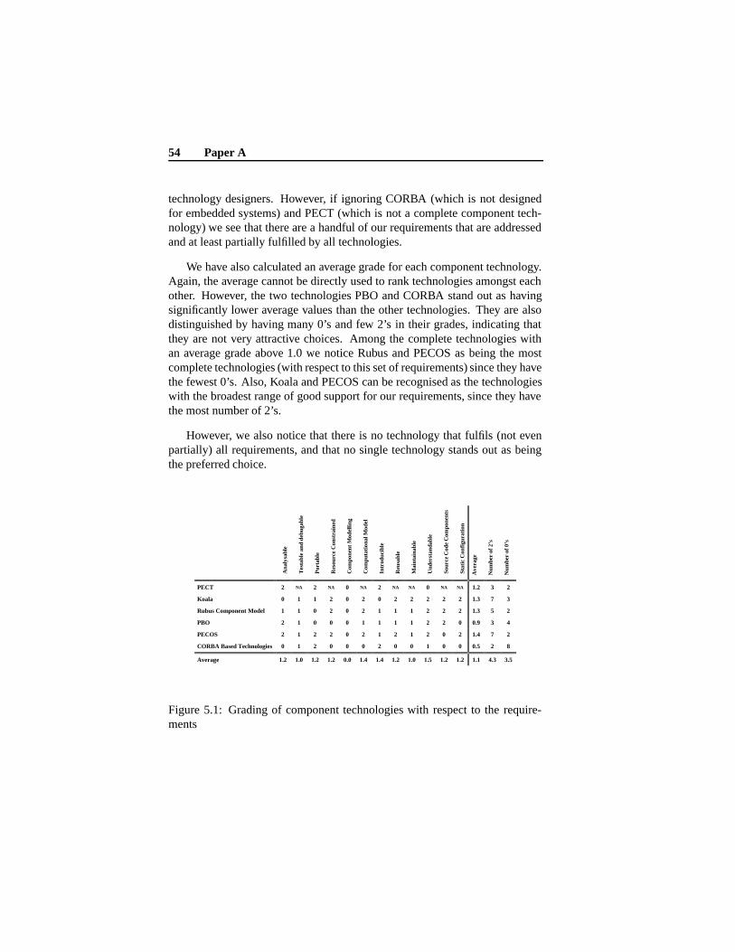
54 Paper A
technology designers. However, if ignoring CORBA (which is not designedfor embedded systems) and PECT (which is not a complete component tech-nology) we see that there are a handful of our requirements that are addressedand at least partially fulfilled by all technologies.
We have also calculated an average grade for each component technology.Again, the average cannot be directly used to rank technologies amongst eachother. However, the two technologies PBO and CORBA stand out as havingsignificantly lower average values than the other technologies. They are alsodistinguished by having many 0’s and few 2’s in their grades, indicating thatthey are not very attractive choices. Among the complete technologies withan average grade above 1.0 we notice Rubus and PECOS as being the mostcomplete technologies (with respect to this set of requirements) since they havethe fewest 0’s. Also, Koala and PECOS can be recognised as the technologieswith the broadest range of good support for our requirements, since they havethe most number of 2’s.
However, we also notice that there is no technology that fulfils (not evenpartially) all requirements, and that no single technology stands out as beingthe preferred choice.
Ana
lysa
ble
Tes
tabl
e an
d de
buga
ble
Por
tabl
e
Res
ourc
e C
onst
rain
ed
Com
pone
nt M
odel
ling
Com
puta
tion
al M
odel
Int
rodu
cibl
e
Reu
sabl
e
Mai
ntai
nabl
e
Und
erst
anda
ble
Sou
rce
Cod
e C
ompo
nent
s
Sta
tic
Con
figu
rati
on
Ave
rage
Num
ber
of 2
’s
Num
ber
of 0
’s
PECT 2 NA 2 NA 0 NA 2 NA NA 0 NA NA 1.2 3 2
Koala 0 1 1 2 0 2 0 2 2 2 2 2 1.3 7 3
Rubus Component Model 1 1 0 2 0 2 1 1 1 2 2 2 1.3 5 2
PBO 2 1 0 0 0 1 1 1 1 2 2 0 0.9 3 4
PECOS 2 1 2 2 0 2 1 2 1 2 0 2 1.4 7 2
CORBA Based Technologies 0 1 2 0 0 0 2 0 0 1 0 0 0.5 2 8
Average 1.2 1.0 1.2 1.2 0.0 1.4 1.4 1.2 1.0 1.5 1.2 1.2 1.1 4.3 3.5
Figure 5.1: Grading of component technologies with respect to the require-ments

5.5 Conclusion 55
5.5 Conclusion
In this paper we have compared some existing component technologies for em-bedded systems with respect to industrial requirements. The requirements havebeen collected from industrial actors within the business segment of heavy ve-hicles. The software systems developed in this segment can be characterisedas resource constrained, safety critical, embedded, distributed, real-time, con-trol systems. Our findings should be applicable to software developers whosesystems have similar characteristics.
We have noticed that, for a component technology to be fully accepted byindustry, the whole systems development context needs to be considered. Itis not only the technical properties, such as modelling, computation model,and openness, that needs to be addressed, but also development requirementslike maintainability, reusability, and to which extent it is possible to graduallyintroduce the technology. It is important to keep in mind that a componenttechnology alone cannot be expected to solve all these issues; however a tech-nology can have more or less support for handing the issues.
The result of the investigation is that there is no component technologyavailable that fulfil all the requirements. Further, no single component tech-nology stands out as being the obvious best match for the requirements. Eachtechnology has its own pros and cons. It is interesting to see that most re-quirements are fulfilled by one or more techniques, which implies that goodsolutions to these requirements exist.
The question, however, is whether it is possible to combine solutions fromdifferent technologies in order to achieve a technology that fulfils all listedrequirements? Our next step is to assess to what extent existing technolo-gies can be adapted in order to fulfil the requirements, or whether selectedparts of existing technologies can be reused if a new component technologyneeds to be developed. Examples of parts that could be reused are file andmessage formats, interface description languages, or middleware specifica-tions/implementations. Further, for a new/modified technology to be acceptedit is likely that it have to be compliant to one (or even more than one) existingtechnology. Hence, we will select one of the technologies and try to make assmall changes as possible to that technology.
Bibliography
Bibliography
[1] A. Möller, J. Fröberg, and M. Nolin. Industrial Requirements on Com-ponent Technologies for Embedded Systems. In Proceedings of the 7thInternational Symposium on Component-Based Software Engineering.2004 Proceedings Series: Lecture Notes in Computer Science, Vol. 3054,May 2004.
[2] I. Crnkovic and M. Larsson. Building Reliable Component-Based Soft-ware Systems. Artech House publisher, 2002. ISBN 1-58053-327-2.
[3] B. Selic and J. Rumbaugh. Using UML for modelling complex real-timesystems, 1998. Rational Software Corporation.
[4] Object Management Group. UML 2.0 Superstructure Specification, TheOMG Final Adopted Specification, 2003. http://www.omg.com/uml/.
[5] M. Shaw and D. Garlan. Software Architecture: Perspectives on anEmerging Discipline. Prentice Hall; 1 edition, 1996. ISBN 0-131-82957-2.
[6] D. Garlan, R. Allen, and J. Ockerbloom. Architectural mismatch or whyit’s hard to build systems out of existing parts. In Proceedings of the Sev-enteenth International Conference on Software Engineering, April 1995.
[7] Microsoft Component Technologies. COM/DCOM/.NET. http://www.-microsoft.com.
[8] R. Monson-Haefel. Enterprise JavaBeans, Third Edition. O’Reilly &Assiciates, Inc., 2001. ISBN: 0-596-00226-2.
[9] K. C. Wallnau. Volume III: A Component Technology for PredictableAssembly from Certifiable Components. Technical report, Software En-gineering Institute, Carnegie Mellon University, April 2003.
56
Bibliography 57
[10] R. van Ommering et al. The Koala Component Model for ConsumerElectronics Software. IEEE Computer, 33(3):78–85, March 2000.
[11] P. Clements and L. Northrop. Software Product Lines: Practices andPatterns. Addison-Wesley, 2001. ISBN 0-201-70332-7.
[12] K.L. Lundbäck and J. Lundbäck and M. Lindberg. Component-BasedDevelopment of Dependable Real-Time Applications. Arcticus Systems:http://www.arcticus.se (Last Accessed: 2005-01-18).
[13] K.L. Lundbäck. Rubus OS Reference Manual – General Concepts. Arcti-cus Systems: http://www.arcticus.se (Last Accessed: 2005-01-18).
[14] D.B. Stewart, R.A. Volpe, and P.K. Khosla. Design of DynamicallyReconfigurable Real-Time Software Using Port-Based Objects. IEEETransactions on Software Engineering, pages pages 759 – 776, December1997.
[15] P.K. Khosla et al. The Chimera II Real-Time Operating System for Ad-vanced Sensor-Based Control Applications. IEEE Transactions on Sys-tems, 1992. Man and Cybernetics.
[16] M. Winter, T. Genssler, et al. Components for Embedded Software – ThePECOS Apporach. In The Second International Workshop on Composi-tion Languages, in conjunction with the 16th ECOOP, June 2002.
[17] M. Sgroi. Quasi-Static Scheduling of Embedded Software Using Free-Choice Petri Nets. Technical report, University of California at Berkely,May 1998.
[18] O. Nierstrass, G. Arevalo, S. Ducasse, , R. Wuyts, A. Black, P. Müller,C. Zeidler, T. Genssler, and R. van den Born. A Component Model forField Devices. In Proceedings of the First International IFIP/ACM Work-ing Conference on Component Deployment, June 2002.
[19] R. Wuyts and S. Ducasse. Non-functional requirements in a componentmodel for embedded systems. In International Workshop on Specificationand Verification of Component-Based Systems, 2001. OPPSLA.
[20] Object Management Group. MinimumCORBA 1.0. http://-www.omg.org/technology/documents/formal/minimum_CORBA.htm(Last Accessed: 2005-01-17).
[21] D.C. Schmidt, D.L. Levine, and S. Mungee. The Design of the tao real-time object request broker. Computer Communications Journal, Summer1997.
[22] Object Management Group. CORBA Component Model. http://-www.omg.org/technology/documents/formal/components.htm (Last Ac-cessed: 2005-01-17).
Chapter 6
Paper B:Quality Attribute Support ina Component Technology forVehicular Software
Mikael Åkerholm, Johan Fredriksson, Kristian Sandström, and Ivica CrnkovicIn Fourth Conference on Software Engineering Research and Practice in Swe-den, Linköping, Sweden, October 2004
59
Abstract
The electronics in vehicles represents a class of systems where quality at-tributes, such as safety, reliability, and resource usage, leaven all through de-velopment. Vehicular manufacturers are interested in developing their softwareusing a component based approach, supported by a component technology, butcommercial component technologies are too resource demanding, complex andunpredictable. In this paper we provide a vehicular domain specific classifica-tion of the importance of different quality attributes for software, and a discus-sion of how they could be facilitated by a component technology. The resultscan be used as guidance and evaluation for research aiming at developing com-ponent technologies suitable for vehicular systems.
6.1 Introduction 61
6.1 Introduction
Component-based development (CBD) is of great interest to the software en-gineering community and has achieved considerable success in many engi-neering domains. CBD has been extensively used for several years in desktopenvironments, office applications, e-business and in general Internet- and web-based distributed applications. In many other domains, for example dependablesystems, CBD is utilized to a lesser degree for a number of different reasons.An important reason is the inability of component-based technologies to dealwith quality attributes as required in these domains. To identify the feasibilityof the CBD approach, the main concerns of the particular domain must be iden-tified along with how the CBD approach addresses these concerns and what isits ability to provide support for solutions related to these concerns are.
There is currently a lot of research on predicting and maintaining differentquality attributes within the Component Based Software Engineering (CBSE)community, (also called non-functional properties, extra-functional properties,and illities), [1, 2, 3, 4, 5]. Many of the quality attributes are conflicting andcannot be fully supported at the same time [6, 7]. Thus, it is important for ap-plication and system developers to be able to prioritize among different qualityattributes when resolving conflicts.
We provide a domain specific classification of the importance of qualityattributes for software in vehicles, and discuss how the attributes could be fa-cilitated by a component technology. The discussion contribute with a generaldescription of the desired quality attribute support in a component technologysuitable for the vehicle domain and it indicates which quality attributes requireexplicit support. In addition, it discusses were in the technology the supportshould be implemented: inside or outside the components, in the componentframework, on the system architecture level, or if the quality attributes are us-age dependent. Quality attributes might be conflicting; e.g., it is commonlyunderstood that flexibility and predictability are conflicting. The ranking pro-vided by industrial partners gives domain specific guidance for how conflictsbetween quality attributes should be resolved. The results also enable valida-tion and guidance for future work regarding quality attribute support in com-ponent technologies for software in vehicular systems. This guideline can beused to verify that the right qualities are addressed in the development processand that conflicting interdependent quality attributes are resolved according tothe domain specific priorities.
The starting point of this work is a list of quality attributes ranked accord-ing to their importance for vehicular systems. The list is provided through a
62 Paper B
set of interviews and discussions with experts from different companies in thevehicular domain. The results of the ranking from the vehicular companies arecombined with the classification of how to support different quality attributesprovided in [8]. The result is an abstract description of where, which, and howdifferent quality attributes should be supported by a component technology tai-lored for the vehicular industry.
A component technology as defined in [9] is a technology that can be usedfor building component based software applications. It implements a compo-nent model defining the set of component types, their interfaces, and, addition-ally, a specification of the allowable patterns of interaction among componenttypes. A component framework is also part of the component technology, itsrole can be compared to the role of an operating system, and it provides a va-riety of deployment and run-time services to support the component model.Specialized component technologies used in different domains of embeddedsystems have recently been developed, e.g., [10, 11]. There are also a numberof such component technologies under development in the research commu-nity, e.g., [12, 13, 14]. The existence of different component technologies canbe motivated by their support for different quality attributes, although they fol-low the same CBSE basic principles. It has been shown that companies devel-oping embedded systems in general consider different non functional qualityattributes far more important than efficiency in software development, whichexplains the specialization of component technologies [12].
The outline of the remaining part of the paper is as follows. Section 2 de-scribes the conducted research method, and section 3 the results. Section 4 isa discussion of the implications of the results, regarding the support for qual-ity attributes in a domain specific component technology. Section 5 discussesfuture work, and finally the section 6 concludes the paper.
6.2 Method
The research method is divided into three ordered steps:
1. During the first step a list of relevant quality attributes were gathered;
2. In the next step technical representatives from a number of vehicularcompanies placed priorities on each of the attributes in the list reflectingtheir companies view respectively;
3. Finally a synthesis step was performed, resulting in a description of the

6.2 Method 63
desired quality attribute support in a component technology for vehicularsystems.
The list of quality attributes have been collected from different literaturetrying to cover qualities of software that interest vehicular manufactures. Inorder to reduce a rather long list, attributes with clear similarities in their def-initions have been grouped in more generic types of properties, e.g., portabil-ity and scalability are considered covered by maintainability. Although suchgrouping could fade the specific characteristics of a particular attribute, it putfocus on the main concerns. In the ISO 9126 standard [15], 6 quality attributes(functionality, reliability, usability, efficiency, maintainability, and portability)are defined for evaluation of software quality. However, the standard has notbeen adopted fully in this work; it is considered too brief and does not cover at-tributes important for embedded systems (e.g., safety, and predictability). Fur-thermore, concepts that sometimes are mixed with quality attributes (for ex-ample fault tolerance) are not classified as quality attributes, rather as methodsto achieve qualities (as for example safety). Finally, functionality is of courseone of the most important quality attributes of a product, indicating how wellit satisfies stated or implied needs. However, we focus on quality attributes be-yond functionality often called extra-functional or non-functional properties.The resulting list of quality attributes is presented below.
Extendibility the ease with which a system or component can be modified toincrease its storage or functional capacity.
Maintainability the ease with which a software system or component can bemodified to correct faults, improve performance, or other attributes, oradapt to a changed environment.
Usability the ease with which a user can learn to operate, prepare inputs for,and interpret outputs from a system or component.
Predictability to which extent different run-time attributes can be predictedduring design time.
Security the ability of a system to manage, protect, and distribute sensitiveinformation.
Safety a measure of the absence of unsafe software conditions. The absenceof catastrophic consequences to the environment.
Reliability the ability of a system or component to perform its required func-tions under stated conditions for a specified period of time.
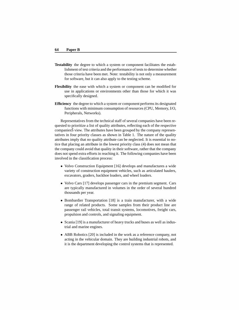
64 Paper B
Testability the degree to which a system or component facilitates the estab-lishment of test criteria and the performance of tests to determine whetherthose criteria have been met. Note: testability is not only a measurementfor software, but it can also apply to the testing scheme.
Flexibility the ease with which a system or component can be modified foruse in applications or environments other than those for which it wasspecifically designed.
Efficiency the degree to which a system or component performs its designatedfunctions with minimum consumption of resources (CPU, Memory, I/O,Peripherals, Networks).
Representatives from the technical staff of several companies have been re-quested to prioritize a list of quality attributes, reflecting each of the respectivecompaniesŠ view. The attributes have been grouped by the company represen-tatives in four priority classes as shown in Table 1. The nature of the qualityattributes imply that no quality attribute can be neglected. It is essential to no-tice that placing an attribute in the lowest priority class (4) does not mean thatthe company could avoid that quality in their software, rather that the companydoes not spend extra efforts in reaching it. The following companies have beeninvolved in the classification process:
• Volvo Construction Equipment [16] develops and manufactures a widevariety of construction equipment vehicles, such as articulated haulers,excavators, graders, backhoe loaders, and wheel loaders.
• Volvo Cars [17] develops passenger cars in the premium segment. Carsare typically manufactured in volumes in the order of several hundredthousands per year.
• Bombardier Transportation [18] is a train manufacturer, with a widerange of related products. Some samples from their product line arepassenger rail vehicles, total transit systems, locomotives, freight cars,propulsion and controls, and signaling equipment.
• Scania [19] is a manufacturer of heavy trucks and buses as well as indus-trial and marine engines.
• ABB Robotics [20] is included in the work as a reference company, notacting in the vehicular domain. They are building industrial robots, andit is the department developing the control systems that is represented.
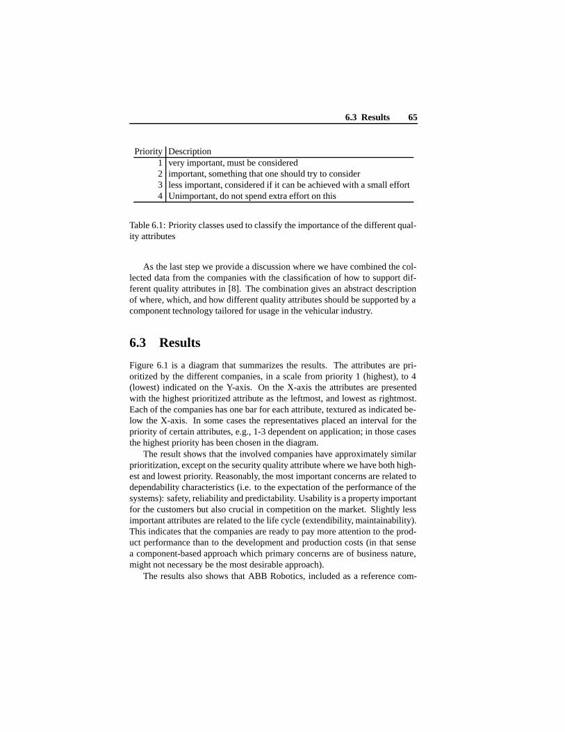
6.3 Results 65
Priority Description1 very important, must be considered2 important, something that one should try to consider3 less important, considered if it can be achieved with a small effort4 Unimportant, do not spend extra effort on this
Table 6.1: Priority classes used to classify the importance of the different qual-ity attributes
As the last step we provide a discussion where we have combined the col-lected data from the companies with the classification of how to support dif-ferent quality attributes in [8]. The combination gives an abstract descriptionof where, which, and how different quality attributes should be supported by acomponent technology tailored for usage in the vehicular industry.
6.3 Results
Figure 6.1 is a diagram that summarizes the results. The attributes are pri-oritized by the different companies, in a scale from priority 1 (highest), to 4(lowest) indicated on the Y-axis. On the X-axis the attributes are presentedwith the highest prioritized attribute as the leftmost, and lowest as rightmost.Each of the companies has one bar for each attribute, textured as indicated be-low the X-axis. In some cases the representatives placed an interval for thepriority of certain attributes, e.g., 1-3 dependent on application; in those casesthe highest priority has been chosen in the diagram.
The result shows that the involved companies have approximately similarprioritization, except on the security quality attribute where we have both high-est and lowest priority. Reasonably, the most important concerns are related todependability characteristics (i.e. to the expectation of the performance of thesystems): safety, reliability and predictability. Usability is a property importantfor the customers but also crucial in competition on the market. Slightly lessimportant attributes are related to the life cycle (extendibility, maintainability).This indicates that the companies are ready to pay more attention to the prod-uct performance than to the development and production costs (in that sensea component-based approach which primary concerns are of business nature,might not necessary be the most desirable approach).
The results also shows that ABB Robotics, included as a reference com-

66 Paper B
1
2
3
4
5
Safety
Reliab
ility
Predict
ability
Useabilty
Extenda
bility
Maintaina
bility
Efficie
ncy
Testabilit
y
Securit
y
Flexibilit
y
VolvoCE Bombardier Transportation
Volvo Cars Scania
ABB Robotics
Prio
rity
Figure 6.1: the results. Y-axis: priority of quality attributes in a scale 1 (high-est), to 4 (lowest). X-axis: the attributes, with the highest prioritized attributeas the leftmost, and lowest as rightmost. Each of the companies has one bar foreach attribute, textured as indicated below the X-axis.
pany outside the vehicular domain has also approximately the same opinion. Itis not possible to distinguish ABB Robotics from any of the vehicular compa-nies from a quality attribute perspective. These companies might use the samecomponent technology with respect to quality attribute support; thus the resultsin the investigation indicate that the priority among quality attributes scale to abroader scope of embedded computer control systems.
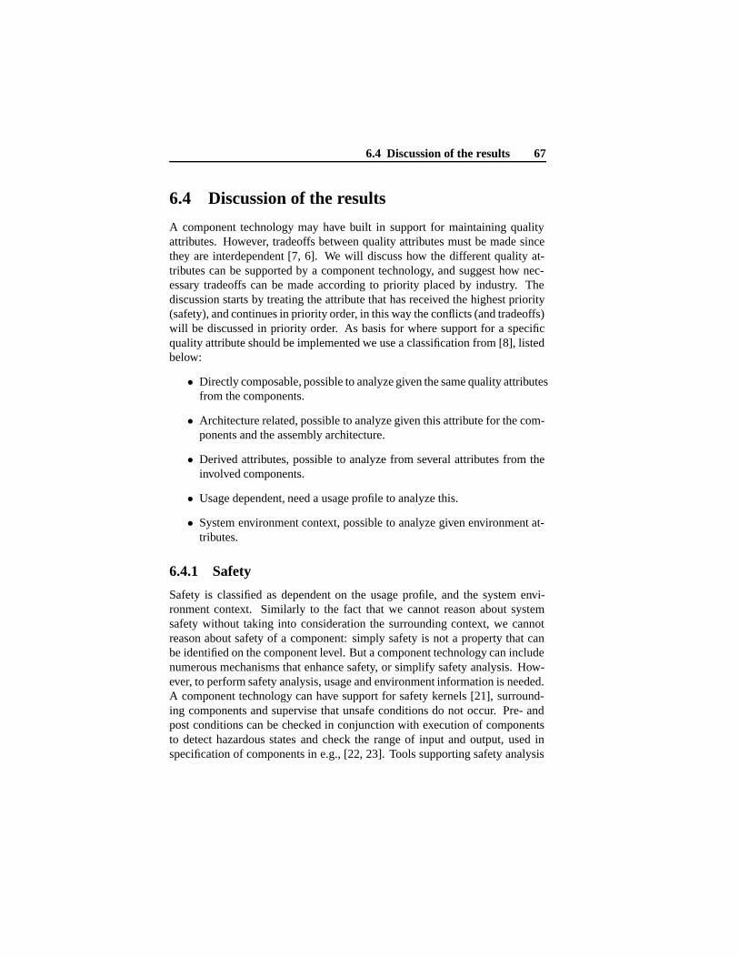
6.4 Discussion of the results 67
6.4 Discussion of the results
A component technology may have built in support for maintaining qualityattributes. However, tradeoffs between quality attributes must be made sincethey are interdependent [7, 6]. We will discuss how the different quality at-tributes can be supported by a component technology, and suggest how nec-essary tradeoffs can be made according to priority placed by industry. Thediscussion starts by treating the attribute that has received the highest priority(safety), and continues in priority order, in this way the conflicts (and tradeoffs)will be discussed in priority order. As basis for where support for a specificquality attribute should be implemented we use a classification from [8], listedbelow:
• Directly composable, possible to analyze given the same quality attributesfrom the components.
• Architecture related, possible to analyze given this attribute for the com-ponents and the assembly architecture.
• Derived attributes, possible to analyze from several attributes from theinvolved components.
• Usage dependent, need a usage profile to analyze this.
• System environment context, possible to analyze given environment at-tributes.
6.4.1 Safety
Safety is classified as dependent on the usage profile, and the system envi-ronment context. Similarly to the fact that we cannot reason about systemsafety without taking into consideration the surrounding context, we cannotreason about safety of a component: simply safety is not a property that canbe identified on the component level. But a component technology can includenumerous mechanisms that enhance safety, or simplify safety analysis. How-ever, to perform safety analysis, usage and environment information is needed.A component technology can have support for safety kernels [21], surround-ing components and supervise that unsafe conditions do not occur. Pre- andpost conditions can be checked in conjunction with execution of componentsto detect hazardous states and check the range of input and output, used inspecification of components in e.g., [22, 23]. Tools supporting safety analysis
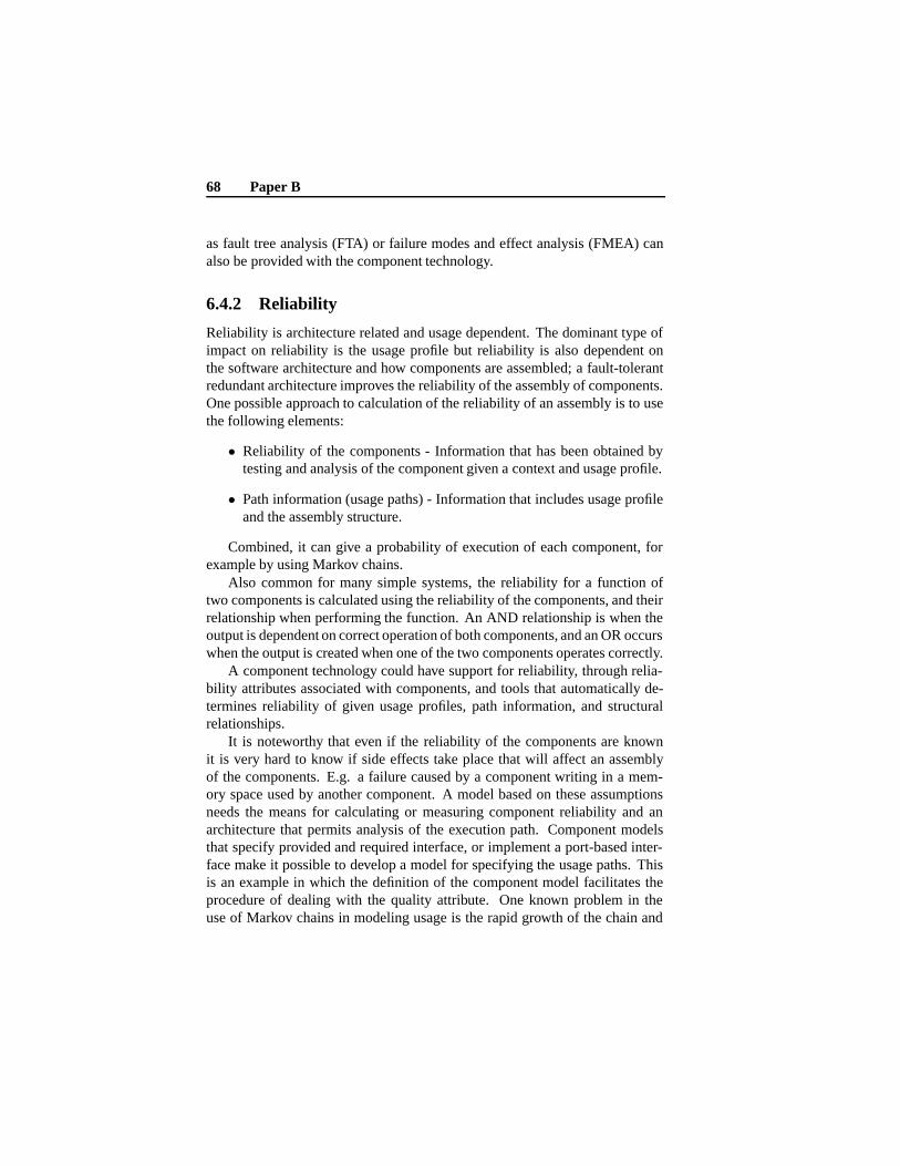
68 Paper B
as fault tree analysis (FTA) or failure modes and effect analysis (FMEA) canalso be provided with the component technology.
6.4.2 Reliability
Reliability is architecture related and usage dependent. The dominant type ofimpact on reliability is the usage profile but reliability is also dependent onthe software architecture and how components are assembled; a fault-tolerantredundant architecture improves the reliability of the assembly of components.One possible approach to calculation of the reliability of an assembly is to usethe following elements:
• Reliability of the components - Information that has been obtained bytesting and analysis of the component given a context and usage profile.
• Path information (usage paths) - Information that includes usage profileand the assembly structure.
Combined, it can give a probability of execution of each component, forexample by using Markov chains.
Also common for many simple systems, the reliability for a function oftwo components is calculated using the reliability of the components, and theirrelationship when performing the function. An AND relationship is when theoutput is dependent on correct operation of both components, and an OR occurswhen the output is created when one of the two components operates correctly.
A component technology could have support for reliability, through relia-bility attributes associated with components, and tools that automatically de-termines reliability of given usage profiles, path information, and structuralrelationships.
It is noteworthy that even if the reliability of the components are knownit is very hard to know if side effects take place that will affect an assemblyof the components. E.g. a failure caused by a component writing in a mem-ory space used by another component. A model based on these assumptionsneeds the means for calculating or measuring component reliability and anarchitecture that permits analysis of the execution path. Component modelsthat specify provided and required interface, or implement a port-based inter-face make it possible to develop a model for specifying the usage paths. Thisis an example in which the definition of the component model facilitates theprocedure of dealing with the quality attribute. One known problem in theuse of Markov chains in modeling usage is the rapid growth of the chain and

6.4 Discussion of the results 69
complexity [24]. The problem can be solved because the reliability permitsa hierarchical approach. The system reliability can be analyzed by (re)usingthe reliability information of the assemblies and components (which can bederived or measured).
Reliability and Safety are not conflicting attributes. Reliability enhancessafety, high reliability increases confidence that the system does what it is in-tended to and nothing else that might lead to unsafe conditions.
6.4.3 Predictability
We focus on predictability of the particular run-time attributes temporal be-haviour, memory consumption, and functional behaviour. Predictability isdirectly composable and architecture dependent. Prediction of temporal be-haviour is well explored in research within the real-time community. Depend-ing on the run-time systems scheduling strategy, the shared resource access andexecution demands of the scheduled entities, suitable prediction theories can bechosen, e.g., for fixed priority systems that are most common within industry[25, 26]. The choice of scheduling strategy is also a problem that has beenaddressed [27]. Static scheduled systems are more straightforward to predictthan event driven systems that on the other hand are more flexible. Memoryconsumption can be predicted, given the memory consumption for the differentcomponents in the system [28]. However, two different types of memory con-sumption can be identified: static and dynamic. Static memory consumption isthe most straightforward to predict, since it is a simple summation of the mem-ory requirements of the included components. Dynamic memory consumptioncan be more complex, since it might be dependent on usage input, and therebybe usage dependent.
Predictability is not in conflict with the higher prioritized attributes relia-bility and safety. Predictable behaviour enhances safety and reliability, e.g.,unpredictable behaviour cannot be safe because it is impossible to be sure thatcertain actions will not take place.
6.4.4 Usability
Usability is a rather complex quality attribute, which is derived from severalother attributes; it is architecture related and usage dependent. Usability is notdirectly related to selection of component technology. Software in embeddedsystems (the most common and important type of software in vehicular sys-tems) is usually not visible and does not directly interact with the user. How-

70 Paper B
ever, more and more human-machine interaction is implemented in underlyingsoftware. In many cases we can see how the flexibility of software is abused- there are many devices (for example in infotainment) with numerous buttonsand flashing screens that significantly decrease the level of usability. Use ofa component technology may however indirectly contribute to usability - bybuilding standard (user-interface) components, and by their use in different ap-plications and products, the same style, type of interaction, functionality andsimilar are repeated. In this way they become recognisable and consequentlyeasier to use.
Usability as discussed above is not in obvious conflict with any of thehigher prioritized quality attributes.
6.4.5 Extendibility
Extendibility is directly composable and architecture related. It can be sup-ported by the component technology through absence of restrictions in size re-lated parameters, e.g., memory size, code size, and interface size. Extendibilityis one of the main concerns of a component technology and it is explicitly sup-ported U either by ability of adding or extending interfaces or by providing aframework that supports extendibility by easy updating of the system with newor modified components.
Extendibility is not in direct conflict with any of the higher prioritized at-tributes. However, conflicts may arise due to current methods used for analysisand design of safety critical systems real-time systems, the methods often re-sults in systems that are hard to extend [29]. Predictability in turn enhancesextendibility, since it makes predications of the impact of an extension possi-ble.
6.4.6 Maintainability
Maintainability is directly composable and architecture related. A componenttechnology supports maintainability through configuration management tools,clear architectures, and possibilities to predict impacts of applied changes.
Maintainability is not in obvious conflict with any of the higher priori-tized attributes. But as for extendibility, current state of practice for achievingsafety, dependability and predictability results in systems that often are hardto maintain [29]. Maintainability increases usability, while good predictabilityin turn increases maintainability since impacts of maintenance efforts can bepredicted.
6.4 Discussion of the results 71
6.4.7 Efficiency
Efficiency is directly composable and architecture related. Efficiency is af-fected by the component technology, mainly through resource usage by therun-time system but also by interaction mechanisms. Good efficiency is equalto low memory, processor, and communication medium usage.
In the requirements for a software application it might often be the casethat a certain amount of efficiency is a basic requirement, because of limitedhardware resources, control performance, or user experienced responsiveness.In such cases the certain metrics must be achieved, but efficiency is poten-tially in conflict with many higher prioritized quality attributes. Safety relatedrun-time mechanisms as safety kernels, and checking pre- and post conditionsconsume extra resources and are thus in conflict with efficiency. Reliability isoften increased by redundancy, by definition conflicting with efficiency. Meth-ods used for guaranteeing real-time behaviour are pessimistic and result in lowutilization bounds [30], although it is a widely addressed research problem andimprovements exist, e.g., [31, 32].
6.4.8 Testability
Testability is directly composable and architecture related. A general rule fortestability is that simple systems are easier to test than complex systems; how-ever, what engineers build is not directly related to the technology itself. Di-rect methods to increase testability provided by a component technology canbe built in self tests in components, monitoring support in the run-time system,simulation environments, high and low level debugging information [33].
Testability is not in conflict with any of the higher prioritized quality at-tributes. On the contrary, it supports several other attributes, e.g., safety isincreased by testing that certain conditions cannot occur, predictions are con-firmed by testing, maintainability is increased if it is possible to test the impactof a change. However, efficiency tradeoffs might have to be done to enabletesting. A problem with many common testing methods is the probe effect in-troduced by software probes used for observing the system [34]. If the probesused during testing are removed in the final product, it is not the same systemthat is delivered as the one tested. To avoid this problem, designers can chooseto leave the probes in the final product and sacrifice efficiency, or possibly usesome form of non-intrusive hardware probing methods, e.g., [35]. Reliabilityimplemented by fault tolerance decrease testability, since faults may becomehidden and complicate detection by testing.
72 Paper B
6.4.9 Security
Security is usage dependent and dependent on the environment context, mean-ing that it is not directly affected by the component technology. However,mechanisms increasing security can be built in a component technology, e.g.,encryption of all messages, authorization of devices that communicate on thebus.
Methods to increase security that can be built in a component technologyare often in conflict with higher prioritized quality attributes, e.g., encryption isin conflict with efficiency since it require more computing, and with testabilitysince it is harder to observe the system. Furthermore security has a low priority,and the methods to achieve it are not dependent on support from the componenttechnology. Hence, security can be implemented without support from thecomponent technology.
6.4.10 Flexibility
Flexibility is directly composable and architecture related. A component tech-nology can support flexibility through the components, their interactions, andarchitectural styles to compose systems. Methods increasing flexibility in acomponent technology can be, e.g., dynamic run-time scheduling of activitiesbased on events, run-time binding of resources, and component reconfigurationduring run-time.
Flexibility has received the lowest priority of all quality attributes, and isin conflict with many higher prioritized attributes, e.g., with safety since thenumber of different hazardous conditions increases, with testability since thenumber of test cases increases and it may not be possible at all to create arealistic run-time situation thus not to test the actual system either. On the otherhand flexibility increases maintainability, since a flexible system is easier tochange during maintenance. It is not possible to use completely static systemswith no flexibility at all when user interaction is involved, but regarding to thenumerous conflicts with higher prioritized quality attributes it should be keptto a minimum in component technologies for this domain.
6.4.11 Quality Attribute Support in a Component Technol-ogy for the Automotive Domain
Having presenting the basic characteristics of quality attributes related to com-ponent technologies, and identification of present conflicts, and suggestions on
6.4 Discussion of the results 73
how to resolve the conflict we give a brief description of the resulting sugges-tion of support for quality attributes in a component technology tailored forvehicular systems below:
Safety Safety cannot be fully supported by a component technology. How-ever, safety kernels surrounding components and support for definingpre- and post conditions are suggested.
Reliability Reliability is supported to a large extent by a component technol-ogy. We suggest reliability attributes associated with components, pathinformation including usage profile and assembly structure, and tools foranalysis. There should also be support for redundant components whennecessary.
Predictability Predictability is supported to a large extent. Associated to thecomponents, attributes such as execution time, and memory consump-tion can be specified. Tools for automated analysis can be provided withthe technology.
Usability Usability is not directly supported by a component technology.
Extendibility Extendibility is well supported. The interfaces should be easyto extend and it should be easy to add new components to an existing sys-tem. There should be no size related restrictions with respect to memory,code, and interface.
Maintainability Maintainability is well supported by a component technol-ogy. The support is provided through configuration management tools,and the fact that using well defined components gives a clear and main-tainable architecture.
Efficiency Efficiency is suggested to be supported to a fairly high level. Wesuggest support through small and efficient run-time systems, howevernot to the cost of suggested safety and reliability related run-time mech-anisms.
Testability Testability is supported to a large extent. The support is suggestedto be monitoring possibilities in the run-time system, simulation and de-bug possibilities.
Security Security is not directly supported.
Flexibility Flexibility is not directly supported.

74 Paper B
6.5 Future Work
We will continue with research towards enabling CBSE for automotive sys-tems. One part is to continue investigating the requirements on quality at-tributes from the domain, with our present and other industrial partners. An-other part is an analysis of particular component models to investigate theirabilities of supporting these quality attributes. A third part is to enable supportfor quality attributes in the component technologies we are developing as pro-totypes suitable for the domain AutoComp [36] and SaveComp [12], but wewill also asses to which extent other existing component technologies can beused in order to meet the industrial requirements.
6.6 Conclusions
We have presented a classification of the importance of quality attributes forsoftware made by some companies in the vehicular domain; the results showedthat the companies agreed upon the priority for most of the attributes. Themost important concerns showed to be related to dependability characteristics(safety, reliability and predictability). Usability received a fairly high prior-ity. Slightly less important attributes where those related to the life cycle (ex-tendibility, maintainability), while security and flexibility received the lowestpriority. We also included a company outside the domain in the investigation,it turned out that they also agreed upon the classification; it might be that theclassification scale to a broader scope of embedded systems.
Furthermore, we have discussed how the attributes could be facilitated bya component technology, and were in the technology the support should beimplemented: inside or outside the components, in the framework, or if thequality attributes are usage dependent. The discussion is concluded by a briefsuggestion of quality attribute support for a component technology.
Acknowledgements We would like to thank our industrial partners for theirtime, and the interest they have shown in discussing quality attributes. Thanksto Joakim Fröberg from Volvo CE, Jakob Axelsson from Volvo Cars, MattiasEkman from Bombardier Transportation, Ola Larses and Bo Neidenström fromScania, and Bertil Emertz from ABB Robotics.
Bibliography
[1] I. Crnkovic and M. Larsson. Classification of quality attributes for pre-dictability in component-based systems. In In DSN 2004 Workshop onArchitecting Dependable Systems, June 2004.
[2] G.A. Moreno, S.A. Hissam, and K.C. Wallnau. Statistical models forempirical component properties and assembly-level property predictions:Towards standard labeling. In Proceedings of 5th Workshop on compo-nent based software engineering, 2002.
[3] R.H. Reussner, H.W. Schmidt, and I. Poernomo. Reliability predictionfor component-based software architectures. Journal of Systems and Soft-ware, 66(3):241–252, 2003.
[4] H.W. Schmidt. Trustworthy components: Compositionality and predic-tion. Journal of Systems and Software, 65(3):212–225, 2003.
[5] J. Stafford and J. McGregor. Issues in the reliability of composed com-ponents. In 5th workshop on component based software engineering(CBSE5), 2002.
[6] D. Haggander, L. Lundberg, and J. Matton. Quality attribute conflicts -experiences from a large telecommunication application. In Proceedingsof the 7th IEEE International Conference on Engineering of ComplexComputer Systems, 2001.
[7] M. Barbacci, M. H. Klein, T. A. Longstaff, and C. B. Weinstock. Qual-ity attributes. Technical report, Software Engineering Institute, CarnegieMellon University, 1995.
[8] M. Larsson. Predicting Quality Attributes in Component-based SoftwareSystems. PhD thesis, Mälardalen University, March 2004.
75

76 Bibliography
[9] F. Bachmann, L. Bass, C. Buhman, S. Comella-Dorda, F. Long, J. Robert,R. Seacord, and K. Wallnau. Technical concepts of component-basedsoftware engineering, volume ii. Technical report, Software EngineeringInstitute, Carnegie-Mellon University, May 2000. CMU/SEI-2000-TR-008.
[10] O. Nierstrass, G. Arevalo, S. Ducasse, , R. Wuyts, A. Black, P. Müller,C. Zeidler, T. Genssler, and R. van den Born. A Component Model forField Devices. In Proceedings of the First International IFIP/ACM Work-ing Conference on Component Deployment, June 2002.
[11] R. van Ommering, F. van der Linden, and J. Kramer. The koala compo-nent model for consumer electronics software. In IEEE Computer, pages78–85. IEEE, March 2000.
[12] H. Hansson, M. Åkerholm, I. Crnkovic, and M. Törngren. SaveCCM -a Component Model for Safety-Critical Real-Time Systems. In Proceed-ings of 30th Euromicro Conference, Special Session Component Modelsfor Dependable Systems, September 2004.
[13] M. de Jonge, J. Muskens, and M. Chaudron. Scenario-based predictionof run-time resource consumption in component-based software systems.In Proceedings of the 6th ICSE Workshop on Component-Based SoftwareEngineering (CBSE6), May 2003.
[14] K. C. Wallnau. Volume III: A Component Technology for PredictableAssembly from Certifiable Components. Technical report, Software En-gineering Institute, Carnegie Mellon University, April 2003.
[15] ISO/IEC. Software engineering – Product quality – Part 1: Qualitymodel, ISO/IEC 9126-1, 2001.
[16] Volvo construction equipment homepage. http://www.volvo.com/-constructionequipment.
[17] Volvo cars homepage. http://www.volvocars.com/.
[18] Bombardier transportation homepage. http://www.transportation.-bombardier.com/.
[19] Scania homepage. http://www.scania.com/.
[20] Abb robotics homepage. http://www.abb.com/robotics.
Bibliography 77
[21] J. Rushby. Kernel for safety, in safe and secure computing systems. Tech-nical report, Blackwell Scientific Publications, Londres, 1989.
[22] J. Chessman and J. Daniels. UML Componets - A simple process forspecifying Component-Based Software. Reading, MA: Addison-Wesley,2000.
[23] D. D’Souza and A.C. Wills. Objects, Components and Frameworks: TheCatalysis Approach. Reading, MA: Addison-Wesley, 1998.
[24] H.W. Schmidt and R.H. Reussner. Parameterized Contracts and AdapterSynthesis. In Proceedings of the 5th ICSE Workshop on Component-Based Software Engineering, May 2001.
[25] N. C. Audsley, A. Burns, R. I. Davis, K. W. Tindell, , and A. J. Wellings.Fixed priority pre-emptive scheduling: An historical perspective. Real-Time Systems Journal, 8(2/3):173–198, 1995.
[26] O. Redell and M. Törngren. Calculating exact worst case response timesfor static priority scheduled tasks with offsets and jitter. In Proc. EighthIEEE Real-Time and Embedded Tech-nology and Applications Sympo-sium. IEEE, September 2002.
[27] J. Xu and D. L. Parnas. On Satisfying Timing Constraints in Hard-Real-Time Systems. IEEE Transactions on Software Engineerin, 19(1):70–84,1993.
[28] A.V. Fioukov, E.M. Eskenazi, D.K. Hammer, and M. Chaudron. Evalua-tion of Static Properties for Component-Based Architetures. In Proceed-ings of 28th Euromicro Conference, September 2002.
[29] A. Burns and J. A. McDermid. Real-time safety-critical systems: analysisand synthesis. Software Engineering Journal, 9(6):267–281, Nov 1994.
[30] C. L. Liu and J. W. Layland. Scheduling Algorithms for Multiprogram-ming in hard-real-time environment. Journal of the Association for Com-puting Machinery (ACM), 20(1):46–61, 1973.
[31] T. F. Abdelzaher, V. Sharma, and C. Lu. A utilization bound for aperiodictasks and priority driven scheduling. IEEE Transactions on Computers,53(3):334–350, Mar 2004.
[32] C. Deji, A. K. Mok, and K. Tei-Wei. Utilization bound revisited. IEEETransactions on Computers, 52(3):351–361, March 2003.
[33] H. Thane. Testing and Debugging of Distributed Real-Time Systems. PhDthesis, Royal Institute of Technology, May 2000.
[34] J. Gait. A probe effect in concurrent programs. Software Practise andExperience, 16(3), March 1986.
[35] M. El Shobaki and L. Lindh. A hardware and software monitor for high-level system-on-chip verification. In Proceedings of the IEEE Interna-tional Symposium on Quality Electronic Design, March 2001.
[36] K. Sandström, J. Fredriksson, and M. Åkerholm. Introducing a Com-ponent Technology for Safety Critical Embedded Real-Time Systems.In Proceedings of th 7th International Symposium on Component-BasedSoftware Engineering (CBSE7), May 2004.
Chapter 7
Paper C:SaveCCM a ComponentModel for Safety-CriticalReal-Time Systems
Hans Hansson, Mikael Åkerholm, Ivica Crnkovic, and Martin TörngrenIn Euromicro Conference, Special Session Component Models for DependableSystems, Rennes, France, September 2004
79
Abstract
Component-based development has proven effective in many engineering do-mains, and several general component technologies are available. Most ofthese are focused on providing an efficient software-engineering process. How-ever, for the majority of embedded systems, run-time efficiency and predictionof system behaviour are as important as process efficiency. This calls for spe-cialized technologies. There is even a need for further specialized technologiesadapted to different types of embedded systems, due to the heterogeneity of thedomain and the close relation between the software and the often very applica-tion specific system.
This paper presents the SaveCCM component model, intended for embed-ded control applications in vehicular systems. SaveCCM is a simple model inwhich flexibility is limited to facilitate analysis of real-time and dependability.We present and motivate the model, and provide examples of its use.
7.1 Introduction 81
7.1 Introduction
Component-based development (CBD) is of great interest to the software engi-neering community and has achieved considerable success in many engineer-ing domains. Some of the main advantages of CBD are reusability, higher ab-straction level and separation of the system development process from the com-ponent development process. CBD has been extensively used for several yearsin desktop environments, office applications, e-business and in Internet- andweb-based distributed applications. The component technologies used in thesedomains originates from object-oriented (OO) techniques. The basic princi-ples of the OO approach, such as encapsulation and class specification, havebeen further extended; the importance of component interfaces has increased:a component interface is treated as a component specification and the compo-nent implementation is treated as a black box. A component interface is alsothe means of integrating the components in an assembly. Component tech-nologies include the support of component deployment into a system throughthe component interface. On the other hand, the management of components’quality attributes has not been supported by these technologies. In the domainsin which these technologies are widely used, the quality attributes have notbeen of primary interest and have not been explicitly addressed; they have in-stead been treated separately from the applied component-based technologies.In many other domains, for example embedded systems, CBD is utilized toa lesser degree for a number of different reasons, although the approach is asattractive here as in other domains. One reason for the limited use of CBD inthe embedded systems domain is the difficulty to transfer existing technologiesto this domain, due to the difference in system constraints. Another importantreason is the inability of component-based technologies to deal with qualityattributes as required in these domains. For embedded systems, a number ofquality attributes are at least as important as the provided functionality, andthe development efforts related to them are most often greater than the effortsrelated to the implementation of particular functions. For development of ve-hicular systems, CBD is an attractive approach, but due to specific require-ments of system properties such as real-time, reliability and safety, restrictedresource consumption (e.g., memory and CPU), general-purpose componentmodels cannot be used. Instead new component models that keep the mainprinciples of the CBD approach, but fulfil specific requirements of the domain,must be developed.
This paper discusses the component model SaveCCM, a part of SAVE-Comp, a component-based development framework being developed in the
82 Paper C
project SAVE (Component Based Design of Safety Critical Vehicular Sys-tems). The basic idea of SAVEComp is to by focusing on simplicity andanalysability of real-time and dependability quality attributes provide efficientsupport for designing and implementing embedded control applications for ve-hicular systems
The paper is organised as follows. Section 2 gives a short overview of dif-ferent component models used in embedded systems. Section 3 briefly presentsthe SAVE project, and Section 4 outlines the characteristics of the consideredapplication domain. In Section 5, our component model SaveCCM is pre-sented, including textual and graphical syntax, as well as a few illustrativeexamples. A larger and more complete example from the vehicular domain isprovided in Section 6, and in Section 7 we summarize and give an outline offuture work.
7.2 Related work
In addition to widely used component technologies, new component modelsappear in different application domains, both in industry and academia. Wewill refer to some of them: Koala and Rubus used in industry and the researchmodels PECT, PECOS and ROBOCOP.
The Koala component technology [1] is designed and used by Philips fordevelopment of software in consumer electronics. Koala has passive compo-nents that interact through a pipes-and-filters model, which is allocated to ac-tive threads. However, Koala does not support analysis of run-time properties.
The Robocop component model [2] is a variant of the Koala componentmodel. A Robocop component is a set of models, each of which provides aparticular type of information about the component. An example of such amodel is the non-functional model that includes modeling timeliness, reliabil-ity, memory use, etc. Robocop aims to cover all aspects of a component-baseddevelopment process for embedded systems.
The Rubus Component Model [3] is developed by Arcticus systems aimedfor small embedded systems. It is used by Volvo Construction Equipment. Thecomponent technology incorporates tools, e.g. a scheduler and a graphical toolfor application design, and it is tailored for resource constrained systems withreal-time requirements. In many aspects Rubus Component Model is similar toSaveCCM; actually some of the basic approaches from Rubus are included inSAVEComp. One difference is that SAVEComp is focused on multiple qualityattributes and independences of underlying operating system.
7.3 The SAVE project 83
PECT (Prediction-enabled Component Technology) from Software Engi-neering Institute at CMU [4, 5] focuses on quality attributes specification andmethods for prediction of quality attributes on system level from attributes ofcomponents. The component model enables description of some real-time at-tributes. Compared with SAVECom, PECT is a more general-purpose compo-nent technology and more complex.
PECOS (PErvasive COmponent Systems) [6], developed by ABB Corpo-rate Research Centre and academia, is designed for field devices, i.e. reactiveembedded systems that gathers and analyze data via sensors and react by con-trolling actuators, valves, motors etc. The focus is on non-functional propertiessuch as memory consumption and timeliness, which makes PECOS goals sim-ilar to SaveCCM.
These examples show that there are many similar component technologiesfor development of embedded systems. One could ask if it would not be moreefficient to use a single model. Experiences have shown that for many embed-ded system domains efficiency in run-time resources consumption and predic-tion of system behaviour are far more important than efficiency in the softwaredevelopment. This calls for specialization, not generalization. Another argu-ment for specialization is the typically very close relation between softwareand the system in which the software is embedded. Different platforms anddifferent system architectures require different solutions on the infrastructureand inter-operability level, which leads to different requirements for compo-nent models. Also the nature of embedded software limits the possibilities ofinteroperability between different systems. Despite the importance of perva-siveness, dynamic configurations of interoperation between systems, etc. thisis still not the main focus of vast majorities of embedded systems.
These are the reasons why different application domains call for differentcomponent models, which may follow the same basic principles of component-based software engineering, but may be different in implementations. With thatin mind we can strongly motivate a need for a component technology adjustedfor vehicular systems.
7.3 The SAVE project
The long term aim of the SAVE [7] project is to establish an engineering disci-pline for systematic development of component-based software for safety criti-cal embedded systems. SAVE is addressing the above challenge by developinga general technology for component-based development of safety-critical ve-
84 Paper C
hicular systems, including:
• Methodology and process for development of systems with components
• Component specification and composition, providing a component modelwhich includes the basic characteristics of safety-critical componentsand infrastructure supporting component collaboration.
• Techniques for analysis and verification of functional correctness, real-time behaviour, safety, and reliability.
• Run-time and configuration support, including support for assemblingcomponents into systems, run-time monitoring, and evaluation of alter-native configurations.
The main objective of SAVE is to develop SAVEComp - a component-based development (CBD) technology for safety-critical embedded real-timesystems (RTS). The primary focus is on designing systems with components,based on component and system models. The ambition is to develop a methodand infrastructure for CBD for safety-critical embedded RTS, corresponding toexisting general component technologies, such as COM and JavaBeans.
7.4 Application Characteristics
As mentioned above, the considered application domain is vehicular systems.Within that domain we are mainly considering the safety-critical sub-systemsresponsible for controlling the vehicle dynamics, including power-train, steer-ing, braking, etc.
The vehicular industry has a long tradition of building systems from com-ponents provided by different suppliers. In the past these components havebeen purely mechanical, but today many of the components include computersand software. The trend today is, on one hand, towards intelligent mechatron-ics light weight nodes, such as actuators including a microprocessor. On theother hand, there are trends towards more integrated and flexible architectures,where software components can be freely allocated to heavy weight computerunits (Electronic Control Units; ECUs). One reason for this is that the numberof ECUs is growing beyond control in a modern car (in the range of 100 intop of the line models). Letting SW from several suppliers, related to differentsub-systems, execute on the same ECU has several benefits, including reducednumber of ECUs, reduced cabling, reduced number of connection points (es-sential for system reliability), reduced weight, and reduced per-unit production

7.4 Application Characteristics 85
cost. The downside is an increased risk of interference between the differentsub-systems. Minimizing this risk and increasing efficiency and flexibility inthe design process is the main motivation for SAVEComp and other effortscurrently in progress (e.g. the EAST/EEA initiative [8]).
The safety-critical sub-systems we consider will in the foreseeable futurehave the following characteristics:
• Statically configured, i.e., the components used and their interconnec-tions will essentially be decided at design or configuration time. Hence,the binding will be static, as opposed to the dynamic binding used incurrent component technologies.
• It will be essential to satisfy and provide proof of satisfaction of not onlythe functional behaviour, but also of timing and dependability qualityattributes.
• The timing and dependability quality attributes will be strict, in the sensethat they will be specified in terms of absolute bounds that must be sat-isfied.
• There will be additional, less critical, less static components executingon the same ECUs as the critical ones. The focus of SAVE is howevernot on these.
• The systems will be resource constrained, in the sense that the per-unitcost is a main optimization criterion, i.e., the use of computer and com-puting resources should be kept at a minimum.
• Due to the product-line nature of the industry, reuse of architectures,components and quality assessments should be supported.
• The contractual aspect of system and component models will in manycases be important as a tool for communication and ensuring quality inthe integrator U supplier relation.
Looking more in detail at the timing quality attributes, SaveCCM should pro-vide sufficient machinery to express and reason about the following types oftiming attributes/requirements:
• End-to-end timing, i.e., it should be possible to determine (or guaran-tee) that the time from some event (e.g., sampling of a sensor value) tothe time of some other event (e.g., providing a new control signal to anactuator) stays within specified bounds.
86 Paper C
• Freshness of data, i.e., it should be possible to determine (or guarantee)that a datum has been generated no earlier than a specified bound beforeit is used by a specific component (e.g., that a sensor value has beensampled no earlier than 35ms before it is used by a specific component).
• Simultaneity, i.e., it should be possible to determine (or guarantee) thata set of data occur sufficiently close together in time (e.g., that the sam-pling of two sensors occur within 2ms).
• Jitter tolerances, i.e., it should be possible to determine (or guarantee)that the variation in latency between two events stay within specifiedbounds (e.g., that the variation in the time between subsequent (periodic)samplings of a sensor value stays within 2ms).
7.5 The SAVEComp Component Model
SaveCCM has its roots in previous models and design methods for embeddedreal-time systems, in particular Basement [9] and its extensions into the Rubus-methodology [10, 3]. SaveCCM, and its predecessors are designed specificallyfor the vehicular domain, which (in contrast with many of the current compo-nent technologies) implies that predictability and analysability are more im-portant than flexibility. Hence, the model should be as restrictive as possible,while still allowing the intended applications to be conveniently designed. It iswith this in mind we have designed SaveCCM.
7.5.1 Architectural Elements
SaveCCM consists of the following main elements:
Components which are basic units of encapsulated behaviour, that executesaccording to the execution model presented below.
Switches which provide facilities to dynamically change the component inter-connection structure (at configuration or run-time).
Assemblies which provide means to form aggregate components from sets ofinterconnected components and switches.
Run-time framework which provides a set of services, such as communica-tion between components. Component execution and control of sensorsand actuators.
7.5 The SAVEComp Component Model 87
Both switches and assemblies can be considered to be special types of com-ponents. Due to the difference in semantics we will, however, treat them as sep-arate elements. Below, we will elaborate on these elements, their properties,and their attributes.
Functional interfaceThe functional interface of all architectural elements is defined in terms of a
set of associated ports, which are points of interaction between the element andits external environment. We distinguish between input- and output ports, andthere are two complementary aspects of ports: the data that can be transferredvia the port and the triggering of component executions. SaveCCM distinguishbetween these two aspects, and allow three types of ports: (1) data-only ports,(2) triggering-only ports, and (3) data and triggering ports.
An architectural element emits trigger signals and data at its output ports,and receives trigger signals and data at its input ports. Systems are built fromcomponents by connecting input ports to output ports. Ports can only be con-nected if their types match, i.e. identical data types are transferred and thetriggering coincides.
Data-only ports are one element buffers that can be read and written. Eachwrite will overwrite the previous value stored. Output and input ports are dis-tinct, in the sense that writing a datum to an output port does not mean that thedatum is immediately available at the input port connected to the output port.This is to allow transfer of data between ports over a network or any othermechanism that does not guarantee atomicity of the transfer.
Triggering-only ports are used for controlling the activation of components.A component may have several triggering ports. The component is triggeredwhen all input triggering ports are activated. Several output triggering portsmay be connected to a single input triggering port, providing an OR-semantics,in the sense that the input port is triggered if at least one of its connected outputports is activated. Note that the input triggering port is active from the time ofactivation (triggering) to the start of execution of the component. Activationscannot be cancelled, and activating an active port has no effect.
Data and triggering ports combine data-only and triggering-only ports inthe obvious way.
Execution ModelSince predictability and analyzability are of primary concern for the consid-
ered application domain, the SaveCCM execution model is rather restrictive.
88 Paper C
The basis is a control-flow (pipes and filter) paradigm in which executionsare triggered by clocks or external events, and where components have finite,possibly variable, execution time.
On a high level, a component is either waiting to be activated (triggered) orexecuting. A component change state from waiting to executing when all inputtriggering ports are active.
In a first phase of its execution a component reads all its inputs. In itssecond execution phase the component performs all its computations basedonly on the inputs read and its internal state. In its third execution phase, thecomponent generates outputs, after which it returns to its idle state waiting fora new triggering.
External I/OSensors and actuators (I/O) are accessed via enclosing components, in which
the sensor/actuator values are part of the component’s internal state.
TimingTime is a first class citizen in SAVEComp. A global time base is assumed
(a perfect clock). This perfect clock is accessed via special components, calledtriggers, which can trigger the activation of other components. To cater forthe imperfection of real clocks, a triggering initiated at time t will arrive at thereceiving component sometime in the interval t + / − O.
SwitchesAs mentioned above, a switch provides means for conditional transfer of
data and/or triggering between components. Switches allow configuration ofassemblies. A switch contains a connection specification, which specifies a setof connection patterns, each defining a specific way of connecting the input andoutput ports of the switch. Logical expressions (guards; one for each pattern)based on the data available at some of the input ports of the switch are used todetermine which connection pattern that is in effect.
It should be noted that a pattern does not have to provide connections forall ports, it is sufficient to only connect some input and some output ports.
Switches can be used for pre-run-time static configuration by staticallybinding fixed values to the data in some of the input ports, and then use partialevaluation to reduce the alternatives defined by the switch.
Switches can also be used for specifying modes and mode-switches, eachmode corresponding to a specific static configuration. By changing the port
7.5 The SAVEComp Component Model 89
values at run-time, a new configuration can be activated, thereby effectuating amode-shift.
AssembliesAs mentioned above, component assemblies allow composite behaviours to
be defined, and make it possible to form aggregate components from compo-nents and switches. In SaveCCM, assemblies are encapsulations of compo-nents and switches having an external functional interface, just as SaveCCM-components. Some of the ports of components and switches are associated/delegated to the external ports of the assembly.
Due to the strict (and restricted) execution semantics of SaveCCM compo-nents, an assembly does not satisfy the requirements of a component. Hence,assemblies should be viewed as a mechanism for naming a collection of com-ponents and hiding internal structure, rather than a mechanism for componentcomposition.
Quality attributesHandling of quality attributes, in particular those related to real-time and
safety, is one of the main aspects of SaveCCM. A list of quality attributesand (possibly) their values is included in the specification of components andassemblies. In this paper we will only consider timing attributes. We will showhow such attributes can be specified and used in analysis.
7.5.2 Specification and Composition Language
We will now outline the textual syntax used to define SaveCCM componentsand assemblies.
A SaveCCM system is an aggregate of component instances. A componentinstance is a named instance of a component type. A component type is eithera basic component type or a component assembly type. A basic componenttype is defined as follows:
Components are specified by their interfaces, behaviour and (quality) at-tributes. Interfaces are port-based and they specify input and output ports.Behaviour identifies variables that express internal states, and actions that de-scribe the component execution. Variables can be initiated by values from theinput ports. Attributes describe different properties of the components. Anattribute has a type, value and credibility (a measure of confidence of the ex-pressed value). Credibility value, expressed in percentage is discussed in [11].Ports include data or triggers or both. A simplified BNF specification of a
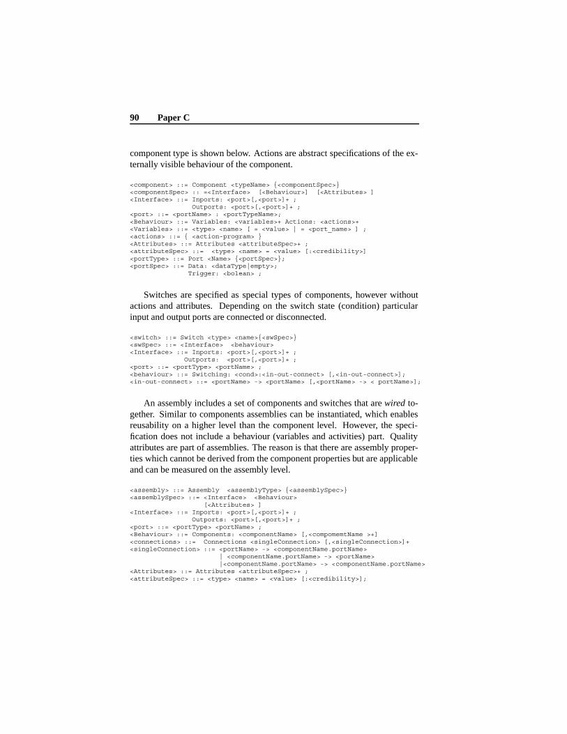
90 Paper C
component type is shown below. Actions are abstract specifications of the ex-ternally visible behaviour of the component.
<component> ::= Component <typeName> {<componentSpec>}<componentSpec> :: =<Interface> [<Behaviour>] [<Attributes> ]<Interface> ::= Inports: <port>[,<port>]+ ;
Outports: <port>[,<port>]+ ;<port> ::= <portName> : <portTypeName>;<Behaviour> ::= Variables: <variables>+ Actions: <actions>+<Variables> ::= <type> <name> [ = <value> | = <port_name> ] ;<actions> ::= { <action-program> }<Attributes> ::= Attributes <attributeSpec>+ ;<attributeSpec> ::= <type> <name> = <value> [:<credibility>]<portType> ::= Port <Name> {<portSpec>};<portSpec> ::= Data: <dataType|empty>;
Trigger: <bolean> ;
Switches are specified as special types of components, however withoutactions and attributes. Depending on the switch state (condition) particularinput and output ports are connected or disconnected.
<switch> ::= Switch <type> <name>{<swSpec>}<swSpec> ::= <Interface> <behaviour><Interface> ::= Inports: <port>[,<port>]+ ;
Outports: <port>[,<port>]+ ;<port> ::= <portType> <portName> ;<behaviour> ::= Switching: <cond>:<in-out-connect> [,<in-out-connect>];<in-out-connect> ::= <portName> -> <portName> [,<portName> -> < portName>];
An assembly includes a set of components and switches that are wired to-gether. Similar to components assemblies can be instantiated, which enablesreusability on a higher level than the component level. However, the speci-fication does not include a behaviour (variables and activities) part. Qualityattributes are part of assemblies. The reason is that there are assembly proper-ties which cannot be derived from the component properties but are applicableand can be measured on the assembly level.
<assembly> ::= Assembly <assemblyType> {<assemblySpec>}<assemblySpec> ::= <Interface> <Behaviour>
[<Attributes> ]<Interface> ::= Inports: <port>[,<port>]+ ;
Outports: <port>[,<port>]+ ;<port> ::= <portType> <portName> ;<Behaviour> ::= Components: <componentName> [,<compomemtName >+]<connections> ::= Connections <singleConnection> [,<singleConnection>]+<singleConnection> ::= <portName> -> <componentName.portName>
| <componentName.portName> -> <portName>|<componentName.portName> -> <componentName.portName>
<Attributes> ::= Attributes <attributeSpec>+ ;<attributeSpec> ::= <type> <name> = <value> [:<credibility>];
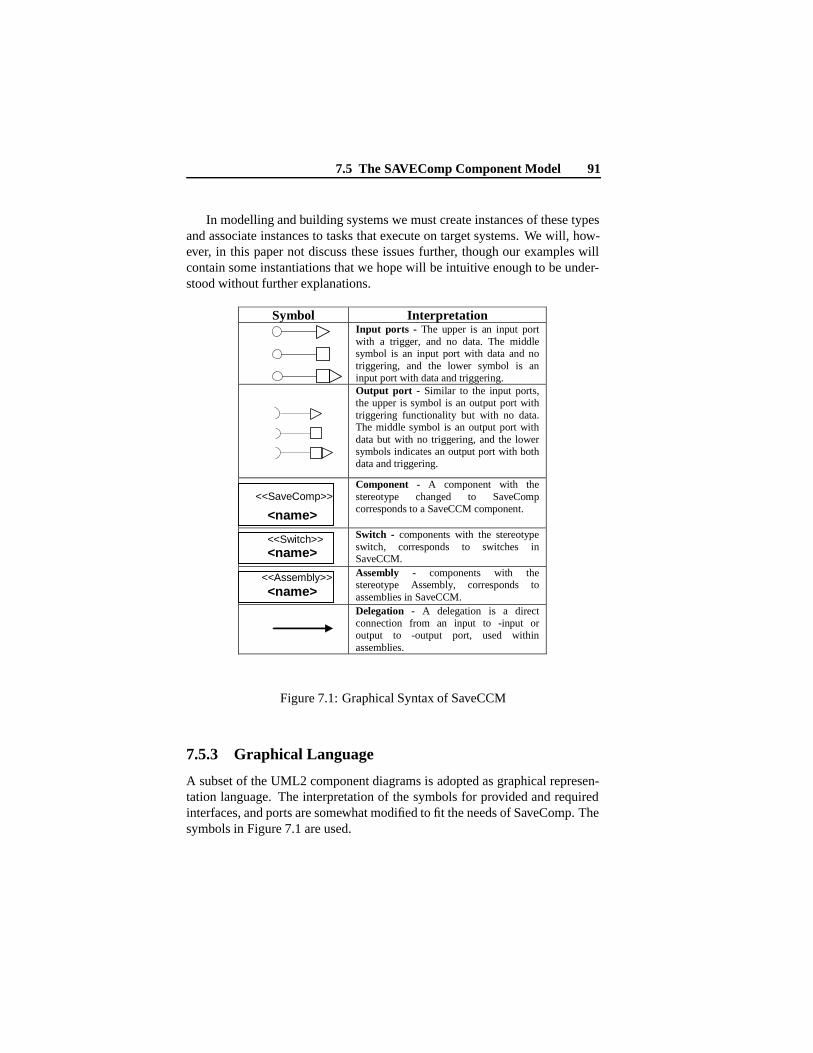
7.5 The SAVEComp Component Model 91
In modelling and building systems we must create instances of these typesand associate instances to tasks that execute on target systems. We will, how-ever, in this paper not discuss these issues further, though our examples willcontain some instantiations that we hope will be intuitive enough to be under-stood without further explanations.
Symbol Interpretation
Input ports - The upper is an input port with a trigger, and no data. The middle symbol is an input port with data and no triggering, and the lower symbol is an input port with data and triggering.
Output port - Similar to the input ports, the upper is symbol is an output port with triggering functionality but with no data. The middle symbol is an output port with data but with no triggering, and the lower symbols indicates an output port with both data and triggering.
Component - A component with the stereotype changed to SaveComp corresponds to a SaveCCM component.
Switch - components with the stereotype switch, corresponds to switches in SaveCCM.
Assembly - components with the stereotype Assembly, corresponds to assemblies in SaveCCM. Delegation - A delegation is a direct connection from an input to -input or output to -output port, used within assemblies.
<<Assembly>> <name>
<<Switch>> <name>
<<SaveComp>>
<name>
Figure 7.1: Graphical Syntax of SaveCCM
7.5.3 Graphical Language
A subset of the UML2 component diagrams is adopted as graphical represen-tation language. The interpretation of the symbols for provided and requiredinterfaces, and ports are somewhat modified to fit the needs of SaveComp. Thesymbols in Figure 7.1 are used.
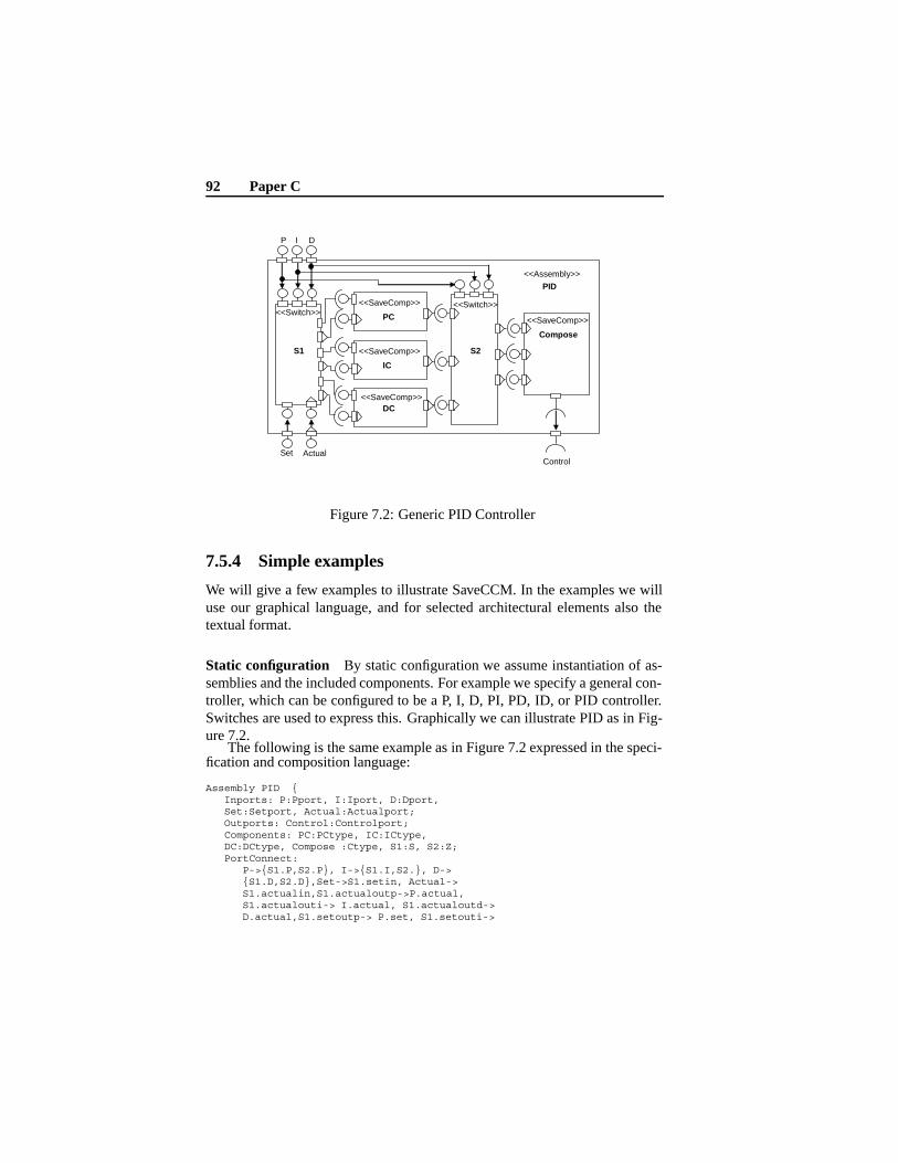
92 Paper C
<<Switch>>
S1
<<SaveComp>>
PC
<<SaveComp>>
IC
<<SaveComp>>DC
<<Switch>>
S2
<<SaveComp>>
Compose
Set Actual
P I D
Control
<<Assembly>>
PID
Figure 7.2: Generic PID Controller
7.5.4 Simple examples
We will give a few examples to illustrate SaveCCM. In the examples we willuse our graphical language, and for selected architectural elements also thetextual format.
Static configuration By static configuration we assume instantiation of as-semblies and the included components. For example we specify a general con-troller, which can be configured to be a P, I, D, PI, PD, ID, or PID controller.Switches are used to express this. Graphically we can illustrate PID as in Fig-ure 7.2.
The following is the same example as in Figure 7.2 expressed in the speci-fication and composition language:
Assembly PID {Inports: P:Pport, I:Iport, D:Dport,Set:Setport, Actual:Actualport;Outports: Control:Controlport;Components: PC:PCtype, IC:ICtype,DC:DCtype, Compose :Ctype, S1:S, S2:Z;PortConnect:
P->{S1.P,S2.P}, I->{S1.I,S2.}, D->{S1.D,S2.D},Set->S1.setin, Actual->S1.actualin,S1.actualoutp->P.actual,S1.actualouti-> I.actual, S1.actualoutd->D.actual,S1.setoutp-> P.set, S1.setouti->
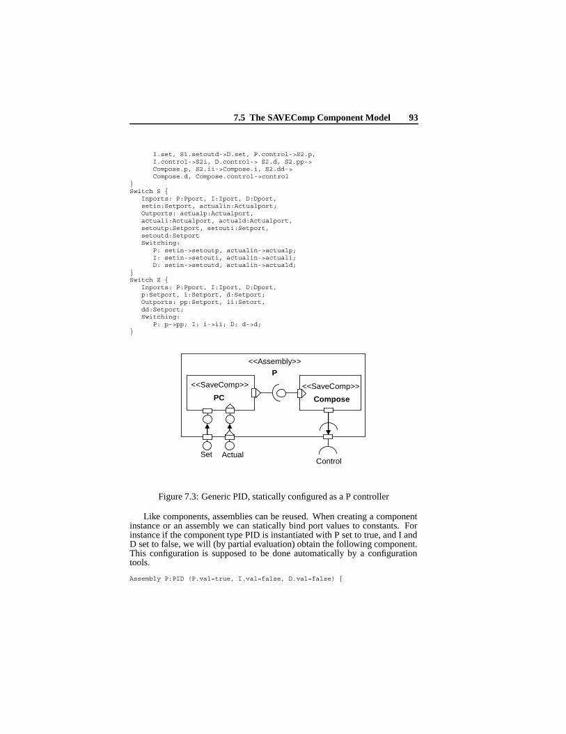
7.5 The SAVEComp Component Model 93
I.set, S1.setoutd->D.set, P.control->S2.p,I.control->S2i, D.control-> S2.d, S2.pp->Compose.p, S2.ii->Compose.i, S2.dd->Compose.d, Compose.control->control
}Switch S {
Inports: P:Pport, I:Iport, D:Dport,setin:Setport, actualin:Actualport;Outports: actualp:Actualport,actuali:Actualport, actuald:Actualport,setoutp:Setport, setouti:Setport,setoutd:SetportSwitching:
P: setin->setoutp, actualin->actualp;I: setin->setouti, actualin->actuali;D: setin->setoutd, actualin->actuald;
}Switch Z {
Inports: P:Pport, I:Iport, D:Dport,p:Setport, i:Setport, d:Setport;Outports: pp:Setport, ii:Setort,dd:Setport;Switching:
P: p->pp; I: i->ii; D: d->d;}
<<SaveComp>>
PC<<SaveComp>>
Compose
<<Assembly>>
P
Set ActualControl
Figure 7.3: Generic PID, statically configured as a P controller
Like components, assemblies can be reused. When creating a componentinstance or an assembly we can statically bind port values to constants. Forinstance if the component type PID is instantiated with P set to true, and I andD set to false, we will (by partial evaluation) obtain the following component.This configuration is supposed to be done automatically by a configurationtools.
Assembly P:PID (P.val=true, I.val=false, D.val=false) {
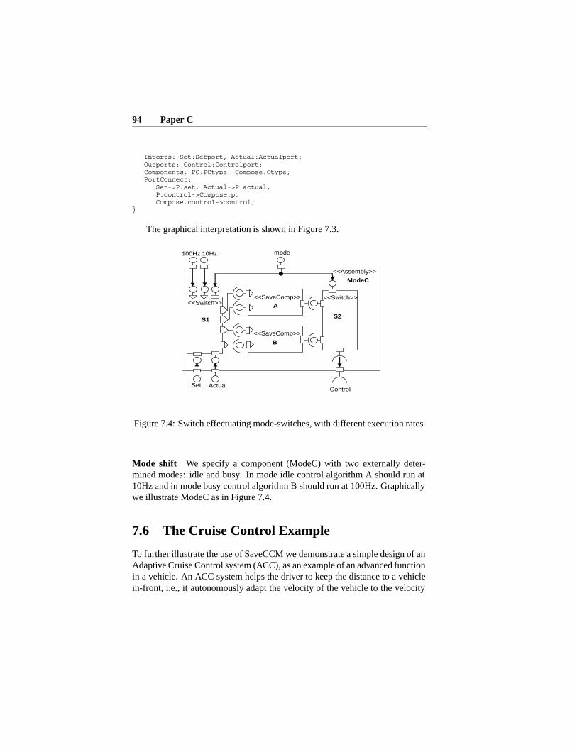
94 Paper C
Inports: Set:Setport, Actual:Actualport;Outports: Control:Controlport:Components: PC:PCtype, Compose:Ctype;PortConnect:
Set->P.set, Actual->P.actual,P.control->Compose.p,Compose.control->control;
}
The graphical interpretation is shown in Figure 7.3.
<<Switch>>
S1
<<SaveComp>>
A
<<SaveComp>>
B
<<Switch>>
S2
100Hz 10Hz mode
<<Assembly>>
ModeC
Set ActualControl
Figure 7.4: Switch effectuating mode-switches, with different execution rates
Mode shift We specify a component (ModeC) with two externally deter-mined modes: idle and busy. In mode idle control algorithm A should run at10Hz and in mode busy control algorithm B should run at 100Hz. Graphicallywe illustrate ModeC as in Figure 7.4.
7.6 The Cruise Control Example
To further illustrate the use of SaveCCM we demonstrate a simple design of anAdaptive Cruise Control system (ACC), as an example of an advanced functionin a vehicle. An ACC system helps the driver to keep the distance to a vehiclein-front, i.e., it autonomously adapt the velocity of the vehicle to the velocity
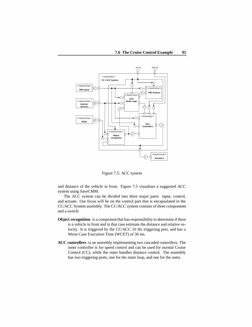
7.6 The Cruise Control Example 95
<<SaveComp>>
HMI inputs
<<SaveComp>>
InternalSensors
<<SaveComp>>
Radar
<<Assembly>>
CC / ACC System
<<SaveComp>>
Object recognition
<<SaveComp>>
ACCMode Logic
<<Assembly>>
ACCControllers
<<SaveComp>>
Actuators
<<SaveComp>>
HMI Outputs
10 Hz 100 Hz
Figure 7.5: ACC system
and distance of the vehicle in front. Figure 7.5 visualises a suggested ACCsystem using SaveCMM.
The ACC system can be divided into three major parts: input, control,and actuate. Our focus will be on the control part that is encapsulated in theCC/ACC System assembly. The CC/ACC system consists of three componentsand a switch:
Object recognition is a component that has responsibility to determine if thereis a vehicle in front and in that case estimate the distance and relative ve-locity. It is triggered by the CC/ACC 10 Hz triggering port, and has aWorst Case Execution Time (WCET) of 30 ms.
ACC controllers is an assembly implementing two cascaded controllers. Theinner controller is for speed control and can be used for normal CruiseControl (CC), while the outer handles distance control. The assemblyhas two triggering ports, one for the inner loop, and one for the outer.
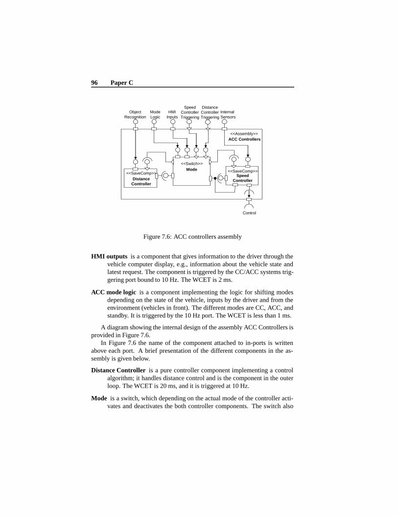
96 Paper C
<<Assembly>>ACC Controllers
<<SaveComp>>Distance
Controller
<<Switch>>Mode <<SaveComp>>
SpeedController
ObjectRecognition
HMIInputs
InternalSensors
ModeLogic
DistanceControllerTriggering
Control
SpeedControllerTriggering
Figure 7.6: ACC controllers assembly
HMI outputs is a component that gives information to the driver through thevehicle computer display, e.g., information about the vehicle state andlatest request. The component is triggered by the CC/ACC systems trig-gering port bound to 10 Hz. The WCET is 2 ms.
ACC mode logic is a component implementing the logic for shifting modesdepending on the state of the vehicle, inputs by the driver and from theenvironment (vehicles in front). The different modes are CC, ACC, andstandby. It is triggered by the 10 Hz port. The WCET is less than 1 ms.
A diagram showing the internal design of the assembly ACC Controllers isprovided in Figure 7.6.
In Figure 7.6 the name of the component attached to in-ports is writtenabove each port. A brief presentation of the different components in the as-sembly is given below.
Distance Controller is a pure controller component implementing a controlalgorithm; it handles distance control and is the component in the outerloop. The WCET is 20 ms, and it is triggered at 10 Hz.
Mode is a switch, which depending on the actual mode of the controller acti-vates and deactivates the both controller components. The switch also

7.6 The Cruise Control Example 97
switches the input of the speed controller, between HMI Inputs (CCfunctionality) and from the control signal of the outer loop controller(ACC functionality).
The speed controller executes with a rate five times faster than the rate of thedistance controller due to faster dynamics, it control the speed of thevehicle. The WCET is 5 ms.
As illustrated by the example, SaveCCM is designed to seamless and eas-ily support typical requirements that arise when designing advanced vehicu-lar functionality, e.g., connections with data, triggering and both, assemblies,feedback, and mode changes.
As an illustration how the above SaveCCM specification can be used inanalysis of timing properties, let us (somewhat simplified) assume that theCC/ACC System will be exclusively allocated to an ECU and that each compo-nent is allocated to a single task. We further assume that the tasks are executingunder a fixed priority (FPS) real-time kernel, with a zero execution time over-head, and that the deadline attributes of the components are defined to be equalto the periods. Given this, and using deadline monotonic priority assignment,together with the execution time attributes of the components, we can derivethe task set in Table 7.1 for the ACC mode.
Task Period (ms) WCET (ms) PrioObject Recognition 100 30 5
Mode Logic 100 1 4HMI Outputs 100 2 3
Distance Controller 100 20 2Speed Controller 20 5 1
Table 7.1: The resulting task set
The task set can be used as input to standard fixed-priority schedulabilityanalysis tools (e.g. [12]). We can use such a tool to verify if the deadlineattributes are satisfied. By applying this analysis we find that the all dead-line attributes are satisfied, hence we can from now on treat these attributes asproperties of the current configuration of the CC/ACC System.

98 Paper C
7.7 Conclusions and further work
We have presented SaveCCM, a component mode intended for embedded con-trol applications in vehicular systems. In contrast with most current compo-nent technologies, SaveCCM is sacrificing flexibility to facilitate analysis; inparticular analysis of dependability and real-time. We illustrate SaveCCM bya simple example, where we also, as an example of timing analysis, show thatSaveCCM models are amenable to schedulabilty analysis.
This paper covers only parts of the component specifications. In our futurework we will provide a complete and formal definition of SaveCCM, as wellas linking it to further methods and tools for both dependability and timinganalysis. Parts of the specifications not discussed here include actions andattributes describing dynamic behaviour of the components and attribute valuesthat are used for reasoning about system properties.
Bibliography
[1] R. van Ommering, F. van der Linden, and J. Kramer. The koala compo-nent model for consumer electronics software. In IEEE Computer, pages78–85. IEEE, March 2000.
[2] M. de Jonge, J. Muskens, and M. Chaudron. Scenario-based predictionof run-time resource consumption in component-based software systems.In Proceedings of the 6th ICSE Workshop on Component-Based SoftwareEngineering (CBSE6), May 2003.
[3] C. Norström, M. Gustafsson, K. Sandström, J. Mäki-Turja, andN. Bånkestad. Experiences from introducing state-of-the-art real-timetechniques in the automotive industry. In In Eigth IEEE InternationalConference and Workshop on the Engineering of Compute-Based SystemsWashington, US. IEEE, April 2001.
[4] K. C. Wallnau and J. Ivers. Snapshot of ccl: A language for predictableassembly. Technical report, Software Engineering Institute, CarnegieMellon University, 2003. CMU/SEI-2003-TN-025.
[5] K. C. Wallnau. Volume III: A Component Technology for PredictableAssembly from Certifiable Components. Technical report, Software En-gineering Institute, Carnegie Mellon University, April 2003.
[6] P. Müller, C. Stich, and C. Zeidler. Components @ work: Componenttechnology for embedded systems. In Proceedings of the 27th Interna-tional Euromicro Conference, 2001.
[7] Save project. http://www.mrtc.mdh.se/SAVE/ (Last Accessed: 2005-01-18).
99
[8] East, embedded electronic architecture project. http://www.east-eea.net/(Last Accessed: 2005-01-18).
[9] O. Bridal C. Norström S. Larsson H. Lönn M. Strömberg H. Hans-son, H. Lawson. Basement: An architecture and methodology for dis-tributed automotive real-time systems. IEEE Transactions on Computers,46(9):1016–1027, Sep 1997.
[10] C. Norström D. Isovic. Building Reliable Component-Based SoftwareSystems, chapter Components in Real-time systems. Artech House Pub-lishers, July 2002. ISBN 1-58053-327-2.
[11] M. Shaw and D. Garlan. Software Architecture: Perspectives on anEmerging Dicipline. ISBN 0-13-182957-2. Prentice-Hall, 1996.
[12] Mast - modeling and analysis suite for real-time applications.http://mast.unican.es/.
Chapter 8
Paper D:Introducing a ComponentTechnology for SafetyCritical EmbeddedReal-Time Systems
Kristian Sandström, Johan Fredriksson, and Mikael ÅkerholmIn International Symposium on Component-based Software Engineering (CBSE7),Edinburgh, Scotland, May 2004
101

Abstract
Safety critical embedded real-time systems represent a class of systems thathas attracted relatively little attention in research addressing component basedsoftware engineering. Hence, the most widely spread component technologiesare not used for resource constrained safety critical real-time systems. They aresimply to resource demanding, to complex and to unpredictable. In this paperwe show how to use component based software engineering for low footprintsystems with very high demands on safe and reliable behaviour. The key con-cept is to provide expressive design time models and yet resource effectiverun-time models by statically resolve resource usage and timing by powerfulcompile time techniques. This results in a component technology for resourceeffective and temporally verified mapping of a component model to a commer-cial real-time operating system.

8.1 Introduction 103
8.1 Introduction
The vehicle domain represents a class of embedded real-time systems wherethe requirements on safety, reliability, resource usage, and cost leaven all throughdevelopment. Historically, the development of such systems has been doneusing only low level programming languages, to guarantee full control overthe system behaviour. As the complexity and the amount of functionality im-plemented by software increase, so does the cost for software development.Therefore it is important to introduce software development paradigms that in-crease software development productivity. Furthermore, since product linesare common within the domain, issues of commonality and reuse is central forreducing cost as well as increasing reliability.
Component based software engineering is a promising approach for ef-ficient software development, enabling well defined software architectures aswell as reuse. Although component technologies have been developed address-ing different demands and domains, there are few component technologiestargeting the specific demands of safety critical embedded real-time systems.Critical for the safe and reliable operation of these systems is the real-time be-haviour, where the timeliness of computer activities is essential. To be ableto guarantee these properties it is necessary to apply real-time systems theory.Thus, a component technology to be used within this domain has to addressspecification, analysis, and implementation of real-time behaviour.
A typical real-time constraint is a deadline on a transaction of co-operatingactivities. A transaction in these systems would typically sample informationabout the environment, perform calculations based on that information and ac-cordingly apply a response to the environment, all within a limited time frame.Also important is the ability to constrain the variation in periodicity of an activ-ity (jitter). The reason for this is that variations in periodicity of observationsof the environment and responses to the same, will affect the control perfor-mance. Hence, a component technology for this domain should have the abilityto clearly express and efficiently realize these constraints [1],[2],[3],[4].
The work described in this paper present a component technology for safetycritical embedded real-time systems that is based on experience from our previ-ous work with introducing state-of-the-art real-time technology in the vehicleindustry. The benefits in development have been discussed in [5] and havealso been proven by long industrial use. That real-time technology has beenincorporated in the Rubus development suite and has been further developed[6]. Experience from the industrial application of the research reveals that aproper component model is not enough; success requires an unbroken chain of

104 Paper D
models, methods, and tools from early design to implementation and run-timeenvironment.
The contribution of the work presented in this paper includes a compo-nent technology for resource effective and temporally verified mapping of acomponent model to a resource structure such as a commercial Real-Time Op-erating System (RTOS). This is made possible by introduction of a componentmodel that support specification of high level real-time constraints, by present-ing a mapping to a real-time model permitting use of standard real-time theory.Moreover, it supports synthesis of run-time mechanisms for predictable execu-tion according to the temporal specification in the component model. Further-more, in this work some limitations in previous work with respect to specifi-cation and synthesis of real-time behaviour are removed. These limitations arepartially discussed in [5] and is mainly related to jitter and execution behaviour.
Many common component technologies are not used for resource con-strained systems, nor safety critical, neither real-time systems. They are simplyto resource demanding, to complex and unpredictable. The research commu-nity has paid attention to the problem, and recent research has resulted in devel-opment of more suitable technologies for these classes of systems. Philips useKoala [7], designed for resource constrained systems, but without support forreal-time verification. Pecos [8] is a collaboration project between ABB andUniversity partners with focus on a component technology for field devices.The project considers different aspects related to real-time and resource con-strained systems, during composition they are using components without codeintrospection possibilities that might be a problem for safety critical applica-tions. Rubus OS [6] is shipped with a component technology with support forprediction of real-time behaviour, though not directly on transactions and jitterconstraints and not on sporadic activities. Stewart, Volpe, and Khosla suggesta combination of object oriented design and port automaton theory called PortBased Objects [9]. The port automaton theory gives prediction possibilitiesfor control applications, although not for transactions and jitter constraints dis-cussed in this paper. Schmidt and Reussner propose to use transition functionsto model and predict reliability in [10]; they are not addressing real-time be-haviour. Wallnau et al. suggest to restrict the usage of component technologies,to enable prediction of desired run-time attributes in [11], the work is generaland not focused on particular theories and methods like the work presented inthis paper.
The outline of the rest of this paper is as follows; section 2 gives an overviewof the component technology. In section 3 the component model is describedand its transformation to a real-time model is explained in section 4. Section
8.2 Component Technology 105
5 presents the steps for synthesis of real-time attributes and discusses run-timesupport. Finally, in section 6, future work is discussed and the paper is con-cluded.
8.2 Component Technology
In this section we will give an overview of the component technology facil-itating component based software development for safety-critical embeddedreal-time systems. We will hereafter refer to this component technology as theAutoComp technology. A key concept in AutoComp is that it allows engineersto practise Component Based Software Engineering (CBSE) without involv-ing heavy run-time mechanisms; it relies on powerful design and compile-timemechanisms and simple and predictable run-time mechanisms. AutoComp isseparated into three different parts; component model, real-time model andrun-time system model. The component model is used during design timefor describing an application. The model is then transformed into a real-timemodel providing theories for synthesis of the high level temporal constraintsinto attributes of the run-time system model. An overview of the technologycan be seen in Fig. 8.1. The different steps in the figure is divided into de-sign time, compile time, and run-time to display at which point in time duringdevelopment they are addressed or used.
During design time, developers are only concerned with the componentmodel and can practise CBSE fully utilizing its advantages. Moreover, highlevel temporal constraints in form of end-to-end deadlines and jitter are sup-ported. Meaning that developers are not burdened with the task of setting artifi-cial requirements on task level, which is essential [12], [5]. It is often natural toexpress timing constraints in the application requirements as end-to-end con-straints.
The compile time steps, illustrated in Fig. 8.1, incorporate a transition fromthe component based design, to a real-time model enabling existing real-timeanalysis and mapping to a RTOS. During this step the components are replacedby real-time tasks. Main concerns in this phase are allocation of components totasks, assignment of task attributes, and real-time analysis. During attribute as-signment, run-time attributes that are used by the underlying operating systemare assigned to the tasks. The attributes are determined so that the high levelconstraints specified by the developer during the design step are met. Finally,when meeting the constraints of the system, a synthesis step is executed. Itis within this step the binary representation of the system is created, often the

106 Paper D
operating system and run-time system are also included with the applicationcode in a single bundle
Real-TimeAnalysis
Real-time model
Synthesis
Design-Time
Compile-Time
Run- Time
Target application
Component model
Model transformation
RTOS
t
Figure 8.1: The AutoComp component technology
The run-time system is assumed to be a traditional RTOS with Fixed Prior-ity Scheduling (FPS) of tasks. Most commercial RTOS can be classified intothis category; furthermore they are simple, resource efficient and many real-time analysis techniques exist. In some cases a layer providing run-time sup-port for the tasks has to be implemented in order to fully support FPS modelsused in real-time theory.
8.3 Component Model
Vehicles present a heterogeneous environment where the interaction betweenthe computer system and the vehicle take different forms. Some vehicle func-tionality requires periodic execution of software, e.g., feedback control, whereasother functionality has a sporadic nature, e.g., alarms. Although vehicle con-trol plays a central role, there is also an abundance of other functionality invehicles that is less critical and has other characteristics, e.g., requires moreflexibility. Although less critical, many of these functions will still interact
8.3 Component Model 107
with other more critical parts of the control system, consider for example di-agnostics. We present a model that in a seamless way allows the integration ofdifferent functionality, by supporting early specification of the high level tem-poral constraints that a given functionality has to meet. Moreover, the compu-tational model is based on a data flow style that results in simple applicationdescriptions and system implementations that are relatively straightforward toanalyse and verify. The data flow style is commonly used within the embeddedsystems domain, e.g., in IEC 61131 used for automation [13] and in Simulinkused for control modelling [14].
The definition of the AutoComp component model is divided into compo-nents, component interfaces, composition, the components invocation cycle,transactions and system representation. In Fig. 8.2 the component model isillustrated using UML2, which could be a possible graphical representationduring design.
The components are defined as glass box, meaning that a developer can seethe code of a component for introspection purposes. It does not mean that a de-veloper has to look into a component during normal composition, and not thatit is allowed to modify a component. The introspection possibility is a require-ment during verification of safety critical applications in order to gain com-plete knowledge about components behaviour. Furthermore, the componentscan only exchange data with each others through data ports. A component canbe a composite containing a complete subsystem, or a basic component withan entry function. Composite components can be treated as any other compo-nent during composition, but it is also possible to enter a composite and changetiming requirements and other properties. The entry function provided by non-composite components can be compared to the entry function for a computerprogram, meaning that the contained number of functions of the componentcan be arbitrary.
The interfaces offered by a component can be grouped into the two classesdata and control interfaces. The data interfaces are used to specify the data flowbetween components, and consist of data ports. Data ports have a specified typeand can be either provided or required. Provided ports are the ports providedby components for input, i.e., the ports a component reads data from. Requiredports are the ports a component writes data to. A component also has a controlinterface with a mandatory control sink, and an optional control source. Thecontrol interface is used for specifying the control flow in the application, i.e.,when or as a response to what component should be triggered. The control sinkis used for triggering the functionality inside the component, while the controlsource is used for triggering other components.
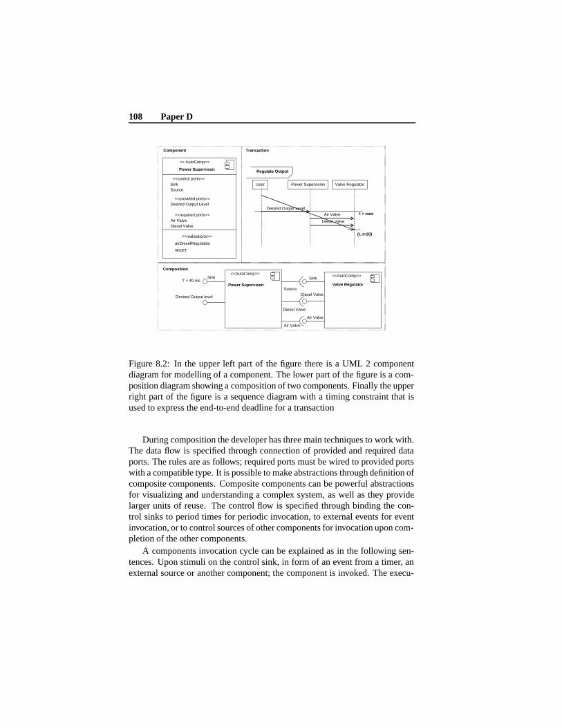
108 Paper D
<< AutoComp>>
Power Supervison
<<provided ports>> Desired Output Level
<<required ports>> Air Valve Diesel Valve
<<realisations>>
airDieselRegulation
<<AutoComp>>
Power Supervison
Desired Output level
Source
Diesel Valve
Sink
Diesel Valve
<<AutoComp>>
Valve Regulator
Regulate Output
User Power Supervision Valve Regulator
Desired Output Level
Air Valve
Diesel Valve
t = now
{t..t+20}
Component
Composition
Transaction
Sink Source
WCET
Sink T = 40 ms
Air Valve
Air Valve
<<control ports>>
Figure 8.2: In the upper left part of the figure there is a UML 2 componentdiagram for modelling of a component. The lower part of the figure is a com-position diagram showing a composition of two components. Finally the upperright part of the figure is a sequence diagram with a timing constraint that isused to express the end-to-end deadline for a transaction
During composition the developer has three main techniques to work with.The data flow is specified through connection of provided and required dataports. The rules are as follows; required ports must be wired to provided portswith a compatible type. It is possible to make abstractions through definition ofcomposite components. Composite components can be powerful abstractionsfor visualizing and understanding a complex system, as well as they providelarger units of reuse. The control flow is specified through binding the con-trol sinks to period times for periodic invocation, to external events for eventinvocation, or to control sources of other components for invocation upon com-pletion of the other components.
A components invocation cycle can be explained as in the following sen-tences. Upon stimuli on the control sink, in form of an event from a timer, anexternal source or another component; the component is invoked. The execu-
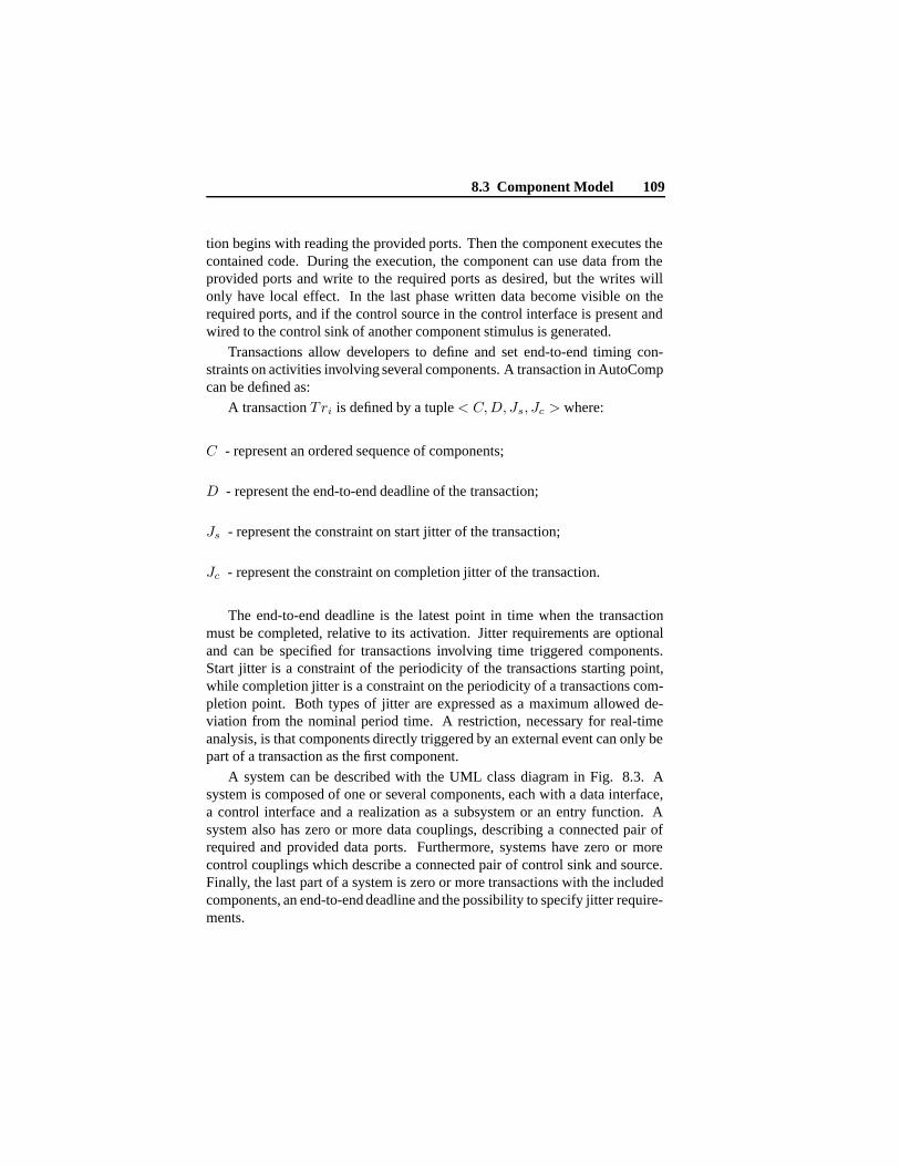
8.3 Component Model 109
tion begins with reading the provided ports. Then the component executes thecontained code. During the execution, the component can use data from theprovided ports and write to the required ports as desired, but the writes willonly have local effect. In the last phase written data become visible on therequired ports, and if the control source in the control interface is present andwired to the control sink of another component stimulus is generated.
Transactions allow developers to define and set end-to-end timing con-straints on activities involving several components. A transaction in AutoCompcan be defined as:
A transaction Tri is defined by a tuple < C, D, Js, Jc > where:
C - represent an ordered sequence of components;
D - represent the end-to-end deadline of the transaction;
Js - represent the constraint on start jitter of the transaction;
Jc - represent the constraint on completion jitter of the transaction.
The end-to-end deadline is the latest point in time when the transactionmust be completed, relative to its activation. Jitter requirements are optionaland can be specified for transactions involving time triggered components.Start jitter is a constraint of the periodicity of the transactions starting point,while completion jitter is a constraint on the periodicity of a transactions com-pletion point. Both types of jitter are expressed as a maximum allowed de-viation from the nominal period time. A restriction, necessary for real-timeanalysis, is that components directly triggered by an external event can only bepart of a transaction as the first component.
A system can be described with the UML class diagram in Fig. 8.3. Asystem is composed of one or several components, each with a data interface,a control interface and a realization as a subsystem or an entry function. Asystem also has zero or more data couplings, describing a connected pair ofrequired and provided data ports. Furthermore, systems have zero or morecontrol couplings which describe a connected pair of control sink and source.Finally, the last part of a system is zero or more transactions with the includedcomponents, an end-to-end deadline and the possibility to specify jitter require-ments.
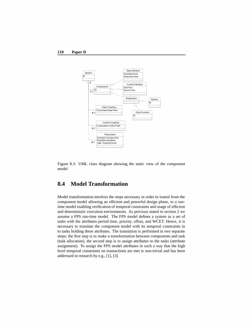
110 Paper D
System
ID
Entry Function
ID
Data Interface
Provided PortsRequired Ports
Control Interface
Sink PortSource Port
Realisation
Transaction
Included ComponentsEnd2End DeadlineJitter Requirements
Data Coupling
Connected Data Ports
Component
ID
Control Coupling
Connected Control Ports
System
ID
0..*0..*
0..*0..*
1..*
1
1..*
1
0..*0..*
Figure 8.3: UML class diagram showing the static view of the componentmodel
8.4 Model Transformation
Model transformation involves the steps necessary in order to transit from thecomponent model allowing an efficient and powerful design phase, to a run-time model enabling verification of temporal constraints and usage of efficientand deterministic execution environments. As previous stated in section 2 weassume a FPS run-time model. The FPS model defines a system as a set oftasks with the attributes period time, priority, offset, and WCET. Hence, it isnecessary to translate the component model with its temporal constraints into tasks holding these attributes. The translation is performed in two separatesteps; the first step is to make a transformation between components and task(task allocation), the second step is to assign attributes to the tasks (attributeassignment). To assign the FPS model attributes in such a way that the highlevel temporal constraints on transactions are met is non-trivial and has beenaddressed in research by e.g., [1], [3].
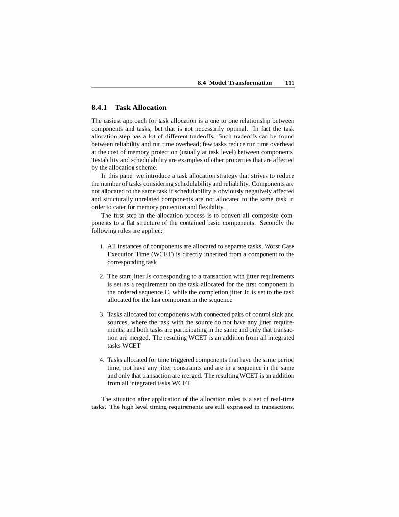
8.4 Model Transformation 111
8.4.1 Task Allocation
The easiest approach for task allocation is a one to one relationship betweencomponents and tasks, but that is not necessarily optimal. In fact the taskallocation step has a lot of different tradeoffs. Such tradeoffs can be foundbetween reliability and run time overhead; few tasks reduce run time overheadat the cost of memory protection (usually at task level) between components.Testability and schedulability are examples of other properties that are affectedby the allocation scheme.
In this paper we introduce a task allocation strategy that strives to reducethe number of tasks considering schedulability and reliability. Components arenot allocated to the same task if schedulability is obviously negatively affectedand structurally unrelated components are not allocated to the same task inorder to cater for memory protection and flexibility.
The first step in the allocation process is to convert all composite com-ponents to a flat structure of the contained basic components. Secondly thefollowing rules are applied:
1. All instances of components are allocated to separate tasks, Worst CaseExecution Time (WCET) is directly inherited from a component to thecorresponding task
2. The start jitter Js corresponding to a transaction with jitter requirementsis set as a requirement on the task allocated for the first component inthe ordered sequence C, while the completion jitter Jc is set to the taskallocated for the last component in the sequence
3. Tasks allocated for components with connected pairs of control sink andsources, where the task with the source do not have any jitter require-ments, and both tasks are participating in the same and only that transac-tion are merged. The resulting WCET is an addition from all integratedtasks WCET
4. Tasks allocated for time triggered components that have the same periodtime, not have any jitter constraints and are in a sequence in the sameand only that transaction are merged. The resulting WCET is an additionfrom all integrated tasks WCET
The situation after application of the allocation rules is a set of real-timetasks. The high level timing requirements are still expressed in transactions,
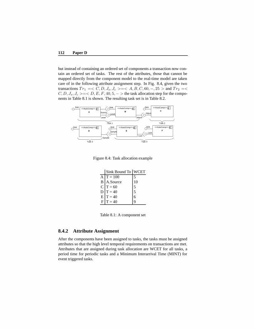
112 Paper D
but instead of containing an ordered set of components a transaction now con-tain an ordered set of tasks. The rest of the attributes, those that cannot bemapped directly from the component model to the real-time model are takencare of in the following attribute assignment step. In Fig. 8.4, given the twotransactions Tr1 =< C, D, Js, Jc >=< A, B, C, 60,−, 25 > and Tr2 =<C, D, Js, Jc >=< D, E, F , 40, 5,− > the task allocation step for the compo-nents in Table 8.1 is shown. The resulting task set is in Table 8.2.
<<AutoComp>>
A
<<AutoComp>>
B
<<AutoComp>>
C
Sink Sink
Source
Sink
<<AutoComp>>
F
Sink
Level
Level
Adjust
Adjust
<<AutoComp>>
E
Sink
Lock
Lock
Task 1 Task 2
Task 4
<<AutoComp>>
D
Sink
Task 3
Sample
Sample
Figure 8.4: Task allocation example
Sink Bound To WCETA T = 100 5B A.Source 10C T = 60 5D T = 40 5E T = 40 6F T = 40 9
Table 8.1: A component set
8.4.2 Attribute Assignment
After the components have been assigned to tasks, the tasks must be assignedattributes so that the high level temporal requirements on transactions are met.Attributes that are assigned during task allocation are WCET for all tasks, aperiod time for periodic tasks and a Minimum Interarrival Time (MINT) forevent triggered tasks.
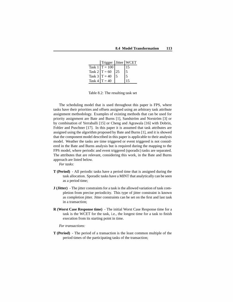
8.4 Model Transformation 113
Trigger Jitter WCETTask 1 T = 100 15Task 2 T = 60 25 5Task 3 T = 40 5 5Task 4 T = 40 15
Table 8.2: The resulting task set
The scheduling model that is used throughout this paper is FPS, wheretasks have their priorities and offsets assigned using an arbitrary task attributeassignment methodology. Examples of existing methods that can be used forpriority assignment are Bate and Burns [1], Sandström and Norström [3] orby combination of Yerraballi [15] or Cheng and Agrawala [16] with Dobrin,Fohler and Puschner [17]. In this paper it is assumed that task attributes areassigned using the algorithm proposed by Bate and Burns [1], and it is showedthat the component model described in this paper is applicable to their analysismodel. Weather the tasks are time triggered or event triggered is not consid-ered in the Bate and Burns analysis but is required during the mapping to theFPS model, where periodic and event triggered (sporadic) tasks are separated.The attributes that are relevant, considering this work, in the Bate and Burnsapproach are listed below.
For tasks:
T (Period) - All periodic tasks have a period time that is assigned during thetask allocation. Sporadic tasks have a MINT that analytically can be seenas a period time;
J (Jitter) - The jitter constraints for a task is the allowed variation of task com-pletion from precise periodicity. This type of jitter constraint is knownas completion jitter. Jitter constraints can be set on the first and last taskin a transaction;
R (Worst Case Response time) - The initial Worst Case Response time for atask is the WCET for the task, i.e., the longest time for a task to finishexecution from its starting point in time.
For transactions:
T (Period) - The period of a transaction is the least common multiple of theperiod times of the participating tasks of the transaction;
114 Paper D
End-to-End deadline - Transactions have a requirement that all tasks havefinished their execution within a certain time from the transactions pointof start in time.
In Bate and Burns approach additional attributes, such as deadline and sep-aration for tasks and jitter requirements for transactions are considered. Inthis paper those attributes are disregarded since there are no such requirementsin the previously described component model. It is trivial to see that fromthe component model, the period and jitter constraints match the model pro-posed by Bate and Burns. The initial worst case response time R is assignedthe WCET value in the component model. For the transaction the end-to-enddeadline requirements match the transaction deadline of the Bate and Burnsmodel. The period time of the transaction is derived from the least commonmultiple of the period of the tasks participating in the transaction.
The next step is naturally to assign the FPS model with run-time and anal-ysis attributes. The new attributes priority and offsets will be derived throughexisting analysis methods [1]. The new parameters for the FPS model are de-scribed below.
P (Priority) - The priority is an attribute that indicates the importance of thetask relative to other tasks in the system. In a FPS system tasks arescheduled according to their priority, the task with the highest priority isalways executed first. All tasks in the system are assigned a priority;
O (Offset) - The offset is an attribute that periodic tasks with jitter constraintsare assigned. The earliest start time is derived by adding the offset to theperiod time.
In Table 8.3 it is summarized what attributes belonging to time triggeredand event triggered tasks in the FPS model.
Attribute Time triggered Event triggeredPeriod XMINT X
Priority X XOffset X (Upon Jitter Constraints)
WCET X X
Table 8.3: Attributes associated with time and event triggered tasks

8.4 Model Transformation 115
Applying the Bate and Burns algorithm determines task attributes from thetasks and transactions described in Table 8.2. The resulting run-time attributespriority, offset period and WCET are shown in Table 8.4. The attributes offsetand priority are determined with the Bate and Burns analysis, whilst the periodand WCET are determined in the task allocation.
Priority Offset Period WCETTask 1 2 0 100 15Task 2 1 (Lowest) 35 60 5Task 3 4 (Highest) 0 40 5Task 4 3 0 40 15
Table 8.4: Assigned task attributes
In Fig. 8.5 a run-time trace for an FPS system is shown and the transactionsTr1 and Tr2 are indicated.
Task 1 Task 2 Task 3 Task 4
50 100 150 200 Transaction Tr2
Transaction Tr1
Figure 8.5: Trace of an FPS schedule
When the FPS model has been assigned its attributes it has to be verified.The verification of the model is performed by applying real-time schedulinganalysis to confirm that the model is schedulable with the assigned parame-ters. This is necessary since attribute assignment does not necessarily guaran-tee schedulability, but only assigns attributes considering the relation betweenthe tasks.
8.4.3 Real-Time Analysis
To show that the FPS tasks will meet their stipulated timing constraints, schedu-lability analysis must be performed. Much research has been done with respect
116 Paper D
RTOS
void actuate(if(level >out += -1;}postCreate(
set = initi
Task Assignment
Assignment ofRun-time attributes
SynthesisSynthesis
<<component>>
D
<<component>>
A
<<component>>
B
<<component>>
C
Data port connections
Code
RTOS characteristics and Run-Time system
Run-Time System
Executable Reliable BundleFor Embedded Systems
Figure 8.6: The steps of synthesizing code for the run-time system
to analysis of different properties of FPS systems, and all those results areavailable for use, once a FPS model has been established. The temporal analy-sis of an FPS system with offsets, sporadic tasks and synchronization has beencovered in research by e.g., Palencia et al. [18], [19] and Redell [20].
The output from the analysis is whether the system is feasible or not in theworst case. If the analysis shows that the system is infeasible, the parts that cannot keep its requirements are either changed and reanalysed or emphasised forthe developer to make changes.
8.5 Synthesis
The next step after the model transformation and real-time analysis is to syn-thesise code for the run-time system. This includes mapping the tasks to oper-ating system specific task entities, mapping data connections to an OS specificcommunication, modifying the middleware, generating glue code, compiling,linking and bundling the program code (see Fig. 8.6).
The synthesis is divided into two major parts. Given a task set and nec-essary information about the run-time system, the synthesis generates codeconsidering communication, synchronization.
• The first part in synthesis is to resolve the communication within andbetween tasks. Two communicating components that are assigned todifferent tasks will form an Inter Task Communication (ITC) while com-

8.5 Synthesis 117
<<component >>
A <<component>>
B <<component>>
C
<<component >>
A <<component>>
B <<component>>
C
Middleware Middleware
Figure 8.7: A component model with adjustments for different operating sys-tems to promote platform independence
munication between components assigned to the same task are realizedwith shared data spaces within the task. The ITC is later mapped tooperating system specific communication directives.
• The other part in the synthesis is to resolve the control couplings, i.e.,the sink and source. If a tasks starting point is dependent on the formertasks finishing point the tasks have to be synchronized. The synchro-nization is solved through scheduling. The synthesis will generate codefor scheduling periodic tasks, handle the control flow between tasks andconsider offsets. The code generated for the periodic scheduling andoffsets is dependent on the middleware and can be realized as a configu-ration file or actual code in each task. Invocations of sporadic tasks aremapped to event handlers in the middleware or the operating system.
It is assumed that a middleware is present as shown in Fig. 9.3, for eachplatform and that it provides functionality that the component model needs butthe operating system does not provide. The more functionality the operatingsystem provides, the smaller the middleware has to be. The middleware en-capsulates core communication and concurrency services to eliminate manynon-portable aspects of developing and is hence platform specific in favourof a platform independent component model. Typical functionality that is notprovided by most commercial RTOS is periodicity and support for offsets. Themiddleware also need to support sink and source couplings since task coupledwith its source need to be able to invoke the corresponding task. The run-timesystem conforms to FPS and hence the run-time task model is similar to the
118 Paper D
previously described FPS model with some exceptions. The worst case exe-cution time is merely an analysis attribute and is not needed in the run-timemodel. The MINT is usually a requirement on the environment rather than atask attribute, and is thus also analytical and unnecessary. Hence the run-timetask model is for periodic tasks Period time, Priority, Offset and for sporadictasks Priority.
8.6 Conclusions and Future Work
In this paper we show how to use component based software engineering forlow footprint systems with very high demands on safe and reliable behaviour.The key concept is to provide expressive design time models and yet resourceeffective run-time models by statically resolve resource usage and timing bypowerful compile time techniques.
The work presented in this paper introduces a component technology forresource effective and temporally verified mapping of a component model toa resource structure such as a commercial RTOS. This is made possible byintroduction of a component model that support specification of high level real-time constraints, by presenting a mapping to a real-time model, permittinguse of standard real-time theory, and by synthesis of run-time mechanisms forpredictable execution according to the temporal specification in the componentmodel.
Although the basic concept has been validated by successful industrial ap-plication of previous work [5], it is necessary to further validate the componenttechnology presented here. In order to facilitate this, a prototype implemen-tation of the component technology is under development where the core parthas been completed. The prototype will enable evaluation of different tech-nology realisations with respect to performance. Moreover, parts of the modeltransformation need additional attention, foremost the strategies for allocationof components to tasks. Furthermore, we will make efforts in extending thecomponent model making it more expressive and flexible while still keepingthe ability for real-time analysis. Interesting is also to investigate trade-offsbetween run-time foot print and flexibility with respect to e.g., adding func-tionality post production. Finally, the component technology will be evaluatedin a larger, preferably industrial, case.
Bibliography
[1] A. Bate and I. Burns. An approach to task attribute assignment for unipro-cessor systems. In Proceedings of the 26th Annual International Com-puter Software and Applications Conference. IEEE, 2002.
[2] K. Mok, D. Tsou, and R. C. M. De Rooij. The msp.rtl real-time schedulersynthesis tool. In In Proc. 17th IEEE Real-Time Systems Symposium,pages 118–128. IEEE, 1996.
[3] K. Sandström and C. Norström. Managing complex temporal require-ments in real-time control systems. In In 9th IEEE Conference on Engi-neering of Computer-Based Systems Sweden. IEEE, April 2002.
[4] J. Würtz and K. Schild. Scheduling of time-triggered real-time systems.In In Constraints, Kluwer Academic Publishers, pages 335–357, October2000.
[5] C. Norström, M. Gustafsson, K. Sandström, J. Mäki-Turja, andN. Bånkestad. Experiences from introducing state-of-the-art real-timetechniques in the automotive industry. In In Eigth IEEE InternationalConference and Workshop on the Engineering of Compute-Based SystemsWashington, US. IEEE, April 2001.
[6] Arcticus. Arcticus homepage: http://www.arcticus.se.
[7] R. van Ommering, F. van der Linden, and J. Kramer. The koala compo-nent model for consumer electronics software. In IEEE Computer, pages78–85. IEEE, March 2000.
[8] G. Nierstrasz, S. Arevalo, R. Ducasse, A. Wuyts, P. Black, C. Müller,T. Zeidler, R. Genssler, and A. van den Born. Component model for field
119
120 Bibliography
devices. In Proceedings of the First International IFIP/ACM WorkingConference on Component Deployment, Germany, June 2002.
[9] D. B. Stewart, R. A. Volpe, and P. K. Khosla. Design of dynamically re-configurable real-time software using port-based objects. In IEEE Trans-actions on Software Engineering, pages 759–776. IEEE, December 1997.
[10] W. H. Schmidt and R. H. Reussner. Parameterised contracts and adap-tor synthesis. In Proc. 5th International Workshop of Component-BasedSoftware Engineering (CBSE5), May 2002.
[11] S. A. Hissam, G. A. Moreno, J. Stafford, and K. C. Wallnau. Packag-ing predictable assem-bly with prediction-enabled component technol-ogy. Technical report, November 2001.
[12] D .K . Hammer and M. R. V. Chaudron. Component-based softwareengineering for resource constraint systems: What are the needs? In6th Workshop on Object-Oriented Real-Time Dependable Systems, Rome,Italy, January 2001.
[13] IEC. International standard IEC 1131: Programmable controllers, 1992.
[14] Mathworks. Mathworks homepage : http://www.mathworks.com.
[15] R. Yerraballi. Scalability in Real-Time Systems. PhD thesis, ComputerScience Department, old Dominion University, August 1996.
[16] S. T. Cheng. and Agrawala A. K. Allocation and scheduling of real-timeperiodic tasks with relative timing constraints. In Second InternationalWorkshop on Real-Time Computing Systems and Applications (RTCSA).IEEE, 1995.
[17] R. Dobrin, G. Fohler, and P. Puschner. Translating off-line schedulesinto task attributes for fixed priority scheduling. In In Real-Time SystemsSymposium London, UK, December, 2001.
[18] J. C. Palencia and M. Gonzalez Harbour. Schedulability analysis for taskswith static and dynamic offsets. In Proc. of the 19th Real-Time SystemsSymposium, December 1998.
[19] J. C. Palencia and M. Gonzalez Harbour. Exploiting precedence relationsin the schedulabil-ity analysis of distributed real-time systems. In Proc.of the 20th Real-Time Systems Symposium, December 1999.

[20] O. Redell and M. Törngren. Calculating exact worst case response timesfor static priority scheduled tasks with offsets and jitter. In Proc. EighthIEEE Real-Time and Embedded Tech-nology and Applications Sympo-sium. IEEE, September 2002.


Chapter 9
Paper E:Towards a DependableComponent Technology forEmbedded SystemApplications
Mikael Åkerholm, Anders Möller, Hans Hansson, and Mikael NolinIn Tenth IEEE International Workshop on Object-oriented Real-time Depend-able Systems (WORDS2005), Sedona, Arizona, february, 2005
123

Abstract
Component-Based Software Engineering is a technique that has proven effec-tive to increase reusability and efficiency in development of office and webapplications. Though being promising also for development of embedded anddependable systems, the true potential in this domain has not yet been realized.
In this paper we present a prototype component technology, developed withsafety-critical automotive applications in mind. The technology is illustratedby a case-study, which is also used as the basis for an evaluation and a discus-sion of the appropriateness and applicability in the considered domain. Ourstudy provides initial positive evidence of the suitability of our technology, butdoes also show that it needs to be extended to be fully applicable in an indus-trial context.

9.1 Introduction 125
9.1 Introduction
Software is central to enable functionality in modern electronic products, butit is also the source of a number of quality problems and constitutes a majorpart of the development cost. This is further accentuated by the increasingcomplexity and integration of products. Improving quality and predictabil-ity of Embedded Computer Systems (ECS) are prerequisites to increase, oreven maintain, profitability. Similarly, there is a call for predictability in theECS engineering processes; keeping quality under control, while at the sametime meeting stringent cost and time-to-market constraints. This calls for newsystematic engineering approaches to design, develop, and maintain ECS soft-ware. Component-Based Software Engineering (CBSE) is such a technique,currently used in office applications, but with a still unproven potential for em-bedded dependable software systems. In CBSE, software is structured intocomponents and systems are constructed by composing and connecting thesecomponents. CBSE can be seen as an extension of the object-oriented ap-proach, where components may have additional interfaces compared to tradi-tional method invocation of objects. Similarly to objects, simpler componentscan be aggregated to produce more complex components.
In this paper, we present the ongoing work of devising a component tech-nology for distributed, embedded, safety critical, dependable, resource con-strained real-time systems. Systems with these characteristics are common inmost modern vehicles and in the robotics and automation industries. Hence, wecooperate with leading product companies (e.g. ABB, Bombardier and Volvo)and some of their suppliers (e.g. CC Systems) in order to establish this novelcomponent technology.
Support for dependability can be added at many different abstraction levels(e.g. the source code and the operating system levels). At each level, differ-ent methods and techniques can be used to increase the dependability of thesystem. Our hypothesis is that dependability, together with other key charac-teristics, such as resource efficiency and predictability, should be introducedearly in the software process and supported through all stages of the process.Our view is that dependability, and similar cross-cutting characteristics, cannotbe achieved by addressing only one abstraction level or one phase in the soft-ware life-cycle. Further, we argue that dependability of systems is enhanced bysystematic application of code synthesis. For code synthesis, models of com-ponent behaviour and their resource requirements together with application re-quirements and models of the underlying hardware and operating system areused. The models and requirements are used by resource and timing analysis
126 Paper E
algorithms to ensure that a feasible system is generated.In this paper, we present the current implementation of our component
technology (Section 9.3), together with an example application that illustratesits use (Section 9.4). Based on experiences with the example application, weprovide an evaluation of the technology (Section 9.5).
9.2 CBSE for Embedded Systems
Research in the CBSE community is targeting theories, processes, technolo-gies, and tools, supporting and enhancing a component-based design strategyfor software. A component-based approach for software development distin-guishes component development from system development. Component devel-opment is the process of creating components that can be used and reused inmany applications. System development with components is concerned withassembling components into applications that meet the system requirements.The central technical concepts of CBSE in an embedded setting are:
Software components that have well specified interfaces, and are easy to un-derstand, adapt and deliver. Especially for embedded systems, the com-ponents must have well specified resource requirements, as well as spec-ification of other, for the application relevant properties, e.g., timing,memory consumptions, reliability, safety, and dependability.
Component models that define different component types, their possible in-teraction schemes, and clarify how different resources are bound to com-ponents. For embedded systems the component models should imposedesign restrictions so that systems built from components are predictablewith respect to important properties in the intended domain.
Component frameworks i.e., run-time systems that supports the componentsexecution by handling component interactions and invocation of the dif-ferent services provided by the components. For embedded systems, thecomponent framework typically must be light weighted, and use pre-dictable mechanisms. To enhance predictability, it is desirable to moveas much as possible of the traditional framework functionality from therun-time system to the pre-run-time compile stages.
Component technologies i.e., concrete implementations of component mod-els and frameworks that can be used for building component-based appli-cations. Two of the most well known component technologies are Mi-
9.3 Our Component Technology 127
crosoft’s Components Object Model (COM)1 for desktop applications,and Sun’s Enterprise Java Beans (EJB)2 for distributed enterprise appli-cations.
Efficient development of applications is supported by the component-basedstrategy, which addresses the whole software life-cycle. CBSE can shorten thedevelopment-time by supporting component reuse, and by simplifying paralleldevelopment of components. Maintenance is also supported since the compo-nent assembly is a model of the application, which is by definition consistentwith the actual system. During maintenance, adding new, and upgrading ex-isting components are the most common activities. When using a component-based approach, this is supported by extendable interfaces of the components.Also testing and debugging is enhanced by CBSE, since components are easilysubjected to unit testing and their interfaces can be monitored to ensure correctbehaviour.
CBSE has been successfully applied in development of desktop and enter-prise business applications, but for the domain of embedded systems CBSE hasnot been widely adopted. One reason is the inability of the existing commer-cial technologies to support the requirements of the embedded applications.Component technologies supporting different types of embedded systems haverecently been developed, e.g., from industry [1, 2], and from academia [3], [4].However, as Crnkovic points out in [5], there are much more issues to solvebefore a CBSE discipline for embedded systems can be established, e.g., ba-sic issues such as light-weighted component frameworks and identification ofwhich system properties that can be predicted by component properties.
Based on risks and requirements for applying CBSE for our class of appli-cations, we have collected a check-list with evaluation points that we have usedto evaluate our component technology in an industrial environment. In Section5 we provide a summary of the evaluation, for more details we refer to [6].
9.3 Our Component Technology
Our component technology implements the SaveComp Component Model [7]and provides compile-time mappings to a set of operating systems, follow-ing the technique described in [8]. The component technology is intended toprovide three main benefits for developers of embedded systems: efficient de-velopment, predictable behaviour, and run-time efficiency.
1Microsoft Corporation, The Component Object Model, http://www.microsoft.com2Sun Microsystems, Enterprise JavaBeans Specification, http://www.sun.com
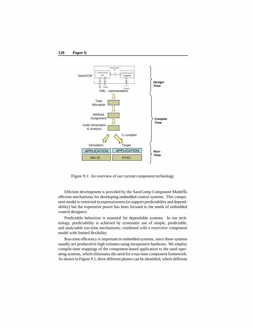
128 Paper E
Task Allocation
Win 32
APPLICATION
SaveCCM
XML - representation
Design-Time
Compile-Time
Run-Time
<<SaveComp>>
PC
<<SaveComp>>
Compose
<<Assembly>>
P
Set ActualControl
AttributeAssignment
Code Generation & Analysis
C-compiler
RTXC
APPLICATION
Simulation Target
Figure 9.1: An overview of our current component technology
Efficient development is provided by the SaveComp Component ModelŠsefficient mechanisms for developing embedded control systems. This compo-nent model is restricted in expressiveness (to support predictability and depend-ability) but the expressive power has been focused to the needs of embeddedcontrol designers.
Predictable behaviour is essential for dependable systems. In our tech-nology, predictability is achieved by systematic use of simple, predictable,and analysable run-time mechanisms; combined with a restrictive componentmodel with limited flexibility.
Run-time efficiency is important in embedded systems, since these systemsusually are produced in high volumes using inexpensive hardware. We employcompile-time mappings of the component-based application to the used oper-ating systems, which eliminates the need for a run-time component framework.As shown in Figure 9.1, three different phases can be identified, where different
9.3 Our Component Technology 129
pieces of the component technology are used:
Design-time SaveCCM is used during design-time for describing the applica-tion.
Compile-time during compile-time the high-level model of the application istransformed into entities of the run-time model, e.g., tasks, system calls,task attributes, and real-time constrains.
Run-time during run-time the application uses the execution model from anunderlying operating system. Currently our component technology sup-ports the RTXC operating system3 and the Microsoft Win32 environ-ment4. The Win32 environment is intended for functional test and debugactivities (using CCSimTech [15]), but it does not support real-time tests.
9.3.1 Design-Time - The Component Model
SaveCCM is a component model intended for development of software for ve-hicular systems. The model is restrictive compared to commercial componentmodels, e.g., COM and EJB. SaveCCM provides three main mechanisms fordesigning applications:
Components which are encapsulated units of behaviour.
Component interconnections which may contain data, triggering for invoca-tion of components, or a combination of both data and triggering.
Switches which allow static and dynamic reconfiguration of component inter-connections.
These mechanisms have been designed to allow common functionality in em-bedded control systems to be implemented. Specific examples of key function-ality supported are:
• Support for implementation of feedback control, with a possibility toseparate calculation of a control signal, from the update of the controllerstate. Something which is common in control applications to minimiselatency between sampling and control.
3Quadros Systems Inc, RTXC Kernel User’s Guide, http://www.quadros.com4MSDN, Win32 Application Programmer’s Interface, http://msdn.microsoft.com/
130 Paper E
• Support for system mode changes, something which is common in, e.g.,vehicular systems.
• Support for static configuration of components to suit a specific productin a product line.
Architectural Elements
The main architectural elements in SaveCCM are components, switches, andassemblies. The interface of an architectural element is defined by a set ofassociated ports, which are points of interaction between the element and itsexternal environment. We distinguish between input- and output ports, andthere are two complementary aspects of ports: the data that can be transferredvia the port, and the triggering of component executions. SaveCCM distinguishbetween these two aspects, and allow three types of ports:
• Data ports are one element buffers that can be read and written. Eachwrite operation to the port will overwrite the previous value stored.
• Triggering ports are used for controlling the activation of elements. Anelement may have several triggering ports. The component is triggeredwhen all input triggering ports are activated. Several output triggeringports may be connected to a single input triggering port, providing OR-semantics.
• Combined ports (data and triggering), combine data and triggering ports,semantically the data is written before the trigger is activated.
An architectural element emits trigger signals and data at its output ports,and receives trigger signals and data at its input ports. Systems are built fromthe architectural elements by connecting input ports to output ports. Ports canonly be connected if their types match, i.e. identical data types are transferredand the triggering coincides.
The basis of the execution model is a control-flow (pipes-and-filters) para-digm [9]. On a high level, an element is either waiting to be activated (trig-gered) or executing. In the first phase of its execution an element read all itsinputs, secondly it performs all computations, and finally it generates outputs.
Components
Components are the basic units of encapsulated behaviour. Components aredefined by an entry function, input and output ports, and, optionally, quality

9.3 Our Component Technology 131
attributes. The entry function defines the behaviour of the component duringexecution. Quality attributes are used to describe particular characteristics ofcomponents (e.g. worst-case execution-time and reliability). A component isnot allowed to have any dependencies to other components, or other externalsoftware (e.g. the operating system), except the visible dependencies throughits input- and output-ports.
Switches
A switch provides means for conditional transfer of data and/or triggering be-tween components. A switch specifies a set of connection patterns, each defin-ing a specific way of connecting the input and output ports of the switch. Log-ical expressions (guards; one for each pattern), based on the data available atsome of the input ports, are used to determine which connection pattern that isto be used.
Switches can be used for specifying system modes, each mode correspond-ing to a specific static configuration. By changing the port values at run-time,a new mode can be activated. By setting a port value to a fixed value at designtime, the compiler can remove unused functionality.
Assemblies
Component assemblies allow composite behaviours to be defined, and make itpossible to form aggregate components from groups of components, switches,and assemblies. In SaveCCM, assemblies are encapsulation of components andswitches, having an external functional interface (just as SaveCCM-components).
SaveCCM Syntax
The graphical syntax of SaveCCM is shown in 9.2, the syntax is derived fromsymbols in UML 2.05, with additions to distinguish between the different typesof ports. The textual syntax is XML6 based, and the syntax definition is avail-able in [6].
5Object Management Group, UML 2.0 Superstructure Specification, http://www.omg.com/-uml/
6World Wide Web Consortium (W3C), XML, http://www.w3.org/XML/

132 Paper E
Symbol InterpretationInput port - with triggering only
Input port - with data only
Input port – combined with data and triggering
Output port - with triggering
Output port - with data
Output port - combined with data and triggering
Component - A component with the stereotype changed to SaveComp corresponds to a SaveCCMcomponent
Switch - components with the stereotype switch, corresponds to switches in SaveCCM
Assembly - components with the stereotype Assembly, corresponds to assemblies in SaveCCM
Delegation - A delegation is a direct connection from an input to –input or output to –output port, usedwithin assemblies
<<Assembly>>
<name>
<<Switch>>
<name>
<<SaveComp>>
<name>
Symbol InterpretationInput port - with triggering only
Input port - with data only
Input port – combined with data and triggering
Output port - with triggering
Output port - with data
Output port - combined with data and triggering
Component - A component with the stereotype changed to SaveComp corresponds to a SaveCCMcomponent
Switch - components with the stereotype switch, corresponds to switches in SaveCCM
Assembly - components with the stereotype Assembly, corresponds to assemblies in SaveCCM
Delegation - A delegation is a direct connection from an input to –input or output to –output port, usedwithin assemblies
<<Assembly>>
<name>
<<Switch>>
<name>
<<SaveComp>>
<name>
Figure 9.2: Graphical syntax of SaveCCM
9.3.2 Compile-Time Activities
During compile-time, the XML-description of the application is used as in-put. The XML description contains no dependencies to the underlying systemsoftware or hardware, all code that is dependent on the execution platform isautomatically generated during the compile-step. In the compiler, the modules(see Figure 9.1) that are independent of the underlying execution platform areseparated from modules that are platform dependent. When changing platform,it is possible to replace only the platform dependent modules of the compiler.
The four modules of the compiler (task allocation, attribute assignment,analysis, and code generation) represent different activities during compile-time, as explained below.
9.3 Our Component Technology 133
Task Allocation
During the task-allocation step, components are assigned to operating-systemtasks. This part of the compile-time activities is independent of the executionplatform, and the algorithm used for allocation of components to tasks strives toreduce the number of tasks. This is done by allocating components to the sametask whenever possible, i.e. (i) when the components execute with the sameperiod-time, or are triggered by the same event, and, (ii) when all precedencerelations between interacting components are preserved. A description of thealgorithm is available in [6].
Attribute Assignment
Attribute assignment is dependent on the task-attributes of the underlying plat-form, and possibly additional attributes depending on the analysis goals. In thecurrent implementation for the RTXC RTOS and Win32, the task attributes are:
Period time (T) during code generation for specifying the period time fortasks.
Priority (P) used by the underlying operating system for selecting the task toexecute among pending tasks.
Worst-case execution-time (WCET) used during analysis.
Deadline (D) used during analysis.
The period time, deadline, and WCET are directly derived from the compo-nents included in each task. Priority is assigned in deadline monotonic order,i.e., shorter deadline gives higher priority.
Analysis
The analysis step is optional, and is in many cases dependent on the underlyingplatform, e.g., for schedulability analysis it is fundamental to have knowledgeof the scheduling algorithm of the used OS. But analysis is also dependent onthe assigned attributes (e.g., for schedulability analysis, WCET of the differenttasks are needed).
Examples of analysis include schedulability analysis [10], memory con-sumption analysis [11], and reliability analysis [12].
Attributes that are usage and environment dependent cannot be analysedin this automated step, since it only relies on information from the component
134 Paper E
model. There are no usage profiles or physical environment descriptions in-cluded in the component model. Additional information is needed to allowsuch analysis, e.g., safety analysis [13]. Safety is an important attribute ofvehicular systems, and we plan to integrate safety aspects in future extensions.
In the current prototype implementation, schedulability analysis accordingto FPS theory is performed [14].
Code Generation
The code generation module of the compile-time activities generates all sourcecode that is dependent on the underlying operating system. The code genera-tion module is dependent on the Application Programming Interface (API) ofthe component run-time framework. In the prototype implementation for theRTXC operating system (see Figure 9.3 right) and the Win32 operating system(see Figure 9.3 left), the code generation does not target any of the APIs di-rectly. Instead, the automatic code generation generates source code for targetindependent APIs: the SaveOS and SaveIO APIs. The APIs are later translatedusing C-style defines to the desired target operating system.
9.3.3 The Run-Time System
The run-time system consists of the application software and a component run-time framework. The application software is automatically generated from theXML-description using the SaveCCM Compiler. On the top-level, the run-timeframework has a transparent API, which always has the same interface towardsthe application, but does only contain the run-time components needed (e.g.the SaveCCM API does not include a CAN interface, a CAN protocol stack ora device driver, if the application does not use CAN).
Pre-compilation settings are used to change the SaveCCM API behaviourdepending on the target environment. If the application is to be simulated ina PC environment using CCSimTech [15], the SaveCCM API directs all callsto the SaveOS to the RTOS simulator in the Windows environment. If thesystem is to be executed on the target hardware using a RTOS (e.g. RTXC) theSaveCCM API directs all system calls to the RTOS.
The framework also contains a variable set of run-time framework com-ponents (e.g. CAN, IO, and Memory) used to support the application duringexecution. These components are hardware platform independent, but might,to some degree, be RTOS dependent. To obtain hardware independency, a
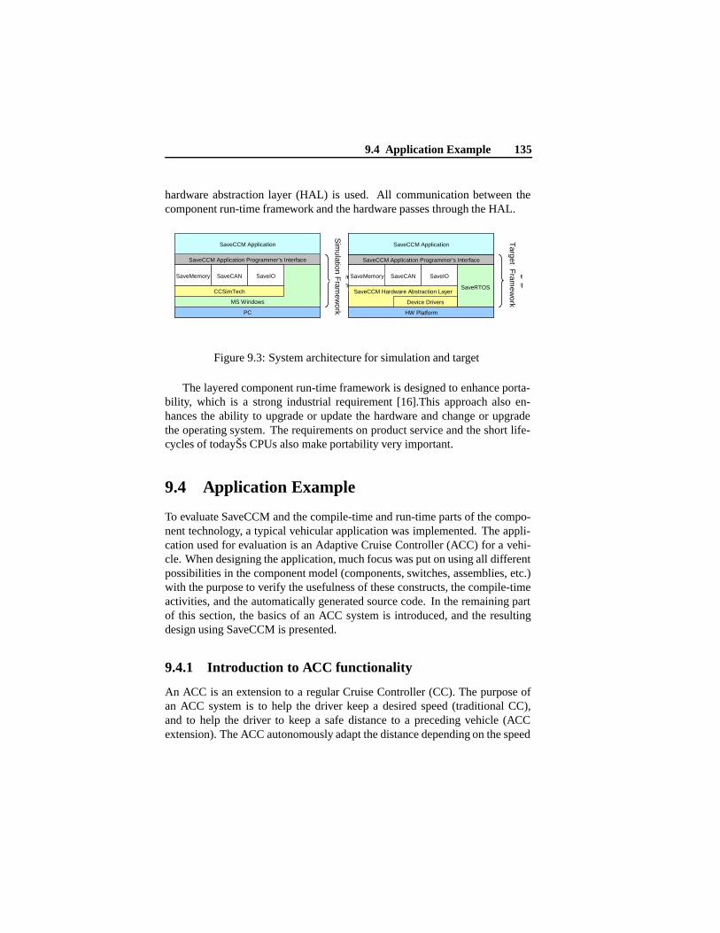
9.4 Application Example 135
hardware abstraction layer (HAL) is used. All communication between thecomponent run-time framework and the hardware passes through the HAL.
SaveCCM Application Programmer’s Interface
SaveCCM Application
MS Windows
SaveIO
PC
SaveMemory SaveCAN
CCSimTech
SaveCCM simulated run-timecomponent framework
SaveCCM Application Programmer’s Interface
SaveCCM Application
SaveCAN
SaveCCM Hardware Abstraction Layer
SaveIO
SaveRTOS
HW Platform
SaveMemory
Device Drivers
SaveCcomp
Sim
ulation Fram
ework
Target F
ramew
ork
SaveCCM Application Programmer’s Interface
SaveCCM Application
MS Windows
SaveIO
PC
SaveMemory SaveCAN
CCSimTech
SaveCCM simulated run-timecomponent framework
SaveCCM Application Programmer’s Interface
SaveCCM Application
SaveCAN
SaveCCM Hardware Abstraction Layer
SaveIO
SaveRTOS
HW Platform
SaveMemory
Device Drivers
SaveCcomp
Sim
ulation Fram
ework
Target F
ramew
ork
Figure 9.3: System architecture for simulation and target
The layered component run-time framework is designed to enhance porta-bility, which is a strong industrial requirement [16].This approach also en-hances the ability to upgrade or update the hardware and change or upgradethe operating system. The requirements on product service and the short life-cycles of todayŠs CPUs also make portability very important.
9.4 Application Example
To evaluate SaveCCM and the compile-time and run-time parts of the compo-nent technology, a typical vehicular application was implemented. The appli-cation used for evaluation is an Adaptive Cruise Controller (ACC) for a vehi-cle. When designing the application, much focus was put on using all differentpossibilities in the component model (components, switches, assemblies, etc.)with the purpose to verify the usefulness of these constructs, the compile-timeactivities, and the automatically generated source code. In the remaining partof this section, the basics of an ACC system is introduced, and the resultingdesign using SaveCCM is presented.
9.4.1 Introduction to ACC functionality
An ACC is an extension to a regular Cruise Controller (CC). The purpose ofan ACC system is to help the driver keep a desired speed (traditional CC),and to help the driver to keep a safe distance to a preceding vehicle (ACCextension). The ACC autonomously adapt the distance depending on the speed
136 Paper E
of the vehicle in front. The gap between two vehicles has to be large enough toavoid rear-end collisions.
To increase the complexity of a basic ACC system, and thereby exercisethe component model more, our ACC system has two non-standard functionalextensions. One extension is the possibility for autonomous changes of themaximum speed of the vehicle depending on the speed-limit regulations. Thisfeature would require actual speed-limit regulations to be known to the ACCsystem by, e.g., by using transmitters on the road signs or road map infor-mation in cooperation with a Global Positioning System (GPS). The secondextension is a brake-assist function, helping the driver with the braking proce-dure in extreme situations, e.g., when the vehicle in front suddenly brakes or ifan obstacle suddenly appears on the road.
9.4.2 Implementation using SaveCCM
On the top-level, we distinguish between three different sources of input tothe ACC application: (i) the Human Machine Interface (HMI) (e.g. desiredspeed and on/off status of the ACC system), (ii) the vehicular internal sensors(e.g. actual speed and throttle level), and, (iii) the vehicular external sensors(e.g. distance to the vehicle in front). The different outputs can be divided intwo categories, the HMI outputs (returning driver information about the systemstate), and the vehicular actuators for controlling the speed of the vehicle.
The application has two different trigger frequencies, 10 Hz and 50 Hz.Logging and HMI outputs activities execute with the lower rate, and controlrelated functionality at the higher rate.
Furthermore, there is a number of operational system modes identified, inwhich different components are active. The different modes are: Off, ACC En-abled and Brake Assist. Off is the initial system mode. In the Off mode, noneof the control related functionality is activated, but system-logging, function-ality related to determining distance to vehicles in front, and speed measuringare active. During the ACC enabled mode the control related functionality isactive. The controllers control the speed of the vehicle based on the parame-ters: desired speed, distance to vehicles in front, and speed-regulations. In theBrake Assist mode braking support for extreme situations is enabled.
The ACC system is implemented as an assembly (ACC Application in leftpart of Figure 9.4) built-up from four basic components, one switch, and onesub-assembly. The sub-assembly (ACC Controller) is in turn implemented asshown in Figure 9.4, right.
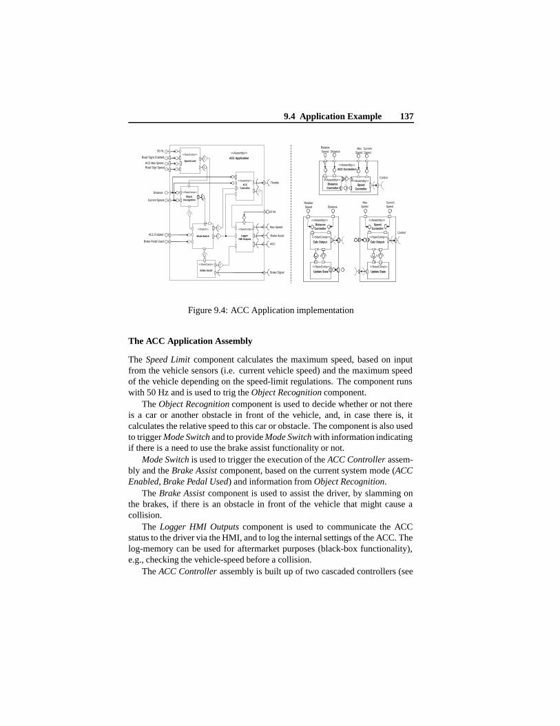
9.4 Application Example 137
<<Assembly>>ACC Controllers
<<Assembly>>Distance
Controller
<<Assembly>>Speed
Controller
Distance
Control
RelativeSpeed
MaxSpeed
<<Assembly>>Distance
Controller
<<SaveComp>>
Calc Output
<<SaveComp>>
Update State
<<Assembly>>Speed
Controller
<<SaveComp>>
Calc Output
<<SaveComp>>
Update State
DistanceRelativeSpeed
MaxSpeed
CurrentSpeed
CurrentSpeed
Control
Road Signs Enabled
Current Speed
Road Sign SpeedACC Max Speed
Distance
ACC Enabled
Brake Pedal Used
<<Assembly>>50 Hz
10 Hz
Brake Signal
Throttle
Brake Assist
<<SaveComp>>
Logger HMI Outputs
<<SaveComp>>
Object Recognition
<<SaveComp>>
Mode Switch
<<Switch>>
ACCController
<<Assembly>>
Brake Assist
ACC
Max Speed
ACC ApplicationSpeed Limit
<<SaveComp>>
Figure 9.4: ACC Application implementation
The ACC Application Assembly
The Speed Limit component calculates the maximum speed, based on inputfrom the vehicle sensors (i.e. current vehicle speed) and the maximum speedof the vehicle depending on the speed-limit regulations. The component runswith 50 Hz and is used to trig the Object Recognition component.
The Object Recognition component is used to decide whether or not thereis a car or another obstacle in front of the vehicle, and, in case there is, itcalculates the relative speed to this car or obstacle. The component is also usedto trigger Mode Switch and to provide Mode Switch with information indicatingif there is a need to use the brake assist functionality or not.
Mode Switch is used to trigger the execution of the ACC Controller assem-bly and the Brake Assist component, based on the current system mode (ACCEnabled, Brake Pedal Used) and information from Object Recognition.
The Brake Assist component is used to assist the driver, by slamming onthe brakes, if there is an obstacle in front of the vehicle that might cause acollision.
The Logger HMI Outputs component is used to communicate the ACCstatus to the driver via the HMI, and to log the internal settings of the ACC. Thelog-memory can be used for aftermarket purposes (black-box functionality),e.g., checking the vehicle-speed before a collision.
The ACC Controller assembly is built up of two cascaded controllers (see
138 Paper E
Figure 9.4, right), managing the throttle lever of the vehicle. This assemblyhas two sub-level assemblies, the Distance Controller assembly and the SpeedController assembly.
The reason for using a control feedback solution between the two con-trollers is that since the calculation is very time critical, it is important to de-liver the response (throttle lever level) as fast as possible. Hence, the controllersfirstly calculate their output values and after these values have been sent to theactuators, the internal state is updated (detailed presentation can be found in[6].
9.4.3 Application Test-Bed Environment
For the evaluation the RTXC operating system was used together with a CrossFIRE ECU7. RTXC is a pre-emptive multitasking operating system which per-mits a system to make efficient use of both time and system resources. RTXCis packaged as a set of C language source code files that needs to be compiledand linked with the object files of the application program.
The Cross FIRE is a C167-based8 IO-distributing ECU (Electronic ControlUnit) designed for CAN-based real-time systems. The ECU is developed andproduced by CC Systems, and intended for use on mobile applications in roughenvironments.
During functional testing and debugging, CC Systems use a simulation en-vironment called CCSimTech [15], which also was incorporated in this work.Developing and testing of distributed embedded systems is very challengingin their target environments, due to poor observability of application state andinternal behaviour. With CCSimTech, a complete system with several nodesand different types of interconnection media, can be developed and tested ona single PC without access to target hardware. This makes it possible to usestandard PC tools, e.g., for debugging, automated testing, fault injection, etc.
9.5 Evaluation and Discussion
CBSE addresses the whole life-cycle of software products. Thus, to fully eval-uate the suitability of a component technology requires experiences from usingthe technology in real projects (or at least in a pilot/evaluation project), by rep-
7CC Systems, Cross FIRE Electronic Control Unit, http://www.cc-systems.com8Infineon, C-167 processor, http://www.infineon.com
9.5 Evaluation and Discussion 139
resentatives from the intended organisation, using existing tools, processes andtechniques.
Our experiment was conducted using CC Systems’ tools and techniques,however we have not used the company’s development processes. Hence, wecan only give partial answers (indications) concerning the suitability our com-ponent technology.
We divide our evaluation in the following three categories:
Structural properties concerning the suitability of the imposed applicationstructure and architecture, and the ease to define and create the desiredbehaviour using the supported design patterns.
Behavioural properties concerning the application performance, in terms offunctional and non-functional behaviour.
Process properties concerning the ease and possibility to integrate the tech-nology with existing processes in the organisation.
The adaptive cruise controller application represents an advanced domainspecific function, which could have been ordered as a pilot study at the com-pany. The hardware, operating system, compilers, and the simulation tech-nique, have been selected among the companies repertoire, and are thus highlyrealistic.
The implementation of the application has not been done according to theprocess at the company, rather as an experiment by the authors. Thus, it ismainly the structural-, and behavioural related evaluation that can be addressedby our experience. However, to evaluate the process related issues, senior pro-cess managers at the company have helped to relate the component technologyto the processes.
The evaluation is conducted using a check-list assembled from require-ments for automotive component technologies by Möller et al. [16], risks withusing CBSE for embedded systems by Larn and Vickers [17], and from identi-fied needs, by Crnkovic [5].
9.5.1 Structural Properties
Based on the experiment performed we conclude that the component model issufficiently expressive for the studied application, and that it allows the soft-ware developer to focus on the core functionality when designing applications.The similarities with UML 2.0 provided important benefits by allowing us touse a slightly modified UML 2.0 editor for modelling applications. Also, issues
140 Paper E
related to task mapping, scheduling, and memory allocation are taken care ofby the compilations provided by the component technology. Further allowingthe developer to concentrate on application functionality.
Since the components have visible source code, and since all bindings be-tween components are automatically generated, making modifications of com-ponents is facilitated, though there is not yet any specific support to handlemaintenance implemented in the component technology.
It is straight forward to compile the ACC system for both Win32 on a reg-ular PC and RTXC on a Cross FIRE ECU. This is an indication of the portabil-ity of our technology across hardware platforms and operating systems. As aconsequence, components can be reused in different applications regardless ofwhich RTOS or hardware is used.
Configurability is essential for component reuse, e.g., within a Product LineArchitecture (PLA) [18]. In SaveCCM, components can be configured by staticbinding of values to ports. However, there is currently no explicit architec-tural element to specify this. In our experiment, we could however achieve thesame effect by directly editing the textual representation. For instance, a switchcondition can be set statically during design-time, and partially evaluated dur-ing compile-time, to represent a configuration in a PLA. A future extensionof SaveCCM is to add a new architectural element that makes it possible tovisualise and directly express static configurations of input ports. This willadditionally facilitate version and variant management.
9.5.2 Behavioural Properties
With respect to behavioural properties, our component technology is quite ef-ficient. The run-time framework provides a mapping to the used OS withoutadding functionality, and the compile-time mechanisms strive to achieve an ef-ficient application, by allocating several components to the same task. Somedata about our case-study:
• The compilation resulted in four tasks: one task including componentsspeed-limit, object recognition, and mode-switch; one task including log-ger HMI outputs; one task including brake assist; and one task includingthe four components in the ACC controller.
• The CPU utilisation in the different application modes are 7, 12, 15,perecents respectively for the off, brake assist, and ACC modes respec-tively.
9.6 Conclusions and Future Work 141
• The total application size is 114 kb, of which 104 kb belongs to the oper-ating system, and 10 kb to the application. The application part consistsof 2 kb of components code, together with 8 kb run-time framework andcompiler generated operating system dependent data and code.
To allow analysis it is essential to derive task level quality attributes fromthe corresponding component level attributes. In our case-study this was straight-forward, since the only quality attribute considered is worst-case executiontime, which can be straightforwardly composed by addition of the values asso-ciated to the components included in the task.
Furthermore, the CCSimTech simulation technique provided very usefulfor verification and debugging of the application functionality.
9.5.3 Process Related
The process related evaluation concerns the suitability to use the existing pro-cesses and organisation, when developing component-based applications. Soprocess related issues are not directly addressable by our experiment, based ona set of interviews company engineers have expressed the following:
• The RTOS and platform independence is a major advantage of the ap-proach.
• The integration with the simulation technique, CCSimTech, used in prac-tically all development projects at CC Systems, will substantially facili-tate the integration of SaveCCM in the development process.
• The tools included in the component technology, as well as the user-documentation, have not reached an acceptable level of quality for usein real industry projects.
• The maintainability aspects of CBD are attractive, since changes are sim-plified by the tight relation between the applications description and thesource code.
9.6 Conclusions and Future Work
We have described the initial implementation of our component technology forvehicular systems, and evaluated it in an industrial environment, using require-ments and needs identified in related research.
142 Paper E
The evaluation shows that the existing parts of the component technologymeet the requirements and needs related to them. However, to meet overallrequirements and needs, extensions to the technology are needed.
Plans for future work include extending the component technology withsupport for multiple nodes, integration of legacy-code with the components[19], run-time monitoring support [20], and a real-time database for structuredhandling of shared data [21]. Implementation of more types of automated anal-ysis to prove the concept of determining system attributes from componentattributes is also a target for future work. However, there is also a need formethods to determine component attributes. Furthermore, to make the pro-totype useful in practice, there are needs for integrating our technology withsupporting tools, e.g., automatic generation of XML descriptions from UML2.0 drawings, and connectivity with configuration management tools.
An indication of the potential of our component technology, and CBSE forembedded systems development in general, is that the company involved inthe case-study finds our technology promising and has expressed interest tocontinue the cooperation.
AcknowledgementsWe would like to thank CC Systems for inviting and helping us to realise this
pilot project. Special thanks to Jörgen Hansson and Ken Lindfors for invitationand to Johan Strandberg and Fredrik Löwenhielm for their support with allkinds of technical issues. We would also like to thank Sasikumar Punnekkatfor valuable feedback on early versions of this article.
Bibliography
[1] K.L. Lundbäck and J. Lundbäck and M. Lindberg. Component-BasedDevelopment of Dependable Real-Time Applications. Arcticus Systems:http://www.arcticus.se (Last Accessed: 2005-01-18).
[2] R. van Ommering et al. The Koala Component Model for ConsumerElectronics Software. IEEE Computer, 33(3):78–85, March 2000.
[3] M. de Jonge, J. Muskens, and M. Chaudron. Scenario-Based Prediction ofRun-Time Resource Consupmption in Component-Based Software Sys-tems. In Proceedings of the 6th International Workshop on Component-Based Software Engineering, May 2003.
[4] K. C. Wallnau. Volume III: A Component Technology for PredictableAssembly from Certifiable Components. Technical report, Software En-gineering Institute, Carnegie Mellon University, April 2003.
[5] I. Crnkovic. Componet-Based Approach for Embedded Systems. InProceedings of 9th International Workshop on Component-Oriented Pro-gramming, June 2004.
[6] M. Åkerholm, A. Möller, H. Hansson, and M. Nolin. SaveComp - aDependable Component Technology for Embedded Systems Software.Technical report, MRTC Report ISSN 1404-3041 ISRN MDH-MRTC-165/2004-1-SE, MRTC, Mälardalen University, December 2004.
[7] H. Hansson, M. Åkerholm, I. Crnkovic, and M. Törngren. SaveCCM -a Component Model for Safety-Critical Real-Time Systems. In Proceed-ings of 30th Euromicro Conference, Special Session Component Modelsfor Dependable Systems, September 2004.
143
144 Bibliography
[8] K. Sandström, J. Fredriksson, and M. Åkerholm. Introducing a Com-ponent Technology for Safety Critical Embedded Real-Time Systems.In Proceedings of th 7th International Symposium on Component-BasedSoftware Engineering (CBSE7), May 2004.
[9] M. Shaw and D. Garlan. Software Architecture: Perspectives on anEmerging Discipline. Prentice Hall; 1 edition, 1996. ISBN 0-131-82957-2.
[10] G.C. Butazzo. Hard Real-Time. Kluwer Academic Publishers, 1997.ISBN: 0-7923-9994-3.
[11] A.V. Fioukov, E.M. Eskenazi, D.K. Hammer, and M. Chaudron. Evalua-tion of Static Properties for Component-Based Architetures. In Proceed-ings of 28th Euromicro Conference, September 2002.
[12] H.W. Schmidt and R.H. Reussner. Parameterized Contracts and AdapterSynthesis. In Proceedings of the 5th ICSE Workshop on Component-Based Software Engineering, May 2001.
[13] D.H. Stamatis. Failure Mode and Effect Analysis: FMEA from Theory toExecution. ASQ Quality Press, 2nd Edition, 2003. ISBN 0-87389598-3.
[14] M.G. Harbour, M.H. Klein, and J.P. Lehoczky. Timing analysis for Fixed-Priority Scheduling of Hard Real-Time Systsems. IEEE Transactions,20(1), January 1994.
[15] A. Möller and P. Åberg. A Simulation Technology for CAN-based Sys-tems. CAN Newsletter, 4, December 2004.
[16] A. Möller, J. Fröberg, and M. Nolin. Industrial Requirements on Com-ponent Technologies for Embedded Systems. In Proceedings of the 7thInternational Symposium on Component-Based Software Engineering.2004 Proceedings Series: Lecture Notes in Computer Science, Vol. 3054,May 2004.
[17] W. Lam and A.J. Vickers. Managing the Risks of Component-Based Soft-ware Engineering. In Proceedings of the 5th International Symposium onAssessment of Software Tools, June 1997.
[18] P. Clements and L. Northrop. Software Product Lines: Practices andPatterns. Addison-Wesley, 2001. ISBN 0-201-70332-7.
[19] M. Åkerholm, K. Sandström, and J. Fredriksson. Interference Con-trol for Integration of Vehicular Software Components. Technical re-port, MRTC Report ISSN 1404-3041 ISRN MDH-MRTC-162/2004-1-SE, MRTC, Mälardalen University, May 2004.
[20] D. Sundmark, A. Möller, and M. Nolin. Monitored Software Compo-nents – A Novel Software Engineering Approach –. In Proceedings of the11th Asia-Pasific Software Engineering Conference, Workshop on Soft-ware Architectures and Component Technologies, November 2004.
[21] D. Nyström. COMET: A Component-Based Real-Time Database for Ve-hicle Control Systems. Technical report, Technology Licentiate ThesisNo.26, ISSN 1651-9256, ISBN 91-88834-41-7, Mälardalen Real-TimeReseach Centre, Mälardalen University, May 2003.


![VEHICLE COMPONENT APPLICATIONS · D4 VEHICLE COMPONENT APPLICATIONS - INDEX AUDI CONT. 200 Turbo 10.83 09.86 JY K-Jetronic 5 2.1L D41 08.85 12.91 MC K-Jetronic [Lambda] 5 2.2L D41](https://img.pdfslide.us/doc/110x75/6021f73ca6d11b4e4d0f339f/vehicle-component-applications-d4-vehicle-component-applications-index-audi-cont.jpg)