Embed Size (px)
Citation preview
See discussions, stats, and author profiles for this publication at: https://www.researchgate.net/publication/270460408
Component sensitivity analysis of conceptual vehicle body for lightweight
design under static and dynamic stiffness demands
Article in International Journal of Vehicle Design · January 2014
DOI: 10.1504/IJVD.2014.064546
CITATIONS
15
2 authors, including:
Some of the authors of this publication are also working on these related projects:
Educational finite element software View project
Automobile Body Design and Optimization View project
Wenjie Zuo
Jilin University
31 PUBLICATIONS 313 CITATIONS
SEE PROFILE
All content following this page was uploaded by Wenjie Zuo on 27 January 2015.
The user has requested enhancement of the downloaded file.
Int. J. Vehicle Design, Vol. 66, No. 2, 2014 107
Copyright © 2014 Inderscience Enterprises Ltd.
Component sensitivity analysis of conceptual vehicle body for lightweight design under static and dynamic stiffness demands
Wei Chen and Wenjie Zuo* State Key Laboratory of Automotive Simulation and Control, Jilin University, Changchun 130025, China
and
College of Mechanical Science and Engineering, Jilin University, Changchun 130025, China E-mail: [email protected] E-mail: [email protected] *Corresponding author
Abstract: At conceptual design stage, engineers mostly rely on their experience, intuition, and data accumulation when making decisions on conceptual vehicle body (CVB). This paper presents a component sensitivity method for the lightweight design of the CVB. Firstly, CVB is simplified as a frame structure consisting of box beams. Secondly, torsional stiffness, bending stiffness and frequencies are adopted to evaluate the global stiffness performances of the CVB frame. Thirdly, component sensitivity formulas are derived. Fourthly, two application examples of car and bus frame verify that the proposed method is efficient to guide the cross-sectional sizes modification. The sufficient condition to obtain positive frequency sensitivity is also discussed. And finally Vehicle Body-FDO software is released for free to implement this method.
Keywords: vehicle design; CVB; conceptual vehicle body; lightweight; sensitivity analysis; structural components; torsional and bending stiffness; frequency; box beam.
Reference to this paper should be made as follows: Chen, W. and Zuo, W. (2014) ‘Component sensitivity analysis of conceptual vehicle body for lightweight design under static and dynamic stiffness demands’, Int. J. Vehicle Design, Vol. 66, No. 2, pp.107–123.
Biographical notes: Wei Chen is a Master Degree candidate, majored in solid mechanics, Jilin University, China.
Wenjie Zuo received his BS, MS and PhD from Jilin University in 2005, 2007 and 2010, respectively. He is currently an Associate Professor in Jilin University. His research fields include vehicle lightweight design and CAE software development.
108 W. Chen and W. Zuo
1 Introduction
The modern vehicle body design process can generally be divided into two stages: the conceptual design and the detailed design. The conceptual vehicle body (CVB) currently concentrates on its specific merits to afford the early stage predictions about the global performances of mass, stiffness and strength for simplified body-in-white (BIW) structure. In practice, design engineers mostly rely on their experience, intuition, data accumulation or benchmarking, when making decisions on the CVB. If more performances of the CVB could be determined by refined analysis or optimisation methods at this stage, the subsequent design risk can be controlled or reduced. To date, the subject of the CVB design and optimisation has achieved some advancements.
The simplified designs of the CVB are as follows. Dynamic design of the bus body frame was carried out using numerical method even in the initial designing phase (Gombor, 2005). Mundo et al. (2011) proposed a method for the concept design of vehicle bodies, using the reduced models of joints, beams and panels. Then, a series of special finite element (FE) software was developed to build this simplified CVB. For example, one vehicle design system was implemented to rapidly estimate the structural property at the conceptual design stage (Hou et al., 2011). In succession, the other engineering software for the BIW structure with semi-rigid beams was programmed in .NET framework (Zuo et al., 2012). Above all, thin-walled box beams were extensively and conveniently used to create the CVB frame. Each box beam has three design variables, i.e. breadth, height and thickness to define the cross-sectional shape. During the design process, the most important issue is how to modify the initial CVB frame to improve its stiffness and reduce its mass, but the solution of this problem depends on structural sensitivity analysis.
Some procedures were attempted to obtain the lightweight and high-stiffness CVB. Genetic algorithms (GA) were used to optimise a real bus structure under the torsional stiffness demand (Gauchia et al., 2010). However, this research did not make use of the sensitivity information, so GA was inefficient in bus structural optimisation. Furthermore, gradient-based sensitivity analysis was adopted to speed up the CVB optimisation. A fast sensitivity approach was proposed to analyse and optimise the bending and torsion modes of a CVB (Donders et al., 2009). Gauge sensitivity for assessing vehicle body structural stiffness is investigated (Zhang and Prater, 2011). Single-product optimisation to a whole family of products was extended, where direct sensitivity analysis was introduced (Torstenfelt and Klarbring, 2006, 2007).
Previous sensitivity analysis has mostly focused only on the stiffness with respect to size design variables and little attention has been paid to the sensitivity analysis of the stiffness with respect to mass. The former is only used to improve the stiffness, but not meanwhile reduce the mass. However, the latter is effective to not only improve the stiffness but also reduce the mass. In addition, component system design and analysis has been proposed to include more engineering demands (Xia et al., 2012a, 2012b; Zhu et al., 2009). In the engineering practice, box beams with identical cross-sectional sizes are organised as a component. For example, owing to the geometric symmetry of the CVB, box beams in the symmetric position must be in a unique component.
Consequently, the innovation about the presented method is the component sensitivity analysis of the CVB for lightweight design under the stiffness demands. This innovative sensitivity analysis method can direct the modification of the CVB frame.
Component sensitivity analysis of conceptual vehicle body 109
The method proposed in this paper fulfils these needs. The outline of this paper is organised as follows:
1 Introduction
2 CVB FE modelling
3 Evaluation indexes of global performances
4 Component sensitivity analysis
5 The development of vehicle body-FDO software
6 Application examples
7 Discussion for the negative sensitivity
8 Conclusion.
2 FE modelling for CVB consisting of box beam elements
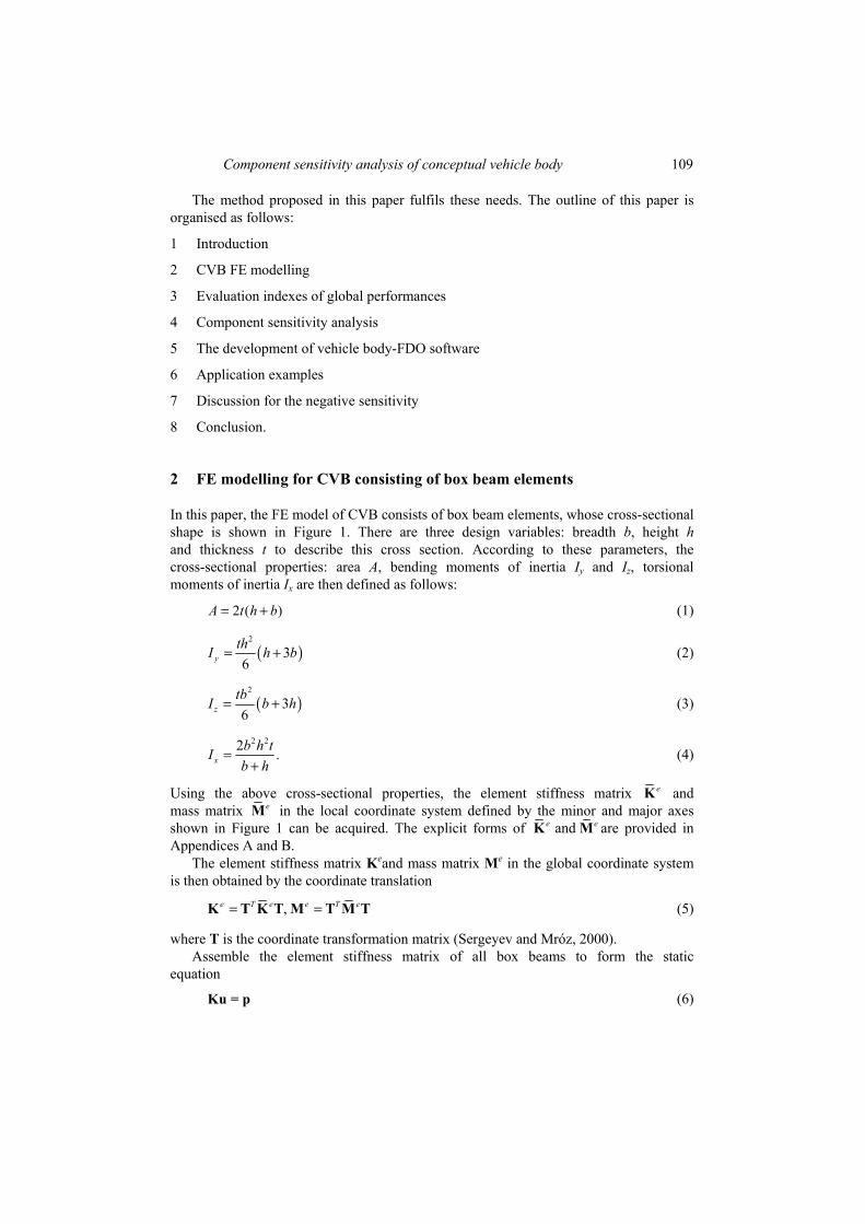
In this paper, the FE model of CVB consists of box beam elements, whose cross-sectional shape is shown in Figure 1. There are three design variables: breadth b, height h and thickness t to describe this cross section. According to these parameters, the cross-sectional properties: area A, bending moments of inertia Iy and Iz, torsional moments of inertia Ix are then defined as follows:
2 ( )A t h b= + (1)
( )2
36y
thI h b= + (2)
( )2
36z
tbI b h= + (3)
2 22 .xb h tIb h
=+
(4)
Using the above cross-sectional properties, the element stiffness matrix eK and mass matrix eM in the local coordinate system defined by the minor and major axes shown in Figure 1 can be acquired. The explicit forms of ande eK M are provided in Appendices A and B.
The element stiffness matrix Keand mass matrix Me in the global coordinate system is then obtained by the coordinate translation
,e T e e T e= =K T K T M T M T (5)
where T is the coordinate transformation matrix (Sergeyev and Mróz, 2000). Assemble the element stiffness matrix of all box beams to form the static
equation
Ku = p (6)
110 W. Chen and W. Zuo
where K is the global stiffness matrix and 1
,en ei ei
n=
=∑K K is the number of beam elements; u is the displacement vector, caused by force vector p. As above, assemble the element mass matrix of all box beams and combine the global stiffness matrix to form the dynamic equation
2( ) for 1, ,i i i mω− = = …K M u 0 (7)
where M is the global mass matrix; ωi and ui are, respectively, the ith angle frequency and mode shape; m is the number of specified vibration mode. In the following, the evaluation indexes of global performances are defined to simulate the loads and constraints of the CVB.
Figure 1 Thin-walled box cross section and its local coordinates (see online version for colours)
3 Static and dynamic stiffness definition for CVB
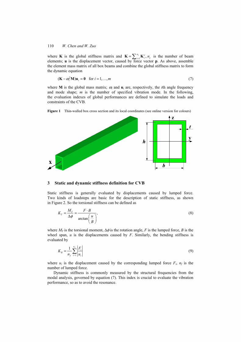
Static stiffness is generally evaluated by displacements caused by lumped force. Two kinds of loadsteps are basic for the description of static stiffness, as shown in Figure 2. So the torsional stiffness can be defined as
,arctan
TT
M F BKuB
φ⋅= =
∆
(8)
where MT is the torsional moment, ∆φ is the rotation angle, F is the lumped force, B is the wheel span, u is the displacements caused by F. Similarly, the bending stiffness is evaluated by
=1
1 fni
Bif i
FK
n u= ∑ (9)
where ui is the displacement caused by the corresponding lumped force Fi, nf is the number of lumped force.
Dynamic stiffness is commonly measured by the structural frequencies from the modal analysis, governed by equation (7). This index is crucial to evaluate the vibration performance, so as to avoid the resonance.
Component sensitivity analysis of conceptual vehicle body 111
After finishing the definition of static and dynamic stiffness, the component sensitivity information of those with respect to the cross-sectional design variables is investigated in the following section. In order to clarify the presentation, we inversely derive the sensitivity expressions.
Figure 2 Sketch for torsional and bending loadsteps: (a) torsional loadstep and (b) bending loadstep (see online version for colours)
(a) (b)
4 Component sensitivity analysis of static and dynamic stiffness
In the CVB design process, beam elements with the same box section are classified into the unique component. Therefore, a component associates a cross-sectional design variables group: breadth b, height h and thickness t. Torsional stiffness KT, bending stiffness KB, frequencies ωi and structural total mass M is implicit function of cross-sectional design variables, i.e.,
= ( ), = ( ), = ( ), = ( )T T B B i iK K K K M Mω ωx x x x (10)
where x = [b1, h1, t1, …, bj, hj, tj, …, bn, hn, tn], n is the number of components.
4.1 Static sensitivity analysis of torsional stiffness
For the sake of lightweight objective, torsional stiffness sensitivity is defined as the differentiation with respect to total mass, and then numerator and denominator divide ∂xk, respectively, as follows
k T kTT
k
K xKSM M x
∂ ∂∂= =
∂ ∂ ∂ (11)
where kTS is the sensitivity of torsional stiffness with respect to the mass, connected by
the kth design variable, where k ∈ [1, 2, 3, …, 3 × n]. Now taking the derivative of equation (8), we obtain
2 2.
arctan 1
T z
k k
K F ux xu u
B B
∂ ∂= −∂ ∂ +
(12)
112 W. Chen and W. Zuo
Structural mass of the CVB is the sum of all components and may be written as
1 1 1 1 1
c c k c kn n n n ne
k j j j jk k j k j
M m m l Aρ= = = = =
= = =∑ ∑∑ ∑∑ (13)
where mk is the kth component mass; nc is the number of components; nk is the number of box beams in the kth component; e
jm is the mass of the jth element in the kth component; ρj, lj, Aj are the density, length, cross-sectional area of the jth box beam in the kth component. Because the mass of each component is independent of the design variables in other component, the derivatives of mass M with respect to design variable xk is expressed
1 11
1
.k kc
kn nn e n
j j j jk j j jk kj j
jk k k k k k
m l Am AmM lx x x x x x
ρρ= ==
=
∂ ∂∂ ∂∂∂ = = = = =∂ ∂ ∂ ∂ ∂ ∂
∑ ∑∑ ∑ (14)
In the following, the most important issue is to obtain the displacement sensitivity with respect to design variable xk, namely ∂u/∂xk. There are two kinds of analytical sensitivity analysis approaches: direct method and adjoint method (Zhou et al., 2000). When there is a large number of design variables and a small number of responses, it is usually sensible to use the adjoint method for sensitivity analysis. On the contrary, the direct method should be used (Zhou et al., 2000).
In the CVB engineering, there are five responses: torsional stiffness, bending stiffness and the first several frequencies, which often need be controlled or improved. However, cross-sectional styles may reach to 10 or more, i.e. 30 or more design variables. As a result, adjoint sensitivity method should be introduced to obtain the displacement sensitivity.
Take equation (6) derivative with respect to design variable xk
0.k kx x
∂ ∂+ =∂ ∂K uu K (15)
The sensitivity of the displacement vector u is calculated as
1 .k kx x
−∂ ∂= −∂ ∂
u KK u (16)
If equation (16) is adopted to calculate gradient, then the largest cost is the forward and backward substitution for the calculation of the derivative of the displacement vector with respect to the design variable, which is called the direct method. Equation (16) obtain the displacement vector sensitivity, but torsional loadstep only need the sensitivity information of one displacement component, which is caused by the lumped force in Figure 2(a). For the adjoint sensitivity analysis, the ith displacement is described as the function of the displacement vector u
Ti iu = Q u (17)
where Qi is the adjoint load vector, whose the ith element is one, and others are all zero, thus
[ ]0,0, ,0,1,0, ,0,0 .Ti =Q (18)
Component sensitivity analysis of conceptual vehicle body 113
The sensitivity of response ui with respect to design variable xk is calculated as T
Ti ii
k k k
ux x x
∂ ∂ ∂= +∂ ∂ ∂
Q uu Q (19)
Qi is a constant vector, so
0.Ti kx∂ ∂ =Q (20)
Substituting equations (16) and (20) into equation (19), we obtain
, Tii i i
k k
ux x
∂ ∂= − =∂ ∂
Ku u Ku Q (21)
where iu is adjoint displacement vector. The number of adjoint displacement and load are irrelevant to the number of design variables and only depend on the number of responses. Thereby, adjoint sensitivity method can reduce the computational cost of torsional stiffness response.
Sensitivity of global stiffness matrix K with respect to design variable xk is determined by
1 1 1 1 1
.c k c k ke T e en n n n n
Ti i i
k i k i ik k k kx x x x= = = = =
∂ ∂ ∂∂ = = =∂ ∂ ∂ ∂∑∑ ∑∑ ∑K T K T KK T T (22)
Local stiffness matrix eiK is attached in Appendix A. Derivative of compound function
is introduced to calculated the sensitivity of eiK
.e e e e e
yi i i x i i z
k k x k y k z k
II IAx A x I x I x I x
∂∂ ∂ ∂ ∂ ∂ ∂ ∂∂= + + +∂ ∂ ∂ ∂ ∂ ∂ ∂ ∂ ∂K K K K K (23)
Now taking the derivative of equations (1)–(4), we obtain the cross-sectional properties sensitivity with respect to design variable, as follows.
If the design variable xk is cross-sectional breadth b, then 2 2 2
2
2 ( 2 )2 , , , .2 2( )
yx zII IA h tb b h th tbt thbb b b bb h
∂∂ ∂∂ += = = = +∂ ∂ ∂ ∂+
(24)
If the design variable xk is cross-sectional height h, then 2 2 2
2
2 ( 2 )2 , , , .2 2( )
yx zII IA b th h b th tbt tbhh h h hb h
∂∂ ∂∂ += = = + =∂ ∂ ∂ ∂+
(25)
Else if the design variable xk is cross-sectional thickness t, then 2 2 2 222( ), , ( 3 ), ( 3 ).
6 6yx zII IA b h h bh b h b b h
t t b h t t∂∂ ∂∂ = + = = + = +
∂ ∂ + ∂ ∂ (26)
Finally, substituting equations (12), (14), (21), (22)–(26) into equation (11), the torsional stiffness sensitivity analysis is finished.
114 W. Chen and W. Zuo
4.2 Static sensitivity analysis of bending stiffness
Being similar to the torsional stiffness sensitivity, the sensitivity of the bending stiffness with respect to the mass, connected by the kth design variable, is defined as
.k B kBB
k
K xKSM M x
∂ ∂∂= =
∂ ∂ ∂ (27)
By the direct differentiation, we obtain the sensitivity of the bending stiffness from equation (9)
2=1
1 .( )
fni iB
ik f ki
F uKx n xu
∂∂ = −∂ ∂∑ (28)
Substituting equations (14), (21), (22)–(26) and (28) into equation (27), the bending stiffness sensitivity analysis is also fulfilled.
4.3 Dynamic sensitivity analysis of frequencies
The state of free vibrations is governed by the eigenvalue equation 2( ) .i iω− =K M u 0 (29)
The eigenvectors ui are all M-normalised, so that
1.Ti i =u Mu (30)
Assuming that ωi are simple, the frequency sensitivities are obtained from equation (29) by direct differentiation with respect to design variable xk
2 22 ( ) .i ii i i i
k k k kx x x xωω ω ω
∂ ∂∂ ∂− − + − = ∂ ∂ ∂ ∂
uK MM u K M 0 (31)
By premultiplying equation (31) by Tiu and employing equation (30), the following
expression is obtained for the frequency sensitivity
21 .2
Tii i i
k i k kx x xω ω
ω ∂ ∂ ∂= − ∂ ∂ ∂
K Mu u (32)
Then, equation (32) is expanded in the component level
2 2
1 1 1
1 1 .2 2
c k ke e e en n nT Tj j j je e e ei
i i i i i ik j jk i k k i k kx x x x x
ω ω ωω ω= = =
∂ ∂ ∂ ∂∂= − = − ∂ ∂ ∂ ∂ ∂ ∑∑ ∑
K M K Mu u u u (33)
The sensitivity of element mass matrix in global coordinate with respect to design variable xk is expressed as
( ) .e ej je T e
k kx x∂ ∂
=∂ ∂M M
T T (34)
Component sensitivity analysis of conceptual vehicle body 115
By the explicit differentiation, we get
.e e e e ej j j j y jx z
k k x k y k z k
II IAx A x I x I x I x
∂ ∂ ∂ ∂ ∂ ∂∂ ∂∂= + + +∂ ∂ ∂ ∂ ∂ ∂ ∂ ∂ ∂M M M M M
(35)
In sum, substituting equations (22)–(26), (34) and (35) into equation (33), the task of frequency sensitivities is completed.
5 The development of vehicle body-FDO software
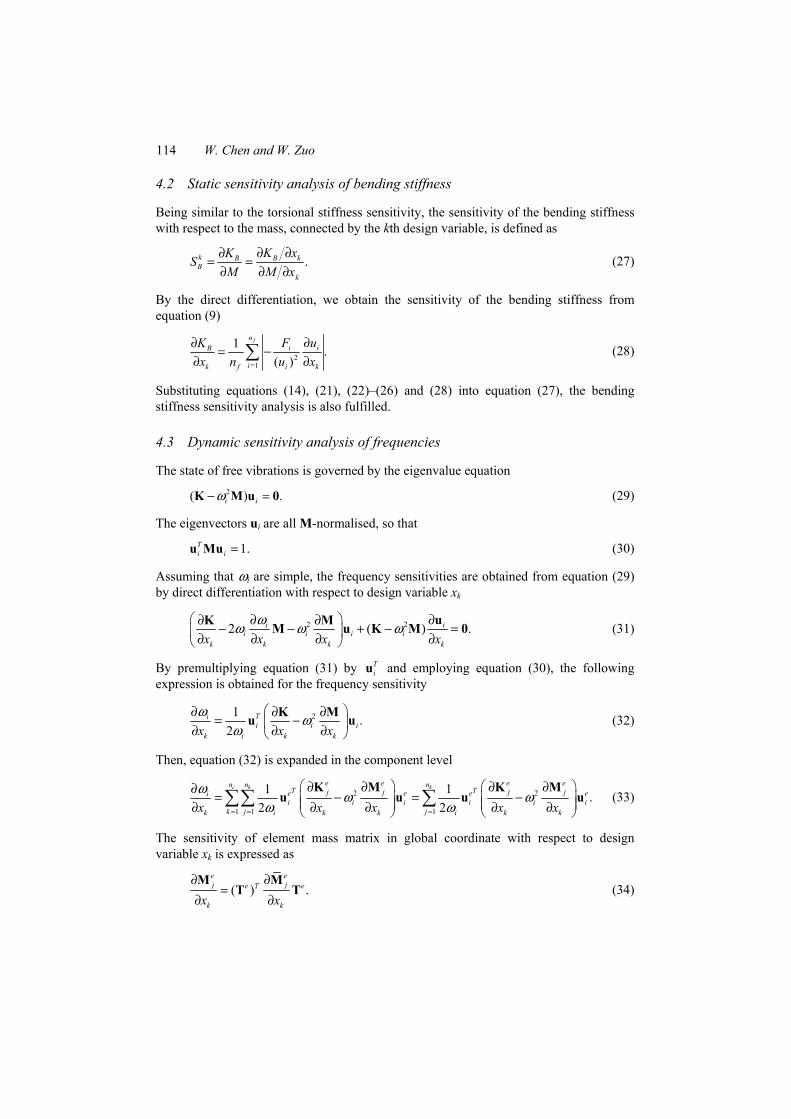
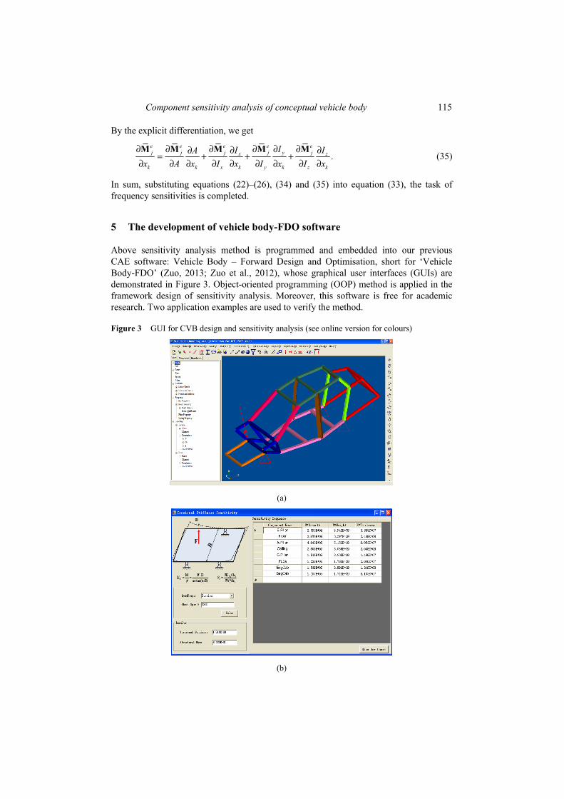
Above sensitivity analysis method is programmed and embedded into our previous CAE software: Vehicle Body – Forward Design and Optimisation, short for ‘Vehicle Body-FDO’ (Zuo, 2013; Zuo et al., 2012), whose graphical user interfaces (GUIs) are demonstrated in Figure 3. Object-oriented programming (OOP) method is applied in the framework design of sensitivity analysis. Moreover, this software is free for academic research. Two application examples are used to verify the method.
Figure 3 GUI for CVB design and sensitivity analysis (see online version for colours)
(a)
(b)
116 W. Chen and W. Zuo
6 Application examples
The design objectives of the two cases are to increase the torsional stiffness, bending stiffness, vibration frequencies and meanwhile to decrease the mass of the CVB frame. These design objectives are achieved by the sizes modification of the CVB frame using the results of the corresponding sensitivity analysis. Mild steel is used for this two cases, whose elastic modulus, Poisson’s ratio and density are 2.05 × 10⁵ MPa, 0.27 and 7.8e–9 ton/mm3, respectively.
6.1 Car frame
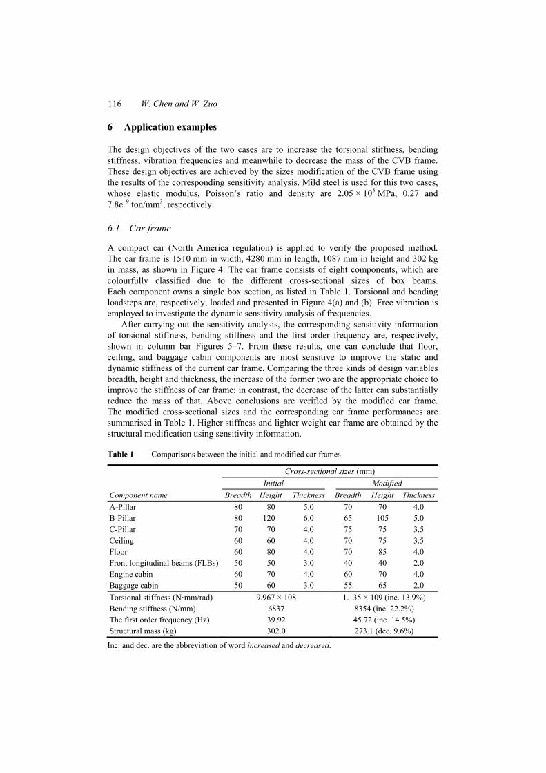
A compact car (North America regulation) is applied to verify the proposed method. The car frame is 1510 mm in width, 4280 mm in length, 1087 mm in height and 302 kg in mass, as shown in Figure 4. The car frame consists of eight components, which are colourfully classified due to the different cross-sectional sizes of box beams. Each component owns a single box section, as listed in Table 1. Torsional and bending loadsteps are, respectively, loaded and presented in Figure 4(a) and (b). Free vibration is employed to investigate the dynamic sensitivity analysis of frequencies.
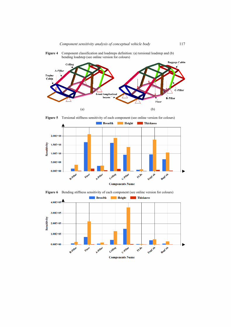
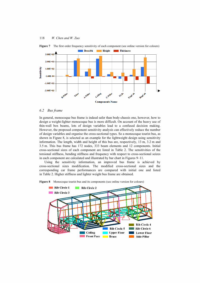
After carrying out the sensitivity analysis, the corresponding sensitivity information of torsional stiffness, bending stiffness and the first order frequency are, respectively, shown in column bar Figures 5–7. From these results, one can conclude that floor, ceiling, and baggage cabin components are most sensitive to improve the static and dynamic stiffness of the current car frame. Comparing the three kinds of design variables breadth, height and thickness, the increase of the former two are the appropriate choice to improve the stiffness of car frame; in contrast, the decrease of the latter can substantially reduce the mass of that. Above conclusions are verified by the modified car frame. The modified cross-sectional sizes and the corresponding car frame performances are summarised in Table 1. Higher stiffness and lighter weight car frame are obtained by the structural modification using sensitivity information.
Table 1 Comparisons between the initial and modified car frames
Component name
Cross-sectional sizes (mm) Initial Modified
Breadth Height Thickness Breadth Height Thickness A-Pillar 80 80 5.0 70 70 4.0 B-Pillar 80 120 6.0 65 105 5.0 C-Pillar 70 70 4.0 75 75 3.5 Ceiling 60 60 4.0 70 75 3.5 Floor 60 80 4.0 70 85 4.0 Front longitudinal beams (FLBs) 50 50 3.0 40 40 2.0 Engine cabin 60 70 4.0 60 70 4.0 Baggage cabin 50 60 3.0 55 65 2.0 Torsional stiffness (N·mm/rad) 9.967 × 10⁸ 1.135 × 10⁹ (inc. 13.9%) Bending stiffness (N/mm) 6837 8354 (inc. 22.2%) The first order frequency (Hz) 39.92 45.72 (inc. 14.5%) Structural mass (kg) 302.0 273.1 (dec. 9.6%)
Inc. and dec. are the abbreviation of word increased and decreased.
Component sensitivity analysis of conceptual vehicle body 117
Figure 4 Component classification and loadsteps definition: (a) torsional loadstep and (b) bending loadstep (see online version for colours)
(a) (b)
Figure 5 Torsional stiffness sensitivity of each component (see online version for colours)
Figure 6 Bending stiffness sensitivity of each component (see online version for colours)
118 W. Chen and W. Zuo
Figure 7 The first order frequency sensitivity of each component (see online version for colours)
6.2 Bus frame
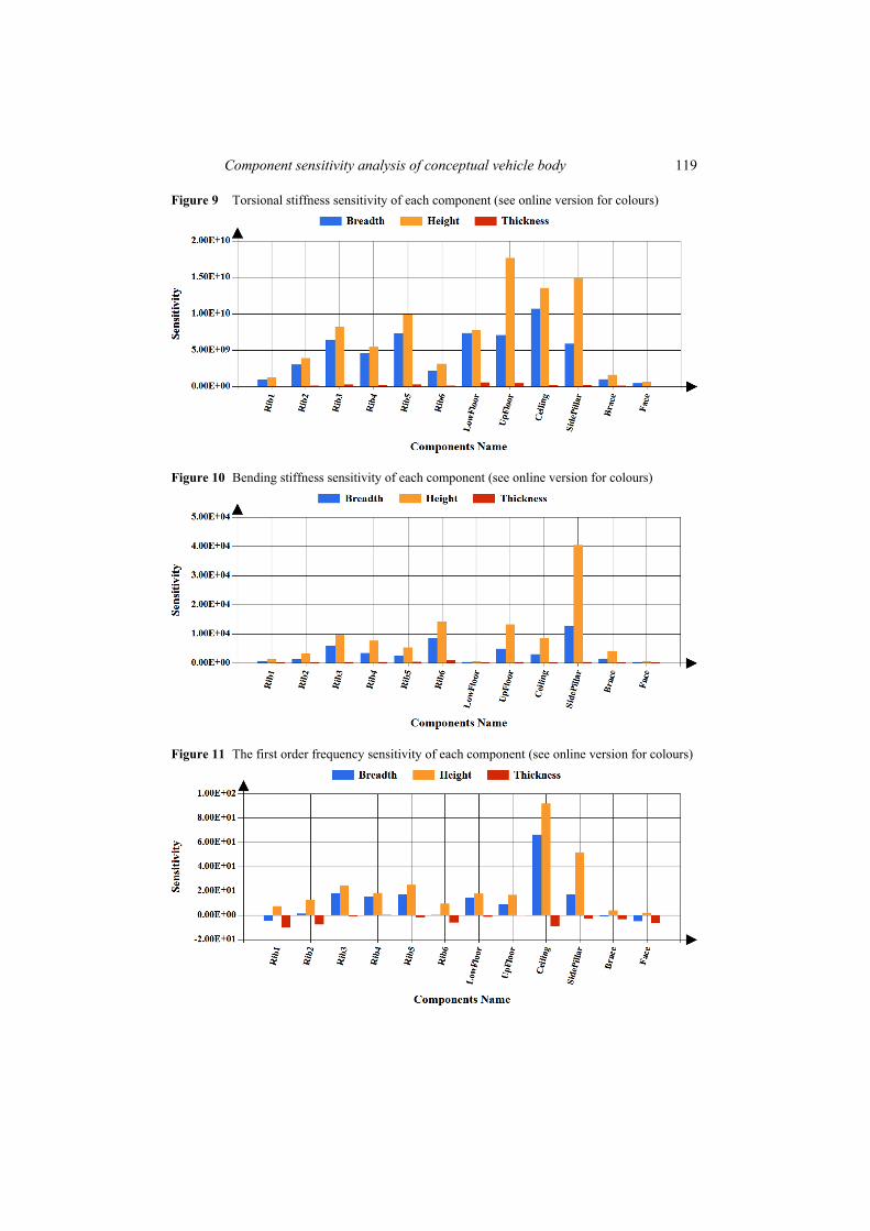
In general, monocoque bus frame is indeed safer than body-chassis one, however, how to design a weight-lighter monocoque bus is more difficult. On account of the heavy use of thin-wall box beams, lots of design variables lead to a confused decision making. However, the proposed component sensitivity analysis can effectively reduce the number of design variables and organise the cross-sectional types. So a monocoque tourist bus, as shown in Figure 8, is selected as an example for the lightweight design using sensitivity information. The length, width and height of this bus are, respectively, 13 m, 3.2 m and 3.5 m. This bus frame has 172 nodes, 333 beam elements and 12 components. Initial cross-sectional sizes of each component are listed in Table 2. The sensitivities of the torsional stiffness, bending stiffness and frequency with respect to cross-sectional seizes in each component are calculated and illustrated by bar chart in Figures 9–11.
Using the sensitivity information, an improved bus frame is achieved by cross-sectional sizes modification. The modified cross-sectional sizes and the corresponding car frame performances are compared with initial one and listed in Table 2. Higher stiffness and lighter weight bus frame are obtained.
Figure 8 Monocoque tourist bus and its components (see online version for colours)
Component sensitivity analysis of conceptual vehicle body 119
Figure 9 Torsional stiffness sensitivity of each component (see online version for colours)
Figure 10 Bending stiffness sensitivity of each component (see online version for colours)
Figure 11 The first order frequency sensitivity of each component (see online version for colours)
120 W. Chen and W. Zuo
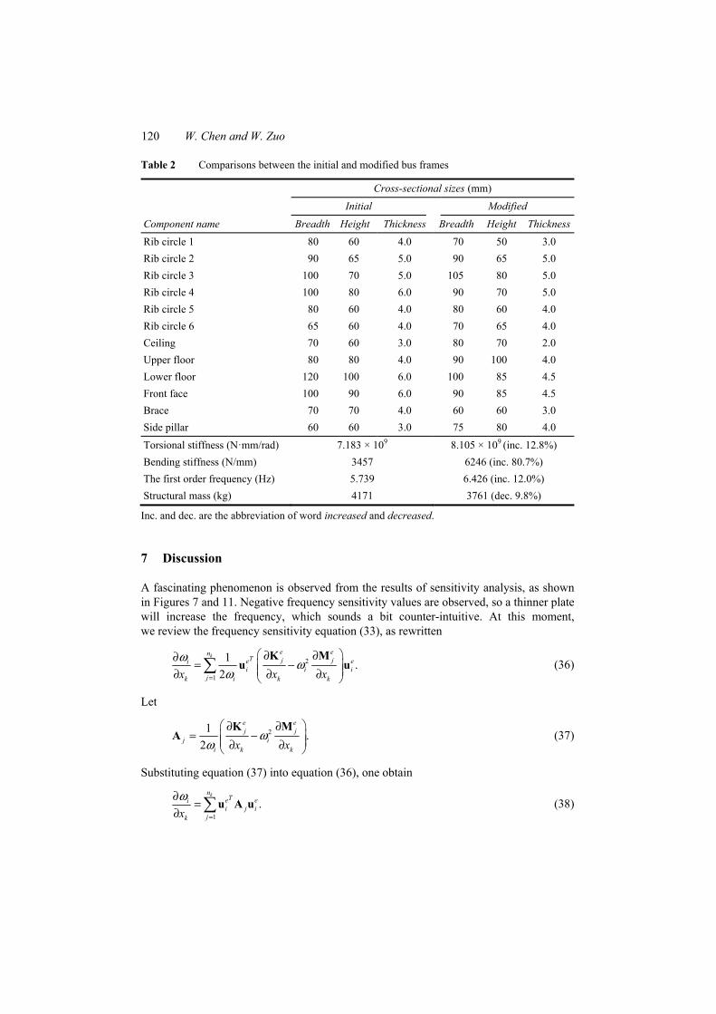
Table 2 Comparisons between the initial and modified bus frames
Component name
Cross-sectional sizes (mm) Initial Modified
Breadth Height Thickness Breadth Height Thickness
Rib circle 1 80 60 4.0 70 50 3.0 Rib circle 2 90 65 5.0 90 65 5.0 Rib circle 3 100 70 5.0 105 80 5.0 Rib circle 4 100 80 6.0 90 70 5.0 Rib circle 5 80 60 4.0 80 60 4.0 Rib circle 6 65 60 4.0 70 65 4.0 Ceiling 70 60 3.0 80 70 2.0 Upper floor 80 80 4.0 90 100 4.0 Lower floor 120 100 6.0 100 85 4.5 Front face 100 90 6.0 90 85 4.5 Brace 70 70 4.0 60 60 3.0 Side pillar 60 60 3.0 75 80 4.0 Torsional stiffness (N·mm/rad) 7.183 × 10⁹ 8.105 × 10⁹
(inc. 12.8%) Bending stiffness (N/mm) 3457 6246 (inc. 80.7%) The first order frequency (Hz) 5.739 6.426 (inc. 12.0%) Structural mass (kg) 4171 3761 (dec. 9.8%)
Inc. and dec. are the abbreviation of word increased and decreased.
7 Discussion
A fascinating phenomenon is observed from the results of sensitivity analysis, as shown in Figures 7 and 11. Negative frequency sensitivity values are observed, so a thinner plate will increase the frequency, which sounds a bit counter-intuitive. At this moment, we review the frequency sensitivity equation (33), as rewritten
2
1
1 .2
k e enT j je ei
i i ijk i k kx x x
ω ωω=
∂ ∂∂= − ∂ ∂ ∂ ∑
K Mu u (36)
Let
21 .2
e ej j
j ii k kx x
ωω
∂ ∂= − ∂ ∂
K MA (37)
Substituting equation (37) into equation (36), one obtain
1
.kn
Te eii j i
jkxω
=
∂=
∂ ∑u A u (38)
Component sensitivity analysis of conceptual vehicle body 121
If any Aj is positive definite, the corresponding quadratic form is satisfied with
0.Te ei j i >u A u (39)
Consequently, the summation form of equation (38) is expressed as
1
0.kn
Te eii j i
jkxω
=
∂= >
∂ ∑u A u (40)
Nevertheless, it is not always guaranteed that each Aj (j = 1, 2, 3, …, nc) is positive definite. In other words, positive definite Aj (j = 1, 2, 3, …, nc) is only the sufficient condition to obtain positive frequency sensitivity. So the frequency sensitivity values can be positive or negative, verified by Figures 7 and 11.
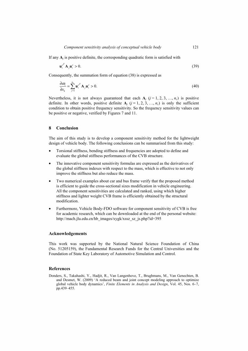
8 Conclusion
The aim of this study is to develop a component sensitivity method for the lightweight design of vehicle body. The following conclusions can be summarised from this study:
• Torsional stiffness, bending stiffness and frequencies are adopted to define and evaluate the global stiffness performances of the CVB structure.
• The innovative component sensitivity formulas are expressed as the derivatives of the global stiffness indexes with respect to the mass, which is effective to not only improve the stiffness but also reduce the mass.
• Two numerical examples about car and bus frame verify that the proposed method is efficient to guide the cross-sectional sizes modification in vehicle engineering. All the component sensitivities are calculated and ranked, using which higher stiffness and lighter weight CVB frame is efficiently obtained by the structural modification.
• Furthermore, Vehicle Body-FDO software for component sensitivity of CVB is free for academic research, which can be downloaded at the end of the personal website: http://mach.jlu.edu.cn/hb_images/xygk/xssz_sz_js.php?id=395
Acknowledgements
This work was supported by the National Natural Science Foundation of China (No. 51205159), the Fundamental Research Funds for the Central Universities and the Foundation of State Key Laboratory of Automotive Simulation and Control.
References Donders, S., Takahashi, Y., Hadjit, R., Van Langenhove, T., Brughmans, M., Van Genechten, B.
and Desmet, W. (2009) ‘A reduced beam and joint concept modeling approach to optimize global vehicle body dynamics’, Finite Elements in Analysis and Design, Vol. 45, Nos. 6–7, pp.439–455.

122 W. Chen and W. Zuo
Gauchia, A., Diaz, V., Boada, M. and Boada, B. (2010) ‘Torsional stiffness and weight optimization of a real bus structure’, International Journal of Automotive Technology, Vol. 11, No. 1, pp.41–47.
Gombor, B. (2005) ‘Dynamic analysis of a bus body frame: determination of the loads and stresses’, Vehicle System Dynamics, Vol. 43, No. 11, pp.807–822.
Hou, W., Zhang, H., Zhang, W. and Hu, P. (2011) ‘Rapid structural property evaluation system for car body advanced design’, International Journal of Vehicle Design, Vol. 57, Nos. 2–3, pp.242–253.
Mundo, D., Donders, S., Stigliano, G. and Van Der Auweraer, H. (2011) ‘Concept design of vehicle bodies using reduced models of beams, joints and panels’, International Journal of Vehicle Design, Vol. 57, No. 1, pp.71–83.
Sergeyev, O. and Mróz, Z. (2000) ‘Sensitivity analysis and optimal design of 3D frame structures for stress and frequency constraints’, Computers and Structures, Vol. 75, No. 2, pp.167–185.
Torstenfelt, B. and Klarbring, A. (2006) ‘Structural optimization of modular product families with application to car space frame structures’, Structural and Multidisciplinary Optimization, Vol. 32, No. 2, pp.133–140.
Torstenfelt, B. and Klarbring, A. (2007) ‘Conceptual optimal design of modular car product families using simultaneous size, shape and topology optimization’, Finite Elements in Analysis and Design, Vol. 43, No. 14, pp.1050–1061.
Xia, L., Zhu, J. and Zhang, W. (2012a) ‘Sensitivity analysis with the modified Heaviside function for the optimal layout design of multi-component systems’, Computer Methods in Applied Mechanics and Engineering, Vols. 241–244, pp.142–154.
Xia, L., Zhu, J. and Zhang, W. (2012b) ‘A superelement formulation for the efficient layout design of complex multi-component system’, Structural and Multidisciplinary Optimization, Vol. 45, No. 5, pp.643–655.
Zhang, S. and Prater Jr., G. (2011) ‘Gauge sensitivity indices and application for assessing vehicle body structural stiffness’, International Journal of Vehicle Design, Vol. 57, No. 1, pp.1–16.
Zhou, M., Pagaldipti, N., Thomas, H.L. and Shyy, Y.K. (2000) ‘An integrated approach for topology, sizing and shape optimization’, Structural and Multidisciplinary Optimization, Vol. 26, No. 5, pp.308–317.
Zhu, J., Zhang, W. and Beckers, P. (2009) ‘Integrated layout design of multi-component system’, International Journal for Numerical Methods in Engineering, Vol. 78, No. 6, pp.631–651.
Zuo, W. (2013) ‘An object-oriented graphics interface design and optimization software for cross-sectional shape of automobile body’, Advances in Engineering Software, Vol. 64, pp.1–10.
Zuo, W., Li, W., Xu, T., Xuan, S. and Na, J. (2012) ‘A complete development process of finite element software for body-in-white structure with semi-rigid beam in .NET framework’, Advances in Engineering Software, Vol. 45, No. 1, pp.261–271.
Component sensitivity analysis of conceptual vehicle body 123
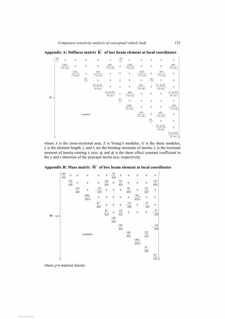
Appendix A: Stiffness matrix eK of box beam element at local coordinates
3 2 3 2
3 2 3 2
2
0 0 0 0 0 0 0 0 0 0
12 6 12 60 0 0 0 0 0 0(1 ) (1 ) (1 ) (1 )
12 6 12 60 0 0 0 0 0
(1 ) (1 ) (1 ) (1 )
0 0 0 0 0 0 0
(4 ) 6 (2 )0 0 0 0
(1 ) (1(1 )
z z z z
y y y y
y y y y
z z z z
x x
z y y z y
z zz
e
EA EAl l
EI EI EI EIl l l l
EI EI EI EIl l l l
GI GIl l
EI EI EIl ll
φ φ φ φ
φ φ φ φ
φ φφ φφ
−
−+ + + +
− − −+ + + +
−
+ −+ ++
=K2
3 2
3 2
0)
(4 ) (2 )60 0 0 0
(1 ) (1 )(1 )
0 0 0 0 0
12 60 0 0(1 ) (1 )
12 6symmetry 0 0
(1 ) (1 )
0 0
(4 )0
(1 )(4 )
(1 )
y z y zz
y yy
z z
y y
y y
z z
x
z y
z
y z
y
EI EIEIl ll
EAl
EI EIl l
EI EIl l
GIl
EIl
EIl
φ φφ φφ
φ φ
φ φ
φφ
φφ
+ − − + ++ − + + + +
+ + +
+
where A is the cross-sectional area, E is Young’s modulus, G is the shear modulus, L is the element length; Iy and Iz are the bending moments of inertia, Ix is the torsional moment of inertia rotating x axis; φy and φz is the shear effect constant coefficient in the y and z direction of the principal inertia axis, respectively.
Appendix B: Mass matrix eM of box beam element at local coordinates
2 2
2 2
140 700 0 0 0 0 0 0 0 0 0420 420
156 22 54 130 0 0 0 0 0 0420 420 420 420
156 22 54 130 0 0 0 0 0420 420 420 420
140 700 0 0 0 0 0 0
420 4204 13 30 0 0 0 0420 420 420
4 13 30 0 0 0420 420 420
140420
156 22420 420
156 22symmetry420 420
140
x x
e
l l
l l
I IA A
l l l
l l l
A
l
l
ρ
−
− −
−=
−
M
2
2
4204420
4420
xIA
l
l
where ρ is material density.
View publication statsView publication stats