Embed Size (px)
Citation preview
L O C K H E E D
A SERVICE PUBLICATION OFLOCKHEED MARTINAERONAUTICAL SYSTEMS
EditorCharles I. Gale
Art DirectionAnne G. Anderson
Vol 22, No.1 January-March 1995
CONTENTS
2
3
7
10
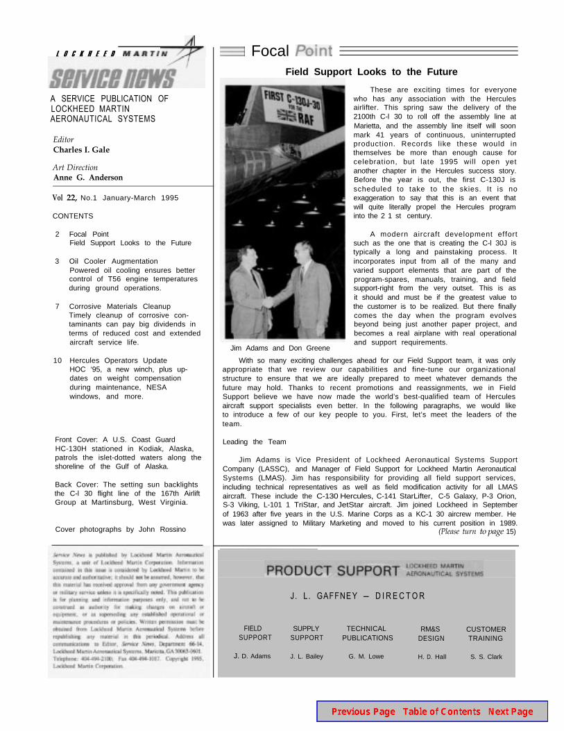
Focal PointField Support Looks to the Future
Oil Cooler AugmentationPowered oil cooling ensures bettercontrol of T56 engine temperaturesduring ground operations.
Corrosive Materials CleanupTimely cleanup of corrosive con-taminants can pay big dividends interms of reduced cost and extendedaircraft service life.
Hercules Operators UpdateHOC ‘95, a new winch, plus up-dates on weight compensationduring maintenance, NESAwindows, and more.
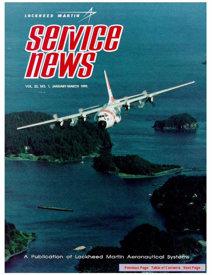
Front Cover: A U.S. Coast GuardHC-130H stationed in Kodiak, Alaska,patrols the islet-dotted waters along theshoreline of the Gulf of Alaska.
Back Cover: The setting sun backlightsthe C-l 30 flight line of the 167th AirliftGroup at Martinsburg, West Virginia.
Cover photographs by John Rossino
Focal Field Support Looks to the Future
These are exciting times for everyonewho has any association with the Herculesairlifter. This spring saw the delivery of the2100th C-l 30 to roll off the assembly line atMarietta, and the assembly line itself will soonmark 41 years of continuous, uninterruptedproduction. Records like these would inthemselves be more than enough cause forcelebration, but late 1995 will open yetanother chapter in the Hercules success story.Before the year is out, the first C-130J isscheduled to take to the skies. It is noexaggeration to say that this is an event thatwill quite literally propel the Hercules programinto the 2 1 st century.
Jim Adams and Don Greene
A modern aircraft development effortsuch as the one that is creating the C-l 30J istypically a long and painstaking process. Itincorporates input from all of the many andvaried support elements that are part of theprogram-spares, manuals, training, and fieldsupport-right from the very outset. This is asit should and must be if the greatest value tothe customer is to be realized. But there finallycomes the day when the program evolvesbeyond being just another paper project, andbecomes a real airplane with real operationaland support requirements.
With so many exciting challenges ahead for our Field Support team, it was onlyappropriate that we review our capabilities and fine-tune our organizationalstructure to ensure that we are ideally prepared to meet whatever demands thefuture may hold. Thanks to recent promotions and reassignments, we in FieldSupport believe we have now made the world’s best-qualified team of Herculesaircraft support specialists even better. In the following paragraphs, we would liketo introduce a few of our key people to you. First, let’s meet the leaders of theteam.
Leading the Team
Jim Adams is Vice President of Lockheed Aeronautical Systems SupportCompany (LASSC), and Manager of Field Support for Lockheed Martin AeronauticalSystems (LMAS). Jim has responsibility for providing all field support services,including technical representatives as well as field modification activity for all LMASaircraft. These include the C-130 Hercules, C-141 StarLifter, C-5 Galaxy, P-3 Orion,S-3 Viking, L-101 1 TriStar, and JetStar aircraft. Jim joined Lockheed in Septemberof 1963 after five years in the U.S. Marine Corps as a KC-1 30 aircrew member. Hewas later assigned to Military Marketing and moved to his current position in 1989.
(Please turn to page 15)
J . L . GAFFNE Y - D I R E C T O R
FIELD SUPPLYSUPPORT SUPPORT
J. D. Adams J. L. Bailey
TECHNICALPUBLICATIONS
G. M. Lowe
RM&SDESIGN
H. D. Hall
CUSTOMERTRAINING
S. S. Clark
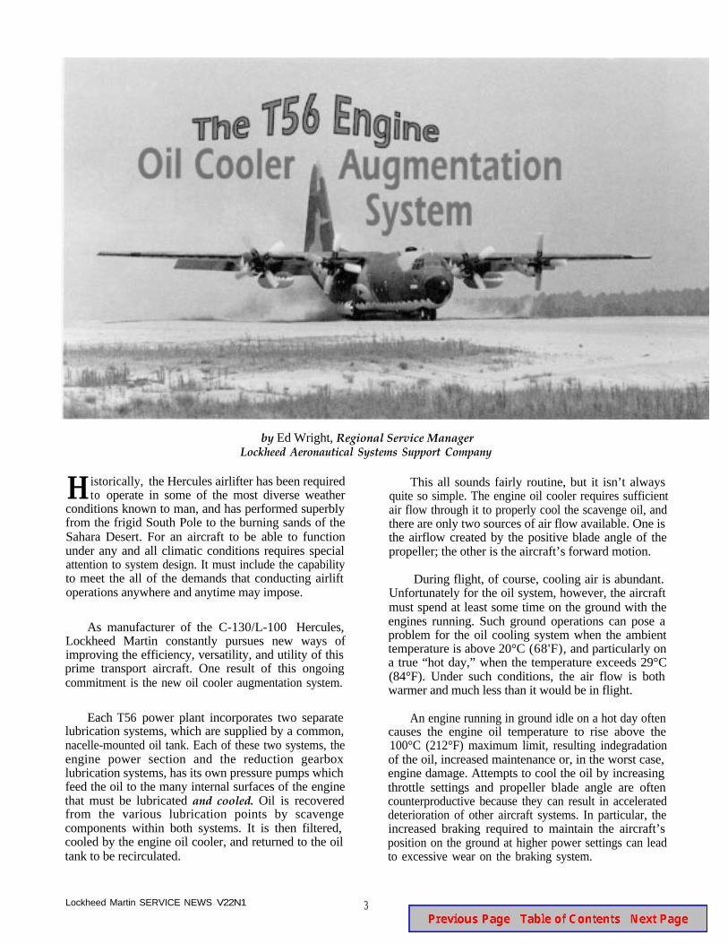
by Ed Wright, Regional Service ManagerLockheed Aeronautical Systems Support Company
H istorically, the Hercules airlifter has been requiredto operate in some of the most diverse weather
conditions known to man, and has performed superblyfrom the frigid South Pole to the burning sands of theSahara Desert. For an aircraft to be able to functionunder any and all climatic conditions requires specialattention to system design. It must include the capabilityto meet the all of the demands that conducting airliftoperations anywhere and anytime may impose.
As manufacturer of the C-130/L-100 Hercules,Lockheed Martin constantly pursues new ways ofimproving the efficiency, versatility, and utility of thisprime transport aircraft. One result of this ongoingcommitment is the new oil cooler augmentation system.
Each T56 power plant incorporates two separatelubrication systems, which are supplied by a common,nacelle-mounted oil tank. Each of these two systems, theengine power section and the reduction gearboxlubrication systems, has its own pressure pumps whichfeed the oil to the many internal surfaces of the enginethat must be lubricated and cooled. Oil is recoveredfrom the various lubrication points by scavengecomponents within both systems. It is then filtered,cooled by the engine oil cooler, and returned to the oiltank to be recirculated.
This all sounds fairly routine, but it isn’t alwaysquite so simple. The engine oil cooler requires sufficientair flow through it to properly cool the scavenge oil, andthere are only two sources of air flow available. One isthe airflow created by the positive blade angle of thepropeller; the other is the aircraft’s forward motion.
During flight, of course, cooling air is abundant.Unfortunately for the oil system, however, the aircraftmust spend at least some time on the ground with theengines running. Such ground operations can pose aproblem for the oil cooling system when the ambienttemperature is above 20°C (68'F), and particularly ona true “hot day,” when the temperature exceeds 29°C(84°F). Under such conditions, the air flow is bothwarmer and much less than it would be in flight.
An engine running in ground idle on a hot day oftencauses the engine oil temperature to rise above the100°C (212°F) maximum limit, resulting indegradationof the oil, increased maintenance or, in the worst case,engine damage. Attempts to cool the oil by increasingthrottle settings and propeller blade angle are oftencounterproductive because they can result in accelerateddeterioration of other aircraft systems. In particular, theincreased braking required to maintain the aircraft’sposition on the ground at higher power settings can leadto excessive wear on the braking system.
Lockheed Martin SERVICE NEWS V22N1 3
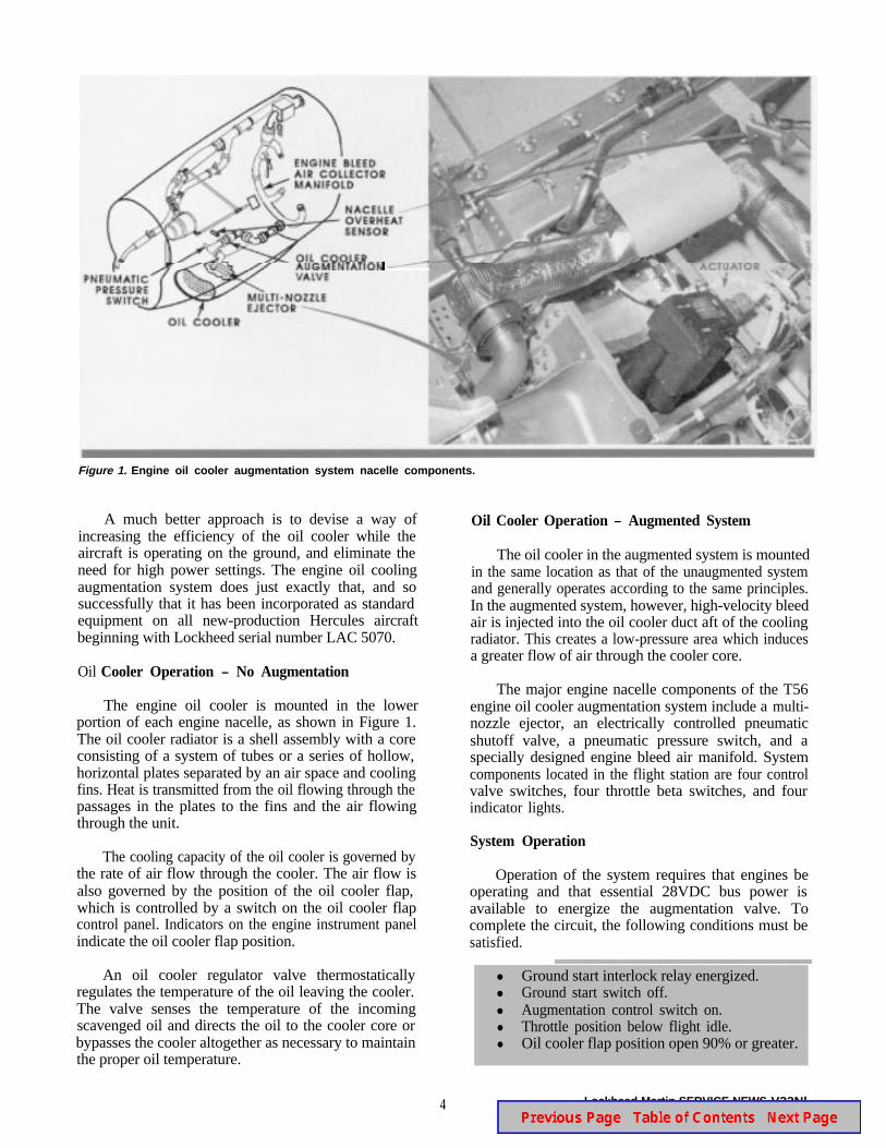
Figure 1. Engine oil cooler augmentation system nacelle components.
A much better approach is to devise a way ofincreasing the efficiency of the oil cooler while theaircraft is operating on the ground, and eliminate theneed for high power settings. The engine oil coolingaugmentation system does just exactly that, and sosuccessfully that it has been incorporated as standardequipment on all new-production Hercules aircraftbeginning with Lockheed serial number LAC 5070.
Oil Cooler Operation - No Augmentation
The engine oil cooler is mounted in the lowerportion of each engine nacelle, as shown in Figure 1.The oil cooler radiator is a shell assembly with a coreconsisting of a system of tubes or a series of hollow,horizontal plates separated by an air space and coolingfins. Heat is transmitted from the oil flowing through thepassages in the plates to the fins and the air flowingthrough the unit.
The cooling capacity of the oil cooler is governed bythe rate of air flow through the cooler. The air flow isalso governed by the position of the oil cooler flap,which is controlled by a switch on the oil cooler flapcontrol panel. Indicators on the engine instrument panelindicate the oil cooler flap position.
An oil cooler regulator valve thermostaticallyregulates the temperature of the oil leaving the cooler.The valve senses the temperature of the incomingscavenged oil and directs the oil to the cooler core orbypasses the cooler altogether as necessary to maintainthe proper oil temperature.
4
Oil Cooler Operation - Augmented System
The oil cooler in the augmented system is mountedin the same location as that of the unaugmented systemand generally operates according to the same principles.In the augmented system, however, high-velocity bleedair is injected into the oil cooler duct aft of the coolingradiator. This creates a low-pressure area which inducesa greater flow of air through the cooler core.
The major engine nacelle components of the T56engine oil cooler augmentation system include a multi-nozzle ejector, an electrically controlled pneumaticshutoff valve, a pneumatic pressure switch, and aspecially designed engine bleed air manifold. Systemcomponents located in the flight station are four controlvalve switches, four throttle beta switches, and fourindicator lights.
System Operation
Operation of the system requires that engines beoperating and that essential 28VDC bus power isavailable to energize the augmentation valve. Tocomplete the circuit, the following conditions must besatisfied.
l Ground start interlock relay energized.l Ground start switch off.l Augmentation control switch on.l Throttle position below flight idle.l Oil cooler flap position open 90% or greater.
Lockheed Martin SERVICE NEWS V22Nl
When the shutoff valve solenoid is energized, itallows pressure from the engine bleed air manifold toopen the shutoff valve. Bleed airflow is directed throughthe valve to the ejector assembly located in the aftsection of the oil cooler duct. The bleed air is injectedinto the duct at a high velocity to create a low-pressurearea behind the oil cooler assembly. This action causesan increase in the volume of air that passes through theoil cooler, thereby allowing more heat to be transferredto the air flow.
Placing the control switch to the off positiondeenergizes the augmentation valve, stopping the flowof bleed air to the ejector assembly. Advancing thethrottle to flight idle or above opens the beta switch, alsodeenergizing the valve. The same thing occurs when theoil cooler flap is closed to the less than 90% openposition.
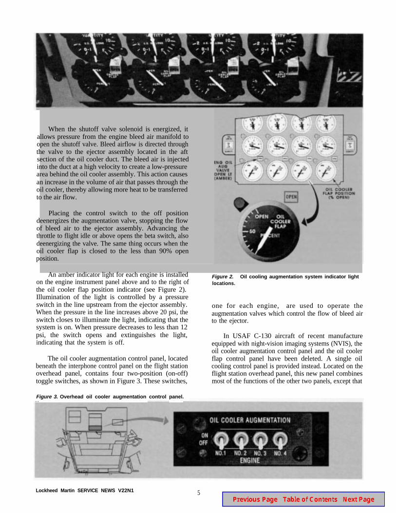
An amber indicator light for each engine is installedon the engine instrument panel above and to the right ofthe oil cooler flap position indicator (see Figure 2).Illumination of the light is controlled by a pressureswitch in the line upstream from the ejector assembly.When the pressure in the line increases above 20 psi, theswitch closes to illuminate the light, indicating that thesystem is on. When pressure decreases to less than 12psi, the switch opens and extinguishes the light,indicating that the system is off.
The oil cooler augmentation control panel, locatedbeneath the interphone control panel on the flight stationoverhead panel, contains four two-position (on-off)toggle switches, as shown in Figure 3. These switches,
Figure 3. Overhead oil cooler augmentation control panel.. .
Figure 2. Oil cooling augmentation system indicator lightlocations.
one for each engine, are used to operate theaugmentation valves which control the flow of bleed airto the ejector.
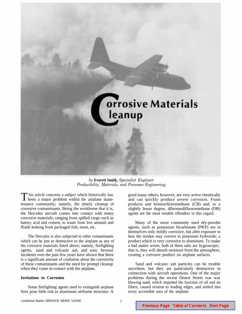
In USAF C-130 aircraft of recent manufactureequipped with night-vision imaging systems (NVIS), theoil cooler augmentation control panel and the oil coolerflap control panel have been deleted. A single oilcooling control panel is provided instead. Located on theflight station overhead panel, this new panel combinesmost of the functions of the other two panels, except that
Lockheed Martin SERVICE NEWS V22N1 5
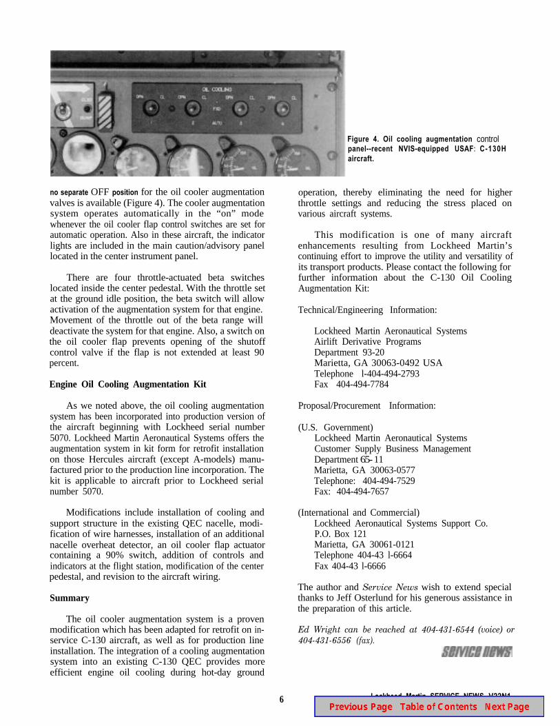
Figure 4. Oil cooling augmentationpanel--recent NVIS-equipped USAFaircraft.
control: C-130H
no separate OFF position for the oil cooler augmentationvalves is available (Figure 4). The cooler augmentationsystem operates automatically in the “on” modewhenever the oil cooler flap control switches are set forautomatic operation. Also in these aircraft, the indicatorlights are included in the main caution/advisory panellocated in the center instrument panel.
There are four throttle-actuated beta switcheslocated inside the center pedestal. With the throttle setat the ground idle position, the beta switch will allowactivation of the augmentation system for that engine.Movement of the throttle out of the beta range willdeactivate the system for that engine. Also, a switch onthe oil cooler flap prevents opening of the shutoffcontrol valve if the flap is not extended at least 90percent.
Engine Oil Cooling Augmentation Kit
As we noted above, the oil cooling augmentationsystem has been incorporated into production version ofthe aircraft beginning with Lockheed serial number5070. Lockheed Martin Aeronautical Systems offers theaugmentation system in kit form for retrofit installationon those Hercules aircraft (except A-models) manu-factured prior to the production line incorporation. Thekit is applicable to aircraft prior to Lockheed serialnumber 5070.
Modifications include installation of cooling andsupport structure in the existing QEC nacelle, modi-fication of wire harnesses, installation of an additionalnacelle overheat detector, an oil cooler flap actuatorcontaining a 90% switch, addition of controls andindicators at the flight station, modification of the centerpedestal, and revision to the aircraft wiring.
Summary
The oil cooler augmentation system is a provenmodification which has been adapted for retrofit on in-service C-130 aircraft, as well as for production lineinstallation. The integration of a cooling augmentationsystem into an existing C-130 QEC provides moreefficient engine oil cooling during hot-day ground
6
operation, thereby eliminating the need for higherthrottle settings and reducing the stress placed onvarious aircraft systems.
This modification is one of many aircraftenhancements resulting from Lockheed Martin’scontinuing effort to improve the utility and versatility ofits transport products. Please contact the following forfurther information about the C-130 Oil CoolingAugmentation Kit:
Technical/Engineering Information:
Lockheed Martin Aeronautical SystemsAirlift Derivative ProgramsDepartment 93-20Marietta, GA 30063-0492 USATelephone l-404-494-2793Fax 404-494-7784
Proposal/Procurement Information:
(U.S. Government)Lockheed Martin Aeronautical SystemsCustomer Supply Business ManagementDepartment 65- 11Marietta, GA 30063-0577Telephone: 404-494-7529Fax: 404-494-7657
(International and Commercial)Lockheed Aeronautical Systems Support Co.P.O. Box 121Marietta, GA 30061-0121Telephone 404-43 l-6664Fax 404-43 l-6666
The author and Service News wish to extend specialthanks to Jeff Osterlund for his generous assistance inthe preparation of this article.
Ed Wright can be reached at 404-431-6544 (voice) or404-431-6556 (fax).
Lockheed Martin SERVICE NEWS V22N1
by Everett Smith, Specialist EngineerProducibility, Materials, and Processes Engineering
T his article concerns a subject which historically hasbeen a major problem within the airplane main-
tenance community; namely, the timely cleanup ofcorrosive contaminants. Being the workhorse that it is,the Hercules aircraft comes into contact with manycorrosive materials, ranging from spilled cargo such asbattery acid and cement, to waste from live animals andfluids leaking from packaged fish, meat, etc.
The Hercules is also subjected to other contaminantswhich can be just as destructive to the airplane as any ofthe corrosive materials listed above; namely, firefightingagents, sand and volcanic ash, and soot. Severalincidents over the past few years have shown that thereis a significant amount of confusion about the corrosivityof these contaminants and the need for prompt cleanupwhen they come in contact with the airplane.
Invitations to Corrosion
Some firefighting agents used to extinguish airplanefires pose little risk to aluminum airframe structure. A
Lockheed Martin SERVICE NEWS V22Nl
good many others, however, are very active chemicallyand can quickly produce severe corrosion. Foamproducts and bromochloromethane (CB) and, to aslightly lesser degree, dibromodifluoromethane (DB)agents are the most notable offenders in this regard.
Many of the more commonly used dry-powderagents, such as potassium bicarbonate (PKP) are inthemselves only mildly corrosive, but after exposure toheat the residue may convert to potassium hydroxide, aproduct which is very corrosive to aluminum. To makea bad matter worse, both of these salts are hygroscopic;that is, they will absorb moisture from the atmosphere,creating a corrosive poultice on airplane surfaces.
Sand and volcanic ash particles can be troubleanywhere, but they are particularly destructive inconnection with aircraft operations. One of the majorproblems during the recent Desert Storm war wasblowing sand, which impeded the function of oil and airfilters, caused erosion to leading edges, and settled intoevery accessible area of the airplane.
7

The abrasive and obstructive nature of sand particlesis only part of the problem, however. Even though thedryness of the climate might appear to offer anacceptable environment for aluminum structure, mostdeserts are the sites of ancient sea beds and the sandoften contains a significant amount of salt.
Volcanic ash provides an even more exotic mix ofabrasive and corrosive elements. In recent years, therehas been a spate of volcanic eruptions which spewed ashinto the air for great heights.Samples of volcanic ashtaken from the Mt. St. Helens and Mt. Pinatuboeruptions were analyzed and found to contain significantquantities of corrosive materials such as sulfuric acidand chloride salts.
Last, but not least, there is the problem of soot. Thesoot generated by an airplane fire is carbon that iscontaminated by a variety of combustion products,depending on what has been burned. Soot is bothcorrosive and hygroscopic, no matter whether the sootis generated by a fire or from normal engine operation.
A problem with all of these corrosive agents is thatdetermining just when the airplane may be subjected tothem normally cannot be predicted. What is important,however, is that the cleanup begin as soon as possibleafter contact, and knowing the correct cleanupprocedures to prevent further damage. With a fewvariations, cleanup of firefighting agents, sand, andvolcanic ash is accomplished in the same manner.
Firefighting Agents
On the Hercules, CB or DB extinguishing agents areused in the engine and APU areas. CB is also used insome fuselage hand-held fire extinguishers. Both ofthese materials are in themselves corrosive, and theircorrosive action is increased if moisture is present.When enough heat (900°F) is added to the mix they willturn acidic, making them even more likely to causecorrosion damage. In addition to the corrosive effect onmetal surfaces, both products will also damage paint,sealant, and adhesives within the contaminated area.
The critical importance of a prompt cleanup after afire cannot be overemphasized. Besides water, firetrucks generally use aqueous film-forming foam (AFFF)or a dry powder (PKP) extinguishing agents. In a recentincident, protein foam, Aero-Foam 3%, was used toextinguish an engine fire. An unfortunate fact aboutprotein foam from the standpoint of metallic surfaces isthat it is usually made from animal blood, whichcontains salt and is extremely corrosive. In this case, thepost-fire cleanup was not done for over a week, and asa consequence the engine and surrounding structurewere severely corroded.
To clean up CB and DB, follow this procedure:
l Ventilate the area
l Remove the residue with dry rags or sponges
From firefighting agents to animal waste: prompt cleanup is the kev to preventing corrosive materials damage.
8 Lockheed Martin SERVICE NEWS V22Nl
l Clean with Stoddard solvent, PD-680, type II,or equivalent
l Apply a 10% solution of sodium bicarbonate or athree parts alkaline cleaning compound to 1 partwater (3:l) to the contaminated areas until thebubbling stops.
l Rinse with clean water and dry the surface.
This procedure can also be used to clean up the proteinfoam by omitting the Stoddard solvent and removing theresidue left by the foam with the 3: 1 solution of alkalinecleaning compound.
Sand, PKP, and Volcanic Ash
For removal of sand, PKP, and volcanic ash, applythe following procedure:
l Gain access to areas of the airplane where thematerial may be trapped.
l Vacuum up all of the residue. A soft bristle brushmay be required to dislodge some debris whilevacuuming.
l Clean with a 3: 1 solution of alkaline cleaningcompound; rinse with clean water and dry thesurface.
Note in particular that volcanic ash is usually quiteacidic; therefore, watch for bubbling during the cleaningprocess. If necessary, reapply the cleaning compounduntil the bubbling stops.
Soot
As we have previously noted, soot is carbon, whichby itself is extremely corrosive to aluminum surfaces.However, soot also contains byproducts of the burnedmaterial that produced it, which significantly increasesthe corrosivity.
Of all the materials we have discussed, soot iswithout a doubt the most difficult to clean up. Notsurprisingly, cleaning crews do not always do athorough job removing it, which results in futurecorrosion. In cleaning up soot, there are two options.Option one is to use stiff bristle brushes and a 3: 1solution of alkaline or solvent-type cleaning compound,followed by rinsing with clean water and drying thearea.
Option two involves some initial equipment costs,but the efficiency and ease of cleaning will make up thedifference in labor cost savings. This option is toremove the soot by the abrasive blast method, using aVat-U-Blast or similar type of machine and either
crushed walnut shells or 30/40-grit plastic media. Theuse of walnut shells is not recommended whereentrapment may occur since walnut shells will absorbwater and rot. The decay process releases acids, whichwill result in corrosion of adjacent surfaces.
On the other hand, plastic media are inert and willnot cause corrosion if trapped. When using this methodto remove soot, keep the blast pressure at the lowestlevel which will do the job so as not to damage theairplane. It is best to start at 30 psi, and if it is necessaryto increase the pressure, do it slowly until an optimumpressure not exceeding 50 psi is reached.
Media blasting should only be done on metallicstructure, and should be used with caution. This processmay be used prior to repainting since it will removepaint degraded by the soot. Be especially careful on thinsheets (0.032” and thinner) and clad parts: there is apossibility of oil-canning of thin sheets and rougheningthe surface of the clad.
After the blasting process is complete, vacuum upany stray media and clean, prime, and paint the affectedsurface to match the surrounding structure. Theinorganic finish (chemical conversion coating, sulfuricacid anodize, etc.) may be removed by aggressiveblasting. If this occurs, apply a chemical conversioncoating prior to applying the primer and paint topcoat.
Some exterior areas of the airplane that may becontaminated by impingement of engine soot can beprotected with the use of a soil barrier. After the wash,and before the airplane dries, apply a thin coat of Cee-Bee A-6 or Eldorado PC 1020 (or equivalent) soilbarrier. If the area was just repainted, wait until thepaint has cured and spray the surface with water beforeapplication of the soil barrier.
The typical Hercules airlifter is subjected to manycorrosive influences in the course of completing itseveryday tasks. Preventing potential corrosion fromturning into real corrosion is one of the most importantand worthwhile maintenance activities that any aircraftoperator can perform.
Any time spent in protecting your aircraft from thedestructive effects of strong chemicals, sand, ash, andsoot will pay big dividends in terms of cost savings andsafety. Looked at another way, removing corrosivematerials in a timely manner helps extend the workinglife of the Hercules aircraft. Conscientious applicationof the techniques described in this article will assist you,the operator, in your efforts to fly a well-maintainedairplane in the most economical way.
Everett Smith has recently retired. Questions concerningthis article may be directed to Scott Jones at 404-494-3849 (voice) or 404-494-9610 (fax).
Lockheed Martin SERVICE NEWS V22Nl 9
1995 HERCULES OPERATORS CONFERENCE (HOC 1995)
During the week of 16 October, 1995, representatives of Hercules owners andoperators, Hercules Service Centers, major Hercules vendors, and Lockheed Martin willassemble at the Atlanta Marriott Northwest to discuss matters of common interestrelative to the operation of world’s most famous airlifter. This important conference wasestablished in 1982 to provide a forum wherein Hercules owners and operators couldexchange ideas with each other and Lockheed personnel. Attendance has grown fromjust fifteen in 1982 to more than 250 in 1994. The attendees at HOC 1994 represented82 owners and operators from every corner of the globe. Lockheed expects anotherproductive and record-setting meeting during HOC 95. Don’t miss it!
AN IMPROVED CARGO WINCH
Problems with the procurement of the PN 41750-3041 BG cargo winch have made itnecessary to establish a new source for this important piece of accessory equipment.The PN 9440-I 1 cargo winch, manufactured by the Teleflex Corporation, meets all therequirements for use in Hercules aircraft and now has been approved as an alternate.
A number of important improvements have been included in the new winch. Amongthese are increased reliability, a level-cable mechanism, and remote control capability.Other features offered by the new unit are the following:
l Single-cable pull limit of 6500 pounds, and up to 13,OOO pounds capacity (with somerestrictions) when utilizing a snatch block.
l A control pendant equipped with a three-position toggle switch attached to the endof a 105-foot cable.
l A powerful 115/200 VAC, 400 Hz, 3-phase motor.
l Essentially one-man operation.
l A level-wind mechanism capable of directing the cable onto the drum evenly.
l A load-limit device.
10 Lockheed Martin SERVICE NEWS V22Nl
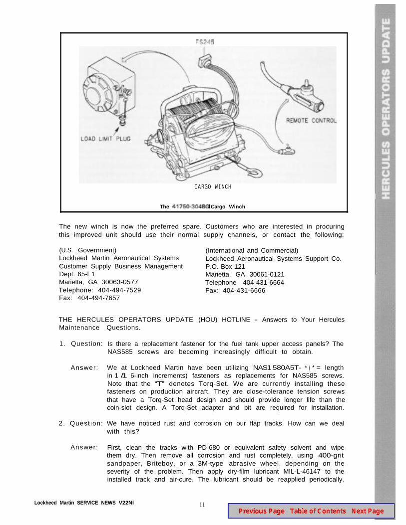
CARGO WINCH
The Cargo Winch
The new winch is now the preferred spare. Customers who are interested in procuringthis improved unit should use their normal supply channels, or contact the following:
(U.S. Government)Lockheed Martin Aeronautical SystemsCustomer Supply Business ManagementDept. 65-l 1Marietta, GA 30063-0577Telephone: 404-494-7529Fax: 404-494-7657
(International and Commercial)Lockheed Aeronautical Systems Support Co.P.O. Box 121Marietta, GA 30061-0121Telephone 404-431-6664Fax: 404-431-6666
THE HERCULES OPERATORS UPDATE (HOU) HOTLINE - Answers to Your HerculesMaintenance Questions.
1. Question:
Answer:
2. Quest ion:
Answer:
Is there a replacement fastener for the fuel tank upper access panels? TheNAS585 screws are becoming increasingly difficult to obtain.
We at Lockheed Martin have been utilizing NAS1 580A5T- * ( * = lengthin 1 /1 6-inch increments) fasteners as replacements for NAS585 screws.Note that the “T” denotes Torq-Set. We are currently installing thesefasteners on production aircraft. They are close-tolerance tension screwsthat have a Torq-Set head design and should provide longer life than thecoin-slot design. A Torq-Set adapter and bit are required for installation.
We have noticed rust and corrosion on our flap tracks. How can we dealwith this?
First, clean the tracks with PD-680 or equivalent safety solvent and wipethem dry. Then remove all corrosion and rust completely, using 400-gritsandpaper, Briteboy, or a 3M-type abrasive wheel, depending on theseverity of the problem. Then apply dry-film lubricant MIL-L-46147 to theinstalled track and air-cure. The lubricant should be reapplied periodically.
Lockheed Martin SERVICE NEWS V22Nl 11
3. Question: How can we compensate for the removed weight when engines orpropellers are removed from one side of the aircraft only?
Answer: Because of main strut friction, removing a propeller or even bothpropellers on one side may or may not cause the airplane to tilt slightly.However, it should be anticipated that removing a QEC will cause theairplane to tilt. Thus all personnel must be kept clear, and work stands orother equipment should be moved from under the opposite wing beforeremoving a propeller or QEC.
The tilt angle which results depends on the weight of the airplane, theamount of fuel on board, and the weight and c.g. of any cargo on board.Thanks to the main strut load-stroke characteristics, a light airplane willtilt more that a heavy airplane with the same fuel load. When the airplanedoes tilt in response to the removal of engines and/or propellers, the fuelwithin each internal wing tank will shift in the direction of the lower wingtip, thereby further increasing the unbalance and thus the tilt. If cargo hasbeen loaded with an off-center c.g. (not on BL 0), this unbalance will addto the unbalance that resulted from the removal of a propeller or QEC onthe opposite side.
When lateral unbalance is created by the removal of one or both propellersand/or engines from one side, a possible solution to the problem is totransfer fuel to the lighter side of the aircraft. Several factors must beconsidered in determining if it is necessary to transfer fuel to restorelateral balance.
I. If the airplane is parked outside, what winds are anticipated? Lateralunbalance reduces the wind speed the aircraft can withstand withouttipping sideways. If a storm that may have wind speeds of 48 knotsand above is approaching, fuel should be transferred to restore lateralbalance, or wing mooring cables should be installed, making sure thatthere is no slack in the cable attached to the light wing.
2. The ground handling and servicing manual defines the reduction inallowable weight for jacking if the airplane is not laterally balanced.
3. Tilting of the airplane will not cause excessive stresses on theairframe. However, it is not recommended that a condition of largeunbalance be allowed to exist for periods of several days.
The following moments may be used to determine the amount of fuelwhich needs to be transferred to restore lateral balance if this is judged tobe necessary. Bear in mind that the fuel unbalance limits given in the flightmanual-which specifies a limit of 1000 pounds difference betweensymmetrical tanks-apply while the airplane is being flown or taxied, butnot during maintenance activities, including towing. Be sure to keeppersonnel, workstands, etc. away from the wings when transferring fuel,and remember to transfer the fuel back when the engines and/or propellersare reinstalled.
ITEM MOMENT(inch-pounds)
No. 1 or No. 4 propeller 426 ,400No. 2 or No. 3 propeller 208 ,940No. 1 or No. 4 QEC (including propeller) 1,620,OOONo. 2 or No. 3 QEC (including propeller) 793 ,800
12 Lockheed Martin SERVICE NEWS V22Nl
Fuel asymmetry for each 1000 difference:
Between tanks No. 1 and No. 4 534 ,000”Between tanks No. 2 and No. 3 284 ,000”Between auxiliary tank s 120 ,000”Between external tank s 302 ,000
* With wings level
Example: Determine the weight of fuel which must be transferred from tankNo. 3 to tank No. 2 to restore lateral balance after removal of the No. 2 QEC.
Fuel weight difference = 7 9 3 8 0 02 8 4 0 0 0
x 1000 = 2795 pounds
The fuel which must be transferred i s 1/2 of 2795; i.e. about 1400 pounds.
4. Question:
Answer:
5. Question:
Answer:
Can you give us an update on windshields?
Yes. We are pleased to advise that new windshields are available for thepilot, copilot, and center positions. The new design replaces the integralPVB bumper around the perimeter with cast-in-place polysulfide sealant.This design reduces the stresses that act on the glass edge, therebyreducing the number of incidents of cracking. The new PN 337279-l 1and PN 338124-I l/l 2 panel assemblies should be the preferred sparesfor the PN 337279-9 and P N 338124-9/l 0 panels, although all are inter-changeable. The organizations shown in the address blocks in the middleof page 11 can provide price and availability information about the newpanels if desired.
Can we install forward fuselage windows and windshields with theaircraft on jacks?
Windshields and windows should not, repeat , not be installe d whil e theaircraft is supported on jacks. Jacking can strain-load the panels andresult in premature failure. However, the windshields may be installedwhile the aircraft is supported on contoured cradles in accordance withthe applicable maintenance manual. In this situation, the nose jacks
Lockheed Martin SERVICE NEWS V22Nl 13
should be snugged up only (no upload applied), with the weight of thefuselage on the cradles.
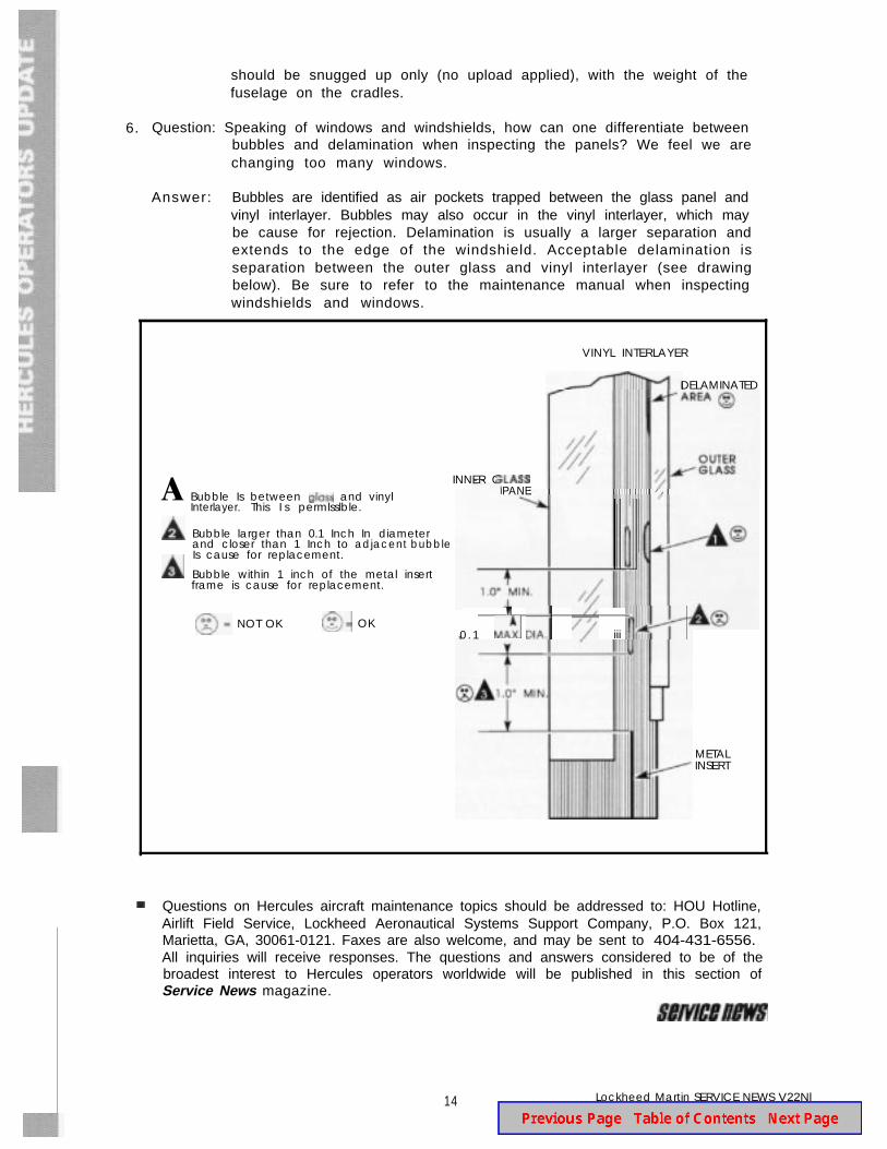
6. Question: Speaking of windows and windshields, how can one differentiate betweenbubbles and delamination when inspecting the panels? We feel we arechanging too many windows.
Answer: Bubbles are identified as air pockets trapped between the glass panel andvinyl interlayer. Bubbles may also occur in the vinyl interlayer, which maybe cause for rejection. Delamination is usually a larger separation andextends to the edge of the windshield. Acceptable delamination isseparation between the outer glass and vinyl interlayer (see drawingbelow). Be sure to refer to the maintenance manual when inspectingwindshields and windows.
A
VINYL INTERLAYER
DELAMINATED
INNER G- - PANEBubble Is between and vinyl
Interlayer. This I s permlsslble.
Bubble larger than 0.1 Inch In diameterand closer than 1 Inch to adjacent bubbleIs cause for replacement.
Bubble within 1 inch of the metal insertframe is cause for replacement.
NOT OK OK0 . 1 iii
METALINSERT
Questions on Hercules aircraft maintenance topics should be addressed to: HOU Hotline,Airlift Field Service, Lockheed Aeronautical Systems Support Company, P.O. Box 121,Marietta, GA, 30061-0121. Faxes are also welcome, and may be sent to 404-431-6556.All inquiries will receive responses. The questions and answers considered to be of thebroadest interest to Hercules operators worldwide will be published in this section ofService News magazine.
14 Lockheed Martin SERVICE NEWS V22Nl
(Continued from page 2)He has held numerous field assignments and supervisory andmanagement positions in Field Support.
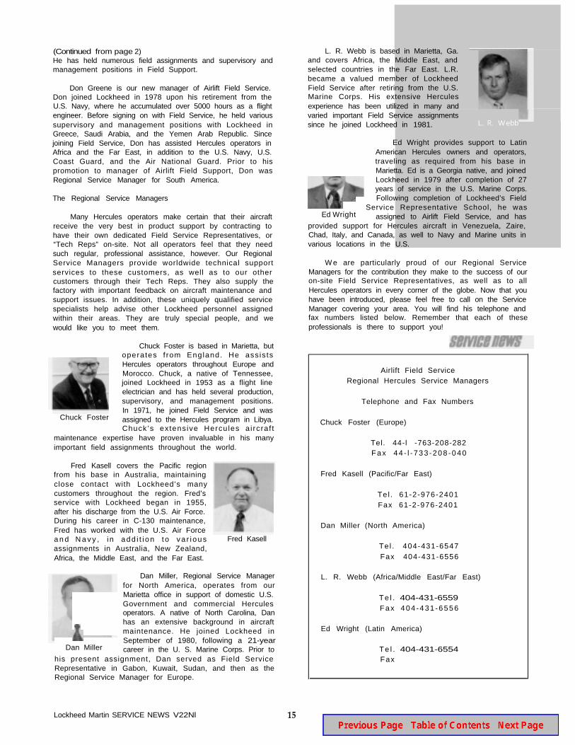
Don Greene is our new manager of Airlift Field Service.Don joined Lockheed in 1978 upon his retirement from theU.S. Navy, where he accumulated over 5000 hours as a flightengineer. Before signing on with Field Service, he held varioussupervisory and management positions with Lockheed inGreece, Saudi Arabia, and the Yemen Arab Republic. Sincejoining Field Service, Don has assisted Hercules operators inAfrica and the Far East, in addition to the U.S. Navy, U.S.Coast Guard, and the Air National Guard. Prior to hispromotion to manager of Airlift Field Support, Don wasRegional Service Manager for South America.
The Regional Service Managers
Many Hercules operators make certain that their aircraftreceive the very best in product support by contracting tohave their own dedicated Field Service Representatives, or“Tech Reps” on-site. Not all operators feel that they needsuch regular, professional assistance, however. Our RegionalService Managers provide worldwide technical supportservices to these customers, as well as to our othercustomers through their Tech Reps. They also supply thefactory with important feedback on aircraft maintenance andsupport issues. In addition, these uniquely qualified servicespecialists help advise other Lockheed personnel assignedwithin their areas. They are truly special people, and wewould like you to meet them.
Chuck Foster is based in Marietta, butoperates f rom England. He ass is tsHercules operators throughout Europe andMorocco. Chuck, a native of Tennessee,joined Lockheed in 1953 as a flight lineelectrician and has held several production,supervisory, and management positions.
Chuck FosterIn 1971, he joined Field Service and wasassigned to the Hercules program in Libya.Chuck’s extens ive Hercules a i rcraf t
maintenance expertise have proven invaluable in his manyimportant field assignments throughout the world.
Fred Kasell covers the Pacific regionfrom his base in Australia, maintainingclose contact with Lockheed’s manycustomers throughout the region. Fred’sservice with Lockheed began in 1955,after his discharge from the U.S. Air Force.During his career in C-130 maintenance,Fred has worked with the U.S. Air Forcea n d N a v y , i n add i t i on t o va r i ousassignments in Australia, New Zealand,Africa, the Middle East, and the Far East.
Fred Kasell
Dan Miller, Regional Service Managerfor North America, operates from our
Marietta office in support of domestic U.S.Government and commercial Herculesoperators. A native of North Carolina, Danhas an extensive background in aircraftmaintenance. He joined Lockheed in
Dan MillerSeptember of 1980, following a 21-yearcareer in the U. S. Marine Corps. Prior to
his present assignment, Dan served as Field ServiceRepresentative in Gabon, Kuwait, Sudan, and then as theRegional Service Manager for Europe.
Lockheed Martin SERVICE NEWS V22Nl 15
L. R. Webb is based in Marietta, Ga.and covers Africa, the Middle East, andselected countries in the Far East. L.R.became a valued member of LockheedField Service after retiring from the U.S.Marine Corps. His extensive Herculesexperience has been utilized in many andvaried important Field Service assignmentssince he joined Lockheed in 1981. L. R. Webb
Ed Wright provides support to Latin
American Hercules owners and operators,
traveling as required from his base in
Marietta. Ed is a Georgia native, and joinedLockheed in 1979 after completion of 27years of service in the U.S. Marine Corps.Following completion of Lockheed’s Field
Service Representative School, he wasEd Wright assigned to Airlift Field Service, and has
provided support for Hercules aircraft in Venezuela, Zaire,Chad, Italy, and Canada, as well to Navy and Marine units invarious locations in the U.S.
W e are particularly proud of our Regional ServiceManagers for the contribution they make to the success of ouron-site Field Service Representatives, as well as to allHercules operators in every corner of the globe. Now that youhave been introduced, please feel free to call on the ServiceManager covering your area. You will find his telephone andfax numbers listed below. Remember that each of theseprofessionals is there to support you!
Airlift Field ServiceRegional Hercules Service Managers
Telephone and Fax Numbers
Chuck Foster (Europe)
Tel. 44-l -763-208-282F a x 4 4 - l - 7 3 3 - 2 0 8 - 0 4 0
Fred Kasell (Pacific/Far East)
Te l . 61-2-976-2401Fax 61-2-976-2401
Dan Miller (North America)
Tel . 404-431-6547Fax 404-431-6556
L. R. Webb (Africa/Middle East/Far East)
T e l . 404-431-6559Fax 404 -431 -6556
Ed Wright (Latin America)
T e l . 404-431-6554Fax