Embed Size (px)
Citation preview
lable at ScienceDirect
International Journal of Lightweight Materials and Manufacture 4 (2021) 110e126
Contents lists avai
International Journal of Lightweight Materials and Manufacture
journal homepage: https: / /www.sciencedirect .com/journal /internat ional- journal-of- l ightweight-mater ia ls-and-manufacture
Review
A review on forming technologies of fibre metal laminates
Zerong Ding a, Hongyan Wang a, Jiaming Luo b, Nan Li a, *
a Dyson School of Design Engineering, Imperial College London, Exhibition Road, London, SW7 2DB, UKb Shougang Research Institute of Technology, Shougang Group, Beijing 100041, China
a r t i c l e i n f o
Article history:Received 24 April 2020Received in revised form22 June 2020Accepted 23 June 2020Available online 4 July 2020
Keywords:Fibre metal laminates (FMLs)Forming technologiesStampingDeformation modes
* Corresponding author.E-mail address: [email protected] (N. Li).Peer review under responsibility of Editorial Boa
Lightweight Materials and Manufacture.
https://doi.org/10.1016/j.ijlmm.2020.06.0062588-8404/© 2020 The Authors. Production and hostlicense (http://creativecommons.org/licenses/by-nc-n
a b s t r a c t
Fibre metal laminates (FMLs), as a class of hybrid material taking advantages of both metals and com-posites, have shown great promise as lightweight structural materials in the transportation industry.Accordingly, manufacturing technologies of FMLs are attracting increasing research interests. This reviewemphasises the developing technologies of forming FML components, with other aspects related to FMLmaterials being briefly introduced. First, we provide an overall review of the historical background andrecent developments of FMLs, their classifications, sheet fabrication processes, and their advantages anddisadvantages. Then, various forming technologies are introduced in detail, with a particular focus onstamp forming, which is considered to be the most promising approach for the high-volume productionof complex-shaped FML components. Furthermore, the deformation modes and defects in forming FMLsare analysed and the challenges encountered in the existing research are thoroughly discussed. Finally,studies on modelling and process simulation of forming FMLs are reviewed and discussed. Based on thecomprehensive appraisal of various aspects, current research progress and challenges related to FMLsand their forming technologies are summarised and an outlook of further developments is discussed.© 2020 The Authors. Production and hosting by Elsevier B.V. on behalf of KeAi Communications Co., Ltd.This is an open access article under the CC BY-NC-ND license (http://creativecommons.org/licenses/by-
nc-nd/4.0/).
1. Introduction
Increasing concern about the climate change [1] has driven theadoption of more rigorous environmental protection policiesglobally, with the aim of reducing carbon footprint [2e4]. Aneffective solution to this task in the transportation industry is toimprove the energy efficiency of vehicles by reducing their struc-tural weight using lightweight materials. Polymer matrix com-posites (PMCs), especially continues fibre-reinforced polymers(FRPs) [5], and modern metallic alloys, such as aluminium alloysand high-strength steels [6,7], have been widely used for aircraftand automotive structures. However, the applications of thesematerials are limited by some of their disadvantages, like poorimpact resistance of FRPs [8,9] and concern about fatigue failure ofmonolithic metal structures [10]. To overcome their respectivedisadvantages, the concept of hybrid material system has beenproposed.
rd of International Journal of
ing by Elsevier B.V. on behalf of Ked/4.0/).
Fibre metal laminates (FMLs) are hybrid material systemsinterlacing metal and FRP sheets, as illustrated in Fig. 1a. They wereinitially developed in the aviation industry to improve fatigueresistance [11]. With other advantages, especially the highstrength-to-weight ratio, FMLs have been considered to be the ideallightweight structural material [8]. The most famous FML is GLARE,which has been successfully applied on the Airbus A380 and pro-vided significant weight reduction with extraordinary fatigue anddamage resistance performance [12]. Recently, increasing researchinterest has been drawn to the development of manufacturingtechnologies for complex-shaped FML components to enable widerindustrial applications. In the automotive industry, a floor assemblyenabled by the development of FML stamp forming technology,demonstrated in Ref. [13], has shown great potentials of FMLs inproviding comparable structural performance with weight reduc-tion by around 25% compared to a full-metal lightweight structure.
The substantial potential of FMLs in industrial applications hasbeen drawing increasing research interest toward various aspectsof FMLs which has been reviewed from time to time. Vlot [11]presented the history of FMLs from its birth to the development andapplication of ARALL and GLARE. Sadighi et al. [14] provided anexperimental review on the impact resistance performance ofFMLs. Morini�ere et al. [15] further reviewed the modelling
Ai Communications Co., Ltd. This is an open access article under the CC BY-NC-ND
Fig. 1. Schematic illustration of (a) various FML structures; (b) example multi-stack FMLs.
Z. Ding et al. / International Journal of Lightweight Materials and Manufacture 4 (2021) 110e126 111
development of impact damage and dynamics of FMLs. Chai andManikandan [16] provided a review which addressed the experi-mental, numerical and analytical work, particularly on the lowvelocity impact response of FMLs. Chandrasekar et al. [17] reviewedthe mechanical properties of FMLs and various failure modes underdifferent loading conditions, as well as their hygrothermal behav-iours. Sinmazçelik [8] provided a review of FMLs in various aspects,including a comprehensive background introduction, bondingprocess, and test methods. Existing reviews as mentioned mainlyfocused on the aspects of the development history of FMLs andtheir performance as structural materials, whereas themanufacturing technologies of FML components has rarely beenreviewed. Sinke [18,19] provided an introduction to the principlesof manufacturing FML components, with a particular focus on lay-up techniques and press-brake bending. Components producedusing these technologies, such as large fuselage panels andstringers respectively, have relatively simple geometries and havealready been commercialised. The latest developments in formingcomplex-shaped FML components, however, have not been thor-oughly reviewed.
This paper aims to provide a comprehensive review of thedeveloping forming technologies of FMLs. An overall introductionto the important aspects of FML materials is briefly presented first,followed by an extensive review of FML forming technologies, witha focus on die forming. In particular, stamping technologies arediscussed in detail on the aspects of processing strategies andforming windows. Then, the deformation modes and challenges inFML forming are discussed, followed by a brief introduction to themodelling and numerical simulation of the FML forming processes.
2. Fibre metal laminates: development, classification,fabrication and characteristics
Although FMLs have been reviewed in various aspects asmentioned earlier, a brief introduction to FMLs is necessary toprovide readers with the most up-to-date information on impor-tant aspects of FMLs, which is the prerequisite information for the
review on forming technologies for FML components described inthe following sections. In this section, the history of the FMLs ispresented first, including more recent developments since the2000s, with a particular focus on the development progress of FMLforming technologies. The classification of FMLs is then discussed,starting with a discussion on the material constituents of FMLs, andfollowed by an introduction to the fabrication process of FMLsheets. The advantages and disadvantages of FMLs are then brieflydiscussed at the end of this section.
2.1. A brief history of the development of FMLs
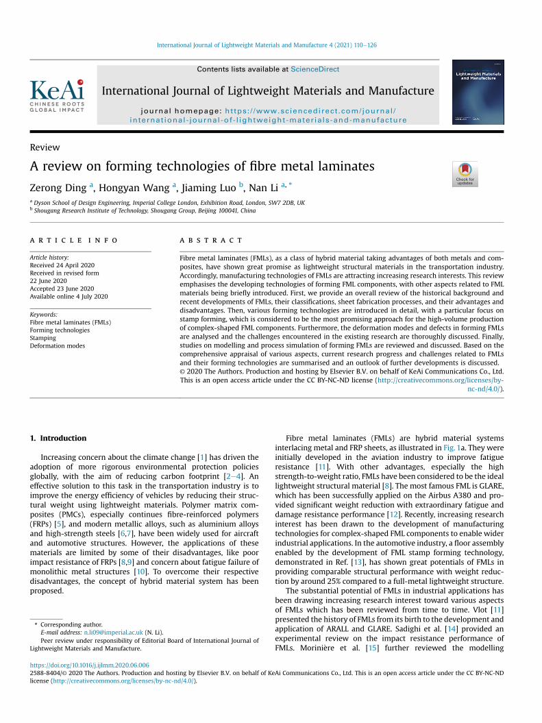
Since their earliest known application in the 1970s [11], FMLshave been attracting increasing industrial interests, and varioustypes of FMLs have been developed and investigated. The history ofthis development is illustrated chronologically in Fig. 2.
In the 1950s, several tragical accidents caused by metal fatiguefailure [10] drove the aviation industry to develop newstructures andadvanced materials for better fatigue resistance. Emerging from thefundamental technologies of metal bonding [20,21] and FRPs [22],Fokker, as a contractor of NASA, embedded fibres into the adhesivebetween titanium layers in the 1970s [11]. Such a material structureshowed an improved fatigue strength, as the embedded fibresresisted the initiating of cracks and further crack growth [23]. Basedon this, Aramid Aluminium Laminate (ARALL), which is an FMLconsisting of aluminium sheets and aramid fibre-reinforced epoxy,was developed at the Delft University of Technology and applied aswing panel materials on the Fokker F-27 in the 1980s [11,23]. Afurther improvement by substituting aramid fibres with glass fibreswas then developed to avoid potential failure when using ARALL asfuselage materials. In the 1990s, Glass Reinforced Aluminium Lami-nate (GLARE)was then developed atDelft and commercialised on theAirbus A380 [11,12]. An insight into this extraordinary venture ofdeveloping ARALL and GLARE can be found in Vlot's book [11].
During the 1990s, various FMLs with different material con-stituents were developed and investigated. Lin et al. [24] replacedthe aramid fibres in ARALL with carbon fibres, and developed
Fig. 2. Development of fibre metal laminates (FMLs).
Z. Ding et al. / International Journal of Lightweight Materials and Manufacture 4 (2021) 110e126112
Carbon Reinforced Aluminium Laminates (CARALL). NASA startedto develop TiGr, which is an FML system consisting of titanium andgraphite fibre-reinforced polymer [25]. Since the 2000s, moremetals, such as steels [26] and magnesium alloys [27], have beenused to construct FML structures. In addition to the exploration ofvarious constituting materials, developing advancedmanufacturing technologies for producing FML components hasbeen a major research topic in the past two decades.
Until 2000, the major manufacturing methods used to produceFML components were bending and lay-up technique. These tech-niques only allowed FML components with simple geometry to bemanufactured. Since the 2000s, research interest has been drawn toproducing complex-shaped FML components via forming, espe-cially die forming technologies. Mosse et al. [28] started investi-gating the formability of aluminium/polypropylene (Al/PP)-basedFMLs. Edwardson et al. [29] investigated the feasibility of laserforming FMLs with various material constituents.
The investigation on forming FMLs drew increasing interest inthe 2010s. Kalyanasundaram et al. [30] investigated the formabilityof Al/PP-based FMLs with double curvature dome stamping. Dauet al. [31] proposed a combined forming process, in which the steelsheet and carbon fibre-reinforced epoxy were formed and joined inone step. Behrens et al. [32] used a similar technique to stamp andjoin steel and carbon fibre-reinforced polyamide 6 (PA6) in onestep. Mennecart et al. [33] combined deep drawing andthermoplastic-resin transfer molding (T-RTM), where steel oraluminium sheets and glass fibres were bonded, embedded andformed with a special thermoplastic matrix in one step. Sherkat-ghanad et al. [34] utilised hydroforming by partially replacing asolid die with pressurised fluid to form FMLs consisting ofaluminium sheets and glass fibre-reinforced prepregs. Chernikovet al. [35] investigated the feasibility of forming GLARE-like FMLswith punch force generated by electro-magnetic pulse. In additionto the various die-forming technologies as mentioned above, otherforming methods were also investigated during these decades.Russig et al. [36] used shot peening forming (SPF), which was anestablished process for fuselage parts, to form GLARE and showed atypical curvature radii of 2500 mm for fuselage panels can beachieved. Al-Obaidi et al. [37] formed Al/PA6-based FMLs withbasalt fibre reinforcement with heat support incremental sheetforming. These forming technologies mentioned will be discussedin detail in section 3.
Among the development of these FML forming technologies,LEIKA was a particularly remarkable project partnering withseveral industrial and academic research institutes [13]. They
developed advanced FML forming technologies [38] which enabledthe production of a multi-material floor panel structure with 25%further weight reduction compared with a full-metal structure [13].This three-year project demonstrated the significant light-weighting opportunities presented by FMLs and their advancedmanufacturing technologies in the automotive industry.
2.2. Classification of FMLs
FMLs can be classified either by their structural arrangements ormaterial constituents. There are variants of FML structural ar-rangements, as illustrated in Fig. 1a, from asymmetric to multi-stacking laminates, based on various performance requirementsand manufacturing considerations [39e41]. Especially for multi-stacking laminates, specialised performance features can be ach-ieved by alternating the stacking arrangement and the fibre ori-entations. For example, GLARE can exhibit different features byalternating the orientations of the unidirectional fibres embeddedin the polymer. As shown in Fig. 1b, GLARE 3 was designed foroptimal fatigue resistance; whilst GLARE 6 was designed forenhancing the shear and off-axis properties [42].
Alternatively, a more recognised classification for FMLs isbased on their material constituents. The constituting materials,in theory, can be selected freely. However, there are many re-strictions to be considered to construct reliable FMLs, to avoidextreme internal stress, galvanic corrosion, voids and volatiles,etc. Availability and cost are also important factors to beconsidered when selecting the material constituents of FMLs[43]. FML material constituents in the literature are summarisedand presented in Fig. 3. Based on the material constituents, FMLscan be primarily classified by the base metals and then thecomposites, which each consists of matrix and fibre reinforce-ment. Compared with the classification in previous reviews[8,16,17], this figure includes the recent exploration of steel-based FMLs and thermoplastic-based FRPs.
Aluminium-based FMLs are the most commonly investigatedand developed FML as aluminium is the most widespread struc-tural material in the modern aviation industry. Several aluminium-based FMLs, such as ARALL and GLARE, have been commercialisedas fuselage and wing panel materials, as mentioned in the previoussections [11]. Titanium-based FMLs have also been investigated byleading aerospace research institutes such as NASA [25,53].Recently, studies have commenced on steel-based andmagnesium-based FMLs as potential lightweighting solutions for the automo-tive industry [13].
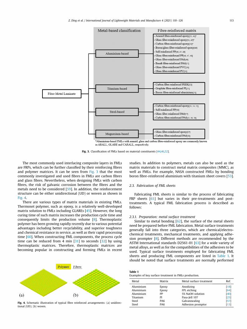
Fig. 3. Classification of FMLs based on material constituents [44,46,52].
Z. Ding et al. / International Journal of Lightweight Materials and Manufacture 4 (2021) 110e126 113
The most commonly used interlacing composite layers in FMLsare FRPs, which can be further classified by their reinforcing fibresand polymer matrices. It can be seen from Fig. 3 that the mostcommonly investigated and used fibres in FMLs are carbon fibresand glass fibres. Nevertheless, when designing FMLs with carbonfibres, the risk of galvanic corrosion between the fibres and themetals need to be considered [59]. In addition, the reinforcementstructure can be either unidirectional (UD) or woven as shown inFig. 4.
There are various types of matrix materials in existing FMLs.Thermoset polymer, such as epoxy, is a relatively well-developedmatrix solution to FMLs including GLAREs [45]. However, the longcuring time of such matrix increases the production cycle time andconsequently limits the production volume [8]. Thermoplasticpolymer has been growing rapidly recently due to various potentialadvantages including better recyclability, and superior toughnessand chemical resistance in service, as well as their rapid processingtime [60]. When constructing FML components, the process cycletime can be reduced from 4 min [31] to seconds [32] by usingthermoplastic matrices. Therefore, thermoplastic matrices arebecoming popular in constructing and forming FMLs in recent
Fig. 4. Schematic illustration of typical fibre reinforced arrangements: (a) unidirec-tional (UD); (b) woven.
studies. In addition to polymers, metals can also be used as thematrix materials to construct metal matrix composites (MMC), aswell as FMLs. For example, NASA constructed FMLs by bondingboron fibre-reinforced aluminium with titanium sheet covers [53].
2.3. Fabrication of FML sheets
Fabricating FML sheets is similar to the process of fabricatingFRP sheets [61] but varies in their pre-treatments and post-treatments. A typical FML fabrication process is described asfollows:
2.3.1. Preparation: metal surface treatmentSimilar to metal bonding [62], the surface of the metal sheets
need be prepared before FML fabrication. Metal surface treatmentsgenerally fall into three categories, which are chemical/electro-chemical treatments, mechanical treatments, and applying adhe-sion prompter [8]. Different methods are recommended by theASTM International standards D2561-01 [63] for a wide variety ofmetal alloys, as well as for the compatibilities of the adhesives to beused. Typical surface treatments employed for fabricating FMLsheets and producing FML components are listed in Table 1. Itshould be noted that surface treatments are normally performed
Table 1Examples of key surface treatment in FMLs production.
Metal Matrix Metal surface treatment Ref.
Aluminium Epoxy Anodizing [18]Aluminium Epoxy FPL etching [64]Aluminium PP 5% NaOH solution [40]Titanium PI Pasa-Jell 107 [25]Steel PA6 Galvannealing [57]Steel PA6 Adhesion promptor [13]
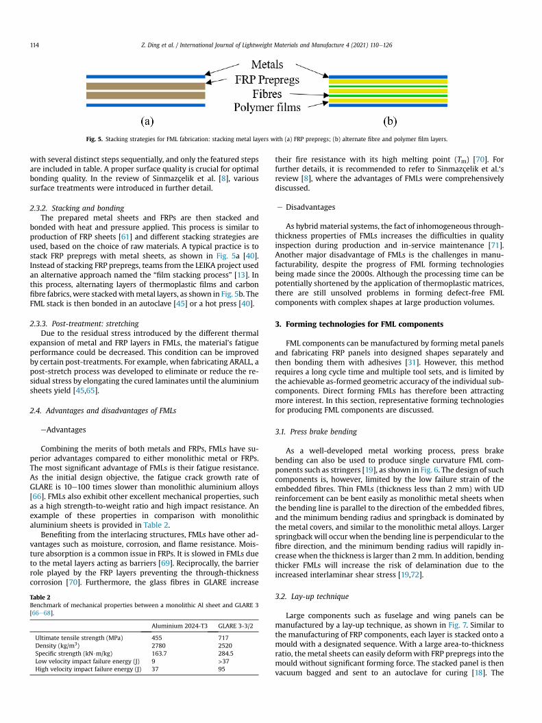
Fig. 5. Stacking strategies for FML fabrication: stacking metal layers with (a) FRP prepregs; (b) alternate fibre and polymer film layers.
Z. Ding et al. / International Journal of Lightweight Materials and Manufacture 4 (2021) 110e126114
with several distinct steps sequentially, and only the featured stepsare included in table. A proper surface quality is crucial for optimalbonding quality. In the review of Sinmazçelik et al. [8], varioussurface treatments were introduced in further detail.
2.3.2. Stacking and bondingThe prepared metal sheets and FRPs are then stacked and
bonded with heat and pressure applied. This process is similar toproduction of FRP sheets [61] and different stacking strategies areused, based on the choice of raw materials. A typical practice is tostack FRP prepregs with metal sheets, as shown in Fig. 5a [40].Instead of stacking FRP prepregs, teams from the LEIKA project usedan alternative approach named the “film stacking process” [13]. Inthis process, alternating layers of thermoplastic films and carbonfibre fabrics, were stackedwithmetal layers, as shown in Fig. 5b. TheFML stack is then bonded in an autoclave [45] or a hot press [40].
2.3.3. Post-treatment: stretchingDue to the residual stress introduced by the different thermal
expansion of metal and FRP layers in FMLs, the material's fatigueperformance could be decreased. This condition can be improvedby certain post-treatments. For example, when fabricating ARALL, apost-stretch process was developed to eliminate or reduce the re-sidual stress by elongating the cured laminates until the aluminiumsheets yield [45,65].
2.4. Advantages and disadvantages of FMLs
eAdvantages
Combining the merits of both metals and FRPs, FMLs have su-perior advantages compared to either monolithic metal or FRPs.The most significant advantage of FMLs is their fatigue resistance.As the initial design objective, the fatigue crack growth rate ofGLARE is 10e100 times slower than monolithic aluminium alloys[66]. FMLs also exhibit other excellent mechanical properties, suchas a high strength-to-weight ratio and high impact resistance. Anexample of these properties in comparison with monolithicaluminium sheets is provided in Table 2.
Benefiting from the interlacing structures, FMLs have other ad-vantages such as moisture, corrosion, and flame resistance. Mois-ture absorption is a common issue in FRPs. It is slowed in FMLs dueto the metal layers acting as barriers [69]. Reciprocally, the barrierrole played by the FRP layers preventing the through-thicknesscorrosion [70]. Furthermore, the glass fibres in GLARE increase
Table 2Benchmark of mechanical properties between a monolithic Al sheet and GLARE 3[66e68].
Aluminium 2024-T3 GLARE 3-3/2
Ultimate tensile strength (MPa) 455 717Density (kg/m3) 2780 2520Specific strength (kN$m/kg) 163.7 284.5Low velocity impact failure energy (J) 9 >37High velocity impact failure energy (J) 37 95
their fire resistance with its high melting point (Tm) [70]. Forfurther details, it is recommended to refer to Sinmazçelik et al.‘sreview [8], where the advantages of FMLs were comprehensivelydiscussed.
e Disadvantages
As hybrid material systems, the fact of inhomogeneous through-thickness properties of FMLs increases the difficulties in qualityinspection during production and in-service maintenance [71].Another major disadvantage of FMLs is the challenges in manu-facturability, despite the progress of FML forming technologiesbeing made since the 2000s. Although the processing time can bepotentially shortened by the application of thermoplastic matrices,there are still unsolved problems in forming defect-free FMLcomponents with complex shapes at large production volumes.
3. Forming technologies for FML components
FML components can be manufactured by forming metal panelsand fabricating FRP panels into designed shapes separately andthen bonding them with adhesives [31]. However, this methodrequires a long cycle time and multiple tool sets, and is limited bythe achievable as-formed geometric accuracy of the individual sub-components. Direct forming FMLs has therefore been attractingmore interest. In this section, representative forming technologiesfor producing FML components are discussed.
3.1. Press brake bending
As a well-developed metal working process, press brakebending can also be used to produce single curvature FML com-ponents such as stringers [19], as shown in Fig. 6. The design of suchcomponents is, however, limited by the low failure strain of theembedded fibres. Thin FMLs (thickness less than 2 mm) with UDreinforcement can be bent easily as monolithic metal sheets whenthe bending line is parallel to the direction of the embedded fibres,and the minimum bending radius and springback is dominated bythe metal covers, and similar to the monolithic metal alloys. Largerspringback will occur when the bending line is perpendicular to thefibre direction, and the minimum bending radius will rapidly in-creasewhen the thickness is larger than 2mm. In addition, bendingthicker FMLs will increase the risk of delamination due to theincreased interlaminar shear stress [19,72].
3.2. Lay-up technique
Large components such as fuselage and wing panels can bemanufactured by a lay-up technique, as shown in Fig. 7. Similar tothe manufacturing of FRP components, each layer is stacked onto amould with a designated sequence. With a large area-to-thicknessratio, the metal sheets can easily deformwith FRP prepregs into themould without significant forming force. The stacked panel is thenvacuum bagged and sent to an autoclave for curing [18]. The
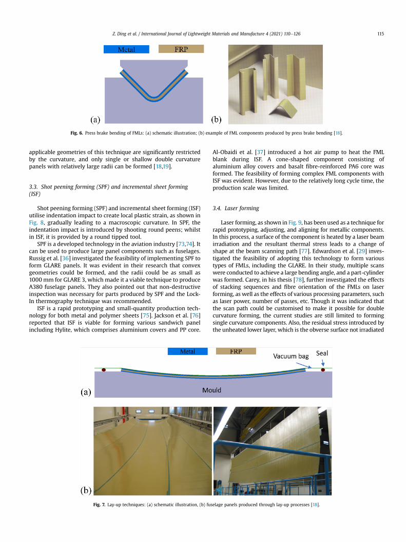
Fig. 6. Press brake bending of FMLs: (a) schematic illustration; (b) example of FML components produced by press brake bending [18].
Z. Ding et al. / International Journal of Lightweight Materials and Manufacture 4 (2021) 110e126 115
applicable geometries of this technique are significantly restrictedby the curvature, and only single or shallow double curvaturepanels with relatively large radii can be formed [18,19].
3.3. Shot peening forming (SPF) and incremental sheet forming(ISF)
Shot peening forming (SPF) and incremental sheet forming (ISF)utilise indentation impact to create local plastic strain, as shown inFig. 8, gradually leading to a macroscopic curvature. In SPF, theindentation impact is introduced by shooting round peens; whilstin ISF, it is provided by a round tipped tool.
SPF is a developed technology in the aviation industry [73,74]. Itcan be used to produce large panel components such as fuselages.Russig et al. [36] investigated the feasibility of implementing SPF toform GLARE panels. It was evident in their research that convexgeometries could be formed, and the radii could be as small as1000mm for GLARE 3, which made it a viable technique to produceA380 fuselage panels. They also pointed out that non-destructiveinspection was necessary for parts produced by SPF and the Lock-In thermography technique was recommended.
ISF is a rapid prototyping and small-quantity production tech-nology for both metal and polymer sheets [75]. Jackson et al. [76]reported that ISF is viable for forming various sandwich panelincluding Hylite, which comprises aluminium covers and PP core.
Fig. 7. Lay-up techniques: (a) schematic illustration, (b) fus
Al-Obaidi et al. [37] introduced a hot air pump to heat the FMLblank during ISF. A cone-shaped component consisting ofaluminium alloy covers and basalt fibre-reinforced PA6 core wasformed. The feasibility of forming complex FML components withISF was evident. However, due to the relatively long cycle time, theproduction scale was limited.
3.4. Laser forming
Laser forming, as shown in Fig. 9, has been used as a technique forrapid prototyping, adjusting, and aligning for metallic components.In this process, a surface of the component is heated by a laser beamirradiation and the resultant thermal stress leads to a change ofshape at the beam scanning path [77]. Edwardson et al. [29] inves-tigated the feasibility of adopting this technology to form varioustypes of FMLs, including the GLARE. In their study, multiple scanswere conducted to achieve a large bending angle, and a part-cylinderwas formed. Carey, in his thesis [78], further investigated the effectsof stacking sequences and fibre orientation of the FMLs on laserforming, as well as the effects of various processing parameters, suchas laser power, number of passes, etc. Though it was indicated thatthe scan path could be customised to make it possible for doublecurvature forming, the current studies are still limited to formingsingle curvature components. Also, the residual stress introduced bythe unheated lower layer, which is the obverse surface not irradiated
elage panels produced through lay-up processes [18].
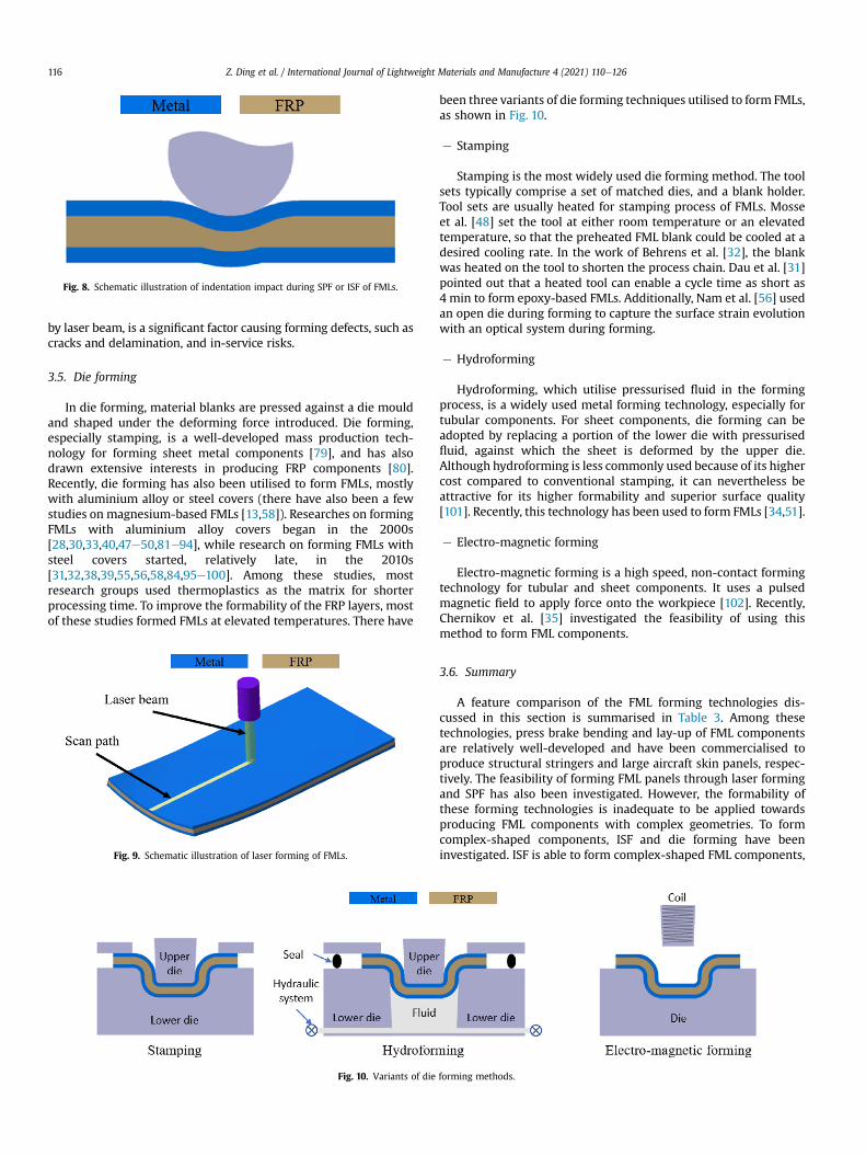
Fig. 8. Schematic illustration of indentation impact during SPF or ISF of FMLs.
Z. Ding et al. / International Journal of Lightweight Materials and Manufacture 4 (2021) 110e126116
by laser beam, is a significant factor causing forming defects, such ascracks and delamination, and in-service risks.
3.5. Die forming
In die forming, material blanks are pressed against a die mouldand shaped under the deforming force introduced. Die forming,especially stamping, is a well-developed mass production tech-nology for forming sheet metal components [79], and has alsodrawn extensive interests in producing FRP components [80].Recently, die forming has also been utilised to form FMLs, mostlywith aluminium alloy or steel covers (there have also been a fewstudies on magnesium-based FMLs [13,58]). Researches on formingFMLs with aluminium alloy covers began in the 2000s[28,30,33,40,47e50,81e94], while research on forming FMLs withsteel covers started, relatively late, in the 2010s[31,32,38,39,55,56,58,84,95e100]. Among these studies, mostresearch groups used thermoplastics as the matrix for shorterprocessing time. To improve the formability of the FRP layers, mostof these studies formed FMLs at elevated temperatures. There have
Fig. 9. Schematic illustration of laser forming of FMLs.
Fig. 10. Variants of die
been three variants of die forming techniques utilised to form FMLs,as shown in Fig. 10.
e Stamping
Stamping is the most widely used die forming method. The toolsets typically comprise a set of matched dies, and a blank holder.Tool sets are usually heated for stamping process of FMLs. Mosseet al. [48] set the tool at either room temperature or an elevatedtemperature, so that the preheated FML blank could be cooled at adesired cooling rate. In the work of Behrens et al. [32], the blankwas heated on the tool to shorten the process chain. Dau et al. [31]pointed out that a heated tool can enable a cycle time as short as4 min to form epoxy-based FMLs. Additionally, Nam et al. [56] usedan open die during forming to capture the surface strain evolutionwith an optical system during forming.
e Hydroforming
Hydroforming, which utilise pressurised fluid in the formingprocess, is a widely used metal forming technology, especially fortubular components. For sheet components, die forming can beadopted by replacing a portion of the lower die with pressurisedfluid, against which the sheet is deformed by the upper die.Although hydroforming is less commonly used because of its highercost compared to conventional stamping, it can nevertheless beattractive for its higher formability and superior surface quality[101]. Recently, this technology has been used to form FMLs [34,51].
e Electro-magnetic forming
Electro-magnetic forming is a high speed, non-contact formingtechnology for tubular and sheet components. It uses a pulsedmagnetic field to apply force onto the workpiece [102]. Recently,Chernikov et al. [35] investigated the feasibility of using thismethod to form FML components.
3.6. Summary
A feature comparison of the FML forming technologies dis-cussed in this section is summarised in Table 3. Among thesetechnologies, press brake bending and lay-up of FML componentsare relatively well-developed and have been commercialised toproduce structural stringers and large aircraft skin panels, respec-tively. The feasibility of forming FML panels through laser formingand SPF has also been investigated. However, the formability ofthese forming technologies is inadequate to be applied towardsproducing FML components with complex geometries. To formcomplex-shaped components, ISF and die forming have beeninvestigated. ISF is able to form complex-shaped FML components,
forming methods.
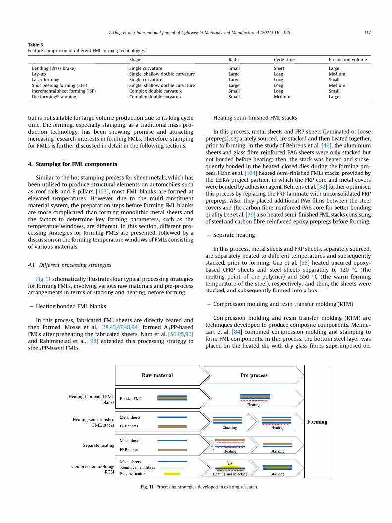
Table 3Feature comparison of different FML forming technologies.
Shape Radii Cycle time Production volume
Bending (Press brake) Single curvature Small Short LargeLay-up Single, shallow double curvature Large Long MediumLaser forming Single curvature Large Long SmallShot peening forming (SPF) Single, shallow double curvature Large Long MediumIncremental sheet forming (ISF) Complex double curvature Small Long SmallDie forming/Stamping Complex double curvature Small Medium Large
Z. Ding et al. / International Journal of Lightweight Materials and Manufacture 4 (2021) 110e126 117
but is not suitable for large volume production due to its long cycletime. Die forming, especially stamping, as a traditional mass pro-duction technology, has been showing promise and attractingincreasing research interests in forming FMLs. Therefore, stampingfor FMLs is further discussed in detail in the following sections.
4. Stamping for FML components
Similar to the hot stamping process for sheet metals, which hasbeen utilised to produce structural elements on automobiles suchas roof rails and B-pillars [103], most FML blanks are formed atelevated temperatures. However, due to the multi-constituentmaterial system, the preparation steps before forming FML blanksare more complicated than forming monolithic metal sheets andthe factors to determine key forming parameters, such as thetemperature windows, are different. In this section, different pro-cessing strategies for forming FMLs are presented, followed by adiscussion on the forming temperaturewindows of FMLs consistingof various materials.
4.1. Different processing strategies
Fig.11 schematically illustrates four typical processing strategiesfor forming FMLs, involving various raw materials and pre-processarrangements in terms of stacking and heating, before forming.
e Heating bonded FML blanks
In this process, fabricated FML sheets are directly heated andthen formed. Mosse et al. [28,40,47,48,94] formed Al/PP-basedFMLs after preheating the fabricated sheets. Nam et al. [56,95,96]and Rahiminejad et al. [98] extended this processing strategy tosteel/PP-based FMLs.
Fig. 11. Processing strategies dev
e Heating semi-finished FML stacks
In this process, metal sheets and FRP sheets (laminated or looseprepregs), separately sourced, are stacked and then heated together,prior to forming. In the study of Behrens et al. [49], the aluminiumsheets and glass fibre-reinforced PA6 sheets were only stacked butnot bonded before heating; then, the stack was heated and subse-quently bonded in the heated, closed dies during the forming pro-cess. Hahn et al. [104] heated semi-finished FMLs stacks, provided bythe LEIKA project partner, in which the FRP core and metal coverswere bonded by adhesion agent. Behrens et al. [32] further optimisedthis process by replacing the FRP laminate with unconsolidated FRPprepregs. Also, they placed additional PA6 films between the steelcovers and the carbon fibre-reinforced PA6 core for better bondingquality. Lee et al. [39] also heated semi-finished FML stacks consistingof steel and carbon fibre-reinforced epoxy prepregs before forming.
e Separate heating
In this process, metal sheets and FRP sheets, separately sourced,are separately heated to different temperatures and subsequentlystacked, prior to forming. Guo et al. [55] heated uncured epoxy-based CFRP sheets and steel sheets separately to 120 �C (themelting point of the polymer) and 550 �C (the warm formingtemperature of the steel), respectively; and then, the sheets werestacked, and subsequently formed into a box.
e Compression molding and resin transfer molding (RTM)
Compression molding and resin transfer molding (RTM) aretechniques developed to produce composite components. Menne-cart et al. [84] combined compression molding and stamping toform FML components. In this process, the bottom steel layer wasplaced on the heated die with dry glass fibres superimposed on.
eloped in existing research.
Z. Ding et al. / International Journal of Lightweight Materials and Manufacture 4 (2021) 110e126118
Thermoplastic liquid was then applied onto the blank before thetop steel layer being stacked, after which the stacked sheet wasformed. An alternative method developed by themwas to combinethe T-RTM (RTM with thermoplastic matrix) and stamping,whereby the thermoplastic liquid was injected through concentricholes on the upper die and the top steel layer, whichwas stacked onthe top of the bottom steel and fibre layers prior to transferring tothe tool. The polymer can also be injected between themetal sheetsthrough the edges of the stacked blanks. In addition, they alsomentioned that the injection can take place before, during, or afterforming [33,84]. A special thermoplastic liquid, named Elium, wasused in this process [84], but other polymers, such as cast-PA6(PA6G) and polymethyl-methacrylate (PMMA), were also sug-gested to be potential matrix solutions [33].
In the above-mentioned strategies, heating fabricated FMLlaminates is not viable for forming thermoset-based FMLs, becausethermoset polymers cannot be reshaped after curing. The strategiesof heating semi-finished FML stacks and heating separate metaland FRP sheets can shorten the overall production chain, by skip-ping the step of fabricating FML sheets; also, these two strategiescan be adopted to form both thermoset-based and thermoplastic-based FMLs. In addition, separate heating allows the thermo-mechanical behaviours of metal constituents to be taken intoconsideration and offers an opportunity of improving the form-ability and as-formed strength of FML components. Compressionmolding and RTM are also viable strategies for forming boththermoset-based and thermoplastic-based FMLs, provided thepolymer used has a suitable viscosity.
After forming, the part is usually dwelled in the closed die forbonding. In some studies, post-form thermal treatment was per-formed to increase the bonding quality and efficiency. Forthermoset-based FMLs, Guo et al. [55] heated the die to the epoxycuring temperature (150�C) for curing and bonding. For formingthermoplastic-based FMLs, Behrens et al. [32] cooled the die andthe components to establish the bonding between the metal coversand FRP core. As they further mentioned, geometric accuracy canalso be improved, benefitting from the post-form thermal treat-ment. Thus, further investigation on the effect of cooling rate andremoval temperature was suggested.
4.2. Forming temperature windows
The forming temperature is considered to be the most importantprocess parameter in FML forming. It is noted that the temperature
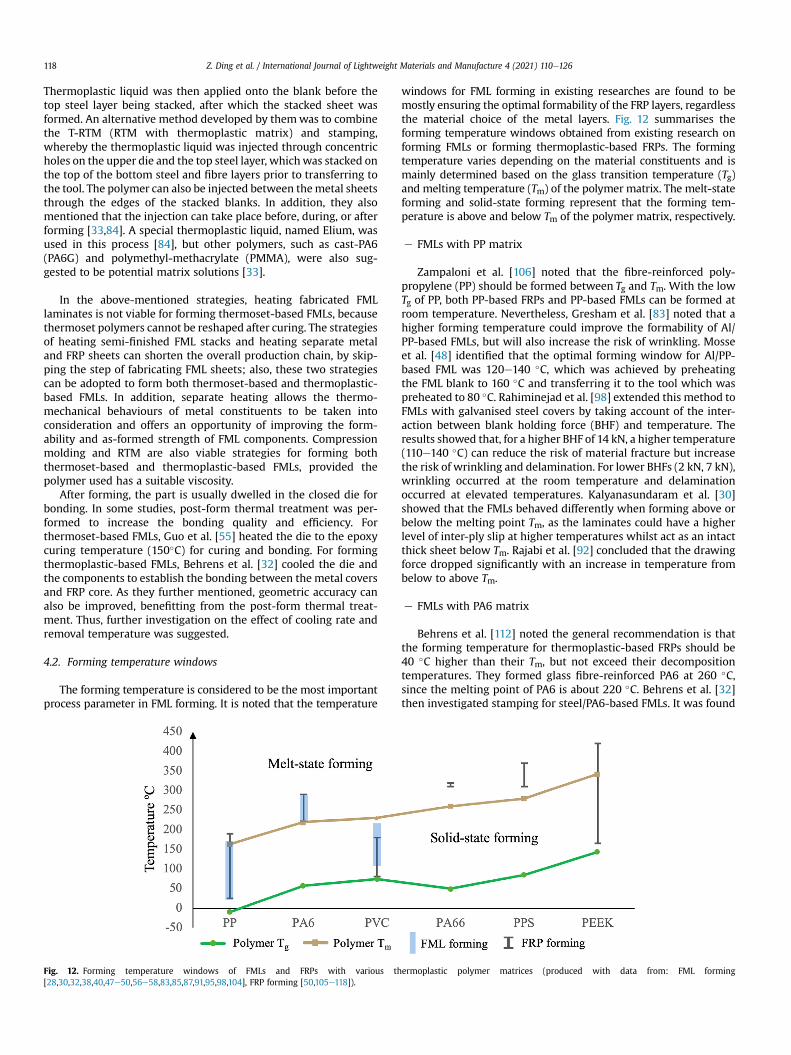
Fig. 12. Forming temperature windows of FMLs and FRPs with various th[28,30,32,38,40,47e50,56e58,83,85,87,91,95,98,104], FRP forming [50,105e118]).
windows for FML forming in existing researches are found to bemostly ensuring the optimal formability of the FRP layers, regardlessthe material choice of the metal layers. Fig. 12 summarises theforming temperature windows obtained from existing research onforming FMLs or forming thermoplastic-based FRPs. The formingtemperature varies depending on the material constituents and ismainly determined based on the glass transition temperature (Tg)and melting temperature (Tm) of the polymer matrix. The melt-stateforming and solid-state forming represent that the forming tem-perature is above and below Tm of the polymer matrix, respectively.
e FMLs with PP matrix
Zampaloni et al. [106] noted that the fibre-reinforced poly-propylene (PP) should be formed between Tg and Tm. With the lowTg of PP, both PP-based FRPs and PP-based FMLs can be formed atroom temperature. Nevertheless, Gresham et al. [83] noted that ahigher forming temperature could improve the formability of Al/PP-based FMLs, but will also increase the risk of wrinkling. Mosseet al. [48] identified that the optimal forming window for Al/PP-based FML was 120e140 �C, which was achieved by preheatingthe FML blank to 160 �C and transferring it to the tool which waspreheated to 80 �C. Rahiminejad et al. [98] extended this method toFMLs with galvanised steel covers by taking account of the inter-action between blank holding force (BHF) and temperature. Theresults showed that, for a higher BHF of 14 kN, a higher temperature(110e140 �C) can reduce the risk of material fracture but increasethe risk of wrinkling and delamination. For lower BHFs (2 kN, 7 kN),wrinkling occurred at the room temperature and delaminationoccurred at elevated temperatures. Kalyanasundaram et al. [30]showed that the FMLs behaved differently when forming above orbelow the melting point Tm, as the laminates could have a higherlevel of inter-ply slip at higher temperatures whilst act as an intactthick sheet below Tm. Rajabi et al. [92] concluded that the drawingforce dropped significantly with an increase in temperature frombelow to above Tm.
e FMLs with PA6 matrix
Behrens et al. [112] noted the general recommendation is thatthe forming temperature for thermoplastic-based FRPs should be40 �C higher than their Tm, but not exceed their decompositiontemperatures. They formed glass fibre-reinforced PA6 at 260 �C,since the melting point of PA6 is about 220 �C. Behrens et al. [32]then investigated stamping for steel/PA6-based FMLs. It was found
ermoplastic polymer matrices (produced with data from: FML forming
Z. Ding et al. / International Journal of Lightweight Materials and Manufacture 4 (2021) 110e126 119
that the temperature for optimal bonding quality was 250 �C, whileexcessive temperature (280 �C) would result in outgassing of thepolymer and create gas cavities in the matrix. In addition, Hahnet al. [104] determined that insufficient temperature (160 �C) couldnot allow desirable inter-ply slip during bending, and a preheatingtemperature of 240 �C was used in their following experiments.
e FMLs with PVC matrix
Zal et al. [50] investigated the forming temperature for Al/polyvinyl-chloride (PVC)-based FMLs. Due to PVC's sensitivity totemperature, the temperature window was kept under 220 �C toavoid degradation. They also defined forming temperature for PVC-based FMLs should be 20 �C higher than for PVC-based FRPs. Itshould be noted that the melting point shown in Fig. 12 is actuallythe consolidation temperature (230 �C) used by Zal et al. [50].Because there are various PVCs with different melting points, theauthors did not specify the melting point of the PVC they used.
e FMLs with thermoset matrix
For stamping thermoset-based FMLs, warm forming was alsoconsidered as the matrix needs to be cured at an elevated tem-perature [31]. Guo et al. [55] separately heated the prepregs andmetal sheets for better formability (as mentioned in section 4.1),and successfully formed a box-shaped component. Heggemann andHomberg [99] reported that local preheating improved the formingquality by better regulating the polymer flow during forming.
e Forming of other FRPs investigated
Forming temperature windows for FRPs based on other popularthermoplastic matrices, such as PA66 [113], PPS [114,115] and PEEK[116e118], have also been studied. It can be seen that all of themcould be formed above themelting point. In addition, the feasibilityof forming PEEK-based FRP at solid state was investigated [118].Considering the relatively high melting temperature, solid-stateforming could be an attractive and cost-effective solution forPEEK-based FRPs. However, studies of FMLs based on these polymermatrices have not been found.
It can be summarised that the temperature windows applied inFML forming were mostly determined by the polymer matrix in
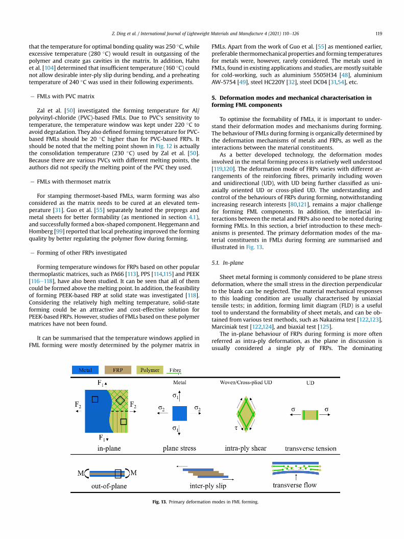
Fig. 13. Primary deformation
FMLs. Apart from the work of Guo et al. [55] as mentioned earlier,preferable thermomechanical properties and forming temperaturesfor metals were, however, rarely considered. The metals used inFMLs, found in existing applications and studies, aremostly suitablefor cold-working, such as aluminium 5505H34 [48], aluminiumAW-5754 [49], steel HC220Y [32], steel DC04 [31,54], etc.
5. Deformation modes and mechanical characterisation informing FML components
To optimise the formability of FMLs, it is important to under-stand their deformation modes and mechanisms during forming.The behaviour of FMLs during forming is organically determined bythe deformation mechanisms of metals and FRPs, as well as theinteractions between the material constituents.
As a better developed technology, the deformation modesinvolved in the metal forming process is relatively well understood[119,120]. The deformation mode of FRPs varies with different ar-rangements of the reinforcing fibres, primarily including wovenand unidirectional (UD), with UD being further classified as uni-axially oriented UD or cross-plied UD. The understanding andcontrol of the behaviours of FRPs during forming, notwithstandingincreasing research interests [80,121], remains a major challengefor forming FML components. In addition, the interfacial in-teractions between themetal and FRPs also need to be noted duringforming FMLs. In this section, a brief introduction to these mech-anisms is presented. The primary deformation modes of the ma-terial constituents in FMLs during forming are summarised andillustrated in Fig. 13.
5.1. In-plane
Sheet metal forming is commonly considered to be plane stressdeformation, where the small stress in the direction perpendicularto the blank can be neglected. The material mechanical responsesto this loading condition are usually characterised by uniaxialtensile tests; in addition, forming limit diagram (FLD) is a usefultool to understand the formability of sheet metals, and can be ob-tained from various test methods, such as Nakazima test [122,123],Marciniak test [122,124], and biaxial test [125].
The in-plane behaviour of FRPs during forming is more oftenreferred as intra-ply deformation, as the plane in discussion isusually considered a single ply of FRPs. The dominating
modes in FML forming.
Z. Ding et al. / International Journal of Lightweight Materials and Manufacture 4 (2021) 110e126120
deformation mode of woven fabrics or cross-plied UD laminatesduring forming is intra-ply shear, corresponding to the reor-ientation of nearly-inextensible fibres [126]. Transverse tension inuniaxially oriented UD prepregs can be a dominating deformationmode during forming as the material under transverse tension isless stiff than that under shear [127]. In addition, intra-ply longi-tudinal tension of all FRPs is considered a less important factor dueto small elongation at break of fibres.
For woven fabrics, intra-ply shear is considered to be the pri-mary deformation mode in forming [128,129]. During forming,woven fibres rotate in a ‘pin-jointed’ fashion under shear load.When the locking angle is reached, where further shear and rota-tion is impossible, compressed fibres would experience buckling orout-of-plane deformation and eventually result in macroscopicwrinkling [130]. In addition, the rotated fibres reduce space be-tween them [131], where local thickness increases caused by ma-terial incompressibility can be expected [132]. For uniaxiallyoriented UD prepregs, intra-ply shear often refers to the longitu-dinal shear in the plane parallel to the ply surface, despite the ex-istence of transverse shear through the thickness [140]. Potter [127]reported that, in uniaxially oriented UD prepregs, the materialunder shear deformation mode was ten times stiffer than that intransverse tension at room temperature. Therefore, it is difficult tobalance material flow in forming UD prepregs with uniaxially ori-ented plies. Instead, forming cross-plied UD sheets is more likely tobe adopted. For cross-plied UD sheets, Potter [134] further notedthat their deformation modes showed similarity to the wovenfabric, thus could be predicted by ‘pin-jointed’ model which isdeveloped for woven fabrics.
The intra-ply shear behaviour is usually characterised throughbias-extension or picture frame tests for woven fabrics [128,135].Bias-extension test has also been used to characterise the intra-plyshear behaviour for cross-plied UD sheets [134]. For uniaxiallyorientated UD sheets, McGuinness and Br�adaigh performed pictureframe tests by supporting the UD sheet specimen with vacuumeddiaphragms. However, the effect of diaphragms cannot bemeasured to determine the accurate response of the UD sheets.Potter [127] performed off-axis test for unsupported UD plies. It isnoted that when the angle between the fibre orientation andloading direction is larger than 15�, the dominating deformationmode would be transverse tension rather than intra-ply shear. Inaddition, Haanappel and Akkerman [136] conducted a torsional bartest to characterise the intra-ply shear of uniaxially oriented UDsheets. Furthermore, although the standardised V-notched railshear method [137] was used to test the in-plane shear of FRPs[138], no literature has been found to use this method for charac-terising their behaviours during forming.
5.2. Out-of-plane
Out-of-plane bending is another important deformation char-acteristic in forming both sheet metals and FRPs. The bendingbehaviour in sheet metal forming is relatively well understood[139]. The bending behaviour in forming a FRP prepreg, however,has received little attention as their bending resistance is orders ofmagnitude lower than intra-ply shear resistance [128]. For forminglaminated materials including FRP sheets and FMLs, inter-layerinteractions and through-thickness behaviour, which primarilyrepresented by inter-ply slip and transverse flow, need to be takeninto consideration.
Inter-ply slip is an important deformation mode to accommo-date the bending of laminated materials, especially during solid-state forming. By allowing relative movement between layers,inter-ply slip can reduce the wrinkling of the inner layer of alaminate [104,128,140] and cracking of the outer layer [104]. There
have been extensive studies on tribology to characterise the ply-plyand tool-ply slip in forming FRPs. In particular, the results fromtool-ply tests can be studied to better understand the interfacialcharacteristics between the metal and FRP layers in FMLs. Varioustest methods, including ‘pull-out’ and ‘pull-through’ tests, havebeen developed to characterise the interfacial behaviours informing FRPs. Recently, a benchmark study of several different testmethods has been conducted by Saches et al. [141] with PP-basedFRPs. In addition, Mosse et al. [81] conducted a ‘pull-out’ testwith a specially fabricated FML specimen to understand the shearbehaviour between the bonded aluminium and glass fibre-reinforced PP layers.
Transverse flow is also an important deformation mode,particularlywhen forming FMLswith uniaxially oriented UD core atmelt-state. During forming, the bent metal covers induce unevennormal pressure onto the FRP core at the bending area, where thepolymer could be squeezed outwards transversely. This is also anobserved phenomenon when fabricating FRP sheets, where thenormal pressure induces a pressure gradient along both of thetransverse and longitudinal fibre directions. As a consequence, fi-bres will flow with the polymer in the transverse direction[140,142], whereas only polymer will be squeezed in the longitu-dinal direction as the fibres are inextensible [142]. Murtagh andMallon [140] mentioned that transverse flow in cross-plied UDprepregs or woven fabrics is limited. They also mentioned that thetransverse flow can be investigated using parallel-plate flowsqueezing apparatus.
6. Defects and challenges in forming FML components
FML forming technologies are under developing with manychallenges encountered. There are many common defects, despitetheir different deformationmodes, in forming FMLs andmonolithicmetal sheets, such as springback, wrinkling, cracking, and thicknessvariation. Additionally, as a multi-layer material like FRP sheets,delamination can occur in forming FMLs. These defects duringforming are the result of the interaction between various factors,including product geometrical design and processing parameterssuch as temperature, BHF, feed rate, etc. In particular, the stackingarrangement of the layers in FMLs can also affect the formingquality. In this section, typical defects occurred during FML formingand research on their countermeasures are discussed.
6.1. Springback
Springback, as shown in Fig. 14a, is a common defect in sheetmetal forming and has been attracting continued research interests[143]. In metal forming, it is caused by elastic recovery which re-sults in geometric inaccuracy, i.e. springback, after forming, and canbe difficult to be reduced or eliminated. To improve the geometricaccuracy of the products, over-bending the part or increasing localplastic deformation at the radii region is usually considered duringthe forming process [119]. In FRP forming, however, spring-in oc-curs because of FRP's anisotropic material properties [144]. Behrenset al. [32] found that the springback effect in metal forming and thespring-in effect of FRP forming occurred at the same time andweakened the counterparty, which would lead to a smaller geo-metric deviation. Hahn et al. [104] explained that with a certainamount of dwell time, the solidified FRP core can reduce the overallspringback when forming FMLs. Mosse et al. [48] reported that Al/PP-FMLs showed 75% less geometric deviation compared tomonolithic aluminiumwhen forming a channel. Guo et al. [55] alsoreported a smaller shape error in forming FMLs compared tomonolithic steels. Despite these reported positive results, themulti-material systems also increase the complexity of
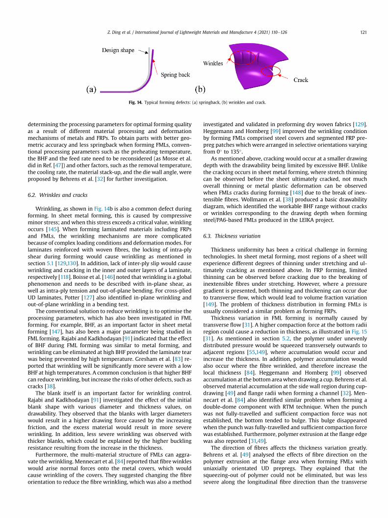
Fig. 14. Typical forming defects: (a) springback, (b) wrinkles and crack.
Z. Ding et al. / International Journal of Lightweight Materials and Manufacture 4 (2021) 110e126 121
determining the processing parameters for optimal forming qualityas a result of different material processing and deformationmechanisms of metals and FRPs. To obtain parts with better geo-metric accuracy and less springback when forming FMLs, conven-tional processing parameters such as the preheating temperature,the BHF and the feed rate need to be reconsidered (as Mosse et al.did in Ref. [47]) and other factors, such as the removal temperature,the cooling rate, the material stack-up, and the die wall angle, wereproposed by Behrens et al. [32] for further investigation.
6.2. Wrinkles and cracks
Wrinkling, as shown in Fig. 14b is also a common defect duringforming. In sheet metal forming, this is caused by compressiveminor stress; and when this stress exceeds a critical value, winklingoccurs [145]. When forming laminated materials including FRPsand FMLs, the wrinkling mechanisms are more complicatedbecause of complex loading conditions and deformationmodes. Forlaminates reinforced with woven fibres, the locking of intra-plyshear during forming would cause wrinkling as mentioned insection 5.1 [129,130]. In addition, lack of inter-ply slip would causewrinkling and cracking in the inner and outer layers of a laminate,respectively [118]. Boisse et al. [146] noted that wrinkling is a globalphenomenon and needs to be described with in-plane shear, aswell as intra-ply tension and out-of-plane bending. For cross-pliedUD laminates, Potter [127] also identified in-plane wrinkling andout-of-plane wrinkling in a bending test.
The conventional solution to reduce wrinkling is to optimise theprocessing parameters, which has also been investigated in FMLforming. For example, BHF, as an important factor in sheet metalforming [147], has also been a major parameter being studied inFML forming. Rajabi and Kadkhodayan [91] indicated that the effectof BHF during FML forming was similar to metal forming, andwrinkling can be eliminated at high BHF provided the laminate tearwas being prevented by high temperature. Gresham et al. [83] re-ported that wrinkling will be significantly more severe with a lowBHF at high temperatures. A common conclusion is that higher BHFcan reducewrinkling, but increase the risks of other defects, such ascracks [38].
The blank itself is an important factor for wrinkling control.Rajabi and Kadkhodayan [91] investigated the effect of the initialblank shape with various diameter and thickness values, ondrawability. They observed that the blanks with larger diameterswould result in a higher drawing force caused by the increasingfriction, and the excess material would result in more severewrinkling. In addition, less severe wrinkling was observed withthicker blanks, which could be explained by the higher bucklingresistance resulting from the increase in the thickness.
Furthermore, the multi-material structure of FMLs can aggra-vate thewrinkling. Mennecart et al. [84] reported that fibrewinkleswould arise normal forces onto the metal covers, which wouldcause wrinkling of the covers. They suggested changing the fibreorientation to reduce the fibre wrinkling, which was also a method
investigated and validated in preforming dry woven fabrics [129].Heggemann and Homberg [99] improved the wrinkling conditionby forming FMLs comprised steel covers and segmented FRP pre-preg patches which were arranged in selective orientations varyingfrom 0� to 135�.
As mentioned above, cracking would occur at a smaller drawingdepth with the drawability being limited by excessive BHF. Unlikethe cracking occurs in sheet metal forming, where stretch thinningcan be observed before the sheet ultimately cracked, not muchoverall thinning or metal plastic deformation can be observedwhen FMLs cracks during forming [148] due to the break of inex-tensible fibres. Wollmann et al. [38] produced a basic drawabilitydiagram, which identified the workable BHF range without cracksor wrinkles corresponding to the drawing depth when formingsteel/PA6-based FMLs produced in the LEIKA project.
6.3. Thickness variation
Thickness uniformity has been a critical challenge in formingtechnologies. In sheet metal forming, most regions of a sheet willexperience different degrees of thinning under stretching and ul-timately cracking as mentioned above. In FRP forming, limitedthinning can be observed before cracking due to the breaking ofinextensible fibres under stretching. However, where a pressuregradient is presented, both thinning and thickening can occur dueto transverse flow, which would lead to volume fraction variation[149]. The problem of thickness distribution in forming FMLs isusually considered a similar problem as forming FRPs.
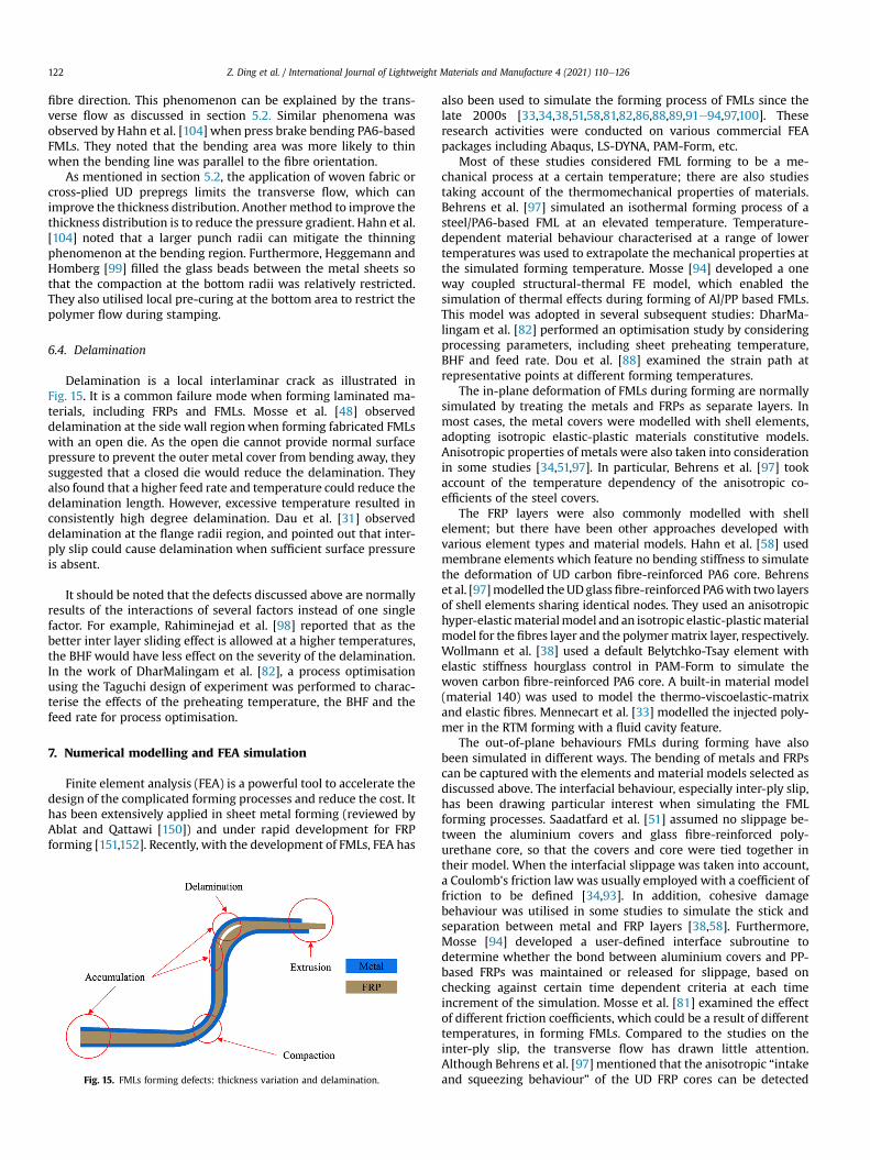
Thickness variation in FML forming is normally caused bytransverse flow [31]. A higher compaction force at the bottom radiiregion could cause a reduction in thickness, as illustrated in Fig. 15[31]. As mentioned in section 5.2, the polymer under unevenlydistributed pressure would be squeezed transversely outwards toadjacent regions [55,149], where accumulation would occur andincrease the thickness. In addition, polymer accumulation wouldalso occur where the fibre wrinkled, and therefore increase thelocal thickness [84]. Heggemann and Homberg [99] observedaccumulation at the bottom areawhen drawing a cup. Behrens et al.observed material accumulation at the side wall region during cup-drawing [49] and flange radii when forming a channel [32]. Men-necart et al. [84] also identified similar problem when forming adouble-dome component with RTM technique. When the punchwas not fully-travelled and sufficient compaction force was notestablished, the bottom tended to bulge. This bulge disappearedwhen the punchwas fully-travelled and sufficient compaction forcewas established. Furthermore, polymer extrusion at the flange edgewas also reported [31,49].
The direction of fibres affects the thickness variation greatly.Behrens et al. [49] analysed the effects of fibre direction on thepolymer extrusion at the flange area when forming FMLs withuniaxially orientated UD prepregs. They explained that thesqueezing-out of polymer could not be eliminated, but was lesssevere along the longitudinal fibre direction than the transverse
Z. Ding et al. / International Journal of Lightweight Materials and Manufacture 4 (2021) 110e126122
fibre direction. This phenomenon can be explained by the trans-verse flow as discussed in section 5.2. Similar phenomena wasobserved by Hahn et al. [104] when press brake bending PA6-basedFMLs. They noted that the bending area was more likely to thinwhen the bending line was parallel to the fibre orientation.
As mentioned in section 5.2, the application of woven fabric orcross-plied UD prepregs limits the transverse flow, which canimprove the thickness distribution. Another method to improve thethickness distribution is to reduce the pressure gradient. Hahn et al.[104] noted that a larger punch radii can mitigate the thinningphenomenon at the bending region. Furthermore, Heggemann andHomberg [99] filled the glass beads between the metal sheets sothat the compaction at the bottom radii was relatively restricted.They also utilised local pre-curing at the bottom area to restrict thepolymer flow during stamping.
6.4. Delamination
Delamination is a local interlaminar crack as illustrated inFig. 15. It is a common failure mode when forming laminated ma-terials, including FRPs and FMLs. Mosse et al. [48] observeddelamination at the side wall regionwhen forming fabricated FMLswith an open die. As the open die cannot provide normal surfacepressure to prevent the outer metal cover from bending away, theysuggested that a closed die would reduce the delamination. Theyalso found that a higher feed rate and temperature could reduce thedelamination length. However, excessive temperature resulted inconsistently high degree delamination. Dau et al. [31] observeddelamination at the flange radii region, and pointed out that inter-ply slip could cause delamination when sufficient surface pressureis absent.
It should be noted that the defects discussed above are normallyresults of the interactions of several factors instead of one singlefactor. For example, Rahiminejad et al. [98] reported that as thebetter inter layer sliding effect is allowed at a higher temperatures,the BHF would have less effect on the severity of the delamination.In the work of DharMalingam et al. [82], a process optimisationusing the Taguchi design of experiment was performed to charac-terise the effects of the preheating temperature, the BHF and thefeed rate for process optimisation.
7. Numerical modelling and FEA simulation
Finite element analysis (FEA) is a powerful tool to accelerate thedesign of the complicated forming processes and reduce the cost. Ithas been extensively applied in sheet metal forming (reviewed byAblat and Qattawi [150]) and under rapid development for FRPforming [151,152]. Recently, with the development of FMLs, FEA has
Fig. 15. FMLs forming defects: thickness variation and delamination.
also been used to simulate the forming process of FMLs since thelate 2000s [33,34,38,51,58,81,82,86,88,89,91e94,97,100]. Theseresearch activities were conducted on various commercial FEApackages including Abaqus, LS-DYNA, PAM-Form, etc.
Most of these studies considered FML forming to be a me-chanical process at a certain temperature; there are also studiestaking account of the thermomechanical properties of materials.Behrens et al. [97] simulated an isothermal forming process of asteel/PA6-based FML at an elevated temperature. Temperature-dependent material behaviour characterised at a range of lowertemperatures was used to extrapolate the mechanical properties atthe simulated forming temperature. Mosse [94] developed a oneway coupled structural-thermal FE model, which enabled thesimulation of thermal effects during forming of Al/PP based FMLs.This model was adopted in several subsequent studies: DharMa-lingam et al. [82] performed an optimisation study by consideringprocessing parameters, including sheet preheating temperature,BHF and feed rate. Dou et al. [88] examined the strain path atrepresentative points at different forming temperatures.
The in-plane deformation of FMLs during forming are normallysimulated by treating the metals and FRPs as separate layers. Inmost cases, the metal covers were modelled with shell elements,adopting isotropic elastic-plastic materials constitutive models.Anisotropic properties of metals were also taken into considerationin some studies [34,51,97]. In particular, Behrens et al. [97] tookaccount of the temperature dependency of the anisotropic co-efficients of the steel covers.
The FRP layers were also commonly modelled with shellelement; but there have been other approaches developed withvarious element types and material models. Hahn et al. [58] usedmembrane elements which feature no bending stiffness to simulatethe deformation of UD carbon fibre-reinforced PA6 core. Behrenset al. [97]modelled theUDglassfibre-reinforced PA6with two layersof shell elements sharing identical nodes. They used an anisotropichyper-elasticmaterialmodel and an isotropic elastic-plasticmaterialmodel for the fibres layer and the polymermatrix layer, respectively.Wollmann et al. [38] used a default Belytchko-Tsay element withelastic stiffness hourglass control in PAM-Form to simulate thewoven carbon fibre-reinforced PA6 core. A built-in material model(material 140) was used to model the thermo-viscoelastic-matrixand elastic fibres. Mennecart et al. [33] modelled the injected poly-mer in the RTM forming with a fluid cavity feature.
The out-of-plane behaviours FMLs during forming have alsobeen simulated in different ways. The bending of metals and FRPscan be captured with the elements and material models selected asdiscussed above. The interfacial behaviour, especially inter-ply slip,has been drawing particular interest when simulating the FMLforming processes. Saadatfard et al. [51] assumed no slippage be-tween the aluminium covers and glass fibre-reinforced poly-urethane core, so that the covers and core were tied together intheir model. When the interfacial slippage was taken into account,a Coulomb's friction law was usually employed with a coefficient offriction to be defined [34,93]. In addition, cohesive damagebehaviour was utilised in some studies to simulate the stick andseparation between metal and FRP layers [38,58]. Furthermore,Mosse [94] developed a user-defined interface subroutine todetermine whether the bond between aluminium covers and PP-based FRPs was maintained or released for slippage, based onchecking against certain time dependent criteria at each timeincrement of the simulation. Mosse et al. [81] examined the effectof different friction coefficients, which could be a result of differenttemperatures, in forming FMLs. Compared to the studies on theinter-ply slip, the transverse flow has drawn little attention.Although Behrens et al. [97] mentioned that the anisotropic “intakeand squeezing behaviour” of the UD FRP cores can be detected
Z. Ding et al. / International Journal of Lightweight Materials and Manufacture 4 (2021) 110e126 123
qualitatively with their “sharing nodes” technique, and Mennecartet al. [33] found a fairly good prediction of the bulging effect at thebottom area with the fluid cavity feature employed, the polymerflow cannot be captured accurately.
There has been a certain degree of progress in simulating FMLforming, and FEA has proven to be a useful tool to design, examineand optimise the forming process. With the current modellingtechniques as discussed above, most deformation modes duringFML forming, including the in-plane behaviour of the constitutinglayers, out-of-plane bending and inter-ply slip, can be captured.Therefore, FML deformation behaviours as well as various defects,such as wrinkling and excessive thickness reduction (or cracking),can be predicted; and forming quality can thus be evaluated andbetter analysed by examining certain simulation outputs, such asstrain path; however, the transverse flow cannot be accuratelycaptured with the current shell or membrane-based modellingtechniques. Therefore, the prediction of the thickness variationcaused by polymer flow remains a challenge.
8. Conclusions and future research trends
This review provides an extensive survey and appraisal of thestate-of-the-art FMLs and their forming technologies, with keyconclusions listed below:
(1) For the material constituents, it can be observed that thematerials for metal layers have been extended fromaluminium alloys to steels, which allows lower cost thuswider applications in the automotive industry. Thermoplas-tics have also been replacing thermoset polymers to enablefaster production and better recyclability.
(2) Bending of single-curvature stringers and lay-up of largepanels with shallow curvatures for FMLs have been relativelywell developed and there have been successful applicationsin the state-of-the-art airplanes. Alternative forming tech-nologies, such as shot peening forming (SPF), incrementalsheet forming (ISF), and laser forming, have been analysedand it was evident that they were feasible. However, theirlimitations in formability and/or productivity make them notthe best candidates for the high-volume production ofcomplex-shaped FML components.
(3) Stamp forming has shown promise for producing morecomplex-shaped FML components, such as deep drawnpanels. To achieve better formability, FMLs are usuallystamped at elevated temperatures. In addition, other pro-cessing parameters and their interactions have also beenconsidered to achieve optimal forming quality. So far, theforming temperature is primarily dependent on the glasstransition temperature and melting temperature of thepolymer matrix of an FML. The preferable thermomechanicalbehaviours and forming temperature windows of the metallayers are, however, rarely considered, due to the fact that themost alloys used for producing existing FML structures are ofthe grades for cold working.
(4) The formability of FMLs is determined by the deformationbehaviours of both the metal and FRP layers, as well as theirinterfacial interactions, during forming. Compared to metals,the understanding of the deformation mechanism of theFRPs and the metal-FRP interfacial behaviours is lessadequate; thus, forming defect-free FMLs remains a majorchallenge. Some defects, including thickness variationcaused by transverse flow and delamination, are similar tothe defects in FRP forming, which is also drawing significantresearch attention at the moment. To achieve optimalformability and as-formed quality of FML components, a
thorough understanding of their deformation mechanismsunder forming conditions is essential.
(5) Modelling and simulation technologies of FML formingprocesses are being developed alongside the FML formingtechnologies, and have made certain progress. However,there are gaps that need to be filled. For instance, to accu-rately capture the transverse flow behaviour is needed for amore comprehensive defect prediction related to polymersqueezing. Therefore, more advanced material constitutivemodels and inter-layer interfacial models of FMLs are highlydesired.
Based on the conclusions drawn above, future research onforming FML components could continue to focus on: (1) Extendingthe FML material constituents to more extensive material candi-dates (e.g. new thermoplastic polymers, higher grade alloys, lower-cost steels, etc.), to push the limit of productivity, structural per-formance, recyclability, and cost reduction of FML components; (2)Making innovations in FML forming processes and forming condi-tions, by utilising the advanced experience in sheet metal and FRPforming technologies, and optimising the formability of FMLs basedon a more in-depth understanding of their deformation mecha-nisms; (3) Further developing the materials and process modellingbased on the understanding of material behaviours during formingto match the new developments in FML forming; and (4) Exploitingthe research on new forming technologies to extend the applicationof FMLs structures to a wider range of vehicles and industrialsectors.
Conflicts of interest
The authors declare that there is no conflicts of interest.
Acknowledgement
The funding support from Shougang Research Institute ofTechnology, Shougang Group for this research is much appreciated.The research was performed at the Shougang-Imperial Lab forlightweight steel-based systems for impact resistant automotiveapplications at Imperial College London. The authors would like tothank Professor Jianguo Lin for his valuable comments on the paper.One of the authors would also like to acknowledge the scholarshipfrom the Chinese Scholarship Council (CSC).
References
[1] IPCC, Climate Change 2014: Synthesis Report, 2014. Geneva, Switzerland,https://www.ipcc.ch/site/assets/uploads/2018/05/SYR_AR5_FINAL_full_wcover.pdf.
[2] The State Council of the People’s Republic of China, Notice of the StateCouncil on issuing the work plan for greenhouse gas emission control duringthe 13th Five-Year Plan period (in chinese). http://www.gov.cn/zhengce/content/2016-11/04/content_5128619.htm. (Accessed 6 June 2020).
[3] Parliament of the United Kingdom, Climate change act 2008 (c 27). http://www.legislation.gov.uk/ukpga/2008/27/contents, 2020. (Accessed 6 June2020).
[4] European Council, A policy framework for climate and energy in the periodfrom 2020 to 2030. https://eur-lex.europa.eu/legal-content/EN/TXT/?uri¼CELEX:52014DC0015. (Accessed 6 June 2020).
[5] F.L. Matthews, R.D. Rawlings, Composite Materials: Engineering and Science,Woodhead Publishing Limited, Cambridge, England, 1994.
[6] E.A. Starke Jr., J.T. Staley, Application of modern aluminum alloys to aircraft,Prog. Aero. Sci. 32 (2e3) (1996) 131e172, https://doi.org/10.1016/0376-0421(95)00004-6.
[7] M. Tisza, I. Czinege, Comparative study of the application of steels andaluminium in lightweight production of automotive parts, Int. J. LightweightMater. Manuf. 1 (4) (2018) 229e238, https://doi.org/10.1016/j.ijlmm.2018.09.001.
[8] T. Sinmazcelik, E. Avcu, M.O. Bora, O. Coban, A review: fibre metal laminates,background, bonding types and applied test methods, Mater. Des. 32 (7)(2011) 3671e3686, https://doi.org/10.1016/j.matdes.2011.03.011.
Z. Ding et al. / International Journal of Lightweight Materials and Manufacture 4 (2021) 110e126124
[9] S.Y. Park, W.J. Choi, The guidelines of material design and process control onhybrid fiber metal laminate for aircraft structures, in: K.Y. Maalawi (Ed.),Optimum Composite Structures, 2018.
[10] Ministry of Transport and Civil Aviation, Report of the Court of Inquiry intothe Accidents to Comet G-ALYP on 10th January, 1954 and Comet G-ALYY on8th April, 1954, Ministry of Transpot and Civil Aviation, London, 1955.https://lessonslearned.faa.gov/Comet1/G-ALYP_Report.pdf. (Accessed 12February 2020).
[11] A. Vlot, Glare: History of the Development of a New Aircraft Material, KluwerAcademic Publishers, New York, Boston, Dordrecht, London, Moscow, 2001.
[12] Airbus, A380 - innovation. https://www.airbus.com/aircraft/passenger-aircraft/a380/innovation.html#materials. (Accessed 26 November 2019).
[13] S. Wiedemann, et al., LEIKA Abschlussbericht (Final project report - inGerman). https://www.researchgate.net/publication/316989236_LEIKA_Abschlussbericht_FINAL_PROJECT_REPORT_-_in_German, 2017. (Accessed 7January 2020).
[14] M. Sadighi, R.C. Alderliesten, R. Benedictus, Impact resistance of fiber-metallaminates: a review, Int. J. Impact Eng. 49 (2012) 77e90, https://doi.org/10.1016/j.ijimpeng.2012.05.006.
[15] F.D. Morini�ere, R.C. Alderliesten, R. Benedictus, Modelling of impact damageand dynamics in fibre-metal laminates e a review, Int. J. Impact Eng. 67(2014) 27e38.
[16] G.B. Chai, P. Manikandan, Low velocity impact response of fibre-metallaminates e a review, Compos. Struct. 107 (2014) 363e381, https://doi.org/10.1016/j.compstruct.2013.08.003.
[17] M. Chandrasekar, M.R. Ishak, M. Jawaid, Z. Leman, S.M. Sapuan, An experi-mental review on the mechanical properties and hygrothermal behaviour offibre metal laminates, J. Reinforc. Plast. Compos. 36 (1) (2016) 78e82,https://doi.org/10.1177/0731684416668260.
[18] J. Sinke, Manufacturing principles for fiber metal laminates, in: ICCM 17,Edinburgh, 2009. https://pdfs.semanticscholar.org/0895/984469cc00f46aca4267b31e61329c27a8eb.pdf.
[19] J. Sinke, Forming technology for composite/metal hybrids, in: A.C. Long (Ed.),Composites Forming Technologies, Woodhead Publishing, 2007,pp. 197e219, ch. 8.
[20] J.A. Bishopp, The history of Redux® and the Redux bonding process, Int. J.Adhesion Adhes. 17 (4) (1998) 287e301, https://doi.org/10.1016/S0143-7496(97)00023-7.
[21] A. Higgins, Adhesive bonding of aircraft structures, Int. J. Adhesion Adhes. 20(5) (2000) 367e376, https://doi.org/10.1016/S0143-7496(00)00006-3.
[22] D.H. Middleton, Composite developments in aircraft structures d part 1,Aircraft Eng. Aero. Technol. 64 (5) (1991) 2e8, https://doi.org/10.1108/eb037234.
[23] L.B. Vogelesang, J.W. Gunnink, ARALL: a materials challenge for the nextgeneration of aircraft, Mater. Des. 7 (6) (1986) 287e300, https://doi.org/10.1016/0261-3069(86)90098-1.
[24] C.T. Lin, P.W. Kao, F.S. Yang, Fatigue behaviour of carbon fibre-reinforcedaluminium laminates, Compos 22 (2) (1991) 135e141, https://doi.org/10.1016/0010-4361(91)90672-4.
[25] J.L. Miller, D.J. Progar, W.S. Johnson, T.L.S. Clair, Preliminary evaluation ofhybrid titanium composite laminates, NASA, Langley Research Center,Hampton Virginia, 1994. https://ntrs.nasa.gov/archive/nasa/casi.ntrs.nasa.gov/19940024969.pdf. (Accessed 12 February 2020).
[26] P. Dymacek, Fibre-metal Laminates Steel-C/Epoxy: Manufacture and Me-chanical Properties, PhD, Brno University of Technology, 2002. http://aleph.vkol.cz/F/?func¼find-c&local_base¼SVK01&ccl_term¼sys¼000531877.
[27] R. Alderliesten, C. Rans, R. Benedictus, The applicability of magnesium basedfibre metal laminates in aerospace structures, Compos. Sci. Technol. 68 (14)(2008) 2983e2993, https://doi.org/10.1016/j.compscitech.2008.06.017.
[28] L. Mosse, P. Compston, S. Kalyanasundaram, M.J. Cardew-Hall, W.J. Cantwell,Forming characteristics of aluminium and glass-reinforced thermoplasticfibre-metal laminates, in: L. Ye, Y.-W. Mai, Z. Su (Eds.), 4thAsianeAustralasian Conf. Compos. Mater, 2004, pp. 852e857, https://doi.org/10.1016/B978-1-85573-831-7.50144-9.
[29] S.P. Edwardson, P. French, G. Dearden, K.G. Watkins, W.J. Cantwell, Laserforming of fibre metal laminates, Laser Eng. 15 (2005) 233e255. http://citeseerx.ist.psu.edu/viewdoc/download?doi¼10.1.1.506.8259&rep¼rep1&type¼pdf.
[30] S. Kalyanasundaram, S. DharMalingam, S. Venkatesan, A. Sexton, Effect ofprocess parameters during forming of self reinforced-PP based fiber metallaminate, Compos. Struct. 97 (2013) 332e337, https://doi.org/10.1016/j.compstruct.2012.08.053.
[31] J. Dau, C. Lauter, U. Damerow, W. Homberg, T. Tr€oster, Multi-material systemfor tailored automotive structural components, in: Proceedings of 18th In-ternational Conference on Composite Materials, The Korean Society ofComposite Materials, Jeju Island, Korea, 21 Aug 2011 - 26 Aug 2011, in:https://www.iccm-central.org/Proceedings/ICCM18proceedings/data/2.%20Oral%20Presentation/Aug24(Wednesday)/W23%20Processing%20and%20Manufacturing%20Technologies/W23-3-IF1880.pdf.
[32] B.-A. Behrens, S. Hübner, N. Grbic, M. Micke-Camuz, T. Wehrhane,A. Neumann, Forming and joining of carbon-fibre-reinforced thermoplasticand sheet metal in one step, in: L. Fratini (Ed.), 17th Int. Conf. Sheet Met., vol.183, 2017, pp. 227e232, https://doi.org/10.1016/j.proeng.2017.04.026.
[33] T. Mennecart, L. Hiegemann, N.B. Khalifa, Analysis of the forming behaviourof in-situ drawn sandwich sheets, in: Int. Conf. Technol. Plast vol. 207,
Elsevier Ltd., Cambridge, United Kingdon, 2017, pp. 890e895, https://doi.org/10.1016/j.proeng.2017.10.847.
[34] E. Sherkatghanad, L. Lang, S. Liu, Y. Wang, Innovative approach to massproduction of fiber metal laminate sheets, Mater. Manuf. Process. 33 (5)(2018) 552e563, https://doi.org/10.1080/10426914.2017.1364864.
[35] D. Chernikov, Y. Erisov, I. Petrov, S. Alexandrov, L. Lang, Research of differentprocesses for forming fiber metal laminates, Int. J. Automot. Technol. 20(2019) 89e93, https://doi.org/10.1007/s12239-019-0131-7.
[36] C. Russig, M. Bambach, G. Hirt, N. Holtmann, Shot peen forming of fibre metallaminates on the example of GLARE®, Int. J. Material Form. 7 (4) (2014)425e438, https://doi.org/10.1007/s12289-013-1137-8.
[37] A. Al-Obaidi, A. Graf, V. Kr€ausel, M. Trautmann, Heat supported single pointincremental forming of hybrid laminates for orthopedic applications, in:J.R. Duflou, Y. Carette, L. Fratini, F. Micari, M. Merklein, H. Hagenah (Eds.),18th Int. Conf. Sheet Met., vol. 29, 2019, pp. 21e27, https://doi.org/10.1016/j.promfg.2019.02.101.
[38] T. Wollmann, et al., Thermoplastic fibre metal laminates: stiffness propertiesand forming behaviour by means of deep drawing, Arch. Civ. Mech. Eng. 18(2) (2018) 442e450, https://doi.org/10.1016/j.acme.2017.09.001.
[39] M.S. Lee, S.J. Kim, O.D. Lim, C.G. Kang, The effect process parameters onepoxy flow behavior and formability with CR340/CFRP composites bydifferent laminating in deep drawing process, J. Mater. Process. Technol. 229(2016) 275e285, https://doi.org/10.1016/j.jmatprotec.2015.03.042.
[40] L. Mosse, W.J. Cantwell, M.J. Cardew-Hall, P. Compston,S. Kalyanasundaram, A study of the effect of process variables on the stampforming of rectangular cups using fibre-metal laminate system, Adv. Mater.Res. 6e8 (2005) 649e656, https://doi.org/10.4028/www.scientific.net/AMR.6-8.649.
[41] A. Vlot, J.W. Gunnink, Fibre Metal Laminates: an Introduction, 2001.[42] Fibre Metal Laminates Centre of Competence (FMLC), Results & cases. Fibre
Metal Laminates Centre of Competence (FMLC), 2020. http://www.fmlc.nl/research-development/results-cases/. (Accessed 24 January 2020).
[43] T.d. Boer, Next generation fibre metal laminates, in: A. Vlot, J.W. Gunnink(Eds.), Fibre Metal Laminates: an Introduction, Kluwer Academic, 2001,pp. 39e51, ch. 3.
[44] L.B. Vogelesang, Development of a new hybrid material (ARALL) for aircraftstructure, Ind. Eng. Chem. Prod. Res. Dev. 22 (3) (1983) 492e496, https://doi.org/10.1021/i300011a021.
[45] R. Alderliesten, On the development of hybrid material concepts for aircraftstructures, Recent Pat. Eng. 3 (2009) 25e38, https://doi.org/10.2174/187221209787259893.
[46] P.-Y. Chang, P.-C. Yeh, J.-M. Yang, Fatigue crack initiation in hybrid boron/glass/aluminum fiber metal laminates, Mater. Sci. Eng., A 496 (1e2) (2008)273e280, https://doi.org/10.1016/j.msea.2008.07.041.
[47] L. Mosse, P. Compston, W.J. Cantwell, M. Cardew-Hall, S. Kalyanasundaram,Stamp forming of polypropylene based fibre-metal laminates: the effect ofprocess variables on formability, J. Mater. Process. Technol. 172 (2) (2006)163e168, https://doi.org/10.1016/j.jmatprotec.2005.09.002.
[48] L. Mosse, P. Compston, W.J. Cantwell, M. Cardew-Hall, S. Kalyanasundaram,The effect of process temperature on the formability of polypropylene basedfibre-metal laminates, Compos. Appl. Sci. Manuf. 36 (8) (2005) 1158e1166,https://doi.org/10.1016/j.compositesa.2005.01.009.
[49] B.-A. Behrens, S. Hübner, A. Neumann, Forming sheets of metal and fibre-reinforced plastics to hybrid parts in one deep drawing process, in: 11thInt. Conf. Technol. Plast., Nagoya, Japan, 2014, https://doi.org/10.1016/j.proeng.2014.10.198.
[50] V. Zal, H.M. Naeini, A.R. Bahramian, J. Sinke, Investigation of the effect oftemperature and layup on the press forming of polyvinyl chloride-basedcomposite laminates and fiber metal laminates, Int. J. Adv. Manuf. Technol.89 (2017) 207e217, https://doi.org/10.1007/s00170-016-9075-5.
[51] A. Saadatfard, M. Gerdooei, A.J. Aghchai, Drawing potential of fibre metallaminates in hydromechanical forming: a numerical and experimental study,J. Sandw. Struct. Mater. (2018) 1e18, https://doi.org/10.1177/1099636218785208.
[52] P. Cort�es, W.J. Cantwell, The prediction of tensile failure in titanium-basedthermoplastic fibreemetal laminates, Compos. Sci. Technol. 66 (13) (2006)2306e2316, https://doi.org/10.1016/j.compscitech.2005.11.031.
[53] C.C. Chamis, R.F. Lark, T.L. Sullivan, Boron/aluminum - Graphite/resinAdvanced Fibre Composites Hybrids, NASA, Washington, D. C., 1975. https://ntrs.nasa.gov/archive/nasa/casi.ntrs.nasa.gov/19750007005.pdf. (Accessed12 January 2020).
[54] H.C. Schmide, et al., Manufacturing processes for combined forming of multi-material structures consisting of sheet metal and local CFRP reinforcements,Key Eng. Mater. 504e506 (2012) 295e300, https://doi.org/10.4028/www.scientific.net/KEM.504-506.295.
[55] Y. Guo, C. Zhai, F. Li, X. Zhu, F. Xu, X. Wu, Formability, defects andstrengthening effect of steel/CFRP structures fabricated by using the differ-ential temperature forming process, Compos. Struct. 216 (2019) 32e38,https://doi.org/10.1016/j.compstruct.2019.01.106.
[56] J. Nam, W.J. Cantwell, R. Das, A. Lowe, S. Kalyanasundaram, Deformationbehaviour of steel/SRPP fibre metal laminate characterised by evolution ofsurface strains, Adv. Aircr. Spacecr. Sci. 3 (1) (2016) 61e75, https://doi.org/10.12989/aas.2016.3.1.061.
[57] B.-A. Behrens, et al., Combined deep drawing and fusion bonding of struc-tural FRP-metal hybrid parts, in: J.R. Duflou, Y. Carette, L. Fratini, F. Micari,
Z. Ding et al. / International Journal of Lightweight Materials and Manufacture 4 (2021) 110e126 125
M. Merklein, H. Hagenah (Eds.), 18th Int. Conf. Sheet Met., vol. 29, 2019,https://doi.org/10.1016/j.promfg.2019.02.141.
[58] M. Hahn, N.B. Khalifa, A. Shabaninejad, Prediction of process forces in fibermetal laminate stamping, J. Manuf. Sci. Eng. 140 (3) (2018), https://doi.org/10.1115/1.4038369.
[59] L. Hamill, D.C. Hofmann, S. Nutt, Galvanic corrosion and mechanical behaviorof fiber metal laminates of metallic glass and carbon fiber composites, Adv.Eng. Mater. 20 (2) (2018), https://doi.org/10.1002/adem.201700711.
[60] Y. Yang, R. Boom, R. Irion, D.-J. v. Heerden, P. Kuiper, H.d. Wit, Recycling ofcomposite materials, Chem. Eng. Process 51 (2012) 53e68, https://doi.org/10.1016/j.cep.2011.09.007.
[61] R.P.L. Nijssen, Composite Materials: an Introduction, 2015.[62] M. Hassan, A. Ali, M. Ilyas, G. Hussain, I.u. Haq, Experimental and numerical
simulation of steel/steel (St/St) interface in bi-layer sheet metal, Int. J.Lightweight Mater. Manuf. 2 (2) (2019) 89e96, https://doi.org/10.1016/j.ijlmm.2019.03.002.
[63] ASTM International, D2651-01(2016), Standard Guide for Preparation ofMetal Surfaces for Adhesive Bonding, West Conshohocken, PA, 2016, https://doi.org/10.1520/D2651-01R16.
[64] S.Y. Kim, W.J. Choi, S.Y. Park, Spring-back characteristics of fiber metallaminate (GLARE) in brake forming process, Int. J. Adv. Manuf. Technol. 32(5e6) (2007) 445e451, https://doi.org/10.1007/s00170-005-0355-8.
[65] J. Schijve, L.B. Vogelesang, R. Marissen, Laminate of metal sheet materialand threads bonded thereto, as well as processes for the manufacturethereof, Patent Appl (1982). EP0056288A1, https://data.epo.org/gpi/EP0056288A1.
[66] G. Wu, J.-M. Yang, The mechanical behavior of GLARE laminates for aircraftstructures, J. Miner. Met. Mater. Soc. 57 (1) (2005) 72e79, https://doi.org/10.1007/s11837-005-0067-4.
[67] The Aluminum Association, International alloy designations and chemicalcomposition limits for wrought aluminum and wrought aluminum alloys.https://www.aluminum.org/sites/default/files/Teal%20Sheets.pdf, 2015.
[68] A. Vlot, Impact properties of fibre metal laminates, Compos. Eng. 3 (10)(1993) 911e927, https://doi.org/10.1016/0961-9526(93)90001-Z.
[69] E.C. Botelho, R.A. Silva, L.C. Pardini, M.C. Rezende, A review on the devel-opment and properties of continuous fiber/epoxy/aluminum hybrid com-posites for aircraft structures, Mater. Res. 7 (3) (2006) 247e256, https://doi.org/10.1590/S1516-14392006000300002.
[70] L.B. Vogelesang, A. Vlot, Development of fibre metal laminates for advancedaerospace structures, J. Mater. Process. Technol. 103 (1) (2000) 1e5, https://doi.org/10.1016/S0924-0136(00)00411-8.
[71] W. Bisle, T. Meier, S. Mueller, S. Ruechkert, In-service inspection concept forGLARE® e an example for the use of new UT array inspection systems, in:ECNDT 2006, 2006. https://www.ndt.net/article/ecndt2006/doc/Tu.2.1.1.pdf.
[72] E. Holleman, R.v. Praag, On the Minimum Bend Radius of Some GLARE 2 andGLARE 3 Grades (BE2040 Subtask 3.1-g), Delft University of Technology,1995. http://resolver.tudelft.nl/uuid:ee8d62f0-9b08-4762-8bed-c051370b2027.
[73] K.M. Kulkarni, J.A. Schey, D.V. Badger, Investigation of shot peening as aforming process for aircraft wing skins, J. Appl. Metalwork. 1 (1981) 34e44,https://doi.org/10.1007/BF02834344.
[74] A. Friese, J. Lohmar, F. Wüstefeld, Current applications of advanced peenforming implementation, in: P.D.I.L. Wagner (Ed.), Shot Peening, 2003.
[75] M.B. Silva, P.A.F. Martins, 3.02 - Incremental sheet forming, Compr. Mater.Process. 3 (2014) 7e26, https://doi.org/10.1016/B978-0-08-096532-1.00301-0.
[76] K.P. Jackson, J.M. Allwood, M. Landert, Incremental forming of sandwichpanels, J. Mater. Process. Technol. 204 (1e3) (2008) 290e303, https://doi.org/10.1016/j.jmatprotec.2007.11.117.
[77] R. Kant, S.N. Joshi, U.S. Dixit, 4 - Research issues in the laser sheet bendingprocess, in: Materials Forming and Machining, Woodhead Publishing, 2016,pp. 73e97.
[78] C. Carey, Laser Forming of Fibre Metal Laminates, PhD, Department of En-gineering, University of Liverpool, Liverpool, 2009. http://chriscarey.co.uk/wp-content/uploads/2011/11/PhD-Thesis.pdf.
[79] K. Zheng, D.J. Politis, L. Wang, J. Lin, A review on forming techniques formanufacturing lightweight complex-shaped aluminium panel components,Int. J. Lightweight Mater. Manuf. 1 (2) (2018) 55e80, https://doi.org/10.1016/j.ijlmm.2018.03.006.
[80] A.C. Long (Ed.), Composites Forming Technologies, first ed., WoodheadPublishing, 2007.
[81] L. Mosse, P. Compston, W.J. Cantwell, M. Cardew-Hall, S. Kalyanasundaram,The development of a finite element model for simulating the stamp formingof fibre-metal laminates, Compos. Struct. 75 (1e4) (2006) 298e304, https://doi.org/10.1016/j.compstruct.2006.04.009.
[82] S. DharMalingam, P. Compston, S. Kalyanasundaram, Process variablesoptimisation of polypropylene based fibre-metal laminates forming usingfinite element analysis, Key Eng. Mater. 410e411 (2009) 263e269, https://doi.org/10.4028/www.scientific.net/KEM.410-411.263.
[83] J. Gresham, W.J. Cantwell, M.J. Cardew-Hall, P. Compston,S. Kalyanasundaram, Drawing behaviour of metalecomposite sandwichstructures, Compos. Struct. 75 (1e4) (2006) 305e312, https://doi.org/10.1016/j.compstruct.2006.04.010.
[84] T. Mennecart, H. Werner, N.B. Khalifa, K.A. Weidenmann, Developments andanalyses of alternative processes for the manufacturing of fiber metal
laminates, in: ASME 2018 13th Int. Manuf. Sci. Eng. Conf, Texas, USA, June18-22, ASME, 2018, https://doi.org/10.1115/MSEC2018-6447.
[85] A. Sexton, W.J. Cantwell, S. Kalyanasundaram, Stretch forming studies on afibre metal laminate based on a self-reinforcing polypropylene composite,Compos. Struct. 94 (2) (2012) 431e437, https://doi.org/10.1016/j.compstruct.2011.08.004.
[86] A. Sexton, S. Venkatesan, W.J. Cantwell, S. Kalyanasundaram, Experimentaland numerical characterisation of the out-of-plane stretch forming of a fibermetal laminate based on a self-reinforced polypropylene composite, in: 15thEur. Conf. Compos. Mater, Venice, Italy, 2012. http://www.escm.eu.org/eccm15/data/assets/286.pdf.
[87] P. Compston, W.J. Cantwell, M.J. Cardew-Hall, S. Kalyanasundaram, L. Mosse,Comparison of surface strain for stamp formed aluminum and an aluminum-polypropylene laminate, J. Mater. Sci. 39 (2004) 6087e6088, https://doi.org/10.1023/B:JMSC.0000041707.68685.72.
[88] X. Dou, S. DharMalingam, J. Nam, S. Kalyanasundaram, Finite elementmodeling of stamp forming process on thermoplastic-based fiber metallaminates at elevated temperatures, World J. Eng. Technol. 3 (2015)253e258, https://doi.org/10.4236/wjet.2015.33C037.
[89] S. Kalyanasundaram, S. DharMalingam, S. Venkatesan, Forming analysis ofcomposite and fiber-metal laminate systems, in: 15th Eur. Conf. Compos.Mater, Venice, Italy, June 24-28, 2012. https://www.researchgate.net/publication/286728261_Forming_analysis_of_composite_and_fibre-metal_laminate_systems.
[90] K. Logesh, V.K.B. Raja, R. Velu, Experimental investigation for characteriza-tion of formability of epoxy based fiber metal laminates using Erichsencupping test method, Indian J. Sci. Technol. 8 (33) (2015) 1e6, https://doi.org/10.17485/ijst%2F2015%2Fv8i33%2F72244.
[91] A. Rajabi, M. Kadkhodayan, An Investigation into the deep drawing of fiber-metal laminates based on glass fiber reinforced polypropylene, Int. J. Eng. 27(3) (2014) 349e358. http://www.ije.ir/article_72261.html.
[92] A. Rajabi, M. Kadkhodayan, M. Manoochehri, R. FarJadfar, Deep-drawing ofthermoplastic metal-composite structures: experimental investigations,statistical analyses and finite element modeling, J. Mater. Process. Technol.215 (2015) 159e170, https://doi.org/10.1016/j.compstruct.2019.02.047.
[93] H. Blala, L. Lang, E. Sherkatghanad, L. Li, An investigation into process pa-rameters effect on the formability of GLARE materials using stamp forming,Appl. Compos. Mater. 26 (2019) 1423e1436, https://doi.org/10.1007/s10443-019-09788-0.
[94] L. Mosse, Stamping Forming of Fibre-Metal Laminates, PhD, The AustralianNational University, 2006. https://openresearch-repository.anu.edu.au/handle/1885/151596.
[95] J. Nam, W.J. Cantwell, R. Das, A. Lowe, S. Kalyanasundaram, Evolution ofmeridian strains in stamp forming of steel-based fibre metal laminate, in:R. Das, S. John (Eds.), ACAM 8, Melbourne, Australia, 2014, pp. 1005e1012.http://hdl.handle.net/1885/22272.
[96] J. Nam, W.J. Cantwell, R. Das, A. Lowe, S. Kalyanasundaram, Effect of blankholder force on strain evolution of forming of steel/SRPP fibre metal lami-nate, in: ACAM 8, Melbourne, Australia, November 14-28, 2014, pp. 77e86.http://hdl.handle.net/1885/53082.
[97] B.-A. Behrens, M. Vucetic, A. Neumann, T. Osiecki, N. Grbic, Experimental testand FEA of a sheet metal forming process of composite material and steel foilin sandwich design using LS-DYNA, Key Eng. Mater. 651e653 (2015)439e445, https://doi.org/10.4028/www.scientific.net/KEM.651-653.439.
[98] D. Rahiminejad, A. Lowe, S. Kalyanasundaram, Effect of temperature on theforming of steel based fibre metal laminate systems, in: ACAM 9, Sydney,Australia, 2017, pp. 621e627. https://search.informit.com.au/documentSummary;dn¼394266429858974;res¼IELENG.
[99] T. Heggemann, W. Homberg, Deep drawing of fibre metal laminates forautomotive lightweight structures, Compos. Struct. 216 (2019) 53e57,https://doi.org/10.1016/j.compstruct.2019.02.047.
[100] H.O. Werner, D. D€orr, F. Henning, L. K€ager, Numerical modeling of a hybridforming process for three-dimensionally curved fiber- metal laminates, AIPConf. Proc. 2113 (1) (2019) 20019, https://doi.org/10.1063/1.5112524.
[101] C. Bell, J. Corney, N. Zuelli, D. Saving, A state of the art review of hydro-forming technology: its applications, research areas, history, and future inmanufacturing, Int. J. Mater. Form. (2019), https://doi.org/10.1007/s12289-019-01507-1.
[102] V. Psyk, D. Risch, B.L. Kinsey, A.E. Tekkaya, M. Kleiner, Electromagenticforming - a review, J. Mater. Process. Technol. 211 (2011) 787e829, https://doi.org/10.1016/j.jmatprotec.2010.12.012.
[103] H. Karbasian, A.E. Tekkaya, A review on hot stamping, J. Mater. Process.Technol. 210 (15) (2010) 2103e2118, https://doi.org/10.1016/j.jmatprotec.2010.07.019.
[104] M. Hahn, N.B. Khalifa, C. Weddeling, A. Shabaninejad, Springback behavior ofcarbon-fiber-reinforced plastic laminates with metal cover layers in V-diebending, J. Manuf. Sci. Eng. 138 (12) (2016), https://doi.org/10.1115/1.4034627.
[105] M. Hou, Stamp forming of continuous glass fibre reinforced polypropylene,Compos. Appl. Sci. Manuf. 28 (8) (1997) 695e702, https://doi.org/10.1016/S1359-835X(97)00013-4.
[106] M.A. Zampaloni, F. Pourboghrat, W.-R. Yu, Stamp thermo-hydroforming: anew method for processing fiber-reinforced thermoplastic composite sheets,J. Thermoplast. Compos. Mater. 17 (1) (2004) 31e50, https://doi.org/10.1177/0892705704038219.
Z. Ding et al. / International Journal of Lightweight Materials and Manufacture 4 (2021) 110e126126
[107] N.O. Cabrera, C.T. Reynolds, B. Alcock, T. Peijs, Non-isothermal stamp formingof continuous tape reinforced all-polypropylene composite sheet, Compos.Appl. Sci. Manuf. 39 (9) (2008) 1455e1466, https://doi.org/10.1016/j.compositesa.2008.05.014.
[108] N.A. Zanjani, S. Kalyanasundaram, An investigation on the effect of aspectratio variations on induced deformation modes of self-reinforced poly-propylene composite at room temperature, in: 15th Eur. Conf. Compos.Mater, Venice, Italy, June 24-28, 2012. http://www.escm.eu.org/eccm15/data/assets/680.pdf.
[109] N.A. Zanjani, W. Wang, S. Kalyanasundaram, The effect of fiber orientation onthe formability and failure behavior of a woven self-reinforced composite,J. Manuf. Sci. Eng. 137 (2015), https://doi.org/10.1115/1.4030894.
[110] S.-F. Hwang, K.-J. Hwang, Stamp forming of locally heated thermoplasticcomposites, Compos. Appl. Sci. Manuf. 33 (5) (2002) 669e676, https://doi.org/10.1016/S1359-835X(02)00004-0.
[111] T.G. Donderwinkel, B. Rietman, S.P. Haanappel, R. Akkerman, Stamp formingoptimization for formability and crystallinity, AIP Conf. Proc. 1769 (2016),https://doi.org/10.1063/1.4963585.
[112] B.-A. Behrens, et al., Automated stamp forming of continuous fiber reinforcedthermoplastics for complex shell geometries, CIRP-CCMPM 2017 66 (2017)113e118, https://doi.org/10.1016/j.procir.2017.03.294.
[113] D. Trudel-Boucher, M.F. Champagne, Stamping of high performancethermoplastic composite intrusion beams, in: IOP Conf. Ser., Mater. Sci.Eng, IOP Publishing, 2018, p. 418, https://doi.org/10.1088/1757-899X/418/1/012127.
[114] B. McCool, et al., Thermoforming carbon fibre-reinforced thermoplasticcomposites, Proc. Inst. Mech. Eng. Part L, J. Mater., Des. Appl. 226 (2) (2012)91e102, https://doi.org/10.1177/1464420712437318.
[115] T. Jamin, M. Dube, L.L. Lebel, Effect of stamp-forming parameters and bendradius on the mechanical performance of curved beam carbon fiber/poly-phenylene sulfide specimens, J. Compos. Mater. 50 (9) (2016) 1213e1225,https://doi.org/10.1177/0021998315590261.
[116] S.R. Morris, C.T. Sun, Analysis of forming loads for thermoplastic compositelaminates, Compos. Appl. Sci. Manuf. 27 (8) (1996) 633e640, https://doi.org/10.1016/1359-835X(96)00031-0.
[117] H. Lessard, G. Lebrun, A. Benkaddour, X.-T. Pham, Influence of process pa-rameters on the thermostamping of a [0/90]12 carbon/polyether ether ke-tone laminate, Compos. Appl. Sci. Manuf. 70 (2015) 59e68, https://doi.org/10.1016/j.compositesa.2014.12.009.
[118] B. Zheng, et al., Formability and failure mechanisms of woven CF/PEEKcomposite sheet in solid-state thermoforming, Polym 11 (6) (2019), https://doi.org/10.3390/polym11060966.
[119] J. Lin, Fundamentals of Materials Modelling for Metals Processing Technol-ogies: Theories and Applications, Imperial College Press, 2015.
[120] Z. Marciniak, J.L. Duncan, S.J. Hu, Mechanics of Sheet Metal Forming, 2 ed.,Butterworth-Heinemann, 1992.
[121] D. Bhattacharyya (Ed.), Composite Sheet Forming, first ed., Elsevier, 1997.Composite Materials Series.
[122] ISO, 12004-2:2008(en), Metallic materials: sheet and strip: determination offorming-limit curves. part 2: determination of forming-limit curves in thelaboratory, 2008. https://www.iso.org/obp/ui/#iso:std:iso:12004:-2:ed-1:v1:en.
[123] Z. Shao, et al., Experimental investigation of forming limit curves anddeformation features in warm forming of an aluminium alloy, Proc. Inst.Mech. Eng., Part B 232 (3) (2018) 465e474, https://doi.org/10.1177/0954405416645776.
[124] Z. Marciniak, K. Kuczy�nski, Limit strains in the processes of stretch-formingsheet metal, Int. J. Mech. Sci. 9 (9) (1967) 609e612, https://doi.org/10.1016/0020-7403(67)90066-5.
[125] Z. Shao, N. Li, A novel biaxial testing apparatus for the determination offorming limit under hot stamping conditions, JoVE 122 (2017) e55524,https://doi.org/10.3791/55524.
[126] A.C. Long, C.D. Rudd, M. Blagdon, P. Smith, Characterizing the processing andperformance of aligned reinforcements during preform manufacture, Com-pos. Appl. Sci. Manuf. 27 (4) (1996) 247e253.
[127] K. Potter, In-plane and out-of-plane deformation properties of unidirectionalpreimpregnated reinforcement, Compos. Appl. Sci. Manuf. 33 (11) (2002)1467e1477, https://doi.org/10.1016/S1359-835X(02)00138-0.
[128] A.C. Long, M.J. Clifford, Composite forming mechanisms and materialscharacterisation, in: A.C. Long (Ed.), Composites Forming Technologies,Woodhead Publishing Limited, Cambridge, England, 2007, pp. 1e19, ch. 1.
[129] A.C. Long, C.D. Rudd, A simulation of reinforcement deformation during theproduction of preform for liquid moulding process, Proc. Inst. Mech. Eng.,
Part B 208 (4) (1994) 269e278, https://doi.org/10.1243/PIME_PROC_1994_208_088_02.
[130] A.G. Prodromou, J. Chen, On the relationship between shear angle andwrinkling of textile composite preforms, Compos. Appl. Sci. Manuf. 28A(1997) 491e503, https://doi.org/10.1016/S1359-835X(96)00150-9.
[131] K. Potter, Deformation properties of uncured reinforcements - a reappraisal,Int. J. Mater. Prod. Technol. 21 (1e3) (2004) 4e23, https://doi.org/10.1504/IJMPT.2004.004740.
[132] T.-C. Lim, S. Ramakrishna, Modelling of composite sheet forming: a review,Compos. Appl. Sci. Manuf. 33 (4) (2002) 515e537, https://doi.org/10.1016/S1359-835X(01)00138-5.
[134] K. Potter, Bias extension measurements on cross-plied unidirectional pre-preg, Compos. Appl. Sci. Manuf. 33 (1) (2002) 63e73, https://doi.org/10.1016/S1359-835X(01)00057-4.
[135] G. Lebrun, M.N. Bureau, J. Denault, Evaluation of bias-extension and picture-frame test methods for the measurement of intraply shear properties of PP/glass commingled fabrics, Compos. Struct. 61 (4) (2003) 341e352, https://doi.org/10.1016/S0263-8223(03)00057-6.
[136] S.P. Haanappel, R. Akkerman, Shear characterisation of uni-directionalfibre reinforced thermoplastic melts by means of torsion, Compos. Appl.Sci. Manuf. 56 (2014) 8e26, https://doi.org/10.1016/j.compositesa.2013.09.007.
[137] ASTM International, D7078/D7078M-19, Standard Test Method for ShearProperties of Composite Materials by V-Notched Rail Shear Method, WestConshohocken, PA. https://doi.org/10.1520/D7078_D7078M-19, 2019.
[138] E. Totry, C. Gonz�alez, J. LLorca, J.M. Molina-Aldareguía, Mechanisms of sheardeformation in fiber-reinforced polymers: experiments and simulations, Int.J. Fract. 158 (2009) 197e209, https://doi.org/10.1007/s10704-009-9353-4.
[139] Z. Marciniak, J.L. Duncan, S.J. Hu, Bending of sheet, in: Mechanics of SheetMetal Forming, Butterworth-Heinemann, 1991.
[140] A.M. Murtagh, P.J. Mallon, Chapter 5 Characterisation of shearing and fric-tional behaviour during sheet forming, in: Composite Materials Series vol.11, 1997, pp. 163e216.
[141] U. Sachs, et al., Characterization of the dynamic friction of woven fabrics:experimental methods and benchmark results, Compos. Appl. Sci. Manuf. 67(2014) 289e298, https://doi.org/10.1016/j.compositesa.2014.08.026.
[142] J.A. Barnes, F.N. Cogswell, Transverse flow processes in continuous fibre-reinforced thermoplastic composites, Compos 20 (1) (1989) 38e42,https://doi.org/10.1016/0010-4361(89)90680-0.
[143] W.L. Xu, C.H. Ma, C.H. Li, W.J. Feng, Sensitive factors in springback simulationfor sheet metal forming, J. Mater. Process. Technol. 151 (1e3) (2004)217e222, https://doi.org/10.1016/j.jmatprotec.2004.04.044.
[144] S. Wijskamp, E.A.D. Lamers, R. Akkerman, Spring-forward in composite plateelement, in: D. Banabic Cluj-Napoca (Ed.), Proc. 8th Esaform Conf. Mater.Form., The Publishing House of the Romanian Academy, 2005, pp. 943e946.https://research.utwente.nl/en/publications/spring-forward-in-composite-plate-elements.
[145] W.F. Hosford, J.L. Duncan, Sheet metal forming: a review, J. Miner. Met.Mater. Soc. 51 (1999) 39e44, https://doi.org/10.1007/s11837-999-0221-5.
[146] P. Boisse, N. Hamila, E. Vidal-Salle, F. Dumont, Simulation of wrinkling duringtextile composite reinforcement forming. Influence of tensile, in-plane shearand bending stiffnesses, Compos. Sci. Technol. 71 (5) (2011) 683e692,https://doi.org/10.1016/j.compscitech.2011.01.011.
[147] E.J. Obermeyer, S.A. Majlessi, A review of recent advances in the applicationof blank-holder force towards improving the forming limits of sheet metalparts, J. Mater. Process. Technol. 75 (1e3) (1998) 222e234, https://doi.org/10.1016/S0924-0136(97)00368-3.
[148] G. Reyes, H. Kang, Mechanical behaviour of lightweight thermoplastic fibermetal laminates, J. Mater. Process. Technol. 186 (1e3) (2007) 284e290,https://doi.org/10.1016/j.jmatprotec.2006.12.050.
[149] M.R. Wison, K.D. Potter, Understanding composite distortion during pro-cessing, in: A.C. Long (Ed.), Composites Forming Technologies, WoodheadPublishing, 2007, pp. 177e196.
[150] M.A. Ablat, A. Qattawi, Numerical simulation of sheet metal forming: a re-view, Int. J. Adv. Manuf. Technol. 89 (2017) 1235e1250, https://doi.org/10.1007/s00170-016-9103-5.
[151] D. D€orra, et al., A benchmark study of finite element codes for formingsimulation of thermoplastic UD-tapes, in: J. Fleischer, R. Teti (Eds.), 1st CIRPConference on Composite Materials Parts Manufacturing, vol. 66, 2017,pp. 101e106, https://doi.org/10.1016/j.procir.2017.03.223.
[152] P. Boisse, Finite element analysis of composite forming, in: A.C. Long (Ed.),Composites Forming Technologies, st ed., Woodhead Publishing, 2007,pp. 46e79, ch. 3.

![REVIEW ON MANUFACTURING OF FIBRE METAL LAMINATES …€¦ · laminates (CARALL). In 1989, Glass Laminate Aluminium Reinforced Epoxy (GLARE) was developed and patented [24]. It was](https://img.pdfslide.us/doc/110x75/5ebed44c3bea0860f72f196b/review-on-manufacturing-of-fibre-metal-laminates-laminates-carall-in-1989-glass.jpg)