Embed Size (px)
Citation preview
A REVIEW OF THE CURRENT AND EXPECTED UNDERGROUND
COAL MINING METHODS AND PROFILES AND AN EVALUATION
OF THE BEST PRACTICES ASSOCIATED WITH THESE
André William Dougall
A dissertation submitted to the Faculty of Engineering and the Built Environment, University of
the Witwatersrand, Johannesburg, in fulfilment of the requirements of the degree of Master of
Science in Engineering.
Johannesburg, 2010

ii
DECLARATION
I declare that this dissertation is my own unaided work. It is being submitted for the
degree of Master of Science in Engineering to the University of the Witwatersrand,
Johannesburg. It has not been submitted before for any degree or examination in any
other University.
---------------------- André William Dougall
23rd day of December 2010

iii
ABSTRACT
Identifying the most effective and efficient production systems and then analysing these
to determine the factors contributing to the results is paramount to the understanding,
management and planning of future operations. There is a need to increase current
productivity levels in underground coal mining and guidelines for achieving this need to
be developed. Improvement in productivity and better resource utilisation as a
consequence of this research effort, would derive a cost benefit difficult to quantify
precisely, but is expected to be of the order of millions of Rand.
Objectives
The objectives of the research were:
1) To study underground exploitation methods in South African coal mines
considering the application and utilisation of certain equipment. This includes
identifying recent local (Africa) and international (USA, China and Australia)
best practice information as recent top performances have been reported from
these countries.
CM (continuous miner) and ABM (Alpine bolter miner) systems with batch haulage and
continuous haulage have been evaluated. ABM single pass machines equipped with CH
(continuous haulage) units are not very flexible but deliver from 130ktpm (kilo-tonnes
per month) to 160ktpm. The double pass more flexible CM and ABM units have a
3,500t/shift (tonnes per shift) potential. Units have delivered 1Mtpa where conditions
allow, however the 2Mtpa target achieved by some Chinese operators is questioned from
a cut-out and risk perspective. The better South African sections target 1.4Mtpa to
1.6Mtpa. The industry average is at approximately 60ktpm. Many mines have set their
call at 80ktpm per machine.
Wall systems dominate the Australian underground scenario. Production deliveries from a
single face of between 5Mtpa and 7Mtpa have been achieved. Highwall entry operations
are favoured. Powerful equipment and conveyors appear to be responsible for the
difference. The South African wall delivery currently only based at Matla and New
Denmark is in the 3Mtpa to 5Mtpa ballpark.
Industry Best Practice is identified and benchmarked results reported.
“Benchmarking is the continuous process of measuring our products, services and
practices against our toughest competitor or those companies recognised as industry

iv
leaders. A standard, by which something can be measured or judged” (Scheepers et al,
2000).
2) To identify pertinent success factors and provide guidelines to management and
operators to ensure productivity and effective reserve utilisation .
A list structured guideline has been developed and is presented. It includes Quality,
Costs, Delivery, Safety and Morale (QCDSM), Standard Operating Procedures (SOP’s)
and the Kobayashi Twenty Keys adapted for mining, to promote deliveries.
Reserve utilisation has been problematic. Partial pillar extraction such as the Nevid
system, are currently favoured. Historical methods of pillar extraction are looked at and
reported on. Rib pillar extraction has lost favour due to reduced development production.
3) To identify factors that influences the choice of underground mining methods.
Economic, technological, and geological criteria have been mentioned and expanded on
with geotechnical factors and the provision of methodologies to assist in making the
choice.
4) To identify factors relating to equipment selection.
The choice between continuous haulage (CH) and batch systems either shuttle car (SC) or
battery haulers (BH) have been considered and dealt with. The competitive advantage
gained by continuous miners (CMs) and Alpine bolter miners (ABMs) under specific
conditions has also been considered.
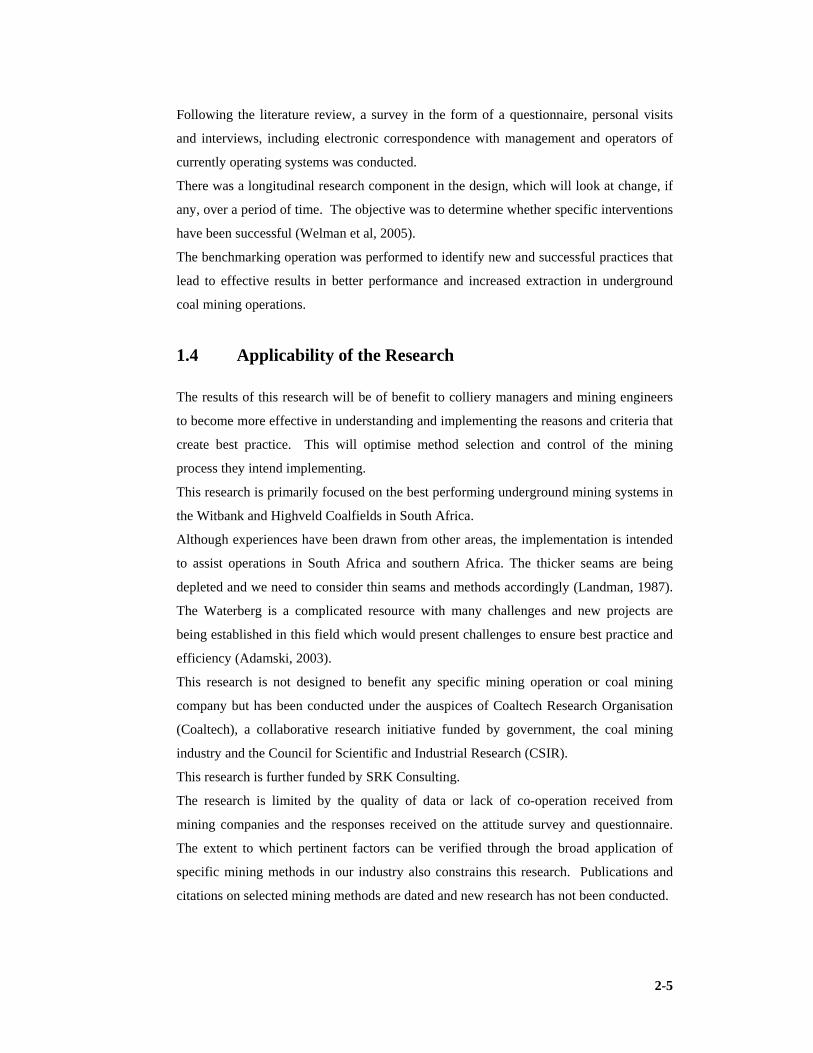
Following the literature review, a survey in the form of a questionnaire, personal visits
and interviews, including electronic correspondence with management and operators of
currently operating systems was conducted. The benchmarking operation was performed
to identify new and successful practices that lead to effective results in better performance
and increased extraction in underground coal mining operations.
5) To develop a structured guideline to mine design and operation best practice.
This is dealt with in the consideration of the mine planning and design process, the mine
life cycle and the role of the mining engineer in this life cycle. Twenty six (26) focus
areas have been identified and discussed in the penultimate Chapter.
The Study
This dissertation deals with a literature review and reports on major research conducted
that has influence and impacts this research. Valuable work has previously been
performed by Galvin (1981), Beukes (1992) and Lind (2004) amongst others.

v
The dissertation deals with the geology of appropriate current coalfields in South Africa
such as the Highveld, the Witbank and some analysis of the Waterberg field. The
Botswana and Zimbabwean fields are not overlooked.
Hydrogeology was dealt with to enhance understanding and the researcher looked
specifically at consequences in the high extraction environment. The material generated
was from a literature review. Here most of the learning is from work conducted by
Annandale (2006) and SRK Hydrology Group’s understanding of the science.
Rock engineering which has a major impact on design and performance of the preferred
high extraction best practice operations is considered from the perspectives of renowned
rock engineers and offers valuable insight for managers and operators. The material
generated was not original research during this project but sourced from literature. The
focus was on the secondary extraction environment. Most of the learning is from van der
Merwe and Madden (2002) and SRK Rock Engineering Group’s understanding of the
technology.
Choice of underground mining methods and factors that influence choice is not new in
the literature. Its application is still very current and purposeful. Owing to its relative
importance this has been reinforced. Applied techniques in this field, (as has been used in
a case study, by this researcher and found to be effective) have been included. Work by
Buchan et al (1981) is still very appropriate and has accordingly been reinforced in this
work. No design can be performed without systematically working through the elements
which have been grouped into broad economic, technological and geological classes.
A discussion follows, of thick seam and thin seam mining methods or mining profile if
they have been identified by managers as having best practice potential. Here innovative
technologies that assist in contributing to better performance are also examined.
Work performed by this researcher at Morupule Colliery during a prefeasibility and
feasibility stage was considered as a case study and identifies some of the issues design
engineers need to consider in the areas of hydrology, rock engineering and method
selection.
Chapters looked at certain best practice mining methods including international methods.
Here the focus is on technology and layout and to some extent the identification of key
performance indicators. One chapter deals with wall methods and the other with pillar
methods including partial extraction, pillar extraction and partial pillar extraction.
The research looked at the pertinent factors identified by the benchmarking exercise.
What characterises best practice and what gives certain operations ‘the edge’. It is in this
research document that the application of the soft issues is discussed. There is a trend of

vi
evidence that where the soft issues have been applied the production deliveries have
improved. Further data needs to be generated to prove the correlation. This research has
identified continuous improvement parameters and key performance indicators such as
QCDSM. The guidelines suggest the use of SOPs which have been identified by
management as good practice in the coal mining workplace and also suggest the
application of the Twenty Keys as adapted for mining. Other systems such as Six Sigma
developed by Motorola and applied to mining, have been considered. The better
performers have a system they apply. This research offers and has tested such a system. It
has applied soft systems thinking.
The Design Guideline deals with the Mine Planning and Design process and also refers to
the elements of an effective mine plan, it looks at mineral reporting codes and
competency. Appropriate Engineering Council of South Africa outcomes have been
identified.
Conclusions and Findings
In Chapter 14 conclusions and findings are drawn in the context of the objectives and
aims of this research as was developed for each chapter.
The aims and objectives of the research have been met. A guideline has been generated.
The report content has been successfully used to transfer knowledge to the B. Tech.
(Mining Engineering) candidates of the University of Johannesburg, Mining Department
during 2010 and will continue as course learning material to this target population.

vii
DEDICATION
To those students, who choose to enter our challenging profession, to mining men and
mining women everywhere, and those who teach them their skills………….
Stand proud!
The author wishes to express his sincere gratitude to the following persons for their help
in the preparation of this dissertation:
guidance, patience and valuable advice
man
for their financial support to enable me to conduct this research on a part time basis. Mr.
Beukes specifically, who has played a significant role in the early years of my
my mentor.
and understanding and friendship.
guidance and baseline data.
and encouragement.
collection of USA mines and his insights to some Australian ones.
for assistance with South African benchmark data.
Ernest Johnston
operations.
this research.
Heerden
at
their valued support.
trusting me as Project Manager during their Feasibility Study.
Colliery Manager’s Association, for assistance, in communication, with the mines, in
preparation for this research. My students
Johannesburg,
preliminary writing
van der Merwe
Landman
A special thank you
‘
Thank
ACKNOWLEDGEMENT
The author wishes to express his sincere gratitude to the following persons for their help
in the preparation of this dissertation:
guidance, patience and valuable advice
management team of Coaltech
for their financial support to enable me to conduct this research on a part time basis. Mr.
Beukes specifically, who has played a significant role in the early years of my
my mentor. Mr. Peter Knottenbelt
and understanding and friendship.
guidance and baseline data.
and encouragement.
collection of USA mines and his insights to some Australian ones.
for assistance with South African benchmark data.
Ernest Johnston
operations. The manage
this research.
Heerden and
at DRA Mineral Projects & DRA Mining,
their valued support.
trusting me as Project Manager during their Feasibility Study.
Colliery Manager’s Association, for assistance, in communication, with the mines, in
preparation for this research. My students
Johannesburg,
preliminary writing
van der Merwe
Landman and
A special thank you
‘SRK Consulting (Pty) Ltd.
Thank you!
ACKNOWLEDGEMENT
The author wishes to express his sincere gratitude to the following persons for their help
in the preparation of this dissertation:
guidance, patience and valuable advice
agement team of Coaltech
for their financial support to enable me to conduct this research on a part time basis. Mr.
Beukes specifically, who has played a significant role in the early years of my
Mr. Peter Knottenbelt
and understanding and friendship.
guidance and baseline data.
and encouragement. Mr. Freddy Hunter
collection of USA mines and his insights to some Australian ones.
for assistance with South African benchmark data.
Ernest Johnston, of Anglo Coal Australia, for data provided and advice on Australian
The managers
this research. My colleagues at SRK Consulting,
and Andy Mc D
DRA Mineral Projects & DRA Mining,
their valued support. Debswana, Morupule Colliery Limited, for data and
trusting me as Project Manager during their Feasibility Study.
Colliery Manager’s Association, for assistance, in communication, with the mines, in
preparation for this research. My students
Johannesburg, whom assisted me with fieldwork and entertained my discussions
preliminary writing. Acknowledgement and gratitude is further extended to
van der Merwe, Dr. Bernard Madden
and Dr. Rosemary Falcon
A special thank you in conclusion
SRK Consulting (Pty) Ltd.
!
ACKNOWLEDGEMENT
The author wishes to express his sincere gratitude to the following persons for their help
in the preparation of this dissertation:
guidance, patience and valuable advice
agement team of Coaltech Research Association a
for their financial support to enable me to conduct this research on a part time basis. Mr.
Beukes specifically, who has played a significant role in the early years of my
Mr. Peter Knottenbelt of the University of Johannesburg for his motivation
and understanding and friendship. Mr. Pierre Jordaan
guidance and baseline data. Mr. Neels Joubert
Mr. Freddy Hunter
collection of USA mines and his insights to some Australian ones.
for assistance with South African benchmark data.
, of Anglo Coal Australia, for data provided and advice on Australian
of the mines who participated, and whom so ably assisted with
My colleagues at SRK Consulting,
Donald for their
DRA Mineral Projects & DRA Mining,
Debswana, Morupule Colliery Limited, for data and
trusting me as Project Manager during their Feasibility Study.
Colliery Manager’s Association, for assistance, in communication, with the mines, in
preparation for this research. My students
whom assisted me with fieldwork and entertained my discussions
Acknowledgement and gratitude is further extended to
Dr. Bernard Madden
Dr. Rosemary Falcon for information provided.
in conclusion to
SRK Consulting (Pty) Ltd.’; and the
ACKNOWLEDGEMENT S
The author wishes to express his sincere gratitude to the following persons for their help
in the preparation of this dissertation: Professor Huw Phillips
guidance, patience and valuable advice offered
Research Association a
for their financial support to enable me to conduct this research on a part time basis. Mr.
Beukes specifically, who has played a significant role in the early years of my
of the University of Johannesburg for his motivation
Mr. Pierre Jordaan
Mr. Neels Joubert of Sasol Mining for sharin
Mr. Freddy Hunter of Sasol, Sigma Colliery, for assistance in data
collection of USA mines and his insights to some Australian ones.
for assistance with South African benchmark data. Messrs.
, of Anglo Coal Australia, for data provided and advice on Australian
of the mines who participated, and whom so ably assisted with
My colleagues at SRK Consulting,
their review work on this dissertation.
DRA Mineral Projects & DRA Mining, Mr. Dave Goosen
Debswana, Morupule Colliery Limited, for data and
trusting me as Project Manager during their Feasibility Study.
Colliery Manager’s Association, for assistance, in communication, with the mines, in
preparation for this research. My students and colle
whom assisted me with fieldwork and entertained my discussions
Acknowledgement and gratitude is further extended to
Dr. Bernard Madden, Dr. Con Fa
for information provided.
to ‘Coaltech’;
’; and the ‘University o
S
The author wishes to express his sincere gratitude to the following persons for their help
Professor Huw Phillips
offered. Mr. Johann Beukes
Research Association a collaborative research initiative
for their financial support to enable me to conduct this research on a part time basis. Mr.
Beukes specifically, who has played a significant role in the early years of my
of the University of Johannesburg for his motivation
Mr. Pierre Jordaan of Sasol, Secunda Collieries for
of Sasol Mining for sharin
of Sasol, Sigma Colliery, for assistance in data
collection of USA mines and his insights to some Australian ones.
Messrs. Ian Livingstone Blevins
, of Anglo Coal Australia, for data provided and advice on Australian
of the mines who participated, and whom so ably assisted with
My colleagues at SRK Consulting, Messrs. Andy
review work on this dissertation.
Dave Goosen and
Debswana, Morupule Colliery Limited, for data and
trusting me as Project Manager during their Feasibility Study.
Colliery Manager’s Association, for assistance, in communication, with the mines, in
and colleagues,
whom assisted me with fieldwork and entertained my discussions
Acknowledgement and gratitude is further extended to
Dr. Con Fauconier, Dr
for information provided.
’; ‘University of the Witwatersrand
of Johannesburg
The author wishes to express his sincere gratitude to the following persons for their help
Professor Huw Phillips for his supervision and
Mr. Johann Beukes
collaborative research initiative
for their financial support to enable me to conduct this research on a part time basis. Mr.
Beukes specifically, who has played a significant role in the early years of my
of the University of Johannesburg for his motivation
of Sasol, Secunda Collieries for
of Sasol Mining for sharing his insights
of Sasol, Sigma Colliery, for assistance in data
collection of USA mines and his insights to some Australian ones. Mr Hentie Hof
Livingstone Blevins
, of Anglo Coal Australia, for data provided and advice on Australian
of the mines who participated, and whom so ably assisted with
Andy Birtles,
review work on this dissertation. My colleagues
and Mr. Henk Prinsloo
Debswana, Morupule Colliery Limited, for data and field work and
trusting me as Project Manager during their Feasibility Study. The South African
Colliery Manager’s Association, for assistance, in communication, with the mines, in
, at the Univers
whom assisted me with fieldwork and entertained my discussions
Acknowledgement and gratitude is further extended to
Dr. Gavin Lind
University of the Witwatersrand
f Johannesburg’ for their support
The author wishes to express his sincere gratitude to the following persons for their help
for his supervision and
Mr. Johann Beukes and the
collaborative research initiative,
for their financial support to enable me to conduct this research on a part time basis. Mr.
Beukes specifically, who has played a significant role in the early years of my career, as
of the University of Johannesburg for his motivation
of Sasol, Secunda Collieries for
g his insights
of Sasol, Sigma Colliery, for assistance in data
Mr Hentie Hof fmann
Livingstone Blevins and
, of Anglo Coal Australia, for data provided and advice on Australian
of the mines who participated, and whom so ably assisted with
, Grant van
My colleagues
Henk Prinsloo for
field work and
The South African
Colliery Manager’s Association, for assistance, in communication, with the mines, in
at the University of
whom assisted me with fieldwork and entertained my discussions and
Acknowledgement and gratitude is further extended to Dr. Nielen
Gavin Lind , Dr. Gys
University of the Witwatersrand’;
for their support.

ix
CONTENTS
DECLARATION ii
ABSTRACT iii
Objectives iii
The Study iv
Conclusions and Findings vi
DEDICATION vii
ACKNOWLEDGEMENTS viii
CONTENTS ix
LIST OF FIGURES xxii
LIST OF TABLES xxx
LIST OF EQUATIONS xxxiii
NOMENCLATURE xxxiv
Presentation of Numbers and Units xxxiv
1 INTRODUCTION 2-1
1.1 Motivation for the Research 2-1
1.1.1 Problem statement 2-1
1.1.2 Justification 2-1
1.1.3 Resumé of the history of the problem 2-2
1.2 Objectives of the Research 2-4
1.3 Methodology of the Research 2-4

x
1.4 Applicability of the Research 2-5
1.5 Benchmarking Defined 2-6
1.6 Guideline Defined 2-7
1.7 Structure of the Research Dissertation 2-7
2 LITERATURE REVIEW 2-1
2.1 Previous Continuous Miner Best Practice Findings 2-1
2.2 Mining Thick Seams in South Africa 2-6
2.3 Guidelines for Pillar and Rib-Pillar Extraction 2-10
2.4 Increasing the Utilisation of Coal Resources through the Effective
Application of Technology 2-13
2.5 Thin Seam Mining 2-14
2.6 Geotechnical Factors Associated with the Choice of Mining
Method 2-16
2.7 Explosion Hazards 2-19
2.7.1 Disasters involving methane 2-21
2.8 New Methods and Techniques in Coal Winning 2-22
2.9 Coal Cutting Efficiency 2-25
2.10 Practical Mine Management 2-26
2.11 Systems Thinking 2-27
2.11.1 Value chain analysis 2-28
2.12 Quality Tools 2-29
2.12.1 Twenty Keys 2-30
2.12.2 Total Quality Management 2-31
2.12.3 Six Sigma 2-32
2.13 Conclusion 2-33
3 GEOLOGY 3-1
3.1 Coal and Coal Formation 3-1
3.1.1 Chronostratigraphy and lithostratigraphy 3-2
3.1.2 Macerals and lithotypes 3-6
3.2 Resources and Reserves 3-7
3.3 Coalfields in Southern Africa 3-10

xi
3.3.1 The significance of the Waterberg and Botswana coalfields 3-12
3.3.2 The importance of the Witbank and Highveld coalfields 3-15
3.4 The Significance of Pillar Coal 3-17
3.5 The Significance of Increased Extraction 3-17
3.6 The Potential of Discard Coal Products 3-18
3.7 Technical Challenges Presented by the Southern Hemisphere Coals 3-18
3.8 Conclusions 3-19
4 HYDROGEOLOGY 4-1
4.1 Hydrologic Cycle 4-1
4.2 Ground Water and Subsurface Water 4-1
4.2.1 Aquifers and confining beds 4-2
4.2.2 Ground water recharge and discharge 4-2
4.2.3 Ground water movement 4-3
4.2.4 Acid rock drainage 4-4
4.3 Definitions and Governing Equations 4-4
4.4 Groundwater in the South African Coalfields 4-4
4.4.1 Groundwater associated with dolerite dykes 4-5
4.4.2 Groundwater associated with dolerite sills 4-5
4.4.3 Groundwater associated with sandstones 4-5
4.4.4 Groundwater associated with shales 4-5
4.4.5 Groundwater associated with pre - Karoo rocks 4-6
4.5 Characteristics of the Highveld and Witbank Coalfield Aquifers 4-6
4.6 Effect of Increased Extraction on Groundwater 4-7
4.6.1 Rate of groundwater influx into areas of increased extraction 4-8
4.6.2 Rate of dewatering overlying and adjacent sediments 4-8
4.6.3 Chemical contamination of groundwater in areas of
increased extraction 4-9
4.6.4 Isolation of areas in which increased extraction has ceased 4-9
4.6.5 Recommendation for handling groundwater in areas of
increased extraction 4-10
4.7 Desalination of Pollute Groundwater 4-10
xii
4.8 Effects of Increased Underground Extraction on the Environment 4-10
4.8.1 Effect on the topography 4-10
4.8.2 Effect on surface runoff 4-11
4.8.3 Disposal of contaminated water 4-11
4.8.4 Effect of increased extraction on surface vegetation 4-11
4.9 A Case Study Illustrating the Importance of Ground Water in
Planning and Operating Coal Mines 4-11
4.9.1 Introduction and scope of the report 4-11
4.9.2 Background and brief 4-12
4.9.3 Geology, aquifers and confining layers 4-12
4.9.4 Piezometric levels and flow patterns 4-12
4.9.5 Groundwater use 4-13
4.9.6 Hydrochemistry 4-13
4.9.7 Potential groundwater inflows 4-13
4.9.8 Groundwater flow hazards 4-14
4.9.9 Acid rock drainage 4-15
4.9.10 Dewatering effects on water supply 4-15
4.9.11 Recommendations 4-15
4.10 Conclusions 4-19
5 ROCK ENGINEERING 5-1
5.1 Defining Rock Engineering 5-1
5.2 Friction Affects the Efficiency of Roof Support 5-1
5.3 Stratified Rock Layers Behave Like Beams 5-2
5.4 Underground Stress 5-3
5.4.1 Properties of some coal measure rocks 5-4
5.4.2 The stress effects of creating a roadway. 5-5
5.5 Geotechnical Classification 5-9
5.5.1 Rock mass classification 5-9
5.6 Roof and Sidewall Stability 5-10
5.6.1 Beam building as a strata control method 5-10
5.6.2 Suspension as a strata control method 5-11

xiii
5.6.3 Incorrect bolt installations 5-12
5.6.4 Breaker lines 5-14
5.7 Pillar Design 5-18
5.8 Rock Mechanics of Pillar Extraction 5-19
5.8.1 Critical panel width 5-20
5.8.2 Extraction safety factor (ESF) 5-20
5.8.3 Important points relative to pillar extraction 5-21
5.9 Rock Mechanics of Wall Mining 5-24
5.9.1 Stress history of a longwall panel 5-25
5.9.2 Inter-panel pillar design and longwall development 5-27
5.9.3 Secondary mining of inter-panel pillars 5-29
5.10 Causes of Falls of Roof in South African Collieries 5-31
5.11 A Case Study of Rock Engineering Principles used in a Coal Mine
Design 5-32
5.11.1 Structural environment 5-32
5.11.2 Geotechnical environment 5-34
5.11.3 Coal strength 5-36
5.11.4 Pillar loading 5-41
5.11.5 Mine design 5-41
5.11.6 Roof support and its optimisation 5-50
5.11.7 Inter-panel / barrier pillars 5-51
5.11.8 Underground dams 5-52
5.11.9 Risk assessment of the design 5-53
5.11.1 Opportunities for improved extraction 5-58
5.12 Conclusions 5-60
6 CHOICE CONSIDERATIONS 6-1
6.1 Introduction 6-1
6.2 Opencast versus Underground Mining. 6-1
6.3 Geological Parameters 6-2
6.4 Technological Parameters 6-3
6.5 Economic Parameters 6-3

xiv
6.6 Geometrical Factors 6-4
6.6.1 Thickness of overburden 6-4
6.6.2 Multiple seams 6-5
6.6.3 Seam thickness 6-6
6.7 Geological Factors 6-7
6.7.1 Primary geological structure 6-7
6.7.2 Secondary geological structure 6-8
6.7.3 Strata composition above the coal seam 6-9
6.7.4 In-seam partings 6-10
6.7.5 Vertical and lateral quality variations 6-10
6.7.6 Variations in seam thickness 6-11
6.7.7 Floor conditions 6-11
6.7.8 Water-bearing strata 6-11
6.8 Geotechnical Factors Associated with the Choice of Mining
Method 6-12
6.9 Explosion Hazards 6-12
6.10 Spontaneous Combustion 6-13
6.11 Surface Protection 6-13
6.12 Technology Factors 6-14
6.13 Economic Factors 6-15
6.13.1 Market considerations 6-15
6.13.2 Price of coal 6-15
6.13.3 Quality requirements 6-16
6.13.4 Size grading 6-16
6.13.5 Size of reserve 6-17
6.13.6 Capital 6-17
6.13.7 Labour 6-18
6.13.8 Availability of equipment 6-18
6.14 A Case Study Dealing with a Methodology Developed to Make a
Choice for a Pre-Feasibility Study 6-19
6.14.1 Introduction 6-19
6.14.2 Approach 6-20

xv
6.14.3 Mining methods considered 6-20
6.14.4 Decision criteria 6-20
6.14.5 Assessment 6-21
6.14.6 Results 6-21
6.15 Conclusions 6-24
7 CLASSIFICATION OF METHODS AND THE
IMPACT OF MINING HEIGHT 7-1
7.1 System of Classifying Mining Methods 7-1
7.1.1 Slicing 7-4
7.1.2 Caving and drawing 7-4
7.2 Major Underground Mining Systems 7-4
7.2.1 Roof supporting methods 7-6
7.2.2 Caving methods 7-7
7.2.3 Yielding pillar methods 7-10
7.2.4 Coal winning methods 7-11
7.3 Thick Seam Mining 7-14
7.3.1 Statistical background 7-14
7.3.2 Defining thick seams 7-15
7.3.3 Classification of South African thick seam coal reserves 7-15
7.3.4 The effect of past practices on the current situation 7-16
7.4 An Outline of Established Thick Seam Mining Methods 7-17
7.4.1 Bord and pillar mining 7-17
7.4.2 Longwall mining 7-18
7.5 Thin Seam Mining 7-24
7.5.1 Definition of thin seam mining 7-25
7.5.2 Classification of coal reserves 7-26
7.5.3 Equipment variation 7-26
7.5.4 Reserve utilisation 7-26
7.6 Thin Seam Mining Methods 7-26
7.6.1 Ram- plough mining with a pneumatic conveying system 7-27
7.6.2 Double stall low seam scraper mining 7-28

xvi
7.6.3 Fairchild Wilcox continuous miner 7-28
7.6.4 Low seam auger mining 7-29
7.6.5 The Collin’s miner 7-29
7.6.6 Full-face miners 7-31
7.6.7 Scraper box installations 7-31
7.6.8 Highwall mining 7-33
7.6.9 The Longwall Mining System 7-36
7.6.10 Modern systems as at 2008 7-38
7.7 Conclusion 7-44
8 WALL MINING METHODS 8-1
8.1 Introduction 8-1
8.2 Wall Mining 8-2
8.2.1 History 8-4
8.2.2 Advance wall mining 8-4
8.2.3 Retreat wall mining 8-5
8.2.4 Types of layout 8-7
8.2.5 Factors impacting on the design of wall layouts 8-7
8.2.6 Factors affecting the effectiveness of the longwall operation 8-26
8.2.7 Wall mining in the Witbank and Highveld coalfields in
South Africa 8-28
8.2.8 Longwall mining in China 8-34
8.2.9 Australian longwall productivity 8-36
8.3 Wall Mining Capital and Operating Costs for an Energy Project 8-47
8.4 Conclusion 8-49
9 PARTIAL EXTRACTION, PILLAR EXTRACTION
AND PARTIAL PILLAR EXTRACTION METHODS 9-1
9.1 Bord & Pillar Mining Using Continuous Miners 9-1
9.1.1 Overview of current mining operations in the Witbank and
Highveld coalfields 9-1
9.1.2 Application of full pillar extraction after 2004 9-11
9.1.3 Application of partial pillar extraction, after 2004. 9-13

xvii
9.1.4 New pillar extraction developments in South Africa. 9-14
9.1.5 Pillar extraction in Australia. 9-16
9.1.6 Partial extraction using continuous miners in primary
exploitation 9-22
9.1.7 Mining methods in the United States of America 9-35
9.2 Conclusion 9-42
10 INSTRUMENTS FOR MEASURING PERFORMANCE 10-1
10.1 Introduction 10-1
10.2 Reduction of Fine Coal Volumes 10-2
10.3 Coal Quality 10-5
10.4 Costs 10-7
10.4.1 Pithead cost 10-7
10.4.2 Maintenance cost 10-8
10.4.3 Labour cost 10-10
10.4.4 Operational cost 10-13
10.5 Delivery 10-14
10.6 Safety 10-18
10.7 Morale 10-19
10.8 Conclusion 10-20
11 CRITICAL ‘SOFT’ OBJECTIVES TO ENHANCE
PRODUCTIVITY 11-1
11.1 Get to the Working Place Quickly 11-1
11.2 Inspections Done Quickly 11-2
11.3 Leave Section in Good Condition at the End of a Shift 11-3
11.4 Reduce Cable Handling Time 11-3
11.5 Minimise Tramming and Manoeuvring 11-3
11.6 Maintain a Fast Cutting Cycle 11-3
11.7 Change Picks Quickly 11-4
11.8 Prevent Shuttle Car Cable Damages 11-4
11.9 Decrease Shuttle Car Change-Out Times 11-4
11.10 Support Roof Safely 11-5

xviii
11.11 Extend Infrastructure Every Two Pillars 11-5
11.12 Do as Much as Possible During the Off Shift 11-6
11.13 Apply Effective and Communicated Standard Operating
Procedures 11-6
11.14 Apply the Kobayashi 20 Keys 11-7
11.14.1 Cleaning and organising 11-8
11.14.2 Rationalising the system: Management by Objectives 11-8
11.14.3 Continuous improvement team activities 11-9
11.14.4 Reducing inventory and shortening lead time 11-9
11.14.5 Quick changeover technology 11-10
11.14.6 Manufacturing value analysis (methods improvement) 11-10
11.14.7 Zero monitor manufacturing / production 11-11
11.14.8 Coupled manufacturing / production 11-11
11.14.9 Maintaining machines and equipment 11-12
11.14.10 Time control and commitment 11-12
11.14.11 Quality assurance system 11-13
11.14.12 Developing suppliers 11-13
11.14.13 Eliminating waste (treasure map) 11-14
11.14.14 Empowering workers to make improvements 11-14
11.14.15 Skill, versatility and cross-training 11-15
11.14.16 Production scheduling 11-15
11.14.17 Efficiency control 11-15
11.14.18 Using information systems 11-16
11.14.19 Conserving energy and materials 11-17
11.14.20 Leading technology and site technology 11-17
11.15 Systems Thinking 11-18
11.15.1 Value chain analysis 11-18
11.16 Conclusion 11-19
12 BENCHMARK DATA 12-1
12.1 The 1Mtpa Production Target From One CM 12-3
12.1.1 Productivities Benchmarked 12-5

xix
12.1.2 Identifying the indicators from the benchmark results 12-6
12.1.3 Production international review 12-21
12.2 Conclusion 12-24
13 GUIDELINES TO COLLIERY DESIGN AND
OPERATION 13-1
13.1 Have a Competent Appreciation of Mine Planning and Design 13-1
13.1.1 Definition of mine planning and design 13-3
13.1.2 Integrated planning must be adopted 13-4
13.2 Secure Prospecting and Mining Rights 13-6
13.3 Proceed with Understanding the Role of the Mining Engineer in the
Mine Life Cycle 13-6
13.4 Accounting of Minutes in the Production Process and the 280
Minute Cutting Cycle Target. 13-8
13.5 Adopt a System of Best Practice SOP’s to Control Quality, Costs,
Delivery, Safety and Morale. 13-8
13.6 Apply an Effective Continuous Improvement Culture- the Twenty
Keys Strategy. 13-8
13.7 Implement a Realistic Appreciation of Production Delivery 13-9
13.8 Have a Competent Appreciation of Thick Seam Methods 13-10
13.9 Have a Competent Appreciation of Thin Seam Methods. 13-11
13.10 Have a Competent Appreciation of Mine Modelling Applications. 13-12
13.11 Understand what Charts and Data need to be Generated to
Delineate Pit Limits for the Design. 13-12
13.12 Understand the Coal Qualities Raw and Beneficiated and
Beneficiation Processes and Potential Product Qualities for the
Target Resource. 13-19
13.13 Have a Competent Appreciation of Previous Research 13-19
13.14 Consider Relevant Factors and be Systematic when Deciding on
the Implementation of Specific Mining Systems. 13-20
13.15 Maximise and Optimise Resource and Reserve Utilisation. 13-20

xx
13.16 Follow the Recognised Mineral Reporting Code and Guidelines to
Describe the Resources and Reserves to Achieve an Effective
Geological Model. 13-22
13.17 Ensure a Comprehensive Understanding of Hydrological Factors
that Impact the Target Area. 13-22
13.18 Ensure a Comprehensive Understanding of Geotechnical Factors
and Rock Engineering Criteria for the Design. 13-22
13.19 Ensure a Comprehensive Understanding of the Environmental
Impact and Develop an Effective Strategy for Environmental
Management. 13-23
13.19.1 VAM 13-23
13.20 Benchmark your Competitors and Other World Class Achievers. 13-24
13.21 Consult and Use the Leading Engineering and Science Consultancy
Professionals to Provide a Neutral and Impartially Independent
Perspective for the Design. 13-24
13.22 Elements of an Effective Design or Plan 13-24
13.23 When Leading a Project or Operation be a Great Leader 13-26
13.24 Understand and Use Competency Effectively 13-27
13.25 Develop a Suitable Risk Management Approach to Quantify the
Design and Operating Risks and Develop Mitigating Strategies to
Control the Risks. 13-32
13.26 Conclusion 13-35
14 CONCLUSIONS AND FINDINGS 14-1
14.1 Research Objectives 14-1
14.2 Geology 14-1
14.3 Hydrogeology 14-2
14.4 Rock Engineering 14-3
14.5 Choice of Method 14-3
14.6 Mining Height 14-4
14.6.1 Thick seam methods 14-5
14.6.2 Thin seam methods. 14-5

xxi
14.7 Wall Methods 14-6
14.8 Pillar Methods 14-6
14.9 Measuring Instruments (QCDSM) 14-7
14.10 Soft Issues (SOP’s and Kobayashi Twenty Keys) 14-7
14.11 Guideline for Effective Colliery Design and Operation 14-8
14.12 Benchmarking Results 14-8
14.13 Further Research 14-11
BIBLIOGRAPHY I
APPENDIX A: NOMENCLATURE IX
Index of Main Terms IX
General Glossary XII
Abbreviations XII
Units XIII

xxii
LIST OF FIGURES
Figure 2-1 Porter's Value Chain Model (from Jackson, 2004) 2-28
Figure 3-1 Gondwanaland during Carboniferous and early Permian (adapted
from Beukes, 1992) 3-2
Figure 3-2 International Stratigraphic Chart Quartenary to Carboniferous
System Period (After the International Commission on
Stratigraphy, a Geological Timescale, 2004) 3-4
Figure 3-3 International Stratigraphic Chart Devonian to Ecarchean System
Period (after ICS, 2004) 3-5
Figure 3-4 Resource and reserve classification (Mc Klevey Diagram, after US
Geological Survey) 3-7
Figure 3-5 Relationship between Exploration results, Mineral Resources and
Mineral Reserves (SAMREC Code, 2007) 3-9
Figure 3-6 Coalfields of South Africa (van Heerden, 2008) 3-13
Figure 3-7 Stratigraphy of the Morupule coalfield Botswana (van Heerden,
2008) 3-14
Figure 3-8 The Botswana Coalfields (van Heerden, 2008) 3-14
Figure 3-9 Highveld coalfield stratigraphy (after Lurie, 1976) 3-16
Figure 3-10 Statigraphy of the Witbank coalfield (after Lurie, 1976) 3-16
Figure 4-1 NW – SE Hydrological Cross-section Morupule Colliery (from
Dougall et al, 2009) 4-17
Figure 4-2 Water table contours and groundwater flow direction (from
Dougall et al, 2009) 4-18
Figure 5-1 A cantilever beam (from van der Merwe & Madden, 2002) 5-3
Figure 5-2 Showing redistribution of stresses when an excavation is created
(after van der Merwe & Madden, 2002) 5-5
Figure 5-3 Stress concentration in corners of roadway (from van der Merwe &
Madden, 2002) 5-6
Figure 5-4 Guttering due to horizontal stress (from van der Merwe & Madden,
2002) 5-7
Figure 5-5 Suspension of laminated beam (from van der Merwe & Madden,
2002) 5-11

xxiii
Figure 5-6 Visual error identification on roofbolt installations (from van der
Merwe & Madden, 2002) 5-13
Figure 5-7 Correctly installed bolts (from van der Merwe & Madden, 2002) 5-13
Figure 5-8 Mine pole breaker lines (from van der Merwe & Madden, 2002) 5-16
Figure 5-9 Roof bolt breaker lines (after van der Merwe & Madden, 2002) 5-17
Figure 5-10 Mobile breaker lines (after van der Merwe & Madden, 2002) 5-18
Figure 5-11 Stooping direction away from old goaf (Van der Merwe &
Madden, 2002) 5-21
Figure 5-12 Approximate safety factor of snooks during phases of pillar
extraction (Van der Merwe & Madden, 2002) 5-22
Figure 5-13 Ideal goaf position with only one line of snooks (Van der Merwe &
Madden, 2002) 5-22
Figure 5-14 Pillars should always be split at right angles to the goaf (Van der
Merwe & Madden, 2002) 5-23
Figure 5-15 Checkerboard stooping (Van der Merwe & Madden, 2002) 5-23
Figure 5-16 Pillar splitting orientation (Van der Merwe & Madden, 2002) 5-24
Figure 5-17 Stress transfer into abutments (after van der Merwe and Madden,
2002) 5-26
Figure 5-18 Overburden fails causing stress transfer through the goaf (after van
der Merwe and Madden, 2002) 5-26
Figure 5-19 Sketch of installation end of Longwall panel with longer inter-
panel pillars at start (after van der Merwe and Madden, 2002) 5-28
Figure 5-20 Yield pillar to control break (from van der Merwe and Madden
2002) 5-28
Figure 5-21 Complete extraction of 1 pillar & partial extraction of the other
(after van der Merwe and Madden, 2002) 5-30
Figure 5-22 Facebreak problem (from van der Merwe and Madden, 2002) 5-31
Figure 5-23 Illustration of the variation in pillar loading (Depth to Span Ratios)
from Dougall et al (2009) 5-46
Figure 5-24 Illustration of the variation in pillar loading (panel widths) (from
Dougall et al (2009) courtesy SRK Consulting). 5-47
Figure 5-25 Hydraulic design chart for a coal bounded barrier pillar (from
Dougall et al, 2009) 5-52
Figure 5-26 Event-consequence tree for a pillar system designed at safety factor
1.8 (from Dougall et al, 2009) 5-56

xxiv
Figure 5-27 Event-consequence tree for a pillar system designed with bottom
coaling at safety factor 1.4 (from Dougall et al, 2009). 5-57
Figure 5-28 United Kingdom Health and Safety Executive Guidelines on Risk
Acceptance (based on Salamon and Hartford, 1995) 5-57
Figure 6-1 Approach to method selection (after Prinsloo, 2008) 6-21
Figure 7-1 Classification of underground mining methods (after Galvin 1981) 7-2
Figure 7-2 Reduced extraction rate with increased depth when using pillars
(after Fauconier, 1982) 7-11
Figure 7-3 Typical Bord & Pillar layout (from the Chamber of Mines
Handbook for Colliery Ventilation) 7-18
Figure 7-4 Extended height single pass longwall operation (courtesy West
Wallsand Colliery) 7-18
Figure 7-5 Multi-slice longwall with sand backfill (after Myszkowski, 2004) 7-20
Figure 7-6 Multi-slice longwall with roof fall (after Myszkowski, 2004) 7-21
Figure 7-7 Multi-slice longwall with artificial roof (after Myszkowski, 2004) 7-21
Figure 7-8 Multi-slice longwall with goaf cavity filling (after Myszkowski,
2004) 7-22
Figure 7-9 Multi-slice longwall with backfill and roof fall (after Myszkowski,
2004) 7-22
Figure 7-10 Top coaling with single AFC (after Myszkowski, 2004) 7-24
Figure 7-11 Top coaling with double AFC (after Myszkowski, 2004) 7-24
Figure 7-12 Ram Plough system (after Holman et al, 1999) 7-27
Figure 7-13 Fairchild Wilcox system (after Holman et al, 1999) 7-28
Figure 7-14 Collin’s miner system plan view (after Landsdown, 1963) 7-29
Figure 7-15 Collin’s miner section view (after Landsdown, 1963) 7-30
Figure 7-16 In-seam miner (after Landsdown, 1963) 7-31
Figure 7-17 Chain tension scraper layout (after Landsdown, 1963) 7-32
Figure 7-18 Layout of highwall mining operations (after Treuhaft, 1981) 7-33
Figure 7-19 The Addcar Highwall system (after Treuhaft, 1981) 7-35
Figure 7-20 The Longwall coal plough system (after Landsdown, 1963) 7-37
Figure 7-21 Face layout for the Underground Auger mining layout (from
Holman, 1999) 7-39
Figure 7-22 JOY 14 CM cutting system with a 750mm cutting drum (after
joy.com, 2006) 7-40
Figure 7-23 Continuous miner and backfilling operation (after joy.com, 2006) 7-41

xxv
Figure 7-24 The Continuous Miner and the conveyor train (after joy.com,
2006) 7-41
Figure 7-25 Mining and ventilation layout for a Continuous Miner section
(after joy.com, 2006) 7-42
Figure 7-26 Fairchild Dual Auger continuous miner (from
fairchildtechnologies.com, 2006) 7-43
Figure 7-27 Dual Head Auger operation and stull ventilation (from
airchildtechnologies.com, 2006) 7-44
Figure 8-1 Orthographic view of longwall panel (from Joy) 8-3
Figure 8-2 Advance longwall mining (After Fauconier 1982) 8-5
Figure 8-3 Retreat longwall mining (After Fauconier 1982) 8-6
Figure 8-4 Ventilation flow top seam longwall (DNC) (After Fauconier 1982 8-15
Figure 8-5 General arrangement of ventilation (Coalbrooke) (Fauconier &
Kersten, 1982) 8-16
Figure 8-6 Shearer cutting return run half facing 8-19
Figure 8-7 Shearer prior to sump in cycle 8-20
Figure 8-8 AFC dual flight chain (Joy Industries) 8-21
Figure 8-9 AFC and chock push over (DNC) (After Fauconier, 1982) 8-21
Figure 8-10 In-line breaker 8-22
Figure 8-11 Long - Airdox stageloader (After Long Airdox website) 8-23
Figure 8-12 Section of a chock shield 8-23
Figure 8-13 Shield supports (courtesy Matla) 8-24
Figure 8-14 Remote power house 8-25
Figure 8-15 Pantechnikon applied on Matla (from Matla) 8-25
Figure 8-16 Matla stratigraphy (from Matla) 8-30
Figure 8-17 Determination of optimum face length (Matla Presentation, Nel J,
2006) 8-30
Figure 8-18 Matla panel layout (Matla Presentation, Nel J, 2006) 8-31
Figure 8-19 Matla wall face (Matla Presentation, Nel J, 2006) 8-32
Figure 8-20 DBT shields (Matla Presentation, Nel J, 2006) 8-32
Figure 8-21 Joy shearer (Matla Presentation, Nel J, 2006) 8-33
Figure 8-22 Production results for various panels (Matla Presentation, Nel J,
2006) 8-33
Figure 8-23 Chinese localities (from Coaltech) 8-35
Figure 8-24 Aquila highwall entry (Capcoal Presentation, Johnson E, 2009) 8-45

xxvi
Figure 8-25 Capcoal German Creek Operations (Johnson, 2008) 8-46
Figure 9-1 Pillar extraction sequence Twistdraai Colliery (after Lind, 2004) 9-3
Figure 9-2 Nevid layout at Secunda (after Lind, 2004) 9-5
Figure 9-3 Pillar extraction layout, Arthur Taylor (after Lind, 2004) 9-6
Figure 9-4 Extraction sequence at Boschmans Colliery (after Lind, 2004) 9-8
Figure 9-5 Pillar lifting sequence Gloria Colliery (after Lind, 2004) 9-9
Figure 9-6 Extraction cycle (after van der Merwe, 2001) 9-15
Figure 9-7 Proposed high extraction panel layout (after van der Merwe, 2001) 9-15
Figure 9-8 Mobile breaker line deployment (after Lind, 2004) 9-18
Figure 9-9 Pillar extraction Bellambi West Colliery (after Lind, 2004) 9-18
Figure 9-10 Panel layout Charbon colliery (modified Wongawilli split & lift)
(after Lind, 2004) 9-22
Figure 9-11 New South Wales coalfields (after Lind, 2004) 9-24
Figure 9-12 Long-Airdox Continuous Haulage (Uys, Syferfontein presentation,
2006) 9-25
Figure 9-13 ABM 30 wide head continuous miner (Uys, Syferfontein
presentation, 2006) 9-25
Figure 9-14 ABM 30 Elevated head (Uys, Syferfontein presentation, 2006) 9-26
Figure 9-15 Section layout with diagonal pillars (Uys, Syferfontein
presentation, 2006) 9-26
Figure 9-16 Peak production with ABM 30 & Continuous Haulage (Uys,
Syferfontein presentation, 2006) 9-27
Figure 9-17 Magatar comparative statistics in 1.8m seam height (Venter,
Personal communication, 2009) 9-28
Figure 9-18 Magatar development and panel layout (Venter, Personal
communication, 2009) 9-28
Figure 9-19 ELBM-75 Vibrant roadheader (after Coaltech) 9-29
Figure 9-20 Rear view of Vibrant roadheader (after Coaltech) 9-31
Figure 9-21 The ARO Twin boom bolter (Kenny, Douglas presentation, 2008) 9-32
Figure 9-22 Roofbolts installed per day using ARO (after Kenny, Douglas
presentation, 2008) 9-32
Figure 9-23 A continuous miner buried in the goaf with rock bolts that could
not suspend the load (Elliot, Fletcher Presentation , 2006) 9-34
Figure 9-24 The 16m productive option but code generally requires 12m for
enhanced safety(Elliot, Fletcher Presentation , 2006) 9-34
xxvii
Figure 9-25 Fletcher bolter (Elliot, Fletcher Presentation , 2006) 9-35
Figure 9-26 Black Beauty Air Quality # 1 Mine (After Hunter, 2007) 9-36
Figure 9-27 Black Beauty Francisco Mine (after Hunter, 2007) 9-37
Figure 9-28 Prosperity Mine (after Hunter, 2007) 9-38
Figure 9-29 Freelandville Mine (after Hunter, 2007) 9-38
Figure 9-30 Adit approach in hilly region for Speed Mine (after Hunter, 2007) 9-39
Figure 9-31 Forklift (photo by Hunter) 9-40
Figure 9-32 Grader (photo by Hunter) 9-40
Figure 9-33 Getman Scoop for service use (photo by Hunter) 9-41
Figure 9-34 Low bed trailer (photo by Hunter) 9-42
Figure 10-1 Projected pithead cash costs for 2010 from 2004 data 10-8
Figure 10-2 Labour complement per shift 10-11
Figure 10-3 Shifts per week 10-12
Figure 10-4 Machine overhauls 10-14
Figure 10-5 Monthly Production 10-16
Figure 10-6 Production per shift 10-16
Figure 10-7 Pick efficiencies 10-18
Figure 11-1 Michael Porter’s Value Chain System (after Jackson, 2004) 11-19
Figure12-1 Magatar layout with CM and CH in chain road (after Venter, 2009) 12-2
Figure 12-2 South African CM operations that have 1Mtpa potential (2009 Jan
to Sep) (from Anglo Coal) 12-4
Figure 12-3 Production from Mine 1 (1); Mine 2 (2); 55 Eskom Collieries 1999
Avg. (3); 55 Eskom Collieries 2001 Avg. (4) 12-6
Figure 12-4 Mining conditions per section 12-10
Figure 12-5 Industry Benchmark tonnes per month (data from Hoffman &
MCS) 12-11
Figure 12-6 Industry Benchmark tonnes per week (data from Hoffman & MCS) 12-12
Figure 12-7 Shifts per week for the IBP performers (data from Hoffman &
MCS) 12-12
Figure 12-8 Benchmark production tonnes per shift (data from Hoffman &
MCS) 12-13
Figure 12-9 IBP for machine available hours (data from Hoffman & MCS) 12-14
Figure 12-10 IBP for tonnes per machine available hour (data from Hoffman &
MCS) 12-14
Figure 12-11 IBP for cutting rate (data from Hoffman & MCS) 12-15

xxviii
Figure 12-12 IBP Away Time (data from Hoffman & MCS) 12-16
Figure 12-13 IBP for average time per relocation (data from Hoffman & MCS) 12-17
Figure 12-14 IBP for Relocation Efficiency (Tram to wait ratio) (from MCS) 12-18
Figure 12-15 IBP for CM Downtime as percentage of shift (data from Hoffman
& MCS) 12-18
Figure 12-16 IBP for SC/BH Downtime (percentage of shift) (data from
Hoffman & MCS) 12-19
Figure 12-17 IBP Conveyor Downtime (percentage of shift) (data from Hoffman
& MCS) 12-19
Figure 12-18 Other Downtime (percentage of shift time) (data from Hoffman &
MCS) 12-20
Figure 12-19 IBP for Total Travel Time (data from Hoffman & MCS) 12-21
Figure 12-20 Benchmarking USA tonnes per annum (data from Hoffman &
MCS) 12-22
Figure 12-21 Benchmarking USA tonnes per shift (data from Hoffman & MCS) 12-22
Figure 13-1 Competent person and reporting standard 13-3
Figure 13-2 Integrated Mine Planning 13-5
Figure 13-3 Planning and design process (from Fourie & van Niekerk, 2001) 13-7
Figure 13-4 Thin seam CM 13-12
Figure 13-5 Plan floor elevation (mamsl) contours and palaeo-valley axis (from
Dougall et al, 2009) 13-13
Figure 13-6 Plan showing thickness contours (from Dougall et al, 2009) 13-13
Figure 13-7 Plan Showing In-situ calorific value (air-dried uncontaminated) ad.
uc. contours (from Dougall et al, 2009) 13-14
Figure 13-8 Plan showing In Situ Ash Content contours (Full seam thickness)
(from Dougall et al, 2009) 13-14
Figure 13-9 Plan showing In Situ Volatile Content contours (Full seam
thickness) (from Dougall et al, 2009) 13-15
Figure 13-10 Plan showing the aeromagnetic image and the preliminary
interpretation (from Dougall et al, 2009) 13-15
Figure 13-11 JORC Classification of Measured, Indicated and Inferred Coal
Resources (from Dougall et al, 2009) 13-17
Figure 13-12 Exploration boreholes (from Dougall et al, 2009) 13-17
Figure 13-13 Feasibility Study Mine Layout (from Dougall et al, 2009) 13-18
Figure 13-14 RoM coal 3.6Mtpa Qualities ad. uc. (from Dougall et al, 2009) 13-19

xxix
Figure 13-15 Mining sequence (from Dougall et al, 2009) 13-21
Figure 13-16 Individual CM mining areas and schedule (from Dougall et al,
2009) 13-21
Figure 13-17 Relationships between Exploration Results, Mineral Resources and
Ore Reserves (from the Samrec Code, 2007) 13-22
Figure 13-18 Competent persons model (from MQA) 13-28
Figure 13-19 Practicing person model (from MQA) 13-28
Figure 13-20 Two stage developmental model (from MQA) 13-30
Figure 13-21 Major Groups of OFO broadly mapped against NQF levels (from
MQA) 13-31
Figure 13-22 Methane explosion generated at Klopperbos Research Facility 13-32
Figure 13-23 Minerals Industry Risk Management Process (from Anglo A3 RM
Course) 13-33
Figure 13-24 Integrated Risk Management Risk Matrix 13-34
Figure 14-1 Summary of IBP relative to GBP (from MCS Xstrata Report) 14-10

xxx
LIST OF TABLES
Table 0-1 Units and format used xxxiv
Table 2-1 Classification of thick seam mining methods 2-8
Table 2-2 Factors with major impact (after Jeffery, 2002) 2-17
Table 2-3 Factors with minor impact (after Jeffery, 2002) 2-17
Table 2-4 Factors with moderate impact (after Jeffery, 2002) 2-18
Table 3-1 Chronostratigraphy and Lithostratigraphy (after Beukes, 1992) 3-3
Table 3-2 Comparison of hemisphere coals (after Macgregor, 1983) 3-6
Table 3-3 Resource and reserve category (after SAMREC, 2007) 3-8
Table 3-4 Estimates of SA Coal Reserves (Jeffery, 2005) 3-9
Table 3-5 Coal zones in the Waterberg as exposed at Grootegeluk (Adamski,
2003) 3-12
Table 5-1 Mechanical properties of some rocks found in coal measures (after
van der Merwe & Madden. 2002) 5-5
Table 5-2 Support element characteristics (from Van der Merwe & Madden,
2002) 5-14
Table 5-3 Rock mass properties for Morupule 5-35
Table 5-4 Rock properties used in the ATS assessment 5-35
Table 5-5 Rock and soil properties derived from laboratory testing 5-35
Table 5-6 Summary of Pillar Strength formulae 5-36
Table 5-7 Depth to span ratios for 7 roadway production panels 5-42
Table 5-8 Design parameters used in the pre-feasibility study 5-45
Table 5-9 Design Parameters for Primary Main Development including a
Squat Pillar adjustment. 5-48
Table 5-10 Design parameters for Primary Main Development. 5-48
Table 5-11 Design Parameters for Production Panels including a Squat Pillar
adjustment. 5-49
Table 5-12 Design parameters for Production Panels, Safety Factor 1.8 5-49
Table 5-13 Likelihood descriptions 5-53
Table 5-14 Generalised baseline geotechnical risk assessment 5-55
Table 5-15 Summary of probabilities for different monitoring and evacuation
system effectiveness. 5-56
Table 5-16 Design parameters for maximisation of the cut height. 5-59

xxxi
Table 5-17 Design parameters for standard bottom coaling, safety factor 1.8 5-60
Table 6-1 Decision criteria used during the evaluation (after Prinsloo, 2008). 6-22
Table 6-2 Scoring criteria (after Prinsloo, 2008) 6-23
Table 6-3 Methods eliminated (after Prinsloo, 2008) 6-23
Table 6-4 Selection matrix (after Prinsloo, 2008) 6-24
Table 7-1 Classification of thick seam mining (after Galvin, 1981) 7-3
Table 8-1 Extraction rates (After Fauconier, 1982) 8-12
Table 8-2 Production at Shendong Mine Complex. (Shendong presentation,
Coaltech, 2004) 8-36
Table 8-3 Mining Method Mix NSW (Macdonald 2008). 8-38
Table 8-4 Summary of coal statistics for NSW (Macdonald, 2008) 8-38
Table 8-5 Australian Production Statistics (After Australian Longwall
Magazine) 8-39
Table 8-6: Mining Capital Costs (from Macdonald, 2010) 8-48
Table 8-7: Mining Operating Costs (from Macdonald, 2010) 8-48
Table 8-8: Processing Capital Costs (from Macdonald, 2010) 8-48
Table 8-9: Processing Operating Costs (from Macdonald, 2010) 8-49
Table 9-1 Complement per shift (after Lind, 2004) 9-17
Table 9-2 History of rib-pillar and pillar extraction developments in Australia
(Sheppard & Chaturverdula, 1991) 9-20
Table 9-3 Labour complement per shift 9-22
Table 9-4 Labour complement per day 9-27
Table 9-5 Rock bolt costs (2009) (Franklin, Minova) 9-33
Table 9-6 Cost of resin (2009) (Franklin, Minova) 9-33
Table 10-1 Mines with fine coal as threat and actions to counteract it (from
Scheepers et al 2000) 10-4
Table 10-2 Quality control at mines (from Scheepers et al 2000) 10-6
Table 10-3 Maintenance cost drivers 10-9
Table 10-4 Section labour on a shift basis (From Scheepers et al (2000) 10-12
Table 10-5 Pick and roofbolt efficiencies (from Scheepers et al, 2000) 10-13
Table 10-6 Production levels from Scheepers et al (2000) 10-17
Table 11-1 Transport options of better producing mines (from Scheepers et al,
2000) 11-2
Table 11-2 Belt extension data (from Scheepers et al (2000) 11-5
Table 11-3 Off-shift activity (from Scheepers et al, 2000) 11-6

xxxii
Table 12-1 Group Best Practice (GBP) across a range of key functions (From
MCS Report, 2006) 12-8
Table 12-2 GBP potential production for each colliery (MCS Report, 2006) 12-8
Table 12-3 Shift systems 12-9
Table 12-4 Away time (from MCS) 12-16
Table 12-5 IBP and GBP Summary (from MCS) 12-23
Table 13-1 Planning levels and outcomes 13-4
Table 13-2 Classified Coal Resource Estimates at 4.2m mining height within
the Project Area (RD 1.51) (from Dougall et al, 2009) 13-16
Table 13-3 In Situ Coal Qualities (Full Seam Thickness) (Project Area) (Grid
Info) (from Dougall et al, 2009) 13-16
Table 13-4 Conversion of In Situ Coal Resources to RoM Coal Reserves
(4.2m) (from Dougall et al, 2009) 13-18

xxxiii
LIST OF EQUATIONS
Equation 4-1 The Thiem Equation for steady state seepage 4-14
Equation 5-1 Coulomb Equation 5-1
Equation 5-2 Magnitude of the maximum tensile stress 5-2
Equation 5-3 Critical mining span incompetent strata 5-20
Equation 5-4 Critical mining span strong strata 5-20
Equation 5-5 Induced Strain 5-38
Equation 5-6 Rock Mass Strength 5-39
Equation 5-7 Pillar Strength 5-42
Equation 5-8 Squat Pillar Strength 5-42
Equation 5-9 Pillar Load 5-43
Equation 5-10 Safety Factor 5-43
Equation 5-11 Areal Extraction 5-43
Equation 5-12 Volumetric Extraction 5-43
Equation 7-1 Stable Pillar layout as a function of stiffness of layout 7-10
Equation 8-1 Optimising wall face length 8-26

xxxiv
NOMENCLATURE
The full list of nomenclature has been included as an appendix and includes:
1) Glossary
Specific Index of main terms in this report
2) Abbreviations
3) Units
Presentation of Numbers and Units
In this dissertation the researcher has adopted the commonly used presentation format for
numbers and units. These are summarised in Table 0.1.
Table 0-1 Units and format used
Unit Format Comment
Thousands 123,456 One hundred and twenty three thousand and for hundred and
fifty six.
Decimals 12.345 Twelve point three four five
Use decimal point not comma.
Degrees 12º15'30.12" Twelve degrees fifteen minutes and thirty point one two
seconds
Coal
resources
decimal
places
12.345Mt Number of decimal places depends on classification no more
than three.
Coal qualities
decimal
places
12.34% or
12.34MJ/kg
Generally no more to two decimal places except for
Phosphorus which should require 3 decimal places 0.001%

2-1
1 INTRODUCTION
1.1 Motivation for the Research
There are many factors that impact on a coal producing operation. Identifying the most
effective and efficient production systems and then analysing these to determine the
factors contributing to the results is paramount to the understanding, management and
planning of future operations. This in turn will contribute to optimisation of resource
utilisation and the economic extraction of the reserves.
1.1.1 Problem statement
The purpose of the study is highlighted by the following problem statement: There is a
need to increase current productivity levels in underground coal mining in South Africa
and guidelines for achieving this need to be developed.
1.1.2 Justification
It has been reported that in South Africa the coal mining industry is a major component of
the overall economy. The Industry accounts for 1.5% of gross domestic product (GDP,
the value of products and services produced within the geographic borders of a state) and
is the primary energy source for approximately 90% of electricity production. It is vital
therefore that it should continue to make its contribution to the development of the
country, both as a local source of relatively cheap electricity and the earning of foreign
exchange for the country (Lind, 2004).
A concern is that at current levels of extraction, from existing coalfields, the coal mining
industry in South Africa has a life expectancy of 25 years (Lind & Phillips, 2001). This
researcher considers this life expectancy to be very conservative as projects currently
being established are planned to exceed this. However, this is disturbing when we
consider southern Africa’s dependence on coal-derived energy. The endeavour to
maximise the effectiveness of the resource utilisation is critical to the sustainability of
first world life-styles to which South Africa aspires.
Improvement in productivity and better resource utilisation as a consequence of this
research effort, would derive a cost benefit difficult to quantify precisely, but is expected

2-2
to be of the order of millions of Rand. It should also be noted that this optimising of
production levels and enabling the delivery of product to required targets will eliminate
wastage or excessive downtime. Achieving a higher percentage extraction owing to
secondary or high extraction processes and methods will realise these financial gains. For
every extra 100,000t obtained from a resource, additional revenue of the order of ZAR12,
000,000 can be derived. This was estimated at a 2009 price of ZAR120 per tonne for
domestic power station feed. The life extension of infrastructure will contribute to
significant saving. The costs and wastage of re-establishment of the Witbank
infrastructure in the Waterberg Coalfield is another factor in determining this impact.
1.1.3 Resumé of the history of the problem
Various researchers have previously focused on aspects of mechanised underground coal
mining as a contributing factor for productivity increases and these studies had the
objective of enhancing the understanding of the required process.
In constructive work by Beukes (1992) he dealt with pertinent facts to promote the
performance of underground mining systems and generated design guidelines for pillar
extraction (Beukes, 1992).
Research by Galvin (1981) of the Chamber of Mines Research Organisation (COMRO)
aimed to provide a foundation on which to base decisions concerning the implementation
of efficient underground mining methods for thick coal seams in South Africa (Galvin,
1981). For the purpose of this work, a thick seam was defined as any seam more than 4m
thick. However, a number of multi-seam situations where the parting between seams is
less than 2m thick and the seams are each at least 2m thick have also been included in this
definition.
Thick seam mining methods, which have become established in countries throughout the
world, are identified in Galvin’s research. They are classified in terms of two criteria,
namely the extracted seam height and roof strata behaviour, which take the form of a
matrix. The geological and economic characteristics and requirements of each of the
methods have been evaluated and tabulated with local geological and economic
conditions for later comparison.
Research by Lind (2004) developed a significant design tool to enable better resource
utilisation. In this thesis, the development of a design tool which would aid decision
makers in assessing their potential to conduct underground coal pillar extraction had its
foundations in the main objective of increasing the utilisation of coal resources in the

2-3
Witbank and Highveld coalfields of South Africa. The report initially reviewed the
evolution of underground coal pillar extraction in South Africa and tracked international
advances in this technique. Developments of planning methodologies as well as an
analysis of safety issues pertaining to this mining method were discussed.
In focused work by Jeffrey (2002), the researcher identified the geotechnical factors that
impact upon the choice of mining method. Recent research suggests that most Witbank
coalfield collieries will close during the 2020’s unless the remaining pillar coal is
exploited. Successful re-mining of these pillars will heavily depend on understanding the
roles geotechnical factors play in the developing strategies to ameliorate their effects
(Jeffery, 2002). She also noted that, the selection of a secondary extraction method is
therefore most strongly affected by stratigraphy and the primary mining parameters.
Jeffery ranked and identified the factors, which impact on underground secondary
extraction, in major, moderate and minor categories.
A United States publication discussed middle and front line management in collieries.
The work (Britton, 1981) focused on the duties, responsibilities and efforts of supervisors
in both underground and surface mining. It also analyses the management problems with
costs, workers, safety, productivity, training and technical staff and presented some
practical ideas for improving them.
It can be seen that all the work referred to above has focused on increasing the
effectiveness of the selection process but this researcher believes that behavioural or “soft
issues” are not adequately identified in the previous work and action is needed to
determine what makes the better systems more effective. Soft Systems (Soft Issues) are
derived from Jackson’s Model of Systems Thinking (Oberholzer, 1986). Jackson
authored the concept of Hard Systems Thinking in which a system is defined as “a
complex whole, the functioning of which depends on its parts and the interactions
between those parts” (Jackson, 1985). It may well be that the “soft issues”, namely “the
workforce’s attitude with regard to issues such as cycle times, getting to the working
place on time, shift change-over, housekeeping, amongst others, are the critical factors
that make some systems perform better than others. This research will attempt to
understand what the best combinations of layout and method selection are and the
standards required which will include consideration of the soft issues to enable mining
operations to develop benchmark world class performance” (Dougall, 2009).
Chapter 2 of this research deals with a more extensive review of available and relevant
literature.

2-4
1.2 Objectives of the Research
A need exists to increase productivity levels of underground mining operations. This
research will identify the factors which influence the performance of these operations,
through an international benchmarking study.
The study is aimed at identifying colliery specific indicators which, when compared
against group and industry specific best practice standards, would highlight areas of
potential improvement and would provide a valuable resource for managing and adding
value to operations.
The objectives of the research are:
1) To study underground exploitation methods in South African coal mines considering
the application and utilisation of certain equipment. This includes identifying recent
local (Africa) and international (USA, China and Australia) best practice information
as recent top performances have been reported from these countries.
2) To identify pertinent success factors and provide guidelines to management and
operators to ensure productivity and effective reserve utilisation.
3) To identify factors that influences the choice of underground mining methods.
4) To identify factors relating to equipment selection.
Issues that mining engineers have to consider when designing systems will be identified
and also recommend what operators have to do to attain world class performance. The
research will endeavour to answer the question “what do best performers use and do to
attain world class performance and best practice?” This will be tested against what
manager’s consider being best practice and world class performance.
1.3 Methodology of the Research
The procedures presented in this research took the form of a comprehensive literature
survey of both local and international experiences pertaining to underground coal mining.
The focus being on seam thickness i.e., thick seam, medium seam and thin seam (low
seam) profiles and increasing the extraction processes. This was conducted to assess the
basis on whether or not these practices have factors or behaviours that lead to effective
productivity levels and effective resource utilisation.
2-5
Following the literature review, a survey in the form of a questionnaire, personal visits
and interviews, including electronic correspondence with management and operators of
currently operating systems was conducted.
There was a longitudinal research component in the design, which will look at change, if
any, over a period of time. The objective was to determine whether specific interventions
have been successful (Welman et al, 2005).
The benchmarking operation was performed to identify new and successful practices that
lead to effective results in better performance and increased extraction in underground
coal mining operations.
1.4 Applicability of the Research
The results of this research will be of benefit to colliery managers and mining engineers
to become more effective in understanding and implementing the reasons and criteria that
create best practice. This will optimise method selection and control of the mining
process they intend implementing.
This research is primarily focused on the best performing underground mining systems in
the Witbank and Highveld Coalfields in South Africa.
Although experiences have been drawn from other areas, the implementation is intended
to assist operations in South Africa and southern Africa. The thicker seams are being
depleted and we need to consider thin seams and methods accordingly (Landman, 1987).
The Waterberg is a complicated resource with many challenges and new projects are
being established in this field which would present challenges to ensure best practice and
efficiency (Adamski, 2003).
This research is not designed to benefit any specific mining operation or coal mining
company but has been conducted under the auspices of Coaltech Research Organisation
(Coaltech), a collaborative research initiative funded by government, the coal mining
industry and the Council for Scientific and Industrial Research (CSIR).
This research is further funded by SRK Consulting.
The research is limited by the quality of data or lack of co-operation received from
mining companies and the responses received on the attitude survey and questionnaire.
The extent to which pertinent factors can be verified through the broad application of
specific mining methods in our industry also constrains this research. Publications and
citations on selected mining methods are dated and new research has not been conducted.

2-6
The research is intended to be descriptive, which means “A specific situation is studied to
see if it will give rise to any general theories or see if any existing theories are borne out
by the specific situation” (Welman et al, 2005).
It is also assumed that the readers of this dissertation are familiar with underground coal
mining practice and processes.
1.5 Benchmarking Defined
It would be appropriate to look at some definition of Benchmarking at this stage and one
authority refers to Benchmarking as, “An externally focused, performance improvement
method, for continuously and systematically comparing the performances and practices of
business operations, to the best in class, in any industry. This process is used to develop
operational plans to surpass the current best in class performance. It can take the form of
Internal -, External -, Functional – and Generic Benchmarking” (Cronje et al, 2003).
Benchmarking has been further defined by Scheepers as “Benchmarking is the continuous
process of measuring our products, services and practices against our toughest competitor
or those companies recognised as industry leaders. A surveyors mark of previously
determined position and used as a reference point, a standard, by which something can be
measured or judged” (Scheepers et al, 2000).
A consultant’s report elaborates on Internal, Competitive and Functional Benchmarking:
“Internal-Benchmarking, is comparing sections on the same colliery and with sections
within a group. Research indicates that productivity improvements of the order of 10%
have been experienced by companies engaging this type of analysis. Competitive-
Benchmarking is an extension of competitor analysis in which the focus is on the best
competitors instead of on the industry average. Productivity improvements can be up to
20%. Functional-Benchmarking is comparing specific parts of the operational process
against similar processes being carried out across the same industry. Potential
improvements of up to 35% have been experienced with this type of exercise (Mining
Consultancy Services Report , 2004).
The reader is cautioned that although Mining Consultancy Services provide professional
services on contract to the mining industry, it is not possible to substantiate their quoted
productivity improvement rates. Recognition is given to their professional experience in
this matter only.
Functional Benchmarking would consequently be favoured with this project, as it would
substantiate greater productivity improvements.

2-7
1.6 Guideline Defined
A web reference (Encarta) defines ‘Guideline’ as “an official recommendation indicating
how something should be done or what sort of action should be taken in a particular
circumstance” (Encarta Dictionary, 2010).
1.7 Structure of the Research Dissertation
This section gives a preview of the dissertation. Chapter 2 deals with a literature review
and reports on major research conducted that has influence and impact with this research.
In Chapter 3 the dissertation deals with the geology of appropriate current coalfields in
South Africa such as the Highveld, the Witbank and some analysis of the Waterberg field.
The Ermelo or Eastern Transvaal Coalfield is displaying increased activity as is certain
remnants of the Natal Coalfields including the Ulundi portion for moderate to thin seam
mining. The Botswana and Zimbabwean fields are not overlooked. A major
development of the Mozambique fields is currently constrained by infrastructural
development of the railway and road transport networks. These fields have a significant
future potential of activity.
Chapter 4 deals with hydrogeology, looking specifically at consequences in the high
extraction environment.
Chapter 5 focuses on rock engineering which has a major impact on design and
performance of the preferred high extraction best practice operations.
Chapter 6 deals with the choice of underground mining methods and factors that
influence that choice.
In Chapter 7 follows a discussion of thick seam and thin seam mining methods or mining
profile if they are identified by managers as having best practice potential. Here
innovative technologies that assist in contributing to better performance are also
examined. This chapter has a strong focus on thin seam mining.
Chapter 8 and 9 will look at certain best practice mining methods benchmarked including
international methods. Here the focus is on technology and layout. Chapter 8 deals with
wall methods and Chapter 9 deals with pillar methods including partial extraction, pillar
extraction and partial pillar extraction. In these chapters the focus is towards medium and
thick seams.

2-8
Chapter 10 will look at the pertinent factors identified by the benchmarking exercise.
Measuring instruments that give certain operations ‘the edge’ are defined. It is in this and
the following chapter that the application of the soft issues is discussed.
Chapter 11 focuses on critical soft issues and Chapter 12 focuses on benchmarked data
for Continuous Miner sections and Longwall sections.
In Chapter 13 structured guidelines on these benchmarked parameters are defined and
design and operating guidelines are stipulated and certain recommendations are put
forward.
Finally, in Chapter 14 conclusions and findings are drawn in context with the objectives
and aims of this research.

2-1
2 LITERATURE REVIEW
This literature review was conducted to determine the state of knowledge relating to
optimised mining methods and research findings that could be contributory to the
objectives of this research.
Previous work that has relevance to the current research deals with a wide variety of
topics, namely: pillar extraction; goaf methane emissions; thick seam mining; resource
utilisation; problems associated with the Waterberg Coalfield; geotechnical factors
associated with mining; innovative methods and techniques; coal cutting efficiencies;
wall mining problems; thin seam mining challenges; previous continuous miner best
practice findings; explosion hazards.
The manner in which mining systems produce will be influenced by the hardness of the
coal and the associated coal cutting efficiencies. It will further be influenced by the
preferred or chosen mining height (profile) and the associated geotechnical factors that
will influence the design decisions as far as pillar dimensions and roadway widths are
concerned. The emission of methane and the presence of coal dust atmospheres will
influence the risk levels and therefore the rate at which the operation can produce. The
lithological and stratigraphic depositions of the various rock strata within the channel
width or selected mining horizon also impact on the production rate. The attitudes of
people manning the system and the application of the “soft issues” (identified in Chapter
1 and referred to in the glossary) will influence productivity. The “soft issues” will be
identified and targeted in this research. Finally the equipment selected and the sequences
and schedules applied in the layout chosen will influence the outputs.
The objective of this literature review is to determine what previous research has been
conducted and through that determination identify if gaps exist that need to be addressed
by this research. Initially it is evident that the coverage of soft issues in systems thinking
as applied to coal mining operations and the application of a related soft issue, for
example Quality Tools is deficient in research coverage at this stage. This will require
that this research identify the importance of such concepts or behavioural soft issues.
2.1 Previous Continuous Miner Best Practice Findings
South Africa supplies two-thirds of Africa’s electricity and is one of the four cheapest
electricity producers in the world. Almost 90% of South Africa’s electricity is generated

2-2
in coal-fired power stations (Koeberg Nuclear Utility provides 5% and a further 5% is
provided by hydroelectricity and pumped storage schemes).
The amount of coal exported from South Africa is 28% of its production as reported
during 2010. South Africa’s coal is obtained from collieries that range from the largest in
the world to small scale producers. There were 64 operating collieries in South Africa in
2004.
South Africa’s role in world mineral reserves, production and exports is recorded as
having a coal reserve base of 27.981Bt (27,981.0Mt) and by reporting reserves not
resources, this is considered mineable with current technology. The figure accounts for
6.1% of the total known world reserve, ranking South Africa 8th. Production for 2006 was
244.8Mt (million tonnes) 4.5% of world production and ranking South Africa 5th as
producer. Exports during 2006 amounted to 68.8Mt or 8.4% of world exports and ranked
4th (SAMI, 2007).
Recently Hartnady (2010) produced a paper on South and southern Africa’s diminishing
Coal Reserves which put the region’s ultimately recoverable Coal Reserve at 23Bt
(billion tonnes), of which some 8Bt has already been extracted, most of it in the last 40
years. This leaves only 15Bt in the region. Hartnady, in his paper (Hartnady, 2010),
predicts that production in South Africa will peak at about 285Mtpa (million tonnes per
annum) in 2020. In 2009 production was 242Mtpa, with Eskom using 123Mt, Sasol 40Mt
and 66Mtpa exported. Eskom’s build programme and ‘return to service’ stations will add
some 50Mtpa, and Transnet is building up capacity to deliver 81Mtpa to the 91Mtpa
capacity RBCT. Therefore 242+50+15=307Mt immediate requirement. Can the South
African Coal Industry actually meet this immediate demand?
In 2009 about 51% of South African coal mining was done underground with 49% by
opencast methods. “The coal mining industry is highly concentrated with five companies
accounting for 85% of saleable coal production. These companies are: Ingwe Collieries
Limited, a BHP Billiton subsidiary; Anglo Coal; Sasol; Eyesizwe; and Kumba Resources
Limited”. (DMR, 2010). This researcher notes that Exxaro and Xstrata have not been
referenced by the website and believes they should be included but are the result of
mergers and acquisitions. Eyesizwe is now redundant.
“Production is concentrated in large mines, with 11 mines accounting for 70% of the
delivery (output).
The beneficiation of coal results in more than 65Mt of coal discards being produced every
year.

2-3
The domestic mix for South Africa is 62% for electricity generation; 23% for
petrochemical conversion; 8% for general industry; 4% for metallurgical industry; 4% is
purchased by merchants and is sold locally or exported into Africa” (DMR, 2010).
South Africa’s indigenous energy resource base is dominated by coal. Internationally coal
accounts for 29% of the global energy mix, with oil at 35%, gas at 24%, nuclear 5% and
hydro and other renewables 7% (World Coal, 2009). The 2010 IRP (Integrated Resource
Plan) stipulates that renewables must grow to 14% and nuclear to 16% by 2020.
Moolman (2003a) reports “Continuous miners produce approximately 55% of the
country’s run-of-mine (ROM) coal tonnage (from underground). This represents more
than 100Mtpa of coal produced, a sizeable proportion (some 40%) of the total annual
production. There are a few underground producers especially in KZN who do not use
continuous miners.
The reason for the study was that data from South African operations showed only
nominal increases in the output levels of continuous miners (CM’s) rather than
meaningful improvements” (Moolman, 2003a). The 2006 figures of the South African
Coal Report, reported a split of 44% cutting and 6% mechanised drill and blast, 5% from
wall mining with 55% total underground or 96Mt of coal produced from continuous
miners including road headers and bolter miners (Spalding, 2007).
International productivity levels for United States (USA) and Chinese operations are
significantly higher than their South African (SA) counterparts.
The main objective of Moolman’s study was to research and evaluate international best
practices in CM operations, to enable SA, CM operators, to improve machine utilisation
and efficiency, and to increase mine productivity at a lower unit cost of saleable coal.
The project also concentrated on finding the best practices that contribute to reducing
shift delays to the CM and on adapting these to obtain an increase in performance and
overall utilisation of CM’s.
Data for CM production from Eskom – tied collieries show the following:
1) During the period 1997 to 2002, the annual average increase in production from
55 CM sections was around 8% per annum.
2) In 1999, the average production rate in metric tonnes per machine per year was
around 47,000tpm (tonne per month) and varied from a minimum of 13,000tpm
to a maximum of 88,000tpm over the 12 month period.
3) In 2001, the average production rate was up to 58,000tpm and varied from a
minimum of 12,500 to a maximum of 91,000tpm over a 13 month period.

2-4
4) A comparison of monthly performance figures in 1999 show that production is
distributed about a mean of 40,000 to 60,000tpm per section with three sections
showing performance in excess of 80,000tpm for the year (Moolman, 2003a).
During 2003 data collected from mines and equipment suppliers in SA showed that:
1) The best production result per single shift was 3,100t. This occurred at Sasol,
Secunda Collieries.
2) The production during a single day was achieved by Greenside Colliery who
mined 190m in a 3.5m high coal seam 6.5m wide in a two shift system (18
hours). The amount of headings to produce this linear advance is not reported.
3) The best production for a CM and shuttle cars during a single month was
130,800t. This was achieved using a Joy 12HM21 at Greenside Colliery.
4) The most coal mined during a single production month with a CM was 164,000t.
This was achieved with a Voest ABM30 and a continuous haulage system at
Syferfontein Colliery.
5) The best average monthly production by a single CM section over the 12 month
period was 103,800t, during 2002 by Greenside Colliery (Moolman, 2003a).
The international survey data showed that:
1) The best production per day was 8,300t per CM section over a three shift period
(22 hours). 2) The best production results achieved by a single CM section during a calendar
month were 234,708t and 2,245,439t for the calendar year 2002. This was done
by China’s Shangwan mine with a Joy 12CM15 continuous miner and a
continuous haulage system cutting 4.5m high roadways (Moolman, 2003a).
Moolman classifies producers into three major groups with respect to the seam
heights and the geological conditions encountered. The international mines displayed
hard cutting conditions and seam heights averaging 2m. The roof and floor
conditions were classed as good. The typical seam height for the USA operations
was less than 2m with a spread of roof conditions from very poor to good. The coal,
being soft, reduces the wear impact on picks.
Best practices identified included Moolman (2003a):
1) “Minute management focusing on cutting minutes and cutting rates of CM’s.
2) Systems in place for tracking the effective utilisation of all available production
machinery.
3) The mines have two nine hour production shifts with hot seat changes.
4) Reduced lost time per shift to a maximum of between 60 to 90 minutes.
2-5
5) Limit travel time to sections to approximately 15 to 25 minutes.
6) Maintain available production time per shift to approximately 350 minutes
(Moolman, 2003a).
The best practice mines also had good ongoing participative management schemes to
assist with continuous improvement of production in CM sections. These included
(Moolman, 2003a):
1) Idea generating sessions.
2) Simulation of production improvement ideas.
3) Limits the number of sections per shaft manager to three.
4) Use appropriate roof bolting equipment such that the roofbolter should always
wait for the CM.
5) Mine plans and layouts that favour high production.
6) Have an in section sweeper or scoop in all sections.
7) International operations prefer the retreat mining method above pillar
development because it is cheaper and more productive. The pillars are extracted
or reduced on retreat after the panel has been fully developed.
8) In the USA they were converting to 2,700V CM’s as opposed to SA’s 950V
CM’s. A benefit is that trailing cables are thinner and lighter to assist cable
handling. Advantage gained in cable handling due to lighter cables.
9) Operate a system of ‘Walk between Super Sections’. Two CM’s and four battery
cars (haulers) in one section. Only one CM cuts at a time. When the CM
relocates the battery cars go to the standby CM.
10) Good radio communication between all section miners.
11) Use of production incentive schemes to acknowledge production performance.
12) Have a daily maintenance program done during a maintenance shift. Time
allocated varies between three to eight hours.
13) Implemented condition monitoring with just in time replacement of critical
components.
14) Utilise the non producing third shift for belt extensions.
15) Materials are pre-packed on pallets.
16) Some mines are investigating a wireless local area network (LAN) system for
both voice and data transfer”.
Moolman concludes that managers are continuously striving to improve the
production performance of CM sections. The following factors can be highlighted
2-6
for having excellent potential for enhancing the production performance of CM
sections:
1) “The quality of the maintenance and maintenance strategies used in order to
ensure reliability of equipment for the duration of the production shift.
2) Minute management – tracking and building a database of reasons why
production time was lost.
3) Determining the production potential of each section and utilising the minute
management data to identify and open up bottlenecks.
4) Implementing participative management schemes to assist with the continuous
improvement of the operations of CM sections.
5) Developing standard operating procedures to enforce best practices that will
enhance CM performance.
6) The linear layout (punch mining) and hearing bone mining method used by the
Chinese operations confirmed that mining methods adopted can have huge
impact on efficiency and productivity. They have achieved an average of
200,000tpm with a 12CM15 in a 4.5m height”.
This researcher has found that there has been very little change in these statistics
based on data supplied by original equipment manufacturers (OEM’s). It is noted
that operators in Botswana have averages closer to approximately 80,000tpm. South
African averages are around 65,000tpm and this is largely attributable to seam
geological and geotechnical conditions. Single pass machines have shown
considerable improvement from 80,000tpm to 120,000tpm but require considerable
capital investment (Dougall, 2009).
2.2 Mining Thick Seams in South Africa
Research by Galvin on the mining of South African thick coal seams has attained wide
spread application. The report (Galvin, 1981) aims to provide a foundation on which to
base decisions concerning the implementation of efficient underground mining methods
for thick coal seams in South Africa. For the purpose of this work a thick seam is defined
as any seam more than 4m thick. However, a number of multi-seam situations where the
parting between seams is less than 4m thick and the seams are at least 2m thick have also
been included in this definition. In terms of the above definition, it was calculated using
reserve estimates of the 1975 Commission of Enquiry into the Coal Resources of the
Republic of South Africa that thick coal seams constitute over 50% of the country’s coal

2-7
resource. Less than 20% of this resource can be extracted by utilising underground
mining methods. Since coal supplies approximately 90% of the country’s energy
requirement, the need for effective thick seam mining methods in South Africa is
obvious.
Until 1980, the introduction of such methods was restricted by severe economic
constraints, supported by the opinion that South Africa’s coal reserves were virtually
inexhaustible. Only limited research has been conducted previously which necessitated
that extensive investigations be undertaken.
Thick seam mining methods, which have become established in countries throughout the
world, are identified. They are classified in terms of two criteria, namely the extracted
seam height and roof strata behaviour, which take the form of matrices. The geological
and economic characteristics and requirements of each of the methods are evaluated and
tabulated with local geological and economic conditions for later comparison.
It is noted that a number of practical problems exist and hence Galvin is quoted “A
number of practical problems are associated with implementing these methods, for
example, the effect of a mining method, on overlying mineable seams, available markets
for coal and sources of stowing material. The assessment is based on comparisons
between the economics of these methods and the economics of mining methods currently
employed in moderately thick (2-4m) seams in South Africa. An examination of the
practical problems highlighted the need to investigate, the use of power station ash as a
stowing material and the influence of massive dolerite sills in the super incumbent strata
on thick mining methods and operations” (Galvin, 1981). Table 2-1 is typical of the
Galvin type matrix used for analysis.
Galvin (1981) stated that research into power station ash has revealed that it has self-
cementing properties when mixed with water. This feature is extremely advantageous
when ashfill is incorporated into bord and pillar based mining methods. The lateral
confinement of ashfill to coal pillars increases their strength and depending on depth and
seam thickness, enables an additional 5 to 30% of thick seam reserves to be extracted.
This researcher supports the use of backfill where the Safety Factor created by mining
smaller pillars is marginal. Rock Engineers are considering mining down to Safety
Factors of 1.3 or 1.4 where Salamon’s work identified 1.6 as the minimum acceptable.
This is concluded from work using numeric modelling (Minney, 2008). The constraint
however with backfill is the increased cost.
Investigations have revealed that dolerite sills greater than 30m thick can bridge over
spans in excess of several hundred metres. A combination of strata control and economic

2-8
considerations dictates that when mining methods which result in caving of the roof strata
are employed, such sills should be induced to fail during the initial stages of mining.
However, the panel widths typical of thick seam mining methods are insufficient to
induce failure. Consequently massive dolerite sills significantly influence the potential of
these methods. A possible solution to this problem is to, “Induce failure of a sill by
extracting an upper coal seam prior to the introduction of thick seam mining methods in
the lower seams” (Galvin, 1981).
It is concluded by Galvin (1981) that most established thick seam methods that achieve
very high percentage extraction (>70%) were not viable under conditions of the day,
because of their high capital cost, low rate of production and low productivity.
With the exception of stope mining, viable thick seam mining methods tend to be based
on methods used presently to extract local moderately thick seams. The overall
percentage extraction that could be achieved at present using those viable methods which
maintain the integrity of the roof strata typically ranges from 30 to 50% while 40 to 70%
overall extraction could be achieved using methods which result in caving of the roof
strata.
Such research findings in Galvin (1981) provide the basis for at least doubling overall
percentage extraction under present relatively restricted economic conditions.
This researcher noted that Galvin evaluated the following methods (Galvin, 1981):
1) Multi-slice longwall mining.
2) Longwall mining with sub-level caving.
a) Non-integrated longwall mining with sub-level caving.
b) Integrated longwall mining with sub-level caving.
3) Hydraulic mining.
4) Stope mining.
5) Bord and pillar mining.
6) Conventional longwall mining.
Galvin concluded that the following mining methods are not economically viable. It is
still relevant and supported in today’s context:
1) All forms of longwall mining including stowing.
2) Simultaneous multi-slice longwall mining in descending slices.
3) Non-integrated longwall mining with sub-level caving.
4) Integrated longwall mining with sub-level caving.
Table 2-1 Classification of thick seam mining methods

2-9
Impact Mining System Mining System Mining System
Full Face Slicing Caving & Drawing
Roof
Strata
Control
Maintain Bord & Pillar Bord & Pillar.
In a number of slices,
With top & bottom
coaling.
With top or bottom
coaling followed by
stowing.
With repeated cycles of
stowing and top coaling.
Roof
Strata
Control
Limited
Subsidence
Longwall
mining with
stowing
Non simultaneous multi-
slice longwall mining in:
Descending slices with
stowing.
Ascending slices with
stowing.
Simultaneous multi-slice
longwall mining in:
Ascending slices with
stowing.
Roof
Strata
Control
Cave Bord & Pillar
with pillar
extraction
Longwall
mining
Bord & Pillar:
Multi-slice with pillar
extraction.
With pillar extraction &
top or bottom coaling.
Non simultaneous multi-
slice longwall mining in
descending slices.
Simultaneous multi-slice
longwall mining in:
descending slices.
Non-integrated longwall
with sublevel caving.
Integrated longwall
mining with sub-
level caving.
Hydraulic mining.
Stope mining:
Open stoping.
Sub-level caving &
drawing.

2-10
The result is that bord and pillar based thick seam methods have the greatest potential for
application. The overall percentage extraction achieved by such methods is typically 30
to 60% but can be as high as 75% at shallow depth.
Galvin found full-face longwall mining a marginally economically viable method.
In evaluating the economic status of the mining methods Galvin (1981) analyses the
following parameters: capital cost; working costs; rate of production; productivity;
flexibility of method; versatility of equipment; risk; percentage extraction overall; coal
price.
This researcher finds the work by Galvin (1981) to be very relevant in this decade of coal
mining. Thick seams are however depleting and we are presented with multiple seam
horizons of interspersed coal seams and other sediments resembling barcodes, and that
require innovative application. Examples of such deposits are the Waterberg and the
Moatize/Tete (Mozambique) Deposits. Many operators maintain that depth below
surface is critical and at 250m depth the wall systems become attractive provided the
mining blocks are not disturbed.
2.3 Guidelines for Pillar and Rib-Pillar Extraction
Pillar extraction using handgot methods has been practiced in South African collieries for
years. This was normally applied in the Natal Coalfields in narrower seam conditions
(Beukes, 1992). Beukes reports that during the late 60’s pillar extraction with
mechanised conventional equipment commenced, and approximately a decade later
continuous miners were introduced into pillar and rib-pillar extraction panels.
A survey by Beukes (1992) of all the pillar and rib-pillar practices past and present has
been conducted for collieries in South Africa and abroad and the successes, failures and
problems experienced, changes made to the mining methods and the results of these
changes have been documented.
Guidelines relevant to the various methods of pillar and rib-pillar extraction have been
established to improve safety and performance of pillar extraction operations. The
guidelines are intended to bring to the attention of the manager, planner and operator
those factors, which should be taken into consideration when designing or planning pillar
and rib-pillar extraction operations.
In addition to the strata related factors, the economics of the mining method is important
in determining whether or not it is beneficial to do secondary extraction. The design

2-11
principles were therefore applied to different panel layouts, pillar sizes and extraction
sequences to determine the effects on the production costs.
It is noted “as a result of vast differences in the geology, behaviour of the overburden
strata, depth of the seam below surface and mining equipment used, it is not possible to
recommend standardised extraction methods” (Beukes, 1992).
The behaviour of the overburden strata and local experience of the coalfield are the most
critical factors when designing pillars and panels for pillar and rib-pillar extraction.
Secondary caving or pillar extraction methods (stooping) used effectively on some
collieries, proved to be unsuitable or even hazardous on others.
The number of roads in a panel, the pillar size and the sequence of extracting the pillar,
all has a significant effect on the productivity and production costs. Beukes argues that
the economic impact of the extraction method should also be considered during the
design process.
It is recommended by Beukes (1992):
1) “To consider all relevant factors carefully before designing panels for pillar and rib-
pillar extraction.
2) If stooping was not practised on the mine previously, the experiences of other mines
in the coalfield or in similar geological conditions should be studied and if possible,
the stooping sections on such mines visited to obtain all relevant information.
3) The pillar shape and size should be designed to augment the extraction method,
bearing in mind the safety factor, and the behaviour of the overburden strata during
the stooping process. Rectangular pillars are often more suitable than square pillars
for certain extraction methods.
4) The panel width should be restricted to a practical minimum. If a wide panel is
necessary to cause a competent layer in the overburden to fail, two adjacent narrower
panels should be considered. This will result in fewer pillars per panel and increase
the rate of retreat during the stooping process.
5) The stooping angle should be designed to suit the specific geological conditions on
each specific mine. Although the majority of mines using CM’s extract pillars in a
straight line, the behaviour of the local overburden strata will require a 45º or 30º
stooping line. For conventional stooping a 45º line is recommended, but local
experience may indicate that a 30º line is safer in some areas. In other areas on mines
where floor heave is a problem a limited number of pillars are extracted in a straight
line.
2-12
6) It is essential that all pillars are extracted as completely as possible to prevent load
transfer on to the remaining pillars to be extracted and prevent a loss of extractable
reserves. Even small snooks can offer sufficient support resistance in the short term
to cause stress transfer onto the pillars being extracted. Failed snooks can be
compressed and offer effective support resistance even in the long term.
7) The number of pillars or fenders that are pre-split should be restricted to the practical
minimum necessary to augment the extraction process. Apart from the danger of the
premature failure of the narrow fenders, the fender does not offer the same resistance
and thus the same protection as the pillar.
8) The rate of retreat during stooping should be as fast as practically possible. The
number of roads per panel and pillar sizes should be designed for the fastest practical
retreat.
9) Unless it is not practically possible, stooping should commence as soon as the
development of the panel is completed. This prevents the deterioration of the bords
and pillars prior to stooping.
10) Systematic roof support should be designed and installed to augment stooping as far
as is practically possible. If stooping commences and the systematic roof support is
found to be ineffective, it is more costly and unproductive to install additional support
at this stage. It is crucial that faults, slips and other discontinuities be effectively
supported during the development phase. If sidewall support is necessary the support
should be designed so that it does not interfere with the extraction process.
11) Where stooping is conducted under overlying, worked out seams, the possibilities of
dangerous quantities of water and gas being present in the overlying seams should be
carefully considered and taken into consideration when the stooping panels on the
lower seams are designed.
12) In addition to the strata and mining related factors discussed, the economic impact of
the extraction method should be carefully considered. The panel width, that is, the
number of roads per panel, the pillar size and the sequence of extracting the pillars
can have a significant economic impact not only during pillar extraction but also
during the development phase” (Beukes, 1992).
This researcher finds the work by Beukes of significant importance to the effectiveness of
mining systems and the only means of ensuring better reserve utilisation is to develop
secondary extraction methods after primary extraction has been optimised. It should be
noted that rib pillar extraction requires some primary development and the layout tended
to provide less stress in the large rib pillars formed than found in regular pillars prior to
2-13
splitting as would be the case with Pillar Extraction. Many operators believe this to be
safer. However Rib Pillar Extraction (RPE) which originated in Australia and derived
from the Wongawilli Method is not in favour in South Africa currently. This is due to the
lower productivity when developing the rib pillars. There is during 2010 a move to apply
some of the RPE logic to the layouts and cutting cycles of punch or linear mining and the
new Magatar (discussed in Chapter 9) equipment process.
2.4 Increasing the Utilisation of Coal Resources through the Effective Application of Technology
Research conducted by Lind develops a significant design tool to enable better resource
utilisation. This thesis (Lind, 2004) presents a design tool which would aid decision
makers in assessing their potential to conduct underground coal pillar extraction and has
its foundations in the main objective of increasing the utilisation of coal resources in the
Witbank and Highveld coalfields of South Africa. The tool is computer technology based.
The report initially reviews the evolution of underground coal pillar extraction in South
Africa and tracks international advances in this technique. Developments of planning
methodologies as well as an analysis of safety issues pertaining to this mining method are
discussed.
The exercise shows that little by way of technological or innovative advancement has
been made regarding the pillar extraction mining method (PE). In fact a return to PE
practiced in the 60’s and 70’s has been noticed. A visit to New South Wales, Australia
showed that successful practices exist, which warrant further investigation for the South
African situation.
Lind (2004) presented a research methodology, incorporating a risk analysis, for pillar
extraction design considerations based on recent experiences in South Africa and
Australia. The work identified and defined mitigating risk control factors to limit the
hazard to health and safety of personnel involved in underground pillar extraction.
The design tool presented (called A-PEP) analysed pillar extraction potential for any
suitable underground panel in the Witbank and Highveld coalfields. The information and
computer technology software (ICT) tool considers physical factors defining a potential
panel and pertinent risk factors in assessing whether pillar extraction will be suitable
within the constraints. The tool is capable of analysing the potential economic benefit
that could be derived from conducting this high extraction mining method. It should be
noted that the design tool was validated by a back analysis on two collieries.

2-14
This researcher has found that Lind’s work is the most recent research conducted on PE.
With a subsequent visit to the coal producing states of Australia, it was noted that PE has
lost favour against more widely practiced Wall methods. Were the PE method is applied,
it most definitely aligns with RPE (Wongawilli). Lind’s analysis of South African
systems is comprehensive. South Africa currently (2009) is not very active in PE but is
focusing more on primary extraction bord and pillar mining (B&P), probably as a result
of mining localities, conditions and risk aversion of owners who are held accountable
along with the manager in the legislation.
2.5 Thin Seam Mining
Landman (1987) looked at technology in thin seam exploitation which has potential for
future application in thinner horizons as established fields run down. His research is
documented in (Landman, 1987). He reported that “The extraction of thin seams at
Durban Navigation Collieries with equipment used currently on the mine is limited, as
this equipment cannot be adjusted enough to accommodate the thinner seams. If these
seams are to be extracted it is necessary to consider other methods utilised worldwide in
thin seams” (Landman, 1987).
Various points of criteria were established and each extraction method investigated was
evaluated against these points in a performance index. The overall performance of each
method was compared to that of the others and the three most promising methods for use
on the mine were investigated in greater detail.
The power and cutting requirements of the three methods was predicted by utilising
information on the cutting forces, strength and other properties of Durban Navigation
Collieries (DNC) coal obtained by experiment. These requirements were then used to
determine if the machines then available on the market were capable of the performance
required.
Hand load methods were analysed on a more practical basis from personal experience
gained on the mine.
A cost analysis was made and the method with the most potential for implementation at
DNC was recommended.
In his report, Landman (1987) effectively looked at thin seam mechanisms and systems.
Cutting mechanisms identified include:
1) “Chain miners.
2) Auger miners.
2-15
3) Coal ploughs.
4) Rotating drums.
5) Breaking by explosives”.
Landman (1987) identifies the following suitable systems for the mechanisms selected:
1) “Bord and Pillar.
2) Longwall mining.
3) Shortwall mining.
4) Rib- pillar extraction.
5) Specific systems dictated by the mechanism”.
Hand loading is not fully excluded in modern times as it finds possible application in
labour intensive third world scenarios. An effective evaluation of hand loaded coal
mining methods, chosen as the third option, is carried out. Landman (1987) looked at the
following hand loaded methods:
1) “Hand loaded room and pillar methods.
2) Hand loaded stooping methods.
3) Hand loaded longwall mining.
4) Semi mechanised longwall mining method”.
In his conclusions and recommendations, “the detailed investigation of three alternative
coal mining methods, namely, ploughing, shearing and hand loading, does not clearly
point out the method which is most suitable for implementation under DNC conditions.
Each method has definite advantages over the other, but these are to some measure
eroded by disadvantages in other aspects. A recommendation is therefore based on the
priority awarded to certain criteria, but can change completely should these priorities
change. The chance of success of the method and relative costs is considered as criteria
with high priorities” (Landman, 1987).
The report stipulates that the plough has a distinct advantage relating to the lower limit of
extraction. Seams as low as 0.6m are mineable but using the in-web shearer and hand
loading methods, the brushing or cutting of some roof must be considered for seam
heights less than 0.8m and 0.7m respectively. The mining methods are all applied in a
longwall mining system. The layouts for the plough and shearer faces are the same, but
additional development is needed for the hand loading method.
Landman (1987) stated “The relative costs for the three methods are compared at
different production levels, the plough and the in-web shearer method are very similar to
the current single drum shearer method at realistic production levels of 15,000tpm to
25,000tpm. The hand loading longwall is cheaper at any production level; however a

2-16
production rate of 10,000tpm to 13,000tpm is more realistic in the case of this method.
The extraction rate of the non explosive mechanisms is 84% and the explosive
mechanisms is 97%” (Landman, 1987).
This researcher maintains that the selection process followed in Landman’s analysis to
determine which thin seam mining method is applicable is the strongest learning point
from this work. Thin seam mining will become more important to South Africa as our
thicker seams are quickly depleting.
2.6 Geotechnical Factors Associated with the Choice of Mining Method
Previous research (Jeffery, 2002) suggests that most Witbank coalfield collieries will
close during the 2020’s unless the pillar coal is exploited. Successful re-mining of these
pillars will heavily depend on understanding the roles geotechnical factors play in the
developing strategies to ameliorate their effects.
It must be noted that, Jeffery finds, that the selection of a secondary extraction method is
therefore most strongly affected by stratigraphy and the primary mining parameters.
Jeffery ranked and identified the factors, which impact on underground secondary
extraction, in major (Table 2.2); minor (Table 2.3); and moderate (Table 2.4) categories.
The research shows that the interaction of several factors is crucial and the successful
management of factors is a multidisciplinary exercise.
Jeffery concludes that an ‘all purpose’ standard to suite all sites, is not feasible, the results
can however be used as guidelines to steer site investigations.
The ranking scale used by Jeffery indicates 1 as high and 10 as low.
Jeffery identified numerous geotechnical factors that impact on secondary coal extraction
to varying degrees. These factors can affect the chosen mining method and actual mining
operation as well as issues of safety and economics. The pervasiveness of their impact
strongly suggests that geotechnical factors should be seriously considered right from the
initial stages of secondary extraction.
This researcher finds that two sections analysed in the research has application in this
research namely, factors impacting on mining method selection and then factors
impacting on secondary underground extraction.
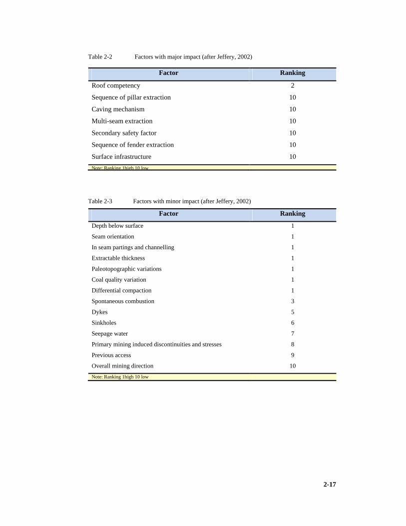
2-17
Table 2-2 Factors with major impact (after Jeffery, 2002)
Factor Ranking
Roof competency 2
Sequence of pillar extraction 10
Caving mechanism 10
Multi-seam extraction 10
Secondary safety factor 10
Sequence of fender extraction 10
Surface infrastructure 10
Note: Ranking 1high 10 low
Table 2-3 Factors with minor impact (after Jeffery, 2002)
Factor Ranking
Depth below surface 1
Seam orientation 1
In seam partings and channelling 1
Extractable thickness 1
Paleotopographic variations 1
Coal quality variation 1
Differential compaction 1
Spontaneous combustion 3
Dykes 5
Sinkholes 6
Seepage water 7
Primary mining induced discontinuities and stresses 8
Previous access 9
Overall mining direction 10
Note: Ranking 1high 10 low

2-18
Table 2-4 Factors with moderate impact (after Jeffery, 2002)
Factor Ranking
Roof discontinuities and bed forms 1
Remaining reserves 1
Interburden 1
Overburden 1
Floor competency 2
Coal strength 2
Methane 3
Joints 4
Faults 4
Sills 5
Surface subsidence 6
Aquifers 7
Standing water bodies 7
Secondary mining induced discontinuities and stresses 8
Horizontal stress 8
Time since primary extraction 9
Primary mining method and equipment 9
Adjacent panels 9
Existing bord width 9
Mining history 9
Existing pillar width 9
Coal in roof 9
Panel width 9
Previous backfilling 9
Primary mining height 9
Snook size 10
Extraction technique 10
Direction of pillar splitting 10
Secondary mining height 10
Note: Ranking 1high 10 low

2-19
2.7 Explosion Hazards
An in-goaf (goaf is the caved zone also referred to as gob) monitoring research
programme (Cook, 1999) has shown that goaf methane conditions are not as they are
commonly believed to be. Potentially explosive methane air mixtures exist in different
configurations, from narrow fringes to a few metres to very large volumes filling almost
the entire goaf strata.
Cook (1999) states, “Fringes are three dimensional extending all around the goaf, as well
as within the bottom caved zone. They are neither static nor regular making them
difficult to predict and manage. Explosive mixtures exist far into the goaf as pockets or
clouds. These remain undetected or undetectable by normal goaf monitoring methods”.
Cook (1999) reported that, “contrary to popular belief, methane does not layer or
otherwise separate from the air in a goaf. It does not flow uniformly along any parting or
dome structure to settle as a high concentration in the upper regions, neither does it all
remain in the bottom area. Concentrations are reasonably constant from the lowest to the
highest regions”.
Ventilation does not enter the goaf area to any extent but flows around and across the top
edges. This results in very little movement of the gases in the goaf and correspondingly
little removal of methane from the goaf.
Cook (1999) states that “Goafs are an integral and common part of South African coal
mining, yet the processes for mining and ventilating them remain very much based on
beliefs and assumptions rather than quantified conditions. As the seam is removed the
strata above it collapses forming permeable zones, which are ventilated to control the
build-up of methane. The methane itself layers within the goaf, rising up to higher areas,
waiting to be displaced by a sudden collapse of strata or change in atmospheric pressure.
Large volumes of methane are present in goafs, along with possible ignition sources,
either from friction or spontaneous combustion. This may well account for some of the
previously unknown sources of methane ignitions in South African collieries” (Cook,
1999).
This uncertainty as to the possible contribution played by goafs in coal mine explosions
was also highlighted by the Middelbult explosion of 1993. A major explosion occurred
in a pillar extraction panel, resulting in the deaths of 53 men and the contribution of
methane, coal dust and an ignition source from the goaf cannot be entirely ruled out.

2-20
Phillips as quoted in Cook states that “58.5% of all methane ignition sources, are
unknown for the period 1990 to 1992” (Cook, 1999). The proof of causes therefore
remains elusive.
To understand the distribution of the methane in the void, further research is needed. To
assist the understanding of the void distribution and how strata movement and collapse is
related to gas concentrations, a new monitoring method was developed in collaboration
with an equipment supplier. This is a strata anchor and extensometer, combined with the
tube bundling system.
At Twistdraai, using this equipment, it was observed that methane built up rapidly to 50%
and remained around 35% for several weeks. At Middelbult methane never went above
20% and was normal around 10%. This was associated with very low oxygen levels,
which led to the discovery of explosive gas pockets deep within the goaf. It should be
noted that these mines are in the same mining complex separated by some 10km.
Methods in collecting data were largely successful. It was found that when drilling from
surface, ahead of the goaf and installing vertical tube bundles, that most of the tubes
remained open for sampling throughout the test.
The data collected from the sites was contoured representing gas concentrations on planes
across and along the goaf. These showed the distribution of gases and the way this
changed with time.
Oxygen was often as low as 1% or 2% for reasons as yet uncertain. Results were
confirmed by laboratory analysis of gas samples. There were no CO (Carbon Monoxide)
levels to indicate a fire or heating within the goaf.
Further research (Landman, 1992) analysed the South African coal mine explosion
statistics and indicated an increase in the extent of the explosion hazard in recent years.
“The majority of explosions in South African collieries start at the coal face, where the
use of electricity, blasting and mining bit or pick friction (cutting) is responsible for most
ignitions. Consistent with experience worldwide, increased mechanisation has resulted in
an increased number of frictional ignitions at the coal face. In South Africa the problem is
aggravated by the high mineral content of and frequent sandstone intrusions into the coal
seams. In addition the hard coal results in very dusty conditions” (Landman, 1992).
Methane conditions are controlled by regulation, allowing 1.4% methane (CH4) by
volume in the air. Although the behaviour of methane is well understood, the potential of
excessive dust loading around cutting drums, especially in the form of hybrid mixtures
with methane are largely unknown. While great emphasis is placed on monitoring

2-21
respirable dust levels, total dust concentrations have not been measured or indeed
considered a potential danger by the South African coal mining industry.
Landman (1992) in his research investigated the sensitivity of ignition of those hybrid
mixtures likely to be encountered in the working face. Methane content below the lower
explosive limit of methane has been mixed with relatively low concentrations of dust, and
the minimum ignition energy determined.
“The thermal ignition theory distinguishes between the behaviour of sources of ignition
which are spatially extended and those which are spatially concentrated. In mining,
ignition from a blown out shot is more voluminous than a friction ignition and so the
explosive behaviour of both volumetric and point sources have been investigated”
Landman (1992).
“Apart from ignition source geometry, many factors influence sensitivity to ignition. In
this study most of these factors have been kept constant, but two coal types, a very
sensitive and a less sensitive coal as measured by the ‘Kex’ explosion index have been
investigated” (Landman, 1992).
“Experiments were conducted in a 40 litre explosion chamber (refer Chapter 13, Figure
13-22) and chemical and spark ignition sources were used. It was found that dust reduces
the lower explosion limit of methane and in fact such mixtures can be as sensitive to
ignition as a 5% methane air mixture. Higher fuel mixtures were required to initiate
ignition from a point source, compared with volumetric ignition, but small percentages of
methane reduced the minimum ignition energy of a dust mixture remarkably. Actual
measurements of dust loadings at coal faces have indicated that a small increase in
methane might well make the operational environment highly sensitive to ignition”
(Landman, 1992).
The thesis concluded that typical coal dust concentrations increase the chance of an
explosive event in the working face. It is recommended that collieries contain dust
concentrations at the working face within safe limits.
2.7.1 Disasters involving methane
This researcher considers the understanding of methane behaviour in goafs and the effect
of hybrid mixtures of coal dust and methane in the working place to be critically
important to the safety of high extraction operations. Explosions are immense killers and
in the spirit of zero harm need to be eliminated or at least mitigated and must be of
paramount importance on the operators list of priorities. The disasters at South Africa’s

2-22
Middelbult colliery during August 1985 (33 killed), Middelbult during May 1993 (53
killed) and New Zealand’s Pike River colliery during November 2010 (29 killed) bear
testimony to this. It should be noted that New Zealand had a similar disaster at Brunner
coal mine during March 1896 in which 65 miners were killed. Wankie colliery (now
Hwange) in Zimbabwe (ex Rhodesia) was the site of the 5th worst coal disaster in history
on 19 June 1972 (426 killed). China holds the dubious record for the number of people
killed in a single mining disaster when during April 1942, 1,572 miners were killed in an
explosion at Honkeiko coal mine. The worst mining accident in American history was
caused by an underground explosion in 1907 that resulted in the deaths of 362 miners in
Monongah, West Virginia when a year earlier in France the worst pit disaster in Europe
resulted in the deaths of 1,099 miners. A gas explosion at mount Kembla coal mine in
New South Wales killed 96 people in 1902, making it the worst industrial accident in
Australia’s history. At least 66 miners died after underground blasts at the Raspadskaya
mine in Russia (the deadliest incident in a Russian mine since 110 people were killed by a
methane blast at another mine (exact details not reported)) in the coal rich Kemerovo
region in March 2007 (www.google.co.za/en.wikipedia.org). What more needs to be said
about this threat!
2.8 New Methods and Techniques in Coal Winning
Burst reports (Kindermann et al, 1986) that in a year where world coal production
amounted to 2.9Bt (billion tonnes) (1986) the proportion from underground was about
2.1Bt. A statistical survey published shows that longwall working with a proportion of
66%, dominates underground production. Longwall mining is employed in areas such as,
West Germany, Czechoslovakia (now Czech Republic and Slovakia) and Japan. The
mean annual output however from 211 faces was 360,000t per section.
World coal (2009) reports, “hard coal production to be 5.85Bt in 2008, with China
producing 2.761Bt; USA 1.007Bt; India 0.489Bt; Australia 0.325Bt; Russia 0.247Bt;
Indonesia 0.246Bt; South Africa 0.236Bt; Kazakhstan 0.104Bt; Poland 0.084Bt;
Colombia 0.079Bt; Ukraine 0.059Bt; Vietnam 0.040Bt; Canada 0.033Bt; Germany
0.019Bt and UK 0.017Bt as sourced from IEA, Coal information, Paris 2009”. The split
between underground and surface mining is not reported (World Coal, 2009).
Face installation has been made easier due to improvements in procedures, new
equipment that is easier to assemble, new transport facilities tailored to individual
requirements and favourable heading cross-sections, even though special arrangements
2-23
such as the development of faces from gate roads or the use of trackless means of
transport will continue to be used.
In the field of face–end technology, countless solutions to individual problem areas have
been found, both support related and mechanical to boost productivity increase.
Moses (Kindermann et al, 1986) in his capacity as technical director of the National Coal
Board (UK) stated “We now have available from European manufacturers, a range of
equipment, which has been proven on coalfaces throughout the world and which have
achieved very high rates of production. The role of the European coal industry is to apply
this equipment in its best mines, selectively working its best reserves to produce coal at
costs, which can withstand the competition from other continents, and from the East. We
do not need to continue to look for other than fine adjustments of our available systems.
We must not get blinded by the technological breakthroughs that always seem to beacon
around the next bend. We must manage what we have got more effectively”
(Kindermann et al, 1986).
In South Africa more recently, a multi-year study aimed at identifying and testing new
and innovative mining methods that can be used to mine coal seams of varying thickness,
in such a way that the life of the Witbank/Highveld coalfield of South Africa will be
extended as long as economically possible, was carried out (Moolman, 2003b). Linking
the outcomes of year one’s study with a similar study undertaken in Coaltech’s Surface
Mining research area, Highwall Punch Mining was identified as a method that will be
able to achieve the life extension objective. This interim report details the progress made
to date with Highwall Punch Mining trials in South Africa. The layout involves closely
spaced parallel roadways with potential RPE strategies applied. It is also referred to as
linear mining when this layout is applied.
The bulk of South Africa’s currently economic coal reserves are found in the No.2 and 4
seams of the Witbank - Highveld coalfield. This is not surprising since the No.2 and 4
seams are the thickest, most widespread, most easily treated and most easily accessed of
the Witbank coal seams. Since these reserves are rapidly becoming depleted, it is
apparent that ways must be found of either increasing the extraction of the No.2 and 4
seams, or mining and processing the various other seams.
Increasing the extraction or production rate of the No.2 and 4 seams may negatively
affect the future minability of the associated (especially the overlying) coal seams in the
area. Generally, the other seams are also thinner and more complex. The difficulty and
the high cost associated with mining the other coal seams, which are generally thinner,
has forced the mining industry to leave vast low-seam coal reserves unmined. It is

2-24
therefore in the national interest to find cost-effective and technologically safe mining
methods for extracting narrow coal seams.
A special subcommittee (Moolman, 2003b) undertook a review of new mining practices
to identify new mining methods that will assist the industry in achieving the following
goals:
1) Improving current production rates.
2) Reducing mining costs.
3) Better utilising the available coal reserves, in both thin and higher coal seams.
The work of the sub-committee was divided into several components. Trench mining, the
hybrid Wongawilli system were identified, along with thin seam mining methods, and
international best practises for continuous mining application (CM’s), as being one of the
methods with the highest potential for assisting the South African coal mining industry to
achieve the above goals. It could also assist with the optimisation of mining under the
unique conditions encountered, i.e. weak roof and floor, leading to improved coal
extraction. However, the viability of this method needed to be confirmed regarding
production rates and cost capability. The motivation for the project was therefore to test
the method in the South African coal mining environment (Moolman, 2007).
Moolman (2007) reported that this project had not reached conclusion and had petered
out due to the sponsoring group losing interest.
This researcher understands the significance of innovative methods and technologies in
the achievement of best practice process. Already certain concepts involving linear
layouts are proving to impact internationally. The Magatar method proposed by Venter
of Magatar Mining and the reduced intersection span herring bone layout proposed by
van der Merwe hold great promise. Both methods use linear hearing bone layouts and
enhance productivity as a consequence. Magatar which uses Continuous haulage
equipment is further discussed in Chapter 9.
The coal sector is looking at clean energy and storage technologies. However, carbon
capture would be difficult for South Africa. It is not even a matter of economics. South
African geology is not conducive to carbon capture. Carbon could be stored in depleted
gas fields, at depths of more than 700m at which level carbon liquefies and one could be
fairly confident of its prolonged storage. However, all these oil and gas fields in Southern
Africa, like offshore Mossel Bay and on the offshore coast of Mozambique, are far from
the coalfields and their linked power stations. How will we get the carbon dioxide to the
gas fields? It is not feasible to store carbon down old mines – the overlying strata is
simply too porous.

2-25
The underground coal gasification technology being investigated by Eskom at Majuba is
proving viable, from a resource utilisation perspective, but that too will also have to take
into account its carbon footprint and it will have to ensure that any nearby ground water
remains uncontaminated by phenols and other contaminants.
2.9 Coal Cutting Efficiency
Marsh (1988) was concerned with an investigation into the efficiency of coal cutting and
the problems associated with this procedure. In his work, (Marsh, 1988), it was concluded
that present investigations of cutting tool efficiency are generally inadequate. By applying
the proposals as outlined in his report he concluded that improved efficiencies, lower
costs, greater productivity, less downtime and less machine wear will result.
The researcher considers wear mechanisms of cutting tools (both coal cutters and
continuous miners) such as:
1) “Frictional wear and attrition.
2) Abrasive wear and erosion.
3) Micro-fracturing and fatigue.
4) Impact damage.
5) Chemical erosion.
6) Thermal fatigue.
7) Material engineering.
8) Wear process of conical tools”.
The researcher evaluates control systems at mines. The four principle variables in coal
cutting are also identified:
1) “Cutting tool type.
2) Depth of cut.
3) Tool spacing.
4) Tool speed”.
This researcher has found that conventional blasting methods have been replaced
by mechanised coal cutting processes. The importance of this coal getting action
in effective production and world class performance is highlighted.

2-26
2.10 Practical Mine Management
A United States publication (Britton, 1981) discusses middle and front line management
in collieries. It focuses on the duties responsibilities and efforts of supervisors in both
underground and surface mining. Section two analyses the current management problems
with: costs; workers; safety; productivity; training and technical staff. He presents some
practical ideas for improving the problems.
Britton stipulates that there are at least 6,100 active coal mines in the United States of
America and he notes the short comings in young management development that exist in
the system. “The coal industry has not been successful in its efforts toward management
training and its orientation of young supervisors” (Britton, 1981).
He defines the manager as “Someone who gets things done through people” (Britton,
1981).
Effective operating techniques include all ideas aimed at improving productivity, safety
and employee relations. These have been termed the morale factors by other authors.
These include such practices as:
1) “Initiating improvement programs for employees who wanted to increase their
training, skills or education.
2) Incentive programmes for better production.
3) Incentive programmes for better safety practices.
4) Establishing communication channels beyond contract requirements to improve co-
operation (mine health and safety committees etc)”.
Britton (1981) argues the premise that in effective mines, supervisors should be equipped
with the following basic qualities: communication skills; listening skills; decisiveness;
integrity; knowledge; enthusiasm and patience.
“At the mine level, good human relations and effective management are critical to the
success of the operation” (Britton, 1981).
Modern management practices are based on the work of dozens of expert authorities, the
most familiar being Peter Drucker of Harvard University. These practices according to
(Cronje et al, 2003) incorporate the theories of Maslow (Hierarchy of needs), Festinger
(Cognitive Dissonance), Mc Gregor (Theory X/Theory Y), Blake and Mouton
(Management Grid), Hersey and Blanchard (Situational Leadership), Louis Alan
(Planning, Leading, Organising and Controlling), Crosby (Quality) and others.
Worker morale in a colliery according to Britton (1981) is influenced by:
1) “Height of the working place.

2-27
2) Presence of water or gas.
3) Roof conditions.
4) Treatment from supervisors and higher management.
5) Company policies and how they apply to the worker.
6) Fellow workers”.
Morale is a person’s mental and emotional state. It depends on or reflects the individual’s
sense of self-fulfilment. When a mine operation is analysed for its performance, the
motivation of the employees is always examined. Britton states, “Motivation is simply
the effort a person is willing to contribute towards achieving a goal. In coal mining a safe
and effective management team and a safe efficient workforce are two such goals.
Leadership is the ability to direct the activities of others. The key to leadership is co-
ordination. Co-ordination is defined, as the function of getting the right person, supplies
and equipment to the proper place at the proper time. Effective leadership is another
quality needed by supervisors” (Britton, 1981).
The first step in understanding the production problems in the mining operation is
identifying the general categories where most problems fall. Britton identifies seven
major categories: section planning; operator performance; system performance; machine
performance; system logistics; maintenance performance and safety performance.
This researcher concurs with the appreciation of the importance of the arguments
presented. These are crucial in a benchmarking study that aims to derive guidelines for
effective coal mine operation. The importance of morale and the motivation of the people
are major contributors to optimum production performance. World class systems will not
exclude these factors. The challenge lies in ensuring they are maximised and in how this
may be achieved.
2.11 Systems Thinking
Systems thinking had its foundation in the field of system dynamics, founded in 1956 by
MIT Professor Jay Forrester. Professor Forester recognised the need for a better way of
testing new ideas about social systems, in the same way we can test ideas in engineering
(Aronson, 2009).
The approach in systems thinking is fundamentally different from that of traditional
forms of analysis. Traditional analysis focuses on separating the individual pieces of
what is being studied. The word ‘analysis’ actually comes from the root meaning ‘to
break into constituent parts’. Systems thinking in contrast, focuses on how the thing

2-28
being studied interacts with the other constituents of the system. We have a set of
elements that interact to produce behaviour of the holistic system of which it is part. This
means instead of isolating smaller and smaller parts of the system being studied, system
thinking works by expanding its view to take into account larger and larger interactions as
an issue is being studied.
Examples of areas in which systems thinking has proven its value include:
1) “Complex problems that involve many participants seeing the big picture and not just
their part of it.
2) Recurring problems or those that have been made worse by past attempts to fix them.
3) Issues where an action affects (or is affected by) the environment surrounding the
issue, either the natural environment or the competitive environment.
4) Problems whose solutions are not obvious”.
By seeing the whole picture, the team is able to think of new possibilities that they had
not come up with previously, in spite of their best efforts. Systems thinking has the
power to help teams create insights when applied to a problem (Aronson, 2009).
2.11.1 Value chain analysis
Porter (Jackson, 2004) introduced a generic value chain model that comprises a sequence
of activities found to be common to a wide range of firms. Porter identified Primary and
Support activities as shown in Figure 2-1 .
Porter's Value Chain Model Figure 2-1
Figure 2-1 Porter's Value Chain Model (from Jackson, 2004)

2-29
In the model the primary activities are: inbound logistics; operations; marketing and
sales; and service. The support activities are the firm’s: infrastructure; HR management;
technology development; and procurement.
This is a system and requires an approach to analyse it. A modern scientific approach is
that proposed by Michael C Jackson (Jackson, 2004) in his work on ‘Systems Thinking’.
This applies a systems approach to management problems and classifies alternative
holistic perspectives in combination.
The Systems approach should result in:
1) “Improving goal seeking and viability.
2) Exploring purposes.
3) Ensuring fairness.
4) Promoting diversity”.
These approaches involve:
1) “Hard systems thinking.
2) System dynamics.
3) Organisational Cybernetics.
4) Complexity theory.
5) Strategic assumption surfacing and testing (e.g. killer assumptions, making
assumptions that are incorrect).
6) Interactive planning.
7) Soft systems methodology.
8) Critical system heuristics.
9) Team empowerment.
10) Post-modern systems thinking”.
Jackson puts a taxonomy perspective on systems thinking and it is this that in the opinion
of this researcher will identify the soft issues that will make a difference in mining
operations.
2.12 Quality Tools In manufacturing environments, there are many areas in which you can focus to create
improvements and systems such as the Six Sigma (section 2.12.3) and the Twenty Keys
(section 2.12.1) can help you to find a focus for improvements.

2-30
2.12.1 Twenty Keys
Kobayashi has created a list that includes these and more, and can be used in
manufacturing audits (Kobayashi, 1995). It provides a very useful checklist. The Twenty
Keys are:
1) “Clean and tidy. Everywhere and all of the time.
2) Participative management style. Working with all people to engage their minds and
hearts into their work as well as their hands.
3) Teamwork on improvement. Focused on teamwork to involve everyone in
enthusiastic improvements.
4) Reduced inventory and lead time. Addressing overproduction and reducing costs and
timescales.
5) Changeover reduction. Reducing times to change dies and machines to enable more
flexible working.
6) Continuous improvement in the workplace. Creating improvement as a ‘way of life’,
constantly makes work better and the workplace a better place to work.
7) Zero monitoring. Building systems that avoid the need for ‘machine minders’ and
instead have people who are working on maintaining a number of machines.
8) Process, cellular manufacturing. Creating interconnected cells where flow and pull
are the order of the day.
9) Maintenance. Maintaining of machines by people who work on them, rather than
external specialists. This allows constant adjustment and minimum downtime.
10) Disciplined, rhythmic working. Synchronised total systems where all the parts work
together rather than being independently timed.
11) Defects. Management of defects, including defective parts and links into
improvement.
12) Supplier partnerships. Working with suppliers, making them a part of the constantly-
improving value chain, rather than fighting with them.
13) Waste. Constant identification and elimination of things that either do not add value
or even destroy it.
14) Worker empowerment and training. Training workers to do the jobs of more highly
skilled people, so they can increase the value they add on the job.
15) Cross-functional working. People working with others in different departments and
even moving to gain experience in other areas too.
16) Scheduling. Timing of operations that creates flow and a steady stream of on-time,
high-quality, low-cost products.

2-31
17) Efficiency. Balancing financial concerns with other areas which indirectly affect
costs.
18) Technology. Using and teaching people about more complex technology so they can
use and adapt to it, bringing in the latest machines and making them really work.
19) Conservation. Conserving energy and materials to avoid waste, both for the
company and for the broader society and environment.
20) Site technology and concurrent engineering. Understanding and use at all levels of
methods such as Concurrent Engineering and Taguchi methods”.
This is a useful list, but of course it still does not include everything. A practical exercise
is to take this and use it either to evaluate a current workplace or as a discussion forum,
ensuring people understand it all contributing other areas that need to be added for a
company (Syque.com, 2009). The Keys need to be adapted for a mining system and in
this lies a challenge.
2.12.2 Total Quality Management
Total Quality Management (TQM) is a management approach or strategy aimed at
embedding awareness of quality in all organisational processes. It maintains that
organisations must strive to continuously improve these processes by incorporating the
knowledge and experiences of workers. Quality management can be explained as the
proposed action taken after finding out the difference or shortfall between the present
condition and the expected level set by any quality standards. The proposed actions or
the actual action carried out to fill the gap can be considered as quality management
practice. Although originally applied to manufacturing operations, TQM is now
becoming recognised as a generic management tool, just as applicable in service and
public sector organisations. TQM is mainly concerned with continuous improvement in
all work, from high level strategic planning and decision-making, to detailed execution of
work elements on the shop floor. It stems from the belief that mistakes can be avoided
and defects can be prevented. Continuous improvement must deal not only with
improving results, but more importantly with improving capabilities to produce better
results in the future.
Among the most widely used tools for continuous improvement is a four-step quality
model – the plan-do-check-act (PDCA) cycle (Softexpert, 2009):
1) “Plan: Identify an opportunity and plan for change.
2) Do: Implement the change on a small scale.

2-32
3) Check: Use data to analyse the results of the change and determine whether it made a
difference.
4) Act: If the change was successful, implement it on a wider scale and continuously
assess your results. If the change did not work, begin the cycle again”.
Organisations that may match or exceed the expectations of customers should use
systematic, planned and well structured processes that may contribute to improvement in
quality and the quality management. A company or any business entity that doesn’t
practice TQM may become non-competitive sooner or later and the chance of that
company or business being driven out of the market is high. Organisations today are
discovering the realities of managing a fast-moving business in a permanent system of
complex regulatory compliance. A great number of other regulations are driving
companies to implement sophisticated compliance frameworks with unprecedented levels
of time, budget and resource. Current and emerging trends suggest that the demands will
most likely become more stringent and more numerous and harder to apply within a fast-
moving business environment. However, effective compliance management will protect
and enhance the brand and reputation by helping avoid the adverse affects of non-
compliance such as: litigation; fines; prosecution; and damage to brand reputation,
associated with non-compliance. It is important to focus not just on the immediate task at
hand but also on how a business solution can support the organisation throughout the full
compliance lifecycle. A common cycle for process improvement activities that can be
applied to any business improvement initiative is the classic PDCA Cycle stated above.
Software solutions should be designed to support all phases of this cycle, from the
planning stage to the correction phase (Softexpert, 2009).
2.12.3 Six Sigma
Six Sigma is a management philosophy developed by Motorola that emphasises setting
objectives, collecting data, and analysing results as a way to reduce defects in products
and services. It is a business management strategy, which today enjoys widespread
application in many sectors of industry. Six Sigma improvements in surface mining
environments have been achieved for example:
1) Truck loading time reduced by more than 30 seconds on average.
2) Rock fragmentation improved from 90% to over 99% of material within target size.
3) Fuel consumption reduced.

2-33
4) Crusher throughput increased from 1,350 to 1,500tph, creating capacity for extra
production.
5) Fuel particle count reduced from 400,000 particles per ml to less than 2,000 particles
per ml, producing increased production through reduced equipment stoppages and
downtime.
6) Environmental haulage costs reduced.
These results are typical of what you can expect in the first 6 to 18 months of deploying
Six Sigma in a medium-size mine. These results can be achieved using basically the same
equipment and people (Aorist, 2008). The challenge is to find its suitability to
underground coal operations.
2.13 Conclusion
1) The literature review has identified pertinent factors that will form part of the
guidelines to management and operators to ensure productivity, effectiveness and
efficiency.
2) Certain critical guidelines have been identified through the research of Beukes in
the application of pillar and rib pillar extraction and will not be repeated in the
new guidelines generated but must be taken note of.

3-1
3 GEOLOGY
Geology impacts significantly on any mining method and some understanding is
important when choosing specific methods and analysing specific successes. This
dissertation identifies issues which impact on the aims of this research.
3.1 Coal and Coal Formation
Geologists concur that the coal bearing strata in South Africa occur in the Ecca Group, of
the Karoo Supergroup of rocks, which is of Permian age (Beukes, 1992). According to
de Jager occurrences of coal also manifest in the Permian and Triassic aged rocks, where
we find the younger Beaufort and Stormberg sequences (de Jager, 1976).
Rank ranges from Peat, Lignite, Bituminous, to Anthracite based on alteration and
volatile content and fixed carbon content. Beukes (1992) quoted de Jager to identify and
define rank in southern African coals, “The rank ranges from Bituminous to Anthracite,
with relatively insignificant Lignite reserves known from Cretaceous and Tertiary aged
strata. Rank is the measure of the metamorphism of the coal” (Beukes, 1992).
Anderson and Anderson (1985) argued that glaciation was wide spread as evidenced by
the Dwyka Tillite at the foundation of the Karoo rocks. This was accompanied by
continental drift and the consequent breakup of Gondwanaland. As the South Pole
moved eastwards, the ice age began to decline, glaciers reduced in size and swamps
began to form. It is recognized that this took place during Carboniferous and upper
Permian and Triassic times (Anderson, J. & Anderson, H., 1985).
Falcon (1986) referred to numerous rivers bearing fine sediments from melting glaciers
and local highlands, which meandered through the peat swamps. As the climate became
more temperate plants evolved and flourished whilst established species on the fringes of
Gondwana migrated inwards. The growth of the plant matter in the cold conditions was
slow and possibly seasonal, resulting in coal rich in oxidised plant remains and often high
in mineral matter content (Falcon, 1986). Figure 3.1 is a graphic of Gondwanaland
which was intact while the coal seams were deposited.

3-2
Gondwanaland Figure 3-1
Figure 3-1 Gondwanaland during Carboniferous and early Permian (adapted from Beukes,
1992)
3.1.1 Chronostratigraphy and lithostratigraphy
Beukes (1992) refers to a tabulation by Macgregor (1983) which relates the geological
ages with chronostratigraphy (rock strata deposited over the eons, eras, periods, epochs
and ages) and lithostratigraphy (layered rock types deposited) and stated that the
Carboniferous era took place some 280 to 345 million years ago, while the Permian
occurred some 230 to 280 million years ago. This fact is supported by (Falcon, 1986).
De Jager (1976) reported that the southern hemisphere coal was formed during the
Permian times while the northern hemisphere coals were deposited during Carboniferous
times. This era (Carboniferous) was characterised by tropical to sub-tropical climate with
regular rainfall and rapid plant growth in the waterlogged swamps on the shorelines of
warm equatorial seas.
Paleoclimatic conditions and topography influenced growth and deposition of the plants
during the period that coal was formed. Falcon argued that the chemical composition of
the coal was also influenced by these factors. The coal is composed of a number of
microscopic organic constituent’s referred to as macerals and also inorganic constituents
or minerals, which form the microscopic bands or microlithotypes and subsequently the
lithotypes.

3-3
Table 3-1 Chronostratigraphy and Lithostratigraphy (after Beukes, 1992)
Chronostratigraphic
Unit (System)
Time line
X 106 years Era Lithostratigraphic
System
Lithostratigraphic
Supergroup
Quaternary < 2 Cenozoic Quaternary Post-Karoo
Tertiary (Neogene,
Paleogene)
2 – 65 Cenozoic Tertiary Post-Karoo
Cretaceous 65 – 140 Mesozoic Cretaceous Post-Karoo
Jurassic 140 – 195 Mesozoic Karoo Karoo
Triassic 195 – 230 Mesozoic Karoo Karoo
Permian 230 – 280 Paleozoic Karoo Karoo
Carboniferous 280 – 345 Paleozoic Karoo Karoo
Devonian 345 – 395 Paleozoic Cape Cape
Silurian 395 – 435 Paleozoic Cape Cape
Ordovician 435 – 500 Paleozoic Cape Cape
Cambrian 500 – 570 Paleozoic Cape Cape
Namibian 570 – 1180 Precambrian
Neo-Proterozoic
Nama / Damara Damara
Mokolian 1180 - 2070 Meso-
Proterozoic
Nossib
Mokolian 1180 – 2070 Meso-
Proterozoic
Waterberg
Mokolian 1180 – 2070 Meso-
Proterozoic
Bushveld I C
Vaalian 2070 – 2630 Paleo-
Proterozoic
Transvaal Transvaal/Griqualand
West
Randian 2630 – 3090 Precambrian
Neoarchaen
Ventersdorp Ventersdorp
Randian 2630 – 3090 Witwatersrand Witwatersrand
Randian 2630 – 3090 Dominion Reef
Swazian 3090 – 3750 Precambrian
Mesoarchaen
Pongola
Swazian 3090 – 3750 Moodies Swaziland
Swazian 3090 – 3750 Swaziland / Kheis Swaziland
3200 Paleoarchean
3600 Ecarchaen

3-4
International Stratigraphic Chart Quartenary to Carboniferous
Figure 3-2
Figure 3-2 International Stratigraphic Chart Quartenary to Carboniferous System Period
(After the International Commission on Stratigraphy, a Geological Timescale, 2004)

3-5
Internal Stratigraphic Chart Devonian to Archean
3-3
Figure 3-3 International Stratigraphic Chart Devonian to Ecarchean System Period (after
ICS, 2004)
(After the International Commission on Stratigraphy, a Geological Timescale, 2004)

3-6
The chronostratigraphy units recognised range from youngest in Table 3-1 quoted in
(Beukes, 1992): “The International Commission on Stratigraphy has classed: Eon, Era,
Period (System), Epoch (Series) and Age (Stage),” and this has been reproduced in
Tables 3-2 and 3-3.
3.1.2 Macerals and lithotypes
Macerals are divided into three groups, Vitrinite, Exinite and Inertinite. Some common
rock forming minerals associated with the coal measures, occur as sedimentary rocks
(siltstones, shales and sandstones) and as mineral grains within the organic matrix of the
seam (quartz, clays, carbonates, sulphides and various oxides) (Falcon, L. and Falcon, R.,
1987). “Lithotypes known as Vitrain, Durain Clarain and Fusain are groups of macerals
clustered into layers of microlithotypes. Microlithotypes are in turn banded or clustered as
lithotypes” (Falcon, L. and Falcon, R., 1987).
Falcon stated (Falcon, L. and Falcon, R., 1987) that “the Inertinite group, possess the
highest hardness, Vitrinite intermediate, and Exinite the softest. South African coals are
generally hard and uncleated which makes them much more difficult to cut than northern
hemisphere (European) coals”.
Macgregor (1983) summarised the major differences between South African and
Northern hemisphere coals and referred to mineralisation, cleavage and jointing, depth to
seam and deposition climate. We note that there are differences in Vitrinite content and
qualities (Macgregor, 1983).
Table 3-2 Comparison of hemisphere coals (after Macgregor, 1983)
South African European
Deposited in a cool cold climate Sub-tropical climate
High proportion of Inertinite & detrital
materials
High proportion of Vitrinite & Exinite
Coal is jointed (little evidence of cleat) Well cleated
Shallow seams Deep seams with accompanying stress &
high cleat frequency makes cutting easier
than in South Africa
Leeder (1982) summarised the environments of deposition on the earth’s surface,
identifying; continental, coastal shelf and oceanic environmental associations (Leeder,
1982).

3-7
3.2 Resources and Reserves
The major coal deposits in South Africa occur in the main Karoo basin. The coal is found
in the Vryheid formation, formally classified as part of the Middle Ecca series of the
Karoo Supergroup. The formation is only developed in the northern part of the main
Karoo basin, north of latitude 29 degrees (Erasmus et al, 1981).
A resource is that part of a coal resource for which tonnage, densities, shape, physical
characteristics and coal quality can be estimated with a specific level of confidence.
Reserves can be defined as known amounts of economic mineral that can be profitably
produced at current prices with current technology (Beukes, 1992). A Reserve
classification is defined by the SAMREC Code in South Africa, the JORC Code in
Australia and the NI 43-101 which is the Canadian Standard. The well-known Mc
Klevey diagram, (Figure 3-4) used by the United States Geological Survey, shows the
relationship between reserves and other measures of resource stocks (Bredell, 1991).
Bredell stipulates (Bredell, 1991), “It classifies resources according to two parameters:
The degree of geological confidence and the degree of economic recoverability by
mining.”
Mc Klevey Diagram Figure 3-4
Figure 3-4 Resource and reserve classification (Mc Klevey Diagram, after US Geological
Survey)

3-8
Measured mineral resources may convert to either proved mineral reserves or probable
mineral reserves. Measured mineral resources, require considerations of the modifying
factors affecting extraction.
The modifying factors are designed to include mining, metallurgical, economic,
marketing, legal, environmental, social and governmental considerations (SAMREC
Code, 2007).
Table 3-3 Resource and reserve category (after SAMREC, 2007)
Coal Resource /Reserve
Category
Qualification Simplified Calculation
Gross Tonnes In Situ
GTIS
All coal above minimum
seam thickness and cut-
off grade
GTIS = Area [defined by minimum
seam thickness & grade] x Avg. seam
thickness x Avg. RD
Total Tonnes In Situ
TTIS
Geological & modelling
losses applied
TTIS = GTIS x [1- geological loss]x[1-
modelling loss]
Mineable Tonnes In
Situ MTIS Th.MH
(Theoretical mining
height)
Coal in area defined by
mineable seam thickness
& depth or strip ratio cut-
off. Geo & modelling
losses applied
MTISTh.MH = [Area defined by
minimum seam thickness (up to
Th.MH & grade & depth or strip ratio
cut-off]x Avg. Th.MH
thickness]x[Avg. RDTh.MH] x [1-
geoological loss]x[1-modelling loss]
Mineable Tonnes In
Situ MTISPr .MH
(Practical mining
height)
Coal in area defined by
minimum & maximum
practical mining height,
including dilution
MTISPr.MH = [Area defined by
minimum & maximum practical
mining heights (with previously
defined area less layout losses)]x[Avg.
Pr. MH Thickness]x[Avg. RDPr.MH]x[1-
geological loss]x[1-modelling loss]
Run of Mine Reserve
RoM
Extractable coal reserve
less recovery efficiency
factor including
contamination &
moisture correction
factor
RoM=([MTISPr.MH]x[Mining extraction
factor])/([1- contamination
factor]x[Mining recovery
factor]x[1+RoM moisture correction
factor])
Saleable coal reserve
Sales
Sum total of all products
after coal processing
operations
Sales =RoM x [%Yield]x[1-%Sales
moisture correction factor]

3-9
SAMREC Resource & Reserve Classification Figure 3-5
Figure 3-5 Relationship between Exploration results, Mineral Resources and Mineral
Reserves (SAMREC Code, 2007)
The relationship between resources and reserves is given in Figure 3-5. A South African
national inventory is overdue. The last was conducted in 1983 and published in 1987
(Bredell, 1987). This indicated a recoverable reserve of 55.33Bt. Some reserves have
been reclassified as reserves from resources (from 54.3 to 55.3Bt). One estimate is as low
as 33.19Bt (Prevost, 1999).
Table 3-4 Estimates of SA Coal Reserves (Jeffery, 2005)
Year Report In situ reserves (Mt) Recoverable (Mt)
1975 Petrick 82,018 25,290
1983 De Jager 115,530 58,404
1987 Bredell 121,218 54,303
Jeffery (2005) stated, “South Africa has large, although not unlimited amounts of coal.
The Witbank and Highveld coalfields are approaching exhaustion (estimated 9Mt of
recoverable coal remaining in each), while the coal quality or mining conditions in the
Waterberg, Free State and Springbok Flats coalfields are significant barriers to

3-10
immediate, conventional exploitation. New extraction technologies, technologies
exploiting the energy content of the coal in situ, as well as suitable uses and markets for
low grade, high-ash coal are required before the country can utilise its admittedly vast
coal resources. Major challenges for exploiting some Limpopo province coalfields are
severe water shortages, insufficiently developed infrastructure, fragile environments and
poor roof conditions due to depth and complex geology. In the Central Basin (Witbank,
Highveld and Ermelo coalfields) technical innovations for thin seam extraction, economic
mining of both pillar coal and intrusion fragmented resource blocks and the utilisation of
lower grade coals are required. The success of the fluidised bed combustion technology is
necessary to utilise the low grade coals of the Free State and Indwe–Molteno coalfields,
while environmental exemption for past problems, together with strategies for mining
small, disjointed thin seam resource blocks is required in KwaZulu-Natal. Clean coal
technologies, coal cost and quality, environmental considerations, sustainable
development, the growth of the South African economy and Government’s regulation of
the electricity industry are the main challenges to the continued use of coal as South
Africa’s primary energy source” (Jeffery, 2005).
3.3 Coalfields in Southern Africa
This research will identify only the most significant fields with the best potential at the
time of this study. The Botswana fields provide a promising future. There are some
untapped deposits in Mozambique and also the remnants of the Wankie field (Hwange) in
Zimbabwe.
The Highveld coalfield, of South Africa, covers approximately 7,000km2 and is situated
in the Mpumalanga Province (Beukes, 1990). Many of the best producing underground
sections in South Africa are situated in this field. Large collieries producing more than
10Mtpa saleable coal are found in this field. They are amongst others Matla, Kriel,
Bossjesspruit, Twistdraai, Brandspruit, Syferfontein, Middelbult, New Denmark and
Khutala which is on the boundary with the Witbank field.
Beukes (1990) found that, “at a majority of collieries, the strata overlying the 4 Seam,
which is the major seam of economic importance, is thick competent sandstone, which
generally forms a good roof” (Beukes, 1990). The competent sandstone however does
not cave readily during pillar extraction especially in narrow panels. This causes stress
increases on the partially extracted pillars and can cause premature failure of the
remnants. Goaf over runs of pillar and breaker lines may occur when the roof caves. The
4 Seam is split by a parting which increases in thickness from 2m to 15m. The 4 Upper

3-11
only attains mineable thickness in limited areas of the western part of the field. The 4
Lower is well developed over large areas, with an average mineable thickness of
approximately four metres. De Jager (1976) confirmed that “the 4 Lower is of great
importance to the Republic of South Africa, which with the exception of the Waterberg
Coalfield is the only coalfield that can readily satisfy a large future demand” (de Jager,
1976).
Jordaan referred to in Beukes studied the occurrence of igneous intrusives of the
Drakensberg formation, in the form of Dolerite sills and dykes, which cover large areas of
the Highveld coalfield. “The sills are up to 90m thick and consist of composite sills or a
series of splits. The splits are up to 40m thick. These sills have been observed to
transgress the coal seam in various places resulting in the formation of burnt and
devolatilised coal and the displacement of the seams in various places, especially in the
central and southern parts. Numerous dolerite dykes varying in thickness from a few
centimetres to several metres, have been encountered in the coalfield. They have a major
influence on mine layouts and the type of mining methods that can be used cost
effectively” (Beukes1989a).
The Number 1 and 3 Seams are thin and discontinuous throughout the coalfield and
currently not considered mineable although thin seam mechanised methods are being
evaluated.
Beukes states “The 2 Seam is thick and economically extractable at some collieries such
as Matla, Kriel and Middelbult, while the 5 seam is only extractable at Matla and Kriel”
(Beukes, 1990). “The 2 Seam is thick (up to 8m) and laterally continuous. The
immediate roof is variable and can consist of sandstone, mudstone and siltstone. The
sandstone forms a good roof but the other types of roof require systematic support. The
variation in the floor strata is similar to the roof strata. The sandstone forms a good floor,
but the other rock types break up under heavy mining equipment, especially in the
presence of water” (Beukes, 1990).
The research by (Beukes, 1992) identifies fields, which have to date played a very
important role in the South African coal mining history but are or have approached
reserve depletion. Remnants are still being exploited in certain areas but the balance of
the resource will only be recoverable through new economic structures and new
technologies.
South Africa has 17 identified coalfields, (de Jager, 1976). Beukes has reported only on
the economically significant and active fields at the time and it is noted that this excludes
the Waterberg Coalfield. Beukes referred to the Highveld, Eastern Transvaal, Utrecht,

3-12
Klip River, Zululand, Vereeniging – Sasolburg, and Springs–Witbank coalfields (Beukes,
1992) .
3.3.1 The significance of the Waterberg and Botswana
coalfields
Galvin in a work on the mining of South African thick coal seams, reported, “the
Waterberg coalfield is very remote to South Africa’s major industries and services and no
coal mining operations of any consequence have been developed in the field. Economic
considerations associated with the considerable depth of the seams, coal quality and
remoteness restrict future mining operations in this coalfield” (Galvin, 1981). Since
Galvin’s publication a surface open–pit truck and shovel operation, Grootegeluk Colliery,
has been established in the shallower part of the field near Ellisras. The operation
requires extensive coal preparation to get product to market specification.
The Waterberg extends into Botswana where the prefeasibility study for Mmamabula
colliery had been conducted during 2008.
Further north towards Palapye a feasibility study has been completed during 2010 for the
expansion of Morupule colliery and to exploit the thick Morupule seam. A total
unpublished resource, for Botswana of about 37Bt, has been reported by exploration
geologist G van Heerden, of SRK Consulting (van Heerden, 2008).
Table 3-5 Coal zones in the Waterberg as exposed at Grootegeluk (Adamski, 2003)
Bench RD Thickness (m) Description Group
1 2.51 16.5 Overburden Upper Ecca
2 1.74 13.5 Bright coal Upper Ecca
3 1.83 16.0 Bright coal Upper Ecca
4 1.86 16.0 Bright coal Upper Ecca
5 1.90 16.7 Bright coal Upper Ecca
6 1.67 4.2 Dull coal Middle Ecca
7A 2.41 5.7 Shale Middle Ecca
7B 1.58 1.6 Dull coal Middle Ecca
8 2.41 3.9 Shale Middle Ecca
9A 1.58 2.8 Dull coal Middle Ecca
9B 1.58 5.3 Dull coal Middle Ecca
10 2.49 3.9 Sandstone Middle Ecca
11 1.52 4.1 Dull coal Middle Ecca
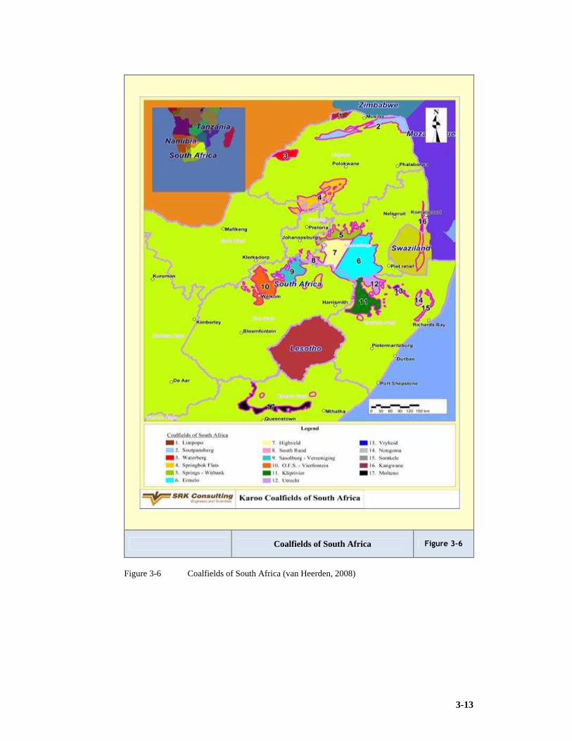
3-13
Coalfields of South Africa Figure 3-6
Figure 3-6 Coalfields of South Africa (van Heerden, 2008)

3-14
Stratigraphy Morupule Coalfield Figure 3-7
Figure 3-7 Stratigraphy of the Morupule coalfield Botswana (van Heerden, 2008)
Botswana Coalfields Figure 3-8
Figure 3-8 The Botswana Coalfields (van Heerden, 2008)

3-15
Various coalfield stratigraphies and localities are displayed Figures 3-6 to 3-8 and Table
3-5 depicts the Waterberg lithology at Grootegeluk colliery.
3.3.2 The importance of the Witbank and Highveld coalfields
Galvin (1981) reported on geological conditions and classification systems pertaining to
floor strata, coal strata, immediate roof strata and upper roof strata. Galvin focused on
the seams suitable for thick seam mining and studied the Springs – Vischkuil – Witbank,
the Highveld, the South Rand and the Vereeniging – Sasolburg coalfields (Galvin,
1981).
Jeffery (2002) in a study of geotechnical factors associated with previously mined out
areas, reported on variables referred to as classes and their impacts on rock mass
behaviour, roof support and flammable gas. Jeffery has identified the following classes
or categories: Statigraphy; Rock Engineering Properties; Spontaneous Combustion;
Discontinuities; Igneous Intrusions; Collapse of previous workings; Hydrology; Stress
Environment; Primary Mining Parameters and Secondary Mining Parameters. Jeffery
further refers to impacts; roof caving potential; rock burst potential; rib and pillar
stability; floor heaves; roof surface subsidence; mine scale roof support; panel scale roof
support; gas conditions and spontaneous combustion. Her study has found that the
remaining reserves in the northern section of the Witbank and Highveld coalfields were
recently estimated to be approximately 14Bt mainly in the 2 and 4 Seams (5 and 4Bt
respectively). This translates to approximately 5Bt of mineable in situ reserves, divided
1:2 between opencast and underground reserves.
Run of mine reserves amount to just over 3Bt, however just less than 1Bt of this saleable
reserve estimate is attributable to export quality coal (that is coal with a calorific value of
more than 24MJ/kg) (Jeffery, 2002). Lurie (1976) is the source of the coalfield
stratigraphy depicted in the Figures 3-9 and 3-10.
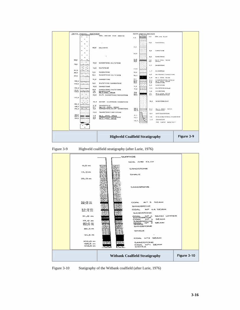
3-16
Highveld Coalfield Stratigraphy Figure 3-9
Figure 3-9 Highveld coalfield stratigraphy (after Lurie, 1976)
Witbank Coalfield Stratigraphy Figure 3-10
Figure 3-10 Statigraphy of the Witbank coalfield (after Lurie, 1976)

3-17
3.4 The Significance of Pillar Coal
Jeffery (2002) stated, “The majority of export collieries will cease production by the late
2020’s. There is thus a looming shortage of export coal, the 3rd largest earner of foreign
exchange for South Africa. However, with the majority of mining in the Witbank area
being bord and pillar extraction, significant volumes of coal have been left behind as
pillars and barrier pillars. These are currently an unexploited resource, which includes
export quality coal. The coal industry may shortly be forced to seriously consider
extensive secondary extraction in order to boost export resources” (Jeffery, 2002).Various
researchers have attempted to quantify the amount of coal remaining in pillars in South
Africa. Hardman (2001) estimated 1.7Bt of coal in four million pillars over an area
measuring 32km x 32km (Hardman , 2001).
Lind (2004) quoted Canubulat who estimated the amount of residual pillar coal during
1997, using bord and pillar dimensions for 350 panels in South Africa. The average
dimensions were bord width 6m, pillar width 15m, mining height 2.8m. Baxter (1998)
calculated the amount of pillar coal at 113.4Mt derived from a volume of 70.9Mm3 and a
density of 1.6tpm3. Baxter concludes “that 6.7Mt of pillar coal could be mined each year
for 17 years at 100% extraction” (Baxter, 1998). This could be considered a medium to
large mining operation.
Secondary extraction is only possible where the primary extraction was by the bord and
pillar method. The mining method chosen will depend on a variety of geotechnical
factors. Where either method is suitable the decision will be based on economics.
Jeffery (2002) aims at identifying and quantifying those critical geotechnical factors that
impact on the secondary extraction of coal in the Witbank coalfield of South Africa.
Although the initial study is concentrated in this region, findings could potentially be
applicable to other South African coalfields.
3.5 The Significance of Increased Extraction
Information on the extent of the South African reserve is further elucidated on by Lind
and Phillips. “The use of bord and pillar mining (using pillar design formulae) still only
extracts approximately half of a reserve, thus leaving half in the form of pillars. It is
estimated that at 2001 levels of extraction the coal mining industry in South Africa had a
life expectancy of 25 years based on the available data at the time” (Lind and Phillips,
2001).

3-18
Lind (2004) reported in his research on the development of a design methodology and
planning tool to increase the utilisation of coal resources in the Witbank and Highveld
coalfields through underground pillar extraction, that, “The most obvious potential for
increasing the overall utilisation of coal resources in the Witbank and Highveld coalfields
(which contributed 80% of all South Africa’s coal production in 2000) and thus
sustaining South Africa’s second largest export after gold, is the safe and economic
extraction of these pillars created by bord and pillar methods. More importantly the
increased utilisation of the coal resources in these coalfields will ensure that the coal fired
power stations situated on these coalfields will be sustainable to the end of their lives (as
these power stations still have a life span of approximately 30 years)” (Lind, 2004).
3.6 The Potential of Discard Coal Products
An annual rate of production is discussed by, Wagner (1998) “Approximately 262Mt of
run of mine coal was produced in South Africa in 1996, of which 55Mt were discard coal
products (fine and coarse discard, slurry and unsold duff). With a limited amount of
economically viable coal reserves in South Africa it is becoming increasingly important
to consider the discards and currently unmarketable resources as vital energy sources”
(Wagner, 1998). During 2009 this figure was around 65Mt for a production of around
235Mt.
3.7 Technical Challenges Presented by the Southern
Hemisphere Coals
Van Zyl (2003) quotes Dave Hardman’s (of the University of Witwatersrand) letter to
Sasol on the cutability of South African coals, supporting the general perception that the
cutability is more difficult than that of Northern hemisphere coals, “Our coals are
generally more abrasive than those found in other coal producing countries making use of
continuous miners; we have problems with sandstone intrusions, floors and roofs. The
combined factors can result in the generation of picks so badly worn that on occasion it is
amazing that the continuous miners can still cut. In general I do not believe that other
coal producing countries have the same problems as ourselves, which means that we need
to devise our own solutions. One of the solutions to overcome cutting problems over
time has been the construction of heavier and more powerful machines” (van Zyl, 2003).

3-19
Adamski (2003) recorded that, the Waterberg coalfield is significant but presents some
technical challenges, “The coal field is relatively small in area but one of the most
important coalfields in the Republic of South Africa containing approximately about 50%
of the coal reserves of South Africa. The coalfield is bounded by faults along its northern
and southern limits with displacement. The Daarby fault with a displacement of 250m,
divides the Waterberg coalfield into two areas: a shallow, western area, where the coal
can be extracted by surface mining and; a deep, north-eastern area, where the coal occurs
at a depth of at least 270m. The coal seams mined at Grootegeluk (based in the shallow
area), are part of the Ecca Group and 11 coal zones can be distinguished. The upper Ecca
is on average 60m thick and consists of successions of inter-bedded shale and bright coal
(barcode formation). It is a typical multi-seam deposit consisting of coal beds varying in
thickness from a few centimetres to just over a metre, closely interbedded with mudstone
over the total thickness of 60m. The middle Ecca is on average 50m thick and forms the
lower part of the deposit consisting of dull coal and carbonaceous shale, as well as grit
and sandstone” (Adamski, 2003). The challenge lies in the mining methodology decided
on for the Waterberg Coalfield.
3.8 Conclusions
1) South Africa has good resources exceeding 27Bt. Some authors maintain that this
figure is over estimated and is only about 15Bt. An updated study is definitely
required.
2) Export resource tonnages are depleting rapidly.
3) Questions have arisen on the life of existing fields and the debate needs to be
resolved.
4) Resources with strong potential exist in South Africa’s immediate neighbours
namely, Botswana and Mozambique.
5) In general the geology of the South African coalfields is favourable compared to
other countries. The seams are thick, have good roof and reasonable floor conditions.
6) Some areas have dolerite sills capping the area and impact on high extraction
exploitation.
7) Coal qualities are very suitable for power station feed.
8) Metallurgical grade (blend coking coal) may only exist in thinner 5 seam resources or
in the “bar-coded” deposits of the Waterberg, the Springbok flats and the Tete
3-20
deposits or in the mining and economically challenging deposits due to depth and
faulting of the Soutpansberg.
9) Botswana is equipped with medium quality 20 to 24MJ/kg resource with exceptional
mining conditions (good conditions).
10) The Waterberg will present significant mining challenges.
11) The mining challenges are also evident in the Tete province of Mozambique, where
multiple thin seams are interspersed with sandstones, mudstones, siltstones and
shales. This is made worse with infrastructure problems.
12) South Africa will need to consider the exploitation of thin seams to maintain
productivities.
13) As reported in Chapter 2, South African reserves account for 6.1% of total known
world reserve and at the time of the study is ranked 8th (SAMI, 2007).
14) Recoverable reserves according to Bredell (1987) are 55.3Bt (In situ 121.2Bt).
15) Recoverable reserves according to De Jager (1983) are 58.4Bt (In situ 115.5Bt).
16) Recoverable reserves according to Petrick Commission (1975) are 25.2Bt (In situ
82.0Bt).

4-1
4 HYDROGEOLOGY
Hydrogeology is a science developed for simulating the groundwater flow and
investigating the response of complex groundwater systems (Annandale, 2006).
4.1 Hydrologic Cycle
Annandale describes the hydrologic cycle as, “the hydrologic cycle is a constant
movement of water above, on and below the earth's surface. It is a cycle that replenishes
groundwater supplies. It begins as water vaporises into the atmosphere from vegetation,
soil, lakes, rivers, snowfields and oceans (a process called evapotranspiration). Surface
runoff eventually reaches a stream or other surface water body where it is again
evaporated into the atmosphere. Infiltration, however, moves under the force of gravity
through the soil. If soils are dry, water is absorbed by the soil until it is thoroughly
wetted. Then excess infiltration begins to move slowly downward to the water table.
Once it reaches the water table, it is called ground water. Groundwater continues to move
downward and laterally through the subsurface. Eventually it discharges through hillside
springs or seeps into streams, lakes, and the ocean where it is again evaporated to
perpetuate the cycle” (Annandale , 2006).
4.2 Ground Water and Subsurface Water
Most rock or soil near the earth's surface is composed of solids and voids. The voids are
spaces between grains of sand, or cracks in dense rock. All water beneath the land surface
occurs within such void spaces and is referred to as underground or subsurface water,
“Subsurface water occurs in two different zones. One zone, located immediately beneath
the land surface in most areas, contains both water and air in the voids. This zone is
referred to as the unsaturated zone. Other names for the unsaturated zone are zone of
aeration and vadose zone. The unsaturated zone is almost always underlain by a second
zone in which all voids are full of water. This zone is defined as the saturated zone. Water
in the saturated zone is referred to as groundwater and is the only subsurface water
available to supply wells and springs. Water table is often misused as a synonym for
groundwater. However, the water table is actually the boundary between the unsaturated
and saturated zones. It represents the upper surface of the ground water. Technically
speaking, it is the level at which the hydraulic pressure is equal to atmospheric pressure.”
The water level found in unused wells is often the same level as the water table
(Annandale , 2006).

4-2
4.2.1 Aquifers and confining beds
All geologic material beneath the earth's surface is either a potential aquifer or a
confining bed. “An aquifer is a saturated geologic formation that will yield a usable
quantity of water to a well or spring. A confining bed is a geologic unit which is
relatively impermeable and does not yield usable quantities of water. Confining beds also
referred to as aquitards, restrict the movement of groundwater into and out of adjacent
aquifers. Groundwater occurs in aquifers under two conditions: confined and unconfined.
A confined aquifer is overlain by a confining bed, such as an impermeable layer of clay
or rock. An unconfined aquifer has no confining bed above it and is usually open to
infiltration from the surface. Unconfined aquifers are often shallow and frequently overlie
one or more confined aquifers. They are recharged through permeable soils and
subsurface materials above the aquifer. Because they are usually the uppermost aquifer,
unconfined aquifers are also called water table aquifers. Confined aquifers usually occur
at considerable depth and may overlie other confined aquifers. They are often recharged
through cracks or openings in impermeable layers above or below them. Confined
aquifers in complex geological formations may be exposed at the land surface and can be
directly recharged from infiltrating precipitation. Confined aquifers can also receive
recharge from an adjacent highland area such as a mountain range. Water infiltrating
fractured rock in the mountains may flow downward and then move laterally into
confined aquifers.” Windows are important for transmitting water between aquifers,
particularly in glaciated areas such as the Puget Sound region. A window is an area where
the confining bed is missing. The water level in a confined aquifer does not rise and fall
freely because it is bounded by the confining bed-like lid. Being bounded causes the
water to become pressurised. In some cases, the pressure in a confined aquifer is
sufficient for a well to spout water several feet above the ground. Such wells are called
flowing artesian wells. Confined aquifers are also sometimes called artesian aquifers
(Annandale , 2006).
4.2.2 Ground water recharge and discharge
Annandale wrote “Recharge is the process by which ground water is replenished. A
recharge area is where water from precipitation is transmitted downward to an aquifer.
Most areas, unless composed of solid rock or covered by development, allow a certain
percentage of total precipitation to reach the water table. However, in some areas more
precipitation will infiltrate than in others. Areas which transmit the most precipitation are
often referred to as "high" or "critical" recharge areas. How much water infiltrates

4-3
depends on vegetation cover, slope, soil composition, depth to the water table, the
presence or absence of confining beds and other factors. Recharge is promoted by natural
vegetation cover, flat topography, permeable soils, a deep water table and the absence of
confining beds. Discharge areas are the opposite of recharge areas. They are the locations
at which groundwater leaves the aquifer and flows to the surface. Ground water discharge
occurs where the water table or potentiometric surface intersects the land surface. Where
this happens, springs or seeps are found. Springs and seeps may flow into fresh water
bodies, such as lakes or streams, or they may flow into saltwater bodies” (Annandale ,
2006).
4.2.3 Ground water movement
Ground water movement is enabled through gravity, to quote Annandale, “gravity is the
force that moves groundwater which generally means it moves downward. However,
groundwater can also move upwards if the pressure in a deeper aquifer is higher than that
of the aquifer above it. This often occurs where pressurised confined aquifers occur
beneath unconfined aquifers. A groundwater divide, like a surface water divide, indicates
distinct groundwater flow regions within an aquifer. A divide is defined by a line on the
either side of which ground water moves in opposite directions. Groundwater divides
often occur in highland areas, and in some geologic environments coincide with surface
water divides. This is common where aquifers are shallow and strongly influenced by
surface water flow. Where there are deep aquifers, surface and groundwater flow may
have little or no relationship” (Annandale , 2006).
He continues to quantify the flow rates and define porosity “the velocity at which
groundwater moves is a function of three main variables: hydraulic conductivity,
(commonly called permeability) porosity, and the hydraulic gradient. The hydraulic
conductivity is a measure of the water transmitting capability of an aquifer. High
hydraulic conductivity values indicate an aquifer can readily transmit water; low values
indicate poor transmitting ability. Because geologic materials vary in their ability to
transmit water, hydraulic conductivity values range through 12 orders of magnitude.
Some clays, for example, have hydraulic conductivities of 0.000,000,01 centimetres per
second (cmps), whereas gravel hydraulic conductivities can range up to 10,000cmps.
Hydraulic conductivity values should not be confused with velocity even though they
appear to have similar units. Centimetre per second, cmps, for example, is not a velocity
but is actually a contraction of cubic centimetres per square centimetre per second
(cm3pcm2.s). In general, course-grained sands and gravels readily transmit water and have

4-4
high hydraulic conductivities (in the range of 50 -1,000mpday (metres per day)). Fine
grained silts and clays transmit water poorly and have low hydraulic conductivities (in the
range of 0.001- 0.1mpday). The porosity of an aquifer also has a bearing on its ability to
transmit water. Porosity is a measure of the amount of open space in an aquifer. Both
clays and gravels typically have high porosities, while silts, sands, and mixtures of
different grain sizes tend to have low porosities” (Annandale , 2006).
4.2.4 Acid rock drainage
Kurt identifies acid rock drainage as, “acid rock drainage (ARD) typically represents the
most significant mining-related impact (to water resources) due to the presence of
sulphides. The exposure of the sulphides to air and moisture allows for the autocatalytic
reactions, which typically can lead to low pH values and high concentrations of dissolved
metals” (Kurt et al, 2006).
4.3 Definitions and Governing Equations
An aquifer is an underground formation of specific dimensions, which contains
groundwater that can be extracted under the influence of gravity. There are various
formulae and constants used for the calculations:
1) Reaction of the groundwater system to external influences.
2) Non-steady groundwater flow rate.
3) Flow rate of chemical substance through the aquifer.
“Through the application of the equations, one can study the rate of movement of a
pollutant, the amount of dispersion and convection in the system as well as the chemical
reaction that may take place” (Annandale , 2006).
Kurt states “Since permeability characteristics and the amount of water in an aquifer may
change, computer simulation programmes are used for the calculations (Kurt et al, 2006).
4.4 Groundwater in the South African Coalfields
In the South African Coalfields, groundwater is associated mainly with the dolerite dykes,
dolerite sills, and sandstones. The shale normally is impervious to water, except in
instances of severe structural disturbances, for instance in the vicinity of faults and dykes
(Kurt et al, 2006).

4-5
4.4.1 Groundwater associated with dolerite dykes
Kurt concludes that, “Where cracks penetrate the dolerite dykes the circulation of
groundwater, almost without exception, has created zones of chemical weathering along
the sides of the dyke. The weathering is a function of the depth of groundwater
circulation and normally pinches out at depths beyond 60m. Typical yields from
boreholes in weathered zones range from 10 to 30lps (litres per second). Sustained yield
from these structures is a function of the length of the dyke and leakage of groundwater
from the adjacent sediments” (Kurt et al, 2006).
4.4.2 Groundwater associated with dolerite sills
Dolerite sills are underlying intrusive bodies that follow specific horizons in the Karoo
Sediments for very long distances and can penetrate at angles of up to 85º to the
horizontal according to Kurt et al (2006). Owing to a lack of groundwater circulation at
depth, very little groundwater is normally encountered along the flat lying portions of the
sills (Kurt et al, 2006).
4.4.3 Groundwater associated with sandstones
Kurt concludes, “groundwater in sandstones may be contained within pores in the
sandstone. Sandstone contains almost 99% of the water due to retention forces. The
permeability of sandstone is extremely low. Owing to the weight of overlying rocks
cracks in the sandstone tend to close up at depths in excess of 60m. Therefore sandstone
cracks do not have a significant influence on coal mining operations since most of the
operations take place at depths of 100 – 180m. The only problem is boreholes penetrating
the sandstones. This is the only place where water will come out” (Kurt et al, 2006).
4.4.4 Groundwater associated with shales
Most miners would have noticed where they have exposed shales in the floor that these
are water retarding and presently tend to break up and deteriorate. Kurt comments, “the
shale above and below the coal seams generally are impervious to groundwater. These act
as confining layers, separating one sandstone from another. The groundwater within the
different sandstones therefore can be regarded as separate occurrences, each with its own
hydraulic potential, separated by impervious layers of shale” (Kurt et al, 2006).

4-6
4.4.5 Groundwater associated with pre - Karoo rocks
Kurt notes, “The various coalfields are underlain by rocks consisting of different
compositions. Whatever water may be encountered in these rocks must be contained in
cracks, joints, fractures and faults. Therefore it is unlikely for water to cause any
problems during mining operations” (Kurt et al, 2006).
From the perspective of this researchers mining experience this seems a valid conclusion.
The only significant strata water freed during mining operations has been in wall faces
with which the researcher was involved. The water is liberated as a consequence of the
caving and fracturing of the dolerite sill present.
4.5 Characteristics of the Highveld and Witbank Coalfield
Aquifers
Three distinct superimposed groundwater systems are present in the Mpumalanga
coalfields. They are the upper weathered Ecca aquifer, the fractured aquifers within the
unweathered Ecca sediments, and the lower aquifer below the Ecca sediments. The Ecca
sediments are weathered to depths of between 5 and 12m below the surface throughout
the area. The upper aquifer is associated with this weathered zone and water is often
found within a few metres below surface. This aquifer is recharged by rainfall. The
percentage recharge to this aquifer is estimated to be in the order of 1 to 3% of the annual
rainfall, based on work in other parts of the country by Kirchner during 1991 and
Bredenkamp during 1978 (Kurt et al, 2006).
Observed flow in the catchment confirmed isolated occurrences of recharge values as
high as 15% of the annual rainfall as reported by Hodgson during 1998 (Kurt et al, 2006).
It should, however, be emphasized that in a weathered system, such as the Ecca
sediments, highly variable recharge values can be found from one area to the next. This is
attributed to the localised impact of mining and the composition of the weathered
sediments, which range from coarse grained sandstone clay. The aquifer within the
weathered zone is generally low yielding (range 100 to 2,000lph (litres per hour)) because
of its insignificant thickness. The good quality of this groundwater can be attributed to the
many years of dynamic groundwater flow through the weathered sediments. Leachable
salts in this zone have been washed from the system and it is only the slow decomposition
of clay particles, which presently releases some salt into the water (Kurt et al, 2006).
The fractured Ecca aquifers are comprised of un-weathered Ecca sandstones and shales,
where fractures are the principal controls on groundwater movement. The pores within

4-7
the Ecca sediments are too well-cemented to allow any significant flow of water. All
groundwater movement therefore occurs along secondary structures, such as fractures and
joints in the sediments. These structures are better developed in competent rocks, such as
sandstone, hence the better water-yielding properties of these rocks. At depths below
30m, water-bearing fractures with significant yields were observed to be spaced at 100m
or greater distances. Of all the un-weathered sediments in the Ecca, the coal seams often
have the highest hydraulic conductivity.
Below the Ecca sediments, the Dwyka Tillite has very poor aquifer properties. These
aquifers need not be included in the modelling of the impact of mine-water irrigation, as
the weathered and fractured aquifer will mainly transport any salt emanating from
irrigation activities (Kurt et al, 2006).
4.6 Effect of Increased Extraction on Groundwater
Increased underground extraction of coal often results in a collapse of the overlying
strata. The degree of collapse primarily is a function of the competence of the overlying
strata. The effect of increasing the extraction on the overlying strata can be explained as a
continuous sequence of events (Kurt et al, 2006):
1) Shale and sandstone will collapse immediately after the support is removed.
2) Where a dolerite sill is present, the effects will be dampened and will be visible on
surface only after an area of at least 200m x 100m has been excavated.
3) Now the cracks will penetrate the overlying rocks and will increase the permeability
thereof.
4) With an increase in advance, further cracks will be generated and the inflow of water
increased.
5) Surface cracks are generally of circular nature and could be regularly spaced. It can
also have an irregular pattern.
6) It is anticipated that the degree of fracturing of the overlying rocks decreases
progressively upwards, until single cracks show on surface.
The influx of groundwater can cause serious problems. Four stand out from the
others:
1) Flooding hazard, but also difficulty in handling wet coal.

4-8
2) Water influx will continue for long periods and therefore depleting boreholes in
surrounding areas.
3) Contamination of water in boreholes.
4) Rainfall will restore initial quantities of water.
4.6.1 Rate of groundwater influx into areas of increased
extraction
The rare of groundwater influx into areas of increased underground extraction of coal is
determined mainly by three conditions (Kurt et al, 2006):
1) “The major contributing factor undoubtedly is the rate at which groundwater can
move through the unfractured rock rocks surrounding the area of increased extraction.
2) Variation in the storage coefficient or specific yield can also have an influence on the
rate of influx from surrounding rocks.
3) Predicting the initial influx into areas of increased extraction is the degree of
fracturing of the overlying rocks”.
Kurt explains that “the parameter values of transmissivity, the storage coefficient and the
specific yield can be determined by field investigations. Numeric modelling can also be
used for the simulation of the flow of the groundwater. One cannot use the hyrogeological
information from one mine for another even though the geological conditions on a
regional scale are similar. Dolerite intrusions complicate the calculation of influx rates to
a large extent. The weathered zones adjacent to the dolerite dykes and steep dipping sills
act as highly permeable channel ways for groundwater. Theoretically, the rate of influx
into a specific area should decrease with time, because there is a finite amount of
groundwater in the system. However, groundwater is recharged annually with rainfall”
(Kurt et al, 2006).
4.6.2 Rate of dewatering overlying and adjacent sediments
Kurt identifies, “three main factors control the rate of the dewatering of overlying and
adjacent sediments in areas of increased extraction:
1) Variations in the value of transmissivity.
2) Storage coefficient and the specific yield.
3) Recharging to the groundwater system.

4-9
In practice a significant variation in the transmissivity, storage and recharge values can be
expected. The recharge of the groundwater system is largely dependent on the rainfall
pattern and the permeability of the surface formations. Numerical modelling will
accommodate for any of these changes when simulations are done. Another factor
complicating calculations of dewatering cones is the fact that in many of the coalfields
numerous sandstone layers, each separated from one another by impervious layers of
shale, are present” (Kurt et al, 2006).
4.6.3 Chemical contamination of groundwater in areas of
increased extraction
The reaction with pyrites leads to acid formation, Kurt states, “as a result of fracturing of
the layers overlying areas of increased extraction, this water is exposed to fragments of
shale, sandstone, dolerite and coal. The sandstones and dolerites are inactive chemically
and have very little effect on possible chemical changes. Shales might result in reacting
with chemicals in the water. This will result in elements going into solution once the
water flows over it. That is why water arriving at a mine will have a different chemical
composition compared to the initial composition. Acids may form from these elements in
the water reacting to the pyrites. The contamination of groundwater during influx into
areas of increased extraction must not be confused with groundwater that siphons into the
mine through natural cracks. In old mines, contaminated water may be stored
underground, but on new mines this water must be disposed of on surface” (Kurt et al,
2006).
4.6.4 Isolation of areas in which increased extraction has
ceased
The engineer will have to be cautious when designing groundwater control systems as
the team of hydrologists are quoted, “groundwater will continue to flow into areas in
which increased extraction has ceased. This influx will continue until the original
hydraulic balance between the water table in these areas and in the surrounding areas has
been reached. This can be a very costly problem in the long run. Therefore proper
planning is required especially for the possibility of installing water doors and pump
stations. One needs to take special care with regard to the water reticulation system and
ensure that the flooding procedures accommodate the required influx of groundwater”
(Kurt et al, 2006).

4-10
4.6.5 Recommendation for handling groundwater in areas of
increased extraction
There are various solutions for the handling of groundwater in areas where extraction has
been increased. It is extremely important to find the correct manner of handling
groundwater as soon as possible (Kurt et al, 2006):
Drainage by surface boreholes
“It will be possible to drain groundwater in areas surrounding increased extraction
operations by drilling surface boreholes into mine development. Each hole will have to be
cased with a perforated casing and the water that drains into the mine development can be
used for mining operations or pumped to surface.
Selective increased extraction with geological compartments
Closed geological compartments occur within the coalfields. Any dewatering taking place
within such a compartment will not spread beyond the boundaries of the compartments.
Increased extraction should be conducted in these compartments as far as possible and
will result in dewatering these compartments” (Kurt et al, 2006).
4.7 Desalination of Pollute Groundwater
Desalination of contaminated groundwater has not been developed to such an extent that
this can be a consideration in the treatment of the polluted groundwater. This normally
involves the addition of lime on large scale where the ground water has been exposed.
4.8 Effects of Increased Underground Extraction on the
Environment
Increased underground extraction has a serious influence on the topography, surface
runoff, disposal of contaminated water and the effect on surface vegetation. Kurt states in
sections 4.8.1 to 4.8.4:
4.8.1 Effect on the topography
“The mining depth, thickness of the coal seam and the lithology of the overlying strata
are the major controlling factors that determine the effect of increased extraction on the
topography” (Kurt et al, 2006).

4-11
4.8.2 Effect on surface runoff
“Surface runoff will be affected by increased underground extraction in two ways. First
of all, increased infiltration of rainfall will result in areas where cracks extend up to the
surface. Secondly, in areas of flat surface topography, pans will develop above areas of
increased extraction” (Kurt et al, 2006).
4.8.3 Disposal of contaminated water
“All contaminated water needs to be treated to such an extent that it will be safe to
dispose of the water in rivers and dams. Otherwise one will have to construct surface
structures to ensure evaporation” (Kurt et al, 2006).
4.8.4 Effect of increased extraction on surface vegetation
“The surface depressions that form above areas of increased extraction will fill with rain
water during the summer season, destroying any vegetation that has grown” (Kurt et al,
2006).
4.9 A Case Study Illustrating the Importance of Ground Water in Planning and Operating Coal Mines
This researcher was the SRK Consulting Project Manager during the Morupule Colliery
Expansion Feasibility Study. The subsequent acceptance of the project by the external
bankers indicates the level of confidence in the following information.
4.9.1 Introduction and scope of the report
Debswana requested SRK Consulting (Pty) Limited to undertake a hydrogeological
feasibility study for the Morupule Colliery situated 10km west of Palapye in Eastern
Botswana. The general requirement of the study was to review the geological and
hydrogeological information in order to:
1) Develop a conceptual hydrogeological model.
2) To assess the potential inflows in the underground working.
3) To identify information gaps.
4) To recommend a numerical hydrogeological model (if required) and

4-12
5) Define additional studies required for the overall water resources management for the
existing and planned mining activities. (Dougall et al, 2009)
4.9.2 Background and brief The underground mining has been ongoing for over thirty years and currently takes place
at depths of up to 100mbgl (metres below ground level). So far there is no evidence of
major groundwater inflows into the current underground workings, only occasionally
small inflows from water locked into the coal seams making the immediate working area
wet and this has been effectively managed in the past.
4.9.3 Geology, aquifers and confining layers The coal deposits occur in a shallow syncline with the strata dipping at less than 1º to the
west. The rocks are of Lower Karoo age and volcanic rocks of the Upper Karoo overlie
the coal seam resources. The Karoo sediments form a complex, multi-aquifer system,
consisting of a few, low permeability, generally thin sandstone and coal units, separated
by a number of relatively impermeable, thick, carbonaceous mudstone and siltstone beds.
Packer testing conducted in the 1982 feasibility study showed that the permeability values
for all undisturbed rocks were low to very low. The two major aquifers are the Ntane
Sandstones (K) and the Palapye Group (Tswapong and Lotsane Formation), respectively
above and below the Morupule coal seam (Dougall et al, 2009).
4.9.4 Piezometric levels and flow patterns A piezometric map with groundwater flow direction was compiled. The following
remarks are relevant:
1) Regionally, the groundwater flow direction is towards the east following the Lotsane
River and towards the major Limpopo River drainage system.
2) Locally (west of the Colliery), the contours also flow from the north (Serowe area)
following the Morupule River.
3) At the actual mine position, the groundwater table confirms the presence of a cone of
depression on average up to 30 m in depth, confirming observations made by Water
Surveys Botswana in 2008.
4-13
4) According to the contact of the water table and the coal seams, half of the
underground workings are actually below the water table with a maximum water head
of 4 bars (400kPa). The water head above the coal seams increases rapidly in a north-
westerly direction up to 20 bars (2,000kPa). At 770mamsl (metres above mean sea
level) within the coal seams, the water head is potentially 21 bars (2,100kPa).
5) In the Phuduhudu wellfield area, the groundwater flow direction is from the recharge
area (the Tswapong Hills) located south-east of the wellfield area, northwards
towards the underground workings; and
6) The water level contours give the wrong impression that the discharge point is the
whole mined area which is most likely not the case. This aberrance is caused by the
lack of data on a larger scale (Dougall et al, 2009).
4.9.5 Groundwater use The mine operates a small wellfield (Phuduhudu wellfield) to the south of the mine on the
margins of the Lotsane River and the Morupule Mine Village area wellfield. Groundwater
within the mine lease area has also historically been used for supply to the Morupule
Mine 'Village' area, southeast and northeast respectively of the mining activities (Dougall
et al, 2009).
4.9.6 Hydrochemistry The Phuduhudu wellfield water shows contamination of Nitrates, (NO3) indicating that
the fractured aquifers of the Palapye Group are highly vulnerable to pollution of
anthropogenic origins. Groundwater seepage most-likely to be contaminated depends on
the residence of time in the workings and the mineralisation of the coal. The main
groundwater flow direction indicates a potential risk of transport of pollution (if any) in
the direction of Palapye Village wellfield situated 10km away. Microbial contamination
as indicated by E. Coli from the surface pollution sources (badly maintained boreholes)
has been recorded in the vicinity of the MCL village and the Phuduhudu wellfield in 2008
(Dougall et al, 2009).
4.9.7 Potential groundwater inflows Potential inflow along faults or dykes could reach the workings assuming they connect
overlying aquifers such as the Ntane Sandstones (K). Four cases have been modelled with

4-14
the Thiem equation for steady-state seepage: the actual underground mine extension
(2009) and three scenarios with different water head above the coal according to different
cases of dewatering. The calculation for the
actual mine workings gives a result of an inflow close to zero in the underground
workings, confirming the observations on site. The figures for actual and proposed
extensions show that the underground inflow in the worst case scenario will not be above
12m3 per day.
The steady state seepage can be estimated from:
Equation 4-1 The Thiem Equation for steady state seepage
Where:
hw: typical seam floor elevation (mamsl)
ho: typical water table elevation (mamsl)
rw: effective radius of working (m)
ro: radius of influence (m)
T: transmissivity (m2pday) (Dougall et al, 2009)
4.9.8 Groundwater flow hazards As an aid in identifying where the groundwater problems in terms of potential inflows to
the mine, may be encountered during the development of the mine, semi-quantitative
groundwater hazard maps where compiled for the Morupule and Serowe Bright mining
horizon by SRK in 1982. The method is based on the following parameters:
1) The connection to potential aquifer.
2) The proximity of any lineation interpreted from aerial photos considered as open
fractures.
3) The estimated pre-mining hydrostatic head divided by 100 and
4) The rates reflecting the transmissivity of the adjacent aquifers to the mining horizons.
The overall index (H) is the sum of the four component indices (indicated in the bullets
above) and is denoted by colour coding and displayed on a map. The plan for Morupule
Mine shows that the whole proposed mine area in 1982, which to date has been partially
Q �� � ������
����
���

4-15
mined has a minimal groundwater hazard index of 10 in the east part and greater than 50
in the west part. Furthermore, all the lineations have an H index greater than 60. The
whole actual mining area is ranked as having a low to high level hazard according to the
1982 rating. This rating needs to be updated with the latest data to fit with observations
which show that so far no hazard as groundwater inflows have occurred to date (Dougall
et al, 2009).
4.9.9 Acid rock drainage
More investigation is required to prevent any acid rock drainage (ARD) generation in
Morupule Colliery. The main groundwater flow direction indicates a potential risk of
transport of pollution (if any) in the direction of the Palapye Village wellfield situated
downgradient 10km away. The information available at this stage is insufficient to
understand the potential for ARD (Dougall et al, 2009).
4.9.10 Dewatering effects on water supply
The underground workings are actually dewatering the vicinity of the mine and according
to the piezometric map the actual radius of drawdown is estimated to be about 3,500m.
The three dewatering scenarios modelled indicate the drawdowns have been estimated at
8,000m. This dewatering could impact the availability of water for the Morupule Village
wellfield, located 5,000m away from the centre of the underground working and the
private boreholes within the mine lease area. The Phuduhudu wellfield located more than
8,000m will not be affected. Finally the Palapye wellfield seems to be far away but needs
confirmation by getting accurate coordinates of boreholes in the wellfield (Dougall et al,
2009).
4.9.11 Recommendations 1) Water level monitoring: The main recommendation is to develop a groundwater level
monitoring programme by installing new piezometers in dedicated new holes and
also equipping some existing exploration holes. Up to eight new piezometers are
recommended for drilling and equipping. This water level monitoring will help MCL
to have a better understanding of the water table positions, fluctuations and overall
groundwater flow directions.

4-16
2) Aquifer characterisation: Aquifer tests need to be performed to complete the
characterisation of the aquifers. It is essential to know the permeabilities of the strata
in the underground workings which may be mined through faults or dykes. SRK
recommends air percussion drilling of two holes for pump-testing.
3) Water quality monitoring: It is recommended that the holes used for the water level
monitoring and some holes from the Village wellfield and Phuduhudu wellfield will
be sampled for water quality analyses on a monthly basis for one year. In order to
investigate acid rock drainage (ARD) generation potential, a sample from
underground seepage needs to be analysed along with the bulk rock mineralogy.
4) Geology: SRK recommends the production of a new geological map with all the
latest updated information such as the aeromagnetic survey. It is essential to
groundtruth the faults and dykes which could occur in the expanded mining area, if
necessary by ground geophysics.
5) Potential groundwater inflows and Groundwater Hazard plan: Based on the approach
recommended above, there is no need to develop a numerical groundwater model at
this stage. However, efforts must be made to determine the position of the water
table; the groundwater flow direction and have a better understanding of the aquifer
systems in general. The method of calculation of the groundwater inflows and the
groundwater hazard plan developed in 1982 by SRK are still valid but now need to be
updated with the latest data such as water level and structures (faults or dykes)
identified from geophysical surveys (Dougall et al, 2009).
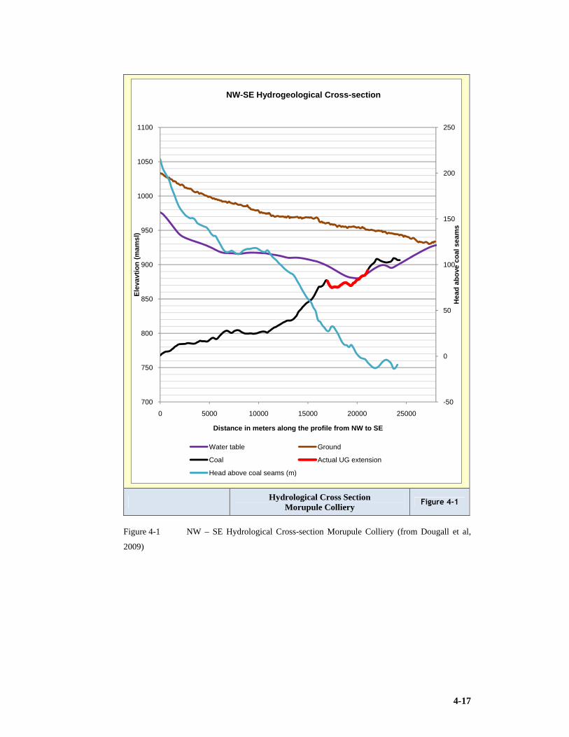
4-17
Hydrological Cross Section Morupule Colliery
Figure 4-1
Figure 4-1 NW – SE Hydrological Cross-section Morupule Colliery (from Dougall et al,
2009)
-50
0
50
100
150
200
250
700
750
800
850
900
950
1000
1050
1100
0 5000 10000 15000 20000 25000
Hea
d a
bo
ve c
oal
sea
ms
Ele
vavt
ion
(m
amsl
)
Distance in meters along the profile from NW to SE
NW-SE Hydrogeological Cross-section
Water table Ground
Coal Actual UG extension
Head above coal seams (m)

4-18
Watertable Contours & Groundwater Flow Direction
Figure 4-2
Figure 4-2 Water table contours and groundwater flow direction (from Dougall et al, 2009)

4-19
Figures 4-1 and 4-2 detail significant hydrology detail for Morupule colliery.
4.10 Conclusions
1) In a region such as southern Africa where water resources need to be protected,
groundwater needs to be considered carefully when planning new mining
operations or increasing the percentage extraction.
2) Increased extraction leads to fracturing of overlying strata and in the right
circumstances lead to increased water inflow into the mine.
3) Water may become contaminated by contact with sulphides (AMD), therefore the
dispersal of water during the life of the mine and the effects following mine
closure need to be considered carefully before mining commences.
4) Where the surrounding water table has been contaminated with nitrates and
bacteria (E Coli) the resulting drawdown as a consequence of mining activities
could result in further pollution of the water table that was previously more wide
spread or remote and currently polluted.
Replenishment of dry or polluted wells will always be a challenge and could be costly to
the mine operator. It may require sourcing by purchase from the utility (water board).

5-1
5 ROCK ENGINEERING
5.1 Defining Rock Engineering
Work in Rock Engineering has been described by notable authors and practitioners
namely Brady and Brown (1993), Franklin and Dusseault (1989), Jager and Ryder (2001)
and Budavari (1985). The most current and adequate coverage of the high extraction
environment is work by Van der Merwe & Madden (2002).
Van der Merwe and Madden have recorded that “the science of rock mechanics is
relatively new as a separate branch of the study of mechanics. While it has always
existed, it has only been formally recognised since the 1960’s. It has been defined as the
study of the reaction of the rock mass to changes made therein by man. While rock
mechanics is a field of study, or a science, the application thereof is rock engineering”
(Van der Merwe & Madden, 2002). This is supported by Jager and Ryder (2001).With
regard to the similarity of coal mining across continents van der Merwe states, “Coal
mining in South Africa, Australia and North America is sufficiently similar with regard to
physical parameters and mining equipment to be classified jointly” (Van der Merwe &
Madden, 2002).
5.2 Friction Affects the Efficiency of Roof Support
It is apparent that in the mining environment, “friction plays a major role in the efficiency
of roof support anchors, be it resin or mechanical anchors, and in the sliding of roof
layers over one another in a laminated roof” as confirmed by van der Merwe & Madden,
(2002). Van der Merwe & Madden, (2002) defines friction as “the force that resists
sliding. Its magnitude depends on only three basic parameters, namely: the magnitude of
normal force acting on the sliding plane, the cohesion acting on the plane and the friction
coefficient between the two surfaces” (van der Merwe & Madden, 2002). The magnitude
of the shear stress required to overcome friction can be calculated by the Coulomb
equation (Equation 5.1) from van der Merwe & Madden (2002):
Equation 5-1 Coulomb Equation
Τ = C + σn tan φ

5-2
Where
Τ= Shear stress in kPa
tan φ = friction coefficient
φ = friction angle
σn = normal stress in kPa
C = Cohesion between objects in kN.
“In the case of roof layers sliding over one another, the resistance to sliding can be
increased by increasing the normal force on the interfaces. In practice this is achieved by
pre-stressing roof bolts” (Van der Merwe & Madden, 2002).
5.3 Stratified Rock Layers Behave Like Beams
Van der Merwe and Madden (2002) also declares that “the coal mining environment is
characterised by stratified or layered geological units. These behave like plates, and the
behaviour of plates can be simplified to that of beams under most circumstances. When
the length of a plate is significantly greater than its width, its behaviour approaches that
of a beam. There are several different types of beams and consequently only two types of
beams will be discussed, namely clamped beams and cantilevers. An unjointed roof acts
like a clamped beam in its simplest form. The most important visual, or measurable,
characteristic of a clamped beam is that it sags. The amount of sag is greatest in the centre
and it approaches zero at the edges. The maximum stresses induced in the beam occur at
the edges. At the bottom centre of the beam the stresses are tensile and they are
compressive at the top. Rock is weaker in tension than in compression. In the case of a
mine roof, part of the beam is not visible and therefore the onset of tensile failure may not
be seen” (Van der Merwe & Madden, 2002). The magnitude of the maximum tensile
stress is given by Equation 5.2:
Equation 5-2 Magnitude of the maximum tensile stress
Where:
σ = Maximum tensile stress in kPa
λ = unit weight of beam (kg)
σ =λL2/2t

5-3
t = thickness of beam (m)
L = length of unsupported span (m).
Van der Merwe and Madden (2002) states that, “when the continuity of a clamped beam
is broken, for instance by a joint in the roof, the magnitudes of sag and stress are no
longer valid. The free end of the beam is now stress free, but the stresses at the clamped
edge are still there. The magnitude of the tensile stress increases six-fold. The practical
implication of this is that the mere presence of a joint in the roof immediately results in
six times the tensile stress, again at a point at the top of the beam that is not visible” (Van
der Merwe & Madden, 2002). Figure 5.1 depicts a cantilever which is in reality a beam
with one side unclamped. Note the tensile stress at the top and the compressive stress at
the bottom of the beam or cantilever.
Cantilever Beam Figure 5-1
Figure 5-1 A cantilever beam (from van der Merwe & Madden, 2002)
5.4 Underground Stress
Mining does not create stress it merely re-arranges the stresses that were always there and
is referred to as induced stress. “If the extent of mining is limited to bord and pillar
mining, the stress changes are also minimised. If high extraction mining is done, we
experience the full extent of stress re-distribution” (Van der Merwe & Madden, 2002).
Van der Merwe and Madden (2002) defines Rock Mechanics through this explanation
“mining tends to unbalance the natural forces that have been in balance for geological
time and nature always tends toward balance, and, when we create disturbances, nature
will react by striving to reach a new balance. The study of this reaction is called the
science of rock mechanics” (Van der Merwe & Madden, 2002).

5-4
It is known that before mining commences, the rock environment is subjected to virgin
stress. The vertical component of stress is caused by the weight of the overlying rock. The
horizontal component, however, has a largely uncertain origin and cannot be calculated as
readily as the vertical component according to van der Merwe & Madden, (2002). It is
often expressed as the k-ratio. Van der Merwe and Madden (2002) is quoted “At depths
in excess of say 1000m, the k-ratio has been found by measurement to be in the region of
0.5 to 1.0. At shallow depth, the ratio is much higher, ranging from around 1.0 to as high
as 6.0, while in isolated areas it has been found to be as high as 12.0. It is usually about
2.0. The use of the concept of the k-ratio at shallow depth is questionable and often
misleading, because in general the stress magnitudes are low. Often a high k ratio does
not necessarily imply that the absolute stress levels are high enough to cause undue
problems” (Van der Merwe & Madden, 2002). Research by Coaltech was commissioned
during 2010 on the horizontal stress regime in large expansive collieries and well
exploited coalfields to enable better understanding.
Van der Merwe reports that “the horizontal component of stress at shallow depth is
greater than that which can be explained by the Poisson effect (i.e. the rock under vertical
compression attempts to expand laterally and because it is confined, stresses are
generated). There are several theories to explain the origin of this horizontal stress. A
popular theory in the USA and Australia is that the stresses are generated by plate
tectonics. Therefore, the stresses are generated by the continental plates pushing against
one another. In South Africa, this theory is not widely accepted, as the coal mining region
is remote from any known plate contact points” (Van der Merwe & Madden, 2002).
5.4.1 Properties of some coal measure rocks
Coal measures are made up of rocks that are mainly sedimentary in nature. The Table 5.1
highlights some of these properties.
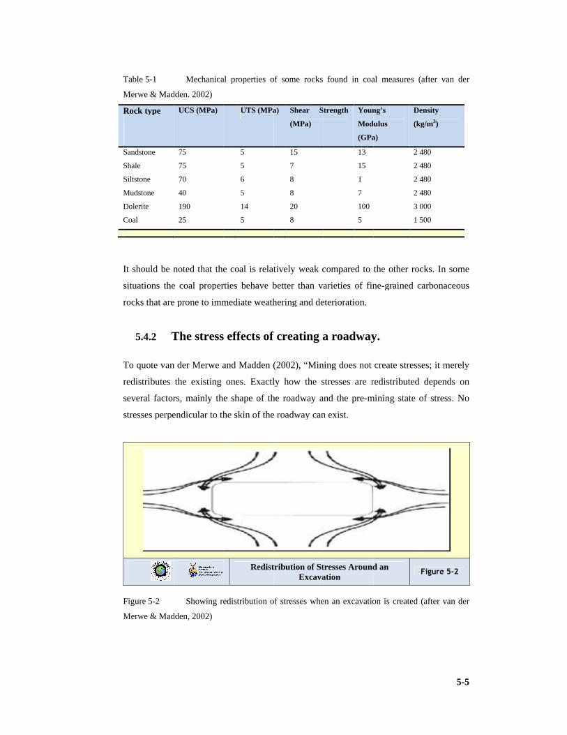
Table
Merwe & Madden. 2002)
Rock type
Sandstone
Shale
Siltstone
Mudstone
Dolerite
Coal
It should be noted that the coal is relatively weak compared to the other rocks. In some
situations the coal properties behave better than varieties of fine
rocks that are prone to
To quote van der Merwe and Madden (2002), “
redistributes the existing ones. Exactly how the stresses are redistributed depends on
several factors, mainly the shape of the roadway and the pre
stresses perpendicular to the skin of the roadway can exist
Figure
Merwe & Madden, 2002)
Table 5-1
Merwe & Madden. 2002)
Rock type
Sandstone
Shale
Siltstone
Mudstone
Dolerite
Coal
It should be noted that the coal is relatively weak compared to the other rocks. In some
situations the coal properties behave better than varieties of fine
rocks that are prone to
5.4.2 The
To quote van der Merwe and Madden (2002), “
redistributes the existing ones. Exactly how the stresses are redistributed depends on
several factors, mainly the shape of the roadway and the pre
stresses perpendicular to the skin of the roadway can exist
Figure 5-2
Merwe & Madden, 2002)
Mechanical properties of some rocks found in
Merwe & Madden. 2002)
UCS (MPa)
75
75
70
40
190
25
It should be noted that the coal is relatively weak compared to the other rocks. In some
situations the coal properties behave better than varieties of fine
rocks that are prone to immediate weathering and deterioration.
The stress
To quote van der Merwe and Madden (2002), “
redistributes the existing ones. Exactly how the stresses are redistributed depends on
several factors, mainly the shape of the roadway and the pre
stresses perpendicular to the skin of the roadway can exist
Showing redistribution of stresses when an excavation is created (
Merwe & Madden, 2002)
Mechanical properties of some rocks found in
UTS (MPa)
5
5
6
5
14
5
It should be noted that the coal is relatively weak compared to the other rocks. In some
situations the coal properties behave better than varieties of fine
immediate weathering and deterioration.
stress effects of creating a roadway
To quote van der Merwe and Madden (2002), “
redistributes the existing ones. Exactly how the stresses are redistributed depends on
several factors, mainly the shape of the roadway and the pre
stresses perpendicular to the skin of the roadway can exist
Redistribution of Stresses Around an
Showing redistribution of stresses when an excavation is created (
Mechanical properties of some rocks found in
UTS (MPa) Shear Strength
(MPa)
15
7
8
8
20
8
It should be noted that the coal is relatively weak compared to the other rocks. In some
situations the coal properties behave better than varieties of fine
immediate weathering and deterioration.
effects of creating a roadway
To quote van der Merwe and Madden (2002), “Mining does not create stresses; it merely
redistributes the existing ones. Exactly how the stresses are redistributed depends on
several factors, mainly the shape of the roadway and the pre
stresses perpendicular to the skin of the roadway can exist
Redistribution of Stresses Around an Excavation
Showing redistribution of stresses when an excavation is created (
Mechanical properties of some rocks found in coal measures (after van der
Shear Strength Young’s
Modulus
(GPa)
13
15
1
7
100
5
It should be noted that the coal is relatively weak compared to the other rocks. In some
situations the coal properties behave better than varieties of fine
immediate weathering and deterioration.
effects of creating a roadway
Mining does not create stresses; it merely
redistributes the existing ones. Exactly how the stresses are redistributed depends on
several factors, mainly the shape of the roadway and the pre-mining state of stress
stresses perpendicular to the skin of the roadway can exist.
Redistribution of Stresses Around an Excavation
Showing redistribution of stresses when an excavation is created (
coal measures (after van der
Young’s
Modulus
(GPa)
Density
(kg/m
2 480
2 480
2 480
2 480
3 000
1 500
It should be noted that the coal is relatively weak compared to the other rocks. In some
situations the coal properties behave better than varieties of fine-grained carbonaceous
effects of creating a roadway.
Mining does not create stresses; it merely
redistributes the existing ones. Exactly how the stresses are redistributed depends on
mining state of stress
Redistribution of Stresses Around an Figure 5
Showing redistribution of stresses when an excavation is created (
5-5
coal measures (after van der
Density
(kg/m3)
2 480
2 480
2 480
2 480
3 000
1 500
It should be noted that the coal is relatively weak compared to the other rocks. In some
grained carbonaceous
Mining does not create stresses; it merely
redistributes the existing ones. Exactly how the stresses are redistributed depends on
mining state of stress. No
Figure 5-2
Showing redistribution of stresses when an excavation is created (after van der

5-6
There is then a concentration of stresses around the edges of the roadway” (Van der
Merwe & Madden, 2002). Figure 5.2 shows the redistribution of stresses around the
excavation, the induced stress concentration being greater than the virgin stress. To quote
Van der Merwe and Madden (2002), “All the stresses acting perpendicular to the skin are
reduced to zero while all the ones parallel to the skin are magnified. This means that in
the roof, the horizontal stress is magnified while the vertical stress is zero. In the rib sides,
the horizontal stress becomes zero and the vertical stress is magnified” (Van der Merwe
& Madden, 2002).
Van der Merwe and Madden (2002) also states that “In a homogeneous rock the severity
of the stress concentration in the corners depends on two factors, namely the sharpness of
the corner and the orientation of the principal stresses. The more rounded, the corner, the
less severe the stress concentration is” (Van der Merwe & Madden, 2002).
Stress Flux Concentration in Corners of Roadway
Figure 5-3
Figure 5-3 Stress concentration in corners of roadway (from van der Merwe & Madden,
2002)
Figure 5.3 shows the concentration of stress flux at the corners of the excavation and
Figure 5.4 is a photograph of guttering on the left hand side that has been supported. The
guttering is caused by stress failure due to increased horizontal stress. The failure occurs
at the top corner against the abutment which is tri-axially confined.

5-7
Guttering Due to Horizontal Stress Figure 5-4
Figure 5-4 Guttering due to horizontal stress (from van der Merwe & Madden, 2002)
Controllable parameters
Van der Merwe and Madden (2002) has clearly defined the most important parameters as
“the rock quality, state of stress and the presence of discontinuities are given and cannot
be changed. The three main controllable parameters are road width, time of support
installation (linked to the cut-out distance) and the characteristics of the support system”
(Van der Merwe & Madden, 2002). Van der Merwe and Madden’s explanations of these
factors follow:
Road width. “The amount of roof sag is proportional to the fourth power of road width.
This means that if the road width is doubled, the amount of sag will increase sixteen
times. It is well known that decreasing the road width is the first step to be taken when
bad roof is encountered, and this explains why. It also explains why road width control is
essential in high extraction mining, why intersections are prone to roof falls and why
uncontrolled cutting away of the corners at intersections is dangerous. In an intersection,
the diagonal distance is 1.4 times the road width. This means that the roof sag is
potentially 3.8 times as great. If only 1m is cut off one corner of a pillar, the 3.8 factor
increases to 5.8. To make matters worse, if a holing is made into an unsupported
intersection, the increase in width is a sudden event and the roof experiences the sudden
increase in sag as a shock. Road width control is vital for another very important reason.
In several situations the supports that are installed are only intended to suspend the weak
material underneath the more competent layers above (like sandstone), and not to support

5-8
the main sandstone beam itself. In the absence of special supports like long anchors, the
stability of the sandstone beam is controlled by one parameter, and one only, and that is
road width” (Van der Merwe & Madden, 2002).
Time. “At present, the effects of time on roof behaviour cannot be quantified
mathematically. From limited work done in laminated shale/sandstone type roofs and
thick mudstone units, it appears that the majority of the deflections occur soon after the
roof has been exposed and that it is controlled to a larger extent by face advance than by
time. From the stage that the face advances away from the last line of bolts is equal to the
road width, the rate of deflection decreases rapidly with further advance. This means that
especially in adverse conditions, bolts should be installed very close to the face if they are
to have the maximum effect. Note that this means that if it is necessary to increase the
cut-out distance (the distance the CM cuts before withdrawing to support), it can be done
by limiting the road width, provided that the ventilation requirements are met. A time
may be reached when it is too late to support. The cracks are there, just waiting for the
slightest disturbance. Sometimes the late installation of support is the disturbing force. If
the roof survives that, the second possible trigger is the disturbance caused by high
extraction mining. Sometimes the causes of roof falls in stooping cannot be established.
Maybe there are no joints, no slips, and the bolts are well installed, yet there was a fall.
Often what is called a ‘danger inherent to mining’ is a man-made danger, created months
before by not having installed support soon enough during development. Roof support is
not a separate operation in mining. It is an integral part of the act of mining. If the roof
bolter breaks down, mining should cease. An excavation that cannot be supported must
not be made. This should be borne in mind at the end of the shift, and before weekends”
(Van der Merwe & Madden, 2002).
Support provision. “The support provision loop begins with the identification of the
most likely mechanism of roof falls in any area. The second step is to design a suitable
support system; taking cognisance of the geological and stress conditions, the equipment
that is available to install the supports, the support materials that are available and the
level of training of the work force. If any new element is to be introduced into the chain,
it has to be accompanied by proper training. It is pertinent to mention the basic design
procedure at this stage. The first step is to determine the load on the system, including
gravity and, if present, the effects of higher than normal horizontal stress. Next, the
system has to be able to withstand the imposed loads. This is achieved by balancing the
length, diameter and the spacing of the tendons. It is important to first fix the spacing of
the tendons, and then the lengths. The reason for this is that a load calculation on its own

5-9
may result in a system that is able to withstand the loads imposed on it from a force
balance point of view, but, it will not necessarily create a stable beam. Neither will it be
able to prevent the small but potentially lethal falls between bolts. In cases where high
horizontal stress is the cause of roof instability, or where an artificial beam is to be
created, it is essential to concentrate on the stiffness of the support system. The third step
is to install the supports. It is vital that a proper procedure for this be laid down and that
the necessary discipline is maintained.
The fourth step is monitoring, which consists of four main elements. The applicability of
the system as designed must be monitored on an ongoing basis, which includes taking
cognisance of changes in the geological conditions. The quality of the installations has to
be monitored on a daily basis—this is an important function of supervisors. The quality of
the support materials has to be checked to ensure that it conforms to the requirements of
the designed system. Lastly, the integrity of the support over time has to be checked,
bearing in mind that steel corrodes” (Van der Merwe & Madden, 2002).
5.5 Geotechnical Classification
The mining engineer must appreciate the following geotechnical concepts, as reported by
Van der Merwe & Madden (2002), if he or she is to design best practice mining systems.
These classification systems are supported by Hoek and Brey (1995), Brady and Brown,
(1993), and Budavari, (1985).
5.5.1 Rock mass classification
Jager and Ryder (2001) identified and so does Van der Merwe and Madden (2002) that
rock technologists tend to use the following concepts to classify rock quality:
Rock Quality Designation (RQD)
RQD gives an estimate of the blocky nature of the strata. Defined as the, “length of core
in excess of 100mm (0.1m) divided by the total length of a particular strata unit expressed
as a percentage” (Van der Merwe and Madden, 2002).
Durability and swell tests
“Slake durability and swell tests provide an estimate into the likely impact of clay
minerals and water on the behaviour of the strata and are particularly important as
indicators of floor conditions” to quote Van der Merwe and Madden (2002).
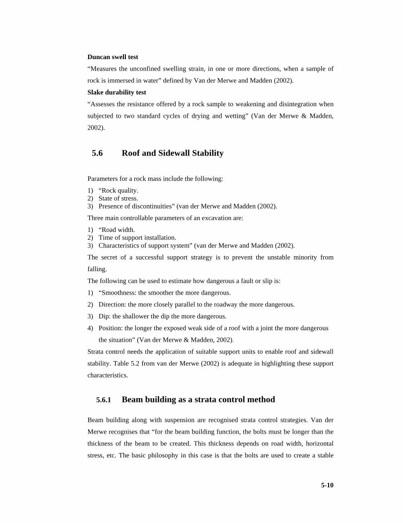
5-10
Duncan swell test
“Measures the unconfined swelling strain, in one or more directions, when a sample of
rock is immersed in water” defined by Van der Merwe and Madden (2002).
Slake durability test
“Assesses the resistance offered by a rock sample to weakening and disintegration when
subjected to two standard cycles of drying and wetting” (Van der Merwe & Madden,
2002).
5.6 Roof and Sidewall Stability
Parameters for a rock mass include the following:
1) “Rock quality. 2) State of stress. 3) Presence of discontinuities” (van der Merwe and Madden (2002).
Three main controllable parameters of an excavation are:
1) “Road width. 2) Time of support installation. 3) Characteristics of support system” (van der Merwe and Madden (2002).
The secret of a successful support strategy is to prevent the unstable minority from
falling.
The following can be used to estimate how dangerous a fault or slip is:
1) “Smoothness: the smoother the more dangerous.
2) Direction: the more closely parallel to the roadway the more dangerous.
3) Dip: the shallower the dip the more dangerous.
4) Position: the longer the exposed weak side of a roof with a joint the more dangerous
the situation” (Van der Merwe & Madden, 2002).
Strata control needs the application of suitable support units to enable roof and sidewall
stability. Table 5.2 from van der Merwe (2002) is adequate in highlighting these support
characteristics.
5.6.1 Beam building as a strata control method
Beam building along with suspension are recognised strata control strategies. Van der
Merwe recognises that “for the beam building function, the bolts must be longer than the
thickness of the beam to be created. This thickness depends on road width, horizontal
stress, etc. The basic philosophy in this case is that the bolts are used to create a stable

5-11
beam by preventing lateral sliding of the laminae. This can only be achieved if the bolts
are installed before any bed separation occurs. Obviously, full column resin is required
for this function. In theory, the same can be achieved by installing pretensioned
mechanical or resin point anchors, but because these lose tension, the beam building
function is lost very soon” (Van der Merwe & Madden, 2002).
5.6.2 Suspension as a strata control method
Roof support by suspension is done in the case where the roof consists of a layer of weak,
or laminated, material overlain by a self-supporting layer like thick sandstone. Van der
Merwe states that “the roof is then stabilised by suspending the weak material onto the
stronger layer. With resin bolts, the longer the resin portions in the hole, the stronger the
anchor. The bolt length must thus be greater than the thickness of the laminations, with
enough left over to have a strong enough anchor to suspend the laminations. The required
strength of the anchor depends on the spacing of the bolts and the thickness of the
laminated layer.
Suspension Support of Laminated Beam Anchoring Weaker Layers in Sandstone
Figure 5-5
Figure 5-5 Suspension of laminated beam (from van der Merwe & Madden, 2002)
The thicker the laminated layer and the greater the spacing, the longer the bolts must be”
(Van der Merwe & Madden, 2002). Figure 5.5 depicts a laminated beam being suspended
by the tendons.

5-12
Suspension is based on the principle that each tendon or bolt carries its share of the total
tributary load of the immediate roof. Support load per tendon is critical and must not
exceed the carrying strength of a tendon.
5.6.3 Incorrect bolt installations
How do operators ensure that there is correct bolt installation? Firstly, adherence to the
required pattern can be measured; secondly, the quality of the anchor can only be
deduced; thirdly, pull tests can be done to test for major deviations on full column
installations, but not to determine the full anchor resistance of the bolt. Van der Merwe
provides the reason for this is “that a pull test is performed on the protruding end of the
bolt and consequently the load that is obtained in the test is the full frictional resistance
over the entire length of the bolt. Even if the resin bond is inferior, it is possible for the
full load to exceed the breaking strength of the steel. For instance, the unit frictional
resistance between the resin and the rock is in the range of 2,000kPa to 3,000kPa for most
rock types. If something went wrong during the installation, that resistance will be
reduced. If it is reduced to 1,500kPa, approximately half of the required resistance, then
the total load in a pull out test for a 1.8m long bolt in a 28mm hole will be 237kN, which
is in excess of the strength of most 20mm bolts. Thus, even with only 50% of the required
resistance, the bolt could pass during the test. Moreover, it will seldom be possible in
practice to obtain loads equal to the steel material strength, as the pull test will invariably
be done on the threads, which will fail at lower loads in most cases” (Van der Merwe &
Madden, 2002).
“The most common errors during installation are incorrect hole lengths and incorrect
resin mixing. The materials are also sometimes defective; washer plates may be too thin
and crimps on the crimp nuts may be too weak or too strong. Torque settings on roof
bolters may be too high or too low and sometimes the spinning adapters are worn” (Van
der Merwe & Madden, 2002) . The visual appearance of a correctly installed bolt is
shown in Figure 5.7 and installation errors in Figure 5.6.

5-13
Bolt Error Identification Figure 5-6
Figure 5-6 Visual error identification on roofbolt installations (from van der Merwe &
Madden, 2002)
Correctly Installed Bolts Figure 5-7
Figure 5-7 Correctly installed bolts (from van der Merwe & Madden, 2002)

5-14
5.6.4 Breaker lines
The purpose of breaker line supports in pillar extraction is to prevent the roof collapsing
from the goaf side into roadways. The ideal breaker line forms a sharp edge across the
roadway, causing the roof to break off on the goaf side, hence the name. To perform this
function, a breaker line must be stiff and strong enough, and the individual elements, be it
mine poles or bolts, must be spaced close enough together. “There are three basic types of
breaker lines: mine poles, roof bolts and mobile hydraulic prop systems” (Van der Merwe
& Madden, 2002).
Mine pole breaker lines
“A common type of arrangement for a mine pole breaker line is shown in Figure 5.8. It
usually consists of a double line of mine poles spaced 1m apart supplemented by a finger
line running diagonally across the roadway. Breaker lines and finger lines have to be cut
the right length and must be firmly wedged against the roof. It is customary for breaker
lines to be installed a short distance from the pillar edges, to prevent the mine poles being
knocked over by rocks sliding out of the goaf. The disadvantages of mine pole breaker
lines are that they are labour intensive to transport and install, cumbersome to install
properly (especially at high mining heights) and require people to work at the goaf edge
during their installation.
Table 5-2 Support element characteristics (from Van der Merwe & Madden, 2002)
System Active
/Pas
Stiff/
Soft
Corrosion
Resist
Ease
of Instal
Pull
out
resist
Use Avoid Relative
Cost
Mechanic
al Anchor
Active Soft Medium Good Medium Short Term
Unlaminated
roof
Medium to
light load
Longterm
Laminated
roof
Burnt coal
Ribside
Cheap
Resin
Point
Anchor
Active Soft Medium Medium,
requires
training
Very
good
Short Term
Unlaminated
roof
Medium to
heavy load
Longterm
Laminated
roof
Burnt coal
Ribside
Cheap
Full
Column
Resin
(Single
Passive Stiff Good Medium,
requires
training
Very
good
Long term
Laminated
roof
Heavy load
Burnt coal
Ribside
Expen-
sive

5-15
System Active
/Pas
Stiff/
Soft
Corrosion
Resist
Ease
of Instal
Pull
out
resist
Use Avoid Relative
Cost
Type) Thick weak
roof
Close to
face
Full
Column
Resin
(Slow/Fa
st
Combo)
Active Stiff Good Medium,
requires
training
Very
good
Long term
Laminated
roof
Heavy load
Beam
building
Thick weak
roof
High
horizontal
stress
Burnt coal
Ribside
Expen-
sive
Split set Passive Stiffish Poor Good Poor Burnt coal
ribsides
Wire mesh
fill in
Thin
laminated
layers
Short term
Light load
Long term
Heavy load
Thick layers
Expen-
sive
Trusses Active Stiffish
(cable
trusses
soft)
Good Cumbers
ome
Very
good
Jointed
areas
Major joints
& faults
Very
expen-
sive
W straps Stiff Medium Cumbers
ome
Jointed
areas
Friable roof
Beam
building
High
horizontal
stress
Expen-
sive
Wooden
dowels
Passive Stiff
but
weak
Excellent Easy Poor L/W faces
Ribsides in
stooping
Roof Cheap
Fibre
glass
dowels
Passive Stiff Excellent Easy Good L/W faces
Ribsides in
stooping
Expen-
sive
Wire
mesh &
shotcrete
Passive Stiff if
well
installe
Good Cumbers
ome
Burnt coal
Jointed
areas
Expen-
sive

5-16
System Active
/Pas
Stiff/
Soft
Corrosion
Resist
Ease
of Instal
Pull
out
resist
Use Avoid Relative
Cost
d Friable roof
Long term
densely
populated
areas
Chemical
injection
Passive Stiff Excellent Cumbers
ome
L/W
facebreak
Presupport
in very
weak
jointed
conditions
Very
expen-
sive
Minepole Breakerlines Figure 5-8
Figure 5-8 Mine pole breaker lines (from van der Merwe & Madden, 2002)
Where mining heights are in excess of 3.5m, it even becomes difficult to get mine poles
of the right length. On the positive side, they have been shown to be effective over
several decades of mining and have the advantage of warning of impeding roof failure by
making cracking noises and showing obvious signs of increased load. To the experienced
miner, ‘timber talks’, implying that it gives an audible warning” (Van der Merwe &
Madden, 2002).
Roof bolt breaker lines
“Roof bolt breaker lines perform the same function as timber breaker lines. They usually
consist of a double line of full column resin grouted bolts across the roadway, spaced at

5-17
1m. Roof bolt breaker lines come into their own in relatively strong strata, being
particularly successful in areas where a strong sandstone beam overlies laminated
material. They are often the most economical safe solution at high mining heights. It is
important for the roof bolts to be long enough to penetrate into the sandstone beam. They
must be full column resin bonded for stiffness, and should ideally be installed during
development, before the stooping- induced movements start taking place. The major
disadvantage of roof bolt breaker lines is that they give less warning of changing
conditions. This problem is usually overcome by installing a single timber prop in the
centre of the roadway, the so-called ‘policeman stick’. The advantages of roof bolt
breaker lines (shown in plan in Figure 5.9) are that they are easier to install, can be
installed during development (which is safer than working at the goaf edge), are not
affected by mining height and require less labour. If pre-installed, their installation does
not hamper the process of pillar extraction” (Van der Merwe & Madden, 2002).
Roofbolt Breakerlines Figure 5-9
Figure 5-9 Roof bolt breaker lines (after van der Merwe & Madden, 2002)
Mobile breaker lines
“A mobile breaker line consists of a set of four hydraulic props in a frame. It resembles a
longwall shield with a flat steel roof, mounted on cat tracks. The units are remote
controlled, and are used in pairs, parked side by side in the roadway.
Being mobile, they are moved forward after each cut into a pillar, following the
continuous miner. The advantages of mobile breaker lines are that the loads they generate
can be adjusted to suit specific roof conditions; they are always close to the continuous
miner, safe to operate and low on labour requirements. The disadvantages are that they
require a relatively obstruction-free floor, high capital outlay and that their use increases

5-18
the number of units in a section which require maintenance and they may break down.
The varying load cycles they impart on the roof has been seen to cause, especially jointed
roof, to fall and in instances where they are not moved forward on time, may themselves
be covered by goaf collapse. Although they were developed in South Africa for the
Middelbult Colliery, they are not used locally, mainly due to the high capital cost.” (Van
der Merwe & Madden, 2002). Figure 5.10 gives a schematic of the positions of
mechanised mobile breaker lines.
Mobile Mechanised Breakerlines Figure 5-10
Figure 5-10 Mobile breaker lines (after van der Merwe & Madden, 2002)
5.7 Pillar Design
Initial work by Salamon (Salamon and Munro including Salamon and Canubulat) set the
process. Van der Merwe and Madden (2002) stipulate that “Coal pillar design is of
primary importance for the safe, economic extraction of a valuable national resource. It is
often determined by the strategy of the mining company or the philosophy of the mine
manager. The basic choice is whether to opt for maximum extraction on the advance,
thereby leaving permanent coal pillars, or maximum overall extraction of the coal
reserves, where larger pillars are deliberately formed with the intention of extracting them
at a later date. As a mine nears the end of its life there are economic and social pressures
to extend the life of the mine for as long as is technically and economically feasible.
Consequently, areas only designed for primary extraction and showing no signs of stress

5-19
or deterioration are often re-appraised to determine if they are suitable for some form of
secondary extraction” (Van der Merwe & Madden, 2002).
For a bankable feasibility study, a pillar design based on numerical modelling is the
recommended way to get away from ‘design rules’ that were developed before cheap
computing power became available. These rules have served the industry well, but
changed two elements of design at the same time, namely production and barrier pillars,
and the relationship between the two introduces conservatism into the design. Hence a
new technique raises its head in numerical modelling (Dougall et al, 2009).
The well used formulae sourced from work by Salamon and subsequent work by Van der
Merwe & Madden (2002) give solutions for:
1) Load for squat pillar in terms of: depth to floor (H); pillar centre (C); pillar width (w).
2) Strength for a squat pillar (S).
3) The load on a pillar if a dolerite sill is present in terms of: depth to floor (H);
thickness of sill (T); pillar centre (C); pillar width (w).
4) The load on a rectangular pillar (L).
5) The pillar strength in terms of pillar width (w) and pillar height (h).
6) The effective width of a rectangular pillar in terms of: pillar area (A); pillar centre.
7) The safety factor in terms of: pillar width (w); depth to floor (H); pillar centre (C);
pillar height (h).
8) The equivalent width for a parallelogram pillar.
9) The pillar load for parallelogram pillars.
5.8 Rock Mechanics of Pillar Extraction
We need to have an understanding of the caving propensity of our strata. When sills are
present they act as beams and influence the stress regime significantly. The design
engineer will be challenged with the question of optimal panel width to enable effective
caving where this is required and control of abutment stresses.
It is necessary to determine critical panel widths in competent and incompetent strata. It is
also necessary to consider the orientation or direction when extracting pillars. The advice
offered by van der Merwe (2002) is effective and follows.

5-20
5.8.1 Critical panel width
“Critical span is the width at which goafing can initiate. The formula for the calculation
of critical panel span is:
Incompetent strata:
Equation 5-3 Critical mining span incompetent strata
Where
Lc= critical mining span (m)
H= depth to floor (m)
Ф = goaf angle which in absence of site specific data can be taken as 15º.
Very strong strata:
Equation 5-4 Critical mining span strong strata
Where
Ks= horizontal to vertical virgin stress (kPa)
H= mining depth (m)
D= depth of dolerite base (m)
T= thickness of dolerite (m)
Ф= goaf angle (measured off vertical)”
(Van der Merwe & Madden, 2002)
5.8.2 Extraction safety factor (ESF)
When creating fenders during extraction the design should account for the specific safety
factors of the remnants. The formula for calculating the extraction safety factors is (Van
der Merwe and Madden, 2002): Pillar Strength / Pillar Load
Lc= 2T√(ks + β/D) +2(H-D)tanФ
Lc= 2HtanФ

5-21
5.8.3 Important points relative to pillar extraction
To quote van der Merwe, the important points relative to pillar extraction are:
1) “When a pillar is split, the stress on the fenders increases because the load bearing
area is smaller.
2) Also, the stiffness of the fenders is less than that of the pillar prior to being split,
because the w/h ratio is less.
3) Therefore, the probability of the fender failing in the first place, and failing violently
in the second place, is higher.
4) The system stiffness depends on the number of pillars in a panel—the wider the
panel, the softer the system and the greater the possibility of violent failure. System
stiffness is reduced by non-continuity of the overburden—faults and dykes. Reduce
the system stiffness and increase the probability of violent failure” (Van der Merwe
& Madden, 2002).
Figure 5.11 shows that the next panel should be stooped in a direction which
places the goafs together and mining direction is away from the goaf.
Correct Stooping Direction Away From Old Goaf
Figure 5-11
Figure 5-11 Stooping direction away from old goaf (Van der Merwe & Madden, 2002)

5-22
Remnant Safety Factors Figure 5-12
Figure 5-12 Approximate safety factor of snooks during phases of pillar extraction (Van der
Merwe & Madden, 2002)
Figure 5.12 highlights the safety factors of the remnant snooks and fenders. The miner
should always be cognitively aware of these and the consequent risks.
Ideal Goaf Position up to Last Line of Snooks
Figure 5-13
Figure 5-13 Ideal goaf position with only one line of snooks (Van der Merwe & Madden,
2002)
Figure 5.13 displays the relative position of goaf and the last line of snooks all others
having crushed in the ideal situation.

5-23
Pillars must be Split at Right Angles to the Goaf
Figure 5-14
Figure 5-14 Pillars should always be split at right angles to the goaf (Van der Merwe &
Madden, 2002)
Checkerboard Stooping Figure 5-15
Figure 5-15 Checkerboard stooping (Van der Merwe & Madden, 2002)

5-24
Correct Stooping Direction at Right Angles to Long Axis of Pillar
Figure 5-16
Figure 5-16 Pillar splitting orientation (Van der Merwe & Madden, 2002)
Figure 5.14 shows the correct splitting direction of a pillar, Figure 5.15 depicts the
process of splitting with the chequerboard mining layout and Figure 5.16 illustrates that
the pillar should be split uniformly in one direction normally at right angles to the long
axis. Figure 5.15 depicts chequerboard stooping and Cut A in adjacent pillar is only taken
if conditions permit (Van Der Merwe & Madden, 2002).
5.9 Rock Mechanics of Wall Mining
The term ‘Longwalling’ means mechanical mining under the protection of shields. It thus
includes shortwalling, which is done with the same equipment but shorter face lengths.
Where a normal longwall face length is of the order of 200m, shortwall face lengths are in
the region of 50 to 100m. The rock mechanics of a shortwall is similar to that of a
longwall under the conditions of an overburden that has not failed through to surface.
Van der Merwe wrote “Longwalling in South Africa has met with mixed fortunes. Few
would doubt its benefits as a mining method under favourable conditions, less would
dispute its problems under unfavourable conditions. Conditions in this context refer more
to the macro geology than to micro ground conditions. Dykes are fairly common
occurrences in the South African coalfields and while there are a number of methods of
dealing with dykes in a longwall, they are expensive and they slow mining down. The
occasional dyke does not present a serious problem, but where the frequency increases, a

5-25
more flexible mining method is called for. As with pillar extraction, the rock mechanics
of longwalling in South Africa is dominated by the status (i.e. failed or intact) of the
dolerite sill or another strong layer where it is present. The sill is an igneous intrusion in
an otherwise sedimentary environment. The dolerite material is significantly stronger and
stiffer than the surrounding rock types. It often has the capability to bridge over panels of
common mining dimensions. Where this happens, significantly higher vertical loads
result than in cases where it has failed or where it is absent. These increased loads are
borne on the face, and inter-panel pillars, with a number of advantages and disadvantages
to mining. However, it is important to note that the loads do not result from the sill, but
from the fact that the sill prevents failure of the overburden. Therefore, the same effects
will result from any other geological or mining condition that prevents overburden
failure. Areas where at least one and often more of the overburden layers is a thick,
massive sandstone that can also bridge a panel and thereby cause the same high stress
levels that are associated with an intact dolerite sill. Failure of the sill has been studied
and there are methods whereby its status can be predicted. The same cannot be said for
the massive sandstone situation. The reason for this is that it is virtually impossible to
judge the condition (massive or jointed) of sandstone from vertical exploration boreholes,
while the presence of dolerite in a borehole is self evident. More often than not, one only
becomes aware of the presence of massive sandstone after mining has started in a
particular geotechnical area.” (Van der Merwe & Madden, 2002).
It should also be noted that the discussion to follow is restricted to the common South
African situation, where the depth of mining is 200m or less and face lengths are up to
300m.
5.9.1 Stress history of a longwall panel
Quoting van der Merwe whom analysed the stress history of a longwall panel, “as a
longwall face mines away from the start-up position, it is characterised by increasing
vertical stress. The stress continues to increase until either one of two things happens; the
overburden goafs completely, or, the face advance equals about 1.5 times the panel width.
When the overburden fails completely, there is a sudden decrease in stress—however, if
the overburden hangs up and the face advance is greater than the panel width, the stress
merely stabilises at the high level. At the initial stages of mining, falls occur in the back
area. These are minor falls, often referred to as the small goaf, extending some distance
into the roof depending on the roof geology. The bulk of the roof initially hangs up, and it
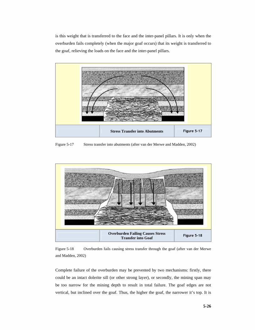
5-26
is this weight that is transferred to the face and the inter-panel pillars. It is only when the
overburden fails completely (when the major goaf occurs) that its weight is transferred to
the goaf, relieving the loads on the face and the inter-panel pillars.
Stress Transfer into Abutments Figure 5-17
Figure 5-17 Stress transfer into abutments (after van der Merwe and Madden, 2002)
Overburden Failing Causes Stress Transfer into Goaf
Figure 5-18
Figure 5-18 Overburden fails causing stress transfer through the goaf (after van der Merwe
and Madden, 2002)
Complete failure of the overburden may be prevented by two mechanisms: firstly, there
could be an intact dolerite sill (or other strong layer), or secondly, the mining span may
be too narrow for the mining depth to result in total failure. The goaf edges are not
vertical, but inclined over the goaf. Thus, the higher the goaf, the narrower it’s top. It is

5-27
possible for the span at the top of the goaf to become too narrow to allow failure of the
overburden layer immediately above it. This mechanism is the larger scale equivalent of a
roof fall that has ‘wedged out’. In South Africa, it is common for the major goaf to occur
at a face advance of approximately 150m to 200m where there is no dolerite, although
there are no hard and fast rules in this regard” (Van der Merwe & Madden, 2002). Figure
5.17 depicts stress transfer into pillars and Figure 5.18 displays the final transfer of the
stress through the goaf once caving has completed.
5.9.2 Inter-panel pillar design and longwall development
The view point of the reputable rock engineer van der Merwe is “In retreat longwalling,
inter-panel pillars are primarily provided to protect the gate roads while they also serve as
gas and water barriers. Inter-panel pillars are designed according to their function and the
loads expected to be imposed on them. There are several basic options, ranging from
solid pillars to chain pillars, to bearing pillars with crush pillars, to crush pillars only. If
pillars are to serve as gas and water barriers as well as to stabilize the gate roads, solid
pillars have been used, but they require double the amount of development as one panel’s
main gate cannot become the next panel’s tail gate. If successive panels are to progress up
dip so that water runs back into the old panels and gas does not present a problem, chain
pillars are usually used. The sizes of the pillars can be determined using two dimensional
numerical models for situations where the sill is not expected to fail. Once the load has
been calculated, the width can be determined to result in a safety factor of not less than
1.4 using an appropriate pillar strength formula. For final design, the load should be
determined by suitable pseudo three-dimensional numerical modelling. If the overburden
fails completely, the load situation is different.
The pillars then bear the load of the overburden directly above them plus the overhang,
which has been determined from subsidence studies to be approximately 15° off the
vertical, inclined over the goaf. There are a number of numerical codes that can be used
for this purpose. Even in cases where the overburden fails, the pillars at the beginning of
the panel will be subjected to high loads. It is common for those pillars to be longer than
the ones beyond the position where failure is expected, there has to be a balance between
reserve utilisation in the development phase and rate of advance” (Van der Merwe and
Madden, 2002). Figure 5.19 displays the use of larger pillars at the extraction road end
(installation road) of the wall panel.
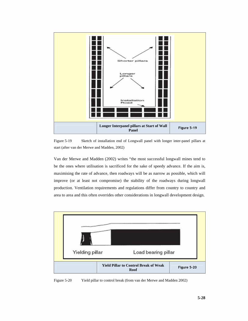
5-28
Longer Interpanel pillars at Start of Wall Panel
Figure 5-19
Figure 5-19 Sketch of installation end of Longwall panel with longer inter-panel pillars at
start (after van der Merwe and Madden, 2002)
Van der Merwe and Madden (2002) writes “the most successful longwall mines tend to
be the ones where utilisation is sacrificed for the sake of speedy advance. If the aim is,
maximising the rate of advance, then roadways will be as narrow as possible, which will
improve (or at least not compromise) the stability of the roadways during longwall
production. Ventilation requirements and regulations differ from country to country and
area to area and this often overrides other considerations in longwall development design.
Yield Pillar to Control Break of Weak Roof
Figure 5-20
Figure 5-20 Yield pillar to control break (from van der Merwe and Madden 2002)

5-29
In South Africa, three road development is common although there have been instances
of two-road development. For situations that are characterised by weak roof, yield pillars
have been designed in conjunction with larger bearing pillars (Figure 5.20). The
mechanism then is that the yield pillars allow roof deflection to take place, preventing
shear failure of the roof against the pillar edges. This is common practice in areas with
weak roof in the USA, although there seems to be a tendency for yielding pillars to be
implemented in areas with good roof as well” (Van der Merwe and Madden, 2002).
Where a number of adjacent longwall panels are mined, it is not uncommon for gate road
conditions to deteriorate progressively. This phenomenon is more evident in cases where
the overburden does not fail totally, as it is caused by the progressive load increase as the
mined area increases. This is similar to the mechanism of load increase in bord-and-pillar
mining, on a larger scale.
The first panel in a series is usually mined without undue problems. In the second panel,
tailgate problems begin to appear and by the time the third panel is mined, serious falls
are not uncommon in the tailgate. It is therefore sound practice to either increase the
inter-panel pillar widths for successive panels or to improve the roof support.
“It is counterproductive to save money on roof support in longwall development. In
longwalling, the tonnes (metric tons) produced per bolt installed is at least ten times that
of bord-and-pillar mining, and to jeopardise production from a R200M investment for the
sake of a R50 roof bolt (1,5m X 20mm with full column, spin to stall resin, Minerva
2007/12) is not sound practice” (Van der Merwe & Madden, 2002).
5.9.3 Secondary mining of inter-panel pillars
In order to improve coal reserve utilisation, the inter-panel pillars are sometimes either
partially or completely mined during the longwalling operation. Total removal is not
always a good option, as it usually requires artificial support to have been installed on the
main gate side of the previous panel to prevent the goaf flushing onto the face and
removal is also detrimental for ventilation. Partial mining of the inter-panel pillar has
often been carried out. One of the two chain pillars is mined completely and the other one
left intact. The splits are developed at 60° to prevent the entire length of the split being
exposed by the longwall at once. On fewer occasions, the one pillar in three-road
development has been mined completely, with the major portion of the remaining pillar.
In the latter example, blind cutting on the tailgate side required modification of the
equipment. The remaining pillar was designed to crush out for reasons of surface

5-30
subsidence control. The size of the pillar remnant was critical in this case, as it had to be
stable on the face, yet crush a short distance behind the face, before it could be
strengthened by the confining effect of the goaf on either side. Numerical modelling
coupled with observations in stooping sections on the same mine were extensively used in
the design procedure. In the end, a 6m wide crush pillar was left. The depth of mining
was 120m, the panel was 212m wide, the mining height was 3m and there was no dolerite
in the overburden.
Figure 5.21 shows the possible layout for extracting chain pillars between panels. A
photograph of a face break depicts the problematic environment obstructing production in
Figure 5.22.
Ash fill has been used between inter panel pillars, that was partially mined. Ash is placed
to stabilise inter-panel pillars. Polyurethane injection has been used to stabilise a standing
face to prevent a face break (Van der Merwe & Madden, 2002).
Complete & Partial Extraction of Chain Pillars in Gateroad of Wall Panel
Figure 5-21
Figure 5-21 Complete extraction of 1 pillar & partial extraction of the other (after van der
Merwe and Madden, 2002)

5-31
Facebreak on Wall Face Figure 5-22
Figure 5-22 Facebreak problem (from van der Merwe and Madden, 2002)
Franklin (Franklin and Dusseault, 1989) offers a comprehensive and balanced approach
to the fundamentals of applied geology and rock behaviour. This work takes a critical
view of rocks and their environments of ground water and stress and how these are
explored by drilling, geophysics, mapping, sampling and testing. Franklin provides
techniques available for geotechnical design. The work displays complete details of the
technology of rock excavation, blasting, drilling and cutting, reinforcement, drainage,
grouting for surface and underground.
Jager in (Jager and Ryder, 2001) along with the work by Budavari (Budavari, 1985) have
been guiding rock engineers for the past two decades they reinforce the fundamentals
discussed by van der Merwe but have a strong metalliferous orientation.
5.10 Causes of Falls of Roof in South African Collieries
SIMRAC, the safety in mines research advisory committee has initiated research into fall
of ground in South African collieries. This was also led by Dr N van der Merwe and is
quoted “Not surprisingly, it was found that the majority of all roof falls occurred at
intersections, which were responsible for 66% of the total. Bearing in mind that
intersections account for approximately 30% of the total exposed roof, it means, that one
is more than four times as vulnerable to a roof fall injury, in an intersection, than in a
roadway. The roof fall rate in the USA is eight to ten times greater in intersections than in
roadways (van der Merwe et al, 2001).

5-32
The research team classified roof falls according to the thickness of the fall:
1) Skin falls – less than 0.3 m thick.
2) Large falls – 0.31 to 1.0 m thick.
3) Major falls – thicker than 1.01 m.
It is seen that 71% of the skin falls occurred in intersections. If this is normalised for the
relative area of intersections as opposed to roadways, it means that on an equal length
basis, Skin Falls are four times more likely to occur at intersections than in roadways. For
large falls the intersection has a 61% frequency rate and major falls 54% occur in the
intersection” (van der Merwe et al, 2001).
5.11 A Case Study of Rock Engineering Principles used in a Coal Mine Design
In April 2009, the contract relating to Morupule Colliery Limited (MCL) Underground
Mining Bankable Feasibility Study (Geology and Mining section) was awarded to SRK
Consulting (South Africa) (Pty) Ltd (SRK).
The SRK submission did not include any specialised technical activities associated with
the feasibility study and it was stated in the tender document that separate proposals
would be submitted by the relevant technical disciplines.
5.11.1 Structural environment
Typically, major structures associated with Karoo age coal seams are restricted to faults
and dykes. Different magnitudes of structure introduced can be expected to create
different levels of disruption to coal mining operations in general. Large scale faulting is
rare. Dykes, usually associated with faults, are common and may vary in width from a
few centimetres to several metres. Displacements associated with dykes cause changes in
elevation of coal seams. An increased intensity of minor faulting (slips), groundwater
seepage and weakening of adjacent strata due to low grade thermal metamorphism,
particularly within coal, also can occur.
Minor structural discontinuities are restricted to occasional joints which may give rise to
wedge shaped unstable blocks that commonly are exposed at the corners of pillars. These
can be controlled by spot rock bolting and possibly the use of strapping. No significant
structures have been identified within the current working area on Morupule with the
exception of weak ground conditions and seepage that appear to be associated with a

5-33
structural trend in West Main and southern RAW towards the portal in shallow areas of
mining.
North-west to south-east trending structures have been identified by geophysical survey.
Nothing has been intersected by mining faces. In general, these features lie outside the
planned expansion area and may form north-eastern and south-western boundaries to
mining.
It was recommended that further vertical and horizontal exploration drilling together with
a more detailed geophysical programme is implemented to provide geological and
geotechnical information on which to base mining layouts once production mining faces
approach intrusives such as the Dyke in the South block.
Swarms of small scale slips which are induced by co-depositional slumping and
differential compaction during consolidation occur throughout the mine. These features
were observed in mining section 2 South 17 by SRK during the site inspection. In
general, displacements lie in range of 1m or less and have no significant impact on
mining. The stability of the proximal roof is controlled successfully with standard roof
bolting patterns and the occasional use of straps.
Two airborne surveys flown in 1989 and 1998 cover the current mining area and the area
considered for expansion. Designed perpendicularly to the direction of the known
regional structures (post Karoo dykes and associated faults) the surveys focused on the
acquisition of magnetic and radiometric data providing geophysical mapping of the local
structures as well as the extent of the location and extent of the intrusive and volcanic
bodies. Geological interpretations of the airborne data were carried out by SRK (2003)
providing the main 2D structural framework and more recently in 2009, (subsequent to
data reprocessing done by World Geoscience) by DeBeers providing geophysical
mapping together with the depth solutions to the source of the magnetic anomalies. It has
been concluded that: -
1) Current airborne geophysical data, although reprocessed and enhanced using modern
techniques, can offer only a generalized picture of the structures present because of
the data density and survey orientation. (The survey was flown at a high altitude
(80m) and at 200m line spacing for the entire Prospecting License).
2) Considering the survey limitations, no major geophysical anomaly was mapped on
the area selected for mine expansion.
3) Geophysics has been instrumental in identifying the major dykes bounding to the
north and south the area considered for expansion. Exploration drilling subsequently
has confirmed the presence of dykes and altered coal.

5-34
4) Simultaneous use of radiometric and magnetic data has proven to be helpful in
differentiating and mapping the Lotsane Formation rocks and the basalt flows that
gave similar magnetic responses (Dougall et al, 2009).
In general, specialised mining and support methods are required to establish roadways
through large dykes and surrounding burnt coal. Typically, requirements will include:
1) Reduction in the number of roadways developed.
2) Reduction in roadway width.
3) Reduction in the number of splits developed (to create rectangular pillars).
4) Increased roof bolting density with regular installation of strapping and, possibly,
shotcrete.
5) Cable anchor and strapping in intersections.
6) Installation of steel sets and lagging.
Increased amounts of gas and water also are likely to occur. The layout and support
strategy for Morupule could be determined once geological and geotechnical information
had been evaluated (Dougall et al, 2009).
5.11.2 Geotechnical environment
A geotechnical investigation was carried out for MCL as part of the 2006 Coal
Exploration programme. The general objectives of this programme were: -To gain an
appreciation of the quality of the in situ rock mass.
1) To quantify the quality of the immediate hanging wall of the Morupule seam.
2) To quantify the quality of the immediate floor of the Morupule seam.
3) A total of thirteen exploration holes containing 1850m of core were examined.
Representative samples were collected of key strata horizons and submitted for
specific laboratory tests. A summary of key properties is presented in Table 5.3
(Dougall et al, 2009).
With reference to the values presented in Tables 5.4 and 5.5, SRK noted that:
1) The value used for elastic modulus is a straight arithmetic mean of the maximum and
minimum values presented in the 1982 SRK report despite the mean value presented
there being 3.9Gpa. In SRK’s opinion, the use of this value leads to an overestimate
of the stiffness of Morupule coal;
2) The weighted average density is based on the strata section obtained from borehole
SRK 008. To obtain the value of 2,080kg/m³, it is necessary to assume that all strata
recorded as coal or dull coal has a density of 1,542kg/m³. In SRK’s opinion, this is a
reasonable assumption and little error is introduced by not considering the range of
coal densities recorded. SRK has used the standard value of 2,488kg/m³ to estimate

5-35
pillar loads. This implies that pillar loads may be over-estimated by approximately
20% (Dougall et al, 2009).
Table 5-3 Rock mass properties for Morupule
Lithology No of tests Density (kg/m³)
Min
UCS (MPa) RMR
Calcrete 3 2,270 27 35
Siltstone 7 2,461 80 41
Carbonaceous Shale
6 2,404 71 47
Coal 7 1,542 23 43
Mudstone 1 2,255 5 45
Sandstone 3 2,500 69 54
Dwyka 1 2,240 72 53
Table 5-4 Rock properties used in the ATS assessment
Properties Value
Elastic modulus 4.4 GPa
Poisson’s ratio 0.25
Rock density (weighted average) 2080 kg/m3
Table 5-5 Rock and soil properties derived from laboratory testing
Rock properties Density
(kg/m3)
Deformation Modulus
(GPa)
Poisson’s ratio
Silty sand 2100 0.168 0.25
Sandy calcrete 2100 0.168 0.25
Mudstone 2255 1.257 0.20
Calcrete 2270 1.843 0.20
Siltstone 2461 4.482 0.20
Sandstone 2500 7.841 0.20
Carbonaceous shale 2405 5.631 0.20
Coal 1542 2.546 0.20

5-36
5.11.3 Coal strength
Determination of the mass strength of coal at Morupule is a critical factor in determining
pillar sizes that are required to give a stable layout. It is very difficult to combine
individual strength measurements obtained from a non-homogeneous and non-isotropic
material to generate a single strength value. Individual weak layers can deform
excessively and act to damage surrounding stronger layers and thereby reduce the overall
mass strength. The mass value of 7.2MPa derived statistically by Salamon is considered
to be representative for Witbank coals in RSA and is extensively used for other coalfields
(Dougall et al, 2009).
Generally accepted estimates of coal strength
Previous analyses have assumed that the coal mass strength used with the Salamon
formula is applicable to Morupule and the design has proceeded accordingly. Salamon,
Canubulat and Ryder (2006) presented updated research on collapsed and uncollapsed
(stable) cases in the major RSA coalfields and concluded that seam specific strength
formula are needed for safe and cost effective design. While the formula appears to be
acceptable for the Witbank coal field, there is uncertainty in other regions where time
dependent scaling and consequent pillar weakening contribute to failure.
There have been several attempts to review the Salamon formula including those by
Madden and Hardman (1992) and van der Merwe (1999, 2003c) in which alternative
strength factors and exponents have been proposed as depicted in Table 5.6 (Dougall et
al, 2009).
Table 5-6 Summary of Pillar Strength formulae
Researcher Strength value
(MPa)
Exponent α Exponent β
Salamon and Munro 7.20 0.46 0.66
Madden and
Hardman
5.24 0.63 0.78
van der Merwe 2.50 0.81 0.76
van der Merwe 2.8 to 3.5 1.0 1.0

5-37
Pillar conditions and coal strength at Morupule colliery
Anecdotal evidence from Morupule suggests that the unit production per pick on the
continuous miner is two to three times greater than that obtained in RSA. This cannot be
considered as rigorous proof of a significantly lower strength as the absence of more
abrasive bands and the presence of a coal roof and floor preferentially influence pick
performance. It was suggested that monitoring of cutting forces on the continuous miner
is carried out and compared with other mining areas to provide comparison of specific
energy requirements and that these values are linked to other mechanical properties of
coal.
Pillar scaling observed extensively in underground workings provides evidence that pillar
sides are overstressed. This in itself is not indicative of imminent pillar collapse as the
confined core may remain capable of carrying substantial loads. Scaling does have the
double effect of reducing pillar width (and thereby increasing average pillar load) and
also increasing roadway width (and increasing the frequency of roof collapse which acts
to increase the effective pillar height) and therefore increases the risk of collapse.
Munsamy (2009) discusses the impact of pillar scaling and presents survey measurements
that suggest an average of 0.5m is lost from pillar sidewalls from a group of pillars 14m
to 15m wide located in the West Main beneath the Palapye to Serowe road. Borescope
observations carried out indicated that the coal was highly cleated and that a blast
affected zone approximately 0.3m wide was evident. Otherwise no other fracturing was
observed. Reference is made by Munsamy to UDEC modelling (Universal Distinct
Element Code, Numerical modelling code for advanced geotechnical analysis of rock and
support in two dimensions) and it is concluded that the 0.8m deep hourglass shape
determined by the model correlates extremely well with underground observations and
survey results (Dougall et al, 2009).
The extension strain criterion as an explanation for pillar scaling
The extension strain criterion developed by Stacey also can be used to explain
development of scaling. This criterion suggests that any element in a rock mass is
subjected to an induced strain which arises from changes in the stress state. Should the
value of induced strain exceed a critical value, tensile failure within the element can be
expected.
The formula used to calculate the induced strain is: -
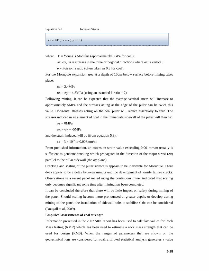
5-38
Equation 5-5 Induced Strain
where E = Young’s Modulus (approximately 3GPa for coal);
σx, σy, σz = stresses in the three orthogonal directions where σz is vertical;
υ = Poisson’s ratio (often taken as 0.3 for coal).
For the Morupule expansion area at a depth of 100m below surface before mining takes
place:
σz = 2.4MPa
σx = σy = 4.8MPa (using an assumed k ratio = 2)
Following mining, it can be expected that the average vertical stress will increase to
approximately 5MPa and the stresses acting at the edge of the pillar can be twice this
value. Horizontal stresses acting on the coal pillar will reduce essentially to zero. The
stresses induced in an element of coal in the immediate sidewall of the pillar will then be:
σz = 8MPa
σx = σy = -5MPa
and the strain induced will be (from equation 5.3):-
εx = 3 x 10⁻³ or 0.003mm/m.
From published information, an extension strain value exceeding 0.001mm/m usually is
sufficient to generate cracking which propagates in the direction of the major stress (σz)
parallel to the pillar sidewall (the σy plane).
Cracking and scaling of the pillar sidewalls appears to be inevitable for Morupule. There
does appear to be a delay between mining and the development of tensile failure cracks.
Observations in a recent panel mined using the continuous miner indicated that scaling
only becomes significant some time after mining has been completed.
It can be concluded therefore that there will be little impact on safety during mining of
the panel. Should scaling become more pronounced at greater depths or develop during
mining of the panel, the installation of sidewall bolts to stabilise slabs can be considered
(Dougall et al, 2009).
Empirical assessments of coal strength
Information presented in the 2007 SRK report has been used to calculate values for Rock
Mass Rating (RMR) which has been used to estimate a rock mass strength that can be
used for design (RMS). When the ranges of parameters that are shown on the
geotechnical logs are considered for coal, a limited statistical analysis generates a value
εx = 1/E (σx – υ (σy + σz)

5-39
for RMR of 56 with a standard deviation of 5.2. This then reduces to a Mining Rock
Mass Rating of 20 with a standard deviation of 2.2 when probable ranges of modifying
factors (weathering, fracture orientation, stress and mining effects) are applied. This value
can be used to calculate RMS (rock mass strength):
Equation 5-6 Rock Mass Strength
RMS = 4.3 +/- 0.5 MPa .
Based on the SRK 2007 report, ATS (Anglo Technical Services) recommend that a Rock
Mass Strength of 7.6MPa is acceptable, similar to the Witbank coalfield No 2 and No 4
seam values, and can be applied to the Morupule seam. That many Morupule pillars have
remained in place for periods exceeding 30 years provides confirmation for ATS that the
design methodology using the Salamon pillar strength has proved acceptable (Dougall et
al, 2009).
Determination of the general system strength for Morupule
The stability of any mining layout depends not only on the strength of individual pillars
but also on the inter-relationship between the panel geometry, barrier pillar resistance and
the nature of the surrounding overburden.
MCL has been granted permission by the Botswana Department of Mines to mine panel 2
South 17 to a design safety factor of 1.6. In SRK’s opinion, this level of monitoring is
insufficient to confirm adoption of a lower safety factor for future mining. It is
recommended that the visual monitoring is supplemented by an instrumentation
programme to gather unambiguous geotechnical data (Dougall et al, 2009).
General conclusions with regard to the coal strength to be used in design: -
1) There is strong evidence to suggest that the strength of the Morupule seam is lower
than that used in the Salamon formula. Ideally, a seam specific strength should be
used.
2) The strength factor for a specific seam should be based on a statistical analysis of
failed and unfailed cases. There are no failed cases at Morupule and therefore this
method cannot be applied.
3) Due to the presence of cleats and rapid changes in microstratigraphy, the laboratory
measured strength of coal is dependent both on the location within the seam from
RMS = UCS – (MRMR – UCS rating)/100

5-40
which the sample is taken and on the sample size. Samples containing exceptionally
weak bands or adversely orientated discontinuities usually either are too difficult to
collect, or are rejected as not being representative. Perversely, these features often
control the behaviour of a pillar. Only once a sample size exceeds about 1.5m does
the size effect reach equilibrium. It is not considered practical to obtain and test large
size samples for this feasibility study.
4) Rock mass classification methods are useful in providing initial estimates of rock
mass strength. A strength value close to 7.2MPa can be obtained when average values
from a limited rock mass parameter information base is applied. When variability
within this information base is considered and cognisance is taken of actual pillar
conditions, a rock mass strength value of 4.3MPa can be obtained. Although this does
reflect a reduction on the Salamon value, there is insufficient confidence in the result
to recommend it for design.
5) Although no failures have been recorded at Morupule since mining commenced, the
amount of scaling recorded suggests that some failures are likely to occur in the
future. Neither the amount of scaling that must take place nor the time required to
develop an unstable geometry have been established. While eventual failures may not
effect underground mining operations, they may cause surface disturbance. If lower
safety factors are to be considered, it is recommended that MCL management give
due consideration to the level of risk that they are willing to accept.
6) SRK understands that trial mining is in progress (2009) to investigate the stability of
a panel that is mined to a safety factor of 1.6. Unfortunately no technical motivation,
assessment criteria, monitoring programme or results have been supplied to SRK for
evaluation. It is recommended that a structured monitoring programme is carried out.
7) For design purposes, SRK recommends that the Salamon formula is retained for this
study and that the uncertainty in its application is accommodated by retaining the
safety factor of 1.8. It is recognised that this may be a sub-economic design but it will
ensure that the risk profile is not significantly higher than has been experienced by
MCL in current workings and will provide a high level of confidence for the
feasibility study (Dougall et al, 2009).

5-41
5.11.4 Pillar loading
The “Tributary Area Theory” of pillar loading assumes that the total overburden load
acting on a pillared area is assumed to be distributed evenly over each pillar.
In reality, the nature of the overburden and the geometric configuration defined by the
depth to span ratio influences the load carried by particular pillars. For a depth to span
ratio greater than 0.5, more of the overburden load is carried by the surrounding barrier
pillars and the tributary area load on panel pillars is reduced. In addition, pillars located
towards the edges of a panel carry less load than those situated closer to the centre. Figure
5.23 (pg. 5-45) illustrates conceptually the change in overburden loading for different
depth to span ratios. Table 5.7 gives depth to span ratios for 7 roadway production panels
that are applicable to Morupule. It can be seen that only in the shallower areas does full
tributary area loading apply. Figure 5.24 illustrates conceptually the variation in loading
on pillars for different panel widths and it can be seen that the pillars adjacent to barriers
carry only about 80% of the load carried by pillars in the centre of the panel. This
variation in loading across the panel assists in explaining different intensities in pillar
scaling that are observed at Morupule. For the purposes of this design, the tributary area
theory is applied.
5.11.5 Mine design
Three main categories of development are identified:
1) Primary Development is the West Main mined in a south westerly direction together
with North Main 4.
2) Secondary Development are the North and South Mains mined from the West Main.
3) Production Sections are developed east and west from secondary development.
4) The values used in the pre-feasibility design for bord widths, mining height, safety
factor are summarised in Table 5.8 (pg. 5-44). Estimates of the probability of failure
for the defined safety factors also are presented (Dougall et al, 2009).

5-42
Table 5-7 Depth to span ratios for 7 roadway production panels
Depth below surface (m)
Pillar width (m) Panel Span
(m)
Depth/Span
50 8.7 102.6 0.49
60 9.9 109.8 0.55
70 11.2 117.6 0.60
80 12.5 125.4 0.64
90 13.9 133.8 0.67
100 15.3 142.2 0.70
110 16.6 150.0 0.73
120 18.0 153.4 0.76
130 19.5 167.4 0.78
140 21.1 177.0 0.79
150 22.6 186.0 0.81
160 24.3 196.2 0.82
170 25.9 205.8 0.83
180 27.5 215.4 0.84
Methodology
In order to determine pillar dimensions and mining efficiencies, the standard Salamon and
Munro approach has been adopted. In this formulation, the following relationships are
defined.
1) Salamon and Munro formulae. The equations used follow:
Equation 5-7 Pillar Strength
where � � pillar width (m) and � � pillar height (m);
Equation 5-8 Squat Pillar Strength
������ �������� ��.� !"
#$.$%%& '(�.) * 181.6. MPa
������ �������� � .��$./%
�$.%% MPa

5-43
where 0 � pillar volume and ( � width to height ratio.
This expression is used for a “squat” pillar when the width to height ratio exceeds 5;
Equation 5-9 Pillar Load
where 1 � depth to seam floor (m) and 2 � bord width (m);
Equation 5-10 Safety Factor
Equation 5-11 Areal Extraction
Equation 5-12 Volumetric Extraction
Where � � economic seam width
Mining parameters for the different development and production phases over the range of
mining depths expected have been calculated and are presented. When the width to
height ratio calculated using the Salamon formula exceeds five, the squat pillar formula
has been used to calculate pillar widths.
Typical failure probabilities associated with specific safety factors that have been
indicated by Salamon are presented in Table 5.8.
With lower safety factors, the risk of failure increases: for example, at a safety factor of
1.6, a value of 1,532 failures in one million can be expected while at a safety factor of
1.4, this rises to 17,000 in one million. The MCL expansion plan indicates that between
03�45����6 78���6��3� �# � �9 �
:
;���� 78���6��3� �9 � 1 <��
�� * 2��
��=��> ?�6�3� �@ABBCD :EDFGHE�
@ABBCD ICJ�
�!!�K./%
LMK�$.%% MPa
������ N3�O � 0.0251��ST�K
�K MPa

5-44
40,000 and 50,000 pillars will be created. At the lower safety factors indicated, Salamon’s
analysis suggests that about 0.2% (70 to 80) of the pillars created could fail when mined
at a safety factor of 1.6. This value rises to 1.7% (up to 350 pillars or approximately one
panel) of the pillars created when the safety factor is reduced to 1.4. In RSA conditions, a
safety factor of 1.6 is used as a design standard while a safety factor of 1.4 is acceptable
for multiple seam operations. If the mining area is subdivided into panels by adequate
barriers and secondary extraction is carried out on retreat, an ultimate safety factor of 1.4
is considered reasonable. Opportunities for improving the overall volumetric extraction
have also been explored. An average economic seam width of 8m has been used.
Variations involving a reduction in safety factor, bottom coaling and roof cutting have
been considered. Mining parameters calculated for improved extraction opportunities are
presented. In shallow areas with less than 40m of cover to the seam floor, particularly
when weathering is prevalent, bord failure rather than pillar collapse becomes the critical
stability factor.
General guidelines for design in shallow conditions are:
1) pillar width should not be less than 5m.
2) width to height ratio should exceed 2.
3) safety factor should be greater than 1.6.
4) areal extraction ratio should not exceed 75%.
For the purposes of the MCL feasibility design, these rules shall be applied at depths of
less than 60m and will affect panels developed on the east side of 2 South Main (Dougall
et al, 2009).
Main development
Primary main development. The objective of design for this main is to create
infrastructure that will remain stable for the life of the mine. A safety factor of two is
considered to be acceptable for critical infrastructure to give a minimal probability of
failure. The mining height is restricted to 4.2m and the bord width to 6.5m.
Recommended mine design parameters for different depths of mining are presented in
Table 5.10 and parameters including an adjustment for squat pillars in Table 5.9.

5-45
Table 5-8 Design parameters used in the pre-feasibility study
Development Bord Width (m) Pillar Height (m)
Safety Factor Probability of Failure
Primary 6.5 4.2 2.0 6 in one million
Secondary 7.0 4.2 2.0 6 in one million
Production 7.2 4.2 1.8 106 in one million
Secondary main development. As with the Primary Main, Secondary Mains may also be
required to remain stable for the life of mining. A safety factor of two is considered to be
acceptable for this critical infrastructure to give a minimal probability of failure. The
mining height is restricted to 4.2m and the bord width to 7.0m (Dougall et al, 2009).
Production panel development
The objective for a production panel is to generate the maximum amount of coal available
at the required production rate.
The panel is required to remain stable for a relatively short working life (between 8 and
12 months); the requirement for ongoing stability depends on factors such as:
1) Any requirement for further extraction.
2) The effect of collapse on adjacent workings (Mains and production panels).
3) The effect of collapse on potentially economic overlying seams.
4) The effect of collapse on surface topography and infrastructure.
MCL and SRK have adopted a minimum risk approach for the purposes of this study and
have retained design parameters that have proved to be effective for mining to date. These
are:
1) Safety factor = 1.8.
2) Bord width = 7.2m.
3) Mining height = 4.2m.
MCL have recognised that these are sub-optimal design parameters and have initiated a
trial panel to investigate the effects of mining at a safety factor of 1.6. To date, the trial
mining panel is not sufficiently far advanced to have generated any meaningful
information to allow a reduced safety factor to be incorporated into the design. Aspects of
trial panel mining and a recommended data collection strategy are discussed in this
report.

5-46
Variation in Pillar Loading Depth to Span Ratios
Figure 5-23
Figure 5-23 Illustration of the variation in pillar loading (Depth to Span Ratios) from
Dougall et al (2009)

5-47
Variation in Pillar Loading Panel Widths Pillars in centre of Panel Higher Stressed
Figure 5-24
Figure 5-24 Illustration of the variation in pillar loading (panel widths) (from Dougall et al
(2009) courtesy SRK Consulting).
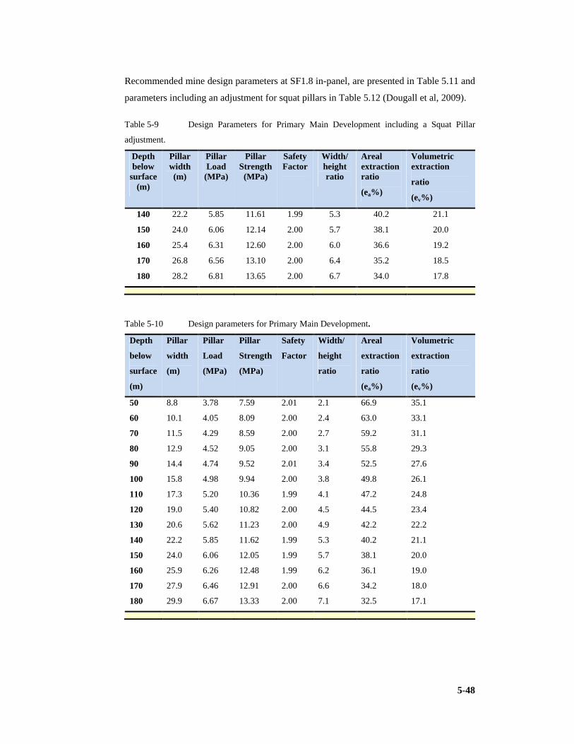
5-48
Recommended mine design parameters at SF1.8 in-panel, are presented in Table 5.11 and
parameters including an adjustment for squat pillars in Table 5.12 (Dougall et al, 2009).
Table 5-9 Design Parameters for Primary Main Development including a Squat Pillar
adjustment.
Depth below
surface (m)
Pillar width (m)
Pillar Load (MPa)
Pillar Strength (MPa)
Safety Factor
Width/ height ratio
Areal extraction ratio
(ea%)
Volumetric extraction
ratio
(ev%)
140 22.2 5.85 11.61 1.99 5.3 40.2 21.1
150 24.0 6.06 12.14 2.00 5.7 38.1 20.0
160 25.4 6.31 12.60 2.00 6.0 36.6 19.2
170 26.8 6.56 13.10 2.00 6.4 35.2 18.5
180 28.2 6.81 13.65 2.00 6.7 34.0 17.8
Table 5-10 Design parameters for Primary Main Development.
Depth
below
surface
(m)
Pillar
width
(m)
Pillar
Load
(MPa)
Pillar
Strength
(MPa)
Safety
Factor
Width/
height
ratio
Areal
extraction
ratio
(ea%)
Volumetric
extraction
ratio
(ev%)
50 8.8 3.78 7.59 2.01 2.1 66.9 35.1
60 10.1 4.05 8.09 2.00 2.4 63.0 33.1
70 11.5 4.29 8.59 2.00 2.7 59.2 31.1
80 12.9 4.52 9.05 2.00 3.1 55.8 29.3
90 14.4 4.74 9.52 2.01 3.4 52.5 27.6
100 15.8 4.98 9.94 2.00 3.8 49.8 26.1
110 17.3 5.20 10.36 1.99 4.1 47.2 24.8
120 19.0 5.40 10.82 2.00 4.5 44.5 23.4
130 20.6 5.62 11.23 2.00 4.9 42.2 22.2
140 22.2 5.85 11.62 1.99 5.3 40.2 21.1
150 24.0 6.06 12.05 1.99 5.7 38.1 20.0
160 25.9 6.26 12.48 1.99 6.2 36.1 19.0
170 27.9 6.46 12.91 2.00 6.6 34.2 18.0
180 29.9 6.67 13.33 2.00 7.1 32.5 17.1
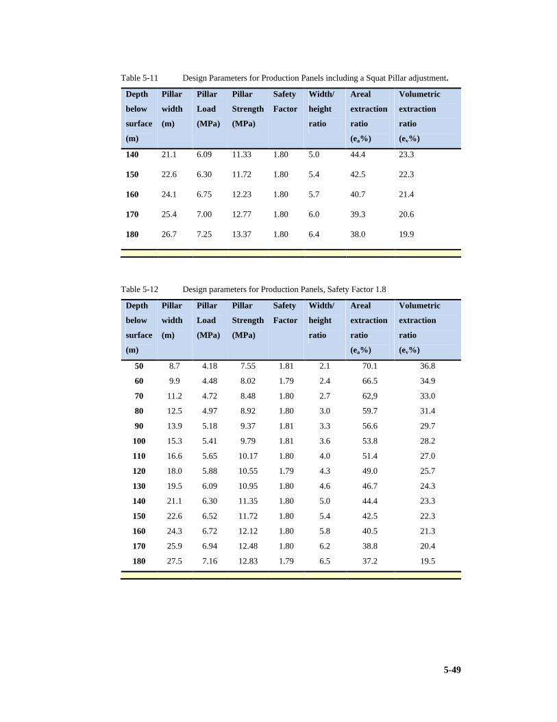
5-49
Table 5-11 Design Parameters for Production Panels including a Squat Pillar adjustment.
Depth
below
surface
(m)
Pillar
width
(m)
Pillar
Load
(MPa)
Pillar
Strength
(MPa)
Safety
Factor
Width/
height
ratio
Areal
extraction
ratio
(ea%)
Volumetric
extraction
ratio
(ev%)
140 21.1 6.09 11.33 1.80 5.0 44.4 23.3
150 22.6 6.30 11.72 1.80 5.4 42.5 22.3
160 24.1 6.75 12.23 1.80 5.7 40.7 21.4
170 25.4 7.00 12.77 1.80 6.0 39.3 20.6
180 26.7 7.25 13.37 1.80 6.4 38.0 19.9
Table 5-12 Design parameters for Production Panels, Safety Factor 1.8
Depth
below
surface
(m)
Pillar
width
(m)
Pillar
Load
(MPa)
Pillar
Strength
(MPa)
Safety
Factor
Width/
height
ratio
Areal
extraction
ratio
(ea%)
Volumetric
extraction
ratio
(ev%)
50 8.7 4.18 7.55 1.81 2.1 70.1 36.8
60 9.9 4.48 8.02 1.79 2.4 66.5 34.9
70 11.2 4.72 8.48 1.80 2.7 62,9 33.0
80 12.5 4.97 8.92 1.80 3.0 59.7 31.4
90 13.9 5.18 9.37 1.81 3.3 56.6 29.7
100 15.3 5.41 9.79 1.81 3.6 53.8 28.2
110 16.6 5.65 10.17 1.80 4.0 51.4 27.0
120 18.0 5.88 10.55 1.79 4.3 49.0 25.7
130 19.5 6.09 10.95 1.80 4.6 46.7 24.3
140 21.1 6.30 11.35 1.80 5.0 44.4 23.3
150 22.6 6.52 11.72 1.80 5.4 42.5 22.3
160 24.3 6.72 12.12 1.80 5.8 40.5 21.3
170 25.9 6.94 12.48 1.80 6.2 38.8 20.4
180 27.5 7.16 12.83 1.79 6.5 37.2 19.5

5-50
5.11.6 Roof support and its optimisation
The horizon control strategy employed at MCL aims at maintaining 1.5m of coal in the
floor. For an average seam thickness of 8m and a normal mining height of 4.2m, an
average thickness of 2.3m of coal can be expected to remain in the roof. This coal roof is
overlain by carbonaceous mudstone. Roof support at MCL therefore currently is required
to maintain a stable roof beam in coal. Should bottom coaling be practiced, it is likely that
the initial cut will be taken at a higher level in the seam to maximise bottom coaling
efficiency. The coal roof thickness will decrease and consideration will have to be given
to anchoring roofbolts in carbonaceous mudstones.
The support layout currently employed is four 1.2m long full column resin grouted bolts
are installed 1.4m apart in each row. Rows are located 1.5m apart. This provides for an
average bolt density of 1bolt per 2.1m2. The roofbolt density applied at MCL is higher
than would normally be required for a coal roof. It is recommended that a study is
initiated to fully quantify support effectiveness and to identify opportunities for
improving support efficiency.
Assuming that a beam 1m thick is to be supported by suspension from a roof bolt 1.2m in
length, the average load imposed on each bolt is 44.5kN (assuming a coal density of
1,650kg/m³; i.e. mean plus one standard deviation). Typically an 18mm roofbolt will have
an ultimate strength of approximately 170kN. The safety factor for suspension therefore
is 3.8. This is not to be confused with the pillar safety factor but the ratio of bolt strength
to bolt load.
This estimate presumes that the shear forces generated in the remaining 200mm bonded
portion of the roofbolt do not exceed the shear strength of the bolt/resin interface, the
resin or the resin/rock interface. The shear force generated at the bolt/resin interface is
approximately 3.9MPa and 3.2MPa at the resin/coal interface. These values are close to
the maximum values experienced in RSA collieries. It is recommended that short
encapsulation pull tests are carried out to quantify shear strength values that are
applicable to MCL. Short encapsulation pull tests should also be carried out in the
overlying carbonaceous mudstones to provide design information for support design for
possible future bottom coaling operations. Pull tests have been carried out in the past and
SRK found these results to be consistent and did not present cause for concern.
The mine operations generally use only 1.2m bolts in normal risk ground and 1.8m bolts
in disturbed ground.

5-51
For an average monthly consumption of 6,300 bolts, the unit bolting cost amounts to
BWP54.30/bolt. At an average monthly production of 85,000t, the bolting cost amounts
to BWP4.02/t.
Three sonic probe extensometers were installed in the West Main to heights between 7m
and 8m above the coal roof. Measurements were made over a period of approximately
seven months and plotted as time displacement graphs. ATS have interpreted the results
as indicating roof softening only over the initial 200mm of roof related to weak partings
within the coal and have proposed the current design accordingly. In SRK’s opinion, the
measurements are ambiguous and indicate unexplained displacements much higher into
the roof. These may be a function of the errors in the measurement system or may be due
to natural displacements. Borescope examinations and logging of core from the roof
section measured are necessary to assist in identifying reasons for the general softening
and the occurrence of the displacement “spikes” observed.
It is recommended that an investigation is carried out to fully characterise roofbolt
performance and to gather information for the design of support systems at greater depths
of mining. The programme should use strain gauged roofbolts, roofbolt load cells,
extensometers and borescope observations to quantify the response of the roof strata to
different support systems. For example, it may be found that a system using 1.2m long
bolts may prove capable of supporting the immediate roof but may prove incapable of
creating a beam that is sufficiently stiff to prevent bed separation in overlying strata with
consequent roof loading and possible collapse, as mining depth increases in coming years
(Dougall et al, 2009).
5.11.7 Inter-panel / barrier pillars
Currently there is no formalised barrier pillar design approach in use on the Southern
African collieries. ATS has recommended that the barrier pillar width should be twice the
panel pillar width. This would ensure that a minimum width to height ratio of 4:1 is
achieved at shallower depths rising to 10:1 or more at greater depths.
Computer modelling using MAP3D (a fully integrated three dimensional layout (CAD),
visualisation (GIS) and stability analysis (BEM numerical modelling stress analysis)
package) has been used to estimate stress acting in a barrier pillar at 100m depth for a
range of mining heights from 4.5m to 6.5m. The computed average pillar stress ranges
from 3.46MPa to 3.52MPa over these heights. Safety factors fall from 3.2 to 2.4.

5-52
The purpose of a barrier pillar in a shallow mining layout generally is not considered to
be that of a load carrying structure but rather a means of separating and isolating adjacent
panels for the purposes of ventilation, gas, water and fire control. Barrier pillars also are
expected to constrain any pillar failure that may occur. At the envisaged mining depths at
MCL, the width of a seven road panel invariably will be greater than the depth to the
seam and the tributary area theory, in which the overburden load is capable of being
carried by the panel pillars, is applied. It is recommended therefore that the barrier pillar
width applied to the feasibility design should be taken as equal to the panel pillar width at
the comparable depth. It is further recommended that additional modelling of the range of
barrier pillar widths likely to be encountered is undertaken and that an instrumentation
programme is initiated to provide calibration for numerical models (Dougall et al, 2009).
5.11.8 Underground dams
A series of design charts for the design of barrier pillars to provide hydraulic stability in
coal mines has been prepared as part of SIMRAC project COL702.
Hydraulic Design Chart for a Coal
Bounded Barrier Pillar Figure 5-25
Figure 5-25 Hydraulic design chart for a coal bounded barrier pillar (from Dougall et al,
2009)

5-53
Use of the charts allows determination of the minimum barrier pillar width to restrict
leakage to predetermined values for a given head of water.
Figure 5.25 illustrates a design chart applicable to workings in which both roof and floor
consist of coal.An illustrative example indicates that a flow of approximately 25Ml per
month per km of pillar length can be expected for a pillar 25m wide at a depth of 120m
below surface and subjected to an average hydraulic head of 25m (Dougall et al, 2009).
5.11.9 Risk assessment of the design
General hazard overview
Hazards that are likely to be encountered in coal mines are summarised in Table 5.14. A
typical likelihood matrix is presented in Table 5.13. The hazards have been assessed
qualitatively for the MCL environment taking cognisance of the controls that are in place
to provide an indication of the baseline geotechnical risk profile of the mine. It is
concluded that the current risk profile is low. It is recommended that a full baseline risk
assessment is conducted in conjunction with mine staff (Dougall et al, 2009).
Table 5-13 Likelihood descriptions
Likelihood descriptor Frequency Extremely low Unlikely to occur within the life of the mine Very low May occur at 1 to 5 year intervals Low May occur annually Moderate May occur monthly High May occur weekly Very high Likely to occur each shift
Quantitative risk assessment
Typical failure probabilities in terms of the number of likely pillar failures that have been
estimated for specific safety factors by Salamon are presented in Table 5.15 (pg. 5-57). At
a design safety factor of 1.8, 106 failures could be expected in one million pillars. That
translates to potentially five pillar failures over the expected life of the expansion project.
With lower safety factors, the risk of failure increases. At a safety factor of 1.6, 1,532
failures in one million can be expected while at a safety factor of 1.4, this number rises to
17,000 in one million. The MCL expansion plan indicates that between 40,000 and
50,000 pillars will be created. At the lower safety factors indicated, Salamon’s analysis
suggests that about 0.2% (70 to 80) of the pillars created could fail when mined at a
safety factor of 1.6. This value rises to 1.7% (up to 350 pillars or approximately one
panel) of the pillars created when the safety factor is reduced to 1.4.

5-54
In RSA conditions, a safety factor of 1.6 generally is used as a design standard while a
safety factor of 1.4 is acceptable for multiple seam operations. If the mining area is
subdivided into panels by adequate barriers and secondary extraction is carried out on
retreat, an ultimate safety factor of 1.4 is considered reasonable.
SRK has developed a fault event tree approach to be able to assess the level of risk
associated with any design. This method has been applied widely to the design of large
slopes (slope stability engineering) in hard rock. Starting with the probability of a fault
event, in this case a pillar failure, the tree follows a series of routes through tests and
control systems to which probabilities of effectiveness are applied and the overall
probabilities of specific outcomes are assessed. For this design the tests and controls
considered are:
1) Given that a pillar system fails, the failure takes place within the operating life of the
panel. The probability of this happening is taken as 0.25 based on time to failure
information presented in the ATS report. In SRK’s opinion, this is severe as reference
to original work by Salamon, Ozbay and Madden (1998) indicates that less than 10%
of pillars with a design safety factor of 1.4 or greater failed within the first year. The
value is retained however to provide additional conservatism to the methodology;
2) Given that monitoring systems are installed, the probability of a monitoring system
detecting the onset of failure is assumed to be 90% (0.9). This is a conservative value
as any pillar failure would provide indications of distress in such as rapid scaling and
bumping which would be detectable visually and audibly for some considerable time
before collapse occurred;
3) Given that evacuation systems are in place, the probability of the system leaving
personnel exposed to the failure is assumed to be 10% (0.1). This is a conservative
value as the symptoms of the onset of failure would lead to precautions being taken
such as the barricading off of specific areas and restriction of access to all but
essential personnel.
Illustrative fault event trees for design cases at a safety factor of 1.8 and 1.4 are shown in
Figures 5.26 and 5.27 respectively with calculated probabilities based on the assumed
probabilities listed above. It is emphasised that these values are based on assumptions of
effectiveness that could be experienced by MCL. A more detailed analysis is required to
improve confidence in the result. In SRK’s opinion, the values chosen are sufficiently
realistic to provide an indication of the inherent risk for feasibility level purposes.
Guidelines on risk acceptance prepared by the United Kingdom Health and Safety
Executive are presented in Figure 5.28. Table 5.15 summarises the outcomes of the fault

5-55
Table 5-14 Generalised baseline geotechnical risk assessment
Hazard/risk Existing controls
Likelihood with
existing controls
Comments
Falls of scaled materials from pillar sidewalls
Inspection. Spot bolting. Barring practice
Moderate to low
A time related response, not likely to occur in mining sections. A significant hazard where rehabilitation is taking place
Falls of wedge shaped blocks defined by slips
Inspection. Spot bolting. Barring practice
Moderate to low
Observed in panel 2 South 17. Well supported
Widespread pillar collapse
Conservative pillar design
Extremely low
A probabilistic assessment of this scenario is developed in section 5.7.2 of the Geotechnical Report
Falls from the carbonaceous shale roof
Horizon control to create a thick coal roof
Low May occur if horizon control is not maintained. Possible in areas showing deterioration in the West Main and RAW,s
Falls of coal roof Systematic support pattern
Low The dense support pattern provides suspension and beam building functions (section 5.4of the geotechnical report)
Falls of roof due to slips
Inspection. Systematic and special support rules
Low A special support rule requires that slips are supported within 0.5m on either side with bolts 1.0m apart (MCL 124)
Falls of brows Inspection. Systematic support
Moderate As far as SRK is aware, no special support rule has been generated.
Collapse of weathered roof strata
Special support installation.
Moderate to low
Limited to shallow areas and parts of the West Main and RAW’s. Examination indicated that support systems installed were effective.
Support incorrectly installed
Standard procedures
Moderate to low
SRK did not review the standard operating procedure. Resin management appeared to be effective.
Off-line mining creates wide bords and intersections. Increased risk of falls of roof
Standard operating procedure for maintaining line and grade. Operator training
Moderate to low
Observed in the West Main where rehabilitation and removal of scaled material has changed initial geometries. Additional support may be necessary
Personnel do not recognise adverse conditions and fall of ground precursors
Training. Supervision. Coaching.
Moderate to low
Critically dependent on successful implementation of the controls
Uncontrolled surface subsidence
Effective design and support
Low to very low
An incident has been reported in the shallower portion of the mine. Not possible to inspect sealed off sections so other cases could occur. Periodic surface inspection is required.

5-56
event process. The probability of incurring an injury due to pillar failure for a design
safety factor of 1.8 is estimated to be 2.65 x 10⁻⁷ which can be considered to be of no
concern. At a design safety factor of 1.4, the probability of incurring an injury due to
pillar failure increases to 4.25 x 10⁻⁴. According to Figure 5.26, this level of risk may be
considered as justifiable for a situation in which 10 to 20 people are exposed (Dougall et
al, 2009).
Table 5-15 Summary of probabilities for different monitoring and evacuation system
effectiveness.
Scenario Safety Factor = 1.8
Safety Factor = 1.4
No pillar failure. No injury 7.95 x 10⁻⁶ 1.28 x 10⁻²
Pillar failure occurs. Monitoring and evacuation systems are effective. No injury.
2.1 x 10⁻⁶ 3.44 x 10⁻³
Pillar failure occurs. Monitoring is effective but the evacuation system fails and people are exposed. Possible injury to personnel.
2.39 x 10⁻⁷ 3.83 x 10⁻⁴
Pillar failure occurs. The monitoring system fails but evacuation is effective. No injury.
2.39 x 10⁻⁷ 3.83 x 10⁻⁴
Pillar failure occurs. Both monitoring and evacuation systems fail. Possible injury to personnel
2.65 x 10⁻⁸ 4.25 x 10⁻⁵
Event Consequence Tree Pillar System Safety Factor 1.8
Figure 5-26
Figure 5-26 Event-consequence tree for a pillar system designed at safety factor 1.8 (from
Dougall et al, 2009)

Figure
safety factor 1.4
Figure
(based on Salamon and Hartford, 1995)
Figure 5-27
safety factor 1.4
Figure 5-28
(based on Salamon and Hartford, 1995)
Event-consequence tree for a pillar system designed with bottom coaling at
safety factor 1.4 (from Dougall et al, 2009).
United Kingdom Health and Safety Executive Guidelines on Risk Acceptance
(based on Salamon and Hartford, 1995)
Event Consequence Tree Pillarwith Bottom Coaling at SF=1.4
consequence tree for a pillar system designed with bottom coaling at
(from Dougall et al, 2009).
UK Health & Safetyon Risk Acceptance
United Kingdom Health and Safety Executive Guidelines on Risk Acceptance
(based on Salamon and Hartford, 1995)
Event Consequence Tree Pillarwith Bottom Coaling at SF=1.4
consequence tree for a pillar system designed with bottom coaling at
(from Dougall et al, 2009).
UK Health & Safety Executive Guidelines on Risk Acceptance
United Kingdom Health and Safety Executive Guidelines on Risk Acceptance
Event Consequence Tree Pillar System with Bottom Coaling at SF=1.4
consequence tree for a pillar system designed with bottom coaling at
Executive Guidelines on Risk Acceptance
United Kingdom Health and Safety Executive Guidelines on Risk Acceptance
System Figure 5
consequence tree for a pillar system designed with bottom coaling at
Executive Guidelines Figure 5
United Kingdom Health and Safety Executive Guidelines on Risk Acceptance
5-57
Figure 5-27
consequence tree for a pillar system designed with bottom coaling at
Figure 5-28
United Kingdom Health and Safety Executive Guidelines on Risk Acceptance

5-58
5.11.1 Opportunities for improved extraction
This may be achieved through reduction of safety factor in panel to 1.4 or through
secondary mining through bottom coaling and eventually pillar extraction once resistance
by the Mines Department is overcome.
Mining height
Top coaling and maximisation of cutting height. MCL have made a decision to leave at
least 1m of coal in the roof of the bords to minimise the risk of cutting into the overlying
carbonaceous mudstones and creating poor roof conditions. This is a widely accepted
practice in RSA coal mines, particularly in the No 2 seam. In many instances, the beam of
coal is sufficiently competent to span a roadway 6.5 to 7.5m in width. Installation of a
support system such as that described, enhances roof stability.
Unfortunately, if a steel tendon based roof support system has been installed, further
cutting of the roof in a top-coaling operation becomes difficult and the risk of cutter head
damage or belt tears caused by sharp steel fragments is increased. MCL therefore have
made the decision not to pursue a conventional, second pass, top-coaling option.
Currently, the mining height developed using the Joy 12HM31 continuous miner is
restricted to 4.2m. This machine has the potential to cut to 4.5m. Table 5.16 indicates the
potential increase in volumetric extraction that can be achieved by increasing the cut
height while maintaining a safety factor of 1.8. The bord width is maintained at 7.2m.
Bottom coaling. Bottom coaling has been practiced in several sections at Morupule and
the mine has gained experience and confidence with the method. Mining heights of 6m
have been achieved. ATS recommend a maximum height of 5.85m for bottom coaling.
This restriction has been based on an analysis at a single depth, 100m, and using the
criteria that the safety factor must not fall below 1.3 and the width to height ratio should
not be less than 2 after a predetermined amount of pillar scaling have occurred.
Design parameters for a standard bottom coaling panel mined with a bord width of 7.2m
to a final height of 6m to give a safety factor of 1.8 are shown in Table 5.17.
For this case, only mining at depths less than 60m, is scaling likely to reduce the width to
height ratio to less than 2.
This could influence some production panels to the east of South Main 2. Should
significant sidewall scaling be found to occur in practice, sidewall bolting can be
employed to effect short term safety and improve longer term stability.

5-59
Safety factor reduction
Currently, South 2 panel 17 has been designated as a trial panel to assess conditions
arising when mining takes place with a safety factor of 1.6 (Dougall et al, 2009).
Maximisation of extraction
Areal and volumetric extraction ratios have been calculated for each of the production
mining scenarios considered and presented. The variation in volumetric extraction ratio
with depth for each of the production mining scenarios is shown in Table 5.16 and Table
5.17 to illustrate the effectiveness of different approaches with respect to the base case.
Table 5-16 Design parameters for maximisation of the cut height.
Depth
below
surface
(m)
Pillar
width
(m)
Pillar
Load
(MPa)
Pillar
Strength
(MPa)
Safety
Factor
Width/
height
ratio
Areal
extraction
ratio
(ea%)
Volumetric
extraction
ratio
(ev%)
50 9.0 4.05 7.33 1.81 2.0 69.1 38.9
60 10.3 4.33 7.80 1.80 2.3 65.4 36.8
70 11.6 4.60 8.24 1.79 2.6 61.9 34.8
80 13.0 4.83 8.68 1.80 2.9 58.6 33.0
90 14.4 5.06 9.10 1.80 3.2 55.6 31.3
100 15.8 5.30 9.50 1.79 3.5 52.8 29.7
110 17.3 5.52 9.90 1.80 3.8 50.1 28.2
120 18.9 5.72 10.31 1.80 4.2 47.6 26.8
130 20.5 5.93 10.71 1.80 4.6 45.2 25.4
140 22.1 6.15 11.08 1.80 4.9 43.1 24.2
150 23.7 6.37 11.44 1.80 5.3 41.2 23.2
160 25.5 6.58 11.84 1.80 5.7 39.2 22.0
170 27.3 6.79 12.21 1.80 6.1 37.4 21.0
180 29.2 6.99 12.60 1.80 6.5 35.6 20.1
It is evident that bottom coaling must be practiced if any significant increase in
volumetric extraction is to be achieved. MCL must target achieving a 6m high cut to
create pillars with a final safety factor after mining of 1.4. It should be noted that a
bottom coaling cut between 1.5m and 1.8m high has been assumed in this analysis to
restrict a final pillar height to 6m. This would allow for an average of 1m of coal to be
left to protect each of the roof and floor. A greater width of bottom coaling cut could be
taken if this proves to be feasible from practical mining and sidewall stability aspects.

5-60
It is noted that the width of a pillar that is created by cutting with a continuous miner can
be reduced compared with that created by drilling and blasting for a given set of mining
conditions. This “continuous miner adjustment” has not been applied in this analysis as
SRK considers that the additional refinement is not warranted given the level of
uncertainty in design parameters (Dougall et al, 2009).
Table 5-17 Design parameters for standard bottom coaling, safety factor 1.8
Depth
below
surface
(m)
Pillar
width
(m)
Pillar
Load
(MPa)
Pillar
Strength
(MPa)
Safety
Factor
Width/
height
ratio
Areal
extraction
ratio
(ea%)
Volumetric
extraction
ratio
(ev%)
50 10.3 3.61 6.45 1.79 1.7 65.4 49.0
60 12.0 3.84 6.92 1.80 2.0 60.9 45.7
70 13.6 4.09 7.33 1.79 2.3 57.2 42.9
80 15.3 4.33 7.74 1.79 2.6 53.8 40.3
90 17.1 4.54 8.15 1.79 2.9 50.5 37.9
100 19.0 4.75 8.55 1.80 3.2 47.4 35.6
110 20.9 4.97 8.93 1.80 3.5 44.7 33.5
120 23.0 5.17 9.34 1.80 3.8 42.0 31.5
130 25.0 5.39 9.70 1.80 4.2 39.7 29.8
140 27.0 5.62 10.05 1.79 4.5 37.7 28.3
150 29.3 5.82 10.44 1.79 4.9 35.6 26.7
160 31.7 6.02 10.82 1.80 5.3 33.6 25.2
170 33.9 6.25 11.16 1.79 5.7 32.0 24.0
180 36.5 6.45 11.85 1.79 6.1 30.2 22.7
5.12 Conclusions
1) The mining engineer will normally utilise the specialised skills of a rock
engineering team on the design team.
2) To enable increased extraction knowledge of rock properties is required.
3) The rock engineer makes a strong contribution to mining method and orientation.
4) Secondary mining requires strategies to enhance percentage extraction and the
initial design must accommodate the final action with consideration of safety
factors.

5-61
5) Salamon formulae are very effective although certain rock engineering
practitioners are advocating the use of numerical modelling techniques for pillar
design.
6) Panels and developments need to be designed in specific detail.
7) Hydrological barriers or pillars left to ensure confinement will require special
consideration.
8) Bord widths and pillar sizes and mining height remain critical to stability.
9) Roof falls are more prevalent in intersections.
10) Surface protection and avoidance of subsidence could inflict serious constraint on
the mining operation.
11) The attitudes of governmental agencies also influence the effectiveness of the
design as to the allowance of secondary methods and the dictation of safety
factors.
12) The mining engineer that has a strong appreciation of rock engineering is better
suited to perform the design.

6-1
6 CHOICE CONSIDERATIONS
6.1 Introduction
The purpose of this section is to establish a conceptual framework within which the
various options, open to the mining engineer faced with a choice of methods for a given
deposit, may be discussed. It will outline the factors that influence the choice the mining
engineer may have in finally selecting a mining system and method of winning the coal
for the given ore deposit.
There are numerous factors that may be grouped into three broad parameters,
technological, economic and geological (Buchan et al, 1981).
It is of the utmost importance that a conscious and systematic analysis of each of these
factors be made before finally selecting a mining system and/or a coal winning method,
as ad hoc decisions in this regard could affect detrimentally the final percentage
extraction achieved, thus detracting from the optimal utilisation of available reserves.
Making the correct choice leads to best practice systems.
6.2 Opencast versus Underground Mining.
Before one can consider the increased extraction of coal by underground mining methods,
some reference should be made to the cut-off parameters between underground and
opencast mining.
The first large opencast coal mining operation in the Republic was commenced in 1971
(Optimum colliery). Until that time coal reserves with an overburden of less than 25m
were not always mineable. When opencast operations were started in the country, a depth
of overburden of some 30 to 35m was considered as being the cut-off point for opencast
mining operations. Coal seams at depths of up to 90m are being mined currently by
opencast methods, and large walking draglines have become an integral part of the scene
in the coalfields. A stripping ratio of 6:1 is generally considered feasible. Stripping ratio
is defined as the ratio of bench cubic metres to tonnage of coal in situ hence is six BCM
(bench or insitu m3) overburden to one tonne coal in situ. The above forms leave units
and therefore are not true ratios. Phillips argues for units to cancel in the dimensional
analysis “stripping ratio must be in linear equivalent units i.e. metres overburden to
6-2
metres coal (linear thicknesses) or volumes to volumes” (Phillips, Personal
communication, 2010).
It is also important to understand the impact of moisture content in the coal and the
difference between air-dried uncontaminated and as received. The difference lies in the
moisture concentration in the coal.
This researcher is of the opinion that collieries that should have originally been developed
using surface mining techniques were instead developed using conventional bord and
pillar equipment as this was readily available at the time of establishment. A typical
example is Morupule Colliery Limited. This mine will be used as a case study in many of
the subsequent chapters.
6.3 Geological Parameters
Coal reserves in South Africa are found in sediments of Permian age which overlie a
large area of the country. They generally occur as fairly thick, flat, shallow-lying coal
seams (Fauconier & Kersten, 1982), affirmed by Falcon (1986) and Anderson, J. &
Anderson, H. (1985).
Of the geological parameters, the composition and thickness of strata overlying the coal
seams, the parting between seams and the thickness of coal seam, are considered to be the
most important factors.
The composition and thickness of the strata overlying the coal seams is the single most
important parameter affecting the choice of mining system. In the case of open-cast
mining methods, it determines the overburden-to-coal ratio, (stripping ratio) which, in
turn, is of paramount importance as far as the economics of opencast mining are
concerned (Fauconier & Kersten, 1982).
Fauconier states, “The strata composition and in particular, the strength properties of the
different layers have a significant effect on the cost of the overburden removal as the
drilling of the blast holes, the burden between successive blast holes and the specific
explosive consumption are affected by these properties” (Fauconier & Kersten, 1982).
Coal hardness and abrasiveness or the presence of abrasive bands is significant when
cutting systems are employed. These (hardness and abrasiveness) impacts on pick
consumption, one of the factors that influences shearer and continuous miner
performance significantly (Dougall et al, 2009). It will also impact the specific energy
needed to cut the coal as it is directly proportional to coal hardness.

6-3
All geological factors have a significant potential of influencing mining conditions.
Dolerite or other igneous intrusions and the presence of isolated blocks create problems
with continuity and will influence the equipment chosen as well as the methodology
applied. Regular blocks of undisturbed coal is easily exploited using wall methods or
pillar extraction processes but this is also related to the caving characteristics or
propensity to cave of the strata. Competent beams of thick Sandstone and Igneous rocks
may impede caving and hence force reconsideration.
6.4 Technological Parameters
Fauconier (1982) commented on technology as a factor. “Mining technology on its own
places the least constraint on the choice of a mining system. In the case of open-cast coal
mining the technology is available to extract coal seams under most conditions of
overburden to depths well in excess of 50m. When examining the technology, due
consideration should be given to the tonnage of coal to be produced and the ability to
remove overburden at a rate comparable to the required tonnage, in other words, the
dragline must be able to uncover sufficient coal to meet the production demand. . Success
could well ride on, the correct choice, having been made” (Fauconier & Kersten, 1982).
In the opinion of this researcher the case of underground mining technology in certain
capital intensive systems, such as Wall Mining and in systems using Continuous Haulage,
technology becomes more critical.
The choice currently resides in the differences of application of Wall systems relative to
Bord and Pillar systems and the application of batch haulage systems against continuous
haulage systems.
6.5 Economic Parameters
This researcher knows that in the case of Morupule colliery the cost of capital becomes a
major factor in the decision and where capital intensive processes would have been
preferred the challenge of raising the necessary funding for the capital is not always
possible. Wall systems are far more capital demanding or expensive than batch systems
when acquisition takes place but often provide reduced operating costs due to economies
of scale and in being less labour intensive. A similar trade off study is required when
draglines are considered in Surface mining. Often these are to capital intensive for the
current financial gearing structure of the company and often a suitable truck and shovel

6-4
operation is implemented to move the overburden as opposed to the casting device or
bucket wheel excavating system.
Fauconier and Kersten identified that “Economic considerations ultimately are the most
important factors affecting the choice of mining methods. In the case of open-cast mining,
the coal-to-waste ratio is generally seen as the most important parameter. These ratios, in
turn, will depend on factors such as the quality of coal, the price of coal, the availability
of capital, etc. Taking the coal-to-waste ratio as a critical parameter for the application of
opencast methods, it follows that this method of mining is confined to comparatively
thick seams at relatively shallow depths” (Fauconier & Kersten, 1982).
This research will be confined to underground mining methods and, as a general rule, will
be confined to the mining of reserves where the overburden thickness is in excess of 25 to
30m (a dimension needed to ensure roof integrity). A wide variety of methods exist from
which a choice must be made when contemplating the mining of coal reserves by
underground methods. With all these possible methods available, there are many factors
that will have an influence on the method or combination of methods that may be chosen
(Buchan et al, 1981).
Many factors have been identified on authority of Buchan et al (1981), Jeffery (2002) and
others were identified as important by an experienced team of consultants, Prinsloo et al
(2008) during an actual pre-feasibility conducted.
6.6 Geometrical Factors
Buchan et al (1981) identified that, “Geometrical factors basically deal with
measurements or 'shape' factors that influence the choice of mining methods” (Buchan et
al, 1981). Geometrical factors are discussed in sections 6.6.1 to 6.6.3:
6.6.1 Thickness of overburden
“The thickness (and composition) of the super-incumbent strata can have an overriding
influence on mine design for all mining methods. In particular, it can influence the panel
width, size of inter-panel pillars and roadway support, amongst others. In the case of
conventional bord and pillar mining the thickness of the rock strata above the coal seam
determines the weight of strata that has to be supported by pillars and therefore is a major
determinant in design calculations. The composition of the immediate roof strata will
influence the choice of bord width and local roof support.

6-5
Buchan et al stated, “The thickness and composition of the upper roof strata determines
the manner in which mining-induced stresses are redistributed. For example, in the case
of caving methods, the factor of prime importance is the thickness of dolerite that
sometimes forms massive sills above the coal seam. This dolerite usually has a great
bearing on the caving characteristics of the overburden and, thus, on the magnitude and
distribution of abutment stresses” (Buchan et al, 1981).
6.6.2 Multiple seams
Fauconier (1982) reproduced Buchan’s comments in his editorial and argues with respect
to multiple seams, “In most coal mining areas of this country the coal resources are
contained in more than one mineable seam. Therefore, to improve the extraction of
available reserves it is imperative that consideration be given to the mining of multiple
seams. The composition and thickness of partings between seams is a critical geological
as well as geometrical parameter affecting the design and layout of underground
workings. The presence of more than one coal seam often imposes severe constraints on
the choice of underground mining methods, mine layout, and mining sequence. In the
case of bord and pillar mining, the interaction between pillars in different seams has to be
taken into account when designing pillars and mine layouts” (Buchan et al 1981). Four
basic situations have been distinguished, namely:
1) “The seams are of the order of two to three pillar centre distances apart and so do
not interact at all.
2) The seams are of the order of one to two pillar centre distances apart and, as a
result, some interaction between pillars may occur. In this case barrier pillars in
different seams may need to be superimposed.
3) The thickness of parting between seams is of the order of the pillar centre
distance. In this case both panel and barrier pillars should be superimposed and
the safety factor of the pillars in each seam should be at least 1.7.
4) The parting between seams is less than 1.5 times the bord width. In this instance,
failure of the parting between seams cannot be excluded. Therefore, a safety factor
of at least 1.4, based on a combined working height of the two seams must be
observed. In addition, the safety factor of the individual seam workings should
exceed 1.8” (Fauconier & Kersten, 1982).
The sequence of mining is non-critical except in areas where the parting is very thin. In
these cases it is usual to extract the top seam first. Where this possibly is not adequate, or
is not possible, support should be installed in the lower seam to ensure that the parting

6-6
between the two seams, which is the working floor for the upper seam, remains intact. To
quote Buchan et al (1981), “In the case of panel mining (pillar extraction, longwall, etc)
the uppermost seam, as a general rule, should be extracted first. It should be noted that
this general rule does not necessarily apply in the case of very steep dipping coal seams
or when stowing is incorporated into the mining method. Inter-panel pillars should be
superimposed and the development in the lower seam should be located beneath already
mined-out areas, wherever this is practical. As a consequence of this rule, the width of
pillars between total extraction panels tends to increase in the second or third seam”
(Buchan et al, 1981).
On existing collieries, situations arise where one or several seams have been extracted
using conventional bord and pillar methods and panel mining is contemplated in one of
the yet unmined seams. Careful consideration has to be given in these hybrid mining
situations to the effect of abutment stresses (which develop at the edges of the total
extraction panel) on the stability of bord and pillar working in the neighbouring seams.
Abutment stresses in excess of 1.5 times the primitive stresses frequently occur in the
vicinity of total extraction panels, these stresses are sufficient to induce pillar failures in
neighbouring seams, particularly if the design safety factor of these workings is low.
Apart from the potential dangers associated with uncontrolled pillar collapses, the effects
of these failures on the total extraction panel need to be considered as well. In the case of
undermining a bord and pillar area, these effects probably are small. In the case of over
mining a bord and pillar panel with a longwall face, a collapse of pillars in the lower
seam could have serious effects on the extraction panel and the access roads to these
panels. Note the conclusion by Van der Merwe & Madden (2002), “As a general rule,
over mining bord and pillar workings with a longwall should be avoided except possibly
in cases where the pillars were designed to a very high safety factor and the parting
between the two seams is very large, or where the lower seam workings have been
adequately stowed (e.g. by means of ash filling)” (Van der Merwe & Madden, 2002).
6.6.3 Seam thickness
As far as underground mining technology is concerned (Buchan et al, 1981), “The seam
thickness is one of the most important parameters to be considered. Well developed and
tried underground mining technology exists for a working height range from about 1.2 to
4.5m” (Buchan et al, 1981).
Mechanisation of coal-mining operations outside this range still is a problem, but
currently wall systems above 6m are being looked at critically and have been deployed. In

6-7
the case of very narrow seams, no universally suitable coal mining systems are available,
but field trials with low-seam continuous miners have brought the mining of low seam
heights down to 0.75m, forward as a practical reality.
In the case of wide seams, the support of the workings and, to a lesser extent, the winning
of coal causes technological problems. Fully mechanised longwall mining systems for
seams of heights up to about 5m have been employed successfully in a few isolated
instances, but it is doubtful whether this technology could be applied successfully under
local conditions at present however a choice has been made for a 6m face at Matla
Colliery and is operational but has experienced significant face break problems.
Development work has been done to mechanise underground systems in coal seams
having a thickness range of 4.5 to 6m. This range is of particular significance, considering
that about 40% of known reserves occur in seams of this height range. Most mines still
cater for the 4.5m cut-off as management apparently prefers the 12HM31 CM for its
versatility. Voest ABM 30 units have also found favour in South Africa and restrict
around 4.5 to 5m height although taller mining units can be procured and manufactured.
6.7 Geological Factors
Fauconier and Kersten (1982) concluded, “Some of the most important geological factors
that may influence the choice of a mining method follow in sections 6.7.1 to 6.7.8:
6.7.1 Primary geological structure
“This is the structure of the original floor of the sedimentary basin in which the organic
material was deposited.
Where the overall structure is such that the seams generally are steeply inclined, such a
deposit can be mined only by using the longwall system, while hydraulic mining and sub-
level caving may have peripheral application in some instances.
Where the general orientation of the overall structure is flat, most methods could be
employed depending on other determining factors, such as depth below surface”
(Fauconier & Kersten, 1982).
Buchan et al state “Local steep gradients of the floor can be expected in any part of the
basin. Floor rolls represent compaction phenomena subsequent to deposition and the coal
seam usually is continuous across the rolls. The rolls usually are not wide but they can
cause steep local gradients in the floor. These gradients cause difficult conditions for
machines and generally have to be blasted out where conventional flat-seam equipment is

6-8
being used” (Buchan et al, 1981). Buchan et al (1981) also states, “Major mining
problems are often encountered towards the flanks of the coal basin where the floor
climbs steeply. The steep gradients generally are associated with sharp decreases in coal
thickness. Slip planes, caused by differential compaction, also are common in these areas.
These conditions invariably cause a loss of reserves near sub-outcrops as the mining of
these areas usually cannot be justified economically” (Buchan et al, 1981).
6.7.2 Secondary geological structure
Buchan and Fauconier agreed “The effect of faults and dolerite intrusions (dykes and
sills) on a coal reserve is that the reserve is broken up into distinct small reserve blocks of
irregular shape” Fauconier (1982).
Buchan states “The underground lay out of the mine usually is seriously affected and
mining losses occur because of coal that has to be left in numerous unmineable areas.
Furthermore, the occurrence of an excessive number of secondary geological structures
may render some mining methods, such as longwalling, impractical, while seriously
impairing the productivity of others, such as continuous miner applications. To quote Van
der Merwe & Madden (2002), “Along dolerite sills and dykes, devolatilised or burnt coal
normally is encountered. Large areas of slightly devolatilised coal with qualities still
acceptable to the market are often found, especially in the vicinity of moderately dipping
dolerite sills, but, owing to the metamorphic effect of the dolerite, the strength of the roof
strata and the coal, more often than not, has been reduced to such an extent that mining
extraction has to be reduced considerably in the interests of safety” (Van der Merwe &
Madden, 2002).
Buchan argued, “Displacement caused by faults and dolerite sills may isolate certain
reserve blocks from the main reserve and factors such as the magnitude of displacement
and the depth of the coal may cause it to become uneconomical to extract coal from these
isolated reserve blocks” (Buchan et al, 1981).
The excessive groundwater associated with faults and dolerite intrusions, as well as gas
associated with dolerite intrusions, also influence the optimal extraction of coal
(Fauconier & Kersten, 1982).
Devolatilised coal or burnt coal is normally a direct consequence of the secondary
activity. This type of area may present mining problems in the coal is weakened and
becomes more friable. Support and strata stability problems are accordingly developed
and could impact on lost time incident frequency rates including fatalities.
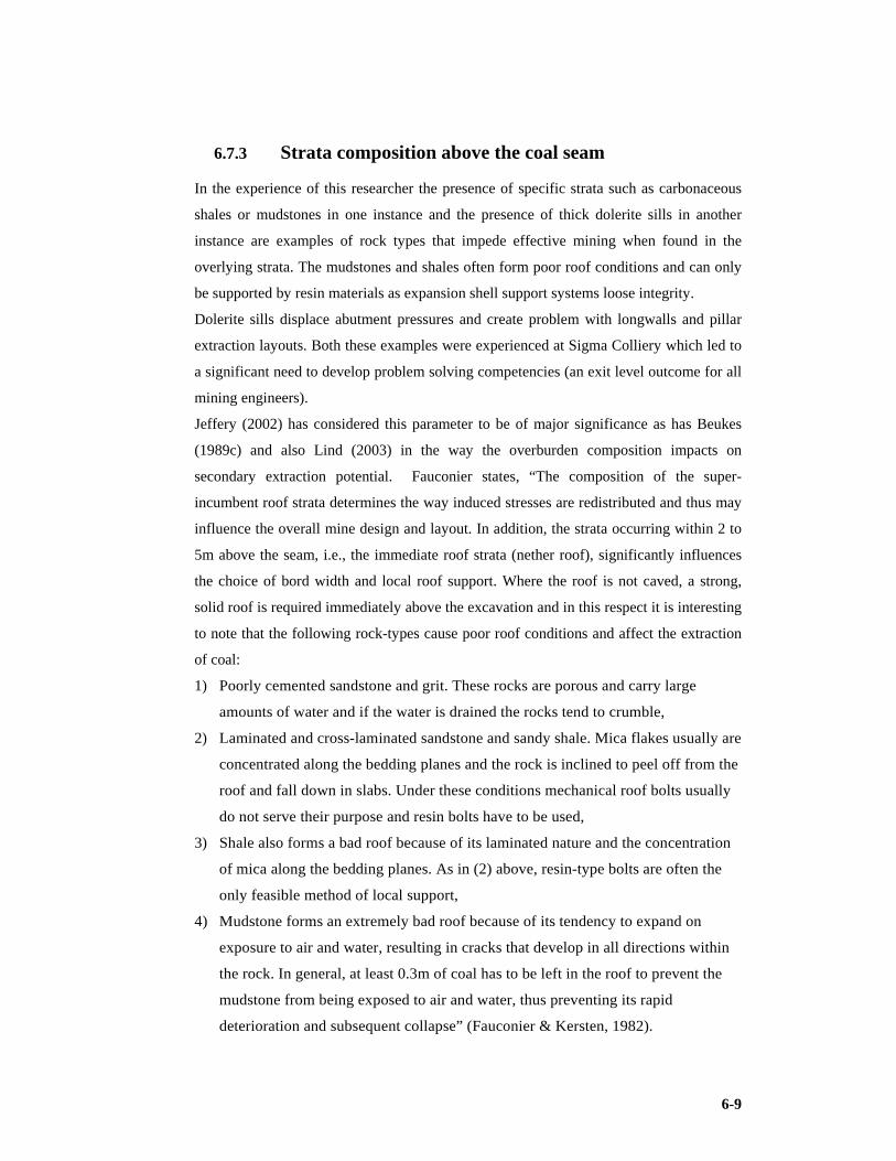
6-9
6.7.3 Strata composition above the coal seam
In the experience of this researcher the presence of specific strata such as carbonaceous
shales or mudstones in one instance and the presence of thick dolerite sills in another
instance are examples of rock types that impede effective mining when found in the
overlying strata. The mudstones and shales often form poor roof conditions and can only
be supported by resin materials as expansion shell support systems loose integrity.
Dolerite sills displace abutment pressures and create problem with longwalls and pillar
extraction layouts. Both these examples were experienced at Sigma Colliery which led to
a significant need to develop problem solving competencies (an exit level outcome for all
mining engineers).
Jeffery (2002) has considered this parameter to be of major significance as has Beukes
(1989c) and also Lind (2003) in the way the overburden composition impacts on
secondary extraction potential. Fauconier states, “The composition of the super-
incumbent roof strata determines the way induced stresses are redistributed and thus may
influence the overall mine design and layout. In addition, the strata occurring within 2 to
5m above the seam, i.e., the immediate roof strata (nether roof), significantly influences
the choice of bord width and local roof support. Where the roof is not caved, a strong,
solid roof is required immediately above the excavation and in this respect it is interesting
to note that the following rock-types cause poor roof conditions and affect the extraction
of coal:
1) Poorly cemented sandstone and grit. These rocks are porous and carry large
amounts of water and if the water is drained the rocks tend to crumble,
2) Laminated and cross-laminated sandstone and sandy shale. Mica flakes usually are
concentrated along the bedding planes and the rock is inclined to peel off from the
roof and fall down in slabs. Under these conditions mechanical roof bolts usually
do not serve their purpose and resin bolts have to be used,
3) Shale also forms a bad roof because of its laminated nature and the concentration
of mica along the bedding planes. As in (2) above, resin-type bolts are often the
only feasible method of local support,
4) Mudstone forms an extremely bad roof because of its tendency to expand on
exposure to air and water, resulting in cracks that develop in all directions within
the rock. In general, at least 0.3m of coal has to be left in the roof to prevent the
mudstone from being exposed to air and water, thus preventing its rapid
deterioration and subsequent collapse” (Fauconier & Kersten, 1982).

6-10
6.7.4 In-seam partings
To quote Fauconier and Kersten (1982), “Whether a non-coal parting in a coal seam can
be mined together with the seam, or whether only the coal above or below the parting can
be mined, depends on the following factors:
1) The thickness of the parting.
2) The composition of the parting.
3) The mining method.
4) The availability or non-availability of a beneficiation plant.
5) The difference in quality of coal above and below the parting.
6) The thickness of the coal above and below the parting.
The contaminating effect of the parting on the coal quality always is a critical factor when
raw coal is marketed, but it also affects the washing plant yield seriously where a washed
product is to be marketed, thus affecting the cost of the final product and, therefore, the
economics of the overall operation. The existence of in-seam partings present a practical
problem where coal is won by machine cutting methods in as much as such partings
usually have an extremely detrimental effect on pick-life, and therefore on the total cost
per ton mined” (Fauconier & Kersten, 1982).
The quality parameter often required by power utilities is the reduction of abrasiveness of
the injected material. Many systems have been developed for example the CAVITY
control process in the surface mining application at Middelburg Mines. The intent of this
management process is to control contamination that would increase the presence of
abrasive materials such as Silica in the pulverised coal. The major source of these
contaminants lies in the in seam partings and in certain instances the lenses of inorganic
rocks that are present in the seam horizon.
6.7.5 Vertical and lateral quality variations
Buchan wrote “In general, the best coal quality is found in the lower part of a coal seam
with contamination by dirt bands increasing towards the top. At the bottom of the seam,
however, a band of coal with interbedded shale and sandstone bands also may occur. It
happens often that the best horizon within a coal seam has to be selected in the mining
process in order to meet the quality parameters of the specific customer, and in the
process, coal, which could be utilised for other purposes', is left behind, thus affecting the
overall utilisation of the available reserves. Substantial lateral quality variations of a coal
seam often occur within a mining property and it may happen that certain reserve areas

6-11
will remain intact because the quality does not meet the specifications of the customer”
(Buchan et al, 1981).
6.7.6 Variations in seam thickness
Fauconier and Kersten (1982) noted that “A fluctuating thickness must by nature be very
disruptive to the mining method especially if the height of equipment to seam thickness
ratio is approaching one. “Coal losses may occur in areas where large variations in seam
thickness occur while the available equipment can operate only within a specific designed
height range. In some instances coal may be left in the roof or floor because of excessive
seam height, ranging beyond the maximum height capabilities of the existing equipment,
while in other instance reserves may remain sterilised because seams thin out to a point
where existing equipment cannot enter the excavations.
Some types of equipment, for example longwall equipment, are more vulnerable to seam
height variations than other types of equipment, and excessive seam height variations in a
particular field may preclude the application of such types of equipment, and therefore
the application of such mining methods” (Fauconier & Kersten, 1982).
6.7.7 Floor conditions
Fauconier argued “In highly mechanised mines the heavy mechanised equipment may tend to
pulverise soft, brittle rocks, causing the formation of dust and an uneven floor. In the case
of longwall mining such weak floor strata could affect adversely the functioning of the
advancing powered supports. Certain sediments are inclined to pulverisation especially
mudstones and shales.
Micaceous rocks, as well as certain types of shale and mudstone containing clay minerals,
tend to be slippery, thus impairing the effective functioning of mechanised equipment.
Dull coal often forms a better floor than the abovementioned rocks, in which case one
may, from practical considerations, be forced to sacrifice some coal in the floor in order
to improve the mining conditions. This practice, once again, adversely affects the overall
percentage extraction of the available reserves” (Fauconier & Kersten, 1982).
6.7.8 Water-bearing strata
Buchan reported, “Where the roof strata in the immediate vicinity of the underground
excavations contain water-bearing layers, such water could lead to local cracks in the

6-12
roof, local collapses of the roof, and nuisance water in the workings. Where caving
methods are applied, the influx of water from such water bearing strata may become a
major problem and great expense may have to be incurred to handle the water without
impairing the mining operations” (Buchan et al, 1981).
6.8 Geotechnical Factors Associated with the Choice of
Mining Method
Recent research (Jeffery, 2002) suggests that most Witbank coalfield collieries will close
during the 2020’s unless the pillar coal is exploited. Successful re-mining of these pillars
will heavily depend on understanding the roles geotechnical factors play in the
developing strategies to ameliorate their effects.
It must be noted that, Jeffery finds, that the selection of a secondary extraction method is
therefore most strongly affected by stratigraphy and the primary mining parameters.
Jeffery ranked and identified the factors, which impact on underground secondary
extraction, in major, moderate and minor categories. A ranking of 1 is the most important
or highest ranked. The work by Jeffery (2002) has been systematically discussed in
Chapter 2. Jeffery identified numerous geotechnical factors that impact on secondary coal
extraction to varying degrees.
6.9 Explosion Hazards
Cook (1999) has shown that goaf methane conditions are not as they are commonly
believed to be. Cook has been discussed in Chapter 2.
Phillips in Cook, 1999 has concluded that the proof of causes is very difficult to identify
precisely.
This researcher has had experience with the tube bundle telemetric system during mine
fire applications and the subsequent data use for Graham’s ratio analysis and Coward’s
triangle ‘propensity to explode’ determination. The equipment appears reliable.
Landman (1992) studied the South African coal mine explosion statistics and concluded
that the explosion hazard had increased. This work was also discussed in Chapter 2 and
will not be repeated here.
This researcher considers the understanding of methane behaviour in goafs and the effect
of coal dust in the general mining working place when hybrid mixed with methane to be

6-13
critically important to the safety of high extraction operations. Explosions are immense
killers and in the spirit of zero harm need to be eliminated or at least mitigated and must
be of paramount importance on the operators list.
6.10 Spontaneous Combustion
Fauconier and Kersten (1982) reports that, “Two mining areas in South Africa are
particularly liable to occurrences of spontaneous combustion, namely, the Vaal Basin and
the Klip River coalfield in Natal. In selecting a mining method for these areas, it is
important that full cognisance be taken at all times of the possibility of spontaneous
combustion. This phenomenon may preclude the application of certain mining methods or
it may necessitate the introduction of special measures to detect and control the
spontaneous combustion. Unfortunately this phenomenon often precludes or hampers the
application of higher extraction methods, based on roof caving principles (e.g. pillar
extraction, etc.) especially in thick seam areas where coal has been left in the roof, thus
forming part of the goaf” (Fauconier & Kersten, 1982).
It is fortunate in South Africa that flammable gas emissivity levels are not has high as
certain Australian incidents as this aggravates the spontaneous combustion risk in that
explosions may accompany the situation.
6.11 Surface Protection
As a general principle it can be accepted that when higher extraction rates of coal are
pursued and when caving methods are applied as a result, the surface overlying such
workings will be disturbed or damaged to some extent.
In current practice, the formula of D/2.7 (D = depth) is used to calculate the size of a solid
pillar that must be left for the protection of surface structures. The blanket application of
this formula under certain circumstances could have an unnecessarily detrimental effect
on the mineable reserves in the country, and it is advocated that some refinement be
introduced into the statutory protection of surface structures in order to minimize the loss
of mineable reserves. Already D/2.7 is a concession as the regulations require a horizontal
distance of 100m between workings and the unit to be protected.
Fauconier commented, “Ideally, from a reserve utilisation point of view, the mineral
rights owner should weigh up the cost of locking up certain reserves against the cost of
repairing damage to land or surface structures caused by mining operations. This is,

6-14
unfortunately, a one-sided view of the problem as many structures warrant protection and
large coal reserves often are overlain by valuable agricultural land of strategic importance
to the country. Despite the fact that it is settled in law that the mineral rights holder is
obliged to provide support for the soil of the landowner and lateral support for the soil of
adjacent landowners so as to avoid damage to the surface, and despite the fact that the
landowner is obliged to allow the mineral rights holder to do all that is necessary for the
reasonable exercise of his rights, grey areas still develop that defy easy solutions or easy
settlements. Although our courts have adopted the approach that, in the case of
irreconcilable conflict, the rights of the landowner must be subordinate to the rights of the
mineral rights holder, the problem of surface protection remains complex from a legal,
moral, economic, and strategic point of view. In addition to the abovementioned
complexities, the mineral rights holder often is without any choice as regards the
improved extraction of his available reserves owing to the fact that the application of the
Mine Health and Safety Act and regulations (MHSA), often precludes the efficient
mining of reserves under certain surface structures, which enjoy statutory protection from
damage by mining” (Fauconier & Kersten, 1982). Note the applicable legislation at the
time of Fauconier’s findings was the Mines and Works Act and has since been replaced
by the MHSA.
The desire to protect the surface may be taken to extremes in certain circumstances. An
example is the attitude of the Botswana Chief Engineer when there is a risk of any
subsidence occurring. Hence restrictions such as not allowing secondary pillar extraction
processes or the desire not to allow any road undermining even at significant safety
factors has resulted. The lowest safety factor that may be tolerated in pillar mining is
often 1.8 and with reluctance do they allow trail panels to prove the effectiveness and
safety of lower safety factors such as 1.6 or 1.4.
6.12 Technology Factors
Technology has progressed through an enormous evolution during the past two to three
decades with machine development and computer automation integrated. Available
technology currently may impose restrictions on the reserves that may be regarded as
mineable in future, particularly in the case of very thick seams or in the case of reserves
that are very disturbed geologically (e.g. faults and dykes).
“Technology, as applied to mining, has improved dramatically over the past two decades
and can be expected to improve even further in the future. The detrimental effect of

6-15
inadequate technology on the extractable reserves, therefore, will be mitigated to some
extent by technological developments in the future. There always will be room for
improvement and technological research and development will have to continue unabated
in the future in the interest of improved extraction by underground mining methods”
(Buchan et al, 1981).
6.13 Economic Factors
One of the mining engineer’s most significant challenges is forecasting the correct
technical economic model for the design application. The following parameters have a
major influence on this model. Buchan and the supporting team identified in sections
6.13.1 to 6.13.8:
6.13.1 Market considerations
“Several factors in the coal market, both export and inland, may have profound influence
on the percentage of reserves ultimately extracted from a given reserve field. All of these
factors tend to impose restrictions on the coal that may be regarded as saleable and hence
on the ultimate extraction of the reserves” (Buchan et al, 1981).
6.13.2 Price of coal
Concerning the price of coal Buchan reported, “If the overall price structure of coal is
relatively low, it is obvious that one of two things will happen: only the 'easiest' coal will
be mined (e.g. shallow deposits, thick seam areas, undisturbed blocks, etc.), leaving the
'difficult' coal behind, or selective mining will take place to mine the high-grade coal for
which a reasonable price may be obtainable, thus leaving the low-grade reserves behind.
Current export prices are such that marginal expansions of existing operations have
become attractive and that certain green fields have become viable propositions. The
price structure of inland coal, on the other hand, currently is such that even marginal
expansion of existing operations has become unattractive and the development of new
mines has become impossible.
As the economic viability of any coal mining venture depends on the price obtainable for
the saleable product, this factor may lead to a practice where the eyes of the reserves are
picked', resulting in a significant loss of potentially saleable reserves in the interest of
economic viability of the overall operation. Furthermore, the price of coal, as a major

6-16
determinant of economic viability, may preclude the application of certain types of
equipment and, therefore, certain high-extraction mining methods, thus affecting the
optimal extraction of available reserves” (Buchan et al, 1981). Currently (2009)
metallurgical grade coking coal fetches $250/t and inland power station thermal
ZAR120/t.
6.13.3 Quality requirements
“Quality requirements laid down by customers very often dictate which coal in a field
may be mined and which coal may have to be left in the ground. Fauconier stated, “As a
general proposition on commercial mines, the higher the quality requirements of the final
product, the lower the overall plant yield that will be obtainable from a given run-of-mine
product or the more selective the mining has to be to meet the necessary quality
requirements. In other words, reserve losses occur in one of two ways: part of the reserve
is discarded as a washing plant waste product or part of the reserve may be left unmined
owing to poor quality. Both these problems could be solved to some extent if markets
could be developed for low quality coal, for example, power generation by means of
fluidised bed combustion. Alternatively joint development of reserve fields for
commercial and power generation purposes also may offer some solution as much as a
high-grade product could be creamed off for commercial markets while the discards or a
middling product could be used for power generation, thus optimising the utilisation of
the total reserves” (Fauconier et al, 1982).
“The need for strict quality control often will preclude the application of certain mining
methods such as longwalling, leading to a further reduction in the extraction of available
reserves” (Buchan et al, 1981).
Blending opportunities are enhanced when multiple and more flexible sections or
production faces and localities are employed. This may not be possible with a single wall
unit.
6.13.4 Size grading
Buchan et al (1981) states, “The size grading of the final product required in the market
does not have a direct bearing on the total reserve picture but may have an indirect
bearing in as much as it may impose a restriction on the type of mining equipment that
may be used for the extraction of coal.

6-17
Where the market requires a fairly large product, this requirement may preclude the use
of continuous miners, which usually generate a large percentage of fines in the mined
product. This restriction on the type of equipment ultimately may manifest itself in a
reduced percentage extraction, although it is unlikely that this will be so under normal
circumstances” (Buchan et al, 1981).
6.13.5 Size of reserve
“Where a reserve block of limited dimensions is isolated from any other major reserve,
economic considerations may render such reserve unmineable. Economics, therefore,
may exclude such reserves from the potentially mineable reserves in this country”
(Buchan et al, 1981). The MPRDA (The Mineral and Petroleum Resources Development
Act) has empowered junior miners and historically disadvantaged South Africans
(HDSA’s) through the attainment of new order rights on these blocks of limited
dimensions. This was effective from 2007.
6.13.6 Capital
“The availability and the cost of capital probably are the two most important non-
technical determinants of the mining method that will be used ultimately in a given
reserve field, inasmuch as these considerations will determine whether low-capital,
labour-intensive systems or capital-intensive systems are chosen. This has a direct
bearing on the mining method employed and, therefore an indirect bearing on the ultimate
extraction of reserves as high extraction methods more often than not depend on capital-
intensive technological systems.
Although, under the present tax structure, capital expenditure may be written off for tax
purposes in the year in which it is incurred, and unredeemed capital expenditure may be
carried forward to successive years until completely written off, this often does not assist
the small operator if he cannot reflect this in another company already making a profit
and therefore he may have to go to a less capital-intensive and possibly less viable
system.
This problem may be circumvented to a certain extent by starting off with a less capital-
intensive system and utilising the cash flow generated by the operation to progress to a
more capital-intensive system and a higher extraction rate. The basic premise, however,
still remains: the availability and cost of capital may preclude the application of certain

6-18
methods, be it in the short term or over the life of the reserve field, and thus have a
bearing on the final percentage extraction of that field” (Buchan et al, 1981).
A problematic situation for southern African collieries is the differential in exchange rates
and the burden it places on imported equipment.
6.13.7 Labour
Buchan et al (1981) stated, “In South Africa there exists the seemingly irreconcilable
dichotomous situation where a shortage of skilled labour is occurring simultaneously with
unemployment in the lower skilled echelons.
Under these circumstances, it may be well to keep in mind that mechanisation and
automation may be technically desirable in certain circumstances, but it may adversely
affect unemployment, while at the same time it may be unproductive owing to the non-
availability of workers skilled enough to maintain the intricate equipment. Socio-political
considerations may well dictate the ultimate mining method and, therefore, the ultimate
extraction of available reserves. Under certain conditions, such as at great depths and in
very narrow seams, mechanisation may be the only viable way of extracting the coal at all
and sociological considerations may have to be left in abeyance, or, at the most, be
reduced to a lower priority rating” (Buchan et al, 1981).
It is interesting to note that the labour problem has a geographical connotation in as much
as skilled employees usually are more readily available near industrial areas while
unskilled labour usually is more readily available in rural areas. This would imply that
mechanisation may be more difficult to introduce in remote areas as the installation and
maintenance of sophisticated equipment may become very difficult owing to the shortage
of skilled labour. Training facilities then would become of more importance and would
have to be more elaborate and more sophisticated (Dougall et al, 2009).
6.13.8 Availability of equipment
“The availability of equipment for certain mining methods, to a certain extent, may assist
or preclude the introduction of these methods. If equipment is available ‘off the shelf’ this
factor becomes irrelevant, but if the equipment is difficult to come by, such difficulties
may preclude the introduction of those mining methods (Buchan et al, 1981). Some lead
times to acquire this equipment are as long as 18 to 24 months. This could have a
peripheral effect on the ultimate extraction of reserves if such equipment is synonymous
with higher extraction methods (Dougall et al, 2009). This report was the FS report

6-19
developed in conjunction with SRK’s Naismith (Rock Technical Engineer), van Vuuren
(Mining Engineer & Modeller), van Heerden (Geologist) and Millenovic (Hydrologist),
with this researcher as Lead Mining Engineer and Project Manager.
The process defined by Fauconier which was originally developed by Buchan and others
and presented in the 1981 Vacation School is widely accepted as a due diligent approach
to method selection but in practice a process which weights certain factors or elements is
often used as is displayed in the following case study.
6.14 A Case Study Dealing with a Methodology Developed to Make a Choice for a Pre-Feasibility Study
6.14.1 Introduction
A key consideration for the pre-feasibility study of the Morupule coal deposit is
evaluating alternative methods appropriate to the mining of the Morupule deposit.
Although the physical dimensions indicate an extensive resource (+8m wide),
geotechnical constraints limit the use of ‘full seam’ extraction techniques. Botswana
legislation currently poses restrictions on the safety factor that can be applied in a bord
and pillar mining environment which further restricts the extraction methodology.
This report discusses the approach the Project Team adopted in determining which
mining methods to consider for the Morupule coal deposit. The approach, methodology,
weighting factors and selection process are documented. The report concludes with a
recommendation for alternative methods to be considered in more detail during as part of
the pre-feasibility study (Prinsloo et al, 2008). This researcher was the Lead Mining
Engineer during the PFS conducted by DRA with Henk Prinsloo as Project Manager. The
PFS report is Prinsloo et al (2008). The selection method does not exclude the factors
mention and developed by Buchan et al (1981). It however displays a matrix which
assists the decision making process. When the geology and the economic conditions are
considered within a time frame that allows the application of a specific technology then
the decision is directed to a trade off of method options that are reduced in number.
Historic and available skill levels in that area may become an important factor in the
decision mix. The Buchan process is included in the DRA or Prinsloo et al, (2008) mix.

6-20
6.14.2 Approach
DRA developed an approach which was adopted during a decision making or mining
method selection session. Refer to Figure 6.1.
6.14.3 Mining methods considered
The mining methods considered were:
Drill and Blast with secondary bottom coaling, CM & Scoops, CM & Shuttle Cars, CM &
Continuous haulage (CH), Shortwall, Magatar Mining System, Longwall, Longwall with
rear Armoured Face/Flexible Conveyor (AFC) and Opencast.
Although all of the methods listed can be applied to the Morupule coal deposit, there are
mitigating factors which eliminates some of the methods.
6.14.4 Decision criteria
To select an appropriate mining method, consideration was given to:
1) Factors influenced by the mining method (such as the environment), and
2) Factors influencing the mining method (such as skills, availability, etc).
The description is a ‘definition’ that has been applied when assessing the impact on a
particular method. The weighting is based on the criticality of success of the method. It is
a subjective value of 1, 2 or 3 assigned to the criteria:
1) 1 implies not critical.
2) 2 implies influential.
3) 3 implies critical.
For example:
1) Selectivity (1) i.e. how selective the method is to change in mining horizon, variation
in mining height and coal quality, is deemed less critical than the Flexibility.
2) Flexibility (2) of the method i.e. the ability of the method to adapt to changing
conditions such as geology, method of extraction, direction of mining etc. In
comparison,
3) Production rate (3) i.e. the ability of the method to produce the desired tonnage on a
sustainable basis is deemed more critical than either of other two criteria mentioned.
The assessment required each mining be assessed against criteria outlined. For this
purpose, a scoring system of 1, 3 and 5 was used. Particular criteria such as development,

6-21
skills, impact of change and lead time to implementation have a different scoring system
due to the nature of the criteria (Prinsloo et al, 2008). Table 6.5 summarises this.
DRA Approach to Method Selection Figure 6-1
Figure 6-1 Approach to method selection (after Prinsloo, 2008)
Table 6-1 defines decision criteria and Table 6-2 scoring criteria. Table 6-3 summarises
methods eliminated and 6-4 displays the selection matrix.
6.14.5 Assessment As mentioned in section 6.14.3, there are mitigating factors which led to the elimination
of some of the methods prior to the selection process. Table 6.6 summarises the methods
eliminated with supporting comments (Prinsloo et al, 2008).
6.14.6 Results The mining methods subjected to the evaluation were:
1) Conventional drilling and blasting (DB in Table 6.4).
2) Continuous miner with shuttle cars (CM &SC).
3) Continuous miners with scoops (CM & SCOOP).
4) Mechanised Short wall (S/Wall).

6-22
5) Continuous miners with continuous haulage (CM &CH).
Table 6-1 Decision criteria used during the evaluation (after Prinsloo, 2008).
Criteria Description Weight
Production rate Ability to produce desired tonnage on a sustainable basis 3
Flexibility Ability of the method to adapt to changing conditions (geology, method,
direction etc) 2
Extraction Influence of method on extraction ratios (primary & secondary) 3
Influence of geology Influence of geological conditions (dip, faults, dykes, seam thickness) on
production 3
Influence of floor Influence of floor conditions (softness, contamination) on production 3
Operating costs General operating cost ratings 2
Capital Costs General capital cost ratings 2
Safety The method is inherently safe. What other factors influence safety 3
Environmental Impact The influence of the method on the environment 2
Selectivity How selective is the method (changing of mining horizon, variation in mining
height coal quality) 1
Continuity of production How is production influenced if any of the non- coal getting equipment stops
(excl conveyors) 2
Ventilation required Are there any significant ventilation requirements 1
Proven technology Has method been proved ( in Southern African conditions) 3
Ancillary equipment Is a significant amount of auxiliary equipment required (LHD's, chock carriers,
special spares, etc) 1
Development Does the method need other methods to carry out development (1=Yes, 5=No) 1
Skills personnel General skills of the production and planning (5=Low skills, 1= High skills) 3
Impact of change (0 High; 5 Low) 3
Lead time to
implementation Lead times (+12 m=0;12m=3;<12m=5) 3
The scoring was obtained by consensus decision from the project team members
participating in the discussion. Table 6.7 summarises the results. The results of the
evaluation rank the methods as:
1) Conventional drilling and blasting 153
2) Continuous miners with shuttle cars 151
3) Continuous miners with LHD’s 145
4) Shortwall mining 101
5) Continuous miners with continuous haulage. 95
This was the methodology employed in actual design project in which the researcher was
part of the DRA / SRK Consulting project team during 2008.
It should be noted that the significant parameters of geology, technology and economics
are not excluded but may be implicit in some of the concepts.
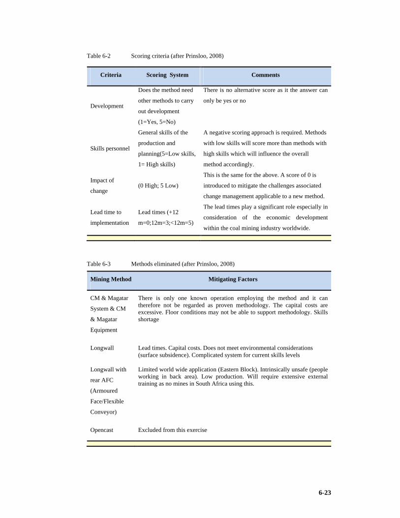
6-23
Table 6-2 Scoring criteria (after Prinsloo, 2008)
Criteria Scoring System Comments
Development
Does the method need
other methods to carry
out development
(1=Yes, 5=No)
There is no alternative score as it the answer can
only be yes or no
Skills personnel
General skills of the
production and
planning(5=Low skills,
1= High skills)
A negative scoring approach is required. Methods
with low skills will score more than methods with
high skills which will influence the overall
method accordingly.
Impact of
change (0 High; 5 Low)
This is the same for the above. A score of 0 is
introduced to mitigate the challenges associated
change management applicable to a new method.
Lead time to
implementation
Lead times (+12
m=0;12m=3;<12m=5)
The lead times play a significant role especially in
consideration of the economic development
within the coal mining industry worldwide.
Table 6-3 Methods eliminated (after Prinsloo, 2008)
Mining Method Mitigating Factors
CM & Magatar
System & CM
& Magatar
Equipment
There is only one known operation employing the method and it can therefore not be regarded as proven methodology. The capital costs are excessive. Floor conditions may not be able to support methodology. Skills shortage
Longwall Lead times. Capital costs. Does not meet environmental considerations (surface subsidence). Complicated system for current skills levels
Longwall with
rear AFC
(Armoured
Face/Flexible
Conveyor)
Limited world wide application (Eastern Block). Intrinsically unsafe (people working in back area). Low production. Will require extensive external training as no mines in South Africa using this.
Opencast Excluded from this exercise

6-24
Table 6-4 Selection matrix (after Prinsloo, 2008)
Criteria Weight DB CM CM & S/W CM & Production Rate 3 3 5 5 5 5 Flexibility 2 5 5 5 1 3
Extraction 3 1 5 5 5 1
Influence of Geology 3 5 3 3 1 1
Influence of Floor 3 5 3 3 1 1
Operating Costs 2 1 3 3 5 1
Capital Costs 2 3 3 3 1 1
Safety 3 1 3 3 5 3
Selectivity 1 5 5 5 1 5
Continuity of Production 2 5 3 3 5 5
Ventilation Requirement 1 1 3 3 3 3
Proved Method 3 5 5 5 5 5
Ancillary Equipment 1 3 1 1 1 1
Development (1=yes; 5=no) 1 5 5 5 1 5
Skills (5 low; 1 high) 3 5 1 1 1 1
Impact of Change (0 high; 5 low) 3 5 5 3 0 0
Lead Times (+12months=0; 12=3; <12=5) 3 5 3 3 0 0
Environment 2 3 5 5 1 5
No single correct answer exists and only a careful marriage of technological, sociological,
and economic considerations ultimately can lead to increased extraction of coal by
underground methods (Prinsloo et al, 2008).
6.15 Conclusions
1) Factors specifically considered as endorsed by leading consultants include:
Production rate; Flexibility; Extraction; Influence of geology; Influence of floor;
Operating costs; Capital costs; Safety; Environmental impact; Selectivity;
Continuity of production; Ventilation required; Proven technology; Ancillary
equipment; Development; Skills of personnel; Impact of change; Lead time to
implementation.
2) As was seen in this chapter, a multitude of systems, methods, and equipment
exist from which endless combinations and permutations may be selected. In
making a choice of methods and/or equipment, careful consideration should be
given to all the factors influencing such a choice in order to arrive at an optimal
combination of methods and equipment, which will ensure the best utilisation of
resources
7-1
7 CLASSIFICATION OF METHODS AND THE IMPACT OF MINING HEIGHT
So far this research has addressed the objectives and research design, it has built
awareness of relevant literature and studied the geology, hydrogeology and rock
engineering that would have influence on the best practice systems. It has considered the
case study implementation of the process at Morupule Colliery. It has identified the
factors that influence the selection or choice process in determining which mining method
to use or apply. It can now take a closer look at thick and thin seam mining respectively
(the mining profile) before identifying some best practice methods. The mining height is
generally not a controllable but in certain cases may be, mostly the mine is forced to
exploit the available resource. It is evident when analysing production results that the
higher production rates come from the thicker seams, however the challenge lies in
percentage extraction. The percentage tends to decline in thick seams.
7.1 System of Classifying Mining Methods
Most systems of classifying mining methods are based on methods of supporting the roof
strata. These methods take into account three forms of support – natural (pillars), artificial
(fill) and none (caving). The essential features to be considered are the relations between
the method of working, the key orebody (seam) properties defining the applicability of
that method and the country rock mass properties that are essential to sustain the method
Brady & Brown (1983) in (Beukes, 1989a).
Figure 7.1 shows one version of a common approach to underground mining method
classification which has been modified to include thick seam coal mining methods. Not
all methods of mining currently employed throughout the world are shown on this
diagram but they could be added if required. The unsupported or caving methods seek to
induce failure of, and large displacements in, the country rock. At the other end of the
spectrum, the supported methods seek to maintain the integrity of the country rock and to
strictly limit its displacement.

7-2
Classification of UG Mining Methods Figure 7-1
Figure 7-1 Classification of underground mining methods (after Galvin 1981)
As shown in Table 7.1, the unsupported or caving methods include sublevel caving and
drawing, pillar extraction and longwall. In the longwall method, the coal is extracted
mechanically and the overlying strata cave under the influence of gravity and
redistributed stresses. In the sublevel caving and drawing method, a slot is developed
through the total seam thickness and slices of coal are sequentially blasted into this slot,
the coal is then drawn from draw points in the footwall. In the Pillar Extraction methods
pillars are reduced to fenders and snooks or completely removed.
Thick seam mining methods are classified under one of the following three types of
mining systems: full face; slicing; and caving and drawing. This system of classification
is still very broad so an additional criterion, namely, roof strata control has to be
introduced. Mining methods may: preserve the integrity of the roof strata; result in
limited subsidence of the roof strata; or cave the roof strata. Roof strata control is a very
relevant criterion since it often determines whether a mining method is suited to a
particular set of conditions. By combining the three types of mining systems and the three
types of roof strata control, nine classes of thick seam mining methods can be identified.
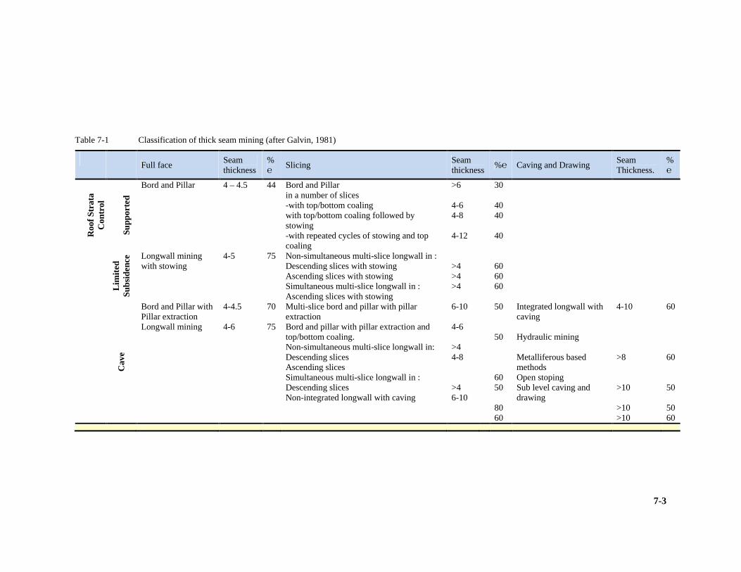
7-3
Table 7-1 Classification of thick seam mining (after Galvin, 1981)
Full face
Seam thickness
%℮
Slicing Seam thickness
%℮ Caving and Drawing Seam Thickness.
%℮
R
oof S
trat
a C
ontr
ol
S
uppo
rted
Bord and Pillar
4 – 4.5
44
Bord and Pillar in a number of slices -with top/bottom coaling with top/bottom coaling followed by stowing -with repeated cycles of stowing and top coaling
>6 4-6 4-8 4-12
30 40 40 40
Lim
ited
Sub
side
nce Longwall mining
with stowing 4-5 75 Non-simultaneous multi-slice longwall in :
Descending slices with stowing Ascending slices with stowing Simultaneous multi-slice longwall in : Ascending slices with stowing
>4 >4 >4
60 60 60
Cav
e
Bord and Pillar with Pillar extraction Longwall mining
4-4.5 4-6
70 75
Multi-slice bord and pillar with pillar extraction Bord and pillar with pillar extraction and top/bottom coaling. Non-simultaneous multi-slice longwall in: Descending slices Ascending slices Simultaneous multi-slice longwall in : Descending slices Non-integrated longwall with caving
6-10 4-6 >4 4-8 >4 6-10
50 50 60 50 80 60
Integrated longwall with caving Hydraulic mining Metalliferous based methods Open stoping Sub level caving and drawing
4-10 >8 >10 >10 >10
60 60 50 50 60

7-4
The total mining height is extracted in each stage of the mining operation. Methods such
as single pass longwall mining are single stage operations, while bord and pillar mining
with pillar extraction is a multiple stage operation.
These systems have technical, equipment and operational limits at a height of 6m. They
are generally confined to countries with a high level of mining technology (Galvin et al,
1981).
Wall faces of mining height up to 8m are currently (2009) under development by OEMs
(original equipment manufacturers). To prevent strata control problems they need to
ensure rapid face advance.
7.1.1 Slicing
The total mining height is extracted sequentially in slices, either starting from the bottom
or from the top. If the slices are mined concurrently, the term simultaneous is used to
describe the operation. There may be a time lapse between the mining of each slice, in
which case the operation is referred to as non-simultaneous (Galvin, 1981). ‘Bottom
coaling’ and ‘top coaling’ may be considered derivatives of slicing.
7.1.2 Caving and drawing
The total mining height is extracted by undercutting the seam and then caving the
overlying coal into this development, from where it is drawn off (Galvin, 1981). Wall
Mining (LW or SW), Pillar Extraction (PE) and Rib Pillar Extraction (RPE) are forms of
caving after the supporting seam has been exploited.
7.2 Major Underground Mining Systems
Seam thickness considerations need to followed by a focus on method (Bord & Pillar or
Wall) and the support strategy (Pillar, Yield Pillar or Caving).
When considering underground mining methods, it becomes clear that these methods can
be classified broadly into three systems, each with its own distinctive features:
1) A system where the roof is supported and where the surface is left virtually intact
and undisturbed,
2) A system where the roof and its overlying strata are caved in a controlled fashion
to fill the void caused by mining operations,

7-5
3) A system in which the roof is supported temporarily and in which the supports
may be allowed to fail in a stable, non-destructive fashion after mining operations
have ceased.
Bord and pillar mining is ideal for relatively shallow deposits where overlying rock
pressure is low. Seams are mined leaving in situ coal pillars, which are big enough to
support the roof indefinitely, and a chequer-board pattern of mined-out 'rooms'. This
method currently permits around 65% of the available coal to be extracted at depth less
than 100m below surface.
The adoption by several collieries of the 'squat-pillar' method developed by the now
defunct Chamber of Mines Research Organisation (COMRO), and approved by the
Government Mining Engineer (now Chief Inspector), will increase extraction rates -
especially at depth - through the employment in bord-and-pillar mining of smaller pillars
than were previously thought necessary.
When the overlying strata impose no restrictions, 'total-extraction' mining can take place
(though, in reality, somewhat less than 90% is recovered on average). There were two
major underground total extraction systems employed in South Africa namely, pillar
extraction and wall mining.
Pillar extraction requires the forming of a bord and pillar layout and the consequent
removal of all or partial amounts of the pillars on the retreat.
In rib pillar extraction, not really used currently, a continuous miner machine cuts a
roadway up to 1.5km in length through the coal and 5m in from the edge of the area to be
mined. This leaves a 5m wide band of coal in the form of a long, isolated rib pillar along
one side of the tunnel.
With the aid of timber or hydraulic props to hold up the now unstable roof, the continuous
miner cuts away the rib pillar in a series of curved cutting sweeps. The machine repeats
the cycle by mining into the remaining coal area, again cutting a tunnel and leaving a rib
pillar.
The other total extraction method employed is wall mining. Longwalls and shortwalls are
usually several hundred meters long and essentially consist of a corridor in which one
wall and the roof are formed by steel supports capable of resisting hundreds of tonnes of
pressure from the subsiding mine roof above. The second side of the corridor is formed of
coal and is the actual face from which coal is cut. A mechanical coal cutter, bearing two
large revolving shearing drums with steel picks, runs the whole length of the coal face on
rafts. This device is known as a shearer. This cuts into the coal and widens the corridor

7-6
during each sweep, thus advancing the coal face. The new coal falls on to a conveyor and
is drawn out of the longwall face (Fauconier & Kersten, 1982).
Hydraulic rams linked to the line of props push the conveyor and coal cutter forward into
the newly-mined-out space in the face. In turn, each hydraulic support is then released
from its position and hauls itself forward after the advancing face, reinstalling its steel
canopy against the recently exposed area of face roof. The increase exposed and
unsupported span behind and located in the goaf area then succumbs to gravitational back
break and caves.
7.2.1 Roof supporting methods
The roof and its super incumbent strata in any excavation can be prevented from caving
or collapsing in one of the following ways:
1) By leaving coal pillars in sufficient numbers and of adequate size in situ, i.e., bord
and pillar mining.
2) By introducing additional, artificial means of support in the excavated areas to
support the roof and the roof strata immediately after mining has taken place or while
mining is still in progress, e.g., ashfilling, matpacks, coalcrete, etc.
Pillar support
Bord and pillar mining has been, and still is, the best known and most widely practised
method of underground coal mining, in South Africa owing to its inherent safety, low
capital investment, and low operating cost.
Bord and pillar mining, involving several stages of either bottom or top coaling, has been
employed successfully in thin, medium, and thick seams, but results in a rapid decrease in
percentage extraction as seam thickness and/or depth of mining increase. It can be
concluded that, as deeper deposits are mined in the future, bord and pillar mining will
become progressively more wasteful in terms of available reserves.
The design of bord and pillar workings usually is in accordance with the well-known
Salomon graphs. The safety factor used usually depends on the ultimate plan of mining,
i.e., whether top or bottom coaling is contemplated (which will reduce the safety factor),
or whether pillar extraction will be carried out as a method of secondary extraction
(which will require a substantial safety factor on the primary extraction phase).
Artificial support
Artificial support usually is introduced where it is desirable to prevent the roof from
collapsing, but where the coal has been excavated to the extent that the remaining pillars

7-7
are insufficient to act as a permanent means of support. This usually occurs where the
safety factor is less than one.
Artificial support can be seen as a method of improving the percentage extraction of bord
and pillar mining. Where the seam is relatively narrow, matpacks may be employed to
supplement the support offered by small coal pillars. This method has been successfully
employed in Natal, particularly in handgot areas, where the rates of advance of some
faces permit the introduction, of matpacks as a means of systematic support. In thicker
seam areas, however, and in areas with rapid face advance, the logistic problems and
costs involved in the systematic installation of matpacks could become prohibitive, thus
excluding this method of support.
Fauconier reports, “An interesting project undertaken by the University of Kentucky in
the United States is a study on the use of coal refuse as a concrete aggregate with mining-
orientated applications. The mixture of raw refuse aggregate, Portland cement, and sand
is termed 'coalcrete' and it is envisaged that the coalcrete could be placed underground in
bord and pillar mines at a reasonable cost so that a substantial portion of the remaining
coal pillars could be extracted. One possible means of improving the percentage
extraction of bord and pillar mining in thick seam area is to fill the bords with fly ash
after completion of the primary cut. Fly ash resists the lateral expansion of the pillar and
provides confinement to the pillar sides, thereby strengthening the pillar. Apart from
increasing the strength of pillars and the stability of bord and pillar workings, ashfill also
can provide a suitable working platform during the top-coaling operation” (Fauconier &
Kersten, 1982).
7.2.2 Caving methods
It is accepted that methods that allow caving of the roof generally tend to give higher
extraction rates than methods that rely on part of the ore reserve as a means of support.
Owing to this notion these methods, quite incorrectly, through the years also have become
known as 'total extraction methods'. This is a misnomer as the extraction is very seldom,
if ever, total, even when viewed on an in-panel basis. These methods, with the exception
of sub-level caving, have been termed 'panel mining' methods. These roof caving methods
can be classified into four categories (Fauconier & Kersten, 1982):
1) Pillar extraction methods,
2) Longwall methods / shortwall methods,
3) Rib pillar extraction methods,
4) Sub-level caving methods.

7-8
Pillar Extraction Methods. Pillar extraction methods have been practised in South
Africa with a large measure of success, especially in handgot mines. Mechanised pillar
extraction have not been extremely successful in the country until 1980 when the
introduction of continuous miners to bord and pillar mining systems brought a new
dimension to the safety and efficiency of pillar extraction by mechanised methods.
Where pillar extraction is to be practised the accepted system is to leave large pillars
(with a safety factor of at least 1.8) during the primary development phase while
advancing. Once the panel development has been completed, the pillars are extracted
during the secondary phase of mining on the retreat. The pillar extraction line usually is
carried at an angle of 45° to the centreline of the panel.
In conventional mechanised pillar extraction, all of the pillars on the diagonal retreating
line are mined simultaneously, while in pillar extraction with continuous miners, the
pillars are extracted one pillar at a time. An in-panel extraction of about 85% to 95% is
usually obtainable via pillar extraction methods (Fauconier & Kersten, 1982).
The principles of pillar extraction, together with some examples of its application, will be
discussed in Chapter 8.
Longwall / Shortwall Methods. With longwall / shortwall mining methods the principle
is to extract all of the coal over the width of the panel face in successive slices or cuts,
with the roof being allowed to cave or goaf behind the supports.
The difference between longwall and shortwall mining lies in the equipment used, the
capital outlay required per panel, and the length of face.
Longwall mining can be practised as an advancing or a retreating system (although only
the latter currently is being used in South Africa) while shortwall mining is usually only
practised on the retreat.
As regards the equipment, longwall mining usually makes use of some type of shearer in
conjunction with an armoured face conveyor, while shortwall mining usually employs a
continuous miner with shuttle cars or with a continuous haulage system. (In South Africa
we refer to a short longwall as a shortwall, this is not the same as the traditional
shortwall). Both systems usually employ self-advancing, hydraulic-powered supports.
Rib pillar Extraction Methods. Rib pillar extraction refers to a series of methods that
can be regarded as a combination of pillar extraction and shortwall mining methods. The
term 'rib pillar' was coined in South Africa to describe a series of methods that are based
on the extraction of a rib of coal between development roads and the goaf, with a solid
block of coal (the unmined balance of the panel) providing the major means of support in
the workings. The origin of these methods, however, may be traced back to Australia.

7-9
Legislation in Australia up to the early 1950's prevented the mechanical extraction of
pillars, resulting in extensive areas of bord and pillar mining. When the law was changed,
extraction of pillars left in the initial mining operation, was carried out, using hand
mining systems and conventional mechanised equipment.
During the mid-50's, continuous miners were introduced to the Australian coal mining
industry. The need for multiple working places to maintain output was eliminated to a
large extent. Some new panel layouts emerged, but the actual extraction methods of
pillars still closely followed that of handgot operations.
In the early 60's, newly formed pillars were extracted by the 'open end lift' or 'split and
lift' method. The extraction rate remained low, however, because of operators leaving
'snooks' or failing to complete a lift, which adversely affected the operations and resulted
in high losses of coal, with large numbers of pillars being lost.
The Wongawilli method of extraction was then developed in an attempt to attain the
following objectives:
1) To provide a single working place.
2) To extract coal in a stress relieved area.
3) To utilize the coal seam as a major means of support during extraction operations.
4) To achieve 90 % in-panel extraction of working areas.
5) To provide a simple and easily understood system.
Many difficulties arose with the roof support in the variations of the Wongawilli system
and the Munmorah system of extraction was a further development of the Wongawilli
system in an attempt to overcome some of these difficulties.
In South Africa two experiments were conducted, using modified Wongawilli /
Munmorah methods. These experiments, one at Sigma Colliery, the other at Kriel
Colliery, proved the methods to be both feasible and safe.
Sub-level Caving Methods. Sub-level caving in coal mining usually is applied only in
coal seams where the nature of the coal seam excludes the practical application of other
coal mining methods, for example, steeply inclined coal seams.
The method basically consists of driving a series of sub-levels commencing at the top of
the ore body. A starting vertical slot is cut and then a series of ring patterns are drilled and
blasted, the broken coal being drawn off after each blast. As there currently are very
limited deposits of coal in South Africa that would be suitable for the application of sub-
level caving methods, however some application in the Waterberg is a possibility
(Fauconier & Kersten, 1982).

7-10
7.2.3 Yielding pillar methods
A novel method of designing bord and pillar workings, which has the theoretical potential
of improving percentage extraction, was proposed by Salamon (1970). This method,
which is known as the yielding pillar method, is based on the observation that the failure
of a coal pillar either can be stable or unstable, depending on the post-failure
characteristics of the pillar and the stiffness of the mining layout.
In terms of Salamon’s conditions, a pillar layout is perfectly stable if:
Equation 7-1 Stable Pillar layout as a function of stiffness of layout
where f is a suitably selected safety factor λm is the minimum slope of a force-displacement curve
of the pillar, and λc is the local stiffness of the mining layout.
It should be noted that the local stiffness, λc, is a function of the mining layout and the
super incumbent strata. In the case of an extensively mined out area supported by more or
less uniformly sized pillars λc = 0 and the only possible stable layout is one where the
strength of the pillars exceeds the load acting on them.
By sub-dividing the mining area into panels separated by indestructible barrier pillars, the
local stiffness is increased by decreasing the distance between barrier pillars. The local
stiffness also increases with depth.
Apart from increasing the local stiffness of the mining layout, the main function of barrier
pillars is to isolate the various parts of the mine and to ensure that any pillar collapse that
may occur is contained within one panel. The barriers can play this role effectively only if
their width to height ratio is large. It is more likely that these wide barriers will be
sufficiently strong to support the weight of the undermined overburden, even without the
assistance of small pillars within the panel. The role of the latter primarily is to maintain
the integrity of the roof between the barriers.
The most efficient use is made of panel pillars if they are designed in such a way that they
exert the maximum supporting action on the roof. This means that when the panels are
fully developed, the load on the panel pillars should be equal to their strength. Because of
the uncertainties concerning the strength of pillars and local variations in the strength of
coal seams, it is possible that the panel pillars will be in a failing state. Such an
eventuality can be tolerated only if the overall mining system is designed in such a
manner that the possibility of an uncontrolled collapse is excluded. It will be appreciated
fλm = λc

7-11
that the improved percentage extraction within a mining panel is negated partially by the
coal remaining in the barrier pillars. The bord width is normally of the order of 6m to
7m. The most notable result of this design study is that the introduction of barrier pillars
would result in a reduction in extraction at shallow depths.
Reduced Extraction Rate at Increased Depth When Using Pillars
Figure 7-2
Figure 7-2 Reduced extraction rate with increased depth when using pillars (after
Fauconier, 1982)
At the same time, considerable improvements in the exploitation of reserves could be
achieved at moderate and great depths with the aid of substantial barrier pillars.
7.2.4 Coal winning methods
Once a mining method has been chosen, consideration then should be given to the
breaking or winning of the coal. Here several options exist, namely, blasting methods,
machine cutting methods, and hydraulic mining methods. Of these three options the
former two are practised extensively in this country and elsewhere in the world, while the
third has only limited application under specific conditions (Fauconier & Kersten, 1982).
Blasting Methods
Blasting methods are older than coal mining itself in South Africa and are very well
known. To employ blasting methods, holes are drilled into the coal seam and the coal is
broken up by a blast that may be best described as a very rapid release of energy within
the drilled hole.
Generally explosives are used as a blasting agent, but where fragmentation is to be
controlled, air blasting has been used with some measure of success, but only on a limited
7-12
scale in this country (e.g. at Greenside Colliery). Where hard, abrasive interstitial layers
occur within coal seams and where numerous magmatic intrusions occur throughout the
reserve area this method remains the more successful method of winning coal.
As a rule blasting methods will not be employed on longwall or shortwall faces these
days, owing to the availability of suitable cutting equipment and because of the need for
an uninterrupted operation with a steady rate of face advance.
Fauconier stipulates that blasting methods, “do suffer from several disadvantages that
may render them unsuitable under certain circumstances, for example:
1) Shock-waves from the blast cause fragmentation of the immediate roof, sides, and
floor surrounding the excavation; this could lead to undesirable mining conditions
where the surrounding strata deteriorate easily as a result of the shock-waves,
2) The operations are not concentrated, leading to increased supervision
requirements and to decreased productivity of labour,
3) A large number of working faces are required to maintain productivity as blasting
methods rely on a series of discrete sequential operations, this is not always
possible, e.g. bord and pillar workings at great depths are limited in the number of
roads that may be employed in any panel,
4) Security risk. Where explosives are used as a blasting agent there is always the
security risk involved with explosives, safety.
5) Blasting operations are always associated with ascertain amount of danger, which
requires stringent measures to ensure the safety of the workers involved in the
blasting operation itself, and in the concomitant operations in that mining area”
(Fauconier & Kersten, 1982).
Machine Cutting Methods
Machine cutting methods invariably are more productive than blasting operations. For
certain mining methods such as longwall and shortwall mining, machines have become
the accepted way of winning coal, while for pillar extraction this method in the 1980’s
has proved to be an unqualified success in South Africa (e.g. at Usutu Collieries where
pillar extraction by means of continuous miners was standard practice as a method of
secondary extraction).
For other methods, such as bord and pillar development, the choice between machine
cutting methods and blasting methods is not very clear always, and in some instances size
distribution requirements of the final mined product may dictate the choice.

7-13
Fauconier states, “machine cutting methods also suffer from some inherent disadvantages
that may be ascribed to inadequate or insufficient technological development. Some of
these disadvantages are:
1) Height restrictions. Machines usually are limited to a certain height that can be
mined; for example, longwall mining is now moving into a phase where the
mining of 6m thick seams in one single lift is becoming technologically feasible,
while continuous miners generally are still limited to a maximum working height
of approximately 5m, taller mining machines to attain heights of 6m are developed
but not broadly implemented.
2) Geological disturbances. Faults and dykes present a serious problem with longwall
mining, but various approaches are being considered currently to overcome this
problem, e.g., by premining the dykes and refilling the cavity with a suitable material
before panel extraction commences. These ideas remain, as yet, relatively untried and
unproved but have great potential. Magma tic intrusions also present a big problem
with continuous mining but the latter type of mining is not as vulnerable in this
regard as longwall mining, bad roof conditions.
3) Although bad roof conditions affect all types of mining, the effect is more noticeable
where roof supporting methods, such as bord and pillar mining, are employed. This is
especially true where blasting methods are employed where shock waves from
blasting may augment the bad roof conditions, thus compounding the problem”
(Fauconier & Kersten, 1982).
Hydraulic Mining Methods
In European countries the winning of coal by means of pulsating high-pressure water jets
has gone beyond the experimental stage and today is a practical reality. Two of the most
well-known of these operations are the German Hansa Mine (now closed), which was
changed to a hydraulic mining and transportation system in 1977, and the Kaizer
Hydraulic Mine in Canada. The application of hydraulic mining seems to be favoured in
steeply bedded seams where it is impractical to mine the coal economically by other
methods. Its advantages seem to centre on increased safety for the operators and higher
production and productivity under the previously mentioned conditions. Furthermore, it is
eminently suitable to be combined with the hydraulic transportation of coal, which has
been shown to provide benefits in safety, efficiency, and cost, even where coal is won by
conventional mechanized methods. The hydraulic transportation of coal to the preparation
plant is an established and reasonably well-understood technique and is becoming
increasingly more popular for certain applications.

7-14
Fauconier reports “The coal deposits generally found in South Africa do not lend
themselves to this type of mining. This method probably will not find wide application, if
any, in this country” (Fauconier & Kersten, 1982).
7.3 Thick Seam Mining
7.3.1 Statistical background
Coal is South Africa’s primary source of energy. This coal comes from collieries ranging
in output from 100,000tpa to more than 10Mtpa. The number of operating collieries was
64 in 2004 and 73 in 2009. This is currently (2009) showing significant potential growth
due to the current coal price which ranges from R120/t for power station steam coal to
$250/t for metallurgical grade reductants. South Africa ranks as the fifth largest coal
producer (5th) in the world and the fourth largest exporter (4th) in 2009.
According to the Statistical Review of World Energy, there are approximately 28.6Bt
recoverable hard coal reserves in South Africa at present. This puts South Africa eighth in
the world in terms of recoverable coal reserves (8th) (BP Amoco , 2005).
About 51% of South African coal mining is underground and the rest is opencast. Of the
coal mined underground, some 90% is produced by bord and pillar (B&P), 5% by pillar
recovery (PE or RPE), and 5% by longwall mining (LW or SW) and other methods.
On the basis of reserve estimates of the Commission of Inquiry into the Coal Resources
of the Republic of South Africa (Petrick et al, 1975), thick seam reserves constitute over
50% of the country’s mineable coal reserves. Furthermore, these estimates indicated that
85% of these reserves can be extracted only by underground mining methods. Coal seams
between 4 and 6m thick represent just over 70% of the total thick seam reserves (DME ,
2006).
Although these estimates were conducted long ago, it is logical to assume that the
proportion of thick seam reserves to total reserves will remain the same provided that no
new reserves are discovered. Hence they are applicable within the context of this
research.
A resource of 37Bt has been inferred in Botswana (Minney, Personal communication,
2009).
Projects and associated developments are underway and planned in Mozambique’s
Zambezi coal basin and will ultimately turn it into one of the world’s major suppliers of
seaborne coking coal and in addition this basin will help to alleviate electricity generation
shortage in southern Africa (Mining Review, 2008).

7-15
7.3.2 Defining thick seams
Any discussion concerning thick seam mining has to begin by defining a thick seam. The
simplest way of defining a thick seam is to identify a critical seam thickness above which
a seam is said to be thick. Since volumetric extraction is influenced by the macro-
environment within which a colliery operates, the critical seam thickness varies from
country to country. A popular definition which is based on productivity considerations
states that “a thick seam is a seam which falls beyond a seam range in which maximum
face productivity can be achieved using existing mining systems’’ Cochrane (1972) in
Galvin (1981). From this definition, it becomes clear that the critical seam thickness also
depends on local economic and technological conditions. This thickness may vary from
5m in India, down to 2.5m in Germany.
A South African thick coal seam is defined as ‘any coal seam that is more than 4m thick’.
However there are situations where a number of coal seams occur in close proximity to
each other. If the parting between these seams is small, and the seams are moderately
thick, such a multi-seam situation may be regarded as constituting thick seams that
contain stone bands. A good example of such a situation is the No.2 seam of the
Vereeniging-Sasolburg coalfield which can reach thicknesses of up to 10m. This seam is
divided into two seams (2A and 2B) by a small parting of a mudstone band, up to 1.5m in
thickness. By means of a process of deductive reasoning, it becomes possible to conclude
that moderate seam thickness and small parting thickness approximate to a single thick
seam.
7.3.3 Classification of South African thick seam coal
reserves
Based on this definition, South Africa’s thick seam reserves extractable by underground
mining methods can be divided into three classes, namely Classes A, B and C. Class D
reserves are those reserves which are mineable by surface mining methods (Galvin,
1981).
Class A reserves
“Reserves are contained within a single thick seam; that is, reserves that is contained in a
coal seam which is more than 4m thick and which does not occur within 4 m of any seam
that is thicker than 2m”.

7-16
Class B reserves
“Reserves are contained within a group of coal seams, one of which is thicker than 4m.
That is seams where at least one seam is thicker than 4m and all other seams are
considered as reserves are thicker than 2m with no parting between such seams being
greater than 4m”.
Class C reserves
“Reserves are contained within a group of coal seams, none of which are thicker than 4m.
That is reserves that are contained in a group of coal seams where each seam is
considered as reserve is between 2 and 4m thick, with no parting between seams being
greater than 4m”.
Class D reserves
“Reserves are contained within a group of coal seams, one of which is thicker than 4m
and less than 60m below surface, and which has a stripping ratio by volume of less than
10:1” (Galvin, 1981).
7.3.4 The effect of past practices on the current situation
Due to the low coal price, technological limitations, cheap supply of labour as well as the
belief that South Africa’s coal reserves were unlimited, these thick seam reserves have
not been extracted optimally in the past. These resulted in bord and pillar mining being
the preferred mining method because of its economic viability. This method currently
permits around 65% percentage extraction. As depth and / or seam thickness increases,
this method results in a rapid decrease in percentage extraction.
Fauconier reported that “The coal price has increased rapidly in the past thirty years; this
trend has resulted in the need to increase percentage extraction. The cost of doing
business in South Africa has also increased during this period. Consequently, large scale
high extraction methods, which result in low working costs, are becoming more viable
economically. Therefore a need exists for the introduction of overseas thick seam mining
methods which have a significant potential for application in South African reserves that
provide the right geological and geotechnical environment” (Fauconier & Kersten, 1982).

7-17
7.4 An Outline of Established Thick Seam Mining Methods
Galvin states, “Any thick seam mining method is going to be viable in South Africa in the
short to medium term if the mining process is more efficient and cheaper, i.e. yielding
higher productivity and lower overall cost per ton. Any savings associated with greater
resource recovery (hence lower overall infrastructure cost per ton of recoverable coal) are
essentially a bonus” (Galvin, 1981).
7.4.1 Bord and pillar mining
In 2005, 94% of the coal mined underground in South Africa was extracted by bord and
pillar mining. This method was the most widely used method of underground coal mining
in the past due to its inherent safety, low capital investment, and low operating cost.
Bord and pillar mining, involving several stages of either bottom or top coaling, has been
employed in thick seams, but results in a rapid decrease in percentage extraction as seam
thickness and/ or depth of mining increase. Therefore, as deeper deposits are mined, bord
and pillar mining becomes progressively more wasteful in terms of available reserves.
Primary development consists of driving tunnels through the coal seam in such a manner
that the seam is divided into pillars. These pillars are usually square or rectangular in
shape.
Secondary mining and top or bottom coaling
Secondary mining operations consist of either top or bottom-coaling with or without
stowing, or pillar extraction. In thick seam situations, the seam is extracted in slices and a
2 to 5m coal parting is left between slices. Both panel (intrapanel) and interpanel pillars
are superimposed.

7-18
Bord & Pillar Layout Figure 7-3
Figure 7-3 Typical Bord & Pillar layout (from the Chamber of Mines Handbook for
Colliery Ventilation)
7.4.2 Longwall mining
There are three potential variations of longwall mining which are applicable to thick
seams, namely; extended height single pass longwall, multi-slice longwall and longwall
with top coal caving (Clarkson et al, 1981).
Extended height single pass longwall
Extended Height Single Pass Wall Operation
Figure 7-4
Figure 7-4 Extended height single pass longwall operation (courtesy West Wallsand
Colliery)
7-19
Clarkson concluded, “An evaluation of this method indicates that although it is the same
as current longwall practice, it has technical, equipment and operational limits at a height
of approximately 6m. This leaves over 30% of South Africa’s thick seam reserves in need
of alternative mining methods, if maximum coal recovery is to be achieved. This is a
method in which all parts must operate as an integrated system. A failure of one part can
disrupt the entire operation, and the impact on contracts for coal sales can be substantial.
Large amounts of dust and methane are produced during such operations, thus a well
maintained ventilation system is a prerequisite” (Clarkson et al, 1981).
Clarkson further states, “Advantages of single pass longwall:
1) Mining with a single pass; 2) Single roadways;
3) At the discharge there is clean coal without rock;
4) Requires few workers and allowing a high rate of production;
5) Safety improves with better roof conditions and a reduction in the use of moving
equipment;
6) This method involves no blasting and its consequent dangers;
7) Ventilation is better controlled and the subsidence of the surface is more predictable”
(Clarkson et al, 1981).
“Disadvantages of single pass longwall:
1) Good geological conditions are necessary;
2) There are high investment costs;
3) High size and weight of equipment;
4) Large initial capital outlay is required with no immediate return from coal production;
5) Small coal companies inexperienced in single pass longwall may not be able to
provide time for specialised training needed for this mining method” (Clarkson et al,
1981).
Multi-slice longwall mining
There are three variations of this method, namely; a system with backfill, a system with
roof fall and a mixed system with backfill and roof fall. In this method, conventional
height longwalls are operated sequentially, in the top part of the seam and then
immediately below (using some form of artificial floor/roof between the two slices). This
is a technically viable method under South African conditions. The hazards associated
with this method may ultimately restrict its application on either economic or safety
grounds. Further investigation is necessary as the filling and stowing is time consuming
and costly (Myszkowski, 2004).

7-20
Myszkowski concludes on the advantages and disadvantages, “Advantages of multi-slice
longwall mining:
1) Clean mining (apart from left coal layer);
2) Low surface subsidence (with backfill);
3) Clean discharge- coal without rock” (Myszkowski, 2004). “Disadvantages of multi-slice longwall mining:
1) High operational costs of backfill or of the artificial roof;
2) High capital costs;
3) Relatively low output;
4) Losses of resources and dangers of spontaneous combustion by mining with left coal
layer;
5) Low stability of equipment on sand;
6) Operational difficulties like roof falls or low bearing capacity of sand;
7) Extensive development works” (Myszkowski, 2004).
Multi-slice LW with Sandfill Figure 7-5
Figure 7-5 Multi-slice longwall with sand backfill (after Myszkowski, 2004)

7-21
Multi-slice LW with Goaf Figure 7-6
Figure 7-6 Multi-slice longwall with roof fall (after Myszkowski, 2004)
Multi-slice LW with Artificial Roof Figure 7-7
Figure 7-7 Multi-slice longwall with artificial roof (after Myszkowski, 2004)

7-22
Multi-slice LW with Goaf Cavity Filling Figure 7-8
Figure 7-8 Multi-slice longwall with goaf cavity filling (after Myszkowski, 2004)
Multi-Slice LW with Backfill & Goaf Figure 7-9
Figure 7-9 Multi-slice longwall with backfill and roof fall (after Myszkowski, 2004)

7-23
Longwall with top coal caving
This method is based on the ‘Soutirage’ longwall caving method originally developed in
the French coal mining industry. The main features of the Soutirage method are that a
conventional height longwall face operates at the base of a thick coal seam.
The top coal is mined by allowing it to cave above and immediately behind the rear
support canopy. The supports are specially designed with various types of hatches or
draw points, through which the caved coal can pass.
Different systems either pass the coal directly onto a second conveyor located behind the
supports, or via a chute between the legs through to the front AFC. By this method, only
one set of panel development roadways and infrastructure is required, with a conventional
height set of face equipment, to extract seams of up to 9m in thickness. Longwall top coal
caving offers immediate cost savings, primarily on development.
Clarkson commented, “There have been improvements in the area of equipment design,
operation and production performance. A good example is the Chinese system which is
far more efficient than the Soutirage method” (Clarkson et al, 1981).
The Chinese equipment has a pivoting supplementary tail canopy behind the support.
Beneath this is a retractable second AFC. With the rear AFC extended and by lowering
the tail canopy, caved coal can be loaded onto the AFC. In the retracted rear AFC
position. With the tail canopy elevated, the support can function conventionally.
The Chinese have reported 17,000tpd (tonne per day), from one of these longwall top
coal caving faces claiming up to 75% extraction of seams exceeding 8m in thickness from
a 3m operating run.
“Advantages of longwall with top coal caving:
1) Possibility of mining seams up to 12m thickness with one face;
2) Low face height;
3) High resource recovery of 75% to 85% in comparison to single pass method;
4) Low investment costs;
5) Relative low operating costs.”
Disadvantages of longwall with top coal caving:
1) Special shield necessary;
2) Losses of resources and danger of spontaneous combustion;
3) Difficulty of caving hard coal ( at high UCS);
4) Possibility of premature roof breaking by caving weak coal;
5) Mixed discharge-coal and rock” (Hebblewhite, 2004).

7-24
LW Top Coaling With Chutes and Normal AFC
Figure 7-10
Figure 7-10 Top coaling with single AFC (after Myszkowski, 2004)
LW Top Coaling with 2nd AFC behind Shields
Figure 7-11
Figure 7-11 Top coaling with double AFC (after Myszkowski, 2004)
7.5 Thin Seam Mining
It is becoming necessary to look at the feasible extraction of thin seams which are thinner
than those South African mining companies have exploited to date. Reserves in the No.3
Seam and No.5 Seam are attractive to enhance extraction percentage.
Recovery of coal from thin seams must be an economic decision. Mechanised methods
are common. Safety is a major consideration and a big aspect in thin seam mining

7-25
operations. Mining operations are influenced by the machinery profiles we intend using in
thin seams, height restrictions and technology are thus important in the choice.
The three main parameters that influence choice are economics, geology and technology.
Due to an increase in demand for coal in recent time, additional sources of coal need to be
extracted to feed these increasing demands. Approximately 64% of the coal extracted in
South Africa (250Mtpa saleable) is used domestically (160Mtpa), the remainder of the
coal is destined for export (90Mtpa or 36%). Many companies like Eskom, Mittal (Iscor)
and Highveld Steel are reliant on coal to create products such as energy and steel for
society and have been put under great pressure by society to fulfil the growing demand
for these products. These companies in turn put pressure on coal mining companies to
produce more coal than ever before.
When looking at Eskom, one can see the long term impact on coal mining. Eskom needs
to build at least eight new power stations within the next 20 years or it will not be able to
provide enough electricity for South Africa. Cramer states, “The challenge now lies with
the coal mining companies in South Africa to extract more coal, it is estimated that at
least one to three new coal mines need to be established within the next 10 years to
address the problem. This is where thin coal seams come into the scenario, these thin
seams lie largely untouched throughout the coal producing regions of South Africa. These
seams have mainly been neglected because of their inability to produce high tonnages of
coal in a short period of time and a lack of new technology. New areas containing thick
beds of high rank and high quality coal are becoming increasingly difficult to locate. In
fact the 2010 projects ‘Madupi’ and ‘Kuselo’ are the last major reserves for large power
generation utilities. Therefore, in future one must focus attention on extracting thinner
seams, in the range of 35cm (0.35m) to 130cm (1.3m) in order to maintain the fulfilment
of the needs of the consumer. Many mines already have access to these seams, they just
need to be exploited, and this will greatly reduce the pressure on coal mining companies”
(Cramer, 2006).
7.5.1 Definition of thin seam mining
The coal seam that is thinner than the norm of that region and requires low profile
equipment to be effectively exploited is deemed to be thin. We generally consider a
critical seam thickness below which, we consider the seam to be thin. This critical
thickness is 2m as this is often the limit with old systems. Productivity considerations
may also be taken into account to make this classification.

7-26
7.5.2 Classification of coal reserves
Class E reserves
Class A to D are reserves in Galvin’s classification that are outside the thin seam
reserves. Thin seams are in the range less than 2.0m and greater than 0.60m. This
researcher proposes the term Class E reserves to enhance the Galvin classification.
7.5.3 Equipment variation
Continuous miners are capable of mining down to 0.75m. Most seams were only
considered mineable if above 1.2m thick.
Wall systems with shield supports from 1m to 6m mining heights are available and have
been used. Chinese top coaling derivatives are up to 8m in height.
Pillar extraction is now feasible at a height of 4.5m using techniques such as the NEVID
system (refer to Chapter 8 of this dissertation). Pillar extraction above 3m was always
considered to be risky with conventional systems (a function of fender or snook stability
when reduced to the slender profiles). Pillar extraction may be conducted with mining
heights less than 1.2m using Scraper, or Fairchild. Conventional Handgot mining was
also widely practiced in thin seam applications.
7.5.4 Reserve utilisation
Metallurgical grade coking coals, blend coking coals and anthracites often occur in thin
seams. Considerable reserves exist in the thickness 1.2m to 0.8m. It is considered
necessary to evaluate the feasibility of thin seam methods.
Mining methods depend on the strata, the availability of technology and equipment, and
the reserves (Fauconier & Kersten, 1982).
7.6 Thin Seam Mining Methods
Holman states (Holman et al, 1999), “Traditionally a wide variety of methods have been
applied and some of the best known are listed:
1) “Mechanical Tractor and Trailer;
2) Mechanical LHD;

7-27
3) Continuous Miner;
4) Longwall Mining;
5) Scraper Method;
6) Handgot Mining Method;
7) Opencast Mining Method” (Holman et al, 1999).
Other systems used (Section 7.5.1 to 7.5.9) include:
7.6.1 Ram- plough mining with a pneumatic conveying
system
Used for pillar extraction where seam height is approximately 0.6m. The method
eliminates unnecessary parting or stone mining which was necessary with traditional
methods. The plough is moved back and forth along usually a 100m, but can be a shorter
face, making cut depths of 25mm at a plough rate of 10tph. The coal is scraped or
ploughed off the face and trapped in a scraper box which moves the ploughed coal to the
travelling way chute (face transportation by scraping box).
Transport of coal over 200m is possible with a pneumatic 250mm diameter pipe to the
section conveyor. A production rate of 2,500 to 12,000tpm has been achieved.
Ram Plough System Figure 7-12
Figure 7-12 Ram Plough system (after Holman et al, 1999)

7-28
7.6.2 Double stall low seam scraper mining
Holman reports that “Double stall low seam scraper mining can operate in heights from
0.5m to 1.1m. Scraper methods enable low seam sections to be mined economically. Cost
per sales ton is lower than that incurred using battery operated LHD’s in sections with
similar seam heights and conditions. Large reserves of coal have not been mined owing to
the low seam height. Bord widths of 6m and centres of 20m are required. Pillar
extraction has been done with this equipment. A production rate of 4,100tpm has been
obtained” (Holman et al, 1999).
7.6.3 Fairchild Wilcox continuous miner
Holman (1999) clarifies mechanised miner applications, “A production rate of 7,400tpm
has been obtained. It has been applied in a working height of 0.6 to 1.3m. The method
has been extensively used in the United States of America and is recognised worldwide.
The major constraint is the limited space available in thin seams. Cutting and loading
rates are lower than the higher seam counterparts (ten (10) low seam sections may be
needed to supplement the production from one medium to thick seam CM section which
can produce 80,000tpm). Continuous haulage systems are more effective than scoops and
shuttle cars are where the height is less than 1m” (Holman et al, 1999).
Fairchild Wilcox System Figure 7-13
Figure 7-13 Fairchild Wilcox system (after Holman et al, 1999)

7-29
7.6.4 Low seam auger mining
Holman (1999), “This unit has the ability to extract coal from outcropping coal seams.
The unit drills holes 0.5 - 0.7m in diameter and for a penetration length of 70m. The
reported extraction percentage is 40%. The system produces 1,000tpm on a single shift
basis” (Holman et al, 1999).
7.6.5 The Collin’s miner
The Collin’s miner was the first major attempt to mine thin coal seams. It was designed
and created in the United Kingdom, and it was designed with the idea in mind to extract
thin coal seams, which would otherwise be difficult to mine. The machine produced
promising results, but the fact that thicker seams were still available, natural gas grew
increasingly available as an alternative fuel source and other economic factors brought
new research to a halt (Landsdown & Dawson, 1963).
Landsdown reports, “The Collins miner was used to cut 1.9m wide entries (height 0.65 to
0.8m), 270m long into the coal face, from the main development with dimensions of 3.6m
wide and 2.25m high. It cut numerous parallel entries into the working face to obtain the
production desired from the machine. The width of the rib pillars were only dependant on
the height if the overburden above the seam.
Collin’s Miner System (Plan)
Figure 7-14
Figure 7-14 Collin’s miner system plan view (after Landsdown, 1963)
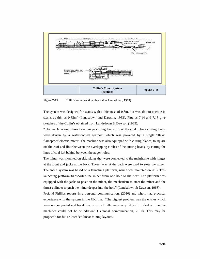
7-30
Collin’s Miner System (Section)
Figure 7-15
Figure 7-15 Collin’s miner section view (after Landsdown, 1963)
The system was designed for seams with a thickness of 0.8m, but was able to operate in
seams as thin as 0.65m” (Landsdown and Dawson, 1963). Figures 7.14 and 7.15 give
sketches of the Collin’s obtained from Landsdown & Dawson (1963).
“The machine used three basic auger cutting heads to cut the coal. These cutting heads
were driven by a water-cooled gearbox, which was powered by a single 90kW,
flameproof electric motor. The machine was also equipped with cutting blades, to square
off the roof and floor between the overlapping circles of the cutting heads, by cutting the
lines of coal left behind between the auger holes.
The miner was mounted on skid plates that were connected to the mainframe with hinges
at the front and jacks at the back. These jacks at the back were used to steer the miner.
The entire system was based on a launching platform, which was mounted on rails. This
launching platform transported the miner from one hole to the next. The platform was
equipped with the jacks to position the miner, the mechanism to steer the miner and the
thrust cylinder to push the miner deeper into the hole” (Landsdown & Dawson, 1963).
Prof. H Phillips reports in a personal communication, (2010) and whom had practical
experience with the system in the UK, that, “The biggest problem was the entries which
were not supported and breakdowns or roof falls were very difficult to deal with as the
machines could not be withdrawn” (Personal communication, 2010). This may be
prophetic for future intended linear mining layouts.

7-31
7.6.6 Full-face miners
Landsdown (1963), comments on full face miners, “These mining machines span the
whole width of the panel that was mined and the entire machine is advanced or retreated
along the entire machine width at once. The advantage of these machines were that they
were able to mine seams as thin as 40cm (0.4m), but because of the size of these
machines, these machines utilise a huge amount of equipment and people had to work in
the working face for the purpose of maintaining the machines.
One example of a Full-face miner is the In-seam miner. All types of Full-face miners
worked on the same principle, coal is removed from the face with sideways moving,
cutting devices” (Landsdown and Dawson, 1963).
In-seam Miner Figure 7-16
Figure 7-16 In-seam miner (after Landsdown, 1963)
7.6.7 Scraper box installations
This system is one of the older and simpler forms of longwall-type operations.
Landsdown recalled, “Originally scraper boxes were only used as haulage units in hand-
worked longwall panels, in thinner seams. A scraper box is made up of a box, open at the
bottom, front and top, with a scraper blade hinged into the back of the box. When the
scraper box is drawn forward the scraper blade is pulled open, allowing the scraper box to
gather coal and move the coal to the conveyor, when the scraper box is drawn backward,

7-32
the scraper is forced shut and the scraper box is able to move unhindered in the panel. To
increase productivity, in many cases, more than one scraper box is used in tandem with
the other scraper(s) in the longwall panel (the system is not unlike the Witwatersrand
scrapers used to clean stopes).
The premier scraper box method was known as the Haarman. With this method a heavy
skid board is used to press the scraper box against the face, to cut thin coal slices from the
face with each pass of the scraper box.
Another scraper box method, namely the chain tension scraper method is also used. With
this system, the skid board is removed and is replaced with a heavy duty chain, which
runs along the length of the panel, where the ends of the longwall face are kept slightly
ahead of the middle of the face, to facilitate chain movement along the face”
(Landsdown & Dawson, 1963).
Chain Tension Scraper Layout Figure 7-17
Figure 7-17 Chain tension scraper layout (after Landsdown, 1963)
“The system still requires people to work on the working face, to install support. Because
of this, the system could only be applied on seams with a thickness of 40cm and more.
Large winches are required to move the scraper boxes across the face. Skid boards
prevent easy access the face” Landsdown (1963).

7-33
7.6.8 Highwall mining
Highwall mining is a process of extracting coal reserve that is exposed in the highwall
created during surface mining. The immediate advantage of highwall mining is that coal
reserves can be extracted that would otherwise be uneconomic to mine by conventional
surface mining techniques due to high stripping ratio. It can also be utilised to extract coal
left as support or as waste during underground mining operations. Since mining of high
wall entries is achieved by leaving overburden undisturbed, the economics of the system
are independent of strip ratio.
Treuhaft (1981), “The system uses augers or continuous miners to extract the seam in the
highwall. Standard augers, available on the market operate as blind boring and extraction
systems. They remove coal from a relatively horizontal seam which is exposed by
removing overburden to form a bench or highwall. Auger mining techniques are primarily
used to recover coal from the surface where stripping operation or underground methods
are not suitable. Though productivity is good under ideal conditions, only 30% to 40% of
coal is recovered by this method. Large amounts of coal are left above and below the
auger hole and in webs between each hole.
Layout of HW Mining Operations Figure 7-18
Figure 7-18 Layout of highwall mining operations (after Treuhaft, 1981)

7-34
Primarily there are two highwall systems being used extensively worldwide, namely the
older Auger mining system and the newer Addcar mining system” (Treuhaft, 1981).
The Dual Auger Mining System
Treuhaft reported that, “the highwall auger mining system, at extended depth provides an
excellent approach for extracting coal from thin seams. This method is amenable to
relatively level working ground or foot wall and coal seams. In practice, a series of
parallel trenches would be progressively excavated across the mining property. The coal
between the trenches will be augered as the excavation proceeds. This method of
extracting coal is especially economical as less than 10% of the mining area would
require overburden removal and reclamation. This situation is both environmentally and
economically suitable and hence has potential in its applicability. Coal handling
requirements for the Highwall Mining System is not critical, as the trenches are wide
enough to allow free movement of vehicles and if necessary, for coal to be easily
stockpiled in the pit. Alternatively, coal could be easily elevated from the pit via elevating
conveyors so as to reduce pit congestion.
The Highwall Mining System is based on the dual auger configuration to maximize
recovery and control without compromising flight handling and storage capabilities. The
Highwall Mining System differs from the conventional machines due to the presence of
895kW multi-speed auger drive trains and vertical storage facility of augers. Such a high
power multi-speed engine is required to achieve the desired production rate when boring
at extended depths. To accommodate the system into narrow benches and increase the
mobility, the whole unit is composed of three trailer units, two auger bays and one main
carriage. The augers are made of alloy tubes, thus making it considerably lighter than the
conventional auger flights. This reduces the dead weight to be carried and saves on power
due to reduction in frictional losses. More power can thus be utilised for productive work
like cutting and conveying of coal.
A conveyor belt system is used for transporting coal which is discharged from the auger
borehole. Coal is first loaded into a small belly conveyor which discharges its load into a
small face conveyor which moves the coal to the outer edge of the Highwall Mining
System structure. After leaving the face conveyor, coal is discharged onto a loading
conveyor which elevates it into haul trucks or stock piles. The elevating conveyor is
pinned to the Highwall Mining System, but can be easily removed and driven to the
opposite side to maintain compatibility with the direction of advance.

7-35
The production capabilities of the advanced Highwall Mining System is dependent on
time required for boring, flight handling, flight retrieval to and from the bays, and
tramming of the machine from one hole to the next” (Treuhaft, 1981).
The Addcar Mining System
“This current system is only able to extract seams with a thickness of 0.9m or more, thus
it is still able to extract thin seams. Although the system is unable to extract seams as thin
as the Dual Auger system, it is able to extract coal at a much larger tempo than the Dual
Auger system and is able to penetrate the highwall far deeper and more accurately than
the previously mentioned system. The system is able to recover up to 60% of reserves
using 12.5m individually powered addcars. The standard system depth extends to 365m,
but newer upgraded models have an extended range of up to 500m.
The system uses a continuous miner and addcars, which use chain conveyors to remove
coal from the entry, to extract the seam from the highwall. As the continuous miner
extends deeper into the highwall, additional addcars are added to the string, to enable the
continuous miner to reach the desired depth. When this depth is reached and the coal on
the conveyor is removed to the dump trucks or stockpile, the individually powered
addcars added on to the string, are then, one by one, decoupled from the string, until the
continuous miner is extracted from the hole. The process can then restart on a new hole
and the whole process is then repeated” (Treuhaft, 1981).
Addcar Mining System Figure 7-19
Figure 7-19 The Addcar Highwall system (after Treuhaft, 1981)
7-36
It is apparent to this researcher that the Highwall Mining System is promising in its
applicability. This system can be successfully applied in extracting very thin seams which
are otherwise uneconomic to mine by open pit or underground techniques. Since mining
by highwall entries require considerably less overburden removal, the system has high
economic potential. This system also demands very low manpower compared to
conventional mining techniques.
7.6.9 The Longwall Mining System
Thin seam application of wall mining is discussed in this section. “Longwalling is used to
mine coal seams with a significant lateral extent, where roof control is difficult and seam
thickness is sufficient. There are two different types of longwalling, namely advance
longwalling and retreat longwalling. Retreat mining is used much more often the advance
longwalling. With advance longwalling, the development entries are developed slightly in
front of the advancing face, away from the main entries to the panel. In contrast, With
Retreat Longwalling, the entire section is developed, prior to the commencement of
production from the longwall face, at the very end of the development, the face is then
mined back in the direction of the main entries, and the face is thus retreating”. Advance
has a single entry at each end of the face running parallel to each other for the length of
the panel often developed simultaneously with the advance extraction of the face. Retreat
longwalls usually have multiple entries (two or three) and are completed before the retreat
mining of the panel commences.
Landsdown (1963) reported, “Development in a longwall section that is carried out for
the longwall pillars is done using a continuous miner and the room and pillar method. The
entries accessing the longwall panel are called the maingate and tailgate entries, typically
the ventilation intake is at the maingate and the ventilation return is at the tailgate. When
one panel is mined out, the maingate of the mined out panel becomes the tailgate of the
next panel, thus just extending the intake of the ventilation.
A longwall system was developed for thin seams, this system uses a coal plough in
basically the same way conventional longwalling uses a shearer. The coal plough is able
to mine coal as thin as 0.45m, but hydraulic support units are unable to support a panel
lower than 0.75m in height, greatly reducing the productivity of the system. This whole
system uses all the same equipment as a conventional system. The plough moves back
and forth along the face, peeling coal from the face onto the armoured face conveyor. The
armoured face conveyor has two main functions, namely to guide the coal plough unit on

7-37
the face during mining and to transport the broken coal out of the working face. There are
various problems with the coal plough such as that it is prone to cut into softer floors, it
has difficulties in seams where the coal hardness is not constant across the face and the
feasibility of the systems is questionable in seams lower than 0.60m.
Longwalling offers enhanced safety due to the system of face support units that cover the
entire working face. The system also allows for higher extraction ratios, conserving
valuable coal reserves. The system allows greater flexibility when dealing with problems
such as mining at depth, multiple seams and a significant reduction in roof bolting.
High capital cost is associated with the equipment required for the system. Due to high
cost of the equipment, stoppages in production cause major financial losses.
There are a lot of problems associated with gas, seam thickness and with soft floor and
roof conditions. In areas where the roof conditions above the seam are thick and strong, it
is difficult to ensure controlled caving. It is very difficult to practice this system in areas
with many geological features” (Landsdown & Dawson, 1963).
LW Coalplough System Figure 7-20
Figure 7-20 The Longwall coal plough system (after Landsdown, 1963)
7-38
7.6.10 Modern systems as at 2008
New proposed mining systems to be used are aimed at the increased productivity and
profitability of thin seam coal mining in South Africa. The two systems are
conceptualised by taking into account past experiences.
The first mining system to be discussed is called Underground Auger Mining. The second
system is the Continuous Miner System, which offers two alternatives of a Drum Shearer
Continuous Miner System and an Auger Continuous Miner System. In all of the systems
to be discussed backfilling will be the primary form of support.
Underground Auger Mining
This system is based on surface auger mining operations, which have been proven to be
very successful in mining thin coal seams in the past and is still used to this day with ever
increasing success. The surface auger mining equipment has been adapted for
underground use and has been tested to some extent in coal mines in the U.S.A. where
success was achieved at the mines where the equipment was tested.
Underground auger mining was successfully implemented by Balkan Auger in Derby
seam in the state of Kentucky in the U.S. The Derby seam is 72.5cm (0.725m) in height
and is sandwiched between sandstone. The average production of this machine was
450t/shift and the best was 585t/shift (Holman et al, 1999).
The layout of the system is loosely based on conventional underground development of
an underground coal mine. The main entries and headings in the panels are developed in a
similar pattern to a typical longwall coal mine. Breakthroughs or crosscuts (splits)
connect the two parallel main headings. The panel entries and the headings have a
rectangular cross section of 6m in width and 2.5m in height to accommodate the mining
machines in the section. The development of the section can be done with continuous
mining machines or with conventional drilling and blasting.
From the main heading 1,200m long panel entries will be driven perpendicularly every
400m. Panel entries will be connected to ventilation return airways.
Double headed augers will be used to do the in-panel mining and they will advance
approximately 180m at an angle of 90º into the coal seam from the panel entries, the
augers are able to steer horizontally and vertically. Two augers will mine into the panel
simultaneously, 12m apart on the same side of the entry. Each auger will mine a strip
1.2m wide and 180m long, every 4.5m apart. Steering of the cutterhead inside the auger
hole is of great importance if the system is to achieve its production targets and success.
All of the holes created by the mining will be backfilled and sealed immediately after the
auger is removed from the auger hole.

7-39
UG Auger Mining Layout Figure 7-21
Figure 7-21 Face layout for the Underground Auger mining layout (from Holman, 1999)
After one side of the entry has been completed, the augers will move to the other side of
the entry and mine the panel out in the same manner. When the mining on the second side
has been completed and the backfilling in the first side of the entry has been allowed to
cure, the augers can return to mine the webs between the previously mined holes, leaving
a 0.6m rib pillar on each side. This process is repeated until the whole panel is mined out.
The coal mined out during the operation is transported to the conveyor belts in the main
heading. The backfilling of the completed holes will maintain the integrity of the ground
conditions. During augering nitrogen can be injected into the holes to reduce the risk of
methane explosions. Ventilation in the panel entries will flow from the ventilation intake
in the main heading to the return airway on the other side of the panel.
The system uses a pressure system to steer the cutterhead. Hydraulic jacks located right
behind the cutterhead barrels are extend outwards against the walls of the auger hole to
initiate the steering of the auger. When the jack pads are forced against the walls of the
auger hole, force is exerted on the cutterhead, which force the cutterhead to change
direction (Holman et al, 1999).
The Continuous Miner
The continuous miner was designed and created to address the problems associated with
older thin seam miners. The older thin seam miners had problems such as the lack of

7-40
control the operator had over the steering of the thin seam miner, the inadequate coal
transportation systems, inability to meet production potential and the lack of an accurate
coal and rock interface sensing equipment.
There are two types of continuous miners available on the market at present (2008)
namely the drum shearer continuous miner and the auger-head continuous miner (Holman
et al, 1999).
Drum Shearer Continuous Miner. Initially this type of continuous miner was designed
and built to mine middle to thick coal seams. Only in recent years have they been adapted
to operate in thin coal seams. The unit is displayed in Figure 7.22.
Joy Technologies declare that, “These continuous miners are able to mine coal seams as
thin as 80cm. Drum Shearer Continuous miners are well known for their high production
rates and reliability. The continuous miner system is a fully integrated system, comprising
of the self propelled Continuous miner and the flexible, self propelled conveyor train
system” (Http://www.joy.com.html, 2006).
Joy 14CM with 750mm Cutting Drum Figure 7-22
Figure 7-22 JOY 14 CM cutting system with a 750mm cutting drum (after joy.com, 2006)
The continuous miner uses the same panel entries as used in any coal mine, but it cuts the
coal at an angle of between 30º and 40º from the main panel entries. This layout enables
the continuous miner and the conveyor train to be able to handle turns without needing a
large clearance. The panel layout is based on a longwall panel layout
(Http://www.joy.com.html, 2006).
The size of the shearer drum on the continuous miner is governed by the thickness of the
seam to be mined. The continuous miner rides on two caterpillar tracks, which are

7-41
powered by a flameproof electric motor and the shearer drum is powered by its own
flameproof electric motor. The caterpillar tracks on which the continuous miner rides
provide the necessary forward thrust for the shearer drum to cut the coal.
CM & Backfilling Linear Layout Figure 7-23
Figure 7-23 Continuous miner and backfilling operation (after joy.com, 2006)
Thin Seam CM &CH Figure 7-24
Figure 7-24 The Continuous Miner and the conveyor train (after joy.com, 2006)
The continuous miner has two gathering wheels at its front, which act as arms to gather
the broken coal onto its chain conveyor, which in turn discharges its load onto the
conveyor train. A schematic of the backfilling is presented in Figure 7.23.

7-42
The backfilling allows the creation of small ribs and results in higher extraction
percentage. The Continuous haulage is displayed in Figure 7.24. The chain conveyors out
of which the conveyor train is made up are composed of 3.7m long units, attached back to
back, to form a conveyor train. Each of these conveyor units are powered by their own
small flameproof electric motor. The stall in which the Continuous miner is cutting must
be ventilated to prevent methane explosions that could occur due to sparks generated by
the cutting process or faulty electrical equipment. Fan ducts are fixed to the conveyor
train and are pulled into the stall as the stall progresses. A normal uniaxial flow fan can
be used to generate the necessary air pressure and air quantity. An acceptable layout is
depicted in Figure 7.25.
The continuous miner is equipped with and guided by built in coal and rock interface
sensory equipment which will continuously monitor the cutting direction.
Linear Mining & Ventilation Layout Thin Seam CM Panel
Figure 7-25
Figure 7-25 Mining and ventilation layout for a Continuous Miner section (after joy.com,
2006)
The vertical positioning of the cutter drum will be controlled by two hydraulic rams
which will raise or lower the cutter drum above or below the horizon
(http://www.fairchildtechnologies.com, 2006).

7-43
The Auger Head Continuous Miner. This mining method is used to extract coal seams
to a minimum of 0.6m and has been used to great success worldwide. The system
originated in the U.S.A and was soon brought to South Africa. In the Appalachian region
in the U.S. auger head continuous miners are extensively used. This system was
successfully introduced in South Africa in the Gus seam at Hlobane colliery some 27
years ago and achieved considerable tonnage from the Gus seam’s high grade coal. Seam
heights varied from 0.6m to 1.3m. Figure 7.26 displays the Fairchild dual auger CM with
Figure 7.27 displaying a potential layout (http://www.fairchildtechnologies.com, 2006).
The dual auger continuous miner uses the same layout as used for the drum shearer
continuous miner. The only difference is that the dual auger continuous miner is able to
take out broader slices of coal but does not advance at the same pace as the shearer drum
continuous miner (http://www.fairchildtechnologies.com, 2006).
Fairchild Dual Auger CM Figure 7-26
Figure 7-26 Fairchild Dual Auger continuous miner (from fairchildtechnologies.com, 2006)

7-44
Dual Head Auger Operation & Stull Ventilation
Figure 7-27
Figure 7-27 Dual Head Auger operation and stull ventilation (from airchildtechnologies.com,
2006)
7.7 Conclusion
1) If the South African coal mining industry is to remain one of the world’s largest coal
exporters, it needs to maintain a steady production of coal, which it will only be able
to do if it starts to exploit the untouched thin coal seams and existing resources
wisely.
2) It can be seen that that the methods of thick seam mining and thin seam mining are
numerous and it becomes a daunting task for the mining engineer to effectively
decide on which system to use.
3) In South Africa, very effective research work has been done by a number of mining
engineers and this has led to the understanding of critical factors in selecting specific
mining systems.
4) It is the objective of this researcher to concentrate on mechanised mining that proves
to be regarded as best practice, be it thick or thin seam mining, and either bord and
pillar or wall systems using either or both primary and secondary strategies.
5) It should be noted that the most productive wall face in the world at Xstrata’s Bulga
Beltana Highwall Mine, NSW, Australia produces in excess of 5.5Mtpa from a single
longwall operation at a 3m height profile, consistently beating Anglocoal’s,
Moranbah North in Queensland which has been identified as the next best, and
operates at slightly over 4m height.

7-45
6) It is very possible that in future non - entry mining methods may become more
pronounced. These are methods in which man is remote of the working face and
applies automated or telemetric techniques. Another aspect of non – entry process
may include in-seam gasification to get to the chemical and calorific potential of the
fossil fuel. However, these processes are currently deemed to be inefficient. Coal-bed
Methane is a reality however and operators are considering this at increased resource
depth.
7) There is a critical height of approximately 2.5m beyond which no difference in
productivities in the thicker seam ranges are discernable. A 3m face should compete
with a 4 or 5m face in delivery. The critical factor lies in the access of people in many
instances: Is it possible to walk upright? (Phillips, Personal communication, 2010).

8-1
8 WALL MINING METHODS
8.1 Introduction
The parameters of choice, including the factors of choice were evaluated in Chapter 6,
factors were identified which could assist the engineer in choosing a mining method. In
Chapter 7 systems applicable to thick seam and thin seam profiles were reviewed.
In this Chapter the emphasis is on method. Method focuses on strata control (caving or
support etc.) layout and equipment permutations. The research looks at specific
applications that are likely to deliver best practice results.
In this chapter, wall mining is treated as the generic term for longwall, shortwall and
midwall mining. A shortwall in South African terminology in reality is a short longwall.
Authors still prefer the name longwalling or longwall for either derivative but the term
shortwall in its modern context is widely used. It should be understood that
internationally a shortwall originated as a method exploiting a retreat panel as in longwall
mining but combining the shield or chock mechanised support units with a CM and
shuttle cars.
Partial extraction implies pillar mining (bord and pillar) where pillars are left as support.
Pillar extraction implies the secondary extraction of the developed pillar. This may take
the form of full extraction (removal of the pillars within the panel, completely) or partial
pillar extraction (leaving of pillars, fenders and snooks in the increased extraction panel).
Partial extraction is not partial pillar extraction but rather bord and pillar mining.
The research will now consider those methods implemented at collieries that may form
part of the benchmarking exercise and identify best practice methods, from which can be
learnt and consequently permit the development of guidelines which will allow operators
to implement best practice systems thus ensuring industry effectiveness and efficiency.
The focus is on specific methods that do well in their regions due to some comparative
advantage either physical or managerial. It must be noted that the soft systems
(managerial) have an enormous potential of encouraging continuous improvement.
The process of mining engineering often involves the declaration of reserves. Resources
are accordingly declared by the geologist while the mining engineer must determine the
reserve after applying his/her choice criteria.
From the SAMREC code it is seen that, “Resources are normally defined by:

8-2
GTIS (Gross Tonnes in Situ) which qualifies all coals above a minimum seam thickness
and cut-off grade.
TTIS (Total Tonnes in Situ) has geological and modelling losses applied.
MTISTh.MH (Mineable Tonnes in Situ, theoretical mining height) is the coal in the area
defined by seam thickness and depth or strip ratio cut-off, including geological and
modelling losses applied.
From this the Mining Engineer will determine Reserves as MTISPr.MH (Mineable Tonnes
in Situ, practical or preferred mining height, is coal in an area defined by minimum and
maximum mining heights less layout losses times average mining height thickness times
average RD including geological losses and modelling losses. including dilution.
RoM (Run of Mine) Reserve is the (MTISPr.MH times mining Extraction factor/ 1-
percentage contamination, times mining recovery factor, times 1+ percentage moisture
correction factor).
Saleable Coal Reserves, Sales, is the sum total of all products after coal processing
operations. It is the (RoM times percentage yield times (1+ percentage). Sales moisture
correction factor (moisture added by preparation plant needs to be eliminated we have
moisture as received and air dried. Air dried discounts extraneous moisture. This is often
taken as 3% and influences the true volume and hence tonnage of coal mined)”
(SAMREC Code, 2007).
8.2 Wall Mining
The report will now take a look at longwall, midwall and shortwall mining. The definitions
are a function of face length or the distance between the maingate and tailgate.
The thin seam section in the Chapter 7 introduced the method but here it is explained from a
world class perspective in thick seam applications. Figure 8.1 displays a Wall face with and
exaggerated view superimposed.
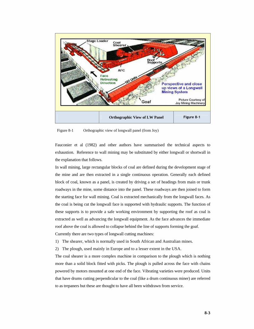
8-3
Orthographic View of LW Panel Figure 8-1
Figure 8-1 Orthographic view of longwall panel (from Joy)
Fauconier et al (1982) and other authors have summarised the technical aspects to
exhaustion. Reference to wall mining may be substituted by either longwall or shortwall in
the explanation that follows.
In wall mining, large rectangular blocks of coal are defined during the development stage of
the mine and are then extracted in a single continuous operation. Generally each defined
block of coal, known as a panel, is created by driving a set of headings from main or trunk
roadways in the mine, some distance into the panel. These roadways are then joined to form
the starting face for wall mining. Coal is extracted mechanically from the longwall faces. As
the coal is being cut the longwall face is supported with hydraulic supports. The function of
these supports is to provide a safe working environment by supporting the roof as coal is
extracted as well as advancing the longwall equipment. As the face advances the immediate
roof above the coal is allowed to collapse behind the line of supports forming the goaf.
Currently there are two types of longwall cutting machines:
1) The shearer, which is normally used in South African and Australian mines.
2) The plough, used mainly in Europe and to a lesser extent in the USA.
The coal shearer is a more complex machine in comparison to the plough which is nothing
more than a solid block fitted with picks. The plough is pulled across the face with chains
powered by motors mounted at one end of the face. Vibrating varieties were produced. Units
that have drums cutting perpendicular to the coal (like a drum continuous miner) are referred
to as trepaners but these are thought to have all been withdrawn from service.

8-4
8.2.1 History
The coal plough was used in Germany during the war. Mechanised versions of wall mining
commenced in the UK soon after WWII in the late 1940’s and early 1950’s.
International best practice has however been identified in Australia which has an efficient
coal industry in the states of Queensland and New South Wales (NSW).
The mechanised method of longwall mining was first introduced to Australia in 1963 and in
2005 there were 27 longwall faces operating in Australia (NSW Dept. of Primary Industries,
2008). Production from Australia's longwall faces represented 18% of Australia's raw black
coal production of 398Mt in 2005. This percentage accounts to 89% of Australia's total
underground black coal production of 80Mt.
A detailed account of the development of mechanisation is depicted by the work of former
General Manager of Maderly Wood Company, Mr D Eagar a deceased member of the
Institute of Mining Engineers in his work on wall cutting machinery (Eagar, 1920). “Eager
wrote, “There are two methods of longwall mining that are used throughout the world:
1) Longwall retreat mining,
2) Longwall advance mining
There are two methods used to cut a web of coal from the longwall face:
1) The "Bi-Directional" (bi-di) method. The shearer cuts a fresh web of coal each time
it traverses up and down the coal face.
2) The "Uni-Directional" (uni-di) method. The shearer cuts a web of coal from one side
of the face to the other and then returns back down the face to clean up the original
web without further advancement of the powered supports. The individual contributions to productivity are undefined at this stage. Different
operators have different preferences” (Beukes, Personal communication, 2009).
8.2.2 Advance wall mining
Fauconier stated, “In longwall advancing, the longwall face is set up a short distance from
the main development headings. The gate entries of the longwall face are formed as the coal
is mined. The gate roadways are thus formed adjacent to the goaf. Normally the gate roads
are protected from the goaf by a line of packs, which are built to provide protection to the
gate roads and minimise excessive circulation of air between the gate entries through the
goaf. The gate entries are known as main gate and tail gate. The gate roads servicing an
advancing longwall panel are single entries and each coal panel is separate from the adjacent
workings with a solid barrier pillar, whose width is dependent upon the depth of the working.
Generally the main gate contains the belt conveyor and the pantechnicon or power train for
facilitating power and logistics to the longwall face” (Fauconier & Kersten, 1982).

8-5
Advance LW Figure 8-2
Figure 8-2 Advance longwall mining (After Fauconier 1982)
In Figure 8.2 the pillar between the panels is made up of two gate roads one for each
panel and an interpanel pillar as depicted in the exploded view of the pillar as identified
by the arrow.
8.2.3 Retreat wall mining
In retreat longwall mining, two sets of entries are driven between 100 to 250m apart,
however Australia (Beltana) is planning faces of 400 – 500m in length (panel width). When
the entries have been driven a predetermined length, say 2km, they are connected and a
rectangular longwall block is outlined. The longwall face is then installed and as mining
continues into the panel, back to the original development, the entries are allowed to collapse
behind the face line to form part of the goaf. The gate entries are known as main gate and tail
gate. Generally the main gate contains the belt conveyor and the pantechnicon for facilitating
power and logistics to the longwall face.

8-6
Retreat LW Figure 8-3
Figure 8-3 Retreat longwall mining (After Fauconier 1982)
The advantages of retreat mining are now well established, but nevertheless worth restating:
1) Developing round the area to be extracted reduces the risk of encountering
unknown geological hazards, and this can be reinforced further by long-hole
horizontal drilling.
2) The road making processes are separated from the production processes, leading
to a simpler face organisation.
3) Elimination of stables (a stable is the advance portion of the gate road which
accommodates the coal winning mechanism for development of the gate road)
leads to simplification of gate-end techniques.
4) Road-way maintenance can be reduced.
5) Risk of spontaneous combustion is greatly reduced, and control and sealing off
are simplified.
6) Dykes and other geological obstacles can be mined out during the development
stage, thus reducing delays during production.
7) Salvage of the face is more rapid and complete, as the face finishes close to the
main transport system with minimum lengths of disturbed roadways to be
negotiated.
8) The above advantages can lead to greater consistency of output and faster rates of
advance.

8-7
The listing of the obvious advantages of retreat mining leads to the inevitable question as to
why it is not more widely practiced in Europe, where the system originated (Clarkson et al,
1981):
1) “Since the 1960’s and 1970’s has the system spread to depths of over 500m. The fear
that roadways would not stand at depth was the greatest inhibitor, but there was
evidence that depth is not the critical factor, and correct disposition and size of
roadways are more important.
2) The introduction of equipment capable of sustained high-speed advance in the
development stage has been the main reason why retreat mining has become more
accepted. This imposed a discipline on management, and in retreat mining
development became the priority.
A new emphasis is placed on design, as follows:
1) A good supply system, as rates of advance in development work will be much higher
than in normal production sections.
2) With consistent face performance available, there is emphasis on bunkers, which may
be required for higher outputs of development coal and stone. The coal clearance
system of the whole mine must be re-examined, and in-bye bunkers considered to
even out the high surges characteristic of longwalls.
3) The discipline of establishing an integrated face design many months before the face
is set up, and adhering to it without deviation has to be accepted.
4) Equipment training and organisation are necessary to obtain the high development
rates required” (Clarkson et al, 1981).
8.2.4 Types of layout
A variety of layouts are available, but they fall broadly into three categories:
1) New roads are driven in the solid for each face.
2) One or more roads already exist from previous faces.
3) One roadway is the repaired or remaining road of a previously retreated panel and the
other is a new roadway driven in to the solid.
In South Africa development is normally carried out by board and pillar mining, and often
with two road sections leaving long chain pillars. 'This configuration leads to low machine
productivity during development (Buchan et al, 1981).
8.2.5 Factors impacting on the design of wall layouts
These factors have been well defined by Buchan et al (1981) and Fauconier & Kersten
(1982), and have been repeated here for completeness. There is no standard design of
mine layout capable of meeting the widely differing conditions met with in coal mining.

8-8
However, examination of the relevant factors has led to the identification of common
ground, which can lead to some degree of design guidance.
The factors involved can be: fixed; variable.
Fixed factors
Fixed factors, which influence the design of a longwall mining system, include the
following: depth; full thickness of seam; proximate geology; general geology; water; gas;
surface restrictions; old workings; spontaneous combustion.
Depth. This influences the major dimensions of the panel; in South Africa where
massive competent dolerite exists, rock mechanics considerations play a critical role in
determining panel dimensions.
Full thickness of the seam. This includes dirt bands and coal left for support or quality
reasons, and it influences the choice of development equipment, method of working, and
the panel width.
Proximate geology. The geology likely to affect the face can be considered in terms of:
1) “Relative strength of rock and coal strata above and below the seam and their lateral
variability. This influences the thickness of extraction, the width of the panel, choice
of face machinery, and type of face and roadway supports,
2) Natural and induced fracture patterns, zones of highly stressed strata from past
workings, and minor faulting. These influence the position of developments, and
hence the width of panel and direction of working, which can seriously affect the
results from the face,
Gradient (full dip) of the seam influences the general face layout and general pattern of
extraction for all faces in the area to be worked” (Fauconier & Kersten, 1982).
General geology. Geology in its primary and secondary structure including:
1) “The extent to which the measures as a whole have been disturbed (compressed
and/or hardened) by folding, faulting, burial, and subsequent elevation to the surface,
or invasion or baking by nearby igneous rocks.
2) The overall proportion of innately harder to softer rocks in the measures.
3) Any non-coal measures of different stiffness or density, which might overlay the
sequence, either conformably or non-conformably” (Fauconier & Kersten, 1982).
Water. Whether emerging onto the face or roadways, or whether by its presence in strata
above the working area, water influences face design. In the former instance, it may
restrict the planned rate of advance or it may affect geological and environmental
conditions. In the latter case, it can influence the method of face support, rate of advance,
and width of panel.

8-9
Gas. Where present in large quantities, gas influences the width of the panel and rate of
advance and can inhibit seriously the wide scale application of retreat mining. However,
methane is generally more easily drained from longwalls than board and pillar workings
because the main ventilation flow is concentrated along the single working face.
Surface restrictions. In the form of property or services requiring support, these
restrictions influence the pattern of extraction where support pillars are required.
Old workings. Old workings that exist at the time of planning, whether above, below, or
in the seam, influence the main lines of development; disposition, width, and length of
panels. Pillars left between panel seams above and below the seam to be worked induce
fracture patterns and create zones of highly stressed strata, which can affect performance
seriously.
Spontaneous combustion. Spontaneous combustion is possible under certain conditions,
especially in thick seams. It may involve leaving pillars in order to isolate working areas
(closed panel system). Often the heating needs to be controlled by applying suffocation
techniques which are only possible if the panel can be sealed.
Variable factors
Variable factors that the mine designer can alter include:
Other planned workings. Such workings in the same seam or in other seams are a
variable factor in respect of disposition and scheduling of panels.
Width and length of panels. These factors, coupled with thickness of extraction and the
planned rate of advance, determine the face output. In some circumstances may be
predetermined by some or all of the fixed factors previously referred to, but in most
circumstances a wide range of choice is available.
These are critical factors and require serious investigation to provide the most economic
return from the face. Fauconier recorded, “The economic length of longwall can be
calculated from the following basic information:
1) Depreciation and maintenance costs of face supports and conveyor, which are
proportional to the length of the face.
2) Depreciation and maintenance costs of the shearer, conveyor, and roadway
development costs. These costs are inversely proportional to the face length,
3) Cost of installation and removal of face equipment, which are independent of
face length.
The optimum length that can be calculated from these considerable values is often
overridden by:
1) Geological problems such as presence of a massive dolerite.

8-10
2) Availability of reserves.
3) Other workings” (Fauconier & Kersten, 1982).
Thickness of extraction. Except in the case of thick seams, the choice is limited to
thickness of the coal seam, less that thickness required to support the roof or floor of the
seam.
Induced fracture pattern and zones of high stress. These result from present as well as
past workings, bi disposition of the panels in relation to adjacent, subjacent, or
superjacent workings can allay their effects considerably reduce the effect that panels will
have on future workings.
Width and number of pillars between panels. These play an important part in strata
stability affecting the face and particularly the roadways. Where multi-entry
developments are used, the distance between entries and the panel width can be critical.
The pillar left between adjoining panels must be large enough to contain both flank
abutments. The design of development sections for longwall retreat is a balance between
productivity during development and overall extraction of reserves.
Method of working. The method of working is the key factor in the design field. The
consequences of the choice, for example a heavy development program required to block
out an area for retreat mining, must form an integral part of the mining plan.
Un-worked seams above or below. Such seams can influence decisively the design,
particularly if their future working is considered. Problems of gas emission, the choice of
working two thinly separated seams as one, or only working one of them, the choice of
working better quality seams out of sequence, the consequent effect upon conditions in
upper and lower seams that are to be worked later, must be considered.
System of support. The support system for the full length of the face has become a less
critical factor with the almost universal use of powered supports. There are many
instances of improperly designed or inadequate supports in use, however, which give rise
to strata control problems and lower productivity than expected.
Rate of face advance. This is the single factor, which, once the face design is completed,
determines the output from the face. The effect of face advance strata conditions, gas
emission, and other factors also has to be evaluated.
Number and sequence of seams to be worked. These factors are related closely to
subsidence. The inter-relation of mine layouts in successive seams must be examined.
The great number of seams, the more complex the inter-relations become.
Direction of extraction. This is important in relation to the method of working and to
water and gas emission problems. Retreating to the rise, preferred in wet conditions,
8-11
poses a development problem, as entries must be driven to the dip. The opposite set of
conditions can arise if gas emission is thought to be a problem.
Method of development for wall mining.
The equipment used in developing must be adequate for the purpose. In retreat mining it
is vital that face and development heading design be much more closely integrated than is
normally the case in advancing mining. Face and heading design requires:
1) “Major exploratory development, to explore and develop reserves from the shaft
complex. Board and pillar mining by continuous miners and shuttle cars,
2) Subsidiary development, to block out reserves for production sections. Board and
pillar mining by continuous miners and shuttle cars,
3) Longwall development to prove and develop individual longwall panels. Board and
pillar mining by continuous miners and shuttle cars,
4) Longwall retreat of pre-developed panels” (Buchan et al, 1981),
Modified pillar extraction methods may be necessary to consider in areas not suitable for
longwalling and the required development designed (Buchan et al, 1981).
Extraction of reserves
The typical extraction rates comparatively are illustrated in the Table 8.1. Steps need to
be taken to ensure maximum reserve utilisation.
Mining methods employed for development
Continuous miners and shuttle cars are the normal choice but continuous haulages may be
effectively applied.
The extraction of part or all of the development pillars between the longwalls is under
active consideration in several operations in South Africa, and if successful would have
the following advantages:
1) Increased overall extraction of the reserves.
2) A smoother surface subsidence effect. Improved strata control by a smoother transfer
of load from one face to the next.
3) This may avoid the gradual build-up of load on successive longwalls that is common
when development pillars remain stable (Clarkson et al, 1981).

8-12
Table 8-1 Extraction rates (After Fauconier, 1982)
Conventional B&P Depth to floor Percentage extraction
achieved
6m bords 2.0 SF; 7% haulage
& barrier loss (layout); 10%
geological loss
50 63.4
“ 100 56.8
“ 150 42.8
“ 200 35.9
“ 50 74.2
60m Shortwall
Retreating between 3 road
development; 7% haulage &
barrier loss (layout); 10%
geological loss
100 68.2
“ 150 67.2
“ 200 56.4
“ 50 74.1
100m Shortwall
Retreating between 3 road
development; 7% haulage &
barrier loss (layout); 12%
geological loss
100 70.3
“ 150 66.4
“ 200 62.6
“ 50 73.1
200m Longwall
Retreating between 3 road
development; 7% haulage &
barrier loss (layout); 15%
geological loss
100 71.2
“ 150 68.6
“ 200 66.2
“ 50 70.0

8-13
Strata behaviour
In order to combine practical experience and rock strength measurements into a workable
explanation of strata behaviour during mining operation, understanding of the mechanics
of strata movement is necessary. This section tries to relate some relevant facts of rock
mechanics and practical experiences of strata control. Rock mechanics considers rock as a
coherent mass, roughly obeying the laws of elasticity until the yield or failure strength is
exceeded. Sometimes violent failure can occur, but most coal measure strata fail non-
violently, except dolerite in certain circumstances.
The characteristics of rock that mainly concern mining engineers are:
1) Strength,
2) Competence,
3) Thickness of bed.
Basis of caving mechanism
Buchan reports, “In theory, the ideal load on a face can be obtained by gradually reducing
the support thrust until roof instability occurs. This approach is not practicable. In the
early days of powered supports this condition was approached adventitiously on a few
occasions and the idea of a minimum mean load density was established. However, this
gave no indication as to load distribution on the support, or how the loads could be varied
for extreme conditions.
Consideration is restricted to a longwall face, which is regularly being advanced.
Generally the roof can be divided into two zones:
1) Lower roof which caves in the waste,
2) Upper roof, which, although fractured, remains continuous and gradually lowers,
compressing the caved material below it.
Factors increasing the severity of the collapse are:
1) A small deflection of the dolerite bed,
2) An increase in depth,
3) Decrease in strength of the rock that is to cave,
4) Incomplete caving of the roof immediately above the seam,
5) The thickness of the parting between the dolerite and the seam having less cushioning
effect than was thought at first,
6) The height of extraction affects the stress concentration, but only indirectly,
7) Where caving of the immediate roof is not complete the severity of the collapse is
greater in low seams.
There are two cases of loading on a longwall face that have to be considered:

8-14
1) When the thickness of the caved material is equal to the depth below surface.
2) When the thickness of the caved material is less than the depth below
surface” (Buchan et al, 1981).
Caving mechanism in the presence of competent dolerite
The process of subsidence is interfered with seriously by the presence of a strong stiff bed
somewhere in the roof strata. The gradual extension of the area of extraction eventually
will lead to the failure of the dolerite bed. If this failure is sudden, which is likely with
brittle rock, the following process can be expected:
1) “Rocks above the base of the dolerite will start to fall,
2) Upper rocks will bring the strata below them into motion,
3) The motion of the rocks will be retarded and stopped by the resistance of the caved
material,
4) Owing to the inertia of the rock mass, the maximum resistance of the caved material
will exceed the pressure caused by the weight of overburden”(Buchan et al, 1981).
Ventilation of a longwall face
The adequacy of the ventilation is determined from methane measurements at the
coalface, particularly at the shearer, at the return end of the face and in the tailgate. In
respect of dust, ventilation will be determined by the amount of dust to which workers are
exposed.
The minimum quantities of air are prescribed by the regulations (The Mine Health and
Safety Act 1991), which require that, throughout the 24hours, the face should be provided
with 0,001m³/s of air per 25 times the mass of coal or rock mined per shift in tons, and
further that the velocity of air over the working height shall be not less than 0.25m/s.
Some relief has been obtained from methane emission on the face by drainage through
boreholes drilled into the coal or into the strata above or below the coal seam. The
ventilation required on a longwall face is determined by:
1) Methane emission from the face,
2) The dust produced by mining operations.
Methane emission will be affected by:
1) The methane content of the coal seam,
2) The methane content of the adjacent strata, which may include coal seams,
3) The rate of mining and hence the exposure of fresh coal.
The amount of dust created will depend on:
1) The type and moisture content of the coal. Some coals tend to form more dust than
others and while this feature cannot be controlled, the moisture content can be

8-15
improved by sprays on the machines. Water infusion under pressure into the coal
seam also has been used,
2) The height of the seam and the rate of production,
3) The design of machinery. For example, the number of picks and the speed of rotation
of the cutting drum have a considerable influence on dust formation,
4) The velocity of the air current. This conflicts with the necessity of removing methane,
but should not exceed 2.0m/s, so as to prevent the spreading of dust,
5) An important factor in the ventilation of the face is the cross-sectional area open to
the air current. This area will be determined by the type of support used and by the
method of working the face.
The basic methods of ventilating longwall faces are:
1) Intake and return through the entries,
2) Intake through the entries and return through entries and bleeder roads adjacent to or
through the goaf. While this method has the advantage of clearing methane from the
face, it favours spontaneous combustion if coal remains in the goaf.
Spontaneous combustion
Longwall mining can be prone to spontaneous combustion owing to air leakage through
coal remaining in the goaf.
LW (DNC) Layout & Ventilation Flow Figure 8-4
Figure 8-4 Ventilation flow top seam longwall (DNC) (After Fauconier 1982

8-16
LW (Coalbrooke) Layout & Ventilation Flow
Figure 8-5
Figure 8-5 General arrangement of ventilation (Coalbrooke) (Fauconier & Kersten, 1982)
It has been found that the following factors have an effect on the probability of
spontaneous combustion:
1) “The rate of advance should be as rapid as possible. A rapid and constant rate of
advance produces early consolidation of the waste and increased resistance to the
leakage of air through the waste,
2) The adoption of a ventilation system that produces a low but constant pressure across
the waste. This is difficult in thinner seams, but the risk here is reduced because less
coal is normally left in the waste,
3) Salvage and seal off worked-out faces and wastes as quickly as possible,
4) Returns from longwalls should be regularly monitored for changes in gas content and
inspected for physical indications of spontaneous combustion” (Fauconier & Kersten,
1982).
Planning a longwall face
The recommended procedure in the design of a new longwall face is as follows:
1) Establish the approximate objective in terms of:
a) Output,
b) Product quality,
2) Accumulate all possible information with particular emphasis on the following
features:
a) General geology,
b) Depth of cover and nature of strata,

8-17
c) Presence of competent beds,
d) Surface restrictions,
e) Old workings,
f) Proximate geology,
g) Water,
h) Gas,
i) Risk of spontaneous combustion,
j) Total number and thickness of seams,
3) Decide on the thickness of the seam to be extracted both for production faces and
development sections,
4) Establish the workable reserves in the area, and whether any other seam is to be
worked.
5) Make decisions on the following:
a) The size and output per face, and whether an advance or retreat system is to be
followed,
b) How many faces are required at any one time and whether they will all be in
one seam, or whether multi-seam working will be required?
c) The method of development,
d) The protection necessary for developments,
e) Whether rib-side protection will be required for roadways.
6) The design should be checked to identify:
a) Each alternate layout for effects of old workings,
b) The capacity of the coal clearance system and whether any extra bunkers is
required,
c) The present man riding and materials haulage system,
d) The calculation of ventilation requirements and the effect on overall ventilation
of mine,
e) Whether the geology is uncertain and likely to have a major effect on results,
the layout should be tested for at least three possible geological environments
and where practicable, one alternative layout.
7) Prepare a detailed estimate of:
a) Output,
b) Labour,
c) Productivity,
d) Working costs,
8-18
e) Replacement cost and capital charges.
f) Compare the estimate with the objective for one complete representative year.
g) If results are satisfactory, assess the total expected benefits of the chosen
layout and phasing by obtaining its present value (total annual proceeds less
total annual costs discounted for each year over the period for which the
layout is applicable).
h) When the life is short, the output and/or extraction then can be adjusted to
maximize the present value. This has a particular relevance to multi-seam
layouts (Clarkson et al, 1981).
The selection of longwall equipment
The emphasis in this section is on the theoretical and functional criteria necessary to
enable the selection of longwall mining equipment to be made. The ultimate capital and
operational costs of the equipment also will influence the selection decision. Operating
costs invariably will be determined by the skill of the equipment operators and the
availability of trained maintenance personnel.
In the South African mining situation, the most important design criteria should be those
of simplicity and reliability. These, together with 'ease of maintenance' and the
'availability of spare parts' should form the basic engineering criteria for the selection of
all equipment and it is assumed that further reference to them in the following notes will
not be necessary.
The Shearer. It is necessary to consider the particular applications of shearers:
1) Thin seams
2) Medium seams
3) Thick seams
Cutting drum design influences:
1) Speed of machine,
2) Size of product,
3) Horizon control,
4) Advance of AFC (by cleaning action of drum),
5) Production of dust.
It has been proved theoretically and in practice that a high cutting efficiency will be
achieved when the following criteria are incorporated in the design:
1) “Using a minimum of picks with deep pick penetration and the spacing so
arranged to optimize the ‘breakout’ between alternate lines of picks,

8-19
2) Arranging the pick array so that the main breakout is towards a free-face. Ideally
‘breakout’ should be in the same direction as the coal flow across the drum,
3) Arranging the pick array to take successive cuts towards the corner to relieve load
on successive picks in that area,
4) Using picks with a positive rake-angle and a clearance-angle of approximately
10º,
5) Using picks that are as large as possible commensurate with maximum anticipated cutting forces” (Fauconier & Kersten, 1982).
Armoured flexible conveyors. The most important criteria affecting the choice of face
conveyors are the following:
1) “Carrying capacity,
2) Ability to carry the coal-getting machine and accommodate the haulage system,
3) Ability to simultaneously flex and advance with a self-cleaning action on the
floor horizon,
4) Ability to act as an anchor for moving face supports,
5) Compatibility with other equipment and roadway dimensions.
Half Face Cutting Shearer on Return Run
Figure 8-6
Figure 8-6 Shearer cutting return run half facing

8-20
Shearer Prior to Sumping In Figure 8-7
Figure 8-7 Shearer prior to sump in cycle
6) In addition to the design of the inclined slot attachment of the clevis bracket, the
clevis bracket plus all the bolt fixtures attaching the spillplate and furnishings to
the face conveyor must be designed to withstand the pulling force developed by
the support advance ram.
7) The feet of the support must approach to within a few millimetres of the spillplate
when in the fully ‘forward’ position, the feet should never make contact with the
nuts and bolts attaching the spillplate, etc., to the pans, otherwise loosening may
occur of the spillplate.
8) The presence of chain tensioners. With modern conveyor design the correct
tehsioning of the chains with high-powered conveyors is essential for efficient
operation.
9) Compatibility with other equipment and roadway dimensions
10) Obviously the production rate of coal-getting machinery, and hence the capacity
of the associated conveyors, is directly proportional to the height of the seam, the
depth of cut, and the speed of the coal-getting machine.
11) The method of discharge from the AFC to the stage loader” (Buchan et al, 1981)
When considering the method of discharge from an AFC to a stage loader the decision
whether to attach the two conveyors together must be taken. In the mining of higher
seam sections, i.e. +2.0m, the spalling of large coal ahead of, and behind, the shearer
presents a lump handling problem on the face conveying system. Conveyors that carry

8-21
coal around the 90º corner from the face-line and transfer the coal ‘in-line’ onto the panel
conveyor system are available.
AFC With Dual Flight Chain Figure 8-8
Figure 8-8 AFC dual flight chain (Joy Industries)
AFC & Push Over of Chocks Figure 8-9
Figure 8-9 AFC and chock push over (DNC) (After Fauconier, 1982)
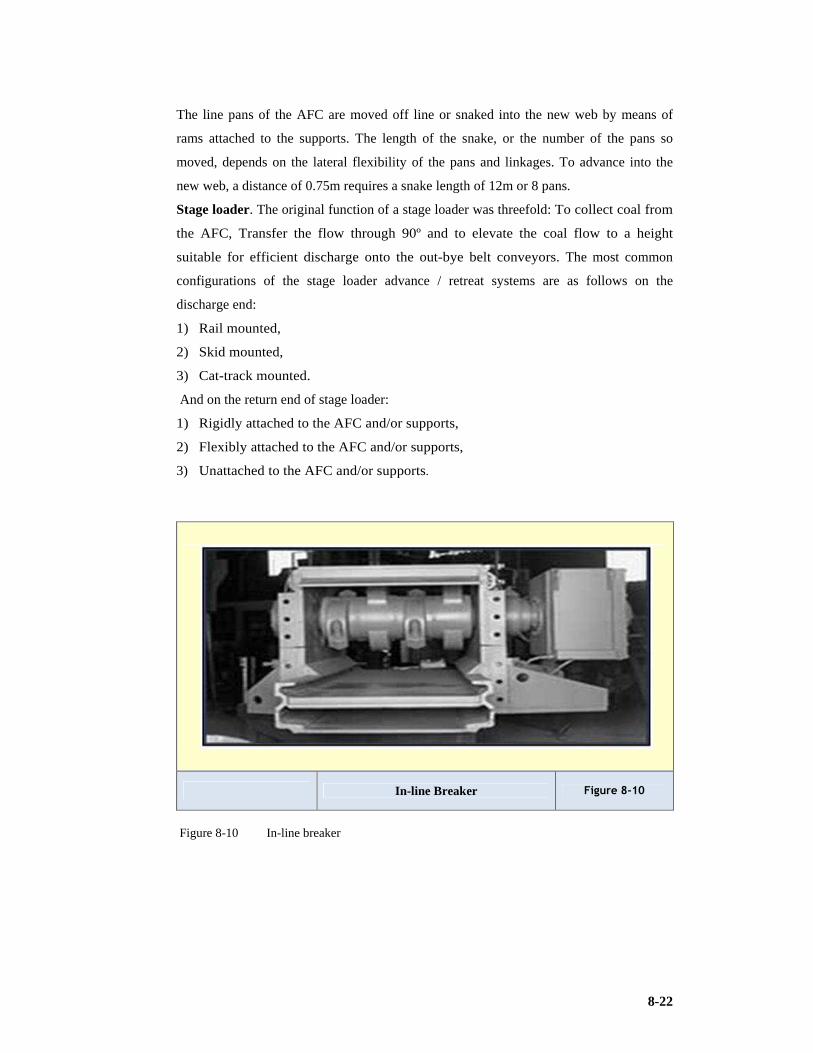
8-22
The line pans of the AFC are moved off line or snaked into the new web by means of
rams attached to the supports. The length of the snake, or the number of the pans so
moved, depends on the lateral flexibility of the pans and linkages. To advance into the
new web, a distance of 0.75m requires a snake length of 12m or 8 pans.
Stage loader. The original function of a stage loader was threefold: To collect coal from
the AFC, Transfer the flow through 90º and to elevate the coal flow to a height
suitable for efficient discharge onto the out-bye belt conveyors. The most common
configurations of the stage loader advance / retreat systems are as follows on the
discharge end:
1) Rail mounted,
2) Skid mounted,
3) Cat-track mounted.
And on the return end of stage loader:
1) Rigidly attached to the AFC and/or supports,
2) Flexibly attached to the AFC and/or supports,
3) Unattached to the AFC and/or supports.
In-line Breaker Figure 8-10
Figure 8-10 In-line breaker

8-23
Long Airdox Stageloader Figure 8-11
Figure 8-11 Long - Airdox stageloader (After Long Airdox website)
Chock shields. The supports required for high seam operations, i.e. greater than 3.0m,
would require the following basic features:
1) Structural strength
2) Easy maintenance
3) Stability, particularly if combined with gradients and/or soft floors
4) Goaf flushing protection, vital and must be 100 percent complete
Chock Shield Section View Figure 8-12
Figure 8-12 Section of a chock shield

8-24
Shield Supports (Matla) Figure 8-13
Figure 8-13 Shield supports (courtesy Matla)
The most important operational criteria governing the primary design characteristics of
supports are as follows:
1) Support resistance,
2) Support geometry and kinematics,
3) Floor contact pressure,
4) Range of seam thickness capability,
5) Stability,
6) Travelling track,
7) Hydraulic control systems,
8) Compatibility with other face equipment,
9) Maintenance requirements.
The selection of values of support resistance usually is made to fulfil one of the following
conditions:
1) To prevent excessive convergence of the roof during the supporting cycle, but
having a minimum value to induce caving at the rear edge of the support,
2) To prevent any bed separation over the face area whatsoever.
Energy and services supply. Longwall equipment requires the following energy and
services supply for normal operation: Electrical supply, hydraulic fluid supply, water
supply, compressed air and batteries.

8-25
LW Power House Figure 8-14
Figure 8-14 Remote power house
Pantechnikon Figure 8-15
Figure 8-15 Pantechnikon applied on Matla (from Matla)
8-26
8.2.6 Factors affecting the effectiveness of the longwall
operation
Face length
Face lengths for mechanised longwalls can be optimised according to the formula
developed by Uasuo Tsuruoka and Masamiti Shikasho. This formula should be considered
together with considerations of strata behaviour, which will be discussed later in this
section.
The optimum face length will be defined as the length that results in the minimum cost
per ton produced. The costs associated with longwall mining can be classified in the
following categories:
1) Variable cost directly proportional to face length (L); Depreciation cost and
maintenance cost of face supports and face conveyor,
2) Variable cost inversely proportional to the face length (L); depreciation and
maintenance costs of the face-cutting machine, gate road conveyor development costs,
and power supply costs for face equipment,
3) Fixed cost; cost of longwall face move;
Equation 8-1 Optimising wall face length
Optimizing face length with respect to cost assumes that the proportional constants are A,
B, and C the cost f(L) at a face will be dependent on the following:
Development
When considering longwall development various choices of the type of development exist.
This choice also affects production capacity and therefore productivity of such
development. If such development is of single- or double-entry type (with the advantage of
higher extraction) such development for the purpose of costs, should be considered as part of
the longwall system. If the development is similar to a normal conventional section in
terms of productivity and costs, it could be excluded in an economical comparison of
longwall versus conventional mining.
Single or multiple entry development. Normally the double-entry method is employed
in South Africa for longwall development, although the 3-entry system has been used
occasionally. Owing to retreat mining being practiced in South Africa the single entry
system has not been used.
f(L) = A*L +B*1/L +C

8-27
As an example of the effect of the entry system on the volumetric percentage extraction
obtained by longwalling, consider a 3.8m seam with a minimum height of 2.9m in which
the pillars between entries are 30m X 100m.
The percentage extraction obtained would be the following to quote Fauconier:
1) “Single-entry 76%
2) Double-entry 67%
3) Triple entry 60% (Fauconier & Kersten, 1982).
Production from a three entry system in some instances could be increased by up to 25%
compared with a double-entry system. This higher production could decrease the total
longwall mining cost by approximately 3%. Investigations currently are being undertaken
to remove or partially remove the barrier pillar.
Panel length
The breakeven point of a longwall face compared to other mining methods is normally
calculated in unit production (t/month) including longwall moves. Thus, the shorter the
panel length, the more pronounced will be the adverse effect of a longwall move. The
longest panel that has been mined to date in South Africa was 2.3km (2.0 X 10⁶t). A
panel length of 3km seems practical for the present generation of longwall equipment but
could stand further lengthening.
Equipment availability
When considering equipment availability, the use of the available time, measured in
t/minute, must be considered.
Compatibility of equipment
It is essential that all the equipment in the longwall be compatible. Capacities of various
units should be balanced.
Operational efficiencies
A number of factors can influence the operational efficiency of the longwall system, for
example:
1) “The method of cutting (bi-directional, unidirectional, half face or full face) is
determined mostly by the face length, type of equipment, and the compatibility,
which determines the ratio between cutting time and the time spent on ancillary
operations. Dust and gas emission also affects the method of cutting,
2) The rate of production is affected by the web width, cutting speed, and the
method of cutting,

8-28
3) The occurrence of large coal on the AFC often results in excessive face downtime
(up to 15%). The installation of a breaker on the shearer in one case has cut the
downtime caused by large coal virtually zero” (Fauconier & Kersten, 1982).
8.2.7 Wall mining in the Witbank and Highveld coalfields in
South Africa
Shortwall mining history is discussed by Fauconier and Kersten (1982) and identifies the
evolution of the method from the use of powered supports and a continuous miner to the
current concept of using a shearer with the powered supports, making a modern shortwall
a short longwall. The consequence of using a continuous miner resulted in face breaks as
the span from the support to the face was to large.
Longwall mining was extensively used at Sigma colliery and Coalbrooke colliery in the
Vereeniging - Sasolburg coalfield in the 1970’s and 1980’s and a thin seam derivative
was practiced at Durban Navigation colliery at about the same time. Secunda collieries
deployed as many as eight faces at one time setting numerous world records for this
method of production. New Denmark and Matla collieries soon followed with modern
faces. New Denmark was the first colliery in South Africa to be designed as a longwall
mine. Arnot colliery in the Witbank and Middleburg coalfield also had a successful run
with a longwall unit.
Shortwall mining at Matla colliery
Matla colliery is situated at Kriel in the Highveld coalfield of Mpumalanga. A modern
mega - colliery with three shaft complexes, Matla has three exploitable seams with No. 4
Seam and No. 2 Seam equipped with the wall operations. The other mineable seam is the
No. 5 Seam. Shortwall is the South African term for a short longwall.
Production ranges from 12 to 15Mt (metric) per annum using two shortwall faces and 13
continuous miner sections. As a result of an objective to reduce the cost per ton of coal
delivered to power stations by 20% in 1997 terms the mine opted for wall systems. It
must also be noted that a scepticism with regard to the success of wall mining existed in
South Africa at the time. The No. 2 Seam which is the deepest of the three seams is only
at a depth of 116m at which satisfactory extraction rates can be achieved with partial
extraction (pillar mining)(Matla Presentation, Nel J, 2006).
Hard Cutting Conditions . Matla has some of the toughest cutting conditions in the
world. The coal has a UCS of between 20 to 35MPa (Average 25MPa). Random in-seam
floating stone of 70 to 140MPa strength is very often found. The 4 seam operation
requires a specific energy of cutting of 0.35 to 0.45kWh per tonne (metric).

8-29
The coal seam displays a low jointing and cleat density average of 0.4cleats/m and
21cleats/m respectively. There is a low stress environment with the pillars and face
displaying (Matla Presentation, Nel J, 2006):
1) No Spalling
2) High abrasivity ( 300 – 400mgFe)
It should be noted that the shearer displays in this environment (Matla Presentation, Nel J,
2006):
1) Typical pick consumption (114t/pick)
2) Max Cutting Speed (Full Face Bi-Di) = 7m/min
Matla claims low development costs. The mine quantitatively designs the optimum face
length based on NPV and IRR criteria. The optimum face length is given as 127m.
The product homogenising objective requires blending No. 2 and No. 4 Seam coal. The
mine claims that this action restrains production.
Disadvantages of a short face (Matla Presentation, Nel J, 2006):
1) “High Development Rate Required
2) Increased Frequency of Face Moves
3) More Advance Cycles Per Tonne
4) More Arduous Shearer Duty Cycle” (Matla Presentation, Nel J, 2006).
Advantages of a short face:
1) “Simpler Face Steering
2) Ease of Maintenance
3) High Face Advance
4) Less arduous loading on belt conveyors
5) Improved equipment repair process” (Matla Presentation, Nel J, 2006)
The Matla 4 Seam face equipment consists of:
1) DBT Supports and AFC
2) JOY 06LS05 Shearer
3) Nepean Conveyor Drives

8-30
Improved Equipment Repair
Matla Stratigraphy Figure 8-16
Figure 8-16 Matla stratigraphy (from Matla)
Determination of Optimum Face Length (Intersection of NPV & IRR Curves)
Figure 8-17
Figure 8-17 Determination of optimum face length (Matla Presentation, Nel J, 2006)

8-31
The cut length of the face is 121m between gate roads. The maingate and tailgate are
designed to a width of 7.2m. Width of gate belt conveyor = 1,350mm at 35° trough angle.
The shearer has the following specifications (Matla Presentation, Nel J, 2006):
1) “Total installed power = 1,500kW
2) Power to ranging arm = 610kW
3) Nominal haulage pull = 690kN
4) Drum diameter = 2,286mm
5) Web depth = 1,000mm
6) Machine mass = 78t (86 UST)
7) Haulage type = Ultra Track (Matla Presentation, Nel J, 2006)”
Matla Wall Panel Layout Figure 8-18
Figure 8-18 Matla panel layout (Matla Presentation, Nel J, 2006)
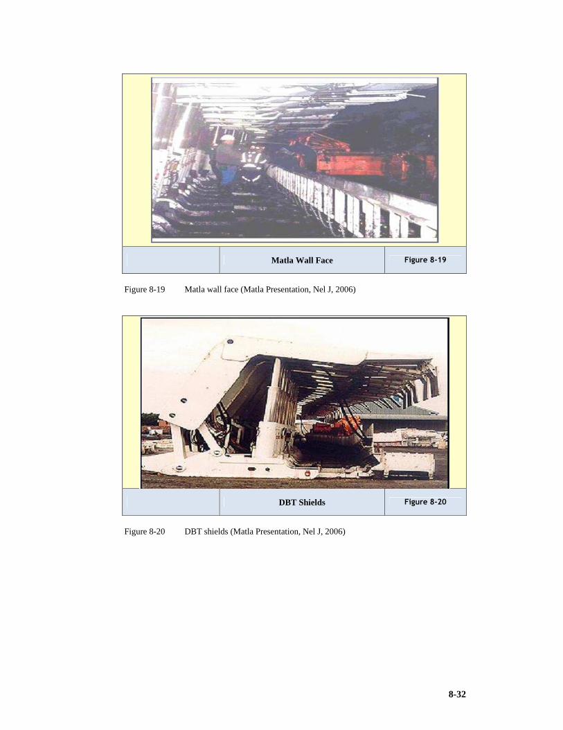
8-32
Matla Wall Face Figure 8-19
Figure 8-19 Matla wall face (Matla Presentation, Nel J, 2006)
DBT Shields Figure 8-20
Figure 8-20 DBT shields (Matla Presentation, Nel J, 2006)

8-33
Joy Shearer Figure 8-21
Figure 8-21 Joy shearer (Matla Presentation, Nel J, 2006)
Production results. Monthly Production of 496,000t as best achievement was recorded.
Production Results Figure 8-22
Figure 8-22 Production results for various panels (Matla Presentation, Nel J, 2006)
Vital statics of the Matla face (Matla Presentation, Nel J, 2006):
1) “Pick changing time 20 to 120minutes. 2) Engineering availability = ±92%.

8-34
3) System utilisation = ±53%.
4) Face move duration (2 per annum) = 25 to 35days. Limited by shearer overhaul time”
(Matla Presentation, Nel J, 2006).
Longwall mining at New Denmark colliery
New Denmark colliery is an Anglocoal operation based in Standerton, situated about 180
southeast of Johannesburg and was designed as a wall mining operation. Modern best
practice systems were chosen and implemented.
New Denmark Colliery (NDC), broke a new South African low seam longwall record of
464,095t (tonnes) using Joy machinery in August 2004. The mining height ranges from
1.5m to 2.1m with an average of 1.8m. Planned as a total longwalling operation,
production at NDC commenced in 1982, and by the early 1990’s the mine was running
two longwall and two shortwall districts at two shafts, namely Central and North, the
latter of which was commissioned in 1986. Currently, the mine has consolidated
operations at Central shaft, with North shaft being closed, and a new area serviced by
Okhozini shaft being developed. The one remaining longwall operating at Central shaft
has performed indifferently since installation in 1996, and was subjected to a joint
intensive care programme commencing in 2002. The latest of these records was 464,095t
achieved in August 2004. In addition, three daily records and one weekly record, on two
10-hour shifts per day, were broken in achieving the result. A mechanised 200m deep
underground coal mine, NDC is one of the deepest coal mines in South Africa. Main and
secondary development is done using continuous miners. The bulk of the production is
sourced from one total extraction unit, using longwall mining methods. With a No.4
Seam bituminous coal reserve in excess of 300Mt, the expected life of the mine is more
than 40 years, depending on power demand from the southern African region (Personal
communication, Marais W, 2009). A new face has recently been installed (2010) but this
has as yet not improved on production deliveries (Personal communication, Marais W,
2010).
8.2.8 Longwall mining in China
Shendong Colliery
Equipment deployed. The colliery uses the following equipment (Shendong
presentation, Coaltech, 2004):
1) Miner: Joy 6LS5 equipped with a 610kw per cutter drum and cuts a 0.865m web to a
cutting height of 2.2 to 5.0m.

8-35
2) AFC: 2,200tph and is 250m long by 1m wide using 700kw drives for main and tail.
3) 143 Shields: 2 legs - 5m high x 1.75 centres, 777t rated.
4) Stage loader and impact crusher.
Production results. Various shafts at the colliery delivered the following tonnages
(Shendong presentation, Coaltech, 2004):
Chinese Localities Figure 8-23
Figure 8-23 Chinese localities (from Coaltech)

8-36
Table 8-2 Production at Shendong Mine Complex. (Shendong presentation, Coaltech,
2004)
Mine 2001
Mtpa
2002
Mtpa
2003
Mtpa
Daliuta Complex
(2 longwalls and 4 miners)
15.12 16.25
20.20
Daliuta Longwall 7.73 8.74
7.60
Huojitu Longwall 5.28 5.04 8.40
Yujialiang Mine
(1 longwall and 2 miners)
6.62 10.59 11.00
Yujialiang Longwall 5.62 8.65 8.40
Bulianta Mine
(1 longwall and 2 miners)
5.12 7.60 9.00
Bulianta Longwall 4.80 6.96 8.30
Kangjiatan (Sunjiagou) 1.08 2.80 8.00
Kangjiatan Longwall 1.30 6.80
8.2.9 Australian longwall productivity
Baird (2008) a consultant with McAlpine-B, reported that Australian longwall mines have
increased productivity by 12% over the past five years. The question is posed that while
longwall tonnes have increased by 13% from 73.4Mt in 2002 to 84.2Mt in 2007, what has
happened with all important longwall productivity? According to analysis of coal data
there was a 12% increase in productivity in Australian longwalls between 2002 and 2007
in line with increase in production.
Productivity is defined by expressing output as a ratio to selected inputs. In previous
years, longwall productivity was expressed as the ratio of longwall tonnes per employee
at the mine (tons/man). This however is not the most important productivity measure as
the variation of capital investment is not taken into account. “Instead productivity is
reviewed in terms of longwall operating hours and nameplate capacity” (Baird, 2008).
“Baird stated, “One of the difficulties in calculating productivity of Australian longwalls
is that there is significant variability in longwall operating time. Naturally increasing the
number of operating hours increases output. In 2002 there were more five day operations
in place, like Cumnock No.1 and Elouera, than in 2007” (Baird, 2008).
Overall there was a 13% increase in longwall operating hours in 2007 compared to 2002.
It would be necessary to look at metric longwall tonnes per operating hour (t/hr) to assess

8-37
productivity. Using this productivity increased by 16% between 2002 and 2007 (Baird,
2008).
A longwall system is a complex process. To assess nameplate capability requires a
measure of how many tph a longwall is capable of producing. Phillips reported that it is
usually AFC capacity that is the limiting factor(Personal communication, Phillips, 2010).
The installed shearer power is used as a proxy for nameplate capability. Based on this
calculation installed shearer power increased by 23% between 2002 and 2007. Therefore,
an increase in output is expected simply because of increased nameplate capacity. To take
into account the increased capacity of the system, the metric longwall tonnes per
operating hour per kilowatt of installed shearer power is used as a measure of overall
longwall productivity (t/hr/kW).
Baird reported, “In total, longwall output has increased by 13% between 2002 and 2007.
Part of the increase is due to longer operating hours and increased nameplate capacity, but
a significant proportion is due to increased productivity. This increased productivity is
likely to result from increased availability and increased utilisation”.(Baird, 2008).
Wall mining in New South Wales
The Hon. Ian Macdonald, MLC, Minister for Mineral Resources states in the 2008 NSW
Coal Industry Profile, NSW Department of Primary Industries: “The unprecedented coal
mining boom in NSW has brought new investment and created jobs in regional areas as
well as increased export income to the state with coal the number one export in value
terms worth an estimated Aus$6.2billion in 2006-07. The value of NSW coal production
is predicted to increase to around $9.4 billion in 2007-08 on the back of significantly
higher coal prices. Direct employment in NSW coal industry at June 2007 was 13,392
representing 66% of the states full time mining employment. The NSW coal industry
attracts significant international investment because the state has: Major secured
recoverable coal reserves – over 12Bt, high quality export thermal and coking coals,
stable regulatory environment and supportive government, well established infrastructure
– rail, ports and power. NSW mines has one of the most enviable mine safety records in
the world. The mining industry meets contemporary standards for environmental
management and continues to support sound environmental practices, including the
development of new clean coal technologies to curb greenhouse emissions”(Macdonald,
2008).
The coalfields in NSW are:
1) Hunter coalfield
2) Newcastle coalfield

8-38
3) Western coalfield
4) Southern coalfield
5) Gunnedah coalfield
The NSW mix by mining method of coal production amounted to in the specific decades:
Table 8-3 Mining Method Mix NSW (Macdonald 2008).
Method 1987 1997 2007
Bord & Pillar % 33 9 4
Longwall % 25 35 30
Opencut % 42 56 66
Currently Pillar extraction is not widely practiced and that the favoured underground
method is wall mining with the proportion from surface methods expanding over the past
decades and currently making up two thirds of coal production.
Productivities during 2006-07 amounted to 9,000 saleable t/employee for underground
and almost 18,000 saleable t/employee from opencut. Coal exports from NSW during
2006-07 amounted to 91.5Mt (20.4Mt, 22% metallurgical coal and 71.1Mt, 78% steam
coal).
Table 8-4 Summary of coal statistics for NSW (Macdonald, 2008)
Production ‘000 t 2005-06 2006-07
Raw coal 161,140 170,324
Underground 52,232 57,241
Saleable coal 124,611 131,334
Underground 42,297 46,202
Number of mines 58 60
Underground 30 29
Employment 12658 13392
Underground 6,541 6,792
This researcher conducted a study tour of NSW and Queensland. The Focus in NSW was
around the Singleton area in the Hunter coalfield where the Bulga and Cook complexes
were visited. Xstrata’s Bulga has the Beltana operation which has developed a reputation
for productivity. The Cook operation of Caledon Resources was looking at ways of

8-39
improving gate road development through the application of Continuous Haulage
systems. The specific system implemented is the Magatar Linear Mining Method.
Beltana Colliery
Gary Cambourn, Operations Manager for Beltana Highwall Mining was interviewed and
responded to the research questionnaire. The most striking characteristic is that the
longwall face lengths tend to 400m while the optimum panel length is set at about 3,000m
as this is optimised as a function of shearer overall intervals. The productivity advantage
is not achieved through mining height as the height is at medium seam thickness at 3m. It
is apparent that profile is not as critical in the medium to high faces(Personal
communication, Camborne, 2008).
Table 8-5 Australian Production Statistics (After Australian Longwall Magazine)
Mine State Longwall Other Total
Angus Place NSW 3,016,900 191,600 3,208,500
Appin / Appin West NSW 1,613,400 334,200 1,947,600
Ashton NSW 2,569,700 335,100 2,904,800
Austar NSW 1,363,500 142,100 1,505,600
Baal Bone NSW 1,734,600 187,700 1,922,300
Beltana NSW 7,144,000 705,500 7,849,500
Broadmeadow Qld 3,410,700 148,900 3,559,600
Bundoora Qld 1,142,000 76,000 1,218,000
Crinum Qld 3,860,500 284,900 4,145,400
Dendrobium NSW 3,230,600 388,400 3,619,000
Grasstree Qld 3,408,000 435,000 3,843,000
Integra (Glennies Creek) NSW 2,732,100 223,800 2,955,900
Kestrel Qld 4,461,500 298,600 4,760,100
Mandalong NSW 4,360,400 406,900 4,767,300
Metropolitan NSW 1,124,000 360,000 1,484,000
Moranbah North Qld 4,052,000 496,000 4,548,000
Newlands Northern Qld 4,593,200 301,700 4,894,900
Newstan NSW 2,657,800 50,300 2,708,100
North Goonyela Qld 2,290,100 136,200 2,426,300
Oaky Creek No.1 Qld 5,917,000 339,500 6,256,500
Oaky North Qld 5,015,300 325,500 5,340,800
Ravensworth (Newpack) NSW 806,200 290,600 1,096,800
Springvale NSW 2,836,100 166,300 3,002,400
Tahmoor NSW 1,675,200 249,700 1,942,900
Ulan NSW 2,876,400 488,700 3,365,100
United NSW 3,102,000 301,100 3,403,100
Wambo North NSW 1,168,200 309,000 1,478,100
West Cliff NSW 3,049,900 322,800 3,372,700
West Wallsend NSW 1,663,900 443,000 2,106,900
8-40
A series of 11 panels have been sequentially mined using one set of face equipment with
appropriate replacement and refurbishment. The maingates and tailgates commence in the
box cut with trunk infrastructure outside in this box cut perpendicular to which the panels
are developed. High standards of housekeeping are evident. Labour and manpower is at a
minimum. Personnel are highly skilled, very literate and multitasked (Personal
communication, Camborne, 2008).
Camborne reported, “Beltana produces between 5.5 Mtpa and 7.5Mtpa with this one face.
They use a high powered 7LS6 Joy shearer” (Personal communication, Camborne, 2008).
Queensland Operations
Capcoal
Capcoal operates three underground mines, and an open cut mine. Lake Lindsay is under
construction as part of the Capcoal Expansion Program (2008). Approximately 600
people are employed at Capcoal. Capcoal is located in the heart of the Bowen Basin in
Central Queensland, 25 kilometres south-west of Middlemount (population 3,000) and
200 kilometres south-west of Mackay. It also is within a comfortable driving distance of
the major regional cities of Emerald and Rockhampton (Johnson, 2008).
Capcoal mines 11.8Mt of coal annually to produce in excess of 8.5Mt of prime quality
hard coking coal and PCI coal. After processing, coal is transported 360 kilometres north-
east by rail to the Dalrymple Bay Coal Terminal for export.
Mining leases controlled by Capcoal cover 27,343 hectares and estimated coal resources
are in excess of 1 billion tonnes, with in-situ mineable reserves of 125Mt. Capcoal
exports to steel manufacturing customers in East, South and West Asia, Europe and Latin
America.
Capcoal is owned by Anglo Coal Australia (ACA) (70%) in a joint venture with Mitsui
Coal Holdings Australia (30%). The mine is operated and managed by ACA (Anglo Coal
Australia).
The majority of Capcoal employees reside in Middlemount, which has good educational,
community and sporting facilities. Apart from mining, the main industries of the region
are cattle and grain crop farming.
Capcoal has continued to meet its commitment to subsidence rehabilitation to be half a
panel behind mining at any one time. The operation also is involved in numerous
programs and studies relating to biodiversity and environmental management initiatives
(Johnson, 2008).

8-41
Ongoing interaction with the local community is maintained through a range of formal
and informal communications.
The Capcoal Mining Skills Development – Middlemount Community School initiative
established in 2004, along with other education and training programs, has achieved good
results and received excellent community feedback. Capcoal also is a regular contributor
of direct financial and other aid to local community organisations. A Cultural Heritage
Management Plan (CHMP) has been established between Capcoal and traditional owners
(the Barada Barna Kabalbara and Yetimarla People) (Johnson, 2008).
German Creek Mine is located 240 kilometres south–west of Mackay in the Bowen Basin
coalfields of Central Queensland. The complex comprises three underground mines
Southern Colliery, Central Colliery and Grasstree Mine and the Oak Park Opencut Mine.
Capcoal also operates the adjoining Opencut mine for joint venture owners Anglo Coal
Australia (86%) and Marubeni (14%).
The majority of coal is mined from the German Creek Formation, noted for containing
hard coking coal of exceptionally high quality. The German Creek Sequence contains five
intervals known as the German Creek, Corvus, Tieri, Aquila and Pleiades seams
(Johnson, 2008) .
Run-of-mine (ROM) coal is processed in a centrally located Coal Handling and
Preparation Plant prior to being transported by rail to the Dalrymple Bay Coal Terminal
for export. The underground operations at German Creek Mine comprise of Southern and
Central Collieries and Grasstree Mine. The underground mines utilise efficient
technologically advanced longwall mining methods for cost effective coal extraction.
Each mine operates independently with its own organisation, infrastructure, services and
equipment. Continuous miners are used to develop underground roadways and headings
in the coal seam to create panels of coal to be extracted by the longwall mining system.
Typically each panel is 250m across, between 2.6m and 3m high and is up to 3km long
(Johnson, 2008).
Grasstree Colliery. Grasstree is equipped for (Capcoal Presentation, Johnson E, 2009):
1) 2008 Production of 4Mt
2) Grasstree serviced via Shaft/Winder system
3) Personnel & Equipment shaft (main intake)
4) LW Blocks from 1.7km to 3.9km
5) Hole-through into Southern Colliery (Grasstree West)
6) Heavy vehicle access via highwall portal
7) Established coal clearance system

8-42
8) Gassy environment >9m3/t outburst risk. Managed by inseam / MRD drilling.
9) Longwall specific emission 14-16m3/t
10) Current depth of operations 200-450m
It operates as one of the Capcoal underground collieries focusing on longwall mining. one
of the areas visited by this researcher during the 2008 study tour. Figure 8-24 depicts the
portal structure developed from a highwall. This is for access to a partial extraction or
bord and pillar operation Aquila colliery associated with Capcoal.
Bundoora Colliery. Mine Design incorporates two longwall panels which are accessed
from the highwall of Pit C. Capcoal developed this mine to bridge the gap between
Central and Grasstree Mines (Johnson, 2008).
Reduced manning was being implemented due to reduced off take capacity from mine. Operation limited to a longwall or development in sequence. Management were
proposing the extension of two additional panels.
It is here that the researcher observed a wall face manned with only 3 people.
Management commented that this was not ideal but a consequence of short term labour
absenteeism (Johnson, 2008).
Moranbah North Colliery
Livingstone-Blevins (2008) stated in an interview report: “Moranbah has become a case
study in powerful face support application. At the time of the researchers visit in
November 2008, Moranbah had taken delivery of 35 by 1750tonne, 2m wide Joy Mining
Machinery roof supports as the first part of a onsite mini-build and compatibility testing
as it prepared to head underground for installation in the second quarter. The roof
supports, the biggest in the world, will be part of Moranbah’s new 151 shield face which
it hopes will combat the yielding and roof fall incidents it has suffered in the Goonyella
Middle seam. The installation will be carefully watched by the longwall industry
worldwide as Moranbah rises to the challenges of installing, operating and moving the
massive supports. But most importantly, the industry watches to see if the powerful
supports will combat the strata issues at the mine. Anglo Coal Australia’s regional
engineering and maintenance manager Peter Van de Ven, has been an integral part of the
extensive design and specification team for the powerful supports.
Strata issues in the Goonyella Middle seam are nothing new for the mine or other
adjacent mines operating in the seam. Moranbah North started extracting from the seam
in 1999. The depth of cover at the mine varies significantly as the seam dips down into
the 100 series panels. With the increase in depth has come significant yield problems for
the roof supports with cavities forming on the face and resultant roof falls. The present

8-43
face suffers from being in yield far too often and it was getting progressively worse the
deeper the mine got. With the 980t rated supports the face was yielding 40 to 50% of the
time with support leaning issues, equipment damage and recovery operations. The slower
the face goes through the ground, the more load it attracts, the worse conditions become.
Moranbah in 2004 purchased 25 by 1200t-rated supports which were initially installed at
the mid-face. While a “localised” improvement was noticed compared to the previous
supports, the 1200t supports had limited overall impact. Management estimated the
supports reduced yield time from 40 to 50% to 10 to 15%. This is still an unacceptable
level.
Van de Ven told delegates at the Australian Longwall Mining Summit in June 2008 as
quoted by Livingstone- Blevins. “We then went and asked how much bigger do we have
to go? And that’s how we came up with a 1750tonne, 2 metre wide support.” Anglo
adopted a wide-ranging process to determine the Powered Roof Support (PRS) or shield
capacity. They looked at historical databases for similar conditions and equipment, and
spoke to original equipment manufacturers for their expertise. The team used strata
interpretation and computer modelling techniques, looking at ground reaction curves
(finite element analysis, FE analysis) and displacement modelling and the Citect and
Optimate Faceguard interpretation. Underground face cavity mapping was also used,
together with other expert’s opinions. During the review process consultants – Australian
Mining Consultants and Mining Consultancy Services – were used to do the modelling
work and the PRS review. Interpretation work was also done to attempt to predict how
the roof and supports would behave in future panels, and the Citect data with 3D
modelling to confirm the requirements and assessment. Optimate’s Faceguard software
was used to validate the modelling. According to Moranbah North general manager Tim
Hobson, members of the workforce were also involved with the design of the supports.
The final specifications for the Joy supports were determined at 1,750t yield rated,
2,050mm centres with 480mm leg cylinders. The roof supports each weigh 61t, with the
gate end supports coming in at 64t. The supports have a height range of 2.4m to 5m and
are controlled by Joy’s RS20s control system. Sprag plates on the shields were also
specified. Van de Ven said consultants WBM were brought in to carry out a full finite
analysis review of Joy’s design. The supports were put through a 90,000 cycle testing and
while there were some initial issues at testing stage, the final design of the supports
passed the test program. The new face has been made Mines Department standard
instruction (MDG41) compliant with hydraulic hoses sleeved, individually tagged and the
high-pressure hoses restrained. Other enhancements include RS20’s control system for

8-44
the supports and the use of JOY’s FACEBOSS system and the LASC automation system
(Longwall AFC and Shearer Control).
Along with the 151 roof supports (expected in January 2009) for the 308m Moranbah
North face, Anglo has also placed orders for two Joy 7LS6 shearers with LASC
automation capability; two matching Joy 2.05m wide AFCs rated at 4500tph with 50mm
Broadband chain. The AFC will be powered by three 1,000 kilowatt maingate and tailgate
drives. The new equipment will be mated with recently purchased Joy mining crushers
and a pair of Longwall hydraulic pump stations” (Livingstone-Blevins, 2008).
Moranbah North Powered Roof Support project manager Johan Laubscher said “the mini-
build started onsite mid-year when 34 supports were used with the new maingate, tailgate
and pan line. The final assembly of the drive components are currently in progress and
connecting the supports to the AFC is the next task. Once the shearer arrives in
September it will be assembled and put on the pan line.
The next step after this is to obtain the pump stations and more that is currently being
used underground in LW201 after the longwall move is completed and assemble this with
the new equipment to complete the longwall system. Compatibility testing will then
commence with completion scheduled by end of December 2008. The training of the
crews will start in December and be completed by February 2009 on the mini-build
equipment” (Laubscher, Personal communication, 2008).
Livingstone-Blevins added, “Once the new face is up and working, its performance will
be monitored through CITECT (displacement modelling) application software, plus the
mine will look at the availability and utilisation of the equipment” (Livingstone-Blevins,
2008).
“The only additional purchase the mine is currently investigating is for a monorail. To
move the massive supports, Moranbah was required to buy a special longwall move fleet,
capable of hauling the 64t supports. Currently the largest shield haulers on the market
handle up to about 50t. Industrea Mining Equipment (formerly Boart-Longyear) secured
the contract to supply the dedicated fleet, which includes five purpose-built 70t roof
support carriers, two 70t mine dozers and two 70t electric retrievers. Laubscher said, “the
manufacturing of the transport equipment was progressing well with the first of the five
carriers on wheels late in August and undergoing initial testing. All five carriers will be
delivered to site in January 2009 and fitted with an additional lifting plate arrangement.
The first dozer is expected at the end of January 2009 and the second to arrive in April.
The two retrievers have a scheduled delivery of June 2009”. On an operational level with
the new longwall the biggest challenges will be installation and retrieval of the supports

8-45
and catering the roadways, intersections and the install and take-off roads for the bigger
supports.
Maintaining the big supports will be the issue when it comes to change out of components
like the legs, which weigh almost 4t each. Training packages are put together which will
include videos to show how these special tasks need to be performed. There are also
provisions made on the shearer to have a special carry arrangement, and specific lifting
points were designed into the support’s canopy to cater for the heavy lifts.
The existing 980 to 1,200t longwall supports at Moranbah North are currently operating
in the relatively shallow 200 panels instead of the deep 100 panels.
They are extracting four short panels in the 200 series, while they wait for the new
longwall to arrive. When the new equipment is installed it will operate in the deeper 108
panel and then alternate North-South with the deep 600 panels. The old longwall
equipment will continue operating in the shallow 200 series panels. With the two faces,
the mine plans to operate a walk-on, walk-off schedule, where the new and old faces
alternate operation with the crew simply switching panels once completed. Moranbah
planned to commission the new face ahead of finishing the previous face but they will not
generally run at the same time as the belt system won’t allow two faces together. They
will go from multi-week changeovers to walk-on, walk-off. This process will continue for
the next three to four years until the 200 series panels are completed and the old face
equipment is retired” (Livingstone-Blevins, 2008). Tables 8.4 and 8-5 give Australian
wall statistics.
Aquila Highwall Mine Figure 8-24
Figure 8-24 Aquila highwall entry (Capcoal Presentation, Johnson E, 2009)
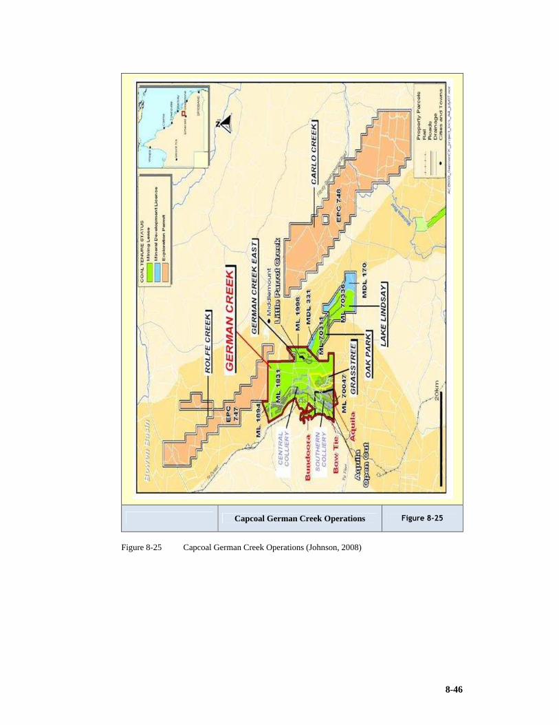
8-46
Capcoal German Creek Operations Figure 8-25
Figure 8-25 Capcoal German Creek Operations (Johnson, 2008)

8-47
8.3 Wall Mining Capital and Operating Costs for an Energy Project
A Financial Model for a project dealing with medium grade 21MJ/kg CV Coal and
Uranium bearing carboniferous shales presented the following cost structure (Macdonald,
2010).
The uranium mineralisation in the Springbok Flats occurs almost exclusively within the
Warmbad Formation (or Upper Ecca) of the Karoo Supergroup, associated with
carbonaceous shale and bright coal in the Lower Middle coal seam at the top of the
sequence, referred to as the “Coal Zone”. Uranium resources are calculated over a
constant 1m thickness located at the top of the Coal Zone, consisting mainly of
carbonaceous shale with subordinate interbedded coal bands.
A geological model was built by Gemecs (Pty) Ltd using the historical and twin borehole
data. This model was reviewed by SRK and an Inferred Mineral Resource estimate was
declared according to the SAMREC Code. Conceptual mine plans using longwalls
(“LWs”) and continuous miners (“CMs”) were designed by MRM Mining Services (Pty)
Ltd (“MRM”) for the uranium in the Uranium and Power Project. The conceptual
underground mine design assumed conventional longwall production with development
by two CMs supporting one LW. The development was planned on a constant 3m horizon
for ease of access and ventilation purposes. Two configurations for the LW equipment
were considered: a single 3m cut of the carbonaceous shale and underlying coal, or a 1m
top cut of the carbonaceous shale, followed by a 2m bottom cut on retreat of the
underlying coal.
Access to the underground mine considered a down cast conveyor decline with road
access next to it from surface down to the “reef/seam” intersection. A raise bore hole
drilled in close proximity to this intersection point would act as an up-cast shaft with fans
on surface. A blind-sink down cast vertical shaft sunk approximately 4km to the west
along the main development would provide for quick personnel access.
The Uranium and Power Project entails a mine, power station and uranium recovery plant
designed to treat 1.3Mtpa of carbonaceous shale and 1.5Mtpa of coal, at an average CV
of 17.7MJ/kg.

8-48
Table 8-6: Mining Capital Costs (from Macdonald, 2010)
Mining Capital Scource of capital estimate Capital Cost (Rmillion)
Vertical shaft 1 (350m deep) Recent written quote from Shaft Sinkers (Dec 2010)
62.5
Vertical shaft 2 (400m deep) Recent written quote from Shaft Sinkers
71.5
Conveyor decline Recent written quote from Shaft Sinkers
75.6
LW equipment (per LW) Recent written quote from Joy (Sept 2010)
479.0
U/G equipment (per CM section) Recent written quote from Joy 49.6
Sundry equipment Recent written quote from Shaft Sinkers
3.5
Materials handling (per unit) Recent written quote from Shaft Sinkers
8.8
Shaft infrastructure (per shaft) Recent written quote from Shaft Sinkers
50.0
Ventilation – raise bore hole/fans Recent written quote from Shaft Sinkers
18.1
The Joy low profile 7LS1A shearer was considered. The 7LS6C is a medium to high
profile Shearer and has application where coal and carboniferous shales are considered
being mined together (Macdonald, 2010).
Table 8-7: Mining Operating Costs (from Macdonald, 2010)
Item Source of operating cost estimate
Operating Cost (R/t RoM)
LW mining Typical cost in 2008, escalated to 2010 terms
72.39
CM section development Typical cost in 2008, escalated to 2010 terms
87.39
Tables 8-7 and 8-7 estimated mining capital and operating costs respectively and Tables
4-10 and 4-11 the processing costs for this unusual situation.
Table 8-8: Processing Capital Costs (from Macdonald, 2010)
Processing Capital Source of capital estimate Capital Cost Rmillion
Steam Coal crushing plant Typical cost in 2008, escalated to 2010 terms
29.4
Uranium Processing plant Budget price in 2008, escalated to 2010 terms, adjusted for reduced ash treatment capacity
635.6
Power Generation Bateman quote in 2008, escalated to 2010 terms, adjusted for increased generating capacity of 664MW
8 494.5
CFB boiler plant Bateman quote in 2008, escalated to 2010 terms, adjusted for increased generating capacity of 664MW
618.2

8-49
Table 8-9: Processing Operating Costs (from Macdonald, 2010)
Item Source of operating cost estimate Units Operating Cost
Coal crushing Coal crushing plant cost – variable
Typical cost in 2008, escalated to 2010 terms
(R/t RoM) 2.90
Coal crushing plant cost – fixed
Typical cost in 2008, escalated to 2010 terms
(Rmillion p.a.) 14.1
CFB & IPP
CFB operating cost Bateman quote in 2008, escalated to 2010 terms
(R/MWh) 26.27
Power generation cost Bateman quote in 2008. Escalated to 2010 terms
(R/MWh) 61.30
Uranium recovery
Acid cost US$65/t at ZAR7.50=US$1.00
(R/t ) 487.50
Acid consumption (controlled by CFB temperature)
Formula driven (t/t ash) 0.3664
Uranium recovery plant Cost – variable
Typical cost in 2008, escalated to 2010 terms
(R/t ash) 48.87
Uranium recovery plant Cost – fixed
Typical cost in 2008, escalated to 2010 terms
(Rmillion p.a.) 106.6
8.4 Conclusion
1) This chapter has identified the application of wall methods that enable productivity
improvements. The research has identified preferred layouts and systems
internationally with direct focus on Australian Longwall Mining which is their
preferred method.
2) The research also considered Matla and New Denmark in South Africa who delivered
at world class standard.
3) The Sendong operation in China is an interesting case study of the scale of large
Chinese operations which also delivered at world class levels.
4) The modular Australian mines with highwall entries and the accent on portability is
finding favour with many mine developers.

9-1
9 PARTIAL EXTRACTION, PILLAR EXTRACTION AND PARTIAL PILLAR EXTRACTION METHODS
9.1 Bord & Pillar Mining Using Continuous Miners
9.1.1 Overview of current mining operations in the Witbank and Highveld coalfields
Lind (2004) reports that, “In general coal mining conditions in South Africa are
favourable and the seams currently mined are thick, shallow lying and undisturbed over
considerable areas. Approximately 80% of production comes from the Witbank and
Highveld coalfields. Virtually the whole of the Witbank and Highveld coalfields have
been disturbed by high strength dolerite dykes, which have also resulted in the formation
of overlying sills of the same material. The spacing of the dykes is large enough to allow
sensible planning of production panels, considerable tonnages of coal have been degraded
due to devolatilisation and burning at the time of intrusion. This is confirmed by Coetzee,
(1985).
These mining conditions allow large areas to be extracted by surface mining techniques,
while the deeper portions are amenable to mining by a wide variety of underground
techniques. The 1990’s production split between surface and underground mining
resulted in almost equal portions being mined by each method, (Willis & Hardman,
1997).
A unique feature in the development of the South African coal mining industry has been
the concept of ‘captive’ or ‘tied’ collieries, where power utilities and coal to oil
conversion plants have been constructed on or near dedicated coal reserves. This has led
to very large individual coal mines.
Underground coal production in South Africa comes mainly from bord and pillar mining.
While other mining methods, involving a greater degree of mechanisation, have been
tried, two factors have ensured the pre-eminence of the bord and pillar method:
1) The ratio of cost of equipment to cost of labour has traditionally been higher in South
Africa than in countries such as the USA or Australia, while that may have changed
in recent years.
2) Nearly all the major coal deposits are intersected by high strength dolerite dykes. Not
only does this severely limit the number of locations where longwalls could be
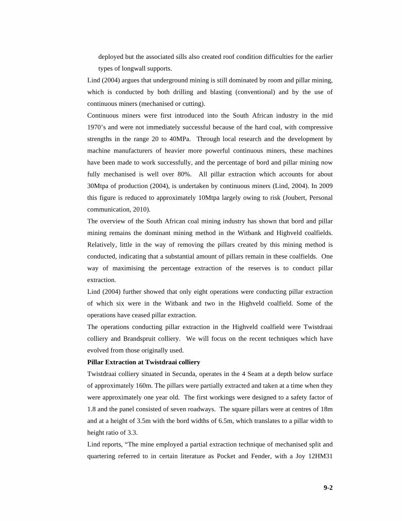
9-2
deployed but the associated sills also created roof condition difficulties for the earlier
types of longwall supports.
Lind (2004) argues that underground mining is still dominated by room and pillar mining,
which is conducted by both drilling and blasting (conventional) and by the use of
continuous miners (mechanised or cutting).
Continuous miners were first introduced into the South African industry in the mid
1970’s and were not immediately successful because of the hard coal, with compressive
strengths in the range 20 to 40MPa. Through local research and the development by
machine manufacturers of heavier more powerful continuous miners, these machines
have been made to work successfully, and the percentage of bord and pillar mining now
fully mechanised is well over 80%. All pillar extraction which accounts for about
30Mtpa of production (2004), is undertaken by continuous miners (Lind, 2004). In 2009
this figure is reduced to approximately 10Mtpa largely owing to risk (Joubert, Personal
communication, 2010).
The overview of the South African coal mining industry has shown that bord and pillar
mining remains the dominant mining method in the Witbank and Highveld coalfields.
Relatively, little in the way of removing the pillars created by this mining method is
conducted, indicating that a substantial amount of pillars remain in these coalfields. One
way of maximising the percentage extraction of the reserves is to conduct pillar
extraction.
Lind (2004) further showed that only eight operations were conducting pillar extraction
of which six were in the Witbank and two in the Highveld coalfield. Some of the
operations have ceased pillar extraction.
The operations conducting pillar extraction in the Highveld coalfield were Twistdraai
colliery and Brandspruit colliery. We will focus on the recent techniques which have
evolved from those originally used.
Pillar Extraction at Twistdraai colliery
Twistdraai colliery situated in Secunda, operates in the 4 Seam at a depth below surface
of approximately 160m. The pillars were partially extracted and taken at a time when they
were approximately one year old. The first workings were designed to a safety factor of
1.8 and the panel consisted of seven roadways. The square pillars were at centres of 18m
and at a height of 3.5m with the bord widths of 6.5m, which translates to a pillar width to
height ratio of 3.3.
Lind reports, “The mine employed a partial extraction technique of mechanised split and
quartering referred to in certain literature as Pocket and Fender, with a Joy 12HM31

9-3
continuous miner (from which the dust scrubber had been removed) and three modified
16t shuttle cars. The panel operated in good conditions with a competent sandstone roof
on a 90º extraction line (normal to the main panel axis). There was little evidence of
surface subsidence. The sizing of the coal obtained was reported to be similar to the size
obtained during primary operations (development).
A two shift operation, utilising a manpower complement of 11 people per shift produced
a consistent 3 month average production of 50,000tpm. Specialised training and a code
of practice ensured there was no loss of life.The operation was reported to have a lower
operating cost than development bord and pillar operations as a result of savings incurred
from less roof support and lower pick consumption” (Lind, 2004). The information was
validated by Joubert in an interview (Joubert, Personal communication, 2010).
Twistdraai PE Figure 9-1
Figure 9-1 Pillar extraction sequence Twistdraai Colliery (after Lind, 2004)
Pillar extraction at Brandspruit colliery
Lind (2004) reports that during the late 1990’s Brandspruit colliery piloted the NEVID
partial mining method developed by Sasol Coal. This was inaccurate. The method was
actually originated by David Postma and Neels Joubert. Joubert was a production
manager at Bossjespruit Colliery, the mine at which the pilot was conducted. This is
supported by Joubert during an interview (Joubert, Personal communication, 2010).
A typical panel of the NEVID method of pillar extraction requires a seven road layout
with centre distances between 24m and 28m (average pillar width to height ratio of 7 and
average safety factor of 2.1).

9-4
The method uses roofbolt breaker lines and also uses a ‘policeman’ timber prop.
At the start of a NEVID panel the top middle pillars are split in order to increase overall
extraction of the coal. They are not fully extracted so as to prevent the goaf from running
into the ventilation bleeder road which surrounds the panel adjacent to the barrier pillars.
Two double lifts are cut through the pillar in the top right corner of the panel (next to the
right barrier pillar). These partially extracted pillars are then also left to establish the rest
of the bleeder road around the panel.
Cutting then follows the sequence numbered in the diagram, starting from the left and
working to the right. All cuts are taken at a 45º angle to the centre of the original
development (panel development). The cutting sequence of each individual pillar as well
as the extraction sequence of subsequent pillars affords maximum protection to the
continuous miner at all times. The continuous miner always has a solid pillar or the
strongest possible remaining snook adjacent to it. The 45º cutting angle also provides for
the quickest possible retreat of the continuous miner should goaf conditions require such
action.
The cutting (sumping in) position and cutting direction lines are marked prior to any
extraction taking place. The 45º cutting angle allows for easier cutting and direction
control. Strict adherence to this layout ensures that snooks of consistent size are left
behind. This in turn will ensure a consistent and predictable goaf pattern.
Goaf generally follows the extraction of pillars by one row of pillars. Should the goaf
however hang up for more than two rows of pillars, a stopper pillar is left on the third
row. This is done to counter the eventuality of a violent goaf and thus also reduces the
risk associated with the potential of an airblast. The general ventilation layout is such that
most intake air is coursed directly over and or behind the continuous miner straight into
the mined out zone and then directly into the return airway which is also the bleeder road.
This ensures that both methane and coal dust are continuously removed from the working
face directly into the return airway as well as to keep the goaf free of methane. The
continuous miner operator is also positioned on the intake side of the continuous miner so
as not to be exposed to dust.
The NEVID method can be conducted using readily available equipment in South Africa
(continuous miner, shuttle cars and roofbolters).
The manpower requirements are similar to other types of pillar extraction.
Average production outputs of approximately 80,000tpm have been achieved using this
method, with an overall extraction of 60 – 64% achieved.

9-5
During Lind’s research there were six operations active in the Witbank field. Currently
(2009) two operations had panels from which they were doing secondary extraction.
Joubert confirmed that NEVID has been applied at a height of 4.5m (Joubert, Personal
communication, 2010).
Nevid PPE Figure 9-2
Figure 9-2 Nevid layout at Secunda (after Lind, 2004)
Pillar extraction at Arthur Taylor Colliery
Lind reports, “The full extraction (as opposed to partial extraction) mechanised
operations on the 4 Seam utilise a Joy 12HM31 continuous miner (with dust scrubber
removed and the height reduced) with three 16t battery operated Un-A-Haulers,
averaging a three monthly production rate of 49,600tpm with 19 personnel on a two shift
per day basis.
The pillars were extracted on a retreat basis after their development on a 13 road per
panel basis. The pillars at the time of secondary extraction were on average 6 months
old. The pillars extracted were 10.5m square with a height of 3.2m (pillar width to height
ratio of 3.3) at an average depth below surface of 63m and were designed to a safety
factor of 2.0.
The friability of coal and hence product sizing was reported not to differ from that of the
quality of the development coal. It may be expected that fracturing due to increased
induced stress on the pillar and subsequent fenders will result in compressive failure and
hence cracking or fracturing resulting in smaller fragments during cutting. From a
geotechnical perspective pillar fracturing was reported when the goaf hung up. Sidewall
spalling was also reported. This is believed by management to be a consequence of soft
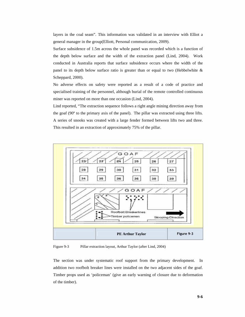
9-6
layers in the coal seam”. This information was validated in an interview with Elliot a
general manager in the group(Elliott, Personal communication, 2009).
Surface subsidence of 1.5m across the whole panel was recorded which is a function of
the depth below surface and the width of the extraction panel (Lind, 2004). Work
conducted in Australia reports that surface subsidence occurs where the width of the
panel to its depth below surface ratio is greater than or equal to two (Hebbelwhite &
Scheppard, 2000).
No adverse effects on safety were reported as a result of a code of practice and
specialised training of the personnel, although burial of the remote controlled continuous
miner was reported on more than one occasion (Lind, 2004).
Lind reported, “The extraction sequence follows a right angle mining direction away from
the goaf (90º to the primary axis of the panel). The pillar was extracted using three lifts.
A series of snooks was created with a large fender formed between lifts two and three.
This resulted in an extraction of approximately 75% of the pillar.
PE Arthur Taylor Figure 9-3
Figure 9-3 Pillar extraction layout, Arthur Taylor (after Lind, 2004)
The section was under systematic roof support from the primary development. In
addition two roofbolt breaker lines were installed on the two adjacent sides of the goaf.
Timber props used as ‘policeman’ (give an early warning of closure due to deformation
of the timber).

9-7
The report does not give an indication of cost differences between the primary and
secondary processes. This may be expected due to lower pick wear and reduced support
requirements” (Lind, 2004). Elliot is in concurs with this information (Elliott, Personal
communication, 2009).
Pillar Extraction at Boschmans Colliery
Dr Gavin Lind’s work on pillar extraction (Lind, 2004) reports, “The process uses a Joy
12HM31B continuous miner (with the dust scrubber removed) with three 10t shuttle cars.
The system produces an average of 47,310tpm derived from a three monthly average.
They operate on a two shift per day basis, with 15 personnel per shift.
The two year old panel consists of 10.5m square pillars, 3.8m high at a average depth
below surface of 60m. The bord widths 6.5m and the development safety factor 1.8.
Sizing of coal product varied, resulting in larger coal sizes than during development and
could be a consequence of pillar crushing during extraction. The picks therefore do not
break to their burden (pick spacing) as the coal breaks out of the face prematurely.
As this was an older panel at the time of secondary extraction, panel rehabilitation was
carried out before secondary extraction. This cumulative cost with the cost of secondary
extraction resulted in higher costs than during primary (development) mining. The mine
reported an increase of approximately 50% to the development cost. This information is
validated by Van Rooyen a production manager at Douglas (Van Rooyen, Personal
communication, 2008). Kenny the assistant general manager in his interview concurred
(Kenny, Personal communication, 2008). The Boschmans sequence is the same as that
used for Arthur Taylor.
It is important to realise that this may be a suitable method for the extraction of small
pillars. Small pillars are found in areas that were not originally planned for secondary
extraction. Engineers need to develop means of extracting this reserve.
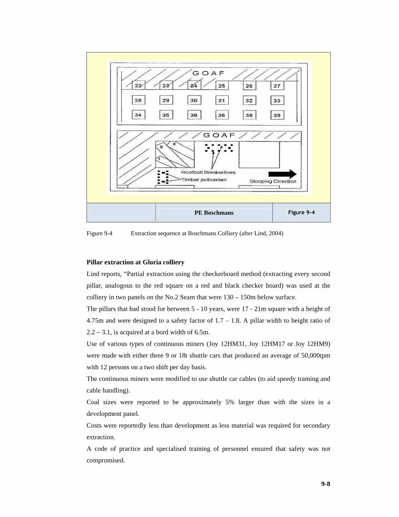
9-8
PE Boschmans Figure 9-4
Figure 9-4 Extraction sequence at Boschmans Colliery (after Lind, 2004)
Pillar extraction at Gloria colliery
Lind reports, “Partial extraction using the checkerboard method (extracting every second
pillar, analogous to the red square on a red and black checker board) was used at the
colliery in two panels on the No.2 Seam that were 130 – 150m below surface.
The pillars that had stood for between 5 - 10 years, were 17 - 21m square with a height of
4.75m and were designed to a safety factor of 1.7 – 1.8. A pillar width to height ratio of
2.2 – 3.1, is acquired at a bord width of 6.5m.
Use of various types of continuous miners (Joy 12HM31, Joy 12HM17 or Joy 12HM9)
were made with either three 9 or 18t shuttle cars that produced an average of 50,000tpm
with 12 persons on a two shift per day basis.
The continuous miners were modified to use shuttle car cables (to aid speedy traming and
cable handling).
Coal sizes were reported to be approximately 5% larger than with the sizes in a
development panel.
Costs were reportedly less than development as less material was required for secondary
extraction.
A code of practice and specialised training of personnel ensured that safety was not
compromised.

9-9
Geotechnical problems such as slips in the pillars causing weaknesses and pillar
fracturing at slips and dykes were encountered. No surface subsidence was noted which
is an indication of a value of below 2 for the width of the panel to the depth ratio.
The pillars were extracted on a 90º line on retreat” (Lind, 2004). This was substantiated in
separate interviews by Kenny (Kenny, Personal communication, 2008) and Van Rooyen
(Van Rooyen, Personal communication, 2008).
PE Gloria Figure 9-5
Figure 9-5 Pillar lifting sequence Gloria Colliery (after Lind, 2004)
Pillar extraction at Blinkpan colliery
Lind (2004) confirms that Blinkpan practiced a 2 Seam partial extraction operation of
checkerboard mining on 3.5 year old pillars using a Joy 12HM9 unmodified continuous
miner with three 10t shuttle cars.
They produced an average of 44,500tpm on a two shift per day basis with 14 personnel
per shift. The pillars were at centres of 12.2m and at a height of 4.2m. The bord widths
were 6.8m and the depth below surface was 80m (which equates to a pillar width to
height ratio of 2.9). The pillars were designed to an original safety factor of 1.8 in a panel
consisting of 7 roads.
Slips and stringers present in the pillars never really affected the operation. There were
no other geotechnical problems.

9-10
The pillars were extracted on retreat using a 90º extraction line in a similar fashion as
described for Boschmans colliery.
There was no surface subsidence noted.
A code of practice and specialised training ensured that no safety incidences were
reported.
The costs of the secondary operations were reported as being less than the development
costs (Lind, 2004). Information validated by concurring report (Kenny, Personal
communication, 2008).
Pillar extraction at Greenside colliery
Research, Lind (2004), verifies that Greenside colliery has a long history of pillar
extraction in the No.2, No.4 and No.5 Seams, using conventional, mechanised and
checkerboard methods to extract pillars. The most recent on the No.5 Seam is discussed
here.
Lind states, “The 13 year old pillars, 45m below surface, were extracted using a Joy
12CM6 continuous miner (modified to fit an automatic tram switch) and three 8t shuttle
cars.
The full extraction, single shift operation, using 18 personnel, produced an average
tonnage of 19,000tpm.
The bord widths were 7.5m and the original safety factor was 1.8. there is no report of
centres or pillar widths but it is back calculated by the researcher that the pillars were
approximately 8m wide hence 15-16m centres. No layout was reported.
The operation caused surface subsidence of approximately 1m (indicating that the panel
width to its depth below surface was greater than or equal to two).
The coal sizes produced were reportedly larger than a development panel attributed to the
aging of the pillars.
Specialised training and a code of practice was in place. There were no adverse safety
problems.
Lower overall costs of the operation were the result of lower pick consumption” (Lind,
2004).
Information validated by Bob Smith general manager retired,(Smith, Personal
communication, 2008).
Pillar extraction at New Clydesdale colliery
Lind stated “This full extraction, mechanised operation on the No.2 Seam extracted
pillars that were over 20 years old and approximately 60m below surface. The pillars
extracted were 8.5m square and had a height of 3.6m (pillar width to height ratio of 2.4)

9-11
designed to a safety factor of 1.8 with bord widths being 7.5m. No layout was reported by
the mine.
A Joy 12HM9 continuous miner (modified to fit an automatic tram reverse switch) with
three 8 ton shuttle cars produced an average of 38,000tpm on a two shift basis with 14
personnel per shift.
Spalling of the sidewalls during extraction, together with high densities of slips and bands
of sandstone and floating stone, were reported during extraction. Surface subsidence of
approximately 1.2m was noted (again a function of a large ratio, 2 or greater of panel
width to depth below surface).
Larger coal sizes than with development panels were reported. Costs were lower than for
development panels as a result of lower pick consumption. A code of practice and
specialised training resulted in no significant influence on overall safety being reported
(Lind, 2004).
9.1.2 Application of full pillar extraction after 2004
The pillar extraction processes discussed highlight developments prior to the research
conducted by Lind (2004). The research focuses on recent techniques in the Witbank and
Highveld fields. It must be remembered that significant rib-pillar extraction and its
derivatives was practiced prior to 2000. The specific application of developing and
extracting ribs has lost favour with the mines. The research by Beukes (1992) critically
discusses this method and was widely practiced in the Sasol group. Reasons for loss of
popularity included lower outputs during development phases. The tendency was to go
for smaller ribs (more pillar like) during development. We note remnants of the rib-pillar
process in the evolved Twistdraai system discussed previously.
The general concern that most mining companies have regarding pillar extraction relates
to the safety aspect of the mining technique (Lind, 2004). Of the cases presented here,
only two are still conducting pillar extraction.
The partial pillar extraction techniques are considered to be a lower safety risk than the
full pillar extraction method which owners stopped largely because of risk (Lind, 2004).
Lind (2004) reports, “In four cases the mechanised mining method was used. The choice
of mining equipment appeared to be company dependant and determined largely by the
height of the seam being mined (with general modifications to the continuous miner, by
either lowering it or removing the dust scrubber).
The physical dimensions varied but none of the safety factors were less than 1.8. This is
not surprising as these pillars are recent and were created using the pillar design formulae.
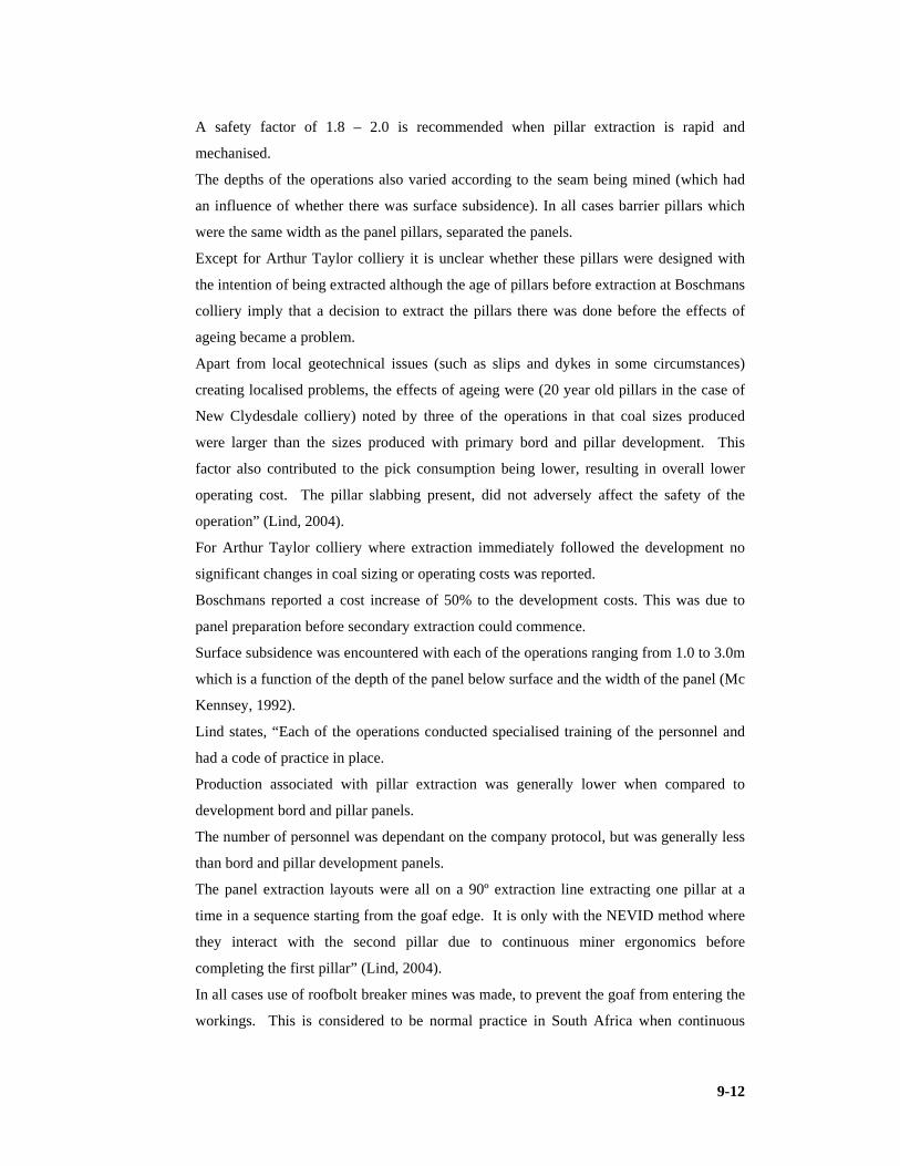
9-12
A safety factor of 1.8 – 2.0 is recommended when pillar extraction is rapid and
mechanised.
The depths of the operations also varied according to the seam being mined (which had
an influence of whether there was surface subsidence). In all cases barrier pillars which
were the same width as the panel pillars, separated the panels.
Except for Arthur Taylor colliery it is unclear whether these pillars were designed with
the intention of being extracted although the age of pillars before extraction at Boschmans
colliery imply that a decision to extract the pillars there was done before the effects of
ageing became a problem.
Apart from local geotechnical issues (such as slips and dykes in some circumstances)
creating localised problems, the effects of ageing were (20 year old pillars in the case of
New Clydesdale colliery) noted by three of the operations in that coal sizes produced
were larger than the sizes produced with primary bord and pillar development. This
factor also contributed to the pick consumption being lower, resulting in overall lower
operating cost. The pillar slabbing present, did not adversely affect the safety of the
operation” (Lind, 2004).
For Arthur Taylor colliery where extraction immediately followed the development no
significant changes in coal sizing or operating costs was reported.
Boschmans reported a cost increase of 50% to the development costs. This was due to
panel preparation before secondary extraction could commence.
Surface subsidence was encountered with each of the operations ranging from 1.0 to 3.0m
which is a function of the depth of the panel below surface and the width of the panel (Mc
Kennsey, 1992).
Lind states, “Each of the operations conducted specialised training of the personnel and
had a code of practice in place.
Production associated with pillar extraction was generally lower when compared to
development bord and pillar panels.
The number of personnel was dependant on the company protocol, but was generally less
than bord and pillar development panels.
The panel extraction layouts were all on a 90º extraction line extracting one pillar at a
time in a sequence starting from the goaf edge. It is only with the NEVID method where
they interact with the second pillar due to continuous miner ergonomics before
completing the first pillar” (Lind, 2004).
In all cases use of roofbolt breaker mines was made, to prevent the goaf from entering the
workings. This is considered to be normal practice in South Africa when continuous

9-13
miners are used (Galvin, 1993). He further noted that burial of the continuous miner in
South Africa was associated with taking the last one or two lifts of a fender. In terms of
controlled goafing snooks are deliberately left to act as a temporary support. A practice
(leaving of snooks) not favoured by the old miners who believed that it was bad practice
in that it would transfer stress to unsuitable localities. This practice differs from
operation to operation but generally leads to approximately 85 to 90% of the pillar being
extracted.
Burial of the continuous miners was reported at Arthur Taylor and Boschmans Collieries.
No indication as to the repercussions in terms of production losses and extent of
equipment damage was given (Lind, 2004).
9.1.3 Application of partial pillar extraction, after 200 4.
The partial pillar extraction techniques discussed by Lind (2004) were either
checkerboard, split and quartering (referred to as pocket and fender by Fauconier &
Kersten (1982)) or the NEVID method. Lind (2004) noted that, the NEVID method can
also be used as a full extraction method. “This mining technique intends to increase
extraction from the area without causing goafing from the area. The major consideration
with this technique being the overall safety factor is sufficient to prevent collapse while
engaged in pillar extraction” (Lind, 2004).
The factors of safety of these operations were either 1.7 or 1.8 when the development
phase was complete, with the pillars ranging in size from 12.2m to 21m (square pillars).
The split and quarter operations had 18m square pillars. The NEVID method however
requires a minimum size of 24m square. Generally a final safety factor of 1.2 was
considered adequate for these partial pillar extraction operations.
The age of pillars ranged from between one and seven years, with the operation that was
mining with the operation that was mining the seven year old pillars reporting an increase
in the size of coal cut as compared to those by primary bord and pillar developments.
All the operations showed very little in the way of structured planning (Lind, 2004) and
subsequent design procedures and methodologies. What was used extensively was the
now aged methodologies and the design considerations proposed by (Livingstone-
Blevins & Watson, 1982). It should not be ruled out that the pillar extraction designs
were conducted by experienced rock engineering professionals (Madden, 1989b)
and(Oldroyd & Van Rooyen, 1992). Lind (2004) identified the need for a standardised
approach similar to that used in New South Wales, Australia (Mc Kennsey, 1992).

9-14
Lind (2004) developed such a standardised approach for South African application to be
used by all current and future underground pillar extraction operations to limit the
possible impacts associated with this mining method.
One of the most experienced pillar extraction operators in South Africa who gained was
accountable for sections at Ermelo Mines, Usutu, Secunda Collieries and now (2010)
Khutala Colliery is Mr Neels Joubert a developer of the NEVID method. He reports
valuable experience with respect to the strategies when pillar extraction sections are in
proximity and challenges some of the accepted practices. He highlights the importance of
left hand and right hand scrubber positioned CM’s often referred to as left-hand and right-
hand machines and the impact they have on the sequence of pillar extraction an
orientation of the split. He reported that the machine by rule should keep the operator
against the solid. This has been mitigated by remote control units (Joubert, Personal
communication, 2010). His focus is shifting to the problem of extracting pillars on
multiple horizons or multiple seams.
9.1.4 New pillar extraction developments in South Africa.
SIMRAC Col613 method
Van der Merwe et al (2001) developed the method to ameliorate the propensity of
intersections to be the source of roof falls. Not surprisingly, it was found that the majority
of all roof falls occurred at intersections, which were responsible for 66% of the total.
Bearing in mind that intersections account for approximately 30% of the total exposed
roof, it means that one is more vulnerable to a roof fall injury in an intersection than in a
roadway (probability four times greater). According to Molinda et al (1998) in (van der
Merwe et al, 2001) the roof fall rate in the USA is eight to ten times greater in
intersections than in roadways. The amelioration is created through the principal that this
SIMRAC method has half the amount of intersections compared to NEVID for the same
linear distance.
Rectangular pillars are developed at 69.2 x 26.2m centres. Areal extraction on
development calculates to 38% (NEVID 47%).
Total extraction after secondary extraction is 74% (NEVID: 78%), hence comparing well
with that of NEVID, but offering fewer intersections and technically fewer potential roof
falls outside the caving area. The caving may be restricted by using ashfill after secondary
extraction.
Use is made of a double sided lifting cycle during extraction.

9-15
Staggered Intersections Col613 Method Figure 9-6
Figure 9-6 Extraction cycle (after van der Merwe, 2001)
Proposed Panel Layout Col613 Method Figure 9-7
Figure 9-7 Proposed high extraction panel layout (after van der Merwe, 2001)
The layout increases percentage extraction if the barrier pillar between the panels is
designed as a crush pillar. The linear layouts have been considered with mining systems
such as Magatar. The need to look at low safety factor small pillar partial extraction is
reiterated here. It should be noted that linear layouts are not a strategy by which pillar
extraction is directly applied but by which extraction is increased through the creation of
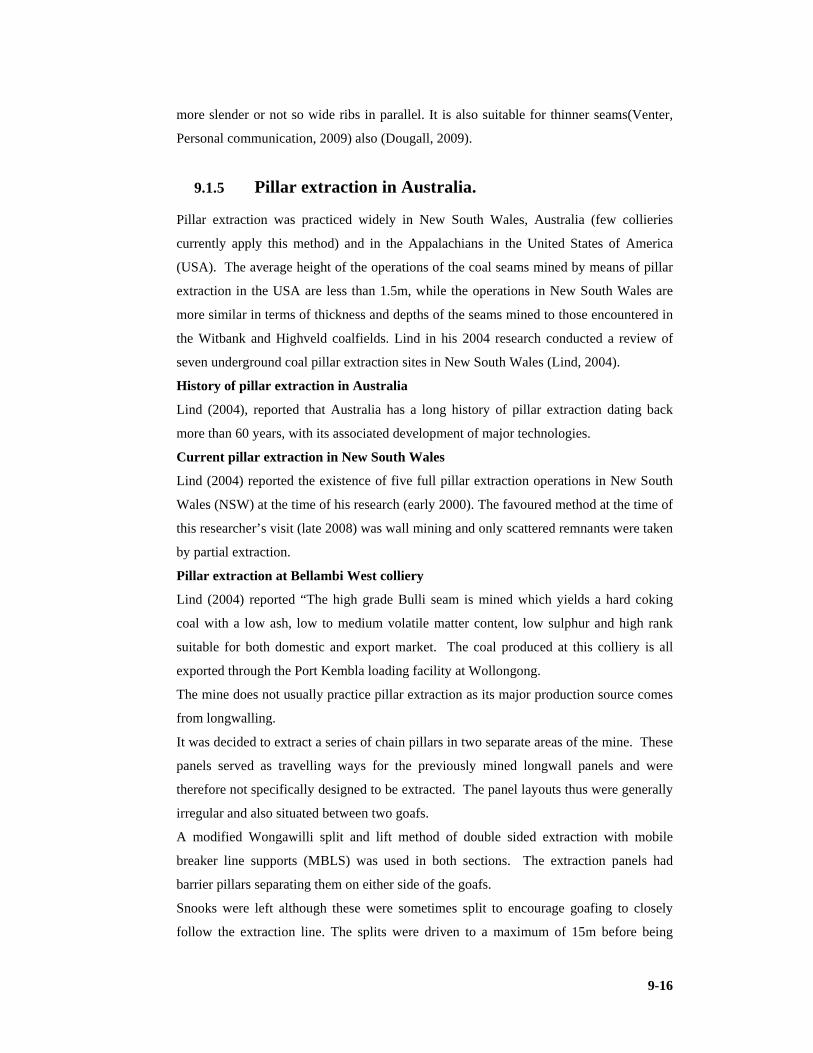
9-16
more slender or not so wide ribs in parallel. It is also suitable for thinner seams(Venter,
Personal communication, 2009) also (Dougall, 2009).
9.1.5 Pillar extraction in Australia.
Pillar extraction was practiced widely in New South Wales, Australia (few collieries
currently apply this method) and in the Appalachians in the United States of America
(USA). The average height of the operations of the coal seams mined by means of pillar
extraction in the USA are less than 1.5m, while the operations in New South Wales are
more similar in terms of thickness and depths of the seams mined to those encountered in
the Witbank and Highveld coalfields. Lind in his 2004 research conducted a review of
seven underground coal pillar extraction sites in New South Wales (Lind, 2004).
History of pillar extraction in Australia
Lind (2004), reported that Australia has a long history of pillar extraction dating back
more than 60 years, with its associated development of major technologies.
Current pillar extraction in New South Wales
Lind (2004) reported the existence of five full pillar extraction operations in New South
Wales (NSW) at the time of his research (early 2000). The favoured method at the time of
this researcher’s visit (late 2008) was wall mining and only scattered remnants were taken
by partial extraction.
Pillar extraction at Bellambi West colliery
Lind (2004) reported “The high grade Bulli seam is mined which yields a hard coking
coal with a low ash, low to medium volatile matter content, low sulphur and high rank
suitable for both domestic and export market. The coal produced at this colliery is all
exported through the Port Kembla loading facility at Wollongong.
The mine does not usually practice pillar extraction as its major production source comes
from longwalling.
It was decided to extract a series of chain pillars in two separate areas of the mine. These
panels served as travelling ways for the previously mined longwall panels and were
therefore not specifically designed to be extracted. The panel layouts thus were generally
irregular and also situated between two goafs.
A modified Wongawilli split and lift method of double sided extraction with mobile
breaker line supports (MBLS) was used in both sections. The extraction panels had
barrier pillars separating them on either side of the goafs.
Snooks were left although these were sometimes split to encourage goafing to closely
follow the extraction line. The splits were driven to a maximum of 15m before being

9-17
supported by a Fletcher roofbolter which places four 1.5m point anchored pre-tensioned
bolts with straps per row with rows spaced a distance of 1.2m apart. The bord widths in
all instances were an average of 5.5m. Once supported with roofbolts, the split was holed
and supported before lifting of the newly created 12m wide fenders took place. The
panels were operated with remote controlled continuous miners (a Joy 12CM11) and two
shuttle cars (Joy 15SC) each with an approximate 15t (metric) capacity.
Three Eimco mobile breaker line supports (MBLS) operated by remote control were
employed. Each of the MBLS units provided a maximum support resistance of 480t and
was positioned with the middle unit required to follow the centre line of the roadway.
These units were not set to their maximum resistance as this may have resulted in
premature failure of the roof. They were set to approximately one third of their
maximum load (160t). The MBLSs were moved forward a maximum of 2m each at any
one time and only one at a time. They were set to the roof after each move forward before
being moved again. They were spaced a maximum of 2m apart from each other and kept
as close to the continuous miner and solid fender as possible. In addition to the MBLSs,
timber breaker lines were also used as ancillary support.
The average production from these two extraction panels was approximately 60,000tpm,
whereas the longwall development panel produced approximately 35,000tpm.
There were eight personnel operating per shift, operating on a three shift per day basis,
five days per week. This was two persons less than the longwall development panels
where there were two dedicated roofbolt operators”.
Table 9-1 Complement per shift (after Lind, 2004)
Labour Complement Description Amount
Continuous miner operator 1
Cable handler 1
Shuttle car drivers 2
Artisans (utility personnel) 2
Section miner 1
Shift boss 1
Total 8
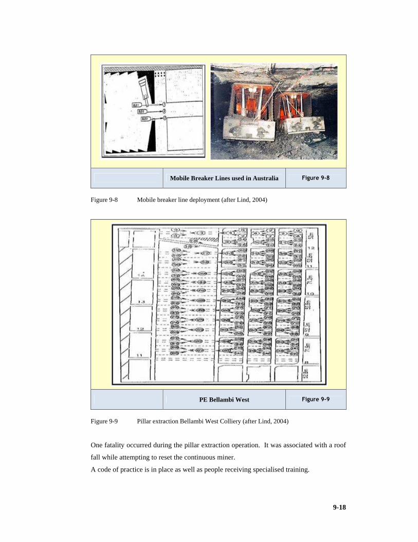
9-18
Mobile Breaker Lines used in Australia Figure 9-8
Figure 9-8 Mobile breaker line deployment (after Lind, 2004)
PE Bellambi West Figure 9-9
Figure 9-9 Pillar extraction Bellambi West Colliery (after Lind, 2004)
One fatality occurred during the pillar extraction operation. It was associated with a roof
fall while attempting to reset the continuous miner.
A code of practice is in place as well as people receiving specialised training.

9-19
No information pertaining to the costs of the operation could be made available due to
confidentiality of information (Lind, 2004).
This method (Figure 9.9) resembled the Rib Pillar Layout discussed in (Beukes, 1989a).
Pillar extraction at Charbon colliery
Lind reported, “Carbon colliery is situated in the Western coalfield. The Lithgow seam is
mined which has a medium to high volatile matter, medium to high ash and low sulphur.
All production from Charbon colliery is exported via rail to the Port Kembla loading
facility at Wollongong.
The Lithgow seam is generally 2.7m thick overlain by a dirt band, it is the only seam
mined and is situated 4.5m below the Lidsdale seam which has a thickness of 100mm.
The overlying strata consists of bands of claystone, mudstone and sandstone (which are
considered to be weak) and the floor consists of shales and tuff which are generally
considered strong. The depth of the Lithgow seam varies from 190m at the centre of the
mining lease to 30m at the extreme at the extreme inbye end of the panel and outcrops on
the perimeter of the mountain which overlays the deposit.
Two clay bands exist within the coal seam, which expand when wet, but does not affect
the mining operation.
A modified Wongawilli split and lift full pillar extraction method is used which is limited
to a 30m cover line (restricted area) to prevent damage to the mountainside. Beyond the
30m cover line only partial extraction without caving can be allowed (bord and pillar
mining not partial pillar extraction).
For full extraction panels, a panel is developed out some 650m with three headings at
40m centres with crosscuts driven at 50m centres to create three-way and four-way
intersections. The initial developments once complete leaves the secondary extraction
panel usually consisting of 14 splits. A barrier pillar of 40m width is left between the
extraction panels.
The 5.5m wide roadways are formed by either a Joy 12CM12 or a Joy 12CM11 (both
remote controlled). Two 15t capacity Joy 15SC shuttle cars are used to produce
approximately 14,000tpm during development.
The roadways are supported with four 2.1m full column resin supported roofbolts
installed per row with a strap, spaced 1.8m between the rows. The roofbolting is done
using the on board bolting system.

9-20
Table 9-2 History of rib-pillar and pillar extraction developments in Australia (Sheppard &
Chaturverdula, 1991)
History of Rib-pillar Pillar Extraction Development s in
Australia
Mining Method Changes
Date
Open End Lift, using diamond shaped pillars, DB. Pre 1942
Modified Old Ben System, DB, Bellbird Colliery, Cessnock. 1949
Coal cutters permitted in Open End Lifting, DB. 1954
Joy CM’s first introduced 1955
First Shuttle Cars introduced 1 1957
Precursor to the Wongawilli System developed at Nebo Collieries, Pocket &
Fender long pillars or ribs (unsatisfactory)
1957-1961
First successful Wongawilli System worked at Wongawilli and Nebo 1961
Continued improvement of the Wongawilli System especially with regard to
split centre dimensions.
Post 1961
Modified Wongawilli driving splits on the left and right side of panel
headings (roadways) simultaneously.
Late 1980’s
Partial Pillar Extraction, successful use of pillar stripping at Endeavour and
Cooranbong collieries.
Mid 1990’s
Full and Partial Pillar Extraction, successful use of pillar stripping at
Clarence, Munmorah and Cooranbong; and United for full and partial pillar
extraction.
Early 2000’s
Note 1: Scoops and tubs were around in 1955
The pillar extraction process begins with the pillar furthest inbye of the goaf side being
split and supported along its 25m centre to create pillars that are normally 20m wide.
These splits are supported with four 1.8m full column resin supported roofbolts, installed
per row with a strap and with the rows spaced 1.8m apart. The roofbolting operation is
again conducted using the on board bolting system.
Three remote controlled Voest Alpine mobile breaker line support units are used
(MBLSs) in this left and right lifting of the fenders. The first lift is always taken in the
solid fender before the goaf side fender is lifted. The MBLSs are advanced sequentially,
one at a time to a maximum of two metres at any one time before being set to the roof and

9-21
are spaced a maximum of 2m apart. The middle MBLS is required to follow the centre
line of the roadway. The MBLSs are set to the roof with a pressure of one third its
maximum loading capacity. The units are equipped with a gauge that moves a reading
from the green zone when they are set to the yellow zone as the supports start taking load,
indicating that the roof is settling. In addition to the MBLSs, timber breaker props
consisting of two rows of five props each are set in each of the headings, with only one
row being set in the heading furthest from the goaf. The roof bolting rigs are removed
from the continuous miner prior to lifting.
The maximum lift taken is approximately 9m into the previous goaf side and 10.5m into
the solid side. Only half the pillar is extracted per lift into the solid side. The lifts on the
goaf side will hole into the previous goaf. The angle of lifting is between 60º and 70º and
the lifts are cut the width of the continuous miner cutter head (3.6m).
Snooks are left as shown, with snooks closest to the solid edge of the panel being 10m
wide to ensure that the roadway remains open for return ventilation.
The lifting operation on a per shift basis produces more than the development operation,
as less roofbolting is required and this bottleneck is eliminated. The section is equipped
with eight personnel per extraction panel.
Thirteen panels to date have been extracted using this method of mining.
Surface subsidence was noted and rib spalling was also evident. The continuous miner
had been buried on two occasions with no loss of life or injury. The MBLSs were buried
on one occasion, attributed to the hanging of the goaf for a prolonged period of five
weeks, causing a violent goaf to over run them.
The operating costs were not indicated due to confidentiality. The product has to be
transported some 400km to the Wollongong export facility, this indicates that the
operating costs are low to ensure the profitability of the operation.
An interesting observation at this colliery was the use of a monorail system to suspend the
continuous miner’s power cable and water hose from the roof. This system reduces the
risk of the cable handler being trapped between the continuous miner and the ribside. It
also minimises the risk of the cables being damaged by ribspall. It also reduces the risk
of back injury to the personnel” (Lind, 2004).

9-22
Table 9-3 Labour complement per shift
Labour Complement Description Amount
Machine operators 5
Artisans 2
Section miner 1
Total 8
Figure 9.11 gives a locality map of the NSW coalfields.
Wongawilli RPE Charbon Figure 9-10
Figure 9-10 Panel layout Charbon colliery (modified Wongawilli split & lift) (after Lind,
2004)
9.1.6 Partial extraction using continuous miners in primary exploitation
This is the process of doing primary, secondary or tertiary development of main travelling
ways within the colliery. It is the creation of a bord and pillar layout to a required safety
factor in which the primary mining is not immediately or never followed by secondary
mining or caving techniques.
Development using a continuous haulage
Uys states, “Justification of the investment in a continuous haulage system:
1) The comparison between the continuous haulage system and the shuttle car operation
show that there is a definite point where the continuous haulage system is the better
choice.

9-23
2) To ensure that the continuous haulage operation reach high production volumes the
system would have to be placed in conditions which are favourable for a high
production rates.
3) Higher investment in a continuous haulage system can only be justified if we can
ensure that higher production volumes can be obtained. This can only be obtained
where there is a high availability from the continuous miner and the infrastructure.
4) The only factor that could be assured was an increase in production of at least 15%
mainly due to the fact that shuttle car change out time / wait on shuttle car time would
be eliminated” (Uys, Syferfontein presentation, 2006).
Sasol implemented the system at their Bossjesspruit colliery with a double pass CM unit
(Figure 9.15). The continuous haulage (Figure 9.13) did not deliver satisfactory
production and was accordingly transferred to Syferfontein underground.
Reasons for improving at Syferfontein:
1) “Better geological conditions.
2) High availability of infrastructure.
3) High availability of continuous miner and continuous haulage system.
4) Single pass continuous miner.
5) Minimum loss of production due to belt extensions.
6) Sixty degree angle splits” (Uys, Syferfontein presentation, 2006).
A continuous haulage system can be implemented successfully in South African coal
mines with an increase in production rates and a decrease in operating cost. This
however can only be done if factors like geological conditions, panel layout, cutting
sequence and the continuous miner in front of the haulage system are considered (Uys,
Syferfontein presentation, 2006).
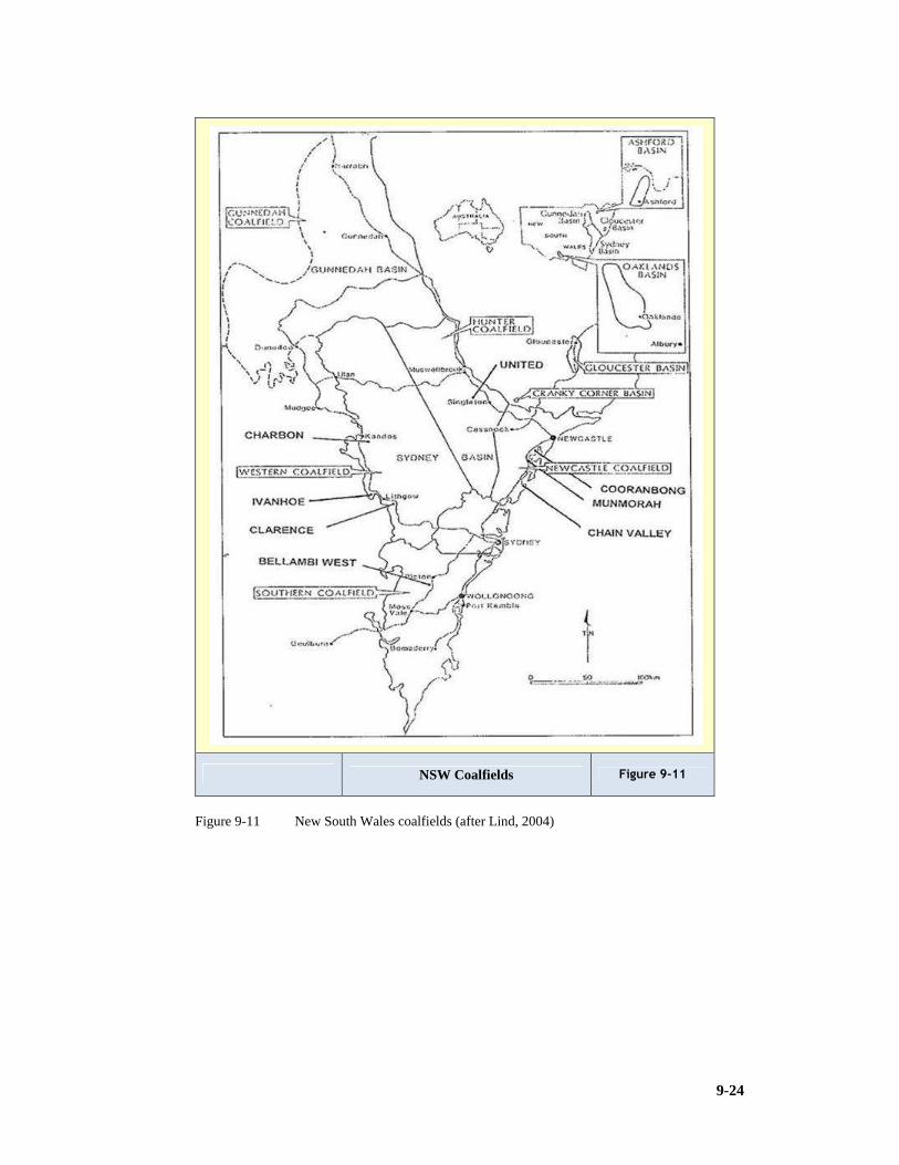
9-24
NSW Coalfields Figure 9-11
Figure 9-11 New South Wales coalfields (after Lind, 2004)

9-25
Long Airdox CH Figure 9-12
Figure 9-12 Long-Airdox Continuous Haulage (Uys, Syferfontein presentation, 2006)
ABM30 Figure 9-13
Figure 9-13 ABM 30 wide head continuous miner (Uys, Syferfontein presentation, 2006)

9-26
ABM30 with Head in Elevated Position Figure 9-14
Figure 9-14 ABM 30 Elevated head (Uys, Syferfontein presentation, 2006)
ABM30 Section Layout Figure 9-15
Figure 9-15 Section layout with diagonal pillars (Uys, Syferfontein presentation, 2006)

9-27
Table 9-4 Labour complement per day
Labour Complement Description Amount
Miners 3
ABM 30 operators 12
Continuous Haulage operators 10
LHD operators 2
Electomechanics 6
Helpers 8
Belt Team 7
Total Note: 3 X 8 hr shifts & 2 x 12 hr shifts 48
ABM30 Section Layout Figure 9-16
Figure 9-16 Peak production with ABM 30 & Continuous Haulage (Uys, Syferfontein
presentation, 2006)
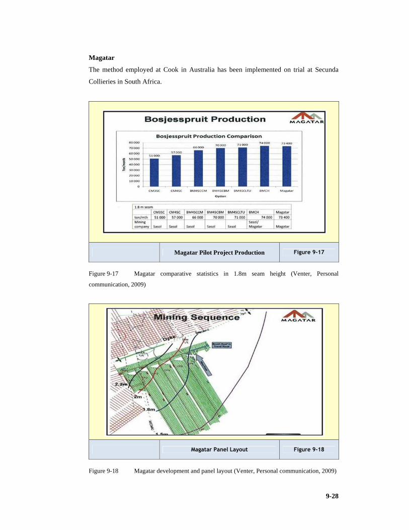
9-28
Magatar
The method employed at Cook in Australia has been implemented on trial at Secunda
Collieries in South Africa.
Magatar Pilot Project Production Figure 9-17
Figure 9-17 Magatar comparative statistics in 1.8m seam height (Venter, Personal
communication, 2009)
Magatar Panel Layout Figure 9-18
Figure 9-18 Magatar development and panel layout (Venter, Personal communication, 2009)

9-29
The unit is attractive in the lower profile of 1.8m were it exceeds 70,000tpm. This has
been done in competition with other equipment permutations such as CM and three batch
units (SC) or CM and four shuttle cars or Bolter Miner (BM), four shuttle cars and a CM
in a super section configuration. A BM continuous haulage was also compared. The
Magatar system delivered 73,400tpm as the best performer.
ELBM-75 Vibrant Roadheader
Coaltech investigated the feasibility of testing this product for South African
application.This unit is attractive for its roadheader properties which should be able to cut
more competent rock found in coal measures and most attractively because of its Chinese
origin is very competitively priced but will need modifications and specification upgrade.
It is however lower in mass than units traditionally employed in South African
conditions.
ELBM-75 Chinese Roadheader Figure 9-19
Figure 9-19 ELBM-75 Vibrant roadheader (after Coaltech)
South African conditions are characterised by:
1) Hard coal cutability, intrusions of hard geological disturbances are common place.
2) Production equipment damage, causing expensive, time consuming repairs.
3) Extraction by means of drill & blast techniques. 4) Expensive imported equipment innovated.
5) Low production volumes.
6) Damage to strata.

9-30
7) This results in reserves left, the lost reserve estimate is between 20 to 30
%.Characteristic features of the Chinese manufactured roadheader:
8) The unit is 2.2m high when fitted with a canopy.
9) It has a vibrating cutting head fitted with integral dust suppression.
Certain modifications were performed on the unit before test conducted in South African
conditions:
2) Flameproof main enclosure.
3) Lights replaced.
4) Trolex system (methane detector) installed
5) Canopy installed to protect the operator
6) Some coal mining sector expectations are:
7) To cut through dykes with UCS of 190 to 200 MPa.
8) To cut sandstone with a UCS of 90 to 100 MPa or shale with a UCS of around 40
MPa.
9) Not considered a production machine (4000 tons/month).
10) Compensate for lower production rates (cost)
11) To grow the local coal mining industry.
12) Speed up access through stone work developments.
13) Ensure free & fair competition between local suppliers
14) Some observations reported:
15) Cuts coal effortlessly using a “central reaming” process.
16) Vibrant action caused by eccentric mass action.
Challenges:
1) Loading spade is too far behind the cutting head results in a cut coal muck pile.
2) Unplanned movement – underweight & overpowered.
3) Fixed loading boom – 1/3 of shuttle car capacity filled

9-31
Rearview of ELBM-75 Figure 9-20
Figure 9-20 Rear view of Vibrant roadheader (after Coaltech)
Productivity improvement with effective roofbolting technologies.
ARO Twin boom roofbolter. Douglas Colliery deployed new technology twin boom
roofbolters to five U/G sections, they conducted an analysis of performance relative to
Brandspruit with the aim, to improve safety of their operators, save time and achieve
higher levels of productivity on these machines. The mine determined that some
interventions were necessary:
1) ARO Operators must be fully trained and competent in operating the machine, to
increase productivity.
2) W-Shape tungsten drill bits need to be looked at closely, as they seem not to be able
to cope with the stone in the roof strata
3) Engineering: ARO daily inspection check sheet to be implemented to ensure the
maintenance team and artisans are conducting the correct over inspections on the
critical items. Order and ensure that all critical spares are in place and available.
4) Mining: additional training on some of the roofbolter operators is still required. Shift
bosses & Miner to drive an awareness campaign on the operation of the machine, to
stop Operator neglect & damage to the machine.

9-32
ARO Rockbolter Figure 9-21
Figure 9-21 The ARO Twin boom bolter (Kenny, Douglas presentation, 2008)
Rockbolt Volumes Figure 9-22
Figure 9-22 Roofbolts installed per day using ARO (after Kenny, Douglas presentation,
2008)
The management considers the following approach applicable to the introduction of any
new system in the mining industry (Kenny, Personal communication, 2008).
The Fletcher bolting system. South African Coal Estates’ Greenside Colliery uses the
Fletcher bolting system and report on the cost of specific bolt resin combinations.

9-33
Table 9-5 and 9-6 identify the support cost elements which are major drivers of mining
costs these were current in 2009.
Table 9-5 Rock bolt costs (2009) (Franklin, Minova)
Bolt length Cost / bolt Resin type
0,9 m x 20 mm R17,45 Purple
1,5 m x 20 mm R31,76 Red / Yellow
Using 1.5m bolts with two capsules of resin. Red resin needs 30seconds to set and
Yellow resin 5-10min All cartridges are 23mm x 600mm (diameter x length) and are
applicable in all roof conditions including poor geological conditions. Figure 9-23
illustrates the buried CM mishap which is encountered sooner or later during pillar
extraction operations.
Table 9-6 Cost of resin (2009) (Franklin, Minova)
Resin Size Cost / case
Purple 23 mm x 600 mm R208,46
Red 23 mm x 600 mm R180,23
Yellow 23 mm x 600 mm R173,72
Figure 9-24 is an acceptable 16m cutting cycle which accommodates alternate cutting and
support of headings. Many standards do not allow the unsupported span to exceed 12m
in the interests of risk mitigation. Figure 9-25 displays the effective Fletcher Bolter
(Elliot, Fletcher Presentation , 2006).
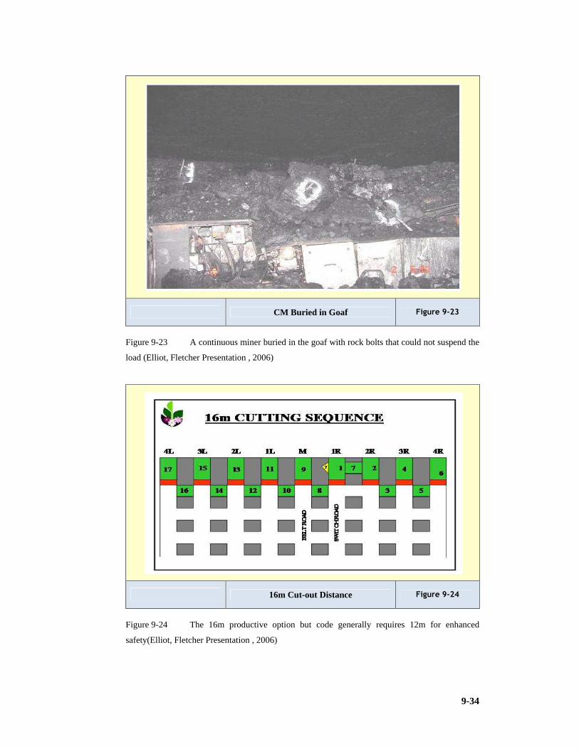
9-34
CM Buried in Goaf Figure 9-23
Figure 9-23 A continuous miner buried in the goaf with rock bolts that could not suspend the
load (Elliot, Fletcher Presentation , 2006)
16m Cut-out Distance Figure 9-24
Figure 9-24 The 16m productive option but code generally requires 12m for enhanced
safety(Elliot, Fletcher Presentation , 2006)

9-35
Fletcher Rockbolter Figure 9-25
Figure 9-25 Fletcher bolter (Elliot, Fletcher Presentation , 2006)
9.1.7 Mining methods in the United States of America
Black Beauty Coal Company – Air Quality #1 Mine
Black Beauty Colliery has a collection of smaller collieries of around 4Mtpa sizing. It
operates in thin seams of less 2m thickness and was considered a suitable case study to
benchmark for this profile. The Air Quality #1 Mine uses four continuous miner
production sections and operates them on two production shifts of 9.5 hours per day.
The target seam has a seam height of 1.5m to 1.7m and the mine delivers 4Mtpa from it.
A call of 1Mtpa per CM is considered acceptable in the company.
The operation favours more permanent fixed shaft infrastructure which is different to the
portable infrastructure favoured by the Australians at their Highwall operations (Hunter,
Personal communication, 2007). Figure 9-26 shows the shaft complex for Air Quality
Number 1 Mine.

9-36
Black Beauty Air Quality # 1 Mine USA Figure 9-26
Figure 9-26 Black Beauty Air Quality # 1 Mine (After Hunter, 2007)
Black Beauty Coal Company – Francisco Underground Mine
Francisco is one of the satellite shaft complexes operated by Black Beauty. It is relatively
new and is still capitalising. It does provide the company with a quality blending option.
The mine has one production section and operates two 9hour shifts per day. The seam
height has a slight advantage over Air Quality #1, and hence delivers the required call
(productivity) in slightly shorter time. The travelling distance to the section is also less
than at Air Quality #1. Seam height is 1.7m to 2.1m. The production from the one
continuous miner section is 1Mtpa (Hunter, Personal communication, 2007). Figure 9-
27shows the surface complex for Francisco Mine.

9-37
Black Beauty Francisco Mine Figure 9-27
Figure 9-27 Black Beauty Francisco Mine (after Hunter, 2007)
Five Star Mining – Prosperity Mine
Five Star Mining Company is an independent producer that may be classed as a small to
medium producer with five production sections also called at 1Mtpa per section
producing 5Mtpa cumulatively.The colliery uses four sections equipped with two
continuous miners each and one section with one continuous miner.
The production shifts of 9 hours per day on a two shifts per day cycle are preferred. The
mine has a labour complement of 325 employees.
The seam is 1.5m to 2.4m in seam height which may be considered as thin to medium in
profile. It should be noted that 1Mtpa per section is still considered an acceptable call
(Hunter, Personal communication, 2007). Figure 9-28 depicts surface complex at
Prosperity Mine.

9-38
Five Star Mining Prosperity Mine Figure 9-28
Figure 9-28 Prosperity Mine (after Hunter, 2007)
Triad Mining – Freelandville Mine
Triad Mining’s Freelandville Mine is a typical portal entry operation with adits from the
surface mining highwall. It is a small colliery producing 1Mtpa from one continuous
miner section.
The mine uses two production shifts of 9hours per day and employs 44 employees. The
seam height is thin and amounts to 1.4m to 1.7m thickness. Figure 9-29 depicts the portal
entrance to Freelandville Mine.
Triad Mining Freelandville Mine Figure 9-29
Figure 9-29 Freelandville Mine (after Hunter, 2007)

9-39
Speed Mine
Speed Colliery ranks as a large colliery producing 10Mtpa. It maintains to be the 3rd
highest producing longwall in the USA. It has two continuous miner sections and one
longwall. The CM sections are equipped with two CMs per section (14CM15).Two
production shifts per day for CM sections and three for the wall face are used in 1.5 to
1.8m seam height also classed as thin seam. Figure 9-30 is a photograph of the approach
to the adit of Speed Mine.
Mining Equipment common to the above mines
1) “Two Joy 14CM15 Continuous Miners per Section (in most cases).
2) Four DBT battery haulers per section.
3) Two Fletcher twin boom roofbolters per section.
4) One DBT Battery Scoop per section.
5) Stamler Feeder Breaker.
6) Non Flameproof Diesel Fork lift / Utility vehicle per section.
7) Stone dust applied by scoop (flinger attachment for bucket).
8) Getman Non Flameproof Underground Transportation System.
9) Getman Non Flameproof Road Builder/Grader.
10) Freelandville utilises a DBT Roofbolter (Twin Boom).
11) Prosperity and Speed Mines utilised 3 shuttle cars.
12) Speed Mine also utilises a DBT30M3 Continuous miner (Hunter, Personal
communication, 2007).
Figure 9-31 and 9-32 illustrate the underground forklifts and graders respectively.
Speed Mine Figure 9-30
Figure 9-30 Adit approach in hilly region for Speed Mine (after Hunter, 2007)
.

9-40
UG Forklift Figure 9-31
Figure 9-31 Forklift (photo by Hunter)
Best Practices on these USA mines:
1) “Battery Scoops dedicated for each section. Used for Sweeping so that the CM can
cut coal, also for stonedusting, cleaning, belt extensions, stocking roofbolters.
2) Two Joy Continuous Miners per Section. Only one cuts at a time while the other is
being trammed, and its area bolted, sweeped, stone dusted, and ventilation updated
Grader Figure 9-32
Figure 9-32 Grader (photo by Hunter)

9-41
Getman Scoop Figure 9-33
Figure 9-33 Getman Scoop for service use (photo by Hunter)
3) Four DBT Battery haulers per section.
4) Change out point is at the CM.
5) Two Fletcher twin boom Roofbolters per section one dedicated to each CM.
6) Feeder Breaker has surge capacity compatible to both discharge rate of haulers and
loading rate of conveyor. It is a self propelled machine.
7) 1050mm Section conveyor can handle the loading rate of feeder.
8) Non-flameproof diesel Forklift/ Utility vehicle per section. Assists with material
handling and sub assembly change outs.
9) Conveyor structures are suspended from roof. Easier installation, easier to clean,
doesn't sag into floor and doesn't misalign once set.
10) All consumables batched and palletised. Suppliers deliver mine specific packaged
goods.
11) Getman underground transportation system – Non flameproof. No LHDs on the mine,
no tractor on the mine. Everything is handled by the Getman tractor and trailer and in
the section by the Scoop.
12) Surface Material Handling is by rough terrain Forklift.
13) Scrubber System integrated into CM Design. Scrubber much more efficient than
South African units even at a lower volume. Work at a lower pressure 7 bar – no need
for on-board booster pump.
14) Tail end pulley fitted with screw thread scroll to discharge occasional runback coal.
15) “Rabbit trap” limit switch that stops conveyor when spillage occurs.
16) Electronic controls for sequencing and belt slip. Hydraulic belt take-up.
17) Coal centralising plates in chutes.
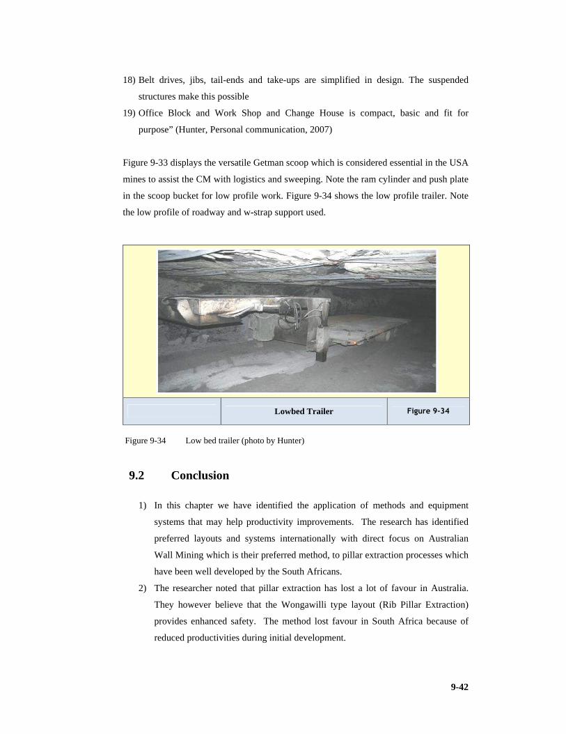
9-42
18) Belt drives, jibs, tail-ends and take-ups are simplified in design. The suspended
structures make this possible
19) Office Block and Work Shop and Change House is compact, basic and fit for
purpose” (Hunter, Personal communication, 2007)
Figure 9-33 displays the versatile Getman scoop which is considered essential in the USA
mines to assist the CM with logistics and sweeping. Note the ram cylinder and push plate
in the scoop bucket for low profile work. Figure 9-34 shows the low profile trailer. Note
the low profile of roadway and w-strap support used.
Lowbed Trailer Figure 9-34
Figure 9-34 Low bed trailer (photo by Hunter)
9.2 Conclusion
1) In this chapter we have identified the application of methods and equipment
systems that may help productivity improvements. The research has identified
preferred layouts and systems internationally with direct focus on Australian
Wall Mining which is their preferred method, to pillar extraction processes which
have been well developed by the South Africans.
2) The researcher noted that pillar extraction has lost a lot of favour in Australia.
They however believe that the Wongawilli type layout (Rib Pillar Extraction)
provides enhanced safety. The method lost favour in South Africa because of
reduced productivities during initial development.

9-43
3) The United States delivered some effective equipment modifications which are of
use in mine development. The focus here is however on lower seam profiles.
4) The modular Australian mines with highwall entries and the accent on portability
is finding favour with many mine developers.
5) The NEVID partial pillar extraction method is considered the safest way of
controlling the caving process and horizontal stresses associated with
underground mining and delivers an effective system of pillar extraction above
3.5m mining height.
6) Pillar extraction is favoured were flexibility is required and countries are
seriously constrained due to exchange rates and capital costs of imported mining
systems. The capital costs are far lower than those of wall faces.
7) Innovative systems are considered in this chapter such as the Linear Mining
System. Systems using Continuous Haulages to enhance safety and productivity
are researched. The Magatar system is one such system and uses tyred traction to
eliminate the wear on weak floors in its continuous haulage process.
8) Rock bolting equipment that eliminates production bottlenecks are considered
along with smaller roadheaders that are less capital intensive and could be of use
in section developments and the breaking of intrusives.
9) One of the greatest obstacles is the cost of CMs (ZAR30M). If cheaper and
smaller units become available such as some of the Chinese options it will
influence our deployment of CMs radically. Coaltech research organisation has
actively been pursuing this option.
10) The weight of certain larger CMs can also negatively impact on floor conditions.

10-1
10 INSTRUMENTS FOR MEASURING PERFORMANCE
10.1 Introduction
Most managers and companies identify critical control areas, or key performance areas
which enable them when measured to ensure that the performance is achieving objectives
(collaborated by research findings from data collected during 2006, 2007 and 2008). Due
to the abstract nature they are referred as soft issues or systems. Soft issues were defined
earlier in this dissertation and is also recorded in the index in the Appendices.
They may be expressed as standard operating procedures (SOPs) developed to achieve a
key performance standard or may take the form of guideline steps or keys to ensure the
objective is reached.
Data collection and interpretation for identifying the SOPs and the conceptualisation of
the idea they embrace was complemented through personal communication and reports of
line managers in the Sasol Mining team namely Jordaan, Scheepers, Steynberg, Leibrandt
and Streuders and mine managers, subordinate managers and engineers of collieries
benchmarked, namely Khutala, Matla, Douglas, Forzando, Gloria, Goodehoop, Bank,
Arnot, Phoenix, Brandspruit, Bossjesspruit, Middelbult, Twistdraai and Syferfontein
(Scheepers et al, 2000). This set of data and report Scheepers et al (2000) was made
available to this researcher by a General Manager of Sasol Mining, Secunda Collieries,
Mr Pierre Jordaan, and was complemented by interview and personal communication.
A Mine in Botswana was used as a case study by this researcher for many of the concepts
discussed in this research. But this is still a growing or learning organisation and some of
the concepts are not perfected in application by them at the time of this research. They
were however used as a target subject, by this researcher, to implement ideas and over
time monitor results.
The Scheepers, Steynberg, Leibrandt and Streuders Report
A system identified by a world class achiever, in the sample population, Sasol Mining,
controls Quality, Cost, Delivery, Safety and Morale as measuring instruments for
performance (Scheepers et al, 2000). These aspects were used as guidelines to evaluate the
performance of the identified mines.

10-2
Treated as part of continuous improvement cultures at Sasol and Khutala (BHP Billiton)
it was noted that these operators had formalised the process and had implemented it
culturally into the organisational behaviour.
The mines studied were selected because of their acknowledged achievements and status
in the coal industry in South Africa. These mines were considered by their peers as being
top performers.
Mines focus on getting things done right and on doing the right things. Most have
accepted a culture of ensuring that it gets done right the first time (Quality Management).
This requires that objectives are clearly set by both, the supplier and the user, of the
service or product developed. They need to establish by consensus what needs to be done
by whom and by when. It may involve a complicated and sophisticated formal planning
process in certain instances such as the 7 steps of planning and annual planning cycles for
the development of budgets and 12 month plans including medium term or 5 year plans
often for the life of mine. Planning becomes an independent chapter in its own right and
that is not the objective here (refer to Chapter 13). Mines need to ensure they meet market
demand at the correct product specification which normally includes not only volumes or
masses to be delivered but also includes limiting or quality criteria. In coal the proximates
and the ultimate elements or constituents of the coal rock (which is a fuel mineral, made
up of lithotypes for example vitrain and macerals for example vitrainite) is placed under
the spot light. This often requires declaring a reserve from a resource. This may not be
achieved without laying a detailed capital and operating plan to that resource and
determining or budgeting what the potential income statement and balance sheet for a
business cycle implies.
Volumes are often seen as the prime deliverable to customers and quality will involve the
type of coal, the rank of coal and often its grade or purity (Ash Content) or potential
chemical energy value (Calorific Value). Its application or use is critical and the dilution
(such as moisture content) or problematic qualities (abrasiveness) need to be controlled.
Another such a problem creator is fine coal for example.
Out of the key performance indicators that some mines focus on, the following are
considered important (and an attempt has been made to quantify the impact):
10.2 Reduction of Fine Coal Volumes
“One such threat to specification qualities other than the inherent proximate (CV, Ash,
Moisture, Total Sulphur and Fixed Carbon) and ultimate characteristics (Elemental

10-3
Chemical composition H, N, O, C, S and P etc.) is fine coal or coal outside the
specification size grading. Fines are generated in the cutting and transportation process
and often the amount of fines because of the contamination threat is strictly controlled,
even if the final user grinds the delivery to fine grading for injection into boilers”
Scheepers et al (2000). It is in fines were greater moisture dilution has potential to reside
including impurities that contribute to abrasiveness and increases beneficiation costs
when effort is made to bring the fines to specification.
Sasol Mining which supplies coal for conversion (to produce hydrocarbons from the
macerals) is in a unique situation in that fine coal is a major enemy, whilst other captive
collieries do not appear to have this problem. To the export collieries, this is however also
a threat. It is therefore essential to control fines (seen as a critical performance area or
indicator) for certain operations to be a success. Some mines controlled it indirectly by
evaluating pick spacing’s, this was done by Gloria (Scheepers et al, 2000). It is
understood that one of the factors that contribute to fine coal is related to cutter pick
efficiencies. Blunt picks or inefficient picks will require more grinding of the cutter head
on the face to remove a required amount of coal and in the process would generate more
fines. Eskom generally is adverse to fines owing to higher than expected contamination
levels (of abrasive constituents and moisture) and are also more expensive to beneficiate
to a suitable quality.
At Bank Colliery, an export mine, pick consumption (a cost driver) was a greater concern
than the amount of fines created by the various options they looked at to increase pick
life. It is this researcher’s opinion that owing to the relative hardness of the coal, Bank is
not prone to generating as many fines.
“Phoenix Colliery also focused on the fine fraction. According to the mine manager, the
Duiker group has done a lot of work to ensure the sizing of their product for the various
markets. It was found that conventional (blasting) methods resulted in higher fines
percentages but delivered a better spread over the various product sizes (Scheepers et al,
2000)”. In the experience of this researcher the more mechanised the process the more
likely the propensity to generate fines. When doing blasting the calculation of a suitable
powder factor input to create a suitable muckpile is essential and may require some
modelling and blast design to enable this.
“Sweeping is an important activity in the control of fines as coal lying on the roadways is
prone to trampling and accordingly crushed fine and received in this state when
eventually swept and delivered. A number of sections had dedicated LHDs Scheepers et
al (2000) The LHDs should be deployed in the cleaning of loose coal in roadways thus

10-4
preventing the trampling potential when the coal is left to lie around as batch haulage
units and the LHD itself will have an impact on fines generation).
The measures implemented to reduce fines included investigations into: pick spacing and
lacing; drum design; cutting operations; chute and bunker design; conveyor design
(speeds and transfer mechanisms); rehandling or double handling of coal; trampling on
coal; and section housekeeping. Often these investigations provide some solution but
generally the problem perpetuates and coal will or did produce fines. The need to reduce
the formation of fines is essential and may be seen as a size specification and therefore
impacts on quality of the product if outside the tolerance level. Many users will accept a
fines concentration of up to 15% by mass but will penalise the supplier if this level is
exceeded. The astute producer, however, will blend in fines which normally stockpiles
when screened out to ensure the level of dispatch to the customer is at 15%. The fines
stockpiles in total, in South Africa alone, are many millions of tonnes in mass.
Table 10-1 Mines with fine coal as threat and actions to counteract it (from Scheepers et al
2000)
Mine
Fine coal a threat
Deal with problem LHD per section
Sasol
Yes
Pick spacing / lacing / drum design / cutting operations / sweeping / chute design / bunker design
0.5 LHD per section
Khutala
No
0.33 LHD per section. Battery haulers can sweep at tip area
Goedehoop
Yes
None observed
LHD per section
Forzando
Yes
None observed
Douglas
Yes
None observed
LHD per section
Phoenix
Yes
Conventional mining
Conventional - loader:
Matla
No
Scoop per section
Bank
Yes
None observed
LHD per section
Arnot
No
LHD per section
Gloria
Yes
Start - look at pick spacing

10-5
10.3 Coal Quality
The quality is pre-empted through prospect drilling of cored boreholes and sampling the
core for laboratory analysis. A preferred horizon is determined if the whole seam is not
taken this is referred to as a selective horizon.
The controls apart from effective sampling of boreholes are orientated around the horizon
control techniques applied by the operator. This was addressed by most of the collieries
investigated.
Goedehoop Mines selectively mine up to 4.5m high, leaving the poorer quality roof and
floor coal. This is a similar approach at Marupule Colliery in Botswana (Anglo). Floor
strata may be to weak to carry the heavy CM and the coal strength provides better
resistance. Marupule (MCL) leaves 1m of coal in the floor to even out undulations and
hence avoid contamination from low strength floor lithotypes (rock layers). The CM will
cut a 4.2m channel to attain a selective quality extraction that is optimum for the 8m seam
height. The 2 to 3m poorer quality coal is left as roof, isolating the mudstones found
outside the coal channel in the roof, which displays poor strength and quick weathering
characteristics. At Sigma Colliery in the Number 3 seam this was essential as the roof
strata was composed of carbonaceous shale and needed to be sealed by a layer of at least
0.5m of coal to enable support integrity to be maintained. Only resin grouting could be
used on the rebar rockbolt as an expanding or mechanical shell would allow weathering
of the shale, the quick deterioration of roof conditions and the consequent roof falls that
resulted.
Drilling by means of hand drills into the roof until the shale or sandstone is exposed and
similarly, into the floor helps the operator determine at what horizon he is instantaneously
positioned in the coal seam. The operator can determine how far he is from the coal roof
limit by measuring the depth of the drill hole. He should be able to determine the limit by
the change of duff or drillings colour when the rock changes from coal to other sediment
or type of rock.
“At Douglas a plan in section was used profiling the coal seam. This gives a clear picture
of the thickness of coal that is to be left in the roof for quality control. The thickness of
the roof coal is controlled by drilling holes in the intersections to allow the measuring of
and determining horizon position. Gloria controlled contamination by examination of the
floor cut. The section ganger measured the floor cut of the previous shift and recorded it.
Quality may be controlled during data modelling in the scheduling phase allowing the
determination of the optimum selective horizon within thicker seams.” (Scheepers et al,
2000).

10-6
On some mines use of the electronic assistance equipment such as the Joy’s JNA (Joy
Network Analyser) were not applied to control horizon.
“In general, the mines who were mining selectively managed to control the Quality by
staying within the range by either following markers, by drilling and determining roof
coal thickness or by reduced cutting distances to allow better control by the operator”
Scheepers et al (2000).
Quality influences the price attained for the delivery. Generally a broad spectrum of
proximate parameters are controlled, generally on an air-dry (ad uc) (air-dry
uncontaminated) basis as opposed to as received. Penalties may be incorporated if
specifications are not met to specific tolerances having cost implications for the supplier.
The supplier’s reputation is also at stake.
Middelburg Mines use a system on their Surface Mining Operation known as CAVITY
focused around product specification on qualities and the relative acceptance or rejection
by the customer (Calorific value; Ash; Volatile matter; Index of abrasivity; Total
moisture; and Yield). They also use the A to G Principle to ensure they mine the correct
quality and do not contaminate it afterwards (Area; Barrels; Contaminating triangles;
Distance; Edge; Flow; and Geological factors). Both ‘CAVITY’ and the ‘A to G’ are “aid
to memory” acronyms to help reduce abrasiveness and contamination, hence control
quality.
Table 10-2 Quality control at mines (from Scheepers et al 2000)
Mine Export/ Eskom
Quality Control
How
Sasol Sasol Yes Measurement /Cutting control/roof coal. Douglas Export Yes Selective mining, specific section plans, drill,
intersection Forzando Export Yes Hard floor and roof Bank Export Yes Selective mining Goedehoop Export Yes Selective mining Phoenix Export Yes Drill and blast operations Gloria Export Yes Miner measure contamination Arnot Escom Poor Poor machine utilisation for floor control e.g.
JNA light Khutala Escom Yes Selective mining Matla Escom Yes Selective mining
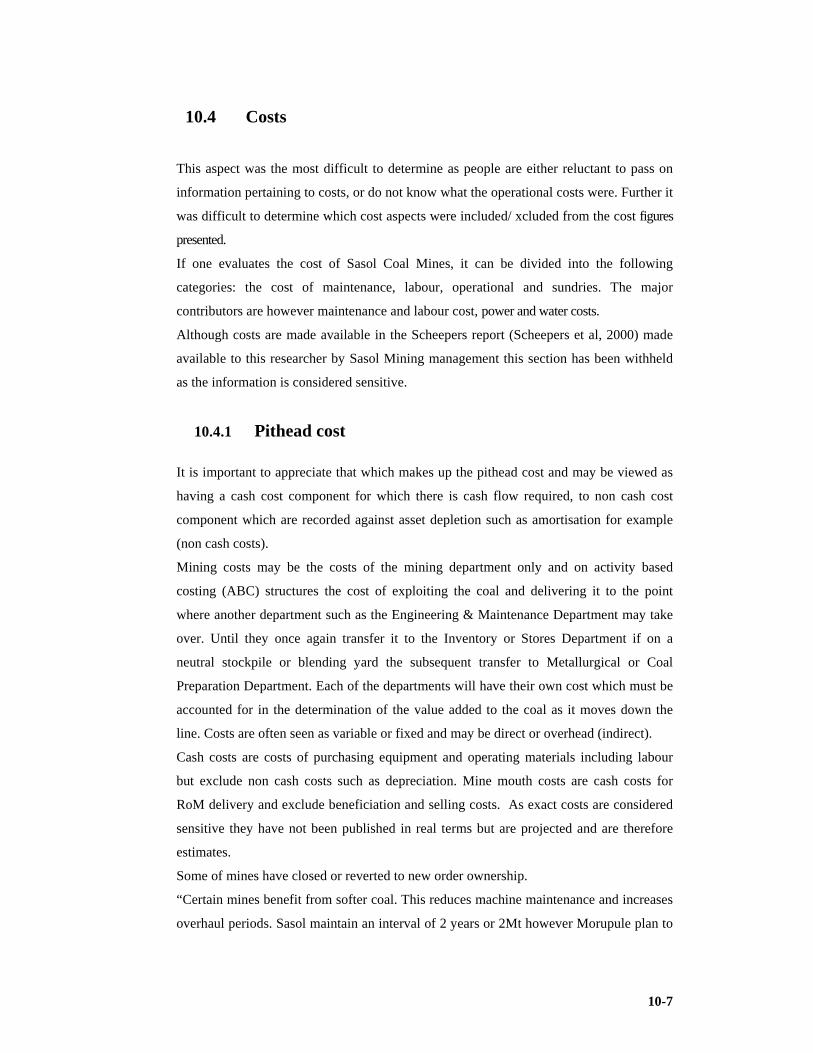
10-7
10.4 Costs
This aspect was the most difficult to determine as people are either reluctant to pass on
information pertaining to costs, or do not know what the operational costs were. Further it
was difficult to determine which cost aspects were included/ xcluded from the cost figures
presented.
If one evaluates the cost of Sasol Coal Mines, it can be divided into the following
categories: the cost of maintenance, labour, operational and sundries. The major
contributors are however maintenance and labour cost, power and water costs.
Although costs are made available in the Scheepers report (Scheepers et al, 2000) made
available to this researcher by Sasol Mining management this section has been withheld
as the information is considered sensitive.
10.4.1 Pithead cost
It is important to appreciate that which makes up the pithead cost and may be viewed as
having a cash cost component for which there is cash flow required, to non cash cost
component which are recorded against asset depletion such as amortisation for example
(non cash costs).
Mining costs may be the costs of the mining department only and on activity based
costing (ABC) structures the cost of exploiting the coal and delivering it to the point
where another department such as the Engineering & Maintenance Department may take
over. Until they once again transfer it to the Inventory or Stores Department if on a
neutral stockpile or blending yard the subsequent transfer to Metallurgical or Coal
Preparation Department. Each of the departments will have their own cost which must be
accounted for in the determination of the value added to the coal as it moves down the
line. Costs are often seen as variable or fixed and may be direct or overhead (indirect).
Cash costs are costs of purchasing equipment and operating materials including labour
but exclude non cash costs such as depreciation. Mine mouth costs are cash costs for
RoM delivery and exclude beneficiation and selling costs. As exact costs are considered
sensitive they have not been published in real terms but are projected and are therefore
estimates.
Some of mines have closed or reverted to new order ownership.
“Certain mines benefit from softer coal. This reduces machine maintenance and increases
overhaul periods. Sasol maintain an interval of 2 years or 2Mt however Morupule plan to

10-8
stretch this to 4 years or 4Mt. The differences lie in the relative hardness of the seams”
Scheepers et al (2000).
In the Morupule case study it is evident that the softer coal or the absence of abrasive
lenses (sandstone lenses), greatly enhances the pick life and overhaul intervals of
equipment. This reduces mining consumable costs and hence benefits the production of
cheaper coal. Often the maintenance costs are also reduced as there is less fatigue on the
CM or coal winning machine.
Pithead Cash Costs Projected Figure 10-1
Figure 10-1 Projected pithead cash costs for 2010 from 2004 data
10.4.2 Maintenance cost
Maintenance costs are a major contributor to mining costs. Costs will by their very
nature be the target and focus of managerial control. Table 10.4 depicts some cost drivers
such as time, interval and agent.
“The Rand per tonne values were rarely mentioned during visits. Factors influencing the
maintenance cost had to be identified and compared to allow comparisons.
Pick consumption is a means of gauging coal hardness in practice. Consumptions of
90t/pick (relatively soft coal) were mentioned. Arnot reported 19t/pick (relatively hard coal),
Bank 24t/pick and Gloria 35 to 45t/pick. Sasol coal was also in this range. The 30mm shank
picks were commonly used. In the case of those mines, mining softer coal, the machine
overhaul intervals were up to 3Mt, for example, Khutala.

10-9
Table 10-3 Maintenance cost drivers
Mine Machine Maintenance time Interval Overhaul (t) By:
Brandspruit
HM31 Night /Day shift 2 Weekly 1.75Mt Joy
Middelbult
HM31 Night shift 2 Weekly 1.5Mt Joy
Khutala
4 Seam:
ABM30 x 4
HM17 x 6
2 Seam:
ABM30 x 2
HM17 x 6
Day shift Monthly CM ‘s – 2.5-
3.0Mt
Own overhaul
Matla
HM9 Night shift Monthly 1.1-1.2Mt Matla
Goedehoop
2 seam
HM21
HM31
2 Hours Daily 1.8Mt (HM 21 &
HM 31)
Anglo Coal Central
Workshop
Phoenix
Conventional In shift Every 10th
day
Used Duiker central
workshop- now Joy for
s/ cars
Bosjesspruit
HM31
HM9
Night Shift 2 Weekly 1.5Mt
1.2Mt
Joy
Twistdraai
HM31
Night/Day shift
2 Weekly
2.0Mt else earlier
if machine was in
Joy
Twisdraai
Export
ABM30
ABM12
HM31
Night shift 2 Weekly ABM 4Mt (mini -
2Mt)
HM31 -2Mt
(mini-0.8-1 Mt)
Mini self Major by
OEM
Arnot
HM31 x 5 Day shift 2 Weekly 2 Mt/3 years
Joy/ Anglo Coal
central
Bank 2
seam
Voest AM80 x
5
Voest ABM80
In shift ABM30: mini-
2.2Mt
Major -3Mt
OEM ( Voest
maintenance contract)
Forzando
HM31 x 2 1 hour per day Daily Joy
Syferfontein
u/g
HM21
ABM20
ABM30
Sundays 2 Weekly 2Mt
4Mt
4Mt
OEM
Gloria
HM17
HM31
Night shift 2Mt Full Joy maintenance
Douglas
ABM30 x 1
HM31 x 8
14CM15 x 1
Saturday & Sundays Monthly 1.3-1.5Mt OEM
10-10
The maintenance on the section equipment was also only done once a month in mines
with softer coal compared to bi-monthly maintenance on those with relatively hard coal.
It was evident that the softer coal contributed positively to the cost of maintenance,
especially in the case of continuous miners.
Certain operators use the OEM (original equipment manufacturer) to do maintenance.
Matla do machine overhauls at the central workshops on the mine. It has been perfected
to the stage that some of the other mines actually consider a machine overhaul with Matla
instead of the OEM” (Scheepers et al, 2000).
10.4.3 Labour cost
Owing to the difficulty of obtaining cost information Spalding’s study (SA Coal Report)
was used as a moderator and baseline assessment.
Many mines opt for different organisational structures the trend is to become flatter and
leaner. The drive is to ensure maximum output for minimum input. Khutala and Matla are
most probably the leaders regarding labour productivity. Both mines produce some
14Mtpa. Khutala employ 1,441 employees, and Matla 1,640.
“At Khutala a mine manager, for each seam, manages the two seams. The typical structure
for a seam will be a mine manager with two mine overseers and an engineer reporting to
him. Some 700,000t is produced from a seam. This means that a mine overseer is
responsible for producing some 350,000tpm. The mine overseer is also responsible for
infrastructure in his area of responsibility which includes road building, conveyors, water
pumping. Six shift overseers, two of which are responsible for the outbye area, are
allocated. A shift overseer is responsible for three production sections on his shift. On the
engineering side, five foremen manage the seam, four being responsible for the
production sections and work shifts. There are also a further three chief foremen. To be
able to look after such a wide area with such a small team, delegation down to miner and
artisan level is vital.
At Matla the system is more or less similar. The mine is divided into three mines,
operated individually by a mine manager each. A general manager overlooks the
operations. A mine manager, production manager and engineer manage each mine.
Section superintendents look after two sections each, with two foremen and shift
overseers. The Engineer has a superintendent reporting to him, together with five
foremen, and they look after all the services and the boiler shop, transport, mechanical
and electrical departments. Inbye the section the crew consist of the miner, electrician,

10-11
fitter, aid, two CM operators, three shuttle car operators, two roofbolt operators, four
multi skilled operators and 0.5 scoop drivers” (Scheepers et al, 2000).
The Scheepers team reported that “Most collieries have in-section structures of more or
less similar composition. The mines, not only had lean in section structures, but also lean
management structures. Use of a small number of people on the services and
infrastructure was notable on the better performers. None of the mines had a manager
with an engineer looking after the services. In almost all cases the manager responsible
for the production in an area, would be responsible for the services of that area. This was
achieved by delegating this duty to the mine overseer responsible for the production in
that area, or to another mine overseer reporting to the responsible manager.
Geographic area would be a major variable in this comparison. The mines that mined
multiple seams had an even greater advantage in this instance. Some mines were
geographically extensive (Scheepers et al, 2000).
Labour Complement Figure 10-2
Figure 10-2 Labour complement per shift
Many mines made use of contractors for the building of walls and moving of stonedust
barriers. In some cases contractors were also used to do belt extensions.
A major opportunity exists for certain operators to reduce cost dramatically if they re-
structure and increase productivity levels to levels observed at Matla, Khutala and
Syferfontein (underground). The need is to reduce large number of service labour to
essentials and increase multi-skilling productivities.

10-12
Shifts per Week Figure 10-3
Figure 10-3 Shifts per week
Table 10-4 Section labour on a shift basis (From Scheepers et al (2000)
Mine
Wage Operators
Miner
Fitter
Electrician EM
Sasol
14 (Incl. Maintenance operator)
1
2
Douglas
10 (incl. leave relief)
1
1
1
Forzando
13 (Haulage)
1
0.66
0.66
Bank
8
1
1
1
Goedehoop
9 (incl. leave relief)
Faceboss
1
1
Phoenix
25
1
Gloria
9
1
1
1
Arnot
9 (incl. leave relief)
1
1
1
Khutala
12
1
1
1
Matla
12.5
1
1
1
“A pool bonus system as used by all the mines visited encourage section workers to get
along with the bare minimum and rather share in the bonus of someone that is not
necessary in the section” (Scheepers et al, 2000).

10-13
Scheepers et al (2000) states, “Multi skilling becomes essential as section labour numbers
are reduced as the people could perform any function trained for in the absence of a
colleague. Without such a system it becomes necessary to build in excess to cater for
unforeseen circumstances” (Scheepers et al, 2000).
10.4.4 Operational cost
Operational costs will be the major determinant of the profitability of the mine in the long
run. Table 10-5 lists pick & bolt efficiencies.
Table 10-5 Pick and roofbolt efficiencies (from Scheepers et al, 2000)
Mine
Seam mined
Tonnes / pick
Bolts/m2 (normal roof)
Bolt length (m)
Sasol
4
35
0.19
1.0/1.2
Khutala
2 & 4
80
0.14
1.5
Matla
2 &4
80
0.214
1.2
Douglas
2 & 4
90
0.214
Forzando
4 Lower
75
Spot
Gloria
2
35-45
1.6/2.0
Goedehoop
2 & 4 seams
60-90
0.014
1.5
Bank
2 & 5
24
0.143
1.5
Arnot
2 &2A
1 9 - 100
0.214
0.9
Phoenix
1
NA
Spot
“Picks and roof support make up the major portion of operational cost. Although
operational cost contributes to the total cost to a lesser extent, it must not be overlooked.
Douglas, Khutala, Matla, Goedehoop, and Forzando are all mines that get some 90t per
pick on a 30mm shank pick. Arnot gets around 20 while Bank and Gloria get 24 and 45t
per pick respectively. The higher tonnes per pick for the collieries that are in the 90 range
and result in much lower expenditure on this item and increased production time. It was
also evident that these collieries had to do less maintenance on their continuous miners
and was able to get a higher tonnage from machines before overhauls. Sasol Coal on
average achieved much less tonnage per pick. Bossjesspruit, Twistdraai and the export
mines all exceed R1/t on pick costs” Scheepers et al (2000).
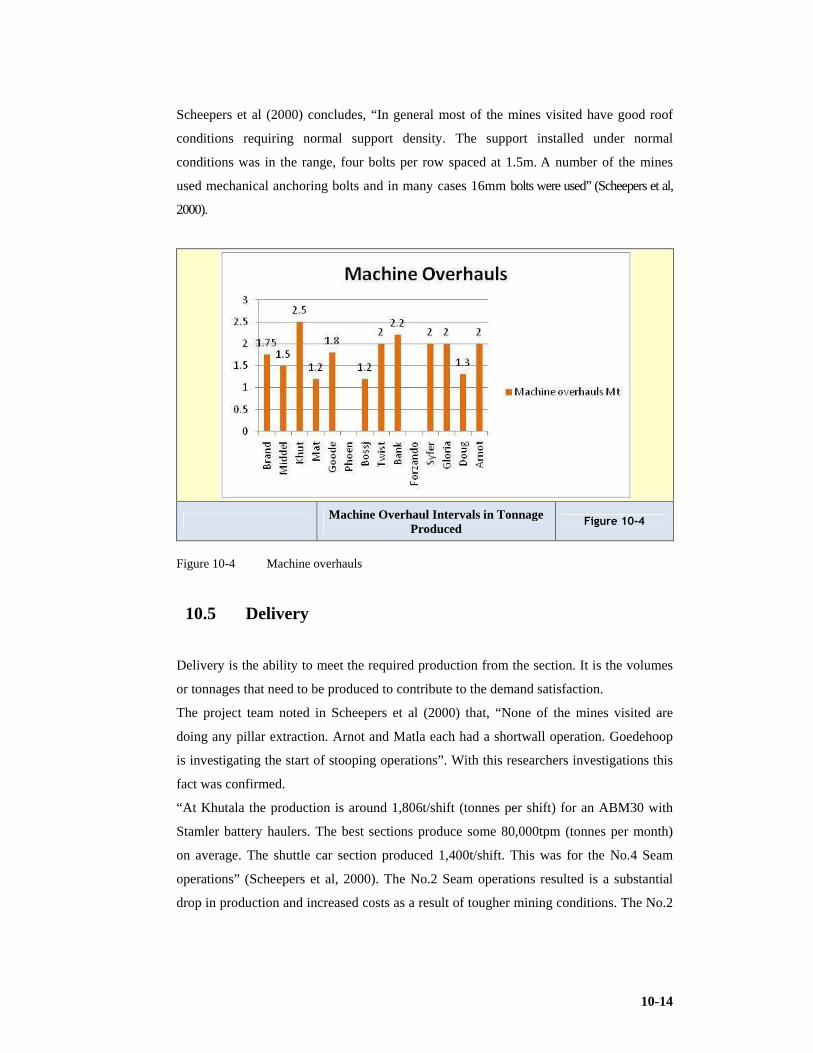
10-14
Scheepers et al (2000) concludes, “In general most of the mines visited have good roof
conditions requiring normal support density. The support installed under normal
conditions was in the range, four bolts per row spaced at 1.5m. A number of the mines
used mechanical anchoring bolts and in many cases 16mm bolts were used” (Scheepers et al,
2000).
Machine Overhaul Intervals in Tonnage Produced
Figure 10-4
Figure 10-4 Machine overhauls
10.5 Delivery
Delivery is the ability to meet the required production from the section. It is the volumes
or tonnages that need to be produced to contribute to the demand satisfaction.
The project team noted in Scheepers et al (2000) that, “None of the mines visited are
doing any pillar extraction. Arnot and Matla each had a shortwall operation. Goedehoop
is investigating the start of stooping operations”. With this researchers investigations this
fact was confirmed.
“At Khutala the production is around 1,806t/shift (tonnes per shift) for an ABM30 with
Stamler battery haulers. The best sections produce some 80,000tpm (tonnes per month)
on average. The shuttle car section produced 1,400t/shift. This was for the No.4 Seam
operations” (Scheepers et al, 2000). The No.2 Seam operations resulted is a substantial
drop in production and increased costs as a result of tougher mining conditions. The No.2

10-15
Seam operation at Khutala had coal hardness and geology more in line with the reserves
at Sasol Coal in the opinion of this researcher.
It is noted that mines who attempt the Number 5 seam find the reduced mining height and
poor floor and roof conditions impact on the ability to deliver.
Shift cycles and duration as is the number of shifts per week influence deliveries. It is
desirable to effectively utilise capital equipment and a 24 hour, 7 day per week objective
is ideal but people are involved and need consideration. Maintenance is required and
sections require relocations or belt extensions and need to be stone dusted. Equipment
needs to be stopped to ensure maintenance. This leads to the debate to the optimum shift
cycle and duration. A discussion on this issue is considered in Chapter 12
(Benchmarking). It should be noted that best practice performance is often attained by the
two shift and utilised “off shift” cycle as opposed to the three shift cycle. It is important
to note that a 5 day week, two-shift operation is used at Khutala. No overtime is worked.
Maintenance is done on the day shift. At Matla, two sections produce 1.1Mtpa each and
one more than 1.2Mtpa. The monthly record production for a shuttle car section is some
141,000tpm. Average production per section is in the region of 80,000tpm. Maintenance
is done on the night shift. Strict overtime control is followed. The ‘coal recovery system’
whereby money is paid into pool for tonnes mined during the weekend is used, and
people that produce that coal, share equally. No money is paid if no production takes
place. Gloria worked a five day, two shift operation. Production average is in the region
of 66,000tpm per section. Some sections produced up to 80,000tpm but others only
35,000tpm. The seam is high, but a lot of dykes make mining difficult, much like
Syferfontein underground operations.
The target for a continuous miner section at Douglas, was 55,000tpm, and that of the
ABM30 was 70,000tpm. A five day, two-shift operation is worked. This resulted in an
average of 1,300t/shift.
Production at Bank was in the region of 50,000tpm per section. The ABM30 on average
produced 72,000tpm, with a record of about 90,000tpm. A three shift system was worked.
At Goedehoop the average production is 65,000tpm per CM. A three-shift system was
used and the mining height is 4.5m” (Scheepers et al, 2000).
Forzando produces at around 80,000tpm from the 2.2m seam with a HM 31 and a
continuous haulage. Their best is 100,000t over a 21-day period. A 5-day, 2 shift
operation was worked (Scheepers et al, 2000).

10-16
Monthly Production for Mines that Declared Averages
Figure 10-5
Figure 10-5 Monthly Production
Production per Shift Figure 10-6
Figure 10-6 Production per shift

10-17
Table 10-6 Production levels from Scheepers et al (2000)
Mine
Seam height
Mining height
Pillar Centre
t/pick t/shift Rank
Work on late night
Shifts/wk
Brandspruit
4
3.0-3.5
28 avg
35
1,488
4
Yes
10/10.5
Middelbult
4
3.5-4.0
24
35
1,568- 3
Yes
10/10.5
896
Khutala
2&4
4.5
17
80
BH1,806
2
No
10
SC1,381
Matla
2&4
4.3
17
80
2,000
1
Yes
10 Goedehoo
p 2
4.5
16-24
60-90
857
5
3 shift
17 2 seam
Phoenix
1 .
2.8
N/A
1,500
10
(conv.)
Bosjesspruit
4
2.5/3.3
28 avg
25-30
1,206
0
Yes
10/10.5 Twistdraai
4
2.7/3.4
24-28
32
1,223
2
Yes
10/ 10.5
Twisdraai
4&3
East:
30 avg
East:
1,167
4
Yes
10/10.5 Export
2-3.4
25-30
798
Arnot
2&2A
3
15.5
19-100
900
6
3 shift
17
Bank 2 seam
2
18
24
631 7
3 shift
17
1 5
Forzando
4
2.4
12-18
75
2,000
1
No
10 Syferfontein 4
4.7
25-28
70-80
1,778
1
Yes
10.5
UG
/10.5/
10/8 Gloria
2
4.3
20-25
35-45
1,600
2
Yes
10 Douglas
2&4
4
17.5 X15.5
90
1,300
3
Yes
10

10-18
Pick Efficiencies Figure 10-7
Figure 10-7 Pick efficiencies
“Production at Arnot is lower. The coal is regarded as being hard and this may be a significant
contributor to lower productivity. Production is of the order of 900t/shift from the three
shift operation” (Scheepers et al, 2000).
“The mines were all shallow compared to the Secunda operations. This meant smaller
pillar centres” (Scheepers et al, 2000).
10.6 Safety
Safety and the avoidance of harm is important to us all. The study finds that “Safety is
extremely important to the Billiton group. It was communicated that the general manager
and mine manager must personally fly to London to explain to the Directors when a fatal
accident occurs as they are held accountable. In this case the entire group's mine and
general managers do the investigation into the accident, on the mine where it occurred,
within two days after the accident. An attitude of stewardship by the whole group is
enforced” as noted by Scheepers et al (2000).
There is a strong cultural drive in many groups as noticed by this researcher to adopt a
system of zero harm and is often coupled with a system of extreme risk assessment which
is admirable.

10-19
It is further recorded that “Most of the collieries achieved dust levels of below 5mg/m3, a
standard set by the DME guidelines. Machines were all fitted with the latest spray
systems and scrubbers. Some mines used a colour coding system for the scrubber filters,
each team equipped with its own screen. It must however be stated that the coal in most
mines visited generated little dust and this may be a function of relative coal hardness.
Generally the softer the coal the more dust is released” (Scheepers et al, 2000).
10.7 Morale
The project team reports that “Probably the most difficult aspect to measure and define is morale. It
was not the intention to measure the morale on the mines visited, but rather to identify
practices as used by the various mines to keep the employees content.
Khutala claimed to have had a production increase when the work week was reduced to a
five day, two shift operation. The shift hours were also changed in consultation with
employees to accommodate their needs. Their employees travel about 50km to work from
Witbank. Another improvement is the fact that most workers are settled in Witbank with
their families – and the mine claims this creates stability. They have only seven migrant
workers on the mine. The bonus system caters for payment into a pool from which all
those who contribute share equally - the miner and artisans get the same amount as the
operators.
The "coal recovery system" at Matla is regarded as a contributor to employee morale.
This system allows for production over weekends with the mine contributing on a rand
per tonne basis. The people that produce the coal share equally in the money that is paid
into the pool.
At Goedehoop the section crew is given a shopping voucher of R150 when they produce
50m per shift twice per week. They are also rewarded when they produce more than
70,000tpm. This is also the case when they achieve their monthly target.
At Gloria containers were changed into "waiting places" on surface where the team
gathers daily to discuss topical issues. The mine overseer and shift overseer is then also
close by to assist to resolve problems that may arise.
In some cases there is not even a notice board underground to keep employees informed
on the progress against their target etc.
To summarise, very little is done to really keep the employees content, over and above
the aspects mentioned, though no discontent was observed or mentioned. If one looks at

10-20
the performance of the mines and take into consideration that they were some of the best
performers in industry, the morale must have been satisfactory. This is not necessarily
true” (Scheepers et al, 2000).
As people we need to feel that we contribute, that we make a difference, and that we are
of value to those we are involved with or to our companies. We need to find dignity and
worth in our endeavours. If we do, this will motivate us and boost our morale making us
feel good about our purpose and ourselves. Management needs to tap and nurture this
emotion in people to the benefit of the people and the company.
10.8 Conclusion
1) A system identified by a world class achiever, controls: Quality; Cost; Delivery;
Safety; and Morale, as measuring instruments for performance.
2) Tonnes per pick range between 24 and 90.
3) Tonnes per shift range from 2,000 to 631.
4) Section complements per shift vary from 8 to 25.
5) Pithead costs vary from R98/t to R48/t.
6) Softer coals will generate more dust than harder coals.
7) More work needs to be done to promote understanding and quantifying the
impact of these issues on production.
8) QCDSM is not the forté of one company or organisation but a continuous
improvement strategy that has specific key performance indicators all very
important to the success of the coal production and product operation. In a way
the product is manufactured.

11-1
11 CRITICAL ‘SOFT’ OBJECTIVES TO ENHANCE PRODUCTIVITY
In Chapter 10 the research considered the performance statistics that are evident at South
Africa’s best performing operations and analysed performances in line with a continuous
improvement perspective termed QCDSM (quality, costs, delivery, safety and morale)
(Scheepers et al, 2000).
Research is conducted from the perspective of the ‘twenty keys’ to improve production
systems and is expanded on in Section 11.14. The issues are very much part of the ‘soft
systems’ domain. This researcher is convinced that the evidence that soft issues have a
significant impact on better performers and world class producers. It makes the difference
when hard or physical systems competitive. These issues coupled with the choice of
effective mining and design criteria impact strongly on the ability to perform better.
“There are a number of reasons why certain operations do better than others. To define
these is however very difficult and is sometimes left unanswered. In order to address this
issue in a more formal manner, the following criteria will be used to evaluate the
performance of the respective operations. Data collection and interpretation was
complemented through personal communication and reports of line managers in the Sasol
Mining team namely Jordaan, Scheepers, Steynberg, Leibrandt and Streuders and mine
managers of collieries benchmarked, namely Khutala, Matla, Douglas, Forzando, Gloria,
Goodehoop, Bank, Arnot, Phoenix, Brandspruit, Bossjesspruit, Middelbult, Twistdraai
and Syferfontein” (Scheepers et al, 2000). These factors are seen as standard operation
procedures and will assist in the efficient operation of a production section and impact on
the delivery and safety of the operation. This consequently impacts on costs and on
morale. A description of each of these factors follows, which would place into
perspective why these are important factors to improve operations:
11.1 Get to the Working Place Quickly
The project team identified that “Most mines adhered to this aspect by getting people to
the sections quickly. Initiatives observed included using non-flameproof light delivery
vehicles, maintaining excellent road conditions, using satellite shafts (reduce travelling
distance to each section). There were however mines with poor road conditions (Arnot
and Douglas) and mines still using tractor and trailer to get the crew to the workplace.

11-2
One of the mines studied did not make use of non-flameproof vehicles” (NFPV)
(Scheepers et al, 2000).
Table 11-1 Transport options of better producing mines (from Scheepers et al, 2000)
Mine
Road Conditions
Transport used
Satellite Shaft Sasol
Good
NFP V
Yes Khutala
Good
NFPV
No Matla
Good
NFPV for
3 mines make up the
Supervisors
Matla complex
Crew transport by man carrier
Douglas
Poor
NFPV Yes Forzando
Good
NFPV No – close Gloria
Good
MPV
Yes Goedehoop
Very good
NFPV
Yes
Dyna busses
Bank
Good
Dyna busses
Yes Arnot
Poor
NFPV
Yes Phoenix
Average
Tractor / trailer
Yes
11.2 Inspections Done Quickly
“Most of the mines claimed to start production soon after the beginning of the shift. Some
mines used telemetric systems. Others used telephonic reporting” (Scheepers et al, 2000).
Scheepers et al (2000) found that “In most of the cases the crew does not take part in the
initial examination. This task is still left to the miner and the safety representative to
perform, while the crew waits in the waiting place”.
Mines that do not work during the off shift used the beginning of shift to lubricate
machines. In one case the section was on stop for an hour at the beginning of every shift
to check and fill oil levels, etc. In the experience of this researcher mines often display
better production levels when they operate a 2 shift system with effective utilisation of
the off shift as opposed to those on a 3 shift cycle.
11-3
11.3 Leave Section in Good Condition at the End of a Shift
Scheepers et al (2000) reports “No real actions were observed to leave the sections in a
state to reduce the start-up time for the following shift. The time for start-up after the
change of shift was however normal (long) - in most cases around 1hour”.
11.4 Reduce Cable Handling Time
“Cable suspension in most sections visited was of an acceptable standard. Continuous
miner cables were suspended up to the last through road, from where it was lying on the
floor up to the continuous miner. No exceptional cable work was observed, except at
Matla where the cable-bridge is built before moving the continuous miner assisting the
quick tramming of the machine” Scheepers et al (2000).
11.5 Minimise Tramming and Manoeuvring
Scheepers et al (2000) found that “Cutting sequences were similar. Some mines only cut
12m lifts before bolting resulting in additional tramming. Owing to varying pillar centres
those that were shallower had smaller pillar centres and hence mined shorter distances
before traming. This impacted on production if this distance was sub-optimal. The battery
haulers at Khutala proved to be very successful with the direction of travel of the cars one
way to form a loop as they are unrestricted by trailing cable routing. The time for backing
up behind the continuous miner was minimal with very little time lost during this
operation. It is imperative that the coal winning unit remain in the face, cutting coal, for
as many minutes as is possible. When it moves it would need to do so in the quickest
possible time to enable the continuation of coal winning. Layouts and cycles should be
designed to ensure that the traming is minimised. The restrictions are often due to CM
cable length and cut-out distance before support must be installed.
11.6 Maintain a Fast Cutting Cycle
Time studies showed the times for filling of shuttle cars were acceptable - in the region of
one minute per load (1min/car, 16 tonnes). Studies of motion and activity sampling
processes indicated that it took approximately 1 minute per load of 16 tonne to fill a

11-4
shuttle car. Arnot recorded a statistic where in certain instances it took 90 seconds to fill a
shuttle car owing to hard and therefore slower cutting conditions.
Scheepers et al report that “At Goedehoop the continuous miner operator sumped in at a
height that was just enough to fill the shuttle car with one shear down. Whilst the cars
were changing, the operator would lift the head and sump in while waiting for the next
car. The coal left against the roof due to this was cut off after every 7m”.
11.7 Change Picks Quickly
While the picks are being changed the operation of winning coal is stopped it is therefore
important that picks are changed without delay or time wastage.
11.8 Prevent Shuttle Car Cable Damages
This happens where other production units trample the shuttle car cable. This inevitably
causes shorting and the consequent breakdown. It not only disrupts production but is
costly as the cables need to be repaired or replaced.
Scheepers et al (2000) states “Some mines claimed that this was also a major cause of
downtime. All the mines however adhered to good practice for protecting shuttle car
cable damage. All shuttle car cables were anchored at the feeder breaker, at the sheave
wheel height. The mines used tyres to anchor the cables with an eyebolt from the ribside.
Arnot and Gloria were very strict regarding the damage of cables. A full incident
investigation followed after a damaged cable incident, with disciplinary action against the
driver in the case of negligence. Other mines were not as severe.
The smaller pillar centres allowed the cables to be anchored at the tip at all times while
the shuttle car would reach the furthest point in the section. Belt extensions were done
after two pillars were fully developed and the through road (split) holed through”.
11.9 Decrease Shuttle Car Change-Out Times
Smaller pillar centres allowed cars to change closer to the continuous miner. It is also
known that Sections operated with three cars minimised the time the continuous miner
would wait for a car known as change-out time. Smaller centres normally imply shorter
change out distances and hence change-out time.

11-5
The battery haulers at Khutala allowed for quick change-out behind the CM. The haulers
would follow a circular route, which required only minimal reversing up to the CM.
The longer a CM waits for batch haulage units the more cutting time is likely to be
reduced.
11.10 Support Roof Safely
All roof support was of good standard. Bolt length, size and support pattern varied from
mine to mine as conditions change. The support installed by most mines was similar.
Some mines used mechanical anchored bolts. It is essential that safe roof conditions are
secured as an incident will cause major production stoppage. The result of a fatality
experienced to a roof fall has an immeasurable ripple effect on costs and morale.
11.11 Extend Infrastructure Every Two Pillars
Scheepers et al (2000) reports that “The mines visited all adhered to this practice. Some
mines did the belt extension in shift and still produced well during that shift. Belt
extension time of 1.5 hours was mentioned in some cases.
Mines that had little methane (flammable gas, CH4) and small pillar centres, did not use
auxiliary fans and had much less cable work to do. In these cases scoop brattices were
used to ventilate headings. The extensions were done by either making use of contractors,
or by own employees”.
Table 11-2 Belt extension data (from Scheepers et al (2000)
Mine Belt Time taken When Actions
Sasol 2 Various Off shift
Khutala 3 2 In shift No fans - little cable
Matla 2 1.5 In shift
Douglas
Forzando 1 1 In shift
Gloria
Goedehoop 2 2 In shift
Bank In shift
Arnot 2 3 In shift Use checklist for
Phoenix 2 2 In shift

11-6
11.12 Do as Much as Possible During the Off Shift
Some mines do belt extensions and maintenance during the day shift. Some of the other
mines also followed this principle. In a few cases the maintenance and belt extensions
were done during the off shift.
This is often the topic of considerable debate with design teams as to the relative merits
of two shift versus three shift systems. The higher capital equipment utilisation is
favoured and requires a three shift system but consequently the maintenance and
infrastructure extension processes require shift time. Often mines on the two shift cycle
use the late shift which is not scheduled for normal production to enable maintenance,
infrastructure extensions and relocations and occasionally also use the time to make up
additional production when they have fallen short on their supply quota.
Table 11-3 Off-shift activity (from Scheepers et al, 2000)
Mine
Off Shift work done
Detail
Sasol Yes Belt extensions / maintenance / preparation for next shift
Khutala No
Matla Yes Maintenance
Douglas
Forzando No
Gloria Yes Maintenance
Goedehoop No off-shift
Bank No off-shift
Arnot No off-shift
Phoenix
11.13 Apply Effective and Communicated Standard Operating Procedures
The 12 SOP's identified in the forgoing sections 11.1 to 11.12 used by Sasol Coal
(Scheepers et al, 2000) is also evident on the mines visited. Taking into consideration that
these are the best performers in industry, we can conclude that adherence to the SOPs
contribute positively to good performance. The need to enforce these is thus an important
aspect. Note that some of the better performing mines had no activities performed during

11-7
the off shift. It is essential to have well documented and communicated SOPs for efficient
and effective performance.
This research has considered the impact of Six Sigma and Crosby Quality on the mining
environment however a soft regime that has a strong potential to improve mining
efficiencies (Kobayashi 20 Keys) is discussed in the following section:
11.14 Apply the Kobayashi 20 Keys
As this researcher considers the significance of continuous improvement processes to the
mining production cycle, it is observed that many aspects of this philosophy have been
attempted by various operations, one identified by Scheepers et al (2000), includes the
Twenty Keys (20 Keys).
Iwao Kobayashi is the creator of the well known 20 Keys. “It was found that companies
that lead the world in respective markets do so by improving more than one thing at a
time, and by doing it over the long term. These companies recognise the importance of
synergy between the different improvement efforts and the need for commitment at all
levels of the company to achieve total, system wide improvement” (Kobayashi, 1995).
“The 20 Keys approach is a way for companies to look at the health of operations and to
systematically upgrade it, through 20 different but interrelated aspects - all of which are
addressed at once. This may sound like an impossible amount of work. In reality,
however, it is much more important to improve incrementally and simultaneously in all
areas that support a world class operation than to improve a single key area, only to fall
short, when realising that a critical supporting system is not in place” (Scheepers et al,
2000).
The 20 Keys are important factors that support Quality, Cost and Delivery.
The scope of the Benchmark was not to evaluate the various mines on performance in
each of the 20 Key areas to a five point scale, but rather to use the 20 Keys as a guideline
to identify those areas that will contribute successfully to better performance. In most
cases the reference to the keys were modified to suit coal mining per say since the keys
were originally developed for manufacturing operations.
The research endeavoured to identify and quantify the application of these concepts in the
coal mining industry (Scheepers et al, 2000).
11-8
11.14.1 Cleaning and organising
“This key is very important. It is an issue in every workplace. The implementation of this
aspect must be such that the mine or section will get full scores during surprise
inspections” (Scheepers et al, 2000). Cleaning and organising allow for problems to be
identified once dirt and unnecessary items are removed. The good housekeeping concept
is not a new concept but not always effectively implemented or discipline falls short
(Kobayashi, 1995).
Scheepers et al (2000) concludes “The mines visited were all very good at cleaning and
organising. Sections were neat and good housekeeping practices were followed. Very
little effort was made to suspend continuous miner cables, these were left lying on the
floor but away from machines that could damage it. Sections were swept clean of duff.
All the mines had clean back areas and most mines had either scoops in the sections or a
dedicated LHD.
The section at Matla was however the most impressive on this point. Housekeeping
standards were very high, and the assurance was given that it was a culture throughout the
mine without any formal procedure to ensure such standards”.
11.14.2 Rationalising the system: Management by Objectives
This aspect refers to the convergence of top-down and bottom-up management for a more
rational organisation. In the rapid changing environment, we need to be able to adapt and
change direction quickly. This is normally achieved by using a top down approach. It is
however not enough as people on the floor may feel left out and resist implementation of
new ideas and plans. Goals are more attainable when everyone owns them and helps each
other to reach them. Only through a co-operative convergence of top-down and bottom-
up decision-making can an organisation become truly adaptive to change (Kobayashi,
1995).
“One would expect to find the good producing mines to have systems in place whereby
the production crews are informed fully about targets and actual performance on a
continuous basis. One would also expect to find the involvement of these workers in the
management and running of the operations. This was however not experienced. In fact in
most of the cases the sections had a notice board with very little or no information
conveyed to the crew about their performance. The best standard observed was in a Sasol
Coal waiting place” (Scheepers et al, 2000).

11-9
There was also no evidence of close involvement of the higher management team with
the workers, like communication sessions and worker involvement.
11.14.3 Continuous improvement team activities
Kobayashi stated, “This aspect reflects the importance of workplace morale through team
activities which support company goals. Team activities are important in improving
manufacturing quality. The invigoration of workplace morale through team activities
creates a competitive strength quite different from the strength gained through effective
management of objectives. Improvement teams composed of frontline workers use their
hands-on expertise to set appropriate targets that deal with the work environment, human
relation's issues, and other issues. Teams need to work on issues that matter to
management as well as their own jobs” (Kobayashi, 1995).
Evidence of these activities was found in formal structures and the Continuous
Improvement philosophy has been adopted by most operators.
11.14.4 Reducing inventory and shortening lead time
Kobayashi reported, “This is the most important aspect of managing short-term orders
that contain a wide variety of product specifications. Shortening the lead time at all stages
from processing orders to product development, design, production, and shipment is
certain to boost customer satisfaction. The fastest way to identify waste is to eliminate the
overproduction that gives rise to other types of waste. Various factors can be evaluated
under this aspect” (Kobayashi, 1995).
“The time it takes to get spares and equipment to the sections has a direct influence on the
production process and is far less for the mines mining multiple seams like Matla and
Khutala (a function of geographic expansion rate). The other mines visited were also not
mining such a wide geographic area as was noticed at Secunda (Sasol).
The policy on keeping spares on the mine and in the sections also varied. At Forzando not
even a cutter motor is kept on the mine. Big components are ordered from Joy. Arnot
keep most but do not have a cutter gear case. Across the board the mines had the
minimum amount of spares in the sections. The necessary ones were kept in compact
spares boxes underground. This was quite different from the long line of boxes full of
spares that one finds in a section at Sasol” Scheepers et al (2000).

11-10
11.14.5 Quick changeover technology
“Quick changeover is an essential part of any production system that wants to adapt
promptly to change. Companies must also carry out the clerical counterpart of quick
changeover - "single file" retrieval (where anyone can find any file within one minute)
electronically” (Kobayashi, 1995) as referenced in Scheepers et al, (2000).
“The "hot seat change" is a topic well known amongst those in the mining industry. Not
one of the operations visited did a proper hot seat change - changing on the machines. In
some instances the shift times were such that it did not allow for it and the crews changed
at shaft bottom or top.
An aspect that is very time consuming is the tramming of the continuous miner to the
next face. This is due to the cable re-routing and suspension that has to be done, rather
than the speed at which the miner can tram. At Matla the "cable bridge" across the
roadway is built before the machine is trammed. This allows for tramming the machine to
the next face in a very short time.
Change-out points of the shuttle cars also play an important role in the time not accounted
for during the production cycle. Khutala managed to reduce this time considerably by
using the battery haulers and a unique circle they travel in, which require only backing up
against the miner once the first car leaves.
Time wasted on belt extensions was minimal on the mines that did do it during the shift.
A duration of 1.5 hours per two pillar extension was mentioned. The section that used
scoop brattices and no auxiliary fans they therefore had less cable work to do. At Sasol
some belt extensions still take the whole night shift without allowing an early start on the
day shift” Scheepers et al (2000).
11.14.6 Manufacturing value analysis (methods improvement)
Kobayashi (1995) describes this as improvements to reduce motion, increase human and
mechanical efficiency, and establish better methods.
Although individual improvement suggestions are a good thing, a plant wide approach to
devising and implementing improvements in methods, yields even greater results.
Manufacturing value analysis (MVA) analyses the functions of individual manufacturing
steps or motions and analyses whether they add value to the product. Any motion that
does not add value to the product is considered as waste and should be eliminated. No
formal activity such as this could be found at any of the mines.

11-11
11.14.7 Zero monitor manufacturing / production
Kobayashi argued, “The drive is for zero defects and zero monitoring work is done
remotely through automation. Continuous unassisted automation involves not only
processing work pieces but also feeding them in and extracting them. In a wide-variety,
small-lot production system, automation is further complicated by the need for frequent
changeovers. However, it is relatively easy to automate a one-cycle process. In fact, one-
cycle automation is a prerequisite for establishing a reliable system of multi process
handling (one operator handling several machines or processes). When the operator
leaves one machine to start working at another, the machine left behind must be able to
operate without monitoring until the next cycle” (Kobayashi, 1995).
Applicable here is the capital expenditure on systems to reduce labour, but which does
not operate without someone monitoring it. Here reference is to belt drives and feeder
breakers.
Most of the mines visited performed-well on this aspect. Sections feeder breakers were
automated and drive heads were without attendants. Some mines still use people to man
feeders and belt drives.
11.14.8 Coupled manufacturing / production
Tearing down organisational walls to allow goods and information to flow laterally
through the company is likely to uncover problems and obstacles. Production lines should
set up "stores" between processes so that the operator from the following process "goes
shopping" there for inventory items. Everyone must see the next process as the customer.
Each process must provide quality products in the desired amounts to their store so their
next-process customer can get exactly what is needed next as described by Kobayashi
(1995).
“In this context considering the range of activities as found on a colliery, each one being
the input into the next. Applicable here is for example the condition that an earlier
production shift would leave the section in for the services personnel to take over the
section. A typical example will be the cutting of the floor by production personnel, which
in turn will become the input for the road building operations. Poor floor cutting result in
excessive cost to build roads. On most mines the structure was as such that incidents as
mentioned above were eliminated because the person responsible for the cause of the
problem, was also responsible for the solution, e.g. the mine overseer responsible for
production also had to build roads in a specific area” (Scheepers et al 2000).

11-12
11.14.9 Maintaining machines and equipment
To assist in eliminating the three evils, contamination, inadequate lubrication, and miss
operation (misuse), all role players must be involved, the objective to reduce breakdowns.
“The practice of preventative maintenance must be understood to enable support to the
maintenance efforts in identifying and fixing minor problems in critical equipment before
breakdowns are caused” (Kobayashi, 1995).
Maintenance cost is one of the major expenditures on any mine. Good maintenance can
contribute positively to profit which offsets costs.
“The maintenance done varied from mine to mine. Some mines maintained their
equipment once a month, whilst others did it on a two weekly basis. The mines with
softer cutting conditions were more likely to do less maintenance, and they also managed
to get higher tonnages from their continuous miners before it became necessary to
overhaul it.
The maintenance was done by either dedicated maintenance crews or by section artisans.
Maintenance was done during either the night shift or in a lot of cases the day shift.
Most mines used fitters and electricians compared to Sasol who made use of electro-
mechanics.
The mines used preventative maintenance schedules to do maintenance, but in some cases
without control of the schedules” (Scheepers et al, 2000).
11.14.10 Time control and commitment
Kobayashi (1995) states, “No matter what policies a company establishes and implements
in pursuit of stronger manufacturing quality and higher productivity, the result will be
disappointing unless the company also has thoroughly implemented time control policies.
By the same token, policies that are established but not enforced will not be improved by
any amount of revision. Time policies should reflect the firm intentions of managers and
supervisors and should be positively supported by frontline workers. This key is the
hardest to implement, because it deals with attitudes as much as it does with policies”
(Kobayashi, 1995).
“Some mines used electronic time recording devices. Virtually none used the time sheet
method. At Khutala every person, from the General Manager down, is issued with an
electronic card which is used for entry to the mine, the lamp room etc. By this method, it
is possible to track the movement of every person on the mine” (Scheepers et al, 2000).

11-13
11.14.11 Quality assurance system
Quality assurance (QA) improvements require progress in many areas, including reducing
equipment breakdowns, improving changeover speed and reliability. Many companies
depend on inspection as the cornerstone of QA. But even the best inspection won't
prevent the production of defective goods. On the contrary, a strong inspection system
fosters complacency, leading to greater defect production.
“Building an effective QA system brings up various issues and shifts in emphasis, such as
the change from defect discovery to defect prevention, or from work that is defect-free
even when the operator is not paying attention” (Kobayashi, 1995).
“On this issue one must mention the successful control of coal quality by those mines
involved in the export market, or in cases where the seam was mined selectively making
use of markers. These mines developed unique methods to ensure that only the coal they
required was mined with minimal contamination. Control measures included drilling into
roof and floor to determine roof and floor coal thickness, to supply miners with plans
indicating detail of the coal seam so that they are fully informed. The measuring of
contamination by miners was another method used to ensure good coal quality”
Scheepers et al (2000).
11.14.12 Developing suppliers
“There is a saying in Japan that the supplier is a reflection of the purchaser - looking at
the supplier will reveal much about the company being supplied. Co-operation between a
manufacturer and its suppliers has an important impact on the manufacturer’s quality,
cost, and delivery.
The idea that supplier relationships are not simply sales transactions and recognise the
wisdom of providing technical assistance to help suppliers improve their technology and
manufacturing quality is fostered” stated by (Kobayashi, 1995).
“The relationship with major suppliers varied from good to bad. Some mines involved the
major OEMs like Joy for all aspects. Others made use of the OEM to the minimum.
At Matla most of the reconditioning work is done at their own central workshops. The
work they do is of outstanding quality to the point that some mines considered
conditioning continuous miners at Matla.
Anglo Coal's central workshops also do work similar to that as done by Matla, but for the
group as a whole.
11-14
Gloria moved over onto a full maintenance contract with Joy, with great success. Mines
realise that there must be advantages to have a good co-operation and working agreement
with major suppliers, and that some have considered doing just that” (Scheepers et al,
2000).
11.14.13 Eliminating waste (treasure map)
Kobayashi maintained, “All operations that do not add value are waste. A "treasure map"
approach can make it enjoyable to hunt for waste. Only work that adds value to the
product is productive work. No matter how difficult or tiring an activity, if it does not add
value, it does not get paid for and is waste. Using a "treasure map" is an excellent way to
help everyone understand what waste is and learn how to identify operations that can be
improved and set up a map-style chart indicating current conditions around the plant and
improvement goals” (Kobayashi, 1995).
“Most mines visited made things seem so easy, and uncomplicated. Structures were flat,
paperwork seemed to be non-existent and meetings in some cases limited to the
minimum. In the section the miner could focus on mining coal, and did not have lists of
reports that he had to complete. The impression one got was that every man focused on
those aspects that added value and that the other irrelevant issues were eliminated”
(Scheepers et al, 2000).
11.14.14 Empowering workers to make improvements
“It is a basic principle that all improvements should be devised and implemented by
employees themselves; improvements made by others are less likely to meet employee
needs. This means that workers must be empowered to devise and implement their own
custom made improvements” stated by Kobayashi (1995).
“Judging the extent of empowerment down to floor level is not easy. What was evident
however, was the level of empowerment that took place higher up the hierarchy.
It was evident on virtually all the mines that employees did what was expected of them.
Reporting systems were such that the mine overseer would report directly to the mine
manager in most cases” (Scheepers et al 2000).

11-15
11.14.15 Skill, versatility and cross-training
“In many operations the unexpected absence of even one employee can cause line
stoppages and other serious problems. The organisational changes required by the 20
Keys approach require operations to be flexible. Flexibility is not possible without skill
versatility, this means learning the skills of various different job classifications. A skill-
training program is needed to enable this. Employees should be rotated to different
assignments that use different skills. Employees must have a good grasp of the needed
skills before moving them into new positions” Kobayashi (1995).
“Most of the mines visited made use of multi skilled operators. The number of employees
involved in a production section was the minimum.
To keep mining operations uninterrupted during periods of absenteeism, it becomes
necessary to have multi skilled operators that can operate any equipment. This allows for
budgeting for the minimum number of people in a section” Scheepers et al (2000).
11.14.16 Production scheduling
“This is a management method for ensuring that goods and/or information are provided to
customers on time. For this to be possible, each process should be responsible for
delivering on time to the next process. Each process is also evaluated on how much it
contributes towards on-schedule delivery. This principle applies to administrative and
staff processes as well” (Kobayashi, 1995).
Scheepers et al (2000) report “The mines where the middle management was responsible
for both the production and the services performed well on this issue. The planning and
co-ordination of activities that affect the process in total could be done by the same
person without going through a long route of requests. This person also knew that his
failure to do one task would hamper his own operation later on. A typical example here is
the preparation of an area before moving a section to it”.
11.14.17 Efficiency control
Kobayashi (1995) argues “No matter how many interesting ideas are presented for
improving operation productivity, employees are not likely to get behind any idea that
does not support and recognise their own contributions” (Kobayashi, 1995). Operations
need to develop efficiency control systems that are understood and supported by frontline
workers as well as managers. Graphs that display efficiency changes will show everyone

11-16
what the effect of their efficiency improvements are. High-motivation efficiency control
must be carried out with careful consideration to supporting and rewarding each
employee’s effort. Frontline employees need to see that their supervisors are concerned
about making improvements.
“The standard of systems in place to improve efficiency at Sasol is strong. This was not
noticeable everywhere. Notice boards that have to display improvement targets and actual
improvements were in some case non-existent on other mines. This must result in
workers not really knowing the current situation or where to go in future.” (Scheepers et
al, 2000).
A high regard for this aspect and an exceptional example was noticed at Debswana’s
Marupule Colliery in Botswana.
11.14.18 Using information systems
“The range of microprocessor applications continues to widen as new sensor and image-
processing technologies are applied in production equipment. Most manufacturing
companies are already using various types of equipment in office automation (OA) and
factory automation (FA) applications. More ambitious companies use point of production
(POP) information management, computer integrated manufacturing (CIM), and strategic
information system (SIS) technologies to co-ordinate and integrate information
processing and management throughout the operation, company, or regional group of
companies” (Kobayashi, 1995).
To make any manufacturing system work, you need not only good computers but good
employees who can adapt to changes. This human factor tends to be the biggest
bottleneck when developing a CIM system or something similar.
“The mines visited performed at an average level on this aspect. Computer technology
was used to control mine infrastructure from control rooms, a very standard practice on
all mines.
At Khutala the ABM30 sections and machines were monitored in detail from surface.
One could see any action the machine performed together with data on machine status on
the surface computer. Information technology was used to keep track of lamp issuing and
time control for every person on the mine.
Systems were however uncomplicated on most mines, but still effective. As one mine
overseer stated: “you can throw your section miner under a lot of reports that he must

11-17
complete, and he will just neglect doing something - it may just be the production of
coal” Scheepers et al (2000).
11.14.19 Conserving energy and materials
This has become a major concern. Mines currently perceive the need to save energy
Coaltech as a research association has also focused on this problem and encouraged
projects that focus on energy saving measures. The answer often lies in power factor
correction and variable speed conveyors, coupled with renewable energy inputs such as
solar voltaic cells. The Eskom crises experienced during 1998 in South Africa has made
operations realise that the power supply is fragile.
The project team identified that “People often fail to recognise the many energy-saving
opportunities that surround them. Companies should enlist company-wide employee co-
operation in making incremental improvements in energy and material conservation. A
first step is to quantify and report costs to emphasise the importance of conservation”
Scheepers et al (2000).
Once the company has launched an energy/materials conservation campaign,
improvement teams can focus their activities on this theme by making energy or material
saving improvements. Improvements made by the team can then be expanded as concrete
conservation measures for the entire operation (Kobayashi, 1995).
“No evidence on this aspect was observed other than reported power factor correction
installations. With the current Eskom crisis this is very important and has impacted on
southern African mines and will continue to do so in future.
Power costs are also set to inflate at rates of 30% p.a. in the intermediate term. Mines and
companies are forced in certain instances to generate their own power. This is common in
Australia where methane is routed to gas turbines for this purpose” (Scheepers et al
2000).
11.14.20 Leading technology and site technology
Kobayashi (1995) “It is the set of skills, knowledge, and devices that the people in the
company acquire as they develop their processes. It is an intangible asset that does not
necessarily increase when new equipment is introduced. Rather, it is what enables a
company to function strategically and ensures competitiveness by making best use of new
equipment in a short time” (Kobayashi, 1995).

11-18
Site technology rests with the people who developed it. Therefore it is also important to
have a system for transferring site technology to newer workers while encouraging each
new generation of workers to add its own improvements.
“Technology observed was similar on most mines. In this regard one thinks of the stable
workforce as found at most mines e.g. Khutala and Matla. These crews have been
working together for a long time and have developed systems and informal methods to
achieve results. This is the case for mines like Middelbult and Brandspruit too. The
results of these mines show that the culture that has been established over years play an
important role in entrenching those practices that enable superior performance” Scheepers
et al, 2000).
The 20 keys and the previously discussed SOPs and continuous improvement control
criteria of QCDSM are not exhaustive in critical soft issues but may need to be used in
conjunction with other issues which follow.
11.15 Systems Thinking
11.15.1 Value chain analysis
Michael Porter (Jackson, 2004) introduced a generic value chain model that comprises a
sequence of activities found to be common to a wide range of firms. Porter identified
primary and support activities as shown in the diagram (Figure 11-1). This is an approach
to analysis. It is a modern scientific approach proposed by Michael C Jackson in his work
on Systems Thinking. This applies systems approaches to management problems and
classifies alternative holistic perspectives in combination (Jackson, 2004).
“The Systems approach should result in
1) Improving goal seeking and viability.
2) Exploring purposes.
3) Ensuring fairness.
4) Promoting diversity.
These approaches involve:
1) Hard systems thinking.
2) System dynamics (the 5th Discipline).
3) Organisational Cybernetics.
4) Complexity theory.
5) Strategic assumption surfacing and testing (killer assumptions).

11-19
6) Interactive planning.
7) Soft systems methodology.
8) Critical system heuristics.
9) Team Syntegrity.
10) Post-modern systems thinking” (Jackson, 2004).
Value Chain Analysis Model Figure 11-1
Figure 11-1 Michael Porter’s Value Chain System (after Jackson, 2004)
11.16 Conclusion
1) All mines will find the necessity to measure availability and utilisation of mining
plant and systems. These controls will require the accounting of minutes in the
production process e.g., targeting cutting times of 280 or 350 minutes per shift in the
8 hour or 9 hour shift time available. This will not be achieved if the ‘soft issues’ of
Systems Thinking are not implemented.
2) SOPs dealing with QCDSM, quality, costs, delivery, safety and morale are paramount
in ensuring objectives are met.
3) The Kobayashi 20 Keys are important to ensure improvement in performance.
4) These are referred to as soft systems thinking as the concepts are not always tangible
and are implemented cognitively.
5) More work needs to be done to promote understanding and quantifying the impact of
these issues on production.
12-1
12 BENCHMARK DATA
All mines will find the necessity to measure availability and utilisation of mining plant
and systems. These controls will require the accounting of minutes in the production
process. Targeting cutting times of 280 or 350 minutes per shift in the 8 hour or 9 hour
shift time available is essential if productivities are to approach the 2Mtpa target. It is
apparent that the 1Mtpa level is still very elusive. It is apparent to this researcher that
industry best practice (IBP) for cutting time is only of the order of 220 minutes per shift
and 180 minutes per shift for different shift durations. The best performing longwall face
recorded is situated in NSW Australia delivering in excess of 5.5Mtpa and averages
460,000tpm it delivered 7.5Mt in the 2007 production year. This is Beltana Colliery
which operates a highwall entry mine. The defining parameters are powerful equipment
applied in wide faces (300, and 400 to 500m) of optimal panel length (3,000m). The lean
and mobile or portable format of this operation is very effective. The manpower
complement is also kept very lean. Fewer mines are currently applying pillar extraction
techniques and where wall mining conditions are suitable; wall mining is the preferred
method although it remains capital intensive. Depth to floor and required high extraction
rates remain the main drivers.
Pillar extraction methods have followed from the previously widely applied Rib-pillar
(RPE) or Wongawilli methods. Productivity levels do not show significant improvement
on partial extraction methods. Rib-pillar has lost favour in South Africa but the derivative
(Wongawilli) is preferred in Australia when secondary pillar extraction occurs.
The better performers found in South Africa involve the NEVID method of pillar
extraction (it is in reality a partial pillar extraction process) as this provides a means of
managing horizontal stress found in the mining environment and allows pillar extraction
above 3.5m mining height with 4.5m actually performed in South Africa. Horizontal
stress is however not fully understood in collieries and further research is needed in this
area. Modifications arise were smaller and older pillars need to be extracted. The methods
do not fully recover all coal and partial pillar extraction has become the trend. Gerike has
proposed a sequence for extracting small pillars (Gerike, 2003) and is similar to the pillar
extraction method at Arthur Taylor colliery which was published in Lind (2004). Refer
Chapter 9.
Pillar extraction methods have evolved to derivatives of pocket and fender mining with
the leaving of snooks (small remnants of reduced fenders) as common practice.
Continuous miners are the preferred tool in this exercise.

12-2
Partial extraction or bord and pillar mining is still favoured as it is believed to offer less
risk. It offers competitive productivity levels, with reduced subsidence, if any. Wall
mines will still apply this method in remnants that cannot accommodate suitable wall
panels or where blocks are significantly disturbed. Partial extraction or bord and pillar
mining is further necessary in primary and secondary developments. Continuous miners
are preferred with conventional (blasting and mechanical loading) systems few and far
between.
Linear panel layouts are finding increased favour as demonstrated in Magatar methods.
The advantage accrues by placing narrow roadways in close proximity and parallel to
each other, with no use of support in the roadways, the splits are generally cut forming
diagonal pillars in certain layouts. (Venter, Personal communication, 2009)
Magatar Layout for CM &CH Figure 12-1
Figure12-1 Magatar layout with CM and CH in chain road (after Venter, 2009)
The coal moving system behind the continuous miner is open to much debate. Continuous
haulages offer the greatest productivity levels but their application is less flexible. The
best recorded performance is 160,000tpm at Syferfontein but it is noted that this is a long
standing statistic. The average is of the region of 80,000tpm. Sandvick, the Voest Alpine
agent in South Africa, maintain that the ABM30 now delivers 110,000 to 130,000tpm
regularly. They maintain a control room in Delmas, were production reports are
centralised via LAN (Sandvick, 2009).

12-3
Shuttle cars (batch haulers) of the battery powered or trailing cable variety offer different
levels of flexibility in panel design but have capital and operating cost constraints. Diesel
impacts significantly on the underground environment and air quality. Better producing
sections are equipped with large capacity units (20t) and generally a minimum of three
units are needed per CM. The free-flowing battery powered units appear more productive
than the cable reel equipped systems.
Operators generally apply 10 or 17shifts/week cycles on two or three shift systems. Best
performers deliver of the order of 80,000 to 100,000tpm from a CM section. The average
deliveries are lower at 65,000tpm.
12.1 The 1Mtpa Production Target From One CM
The desired production level of 2Mtpa for a producing section is in many conditions a
significant if not an unattainable challenge. Reports have come out of China that CM
faces have regularly produced at this rate. The application of risk control measures and
the climate of regulation pose the questions as to legality of such practice in Australia,
USA and southern Africa.
The target of 1Mtpa, in these risk constrained conditions, of operators, whom have as yet
not been able to attain zero harm environments, is also elusive to many under current
mining scenarios. Delivery of 1Mtpa consistently is the forté of only a few.
Anglo Coal has made available data they have monitored and which is presented in
Figure 12.2. The seven sections whose bars are in contact with the top (yellow) line, or
750,000t production for the nine month period, have the potential of reaching the 1Mtpa
mark, after a further three months production. The majority but not all of the sections will
reach the 0.5Mtpa plus level. This is a benchmarking of Anglo Collieries with the other
top external competitors. It should be understood that Anglo Coal has a strong sector in
Queensland, Australia. The names on the chart are chiefly sections of South African
collieries.

12-4
South African CM Operations that could achieve 1Mtpa Production Delivery
Figure 12-2
Figure 12-2 South African CM operations that have 1Mtpa potential (2009 Jan to Sep) (from Anglo Coal)

12-5
12.1.1 Productivities Benchmarked
The following discussion is data for two sections that supplied Eskom during 2009 and
have been identified by Eskom as the benchmark supplier. Note that these operators are in
the harder and less productive No.2 Seam.
Mine 1
1) “Machine used - 12HM31 B MKII 3.3KV JNAII VFD (AC Traction).
2) Cutting conditions - floor breaking away, coal is medium hard, and they worked the
No.2 Seam.
3) Roof height is 4,6 meters and road width 6.5 meters.
4) Average over first seven months of the year so far was 63,165tpm and the best was
114,847t (34.9t for every meter cut) Shifts totalled 71shifts per month but they have
a four hour maintenance period every morning and full day maintenance every
second week (three shift per day 8 hours/shift).
Mine 2
1) Machine used - 12HM31 B JNAII 1000 V DC (DC Traction).
2) Cutting conditions during the first seven months were mixed with bad and good
conditions, coal was hard, No.2 Seam.
3) Roof height 4.2 meters and road width 7.2 meters.
4) Average over first seven months of this year was 89,213tpm and the best was
109,593tpm (40t for every meter cut).
5) Shifts - total of 42 shifts per month. (two shifts per day, 10 hours/shift)” (Eskom,
2009).
Recent data for CM production from Eskom tied collieries show the following:
1) “During the period 1997 to 2002, the annual average increase in production from 55
CM sections was around 8% per annum.
2) In 1999, the average production rate in metric tonnes per machine per year was
around 47,000tpm (tonne per month) and varied from a minimum of 13,000tpm to a
maximum of 88,000tpm over the 12 month period.
3) In 2001, the average production rate was up to 58,000tpm and varied from a
minimum of 12,500 to a maximum of 91,000tpm over a 13 month period.
4) A comparison of monthly performance figures in 1999 show that production is
distributed about a mean of 40,000 to 60,000tpm per section with three sections

12-6
showing performance in excess of 80,000tpm for the year” (Coaltech Report:
Moolman, 2003a).
The production levels for a 12HM31 under Morupule conditions which can be considered
favourable would enable 80,000tpm per CM. It would not be prudent to expect more than
these levels until higher productivities have been consistently realised. Figure 12.3
includes the latest data from Eskom and compares this longitudinally with previously best
performances.
Eskom Suppliers Figure 12-2
Figure 12-3 Production from Mine 1 (1); Mine 2 (2); 55 Eskom Collieries 1999 Avg. (3); 55
Eskom Collieries 2001 Avg. (4)
12.1.2 Identifying the indicators from the benchmark results
Mining Consultancy Services provided professional benchmarking services and were
used to aid data collection for this research. The focus was on pillar methods as opposed
to wall mining. Current 2009 and 2010 levels do not display better performance. Data
was validated by telephonic interviews and electronic correspondence with mine
managers involved. The MCS Report (2006) was made available to this researcher to use
relevant data by Mr Hentie Hoffmann whom was a Mine Manager in the group at the
time of the study and was supported by interview and personal communication.

12-7
Key Performance Indicators.
The existing key performance indicators (KPI’s) such as tonnes per unit shift (tpus) do
not accurately explain the variance in performance when different shift rosters are used.
There are activities such as planned maintenance, infrastructure extensions and stone
dusting that can be conducted outside production time but are done inside production time
elsewhere. To enable more accurate comparisons, new KPI’s are needed. Namely,
1) “Tonnes per paid production hour (tppph). This gives an indication of labour
effectiveness and is derived from the average weekly production by the number of
paid production hours per week. The Xstrata group best practice is 203tppph
achieved at ATC Inyathi section” (MCS Report, 2006).
2) “Machine available hours per week (mah). This gives an indication of how much time
a section has available to produce per week. Activities such as travelling,
infrastructure extensions, breakdowns and planned maintenance were removed from
the paid production hours to calculate this KPI. Group best practice (Xstrata) is
74.7mah achieved at South Witbank’s (SWB) section 2”, MCS Report (2006).
“Tonnes produced per machine available hour (tpmah) gives an indication of how
effectively a section uses the time it has at its disposal to produce coal. It is calculated
by dividing the average weekly production by the time per week available to produce.
Group best practice is 413.5tpmah achieved at SWB’s section 1”.
Best Practice evaluation required that the focus was on cutting rates, synchronisation of
cutting rates and loading cycles, away time (shuttle car/battery hauler efficiency), and
relocation efficiency” MCS Report (2006). The MCS Report (2006) states
“Benchmarking of downtime on the CM’s and ABM indicated that the Voest had the
better availability. The HM9 CM’s and the group’s HM31 JNA1 CM followed. The
highest ranking (and one of the newest HM31 JNA2 CM’s were in 5th position – a trend
mirrored by other mining groups and may be related to the JNA2’s comparatively greater
complexity. The section with the highest cutting rate in the group is section Inyathi at
Arthur Taylor colliery (ATC) which uses the JNA1. Over the benchmarking period its
cutting rate was 5% greater than the best performing JNA2. (MCS Report, 2006). Data
was validated by (Hoffmann, Personal communication, 2008) who was mine manager in
the group at the time (2006 to 2009). JNA is an acronym for Joy Network Architecture”.
This researcher concurs that the applied technology will have an impact on performance.
What is noticed is that the simpler technology may be the better performer (in terms of
availability) in certain circumstances.

12-8
Table 12-1 Group Best Practice (GBP) across a range of key functions (From MCS Report,
2006)
Function Group Best Performer GBP
Cutting Rate ATC Inyathi 785tph Away Time ATC Ngala 45 seconds Average Relocation Time Boschmans Ingala 19 minutes per relocation Relocation Efficiency Tavistock Section 3 0.78 CM/ABM Downtime Tavistock Section 3 Voest 3.2% SC/BH Downtime Tavistock Section 3 1.3% Conveyor Downtime ATC 6.0% Other Downtime SWB Section 1 3.9% Travelling Time (in & out) ATC Ngala 60 minutes per shift
Production Potential
The unconstrained potential of the sections would be up to 3,500 tonnes per shift. This
translates to a cutting time of over 260 minutes per shift.
The calculated cutting time per paid production hour and cutting time per machine
available hour was used as a benchmark of GBP (group best practice) production with the
cutting rate of 785tph.
It was determined that the highest cutting time per machine available hour of 33.8
minutes per mah is achieved by section Indlovu at Boschmans. The factor was then
multiplied by the available hours to set the production benchmark. Table 12.2 outlines the
true GBP potential for each colliery. (MCS Report, 2006). Data was also validated by
Hoffmann, Personal communication (2008).
Table 12-2 GBP potential production for each colliery (MCS Report, 2006)
Mine Tonnes per annum
per section
Cutting time per
shift (minutes)
Cutting
rate (tph) ATC 1,497,735 227 785
Boschmans 1,497,735 227 785
SWB 1,657,716 150 785
Tavistock 1,724,872 180 785
This information is used by management to quantify the production improvement needed.

12-9
Industry benchmark
“ The industry benchmark confirms that the production rates identified as Xstrata GBP are
achievable. A comparison was made of the best performing section at each of Xstrata’s
four collieries with two top performing sections of mines outside the Xstrata group. In
places the case study mine Morupule Colliery (MCL) data is also included to show
production rates.
Xstrata’s greatest challenge as is that of many other groups would be to:
1) Improve tonnes per shift from current best levels of approximately 2,000t/shift to the
benchmark of 3,000t/shift through simultaneously increasing available time for
production and increasing the tonnes per machine available hour.
2) Improving tonnes per paid production hour from the current approximate 200tppph
(tonnes per paid production hour) (GBP) to the industry best practice (IBP) of
320tppph.
Benchmarking against top USA mines that have conditions and equipment most similar
to the four Xstrata collieries indicates in 2003 there were at least four mines that
consistently achieved between 2,800 and 3,000t/shift per CM”. (MCS Report, 2006) Data
is validated by Hoffmann, Personal communication (2008).
Production statistics
The average RoM production per CM section per month ranges from 117,183 to
50,500tpm. The production statistics does not take cognisance of the fact that the mines
operate different shift systems. The systems currently in practice is summarised in Table
12.3. There is 12 hour 10 hour and 9 hour (paid-hour) formats (MCS Report, 2006). The
number of shifts worked per week is shown in Figure 12.7 and range from 16 to 10 hours
including travelling time.
Table 12-3 Shift systems
ATC Boschmans Tavistock SWB Production Shifts per day 2 2 2 3
Day Shift 06 -16 06 -16 06-18 06-15
Afternoon Shift 15-01 15-01 14-23
Night Shift 18-06 22-07
Friday Night Special 22-08
Saturday Night Special 08-18

12-10
Mining Conditions per Section for GBP Determination
Figure 12-4
Figure 12-4 Mining conditions per section
It should be noted that SWB works 16 shifts per week. ATC and Boschmans 10 shifts per
week while Tavistock works 14 shifts per week. The external benchmarks work
respectively 16 (YY3) and 10.66(XX2) shifts per week. The case study MCL also works
10.66 shifts per week on a two shift per day cycle.
The average tonnes produced per unit shift (tpus) have been calculated from data. The
range is from 2,027 to 838tpus As mentioned earlier tonnes per shift is not a meaningful
comparison as there are activities such as planned maintenance, infrastructure extensions
and stone dusting that is conducted during the production time on some mines owing to
the non-availability of an ‘off shift’ or ‘dog shift’. To compare the effectiveness of each
colliery the KPI’s, tonnes per paid production hour and tonnes per machine available hour
has been suggested as the indicator. (MCS Report, 2006). Data also validated by
Hoffmann, Personal communication (2008).
The number of hours per week that employees are paid to produce is dependent on the
number of production shifts and individual shift length.

12-11
Industry benchmark production delivery
A comparison is made with the top section of each of four mines in this group with the
best identified section outside the group on a two shift system (XX-2) and that outsider on
a three shift system (YY-3). The performance of 129,000tpm is the industry benchmark
and is depicted in Figure 12.5 below.
IBP Monthly Production Delivery per Section
Figure 12-5
Figure 12-5 Industry Benchmark tonnes per month (data from Hoffman & MCS)
The industry benchmark for weekly production is 31,980t/week from and external mine
to this group having similar conditions and equipment and is shown in Figure 12.6. The
section is on a two shift system.
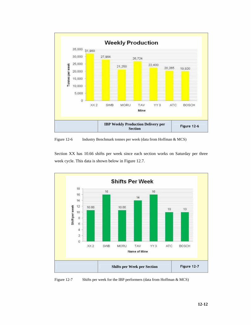
12-12
IBP Weekly Production Delivery per Section
Figure 12-6
Figure 12-6 Industry Benchmark tonnes per week (data from Hoffman & MCS)
Section XX has 10.66 shifts per week since each section works on Saturday per three
week cycle. This data is shown below in Figure 12.7.
Shifts per Week per Section Figure 12-7
Figure 12-7 Shifts per week for the IBP performers (data from Hoffman & MCS)
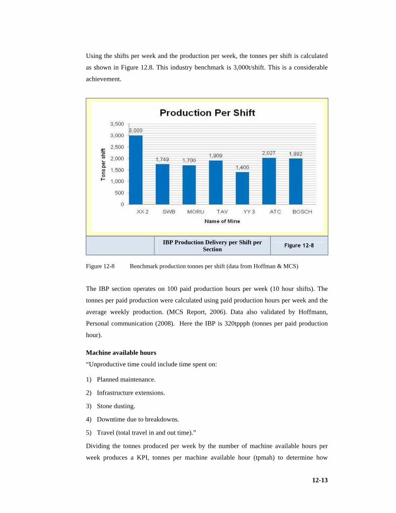
12-13
Using the shifts per week and the production per week, the tonnes per shift is calculated
as shown in Figure 12.8. This industry benchmark is 3,000t/shift. This is a considerable
achievement.
IBP Production Delivery per Shift per Section
Figure 12-8
Figure 12-8 Benchmark production tonnes per shift (data from Hoffman & MCS)
The IBP section operates on 100 paid production hours per week (10 hour shifts). The
tonnes per paid production were calculated using paid production hours per week and the
average weekly production. (MCS Report, 2006). Data also validated by Hoffmann,
Personal communication (2008). Here the IBP is 320tppph (tonnes per paid production
hour).
Machine available hours
“Unproductive time could include time spent on:
1) Planned maintenance.
2) Infrastructure extensions.
3) Stone dusting.
4) Downtime due to breakdowns.
5) Travel (total travel in and out time).”
Dividing the tonnes produced per week by the number of machine available hours per
week produces a KPI, tonnes per machine available hour (tpmah) to determine how
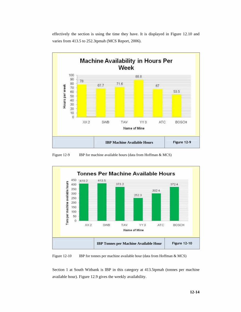
12-14
effectively the section is using the time they have. It is displayed in Figure 12.10 and
varies from 413.5 to 252.3tpmah (MCS Report, 2006).
IBP Machine Available Hours Figure 12-9
Figure 12-9 IBP for machine available hours (data from Hoffman & MCS)
IBP Tonnes per Machine Available Hour Figure 12-10
Figure 12-10 IBP for tonnes per machine available hour (data from Hoffman & MCS)
Section 1 at South Witbank is IBP in this category at 413.5tpmah (tonnes per machine
available hour). Figure 12.9 gives the weekly availability.

12-15
Cutting rate
A machine is deemed to be cutting when it is actively producing coal by sumping in,
shearing down and trimming the roof and floor. The rate at which the coal is liberated is
called the cutting rate and is measured through an electronic monitoring system. The
cutting rate can be deduced by physical measurements.
The best cutting rate of 785 tonnes per cutting hour was achieved by ATC section Inyathi.
Inyathi has a Joy 12HM31 JNA1 CM. Poor cutting rates may be attributable to machine
setup according to the OEM. Cutting rate is shown in Figure 12.11 varying from 825 to
650 tonnes per cutting hour. IBP is 825 tonnes per cutting hour (MCS Report, 2006).
IBP Cutting Rate in tph Figure 12-11
Figure 12-11 IBP for cutting rate (data from Hoffman & MCS)
Away times
The time it takes for shuttle cars or battery haulers to change out behind the CM or ABM
is the away time and the aim should be to use the unproductive time when the CM is
trimming the floor and tramming forward as part of the change out time. The CM’s spade
can hold approximately eight tonnes of broken coal, which means the machine can sump
in and shear down approximately 50cm (0.5m) without the conveyor chain having to run.
The combined time for these activities is 44 to 60seconds as calculated in Table 12.4.

12-16
Table 12-4 Away time (from MCS)
Activity Best Average
Trim Floor 5seconds 8seconds
Raise head while traming
forward
13seconds 15seconds
Sump in 18seconds 24seconds
Shear down 8seconds 13seconds
Total 44seconds 60seconds
If the away time exceeds 60seconds the CM is waiting unnecessarily on the shuttle cars.
If the away time is less than 44seconds the CM is probably not making optimal use of the
cutting cycle. Figure 12.12 ranks the Xstrata ‘away times’ and vary from 24seconds to
81seconds.with the external mines.
“Highest away times can be attributed to:
1) Not following optimal routes.
2) Not having change out points in correct positions.
3) Constraints at feeder breaker.
4) Floor conditions and sweeping” (MCS Report, 2006).
IBP Away Times Figure 12-12
Figure 12-12 IBP Away Time (data from Hoffman & MCS)
The target range should be within 44 – 60 seconds and Section XX-2 meets this
benchmark.

12-17
Relocation time
This is the average time spent per relocation that is the time it takes to move the CM
from one cutting position to the next. Figure 12.13 gives the relocation benchmark and
values vary from 19 minutes to 23 minutes. This consists of actual tramming time as well
as time spent on activities such as cable work, face preparation and pick changes (waiting
time). The IBP is shown in Figure 12.13 and has a value of 14 but it should be noted that
factors such as pillar centres or linear layouts can significantly influence this.
The ratio between the two (tram to wait ratio) should be equal to or greater than 0.5. Tram
to wait ratios are depicted in Figure 12.14 and ranges from 0.78 to 0.22. Note 0.5 means
for every one minute spent on tramming two are spent on cable suspension, cable moving
or changes and pick changes. ‘Wait’ in this context is to stop and not weight (mass x
gravitational acceleration). (MCS Report, 2006). Data also validated by Hoffmann,
Personal communication (2008).
IBP Relocation Time Figure 12-13
Figure 12-13 IBP for average time per relocation (data from Hoffman & MCS)
Relocation efficiency is an extremely important productivity optimisation area since the
number of relocations is directly proportional to the metres cut per shift. A better tram to
weight ratio implies less waiting time. The CM should be moving (tramming) or cutting.
IBP for relocation efficiency is depicted in Figure 12.14 at 0.3.

12-18
IBP Relocation Efficiency (Tram to Stop Ratio)
Figure 12-14
Figure 12-14 IBP for Relocation Efficiency (Tram to wait ratio) (from MCS)
Equipment availability
Based on data provided by the Xstrata group, planned maintenance database, an analysis
was carried out. Average downtime of the CM is shown in Figure 12.15 and varies from
3.2% to 10.6%. Figure 12-16 gives hauler downtime and 12-17 the conveyor downtime.
IBP CM Downtime Figure 12-15
Figure 12-15 IBP for CM Downtime as percentage of shift (data from Hoffman & MCS)

12-19
IBP SC/BH Downtime Figure 12-16
Figure 12-16 IBP for SC/BH Downtime (percentage of shift) (data from Hoffman & MCS)
IBP Conveyor Downtime Figure 12-17
Figure 12-17 IBP Conveyor Downtime (percentage of shift) (data from Hoffman & MCS)
1) Minutes of CM downtime vary from 23 to 64 as shown in Figure 12.15. Note 23
minutes per shift is the IBP recorded at Tavistock by Section 3. This section uses an
ABM30”. (MCS Report, 2006). Data validated by Hoffmann, Personal
communication (2008). The IBP for shuttle cars and battery haulers is 9 minutes per
shift. Section YY on a 3 shift cycle has set the benchmark at 9 minutes per shift or
1.7% of shift time.
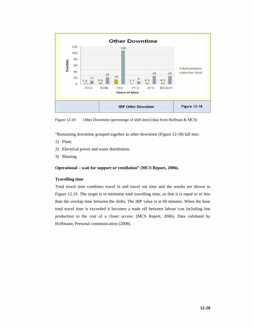
12-20
IBP Other Downtime Figure 12-18
Figure 12-18 Other Downtime (percentage of shift time) (data from Hoffman & MCS)
“Remaining downtime grouped together as other downtime (Figure 12-18) fall into:
1) Plant.
2) Electrical power and water distribution.
3) Blasting.
Operational – wait for support or ventilation” (MCS Report, 2006).
Travelling time
Total travel time combines travel in and travel out time and the results are shown in
Figure 12.19. The target is to minimise total travelling time, so that it is equal to or less
than the overlap time between the shifts. The IBP value is at 60 minutes. When the hour
total travel time is exceeded it becomes a trade off between labour cost including lost
production to the cost of a closer access. (MCS Report, 2006). Data validated by
Hoffmann, Personal communication (2008).

12-21
IBP Travelling Time (In & Out) Figure 12-19
Figure 12-19 IBP for Total Travel Time (data from Hoffman & MCS)
Cutting time
The average cutting time at each section per shift is depicted in Figure 12.52. The targets
of 260 minutes per shift need to be maintained in perspective (MCS Report, 2006). The
best achieved is at Boschmans’ Indlovo section which was 180 minutes and second best
Ingala section 175 minutes.
12.1.3 Production international review
A case study of 11 mines in the USA, where systematic support is installed at more or
less the same density as the Xstrata experience was conducted. “Results indicate that
there are at least four mines in the USA that are consistently achieving between 2,800 and
3,200 tonnes per shift. This is very similar to SA best practice”. (MCS Report, 2006)
“The best bord and pillar sections in Australia can be found at Clarence Colliery which is
producing approximately 2.25Mtpa from three CM sections at an average of 750,000tpa
per section”. (MCS Report, (2006).
Figures 12-20 and 12-21 display USA conditions performances in mines with similar
conditions to the South African Mines. The Mining height is given and the haulage type
be it SC, CH or BH as are the shift cycles 1PIM means one production shift and one
maintenance shift per day, while 2Pmeans two production shifts per day. Super sections
have 2CMs available in the section.

12-22
USA Benchmark Production Delivery per Annum
Figure 12-20
Figure 12-20 Benchmarking USA tonnes per annum (data from Hoffman & MCS)
USA Benchmark Production Delivery per Shift
Figure 12-21
Figure 12-21 Benchmarking USA tonnes per shift (data from Hoffman & MCS)
Note: There are wall faces that produce 650,000tpm namely, Beltana Highwall section of
Bulga Opencast Colliery, NSW.

12-23
Industry (IBP) and group best practice (GBP) summary
Records are not the focus but consistent average performance is. Today’s records do
become tomorrow’s standards if continuous improvement is applied.
Table 12-5 IBP and GBP Summary (from MCS)
KPI IBP
Monthly Production (Tonnes per month)(tpm) 129,000
Weekly Production (Tonnes per week)(tpw) 32,000
Shift Production (Tonnes per shift)(tpshift) 3,000
Production per hour (Tonnes per paid production hour)(tppph) 320
Machine available hours per week (mahpw) 89
Tonnes per machine available hour (tpmah) 413
Cutting rate (tph) 825
Away time (seconds) 45
Average relocation time (minutes) 14
Tram to wait ratio (minutes) 0.7
CM downtime min per shift (minutes) 27
CM downtime % of shift (%) 4.5
Hauler (SC/BH) downtime min per shift (minutes) 9
Hauler (SC/BH) downtime % of shift (%) 1.7
Conveyor downtime min per shift (minutes) 9
Conveyor downtime % of shift (%) 1.7
Other downtime min per shift (minutes) 9
Other downtime % of shift (%) 1.7
Travel time per shift (minutes) 60
The group best practice is summarised in the Table 12.6. Production is mostly influenced
by:
1. Plunge depth (maximum allowed cut out depth from the last through road owing to
ventilation requirements Stringent controls may lead to force exhaust ventilation
systems being imposed, this will in turn influence production.
2. No.4 Seam vs. No.2 or No.5 Seam in South Africa. Mining conditions are more
difficult in No.2 Seam and much more difficult in No.5 seam. The No. Seam coal is
generally harder and impacts on pick efficiencies and therefore CM performance. The
No.5 seam has lower seam height and poor floor and roof conditions and will put
pressure on production rates. This may however be off-set by increasing yield for
maintenance of saleable tonnes. (MCS Report, 2006).

12-24
12.2 Conclusion
1) It is critical that managers have an appreciation of delivery levels and it was a major
aim of this research to quantify this.
2) The Benchmark performances and the levels of delivery that could reasonably be
expected from sections have been presented as values aligned to key performance
indicators. Refer Table 12.9 for summary.

13-1
13 GUIDELINES TO COLLIERY DESIGN AND OPERATION
13.1 Have a Competent Appreciation of Mine Planning and Design
This researcher is a member of the Mine Planning and Design Steering Committee of the
Mining Qualifications Authority (MQA). Industry has identified the need to develop
these skills among certain echelons of industry and it is an aim of this research to identify
the elements of a guideline which will be the focus of planned future and higher research.
Industry has previously considered the Mining Engineers qualification to be the
overriding requirement to prove knowledge competency in the Mine Planning and Design
(MP&D) arena.
Industry now wants formal qualifications to ensure planners are developed with the
correct skills base and hence a need for qualifications in MP&D from the mining
companies’ perspective is confirmed and desired.
Some of the reasons for this demand are due to:
1) A general lack of confidence in plans.
2) Plans based on volume rather than value and risk.
3) No formal qualifications exist at present (only some unit standards in the MQA mine
overseer and production supervisor qualifications and some content in the B.Eng.,
B.Tech. and ND at Universities, and the Certificate in MRM presented at Wits
University.
4) There are certain ad hoc commercial programmes such as Whittle and GMSI etc.
5) There is a perception of no identified career pathway for MP&D practitioners.
6) Mining companies need competent MP&D practitioners in terms of the Mine Health
and Safety Act No. 29 of 1996 (MHSA).
7) There is diversification of mining methods which places demands on planners and
designers.
8) There is an identified skills shortage in the MP&D practice area.
9) New reporting requirements, such as (SAMREC) requires, Mineral Exploitation
Plans to comply with Materiality, Transparency and Competence requirements.
10) New skills and capabilities need to be brought into MP&D competency requirements,
especially an economic and risk focus.

13-2
11) Redefinition is required on planning structures and roles.
There are current developments which impact on MP&D needs:
1) There is focus on the impact of Mine Planning and Design competency and skills on
the creation of safe and healthy work places.
2) The need for competent plans that define the conversion of Mineral Resources into
Mineral Reserves through Codes such as SAMREC, NI 43-101, JORC etc.
3) The need for plans that can be used for the valuation of Mineral Assets, for future
international accounting requirements, and the valuation of mineral assets in
accordance with Codes such as SAMVAL.
4) There has been a stated need for mine plans to be more reliable and to have more
continuity and may be audited.
5) The need for mine plans to better reflect and support the sustainability of the mining
industry, given price volatility, financial uncertainty and increasingly complex
mining methods and coal deposits.
6) The need for the South African mining industry to be globally competitive.
The MHSA sets specific responsibilities on the Manager and Owner to appoint
Competent Persons for:
1) The mine planning processes and systems.
2) Safe mine planning layouts and designs.
3) Safe and healthy workplaces.
4) Due diligence in application of plans and designs (e.g. safety factors).
5) To ensure compliance with codes of practice.
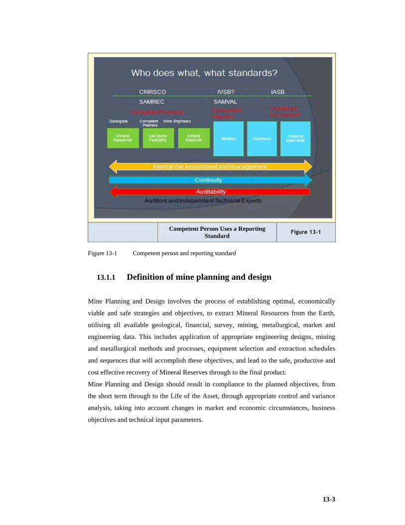
13-3
Competent Person Uses a Reporting Standard
Figure 13-1
Figure 13-1 Competent person and reporting standard
13.1.1 Definition of mine planning and design
Mine Planning and Design involves the process of establishing optimal, economically
viable and safe strategies and objectives, to extract Mineral Resources from the Earth,
utilising all available geological, financial, survey, mining, metallurgical, market and
engineering data. This includes application of appropriate engineering designs, mining
and metallurgical methods and processes, equipment selection and extraction schedules
and sequences that will accomplish these objectives, and lead to the safe, productive and
cost effective recovery of Mineral Reserves through to the final product.
Mine Planning and Design should result in compliance to the planned objectives, from
the short term through to the Life of the Asset, through appropriate control and variance
analysis, taking into account changes in market and economic circumstances, business
objectives and technical input parameters.

13-4
13.1.2 Integrated planning must be adopted
Short, medium and long term planning must be integrated. It is also necessary to ascribe a
measure of value (valuation) to each. The planners must ensure that a clear purpose is
ascribed to each level of planning. It must have well defined objectives. Compliance to
the Codes must be monitored and optimisation and risk analysis must be done.
Plans must be resourced requiring a budget, therefore planning and budgeting are not
separate processes. It is a dynamic process which allows continuous improvement and
adaptation.
The Life of Mine plan must have a Net Present Value (NPV). Internal Rate of Return
(IRR) and Payback must be considered.
Table 13-1 Planning levels and outcomes
Level of Planning
Outcomes
Scenario Planning
Defines long range markets and scenarios for strategic planning
Strategic Planning
Defines strategies to position company within defined scenarios
Strategic Mine Planning
Defines optimal combinations and options for assets
LoM III Planning
Defines exploration and development requirements to bring Inferred Resources
and Blue Sky forward and defines new capital projects for project evaluation.
May be Concept Study.
LoM II Planning
Defines exploration and development projects to bring Indicated Resources
forward and incorporates capital projects for approval. May be PFS.
LoM I Planning
Single definitive plan for Mineral Reserve declaration and Asset Valuation
based on Measured Resources and Proven Reserves. Defines broad sequence
for 5 year and 24 month plans. May be BFS.
5 Year Planning
Defines Ore Reserve development requirements to support LoM and 5 year
exploitation and optimisation requirements.
24 month Planning
The Best Practice business plan that defines business units output and costs and
budgetary and resource requirements.
6 Month Planning
Defines logistical planning and requirements to realise monthly production
targets.
Monthly Planning & Reconciliation
Monthly production plans & reconciliation.

13-5
The planning levels involve scenario planning an operation that is taken seriously by
people such as Clem Sunter who through numerous publications has encouraged people
to be ‘foxes’ and not ‘hedgehogs’ and maintains that South Africa is in the ‘premier
league’ but is required to monitor the ‘flags’ of what could send us to the ‘relocation
zone’. These flags are ‘nationalisation’, ‘health care (securing quality medical
practitioners)’, ‘freedom of press and media’, ‘education’, and ‘level of crime’. ‘Scenario
planning’ is followed by ‘strategic planning’, ‘strategic mine planning’, and levels of ‘life
of mine planning’ (concept-, prefeasibility- and bankable feasibility- studies or LoM III to
LoM I), ‘five year planning’, ‘twenty-four month planning’, and ‘six month planning’ in
detailed ‘twelve month plans’. This culminates in very specific ‘monthly planning’ and
‘reconciliation’. It should be added that strategic planning determines Vision and Mission
and takes an in depth look at strengths, weaknesses, opportunities and threats (SWOT)
through an analysis process.
Coal mining companies deal with Mine Planning and Design (MP&D) through using
planners with specialised knowledge of the industry. They understand the planning levels
and outcomes of the planning process (displayed in Table 13-1 and Figure 13-2) the
competency requirements and Codes for the MP&D processes which is graphically
presented in Figure 13.1). These planners and designers must understand the drivers of
value. The plans need, in the current socio-political climate, to have a strong
environmental focus. There must be a strong link to finance including strong links to
markets and customers and ensure a quality assurance system is implemented.
Integrated Mine Planning Figure 13-2
Figure 13-2 Integrated Mine Planning

13-6
13.2 Secure Prospecting and Mining Rights
A Prospecting Right will normally need to be secured and a formal application process
needs to be followed. This route has been clearly documented in (Fourie & van Niekerk,
2001) also known as Col814. In this work the authors depict the systematic planning and
design process for underground coal mining operations from inception to closure during
which the process of attaining a prospecting permit and a mining authorisation is outlined
in detail. The Department of Mineral Resources in South Africa (DMR) or other
Authority in neighbouring states will require a Mining Work Programme (MWP), a
Social and Labour Plan (SLP), and the Environmental Management Plan Report (EMPR)
before they will grant a Mining Right (Mining Licence).
13.3 Proceed with Understanding the Role of the Mining Engineer in the Mine Life Cycle
Col 814 gives thought to the ‘Investigative Studies’ during which a ‘market analysis’ is
undertaken and the ‘geological target area’ is identified. A ‘literature survey’, ‘regional
mapping’, ‘remote surveys (geophysical)’ and ‘surface surveys’ are concluded. The ‘legal
status of the target area (Tenure)’ needs to be identified and the ‘Environmental Impact
Assessment (EIA)’ conducted. A ‘conceptual economic study’ is undertaken before a
prospecting permit is secured. In this researcher’s experience, a full concept study
normally follows when some geological data, allowing the construction of the initial
geological model, has been attained.
A ‘Prefeasibility Study (PFS)’ and the ‘Feasibility Study (BFS)’ leads to the development
of an external report or bankable report (bankable feasibility study, (BFS)) and the
attainment of a mining authorisation. It has become accepted that the FS is a BFS and the
bankable has become redundant, modern usage refers only to FS as an external report. It
should be noted that there are strict requirements for external reporting (public reports).
The ‘Mine Establishment and Construction Phase’ follows and then the ‘Operational or
Production Phase’. The ‘Decommissioning and Mine Closure Phase’, with the required
‘Mining Reports’ and ‘Mine Closure Planning Report’ are mandatory. During the
preparation for the operational phase the mining engineer may be involved in mine
planning as most of the design activities are completed earlier and also may be involved
in the training strategy of the personnel (development of training materials for the method

13-7
selected for example). The engineer would in some cases be implementing new methods
and the skills to function with these methods need to be developed and promoted.
Fourie and van Niekerk (2001) state “The planning and design process throughout the life
cycle of any mining project typically consists of the following five unique and
identifiable phases:
1) Phase 1: Project data collection and investigations.
2) Phase 2: Evaluation, planning and design.
3) Phase 3: Construction and mine establishment.
4) Phase 4: Mining operations.
5) Phase 5: Mine decommissioning and closure.
They further list the design process as:
“The planning and design process associated with each of these phases consists of the
following typical elements:
1) Identification of desired outcomes.
2) Statement of all planning and design assumptions and premises.
3) Identification of planning and design risks.
4) Identification of planning and design restrictions and constraints.
5) Statement of planning and design criteria to be used.
6) Data collection.
7) System planning.
8) Hazard identification and risk assessment.
9) Evaluation of options.
Integrated Mine Planning Figure 13-3
Figure 13-3 Planning and design process (from Fourie & van Niekerk, 2001)

13-8
10) Identification of the best or preferred options.
11) System design” (Fourie and van Niekerk, 2001).
13.4 Accounting of Minutes in the Production Process and the 280 Minute Cutting Cycle Target.
The quantification of the process in minutes is essential when dealing with the mining
operation and mining cycles and it is this evaluation that is carried through into the mine
planning and design exercise.
All mines will find the necessity to measure availability and utilisation of mining plant
and systems. These controls will require the accounting of minutes in the production
process. Targeting cutting times of 280 or 350 minutes per shift in the 8 hour or 9 hour
shift times available is essential if productivities are to approach the 2Mtpa target. It is
apparent that the 1Mtpa level is still very elusive.
Minute management is essential if management is to control the production process
effectively. The current 180 minute benchmark will not improve to 280 minutes if the
‘soft issues’ of ‘Systems Thinking’ are not implemented.
13.5 Adopt a System of Best Practice SOP’s to Control Quality, Costs, Delivery, Safety and Morale.
SOPs dealing with QCDSM, quality, costs, delivery, safety and morale are paramount in
ensuring objectives are met.
The mine must produce procedures to enable:
13.6 Apply an Effective Continuous Improvement Culture- the Twenty Keys Strategy.
Continuous improvement strategies help focus the workforce. The Kobayashi 20 Keys are
effective and have been discussed in the section on soft issues.

13-9
13.7 Implement a Realistic Appreciation of Production Delivery
Productivity levels have been well determined and may be used by planners to schedule
their production build-up. Driven by the need, to better utilise scarce resources, mine
operators understand the need to progress to higher extraction methods.
Many of the remaining coal resources are in thinner seams requiring a paradigm shift in
methods we were comfortable with in thicker seams. It should be realised that risks are
exacerbated in low seam (thin seam) environments.
The best performing longwall face recorded is situated in NSW Australia delivering in
excess of 5.5Mtpa and averages 460,000tpm it delivered 7.5Mt in the 2007 production
year. This is Beltana Colliery which operates a highwall entry mine. The defining
parameters are powerful equipment applied in wide faces (300, and 400 – 500m) of
optimal panel length (3,000m). The lean and mobile or portable format of this operation
is very effective. The manpower complement is also kept very lean.
Fewer mines are currently applying pillar extraction techniques and where wall mining
conditions are suitable, wall mining is the preferred method although it remains capital
intensive. Depth to floor and required high extraction rates remain the main drivers.
Pillar extraction methods have followed from the previously widely applied Rib-pillar or
Wongawilli methods. Productivity levels do not show significant improvement on partial
extraction methods. Rib-pillar (RPE) has lost favour in South Africa but the derivative
(Wongawilli) is preferred in Australia when secondary pillar extraction occurs.
The better performers found in South Africa involve the ‘Nevid’ method of pillar
extraction as this provides a means of managing horizontal stress found in the mining
environment and allows pillar extraction above 3.5m mining height.
(Horizontal stress is however not fully understood in collieries and further research is
needed in this area). Modifications arise were smaller and older pillars need to be
extracted. The methods do not fully recover all coal and partial pillar extraction has
become the trend. Gericke has proposed a sequence for extracting small pillars.
Pillar extraction methods have evolved to derivatives of ‘pocket and fender mining’ with
the leaving of snooks as common practice. Continuous miners are the preferred tool in
this exercise.
Partial extraction or bord and pillar mining is still favoured as it is believed to offer less
risk. It offers competitive productivity levels, with reduced subsidence, if any. Wall
mines will still apply this method in remnants that cannot accommodate suitable wall
panels or where blocks are significantly disturbed. Partial extraction or bord and pillar

13-10
mining is further necessary in primary and secondary developments. Continuous miners
are preferred with conventional (blasting and mechanical loading) systems few and far
between.
Linear panel layouts are finding increased favour as demonstrated in Magatar methods.
The advantage accrues by placing narrow roadways in close proximity and parallel to
each other, with no use of support in the roadways, the splits are generally cut forming
diagonal pillars in certain layouts.
The coal moving system behind the continuous miner is open to much debate. Continuous
haulages offer the greatest productivity levels but their application is less flexible. The
best recorded performance is 160,000tpm at Syferfontein but it is noted that this is a long
standing statistic. The average is of the region of 80,000tpm. Sandvick the Voest Alpine
agent in South Africa maintain that the ABM30 now delivers 110,000 to 130,000tpm
regularly. They maintain a control room in Delmas, were production reports are
centralised via LAN.
Shuttle cars (batch haulers) of the battery powered or trailing cable variety offer different
levels of flexibility in panel design but have capital and operating cost constraints. Diesel
impacts significantly on the underground environment and air quality. Better producing
sections are equipped with large capacity units (20t) and generally a minimum of three
units are needed per CM. The free-flowing battery powered units appear more productive
than the cable reel equipped systems.
Operators generally apply 10 or 17 shifts/week cycles on two or three shift systems. Best
performers deliver of the order of 80,000 to 100,000tpm from a CM section. The average
deliveries are lower at 65,000tpm.
The 1Mtpa production target from one CM is still very elusive as only seven CM sections
in South Africa where on target to attain this tonnage during 2009.
In the low seam (5 Seam) environment using Sandvick’s Voest ABM10 daily linear
advances reported amount to 80mpd (metres per day) with an average of about 53mpd by
Xstrata Coal at the ‘Southstock’ operation using a Rib Pillar Extraction derivative.
13.8 Have a Competent Appreciation of Thick Seam Methods
The Chapter on thick seam mining has addressed the modern trends in thick seam mining.
Methods above 3.5m have finally evolved. Continuous miners such as the 12HM31 have
cutting heights of 4.5m and generally the only constraint is the roofbolter reach.

13-11
Specialised units in the multi-head category can be obtained for heights above 4.5m.
Units may be modified in collaboration with the OEM.
Wall systems have evolved the technology to mine at 6m. Moranbah in Australia has
delivered a case study on the application of large support units coupled with powerful
shearers and can competently deliver the required production tonnage. The research has
identified and quantified the elements that need to be considered when designing the
implementation of a wall system.
Beltana of Bulga delivers a best performance of 7.5Mtpa at an average of 625,000tpm to
rank as Australia’s top wall face and notched industry best practice (IBP).
Chinese methods and the aligned Soutirage method that hybrids with top coal caving
behind the support units may utilise second AFC’s or chutes to recover this coal. The
efficiency of these methods has been challenged and requires further development. But
can access coal beyond the normal channel width or mining height.
Previous work by Lind, Beukes and Galvin had promoted the understanding of thick
seam mining and are some the most valuable works available to the mining engineer who
needs to design thick seam methods and increase resource utilisation.
The NEVID system and its ability to mitigate the reactions to horizontal stresses made
this a suitable method for thick seam pillar extraction.
Secondary mining systems that utilises bottom coaling techniques have still been
considered in numerous applications owing to enhanced safety relative to pillar extraction
methods.
The challenge remains the maximisation of percentage extraction and the use of
sophisticated technology in a risk rich environment.
13.9 Have a Competent Appreciation of Thin Seam Methods.
The chapter on thin seam mining has researched the broad spectrum of methods
historically applied from heights below 1.5m to the difficult 0.6m channel.
The modern low seam continuous miner applications will find greater impact as thicker
resources are depleted. The USA application of this method in medium to thin mining
heights show exceptional production deliveries but the super section concept using two
CM’s is well established.
Methods as varied in application as the ‘Auger system’, the ‘Collins miner’, the ‘Addcar’,
the ‘Spanish plough’ and the ‘Wilcox systems’ are presented. Thin seam mining will
become more significant in the difficult No.5 Seam applications in the Witbank field and

13-12
will probably use ‘Punch mining’ or ‘Augers. Risks associated with the thin seam
environment include managing poor roof, the confined channel and the poor floor.
Low seam miner ABM10 Figure 13-4
Figure 13-4 Thin seam CM
13.10 Have a Competent Appreciation of Mine Modelling Applications.
The quality plots in figures seen in this guideline have been generated with Surfer after
the geological data was captured and ordered on GBIS. The borehole data is transferred
to Micromine where the actual mining modelling and design is developed.
It is essential that this be in the skills base of every operator. Many different packages
have been developed and many are capable of delivering effective solutions.
It is necessary to ensure that the geological modelling, the survey modelling and mining
modelling are compatible. ‘Surpac,’ Micromine, Minesite and ‘Microstation’ with
derivatives such as ‘Cadsmine’ and ‘Mine2-4D’ have been used.
13.11 Understand what Charts and Data need to be Generated to Delineate Pit Limits for the Design.
Those that were needed with the Morupule case study are presented in Figure 13-5 to 13-
16 (some contained in other sections of this chapter). Other charts will be required with

13-13
specific designs but some examples have been presented in the guideline. Critical data
required during the design and that needs to be generated by the engineer is displayed in
Tables 13-2 to 13-4 and are self explanatory.
Floor Elevation Contours Figure 13-5
Figure 13-5 Plan floor elevation (mamsl) contours and palaeo-valley axis (from Dougall et
al, 2009)
Isopachs Figure 13-6
Figure 13-6 Plan showing thickness contours (from Dougall et al, 2009)

13-14
CV Contours Figure 13-7
Figure 13-7 Plan Showing In-situ calorific value (air-dried uncontaminated) ad. uc.
contours (from Dougall et al, 2009)
Ash Content Contours Figure 13-8
Figure 13-8 Plan showing In Situ Ash Content contours (Full seam thickness) (from
Dougall et al, 2009)
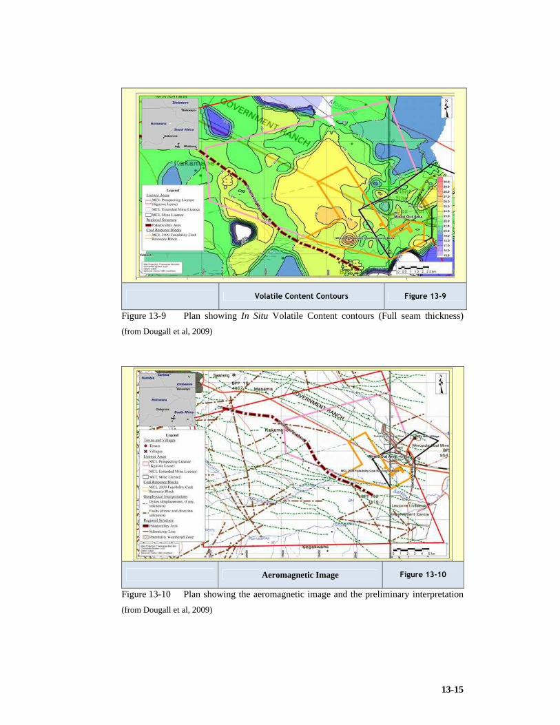
13-15
Volatile Content Contours Figure 13-9
Figure 13-9 Plan showing In Situ Volatile Content contours (Full seam thickness)
(from Dougall et al, 2009)
Aeromagnetic Image Figure 13-10
Figure 13-10 Plan showing the aeromagnetic image and the preliminary interpretation
(from Dougall et al, 2009)

13-16
Table 13-2 Classified Coal Resource Estimates at 4.2m mining height within the Project
Area (RD 1.51) (from Dougall et al, 2009)
In South Africa we need to use the SAMREC Code for the reporting of resources and
reserves and these statements have to be signed off by a competent person. The JORC
code was used for Morupule as the field was considered uncomplicated. The guidelines
require fewer boreholes per hectare. The eventual classification is ‘Proved’ or ‘Probable’
reserves but the proved value is associated with the measured resource.
The proximate values range from inherent moisture (IM), Volatiles (Vols), fixed carbon
(FC), Ash, calorific value (CV) to total sulphur (TS) and the average relative density
(RD) of the sampled coal. This may be needed for the full thickness or specifically for a
channel (4.2m mining height).
Table 13-3 In Situ Coal Qualities (Full Seam Thickness) (Project Area) (Grid Info)
(from Dougall et al, 2009)
Classification Category Area Mineable In Situ Tonnage
(4.2m Mining Height)
Mineable In Situ Tonnage (10% Geo loss & 5% Model error ) (4.2m Mining Height)
(Mm2) (Mt) (Mt) Measured 20.844 132.196 113.027 Indicated 8.48 53.78 45.98 Inferred 3.0 19.2 16.4
TOTAL 32.3 205.2 175.4
RD IM Vols FC Ash CV TS
ad uc t/m3 % % % % MJ/kg %
Min 1.45 3.56 17.17 36.84 15.82 17.94 0.18
Max 1.69 6.12 28.14 55.22 35.99 27.44 3.45
AVG 1.51 4.77 23.49 50.54 21.21 23.41 1.09

13-17
JORC Classification Measured, Indicated, Inferred Resources, or Proved & Probable
Reserves Figure 13-11
Figure 13-11 JORC Classification of Measured, Indicated and Inferred Coal Resources (from
Dougall et al, 2009)
Exploration Boreholes Figure 13-12
Figure 13-12 Exploration boreholes (from Dougall et al, 2009)

13-18
Feasibility Study Mine Layout Figure 13-13
Figure 13-13 Feasibility Study Mine Layout (from Dougall et al, 2009)
Table 13-4 Conversion of In Situ Coal Resources to RoM Coal Reserves (4.2m) (from
Dougall et al, 2009)
Mt Resource Utilisation
Reserve Utilisation Remarks
Resources
All coal that meets thickness and quality cut-off parameters within an target area
GTIS (Full Seam) Project Area 425
Area(32.5) x RD(1.51) x Surfer Model Seam Thick(8.7)
TTIS (Full Seam) 382 90% 10% Geological loss MTIS Resource (Full Seam) 363 85% 5% Model Error Reserves Needs a mine plan to calculate the volume MTIS Reserves (4.2) 205 48% Area(32.5) x RD(1.51) x h(4.2) Practical MTIS Reserve
175 41% 85%
Determined by Micromine model (layout loss + adverse operation conditions loss + surface restriction loss + pillars + barriers + mining efficiency + contamination) to RoM
RoM Reserves 77 18% 38% LoM @ 3.6 Mtpa = 22yrs Probable 27 Proved 50 Measured 65%

13-19
13.12 Understand the Coal Qualities Raw and Beneficiated and Beneficiation Processes and Potential Product Qualities for the Target Resource.
It is necessary to define the qualities derived from the borehole sample data
systematically. Table 13-4 depicts the type of table summary required. Figure 13-14 is a
useful graphic lot of the qualities that may be delivered over the life of the project and is
generally required in the report. The specific data is from the Morupule case study.
Quality Plots Figure 13-14
Figure 13-14 RoM coal 3.6Mtpa Qualities ad. uc. (from Dougall et al, 2009)
13.13 Have a Competent Appreciation of Previous Research
Generally these reports get trapped in University libraries and in those of research
organisations. Valuable concepts are available in these documents. The realms of
knowledge management require that mining engineers build a data base of these concepts.
We unfortunately often have very short memories.
This research has found numerous works that have cognitive contribution but
unfortunately many date back beyond a decade. This implied that much of the knowledge
is due for updating. Many references date back as there is nothing published more
recently.

13-20
13.14 Consider Relevant Factors and be Systematic when Deciding on the Implementation of Specific Mining Systems.
Chapter 6 of this research a dealt with the industry available knowledge in detail and
work done in the 1980’s by Fauconier and Kirsten (1982) is still applicable to method
selection and cannot be ignored. This is done in context with the broad categories of
economic, technological, and geological perspectives.
Factors specifically considered as endorsed by leading consultants include: Production
rate; Flexibility; Extraction; Influence of geology; Influence of floor; Operating costs;
Capital costs; Safety; Environmental impact; Selectivity; Continuity of production;
Ventilation required; Proven technology; Ancillary equipment; Development; Skills of
personnel; Impact of change; Lead time to implementation.
Again the independent works of Lind (2003) Beukes (1992) and Galvin (1983) must be
incorporated to enable effective decision making. A process defined by the prefeasibility
study of Morupule colliery and used by consultants DRA and SRK is an effective
decision making tool (Selection matrix method).
13.15 Maximise and Optimise Resource and Reserve Utilisation.
To enable this, the engineer has to provide and effective sequence and schedule illustrated
Figure 13.15 and 13.16. The design also needs to move to secondary extraction processes
to enable optimum reserve utilisation.

13-21
Mining Sequence Figure 13-15
Figure 13-15 Mining sequence (from Dougall et al, 2009)
Mining Schedule Figure 13-16
Figure 13-16 Individual CM mining areas and schedule (from Dougall et al, 2009)

13-22
13.16 Follow the Recognised Mineral Reporting Code and Guidelines to Describe the Resources and Reserves to Achieve an Effective Geological Model.
The SAMREC code is the preferred code in SA.
Relationship Resources & Reserves Figure 13-17
Figure 13-17 Relationships between Exploration Results, Mineral Resources and Ore
Reserves (from the Samrec Code, 2007)
13.17 Ensure a Comprehensive Understanding of Hydrological Factors that Impact the Target Area.
Chapter 4 on hydrology gives an in-depth discussion on hydrological issues. It is essential
that the design engineer understands the impacts of this category. It will influence
delivery and mining conditions. Hydrological factors could leave a scar on product
qualities if not understood and mitigated against.
13.18 Ensure a Comprehensive Understanding of Geotechnical Factors and Rock Engineering Criteria for the Design.
Critical geotechnical parameters should be defined. This may be started remotely with
geophysical data collection using remote surveys prior to a prospecting licence being

13-23
awarded, however, drilling is the only secure way of attaining enough geotechnical data
from the cores by analysis. This has been dealt with in Chapter 5 of this research.
13.19 Ensure a Comprehensive Understanding of the Environmental Impact and Develop an Effective Strategy for Environmental Management.
Mines have to take cognisance of these requirements. This element has the potential of
cutting design objectives short when problems arise. Sigma Colliery’s life was cut short
on its Northwest project due to environmental opposition and court litigation. Carbon
budgets will play a significant role in future operations. Technology may need to be
developed and used to control green house gas emissions (GHG) as has been announced
in the USA, this is referred to as ventilation air methane (VAM) management.
13.19.1 VAM
The VAM abatement equipment to be installed at the mine will capture and destroy the
methane released during the mining process that would otherwise escape to the
atmosphere through the mine's ventilation system.
Consol Energy's Enlow Fork mine is an active underground coal mine that produces
approximately 10 million tons of coal a year. The project is designed to reduce the mine's
VAM emissions by the equivalent of 190,000 tonnes (metric tons) of carbon dioxide
(tCO2e) a year and is estimated to be operational in the second half of 2010. Methane is a
greenhouse gas that is 21 times more effective at trapping heat than CO2. Globally, VAM
emissions from coal mines amount to approximately 300 million tCO2e each year.
Steven Winberg, vice president of research and development at Consol Energy, said: "If
the US intends to reduce greenhouse gas emissions, it will have to be addressed on a
broad front dealing with many different sources of GHGs. We already have a large coal
bed methane production business that removes methane from coal seams before mining,
producing a valuable fuel. With this agreement, we will deal with methane that is released
from a coal seam during the mining process."
This researcher is of the opinion that industry would have to focus on carbon capture and
sequestration. In addition to the capture of methane from coal seams (methane drainage)
and from mine ventilation air, including the capture of CO2 from high pressure coal
combustion equipment, the evaluation of CO2 storage in unmineable coal seams or in

13-24
other deep (>700m) geological formations which in southern Africa unfortunately
appears to be offshore in the exploited gasfields.
The project at Enlow Fork mine is said to be the first of a number of VAM abatement
undertakings that Green Holdings expects to take in the US in anticipation of a growing
market for carbon offsets to be generated by the projects. Jerry Gureghian, CEO of Green
Holdings, said: "We are pleased to be working with Consol Energy, the largest
underground coal mine owner and operator in the US, on this important project." Green
Holdings will supply capital, operate the unit and will be responsible for selling the
emissions reduction credits. Consol will provide the ventilation air fan, site and technical
support (South African Coal Roadmap correspondence).
13.20 Benchmark your Competitors and Other World Class Achievers.
This dissertation has dealt with these concepts in depth. By understanding world class
performance we may eventually emulate it. Benchmarking also helps to create realistic
delivery expectations.
13.21 Consult and Use the Leading Engineering and Science Consultancy Professionals to Provide a Neutral and Impartially Independent Perspective for the Design.
When doing external reporting and fund generation this becomes mandatory. The benefit
to management in efficiency enhancement is due to a value payback and enhanced skill
application. It ensures quality in the design. They generate independent competent
person’s reports and are dexterous and experienced in studies for concept, prefeasibility
and feasibility application.
13.22 Elements of an Effective Design or Plan
The South African Colliery Managers Association identified the requirements of a good
mine plan and include the following considerations:
1) Primary entries must be as long as possible to the extreme of the reserve, taking into
consideration all geological information, surface structures and future shaft positions.

13-25
2) Secondary entries as long as possible to the extreme of the reserves and with the
panel lengths designed for optimal section conveyor belt capacities and lengths. This
varies from 900 to 1,200m.
3) Panel Widths are dependent on depth and hence pillar size allowing 5, 7, 9 or 11
bords (roadways) in panel and is also constrained by the length of trailing cables
which should be about 180m. With effective placing of switchgear this
accommodates a width of 360m but strata stiffness is a major player.
4) Generally one return airway per CM is required in the primaries with at least one
more intake than the amount of return airway (four CMs will require four return
airways in the main and there should be four plus one intakes (five) hence the
primary should be made up of at least nine roads. This is a function of the cross
sectional area of the roadways and the quantity of air that needs to be supplied to the
section.
5) Mining should be concentrated for easy supervision and management.
6) Sub shafts should be well positioned for men and material and kept close to
production areas. These shaft positions are related to a radius of about 8km for men
and materials (ideally 5km) and 15km for coal. Men should however be in section
within the 30 minute travelling time.
7) There should be additional pit room available for replacing three sections
immediately.
8) Reserves must be opened up with primary development for at least 1km in front of
existing workings hence proving the reserve and giving knowledge of minability and
qualities.
9) Layouts must approach known geological disturbances at approximately 90º.
10) Secondary panels must avoid mining longitudinally or parallel to or with special
areas.
11) The planner should not target good quality or good ground only but should ensure a
blended mix with poorer reserves.
12) Any decision or reason for not mining a section of reserves should be recorded on the
plan for future reference by others.
13) The mine should cater for well planned bunkers for equalising the coal flow.
14) Reserve and potential geological disturbances should be well covered with horizontal,
directional drilling and vertical drilling.
15) Critical surface structures (dams, rivers, conveyor belts, pylons, tar roads, towns,
irrigation fields, boreholes, stock pile areas, dumps, farm houses, shaft areas and

13-26
mining restricted areas) must not only be shown but also highlighted with a suitable
colour on plans.
16) No total extraction should be planned under any streams, rivers, dams, or any other
water bearing places.
17) The planner should place primary developments under surface structures with a high
safety factor required of the supporting pillars.
18) There should be different demarcations for mine boundaries and reserve boundaries.
19) Ventilation simulations should be done and the limits shown on a plan for present and
future situations.
20) There must be independent intake and return airways provided.
21) Layout should consider the objective of minimum air crossings and other restrictions
in ventilation flows.
22) Provision must be made for water compartments with a single entrance at the highest
point.
23) As far as possible, mine down dip to keep water at lowest point when doing total
extraction.
24) Planned infrastructure must be sufficient for future capacities and expansion.
25) A cost evaluation and budget should be prepared for each alternative plan.
13.23 When Leading a Project or Operation be a Great Leader
1) Lead by example. Establish a direction for the team to follow. Be exemplary in all
you do, apply good and clean communication, have a neat dress code, and be honest
in all areas, displaying consistent enthusiasm. Be punctual.
2) Be a good listener. Be respectful and listen intently to both work and personal issues.
Immediately act on the communication and resolve issues were possible.
3) Have empathy. Be available or accessible in times of need. Pass on credit to the team
while owning the responsibility for their failures. Be a person of integrity and values
and the team will follow suit.
4) Create harmony. Avoid arguments and protect team members from blame. Create a
fun environment. When you are having fun the team is having fun and if the team is
having fun the customer is having fun and this must lead to more business.
5) Communicate. Talk to the team. Let them know what is happening in the business
and with clients. Give feedback from meetings you attend. If they feel part of the
business they feel important and become empowered to give more of themselves.

13-27
6) Make more leaders. Grow and develop those around you to your level. Delegate
certain of your responsibilities to the relevant and capable team member. Do not
attempt to pass accountability.
7) Your team members are your greatest assets. Manage their potential, capabilities,
time and talents.
8) Be transparent. Keep your team informed and allow them to participate, to give
feedback and make comments. Never keep them in the dark. Allow them to be part of
the solution and share in the rewards. Let them feel what they say and think is
important.
9) Be a role model. A good leader must serve as a role model to the team members.
Demonstrate the right attitudes, strong values and subconsciously they will adapt to
the same standards.
10) Managers vs. leaders. A manager can be a leader. Leaders focus on innovation and
growth and continuously challenge the status quo. Managers maintain the status quo.
There is a time to manage and a time to lead. Allow more of your time to lead.
13.24 Understand and Use Competency Effectively
Competent Person
Means a person, who demonstrates the ability, specified in terms of knowledge, specific
skills or an integrated cluster of skills, capabilities and values, executed within an
indicated range or context and to specific standards (SGB Circulars, Personal
Communication, 2010).
The Engineering Profession Act, 2000 provides for categories of registration of
professional, which is divided into:
1) Professional Engineer;
2) Professional Certificated Engineer;
3) Professional Engineering Technologist;
4) Professional Engineering Technician;
Competent persons hold qualifications which have fundamental, core and elective
components as shown in Figure 13-18 (SGB Circulars, Personal Communication, 2010).

13-28
Competent persons have fundamental, core & elective competencies.
Figure 13-18
Figure 13-18 Competent persons model (from MQA)
Practicing persons needs to have Currency of Competency to ensure they are active and
up to date, and may require no licencing, discretionary licencing or mandatory licencing
and this will normally require registration before engineering work may be performed.
This is depicted in Figure 13-19.
Practicing persons licencing and registration alternatives
Figure 13-19
Figure 13-19 Practicing person model (from MQA)

13-29
Engineering qualifications and competencies
Engineering education has evolved to a two stage developmental model. The stage one
formal qualification is followed by a stage two development prior to licencing and
registration although candidate registrations and mentorship will exist as part of this
model. This is displayed in Figure 13-20.
It requires distinctive competencies to perform engineering work associated with a
registered category that include:
1) Investigate and solve problems, design solutions;
2) Use knowledge and technology based on mathematics, basic sciences and
engineering sciences, information technology as well as specialist and contextual
knowledge;
3) Manage engineering activities and communicate effectively;
4) Address the impacts of engineering work, meeting legal and regulatory requirements;
5) Act ethically, exercise judgement and take responsibility.
6) Engineering knowledge and practice expands and changes continually. Professionals
must therefore continually maintain and extend their own competency.
Occupational Qualifications
The term ‘occupational qualification’ is defined in legislation as: ‘a qualification
associated with a trade, occupation or profession, resulting from work-based learning and
consisting of knowledge unit standards, practical unit standards and work experience unit
standards. The purpose of an occupational qualification is to qualify a learner to practice
an occupation, or a specialisation related to an occupation, reflected on the Organising
Framework for Occupations (OFO). The OFO is a skill-based coded classification
system, which aims to encompass all occupations in the South African context and is
derived from the International Standard Classification of Occupations (ISCO), developed
by the International Labour Organisation (ILO).
There are eight major groupings in the OFO:
1) Managers.
2) Professionals.
3) Technicians and Trade Workers.
4) Community and Personal Service Workers.
5) Clerical and Administrative Workers.
6) Sales Workers.
7) Machinery Operators and Drivers.
8) Labourers and Elementary Workers.

13-30
Two Stage Developmental Model Figure 13-20
Figure 13-20 Two stage developmental model (from MQA)

13-31
Major Groups of OFO broadly mapped
against NQF levels Figure 13-21
Figure 13-21 Major Groups of OFO broadly mapped against NQF levels (from MQA)
The relationship in the National Qualifications Framework (NQF) levels (1 to 10) and the
Organisational Framework for Occupations (OFO) is displayed in Figure 13-21.
The National Occupational Pathways Framework (NOPF) clusters occupations and
groups of related OFO occupations across different levels of the NQF and across different
‘Major Groups’ to inform learners of potential progression pathways and to assist
occupational qualification developers to lay the foundation for vertical progression when
developing individual qualifications (SGB Circulars, Personal Communication, 2010).
The NOPF has created 9 high level ‘Occupational Clusters’, each with a constituent set of
occupational fields, which in turn consist of families of occupations. The pathways link
occupations that share related knowledge bases and which are commonly grouped
together for career guidance purposes because they are associated with similar working
environments and speak to differentiating kinds of learner interests.
The nine ‘Occupational Clusters’ are listed below:
1) Business Administration, Information Services, Human Resources and Teaching
Related Occupations.
2) Finance, Insurance, Sales, Marketing, Retail and Logistics Related Occupations.
3) Accommodation, Food Preparation and Cleaning Services Related Occupations.
4) Farming, Forestry, Nature Conservation, Environment and Related Science
Occupations.
5) Medical, Social & Welfare, Sports and Personal Care Related Occupations
6) Security and Law Related Occupations.
7) Visual Arts, Design, Installation, Maintenance, Extraction and Construction Related
Occupations.

13-32
8) Production Related Occupations.
9) Transportation, Materials Moving and Mobile Plant Operating Related Occupations.
13.25 Develop a Suitable Risk Management Approach to Quantify the Design and Operating Risks and Develop Mitigating Strategies to Control the Risks.
The design must identify through an effective risk assessment the potential hazards that
will impact on the operation and consider the necessary controls and mitigating
arrangements.
The risk of explosion, for example, may require that the planners and designers
contemplate and prepare or conduct ‘administrative controls’:
1) Codes of Practice;
2) Task observations;
3) Training and proof of competence.
They may need to develop and implement ‘engineering controls’:
1) Ventilation standards and practices;
2) Detection and early warning;
3) Flame proofing and pick control.
It takes less energy than a lit match to produce an explosion like this
Figure 13-22
Figure 13-22 Methane explosion generated at Klopperbos Research Facility
Benchmark performers are not exempt from the risk. Middelbult Mine had a multiple
fatality on 12 August 1985 when a flammable gas explosion killed 33 underground
workers. This horrific scenario reoccurred on 13 May 1993 when another flammable gas
explosion killed 53 underground workers.

13-33
Risks other than fires and explosions generally involve uncontrolled energies in the
following domains:
1) Fall of ground;
2) Moving machinery;
3) Housekeeping;
4) Human behaviour.
Fatal behaviour generally includes the following activities:
1) Enter under unsupported roof.
2) Failure to follow the lock out procedure.
3) Enter into a flameproof area with non flameproof equipment except under conditions
authorised by the manager.
4) Mining with substandard ventilation.
5) Holing into an area of unsupported roof.
6) Operating a machine without authorisation.
7) Mining when more than the authorised roads are unsupported.
All the rules in the system may exist but if these are not applied effectively the mine and
its most important asset, its people will remain vulnerable. Figure 13-22 demonstrates the
energy involved in a flammable gas explosion and Figure 13-23 depicts the Risk
Management Process. Figure 13-24 displays the Risk matrix to be used during Risk
Assessments.
Risk Management Process in the Minerals Industry
Figure 13-23
Figure 13-23 Minerals Industry Risk Management Process (from Anglo A3 RM Course)
MODULE 2 26
Minerals Industry Risk Management Process(modified version of AS4360:2004)
Other Feedback Loops?
Risk Assessment

13-34
Integrated Risk Management Matrix Figure 13-24
Figure 13-24 Integrated Risk Management Risk Matrix

13-35
13.26 Conclusion
1) The guidelines are a broad aide memoire to assist the requirements for effective
design.
2) Designs require data from a wide spectrum of subject disciplines.
3) Information technology and processing is an absolute requirement with modern mine
design.
4) The impact of the soft issues in contributing to process efficiency may not be
eliminated or underestimated.
5) Engineering work may require registration and licencing attained through
competency development.
6) Designers need to consider Risks during the design stage and these include
environmental risks.

14-1
14 CONCLUSIONS AND FINDINGS
14.1 Research Objectives
The objectives of the research were:
6) To study underground exploitation methods in South African coal mines considering
the application and utilisation of certain equipment. This includes identifying recent
local (Africa) and international (USA, China and Australia) best practice information
as recent top performances have been reported from these countries.
7) To identify pertinent success factors and provide guidelines to management and
operators to ensure productivity and effective reserve utilisation.
8) To identify factors that influences the choice of underground mining methods.
9) To identify factors relating to equipment selection.
10) To develop a structured guideline to mine design and operation best practice.
The researcher is confident that the objectives and aims of the research have been met.
The research report has the primary objective of knowledge generation and will also be
applied to the transfer of knowledge to, specifically, the B. Tech. Candidates of the
University of Johannesburg in the attainment of an Engineering Council of South Africa
(ECSA) exit level outcomes namely, ‘the application of scientific and engineering
knowledge’ and ‘the knowledge and application of engineering management’ principles.
This was commenced during the academic year, 2010, with positive contribution to
mining engineering student development.
14.2 Geology
South Africa has good resources exceeding 27Bt. Export resource tonnages are depleting
rapidly. Questions have arisen on the life of existing fields and the debate needs to be
resolved. Resources with strong potential exist in South Africa’s immediate neighbours
namely, Botswana and Mozambique. Botswana is equipped with medium quality 20 to
24MJ/kg resources with exceptional mining conditions.
In general the geology of the South African coalfields is favourable compared to other
countries. The seams are thick, have good roof and reasonable floor conditions. Some
areas have dolerite sills capping the area and impact on high extraction exploitation.
Coal qualities are very suitable for power station feed but metallurgical grade (blend
coking coal) may only exist in thinner resources. The Waterberg will present significant

14-2
mining challenges and require extensive beneficiation owing to the ‘barcode’ deposition.
It should be noted that metallurgical grade does exist in the upper seams of the
Waterberg. The mining challenges are also evident in the Tete province of Mozambique,
where multiple thin seams are interspersed with sandstones, mudstones, siltstones and
shales (barcode). This is made worse with infrastructure problems.
South Africa will need to consider the exploitation of thin seams to maintain
productivities.
As reported in Chapter 2, South African reserves account for 6.1% of total known world
reserve and at the time of the study is ranked 8th (SAMI, 2007). Recoverable reserves
according to Bredell (1987) were 55.3Bt (In situ 121.2Bt). Recoverable reserves
according to De Jager (1983) were 58.4Bt (In situ 115.5Bt) and recoverable reserves
according to the Petrick Commission (1975) were 25.2Bt (In situ 82.0Bt). Reports have
calculated current reserves in 2010 to be the order of 15Bt but further work needs to be
concluded to quantify this.
14.3 Hydrogeology
In a region such as southern Africa where water resources need to be protected,
groundwater needs to be considered carefully when planning new mining operations or
increasing the percentage extraction. Increased extraction leads to fracturing of overlying
strata and in the right circumstances lead to increased water inflow into the mine.
Desalination and long distance pumping may be viable strategies in future to complement
scarce water resources. One of the challenges is to bring adequate water to the Waterberg.
Water may become contaminated by contact with sulphides (AMD), therefore the
dispersal of water during the life of the mine and the effects following mine closure need
to be considered carefully before mining commences. Where the surrounding water table
has been contaminated with nitrates and bacteria (E Coli) the resulting drawdown as a
consequence of mining activities could result in further pollution of the water table that
was previously more wide spread or remote and currently polluted.
Replenishment of dry or polluted wells will always be a challenge and could be costly to
the mine operator. It may require sourcing by purchase from the utility (water board).

14-3
14.4 Rock Engineering
The mining engineer will normally utilise the specialised skills of a rock engineering
team on the design team.
To enable increased extraction, knowledge of rock properties is required. The rock
engineer makes a strong contribution to mining method and orientation. Secondary
extraction mining requires strategies to enhance percentage extraction and the initial
design must accommodate the final action with consideration of safety factors (normally
not less than 1.4). Panels and developments need to be designed in specific detail.
Salamon formulae are very effective although certain rock engineering practitioners are
advocating the use of numerical modelling techniques for pillar design. Bord widths and
pillar sizes and mining height remain critical to stability. Roof falls are more prevalent in
intersections.
Surface protection and avoidance of subsidence could inflict serious constraint on the
mining operation.
Hydrological barriers or pillars left to ensure confinement will require special
consideration.
The attitudes of governmental agencies also influence the effectiveness of the design as to
the allowance of secondary methods and the dictation of safety factors.
The mining engineer that has a strong appreciation of rock engineering is better suited to
perform the design.
14.5 Choice of Method
Factors specifically considered as endorsed by leading consultants include: Production
rate; Flexibility; Extraction; Influence of geology; Influence of floor; Operating costs;
Capital costs; Safety; Environmental impact; Selectivity; Continuity of production;
Ventilation required; Proven technology; Ancillary equipment; Development; Skills of
personnel; Impact of change; Lead time to implementation.
As was seen in Chapter 6, a multitude of systems, methods, and equipment exist from
which endless combinations and permutations may be selected. In making a choice of
methods and/or equipment, careful consideration should be given to all the factors
influencing such a choice in order to arrive at an optimal combination of methods and
equipment, which will ensure the best utilisation of available reserves in the interest of
the country as a whole.

14-4
No single correct answer exists and only a careful marriage of technological, sociological,
and economic considerations ultimately can lead to increased extraction of coal by
underground methods.
14.6 Mining Height
If the South African coal mining industry is to remain one of the world’s largest coal
exporters, it needs to maintain a steady production of coal, which it will only be able to
do if it starts to exploit the untouched thin coal seams and existing resources wisely.
It can be seen that that the methods of thick seam mining and thin seam mining are
numerous and it becomes a daunting task for the mining engineer to effectively decide on
which system to use. In South Africa, very effective research work has been done by a
number of mining engineers and this has led to the understanding of critical factors in
selecting specific mining systems.
It was the objective of this researcher to concentrate on mechanised underground mining
that proves to be regarded as best practice, be it thick or thin seam mining, and either bord
and pillar or wall systems using either or both primary and secondary (caving on retreat)
strategies.
It should be noted that the most productive wall face in the world at Xstrata’s Bulga
Beltana Highwall Mine, NSW, Australia produces in excess of 5.5Mtpa from a single
longwall operation at a 3m height profile, consistently beating Anglocoal’s Moranbah
North in Queensland which has been identified as the next best, and operates at slightly
over 4m height.
It is very possible that in future non - entry mining methods may become more
pronounced. These are methods in which man is remote of the working face and applies
automated or telemetric techniques. Another aspect of non – entry processes may include
in-seam gasification to get to the chemical and calorific potential of the fossil fuel. Coal-
bed Methane is a reality and operators are considering this at increased resource depth.
Eskom has had positive results from the in seam gasification pilot project at Majuba.
There is a critical height of approximately 2.5m beyond which no difference in
productivities in the thicker seam ranges are discernable. A 3m face should compete with
a 4 or 5m face in delivery. The critical factor lies in the access of people in many
instances: Is it possible to walk upright?
14-5
14.6.1 Thick seam methods
The Chapter on thick seam mining has addressed the modern trends in thick seam mining.
Methods above 3.5m have finally evolved. Continuous miners such as the 12HM31 have
cutting heights of 4.5m and generally the only constraint is the roofbolter reach.
Specialised units in the multi-head category can be obtained for heights above 4.5m.
Units may be modified in collaboration with the OEM.
Wall systems have evolved the technology to mine at 6m. Moranbah in Australia has
delivered a case study on the application of large support units coupled with powerful
shearers and can competently deliver the required production tonnage. The research has
identified and quantified the elements that need to be considered when designing the
implementation of a wall system.
Beltana of Bulga delivers a best performance of 7.5Mtpa at an average of 625,000tpm to
rank as Australia’s top wall face and notched IBP.
Chinese methods and the aligned Soutirage method that uses top coal caving behind the
support units may utilise second AFC’s or chutes to recover this coal. The efficiency of
these methods has been challenged and requires further development. The method can
access coal beyond the normal channel width or mining height.
Previous work by Lind, Beukes and Galvin had promoted the understanding of thick
seam mining. And are some the most valuable works available to the mining engineer
who needs to design thick seam methods and increase resource utilisation.
The NEVID system and its ability to mitigate the reactions to horizontal stresses made
this a suitable method for thick seam pillar extraction. It has become the most applied
partial pillar extraction method in South Africa.
Secondary mining systems that utilises bottom coaling techniques have still been
considered in numerous applications owing to enhanced safety relative to pillar
extraction.
The challenge remains the maximisation of percentage extraction and the use of
sophisticated technology in a risk rich environment.
14.6.2 Thin seam methods.
The chapter on thin seam mining has researched the broad spectrum of methods
historically applied from heights below 1.5m to the difficult 0.6m channel.

14-6
The modern low seam continuous miner applications will find greater impact as thicker
resources are depleted. The USA application of this method in medium to thin mining
heights show exceptional production deliveries and the super section concept using two
CM’s is well established.
Methods as varied in application as the Auger system, the Collins miner, the Addcar, the
Spanish plough and the Wilcox systems are presented. Thin seam mining will become
more significant in the difficult No.5 Seam applications in the Witbank field. It is evident
that punch mining and linear mining layouts such as Magatar mining will have
application in thin seam environments. The method has been piloted at Cook colliery in
Australia, but during 2010 a section was established at Secunda collieries in medium to
high (thick) seams.
14.7 Wall Methods
Chapter 8 has identified the application of wall methods that enable productivity
improvements. The research has identified preferred layouts and systems internationally
with direct focus on Australian Longwall Mining which is their preferred method. The
modular Australian mines with highwall entries and the accent on portability is finding
favour with many mine developers.
This research also considered Matla and New Denmark in South Africa. It should be
noted that New Denmark is considered to be medium to low at 1.9m mining height.
The Sendong operation in China presents an interesting case study.
14.8 Pillar Methods
In Chapter 9 the research has identified the application of methods and equipment
systems that may help productivity improvements. The research has identified layouts
and systems internationally with direct focus on Australian Wongawilli (RPE) which
supplements their preferred method (longwalling).
This researcher noted that pillar extraction has lost a lot of favour in Australia. They
however believe that the Wongawilli type layout (Rib Pillar Extraction) provides
enhanced safety. The method lost favour in South Africa because of reduced
productivities during initial development.
The United States delivered some effective equipment modifications which are of use in
mine operation. The focus here is however on lower seam profiles.

14-7
The NEVID partial pillar extraction method is considered the safest way of controlling
the caving process and horizontal stresses associated with underground mining and
delivers an effective system of pillar extraction above 3.5 m mining height.
Pillar extraction is favoured were flexibility is required and countries are seriously
constrained due to exchange rates and capital costs of imported mining systems. The
capital costs are far lower than those of wall faces.
Innovative systems are considered in this chapter such as the Linear Mining System.
Systems using Continuous Haulages to enhance safety and productivity are researched.
The Magatar system is one such system and uses tyred traction to eliminate the wear on
weak floors in its continuous haulage process.
Rock bolting equipment that eliminates production bottlenecks are considered along with
smaller roadheaders that are less capital intensive and could be of use in section
developments and the breaking of intrusives. One of the greatest obstacles is the cost of
CMs (ZAR30M). If cheaper and smaller units become available such as some of the
Chinese options it will influence our deployment of CMs significantly. Coaltech research
organisation has actively been pursuing this option. The weight of certain larger CMs can
also negatively impact on floor conditions.
14.9 Measuring Instruments (QCDSM)
A system identified by a world class achiever control, Quality, Cost, Delivery, Safety and
Morale as measuring instruments for performance. This researcher considers this
approach as providing critical KPI’s with which to manage the operation.
Tonnes per pick range between 24 and 90. Tonnes per shift range from 2,000 to 631.
Section complements per shift vary from 8 to 25. Pithead costs vary from R98/t to R48/t.
Softer coals will generate more dust than harder coals.
More work needs to be done to promote understanding and quantify the impact of these
issues on production.
14.10 Soft Issues (SOP’s and Kobayashi Twenty Keys)
All mines will find the necessity to measure availability and utilisation of mining plant
and systems. These controls will require the accounting of minutes in the production
process e.g., targeting cutting times of 280 or 350 minutes per shift in the 8 hour or 9 hour

14-8
shift time available. This will not be achieved if the ‘soft issues’ of Systems Thinking are
not implemented. Currently 180 minutes per shift cutting time is best practice.
Measuring Instruments dealing with QCDSM, quality, costs, delivery, safety and morale
are also seen as Standard Operating Procedure (SOP) categories and are paramount in
ensuring objectives are met. Critical Soft objectives were identified in Chapter 11 and 12
additional SOPs range from, to name only a few, shortened travelling time, timeous
changing of picks and performing this quickly, to avoiding cable damages and doing as
much as possible during the late non production shift with respect to relocations,
extensions and maintenance. The mine must produce procedures to enable performance
of all 12 principles.
Further principles include the Kobayashi 20 Keys and need to be applied in an approach
to supplement continuous improvement.
14.11 Guideline for Effective Colliery Design and Operation
Effective design needs to be implemented if collieries are to be world class performers.
This requires meeting the steps in the Guideline discussed in Chapter 13. The guidelines
are a broad aide memoire to assist the requirements for effective design. A list of 26 focus
areas has been compiled. Designs require data from a wide spectrum of subject
disciplines.
Information technology and processing is an absolute requirement with modern mine
design.
The impact of the soft issues in contributing to process efficiency may not be eliminated
or underestimated.
Engineering work may require registration and licensing. The designer needs to
understand the concept of competency and what competent people may be needed as one
of the focus areas when implementing plan.
Risk and environmental issues including ventilation air methane management and carbon
capture and sequestration will become more dominant as engineering problems in future.
14.12 Benchmarking Results
The following discussion is data for two sections that supplied Eskom during 2009 and
have been identified by Eskom as the benchmark supplier. Note that these operators are in
the harder and less productive No.2 Seam. Average production over first seven months of

14-9
the year so far is 63,165tpm and the best was 114,847t (34.9t for every meter cut). Shifts
total 71 shifts per month but they have a four hour maintenance period every morning and
a full day maintenance every second week (three shift per day 8 hours/shift).
The production levels for a 12HM31 under Morupule conditions (Botswana) which can
be considered favourable would enable 80,000tpm per CM.
The unconstrained potential of the sections would be up to 3,500 tonnes per shift. This
translates to a cutting time of over 260 minutes per shift.
The calculated cutting time per paid production hour and cutting time per machine
available hour was used as a benchmark of GBP (group best practice) production with the
cutting rate of 785tph.
SA Mines can improve tonnes per shift from current best levels of approximately
2,000t/shift to the benchmark of 3,000t/shift through simultaneously increasing available
time for production and increasing the tonnes per machine available hour.
SA Mines can improve tonnes per paid production hour from the current approximate
200tppph (tonnes per paid production hour) to the industry best practice (IBP) of
320tppph.
Top USA mines that have conditions and equipment most similar to the four SA collieries
indicated in 2003 there were at least four mines that consistently achieved between 2,800
and 3,000t/shift per CM.
The average tonnes produced per unit shift (tpus) have been calculated from data. The
range is from 2,027 to 838tpus. Tonnes per shift is not a meaningful comparison as there
are activities such as planned maintenance, infrastructure extensions and stone dusting
that is conducted during the production time on some mines owing to the non-availability
of an ‘off shift’ or ‘dog shift’. To compare the effectiveness of each colliery the KPI’s,
tonnes per paid production hour and tonnes per machine available hour has been
suggested as the indicator.
A comparison is made with the top section of each of four mines in this group with the
best identified section outside the group on a two shift system (XX-2) (IBP 2shifts) and
that outsider on a three shift system (YY-3)(IBP 3 shifts). The performance of
129,000tpm is the industry benchmark.
The industry benchmark for weekly production is 31,980tpw from and external mine to
this group having similar conditions and equipment. The section is on a two shift system.
Section XX (IBP) has 10.66 shifts/week since each section works on Saturday per three
week cycle.

14-10
Using the shifts per week and the production per week, the tonnes per shift is calculated.
This industry benchmark is 3,000t/shift. This is a considerable achievement.
A case study of 11 mines in the USA, where systematic support is installed at more or
less the same density as the SA experience was conducted. Results indicate that there are
at least four mines in the USA that are consistently achieving between 2,800 and 3,200
tonnes per shift. This is very similar to SA best practice.
The best bord and pillar sections in Australia can be found at Clarence Colliery which is
producing approximately 2.25Mtpa from three CM sections at an average of 750,000tpa
per section. Note: There are wall faces that produce 650,000tpm namely, Beltana
Highwall section of Bulga Opencast Colliery, NSW.
The Xstrata group best practice is summarised in the Table 14.1.
Summary of Industry Best Practice Relative to a Specific Groups Best Practice
Figure 14-1
Figure 14-1 Summary of IBP relative to GBP (from MCS Xstrata Report)

14-11
Production is mostly influenced by:
1) Plunge depth (maximum allowed cut out depth from the last through road owing to
ventilation requirements Stringent controls may lead to force exhaust ventilation
systems being imposed, this will in turn influence production.
2) No.4 Seam vs. No.2 or No.5 Seam in South Africa. Mining conditions are more
difficult in No.2 Seam and much more difficult in No.5 seam. The No.2 Seam coal is
generally harder and impacts on pick efficiencies and therefore CM performance. The
No.5 seam has lower seam height and poor floor and roof conditions and will put
pressure on production rates. This may however be off-set by increasing yield for
maintenance of saleable tonnes. Conditions in the No.4 Seam are more favourable for
production in general.
14.13 Further Research
Research is needed to quantify the impact of soft systems to a greater extent. It is
apparent that the mines who apply these techniques are in Industry Best Practice
categories.
South Africa will need some focus on Thin or Low seam mining as many of the unmined
resources fall into this category.
.

I
BIBLIOGRAPHY
(2008, June). Mining Review Africa (3), pp. 14 - 18.
ADAMSKI, S. A. (2003). The Prevention of Spontaneuos Combustion in Back-filled
Waste Material at Grootegeluk Coal Mine. PhD. Thesis, University if the Witwatersrand,
Johannesburg.
ANDERSON, J. M., & ANDERSON, H. M. (1985). Palaeoflora of Southern Africa -
Prodromus of South African Megafloras Devonian to Lower Cretaceous. Rotterdam: AA
Balkema.
ANNANDALE, J. (2006, January). Hydrogeology. Water SA , Vol. 32.
AORIST CONSULTING. (2008). Six Sigma in Mining. Retrieved June 3, 2009, from
www.aoristconsulting.ag: http://www.aorist-
consulting.ag/training.htm?gclid=CJvWhJ787ZoCFQ6jagodq2oYBQ
ARONSON, D. (2009). Thinking.net. Retrieved June 3, 2009, from www.thinking.net:
http://www.thinking.net/Systems_Thinking/OverviewSTarticle.pdf
BAIRD, G. (2008, September). Australian Longwall Productivity. Australian Longwall
Magazine , p. 56.
BAXTER, R. (1998, May). Coal production in South Africa - an overview 1997. Coal
International , pp. 100-106.
BEUKES, J. S. (2009). (A. DOUGALL, Interviewer) Johannesburg.
BEUKES, J. S. (1992). Design Guidelines for Pillar Extraction and Rib-Pillar Extraction
in South African Collieries. Johannesburg: Dissertation, University of the Witwatersrand.
BEUKES, J. S. (1989a). Stooping practices in South African Collieries - Part 1: Rib-
Pillar Extraction, Research Report No. 3/89. Johannesburg: Chamber of Mines of
Southern Africa.
BEUKES, J. S. (1990). Stooping Practices in South African Collieries - Part 4:
Guidelines for Pillar and Rib-Pillar Extraction Research Report No. 43/90.
Johannesburg: Chamber of Mines of South Africa.
BEUKES, J., & MOOLMAN, C. (2004). Coaltech Delegation. Johannesburg.
(2005). BP Amoco Statistical Review of World Energy.
BRADY, B. H., & BROWN, E. T. (1993). Rock Mechanics for Underground Mining.
Cambridge: Chapman & Hall.
BREDELL, J. H. (1991). South African Coal Reserves Explained and Analysed. (No. 3
June).

II
BRITTON, S. G. (1981). Practical Coal Mine Management. New York: John Wiley &
Sons.
BUCHAN, I. F., ENGELBRECHT, C. F., ERASMUS, B. J., FAUCONIER, C. J., INCH,
J. D., & WAGNER, H. (1981). Paper E. SAIMM Vacation School. Johannesburg:
SAIMM.
BUDAVARI, S. (1985). Rock Mechanics in Mining Practice. (S. BUDAVARI, Ed.)
Johannesburg: SAIMM.
BURST. (1986). Coal Winning. In F. W. KINDERMANN (Ed.), Proceedings of the
Information Symposium: New Methods and Techniques of Coal Winning in the European
Community. Luxembourg: A.A. Balkema / Rotterdam/ Boston/1987.
CAMBORNE, G. (2008). (A. Dougall, Interviewer) Singleton, NSW, Australia.
CLARKSON A, C. C. (1981). PAPER F1. SAIMM, VACATION SCHOOL.
JOHANNESBURG.
KINDERMANN, F. W. (Ed.). (1986). Coal Winning. Proceedings of the iInformation
Symposium: New Methods and Techniques of Coal Winning in the European Community.
Luxembourg: A.A. Balkema / Rotterdam/ Boston/1987.
COETZEE, C. B. (1985). Mineral Resources of the Republic of South Africa (5th ed.).
Pretoria: Geological Survey.
COOK, A. P. (1999). Methane in Goafs. Johannesburg: Dissertation, University of the
Witwatersrand.
CRAMER, C. (2006, September 18). Mining Weekly , 12 (34), pp. 18 - 24.
CRONJE. (2003). Introduction to Business Management. Johannesburg: Juta.
D, S. (2007, June). South African Coal Statistics and Marketing Manual 2006. (S. d, Ed.)
p. 29.
DE JAGER, F. S. (1976). Coal, Mineral Resources of the Republic of South Africa (5th
Edition ed.). Pretoria: Geological Survey.
(2006). Digest of South African Energy Statistics.
Directorate:Mineral economics. (2007, December). SAMI. (R. I, Ed.) South Africa's
Mineral Industry 2006/2007 , p. 7.
Directorate:Mineral Economics. (2007, December). SAMI. (R. I, Ed.) South Africa's
Mineral Industry 2006/2007 , p. 7.
DOUGALL, A. (2009). Presentation to Coaltech on Abstract of Report on Current and
Expected Underground Coal Mining Methods and Best Practices Associated with These.
Johannesburg: SRK Consulting Engineers and Scientists.

III
DOUGALL, A. W., NAISMITH, A. W., MILENKOVIC, I., & VAN HEERDEN, G.
(2009). Morupule Colliery Expansion Feasibility Study. Johannesburg: SRK Consulting.
EAGAR, D. (1920). Longwall Cutting Machinery. Tondridge.
ELLIOTT, M. (2009). (A. W. DOUGALL, Interviewer) Johannesburg.
ELLIOTT, M. (2006). Fletcher Bolting. Johannesburg.
Encarta dictionary. (n.d.).
ERASMUS, B. J., HODGSON, F. D., KIRSTEIN, F. E., ROPER, C. B., SMIT, J. S.,
STEYN, P. P., et al. (1981). Geology of the South African Coalfields. In C. J. Fauconier,
& R. W. Kersten (Eds.), Increased Underground Extraction of Coal (1982 ed., Vol.
Monograph series No. 4, pp. 13-45). Johannesburg: The South African Institute of
Mining & Metallurgy.
FAIRCHILD TECHNOLOGIES. (2006, March 26).
http://www.fairchildtechnologies.com.
FALCON, L. M., & FALCON, R. M. (1987). The Petrographic Composition of South
African Coals in Relation to Friability, Hardness, and Abrasive Indices. Journal of the
South African Institute of Mining & Metallurgy , 87 (No. 10), 323 - 336.
FALCON, R. M. (1986). A Brief Review of the Origin, Formation, and Distribution of
Coal in Southern Africa (Vol. Mineral Deposits of Southen Africa). (C. R. Anhauser, &
S. Maske, Eds.) Johannesburg: Geological Society of South Africa.
FAUCONIER, C. J., & KERSTEN, R. W. (1982). increased Underground Extraction of
Coal (Vol. Monograph Series No.4). (F. C.J., & K. R.W.O, Eds.) Johannesburg: The
South African Institute of Mining & Metallurgy.
FAUCONIER, C. J., & KERSTEN, R. W. (1982). Increased Underground Extraction of
Coal (Vol. Monograph Series No.4). (F. C.J., & K. R.W.O, Eds.) Johannesburg: The
South African Institute of Mining & Metallurgy.
FOURIE, G. A., & VAN NIEKERK, D. J. (2001). Guidelines for the Integrated Planning
and Design of Underground Coal Mines (Vol. Col814). Pretoria, South Africa: SIMRAC.
FRANKLIN, J. A., & DUSSEAULT, M. B. (1989). Rock Engineering. New York:
McGraw- Hill.
GALVIN, J. M. (1981). The Mining of South African Thick Coal Seams - Rock
Mechanics and Mining Considerations. Johannesburg: PhD Thesis, University of the
Witwatersrand.
GALVIN, J. M., STEIJN, J. J., & WAGNER, H. (1981). Rock Mechanics of Total
Extraction. SAIMM Vocation School. Johannesburg: South African Institute of Mining &
Metallurgy.

IV
GERIKE, P. (2003). Coal Mining Methods. Johannesburg: SACMA.
HARDMAN, D. R. (2001). Personal Communication, Senior Lecturer, School of Mining
Engineering, University of the Witwatersrand. 3 August 2001 . Johannesburg.
HARTNADY. (2010). Coal Reserves.
HEBBELWHITE, B. K., & SCHEPPARD, J. (2000). Pillar Extraction - basic principles
and practice for face supervisors. Sydney: University of New South Wales.
HEBBLEWHITE, B. (2004). Review of Chinese Thick Seam Underground Coal Mining
Practice. Sydney.
HOFFMANN, H. (2008). (A. W. DOUGALL, Interviewer)
HOLMAN, D., McPHERSON, M. J., & LOOMIS, I. M. (1999). Underground Thin-seam
Mining in Virginia. Virginia: Virginia Center for Coal and Energy Research.
http;//www.dme.gov.za/energy/electricity. (2010, February 25). Retrieved February 25,
2010, from www.dme.gov.za: http://www.dme.gov.za
HUNTER, F. (2007). (A. W. DOUGALL, Interviewer) Sasolburg.
INC., J. T. (2006, March 26). Retrieved 2006, from Http://www.joy.com.html.
JACKSON, M. C. (1985). Systems Thinking. Boston: University Press.
JACKSON, M. C. (2004). Systems Thinking. Boston: University Press.
JAGER, A., & RYDER, J. A. (2001). A Handbook on Rock Engineering Practice.
Johannesburg: SIMRAC.
JEFFERY, L. (2005). Characterization of the coal resources of South Africa. The Journal
of the South African Institute of Mining and Metallurgy , 102.
JEFFERY, L. S. (2002). Geotechnical factors associated with previously mined areas of
coal and their impact on subsequent extraction. M. Sc. Eng. Research Report, University
of the Witwatersrand, Johannesburg.
JOHNSON, E. (2008). Anglocoal Australia Capcoal Colliery. Middelmount: Anglocoal
Australia Capcoal Colliery.
JOHNSON, E. (2009). Mine Manager Capcoal. Middelmount, Queensland, Australia.
JOUBERT, N. (2010, March). (A. DOUGALL, Interviewer) Witbank, South Africa.
JOY TECHNOLOGIES INC. (2006, March 26). Retrieved 2006, from
Http://www.joy.com.html.
KENNY, R. (2008). (A. W. DOUGALL, Interviewer) Johannesburg.
KGOTLAMANG, B. (2009). (DOUGALL, Interviewer) Kriel.
KOBAYASHI, I. (1995). 20 Keys to Workplace Improvement. Portland: Productivity
Press.

V
KURT, J., MC COY, I., JOSEPH, J., DONAVAN, I., BRUCE, R., & LEAVITT, Z.
(2006, January). Horizontal Hydraulic Conductivity Estimates for Intact Coal Barriers
Between Closed Underground Mines. Water SA , Vol. 32.
LANDMAN, G. V. (1992). Ignition and Initiation of Coal Mine Explosions. Ph.D Thesis,
University of the Witwatersrand, Johannesburg.
LANDMAN, G. V. (1987). Thin Seam Extraction at the Durban Navigation Collieries.
M.Sc. Eng. Project Report, University of the Witwatersrand, Johannesburg.
LANDSDOWN, R. F., & DAWSON, G. B. (1963). The Development of the Collin's
Miner. The Miner .
LAUBSHER. (2008). (A. DOUGALL, Interviewer) Moranbah.
LEEDER, M. R. (1982). Sedimentology - Process and Product. Llondon: George Allen &
Unwin.
LIND, G. H. (2004). The Development of a Design Methodology and Planning Tool to
Increase the Utilisation of Coal Resources in the Witbank and Highveld Coalfields
Through Underground Pillar Extraction. Ph.D Thesis, University of the Witwatersrand,
Johannesburg.
LIND, G. H., & PHILLIPS, H. R. (2001). The South African Coal Industry - a Millenium
Review. Journal of Mines, Metals and Fuels , 49 (June), 178-186.
LIND, G. H., & PHILLIPS, H. R. (2001). The South African Coal Industry - a Millenium
Review. Journal of Mines, Metals and Fuels , 49 (June), 178-186.
LIVINGSTONE - BLEVINS, I. (2008). Anglocoal Australia, Moranbah North Colliery.
Moranbah: Anglocoal Australia.
LIVINGSTONE-BLEVINS, G., & WATSON, S. (1982). Pillar extraction.
Johannesburg: Chamber of Mines of South Africa.
LURIE, J. (1976). Geology for South African Students, Mining and Civil Engineering.
Johannesburg: Juta.
MACDONALD, A. (2010). Personal Communication. (A. W. DOUGALL, Interviewer)
MACDONALD, I. (2008). NSW Coal Industry Profile. NSW Government, Primary
Industries. Sydney: NSW Department of Primary Industries.
MACGREGOR, I. M. (1983). Preliminary Results on the Relationship of Coal Petrology
to Coal Cuttability in Some South African Coals. Special Publication of the Geological
Society of South Africa , 7, pp. 117 - 128.
MACGREGOR, I. M. (1983). Preliminary Results on the Relationship of Coal Petrology
to Coal Cuttability in Some South African Coals. Special Publication of the Geological
Society of South Africa , 7, pp. 117 - 128.

VI
MADDEN, B. J. (1989b). Reassessment of coal pillar design. Witbank: SAIMM.
MARSH, W. R. (1988). Planning of Cutting Tool Investigations in South African
Collieries. M.Sc. Eng. Research Report, University of the Witwatersrand, Johannesburg.
MINING CONSULTANCY SERVICES. (2004). Options Unlimited Project.
Johannesburg: Mining Consultancy Services (Pty) Ltd.
MINING CONSULTANCY SERVICES. (2006). Report on the Options Unlimited
Project, Xtrata. Johannesburg: Mining Consultancy Services.
MINNEY, D. (2008). Morupule Colliery Geotechnical Report. SRK Internal Report,
Johannesburg.
MINNEY, D. (2009). Personal communication. (A. Dougall, Interviewer)
MOOLMAN, C. (2007, December). (Dougall, Interviewer) Johannesburg.
MOOLMAN, C. J. (2003a). Establishing World Best Practices in Continuous Miner
Performance. Johannesburg: CSIR Miningtek.
MOOLMAN, C. J. (2003a). Establishing World Best Practices in Continuous Miner
Performance. Johannesburg: CSIR Miningtek.
MOOLMAN, C. J. (2003b). Establishing World Best Practices in Continuous Miner
Performance. Johannesburg: CSIR Miningtek.
MOOLMAN, C. J. (2003a). New and Innovative Mining Methods. Project Report Draft
Interim, Coaltech, Johannesburg.
MOOLMAN, C. J. (2003b). New and Innovative Mining Methods. Project Report Draft
Interim, Coaltech, Johannesburg.
MOOLMAN, C. J. (2003b). New and Innovative Mining Methods. Project Report Draft
Interim, Coaltech, Johannesburg.
MOSES. (1986). Keynote Address. In F. W. KINDERMANN (Ed.), Proceedings of the
Information Symposium: New Methods and Techniques of Coal Winning in the European
Community. Luxembourg: A.A. Balkema / Rotterdam/ Boston/1987.
Myszkowski, M. (2004). Overview of Longwall Technologies.
NEL, J. (2006). General Manager Matla. (D. AW, Interviewer) Kriel.
NSW Department of Primary Industries. (2008). 2008 NSW Coal Industry Profile.
Sydney: NSW Department of Primary Industries.
OBERHOLZER, J. (1986). A Systems Model for the Evaluation of Continuous Miner
Sections. M Sc. Eng. Dissertation, University of the Witwatersrand, Johannesburg.
OLDROYD, D. C., & VAN ROOYEN, P. J. (1992). Partial Pillar Extraction at Ermelo
Mines, the birth pains of yield pillar mining in collieries? Ermelo Mines. ERmelo:
Ermelo Mines.

VII
PHILLIPS, H. (2010, March). Personal communication. (A. Dougall, Interviewer)
PHILLIPS, H. (2010). Personal communication. (Dougall, Interviewer)
PHILLIPS, H. (2010, March 29). Personal communication. (A. Dougall, Interviewer)
Johannesburg.
PRANGLEY, M. (2009). Personal communication. (A. W. DOUGALL, Interviewer)
Delmas.
PRINSLOO, H. BIRTLES, A. VAN HEERDEN, G. DOUGALL, A. (2008). A
Prefeasibility Study Report for the Expansion Moruple Colliery Limited. Johannesburg:
DRA Mineral Projects.
R, D. (Ed.). (2007). The 2007 SAMREC Code for the reporting of Exploration Results,
Mineral Resources and Mineral Reserves.
SCHEEPERS; STEYNBERG; LEIBRANDT; STREUDERS. (2000). A Sasol Mining
Internal Report on Continuous Improvement. Secunda: Sasol Mining.
SHEPPARD, J., & CHATURVERDULA, V. K. (1991). Pillar extraction Abutment
Stresses - past concepts and new theory. The Australian Coal Journal (32).
SMITH, R. B. (2008). (A. W. DOUGALL, Interviewer) Witbank.
SOFTEXPERT. (2009). Enterprise Quality Management. Retrieved June 3, 2009, from
www.softexpert.com: http://www.softexpert.com/enterprise-quality-management.php
SYQUE. (2009). Quality Tools. Retrieved June 3, 2009, from www.syque.com:
http://syque.com/quality_tools/tools/Tools58.htm
The South African Mineral Resource Committee Working Group. (2007). The South
African Code for the Reporting of Exploration Results, Mineral Resources and Mineral
Reserves. The South African Institute for Mining and Metallurgy and the Geological
Society of South Africa.
TREUHAFT, M. B. (1981). Advanced Highwall Mining System, Preliminary Design and
Analysis. Highwall Mining Equipment .
UYS, W. (2006). Syferfontein Continuous Haulge and ABM30 Application. Secunda.
VAN DER MERWE, J. N., & MADDEN, B. (2002). Rock Engineering for Underground
Coal Mining. Johannesburg: SIMRAC, SAIMM Chamber of Mines of South Africa.
VAN DER MERWE, J. N., VAN VUUREN, J. J., BUTCHER, R., & CANUBULAT, I.
(2001). Causes of Falls of Roof in South African Collieries. Johannesburg: Safety in
Mines Research Advisory Committee (SIMRAC).
VAN HEERDEN, G. (2008). Mmabula Collierey Competent Persons Review.
Johannesburg: SRK Consulting.

VIII
VAN HEERDEN, G. (2008). Mmamabula Collierey Competent Persons Review.
Johannesburg: SRK Consulting.
VAN HEERDEN, G. (2008). Personal communication.
VAN ROOYEN, P. J. (2008). (A. W. DOUGALL, Interviewer) Witbank.
VAN ZYL, P. G. (2003). Evaluation and Selection of Coal cutting Elements in South
African Collieries. M.Sc. Eng. Research Report, University of the Witwatersrand,
Johannesburg.
VENTER, P. (2009). (A. W. DOUGALL, Interviewer) Johannesburg.
W, M. (2009). General Manager Retired New Denmark Colliery. (D. AW, Interviewer)
Standerton.
W, M. (2010, April 7). Member CEO Mindset Coal Consultancy Services. (D. AW,
Interviewer) Johannesburg.
WAGNER, N. J. (1998). The Effect of Weathering on Stored Discard Coals and the
Impact on Combustion. Ph.D. Thesis, University of the Witwatersrand, Johannesburg.
WELMAN, KRUGER, & MITCHELL. (2005). Research Methodology. Johannesburg:
University Press.
WILLIS, R. P., & HARDMAN, D. R. (1997). Projections of the likely changes in mining
circumstances which may affect safety and health risks. Johannesburg: SIMRAC.
World Coal. (2009, October). World Coal , 18 (Number10), p. 58.
All Bibliography units were cited or referenced.

IX
APPENDIX A: NOMENCLATURE
Index of Main Terms
12CM15: A type of JOY CM ........................................................................................................ 2-6
A-PEP: A design tool developed by Lind used in pillar extraction. ............................................. 2-14
Aquifers: The opposite of an aquatard. An aquafir is a channel with in the strata which
accommodates and allows the movement of sub-surface water. .................................................... 2-1
Bord and pillar mining: The mining of the coal and the leaving of pillars to support the roof strata. The tunnels developed are referred to as the bords. The bords are generally
developed parallel to each other at the pillar centre spacing. .......................................................... 2-9
CH4: Methane. .................................................................................................................................. 2-3
Chronostratigraphy The layers of sediments deposited in chronological order ............................. 3-2
CM: Continuous Miner .................................................................................................................. 2-6
CO: Carbon Monoxide ..................................................................................................................... 2-3
Continuous Miner: A mechanised unit which cuts and loads the coal and may be equipped with on board bolting apparatus to enable the drilling and installation of roof
bolts. It differs from a road header in the nature of the cutter head profile. It generally
has a drum equipped with picks where a roadheader is equipped with a cone head ...................... 2-1
Detrital Water carried external materials ......................................................................................... 3-6
DNC: Durban Navigation Collieries. ............................................................................................. 2-15
dolerite sills: an igneous intrusive that cuts conforms to the bed orientation in the stratigraphy. Dolerite is a type of igneous rock normally hard and strong. .................................... 2-8
Dykes: An igneous intrusion that cuts across other beds. ............................................................. 2-18
Edward/Swann mining method: A method of mining which uses a linear mining layout to reduce machine tramming wastage. .............................................................................. 2-6
Faults: A discontinuity in the strata normall coupled with relative displacement. ......................... 2-1
Goaf: The caved zone ....................................................................................................................... 2-1
Hydraulic Mining: A mining method that uses water under pressure to enable coal winning and the consequent transport of the coal with the water run off. This is the
normally complemented with pumping of the coal to the processing facility. ............................... 2-9

X
Integrated longwall mining .............................................................................................................. 2-9
Joints: Discontinuity in the coal ....................................................................................................... 2-1
Kex: Explosion Index ........................................................................................................................ 2-4
LAN: Local Area Network ............................................................................................................ 2-6
Leadership: the ability to direct the activities of others .................................................................. 2-9
Lithological: The nature of the layered rock banding. The layers from which the rock is made. ................................................................................................................................................. 2-1
Lithostratigraphy The layers of rock ............................................................................................... 3-2
Lithotypes Groupings of macerals into either clarain, fusain,durain or vitrain .............................. 3-6
Macerals Smallest identifiable constituents of coal ........................................................................ 3-6
Magatar: A mining method using a CM and continuous haulage system that uses a linear layout. The method was developed by South African P Venter and is being
implemented at Cook Colliery NSW. .............................................................................................. 2-6
Minute Management: Controlling the activities of production resources in minutes
or seconds. Ensuring that the CM is cutting for at least 280 minutes out of the 480 minutes shift time. ........................................................................................................................... 2-6
Morale factors: Factors that influence morale, such as rewards and bonuses, working conditions safety amongst others. .................................................................................................... 2-8
Non-integrated longwall mining: In non integrated longwall mining a slice is extracted in the top of a seam by conventional longwall mining before longwall mining incorporating sub-level caving commences in the rest or bottom portion of the thick
seam. The bottom portion process may not have the same economic merits or viability
but is removed to enhance percentage extraction. ........................................................................... 2-9
OEM: Original Equipment Manufacturer. ................................................................................... 2-6
overburden: non coal strata above the coal seam through to surface. ........................................... 2-11
Paleoclimatic Old climate ................................................................................................................ 3-2
PDCA: Plan, Do, Check, Act. ........................................................................................................ 2-14
Pillar Extraction: Total extraction of pillars normally as a secondary mining activity
causing caving .................................................................................................................................. 2-1
Quality: processes in business aimed at ensuring a good or service is of the standard of quality that the manufacturer or supplier has specified. .................................................................. 2-1

XI
Reserves The tonnage and coal quality at specified moisture content, contained in coal seams that are proposed for mining adjusted by the application of geological loss factors. .............................................................................................................................................. 3-7
Resource: Is that part of a coal deposit for which volume or tonnage and coal quality can be estimated with a specific level of confidence. ..................................................................... 2-1
Resource That part of a coal resource for which tonnage, densities, shape, physical
characteristics and coal quality can be estimated with a specific level of confidence ................... 3-7
Rib pillars: Large blocks of coal which could be split to standard pillar sizes. ............................ 2-13
Roads: Tunnel or Drive undergroung ............................................................................................ 2-11
Safety Factor: The amount by which the forces causing failure are exceeded by the forces preventing failure .................................................................................................................. 2-8
Sinkholes: A subsidence created normally in rocks that have a void in them due to strata caving or dissolving in water causing a break or collapse of the surface. .................................... 2-18
Six Sigma: A management philosophy developed by Motorola that emphasizes setting objectives, collecting data, and analysing results as a way to reduce defects in products and services. ................................................................................................................................... 2-15
Snooks: Remnant of a portion of a fender which is a portion of a pillar created from the pillar splitting exercise during pillar extraction. ............................................................................ 2-12
Soft Issues: Behavioural aspects in the system referring to discipline motivation judgement. Soft Systems (Soft Issues) are derived from Jackson’s Model of Systems
Thinking. .......................................................................................................................................... 2-1
Spontaneous combustion: The propensity of the coal to heat and ignite chemically on its own. ................................................................................................................................................ 2-18
Stooping: pillar extraction or caving. ............................................................................................ 2-13
Stope Mining: A stope is an underground excavation where mineral winning takes place. It requires a gulley from which the producing faces are ledged or advanced. The gullies when on dip would connect to levels generally on strike. It is generally a
Metalliferous mining layout often termed Horizon Mining when used in coal. ............................. 2-8
Stratigraphic: The different rock types in seams or bands of macro layering. ............................... 2-1
Systems thinking: focuses on how the thing being studied interacts with the other constituents of the system. ............................................................................................................. 2-10
t: a metric tonne ............................................................................................................................... 2-4

XII
Thick Seam: A thick seam is defined as any seam more than 4 m thick. However, a number of multi-seam situations where the parting between seams is less than 4 m thick and the seams are at least 2 m thick have also been included ......................................................... 2-1
Thin Seam: A seam thickness or mining height which is in the range 0.5 m to 2.0 m. ................. 2-1
tpm: tonne per month (metric) ....................................................................................................... 2-3
TQM: Total Quality Management, a management approach or strategy aimed at embedding awareness of quality in all organisational processes. ................................................. 2-14
Trench mining: Mining commencing from a boc cut or final strip into the highwall and developing underground often returning to the same box cut or through to a parallel box
cut. .................................................................................................................................................... 2-6
Twenty Keys: A management approach involving a 20 point checklist used in manufacturing audits. ..................................................................................................................... 2-12
umeric modelling .............................................................................................................................. 2-8
V: Volts ............................................................................................................................................ 2-5
Wall Mining: A high extraction or total extraction mining method which extracts coal in blocks situated between gate roads and includes longwall, midwall and shortwall
mining ............................................................................................................................................... 2-1
General Glossary
Algorithm Mathematical functions used in geological modelling software to
determine various geological information and resource estimates.
Bench A ledge that, in open-pit mine and quarries, forms a single level of
operation above which minerals or waste materials are excavated
from a contiguous bank or bench face. The mineral or waste is
removed in successive layers, each of which is a bench, several of
which may be in operation simultaneously in different parts of, and
at different elevations in, an open-pit mine or quarry.
Bobcat Small mobile surface earth moving machine
Bord opening formed by mining using the bord and pillar method of
mining. Bords are areas from which the coal has been mined;
pillars are the areas of coal left between the bords.

II
Boxcut The initial cut driven in a property, where no open side exists; this
results in a highwall on both sides of the cut.
Cash Cost Direct mining costs, direct processing costs, direct general and
administration costs, consulting fees, management fees,
transportation, treatment charges, refining charges and profit
sharing charges.
Cone Crusher A crushing device in which material is comminuted between an
eccentrically moving cone and an outer conical shell.
Commissioning Entity The organisation, company or person commissioning a Mineral
Asset Valuation.
Companies Act The Companies Act No 61 of the Republic of South Africa of
1973, as amended or any law that may wholly or in part replace it
from time to time.
Competency The Public Report is based on work that is the responsibility of
suitably qualified and experienced persons who are subject to an
enforceable Professional Code of Ethics.
Competent Person Is a person who is registered with SACNASP, ECSA or PLATO,
or is a Member or Fellow of the SAIMM, the GSSA or Recognised
Overseas Professional Organisation (ROPO). A complete list of
recognised organisations will be promulgated by the SSC from
time to time. The Competent Person must comply with the
provisions of the relevant promulgated Acts.
A Competent Person must have a minimum of five years
experience relevant to the style of mineralisation and type of
deposit or class of deposit under consideration and to the activity
he or she is undertaking. Persons being called upon to sign as a
Competent Person must be clearly satisfied in their own minds that
they are able to face their peers and demonstrate competence in the
commodity, type of deposit and situation under consideration.
Contamination The inclusion of waste rock in the coal seam mined as a result of
mining operations.
Waste material that is mined during the course of mining
operations and thereby forms part of the Reserve.
Cut-offs The lowest grade of mineralised material that qualifies as Mineral
Resources in a given deposit.
Cyclone Equipment used in the washing of coal; used to separate waste
from a coarse coal/waste mixture.

III
Defunct Property A Mineral Asset on which the Mineral Resources and Mineral
reserves have been exhausted and exploitation has ceased, and that
may or may not have residual assets and liabilities.
Development Property A mineral Asset that is being prepared for mineral production and
for which economic viability has been demonstrated by a
Feasibility Study or a Pre-feasibility Study and includes a Mineral
Asset which may not be financed or under construction.
Dormant Property A Mineral Asset which is not being actively explored or exploited,
in which the Mineral Resources and Mineral Reserves have not
been exhausted, and that may or may not be economically viable.
Diamond Drilling The act or process of drilling boreholes using bits inset with
diamonds as the rock-cutting tool. The bits are rotated by various
types and sizes of mechanisms motivated by steam, internal-
combustion, hydraulic, compressed-air, or electric engines or
motors. A common method of prospecting for mineral deposits.
Dilution The inclusion of a non select ply of coal with the ply of coal being
selectively mined. This can affect profitability or coal processing
performance.
Waste material that is mined during the course of mining
operations and thereby forms part of the Reserve.
Dip Inclination of geological features from the horizontal.
Discard Waste material (generally solid) produced as a generally unwanted
by-product from the beneficiation of the coal.
Discard and Reject Coal are coal or carbonaceous material
resulting from mining or coal processing operations with quality
parameters that place it outside the current range of saleable coals.
Dolerite Any dark, igneous rock composed chiefly of silicates of iron and
magnesium with some feldspar.
Dome An uplift or anticlinal structure, either circular or elliptical in
outline, in which the rocks dip gently away in all directions.
Dyke A tabular igneous intrusion that cuts across the bedding or
foliation of the country rock.
Ecca Group Stratigraphic sequence in Southern Africa containing coal
deposits.
Economically Mineable Extraction of the Mineral Reserve has been demonstrated to be
viable and justifiable under a defined set of realistically assumed
modifying factors.

IV
Exploration Property A Mineral Asset that is being actively explored for mineral
deposits but for which economic viability has not been
demonstrated. Exploration Properties have asset values derived
from their potential for the discovery of economically viable
mineral deposits. Exploration Property interests are bought and
sold in the market. Many of these transactions involve partial-
interest arrangements, such as farm-in, option and joint venture
arrangements.
Ends Blind headings as a result of bord and pillar mining (usually before
the mining of the last through road
Erosional surface Ground surface or lithological unit that has been subjected to
weathering or geological erosion.
Fault Fracture or a fracture zone in crustal rocks along which there has
been displacement of the two sides relative to one another parallel
to the fracture.
Feasibility Study A comprehensive design and costing study of the selected option
for the development of a mineral project in which appropriate
assessments have been made of realistically assumed geological,
mining, metallurgical, economic, marketing, legal, environmental,
social, governmental, engineering, operational and all other
modifying factors, which are considered in sufficient detail to
demonstrate at the time of reporting that extraction is reasonably
justified (economically mineable) and that the factors reasonably
serve as a basis for a final decision by a proponent or financial
institution to proceed with, or finance, the development of the
project. The overall confidence of the study should be stated.
Financial Reporting South African statements of generally accepted accounting
practice as defined in the Companies Act.
Floats Material during the testing or washing process that floats on the
testing or washing medium; generally forming the product coal
fraction.
Flocculant Reagent used to assist in froth flotation process of coal processing,
or in the settling of solids to enable process water to be re-used in
the processing of the coal.
Footwall The part of the country rock that lies below the deposit.
Fresh Rock Rock or geological unit which has not been exposed to alteration
through weathering or leaching processes.

V
Hangingwall The overlying side of an orebody or stope.
Haulage A drive used for mechanical transport.
Haul Road A road built to carry heavily loaded trucks at a good speed in open
pit. The grade is limited on this type of road and usually kept to
less than 17% of climb in direction of load movement.
Highwall Edge of opencast operations in advance of the direction of mining.
Igneous Said of a rock or mineral that solidified from molten or partly
molten material, i.e., from a magma; also, applied to processes
leading to, related to, or resulting from the formation of such
rocks. Igneous rocks constitute one of the three main classes into
which rocks are divided, the others being metamorphic and
sedimentary.
Indicated Mineral Resource That portion of a Mineral Resource for which quantity and quality
are estimated with a lower degree of certainty than for a Measured
Mineral Resource. The sites used for inspection, sampling, and
measurement are too widely or inappropriately spaced to enable
the material or its continuity to be defined or its grade throughout
to be established.
Inferred Mineral Resource That part of a Mineral Resource for which tonnage, grade and
mineral content can be estimated with a low level of confidence. It
is inferred from geological evidence and assumed but not verified
geological and/or grade continuity. It is based on information
gathered through appropriate techniques from locations such as
outcrops, trenches, pits, workings and drill holes that may be
limited, or of uncertain quality and reliability.
In situ Generally used with reference to the reporting of coal resources to
indicate a volume or tonnage of coal present undisturbed in the
ground.
Intercalated Said of layered material that exists or is introduced between layers
of a different character; esp. said of relatively thin strata of one
kind of material that alternates with thicker strata of some other
kind, such as beds of shale intercalated in a body of sandstone.
Intrusion In geology, a mass of igneous rock that, while molten, was forced
into or between other rocks.
Jaw Crusher A machine for reducing the size of materials by impact or crushing
between a fixed plate and an oscillating plate, or between two
oscillating plates, forming a tapered jaw.

VI
Karoo Supergroup Stratigraphic sequence in Southern Africa containing coal
deposits.
Kopjie Small hill, usually dolerite, manifesting on the surface.
Last through road Last split in the advance of a bord and pillar mining section.
Long Life Operation with life of greater than 10 years.
Licence, Permit, Lease Any form of licence, permit or lease, including new- or old- order
rights or other entitlement granted by the relevant Government in
accordance with its mining legislation that confers on the holder
certain rights to explore for or extract minerals (or both) that might
be contained in the designated area. Alternatively , any form of
title that may prove ownership of the minerals.
Life of Mine Plan A design and costing study of an existing operation in which in
which appropriate assessments have been made of realistically
assumed geological, mining, metallurgical, economic, marketing,
legal, environmental, social, governmental, engineering,
operational and all other modifying factors, which are considered
in sufficient detail to demonstrate at the time of reporting that
extraction is reasonably justified.
Low wall Edge of opencast operations behind the general direction of
mining.
Magnetite medium Addition to the washing fluid (generally water) of fine magnetite
particles to increase the relative density, this allowing the coal to
be separated from a coal/waste mixture.
Materiality A public report contains all the relevant information that investors
and their professional advisors would reasonably require and
expect to find, for the purpose of making a reasoned and balanced
judgement regarding the Exploration Results, Mineral Resources
and Mineral Reserves being reported on.
Medium-Life Operation with life of between 5 and 10 years.
Measured Mineral Resource That portion of a Mineral Resource for which the tonnage or
volume is calculated from dimensions revealed in outcrops, pits,
trenches, drill-holes, or mine workings, supported where
appropriate by other exploration techniques. The sites used for
inspection, sampling and measurement are so spaced that the
geological character, continuity, grades and nature of the material
are so well defines that the physical character, size, shape, quality
and mineral content are established with a high degree of certainty.

VII
Mine Call Factor A measure of the mining efficiency based on comparisons between
metal content extracted and delivered to the mill and that projected
by the mine planning process taking into account the volume/area
mined during the reconciliation period.
Mineable Those parts of the orebody (coal seams), both economic and
uneconomic, that can be extracted during the normal course of
mining.
Mineral Asset Valuation The valuation of a Mineral Asset that has been completed in
accordance with the SAMVAL Code and signed off by a
Competent Valuator.
Mine Design A framework of mining components and processes taking into
account such aspects as mining methods used, access to the
orebody, personnel and material handling, ventilation, water,
power, and other technical requirements, such that mine planning
can be undertaken.
Mine Planning Production planning and scheduling, within the Mine Design,
taking into account such aspects as geological structures,
mineralisation (coal qualities and quantities), associated
infrastructure and constraints.
Mineral Assets Any right to explore or mine (or both) that has been granted or
entity holding such property or the securities of such an entity
including but not limited to all corporeal and incorporeal property,
mineral rights, mining titles, mining leases, intellectual property,
personal property (including plant equipment and infrastructure),
mining and exploration tenure and titles or any other right held or
acquired in connection with the finding and removing of minerals
located in, or near the earth’s crust. Mineral Assets can be
classified as Dormant Properties, Exploration Properties,
Development Properties, Production Properties, or Defunct
Properties.
Minerals Industry An industry involved in finding, removing, processing and
subsequently marketing minerals located in, on or near the Earth’s
crust.
Mineral Reserve The economically mineable material derived from a Measured
and/or Indicated Mineral Resource. It is inclusive of diluting
materials and allows for losses that may occur when the material is
mined. Appropriate assessments, which may include feasibility
studies, have been carried out, including consideration of, and

VIII
modification by, realistically assumed mining, metallurgical,
economic, marketing, legal, environmental, social and
governmental factors. These assessments demonstrate at the time
of reporting that extraction is reasonably justified.
Mineral Resource A concentration [or occurrence] of material of economic interest in
or on the Earth’s crust in such a form, quality, and quantity that
there are reasonable and realistic prospects for eventual economic
extraction. The location, quantity, grade, continuity and other
geological characteristics of a Mineral Resource are known,
estimated from specific geological knowledge, or interpreted from
a well constrained and portrayed geological model.
Minimum Mining Width The minimum mining width at which an in situ Mineral Resources
is stated.
Mining Licence A licence issued by the regulatory authority which governs the
process of mining.
Modifying Factors Include mining, metallurgical, economic, marketing, legal,
environmental, social and governmental considerations.
Open pit A mine working or excavation, open to the surface.
Ore Reserves Although the term Mineral Reserve is used throughout the
SAMREC Code, it is recognised that the term Ore Reserve is still
in generic use and the terms are considered to be synonymous for
purposes of reporting under the Code.
Overburden Designates material of any nature, consolidated or unconsolidated,
that overlies an economic deposit.
Perennial Describing a watercourse that flows throughout the year.
Phreatic surface Level of water generally in a waste or discard facility constructed
on the topographical surface.
Piezometer Instrument used to determine the level of water in a borehole or to
determine a phreatic surface in a waste or discard disposal facility.
Pillar A block of ore entirely surrounded by stoping, left intentionally for
purposes for ground control or on account of low value.
Public Reports Are all those reports prepared for the purpose of informing
investors or potential investors and their advisors and include but
are not limited to companies’ annual reports, quarterly reports and
other reports included in the JSE circulars, or as required by the
Companies Act. The Code also applies to the following reports if
they have been prepared for the purposes described in Clause 3:

IX
environmental statements; information memoranda; expert reports;
technical papers; website postings; and public presentations.
Pre-feasibility Study A comprehensive study of the viability of a range of options for a
mineral project that has advanced to the stage at which the
preferred mining method in the case of the underground mining or
the pit configuration in the case of an open pit has been established
and an effective method of mineral processing has been
determined. It includes a financial analysis based on realistic
assumptions of technical, engineering, operating, economic factors
and the evaluation of other relevant factors that are sufficient for a
Competent Person, acting reasonably to determine if all or part of
the Mineral Resource may be classified as a Mineral Reserve. The
overall confidence of the study should be stated. A Pre-feasibility
Study is at a lower confidence than a Feasibility Study.
Production Property A Mineral Asset that is in production.
Proterozoic A geological era.
Proximate analysis Analysis carried out on coal to determine commonly reported
qualities.
Seam A provincial term for a coal bearing layer.
Seam Drive An excavation driven within the plane of the orebody.
Resource A tonnage or volume of rock or mineralisation or other material of
intrinsic economic interest, the grades, limits and other appropriate
characteristics of which are known with a specified degree of
knowledge.
Roofbolt A long steel bolt inserted into walls or roof of underground
excavations to strengthen the pinning of rock strata.
RoM Run-of-Mine.
ROPO A Recognised Overseas Professional Organisation. A ROPO must:
1) Be a self-regulatory organisation covering professionals in
mining or exploration or both;
2) Admit members primarily on the basis of their academic
qualifications and experience;
3) Require compliance with the professional standards of
competence and ethics established by the organisation;
4) Have disciplinary powers, including the power to suspend or
expel a member; and

X
5) Have been accepted by the SSC Committee
(SAMREC/SAMVAL Committee) as a ROPO on behalf of
the JSE Limited (Johannesburg Securities/Stock Exchange).
SAMREC The South African Mineral Resource Committee
SAMREC Code South African Code for reporting of Mineral Resources and
Mineral Reserves.
SAMVAL The South African Mineral Asset Valuation Committee.
Servitude A right that grants use of another's property.
Short-life Operation of with less than 5 years.
Sidewalls The sides of an excavation.
Sill A concordant sheet of igneous rock lying nearly horizontal. A sill
may become a dike or vice versa.
Sinks Material during the testing or washing process that sinks to the
bottom of the testing or washing medium; generally forming the
waste or discard fraction.
Sloughing The action of soft material when wet; generally associated with the
failure of soft material stockpiles
Spalling Failure of the highwall, generally caused by poor blasting
practices, weathering or ingress of water.
Spirals Equipment used in the washing of coal; used to separate fine waste
from a fine coal/waste mixture
Stope Any excavation in a mine, other than development workings, made
for the purpose of extracting ore. The outlines of the orebody
determine the outlines of the stope. The term is also applied to
breaking ground by drilling and blasting or other methods.
Stoping The act of excavating rock, either above or below a level, in a
series of steps. In its broadest sense rock stoping means the act of
excavating rock by means of a series of horizontal, vertical, or
inclined workings in veins or large, irregular bodies of ore, or by
rooms in flat deposits. It covers the breaking and removal of the
rock from underground openings, except those driven for
exploration and development.
Strike The course or bearing of the outcrop of an inclined bed, vein, or
fault plane on a level surface; the direction of a horizontal line
perpendicular to the direction of the dip.
SSC Committee The SAMREC/SAMVAL Committee

XI
Tailings The gangue and other refuse material resulting from the washing,
concentration, or treatment of ground ore.
Technical Expert A person who is commissioned by a Competent Valuator or
Commissioning Entity to provide and be responsible for technical
contribution to the Mineral Asset Valuation.
Thickening The concentration of the solids in a suspension with a view to
recovering one fraction with a higher concentration of solids than
in the original suspension.
Total Cash Cost incremental components to cash costs including royalties but
excluding taxes paid.
Total Costs The summation of total working costs, net movement in working
capital and capital expenditure.
Total Working Cost Incremental components to total cash costs including terminal
separation benefits, reclamation and mine closure costs (the net
difference of the total environmental liability and the current trust
fund provision) but excluding non cash items such as depreciation
and amortisation.
Transgressive Term used to describe dolerite intrusions into the coal seams.
Transparency The reader of a Public Report must be provided with sufficient
information, the presentation of which is clear and unambiguous,
to understand the report and not be misled.
Unredeemed capital Capital expenditure which may be offset against future profits to
lessen the taxable profit.
Vryheid Formation Stratigraphic sequence in Southern Africa containing coal
deposits.
Washability Ability of the coal to be separated from waste fractions at a range
of relative densities.
Washability analysis Analysis to determine the coal behaviour and separation
characteristics for a range of relative densities.
Water Use Licence A licence issued by the regulatory authority governing the
abstraction, use and discharge of water.
Weightometer An appliance for the continuous weighing of broken ore material
in transit on a belt conveyor.
Working capital Expenditures required to fund the resulting change in the debtors,
creditors and stores position at a point in time.

XII
Abbreviations
AOL Anglo Operations Limited
ADT Articulated dump truck
BEE Black Economic Empowerment.
BPC Botswana Power Corporation
Capex Capital expenditure.
CPI Consumer Price Index
CM Continuous Miner
CV Calorific Value
DCF Discounted Cash Flow.
DEAT Department of Environment Agriculture and
Tourism.
DME Department of Minerals and Energy.
DMS Dense Media Separation.
DWA Digby Wells & Associates, environmental consultants
DWAF Department of Water Affairs and Forestry.
ECA Environmental Conservation Act.
ECSA Engineering Council of South Africa.
EIA Environmental Impact Assessment
EMP Environmental Management Plan.
EMPR Environmental Management Programme Report.
FM Financial Model.
HDPE High density polyethylene (used to manufacture
water pipes)
HDSA Historically Disadvantaged South Africans.
HIV Human Immuno Virus
IER Independent Engineer’s Report.
LoM Life-of-Mine.
MCF Mine Call Factor.
MCL Morupule Colliery Limited
ML Mining licence.
MPRDA Mineral and Petroleum Resources Development Act
(Act 28 of 2002).
MTIS Mineable tonnes in situ.
MWP Mine Works Plan.
No. Number.
NPV Net Present Value.
XIII
NWA National Water Act.
O/C Opencast.
Opex Operating Expenditure.
PLC Programmable logic controller.
RBCT Richards Bay Coal Terminal.
RC Reverse Circulation Drilling.
RoM Run of Mine.
RWD Return Water Dam.
SACNASP South African Council for Natural Scientific
Professions.
SA South Africa
SAHRA South African Heritage Resources Agency.
SANAS South African National Accreditation System.
SANS 10320 South African National Standard for the reporting of
coal resources and reserves
SARS South African Revenue Services.
SHE Safety Health and Environment.
SLP Social and Labour Plan.
SRK SRK Consulting (South Africa) (Pty) Limited.
SRK Group SRK Global Limited.
TEC Total Employees Costed.
TEP’s Technical-economic parameters.
TWC Total Working Cost
U/G Underground.
WUL Water Use Licence.
WULA Water Use Licence Application.
ZAR South African Rand
Units
Bt a billion metric tonnes
cm a centimetre.
g grammes.
ha a hectare.
h, hrs hours.
h/week , hpweek hours per week.
h/month , hpmonth hours per month.
J joule (measure of energy)

XIV
km a kilometre.
kt a thousand metric tonnes.
ktpa a thousand metric tonnes per annum
ktpm a thousand metric tonnes per month.
kV a thousand Volts.
kVA a thousand Volt-Amperes
m a metre.
mm a millimetre.
m2 a square metre.
Mm3 a million cubic metres.
m3 a cubic metre.
m3/s a cubic metre per second.
MJ a million joules.
MJ/kg a million joules per kilogramme.
Mt a million metric tonnes
Mtpa a million metric tonnes per annum.
MVA a million volt amperes.
MWhr a million watt hours
t a metric tonne.
tph tonnes per hour.
t/TEC/month metric tonnes per total employees costed per month
t/m3 density measured as metric tonnes per cubic metre.
V a volt.
W a watt.
R South African Rand.
R/t South African Rand per tonne.
"Every man gets a narrower and narrower field of knowledge in which he must be an
expert in order to compete with other people. The specialist knows more and more about
less and less and finally knows everything about nothing." - Konrad Lorenz.