Embed Size (px)
Citation preview
A Remotely Programmable Modular Testbed forBackscatter Sensor Network Research
Eleftherios Kampianakis, John Kimionis, Konstantinos Tountas, and AggelosBletsas
ECE Department, Technical University of Crete, Greece{ekabianakis, ikimionis, ktountas}@isc.tuc.gr, [email protected]
Abstract. The necessity of backscatter sensor networks (BSNs) has re-cently emerged due to the need for large–scale, ultra low–cost, ultralow–power, wireless sensing. Development of such networks requires toolsfor rapid prototyping and evaluation of key-enabling BSN technologies.Although tools for testing wireless sensor networks (WSNs) have beenwidely developed over the last few years in the form of testbeds, almostno significant testbed examples exist for BSNs. Throughout this work,a set of hardware, firmware and software components have been de-signed and implemented, creating a BSN research testbed. The latteremploys a modular architecture and enables rapid prototyping of criticalcomponents for low–cost, large–scale BSNs. Testbed components enablemicrowave, detection, coding and multiple access research, tailored forbackscatter radio and networking. The testbed offers dynamic reconfig-uration through implementation of remote, over the air programming(OTAP), that reduced programming time per node by two orders ofmagnitude. An overview of the testbed is given, and its modular toolsare described in terms of functionality and importance for BSN research.
1 Introduction
Technologies such as wireless sensor networks (WSNs) [1] and backscatter sensornetworks (BSNs) [2, 3] lead towards large-scale, low-cost, wireless connectivity.Development tools for WSNs are widely developed, with typical examples beingdemonstrated in [4]. Testbed architecture includes wireless nodes under test,connected to interface boards acting as monitors. A gateway using a high levelnetwork interface (e.g Ethernet, 802.11) communicates with the interface boards.
On the other hand, limited research tools exist for BSN research and devel-opment. One example towards that direction is the work in [5], where a set ofcustom microwave devices for monitoring performance of radio frequency iden-tification (RFID) antennas is presented. However, the setup is confined in mea-suring only microwave and antenna parameters.
This paper describes the hardware and software components for the devel-opment of a BSN testbed. A prototype node with a single microcontroller unit(MCU) is developed that accommodates both a backscatter and a high levelradio interface. The backscatter radio interface is implemented with a single RF
2
Backscatter
module
@868Mhz
Extension
Board
WSN node
@2.4GHz
!"#$%&'
()#$*)+
,-$).-/
012%'344%5 012%'344%6
178%
8)-+)9
Node Emitter
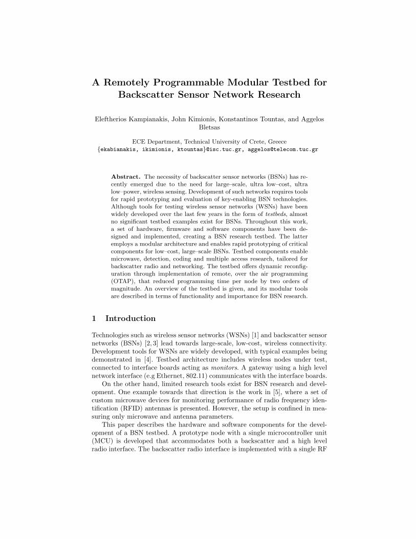
Fig. 1. Left: Hybrid testbed node. Right: Experimentation testbed.
transistor controlled by the MCU. The transistor acts as an antenna load switch,thus achieving backscatter modulation when an incident wave is reflected by theantenna [6]. For the high level control link, a 2.4Ghz radio module is utilized.
The hybrid node developed (Fig. 1-left) acts both as the DUT, which is asemipassive backscatter tag similar to the one presented in [7], and as the unit forremote programming, control and debugging functions. The DUT and monitorfunctions are constructed in software such that they are completely independentto one another.
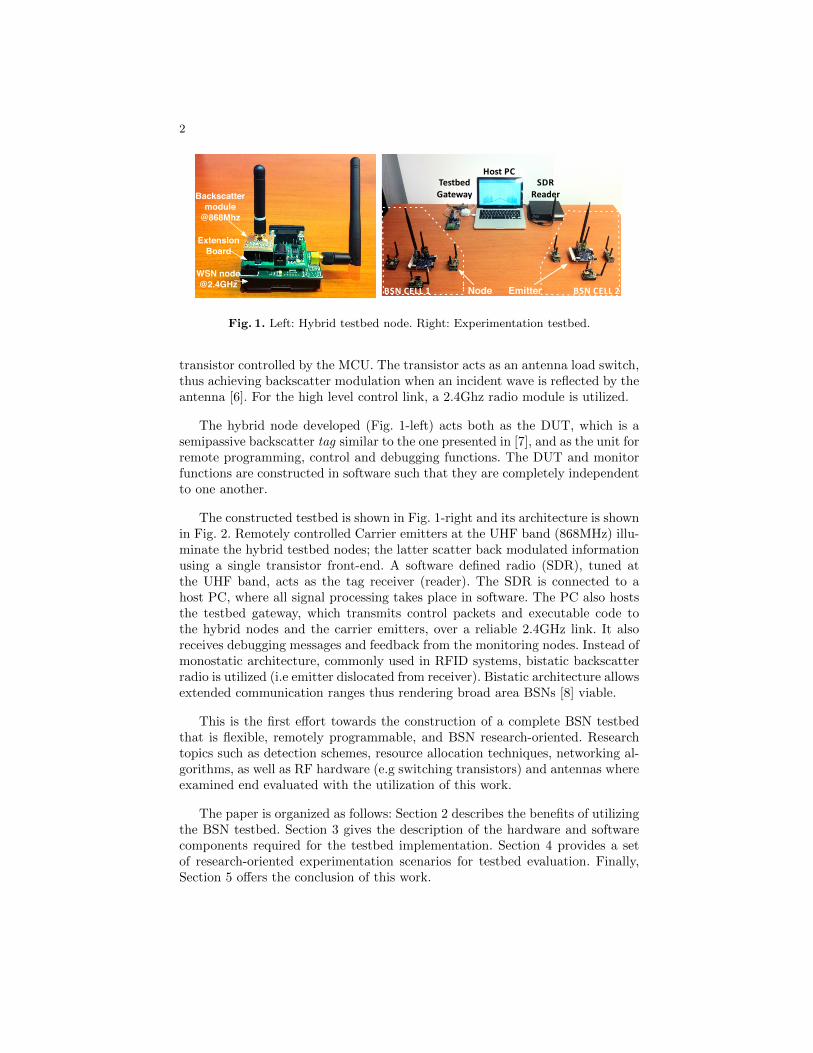
The constructed testbed is shown in Fig. 1-right and its architecture is shownin Fig. 2. Remotely controlled Carrier emitters at the UHF band (868MHz) illu-minate the hybrid testbed nodes; the latter scatter back modulated informationusing a single transistor front-end. A software defined radio (SDR), tuned atthe UHF band, acts as the tag receiver (reader). The SDR is connected to ahost PC, where all signal processing takes place in software. The PC also hoststhe testbed gateway, which transmits control packets and executable code tothe hybrid nodes and the carrier emitters, over a reliable 2.4GHz link. It alsoreceives debugging messages and feedback from the monitoring nodes. Instead ofmonostatic architecture, commonly used in RFID systems, bistatic backscatterradio is utilized (i.e emitter dislocated from receiver). Bistatic architecture allowsextended communication ranges thus rendering broad area BSNs [8] viable.
This is the first effort towards the construction of a complete BSN testbedthat is flexible, remotely programmable, and BSN research-oriented. Researchtopics such as detection schemes, resource allocation techniques, networking al-gorithms, as well as RF hardware (e.g switching transistors) and antennas whereexamined end evaluated with the utilization of this work.
The paper is organized as follows: Section 2 describes the benefits of utilizingthe BSN testbed. Section 3 gives the description of the hardware and softwarecomponents required for the testbed implementation. Section 4 provides a setof research-oriented experimentation scenarios for testbed evaluation. Finally,Section 5 offers the conclusion of this work.
3
Carrier
Emitter
SDR
Reader
Host PC
(DSP & Control)
Testbed
Gateway
Control L
ink
Backscatter Link
Node
Extension
Board
WSN
Node
Backscatter
Module
I/O
2.4GHz
Radio
MCU
2.4GHz
Radio
MCU
868MHz
Radio
MCU
WSN
Node
Carrier
Generator
Fig. 2. Center: Testbed overview. Left: Carrier emitter. Right: hybrid node architectures.
2 Benefits/Features of a BSN Testbed
The utilization of a BSN testbed offers engineers mobility–portability, long rangeremote programmability, debugging and network monitoring, high level of soft-ware and hardware flexibility, dynamic reconfigurability, with relatively low costand most importantly, reduced experimentation time.
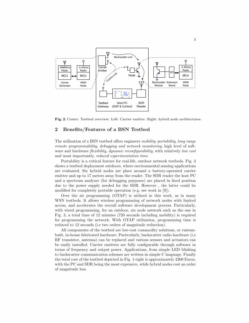
Portability is a critical feature for real-life, outdoor network testbeds. Fig. 3shows a testbed deployment outdoors, where environmental sensing applicationsare evaluated. Six hybrid nodes are place around a battery-operated carrieremitter and up to 17 meters away from the reader. The SDR reader the host PCand a spectrum analyzer (for debugging purposes) are placed in fixed positiondue to the power supply needed for the SDR. However , the latter could bemodified for completely portable operation (e.g. see work in [9]).
Over the air programming (OTAP) is utilized in this work, as in manyWSN testbeds. It allows wireless programming of network nodes with limitedaccess, and accelerates the overall software development process. Particularly,with wired programming, for an outdoor, six node network such as the one inFig. 3, a total time of 12 minutes (720 seconds including mobility) is requiredfor programming the network. With OTAP utilization, programming time isreduced to 12 seconds (i.e two orders of magnitude reduction).
All components of the testbed are low-cost commodity solutions, or custom-built, in-house fabricated hardware. Particularly, backscatter radio hardware (i.eRF transistor, antenna) can be replaced and various sensors and actuators canbe easily installed. Carrier emitters are fully configurable through software interms of frequency and output power. Applications, from simple LED blinkingto backscatter communication schemes are written in simple C language. Finallythe total cost of the testbed depicted in Fig. 1-right is approximately 2300 Euros,with the PC and SDR being the most expensive, while hybrid nodes cost an orderof magnitude less.
4
TAG 6
TAG 5
TAG 4 TAG 3
TAG 2
TAG 1
Carrier Emitter13m
17m
15m16m
5m8m
8m
Receiver
Fig. 3. Remotely programmable testbed and hybrid node, outdoor deployment.
3 Testbed Implementation
Hardware. The core testbed module is a hybrid node.Having the classic WSN testbed in mind a WSN node was utilized to act as
the monitoring device and as the DUT. A module equipped with a backscatterRF front-end is connected to the interface board of the WSN node [10]. The nodeexchanges control data with the gateway using the embedded 2.4Ghz RF moduleand backscatter communication is achieved with the backscatter module.
The backscatter module is equipped with a RF transistor and an SMA an-tenna connector. The transistor’s base is driven by an MCU pin, while the othertwo are connected to the antenna terminals. When the MCU drives the basepin on high level or low level, the transistor acts as a short or an open circuit,respectively. This allows switching between two antenna reflection coefficients,therefore enabling backscatter modulation [6, 11]. Fig. 1-left depicts the imple-mented node and Fig. 2 (right) depicts node architecture.
To enable backscatter communication, low-cost, battery-operated RF carrieremitters are utilized. These devices, in the form of monolithic MCU–radio, areprogrammable signal generators. These modules are connected with the WSNnodes via the reliable 2.4GHz link and as result, there is full control over thewhole network. Several of the devices may exist on a test field, promoting exper-imentation with bistatic/multistatic backscatter links. These are less-exploredbackscatter architectures, with emerging research interest [8, 12,13].
For the reception of backscatter signals, a commodity software defined radio(SDR) is used, while the processing takes place on a host PC, using MATLAB.This offers the flexibility to study communication schemes in depth. Since fullcontrol over the physical layer is required, no commercial “black box” devicesare utilized.
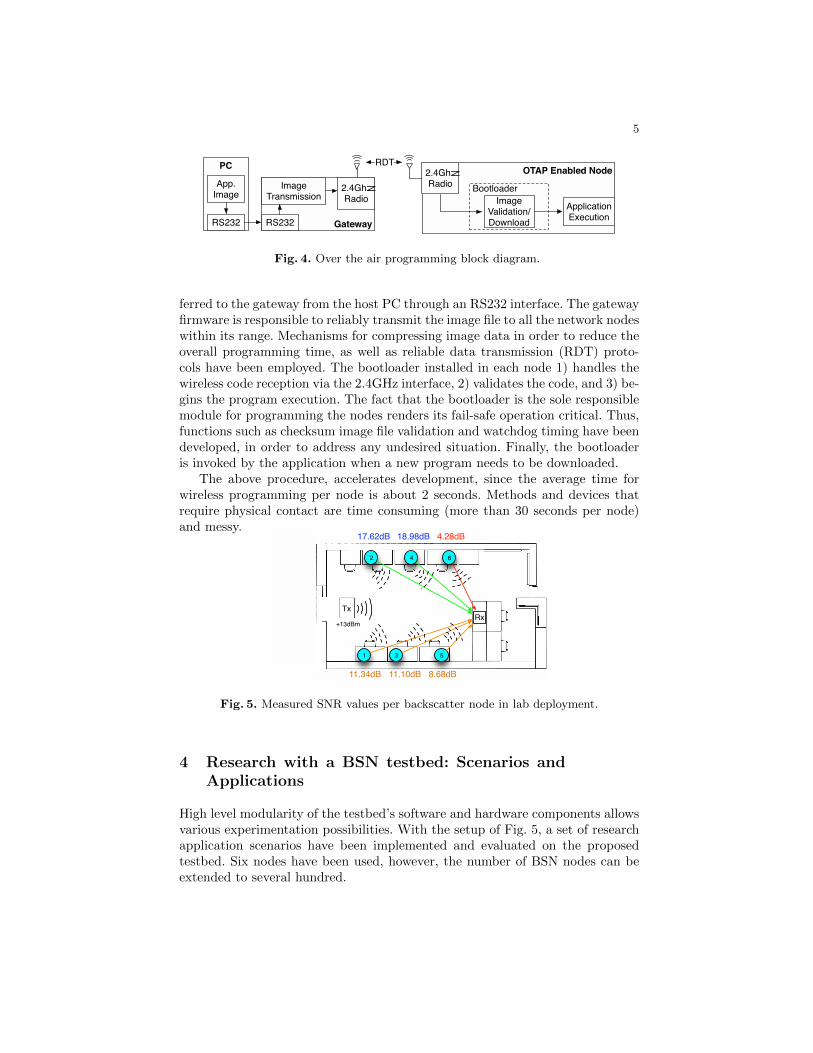
Software. The major software component of this work implements remotetestbed programmability. The testbed’s software system architecture is depictedin Fig. 4 and mainly consists of three parts: the bootloader, the gateway firmware,and the application. The application may be any type of code that can be ex-ecuted by the node platform. Initially, the user application image file is trans-
5
PC
App.Image
RS232
RDT
RS232
2.4GhzRadio
OTAP Enabled Node2.4GhzRadio
ApplicationExecution
Bootloader
Image Validation/DownloadGateway
Image Transmission
Fig. 4. Over the air programming block diagram.
ferred to the gateway from the host PC through an RS232 interface. The gatewayfirmware is responsible to reliably transmit the image file to all the network nodeswithin its range. Mechanisms for compressing image data in order to reduce theoverall programming time, as well as reliable data transmission (RDT) proto-cols have been employed. The bootloader installed in each node 1) handles thewireless code reception via the 2.4GHz interface, 2) validates the code, and 3) be-gins the program execution. The fact that the bootloader is the sole responsiblemodule for programming the nodes renders its fail-safe operation critical. Thus,functions such as checksum image file validation and watchdog timing have beendeveloped, in order to address any undesired situation. Finally, the bootloaderis invoked by the application when a new program needs to be downloaded.
The above procedure, accelerates development, since the average time forwireless programming per node is about 2 seconds. Methods and devices thatrequire physical contact are time consuming (more than 30 seconds per node)and messy.
11.34dB 11.10dB 8.68dB
4.28dB18.98dB17.62dB
+13dBm
2
1
4
3
6
5
Tx
Rx
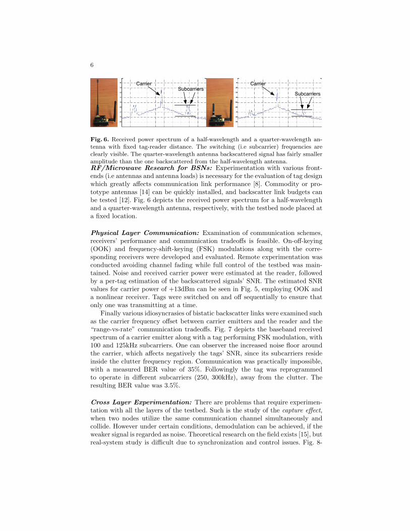
Fig. 5. Measured SNR values per backscatter node in lab deployment.
4 Research with a BSN testbed: Scenarios andApplications
High level modularity of the testbed’s software and hardware components allowsvarious experimentation possibilities. With the setup of Fig. 5, a set of researchapplication scenarios have been implemented and evaluated on the proposedtestbed. Six nodes have been used, however, the number of BSN nodes can beextended to several hundred.
6
Carrier
Subcarriers
Carrier
Subcarriers
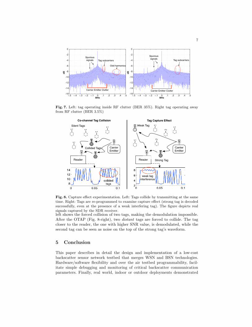
Fig. 6. Received power spectrum of a half-wavelength and a quarter-wavelength an-tenna with fixed tag-reader distance. The switching (i.e subcarrier) frequencies areclearly visible. The quarter-wavelength antenna backscattered signal has fairly smalleramplitude than the one backscattered from the half-wavelength antenna.RF/Microwave Research for BSNs: Experimentation with various front-ends (i.e antennas and antenna loads) is necessary for the evaluation of tag designwhich greatly affects communication link performance [8]. Commodity or pro-totype antennas [14] can be quickly installed, and backscatter link budgets canbe tested [12]. Fig. 6 depicts the received power spectrum for a half-wavelengthand a quarter-wavelength antenna, respectively, with the testbed node placed ata fixed location.
Physical Layer Communication: Examination of communication schemes,receivers’ performance and communication tradeoffs is feasible. On-off-keying(OOK) and frequency-shift-keying (FSK) modulations along with the corre-sponding receivers were developed and evaluated. Remote experimentation wasconducted avoiding channel fading while full control of the testbed was main-tained. Noise and received carrier power were estimated at the reader, followedby a per-tag estimation of the backscattered signals’ SNR. The estimated SNRvalues for carrier power of +13dBm can be seen in Fig. 5, employing OOK anda nonlinear receiver. Tags were switched on and off sequentially to ensure thatonly one was transmitting at a time.
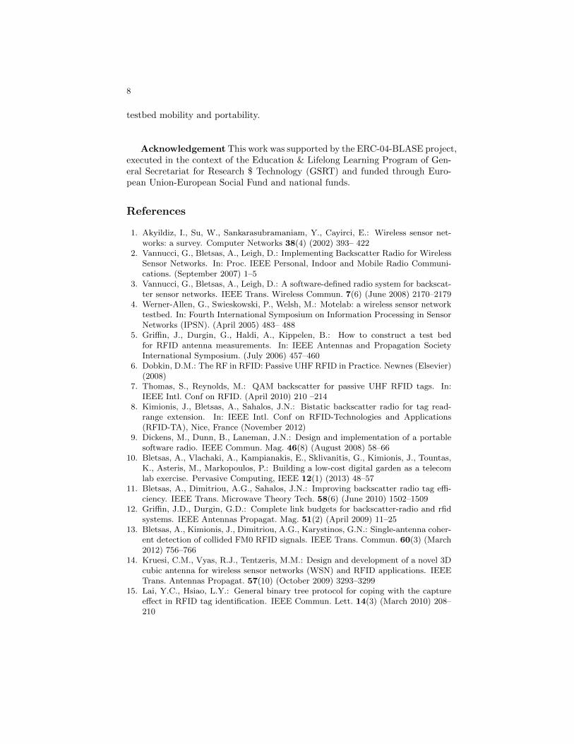
Finally various idiosyncrasies of bistatic backscatter links were examined suchas the carrier frequency offset between carrier emitters and the reader and the“range-vs-rate” communication tradeoffs. Fig. 7 depicts the baseband receivedspectrum of a carrier emitter along with a tag performing FSK modulation, with100 and 125kHz subcarriers. One can observer the increased noise floor aroundthe carrier, which affects negatively the tags’ SNR, since its subcarriers resideinside the clutter frequency region. Communication was practically impossible,with a measured BER value of 35%. Followingly the tag was reprogrammedto operate in different subcarriers (250, 300kHz), away from the clutter. Theresulting BER value was 3.5%.
Cross Layer Experimentation: There are problems that require experimen-tation with all the layers of the testbed. Such is the study of the capture effect,when two nodes utilize the same communication channel simultaneously andcollide. However under certain conditions, demodulation can be achieved, if theweaker signal is regarded as noise. Theoretical research on the field exists [15], butreal-system study is difficult due to synchronization and control issues. Fig. 8-
7
−.5 −.4 −.3 −.2 −.1 0 .1 .2 .3 .4 .5-16
-14
-12
-10
-8
-6
-4
-2
0
MHz
dB
−.5 −.4 −.3 −.2 −.1 0 .1 .2 .3 .4 .5-16
-14
-12
-10
-8
-6
-4
-2
0
MHz
dB
Fig. 7. Left: tag operating inside RF clutter (BER 35%). Right tag operating awayfrom RF clutter (BER 3.5%)
Reader
CarrierEmitter
Collided Tags
Silent Tags
Co-channel Tag Collision
collidedtags
Reader
CarrierEmitter
Strong Tag
Weak Tag
Tag Capture Effect
weak taginterference
Fig. 8. Capture effect experimentation. Left: Tags collide by transmitting at the sametime. Right: Tags are re-programmed to examine capture effect (strong tag is decodedsuccessfully, even at the presence of a weak interfering tag). The figure depicts realsignals captured by the SDR receiver.left shows the forced collision of two tags, making the demodulation impossible.After the OTAP (Fig. 8-right), two distant tags are forced to collide. The tagcloser to the reader, the one with higher SNR value, is demodulated, while thesecond tag can be seen as noise on the top of the strong tag’s waveform.
5 Conclusion
This paper describes in detail the design and implementation of a low-costbackscatter sensor network testbed that merges WSN and BSN technologies.Hardware/software flexibility and over the air testbed programmability, facil-itate simple debugging and monitoring of critical backscatter communicationparameters. Finally, real world, indoor or outdoor deployments demonstrated
8
testbed mobility and portability.
Acknowledgement This work was supported by the ERC-04-BLASE project,executed in the context of the Education & Lifelong Learning Program of Gen-eral Secretariat for Research $ Technology (GSRT) and funded through Euro-pean Union-European Social Fund and national funds.
References
1. Akyildiz, I., Su, W., Sankarasubramaniam, Y., Cayirci, E.: Wireless sensor net-works: a survey. Computer Networks 38(4) (2002) 393– 422
2. Vannucci, G., Bletsas, A., Leigh, D.: Implementing Backscatter Radio for WirelessSensor Networks. In: Proc. IEEE Personal, Indoor and Mobile Radio Communi-cations. (September 2007) 1–5
3. Vannucci, G., Bletsas, A., Leigh, D.: A software-defined radio system for backscat-ter sensor networks. IEEE Trans. Wireless Commun. 7(6) (June 2008) 2170–2179
4. Werner-Allen, G., Swieskowski, P., Welsh, M.: Motelab: a wireless sensor networktestbed. In: Fourth International Symposium on Information Processing in SensorNetworks (IPSN). (April 2005) 483– 488
5. Griffin, J., Durgin, G., Haldi, A., Kippelen, B.: How to construct a test bedfor RFID antenna measurements. In: IEEE Antennas and Propagation SocietyInternational Symposium. (July 2006) 457–460
6. Dobkin, D.M.: The RF in RFID: Passive UHF RFID in Practice. Newnes (Elsevier)(2008)
7. Thomas, S., Reynolds, M.: QAM backscatter for passive UHF RFID tags. In:IEEE Intl. Conf on RFID. (April 2010) 210 –214
8. Kimionis, J., Bletsas, A., Sahalos, J.N.: Bistatic backscatter radio for tag read-range extension. In: IEEE Intl. Conf on RFID-Technologies and Applications(RFID-TA), Nice, France (November 2012)
9. Dickens, M., Dunn, B., Laneman, J.N.: Design and implementation of a portablesoftware radio. IEEE Commun. Mag. 46(8) (August 2008) 58–66
10. Bletsas, A., Vlachaki, A., Kampianakis, E., Sklivanitis, G., Kimionis, J., Tountas,K., Asteris, M., Markopoulos, P.: Building a low-cost digital garden as a telecomlab exercise. Pervasive Computing, IEEE 12(1) (2013) 48–57
11. Bletsas, A., Dimitriou, A.G., Sahalos, J.N.: Improving backscatter radio tag effi-ciency. IEEE Trans. Microwave Theory Tech. 58(6) (June 2010) 1502–1509
12. Griffin, J.D., Durgin, G.D.: Complete link budgets for backscatter-radio and rfidsystems. IEEE Antennas Propagat. Mag. 51(2) (April 2009) 11–25
13. Bletsas, A., Kimionis, J., Dimitriou, A.G., Karystinos, G.N.: Single-antenna coher-ent detection of collided FM0 RFID signals. IEEE Trans. Commun. 60(3) (March2012) 756–766
14. Kruesi, C.M., Vyas, R.J., Tentzeris, M.M.: Design and development of a novel 3Dcubic antenna for wireless sensor networks (WSN) and RFID applications. IEEETrans. Antennas Propagat. 57(10) (October 2009) 3293–3299
15. Lai, Y.C., Hsiao, L.Y.: General binary tree protocol for coping with the captureeffect in RFID tag identification. IEEE Commun. Lett. 14(3) (March 2010) 208–210
![Towards Adaptive Benthic Habitat Mapping · For marine habitat-modelling, the remotely-sensed data used is typically bathymetry and backscatter, collected from ship-borne sonars [7]](https://img.pdfslide.us/doc/110x75/606bc3c181226b50f60f5caf/towards-adaptive-benthic-habitat-mapping-for-marine-habitat-modelling-the-remotely-sensed.jpg)


![15 Sediment Gages - USGS · 0.2707 c,S372 Velccty and backscatter seres C] Depth-averaøed streamwise vebcfy RMS Curr.tive u at depths backscatter Depth-averaged backscatter Contour](https://img.pdfslide.us/doc/110x75/5fd8133cbc6723794903cbd2/15-sediment-gages-usgs-02707-cs372-velccty-and-backscatter-seres-c-depth-averaed.jpg)