Embed Size (px)
Citation preview
The Fundamentals of Backscatter Radio and RFID Systems
Joshua [email protected]
Disney Research, Pittsburgh4615 Forbes Ave.
Pittsburgh, PA 15213

About Myself• Post-doctoral Associate with Disney Research,
Pittsburgh– Work closely with researchers at Carnegie Mellon
University • Professor Dan Stancil
• Darmindra Arumugam, PhD student
Copyright 2009 2
Prof. Stancil Darmindra

About Myself• BS in Engineering from LeTourneau University in 2003.
• MS in Electrical and Computer Engineering (ECE) from Georgia Tech in 2005.
• PhD in ECE from Georgia Tech in January, 2009.
• The Propagation Group– Founded and directed by Professor Gregory Durgin
– http://www.propagation.gatech.edu
Copyright 2009 3
Prof. Durgin
Part I1. Introduction to Backscatter Radio and RFID
2. A Short History of RFID and Backscatter Radio Devices
3. The Fundamentals of Backscatter RFID Propagation
4. Radio Link Budgets for Backscatter RFID
5. Typical UHF RFID Performance Shown Through Example
6. Q & A
7. Break
Copyright 2009 4
Part II8. RFID Modulation and Coding
9. RFID System Communication Protocols
10. Spread Spectrum Backscatter RFID
11. Backscatter Radio and RFID Systems Using Multiple Antennas
12. Backscatter RFID: A Look to the Future
13. Q & A
Copyright 2009 5
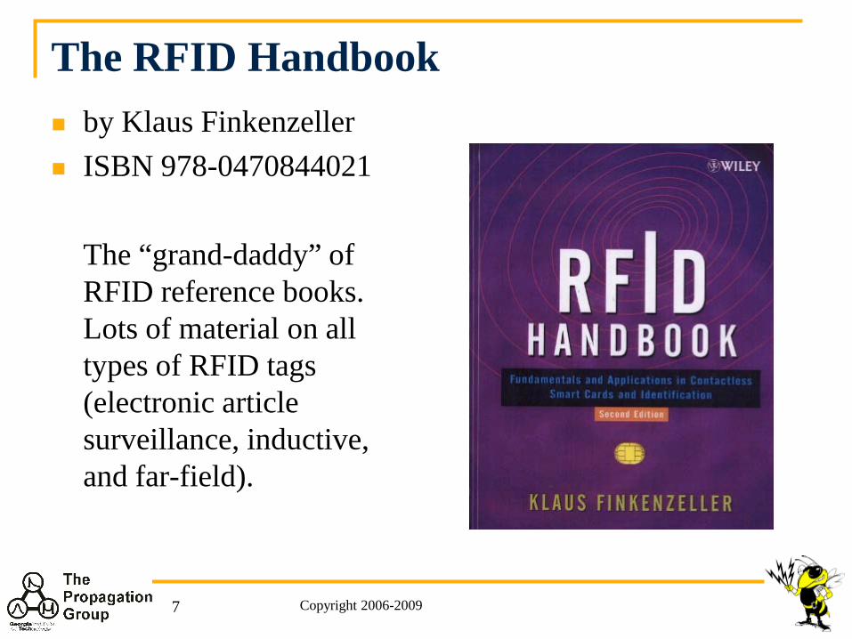
The RFID Handbook by Klaus Finkenzeller ISBN 978-0470844021
The “grand-daddy” of RFID reference books. Lots of material on all types of RFID tags (electronic article surveillance, inductive, and far-field).
Copyright 2006-20097
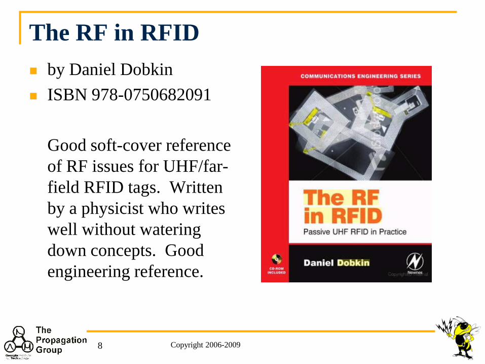
The RF in RFID by Daniel Dobkin ISBN 978-0750682091
Good soft-cover reference of RF issues for UHF/far-field RFID tags. Written by a physicist who writes well without watering down concepts. Good engineering reference.
Copyright 2006-20098
INTRODUCTION TO BACKSCATTER RADIO AND RFID
Copyright 2009 9
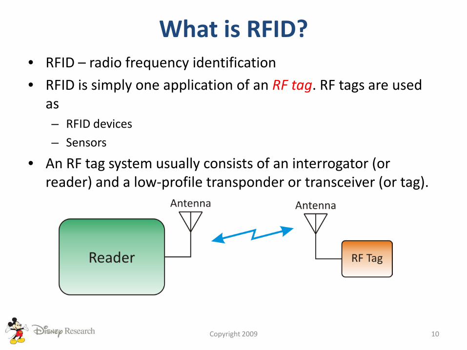
What is RFID?• RFID – radio frequency identification
• RFID is simply one application of an RF tag. RF tags are used as– RFID devices
– Sensors
• An RF tag system usually consists of an interrogator (or reader) and a low-profile transponder or transceiver (or tag).
Copyright 2009 10
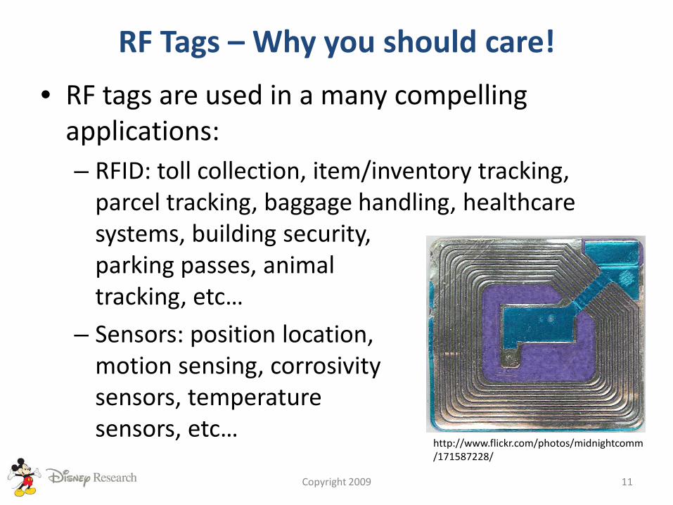
RF Tags – Why you should care!
• RF tags are used in a many compelling applications:– RFID: toll collection, item/inventory tracking,
parcel tracking, baggage handling, healthcare systems, building security, parking passes, animal tracking, etc…
– Sensors: position location,motion sensing, corrosivitysensors, temperature sensors, etc…
Copyright 2009 11
http://www.flickr.com/photos/midnightcomm/171587228/
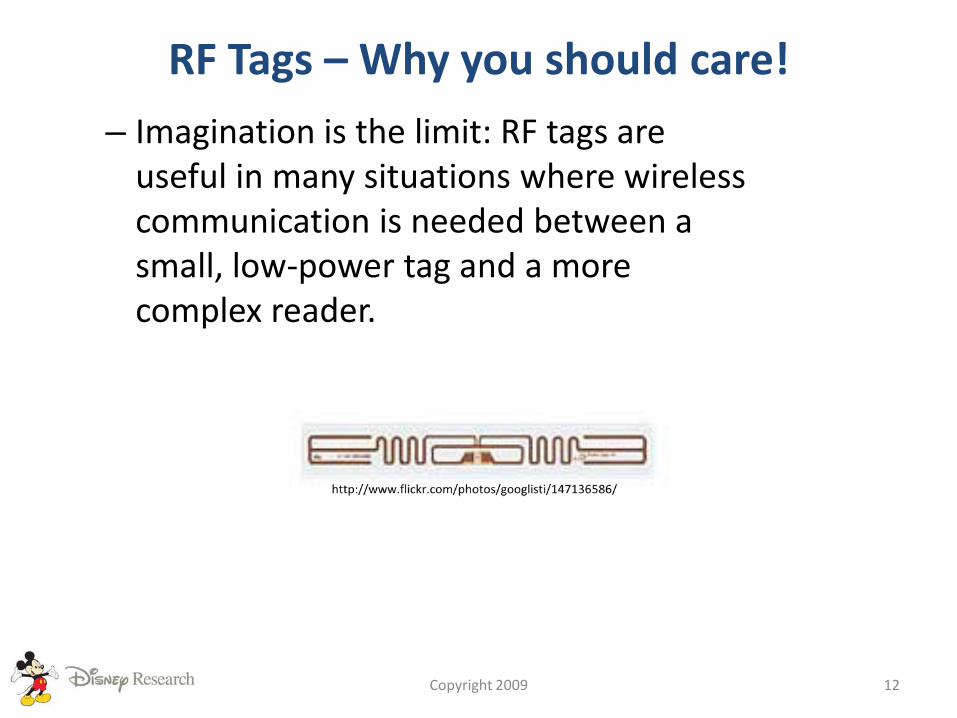
RF Tags – Why you should care!
– Imagination is the limit: RF tags are useful in many situations where wireless communication is needed between a small, low-power tag and a more complex reader.
Copyright 2009 12
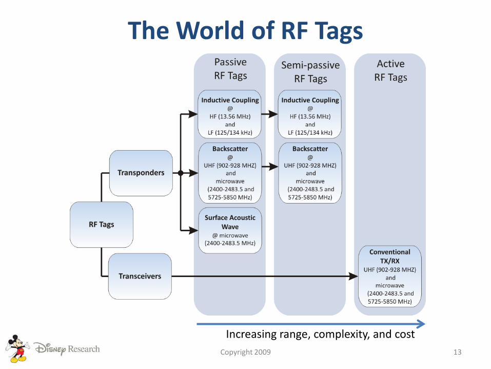
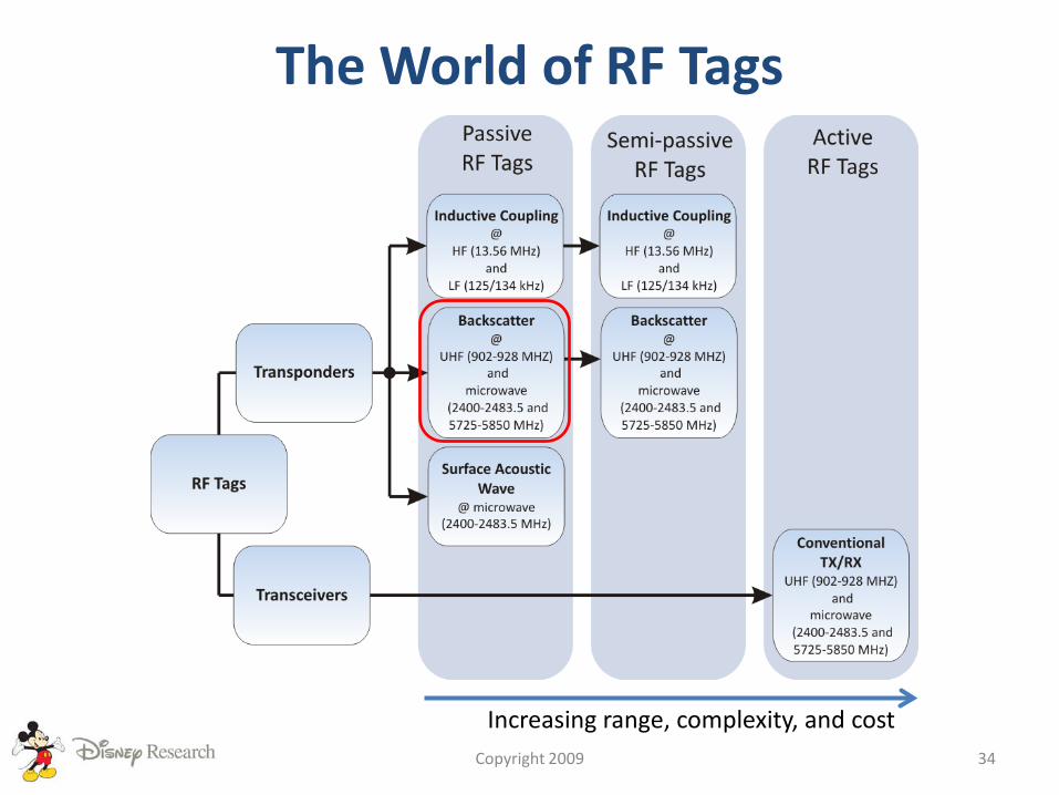
The World of RF Tags
Copyright 2009 13
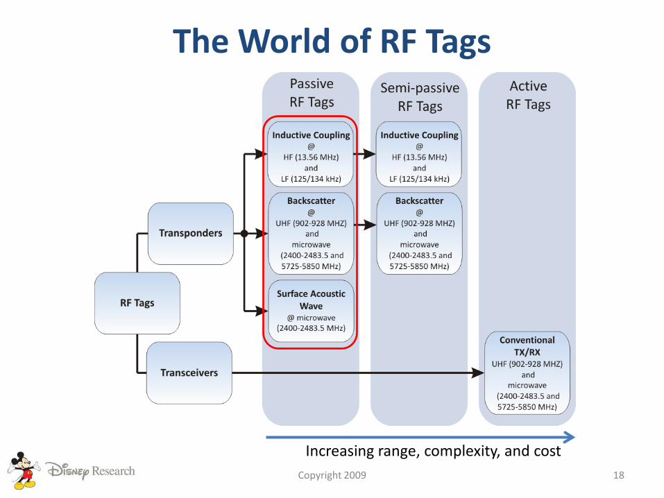
Increasing range, complexity, and cost
The World of RF Tags
Copyright 2009 14
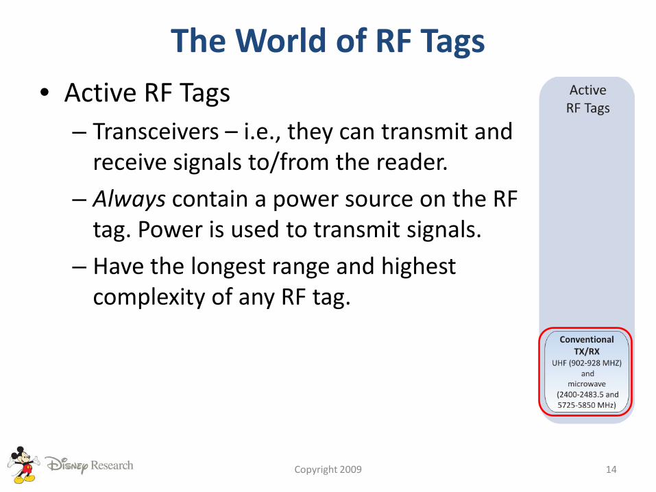
• Active RF Tags– Transceivers – i.e., they can transmit and
receive signals to/from the reader.
– Always contain a power source on the RF tag. Power is used to transmit signals.
– Have the longest range and highest complexity of any RF tag.
The World of RF Tags
Copyright 2009 15
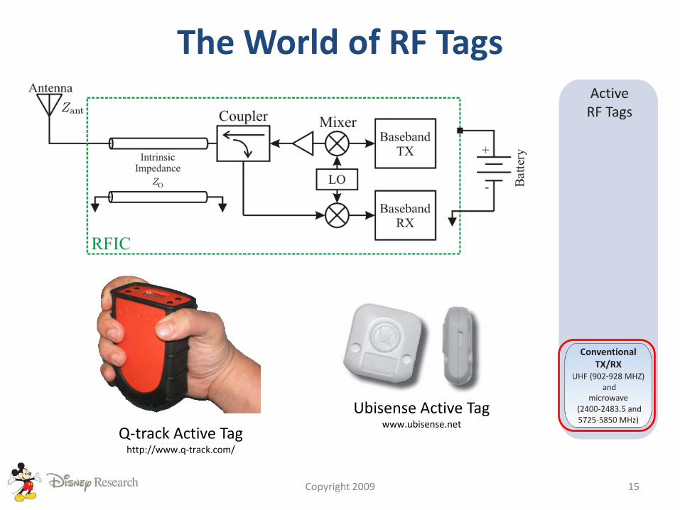
Q-track Active Taghttp://www.q-track.com/
Ubisense Active Tagwww.ubisense.net

The World of RF Tags
Copyright 2009 16
• Semi-passive RF Tags– Transponders – they can receive signals
from the reader, but do not transmit signals to the reader.
– Instead, a signal is provided by the reader and altered by the RF tag for wireless communication.
– Always contain a power source on the RF tag. Power is not used to transmit signals.
– Have the second longest range of all RF tags.
The World of RF Tags
Copyright 2009 17
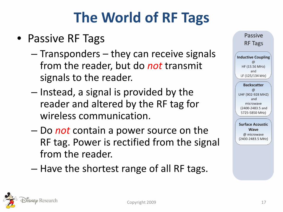
• Passive RF Tags– Transponders – they can receive signals
from the reader, but do not transmit signals to the reader.
– Instead, a signal is provided by the reader and altered by the RF tag for wireless communication.
– Do not contain a power source on the RF tag. Power is rectified from the signal from the reader.
– Have the shortest range of all RF tags.
The World of RF Tags
Copyright 2009 18
Increasing range, complexity, and cost
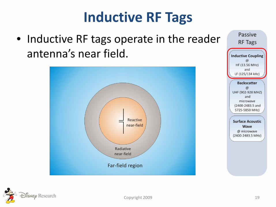
Inductive RF Tags
Copyright 2009 19
• Inductive RF tags operate in the reader antenna’s near field.
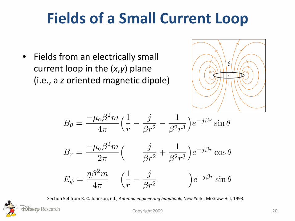
Fields of a Small Current Loop
Copyright 2009 20
• Fields from an electrically smallcurrent loop in the (x,y) plane (i.e., a z oriented magnetic dipole)
Section 5.4 from R. C. Johnson, ed., Antenna engineering handbook, New York : McGraw-Hill, 1993.
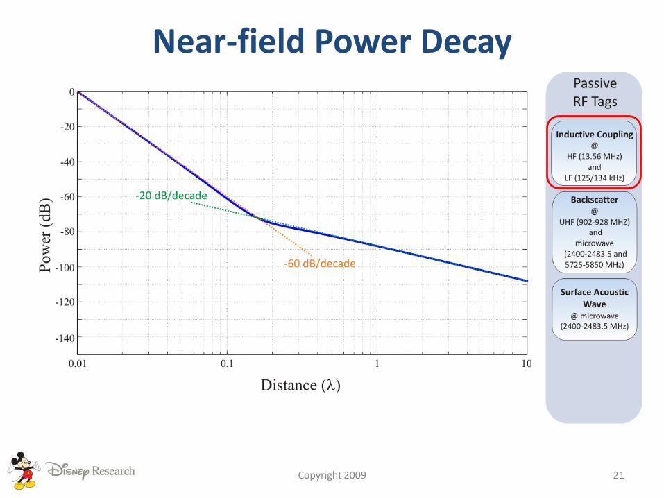
Near-field Power Decay
Copyright 2009 21
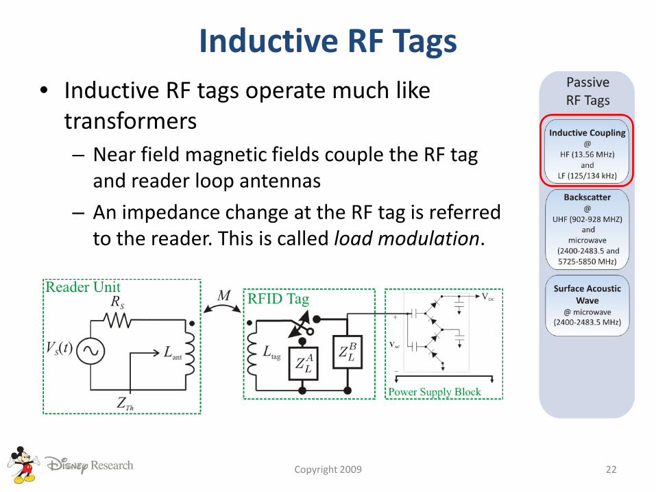
Inductive RF Tags• Inductive RF tags operate much like
transformers– Near field magnetic fields couple the RF tag
and reader loop antennas
– An impedance change at the RF tag is referred to the reader. This is called load modulation.
Copyright 2009 22
Charge Pumps
Copyright 2009 23
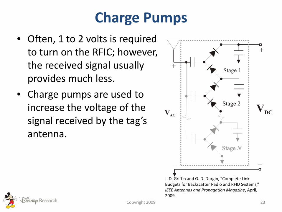
• Often, 1 to 2 volts is required to turn on the RFIC; however, the received signal usually provides much less.
• Charge pumps are used to increase the voltage of the signal received by the tag’s antenna.
J. D. Griffin and G. D. Durgin, “Complete Link Budgets for Backscatter Radio and RFID Systems,” IEEE Antennas and Propagation Magazine, April, 2009.
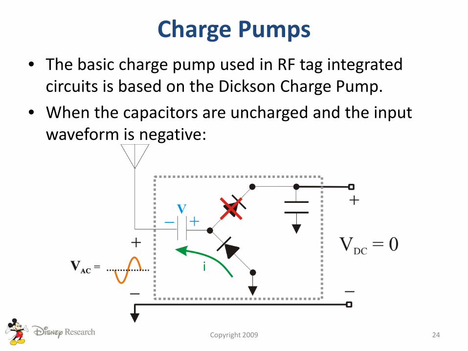
Charge Pumps• The basic charge pump used in RF tag integrated
circuits is based on the Dickson Charge Pump.
• When the capacitors are uncharged and the input waveform is negative:
Copyright 2009 24

Charge Pumps• When the waveform swings positive:
Copyright 2009 25

Charge Pumps• Once the capacitors have charges and the
input waveform is positive:
Copyright 2009 26
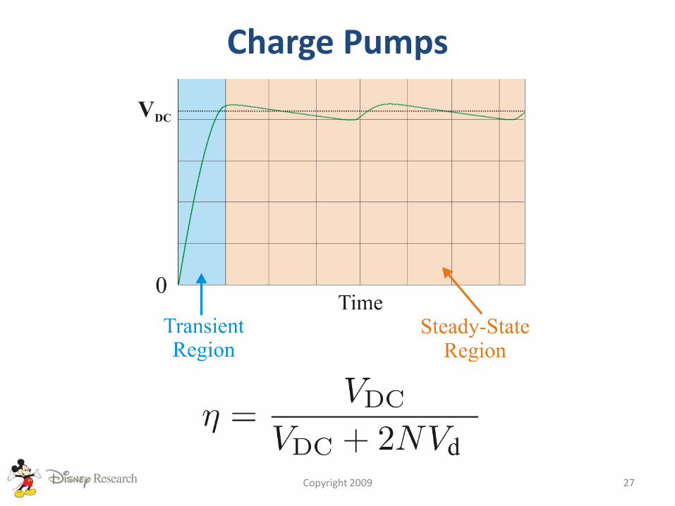
Charge Pumps
Copyright 2009 27
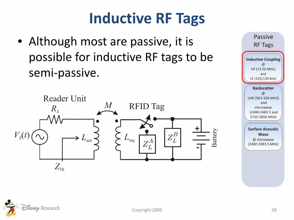
Inductive RF Tags• Although most are passive, it is
possible for inductive RF tags to be semi-passive.
Copyright 2009 28
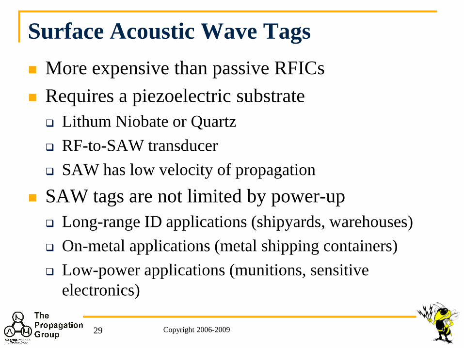
Surface Acoustic Wave Tags More expensive than passive RFICs Requires a piezoelectric substrate Lithum Niobate or Quartz RF-to-SAW transducer SAW has low velocity of propagation
SAW tags are not limited by power-up Long-range ID applications (shipyards, warehouses) On-metal applications (metal shipping containers) Low-power applications (munitions, sensitive
electronics)
Copyright 2006-200929
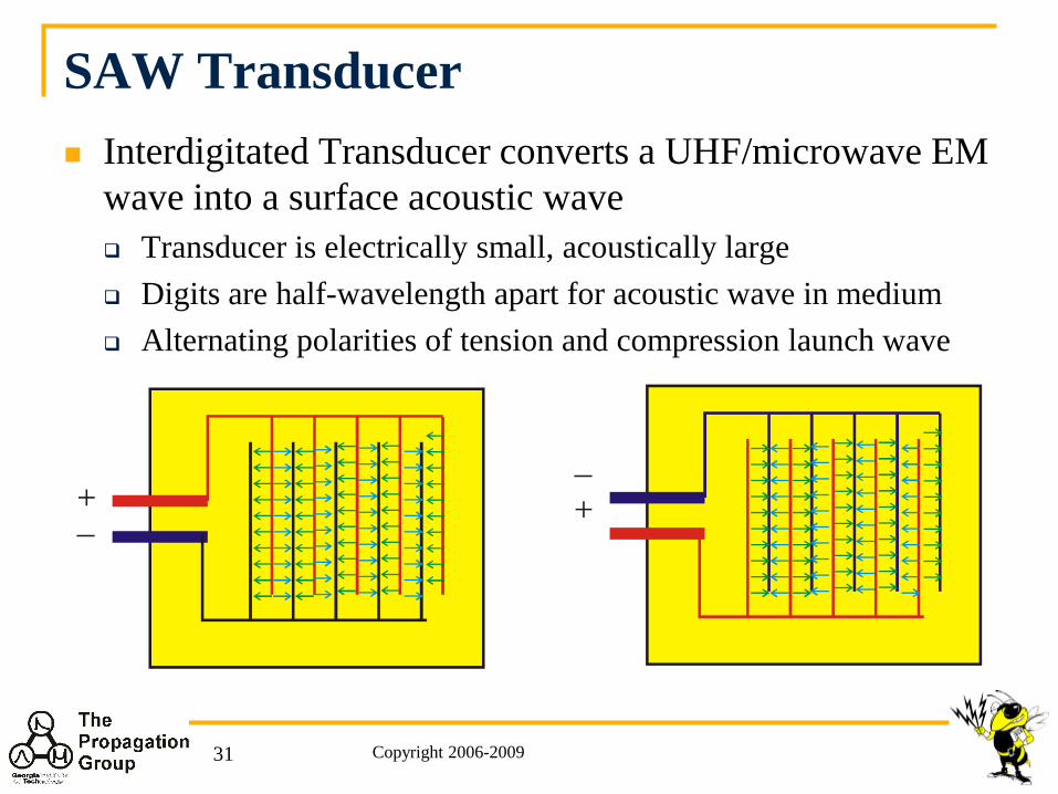
SAW Transducer Interdigitated Transducer converts a UHF/microwave EM
wave into a surface acoustic wave Transducer is electrically small, acoustically large Digits are half-wavelength apart for acoustic wave in medium Alternating polarities of tension and compression launch wave
+ +−
−
Copyright 2006-200931
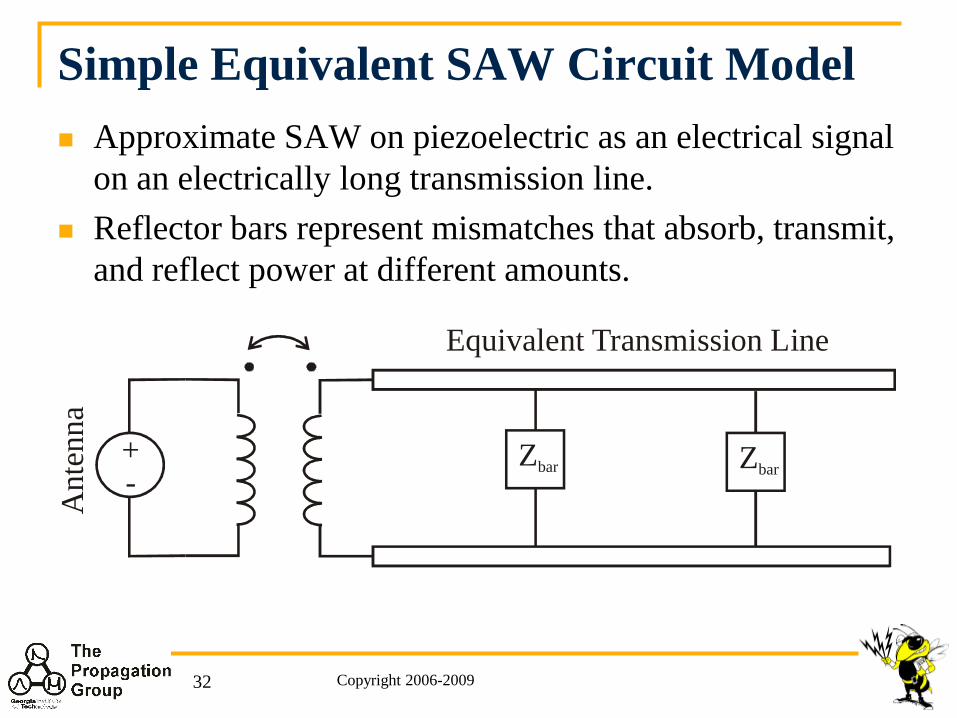
Simple Equivalent SAW Circuit Model Approximate SAW on piezoelectric as an electrical signal
on an electrically long transmission line. Reflector bars represent mismatches that absorb, transmit,
and reflect power at different amounts.
Zbar Zbar
Equivalent Transmission Line
Ant
enna
+-
Copyright 2006-200932
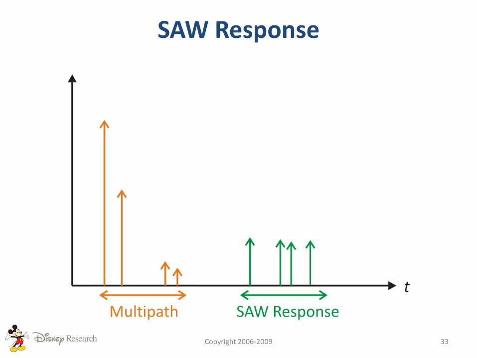
SAW Response
Copyright 2006-2009 33
The World of RF Tags
Copyright 2009 34
Increasing range, complexity, and cost
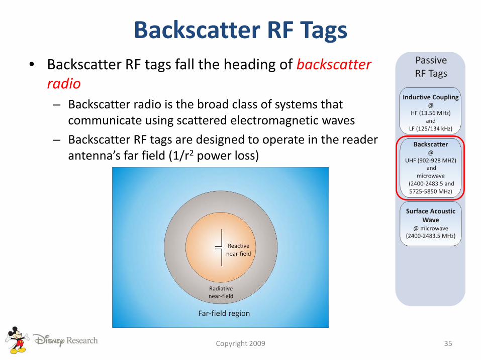
Backscatter RF Tags• Backscatter RF tags fall the heading of backscatter
radio– Backscatter radio is the broad class of systems that
communicate using scattered electromagnetic waves
– Backscatter RF tags are designed to operate in the reader antenna’s far field (1/r2 power loss)
Copyright 2009 35
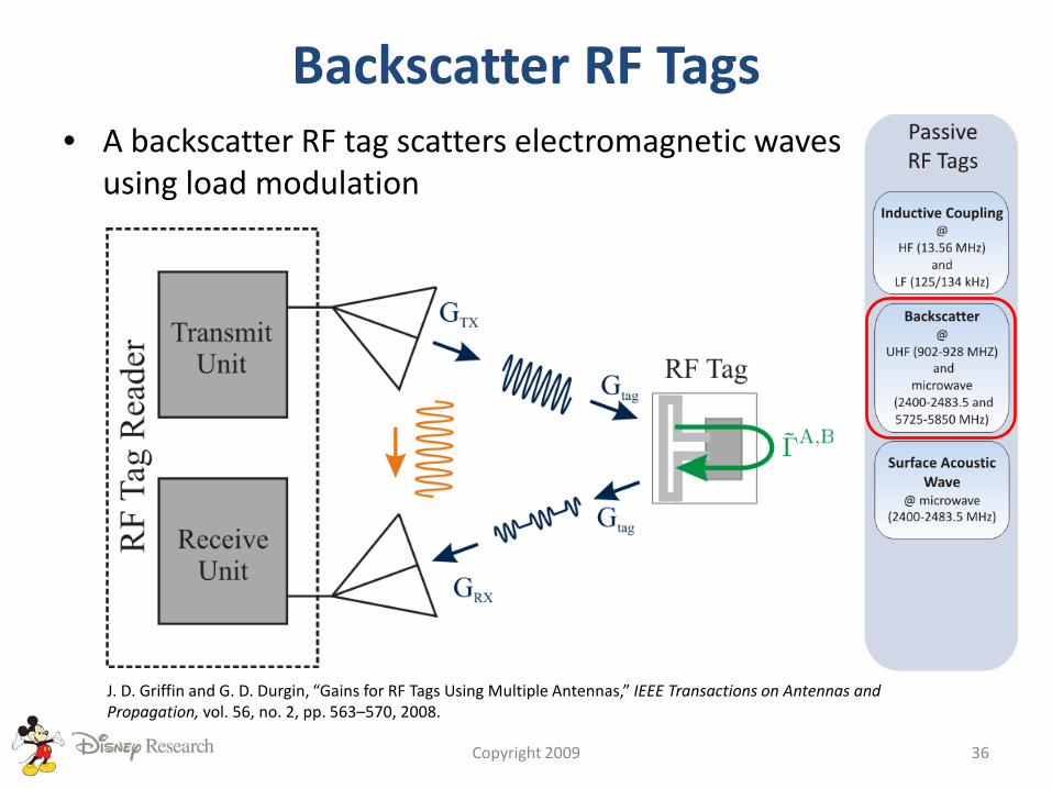
Backscatter RF Tags• A backscatter RF tag scatters electromagnetic waves
using load modulation
Copyright 2009 36
J. D. Griffin and G. D. Durgin, “Gains for RF Tags Using Multiple Antennas,” IEEE Transactions on Antennas and Propagation, vol. 56, no. 2, pp. 563–570, 2008.
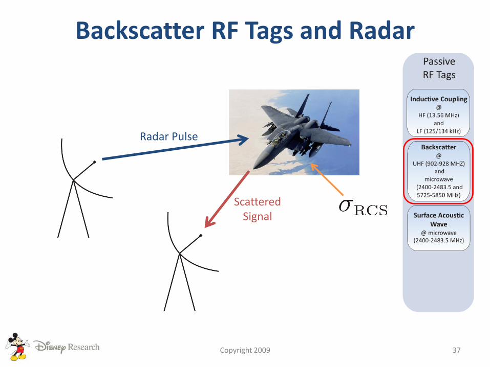
Backscatter RF Tags and Radar
Copyright 2009 37
Radar Pulse
ScatteredSignal
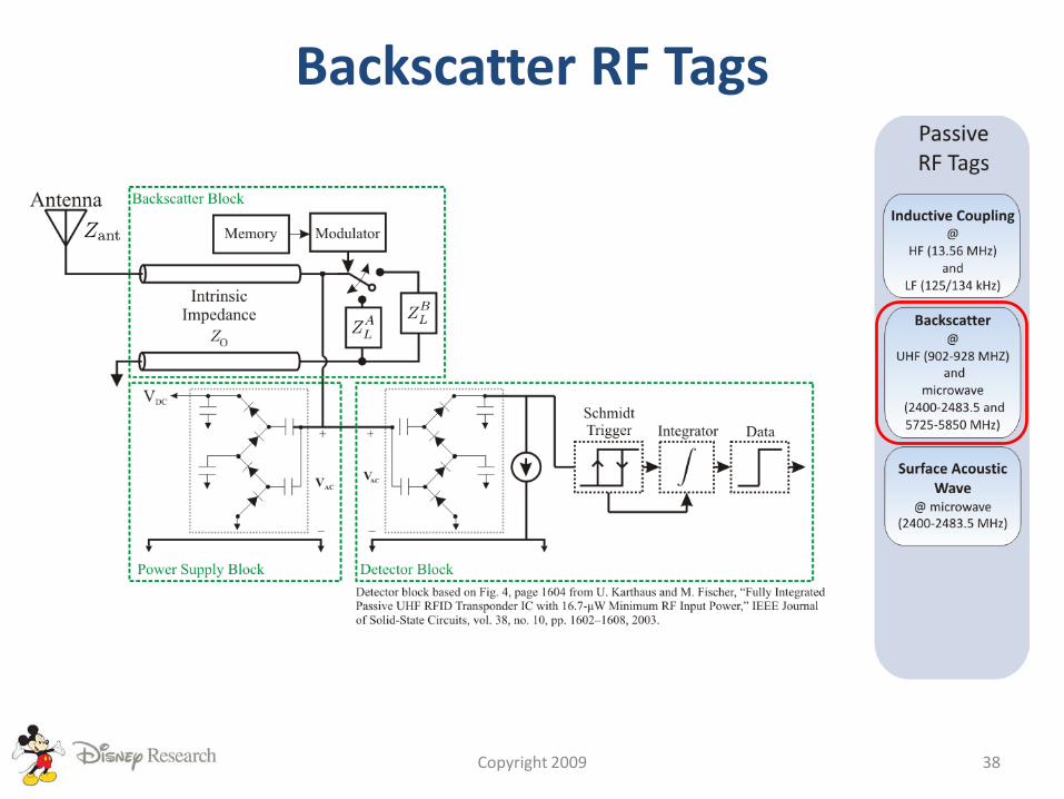
Backscatter RF Tags
Copyright 2009 38

Backscatter Reflection Coefficient
Copyright 2009 39
J. D. Griffin and G. D. Durgin, “Complete Link Budgets for Backscatter Radio and RFID Systems,” IEEE Antennas and Propagation Magazine, April, 2009.
Backscatter RF Tag Readers• Readers come in two flavors:
– Monostatic
– Bistatic
• Unique Challenges of Backscatter Readers– Two signals are received
• Self-interference
• Modulated backscatter signal
– High power and dynamic range
Copyright 2009 40

Understanding the Backscattered Signal
Copyright 2009 41
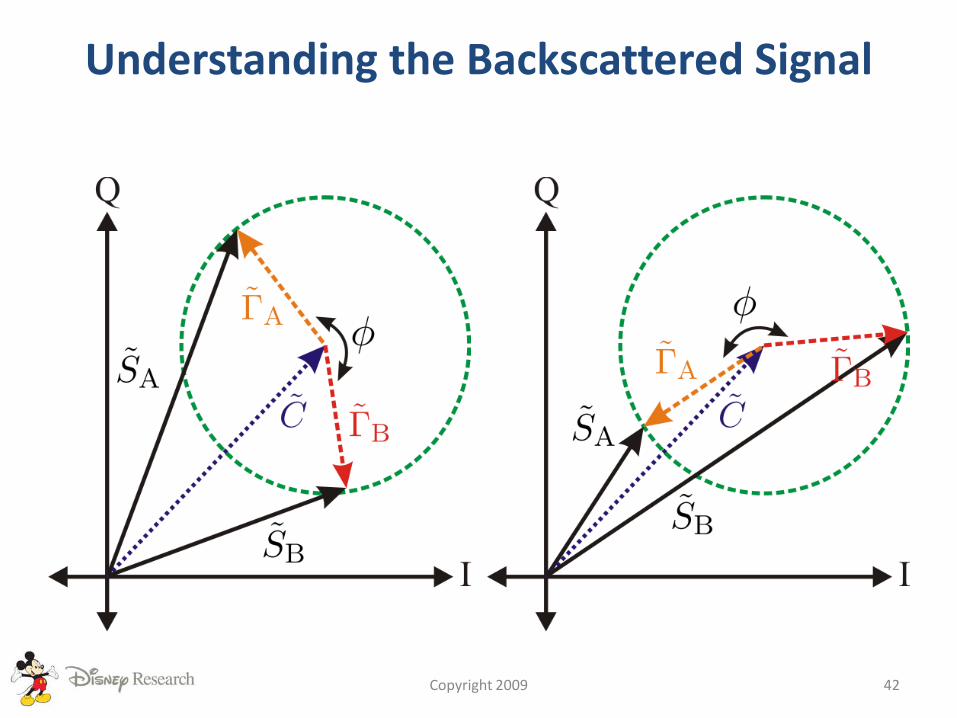
Understanding the Backscattered Signal
Copyright 2009 42
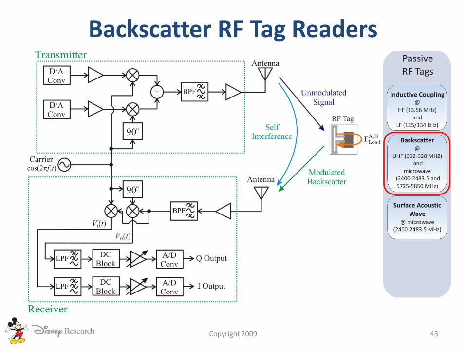
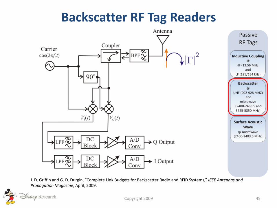
Backscatter RF Tag Readers
Copyright 2009 43
Solutions for Self-Interference• Direct-conversion receiver with baseband DC
blocking capacitors.
• Active carrier cancellation at the receiver input.
• Use cross-polar reader transmitter and receiver antennas.
Copyright 2009 44
Backscatter RF Tag Readers
Copyright 2009 45
J. D. Griffin and G. D. Durgin, “Complete Link Budgets for Backscatter Radio and RFID Systems,” IEEE Antennas and Propagation Magazine, April, 2009.

A SHORT HISTORY OF RFID AND BACKSCATTER RADIO DEVICES
Copyright 2009 46
Then…• Backscatter RF tags have their origins in radar
– Radar was developed during WWII
– There was a need to identify the aircraft. The solution was the Identify Friend or Foe (IFF) system.
• Most of these systems were active transmitter/receiver systems.
• Groundbreaking paper published in 1948:H. Stockman, “Communication by Means of Reflected Power,” Proceedings of the I.R.E., vol. 36, no. 10, pp. 1196—1204, 1948.
Copyright 2009 47
Then…• 1940s and 1950s – the foundation for RFID laid• 1960s – development of electronic article surveillance
(EAS) systems– 1-bit tags
• 1970s – development work• 1980s – RFID began finding mainstream commercial
applications, in particular electronic toll collection. UHF and microwave tags still using discrete components.
• 1990s – development of useful Schottky diodes allow the entire tag to be integrated on a single chip.
• 2000s – establishment of widely accepted protocols –e.g. the Electronic Product Code protocols.
Copyright 2009 48
Now…• Current issues for RF tags:
– Communication range
– Communication reliability
– RF tag cost
– RF tag footprint size
Copyright 2009 49
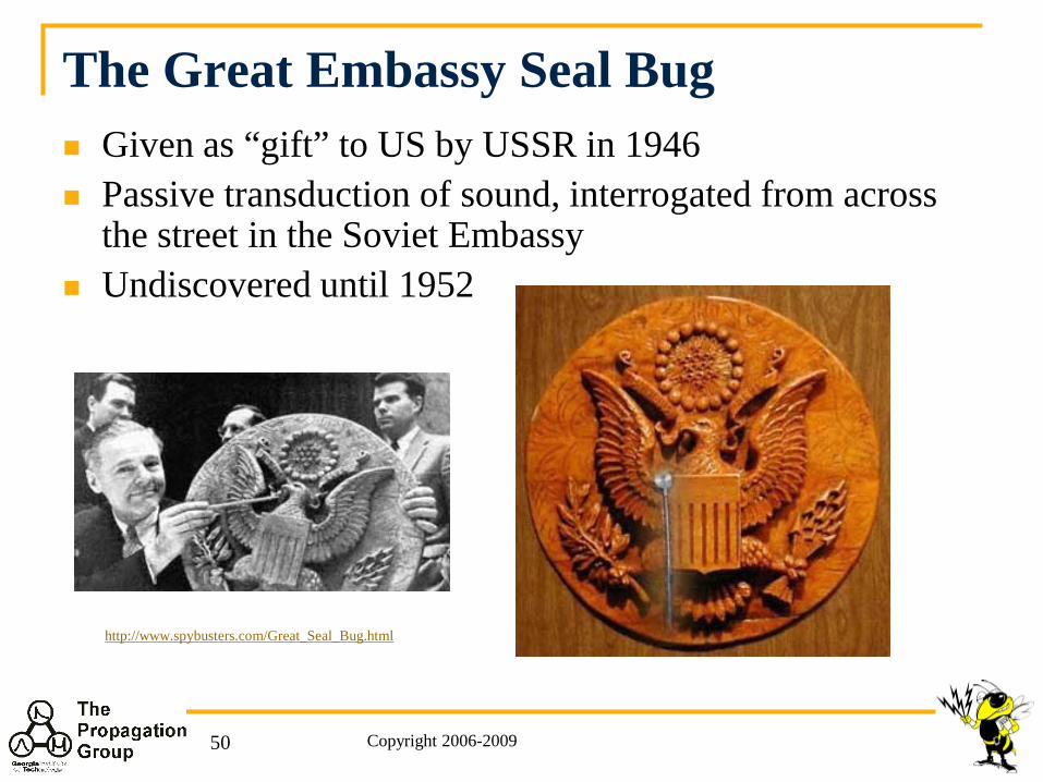
The Great Embassy Seal Bug Given as “gift” to US by USSR in 1946 Passive transduction of sound, interrogated from across
the street in the Soviet Embassy Undiscovered until 1952
Copyright 2006-200950
http://www.spybusters.com/Great_Seal_Bug.html
Copyright 2006-200951
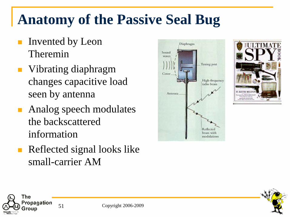
Anatomy of the Passive Seal Bug Invented by Leon
Theremin Vibrating diaphragm
changes capacitive load seen by antenna
Analog speech modulates the backscattered information
Reflected signal looks like small-carrier AM
THE FUNDAMENTALS OF BACKSCATTER RFID PROPAGATION
Copyright 2009 52
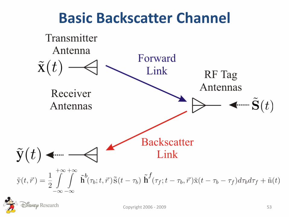
Basic Backscatter Channel
Copyright 2006 - 2009 53
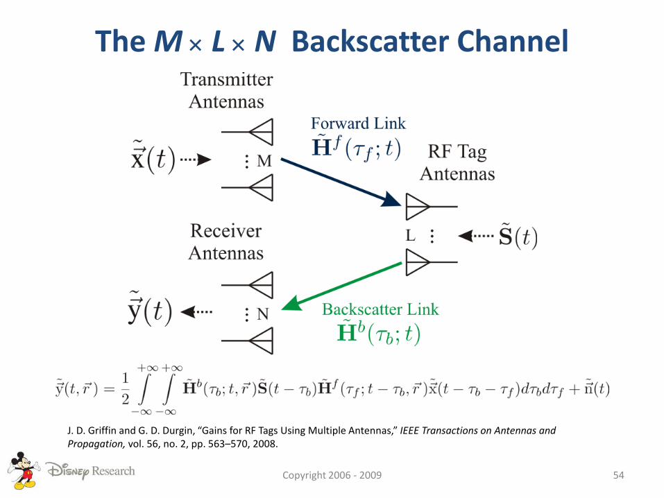
The M × L × N Backscatter Channel
Copyright 2006 - 2009 54
J. D. Griffin and G. D. Durgin, “Gains for RF Tags Using Multiple Antennas,” IEEE Transactions on Antennas and Propagation, vol. 56, no. 2, pp. 563–570, 2008.
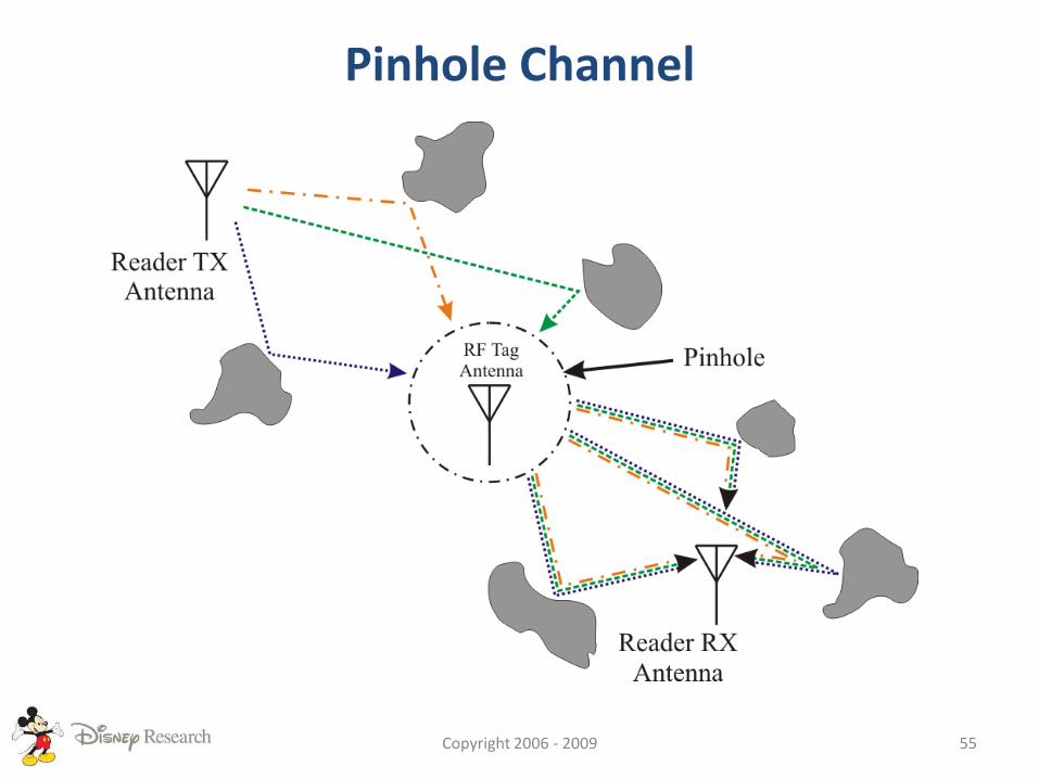
Pinhole Channel
Copyright 2006 - 2009 55
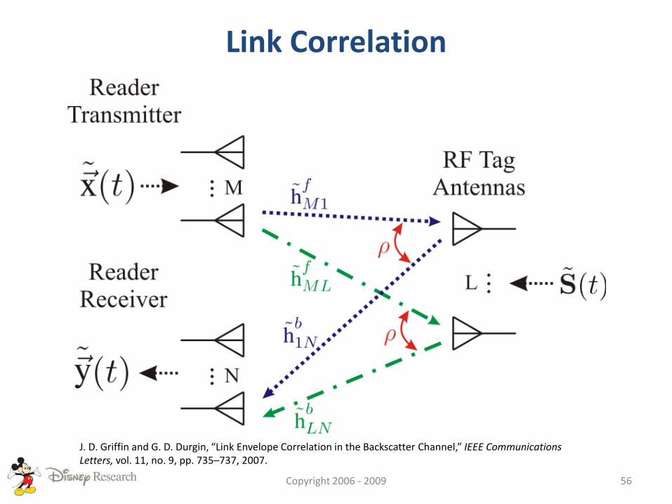
Link Correlation
Copyright 2006 - 2009 56
J. D. Griffin and G. D. Durgin, “Link Envelope Correlation in the Backscatter Channel,” IEEE Communications Letters, vol. 11, no. 9, pp. 735–737, 2007.
Channel Summary• The M x L x N Backscatter – a general channel in
which a backscatter radio system with Mtransmitter, L RF tag, and N receiver antennas operates.
• It is a pinhole channel which implies two sub-links– Forward Link
– Backscatter Link
• Link correlation describes the relationship between the fading in the forward and backscatter links.
Copyright 2009 57

RADIO LINK BUDGETS FOR BACKSCATTER RFID
Copyright 2009 58
Link Budgets• Fundamentally, power is the critical factor that
limits wireless system performance.• Link budgets are used by wireless engineers to
account for all of the power gains and losses in their system.
• Conventional Radio – one link budget• Backscatter Radio – two link budgets are
needed:– The power-up link budget– The backscatter link budget
Copyright 2009 59

Power-Up Link Budget
Copyright 2006 - 2009 60
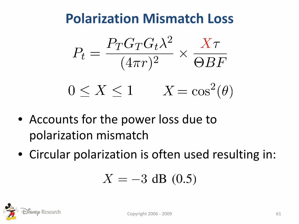
Polarization Mismatch Loss
• Accounts for the power loss due to polarization mismatch
• Circular polarization is often used resulting in:
Copyright 2006 - 2009 61
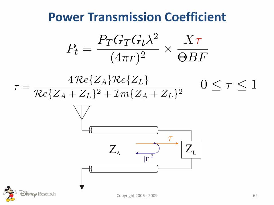
Power Transmission Coefficient
Copyright 2006 - 2009 62
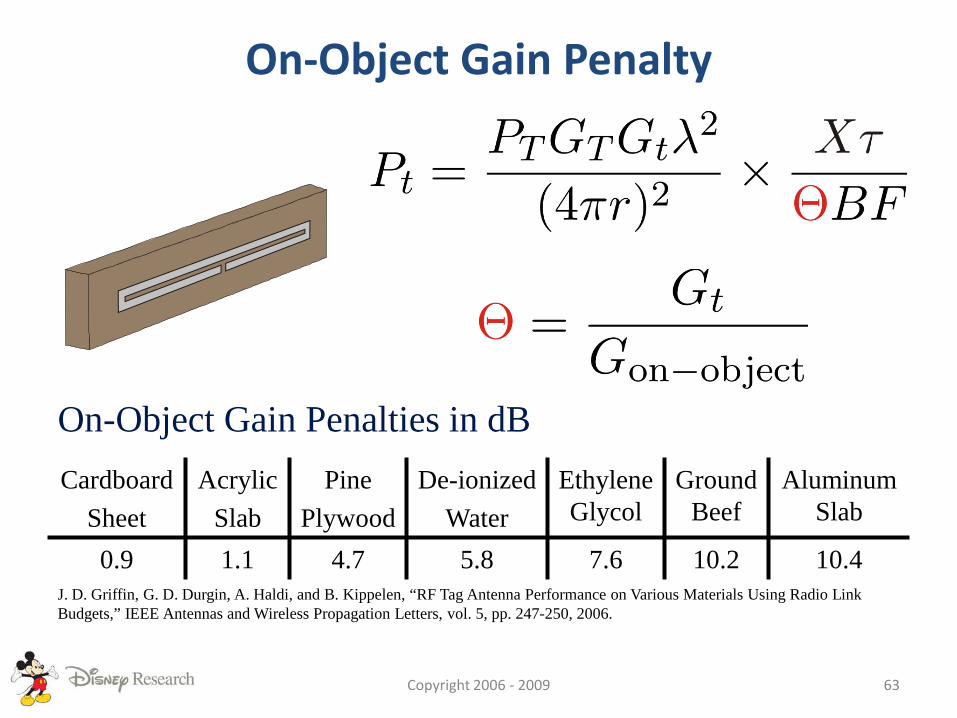
On-Object Gain Penalty
On-Object Gain Penalties in dBCardboard
SheetAcrylic
SlabPine
PlywoodDe-ionized
WaterEthylene Glycol
Ground Beef
Aluminum Slab
0.9 1.1 4.7 5.8 7.6 10.2 10.4J. D. Griffin, G. D. Durgin, A. Haldi, and B. Kippelen, “RF Tag Antenna Performance on Various Materials Using Radio Link Budgets,” IEEE Antennas and Wireless Propagation Letters, vol. 5, pp. 247-250, 2006.
Copyright 2006 - 2009 63
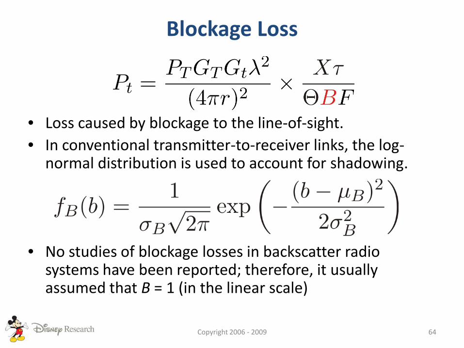
Blockage Loss
• Loss caused by blockage to the line-of-sight.• In conventional transmitter-to-receiver links, the log-
normal distribution is used to account for shadowing.
• No studies of blockage losses in backscatter radio systems have been reported; therefore, it usually assumed that B = 1 (in the linear scale)
Copyright 2006 - 2009 64
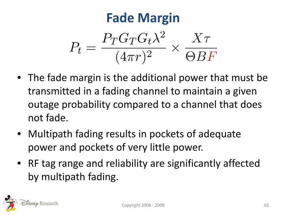
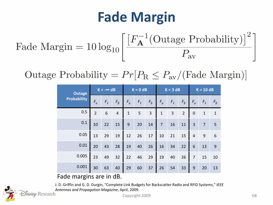
Fade Margin
• The fade margin is the additional power that must be transmitted in a fading channel to maintain a given outage probability compared to a channel that does not fade.
• Multipath fading results in pockets of adequate power and pockets of very little power.
• RF tag range and reliability are significantly affected by multipath fading.
Copyright 2006 - 2009 65
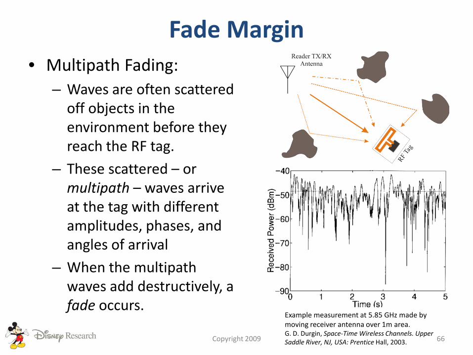
Fade Margin• Multipath Fading:
– Waves are often scattered off objects in the environment before they reach the RF tag.
– These scattered – or multipath – waves arrive at the tag with different amplitudes, phases, and angles of arrival
– When the multipath waves add destructively, a fade occurs.
Copyright 2009 66
Example measurement at 5.85 GHz made by moving receiver antenna over 1m area.G. D. Durgin, Space-Time Wireless Channels. Upper Saddle River, NJ, USA: Prentice Hall, 2003.

Fade Margin• Multipath fading is usually characterized using
a probability distribution function– Rayleigh distribution – if the line-of-sight is
blocked
– Rician – if the line-of-sight is unobstructed
Copyright 2009 67
Fade Margin
Copyright 2009 68
Outage Probability
K = -∞ dB K = 0 dB K = 3 dB K = 10 dB
Fp F2 Fβ Fp F2 Fβ Fp F2 Fβ Fp F2 Fβ
0.5 2 6 4 1 5 3 1 3 2 0 1 1
0.1 10 22 15 9 20 14 7 16 11 3 7 5
0.05 13 29 19 12 26 17 10 21 15 4 9 6
0.01 20 43 28 19 40 26 16 34 22 6 13 9
0.005 23 49 32 22 46 29 19 40 26 7 15 10
0.001 30 63 40 29 60 37 26 54 33 9 20 13
Fade margins are in dB.J. D. Griffin and G. D. Durgin, “Complete Link Budgets for Backscatter Radio and RFID Systems,” IEEE Antennas and Propagation Magazine, April, 2009.
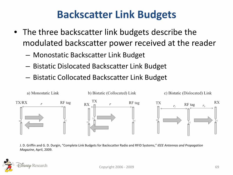
Backscatter Link Budgets
• The three backscatter link budgets describe the modulated backscatter power received at the reader– Monostatic Backscatter Link Budget
– Bistatic Dislocated Backscatter Link Budget
– Bistatic Collocated Backscatter Link Budget
Copyright 2006 - 2009 69
J. D. Griffin and G. D. Durgin, “Complete Link Budgets for Backscatter Radio and RFID Systems,” IEEE Antennas and Propagation Magazine, April, 2009.
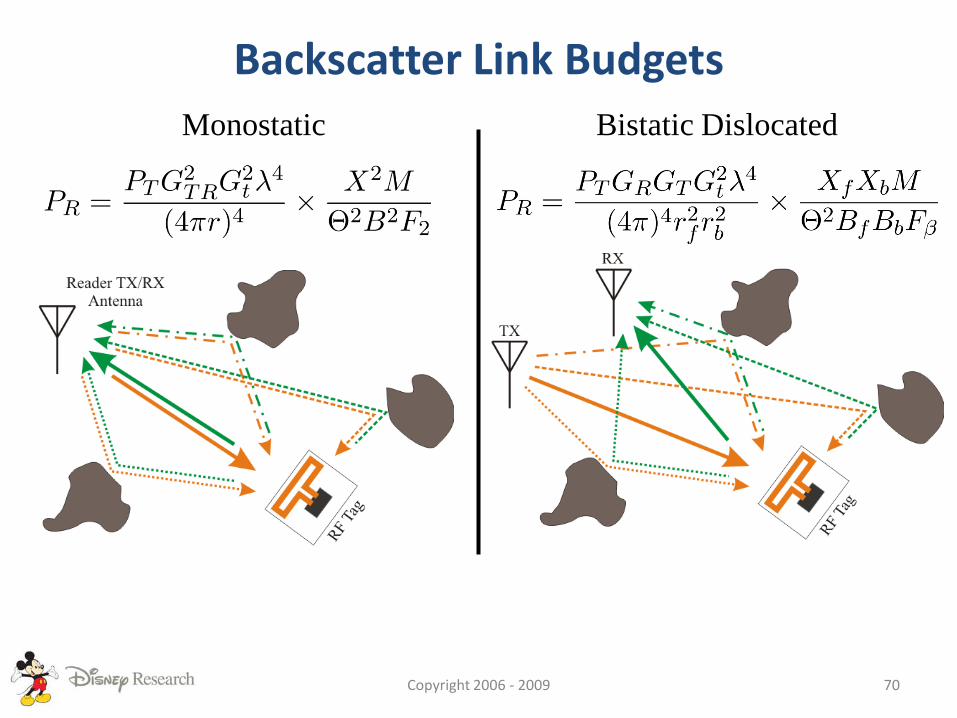
Backscatter Link Budgets
Copyright 2006 - 2009 70
Monostatic Bistatic Dislocated
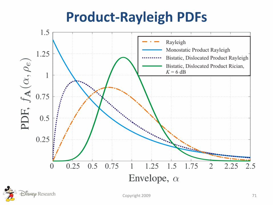
Product-Rayleigh PDFs
Copyright 2009 71

Backscatter Fade Margins
Copyright 2009 72
Outage Probability
K = -∞ dB K = 0 dB K = 3 dB K = 10 dB
Fp F2 Fβ Fp F2 Fβ Fp F2 Fβ Fp F2 Fβ
0.52 6 4 1 5 3 1 3 2 0 1 1
0.110 22 15 9 20 14 7 16 11 3 7 5
0.0513 29 19 12 26 17 10 21 15 4 9 6
0.0120 43 28 19 40 26 16 34 22 6 13 9
0.00523 49 32 22 46 29 19 40 26 7 15 10
0.00130 63 40 29 60 37 26 54 33 9 20 13
Fade margins are in dB.
J. D. Griffin and G. D. Durgin, “Complete Link Budgets for Backscatter Radio and RFID Systems,” IEEE Antennas and Propagation Magazine, April, 2009.
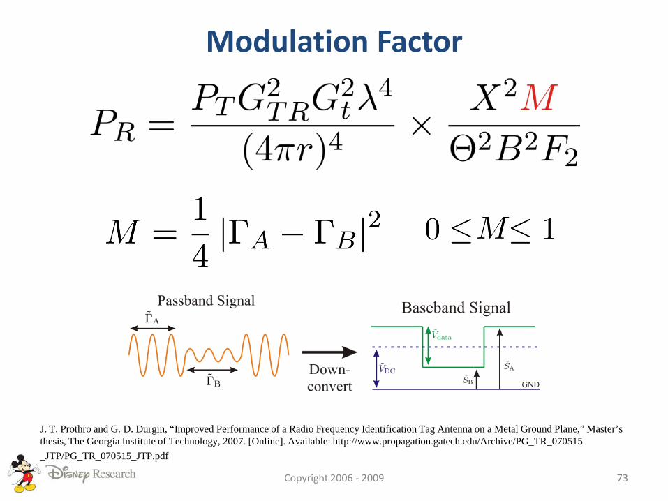
Modulation Factor
Copyright 2006 - 2009 73
J. T. Prothro and G. D. Durgin, “Improved Performance of a Radio Frequency Identification Tag Antenna on a Metal Ground Plane,” Master’s thesis, The Georgia Institute of Technology, 2007. [Online]. Available: http://www.propagation.gatech.edu/Archive/PG_TR_070515_JTP/PG_TR_070515_JTP.pdf

Differential Radar Cross Section
• The radar cross section (RCS) of an RF tag is defined as:
• As the tag switches between states A and B, the differential RCS is
Copyright 200974
P. V. Nikitin, K. V. S. Rao, and R. D. Martinez, “Differential RCS of RFID Tag,” Electronics Letters, vol. 43, no. 8, pp. 431–432, 2007.
TYPICAL UHF RFID PERFORMANCE SHOWN THROUGH EXAMPLE
Copyright 2009 75
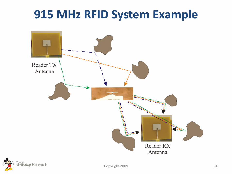
915 MHz RFID System Example
Copyright 2009 76
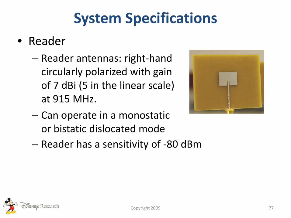
System Specifications• Reader
– Reader antennas: right-hand circularly polarized with gain of 7 dBi (5 in the linear scale) at 915 MHz.
– Can operate in a monostatic or bistatic dislocated mode
Copyright 2009 77
– Reader has a sensitivity of -80 dBm
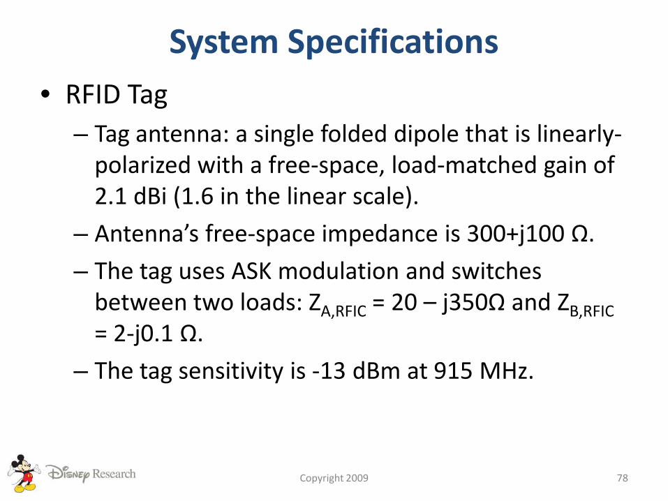
System Specifications• RFID Tag
– Tag antenna: a single folded dipole that is linearly-polarized with a free-space, load-matched gain of 2.1 dBi (1.6 in the linear scale).
– Antenna’s free-space impedance is 300+j100 Ω.
– The tag uses ASK modulation and switches between two loads: ZA,RFIC = 20 – j350Ω and ZB,RFIC= 2-j0.1 Ω.
– The tag sensitivity is -13 dBm at 915 MHz.
Copyright 2009 78
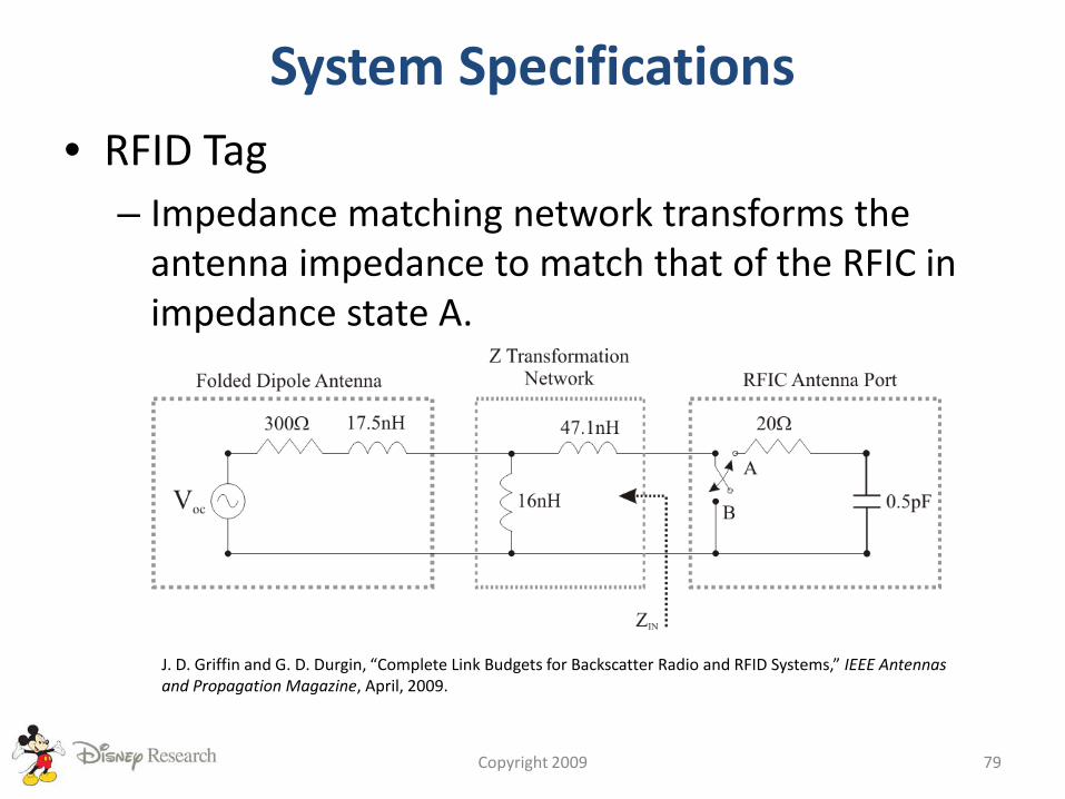
System Specifications• RFID Tag
– Impedance matching network transforms the antenna impedance to match that of the RFIC in impedance state A.
Copyright 2009 79
J. D. Griffin and G. D. Durgin, “Complete Link Budgets for Backscatter Radio and RFID Systems,” IEEE Antennas and Propagation Magazine, April, 2009.
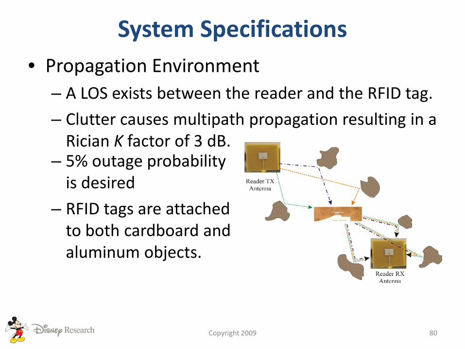
System Specifications• Propagation Environment
– A LOS exists between the reader and the RFID tag.
– Clutter causes multipath propagation resulting in a Rician K factor of 3 dB.
Copyright 2009 80
– 5% outage probability is desired
– RFID tags are attached to both cardboard and aluminum objects.
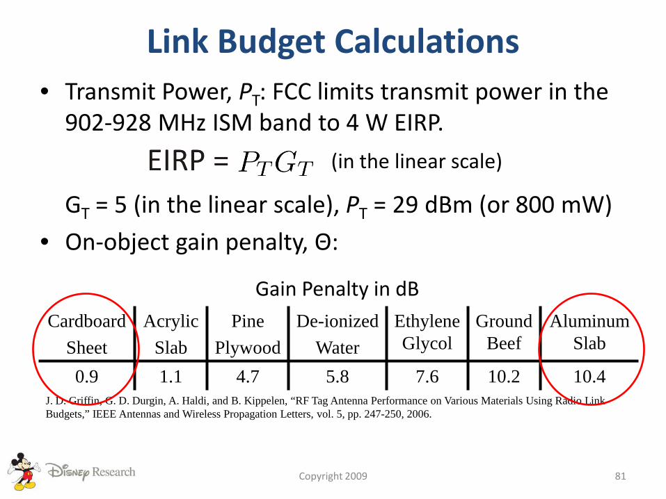
Link Budget Calculations• Transmit Power, PT: FCC limits transmit power in the
902-928 MHz ISM band to 4 W EIRP.
GT = 5 (in the linear scale), PT = 29 dBm (or 800 mW)
• On-object gain penalty, Θ:
Copyright 2009 81
(in the linear scale)
CardboardSheet
AcrylicSlab
PinePlywood
De-ionizedWater
Ethylene Glycol
Ground Beef
Aluminum Slab
0.9 1.1 4.7 5.8 7.6 10.2 10.4J. D. Griffin, G. D. Durgin, A. Haldi, and B. Kippelen, “RF Tag Antenna Performance on Various Materials Using Radio Link Budgets,” IEEE Antennas and Wireless Propagation Letters, vol. 5, pp. 247-250, 2006.
Gain Penalty in dB
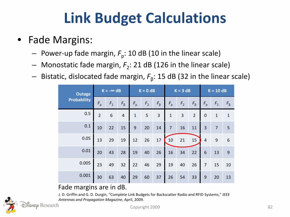
Link Budget Calculations• Fade Margins:
– Power-up fade margin, Fp: 10 dB (10 in the linear scale)
– Monostatic fade margin, F2: 21 dB (126 in the linear scale)
– Bistatic, dislocated fade margin, Fβ: 15 dB (32 in the linear scale)
Copyright 2009 82
Outage Probability
K = -∞ dB K = 0 dB K = 3 dB K = 10 dB
Fp F2 Fβ Fp F2 Fβ Fp F2 Fβ Fp F2 Fβ
0.5 2 6 4 1 5 3 1 3 2 0 1 1
0.1 10 22 15 9 20 14 7 16 11 3 7 5
0.05 13 29 19 12 26 17 10 21 15 4 9 6
0.01 20 43 28 19 40 26 16 34 22 6 13 9
0.005 23 49 32 22 46 29 19 40 26 7 15 10
0.001 30 63 40 29 60 37 26 54 33 9 20 13
Fade margins are in dB.J. D. Griffin and G. D. Durgin, “Complete Link Budgets for Backscatter Radio and RFID Systems,” IEEE Antennas and Propagation Magazine, April, 2009.
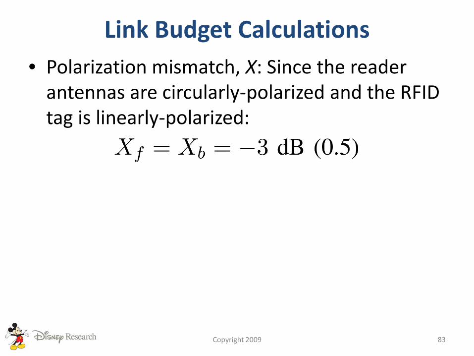
Link Budget Calculations• Polarization mismatch, X: Since the reader
antennas are circularly-polarized and the RFID tag is linearly-polarized:
Copyright 2009 83
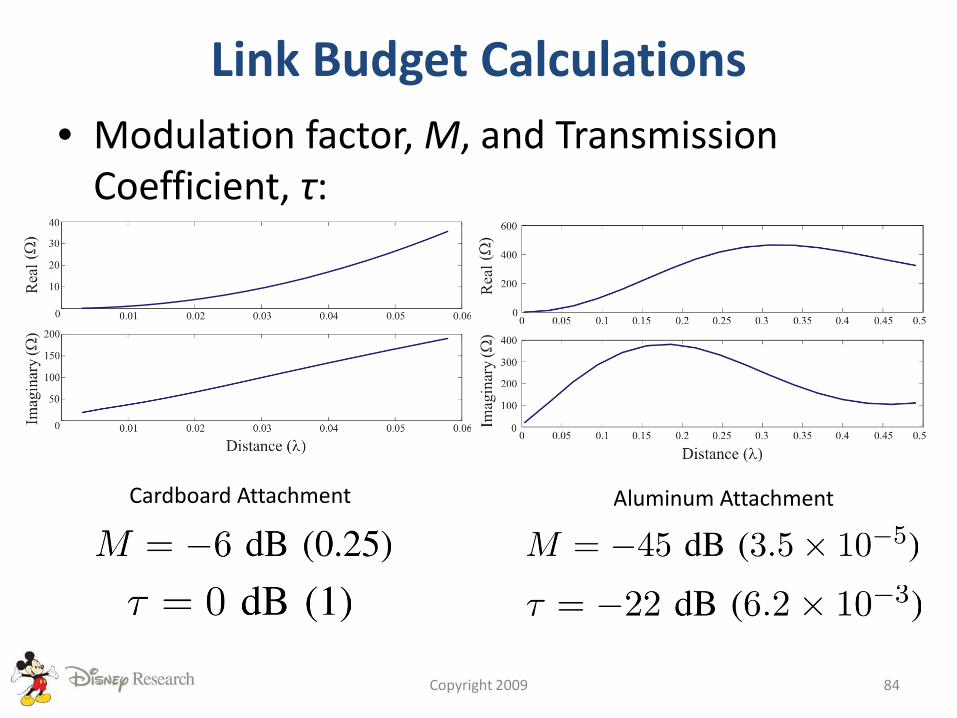
Link Budget Calculations• Modulation factor, M, and Transmission
Coefficient, τ:
Copyright 2009 84
Cardboard Attachment Aluminum Attachment
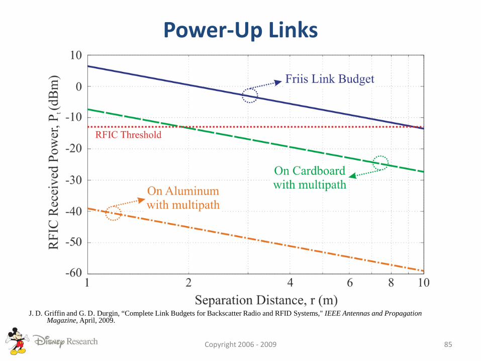
Power-Up Links
Copyright 2006 - 2009 85
J. D. Griffin and G. D. Durgin, “Complete Link Budgets for Backscatter Radio and RFID Systems," IEEE Antennas and Propagation Magazine, April, 2009.
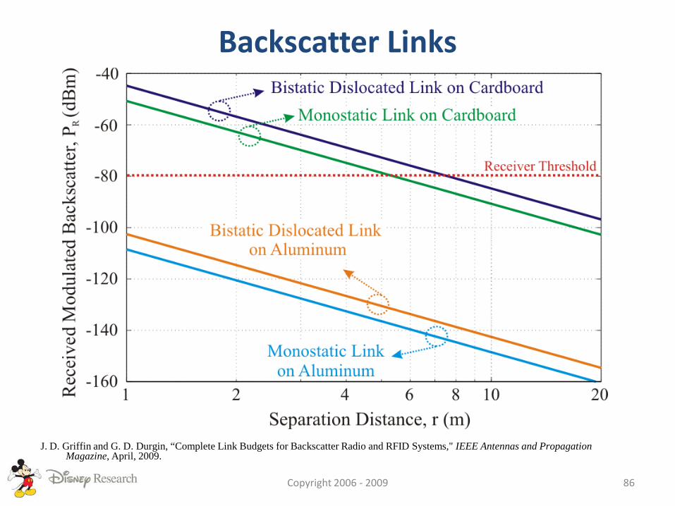
Backscatter Links
Copyright 2006 - 2009 86
J. D. Griffin and G. D. Durgin, “Complete Link Budgets for Backscatter Radio and RFID Systems," IEEE Antennas and Propagation Magazine, April, 2009.
Conclusion• RF tags are usually limited by the power-up
link, not by the backscatter link.
• Material attachment can have a significant effect on RF tag performance
• Link correlation reduces RF tag performance– Monostatic configuration
– Bistatic configuration
Copyright 2009 87
Further ReadingGeneral RFIDD. M. Dobkin, The RF in RFID: Passive UHF RFID in Practice. Burlington, MA: Newnes,
2008.K. Finkenzeller, RFID Handbook: Fundamentals and Applications in Contactless Smart
Cards and Identification, 2nd ed. New York: John Wiley and Son LTD, 2003.
General Antenna and PropagationW. L. Stutzman and G. A. Thiele, Antenna Theory and Design, 2nd ed. Hoboken, NJ:
John Wiley and Sons, 1998.G. D. Durgin, Space-Time Wireless Channels. Upper Saddle River, NJ, USA: Prentice Hall,
2003.
Introduction to RFIDL. Reindl, G. Scholl, T. Ostertag, C.C.W. Ruppel W. –E. Bulst, and F. Seifert, “SAW Devices
as Wireless Passive Sensors,” Proceedings of the 1996 IEEE Ultrasonics Symposium, vol. 1, San Antonio, TX, November, 1996, pp. 363-637.
K. V. S. Rao, P. V. Nikitin, and S. F. Lam, “Antenna Design for UHF RFID Tags: A Review and a Practical Application,” IEEE Transactions on Antennas and Propagation, vol. 53, no. 12, pp. 3870–3876, 2005.
P. Nikitin, K. V. S. Rao, and S. Lazar, “An Overview of Near Field UHF RFID,” in IEEE International Conference on RFID, Grapevine, TX, 2007, pp. 167–174.
Copyright 2009 88
Further ReadingRFID HistoryH. Stockman, “Communication by Means of Reflected Power,” Proceedings of the I.R.E,
vol. 36, no. 10, pp. 1196–1204, 1948.J. Landt, “The History of RFID,” IEEE Potentials, vol. 24, no. 4, pp. 8–11, 2005.
Backscatter RFID PropagationJ. D. Griffin and G. D. Durgin, “Gains for RF Tags Using Multiple Antennas,” IEEE
Transactions on Antennas and Propagation, vol. 56, no. 2, pp. 563–570, 2008.P. Nikitin and K. V. S. Rao, “Performance Limitations of Passive UHF RFID Systems,” in
Proceedings of IEEE Antenna and Propagation Society International Symposium, Albuquerque, New Mexico, 2006, pp. 1011–1014.
J. D. Griffin and G. D. Durgin, “Link Envelope Correlation in the Backscatter Channel,” IEEE Communications Letters, vol. 11, no. 9, pp. 735–737, 2007.
P. Nikitin and K. V. S. Rao, “Antennas and Propagation in UHF RFID Systems,” in IEEE International Conference on RFID, Las Vegas, TX, 2008, pp. 277–288.
M. Ingram, M. Demirkol, and D. Kim, “Transmit Diversity and Spatial Multiplexing for RF Links Using Modulated Backscatter,” in Proceedings of the International Symposium on Signals, Systems, and Electronics, Tokyo, Japan, July 2001.
Copyright 2009 89

Further ReadingS. R. Banerjee, R. Jesme, and R. A. Sainati, “Performance Analysis of Short Range UHF
Propagation as Applicable to Passive RFID,” in 2007 IEEE International Conference on RFID, Gaylord Texan Resort, Grapevine, TX, USA, March 2007, pp. 30–36.
S. R. Banerjee, R. Jesme, and R. A. Sainati, “Investigation of Spatial and Frequency Diversity for Long Range UHF RFID,” in IEEE Antennas and Propagation Society International Symposium, San Diego, CA, USA, July 2008, pp. 1–4.
Radio Link Budgets for Backscatter RFIDJ. D. Griffin and G. D. Durgin, “Complete Link Budgets for Backscatter Radio and RFID
Systems,” IEEE Antennas and Propagation Magazine, April, 2009.J. D. Griffin, G. D. Durgin, A. Haldi, and B. Kippelen, “RF Tag Antenna Performance on
Various Materials Using Radio Link Budgets,” IEEE Antennas and Wireless Propagation Letters, vol. 5, pp. 247–250, 2006.
D. M. Dobkin and S. M. Weigand, “Environmental Effects on RFID Tag Antennas,” in IEEE MTT-S International Microwave Symposium Digest, 2005, pp. 135–138.
J. T. Prothro and G. D. Durgin, “Improved Performance of a Radio Frequency Identification Tag Antenna on a Metal Ground Plane,” Master’s thesis, The Georgia Institute of Technology, 2007. [Online]. Available: http://www.propagation.gatech.edu/Archive/PG_TR_070515_JTP/PG_TR_070515_JTP.pdf
Copyright 2009 90
Further ReadingD. Kim, M. A. Ingram, and W. W. Smith, Jr., “Measurements of Small-scale Fading and
Path Loss for Long Range RF Tags,” IEEE Transactions on Antennas and Propagation, vol. 51, no. 8, pp. 1740–1749, 2003.
P. V. Nikitin, K. V. S. Rao, and R. D. Martinez, “Differential RCS of RFID Tag,” Electronics Letters, vol. 43, no. 8, pp. 431–432, 2007.
Copyright 2009 91